o.k. - dungs® combustion controls spring-loaded ratio regulator / zero governor with adjustable...
TRANSCRIPT
1 … 9
MC
• Ka
rl D
ungs
, Inc
. • F
RG R
atio
Reg
ulat
or /
Zero
Gov
erno
r • E
ditio
n 20
17.0
7 • P
/N 2
6140
1
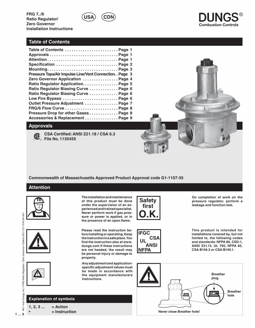
CSA Certified: ANSI Z21.18 / CSA 6.3File No. 1135455
Commonwealth of Massachusetts Approved Product Approval code G1-1107-35
FRG 7../6 Ratio Regulator/ Zero GovernorInstallation Instructions
Table of Contents
USA CDN
Table of Contents . . . . . . . . . . . . . . . . . . . . . . . . Page 1Approvals . . . . . . . . . . . . . . . . . . . . . . . . . . . . . . . Page 1Attention . . . . . . . . . . . . . . . . . . . . . . . . . . . . . . . . Page 1Specification . . . . . . . . . . . . . . . . . . . . . . . . . . . . Page 2Mounting. . . . . . . . . . . . . . . . . . . . . . . . . . . . . . . . Page 3Pressure Taps/Air Impulse Line/Vent Connection. . Page 3Zero Governor Application . . . . . . . . . . . . . . . . Page 4Ratio Regulator Application. . . . . . . . . . . . . . . . Page 5Ratio Regulator Biasing Curve . . . . . . . . . . . . . Page 6Ratio Regulator Biasing Curve . . . . . . . . . . . . . Page 6Low Fire Bypass . . . . . . . . . . . . . . . . . . . . . . . . . Page 6Outlet Pressure Adjustment . . . . . . . . . . . . . . . Page 7FRG/6 Flow Curve . . . . . . . . . . . . . . . . . . . . . . . . Page 8Pressure Drop for other Gases . . . . . . . . . . . . . Page 8Accessories & Replacement . . . . . . . . . . . . . . . Page 9
Approvals
1, 2, 3 ... = Action• = Instruction
Explanation of symbols
Attention
On completion of work on the pressure regulator, perform a leakage and function test.
Please read the instruction be-fore installing or operating. Keep the instruction in a safe place. You find the instruction also at www.dungs.com If these instructions are not heeded, the result may be personal injury or damage to property.Any adjustment and application-specific adjustment values must be made in accordance with the equipment manufacturers instructions.
IFGCCSAUL
ANSINFPA
This product is intended for installations covered by, but not limited to, the following codes and standards: NFPA 86, CSD-1, ANSI Z21.13, UL 795, NFPA 85, CSA B149.3 or CSA B149.1.
Breather plug
Never close Breather hole!
Breather hole
Safetyfirst
O.K.
The installation and maintenance of this product must be done under the supervision of an ex-perienced and trained specialist. Never perform work if gas pres-sure or power is applied, or in the presence of an open flame.

3 … 92 … 9
MC
• Ka
rl D
ungs
, Inc
. • F
RG R
atio
Reg
ulat
or /
Zero
Gov
erno
r • E
ditio
n 20
17.0
7 • P
/N 2
6140
1
Specification
Max. Operating Pressure (MOP)7 PSI (500 mbar) 5 PSI (350 mbar) applies to the CSA Certification.
Ambient / Fluid TemperatureFRG 7../6 series: • +5 °F to +160 °F for up to 7 PSI for
regulating behavior (+/- 10 % of setpoint)• CSA Certified for -40°F to +160 °F
for up to 5 PSI: Diaphragms are suitable for the low temperature, but there may be out of range regulating behavior.
GasesDry, natural gas, propane, butane; other noncorrosive gases. Suitable for up to 0.1 % by volume, dry H2S. A “dry” gas has a dew point lower than +15 °F and its relative humidity is less than 60 %.Materials in contact with GasHousing: AluminumSeals & Diaphragm: NBR-based rubber
°F
0-40
+160
FRG/6 Spring-loaded ratio regulator / zero governor with adjustable setpoint spring and defined counterspring. Internal sensing of output pressure; air impulse line connection is standard.
Optimal Inlet Pressure RangeRatio Regulator: 3 to 82 in. W.C. (7 to 200 mbar)Zero Governor: 3 to 20 in. W.C. (7 to 50 mbar) with 10:1 turndown.Zero Governor: 3 to 82 in. W.C. (7 to 200 mbar) with 3:1 turndown.Output Pressure RangeRatio Regulator: -4 to 60 in. W.C. (-10 to 150 mbar)Zero Governor: -2 to 1 in. W.C. (-5 to 3 mbar)
Gas
Body Size Order No. SizeFRG 705/6 226458 1/2“ NPTFRG 707/6 226459 3/4“ NPTFRG 710/6 226460 1“ NPTFRG 712/6 226461 1 1/4“ NPTFRG 715/6 226462 1 1/2“ NPTFRG 720/6 226463 2“ NPTFRG 725/6 226464 2 1/2“ NPTFRG 730/6 226465 3“ NPT
[PSI]
Vent Limiting Device and Vent Line ConnectionThe FRG/6 has an internal, factory installed vent limiter, which limits the escape of gas to less than 0.5 CFH @ 5 PSI in case atmospheric diaphragm ruptures. Vent limiting device also complies with EN 88 & ISO 2355-1. Venting required unless otherwise accepted by the authority having jurisdiction.

3 … 92 … 9
MC
• Ka
rl D
ungs
, Inc
. • F
RG R
atio
Reg
ulat
or /
Zero
Gov
erno
r • E
ditio
n 20
17.0
7 • P
/N 2
6140
1Recommended Mounting ProcedureRegulator dome from vertically upright to lying horizontally
Mounting
If the flow is not in the same direction of the arrows, the regulator will not operate properly.
Recommended Preparation • The main gas supply must be shut off before starting the
installation.• Read these installation instructions carefully.• Carefully examine the FRG/6 for shipping damage.• Remove the two red plastic covers from the FRG/6 body.• Remove all dirt and debris before installing the FRG/6. Fail-
ure to remove dirt/debris could result in damage or improper performance.
Recommended Procedure to Mount the FRG/6• Install the FRG/6 with the gas flow matching the direction
indicated by the arrows on the casting.• Mount the FRG/6 with the regulator vertical or horizontal.• Use new, properly reamed and threaded pipe free of chips.• Apply good quality pipe sealant, putting a moderate amount
on the male threads only. If using LP gas, use pipe sealant rated for use with LP gas.
• Do not thread pipe too far. FRG/6 distortion and/or malfunc-tion may result from excess pipe in the valve body.
Apply counter pressure with a parallel jaw wrench only to the flats of the FRG/6 when installing pipe.
• Do not overtighten the pipe. Follow the maximum torque values listed.
• After installation is complete, perform a leak test.
• As a proportionator, this is an air impulse line connection. As a zero govenor, this is a breathing plug or a vent connection.
NOTE: All FRGs have a factory installed vent limiting device under the regulator housing. Connection is G 1/4 for FRG 705/6 to FRG 710/6 and G 1/2 for FRG 712/6 to FRG 730/6. G thread to NPT thread adapters are available. G 1/4 to 1/4”NPT adapter (Order No. 231944) and G 1/2 to 1/2 NPT adapter (Order No. 231945).
• Pressure tap connection in inlet section, both sides 1/4” NPT.• Pressure tap connection in outlet section, both sides 1/4“ NPT.
1
23
NPT pipe
1/2” 3/4” 1” 11/4” 11/2” 2” 21/2” 3”
Tmax[Ib-in]
443 752 1106 1770 1991 2213 2876 3540If the flow is not in the same direction as the arrows, the FRG/6 will not operate properly.
Pressure Taps/Air Impulse Line/Vent ConnectionTest PortWhen low fire bypass is used, only test ports on one side can be used.
2 3
Low fire bypass option for FRG 705/6 - 720/6Order No. 225256

5 … 94 … 9
MC
• Ka
rl D
ungs
, Inc
. • F
RG R
atio
Reg
ulat
or /
Zero
Gov
erno
r • E
ditio
n 20
17.0
7 • P
/N 2
6140
1
Application - Zero governor For use with gas engines or premix burners, the FRG controls flow by reducing upstream gas pressure to zero or adjustable to slightly above or below atmospheric pressure.
The outlet pressure is adjustable with the setpoint spring.
For Vmax see flow diagram on page 6.°
0.95 (gas) : 1 (air)
Outlet pressurep2 [”W.C.]
Vmax. at high fire°V [CFH]°
The above illustration shows adjustability (fuel biasing) of the FRG/6 when used as a zero governor. Refer to page 6 for siz-ing FRG/6 at maximum flow rate.
Zero governor outlet pressure
Gas Equipment
Gas
FRG/6Mixer
Air Filter
Adjusting the FRG/6 1. For zero governor applications, the FRG should be ad-
justed at low fire only.2. If the FRG is not flowing enough gas at the maximum air
flow rate, the gas flow can be increased by any of the following:
a.) Increase the negative signal to the FRG. b.) Install a larger FRG.
Zero Governor Application
Do not mount the zero governor upside down.

5 … 94 … 9
MC
• Ka
rl D
ungs
, Inc
. • F
RG R
atio
Reg
ulat
or /
Zero
Gov
erno
r • E
ditio
n 20
17.0
7 • P
/N 2
6140
1Application - Ratio RegulatorThe FRG holds a constant gas/air ratio during turndown by varying gas flow to the burner in proportion to the combus-tion air flow. Adjustable for excess air or gas.
Setup ProcedureWhen setting up the FRG/6 and burner for proper ratio at all firing rates, follow the burner manufacturer’s instructions. The following procedure contains recom-mended guidelines only, and they do not supercede the burner manufacturer’s procedures for setting up and adjusting the FRG/6 to the burner.
Low Fire AdjustmentThe adjustable top loading spring on the FRG/6 is a low fire adjustment (see outlet pressure adjustment on page 2). If the tension on this spring is at a minumum and there is still too much gas flow at low fire, achieving a lower flow rate is possible by reducing the air impluse line pressure to 2”WC or less. If the air impluse line pressure cannot be reduced, a lower flow rate can be acheived by installing a smaller FRG/6.In order to achieve a low fire flow rate in the range of 20-100 CFH, a field mount-able low fire bypass restrictor (225256) is recommended. See “Flow curve for Low fire bypass” on page 5 for more details. When using the low fire bypass restrictor, it is recommended that the top loading
spring be adjusted so that the FRG/6 regulating disc opens just as the impulse line increases during the ramp-up cycle. If the loading spring tension is too small, there will be a delayed increase of fuel flow as the air flow increase until the loading line pressure is greater than the counterspring force, and the result can be a lean burner over a small range of inputs near low fire. CAUTION: Multiple burners and low fire adjustment. It is not recommended to use a control scheme or gas piping scheme that does not equally distribute the gas pressure to each burner at low fire. Examples of such shemes could include using one FRG/6 to control the gas flow to more than one burner, or using one air control valve to feed two FRG’s and a second air control valve to feed three FRG’s. Such a control scheme will likely not allow for optimal low fire adjustment at each burner. CAUTION: Purge and low fire start.A burner (or set of burners) that light immediately after a purge that is longer the 60 seconds can cause a 5-20 sec-ond (depending on the purge pressure) slightly fuel rich condition at the low fire start. If such a case occurs, it is recom-mended that the loading line pressure during the purge be vented, or that lighoff be delayed just lone enough to eliminate the slightly fuel rich condition at the low fire start.
High Fire AdjustmentAdditional adjustments might be needed at high fire, depending on the type of burner, piping arrangement, flow, air impluse line pressure, and the model of FRG/6 installed on the burner. NOTE: The burner might have an integrated gas limiting valve or an air balancing valve (see illustration below). If these are not provided on the burner, installing them might be needed in order to achieve the correct ratio at high fire.In cases where the high fire rate is fuel rich, partially close the gas limiting valve located downstream of the FRG/6 in order to achieve proper ratio. This ad-justment reduces the gas pressure in the burner without affecting the air pressure. Re-adjust the low fire ratio if needed. In cases where the high firing rate is fuel lean, first verify that the inlet gas pressure to the FRG/6 is and remains at least 2”WC higher than the air impluse line pressure at high fire. If there is suitable inlet gas pressure to the FRG/6, then more fuel to the burner can be accomplished by either installing a larger FRG/6 or by partially closing the air balancing valve located downstream of the control valve to achieve proper ratio; this adjustment reduces the air pressure in the burner and increases the impulse line pressure on the FRG/6. Re-adjust the low fire ratio if needed. Adjusting the FRG/6 See out pressure adjustment on page 2.
Butterfly Control Valve
Bias (Low Fire adjustment ONLY)
FRG/6Gas Limiting Valve(High Fire Adjustment)
Air Balancing Valve(High Fire Adjustment)
Burner
Two pipe diameters MIN. Five pipe diameters MIN.
Air impusle loading line
Ratio Regulator Application
The size of the air impulse line should match the FRG/6
air impulse line connection. It should be as short as possible with as few bends as possible
The low fire air impulse line pressure should be between
0.2 and 1.0 In. W.C.
Do not mount the FRG upsidedown.

7 … 96 … 9
MC
• Ka
rl D
ungs
, Inc
. • F
RG R
atio
Reg
ulat
or /
Zero
Gov
erno
r • E
ditio
n 20
17.0
7 • P
/N 2
6140
1
40
30
20
10
225256
0.95 (gas) : 1 (air)
Outlet pressurep2 [”W.C.]
Vmax. at high fire°V [CFH]°
40
30
20
10
225256
Mounting the Low Fire Bypass
1. Remove the pressure tap plate with a Torx™ driver size T20.
2. Line up the low fire bypass making sure that the O-ring is seated cor-rectly. Reinstall with the screws from the pressure tap mounting plate.
3. Perform a leak test after torquing the low fire bypass.
Adjusting the Low Fire Bypass
1. Remove the black cover2. With a slotted screwdriver turn the
adjustment screw clockwise for LESS gas and counter clockwise for MORE gas flow.
3. Secure cap with a wire seal.
Low fire bypass Flow adjustmentMounting of low fire bypass
The above illustration shows that the air impulse line can be adjusted to achieve excess air, excess gas, or on ratio at low fire. However, the air impulse line slightly exceeds the gas outlet pressure at high fire rate.
Flow Curve for Low fire bypass
Ratio Regulator Biasing Curve
Low Fire Bypass
Ratio Regulator Biasing Curve
Low fire bypass max. Torque 1.85 Lb-in.
The low fire bypass is factory set for maximum flow.
, Please note: only FRG 705/6 - 720/6

7 … 96 … 9
MC
• Ka
rl D
ungs
, Inc
. • F
RG R
atio
Reg
ulat
or /
Zero
Gov
erno
r • E
ditio
n 20
17.0
7 • P
/N 2
6140
1
Cover Top View
Adjusting the FRG/6 1. Remove the black cover.2. To increase outlet pressure turn the adjustment spindle
clockwise, to decrease the outlet pressure turn the adjust-ment spindle counterclockwise.
3. Always use an accurate pressure guage connected down stream from the requlator to measure the actual outlet pressure.
4. Reinstall the black cover.5. After adjusting the set point for normal operation check to
see that the gas pressure regulator operates as intended.6. Use holes in the black cover and the side of the regulator
to secure a lead seal to prevent unauthorized adjustment.
Outlet Pressure Adjustment
13
An internal adjustment limits (but does not pre-vent) the risk of a gas rich flame.

9 … 98 … 9
MC
• Ka
rl D
ungs
, Inc
. • F
RG R
atio
Reg
ulat
or /
Zero
Gov
erno
r • E
ditio
n 20
17.0
7 • P
/N 2
6140
1
Pressure Drop for other GasesTo determine the pressure drop when using a gas other than natural gas, use the flow formula below and f value located in the table below to determine the “corrected” flow rate in CFH through the valve for the other gas used. For example,
when using propane, divide the volume (CFH) of propane required for the application by the calculated value f (f = 0.66 for propane). Use this “corrected” flow rate and the flow curve on the next page to determine pressure drop for propane.
Density of Natural gas
Density of gas usedf =
Type of gas Density[kg/m3] s.g. f
Natural gas 0.81 0.65 1.00Butane 2.39 1.95 0.58Propane 1.86 1.50 0.66Air 1.24 1.00 0.80
Determining equivalent flow through valves using another gas
Vgas used = V Natural gas x f° °
FRG/6 Flow Curve
A minimum of 3 in. W.C. ∆p is required when sizing at maximum flow capacity for optimal control on high turndown applications (40:1). A 2 in. W.C. ∆p can be applied for sizing if a lower turndown (in the range of 10:1) is required.
Sizing the FRG/6 using a 1 in. W.C. ∆p or less is not recommended for most applications.

9 … 98 … 9
MC
• Ka
rl D
ungs
, Inc
. • F
RG R
atio
Reg
ulat
or /
Zero
Gov
erno
r • E
ditio
n 20
17.0
7 • P
/N 2
6140
1
Accessories & Replacement
FRG & FRNG Repair KitsDescription Diaphragm / Repair Kit Order No.FRG 705/6 Not availableFRG 707/6 Not availableFRG 710/6 Not availableFRG 712/6 & 715/6 Not availableFRG 720/6 229658FRG 725/6 229659FRG 730/6 229660
Karl Dungs GmbH & Co. KGP.O. Box 12 29D-73602 Schorndorf, GermanyPhone +49 (0)7181-804-0Fax +49 (0)7181-804-166e-mail [email protected] http://www.dungs.com
Karl Dungs, Inc.3890 Pheasant Ridge Drive NESuite 150Blaine, MN 55449, U.S.A.Phone 763 582-1700Fax 763 582-1799e-mail [email protected] http://www.dungs.com/usa/
We reserve the right to make modifications in the course of technical development.
Replacement Bias Spring / Loading SpringsDescription Order No.FRG 705/6 229817 (Bias Spring / Loading Spring)FRG 707/6 229833 (Bias Spring / Loading Spring)FRG 710/6 229842 (Bias Spring / Loading Spring)FRG 712/6 & 715/6 229851 (Bias Spring / Loading Spring)FRG 720/6 229874 (Bias Spring / Loading Spring)FRG 725/6 229883 (Bias Spring / Loading Spring)FRG 730/6 229883 (Bias Spring / Loading Spring)
Replacement PartsDescription Order No.Bypass Adapter (Restrictor) 225256 (Bypass Adapter for FRG up to 2“)Side plate (with two 1/4” NPT taps)
225132 (Includes gasket but not mounting screws)