okanogan project historic...
TRANSCRIPT

U.S. Department of the Interior Bureau of Reclamation October 2014 Pacific Northwest Region
Okanogan Project Historic Overview
By: Kelsey Doncaster Columbia-Cascades Area Office Historian
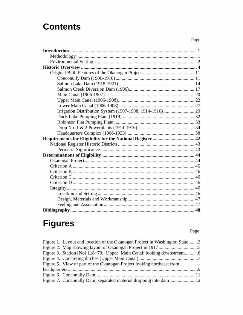
Contents
Page Introduction ........................................................................................................... 1
Methodology ..................................................................................................... 1 Environmental Setting ...................................................................................... 2
Historic Overview ................................................................................................. 4 Original Built Features of the Okanogan Project ............................................ 11
Conconully Dam (1906-1910) .................................................................. 11 Salmon Lake Dam (1918-1921)................................................................ 14 Salmon Creek Diversion Dam (1906)....................................................... 17 Main Canal (1906-1907) ........................................................................... 20 Upper Main Canal (1906-1908) ................................................................ 22 Lower Main Canal (1906-1908) ............................................................... 27 Irrigation Distribution System (1907-1908, 1914-1916) .......................... 29 Duck Lake Pumping Plant (1919) ............................................................. 32 Robinson Flat Pumping Plant ................................................................... 33 Drop No. 1 & 2 Powerplants (1914-1916)................................................ 34 Headquarters Complex (1906-1923)......................................................... 38
Requirements for Eligibility for the National Register ................................... 42 National Register Historic Districts ................................................................ 43
Period of Significance ............................................................................... 43 Determinations of Eligibility .............................................................................. 44
Okanogan Project ............................................................................................ 44 Criterion A ...................................................................................................... 45 Criterion B ...................................................................................................... 46 Criterion C ...................................................................................................... 46 Criterion D ...................................................................................................... 46 Integrity ........................................................................................................... 46
Location and Setting ................................................................................. 46 Design, Materials and Workmanship ........................................................ 47 Feeling and Association ............................................................................ 47
Bibliography ........................................................................................................ 48
Figures Page
Figure 1. Layout and location of the Okanogan Project in Washington State ........3 Figure 2. Map showing layout of Okanogan Project in 1917 .................................5 Figure 3. Station [No] 118+70, [Upper] Main Canal; looking downstream ...........6 Figure 4. Concreting ditches [Upper Main Canal]..................................................7 Figure 5. View of part of the Okanogan Project looking northeast from headquarters .............................................................................................................9 Figure 6. Conconully Dam ....................................................................................11 Figure 7. Conconully Dam; separated material dropping into dam ......................12

Figure 8. View of spillway from general panoramic view of dam from borrow pit, photo number 1 of 3 ............................................................................13 Figure 9. Current Conconully Dam Spillway looking northwest from the bottom ..............................................................................................................14 Figure 10. Salmon Lake Dam; looking south along downstream face .................15 Figure 11. Salmon Lake Dam, looking south along downstream face from Silver Street ...................................................................................................16 Figure 12. Diversion Weir [Salmon Creek Diversion Dam] looking upstream .................................................................................................................17 Figure 13. Headgate of the Main Canal with a wide section downstream to collect sand and keep it out of the canal system ................................................18 Figure 14. Salmon Creek Diversion Dam with Main Canal headgate at right looking northwest upstream ..........................................................................19 Figure 15. Salmon Creek Diversion Dam .............................................................20 Figure 16. Station [No]. 36, Main Canal, looking downstream ............................21 Figure 17. Looking downstream in Main Canal from Danker Cutoff road crossing ...............................................................................................22 Figure 18. [Upper] Main Canal. Concrete lined canal Station [No] 118 ..............23 Figure 19. Completed portion of Upper Main Canal ............................................24 Figure 20. Upper Main Canal at same location of historic photo 162 Okanogan (Figure 19) .....................................................................................25 Figure 21. [Upper] Main Canal. Concrete lined canal ..........................................25 Figure 22. Upper Main Canal looking upstream at approximately Station No. 176 ......................................................................................................26 Figure 23. Looking downstream (southeast) at abandoned Upper Main Canal from Bide-A-Wee road ......................................................................26 Figure 24. Drop No. 1, from Main Upper Canal to Lower Canal, Pogue Flat ..............................................................................................................27 Figure 25. Concreting ditches [Lower Main Canal]; irrigation project in Omak, Wash......................................................................................................28 Figure 26. Lower Main Canal looking downstream at approximately Station No. 150+15 ................................................................................................28 Figure 27. Laying 12" iron pipe for Extension of Distribution System - showing method of laying pipe and dipping end for joining on UA Lateral near Riverside, Wash .................................................................................30 Figure 28. Smallest weir on Okanogan Project located on Robinson Flat area .................................................................................................31 Figure 29. Abandoned weir box on Glover Lane Road ........................................31 Figure 30. Looking west at Duck Lake Pumping Plant ........................................32 Figure 31. Looking west at new Duck Lake Pumping Plant ................................33 Figure 32. Robinson Flat Pumping Plant on right bank of Okanogan River near town of Omak .....................................................................34 Figure 33. Robinson Flat Pumping Plant - Power Plant No. 1 .............................35 Figure 34. Robinson Flat Pumping Plant - Power Plant No. 2, at Drop No. 2 on Upper Main Lateral .................................................................................35 Figure 35. Okanogan Project – Washington Power Plant No. 2 General Arrangement ..........................................................................................................37
Figure 36. Photographs taken by Okanogan Project Master Mechanic of Drop No. 1 Powerplant interior .........................................................................37 Figure 37. Okanogan Project Headquarters looking north c. 1915.......................38 Figure 38. Reclamation project headquarters, Okanogan project, low line canal and ranch buildings of the pioneer J. I. Pogue near tall cottonwood trees in middle distance of photograph ..................................................................39 Figure 39. View of Okanogan Project Headquarters showing layout of complex in 1927 .....................................................................................................40 Figure 40. View of Okanogan Project Headquarters in 1949 from Sanborn Insurance Map Sheet 15 .........................................................................................41 Figure 41. Okanogan Project Headquarters 2009 .................................................41 Figure 42. Original Okanogan Project Headquarters complex outlined in yellow in 2011 ...................................................................................................42
1
Introduction The U.S. Department of the Interior, U.S. Bureau of Reclamation (Reclamation) proposed in 2009 to dispose of the Robinson Flat Pumping Plant in the Okanogan Project. This undertaking resulted in an Adverse Effect to the National Register of Historic Places (National Register) eligible historic resource, and a Memorandum of Agreement (MOA), signed by Reclamation, the Confederated Tribes of the Colville Reservation, and the Washington State Historic Preservation Office, detailed steps to mitigate the Adverse Effect. One of the stipulations in the MOA was to develop a descriptive and historical narrative as well as to identify and evaluate all of the contributing and non-contributing resources of the project to the 1984 determined eligible National Register historic district.1 This document fulfills the MOA stipulation of a descriptive and historical narrative as well as providing both the identification and evaluation of all contributing and non-contributing resources to the Okanogan Project.
Methodology
The research phase involved standard techniques of locating primary and secondary documents. Historical background was researched and developed to gain a historical overview and determine what was there during the period significance versus what exists today in the Okanogan Project. Primary documents on file at Reclamation’s Pacific Northwest Region and Columbia – Cascades Area offices, the Washington Department of Archaeology and Historic Preservation, the Rocky Mountain National Archives and Records Administration, The National Archives at College Park, Maryland, Okanogan Irrigation District (OID) and the Okanogan County Historical Society were researched. Primary sources consisted of papers, Reclamation Okanogan Project Histories, specifications, photos, drawings, studies, reports and other historic material.2 A site visit was done on August 24-26, 2010 to inventory and determine the current integrity of Okanogan Project and to see which resource would be a contributing element or not within the historic district. From those visits the resources in the project were then assessed for their integrity and eligibility using National Register Bulletins 15 & 16A. 1 U.S. Department of the Interior, U.S. Bureau of Reclamation. 2009. Memorandum of Agreement Between the Columbia-Cascades Area Office Bureau of Reclamation and the Washington State Historic Preservation Officer and the Confederated Tribes of the Colville Reservation Regarding the Disposal of the Robinson Flat Plant Pumping Plant, Okanogan Project, Okanogan County, Washington. Yakima, WA. Author, p. 2; Simmons, Alexy. 1984. Request for Determination of Eligibility Okanogan Project. Olympia, WA: Washington Department of Archeology and Historic Preservation, pp. 1-4. 2 An Annual History was a report prepared by U.S. Reclamation Service (USRS)/Reclamation for each authorized Project until 1986. It summarized significant construction, operations, developments, accomplishments and administrative actions on that specific irrigation Project for the year. The reports were intended to inform Congress and the public of agency accomplishments. More detailed information was incorporated by reference to studies and reports prepared by USRS/Reclamation or others.

2
Environmental Setting
Salmon Creek, a tributary the Okanogan River, originates high in the snowcapped peaks on the east slope of the Cascade Mountain Range in North Central Washington State. The Salmon Creek Basin encompasses an area of 152 miles.3 From its headwaters, the creek flows southeast emptying into the Okanogan River in the city of Okanogan. The city of Okanogan is the seat of government for Okanogan County, while the county’s largest city, Omak, is located less than 2 miles northeast of Okanogan. In common with other regions of Eastern Washington, the area of the Okanogan Project has a semi-arid, mid-latitude climate characterized by warm and dry summers, “while the winters are moderately cold with considerable cloud cover”.4 Rainfall averages approximately 12 inches per year. The coldest temperature was -26 degrees Ferinheight in 1950 and the hottest was 109 degrees Ferinheight in 1939. The growing season lasts about 150 days in a typical year to cultivate and harvest crops.5 The system of the Okanogan Project collects spring snowmelt water from high in the Cascade Mountains and uses Salmon Creek to deliver water to an irrigation system that waters lands with an elevation of 850 to 1350 feet above sea level. These bench lands lie west of the Okanogan River in the vicinity of Omak and Okanogan slope toward the river. The soil is mainly sand, light loam, and volcanic ash (see Figure 1).6
3 Van Heeswijk, Marijke. 2006. Development of a Precipitation-Runoff Model to Simulate Unregulated Streamflow in the Salmon Creek Basin, Okanogan County, Washington. Reston, VA: U.S. Department of the Interior, U.S. Geological Survey, p. 4. 4 U.S. Department of the Interior, U.S. Bureau of Reclamation. 1979. Project History Okanogan Project, Washington 1978-1979. Volume 27. Okanogan, WA: Author, p. 99. 5 U.S. Department of the Interior, U.S. Bureau of Reclamation, 1979, p. 99; current temperature and precipitation for Omak and Okanogan, Washington taken from www.weather.com. 6 U.S. Department of the Interior. 1907. Fifth Annual Report of the Reclamation Service, 1906. Washington D.C.: Government Printing Office, p. 276.

3
Figure 1: Layout and location of the Okanogan Project in Washington State. July 1957.

4
Historic Overview Starting in the late 19th Century Eastern Washington was seen as a fertile land of opportunity for fruit orchards which could be made possible by irrigation. The Okanogan Valley, unlike other parts of Washington State, was settled in the early 1900s long after other regions such as the Puget Sound had been. Being in the rain shadow of the Cascade Mountains irrigation was seen as a way to make the desert bloom with agriculture. Orchardists and farmers in the Okanogan Valley competed with those in the Yakima Valley to be the first reclamation project in Washington State for the newly formed United States Reclamation Service (USRS). The USRS investigations in 1903-1905 persuaded them to favor and concentrate on the smaller Okanogan Project, in North Central Washington, over the larger Yakima Project.7 The Okanogan Project was approved in 1905 by the USRS, but the Yakima Project was also approved that year.8 The Okanogan Project was authorized for $500,000 in a rugged country 100 miles from the nearest railroad.9 Nonetheless, when the construction started in 1905 the Okanogan Project had the distinction of being the first one built by the USRS in Washington State. Original construction of the Project was from 1905-1910. During construction, materials were brought up the Columbia River to Brewster via steamboat where they were then freighted by wagon 40 miles to Okanogan. The Okanogan Project was built as a gravity system that used storage reservoirs located high in the Salmon Creek Basin to hold water that would then be released into Salmon Creek and then diverted out of it 12 miles later into a series of canals to deliver water to the lands in the project.10 The storage works, main, upper and lower canals were built by the USRS under a “force account”, due to a lack of bidders and those who bid had estimates which were “considered excessive”.11 The USRS under the Reclamation Act was able to “enter into contracts for the construction of irrigation works or construct such works by labor employed and operated under superintendance and directions of Government officials”.12 The majority of the distribution system was built by private individuals under contract with the USRS. Although, the USRS did not let the contractors build the various wooden structures within them to control and deliver the water from the canal, the USRS built them instead (see Figures 2 & 3). Many of the employees from the Yakima Project were brought up to work on the Okanogan Project’s construction and engineering, such as Mr. Charles H. Swigart, USRS Supervisory Engineer and others when needed. Additionally, various Yakima Project drawings were also used for the system instead of creating new ones just
7 Pfaff, Christine. 2002. Harvest of plenty: A history of the Yakima Irrigation Project, Washington, Denver. CO: U.S. Department of the Interior, U.S. Bureau of Reclamation Technical Service Center, p. 23. 8 Rowley, William D. 2006. The Bureau of Reclamation: Origins and Growth to 1945. Denver, CO: U.S. Department of the Interior, U.S. Bureau of Reclamation, p. 130; U.S. Department of the Interior, 1907, p. 276. 9 U.S. Department of the Interior, U.S. Reclamation Service. 1913. History of the Washington Division 1902-1913. Volume II. Okanogan Project. North Yakima, WA: Author, p. 19. 10 U.S. Department of the Interior, U.S. Bureau of Reclamation. September 1947. Economic Report and Repayment Plan Okanogan Project, Washington. Boise, ID: Author, p. 24. 11 U.S. Department of the Interior, U.S. Reclamation Service, 1913, pp. 26 & 79. 12 U.S. Department of the Interior, 1907, p. 26.

5
for the Okanogan Project.13 The first lands were irrigated in 1908 with additions in storage and pumping until 1921.14 A patrol house was built in 1909 at the Salmon Creek Diversion Dam on the left downstream side for someone to “be constantly at duty at the intake of the canal”.15
13 U.S. Department of the Interior, U.S. Reclamation Service, 1913, pp. ii, 82 & 85. 14 Pfaff, 2002, p. 27. 15 U.S. Department of the Interior, U.S. Reclamation Service, 1913, p. 91.
Figure 2: Map showing layout of Okanogan Project in 1917.

6
Within a few years after the gravity system had been built it became quickly apparent that more water was needed to fully irrigate the project. Extensive water loss had been noticed in the canals and laterals as early as 1909.16 The first attempt at conserving the limited supply of water was to line those sections of open earthen canal with concrete which had not been originally lined with concrete. An experiment in 1910 of applying concrete in a 1.5 inch thick unreinforced application within the dirt prism for 535 feet of the Upper Main Canal worked to stop the heavy losses from seepage in the earthen canal.17 From this success larger laterals, and sublaterals were lined with concrete, but the smaller sublaterals and sub-sublaterals were piped with wood stave or metal pipe at the same time. The concrete lining project was completed between 1911 and 1917 (see Figure 4).18 In the spring of 1922 those open laterals not finished in this first lining project were then lined as funds were available in the following years; for example, in 1922 11,920 linear feet were lined with concrete. In 1913 the South Side Ditch was added to the project when the private water users conveyed their water rights to the USRS in order for their ditch to be repaired and receive water off the Main Canal. By the end of 1917 the USRS
16 U.S. Department of the Interior, U.S. Reclamation Service, 1913, pp. 92 & 93. 17 U.S. Department of the Interior, U.S. Reclamation Service, 1913, p. 94; Yates, H. A. 1968. A Pioneer Project. Portland, OR: Metropolitan Press, p. 48. 18 U.S. Department of the Interior, U.S. Bureau of Reclamation, 1947, p. 24.
Figure 3: Station [No] 118+70, [Upper] Main Canal; looking downstream. Okanogan Project, WA. View shows horses and Fresno scrapers used in the canal construction. USRS photograph 83 Okanogan by Frank S. Matsura. May 31, 1907.

7
had rebuilt the ditch with 16,000 feet of iron pipe and it became known as the South Side Pipeline.19
More water for irrigation was added to the system in 1914 when a pumping plant was built on the Okanogan River. This pumping plant was powered by two hydroelectric powerplants built within the system so it would be fully self-sufficient. Then in 1919 the Duck Lake Pumping Plant was built to provide more water from Duck Lake. In 1919-1921 Salmon Lake Dam was built to add additional water storage to the small natural lake that was already there. A series of wells were also built to supply water into the Upper Main Canal.20 By 1921 the historic features of the Okanogan Project were the Salmon Creek Diversion Dam (1906); Conconully Dam (1906-1910) which was one of Reclamation’s first hydraulic earthfill dams, Salmon Lake Dam (1918-1921); Robinson Flat Pumping Plant, two powerplants with transmission lines, and its distribution system (1914-1915); the Duck Lake Pumping Plant (1919) and the 2 miles of Main Canal that then splits into two parts – the 12 mile Upper Main Canal (a.k.a. High Line Canal or
19 Yates, 1968, pp. 58 & 68; U.S. Department of the Interior, U.S. Reclamation Service. 1922. Okanogan Project, Washington. Annual Project History and Operation and Maintenance Report for Calendar Year 1922. Volume 11. Okanogan, WA: Author, p. 1. 20 U.S. Department of the Interior, U.S. Bureau of Reclamation. 1959. Annual Project History and Operation and Maintenance by Okanogan Irrigation District for Years 1929-1959. Volume 18. Okanogan, WA: Author, p. 4.
Figure 4: Concreting ditches [Upper Main Canal]. Okanogan Project, WA. Reclamation photograph P21-100-313. Photographer unknown. c. 1913.
8
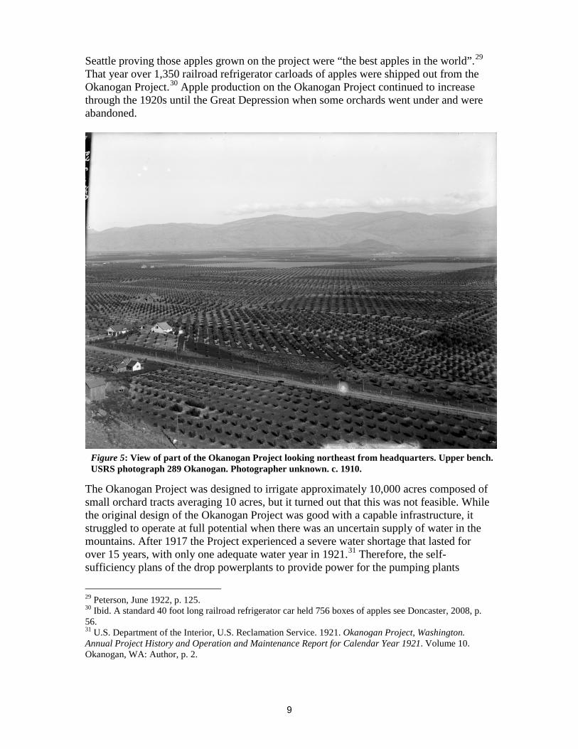
Upper Main Lateral) and the 6 mile Lower Main Canal (a.k.a Low Line Canal or Lower Main Lateral).21 From these canals there were 14 miles of laterals, sublaterals and 12 miles of pipe.22 After 1921, work on the Okanogan Project consisted of operation and maintenance (O&M) along with replacements of worn out pipe and more canal lining with concrete. In 1923 the USRS became the United States Bureau of Reclamation today known as Reclamation. Reclamation transferred over O&M of the Okanogan Project on January 1, 1929 to the OID which had been formed in 1919.23 The OID continued the policy of lining earthen portions of the system with concrete which had not been done by Reclamation and the replacement of laterals with pipe lines when funds were available. In 1943 approximately 1,900 feet of the Upper Main Canal between check structures U55 and U57 was changed from open canal to a 27 inch pipeline. More piping occurred on the Upper Main Lateral in 1947 when 10,000 feet of the canal that looped around Duck Lake “was eliminated by the laying of 3,211 feet of 36 inch buried reinforced concrete pipe” and in 1953-1954 when 1,300 feet was replaced with a 27 inch pipeline from upstream from the Drop No. 2 Powerplant. This last piping project was also a realignment of the Upper Main Canal. At this location the canal originally followed the contour of the hill and then cascaded down in front of Drop No. 2 Powerplant in a concrete drop structure, but this was all abandoned with the piping project.24 In 1922 the Okanogan Project was touted as one of the very best USRS projects and held “the record for highest gross returns per acre of all the Government projects”.25 The principle crop of the project is apples (see Figure 5). As other intensively irrigated apple orchard areas in the Northwest the project was planted by orchardists with various apple varieties such as Delicious, Winesap, Jonathon, and Spitzenberg. The second largest crop after apples was alfalfa which was used for livestock and also common in the pre-World War II era as a cover crop in orchards. 26 Fruit trees such as peaches, apricots, and pears were also planted in the early years, but they did not stay and eventually were replaced by apple trees. 27 In 1919 there were approximately 4,300 acres in apples and approximately 1,465 acres in alfalfa with orchardists receiving an average of $436.35 per acre for their apples that year. The average yield of apples per acre was approximately 195 boxes with a box of apples weighing 40 pounds.28 The apples grown on the project received 18 prizes out of 19 entries in the Northwestern Apple Exposition in November 1921 in
21 U.S. Department of the Interior, U.S. Bureau of Reclamation, 1959, p. 4; French, Robert M. 1974. National Register of Historic Places inventory nomination form - Conconully Dam. Olympia, WA: Washington Department of Archeology and Historic Preservation, p. 4. 22 U.S. Department of the Interior, U.S. Bureau of Reclamation. March 1989. Transfer Report, Transfer of Constructed Works from Construction Status to Operation and Maintenance Rehabilitation and Betterment Program, Okanogan Irrigation District, Chief Joseph Dam Project, Washington. Boise, ID: Author, p. 1. 23U.S. Department of the Interior, U.S. Reclamation Service. 1919. Okanogan Project, Washington. Annual Project History and Operation and Maintenance Report for Calendar Year 1919. Volume 8. Okanogan, WA: Author, p. 5; U.S. Department of the Interior, U.S. Bureau of Reclamation, 1959, p. 8. 24 U.S. Department of the Interior, U.S. Bureau of Reclamation, 1959, pp. 34, 36-37 & 39. 25 Peterson, June 1922, pp. 124-125. 26 Doncaster, 2008, p. 38 ; U.S. Department of the Interior, U.S. Reclamation Service, 1919, p. 76. 27 U.S. Department of the Interior, U.S. Reclamation Service, 1916, p. 64. 28 U.S. Department of the Interior, U.S. Reclamation Service, 1919, p. 76.
9
Seattle proving those apples grown on the project were “the best apples in the world”.29 That year over 1,350 railroad refrigerator carloads of apples were shipped out from the Okanogan Project.30 Apple production on the Okanogan Project continued to increase through the 1920s until the Great Depression when some orchards went under and were abandoned.
The Okanogan Project was designed to irrigate approximately 10,000 acres composed of small orchard tracts averaging 10 acres, but it turned out that this was not feasible. While the original design of the Okanogan Project was good with a capable infrastructure, it struggled to operate at full potential when there was an uncertain supply of water in the mountains. After 1917 the Project experienced a severe water shortage that lasted for over 15 years, with only one adequate water year in 1921.31 Therefore, the self-sufficiency plans of the drop powerplants to provide power for the pumping plants
29 Peterson, June 1922, p. 125. 30 Ibid. A standard 40 foot long railroad refrigerator car held 756 boxes of apples see Doncaster, 2008, p. 56. 31 U.S. Department of the Interior, U.S. Reclamation Service. 1921. Okanogan Project, Washington. Annual Project History and Operation and Maintenance Report for Calendar Year 1921. Volume 10. Okanogan, WA: Author, p. 2.
Figure 5: View of part of the Okanogan Project looking northeast from headquarters. Upper bench. USRS photograph 289 Okanogan. Photographer unknown. c. 1910.

10
proved not to be feasible as they received their water only from the canal system. Additionally, Salmon Lake Dam was built as a means to enlarge the existing Salmon Lake, but due to the drought it did not fill until 1938 and it was not until 1942 that it finally filled to its designed capacity. During this drought, orchardists drilled private wells in order to keep the orchards from dying.32 Those areas which were poor soil were abandoned and the irrigable acreage was finally reduced to 5,032 acres after OID had taken over O&M of the project, with real number acres irrigated being less than this amount. 33 Nonetheless, the highest return from apples in the Okanogan Project was in 1946; when 3,966 irrigated acres yielded a total crop value of $2,798,016, a crop value of $705.52 per acre.34 By 1948 there were eleven employees on the OID payroll for the Okanogan Project. Some, like the manager were year-round while others, such as ditchriders worked just during the irrigation season for approximately five months out of the year. Five ditchriders and two maintenance personnel were needed to operate the system including the 400 turnouts for farm delivery of water. The ditchriders would work on preparing the system for use each year and cleanup after the season was over, besides their normal beat.35 While the ditchriders were primarily men, women had been employed during World War I to run the Robinson Flat Pumping Plant and by 1959 three of the four ditchriders working for OID were women “as an economy measure because they will accept employment for irrigation season only and return each year”.36 In 1983 OID signed a rehabilitation and betterment contract with Reclamation for rehabilitating the canal system. In this project the 6.4 miles total of the Main Canal and Upper Main Canal lining was replaced, the 6 mile Low Line Canal was abandoned and piped and the original Duck Lake Pumping Plant was replaced by 1986.37 Also four new diversion structures were built in the canal system that connected to the new pressurized distribution system which has four relief and 13 booster pump stations within it.38 In 1984 the Okanogan Project was determined eligible for the National Register as a historic district being the first irrigation project in the State of Washington authorized by the USRS. Ten years prior Conconully Dam was also listed individually on the National Register.39 32 Yates, 1968, pp. 84, 85, 90 & 99. 33 U.S. Department of the Interior, U.S. Bureau of Reclamation, 1979, pp. iii-iv & 1; U.S. Department of the Interior, U.S. Bureau of Reclamation, c. 1948, p. 3. 34 Yates, 1968, pp. 123-124. 35 U.S. Department of the Interior, U.S. Bureau of Reclamation, c. 1948, p. 5. 36 Doncaster, Kelsey. 2012. Washington State Level II Historic Documentation Robinson Flat Pumping Plant, Okanogan Project. Yakima, WA: U.S. Department of the Interior, U.S. Bureau of Reclamation, Columbia-Cascades Area Office, p. 7; U.S. Department of the Interior, U.S. Bureau of Reclamation. 1963. Annual Project History and Operation and Maintenance by Okanogan Irrigation District for Years 1960-1963. Volume 19. Okanogan, WA: Author, p. 29. 37 U.S. Department of the Interior, U.S. Bureau of Reclamation. 1989. 1989 Review of Operation and Maintenance Examination of Irrigation Facilities, Okanogan Irrigation District, Okanogan Project, Washington. Boise, ID: Author, pp. 2 & 17. 38 U.S. Department of the Interior, U.S. Bureau of Reclamation, March 1989, pp. 2 &3. 39 Simmons, Alexy. 1984. Request for Determination of Eligibility Okanogan Project. Olympia, WA: Washington Department of Archeology and Historic Preservation, pp. 1-4.
11
See A Pioneer Project (Yates, 1968) and http://www.usbr.gov/dataweb/html/okanogan1.html for more information about the Okanogan Project.
Original Built Features of the Okanogan Project
Conconully Dam (1906-1910)
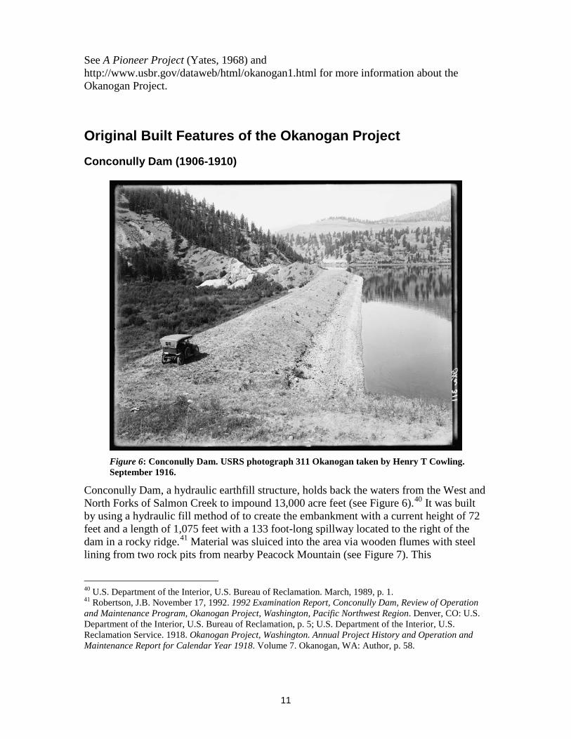
Conconully Dam, a hydraulic earthfill structure, holds back the waters from the West and North Forks of Salmon Creek to impound 13,000 acre feet (see Figure 6).40 It was built by using a hydraulic fill method of to create the embankment with a current height of 72 feet and a length of 1,075 feet with a 133 foot-long spillway located to the right of the dam in a rocky ridge.41 Material was sluiced into the area via wooden flumes with steel lining from two rock pits from nearby Peacock Mountain (see Figure 7). This
40 U.S. Department of the Interior, U.S. Bureau of Reclamation. March, 1989, p. 1. 41 Robertson, J.B. November 17, 1992. 1992 Examination Report, Conconully Dam, Review of Operation and Maintenance Program, Okanogan Project, Washington, Pacific Northwest Region. Denver, CO: U.S. Department of the Interior, U.S. Bureau of Reclamation, p. 5; U.S. Department of the Interior, U.S. Reclamation Service. 1918. Okanogan Project, Washington. Annual Project History and Operation and Maintenance Report for Calendar Year 1918. Volume 7. Okanogan, WA: Author, p. 58.
Figure 6: Conconully Dam. USRS photograph 311 Okanogan taken by Henry T Cowling. September 1916.

12
construction was very similar to hydraulic mining. Therefore the USRS had Lars Bergsvik who had worked previously in hydraulic mining to be the construction engineer to guide other USRS engineers and laborers in the construction of Conconully Dam. The outlet tunnel was blasted out of the granite and the spillway was built of concrete. It was the first USRS dam built by hydraulic methods and it is the only USRS or Reclamation built dam with this method and composition in Washington State. 42
Conconully Dam is composed of over 359,000 cubic yards of rock and dirt material.43 Due to the construction of Conconully Dam the embankment has been modified because of seepage issues several times since its original construction. It was raised in 1919-1920 by 2.5 feet then rehabilitated in 1951-1952 in strengthening of its embankment and the inlet for the spillway.44 In 1958 more riprap was added to the upstream side and in 1959 auxiliary gates were installed within the dam’s outlet.45 The last change was in 1968-1969 when a stability berm was added to the downstream face and the crest was raised by
42 Autobee, Robert. 1996. Okanogan Project. Denver, CO: U.S. Department of the Interior, U.S. Bureau of Reclamation, p. 8. 43 U.S. Department of the Interior, U.S. Bureau of Reclamation, 1959, p. 4. 44 U.S. Department of the Interior, U.S. Bureau of Reclamation, March 1989, p. 2; Yates, 1968, p. 91; Fowler, R.W. & Harber, W.G. 1961. Condition of Conconully Dam, Okanogan Project, Washington. Denver, CO: U.S. Department of the Interior, U.S. Bureau of Reclamation, p. 3; U.S. Department of the Interior, U.S. Reclamation Service, 1919, p. 63. 45 U.S. Department of the Interior, U.S. Bureau of Reclamation, 1959, p. 7.
Figure 7: Conconully Dam; separated material dropping into dam. Okanogan Project, WA. USRS photograph 173 Okanogan by Frank S. Matsura. June 28, 1908.

13
1.5 feet.46 Also from 1968-1969 the original concrete spillway was rebuilt with the most dramatic change being a baffle block chute on the downstream side which originally had been a straight chute (see Figures 8 & 9). This new baffle block chute spillway can handle a release of a maximum of 11,580 cubic feet per second (cfs) of water while the older spillway could only handle 6,000 cfs of outflow.47 Finally, the outlet works experienced a visible change when the original wooden portion of the gatehouse, which encloses the outlet works gate mechanisms, was torn down and replaced with cinderblock and a gable metal roof after 1964.48 See Yates, 1968 & French, 1974 for more information about Conconully Dam.
46 Robertson, 1992, p. 5; U.S. Department of the Interior, U.S. Bureau of Reclamation. 2014. Conconully Dam. Retrieved August 28, 2014 from http://www.usbr.gov. 47 U.S. Department of the Interior, U.S. Bureau of Reclamation. 2014. Conconully Dam. 48 U.S. Department of the Interior, U.S. Bureau of Reclamation. 1971. Annual Project History and Operation and Maintenance by Okanogan Irrigation District for Years 1970-1971. Volume 23. Okanogan, WA: Author, p. 4; U.S. Department of the Interior, U.S. Bureau of Reclamation. 1965. Annual Project History and Operation and Maintenance by Okanogan Irrigation District for Years 1964-1965. Volume 20. Okanogan, WA: Author, p. 30.
Figure 8: View of spillway from general panoramic view of dam from borrow pit, photo number 1 of 3. Okanogan Project, WA. Reclamation photograph P21-100-292. Photographer unknown. c. 1910.

14
Salmon Lake Dam (1918-1921) Salmon Lake Dam and Conconully Dam are both fed by the North Fork of Salmon Creek. Conconully Reservoir is fed directly and Salmon Lake Reservoir is fed via a 3,700 foot-long feeder canal/pipeline. Salmon Lake Dam is a zoned earthen embankment dam 1,260 feet long and 54 feet high and is located directly to the east of the town of Conconully that can impound 10,500 acre feet of water. Water is released from the dam in a combination outlet and spillway works into a 500 foot-long discharge channel that empties into the North Fork of Salmon Creek where it then flows into Conconully Reservoir. Conconully Dam is less than 2 miles south from Salmon Lake Dam.49 When the Okanogan Project was built Salmon Lake already existed as a natural lake.50 In 1916 an earthen dam with a concrete outlet was built to increase the storage capacity of the lake from 2,000 to 3,000 acre-feet. Later once the big Salmon Lake Dam was built, 49 U.S. Department of the Interior, U.S. Bureau of Reclamation. November 2013. Periodic Facility Review Salmon Lake Dam, Okanogan Project, Washington. Boise, ID: Author, p. 7. 50 Bonstedt, Fred. 1910. Method of Water Delivery as Practiced on the Okanogan Project, Washington During the Irrigation Seasons of 1909 & 1910 in Conference of Operating Officials on Operation and Maintenance. North Yakima, WA: U.S. Department of the Interior, U.S. Reclamation Service, p. 61.
Figure 9: Current Conconully Dam Spillway looking northwest from the bottom. Reclamation digital photograph by Kelsey Doncaster. August 25, 2010.
15
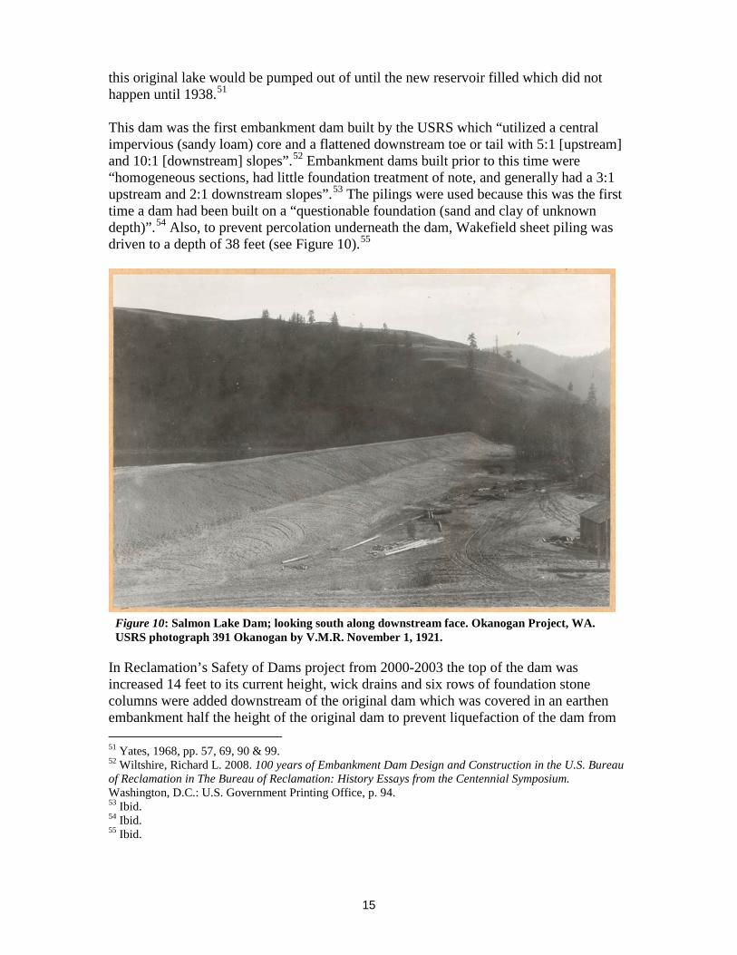
this original lake would be pumped out of until the new reservoir filled which did not happen until 1938.51 This dam was the first embankment dam built by the USRS which “utilized a central impervious (sandy loam) core and a flattened downstream toe or tail with 5:1 [upstream] and 10:1 [downstream] slopes”.52 Embankment dams built prior to this time were “homogeneous sections, had little foundation treatment of note, and generally had a 3:1 upstream and 2:1 downstream slopes”.53 The pilings were used because this was the first time a dam had been built on a “questionable foundation (sand and clay of unknown depth)”.54 Also, to prevent percolation underneath the dam, Wakefield sheet piling was driven to a depth of 38 feet (see Figure 10).55
In Reclamation’s Safety of Dams project from 2000-2003 the top of the dam was increased 14 feet to its current height, wick drains and six rows of foundation stone columns were added downstream of the original dam which was covered in an earthen embankment half the height of the original dam to prevent liquefaction of the dam from 51 Yates, 1968, pp. 57, 69, 90 & 99. 52 Wiltshire, Richard L. 2008. 100 years of Embankment Dam Design and Construction in the U.S. Bureau of Reclamation in The Bureau of Reclamation: History Essays from the Centennial Symposium. Washington, D.C.: U.S. Government Printing Office, p. 94. 53 Ibid. 54 Ibid. 55 Ibid.
Figure 10: Salmon Lake Dam; looking south along downstream face. Okanogan Project, WA. USRS photograph 391 Okanogan by V.M.R. November 1, 1921.

16
an earthquake and seepage concerns (see Figure 11).56 Also, the downstream transition of the outlet was rebuilt to include a twin bulkhead gate structure at this time. A Historic American Engineering Record (HAER) No. WA-67 was to document the dam before the work was done. Prior to the Safety of Dams work the wooden walkway to the outlet/spillway structure had been replaced several times over the years as the wood had deteriorated. Nonetheless, the concrete spillway and outlet works today remain unchanged from the original construction with the only addition being a siphon breaker pipe installed on the top of the spillway structure in 1968; this pipe was added to ensure that the water in the reservoir could not be drawn down below the top of the active water level.57 See Yates, 1968 for more information about Salmon Lake Dam.
56 Reclamation’s Safety of Dams Program was created in 1976 in response to the Teton Dam failure in Idaho. Each dam within the agency is periodically reviewed and from these examinations dam’s that could be in danger of failure are corrected to cease such possibilities. See http://www.usbr.gov/pn/about/dams/sod.html for more information. 57 U.S. Department of the Interior, U.S. Bureau of Reclamation, November 2013, p. 7; U.S. Department of the Interior, U.S. Bureau of Reclamation. 1938. Dams and Control Works: A Description of Representative Storage and Diversion Dam and High-Pressure Reservoir Outlet Works Constructed by the Bureau of Reclamation. Washington D.C.: U.S. Government Printing Office, p. 259.
Figure 11: Salmon Lake Dam, looking south along downstream face from Silver Street. Compare with historic photo in Figure 10. Reclamation digital photograph by Kelsey Doncaster. August 24, 2010.

17
Salmon Creek Diversion Dam (1906)
This diversion dam was built from September 26, 1906 to November 28, 1906 and is located 12 miles downstream of Conconully Dam in Salmon Creek.58 The 140 foot-long dam is a poured-in-place reinforced concrete ogee type weir diversion that stretches across the creek to hold back water so it can be diverted into the Okanogan Project’s Main Canal (see Figure 12). On the left downstream side are the headworks for the Main Canal which today are composed of a metal gate and concrete abutments on either side. The diversion dam remained unchanged until 1962 when a slot for sluicing out sand was cut into the concrete ogee weir.59 The headgate used to control water into the Main Canal was originally a 6 foot wide slot where wooden flashboards were slipped down to control the flow of water into the canal. Sometime after 1929 this was changed to a wooden gate that was raised and lowered by a hand cranked rack and pinion device that sat on top of timbers above the concrete opening (see Figure 13).60 It remained this way until 1971 when the gate hoist mechanism was enclosed to protect it.61 Updates since that time include a new metal gate, sluice gate and replacement of worn out concrete from 1976-
58 U.S. Department of the Interior, U.S. Reclamation Service, 1913, pp. 77-78. 59 Date is determined from comparing photographs in the U.S. Department of the Interior, U.S. Bureau of Reclamation, 1963, pp. 35 & 44 that were taken in 1961 & 1963. 60 U.S. Department of the Interior, U.S. Bureau of Reclamation, 1963, pp. viii & 35. 61 U.S. Department of the Interior, U.S. Bureau of Reclamation, 1971, p. 25.
Figure 12: Diversion Weir [Salmon Creek Diversion Dam] looking upstream. Okanogan Project, WA. USRS photograph 92 Okanogan by Frank S. Matsura. June 1, 1907.

18
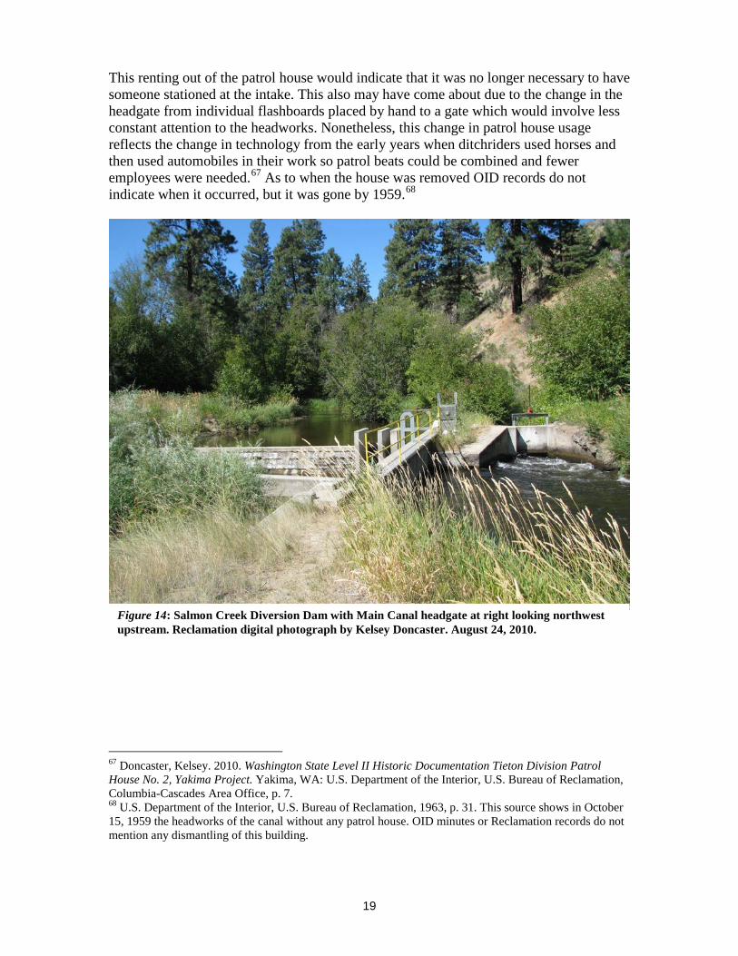
1985.62 Then in 1999-2000 the Salmon Creek Diversion Dam was modified for fish passage with a step pool weir ladder and HAER No. WA-68 was completed to document the dam before the work was done.63 This modification involved the placement of three concrete weirs of various heights which would create series of pools so that the fish could move up over the dam. Additionally, it was built for both high and low water so it also had a vertical notch cut in the dam and installed in the each of the three weirs (see Figure 14).64
A patrol house was built in 1909 at the Salmon Creek Diversion Dam on the left downstream side for someone to “be constantly at duty at the intake of the canal” (see Figure 15).65 Reclamation records indicate that this was the only patrol house built on the project. It was in use by both Reclamation and OID until 1931 when it was rented out.66
62 Emerson, Stephen. 2001. Salmon Creek Diversion Dam and Headworks, Historic American Engineering Record No. WA-68. Cheney, WA: Archeological and Historical Services, p. 12. 63 While this HAER WA-68 contains good information, it also has many inaccuracies such as the history of the patrol house which in the HAER is describing the Manager’s house at the headquarters office [which burned in 1931] not the house at the diversion dam. 64 Emerson, 2001, p. 2. 65 U.S. Department of the Interior, U.S. Reclamation Service, 1913, p. 91. 66 Minutes of the Okanogan Irrigation District, Volume 1, December 1928 to October, 1944, Minutes from May 5, 1931.
Figure 13: Headgate of the Main Canal with a wide section downstream to collect sand and keep it out of the canal system. Note that the patrol house in Figure 14 is now gone. Reclamation photograph P21-100-97. Photographer unknown. August 22, 1961.
19
This renting out of the patrol house would indicate that it was no longer necessary to have someone stationed at the intake. This also may have come about due to the change in the headgate from individual flashboards placed by hand to a gate which would involve less constant attention to the headworks. Nonetheless, this change in patrol house usage reflects the change in technology from the early years when ditchriders used horses and then used automobiles in their work so patrol beats could be combined and fewer employees were needed.67 As to when the house was removed OID records do not indicate when it occurred, but it was gone by 1959.68
67 Doncaster, Kelsey. 2010. Washington State Level II Historic Documentation Tieton Division Patrol House No. 2, Yakima Project. Yakima, WA: U.S. Department of the Interior, U.S. Bureau of Reclamation, Columbia-Cascades Area Office, p. 7. 68 U.S. Department of the Interior, U.S. Bureau of Reclamation, 1963, p. 31. This source shows in October 15, 1959 the headworks of the canal without any patrol house. OID minutes or Reclamation records do not mention any dismantling of this building.
Figure 14: Salmon Creek Diversion Dam with Main Canal headgate at right looking northwest upstream. Reclamation digital photograph by Kelsey Doncaster. August 24, 2010.
20
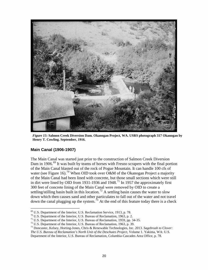
Main Canal (1906-1907) The Main Canal was started just prior to the construction of Salmon Creek Diversion Dam in 1906.69 It was built by teams of horses with Fresno scrapers with the final portion of the Main Canal blasted out of the rock of Pogue Mountain. It can handle 100 cfs of water (see Figure 16).70 When OID took over O&M of the Okanogan Project a majority of the Main Canal had been lined with concrete, but those small sections which were still in dirt were lined by OID from 1931-1936 and 1948.71 In 1957 the approximately first 300 feet of concrete lining of the Main Canal were removed by OID to create a settling/stilling basin built in this location.72 A settling basin causes the water to slow down which then causes sand and other particulates to fall out of the water and not travel down the canal plugging up the system.73 At the end of this feature today there is a check 69 U.S. Department of the Interior, U.S. Reclamation Service, 1913, p. 78. 70 U.S. Department of the Interior, U.S. Bureau of Reclamation, 1963, p. 2. 71 U.S. Department of the Interior, U.S. Bureau of Reclamation, 1959, pp. 34-35. 72 U.S. Department of the Interior, U.S. Bureau of Reclamation, 1963, p. 39. 73 Doncaster, Kelsey, Horting-Jones, Chris & Renewable Technologies, Inc. 2013. Sagebrush to Clover: The U.S. Bureau of Reclamation’s North Unit of the Deschutes Project, Volume 1. Yakima, WA: U.S. Department of the Interior, U.S. Bureau of Reclamation, Columbia-Cascades Area Office, p. 78.
Figure 15: Salmon Creek Diversion Dam. Okanogan Project, WA. USRS photograph 317 Okanogan by Henry T. Cowling. September, 1916.

21
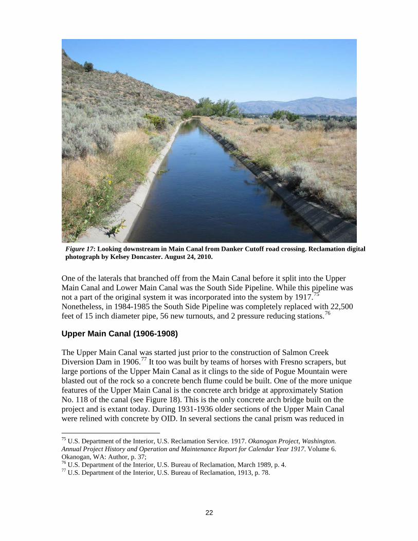
structure with trashrack that replaced both an original check structure and trashrack structure in the 1984-1987 rehabilitation. Then after the check/trashrack the canal resumes its concrete prism for another 175 feet until it comes to a fish screen. The fish screen facility was installed in 1984-1985. Also, turnouts were replaced in the 1984-1987 rehabilitation, but the survey did not evaluate all of the turnouts so there still may be some original ones in use or on the abandoned portions of the system.74 While the canal was relined it was done in concrete and it still has its historic shape and form (see Figure 17).
74 U.S. Department of the Interior, U.S. Bureau of Reclamation, March 1989, pp. 3 & 5.
Figure 16: Station [No]. 36, Main Canal, looking downstream. Okanogan Project, WA. USRS photograph 84 Okanogan by Frank S. Matsura. May 31, 1907.
22
One of the laterals that branched off from the Main Canal before it split into the Upper Main Canal and Lower Main Canal was the South Side Pipeline. While this pipeline was not a part of the original system it was incorporated into the system by 1917.75 Nonetheless, in 1984-1985 the South Side Pipeline was completely replaced with 22,500 feet of 15 inch diameter pipe, 56 new turnouts, and 2 pressure reducing stations.76
Upper Main Canal (1906-1908) The Upper Main Canal was started just prior to the construction of Salmon Creek Diversion Dam in 1906.77 It too was built by teams of horses with Fresno scrapers, but large portions of the Upper Main Canal as it clings to the side of Pogue Mountain were blasted out of the rock so a concrete bench flume could be built. One of the more unique features of the Upper Main Canal is the concrete arch bridge at approximately Station No. 118 of the canal (see Figure 18). This is the only concrete arch bridge built on the project and is extant today. During 1931-1936 older sections of the Upper Main Canal were relined with concrete by OID. In several sections the canal prism was reduced in
75 U.S. Department of the Interior, U.S. Reclamation Service. 1917. Okanogan Project, Washington. Annual Project History and Operation and Maintenance Report for Calendar Year 1917. Volume 6. Okanogan, WA: Author, p. 37; 76 U.S. Department of the Interior, U.S. Bureau of Reclamation, March 1989, p. 4. 77 U.S. Department of the Interior, U.S. Bureau of Reclamation, 1913, p. 78.
Figure 17: Looking downstream in Main Canal from Danker Cutoff road crossing. Reclamation digital photograph by Kelsey Doncaster. August 24, 2010.

23
size by this lining as the larger sized canal was no longer needed with a reduction in irrigable acreage. In 1943 and 1953 two sections of the Upper Main Canal were piped. By 1959 the flume on this canal had been replaced also.78 The in 1963 the OID purchased the Omak Pump Company pumping plant on the Okanogan River at Shellrock Point between Omak and Okanogan. This plant had been built in 1930 by farmers to bring more water into the Okanogan Project. The discharge from this plant emptied into the Upper Main Canal.79 It was completely replaced with a new four pump plant built upon the old foundation and larger 30 inch discharge line in 1977-1979. Today it is known as the Shellrock Pumping Plant.80
In the 1984-1987 rehabilitation portions of the canal were raised in sections and relined with a 3-inch thick reinforced concrete. Nonetheless, it does not diminish its integrity as it still has its historic shape and form (see Figures 19 & 20). One section along Pogue Mountain although relined was not raised and therefore it still has its original 1907 78 U.S. Department of the Interior, U.S. Bureau of Reclamation, 1959, pp. 4 & 33-35. 79 U.S. Department of the Interior, U.S. Bureau of Reclamation, 1959, p. 8; U.S. Department of the Interior, U.S. Bureau of Reclamation, 1963, p. 40. 80 U.S. Department of the Interior, U.S. Bureau of Reclamation. 1977. Project History Okanogan Project, Washington 1976-1977. Volume 26. Okanogan, WA: Author, p. N2 & 103; U.S. Department of the Interior, U.S. Bureau of Reclamation, 1979, p. 60. Other Reclamation archival sources also have Shellrock spelled as Shell Rock or Shellrock, but for this document Shellrock is used as that is what is on the USGS Omak Quad.
Figure 18: [Upper] Main Canal. Concrete lined canal Station [No] 118. Okanogan Project, WA. Note concrete arch bridge that man is standing on. USRS photograph 129 Okanogan by Frank S. Matsura. October 19, 1907.
24
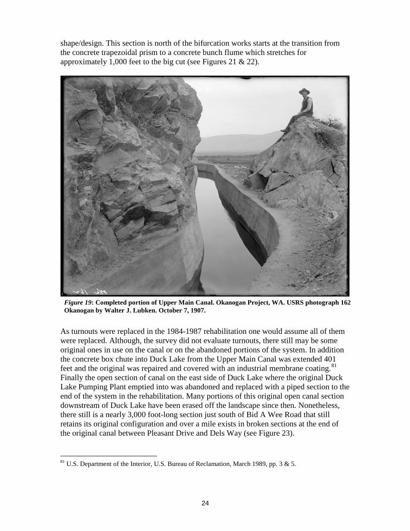
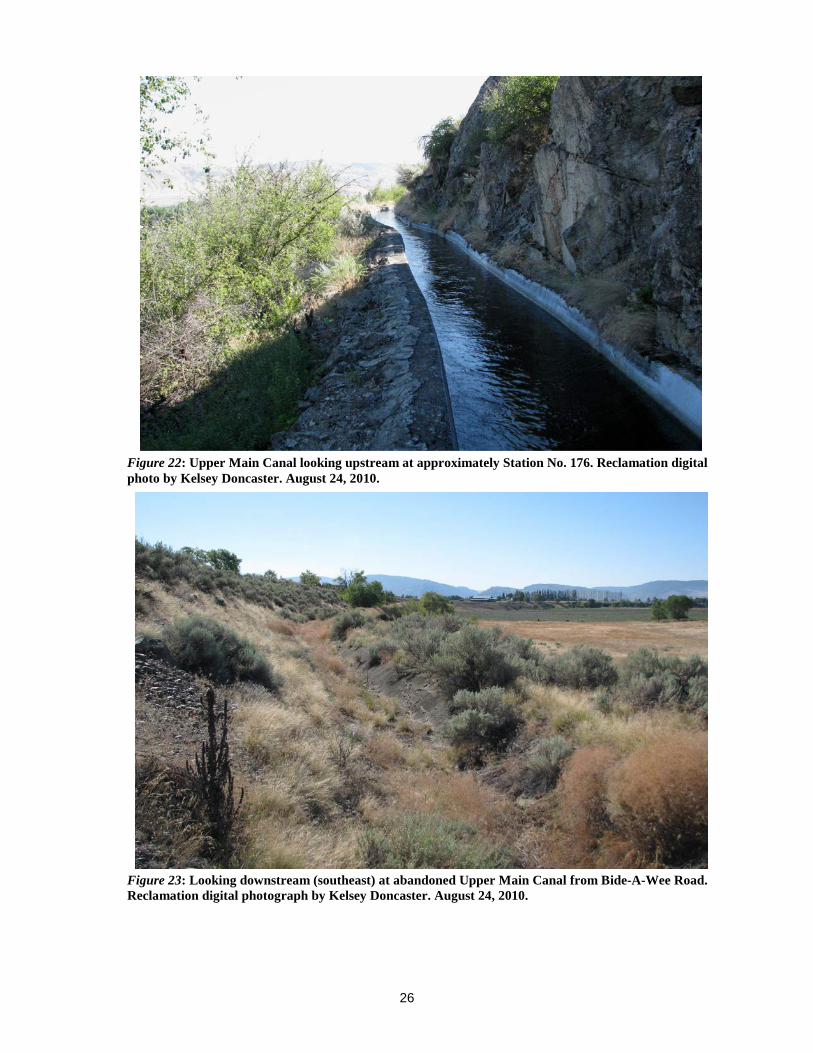
shape/design. This section is north of the bifurcation works starts at the transition from the concrete trapezoidal prism to a concrete bunch flume which stretches for approximately 1,000 feet to the big cut (see Figures 21 & 22).
As turnouts were replaced in the 1984-1987 rehabilitation one would assume all of them were replaced. Although, the survey did not evaluate turnouts, there still may be some original ones in use on the canal or on the abandoned portions of the system. In addition the concrete box chute into Duck Lake from the Upper Main Canal was extended 401 feet and the original was repaired and covered with an industrial membrane coating.81 Finally the open section of canal on the east side of Duck Lake where the original Duck Lake Pumping Plant emptied into was abandoned and replaced with a piped section to the end of the system in the rehabilitation. Many portions of this original open canal section downstream of Duck Lake have been erased off the landscape since then. Nonetheless, there still is a nearly 3,000 foot-long section just south of Bid A Wee Road that still retains its original configuration and over a mile exists in broken sections at the end of the original canal between Pleasant Drive and Dels Way (see Figure 23).
81 U.S. Department of the Interior, U.S. Bureau of Reclamation, March 1989, pp. 3 & 5.
Figure 19: Completed portion of Upper Main Canal. Okanogan Project, WA. USRS photograph 162 Okanogan by Walter J. Lubken. October 7, 1907.

25
Figure 21: [Upper] Main Canal. Concrete lined canal. Okanogan Project, WA. USRS photograph 124 Okanogan by Frank S. Matsura. October 19, 1907.
Figure 20: Upper Main Canal at same location of historic photo 162 Okanogan (Figure 19). Reclamation digital photograph by Kelsey Doncaster. August 24, 2010.
26
Figure 22: Upper Main Canal looking upstream at approximately Station No. 176. Reclamation digital photo by Kelsey Doncaster. August 24, 2010.
Figure 23: Looking downstream (southeast) at abandoned Upper Main Canal from Bide-A-Wee Road. Reclamation digital photograph by Kelsey Doncaster. August 24, 2010.

27
Lower Main Canal (1906-1908)
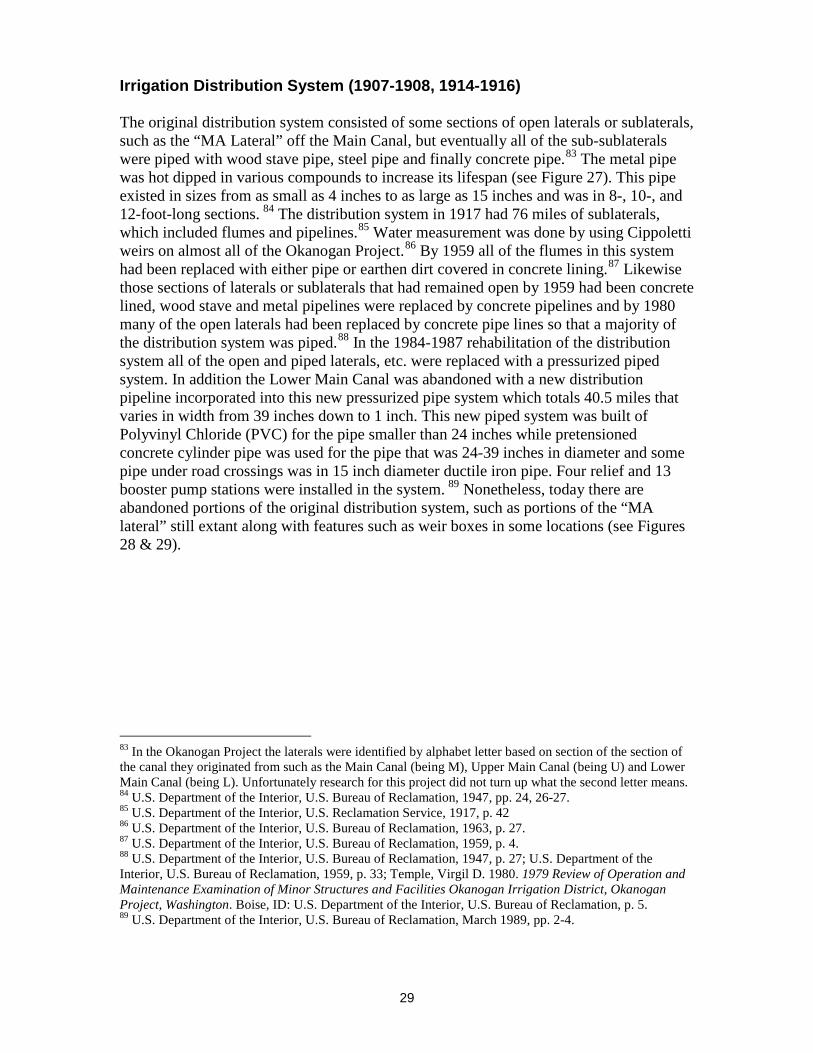
The Lower Main Canal was also constructed the same time as the Upper Main Canal and was completed in the same manner with teams of horses used to excavate out the lateral from the dirt as it made its way along Pogue Flat and around Omak to Robinson Flat. The most dramatic part of the Lower Main Canal was the 105 foot drop from the Main Canal down Pogue Mountain (see Figures 24 & 25). In the 1984-1987 rehabilitation the open Lower Main Canal was abandoned and portions of it were incorporated into the new pressurized pipe system.82 Due to this change/modification the Lower Main Canal only exists in small segments as most of it was obliterated in the new pressurized pipe system. The original diversion structure for the Lower Main Canal was reconfigured in this rehabilitation to just be a turnout and the weir for the Drop No. 1 Powerplant was removed. Although, the first part of the original Lower Main Canal exists intact from the Main Canal through its concrete chute (now covered) past the abandoned Drop No. 1 Powerplant through the Okanogan Valley Golf Club to just south of the Reclamation Pond and then it is extant again along the pond to just south of the Headquarters complex. The latter portion is unused, but the portion through the Okanogan Valley Golf Club is functional although rarely used (see Figure 26). Also between Duck Lake Road and 82 U.S. Department of the Interior, U.S. Bureau of Reclamation, March 1989, p. 2.
Figure 24: Drop No. 1, from Main Upper Canal to Lower Canal, Pogue Flat. Okanogan Project, WA. USRS photograph 163 Okanogan by Walter J. Lubken. October 7, 1907.
28
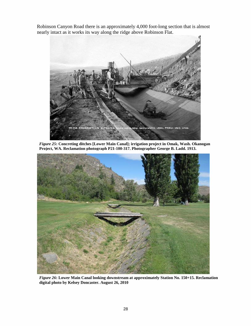
Robinson Canyon Road there is an approximately 4,000 foot-long section that is almost nearly intact as it works its way along the ridge above Robinson Flat.
Figure 25: Concreting ditches [Lower Main Canal]; irrigation project in Omak, Wash. Okanogan Project, WA. Reclamation photograph P21-100-317. Photographer George B. Ladd. 1913.
Figure 26: Lower Main Canal looking downstream at approximately Station No. 150+15. Reclamation digital photo by Kelsey Doncaster. August 26, 2010
29
Irrigation Distribution System (1907-1908, 1914-1916) The original distribution system consisted of some sections of open laterals or sublaterals, such as the “MA Lateral” off the Main Canal, but eventually all of the sub-sublaterals were piped with wood stave pipe, steel pipe and finally concrete pipe.83 The metal pipe was hot dipped in various compounds to increase its lifespan (see Figure 27). This pipe existed in sizes from as small as 4 inches to as large as 15 inches and was in 8-, 10-, and 12-foot-long sections. 84 The distribution system in 1917 had 76 miles of sublaterals, which included flumes and pipelines.85 Water measurement was done by using Cippoletti weirs on almost all of the Okanogan Project.86 By 1959 all of the flumes in this system had been replaced with either pipe or earthen dirt covered in concrete lining.87 Likewise those sections of laterals or sublaterals that had remained open by 1959 had been concrete lined, wood stave and metal pipelines were replaced by concrete pipelines and by 1980 many of the open laterals had been replaced by concrete pipe lines so that a majority of the distribution system was piped.88 In the 1984-1987 rehabilitation of the distribution system all of the open and piped laterals, etc. were replaced with a pressurized piped system. In addition the Lower Main Canal was abandoned with a new distribution pipeline incorporated into this new pressurized pipe system which totals 40.5 miles that varies in width from 39 inches down to 1 inch. This new piped system was built of Polyvinyl Chloride (PVC) for the pipe smaller than 24 inches while pretensioned concrete cylinder pipe was used for the pipe that was 24-39 inches in diameter and some pipe under road crossings was in 15 inch diameter ductile iron pipe. Four relief and 13 booster pump stations were installed in the system. 89 Nonetheless, today there are abandoned portions of the original distribution system, such as portions of the “MA lateral” still extant along with features such as weir boxes in some locations (see Figures 28 & 29).
83 In the Okanogan Project the laterals were identified by alphabet letter based on section of the section of the canal they originated from such as the Main Canal (being M), Upper Main Canal (being U) and Lower Main Canal (being L). Unfortunately research for this project did not turn up what the second letter means. 84 U.S. Department of the Interior, U.S. Bureau of Reclamation, 1947, pp. 24, 26-27. 85 U.S. Department of the Interior, U.S. Reclamation Service, 1917, p. 42 86 U.S. Department of the Interior, U.S. Bureau of Reclamation, 1963, p. 27. 87 U.S. Department of the Interior, U.S. Bureau of Reclamation, 1959, p. 4. 88 U.S. Department of the Interior, U.S. Bureau of Reclamation, 1947, p. 27; U.S. Department of the Interior, U.S. Bureau of Reclamation, 1959, p. 33; Temple, Virgil D. 1980. 1979 Review of Operation and Maintenance Examination of Minor Structures and Facilities Okanogan Irrigation District, Okanogan Project, Washington. Boise, ID: U.S. Department of the Interior, U.S. Bureau of Reclamation, p. 5. 89 U.S. Department of the Interior, U.S. Bureau of Reclamation, March 1989, pp. 2-4.

30
Figure 27: Laying 12" iron pipe for Extension of Distribution System - showing method of laying pipe and dipping end for joining on UA Lateral near Riverside, Wash. Okanogan Project, WA. USRS photograph P21-100-320 taken by Calvin Casteel. May 18, 1914.

31
Figure 28: Smallest weir on Okanogan Project located on Robinson Flat area. August 22, 1961. Reclamation photograph P21-100-101. Photographer unknown.
Figure 29: Abandoned weir box on Glover Lane Road. Reclamation photo by Kelsey Doncaster. August 25, 2010.

32
Duck Lake Pumping Plant (1919)
Duck Lake Pumping Plant was built 1919 to provide additional water to the Upper Main Canal for watering 620 acres.90 It was an incline pumping plant that rose up and down on wheels with the lake level via a wooden tramway with metal rails on it (see Figure 30). It had a 12 inch metal pipe screened intake that would then pump water up between 30 and 70 feet into the Upper Main Canal depending on the lake level.91 Additional smaller pumping plants were built and removed over the years, but the incline plant is what stayed from its inception. On September 13, 1921 this pumping plant burned to the ground, but was rebuilt in time for the 1922 season, the wooden enclosure around the pump may have been completely clad in corrugated metal at this time.92 Certainly by the 1950s it was completely clad in corrugated metal. The pump was originally powered by an internal combustion engine, but it was electrified in 1922 with a 50 horse power (HP) motor to a 10 inch horizontal pump and a 5.07 mile transmission line was built to it.93 Pumps within it were first gasoline and later electric, but were replaced over the years
90 Yates, 1968, p. 62. 91 U.S. Department of the Interior, U.S. Bureau of Reclamation, 1963, p. 2. 92 U.S. Department of the Interior, U.S. Reclamation Service. 1921, p. XI; U.S. Department of the Interior, U.S. Reclamation Service. 1922, p. 3. 93 Weymouth, F.E. 1922. Letter to Chief Engineer regarding Duck Lake Pumping Plant, March 14, 1922. From Okanogan Irrigation District Files; U.S. Department of the Interior, U.S. Reclamation Service. 1922, pp. VIII, 3, 29 & 45.
Figure 30: Looking west at Duck Lake Pumping Plant. The men have just lowered the plant and are installing a section of discharge line. The plant is on rails and must be lowered periodically during the irrigation season. Okanogan Unit, Okanogan-Similkameen Division, Chief Joseph Dam Project. Reclamation photograph by H. E. Geren. May 14, 1964

33
when they burned out. In 1959 the pumping plant had a 10 cfs Allis Chalmers pump connected to a 125 HP motor.94 The 16 inch metal discharge pipe that stretched from the pumping plant to the Upper Main Canal was bolted together in 8 foot 3 inch sections that had to be removed or added when the pumping plant was lowered or raised. This unusual feature of the Okanogan Project lasted until c. 1984 when it was demolished and replaced by a new pump station with submersible pumps and motors in a concrete vault (see Figure 31).95
Robinson Flat Pumping Plant Robinson Flat Pumping Plant was built from 1914-1916 (see Figure 32). It pumped water directly from the Okanogan River to supplement the gravity supply when it was inadequate for irrigating the approximately 1,050 acres of Robinson Flat.96 When the pumping plant was not used water was delivered into the discharge line by gravity from the upper end via the Lower Main Canal.97 Once completed the pumping plant had two 200 HP motors that each pumped 6 cfs of water up the 188 feet to the 4,415 feet long 30-inch wood stave discharge line which emptied into the distribution system for Robinson 94 U.S. Department of the Interior, U.S. Bureau of Reclamation, 1959, p. 11. 95 U.S. Department of the Interior, U.S. Bureau of Reclamation, March 1989, p. 5. 96U.S. Department of the Interior, U.S. Reclamation Service, Thirteen Annual Report Okanogan Project, 1914, pp. 1 & 2. 97 U.S. Department of the Interior, Bureau of Reclamation, 1963, p. 3.
Figure 31: Looking west at new Duck Lake Pumping Plant. Reclamation digital photograph by Kelsey Doncaster. August 24, 2010.

34
Flat.98 In 1936 the original worn out pumping equipment was replaced and this pumping plant remained in operation until c. 1989 when it was abandoned.99 In 2009 Robinson Flat Pumping Plant was razed. See Washington State Level II Historic Documentation Robinson Flat Pumping Plant, Okanogan Project (Doncaster, 2012) for a detailed history of this pumping plant.
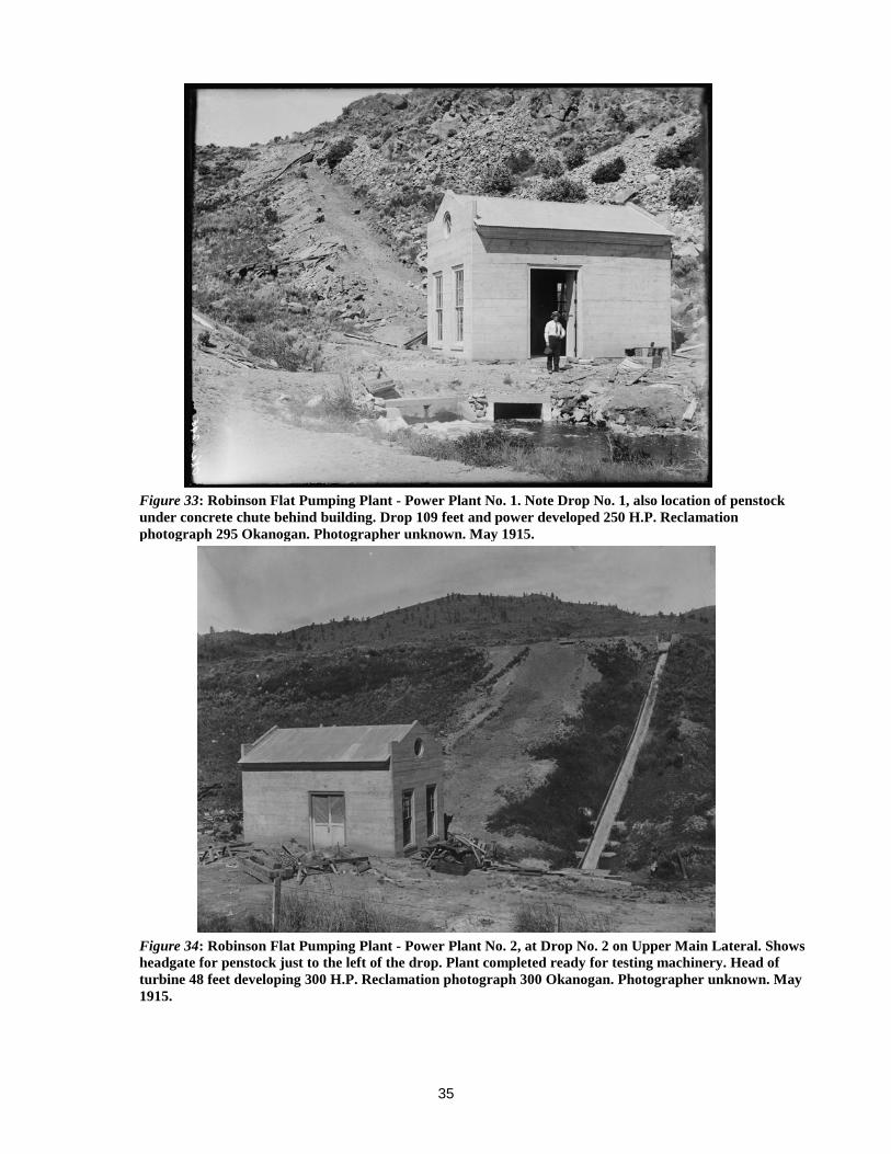
Drop No. 1 & 2 Powerplants (1914-1916) Electric power for Robinson Flat Pumping Plant was delivered by a 5.5 mile 6,600 volt transmission line from two hydro-electric powerplants one at Drop No. 1 on the Lower Main Canal and the other at Drop No. 2 on the Upper Main Canal.100 Both powerplants were built from 1914-1916 (see Figures 33 & 34). They would generate 250 HP with
98 U.S. Department of the Interior, Bureau of Reclamation, 1959, p.4. 99 Doncaster, 2012, p. 7. 100 U.S. Department of the Interior, U.S. Reclamation Service, 1918, p. 2.
Figure 32: Robinson Flat Pumping Plant on right bank of Okanogan River near town of Omak. Note steel discharge pipe connecting with wood stave pipe at top of hill, also transmission line running down to building. Plant consists of two pumping units of 6 c.f.s. capacity each. Lift to top of bench 114 feet. Total pumping lift, 177 feet. Reclamation photograph 296 Okanogan. Photographer unknown. May 1915.
35
Figure 34: Robinson Flat Pumping Plant - Power Plant No. 2, at Drop No. 2 on Upper Main Lateral. Shows headgate for penstock just to the left of the drop. Plant completed ready for testing machinery. Head of turbine 48 feet developing 300 H.P. Reclamation photograph 300 Okanogan. Photographer unknown. May 1915.
Figure 33: Robinson Flat Pumping Plant - Power Plant No. 1. Note Drop No. 1, also location of penstock under concrete chute behind building. Drop 109 feet and power developed 250 H.P. Reclamation photograph 295 Okanogan. Photographer unknown. May 1915.

36
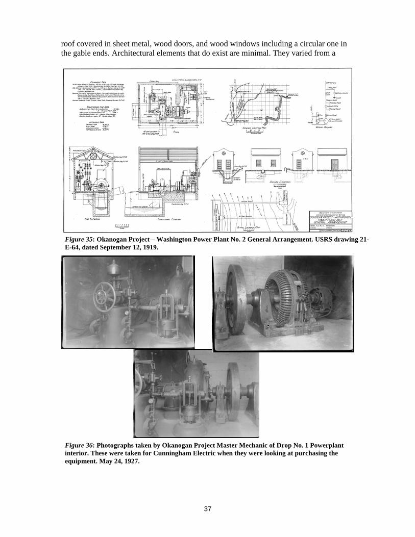
Pelton water wheels, Allis Chalmers 6,600 volt generators, Allis Chambers 125 volt exciters, General Electric switchboard and transformers (see Figures 35 & 36).101 A painted wooden telephone booth was added to complete the structures as the operators needed a quiet location to talk on the phone as these hydro-electric powerplants were very noisy. Operators could use the private telephone line installed along the transmission line to contact the Okanogan Project Headquarters Office.102 They were to be only operated when the pumping plant was needed and would provide all the power needed to run the pumping plant.103 While Drop No. 1 Powerplant only needed a working head of 27 second-feet and Drop No. 2 Powerplant needed a normal flow of 55 second-feet to operate this did not work as for many years there was not enough water to power the water wheels.104 This was not planned as the USRS had signed a power contract in 1917 to sell the power from Drop No. 1 Powerplant to the Okanogan Valley Power Company (OVPC) who would pay the USRS $300 a month as well as pay for all costs associated with the operation of the powerplant.105 By 1927 the powerplants had only run a total of nine months since they were installed during the years of 1917, 1918, 1921 and 1922.106 When there was enough water, the mechanical damage from sand eventually prevented them from generating enough power for full operation of the pumping plant.107 Eventually these powerplants were abandoned and power was supplied directly by the OVPC. A potential buyer of the electrical equipment inquired in 1927, but it is unknown if anything transpired.108 In 1928 the Washington Water and Power Company bought the electrical distribution system and substations for $12,800.109 All of the extant equipment for Drop No. 2 Powerplant was sold for $2,000 in 1931 and Drop No. 1 Powerplant’s equipment was sold for $2,400 in 1934, but the shells of the powerplants were left standing.110 The architectural style of the Drop No. 1 and Drop No. 2 are the same as Robinson Flat Pumping Plant which reflected the utilitarian style of support works in USRS/ Reclamation projects. Reinforced poured-in-place concrete walls with a metal trussed 101 Funk, W.D. 1927. Letter to Cunningham Electric Company, May 12, 1927, p. 1. From Okanogan Irrigation District Files; U.S. Department of the Interior, U.S. Bureau of Reclamation, 1915, p 64; U.S. Department of the Interior, U.S. Bureau of Reclamation, 1921, p. 59. 102Edwards, C.E. 1916. Letter to Calvin Casteel, Project Manager, March 10, 1916, p. 1. From Okanogan Irrigation District Files. This letter was regarding the 14 projects on the pumping and powerplants that had been completed by March 10, 1916. 103 U.S. Department of the Interior, U.S. Reclamation Service, 1918, p. 82. 104 U.S. Department of the Interior, U.S. Reclamation Service, 1915, p. 64. 105 U.S. Department of the Interior, U.S. Reclamation Service, 1917, p. 47. 106 Funk, 1927, p. 1; U.S. Department of the Interior, U.S. Reclamation Service, 1917, p. 4; U.S. Department of the Interior, U.S. Reclamation Service, 1918, p. 81 & Appendix Report 7-1015, U.S. Department of the Interior, U.S. Reclamation Service, 1917, p. 47. U.S. Department of the Interior, U.S. Reclamation Service, 1921, p. 42. 107 U.S. Department of the Interior, U.S. Bureau of Reclamation, 1918, p. 81. 108 See Figure 36 for the photographs taken at that time for the letter to Letter to Cunningham Electric Co, May 28, 1927, From Okanogan Irrigation District Files. 109 Royer, J.E.E. 1928. Letter to Calvin Casteel, February 13, 1928. From Okanogan Irrigation District Files. 110 Minutes of Okanogan Irrigation District, Vol. 1, pp. September 1,1931 & 137 (September 13, 1934).
37
roof covered in sheet metal, wood doors, and wood windows including a circular one in the gable ends. Architectural elements that do exist are minimal. They varied from a
Figure 35: Okanogan Project – Washington Power Plant No. 2 General Arrangement. USRS drawing 21-E-64, dated September 12, 1919.
Figure 36: Photographs taken by Okanogan Project Master Mechanic of Drop No. 1 Powerplant interior. These were taken for Cunningham Electric when they were looking at purchasing the equipment. May 24, 1927.

38
front and rear classical style cornice built of metal and parapetted ends. This style was exactly the same with other USRS pumping or power generation plants built in Washington on the Sunnyside Division of the Yakima Project.111 Records do not indicate when the raised wooden gable roof, floor, and platform frame unfinished interior was built on Drop No. 2 Powerplant, but upon investigation in 2010 it was done after 1931 when the machinery was scrapped including all of the original corrugated metal roof and steel trusses. Why it was done is unknown as nothing was found in the OID records to indicate that the district did it or if they allowed someone else remodel it that never finished it. However, it has been in its current ruinous state since 1983 based on photographs taken that year.
Headquarters Complex (1906-1923)
The Okanogan Project Headquarters was authorized for construction on April 9, 1906. The USRS had this land withdrawn from the public domain at a location that would be adjacent to the main canal and main laterals on Pogue Flat. Additionally, this location was selected because domestic water could be piped from a spring on the J. I. Pogue property.112 Pogue Flat was named for J. I. Pogue who was an early pioneer orchardist and whose house was also located near the headquarters.113 111 The Yakima Project is composed of five irrigation divisions and a storage division. The Sunnyside Division was the first one of the project. 112 U.S. Department of the Interior, U.S. Reclamation Service, 1913, pp. 24 & 25. 113 Yates, 1968, pp. 6-7.
Figure 37: Okanogan Project Headquarters looking north c. 1915. Photograph X03173 courtesy of Okanogan County Historical Society.

39
Those headquarters buildings built in 1906 were the project engineer’s house, office building, mess house, bunkhouse and a covered stable for horses. They were built for $2,500.00.114 The headquarters complex stayed the same until January 28, 1907 when a fire started in the bunkhouse and burned down it along with the mess house.115 Until the rebuilding program could begin tents were used to house employees. Frank Matsura photographs indicate that this lasted until midway through 1907. Around the spring of 1907 the bath house was added along with the vault and later the mess house was rebuilt along with a chief clerk’s cottage where the bunkhouse had been. The complex changed again in 1912 when a barn, garage for cars, blacksmith shop and a storehouse were added for the O&M of the irrigation project. In 1913 a machine shop was built, but that was replaced by a larger machine shop along with an oil house by c.1919-1923 (see Figures 37 & 38).116
Figure 39 shows the layout of the headquarters in 1926 while still under Reclamation O&M and Figure 40 shows the complex in 1945 while under OID O&M. New buildings were built by OID to the complex after older USRS buildings had been burned down or where razed in 1931, 1949, 1957 and 2011 (see Figures 41 & 42). Today those historical
114 U.S. Department of the Interior, U.S. Reclamation Service, 1913, pp. 24 & 25. 115 U.S. Department of the Interior, U.S. Reclamation Service, 1913, p. 29; Yates, 1968, p. 24. 116 U.S. Department of the Interior, U.S. Reclamation Service. 1914. Okanogan Project, Washington. Annual Project History and Operation and Maintenance Report for Calendar Year 1914. Volume 3, 1914. Okanogan, WA: Author, p. 15.
Figure 38: Reclamation project headquarters, Okanogan project, low line canal and ranch buildings of the pioneer J. I. Pogue near tall cottonwood trees in middle distance of photograph. July 1926 view of headquarters. Reclamation photo 402 Okanogan by M.R.

40
buildings no longer extant are the USRS Manager’s Cottage, Machine Shop, Office, Warehouse, Wagon Shed, Car Garages while the new OID buildings are an Office, Manager’s Residence, Machine Shop, Equipment Shed and Storage Garage.
Figure 39: View of Okanogan Project Headquarters showing layout of complex in 1927. This is part of a larger drawing where north is not shown in the excerpt, but it is to the top of this figure. Reclamation drawing No. O.P. 1450. April 5, 1927.

41
Figure 41: Okanogan Project Headquarters 2009. Photograph taken by John Bartella.
Figure 40: View of Okanogan Project Headquarters in 1949 from Sanborn Insurance Map Sheet 15. Note the changes from 1927.

42
Requirements for Eligibility for the National Register For a resource to be eligible individually to the National Register, at least one of the National Register Criteria must apply while having integrity. The four criteria are:
Figure 42: Original Okanogan Project Headquarters complex outlined in yellow in 2011. The complex consisted of the following:
1. OID Manager’s House (non-contributing) 2. Vault (contributing) 3. Bath House (contributing) 4. Chief Clerk’s House (eligible) 5. Mess House – now garage (non-contributing) 6. Oil House (contributing) 7. Barn (eligible) 8. Storehouse (non-contributing) Razed in 2011 & replaced with OID Equipment Shed. 9. OID Machine Shop (non-contributing)

43
A. . . . [Be] associated with events that have made a significant contribution to the broad patterns of our history; or
B. . . . [Be] associated with the lives of persons significant to our past; or C. . . . [E]mbody the distinctive characteristics of a type, period, or method of
construction or that represent the work of a master, or that possess high artistic values, or that represent a significant and distinguishable entity whose components may lack individual distinction; or
D. . . . [H]ave yielded, or may yield, information important to prehistory or history. (U.S. Department of the Interior, National Park Service, 1991, p. 37)
National Register Historic Districts
According to the National Register an eligible historic district will possess “a significant concentration, linkage, or continuity of sites, buildings, structures, or objects united historically or aesthetically by plan or physical development” (U.S. Department of the Interior, National Park Service, 1985, p. 1). The historic district is made up of resources that are contributing or noncontributing to the historic significance of said property. National Register definitions are as follows:
A contributing building, site, structure, or object adds to the historic architectural qualities, historic associations, or archeological values for which a property is significant because a) it was present during the period of significance, and possesses historic integrity reflecting its character at that time or is capable of yielding important information about the period, or b) it independently meets the National Register criteria.
A noncontributing building, site, structure, or object does not add to the historic architectural qualities, historic associations, or archeological values for which a property is significant because a) it was not present during the period of significance, b) due to alterations, disturbances, additions, or other changes, it no longer possesses historic integrity reflecting its character at that time or is incapable of yielding important information about the period, or c) it does not independently meet the National Register criteria (U.S. Department of the Interior, National Park Service, 1985, p. 45).
Period of Significance The significance of the Okanogan Project is that it was Reclamation’s first irrigation project in Washington State as per the determined eligible Okanogan Project National Register Historic District. The period of significance for the whole project would be from the first year of construction (1905) to when Reclamation turned over O&M to OID on January 1, 1929.117
117 U.S. Department of the Interior, Bureau of Reclamation, 1959, p. 8.

44
Determinations of Eligibility In 1984 the Okanogan Project was determined eligible to the National Register of Historic Places.118 Prior to the rehabilitation in 1984-1987 the Okanogan Project would have been eligible for the National Register as a historic district under Criteria A & C, but the modifications of the canal system since then have caused it to no longer be eligible for Criterion C because of the loss of its original integrity. Nonetheless, it is still eligible under Criterion A as a historic district for its association with growth and development of Okanogan County and specifically of the apple industry which during its period of significance was a record producing fruit district. This is what the project was designed for as the Okanogan Project “is unique in that it was constructed to deliver water to small tracts on the assumption that the lands would all be utilized for orchards and that the average size of a farm units would be 10 acres”.119 In the years since 1974 when Conconully Dam was listed on the National Register most of the individual resources were determined eligible in the project. They are as follows:
Okanogan Project
Feature Date Constructed [includes modifications]
Individually Eligible for the National Register
Contributing to the Okanogan Project National Register Historic District
National Register Criterion
Conconully Dam 1906-1910 YES YES A & C Salmon Lake Dam 1919-1921/2000-
2003 NO* YES A
Salmon Creek Diversion Dam
1906/2000 NO* YES A
Salmon Creek Diversion Dam Fish Screen
1985 NO NO N/A
Main Canal** 1906-1907 YES YES A High Line Canal** 1906-1908 YES YES A Low Line Canal –old abandoned segments**
1906-1908 NO YES A
Drop No. 1 Powerplant
1914-1915 NO YES A
Drop No. 2 Powerplant
1914-1915 NO YES A
Shellrock Pumping Plant
1977-1979 NO NO N/A
118 Doncaster, 2012, pp. 1 & 2. 119 U.S. Department of the Interior, U.S. Bureau of Reclamation, 1947, p. 24.

45
Feature Date Constructed [includes modifications]
Individually Eligible for the National Register
Contributing to the Okanogan Project National Register Historic District
National Register Criterion
Duck Lake Pumping Plant (old - razed)
1919 N/A N/A A
Duck Lake Pumping Plant (new)
1985 NO NO N/A
Headquarters Barn
1912 YES YES A & C
Headquarters Vault
1906 YES YES A & C
Headquarters Bathhouse
1907 NO YES A
Headquarters Chief Clerks Cottage
1907/1920 YES YES A
Headquarters Oil House
1923 NO YES A
Headquarters Garage – Former Mess House
1907/1980 NO NO N/A
Lateral System – new
1984-1987 NO NO N/A
Lateral System – old abandoned segments
1907-1908, 1914-1916
NO YES A
* While various features of the Okanogan Project have been determined eligible on their own merit, the results of the Safety of Dams’ modifications to Salmon Lake Dam and the Salmon Creek Diversion Dam have made both structures no longer eligible as individual resources, but only as contributing features to the historic district. ** Those sections of the canals which were originally open, but now have been piped after the period of significance are not contributing.
Criterion A
Today’s Okanogan Project Headquarters Garage (Former Mess House) lacks integrity and was determined not eligible under this Criterion in 2011. All of the other buildings and structures that are from the period of significance of the Okanogan Project that are
46
extant are eligible under Criterion A. They are eligible either on their own or as a contributing building or structure to the historic district. Those not eligible for the National Register are Shellrock Pumping Plant, Duck Lake Pumping Plant, Salmon Creek Diversion Dam Fish Screen, and the new lateral system which were built after 1977 and are not from the Okanogan Project period of significance.
Criterion B
Research has indicated that none of the features in the Okanogan Project have any association with significant historical persons.
Criterion C
Except for the Okanogan Project Headquarters Barn, Okanogan Headquarters Vault, and Conconully Dam the rest of the historic buildings and structures in the Okanogan Project are not eligible under this Criterion on their own or as a contributing building or structure to the historic district due to changes from the past 30 plus years. Nonetheless, the concrete arch bridge at approximately Station No. 118 in the Upper Main Canal would be eligible under this Criterion due to its craftsmanship and uniqueness to the whole Okanogan Project. Today’s Okanogan Project Headquarters Garage (Former Mess House) lacks integrity and was determined not eligible under this Criterion in 2011. As with Criterion A those not eligible for the National Register are Shellrock Pumping Plant, Duck Lake Pumping Plant, Salmon Creek Diversion Dam Fish Screen, and the new lateral system which were built after 1977 and not from the Okanogan Project period of significance.
Criterion D
The subject buildings and structures do not appear to likely yield information important in history beyond this documentation.
Integrity
The following elements addressing integrity are considered for the Okanogan Project Historic District as a whole composed of those historic structures and buildings which are eligible for any of the four National Register Criteria: location, setting, design, materials, workmanship, feeling and association.
Location and Setting The historic resources of the Okanogan Project have retained their original location when built. The setting of the project has remained the same as agriculture except for the area
47
around Robinson Flat near the Okanogan River which has become housing, subdivisions, hotels, and retail establishments. The setting of the headquarters complex has remained mostly the same, except for the removal of some USRS buildings over the last 108 years and the addition of replacements done by OID. In addition when the Lower Main Canal was abandoned the portion within the headquarters was filled in.
Design, Materials and Workmanship The design of the Okanogan Project was one of storage dams which delivered water to lands for irrigation via gravity through canals. While today the extant non-contributing portions of the current system deliver the water via pumps and pressurized pipe the rest of the contributing historic features still work as originally designed capturing and delivering water from the Salmon Creek Basin to project lands. While various structures in the historic district have been modified in the history of the project the materials for the most part have been the same as what the resource was originally constructed of, such as concrete. This modification would be considered “replacement in-kind” as per the Secretary of the Interior Standards for historic properties. While the project as a whole maintains a majority of its original workmanship, the individual contributing resources can vary from good workmanship, like the Headquarters Barn, to fair workmanship, like Drop No. 2 Powerplant, due to modifications over the past 30 plus years. Therefore, the Okanogan Project’s historic components have retained their design, materials, and workmanship.
Feeling and Association The feeling of the historic resources that compose the Okanogan Project is complete as they either still possess a majority of their original appearance or look such as an open canal. Likewise, the association of those historic resources is also complete as they still are a part of the project. Nonetheless, those abandoned resources that are visible such as portions of the Upper Main Canal east of Duck Lake still retain their association even though they are no longer connected to the system as they are an original component from the Okanogan Project’s period of significance.

48
Bibliography
Autobee, Robert. 1996. Okanogan Project. Denver, CO: U.S. Department of the Interior, U.S. Bureau of Reclamation. Bonstedt, Fred. 1910. Method of Water Delivery as Practiced on the Okanogan Project, Washington During the Irrigation Seasons of 1909 & 1910 in Conference of Operating Officials on Operation and Maintenance. North Yakima, WA: U.S. Department of the Interior, U.S. Reclamation Service. Casteel, Calvin. 1927. Letter to Cunningham Electric Company, May 28, 1927. From Okanogan Irrigation District Files. Doncaster, Kelsey. 2008. From Shrub Steppe to Fruit for the Nation: Historic Preservation of Washington’s Early Fruit Industry at Johnson Orchards in Yakima, Washington. Unpublished master’s thesis, Ellensburg, WA: Central Washington University. Doncaster, Kelsey. 2010. Washington State Level II Historic Documentation Tieton Division Patrol House No. 2, Yakima Project. Yakima, WA: U.S. Department of the Interior, U.S. Bureau of Reclamation, Columbia-Cascades Area Office. Doncaster, Kelsey. 2012. Washington State Level II Historic Documentation Robinson Flat Pumping Plant, Okanogan Project. Yakima, WA: U.S. Department of the Interior, U.S. Bureau of Reclamation, Columbia-Cascades Area Office. Doncaster, Kelsey, Horting-Jones, Chris & Renewable Technologies, Inc. 2013. Sagebrush to Clover: The U.S. Bureau of Reclamation’s North Unit of the Deschutes Project. Volume 1. Yakima, WA: U.S. Department of the Interior, U.S. Bureau of Reclamation, Columbia-Cascades Area Office. Edwards, C.E. 1916. Letter to Calvin Casteel, Project Manager, March 10, 1916. From Okanogan Irrigation District Files. Emerson, Stephen. 2001. Salmon Creek Diversion Dam and Headworks, Historic American Engineering Record No. WA-68. Cheney, WA: Archeological and Historical Services. Fowler, R.W. & Harber, W.G. 1961. Condition of Conconully Dam, Okanogan Project, Washington. Denver, CO: U.S. Department of the Interior, U.S. Bureau of Reclamation.

49
French, Robert M. 1974. National Register of Historic Places inventory nomination form - Conconully Dam. Olympia, WA: Washington Department of Archeology and Historic Preservation. Funk, W.D. 1927. Letter to Cunningham Electric Company, May 12, 1927. From Okanogan Irrigation District Files. Gehri, E.F. & Burrows, G.R. 1964. Condition of Conconully Dam, Okanogan Project, Washington. Boise, ID: U.S. Department of the Interior, U.S. Bureau of Reclamation. Minutes of the Okanogan Irrigation District, Volume 1, December 1928 to October, 1944. Peterson, John S. June 1922. “On the Okanogan Project” Reclamation Record. Vol. 13, Issue 6, pp. 124-125. Pfaff, Christine. 2002. Harvest of plenty: A history of the Yakima Irrigation Project, Washington. Denver, CO: U.S. Department of the Interior, U.S. Bureau of Reclamation Technical Service Center. Robertson, J.B. November 17, 1992. 1992 Examination Report, Conconully Dam, Review of Operation and Maintenance Program, Okanogan Project, Washington, Pacific Northwest Region. Denver, CO: U.S. Department of the Interior, U.S. Bureau of Reclamation. Rowley, William D. 2006. The Bureau of Reclamation: Origins and Growth to 1945. Denver, CO: U.S. Department of the Interior, U.S. Bureau of Reclamation. Royer, J.E.E. 1928. Letter to Calvin Casteel, February 13, 1928. From Okanogan Irrigation District Files. Simmons, Alexy. 1984. Request for Determination of Eligibility Okanogan Project. Olympia, WA: Washington Department of Archeology and Historic Preservation. Temple, Virgil D. 1980. 1979 Review of Operation and Maintenance Examination of Minor Structures and Facilities Okanogan Irrigation District, Okanogan Project, Washington. Boise, ID: U.S. Department of the Interior, U.S. Bureau of Reclamation. Temple, Virgil D. & Ames, Karl S. 1982. 1982 Review of Operation and Maintenance Examination of Minor Structures and Facilities Okanogan Irrigation District, Okanogan Project, Washington. Boise, ID: U.S. Department of the Interior, U.S. Bureau of Reclamation. The Weather Channel. 2014. Weather Facts for Omak and Okanogan, WA. Retrieved from www.weather.com.
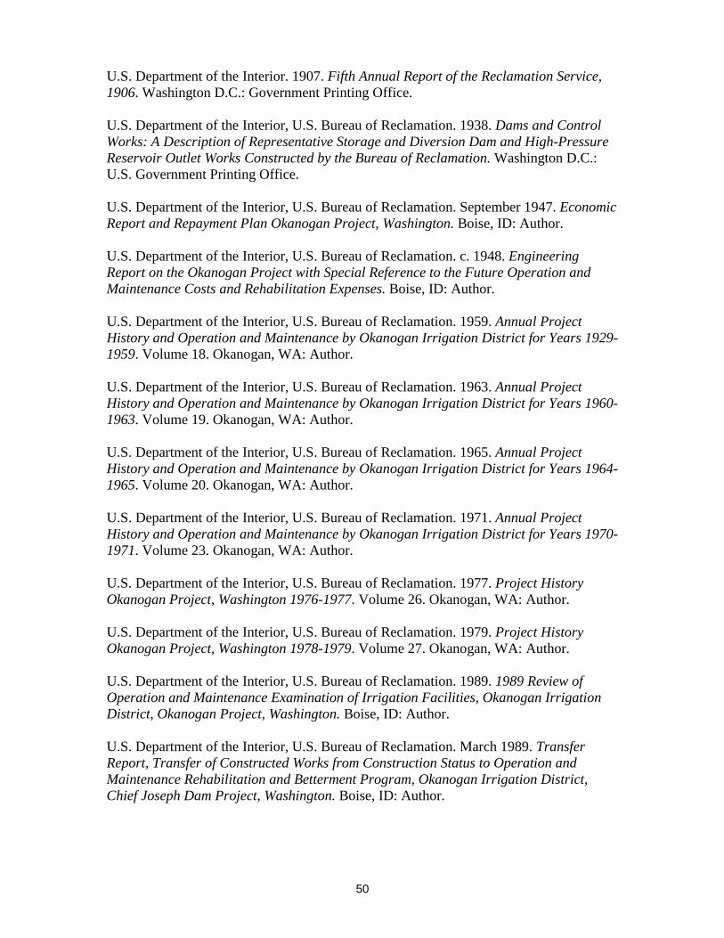
50
U.S. Department of the Interior. 1907. Fifth Annual Report of the Reclamation Service, 1906. Washington D.C.: Government Printing Office. U.S. Department of the Interior, U.S. Bureau of Reclamation. 1938. Dams and Control Works: A Description of Representative Storage and Diversion Dam and High-Pressure Reservoir Outlet Works Constructed by the Bureau of Reclamation. Washington D.C.: U.S. Government Printing Office. U.S. Department of the Interior, U.S. Bureau of Reclamation. September 1947. Economic Report and Repayment Plan Okanogan Project, Washington. Boise, ID: Author. U.S. Department of the Interior, U.S. Bureau of Reclamation. c. 1948. Engineering Report on the Okanogan Project with Special Reference to the Future Operation and Maintenance Costs and Rehabilitation Expenses. Boise, ID: Author. U.S. Department of the Interior, U.S. Bureau of Reclamation. 1959. Annual Project History and Operation and Maintenance by Okanogan Irrigation District for Years 1929-1959. Volume 18. Okanogan, WA: Author. U.S. Department of the Interior, U.S. Bureau of Reclamation. 1963. Annual Project History and Operation and Maintenance by Okanogan Irrigation District for Years 1960-1963. Volume 19. Okanogan, WA: Author. U.S. Department of the Interior, U.S. Bureau of Reclamation. 1965. Annual Project History and Operation and Maintenance by Okanogan Irrigation District for Years 1964-1965. Volume 20. Okanogan, WA: Author. U.S. Department of the Interior, U.S. Bureau of Reclamation. 1971. Annual Project History and Operation and Maintenance by Okanogan Irrigation District for Years 1970-1971. Volume 23. Okanogan, WA: Author. U.S. Department of the Interior, U.S. Bureau of Reclamation. 1977. Project History Okanogan Project, Washington 1976-1977. Volume 26. Okanogan, WA: Author. U.S. Department of the Interior, U.S. Bureau of Reclamation. 1979. Project History Okanogan Project, Washington 1978-1979. Volume 27. Okanogan, WA: Author. U.S. Department of the Interior, U.S. Bureau of Reclamation. 1989. 1989 Review of Operation and Maintenance Examination of Irrigation Facilities, Okanogan Irrigation District, Okanogan Project, Washington. Boise, ID: Author. U.S. Department of the Interior, U.S. Bureau of Reclamation. March 1989. Transfer Report, Transfer of Constructed Works from Construction Status to Operation and Maintenance Rehabilitation and Betterment Program, Okanogan Irrigation District, Chief Joseph Dam Project, Washington. Boise, ID: Author.

51
U.S. Department of the Interior, U.S. Bureau of Reclamation. 2009. Memorandum of Agreement Between the Columbia-Cascades Area Office Bureau of Reclamation and the Washington State Historic Preservation Officer and the Confederated Tribes of the Colville Reservation Regarding the Disposal of the Robinson Flat Plant Pumping Plant, Okanogan Project, Okanogan County, Washington. Yakima, WA: Author. U.S. Department of the Interior, U.S. Bureau of Reclamation. November 2013. Periodic Facility Review Salmon Lake Dam, Okanogan Project, Washington. Boise, ID: Author. Van Heeswijk, Marijke. 2006. Development of a Precipitation-Runoff Model to Simulate Unregulated Streamflow in the Salmon Creek Basin, Okanogan County, Washington. Reston, VA: U.S. Department of the Interior, U.S. Geological Survey. U.S. Department of the Interior, U.S. Bureau of Reclamation. 2014. Conconully Dam. Retrieved August 28, 2014 from http://www.usbr.gov. U.S. Department of the Interior, U.S. Reclamation Service. 1913. History of the Washington Division 1902-1913. Volume II. Okanogan Project. North Yakima, WA: Author. U.S. Department of the Interior, U.S. Reclamation Service. 1914. Okanogan Project, Washington. Annual Project History and Operation and Maintenance Report for Calendar Year 1914. Volume 3, 1914. Okanogan, WA: Author. U.S. Department of the Interior, U.S. Reclamation Service. 1915. Okanogan Project, Washington. Annual Project History and Operation and Maintenance Report for Calendar Year 1915. Volume 4. Okanogan, WA: Author. U.S. Department of the Interior, U.S. Reclamation Service. 1916. Okanogan Project, Washington. Annual Project History and Operation and Maintenance Report for Calendar Year 1916. Volume 5. Okanogan, WA: Author. U.S. Department of the Interior, U.S. Reclamation Service. 1917. Okanogan Project, Washington. Annual Project History and Operation and Maintenance Report for Calendar Year 1917. Volume 6. Okanogan, WA: Author. U.S. Department of the Interior, U.S. Reclamation Service. 1918. Okanogan Project, Washington. Annual Project History and Operation and Maintenance Report for Calendar Year 1918. Volume 7. Okanogan, WA: Author. U.S. Department of the Interior, U.S. Reclamation Service. 1919. Okanogan Project, Washington. Annual Project History and Operation and Maintenance Report for Calendar Year 1919. Volume 8. Okanogan, WA: Author.

52
U.S. Department of the Interior, U.S. Reclamation Service. 1921. Okanogan Project, Washington. Annual Project History and Operation and Maintenance Report for Calendar Year 1921. Volume 10. Okanogan, WA: Author. U.S. Department of the Interior, U.S. Reclamation Service. 1922. Okanogan Project, Washington. Annual Project History and Operation and Maintenance Report for Calendar Year 1922. Volume 11. Okanogan, WA: Author. U.S. Department of the Interior, U.S. Reclamation Service. 1914. Thirteenth Annual Report Okanogan Project. June 30, 1914. Okanogan, WA: Author. Weymouth, F.E. 1922. Letter to Chief Engineer regarding Duck Lake Pumping Plant, March 14, 1922. From Okanogan Irrigation District Files. Wiltshire, Richard L. 2008. 100 years of Embankment Dam Design and Construction in the U.S. Bureau of Reclamation in The Bureau of Reclamation: History Essays from the Centennial Symposium. Washington, D.C.: U.S. Government Printing Office. Yates, H. A. 1968. A Pioneer Project. Portland, OR: Metropolitan Press.