ols 10/15 /-c277 offline separator - start: hydac ols10-15-c277 4114093a en-us 2016-06-09.docx...
TRANSCRIPT

OLS 10/15 /-C277 OffLine Separator
Operating and Maintenance Instructions English (translation of original instructions)
Document No.: 4114093a Keep for future reference.

Imprint
OLS10/15 /-C277 en(us) Page 2 / 60
BeWa OLS10-15-C277 4114093a en-us 2016-06-09.docx 2016-06-09
Imprint
Publisher and responsible for the content: HYDAC FILTER SYSTEMS GMBH Postfach 1251 66273 Sulzbach / Saarland Germany Telephone: +49 6897 509 01 Fax: +49 6897 509 9046 E-mail: [email protected] Homepage: www.hydac.com Court of Registration: Saarbrücken, HRB 17216 Executive director: Mathias Dieter, Dipl.Kfm. Wolfgang
Haering
Documentation Representative
Mr. Günter Harge c/o HYDAC International GmbH, Industriegebiet, 66280 Sulzbach / Saar Telephone: +49 6897 509 1511 Fax: +49 6897 509 1394 E-mail: [email protected]
© HYDAC FILTER SYSTEMS GMBH
All rights reserved. No part of this work may be reproduced in any form (print, photocopy or by other means) or processed, duplicated or distributed using electronic systems without the written consent of the publisher. These documents have been created and inspected with the greatest care. However, errors cannot be ruled out completely.

Content
OLS10/15 /-C277 en(us) Page 3 / 60
BeWa OLS10-15-C277 4114093a en-us 2016-06-09.docx 2016-06-09
Content
Imprint ............................................................................................................ 2
Documentation Representative ................................................................... 2
Content .......................................................................................................... 3
Preface ........................................................................................................... 5
Technical Support ........................................................................................ 5 Product modification .................................................................................... 5 Warranty ...................................................................................................... 5 Using the documentation ............................................................................. 5
Safety information ........................................................................................ 7
Hazard symbols ........................................................................................... 7 Signal words and their meaning in the safety information and instructions .................................................................................................. 9 Structure of the safety information and instructions ..................................... 9 Proper/Designated Use ............................................................................. 10 Improper Use or Use Deviating from Intended Use ................................... 10 Qualifications of personnel / target group .................................................. 11 Wear suitable clothing ............................................................................... 12 Observe regulatory information ................................................................. 12 Stoppage in an emergency (EMERGENCY STOP) ................................... 12
Unpacking the unit ...................................................................................... 12
Transporting the unit .................................................................................. 13
Transporting with the crane ....................................................................... 13
Storing the unit ........................................................................................... 14
Decoding the name plate ........................................................................... 15
Checking the scope of delivery ................................................................. 17
Characteristics of the unit .......................................................................... 18
Coalescing procedure ................................................................................ 18
Identifying components ............................................................................. 19
Hydraulic diagram ....................................................................................... 21
Unit dimensions .......................................................................................... 22
Unit setup/connection ................................................................................ 23
Notes on pipes/hosing ............................................................................... 24 Connecting the suction port (INLET) ......................................................... 25 Checking/setting the flow rate .................................................................... 25 Connecting the pressure connection (OUTLET) ........................................ 25 Connecting the water drainage (WATER DRAIN) ..................................... 26

Content
OLS10/15 /-C277 en(us) Page 4 / 60
BeWa OLS10-15-C277 4114093a en-us 2016-06-09.docx 2016-06-09
Electrical connection of the unit ................................................................. 27 Checking the direction of rotation at the electric motor ........................... 27 Connecting the remote control line ......................................................... 28 Connection box / connect interface (optional) ........................................ 30
Connection terminals - Start/Stop external .......................................... 30 Connection terminals - Device active .................................................. 31 Connection terminals - Device OK ...................................................... 31 Connection terminals – Clogging indicator VM1, prefilter clogged ............................................................................................... 31 Connection terminals – Clogging indicator VM2, coalescing element clogged .................................................................................. 31 Remote control / Interval control Prioritization ..................................... 33
Operating / adjusting the control unit ....................................................... 34
Switching the main switch on / off .............................................................. 34 Reading LED status ................................................................................... 35 Adjusting the interval control ...................................................................... 36 Adjusting the time selector switch .............................................................. 37 Checking the motor protection switch ........................................................ 37 Switching unit on/off .................................................................................. 37 Automatic water drainage .......................................................................... 37
Starting up the unit ..................................................................................... 38
Performing maintenance ............................................................................ 40
Maintenance intervals ................................................................................ 40 Perform visual check ................................................................................. 40 Replacing hydraulic hoses ......................................................................... 41 Replacing the filter element in the filter housing ........................................ 41 Changing the coalescing elements ............................................................ 46
Status LED / Causes and remedies ........................................................... 52
Customer Service / Service ........................................................................ 55
Taking the unit out of operation ................................................................ 55
Shutting down the unit ............................................................................... 55
Disposing of the unit .................................................................................. 55
Spare parts list ............................................................................................ 55
Technical data ............................................................................................. 56
Model code .................................................................................................. 57
Index ............................................................................................................ 58

Preface
OLS10/15 /-C277 en(us) Page 5 / 60
BeWa OLS10-15-C277 4114093a en-us 2016-06-09.docx 2016-06-09
Preface
These operating instructions were made to the best of our knowledge. Nevertheless and despite the greatest care, it cannot be excluded that mistakes could have crept in. Therefore please understand that, in the absence of any provisions to the contrary hereinafter, our warranty and liability – for any legal reasons whatsoever – are excluded in respect of the information in these operating instructions. In particular, we shall not be liable for lost profit or other financial loss. This exclusion of liability does not apply in cases of intent and gross negligence. Moreover, it does not apply to defects which have been deceitfully concealed or whose absence has been guaranteed, nor in cases of culpable harm to life, physical injury and damage to health. If we negligently breach any material contractual obligation, our liability shall be limited to foreseeable damage. Claims due to Product Liability shall remain unaffected.
Technical Support Contact our technical sales department if you have any questions on our product. When contacting us, please always include the model/type designation, serial no. and article no. of the product: Fax: +49 (0) 6897 / 509 - 9046 E-mail: [email protected]
Product modification We would like to point out that changes to the product (e.g. purchasing options, etc.) may result in the information in the operating instructions no longer being completely accurate or sufficient. After modification or repair work that affects the safety of the product has been carried out on components, the product may not be returned to operation until it has been checked and released by a HYDAC technician. Please notify us immediately of any modifications made to the product whether by you or a third party.
Warranty For the warranty provided by us, please refer to the General Terms of Sale and Delivery of HYDAC FILTER SYSTEMS GMBH. You will find these under www.hydac.com -> General terms and conditions.
Using the documentation
Note that the method described for locating specific information does not release you from your responsibility of carefully reading all these instructions prior to starting the unit up for the first time

Preface
OLS10/15 /-C277 en(us) Page 6 / 60
BeWa OLS10-15-C277 4114093a en-us 2016-06-09.docx 2016-06-09
and at regular intervals in the future. What do I want to know? I determine which topic I am looking for. WHERE can I find the information I’m looking for? The documentation has a table of contents at the beginning. There, I select the chapter I'm looking for and the corresponding page number.
deHYDAC Filtertechnik GmbHBeWa 123456a de
Seite x
Produkt / Kapitel
200x-xx-xx
The documentation number with its index enables you to order another copy of the operating and maintenance instructions. The index is incremented every time the manual is revised or changed.
Chapter description
Page number Edition date
Document language Documentation no. with index/
file name

Safety information
OLS10/15 /-C277 en(us) Page 7 / 60
BeWa OLS10-15-C277 4114093a en-us 2016-06-09.docx 2016-06-09
Safety information
The unit was built according to the statutory provisions valid at the time of delivery and satisfies current safety requirements. Any residual hazards are indicated by safety information and instructions and are described in the operating instructions. Observe all safety and warning instructions attached to the unit. They must always be complete and legible. Do not operate the unit unless all the safety devices are present. Secure the hazardous areas which may arise between the unit and other equipment. Maintain the unit inspection intervals prescribed by law. Document the results in an inspection certificate and keep it until the next inspection.
Hazard symbols These symbols are listed for all safety information and instructions in these operating instructions which indicate particular hazards to persons, property or the environment. Observe these instructions and act with particular caution in such cases. Pass all safety information and instructions on to other users.
General hazard
Danger due to electrical voltage / current
Exposed electrical components Danger of electrical shock
Danger due to operating pressure

Safety information
OLS10/15 /-C277 en(us) Page 8 / 60
BeWa OLS10-15-C277 4114093a en-us 2016-06-09.docx 2016-06-09
Risk of burns due to hot surfaces
Flammable
Danger from explosive atmosphere
Harmful to the environment
Safety information
OLS10/15 /-C277 en(us) Page 9 / 60
BeWa OLS10-15-C277 4114093a en-us 2016-06-09.docx 2016-06-09
Signal words and their meaning in the safety information and instructions
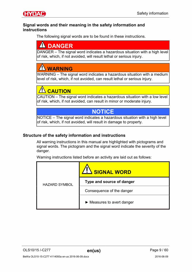
The following signal words are to be found in these instructions.
DANGER DANGER – The signal word indicates a hazardous situation with a high level of risk, which, if not avoided, will result lethal or serious injury.
WARNING WARNING – The signal word indicates a hazardous situation with a medium level of risk, which, if not avoided, can result lethal or serious injury.
CAUTION CAUTION – The signal word indicates a hazardous situation with a low level of risk, which, if not avoided, can result in minor or moderate injury.
NOTICE NOTICE – The signal word indicates a hazardous situation with a high level of risk, which, if not avoided, will result in damage to property.
Structure of the safety information and instructions All warning instructions in this manual are highlighted with pictograms and signal words. The pictogram and the signal word indicate the severity of the danger. Warning instructions listed before an activity are laid out as follows:
HAZARD SYMBOL
SIGNAL WORD
Type and source of danger
Consequence of the danger
► Measures to avert danger

Safety information
OLS10/15 /-C277 en(us) Page 10 / 60
BeWa OLS10-15-C277 4114093a en-us 2016-06-09.docx 2016-06-09
Proper/Designated Use Use the unit only for the application described in the following. The OffLine Separator OLS is a dewatering unit for hydraulic oils and gear lubrication oil with densities < 950 kg/m³. To drain, heat the operating fluid with a viscosity >100 mm/s2. Residual water contents of ≈ 100 ppm are possible.
NOTICE
Impermissible operating media.
The unit will be damaged.
► Use the unit only in conjunction with mineral oils for a water content < 15 filling volume %.
Proper or designated use of the product extends to the following:
• Observing all instructions contained in these operating instructions.
• Adhering to maintenance work.
Improper Use or Use Deviating from Intended Use Any use extending beyond this or deviating therefrom shall not be considered intended use. HYDAC Filter Systems GmbH will assume no liability for any damage resulting from such use. The user alone, shall assume any and all associated risk Improper use may result in hazards and/or will damage the unit. Examples of improper use:
• Operation with an impermissible fluid.
• Operation under non-approved operational conditions.
• Operation when the safety devices are defective.
• Modifications to the power unit made by the user or purchaser.
• Inadequate monitoring of parts that are subject to wear and tear
• Improperly performed repair work.

Safety information
OLS10/15 /-C277 en(us) Page 11 / 60
BeWa OLS10-15-C277 4114093a en-us 2016-06-09.docx 2016-06-09
Qualifications of personnel / target group Persons who work on the power unit must be aware of the associated hazards when using the power unit. Operating and specialist personnel must have read and understood the operating instructions, in particular the safety information and instructions, and applicable regulations before beginning work. The operating instructions and applicable regulations are to kept so they are accessible for operating and specialist personnel. These operating instructions is intended for: Auxiliary personnel: such persons have no specialized knowledge and perform work as instructed. Operating personnel: such persons have been instructed in power unit operation and are aware of potential hazards due to improper use. Specialist personnel: such persons have corresponding specialist training and several years' work experience. They are able to assess and perform the work assigned to them, they are also able to recognize potential hazards. Activity Person Knowledge
Transport / storage Auxiliary personnel
No specialist knowledge required
Startup operation Operations control
Operating Personnel
Product-specific knowledge Knowledge about how to handle operating media.
Troubleshooting, Maintenance, Decommissioning, Disassembly
Specialist personnel
Safe handling/use of tools Product-specific knowledge
Disposal Specialist personnel
Proper and environmentally-friendly disposal of materials and substances Decontamination of contaminants Knowledge about reuse

Unpacking the unit
OLS10/15 /-C277 en(us) Page 12 / 60
BeWa OLS10-15-C277 4114093a en-us 2016-06-09.docx 2016-06-09
Wear suitable clothing Loose-fitting clothing increases the risk of being caught or being drawn in on rotating parts, and the risk of getting caught on protruding parts. You can be severely injured or killed.
• Wear close-fitting clothing.
• Do not wear any rings, chains or any other jewelry.
• Wear work safety shoes.
• Wear gloves.
• Observe the information relating to personal protection equipment in the safety data sheet of the operating fluid.
Observe regulatory information Observe the following regulatory information and guidelines:
• Legal and local regulations for accident prevention
• Legal and local regulations for environmental protection
• Country-specific regulations, organization-specific regulations
Stoppage in an emergency (EMERGENCY STOP) In an emergency, switch the unit off at the main on/off switch or unplug the power connector.
Unpacking the unit
Prior to delivery, the unit is function and leak-tested in the factory. When unpacking the unit, check it for damage in transit.

Transporting the unit
OLS10/15 /-C277 en(us) Page 13 / 60
BeWa OLS10-15-C277 4114093a en-us 2016-06-09.docx 2016-06-09
Transporting the unit
Empty the unit completely before transport, including the coalescing and filter housings. Pull out the power plug and securely fasten the power cord to the unit.
Transporting with the crane Fasten suitable band loops to the base support for transporting with the crane.
Storing the unit
OLS10/15 /-C277 en(us) Page 14 / 60
BeWa OLS10-15-C277 4114093a en-us 2016-06-09.docx 2016-06-09
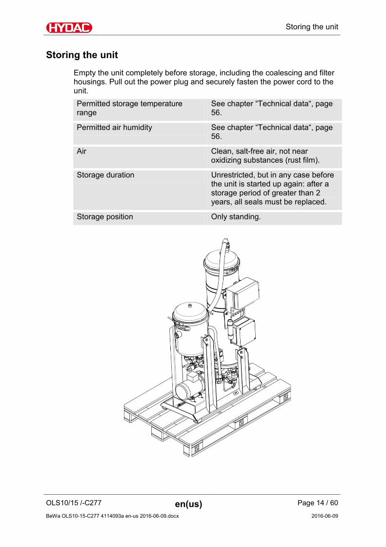
Storing the unit
Empty the unit completely before storage, including the coalescing and filter housings. Pull out the power plug and securely fasten the power cord to the unit. Permitted storage temperature range
See chapter “Technical data“, page 56.
Permitted air humidity See chapter “Technical data“, page 56.
Air Clean, salt-free air, not near oxidizing substances (rust film).
Storage duration Unrestricted, but in any case before the unit is started up again: after a storage period of greater than 2 years, all seals must be replaced.
Storage position Only standing.

Decoding the name plate
OLS10/15 /-C277 en(us) Page 15 / 60
BeWa OLS10-15-C277 4114093a en-us 2016-06-09.docx 2016-06-09
Decoding the name plate
Details for identifying the filtration unit can be found on the name plates on the unit and the components.
Item -> Description
(1) -> Name plate of filtration unit
(2) -> Name plate of electric motor
(3) -> Model code; for details, see page

Decoding the name plate
OLS10/15 /-C277 en(us) Page 16 / 60
BeWa OLS10-15-C277 4114093a en-us 2016-06-09.docx 2016-06-09
The following information can be found on the name plate of the unit: Row -> Description
Part No. -> Part number
S/N -> Serial number / year of production
Power -> Power consumption
Voltage/Grid -> Voltage / power supply
Frequency -> Frequency
Current -> Current consumption
Pressure max. -> Maximum permitted operating pressure
Pressure IN -> Permissible operating pressure at IN connection
Pressure OUT -> Permissible operating pressure at OUT connection
Weight -> Weight when empty
Flow rate -> Flow rate
Temp. oil -> Permitted fluid temperature range
Temp. amb. -> Permissible ambient temperature range
Volume -> Fluid volume in unit

Checking the scope of delivery
OLS10/15 /-C277 en(us) Page 17 / 60
BeWa OLS10-15-C277 4114093a en-us 2016-06-09.docx 2016-06-09
Checking the scope of delivery
The filtration unit comes factory-assembled. Check that the filtration unit is complete before starting up. The following items are supplied: Qty Description
1 OffLine separator
1 Operation and Maintenance Instructions (this document)

Characteristics of the unit
OLS10/15 /-C277 en(us) Page 18 / 60
BeWa OLS10-15-C277 4114093a en-us 2016-06-09.docx 2016-06-09
Characteristics of the unit
The OffLine Separator OLS is a dewatering unit for hydraulic oils and gear lubrication oil with densities below 950 kg/m3. The OLS is installed in the bypass flow; a pre-filter is available as an option.
Coalescing procedure The dewatering works according to the coalescence principle, during which water collects on the fibers of the coalescing element and is conveyed deeper into the coalescing element by the fluid flow. Smaller drops unite to form larger ones at the fiber nodes during this process. Larger drops settle downwards and can be drained off by opening a valve. The coalescing process is used mainly in systems in which small quantities of free water cause no damage, or in which fluids that exhibit good demulsifying properties (the capacity to give off water rapidly) are used. The application is used in the bypass flow. The use of a micro-filtration system is expedient to ensure the maximum possible service life of the coalescing elements.

Identifying components
OLS10/15 /-C277 en(us) Page 19 / 60
BeWa OLS10-15-C277 4114093a en-us 2016-06-09.docx 2016-06-09
Identifying components
Additional details regarding the versions can be found in the following.
Identifying components
OLS10/15 /-C277 en(us) Page 20 / 60
BeWa OLS10-15-C277 4114093a en-us 2016-06-09.docx 2016-06-09
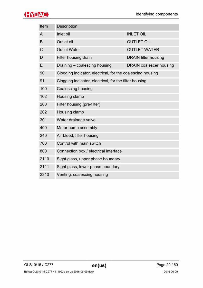
Item Description
A Inlet oil INLET OIL
B Outlet oil OUTLET OIL
C Outlet Water OUTLET WATER
D Filter housing drain DRAIN filter housing
E Draining – coalescing housing DRAIN coalescer housing
90 Clogging indicator, electrical, for the coalescing housing
91 Clogging indicator, electrical, for the filter housing
100 Coalescing housing
102 Housing clamp
200 Filter housing (pre-filter)
202 Housing clamp
301 Water drainage valve
400 Motor pump assembly
240 Air bleed, filter housing
700 Control with main switch
800 Connection box / electrical interface
2110 Sight glass, upper phase boundary
2111 Sight glass, lower phase boundary
2310 Venting, coalescing housing

Hydraulic diagram
OLS10/15 /-C277 en(us) Page 21 / 60
BeWa OLS10-15-C277 4114093a en-us 2016-06-09.docx 2016-06-09
Hydraulic diagram
The unit has the following hydraulic circuit:
Item Description
A Inlet oil INLET OIL
B Outlet oil OUTLET OIL
C Outlet Water OUTLET WATER
D Filter housing drain DRAIN filter housing
E Draining – coalescing housing DRAIN coalescer housing
90 Clogging indicator, electrical, for the coalescing housing
91 Clogging indicator, electrical, for the filter housing
100 Coalescing housing
200 Filter housing (pre-filter)
301 Water drainage valve
400 Motor pump assembly

Unit dimensions
OLS10/15 /-C277 en(us) Page 22 / 60
BeWa OLS10-15-C277 4114093a en-us 2016-06-09.docx 2016-06-09
Unit dimensions
The unit has the following dimensions: a = Required dismantling space for changing the coalescing elements
B = Recommended working range
All dimensions in mm.

Unit setup/connection
OLS10/15 /-C277 en(us) Page 23 / 60
BeWa OLS10-15-C277 4114093a en-us 2016-06-09.docx 2016-06-09
Unit setup/connection
NOTICE
Danger of tipping over / danger of slipping due to vibrations
The unit will be damaged
► Before starting it up, put the unit on a stable, horizontal surface.
Place the unit on a horizontal and level surface which is well ventilated. Install the suction port connection at the lowest part of the tank. This ensures that the water phase located at the base of the tank is reached. Install the return line as far as possible from the suction point in order to obtain an optimum intermixing of the tank contents. Take the following steps to prepare the unit for operation:
1. Check that the power supply cable is undamaged. Replace damaged cables immediately.
2. Check the connecting lines for leaks. Eliminate any leakages immediately.
3. Check and insert the filter element. For details, see page 41.
4. Check and insert the coalescing element. For details, see page 46.
5. The unit is ready for the next steps on the following pages.

Unit setup/connection
OLS10/15 /-C277 en(us) Page 24 / 60
BeWa OLS10-15-C277 4114093a en-us 2016-06-09.docx 2016-06-09
Notes on pipes/hosing Make sure that no vibrations or stresses are carried over to the filtration unit when connecting the piping. Make sure that no vibrations or stress/loading from other machinery and equipment are carried over to filtration unit. Make sure that no vibrations or stress/loading from other machinery and equipment are carried over to filtration unit. Use hoses or expansion joints if necessary. The pressure loss in a hydraulic line depends upon:
• flow rate
• kinematic viscosity
• Pipe dimensions
• Density of the fluid The pressure loss can be estimated for hydraulic oils as follows:
Δp ≈ 6.8 * L / d4 * Q * V * D Δp = Pressure differential in [bar]
L = Pipe length [m]
d = Internal pipe diameter [mm]
Q = Flow rate [l/min]
V = Kinematic viscosity [mm²/s]
D = Density [kg/dm³] Mineral oil-based hydraulic fluid has a density of ≈ 0.9 kg/dm³.
This applies to straight pipelines and hydraulic oils. Additional threaded connections and pipe bends increase the pressure differential. Keep the height difference between the pump and the oil level in the tank as low as possible. Constrictions in the connections and lines should be avoided. This could compromise suction output and cause cavitation . Take note that the nominal size of the connected hoses/piping must be at least as large as the inlet port sizes.

Unit setup/connection
OLS10/15 /-C277 en(us) Page 25 / 60
BeWa OLS10-15-C277 4114093a en-us 2016-06-09.docx 2016-06-09
Connecting the suction port (INLET) For the suction port connection, use a flexible hose that is resistant to negative pressure. Avoid constrictions in the connecting lines, as they compromise suction performance and increase the risk of cavitation.
NOTICE
Overpressure at the suction port connection
The unit will be damaged
► The pressure on the suction port connection IN must not be more than -0.4 to 4 bar.
Checking/setting the flow rate Set the maximum permissible volumetric flow for external motor-pump assembly. The maximum permissible flow rate can be found on the name plate. This is specified in the model code for the unit. (see the chapter “Model code”). The permitted tolerance is ± 10%, e.g.: Maximum permissible flow rate OLS 10/5 = 5 l/min ± 10% OLS 10/15 = 15 l/min ± 10%
Connecting the pressure connection (OUTLET) Make sure that the nominal width of the pressure line corresponds to the connector thread of the filter housing. Install the return line below the fluid level to prevent air from entering the fluid in the tank
If the clogging indicator pressure displayed for the a clean filter element is > 1 bar, use a differential pressure clogging indicator.
To prevent air from entering the medium, make sure that the pressure hose with lance is always below the oil level in operation.
Unit setup/connection
OLS10/15 /-C277 en(us) Page 26 / 60
BeWa OLS10-15-C277 4114093a en-us 2016-06-09.docx 2016-06-09
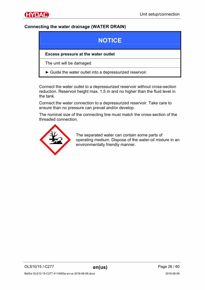
Connecting the water drainage (WATER DRAIN)
NOTICE
Excess pressure at the water outlet
The unit will be damaged
► Guide the water outlet into a depressurized reservoir.
Connect the water outlet to a depressurized reservoir without cross-section reduction. Reservoir height max. 1.5 m and no higher than the fluid level in the tank. Connect the water connection to a depressurized reservoir. Take care to ensure than no pressure can prevail and/or develop. The nominal size of the connecting line must match the cross-section of the threaded connection.
The separated water can contain some parts of operating medium. Dispose of the water-oil mixture in an environmentally friendly manner.

Unit setup/connection
OLS10/15 /-C277 en(us) Page 27 / 60
BeWa OLS10-15-C277 4114093a en-us 2016-06-09.docx 2016-06-09
Electrical connection of the unit The filtration unit has a connector cable with a power plug.
DANGER
Exposed electrical terminals in the terminal box on the electric motor
Danger of fatal injury due to electric shock
► Any work involving the electrical system may only be done by a properly trained, certified electrician.
Unwind the connector cable fully. Plug the power plug into a suitable, earthed, protected power outlet. Match the specifications for the power supply and frequency on the unit with the network specifications. The filtration unit has a thermal motor protection switch to protect it from electrical overload.
Checking the direction of rotation at the electric motor Start the motor by switching it on for a short time (jog mode). The arrow on the fan cover shows the correct direction of rotation. If the rotation is in the opposite direction, reverse it by means of the phase inverter in the connection plug.

Unit setup/connection
OLS10/15 /-C277 en(us) Page 28 / 60
BeWa OLS10-15-C277 4114093a en-us 2016-06-09.docx 2016-06-09
Connecting the remote control line The unit provides a connection for remote monitoring and a start/stop function. This lets you monitor, start and stop the unit from a control centre. Unscrew both screws to the cover (615) for connection. Remove the cover (615). The description of the connection clamps can be found on the rear.
NOTICE
Incorrect voltage / current at the relay contact
The control will be destroyed.
► Take note of the maximum voltage and current permitted in the relay contacts of 24 V DC / 2 A.
► Only use cables with a cable cross section of > 0.5 mm².
Use a free screw type conduit fitting on the lower side to connect the control line.

Unit setup/connection
OLS10/15 /-C277 en(us) Page 29 / 60
BeWa OLS10-15-C277 4114093a en-us 2016-06-09.docx 2016-06-09
Connect the pilot line and monitoring line to the X2 and X3 terminal according to the following description: Terminal: Pin
Function Description
X3:1-2 Output Device ACTIVE
Potential-free relay contact. It is closed when the motor pump assembly is running.
X3:3-4 Output Device OK
Potential-free relay contact. This is closed when there is no pending error. Can be used, for example, to issue an error notification when contact opens. Opens, for example if the voltage drops, the motor protection responds, the filter is clogged, the collecting pan is too full, etc.
X2:5-6 Output Reserve Potential-free relay contact. Has no function
X3:7-8 Input Input for potential-free push-button to switch motor-pump group on/off. No voltage is to be applied here.
X3:9-10 Input Reserve A voltage of 24V is to be applied here (opto-coupler input) to start a function. No function set yet.

Unit setup/connection
OLS10/15 /-C277 en(us) Page 30 / 60
BeWa OLS10-15-C277 4114093a en-us 2016-06-09.docx 2016-06-09
Connection box / connect interface (optional) This interface is located in the auxiliary box (800) with the designation +A2-A3. See circuit diagram with No. 4131413.
Connection terminals - Start/Stop external Pressing this push-button changes the current operating state. This means from operating state Stop -> Start and operating state Start becomes Stop. Terminal Line cross-section
X1:1 Potential-free push-button 0.5 … 2.5 mm²
X1:2 Potential-free push-button 0.5 … 2.5 mm²

Unit setup/connection
OLS10/15 /-C277 en(us) Page 31 / 60
BeWa OLS10-15-C277 4114093a en-us 2016-06-09.docx 2016-06-09
Connection terminals - Device active If the unit is in operation, the NO contact is closed. Terminal Voltage Current Line cross-section
X1:3 U = 24 V DC
0.5 A 0.5 … 2.5 mm²
X1:4 U = 24 V DC
0.5 A 0.5 … 2.5 mm²
Connection terminals - Device OK
If the unit is fault-free, the NO contact is closed. Terminal Voltage Current Line cross-section
X1:5 U = 24 V DC
0.5 A 0.5 … 2.5 mm²
X1:6 U = 24 V DC
0.5 A 0.5 … 2.5 mm²
Connection terminals – Clogging indicator VM1, prefilter clogged
Utilization category AC-15 in accordance with EN 60947 Terminal Voltage Current Line cross-section
X1:7 Base contact 230 V AC 3 A 0.5 … 2.5 mm²
X1:8 NC contact 230 V AC 3 A 0.5 … 2.5 mm²
X1:9 NO contact 230 V AC 3 A 0.5 … 2.5 mm² If the clogging indicator VM1 responds, the toggle switch switches. If the signal is present for longer than 60 seconds, the unit is switched off and the toggle switch returns to the starting position.
Connection terminals – Clogging indicator VM2, coalescing element clogged Utilization category AC-15 in accordance with EN 60947 Terminal Voltage Current Line cross-section
X1:10 Base contact 230 V AC 3 A 0.5 … 2.5 mm²
X1:11 NC contact 230 V AC 3 A 0.5 … 2.5 mm²
X1:12 NO contact 230 V AC 3 A 0.5 … 2.5 mm²

Unit setup/connection
OLS10/15 /-C277 en(us) Page 32 / 60
BeWa OLS10-15-C277 4114093a en-us 2016-06-09.docx 2016-06-09
If the clogging indicator VM2 responds, the toggle switch switches. If the signal is present for longer than 60 seconds, the unit is switched off and the toggle switch returns to the starting position.

Unit setup/connection
OLS10/15 /-C277 en(us) Page 33 / 60
BeWa OLS10-15-C277 4114093a en-us 2016-06-09.docx 2016-06-09
Remote control / Interval control Prioritization After switching on the unit, the set interval and the switch-on time will be started. Using the remote control, the motor-pump group can be switched on/off using the remote control. The timer with the interval and the switch-on time will continue to run in the background (remote control has priority). If the motor-pump group is switched off via the remote control, it starts automatically once the interval is over and runs time controlled via the timer. If the motor-pump group is switched on via the remote control, it stops once the interval is over. The timer has priority when switching off. Thus, the set interval and the switch-on time are not influenced by the remote control. Instead the timer assumes control again once the interval is over.

Operating / adjusting the control unit
OLS10/15 /-C277 en(us) Page 34 / 60
BeWa OLS10-15-C277 4114093a en-us 2016-06-09.docx 2016-06-09
Operating / adjusting the control unit
The unit has the following control unit and operating elements:
Item Description
610 Main switch See page 34 for details
611 Motor protection switch See page 37 for details
612 Interval control See page 36 for details
613 Status LEDs See page 35 for details
Switching the main switch on / off Switch the unit on or off at the main switch on the control unit. If the unit is switched off, all components up to the main switch are deenergized.

Operating / adjusting the control unit
OLS10/15 /-C277 en(us) Page 35 / 60
BeWa OLS10-15-C277 4114093a en-us 2016-06-09.docx 2016-06-09
Reading LED status The status LEDs with the symbols indicate operating status, service status and errors. The icons are explained below.
Icon An illuminated LED means the following: For details on remedies, see page:
Supply voltage is available 52
The unit is switched on 52
No malfunction / no error. 52
The motor protection switch has tripped. 52
The maximum differential pressure at the prefilter has been reached. 46
The maximum differential pressure at the coalescing elements has been reached. 46
Error message from water outlet. 52

Operating / adjusting the control unit
OLS10/15 /-C277 en(us) Page 36 / 60
BeWa OLS10-15-C277 4114093a en-us 2016-06-09.docx 2016-06-09
Adjusting the interval control Operating intervals and the operating duration are specified using the two interval control and time selector switches
The interval control and symbols indicate operating status, service status and errors. The icons are explained below. Icon Description
Permanent operation, time selector switch does not function.
One-time operation, time adjustment using time selector switch.
Once in 24 hours operation, time adjustment using time selector switch.
Once in 7 days operation, time adjustment using time selector switch.

Operating / adjusting the control unit
OLS10/15 /-C277 en(us) Page 37 / 60
BeWa OLS10-15-C277 4114093a en-us 2016-06-09.docx 2016-06-09
Adjusting the time selector switch The operating duration is set at the time selector switch. Icon Time setting
1 hour
2 hours
4 hours
8 hours
Checking the motor protection switch The motor protection switch is aligned and adjusted at the installed electric motor at the works. It is not necessary to correct the setting. If the motor protection switch triggers, proceed as indicated in the chapter "Status LED /" on page 52.
Switching unit on/off Switch the unit on at the main switch (610) and select the operating duration using interval control.
Automatic water drainage If the water sensor signals > 10 seconds, the drain level has been reached and the water drain value will be opened for approx. 12 seconds. This will result in approx. 3 liters of water draining out.

Starting up the unit
OLS10/15 /-C277 en(us) Page 38 / 60
BeWa OLS10-15-C277 4114093a en-us 2016-06-09.docx 2016-06-09
Starting up the unit
Before the unit is put into operation, it must first be connected hydraulically and electrically, as described in the above chapters. Note that the OLS unit contains no coalescing elements when it leaves the factory. If necessary, install the coalescing elements. Proceed as follows for commissioning:
1. Open the "INLET OIL" ball valve Close the "OUTLET OIL" ball valve.
2. Bleed the unit while filling.
3. Open the air-vent plug (x) on the prefilter.
4. Open the air-vent plug X1 on the coalescing
container.
5. Switch on the unit at the main switch.
6. If an external boost pump is present, switch
it on. Determine the flow rate present and adjust it in accordance with the permissible flow
Starting up the unit
OLS10/15 /-C277 en(us) Page 39 / 60
BeWa OLS10-15-C277 4114093a en-us 2016-06-09.docx 2016-06-09
rate (see type plate).
7. Observe the maximum primary pressure to the pump on the OLS.
8. Switch the pump on.
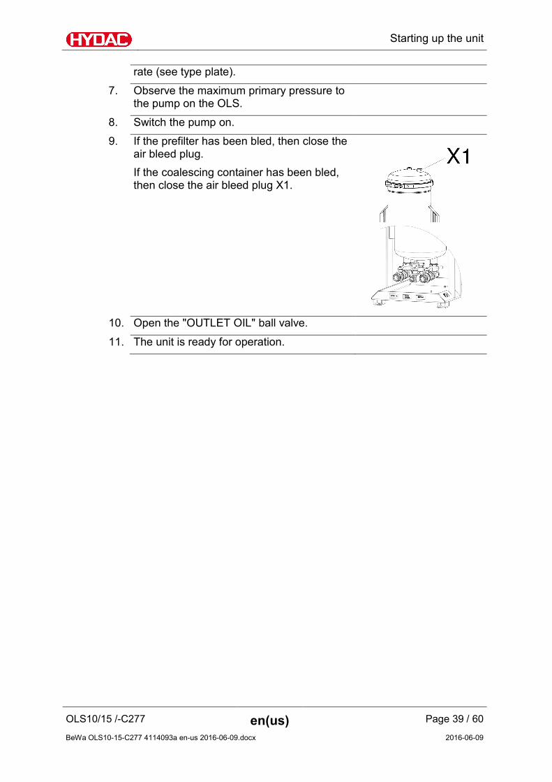
9. If the prefilter has been bled, then close the air bleed plug. If the coalescing container has been bled, then close the air bleed plug X1.
10. Open the "OUTLET OIL" ball valve.
11. The unit is ready for operation.

Performing maintenance
OLS10/15 /-C277 en(us) Page 40 / 60
BeWa OLS10-15-C277 4114093a en-us 2016-06-09.docx 2016-06-09
Performing maintenance
Perform all of the subsequent maintenance work regularly. Perform all of the subsequent maintenance work.
WARNING
Hot surfaces
Danger of burns
► Allow the unit to cool before any maintenance work.
Maintenance intervals Adhere to the following maintenance intervals.
For d
etai
ls, s
ee p
age
12 h
Dai
ly
Eve
ry 3
mon
ths
1 ye
ar
6 ye
ars
Whe
n in
dica
ted:
Perform visual check 40 - X - - - -
Replacing hydraulic hoses 41 - - - - X -
Replacing the filter element in the filter housing
41 - - - X - X
Changing the coalescing elements
46 - - - X - X
Perform visual check Check the unit for leaks, brittle hoses and cables daily. Replace damaged or brittle parts immediately.

Performing maintenance
OLS10/15 /-C277 en(us) Page 41 / 60
BeWa OLS10-15-C277 4114093a en-us 2016-06-09.docx 2016-06-09
Replacing hydraulic hoses Replace the hydraulic hoses every six years at the latest. The six operating years include two years storage duration for normal requirements in accordance with the rules of the Employers Liability Insurance Association BGR 237 for normal requirements.
Replacing the filter element in the filter housing To change the filter elements, proceed as follows:
1. Switch off the unit and make sure that it cannot be inadvertently switched back on.
2. Close all shut-off valves at the inlet and
outlet.
3. Unscrew the air bleed screw (x) completely using a 10 mm Allen wrench.
4. (1) Have a suitable drip tray on hand to
catch the operating fluid. (2) Open the drain fitting, and collect the escaping fluid in the tray. Once the housing has been completely drained, close the drain fitting.

Performing maintenance
OLS10/15 /-C277 en(us) Page 42 / 60
BeWa OLS10-15-C277 4114093a en-us 2016-06-09.docx 2016-06-09
5. Screw in the air bleed screw (x) by hand in a clockwise direction and tighten it firmly using a 10 mm AF Allen wrench.
6. Release the housing clamp and remove it.
Lift off the cover upwards.
7. Turn the element locking cap on the top filter
element by 90° in counterclockwise direction and lift off the locking cap.

Performing maintenance
OLS10/15 /-C277 en(us) Page 43 / 60
BeWa OLS10-15-C277 4114093a en-us 2016-06-09.docx 2016-06-09
8.
Dispose of the used filter elements in an environmentally friendly manner.
8. Clean the inside of the filter housing of
coarse dirt. Check the O-rings on the filter housing for damage. If necessary, replace them.
10. Insert the filter element into the bayonet
fitting (1), and lock the filter element by turning it 90° in the clockwise direction (2).

Performing maintenance
OLS10/15 /-C277 en(us) Page 44 / 60
BeWa OLS10-15-C277 4114093a en-us 2016-06-09.docx 2016-06-09
11. Place the element locking cap on the upper filter element (1). Turn the locking cap 90° in the clockwise direction to lock it in place.
No element locking cap = no filtration.
12. Place the cover at the top on the filter
housing. Mount the tensioning clamp and tighten it with a torque of 20 Nm. Secure using the lock nut.
We recommend applying lubricant containing a slip additive to the threads of the housing tensioning clamp each time filters are changed so that it remains easy to remove. Lubricant containing a slip additive – HYDAC p/no. 3066287
13. Open all shut-off valves at the inlet and outlet. If a pump is present, switch it on.
14. Fill the filter housing slowly. Slightly undo the air bleed screw (x). The air in the filter housing can escape via the slot on the air bleed screw. Bleed the filter housing through the air bleed screw (x) until operating fluid comes out. Tighten the air bleed screw.
15. The filter element change is now complete.

Performing maintenance
OLS10/15 /-C277 en(us) Page 45 / 60
BeWa OLS10-15-C277 4114093a en-us 2016-06-09.docx 2016-06-09
Performing maintenance
OLS10/15 /-C277 en(us) Page 46 / 60
BeWa OLS10-15-C277 4114093a en-us 2016-06-09.docx 2016-06-09
Changing the coalescing elements To replace the coalescing elements, proceed as follows:
1. Switch off the unit at the main switch.
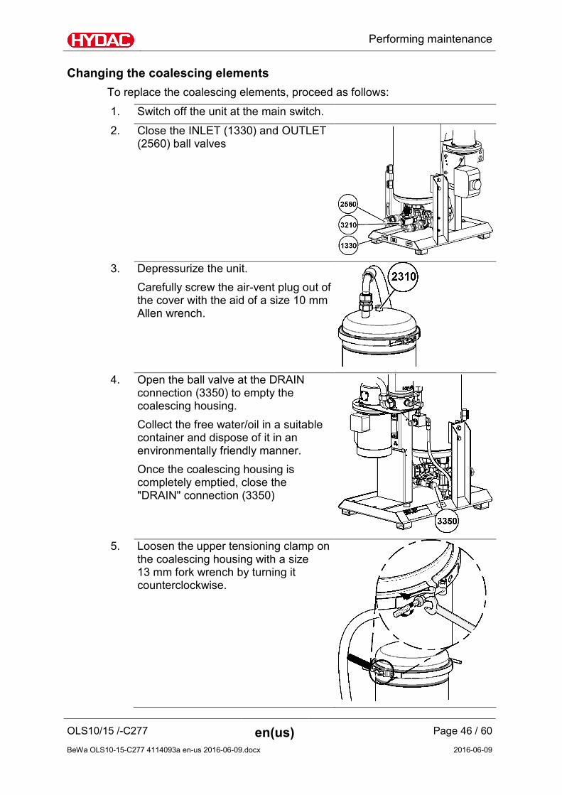
2. Close the INLET (1330) and OUTLET (2560) ball valves
3. Depressurize the unit.
Carefully screw the air-vent plug out of the cover with the aid of a size 10 mm Allen wrench.
4. Open the ball valve at the DRAIN
connection (3350) to empty the coalescing housing. Collect the free water/oil in a suitable container and dispose of it in an environmentally friendly manner. Once the coalescing housing is completely emptied, close the "DRAIN" connection (3350)
5. Loosen the upper tensioning clamp on
the coalescing housing with a size 13 mm fork wrench by turning it counterclockwise.

Performing maintenance
OLS10/15 /-C277 en(us) Page 47 / 60
BeWa OLS10-15-C277 4114093a en-us 2016-06-09.docx 2016-06-09
6. 1 - Remove the housing clamp (2400). 2 - Remove the cover by lifting it upward and set it down to the side.
7. Remove the element set from the
coalescing housing. Use both handles to accomplish this.
8. Rotate the element set on the head by
180°.
Performing maintenance
OLS10/15 /-C277 en(us) Page 48 / 60
BeWa OLS10-15-C277 4114093a en-us 2016-06-09.docx 2016-06-09
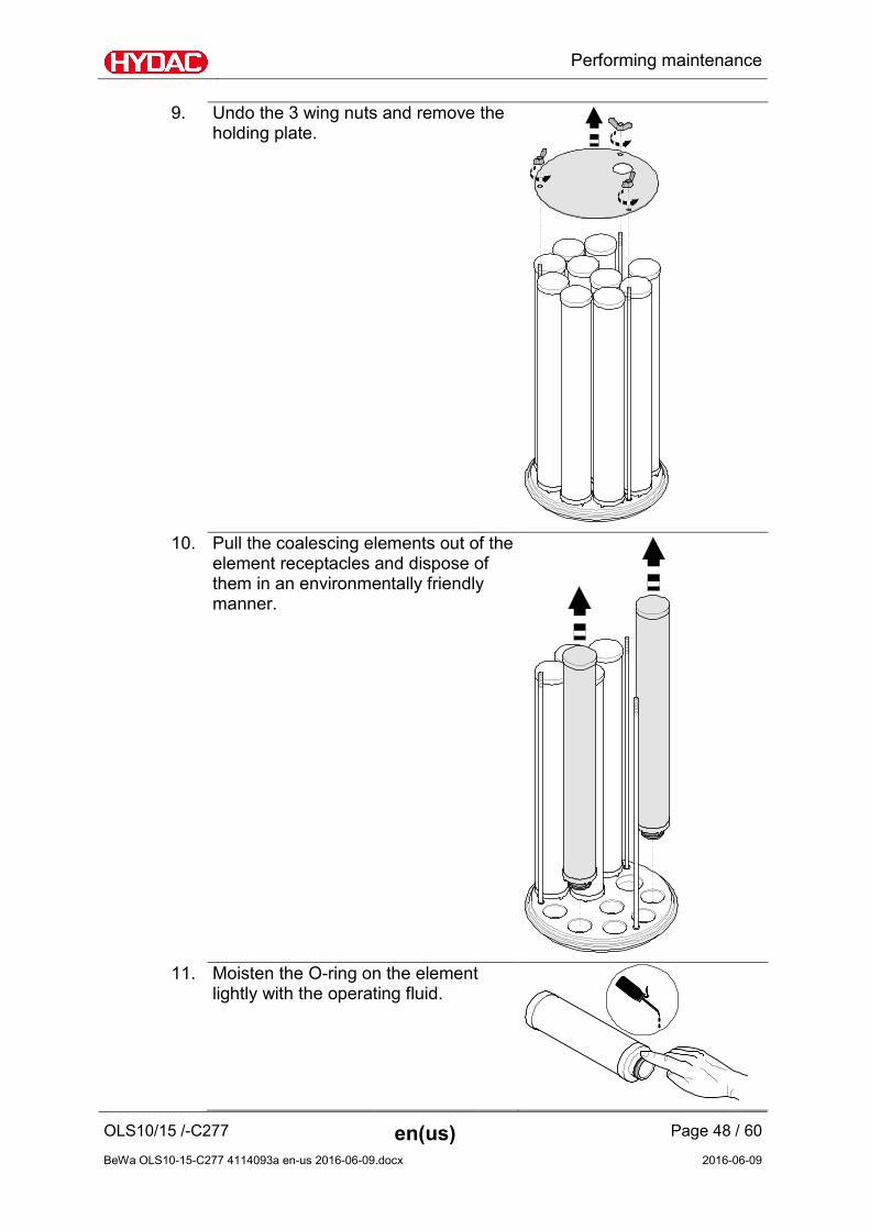
9. Undo the 3 wing nuts and remove the holding plate.
10. Pull the coalescing elements out of the
element receptacles and dispose of them in an environmentally friendly manner.
11. Moisten the O-ring on the element
lightly with the operating fluid.
Performing maintenance
OLS10/15 /-C277 en(us) Page 49 / 60
BeWa OLS10-15-C277 4114093a en-us 2016-06-09.docx 2016-06-09
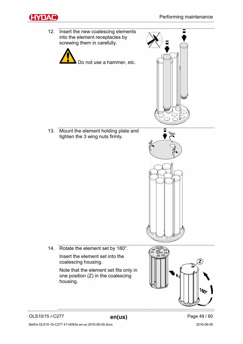
12. Insert the new coalescing elements into the element receptacles by screwing them in carefully.
Do not use a hammer, etc.
13. Mount the element holding plate and
tighten the 3 wing nuts firmly.
14. Rotate the element set by 180°.
Insert the element set into the coalescing housing. Note that the element set fits only in one position (Z) in the coalescing housing.

Performing maintenance
OLS10/15 /-C277 en(us) Page 50 / 60
BeWa OLS10-15-C277 4114093a en-us 2016-06-09.docx 2016-06-09
15. Clean the sealing surface on the cover. Check the O-ring for damage. Replace it if necessary.
16. 1 - Place the cover on the coalescing housing. 2 - Place the housing clamp over the coalescing housing.
17. Use an SW 13 fork wrench to tighten
the tensioning clamps evenly to a maximum of 20 Nm. Screw open the lock nut and secure the connection.
18. Open the ball valves INLET (1330)
and OUTLET (2560).

Performing maintenance
OLS10/15 /-C277 en(us) Page 51 / 60
BeWa OLS10-15-C277 4114093a en-us 2016-06-09.docx 2016-06-09
19. Bleed the filtration unit.
20. Bleed the coalescing housing through
the air-vent plug (2310) at the cover.
21. The replacement of the coalescing
element is completed.

Status LED / Causes and remedies
OLS10/15 /-C277 en(us) Page 52 / 60
BeWa OLS10-15-C277 4114093a en-us 2016-06-09.docx 2016-06-09
Status LED / Causes and remedies
The status LEDs only indicate to you the status or an error of the unit in Standard / Premium control type. The following errors could have different causes. The following provides information on which remedial measures are required. To reset the error message on the control, switch off the unit at the main switch for at least three seconds.
Status LED Cause(s) Remedy
LED is dark = LED is off
No power supply. Check the feed-line and plug.
LED flashing
The main switch is switched off but the power supply is on
Check the main switch.
The main switch is switched on, during operation there was a drop in voltage => restart protection.
Switch off the unit at the main switch for 3 seconds.
LED lights up
LED flashing
LED flashing
The main switch is on, but the unit is not running.
Contact HYDAC.
Electric motor / pump is not running
Interval control is active.
Check the interval settings.

Status LED / Causes and remedies
OLS10/15 /-C277 en(us) Page 53 / 60
BeWa OLS10-15-C277 4114093a en-us 2016-06-09.docx 2016-06-09
Status LED Cause(s) Remedy
The is no power at the electric motor.
The power outlet used is free of voltage. The mains connector is not plugged in. Plug in the power plug. Inspect the unit supply line for damage. If the unit supply line is defective, replace it immediately.
The mains voltage or frequency do not correspond to the specifications on the unit.
Use a unit that is suitable for the mains voltage.
The unit is switched off at the main switch.
Switch on the unit at the main switch.
No flow
The suction hose is kinked or faulty or a shut-off device is closed.
Check the suction hose for freedom of passage. Replace it if necessary.
There is air in the suction line and the pump.
Fill the pump via the suction hose / hose coupling.
The viscosity of the fluid is too high.
Check the viscosity of the fluid. Heat the fluid to achieve the permissible viscosity.
The is no power to the electric motor.
Check the supply line to the filtration unit. Replace it if necessary.
The electric motor / pump is defective.
Contact HYDAC.
The transport seals were not removed.
Remove the transport seals. The transport seals are the yellow plastic bungs.
The pressure loss in the suction line is too great.
Ensure that the pressure at the inlet is within the permitted range.

Status LED / Causes and remedies
OLS10/15 /-C277 en(us) Page 54 / 60
BeWa OLS10-15-C277 4114093a en-us 2016-06-09.docx 2016-06-09
Status LED Cause(s) Remedy
The suction hose is not suitable for negative pressure.
Use a hose that is resistant to negative pressure.
The prefilter element is clogged.
The coalescing elements are clogged. (The clogging indicator is responding)
If the maximum differential pressure in the filter housing or coalescing housing has been reached, the control will automatically switch off the unit. Once a clogging indicator responds, the unit will be switched off with a time delay of 60 seconds.
Replace the filter element or coalescing element depending on which status LED is lit.
The viscosity of the fluid is too high.
Check the viscosity of the fluid. Heat the fluid to achieve the permissible viscosity.
The suction line at the inlet is generating too much loss of pressure.
Ensure that the pressure at the inlet is within the permitted range.
Water drainage error The phase limit sensor is defective or the water drainage valve does not open.
Contact HYDAC.

Customer Service / Service
OLS10/15 /-C277 en(us) Page 55 / 60
BeWa OLS10-15-C277 4114093a en-us 2016-06-09.docx 2016-06-09
Customer Service / Service
Regular inspection and maintenance work are indispensable to ensure trouble-free operation and a long service life for your unit. HYDAC SERVICE GMBH Friedrichsthaler Str. 15A, Werk 13 66540 Neunkirchen-Heinitz Germany Telephone: +49 6897 509 883 Fax: +49 6897 509 324 E-mail: [email protected]
Taking the unit out of operation
Drain the unit completely, including all of its components, before decommissioning. Pull out the power plug and securely fasten the hoses and power cord to the unit.
Shutting down the unit
See chapter "Taking the unit out of operation".
Disposing of the unit
Dispose of the packaging material in an environmentally friendly manner. After dismantling the unit and separating the various materials, dispose of the unit in an environmentally friendly manner.
Spare parts list
Qty Part no. Description 1 * Motor/pump assembly 10 3277940 Coalescing element, 5 µm N20WR005-1F 2 6005449 O-ring 270x10 (NBR) 1 1251590 Prefilter element, 2 µm N15DM002
*) Upon request

Technical data
OLS10/15 /-C277 en(us) Page 56 / 60
BeWa OLS10-15-C277 4114093a en-us 2016-06-09.docx 2016-06-09
Technical data
Hydraulic data flow rate 15 l/min Permitted viscosity range 15 … 100 mm/s² Permissible fluids Mineral oil to DIN 50524
Gear lubrication oil to DIN 51517, 51524
Permitted maximum fluid temperature 80°C Operating pressure (setting at pressure relief valve) 6 bar Permitted pressure at inlet (INLET OIL) -0.4 … 4 bar Permissible pressure at the water drain Depressurized Housing material Stainless steel: 1.4301 Material of sealings NBR INLET connector G1" OUTLET connector G1" Connection for water drain G 1/2 " Electrical data Power supply See type label Power consumption See type label Required fuse element 16 Amperes Power cable, length 0.5 m Protection class to DIN 40050 IP 54 General data Permissible ambient temperature range 0 to 45°C Permitted storage temperature range 0 to 45°C Permitted relative humidity during storage ≤ 60 % Weight when empty ≈ 140 kg

Model code
OLS10/15 /-C277 en(us) Page 57 / 60
BeWa OLS10-15-C277 4114093a en-us 2016-06-09.docx 2016-06-09
Model code
OLS 10 / 15 - S - N - 20 - 1 - BM - z - z - z / V
Type OLS Filter Size 10 = Number of coalescing elements Nominal flow rate 15 = 15 l/min Pump version z = without pump G = Gear pump GD = Gear pump for diesel fuel S = Vane pump Power supply B = P = 480 V, 3 Ph C = P = 380 V, 3 Ph G = P = 440 V, 3 Ph L = P = 115 V, 3 Ph M = 230 V, 1 Ph* N = P = 400 V, 3 Ph O = P = 460 V, 3 Ph P = P = 575 V, 3 Ph S = P = 500 V, 3 Ph R = P = 415 V, 3 Ph W = 230 V, 3 Ph* X = Other voltage (on request) z = Without electro motor L60, M60 = Operation at 60 Hz * = Standard in Europe according to CENELEC
HD472 S1 at 50Hz
Element length 20 = Coalescing element 20“ – N20WRxxx Prefilter 2 = OLF 15-60 z = without Clogging indicator BM = Differential pressure indicator, visual (VMxBM.1) C = Differential pressure indicator, electrical (VMxC.0) z = Without E = Back-pressure indication VMF 0.6KO Heater 1 = 1 kW 2 = 2 kW z = Without Water drain 1 = Automatic z = Manual Instrumentation z = without Additional details PKZ = On-off switch with motor protection switch FA2 = On/Off switch with motor protection switch and switch-off when filter is
clogged. Requires no neutral conductor, all voltages, clogging indicator C required.
V = Seals made of Viton (FPM)

Index
OLS10/15 /-C277 en(us) Page 58 / 60
BeWa OLS10-15-C277 4114093a en-us 2016-06-09.docx 2016-06-09
Index
A accident prevention ...................................................... 12 ambient temperature .............................................. 16, 56 Auxiliary personnel ........................................................ 11
B Back-pressure ................................................................ 57
C care........................................................................ 2, 5, 26 Cause ............................................................................. 52 Clogging indicator ........................................ 20, 21, 31, 57 collecting pan ................................................................ 29 connecting ................................................... 23, 24, 25, 26 Connection .................................................. 20, 30, 31, 56 Content ........................................................................... 3 Control .......................................................................... 20
D Density .......................................................................... 24 Description ..................... 15, 16, 17, 20, 21, 29, 34, 36, 55 dewatering .............................................................. 10, 18 Differential pressure ..................................................... 57 Differential pressure indicator ...................................... 57 DIN ................................................................................ 56 Disposal ......................................................................... 11 Documentation Representative ...................................... 2 DRAIN .......................................................... 20, 21, 26, 46 draining ......................................................................... 37
E Electrical data ................................................................ 56 Error .............................................................................. 35 Error message ............................................................... 35
F filling ........................................................................ 10, 38 Filter ............................................................ 10, 20, 21, 57 Filter housing ........................................................... 20, 21 filtration ............................... 15, 17, 18, 24, 27, 44, 51, 53 Flow rate ................................................................. 16, 24
G gear ......................................................................... 10, 18 Gear pump .................................................................... 57
H Hazard symbol ............................................................. 7, 9 Heater ........................................................................... 57 Hydraulic data ............................................................... 56
Hydraulic diagram ......................................................... 21
I Imprint ............................................................................ 2 IN 16, 25 Inlet ......................................................................... 20, 21 INLET .......................................... 20, 21, 25, 38, 46, 50, 56 Internal pipe diameter .................................................. 24 IP 56
M Main switch ................................................................... 34 Maintenance .................................................. 1, 11, 17, 40 Maintenance interval .................................................... 40 Maintenance intervals .................................................. 40 Material of sealings ....................................................... 56 Measures ........................................................................ 9 Mineral oil ............................................................... 24, 56 Model code ........................................................15, 25, 57 Motor protection switch ............................................... 34 Motor pump assembly ............................................ 20, 21
O Off switch ...................................................................... 57 operating 5, 6, 7, 10, 11, 12, 16, 26, 30, 34, 35, 36, 37, 41,
44, 48 Operation ...........................................................10, 17, 57 Operations control ........................................................ 11 OUT ............................................................................... 16 Outlet ...................................................................... 20, 21 OUTLET................................. 20, 21, 25, 38, 39, 46, 50, 56
P Power consumption ................................................ 16, 56 Pressure differential...................................................... 24 Proper/Designated Use ................................................. 10 Protection class ............................................................. 56 Publisher ......................................................................... 2 Pump ............................................................................. 57
R Remedy ......................................................................... 52 replacement .................................................................. 51 Residual water content ................................................. 10
S select ......................................................................... 6, 37 Service ........................................................................... 55 setting ................................................................25, 37, 56 Signal word ..................................................................... 9 signal words .................................................................... 9 Size ................................................................................ 57

Index
OLS10/15 /-C277 en(us) Page 59 / 60
BeWa OLS10-15-C277 4114093a en-us 2016-06-09.docx 2016-06-09
Spare part ...................................................................... 55 Spare parts .................................................................... 55 Spare parts list ............................................................... 55 Specialist personnel ...................................................... 11 Supply voltage ............................................................... 35 switching off .................................................................. 33 switching on .................................................................. 33
T Time .............................................................................. 37 Transport ....................................................................... 11
transporting .................................................................. 13 Troubleshooting ............................................................ 11
V Vane pump .................................................................... 57
W Weight .................................................................... 16, 56

HYDAC FILTER SYSTEMS GMBH Industriegebiet Postfach 1251 66280 Sulzbach/Saar 66273 Sulzbach/Saar Germany Germany Phone: +49 (0) 6897 509 01 Central Fax: +49 (0) 6897 509 9046 (Technical Department) Fax: +49 (0) 6897 509 577 (Sales Department) Internet: www.hydac.com E-mail: [email protected]