om, gardena, sileno city, smart sileno city, sileno life
TRANSCRIPT

gardena.com
Operator‘s manualSILENO city, smart SILENO citySILENO life, smart SILENO life
InDesign P01 omslag P01_P02_a5.indd 1InDesign P01 omslag P01_P02_a5.indd 1

Contents
1 Introduction1.1 Introduction........................................................... 31.2 Product overview...................................................41.3 Symbols on the product........................................ 51.4 Symbols on the display......................................... 51.5 Symbols on the battery......................................... 51.6 General manual instructions................................. 61.7 Menu structure overview 1.................................... 71.8 Menu structure overview 2.................................... 81.9 Display.................................................................. 91.10 Keypad ............................................................... 9
2 Safety2.1 Safety information............................................... 102.2 Safety definitions.................................................112.3 Safety instructions for operation..........................11
3 Installation3.1 Introduction - Installation..................................... 143.2 Main components for installation.........................143.3 General preparations.......................................... 143.4 Before the installation of the wires...................... 143.5 Installation of the product.................................... 193.6 To put the wire into position with stakes............. 213.7 To bury the boundary wire or the guide wire.......213.8 To extend the boundary wire or the guide wire... 213.9 After the installation of the product......................223.10 To do the product settings.................................22
4 Operation4.1 The ON/OFF button............................................ 304.2 To start the product............................................. 304.3 Operating modes.................................................304.4 To stop the product............................................. 314.5 To switch off the product..................................... 314.6 To charge the battery.......................................... 314.7 Adjust the cutting height......................................32
5 Maintenance5.1 Introduction - maintenance..................................335.2 Clean the product................................................335.3 Replace the blades............................................. 345.4 Firmware update................................................. 345.5 Battery.................................................................355.6 Winter service..................................................... 35
6 Troubleshooting6.1 Introduction - troubleshooting..............................37
6.2 Fault messages...................................................376.3 Information messages.........................................426.4 Indicator lamp in the charging station................. 436.5 Symptoms........................................................... 446.6 Find breaks in the loop wire................................ 45
7 Transportation, storage and disposal7.1 Transportation..................................................... 487.2 Storage................................................................487.3 Disposal.............................................................. 48
8 Technical data8.1 Technical data.....................................................49
9 Warranty9.1 Warranty terms....................................................52
10 EC Declaration of Conformity10.1 EC Declaration of Conformity............................53
2 1298 - 010 -

1 Introduction
1.1 IntroductionSerial number:
PIN code:
Product registration key:
The serial number is on the product carton and on the product rating plate. Refer to Product overview on page 4.• Use the serial number to register your product on www.gardena.com.
1.1.1 SupportFor support about the GARDENA product, speak to yourGARDENA service.
1.1.2 Product description
Note: GARDENA regularly updates the appearanceand function of the products. Refer to Support on page3.
The product is a robotic lawn mower. The product has abattery power source and cuts the grass automatically. Itcontinuously alternates between mowing and charging.The movement pattern is random, which means that thelawn is mowed evenly and with less wear. The boundarywire and the guide wire controls the movement of theproduct within the work area. Sensors in the productsenses when it is approaching the boundary wire. Thefront of the product always passes the boundary wire bya specific distance before the product turns around.When the product hits an obstacle or approaches theboundary wire the product selects a new direction.
The operator selects the operation settings with the keyson the keypad. The display shows the selected andpossible operation settings, and the operation mode ofthe product.
1.1.2.1 Mowing techniqueThe product is emission free, easy to use and savesenergy. The frequent cutting technique improves thegrass quality and decreases the use of fertilizers.Collection of grass is not necessary.
1.1.2.2 Find the charging stationThe product operates until the battery state of charge islow. Then it follows the guide wire to the chargingstation. The guide wire is laid from the charging stationtowards, for instance, a remote part of the work area orthrough a narrow passage. The guide wire is connectedwith the boundary wire and makes it much easier andfaster for the product to find the charging station.
1298 - 010 - Introduction - 3

1.2 Product overview
1
5
4
3
9
28
21
27
10
22 23
29
26
3025
24
19
68
72
18
15
14
17
16
20
13
1211
The numbers in the figure represent:
1. Body2. Hatch to display and keypad3. Stop button4. Rear wheel (SILENO city) / Rear wheels (SILENO
life)5. Front wheels6. Charging station7. Contact plates8. LED for operation check of the charging station,
boundary wire and guide wire9. Cutting height adjustment10. Rating plate11. Display12. Keypad
13. ON/OFF button14. Cutting system15. Blade disc16. Handle17. Chassis box with electronics, battery and motors18. Battery cover19. Power supply 120. Loop wire for boundary loop and guide wire21. Couplers for loop wire22. Stakes23. Connector for the loop wire24. Screws for securing the charging station25. Measurement gauge for help when installing the
boundary wire (the measurement gauge is brokenloose from the box)
1 The appearance may differ depending on market.
4 - Introduction 1298 - 010 -

26. smart gateway power supply (only for smart model)27. Low voltage cable28. smart gateway (only for smart model)29. smart gateway LAN-cable (only for smart model)30. Operator’s Manual and Quick Guide
1.3 Symbols on the productThese symbols can be found on the product. Study themcarefully.
WARNING: Read the user in-structions before operatingthe product.
WARNING: Disable the prod-uct before working on or lift-ing the product.
WARNING: Keep a safe dis-tance from the product whenoperating. Keep your handsand feet away from the rotat-ing blades.
WARNING: Do not ride onthe product. Do not put yourhands or feet close to or un-der the product.
Use a detachable power sup-ply as defined on the ratingplate next to the symbol.
This product conforms to theapplicable EC Directives.
It is not permitted to dispose this productas normal household waste. Ensure thatthe product is recycled in accordance withlocal legal requirements.
The low-voltage cable must not beshortened, extended or spliced.
Do not use a trimmer nearby the low-voltage cable. Be careful when trimmingedges where the cables are placed.
1.4 Symbols on the display
The schedule menu is used to set whenthe product cuts the lawn.
The SensorControl function automaticallyadapts the cutting intervals to the grassgrowth.
The settings menu is used to set thegeneral product settings.
Only for smart SILENO city and smartSILENO life.
The GARDENA smart system enableswireless interaction between your smartproduct and the GARDENA smart system.
The product will not cut the grass due tothe schedule function.
The product overrides the schedulefunction.
The battery indicator shows the batterystate of charge. When the productcharges the symbol flashes.
The product is in the charging station butdo not charge the battery.
The product is set in ECO-mode.
1.5 Symbols on the battery
Read the user instructions.
Do not discard the battery into fire and donot expose the battery to a heat source.
1298 - 010 - Introduction - 5
Do not immerse the battery into water.
1.6 General manual instructionsThe following system is used in the Operator’s Manualto make it easier to use:
• Text written in italics is a text that is shown in thedisplay or is a reference to another section in theOperator’s Manual.
• Text written in bold is one of the buttons on theproduct.
• Text written in UPPERCASE and italics refer to thedifferent operating modes available in the product.
6 - Introduction 1298 - 010 -

1.7 Menu structure overview 1
Schedule
Overview week
Period 1 Period 2 Copy
Su Current
day
All weekSaFrThWeTuMoAll
days
Reset
* smart SILENO city and smart SILENO life
Wizard Advanced
smart system*
Good Poor Bad
Connected
Yes/No
Signal
strength
StatusExcludedevice
SensorControl
Low/Mid/High
Cutting timeUseSensorControl
1298 - 010 - Introduction - 7

1.8 Menu structure overview 2
Settings
Time &
date
Set time Set date Time format Date format
Language Country Reset all
user settings
About
Security Lawn coverage Installation General
Low Medium*
Change
PIN code
New loop
signal
Security level Advanced
Area 1-3
How? How
often?
How
far?
Disable
ResetTest
More
Starting
pointDrive past
wire
ECO
modeMower
house
High
* SILENO life, smart SILENO life
Frost
sensor
Unit
format
CorridorCut
8 - Introduction 1298 - 010 -

1.9 DisplayThe display on the product shows information andsettings of the product.
To access the display, push the STOP button and openthe hatch.
1.10 Keypad The keypad on the product lets the operator navigate inthe menu. To access the keypad, push the STOP buttonand open the hatch.
• Use the ON/OFF button (A) to switch on andswitch off the product. The indicator lamp on thekeypad is an important status indicator. Refer to The indicator lamp on page 30.
• Use the Start button (B) to start the operation ofthe product.
• Use the Menu button (C) to go to the main menu.
Note: The Menu button is also used as a Backbutton to move up in the menu lists.
• Use the Mode button (D) to select operating mode.• Use the OK button (E) to confirm the settings you
select in the menus.• Use arrow buttons (F) to navigate in the menu. Use
the up/down arrow buttons to enter PIN code, timeand date.
A
B
DC
E
F
1298 - 010 - Introduction - 9

2 Safety2.1 Safety information
2.1.1 IMPORTANT. READ CAREFULLYBEFORE USE. KEEP FOR FUTUREREFERENCEThe operator is responsible for accidents or hazards occurring toother people or property.This appliance is not intended for use by persons (includingchildren) with reduced physical, sensory or mental capabilities (thatcould affect a safe handling of the product), or lack of experienceand knowledge, unless they have been given supervision orinstruction concerning use of the appliance by a personresponsible for their safety.This appliance can be used by children aged from 8 years andabove and persons with reduced physical, sensory or mentalcapabilities or lack of experience and knowledge if they have beengiven supervision or instruction concerning use of the appliance ina safe way and understand the hazards involved. Local regulationsmay restrict the age of the operator. Cleaning and maintenanceshall not be made by children without supervision.Never connect the power supply to an outlet if the plug or cord isdamaged. Worn or damaged cord increase the risk of electricshock.Only charge the battery in the included charging station. Incorrectuse may result in electric shock, overheating or leaking ofcorrosive liquid from the battery. In the event of leakage ofelectrolyte, flush with water/neutralizing agent. Seek medical help ifit comes in contact with the eyes.Use only original batteries recommended by the manufacturer.Product safety cannot be guaranteed with other than originalbatteries. Do not use non-rechargeable batteries.
10 - Safety 1298 - 010 -

The appliance must be disconnected from the supply mains whenremoving the battery.
WARNING: The productcan be dangerous if usedincorrectly.
WARNING: Do not usethe product whenpersons, especiallychildren, or animals arein the work area.
WARNING: Keep yourhands and feet awayfrom the rotating blades.Never put your hands orfeet close to or under theproduct when it isswitched on.
WARNING: In the eventof an injury or accidentseek medical help.
2.2 Safety definitionsWarnings, cautions and notes are used to point outspecially important parts of the manual.
WARNING: Used if there is a risk ofinjury or death for the operator or bystandersif the instructions in the manual are notobeyed.
CAUTION: Used if there is a risk ofdamage to the product, other materials orthe adjacent area if the instructions in themanual are not obeyed.
Note: Used to give more information that is necessaryin a given situation.
2.3 Safety instructions for operation2.3.1 Use• The product may only be used with the equipment
recommended by the manufacturer. All other typesof use are incorrect. The manufacturer’sinstructions with regard to operation/maintenancemust be followed precisely.
• Warning signs shall be placed around the workarea of the product if it is used in public areas. Thesigns shall have the following text: Warning!Automatic lawnmower! Keep away from themachine! Supervise children!
Warning!Automatic lawnmower!
Keep away from the machine!Supervise children!
Warning!
Automatic lawnmower!
Keep away from the machine!
Supervise children!
• Use the park mode, refer to Park on page 31 orswitch off the product when persons, especiallychildren, or animals are in the work area. It isrecommended to program the product for useduring hours when the area is free from activity.Refer to To set the schedule on page 23.Consider that certain animals, e.g. hedgehogs, areactive at night. They can potentially be harmed bythe product.
• Do not install the charging station, including anyaccessory, at a location that is below, or within 60cm / 24 in. from, any combustible material. Do notinstall the power supply unit in easily flammablesurroundings. In case of malfunction, heating ofthe charging station and the power supply mayoccur and create a potential risk of fire.
1298 - 010 - Safety - 11

• The product may only be operated, maintained andrepaired by persons that are fully conversant withits special characteristics and safety regulations.Please read the Operator’s Manual carefully andmake sure you understand the instructions beforeusing the product.
• It is not permitted to modify the original design ofthe product. All modifications are made at yourown risk.
• Check that there are no foreign objects such asstones, branches, tools or toys on the lawn. If theblades hit foreign objects the blades can bedamaged. Always switch off the product with theON/OFF button before clearing a blockage. Inspectthe product for damage before staring the productagain.
• If the product starts to vibrate abnormally. Alwaysswitch off the product with the ON/OFF button andinspect for damage before staring the productagain.
• Start the product according to the instructions.When the product is switched on, make sure tokeep your hands and feet away from the rotatingblades. Never put your hands and feet under theproduct.
• Never touch moving hazardous parts, such as theblade disc, before it has come to a complete stop.
• Never lift up the product or carry it around when itis switched on.
• Do not let persons who do not know how theproduct works and behaves use it.
• The product must never be allowed to collide withpersons or other living creatures. If a person orother living creature comes in the product’s way itshall be stopped immediately. Refer to To stop theproduct on page 31.
• Do not put anything on top of the product or itscharging station.
• Do not allow the product to be used with adefective guard, blade disc or body. Neither shouldit be used with defective blades, screws, nuts orcables. Never connect a damaged cable, or toucha damaged cable before it is disconnected fromthe supply.
• Do not use the product if the ON/OFF button andSTOP button does not work.
• Always switch off the product using the ON/OFFbutton when the product is not in use. The productcan only start when the product has been switchedon with the ON/OFF button and the correct PINcode has been entered.
• GARDENA does not guarantee full compatibilitybetween the product and other types of wirelesssystems such as remote controls, radiotransmitters, hearing loops, underground electricanimal fencing or similar.
• Metal objects in the ground (for example reinforcedconcrete or anti-mole nets) can result in astoppage. The metal objects can causeinterference with the loop signal which then canlead to a stoppage.
• Operation and storage temperature range is 0-50°C / 32-122 °F. Temperature range for charging is0-45 °C / 32-113 °F. Too high temperatures mightcause damage to the product.
2.3.2 Battery safety
WARNING: Lithium-ion batteries canexplode or cause fire if disassembled, short-circuited, exposed to water, fire, or hightemperatures. Handle carefully, do notdismantle, open the battery or use any typeof electrical/mechanical abuse. Avoidstorage in direct sunlight.
For more information about the battery, refer to Batteryon page 35
2.3.3 How to lift and move the product
WARNING: The product must beswitched off before lifting it. The product isdisabled when the indicator lamp on thekeypad is not lit.
CAUTION: Do not lift the product whenit is parked in the charging station. It candamage the charging station and/or theproduct. Push STOP and pull the productout of the charging station before lifting it.
To safely move from or within the work area:
1. Push the STOP button to stop the product.
12 - Safety 1298 - 010 -

2. Push the ON/OFF button for 3 seconds and makesure the product is switched off. Check that theindicator lamp on the keypad is not lit. This meansthat the product is disabled. Refer to Indicator lampin the charging station on page 43.
3. Carry the product by the handle with the blade discaway from the body.
2.3.4 Maintenance
WARNING: The product must beswitched off before maintenance is done.The product is disabled when the indicatorlamp on the keypad is not lit.
WARNING: Use the plug to disconnectthe charging station before cleaning ormaintenance of the charging station or theloop wire.
CAUTION: Do not use a high-pressurewasher to clean the product. Do not usesolvents for cleaning.
Examine the product weekly and replace damaged orworn parts. Refer to Maintenance on page 33.
2.3.5 In the event of a thunderstorm
To reduce the risk of damage to electrical componentsin the product and the charging station, we recommendthat all connections to the charging station aredisconnected (power supply, boundary wire and guidewire) if there is a risk of a thunderstorm.
1. Mark the wires to simplify reconnecting. Thecharging station’s connections are marked R, Land GUIDE.
2. Disconnect all connected wires and the powersupply.
3. Connect all the wires and the power supply if thereis no longer a risk of thunder. It is important thateach wire is connected to the right place.
1298 - 010 - Safety - 13

3 Installation3.1 Introduction - InstallationRefer to www.gardena.com for more information aboutinstallation and instruction videos.
We recommend you to update the firmware before youinstall the product to make sure that the product has thelatest firmware. Refer to Firmware update on page 34.
WARNING: Read and understand thesafety chapter before you install the product.
CAUTION: Use original spare parts andinstallation material.
3.2 Main components for installationThe installation involves the following components:
• A robotic lawn mower that mows the lawnautomatically.
• A charging station, which has 3 functions:
• To send control signals along the boundarywire.
• To send control signals along the guide wireso that the product can follow the guide tospecific remote areas in the garden and canfind its way back to the charging station.
• To charge the product.• A power supply, which is connected to the
charging station and a 100-240V power outlet.• Loop wire, which is laid around the work area and
around objects and plants that the product mustnot run into. The loop wire is used both asboundary wire and guide wire.
3.3 General preparations
CAUTION: Holes with water in the lawncan cause damage to the product.
Note: Read through the Installation chapter beforebeginning the installation. How the installation is doneaffects how the product performs. It is thereforeimportant to plan the installation carefully.
• Make a blueprint of the work area and include allobstacles. This makes it easier to see the idealpositions for the charging station, the boundarywire and the guide wire.
• Make a mark on the blueprint where to put thecharging station, the boundary wire and the guidewire.
• Make a mark on the blueprint where the guide wireconnects to the boundary wire. Refer to To installthe guide wire on page 20.
• Fill in holes in the lawn.• Cut the grass before you install the product. Make
sure that the grass is maximum 4 cm / 1.6 in.
Note: The first weeks after installation the perceivedsound level when cutting the grass may be higher thanexpected. When the product has cut the grass for sometime, the perceived sound level is much lower.
3.4 Before the installation of the wiresYou can select to attach the wires with stakes or burythem. You can use the 2 procedures for the same workarea.
CAUTION: If you use a dethatcher inthe work area, bury the boundary wire andthe guide wire to prevent them fromdamage.
3.4.1 To examine where to put the chargingstation• Keep a minimum 2 m / 6.6 ft. of free space in front
of the charging station. Refer to To examine whereto put the guide wire on page 18.
• Keep a minimum of 30 cm / 12 in. of free space tothe right and left of the center of the chargingstation.
60- cm / 24- in.
• Put the charging station near a power outlet.• Put the charging station on a level surface.• The baseplate of the charging station must not be
bent.
14 - Installation 1298 - 010 -

Max 5 cm/2"
Max 5 cm/2"
Max +/- 2 cm / 0.8 in.
• If the work area has two parts separated with asteep slope, we recommend to put the chargingstation in the lower section.
• Put the charging station in an area with protectionfrom the sun.
• If the charging station is installed on an island,make sure to connect the guide wire to the island.Refer to To make an island on page 17.
3.4.2 To examine where to put the powersupply
WARNING: Do not cut or extend thelow-voltage cable. There is a risk ofelectrical shock.
CAUTION: Make sure that the bladeson the product do not cut the low-voltagecable.
CAUTION: Do not put the low-voltagecable in a coil or below the charging stationplate. The coil causes interference with thesignal from the charging station.
• Put the power supply in an area with a roof andprotection from the sun and rain.
• Put the power supply in an area with good airflow.• Use a residual-current device (RCD) with a tripping
current of maximum 30 mA when you connect thepower supply to the power outlet.
Low-voltage cables of different lengths are available asaccessories.
3.4.3 To examine where to put theboundary wire
CAUTION: There must be a barrier ofminimum 15 cm / 6 in. in height between theboundary wire and water bodies, slopes,precipices or public roads. This will preventdamage to the product.
CAUTION: Do not let the productoperate on gravel.
CAUTION: Do not make sharp bendswhen you install the boundary wire.
CAUTION: For careful operationwithout noise, isolate all obstacles such astrees, roots and stones.
The boundary wire should be put as a loop around thework area. Sensors in the product senses when theproduct approaches the boundary wire, and the productselects another direction. All parts of the work area mustbe maximum 15 m / 50 ft. from the boundary wire.
To make the connection easier between the guide wireand the boundary wire, it is recommended to make aneyelet where the guide wire will be connected. Make the
1298 - 010 - Installation - 15

eyelet with approximately 20 cm / 8 in. of the boundarywire.
Note: Make a blueprint of the work area before youinstall the boundary wire and guide wire.
DE
B
C
F
A
• Put the boundary wire around all of the work area(A). Adapt the distance between the boundary wireand obstacles.
• Put the boundary wire 35 cm / 14 in. (B) from anobstacle that is more than 5 cm / 2 in. high.
35 cm /14"
> 5 cm / 2"
• Put the boundary wire 30 cm / 12 in. (C) from anobstacle that is 1-5 cm / 0.4-2 in. high.
1-5 cm / 0.4 - 2"
30 cm / 12"
• Put the boundary wire 10 cm / 4 in. (D) from anobstacle that is less than 1 cm / 0.4 in. high.
10 cm / 4"
max 1 cm / 0.4"
• If you have a paving stone path that is in level withthe lawn, put the boundary wire below the pavingstone.
Note: If the paving stone is minimum 30 cm / 12in. wide, use the factory setting for the Drive PastWire function to cut all the grass adjacent to thepaving stone. Refer to To set the Drive Past Wirefunction on page 27.
• If you make an island, put the boundary wire thatruns to and from the island near together (E). Putthe wires in the same stake. Refer to To make anisland on page 17.
• Make an eyelet (F) where the guide wire is to beconnected to the boundary wire.
16 - Installation 1298 - 010 -

3.4.3.1 To put the boundary wire in a slopeThe product can operate in 35% slopes. Slopes that aretoo steep must be isolated with the boundary wire. Thegradient (%) is calculated as height per m. Example: 10cm / 100 cm = 10%.
10 cm/4"
100 cm/40"
10%
• For slopes steeper than 35% inside the work area,isolate the slope with boundary wire.
• For slopes steeper than 10% along the outer edgeof the lawn, put the boundary wire 20 cm / 8 in. (A)from the edge.
A
>10% 0-25%
• For slopes adjacent to a public road, put a barrierof minimum 15 cm / 6 in. along the outer edge ofthe slope. You can use a wall or a fence as abarrier.
3.4.3.2 PassagesA passage is a section that has boundary wire on eachside and that connects 2 parts of the work area. Thedistance between the boundary wire on each side in thepassage must be a minimum of 60 cm / 24 in.
Note: If a passage is less than 2 m / 6.5 ft. wide,install a guide wire through the passage.
The recommended minimum distance between theguide wire and the boundary wire is 30 cm / 12 in. Theproduct always runs to the left of the guide wire as seenfacing the charging station. It is recommended to haveas much free area as possible to the left of the guidewire (A).
>1 m / 3.3 ft
A
>30 cm / 12"
>60 cm / 24"
3.4.3.3 To make an island
CAUTION: Do not put a section ofboundary wire across the other. Thesections of boundary wire must be parallel.
CAUTION: Do not put the guide wireacross the boundary wire.
CAUTION: Isolate or remove obstaclesthat are less than 15 cm / 5.9 in. in height.Isolate or remove obstacles that slopeslightly, for example, stones, trees or roots.This will prevent damage to the blades ofthe product.
To make an island, isolate areas in the work area withthe boundary wire. We recommend to isolate all stableobjects in the work area.
1298 - 010 - Installation - 17

Some obstacles are resistant to a collision, for example,trees or bushes that are more than 15 cm / 5.9 in. inheight. The product will collide with the obstacle andthen select a new direction.
• Put the boundary wire to and around the obstacleto make an island.
• Put the 2 sections of boundary wire to and from theisland close together. This will make the productrun across the wire.
• Put the 2 sections of boundary wire in the samestake.
0 cm / 0"
3.4.3.4 To make a secondary areaMake a secondary area (B) if the work area has 2 areasthat are not connected with a passage. The work areawith the charging station is the main area (A).
B
A
Note: The product must be manually moved betweenthe main area and the secondary area.
• Put the boundary wire around the secondary area(B) to make an island. Refer to To make an islandon page 17.
Note: The boundary wire must be put as 1 looparound all of the work area (A + B).
Note: When the product cuts grass in thesecondary area, the Secondary area mode mustbe selected. Refer to Secondary area on page31.
3.4.4 To examine where to put the guidewirePut the guide wire from the charging station through thework area and connect it to the boundary wire. Theinstallation of the guide wire is important for a successfulguide calibration, refer to Guide calibration on page 22.
F
D
C E
A
B
• Put the guide wire in a line at a minimum of 1 m /3.3 ft. in front of the charging station (A).
• Put the guide wire minimum 30 cm / 1 ft. from theboundary wire (B).
• Starting point (C). Refer to Starting point on page27.
• Minimum distance 60 cm / 2 ft. perpendicular to theguide wire (D). If less distance, the calibrationprocess is interrupted. For the widest possibleguide corridor, have a minimum distance of 1.35m / 4.5 ft. Refer to Guide calibration on page 22.
• Where the guide wire is connected to the boundarywire (E).
• Guide corridor (F). The product always runs to theleft of the guide wire as seen facing the chargingstation. Make sure that the guide wire has as muchfree area as possible to the left of the guide wire.
Note: The product always runs in the guidecorridor but changes the distance to the guidewire.
18 - Installation 1298 - 010 -

3.4.5 Work area examples• If the charging station is put in a small area (A),
make sure that the distance to the boundary wire isat a minimum 2 m / 6.6 ft. in front of the chargingstation.
• If the work area has a passage (B) with no guidewire installed, the minimum distance between theboundary wires is 2 m / 6.5 ft. With a guide wireinstalled through the passage, the minimumdistance between the boundary wires is 60 cm / 24in. Use the CorridorCut function to cut thispassage, Refer to Lawn Coverage and CorridorCuton page 25.
• If the work area has areas which are connected bya narrow passage (B), you can set the product tofirst follow and then leave the guide wire after acertain distance (C). The settings can be changedin Lawn Coverage and CorridorCut on page 25.
• If the work area includes a secondary area (D),refer to Secondary area on page 31. Put theproduct in the secondary area and selectSecondary area mode.
B
D
C
A
3.5 Installation of the product3.5.1 Installation tools• Hammer/plastic mallet: To simplify putting the
stakes into the ground.• Edge cutter/straight spade: To bury the boundary
wire.
• Combination pliers: For cutting the boundary wireand pressing the connectors together.
• Adjustable plier: For pressing the couplerstogether.
3.5.2 To install the charging station
WARNING: Obey national regulationsabout electrical safety.
WARNING: The product is only to beused with the power supply unit supplied byGARDENA.
WARNING: Do not put the powersupply at a height where there is a risk it canbe put in water. Do not put the power supplyon the ground.
WARNING: Do not encapsulate thepower supply. Condensed water can harmthe power supply and increase the risk ofelectrical shock.
WARNING: Risk of Electric Shock.Install only to a residual-current device(RCD) with a tripping current of maximum 30mA when connecting the power supply tothe power outlet. Applicable to USA/Canada.If power supply is installed outdoors: Risk ofElectric Shock. Install only to a coveredClass A GFCI receptacle (RCD) that has anenclosure that is weatherproof with theattachment plug cap inserted or removed.
CAUTION: Do not make new holes inthe charging station plate.
CAUTION: Do not put your feet on thebaseplate of the charging station.
WARNING: The power supply cableand extension cable must be outside thework area to avoid damage to the cables.
When connecting the power supply, only use a poweroutlet that is connected to a residual-current device(RCD).
1298 - 010 - Installation - 19

1. Read and understand the instructions about whereto put the charging station. Refer to To examinewhere to put the charging station on page 14.
2. Put the charging station in the selected area.
Note: Do not attach the charging station with thescrews to the ground until the guide wire isinstalled. Refer to To install the guide wire on page20.
3. Connect the low-voltage cable to the chargingstation.
4. Put the power supply at a minimum height of 30cm / 12 in.
min 30 cm / 12”
5. Connect the power supply cable to a 100-240Vpower outlet.
Note: When the charging station is connected, itis possible to charge the product. Put the productin the charging station while the boundary andguide wires are being laid. Switch on the product tostart charging the product. Refer to The ON/OFFbutton on page 30. Do not continue with anyproduct settings before the installation is complete.
6. Put the low-voltage cable in the ground with stakesor bury the cable. Refer to To put the wire intoposition with stakes on page 21 or To bury theboundary wire or the guide wire on page 21.
7. Connect the wires to the charging station after theinstallation of boundary wire and guide wire iscomplete. Refer to To install the boundary wire onpage 20 and To install the guide wire on page20.
8. Attach the charging station to the ground with thesupplied screws after the guide wire is installed.Refer to To install the guide wire on page 20.
3.5.3 To install the boundary wire
CAUTION: Do not put remaining wire ina coil. The coil causes interference with theproduct.
1. Put the boundary wire around all of the work area.Start and complete the installation behind thecharging station.
2. Open the connector and put the boundary wire inthe connector.
3. Close the connector with a pair of pliers.
4. Cut the boundary wire 1-2 cm / 0.4-0.8 in. aboveeach connector.
5. Push the right connector onto the metal pin on thecharging station with the mark "R".
6. Push the left connector onto the metal pin on thecharging station with the mark "L".
3.5.4 To install the guide wire
CAUTION: Twinned cables, or a screwterminal block that is insulated withinsulation tape are not satisfactory splices.Soil moisture will cause the wire to oxidizeand after a time result in a broken circuit.
1. Open the connector and put the wire in theconnector.
2. Close the connector with a pair of pliers.3. Cut the guide wire 1-2 cm / 0.4-0.8 in. above each
connector.4. Push the guide wire through the slot in the
charging station plate.5. Push the connector onto the metal pin on the
charging station with the mark "G".6. Disconnect the charging station from the power
outlet.7. Put the end of the guide wire at the eyelet on the
boundary wire.8. Cut the boundary wire with a pair of wire cutters.9. Connect the guide wire to the boundary wire with a
coupler.
20 - Installation 1298 - 010 -

a) Put the 2 ends of the boundary wire and theend of the guide wire into the coupler.
Note: Make sure that you can see the endsof the wires through the transparent area ofthe coupler.
b) Push down the cover on the coupler withadjustable pliers to attach the wires in thecoupler.
10. Attach the guide wire to the ground with stakes orbury the guide wire in the ground. Refer to To putthe wire into position with stakes on page 21 or To bury the boundary wire or the guide wire onpage 21.
11. Connect the charging station to the power outlet.
3.6 To put the wire into position withstakes
CAUTION: Make sure that the stakeshold the boundary wire and the guide wireagainst the ground.
CAUTION: Cutting the grass too lowright after installation can damage the wireinsulation. Damage to the insulation may not
cause disruptions until several weeks ormonths later.
1. Put the boundary wire and the guide wire on theground.
2. Put the stakes at a maximum of 100 cm / 40 in.distance from each other.
3. Attach the stakes to the ground with a hammer ora plastic mallet.
Note: The wire is overgrown with grass and not visibleafter a few weeks.
3.7 To bury the boundary wire or theguide wire• Cut a groove in the ground with an edge cutter or a
straight shovel.• Put the boundary wire or the guide wire 1-20 cm /
0.4-8 in. into the ground.
3.8 To extend the boundary wire or theguide wire
Note: Extend the boundary wire or the guide wire if itis too short for the work area. Use original spare parts,for example couplers.
1. Disconnect the charging station from the poweroutlet.
2. Cut the boundary wire or the guide wire with a pairof wire cutters where it is necessary to install theextension.
3. Add wire where it is necessary to install theextension.
4. Put the boundary wire or the guide wire intoposition.
5. Put the wire ends into a coupler.
Note: Make sure that you can see the ends ofthe boundary wire or the guide wire through thetransparent area of the coupler.
6. Push down the cover on the coupler withadjustable pliers to attach the wires in the coupler.
1298 - 010 - Installation - 21

7. Put the boundary wire or the guide wire intoposition with stakes.
8. Connect the charging station to the power outlet.
3.9 After the installation of the product3.9.1 To do a visual check of the chargingstation1. Make sure that the indicator LED lamp on the
charging station has a green light.
2. If the indicator LED lamp does not have a greenlight, do a check of the installation. Refer to Indicator lamp in the charging station on page 43and To install the charging station on page 19.
3.9.2 To do the basic settingsBefore the product starts to operate for the first time, youmust do the basic settings.
1. Put the product in the charging station.2. Push the ON/OFF button for 3 seconds.
Note: If the battery is very low, the productneeds to charge before you can switch on theproduct.
3. Push the arrow buttons and the OK button. Selectlanguage, country, date, time and set a PIN code.
Note: It is not possible to use 0000 as PIN code.
4. Push the Start button and close the hatch to initiatethe guide calibration.
Note: If the battery is too low, the product needsto charge the batteries fully before the guidecalibration starts. Refer to Guide calibration onpage 22.
3.9.3 Guide calibrationThe calibration process is automatic and sets as wideguide corridor as possible to decrease tracks on thelawn.
Note: The product always moves in the guide corridorbut it changes the distance to the guide wire.
The guide calibration starts when the product is at thestarting point. The product moves away from the guidewire perpendicularly at the left side for a maximumdistance of 1.35 m / 4.4 ft. or until it hits the boundarywire or an obstacle. The left side means your left whenyou look straight forward at the charging station. Thisdistance is set as the maximum corridor width and theguide calibration is completed. The product moves alongthe guide wire to do a test that it can follow the guidewire. The product follows the guide wire to the pointwhere the guide wire is connected to the boundary wire.The product will start to cut when it is at the boundarywire.
3.9.3.1 To redo the guide calibration1. Push the Menu button for 3 seconds to enter the
Quick info menu.2. Use the arrow buttons and the OK button to move
through the menu structure Advanced > Calibrate> Guide calibration.
3. Place the product in the charging station.4. Push the Start button to start the automatic
calibration.
3.10 To do the product settingsUse the control panel to set all settings for the product.The control panel has a display and a keypad, you canaccess all functions through the menus. The functionshave factory settings that is applicable for almost allwork areas, but the settings can be adapted to theconditions for each work area.
3.10.1 Menu structureThe main menu contains:• Schedule• SensorControl• Smart system (only for smart SILENO city and
smart SILENO life)• Settings
22 - Installation 1298 - 010 -

Refer to Menu structure overview 1 on page 7 and Menustructure overview 2 on page 8.
3.10.2 To get access to the menu1. Push the STOP button.2. Use the up/down arrow buttons and the OK button
to enter the PIN code.3. Push the MENU button.
3.10.3 To do the schedule settings
You can set the schedule in 2 ways:• Set the schedule by using the wizard. Refer to
Wizard on page 23.• Set the schedule in the Advanced menu. Refer to
To set the schedule on page 23.
Note: The lawn should not be cut too often to obtainthe best result. If the product is allowed to operate toomuch, the lawn may appear flattened. The product isalso subjected to unnecessary wear.
3.10.3.1 WizardThe wizard is a quick tool to find suitable schedulesettings for your lawn.
1. Do steps 1–3 in To get access to the menu onpage 23.
2. Use the arrow buttons and the OK button to movethrough the menu structure Schedule > Wizard.
3. Enter your estimated lawn size. It is not possible toenter a larger lawn size than the maximum workcapacity.
4. Push the OK button to confirm the lawn size. Byentering your lawn size the wizard suggests eithera suitable daily schedule (refer to step 7) or needinput for inactive days.
5. Choose what day(s) the product should beinactive. Use the up/down arrow buttons to shiftbetween days.
6. Push the OK button to confirm the chosen inactiveday(s).
7. The wizard suggests a daily schedule for the activedays. If you want to move the schedule interval toearlier or later in the day then push the arrowbuttons up or down.
8. Push the OK button to confirm the daily schedule.An overview of the daily schedule is presented.Push the OK button to go back to main menu.
Note: To change the schedule settings for individualwork days use the Schedule > Advanced menu.
3.10.3.2 To set the schedule1. Do steps 1–3 in To get access to the menu on
page 23.2. Use the arrow buttons and the OK button to move
through the menu structure Schedule > Advanced> Overview.
3. Use the arrow buttons and the OK button to selectthe day.
4. Use the left arrow button to select the period.5. Push the OK button.6. Calculate the suitable operating hours. Refer to
Make an estimate of the necessary operating timeon page 23.
7. Enter the time with the arrow buttons. The productcan cut the grass 1 or 2 periods each day.
8. If the product must not cut grass on a specifiedday, unselect the box adjacent to the 2 timeperiods.
3.10.3.3 Make an estimate of the necessary operatingtimeIf the work area is less than maximum product capacity,the schedule must be set to decrease the wear on thelawn and the product. The product has a maximumcutting time each day. You can set the operating time ofthe product in the schedule. The operating time includescutting, searching and charging. The operating time canbe different because of many reasons, for example thelayout of the work area, the grass growth and age of thebattery. When the product has operated to the maximumcutting time in a day, the message Today's mowingcomplete is shown in the display of the product.
The recommended operating times for some work areaexamples are shown in the table below. If the result isnot satisfactory, increase the operating time.SILENO city Area, m2 Recommended op-
erating time, h
250 6-7
500 13-15
1298 - 010 - Installation - 23

SILENO life Area, m2 Recommended op-erating time, h
250 3-4
500 7-8
750 12-13
1000 16-17
1250 21-22
3.10.3.4 To copy the schedule setting1. Do steps 1–3 in To get access to the menu on
page 23.2. Use the arrow buttons and the OK button to move
through the menu structure Schedule > Advanced> Overview > Copy.
3. Use the arrow buttons and the OK button to copythe schedule setting. You can copy the schedulesettings day to day or for the full week.
3.10.3.5 To reset the schedule settingYou can remove all schedule settings and use thefactory setting.
1. Do steps 1–3 in To get access to the menu onpage 23.
2. Use the arrow buttons and the OK button to movethrough the menu structure Schedule > Advanced> Overview > Reset.a) Push the arrow buttons to select Current day
to only reset the current day to factorysettings.
b) Push the arrow buttons to select All week toreset all schedule settings to factory settings.
3. Push the OK button.
3.10.4 SensorControl
SensorControl automatically adjust the cutting time tothe growth of the grass. The product is not permitted tooperate more than the schedule settings.
Note: When using SensorControl, it is recommendedto make as much operating time as possible available
for SensorControl. Do not restrict the schedule morethan necessary.
The first operation of the day is set by the schedulesettings. The product always complete 1 mowing cycle,and then SensorControl selects if the product willcontinue to operate or not.
Note: SensorControl is reset if the product does notoperate for more than 50 hours, or if a Reset of all usersettings is done. SensorControl is not changed if aReset of schedule settings is done.
3.10.4.1 To set the SensorControl1. Do steps 1–3 in To get access to the menu on
page 23.2. Use the arrow buttons and the OK button to move
through the menu structure SensorControl > UseSensorControl.
3. Push the OK button to select the SensorControl.4. Push the BACK button.
3.10.4.2 To set the SensorControl frequencySet how frequently the product cuts the grass when theSensorControl is in use. There are 3 frequency levels:Low, Mid and High. The higher the frequency, the moresensitive the product is to the grass growth. That is, ifthe grass growth is high then the product is allowed towork longer.
Note: If the mowing results are not optimal whenusing SensorControl, the schedule settings may needadjusting. Do not restrict the schedule more thannecessary. Also, check that the blade disc is clean andthat the blades are in good condition.
1. Do steps 1–3 in To get access to the menu onpage 23.
2. Use the arrow buttons and the OK button to movethrough the menu structure SensorControl >Cutting time.
3. Use the arrow buttons to select Low, Mid or Highfrequency.
4. Push the BACK button.
3.10.5 Security level
There are 2 security levels for SILENO city and 3security levels for SILENO life.
24 - Installation 1298 - 010 -

Function Low
Medium
(SILENO life)
High
(SILENO city)
High
(SILENO life)
Alarm X
PIN-code X X
Time lock X X X
• Alarm - An alarm goes off if the PIN-code is notentered within 10 seconds after the STOP button ispushed. The alarm also goes off when the productis lifted. The alarm stops when the PIN-code isentered.
• PIN-code - The correct PIN-code must be enteredto get access to the Menu structure of the product.If the incorrect PIN-code is entered 5 times, theproduct is locked for a time. The lock is extendedfor each new incorrect try.
• Time lock - The product locks if the PIN-code hasnot been entered in 30 days. Enter the PIN-code toget access to the product.
3.10.5.1 To set the security levelSelect 1 of the security levels for your product.
1. Do steps 1–3 in To get access to the menu onpage 23.
2. Use the arrow buttons and the OK button to movethrough the menu structure Settings > Security >Security level.
3. Use the arrow buttons and the OK button to selectthe level of security.
4. Push the OK button.
3.10.5.2 Security - AdvancedTo make a new loop signalThe loop signal is randomly selected to create a uniquelink between the product and the charging station. Inrare cases, there may be a need to make a new signal,for instance if two adjacent installations have verysimilar signals.
1. Put the product in the charging station.2. Do steps 1–3 in To get access to the menu on
page 23.3. Use the arrow buttons and the OK button to move
through the menu structure Settings > Security >Advanced > New loop signal.
4. Wait for confirmation that the loop signal has beenmade. This usually takes about 10 seconds.
To change the PIN-code1. Do steps 1–3 in To get access to the menu on
page 23.
2. Use the arrow buttons and the OK button to movethrough the menu structure Settings > Security >Advanced > Change PIN-code.
3. Enter the new PIN code.4. Push the OK button.5. Enter the new PIN code again.6. Push the OK button.7. Make a note of the new PIN code. Refer to
Introduction on page 3.
3.10.6 Lawn Coverage and CorridorCutIf the work area includes remote parts that areconnected with narrow passages, the Lawn Coverageand CorridorCut function are useful to be able tomaintain a well-cut lawn in all parts of the yard. TheLawn Coverage function is used to guide the product toremote parts of the work area. The CorridorCut functionis used for narrow passage mowing. A guide wire mustbe installed to use these functions. You can set amaximum of 3 remote areas.
With the Lawn Coverage function the product firstfollows and then leaves the guide wire after a certaindistance and starts to mow the lawn.
The CorridorCut function is suitable to mow narrowpassages of 60 cm - 1.5 m / 23 in. - 4.9 ft. width. Theproduct moves in a pattern to cover the passage width.The product starts the CorridorCut at the set distancefrom the charging station. When the product reaches theend of the narrow passage, the product continues andcuts the lawn as normal.
Area A, approximately 50%
Area B, approximately 30%
Area C, approximately 20%
A
C
B
3.10.6.1 To set the Lawn Coverage function1. Do steps 1–3 in To get access to the menu on
page 23.
1298 - 010 - Installation - 25

2. Use the arrow buttons and the OK button to movethrough the menu structure Settings > LawnCoverage > Area 1-3.
3. Use the arrow button to select the area.4. Push the OK button.5. Measure the distance from the charging station to
the start of the area. Measure along the guide wire.Refer to To measure the distance from thecharging station on page 26.
6. Push the arrow buttons to select the distance,measured in m.
7. Push the OK button.8. Use the arrow buttons to select the percentage of
the cutting time the product must cut the area. Thepercentage is equal to the percentage of the areain relation to the complete work area.a) Measure the area.b) Divide the measured area with the total work
area.c) Convert the result to percentage.
Note: The sum of Area 1-3 must be 100% orless. If the sum is less than 100%, the productsometimes straddles the guide wire and starts tomow at the starting point. Refer to Starting point onpage 27.
9. Push the BACK button.
3.10.6.2 To set the CorridorCut function
Note: To prevent that the grass in the narrow passageis worn, GARDENA recommends to set a lowpercentage for the CorridorCut.
1. Do steps 1–3 in To get access to the menu onpage 23.
2. Use the arrow buttons and the OK button to movethrough the menu structure Settings > LawnCoverage > Area 1-3.
3. Use the arrow buttons to select the area.4. Push the OK button.5. Measure the distance from the charging station to
the beginning of the narrow passage. Measurealong the guide wire. Refer to To measure thedistance from the charging station on page 26.
Note: Make sure that the distance to theCorridorCut is set inside the narrow passage.
6. Push the arrow buttons to select the distance.7. Push the OK button.8. Use the arrow buttons to select the % of the cutting
time that the product must start the narrowpassage cutting.
9. Use the arrow buttons and the OK button to selectMore > CorridorCut.
10. Push the OK button to enable CorridorCut.11. Push the BACK button.
3.10.6.3 To do a test of the Lawn Coverage function1. Put the product in the charging station.2. Do step 1-3 in To get access to the menu on page
23.3. Use the arrow buttons and the OK button to move
through the menu structure Settings > LawnCoverage > Area 1-3 > More > Test.
4. Push the OK button.5. Push the START button.6. Close the hatch.7. Make sure the product can find the area.
3.10.6.4 To measure the distance from the chargingstation1. Put the product in the charging station.2. Do steps 1–3 in To get access to the menu on
page 23.3. Use the arrow buttons and the OK button to move
through the menu structure Settings > LawnCoverage > Area 1-3 > How far?
4. Use the arrow buttons to set 500 m / 540 yd as adistance.
5. Push the OK button.6. Use the arrow buttons and the OK button to move
through the menu structure Settings > LawnCoverage > Area 1-3 > More > Test.
7. Push the OK button.8. Push the STOP button when the product is at the
distance you select to measure. The distanceshows in the display.
3.10.6.5 To disable or enable the Lawn CoveragefunctionDisable or enable the Lawn Coverage function for eacharea.
1. Do steps 1–3 in To get access to the menu onpage 23.
2. Use the arrow buttons and the OK button to movethrough the menu structure Settings > LawnCoverage > Area 1-3 > Disable.
3. Push the OK button.4. Push the BACK button.
3.10.6.6 To reset the Lawn Coverage settingsYou can reset the Lawn Coverage settings for each areaand use the factory setting.
1. Do steps 1–3 in To get access to the menu onpage 23.
26 - Installation 1298 - 010 -
2. Use the arrow buttons and the OK button to movethrough the menu structure Settings > LawnCoverage > Area 1-3 > More > Reset.
3. Push the OK button.
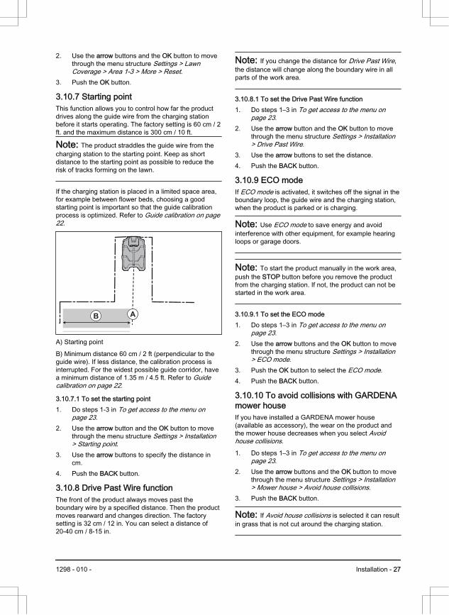
3.10.7 Starting pointThis function allows you to control how far the productdrives along the guide wire from the charging stationbefore it starts operating. The factory setting is 60 cm / 2ft. and the maximum distance is 300 cm / 10 ft.
Note: The product straddles the guide wire from thecharging station to the starting point. Keep as shortdistance to the starting point as possible to reduce therisk of tracks forming on the lawn.
If the charging station is placed in a limited space area,for example between flower beds, choosing a goodstarting point is important so that the guide calibrationprocess is optimized. Refer to Guide calibration on page22.
B A
A) Starting point
B) Minimum distance 60 cm / 2 ft (perpendicular to theguide wire). If less distance, the calibration process isinterrupted. For the widest possible guide corridor, havea minimum distance of 1.35 m / 4.5 ft. Refer to Guidecalibration on page 22.
3.10.7.1 To set the starting point1. Do steps 1-3 in To get access to the menu on
page 23.2. Use the arrow button and the OK button to move
through the menu structure Settings > Installation> Starting point.
3. Use the arrow buttons to specify the distance incm.
4. Push the BACK button.
3.10.8 Drive Past Wire functionThe front of the product always moves past theboundary wire by a specified distance. Then the productmoves rearward and changes direction. The factorysetting is 32 cm / 12 in. You can select a distance of20-40 cm / 8-15 in.
Note: If you change the distance for Drive Past Wire,the distance will change along the boundary wire in allparts of the work area.
3.10.8.1 To set the Drive Past Wire function1. Do steps 1–3 in To get access to the menu on
page 23.2. Use the arrow button and the OK button to move
through the menu structure Settings > Installation> Drive Past Wire.
3. Use the arrow buttons to set the distance.4. Push the BACK button.
3.10.9 ECO modeIf ECO mode is activated, it switches off the signal in theboundary loop, the guide wire and the charging station,when the product is parked or is charging.
Note: Use ECO mode to save energy and avoidinterference with other equipment, for example hearingloops or garage doors.
Note: To start the product manually in the work area,push the STOP button before you remove the productfrom the charging station. If not, the product can not bestarted in the work area.
3.10.9.1 To set the ECO mode1. Do steps 1–3 in To get access to the menu on
page 23.2. Use the arrow buttons and the OK button to move
through the menu structure Settings > Installation> ECO mode.
3. Push the OK button to select the ECO mode.4. Push the BACK button.
3.10.10 To avoid collisions with GARDENAmower houseIf you have installed a GARDENA mower house(available as accessory), the wear on the product andthe mower house decreases when you select Avoidhouse collisions.
1. Do steps 1–3 in To get access to the menu onpage 23.
2. Use the arrow buttons and the OK button to movethrough the menu structure Settings > Installation> Mower house > Avoid house collisions.
3. Push the BACK button.
Note: If Avoid house collisions is selected it can resultin grass that is not cut around the charging station.
1298 - 010 - Installation - 27

3.10.11 Frost SensorThe grass is extra sensitive to wear if the yard iscovered with frost. If the Frost Sensor is activated, theproduct is not allowed to start to cut the grass if thetemperature is below 5° C / 41° F.
Note: The frost sensor is located inside the chassisand there can be a delay compared to the ambienttemperature.
3.10.11.1 To set the Frost Sensor1. Do steps 1–3 in To get access to the menu on
page 23.2. Use the arrow buttons and the OK button to move
through the menu structure Settings > Installation> Frost Sensor.
3. Push the OK button to select Frost Sensor.4. Push the BACK button.
3.10.12 GeneralIn General you can change the general settings of theproduct.
3.10.12.1 To set the time & date1. Do steps 1–3 in To get access to the menu on
page 23.2. Use the arrow buttons and the OK button to move
through the menu structure Settings > General >Time & Date.
3. Use the arrow buttons to set the time and thenpush the BACK button.
4. Use the arrow buttons to set the date and thenpush the BACK button.
5. Use the arrow buttons to set the time format andthen push the BACK button.
6. Use the arrow buttons to set the date format andthen push the BACK button.
3.10.12.2 To set the language1. Do steps 1–3 in To get access to the menu on
page 23.2. Use the arrow buttons and the OK button to move
through the menu structure Settings > General >Language.
3. Use the arrow buttons to select language and thenpush the BACK button.
3.10.12.3 To set the country1. Do steps 1–3 in To get access to the menu on
page 23.2. Use the arrow buttons and the OK button to move
through the menu structure Settings > General >Country.
3. Use the arrow buttons to select country and thenpush the BACK button.
3.10.12.4 To set the unit format1. Do steps 1–3 in To get access to the menu on
page 23.2. Use the arrow buttons and the OK button to move
through the menu structure Settings > General >Unit format.
3. Use the arrow buttons to select unit format andthen push the BACK button.
3.10.12.5 To reset all user settings1. Do steps 1–3 in To get access to the menu on
page 23.2. Use the arrow buttons and the OK button to move
through the menu structure Settings > General >Reset all user settings.
3. Use the right arrow button to select Proceed withreset of all user settings?
4. Push the OK button to reset all the user settings.
Note: Security level, PIN code, Loop signal,Messages, Date & Time, Language and Countrysettings are not reset.
3.10.12.6 The About menuThe About menu displays information about the product,for example serial number and firmware versions.
3.10.13 GARDENA smart system
Only for smart SILENO city and smart SILENO life.
Note: Make sure that the smart product is fullyinstalled in the work area before you include it into theGARDENA smart system app. Refer to Installation onpage 14.
The product can connect to mobile devices that have theGARDENA smart system app installed. The GARDENAsmart system makes it possible with wireless interactionbetween your smart product and the GARDENA smartsystem.
In the smart system menu in the product you can:
• enable your smart product to include with orexclude from the GARDENA smart system app.
• check the status of the wireless connection to thesmart system.
When the smart product is part of the smart system,some menus in the product display are disabled. Youcan still see all of the settings in the product but somecan only be changed with the GARDENA smart system
28 - Installation 1298 - 010 -

app. The following settings are blocked in the menuselection of the smart product:
• Schedule• Time & Date• Language• Country
3.10.13.1 To set the Activate Inclusion ModeIn order to include your smart product into theGARDENA smart system app:
1. Do steps 1–3 in To get access to the menu onpage 23.
2. Use the arrow buttons and the OK button to enterthe menu smart system.
3. Use the right arrow button and the OK button toselect Yes to Activate Inclusion Mode.
4. Use the up/down arrow buttons to enter the PINcode and push the OK button.
5. The inclusion code is shown in the product display.6. Follow the instructions in the GARDENA smart
system app.
The inclusion sequence might take several minutes.Once the inclusion has succeeded you will automaticallyreturn to the product start screen. If the inclusion by anyreason fails, try again.
3.10.13.2 Inclusion in the AppThe inclusion of all GARDENA smart devices takesplace over the smart system app.
To download the GARDENA smart system app1. Download the GARDENA smart system app from
App Store or Google Play.2. Open the app and register as a user.3. Log in and choose Include device from the start
page in the app.4. Follow the instructions in the app.
Note: The smart gateway needs internet connectionto be able to include the product to the app.
3.10.13.3 To select Exclude deviceIf you exclude the device, there will be nocommunication between the product and the GARDENAsmart system.
1. Do steps 1–3 in To get access to the menu onpage 23.
2. Use the arrow buttons and the OK button to movethrough the menu structure smart system >Exclude device.
3. Push the OK button.
Note: The product must be manually deleted from thelist of products in the GARDENA smart system app.
3.10.13.4 To do a check of the status for GARDENAsmart systemWhen the product is connected to smart systemgateway, you can do a check of the connection status.
1. Do steps 1–3 in To get access to the menu onpage 23.
2. Use the arrow buttons and the OK button to movethrough the menu structure smart system > Status.
Note: The Status is either connected Yes or notconnected No. The Signal strength is either Good, Pooror Bad. Put the charging station in a location with Signalstrength - Good, for the best smart system performance.
1298 - 010 - Installation - 29

4 Operation4.1 The ON/OFF button
WARNING: Read the safetyinstructions carefully before you start theproduct.
WARNING: Keep your hands and feetaway from the rotating blades. Do not putyour hands or feet close to or under theproduct when the product is switched on.
WARNING: Do not use the productwhen persons, especially children, oranimals are in the work area.
• Push the ON/OFF button for 3 seconds to switchon the product. The product is active when theindicator lamp on the keypad is lit.
• Push the ON/OFF button for 3 seconds to switchoff the product.
• The product is in power save mode if the indicatorlamp flashes. Push the ON/OFF button for 3seconds to switch on the product.
4.1.1 The indicator lamp
WARNING: It is only safe to carry outinspection or maintenance on the productwhen the product is disabled. The product isdisabled when the lamp on the keypad is notlit.
The indicator lamp on the keypad is an important statusindicator:
• The product is active if the indicator lamp lightscontinuously.
• The product is in power save mode if the indicatorlamp flashes. Push the ON/OFF button for 3seconds to make the product active again.
• The product is disabled when the indicator lamp isnot lit.
4.2 To start the product1. Open the hatch to the keypad.2. Push the ON/OFF button for 3 seconds. The
display is lit up.3. Use the up/down arrow buttons and the OK button
to enter the PIN code.
4. Select the desired operating mode and confirmwith the OK button. Refer to Operating modes onpage 30.
5. Close the hatch.
Note: The first weeks after installation the perceivedsound level when cutting the grass may be higher thanexpected. When the product has cut the grass for sometime, the perceived sound level is much lower.
4.3 Operating modesPush the Mode button to select the following operatingmodes:
• Main area• Secondary area• Park• Park / Schedule• Override schedule• Spot cutting
30 - Operation 1298 - 010 -

4.3.1 Main areaMain area is the standard operating mode where theproduct mows and charges automatically.
4.3.2 Secondary areaTo mow secondary areas the operating modeSecondary area must be selected. In this mode, theoperator must move the product manually between themain area and the secondary area. The product mowsfor a selected period of time or until the battery is empty.When the battery is empty the product stops. Put theproduct in the charging station to charge the battery.When the battery is charged, the product moves out ofthe charging station and stops. The product is nowprepared to start operation, but needs confirmation fromthe operator first. In the Secondary area mode, theproduct operates for a selected period of time or until thebattery is empty.
Note: If you want to cut the main area after the batteryis charged, set the product to Main area mode beforeyou put the product in the charging station.
4.3.3 ParkOperating mode Park means that the product returns tothe charging station where it remains until a differentoperating mode is selected.
4.3.4 Park / ScheduleOperating mode Park / Schedule means that the productgoes back to the charging station where it stays until thenext schedule. If the product has operated the maximumcutting time for the day, it will start to operate again thenext day. Refer to Make an estimate of the necessaryoperating time on page 23.
4.3.5 Override scheduleSelect Override schedule to temporarily override theschedule settings. You can select to override theschedule settings for 3 hours. The product can not beset to cut more than the maximum cutting time for eachday.
4.3.6 Spot cuttingThe Spot cutting function is activated with the STARTbutton and is useful for quickly mowing an area wherethe grass has been mown less than in other parts of theyard. You must manually move the product to thechosen area.
Spot cutting means that the product mows in a spiralpattern in order to cut the grass in the area where it wasstarted. When this is done, the product automaticallyswitches back to Main area or Secondary area.
4.4 To stop the product1. Push the STOP button on top of the product.
The product stops and the cutting motor stops.
4.5 To switch off the product1. Push the STOP button.2. Open the hatch.3. Push the ON/OFF button for 3 seconds.
4. The product shuts down.5. Check that the indicator lamp on the keypad is not
lit.
4.6 To charge the battery
WARNING: Only charge the productusing a charging station which is intendedfor it. Incorrect use may result in electricshock, overheating or leakage of corrosiveliquid from the battery.
In the event of leakage of electrolyte flushwith water and seek medical help if it comesin contact with the eyes etc.
When the product is new or has been stored for a longperiod, the battery can be empty and needs to becharged before starting. In the Main area mode, theproduct automatically alternates between mowing andcharging.
1. Push the ON/OFF for 3 seconds button to start theproduct.
2. Place the product in the charging station. Slide theproduct in as far as possible to ensure propercontact between the product and the chargingstation. Refer to contact and charging plates in Product overview on page 4
1298 - 010 - Operation - 31

3. The display shows a message that charging is inprogress.
4.7 Adjust the cutting height
CAUTION: During the first weeks aftera new installation, the cutting height must beset to MAX to avoid damaging the loop wire.After this, the cutting height can be loweredstep by step every week until the desiredcutting height has been reached.
The cutting height can be varied from MIN (2 cm / 0.8in.) to MAX (5 cm / 2 in.).
4.7.1 To adjust the cutting height1. Push the STOP button to stop the product.2. Open the hatch.
3. Turn the knob to the required position.• Turn clockwise to increase the cutting height.• Turn counter-clockwise to decrease the
cutting height.4. Close the hatch.
32 - Operation 1298 - 010 -

5 Maintenance5.1 Introduction - maintenance
WARNING: The product must beswitched off before any maintenance isdone. The product is disabled when the LEDstatus indicator is not lit.
WARNING: Wear protective gloves.
For better operation and longer service life, make sureto clean the product regularly and replace worn parts. Allmaintenance and servicing must be done according toGARDENA's instructions. Refer to Warranty on page52.
When the product is first used, the blade disc andblades should be inspected once a week. If the amountof wear during this period has been low, the inspectioninterval can be increased.
It is important that the blade disc rotates easily. Theedges of the blades should not be damaged. Thelifetime of the blades varies immensely and depends forinstance on:
• Operating time and size of the work area.• Type of grass and seasonal growth.• Soil, sand and use of fertilizers.• The presence of objects such as cones, windfalls,
toys, tools, stones, roots and the like.
The normal life is 4 to 7 weeks when used underfavorable conditions. Refer to To replace the blades onpage 34 on how to replace the blades.
Note: Working with blunt blades gives a poorermowing result. The grass is not cut cleanly and moreenergy is needed resulting in the product not mowingsuch a large area.
5.2 Clean the product
CAUTION: Do not use a high-pressurewasher to clean the product. Do not usesolvents for cleaning.
The product does not operate satisfactorily in slopes ifthe wheels are blocked with grass. Use a soft brush toclean the product.
GARDENA recommends to use a special cleaning andmaintenance kit as an accessory. Speak to yourGARDENA service.
5.2.1 Chassis and blade discInspect the blade disc and blades once a week.
1. Push the STOP button.2. Push the ON/OFF button for 3 seconds to switch
off the product.3. Check that the indicator lamp on the keypad is not
lit.4. If the product is dirty, clean it by using a brush or a
water hose. Do not use a high-pressure washer.5. Lift the product onto its side.6. Clean the blade disc and chassis using for
example a dish brush. At the same time, checkthat the blade disc rotates freely in relation to thefoot guard. Also, check that the blades are intactand can pivot freely.
5.2.2 WheelsClean around the wheels. Grass on the wheels canimpact on how the product performs in slopes.
5.2.3 The body of the productUse a moist, soft sponge or cloth to clean the body ofthe product. If the body of the product is dirty, use a mildsoap solution to clean it.
5.2.4 Charging station
WARNING: Disconnect the powersupply from the power outlet before anymaintenance, or cleaning of charging stationor power supply.
Clean the charging station regularly from grass, leaves,twigs and other objects that may impede docking.
1298 - 010 - Maintenance - 33

5.3 Replace the blades
WARNING: Use blades and screws ofthe right type. GARDENA can onlyguarantee safety when using original blades.Only replacing the blades and reusing thescrew can result in a screw wearing duringmowing. The blades can then be propelledfrom under the body and cause seriousinjury.
Replace worn or damaged parts for safety reasons.Even if the blades are intact, they should be replaced ona regular basis for the best mowing result and lowenergy usage. All 3 blades and screws must be replacedat the same time to obtain a balanced cutting system.Use GARDENA original blades embossed with thecrowned H-mark logotype, refer to Warranty on page52.
5.3.1 To replace the blades1. Push the STOP button.2. Open the hatch.3. Push the ON/OFF button for 3 seconds to switch
off the product.
4. Check that the indicator lamp on the keypad is notlit.
5. Turn the product upside down. Place the producton a soft and clean surface to avoid scratching thebody and the hatch.
6. Remove the 3 screws. Use a straight slot or cross-tip screwdriver.
7. Remove each blade and screw.8. Fasten new blades and screws.9. Check that the blades can pivot freely.
5.4 Firmware updateIf service is done by GARDENA service then availablefirmware updates are downloaded to the product by theservice technician. Owners of GARDENA products canupdate the firmware if this is initiated by GARDENA.Registered users are in that case notified.
5.4.1 To update the firmware1. Open the battery hatch. Refer to To replace the
battery on page 35.2. Plug in a USB printer cable (USB A and USB B
contacts) in the product and your computer. TheUSB printer cable is available as an accessory.
3. Go to www.gardena.com, search for and downloadthe firmware update tool and follow theinstructions.
4. Remove the USB printer cable and close thebattery hatch.
34 - Maintenance 1298 - 010 -

5.5 Battery
WARNING: Only charge the productusing a charging station which is intendedfor it. Incorrect use may result in electricshock, overheating or leakage of corrosiveliquid from the battery. In the event ofleakage of electrolyte flush with water andseek medical help if it comes in contact withthe eyes etc.
WARNING: Use only original batteriesrecommended by the manufacturer. Productsafety cannot be guaranteed with otherbatteries. Do not use non-rechargeablebatteries.
CAUTION: The battery must charge acomplete cycle before winter storage. If thebattery is not fully charged it can bedamaged and in certain cases be rendereduseless.
If the operating time for the product is shorter thannormal between charges, this indicates that the batteryis getting old and eventually needs replacing.
Note: Battery life is dependent on the length of theseason and how many hours a day the product isoperating. A long season or many hours of use a daymeans that the battery must be replaced more regularly.The battery is fine as long as the product maintains awell-cut lawn.
5.5.1 To replace the battery
WARNING: The product must bedisconnected from the supply mains whenremoving the battery.
1. Push the ON/OFF button for 3 seconds to switchoff the product. Check that the indicator lamp onthe keypad is not lit.
2. Set the cutting height to MIN.3. Turn the product upside down. Place the product
on a soft and clean surface to avoid scratching thebody and the display cover.
4. Clean around the battery cover.5. Unscrew the screws to the battery cover (Torx 20)
and remove the battery cover.
6. Release the latch of the connector (A) and pull itupwards.
B
A
B
CAUTION: Do not pull the cables.
7. Release the latch of the battery and lift up thebattery (B).
8. Put the new battery into place in the product.
Note: Fit the battery cover without clamping thecables. If the seal on the battery cover is visiblydamaged, the entire battery cover must bereplaced.
9. Connect the cable.10. Carefully tighten screws for the battery cover (Torx
20).
5.6 Winter serviceTake your product to your GARDENA central service forservice prior to winter storage. Regular winter servicewill maintain the product in good condition and createthe best conditions for a new season without anydisruptions.
Service usually includes the following:
• Thorough cleaning of the body, the chassis, theblade disc and all other moving parts.
• Testing of the product’s function and components.
1298 - 010 - Maintenance - 35

• Checking and, if required, replacing wear itemssuch as blades and bearings.
• Testing the product’s battery capacity as well as arecommendation to replace battery if necessary.
• If new firmware is available, the product isupdated.
36 - Maintenance 1298 - 010 -

6 Troubleshooting
6.1 Introduction - troubleshootingIn this chapter you can find information and help about faults and symptoms of the product. You can find moreinformation and FAQ (Frequently Asked Questions) on www.gardena.com.
6.1.1 To get access to the Quick info menuTechnical data, values and information about the historyof the product can be found in the Quick info menu. Ifyou speak to GARDENA central service for a solution to
a problem, they can tell you to access the informationthat is available in this menu.
• Push the Menu button for 3 seconds to enter theQuick info menu.
6.2 Fault messagesThe fault messages in the table below are shown in the display of the product. Speak to your GARDENArepresentative if the same message shows frequently.
Message Cause Action
Wheel motorblocked, left/right
Grass or other object around the drive wheel. Remove grass or other object.
Cutting systemblocked
Grass or other object around the blade disc. Remove grass or other object.
The blade disc is in water. Move the product and prevent the collectionof water in the work area.
The grass is too high. Cut the grass before you install the product.Make sure that the grass is maximum 4 cm /1.6 in.
Trapped The product is behind a number of obstaclesin a small area.
Remove the obstacles or put the boundarywire around the obstacle to make an island.Refer to To make an island on page 17.
Outside working area A section of boundary wire is put across theother section of boundary wire to the charg-ing station.
Make sure that the boundary wire is connec-ted correctly.
The boundary wire is too near the edge ofthe work area.
Make sure that the boundary wire is installedcorrectly. Refer to To install the boundarywire on page 20.
The work area slopes much by the boundaryloop.
The boundary wire is put in the incorrect di-rection around an island.
Interference to the boundary wire from metalobjects such as fences, reinforcement steelor buried cables near by.
Move the boundary wire.
The product can not find the correct loop sig-nal because of interference with a loop signalfrom a different product installation near by.
Put the product in the charging station andgenerate a new loop signal.
1298 - 010 - Troubleshooting - 37

Message Cause Action
Empty battery The product cannot find the charging station. Change the position of the guide wire. Referto To install the guide wire on page 20.
The battery is at the end of its life cycle. Replace the battery. Refer to Battery onpage 35.
The antenna of the charging station is defec-tive.
Do a check if the indicator lamp in the charg-ing station flashes red. Refer to Indicatorlamp in the charging station on page 43.
The charging plates on the product or con-tact plates on the charging station are defec-tive because of corrosion.
Clean the charging and contact plates usinga fine grade emery cloth. If the problem staysspeak to your authorized service technician.
Wrong PIN code Incorrect PIN code has been entered. 5 triesare permitted to enter the correct PIN code,and then the keypad is blocked for a periodof time.
Enter the correct PIN code. Speak to yourGARDENA customer service if you forget thePIN code.
No drive The product has got caught in something andhas been slipping.
Free the product and correct the cause ofproblem. If it is because of wet grass, waituntil the lawn is dry before you use the prod-uct.
The work area includes a steep slope. Steep slopes must be isolated. Refer to Toexamine where to put the boundary wire onpage 15.
The guide wire is not put diagonally in theslope.
Make sure that the guide wire is installed di-agonally across the slope. Refer to To exam-ine where to put the guide wire on page 18.
Wheel motor overloa-ded, left/right
Grass or other object around the drive wheel. Remove grass or object from the drivewheel.
Collision sensorproblem, front/rear
The product body cannot move freely aroundits chassis.
Make sure that the product body can movefreely around its chassis. If the problem staysspeak to your authorized service technician.
Alarm! Mower switch-ed off
The alarm has started because the producthad been switched off.
Adjust the security level in the Securitymenu. Refer to Security - Advanced on page25.
Alarm! Mower stop-ped
The alarm has started because the producthas been stopped.
Alarm! Mower lifted The alarm has started because the producthas been lifted.
Alarm! Mower tilted The alarm has started because the producthas been tilted.
38 - Troubleshooting 1298 - 010 -

Message Cause Action
Charging stationblocked
The contact between the charging plates onthe product and the contact plates on thecharging station is not good. The product hasmade a number of tries to charge.
Put the product in the charging station andmake sure that the charging plates and con-tact plates are connected.
An object prevents the product to enter thecharging station.
Remove the object.
The charging station is tilted or bent. Put the baseplate on level ground.
The guide wire is not installed correctly. Install the guide wire correctly. Refer to Toinstall the guide wire on page 20.
Stuck in charging sta-tion
An object prevents the product to move outfrom the charging station.
Remove the object.
Upside down The product is in an incorrect position, theproduct is tilting too much or is upside down.
Put the product in the correct position.
Needs manual charg-ing
The product is set to the Secondary area op-erating mode.
Put the product in the charging station.
Next start hh:mm The schedule setting prevents the productfrom operating.
Change the schedule settings. Refer to Todo the schedule settings on page 23.
The product has operated the maximum cut-ting time for the day.
Usual operation of the product.
The time or date in the product is not correct. Set the time or date. Refer to To set the time& date on page 28.
Today's mowingcompleted
The product has operated the maximum cut-ting time for the day.
Usual operation of the product. Refer to Make an estimate of the necessary operatingtime on page 23.
Lifted The lift sensor has been enabled becausethe product has been lifted.
Make sure that the product body can movefreely around its chassis. Remove or createan island around objects that can cause thechassis to be lifted. If the problem staysspeak to your authorized service technician.
Wheel drive problem,right/left
Grass or other object around the drive wheel. Clean the wheels and around the wheels.
Electronic problem Temporary electronic or firmware relatedproblem in the product.
Restart the product. If the problem staysspeak to your authorized service technician.
Loop sensor prob-lem, front/rear
Tilt sensor problem
Temporary problem
Invalid sub-devicecombination
Temporary batteryproblem
Safety function faulty
Charging systemproblem
Incorrect type of battery. Use original batteries recommended by themanufacturer.
1298 - 010 - Troubleshooting - 39

Message Cause Action
Battery problem Temporary battery or firmware related prob-lem in the product.
Restart the product. If the problem staysspeak to your authorized service technician.
Incorrect type of battery. Use original batteries recommended by themanufacturer.
Battery temperatureoutside limits
The temperature in the battery is too high ortoo low to start operation.
The product will start to operate when thetemperature is in limits.
Charging current toohigh
Incorrect or defective power supply unit. Restart the product. If the problem staysspeak to your authorized service technician.
Connectivity problem Problem on the connectivity circuit board inthe product.
Restart the product. If the problem staysspeak to your authorized service technician.
Connectivity settingsrestored
The connectivity settings was restored be-cause of a fault.
Do a check of the connectivity settings andchange the settings if necessary.
Poor signal quality The connectivity circuit board in the productis assembled incorrectly.
Examine if the connectivity circuit board isassembled correctly. If the problem staysspeak to your authorized service technician.
The product is in an incorrect position, theproduct is tilting too much or is upside down.
Put the product in the correct position.
40 - Troubleshooting 1298 - 010 -

Message Cause Action
No loop signal The power supply or low-voltage cable arenot connected.
If the LED status indicator on the chargingstation is not lit, it shows that there is nopower. Examine the power outlet connectionand the residual-current device. Make surethat the low-voltage cable is connected to thecharging station.
The power supply or low-voltage cable aredamaged or not connected.
Replace the power supply or low-voltage ca-ble.
The boundary wire is not connected to thecharging station.
Connect the boundary wire to the chargingstation. Replace the connectors if damaged.Refer to To install the boundary wire on page20.
The boundary wire is damaged. Do a check of the LED status indicator on thecharging station. If it shows damage in theboundary wire, replace the damaged sectionwith new boundary wire.
The product has tried to start but it is not inthe charging station and ECO mode is ena-bled.
Put the product in the charging station, startthe product and close the hatch.
A section of the boundary wire is across theother section of boundary wire to and froman island.
Install the boundary wire in the correct direc-tion around the island. Refer to To install theboundary wire on page 20.
Problem with the pairing between the productand the charging station.
Put the product in the charging station andmake a new loop signal. Refer to To make anew loop signal on page 25.
Interference from metal objects such as fen-ces, reinforcement steel or buried cablesnear by.
Move the boundary wire and/or make islandsin the work area to increase the signalstrength.
The product is too far from the boundarywire.
Install the boundary wire to make all parts ofthe work area maximum 15 m / 50 ft. fromthe boundary wire.
Mower tilted The product is tilted more than the maximumangle.
Move the product to a level area.
Connection NOTchanged
The loop signal was not changed because ofan error.
Make a New loop signal a number of times.Refer to To make a new loop signal on page25. If the problem stays speak to your au-thorized service technician.
1298 - 010 - Troubleshooting - 41

6.3 Information messagesThe information messages in the table below are shown in the display of the product. Speak to your GARDENArepresentative if the same message shows frequently.
Message Cause ActionLow battery The product cannot find the charging station. Change the position of the guide wire. Refer
to To install the guide wire on page 20.
The battery is at the end of its life cycle. Replace the battery. Refer to Battery onpage 35.
The antenna of the charging station is defec-tive.
Do a check if the indicator lamp in the charg-ing station flashes red. Refer to Indicatorlamp in the charging station on page 43.
The charging plates on the product or con-tact plates on the charging station are defec-tive because of corrosion.
Clean the charging and contact plates usinga fine grade emery cloth. If the problem staysspeak to your approved servicing dealer.
Settings restored A Reset all user settings has been done. Usual operation of the product.
Guide not found The guide wire is not connected to the charg-ing station.
Connect the guide wire to the charging sta-tion. Refer to To install the guide wire onpage 20.
Damage in the guide wire. Replace the damaged section with newguide wire.
The guide wire is not connected to the boun-dary loop.
Connect the guide wire correctly to the boun-dary loop. Refer to To install the guide wireon page 20.
Guide calibrationfailed
The product has not calibrated the guide wirebecause of an error.
Install the guide wire correctly. Refer to Toinstall the guide wire on page 20.
Guide calibrationdone
The product has calibrated the guide wire. Usual operation of the product.
Connection changed New loop signal changed. Usual operation of the product.
42 - Troubleshooting 1298 - 010 -

6.4 Indicator lamp in the charging stationThe indicator lamp in the charging station must show a solid or flashing green light for a correct installation. If not,follow the instructions in the troubleshooting table below.
Speak to your GARDENA service for more information.
Light Cause Action
Green solid light Good signals. Usual operation of the product.
Green flashing light The signals are good and ECO mode is ena-bled.
Usual operation of the product. Refer to ECOmode on page 27.
Blue flashing light The boundary wire is not connected to thecharging station.
Make sure that the boundary wire is correctlyinstalled in the charging station. Refer to Toinstall the boundary wire on page 20.
Damage in the boundary wire. Find out where the damage is. Replace thedamaged section with new boundary wire.
Yellow flashing light The guide wire is not connected to the charg-ing station.
Make sure that the guide wire is correctly in-stalled in the charging station. Refer to To in-stall the guide wire on page 20
Damage in the guide wire. Find out where the damage is. Replace thedamaged section with new guide wire.
Red flashing light Interference in the antenna of the chargingstation.
Speak to your GARDENA service.
Red solid light Error in the circuit board or incorrect powersupply in the charging station. The error mustbe corrected by your GARDENA service
Speak to your GARDENA service.
1298 - 010 - Troubleshooting - 43

6.5 SymptomsIf the product does not operate as usual, follow the symptoms table below. Speak to your GARDENA customerservice if you cannot find the cause for the fault.
Symptoms Cause Action
The product has diffi-culty docking.
The guide wire is not put straight in a lineand correct distance from the charging sta-tion.
Do a check of the installation of the chargingstation. Refer to To install the charging sta-tion on page 19.
The guide wire is not put in the slot in thecharging station plate.
Make sure that the guide wire is put straightin a line and put in the slot in the chargingstation plate. Refer to To install the guidewire on page 20.
The charging station is not on a level sur-face.
Put the charging station on a level surface.Refer to To examine where to put the charg-ing station on page 14.
The product operatesat the wrong time.
The time or the date in the product is not cor-rect.
Set the time or date. Refer to To set the time& date on page 28.
The start and stop times for operating are in-correct.
Change the schedule settings. Refer to Toreset the schedule setting on page 24.
The product vibrates. The cutting system is not in balance becauseof damaged blades.
Examine the blades and screws and replacethem if necessary. Refer to Replace theblades on page 34.
The cutting system is not in balance becauseof too many blades in the same position.
Do a check that only one blade is attached toeach screw.
Different thickness of blades are installed onthe product.
Do a check if the blades are of different thick-ness and replace if necessary.
The product oper-ates, but the bladedisc does not rotate.
The product searches for the charging sta-tion, or is moving to the starting point.
Usual operation for the product. The bladedisc does not rotate when the product issearching for the charging station.
The product operatesfor shorter periodsthan usual betweencharges.
Grass or other object causes a blockage tothe blade disc.
Remove and clean the blade disc. Refer to Clean the product on page 33.
The battery is at the end of its life cycle. Replace the battery. Refer to Battery onpage 35.
Blunt blades. More energy is necessarywhen cutting the grass.
Replace the blades. Refer to Replace theblades on page 34.
Mowing and chargingtimes are shorterthan usual.
The battery is at the end of its life cycle. Replace the battery. Refer to Battery onpage 35.
44 - Troubleshooting 1298 - 010 -

Symptoms Cause Action
The product isparked for hours inthe charging station.
The product has operated the maximum cut-ting time for the day.
Usual operation for the product. Refer to Make an estimate of the necessary operatingtime on page 23.
The STOP button has been pushed. Open the hatch, enter the PIN code andpush the OK button. Push the Start buttonand then close the hatch.
Parking mode is enabled. Change the operating mode. Refer to Oper-ating modes on page 30.
The product does not operate if the batterytemperature is too high or too low.
Make sure that the charging station is put inan area with protection from the sun.
Uneven mowing re-sults.
The product operates for a small number ofhours per day.
Increase the cutting time. Refer to To set theschedule on page 23.
For the shape of the work area it is necessa-ry to adjust the settings for Lawn Coverageto cover all parts of the work area.
Change the settings of the areas where theproduct starts to cut and how often. Refer to To set the Lawn Coverage function on page25.
The work area is too large. Decrease the size of the work area or extendthe schedule. Refer to To set the scheduleon page 23.
Blunt blades. Replace all the blades. Refer to Replace theblades on page 34.
Long grass in relation to the set cuttingheight.
Increase the cutting height and then lower itwhen the grass is shorter.
Collection of grass by the blade disc oraround the motor shaft.
Remove the collection of grass and clean theproduct. Refer to Clean the product on page33.
The battery state ofcharge is high, butthe product goesback to the chargingstation.
To prevent to become blocked in a smallarea, the product follows the guide wire tothe charging station.
Usual operation for the product.
6.6 Find breaks in the loop wireBreaks in the loop wire are usually the result ofunintentional physical damage to the wire such as whengardening with a shovel. In countries with ground frost,also sharp stones that move in the ground can damagethe wire. Breaks can also occur due to the wire beingstretched excessively during installation.
Mowing the grass too low right after the installation candamage wire insulation. Damage to the insulation maynot cause disruptions until several weeks or monthslater. To avoid this, always select the maximum cuttingheight the first weeks after installation and then lowerthe height one step at a time every second week untilthe desired cutting height has been reached.
A defective splicing of the loop wire can also lead todisruptions several weeks after the splice was done. Afaulty splice can, for example, be the result of thecoupler not being pressed together hard enough with a
pair of pliers, or that a coupler of lower quality than theoriginal coupler has been used. Please first check allknown splices before further troubleshooting is done.
A wire break can be located by gradually halving thedistance of the loop where the break may have occurreduntil there is only a very short section of the wire left.
The following method does not work if ECO mode isactivated. Make sure first that ECO mode is switchedoff. Refer to ECO mode on page 27.
1. Check that the indicator lamp in the chargingstation flashes blue, which indicates a break in theboundary loop. Refer to Indicator lamp in thecharging station on page 43.
1298 - 010 - Troubleshooting - 45

2. Check that the boundary wire connections to thecharging station are properly connected and notdamaged. Check that the indicator lamp in thecharging station is still flashing blue.
R
GUIDE
L
POWER
3. Switch the connections between the guide wireand the boundary wire in the charging station.
Start by switching connection L and GUIDE.
If the indicator lamp is flashing yellow, then thebreak is somewhere on the boundary wire betweenL and the point where the guide wire is connectedto the boundary wire (thick black line in theillustration).
Guide
GUIDEL
To rectify the fault you will need boundary wire,connector(s) and coupler(s):
a) If the suspected boundary wire is short then theeasiest way is to exchange all of the boundary wirebetween L and the point where the guide wire isconnected to the boundary wire (thick black line).
b) If the suspected boundary wire is long (thickblack line) then do as follows: Put L and GUIDEback to their original positions. Then disconnect R.Connect a new loop wire to R. Connect the otherend of this new loop wire at the middle of thesuspected wire section.
46 - Troubleshooting 1298 - 010 -

R
If the indicator lamp now is flashing yellow, thenthe break is somewhere in the wire between thedisconnected end to the point where the new wireis connected (thick black line below). In that case,move the connection for the new wire closer to thedisconnected end (roughly at the middle of thesuspected wire section) and check again if theindicator lamp is green.
Continue until only a very short section of the wireremains which is the difference between a solidgreen light and a flashing blue light. Then followinstruction in step 5 below.
4. If indicator lamp still flashes blue in step 3above: Put L and GUIDE back in their originalpositions. Then switch R and GUIDE. If indicatorlamp now is lit with a solid green light thendisconnect L and connect a new boundary wire toL. Connect the other end of this new wire at themiddle of the suspected wire section. Follow thesame approach as in 3a) and 3b) above.
5. When the break is found, the damaged sectionmust be replaced with a new wire. Always useoriginal couplers.
1298 - 010 - Troubleshooting - 47

7 Transportation, storage and disposal7.1 TransportationThe supplied Li-ion batteries obey the Dangerous GoodsLegislation requirements.
• Obey all applicable national regulations.• Obey the special requirement on package and
labels for commercial transportations, including bythird parties and forwarding agents.
7.2 Storage• Fully charge the product. Refer to To charge the
battery on page 31.• Switch off the product. Refer to The ON/OFF
button on page 30.• Clean the product. Refer to Clean the product on
page 33.• Keep the product in a dry, frost free space.• Keep the product with all wheels on level ground
during storage.• If you keep the charging station indoors,
disconnect and remove the power supply and allthe connectors from the charging station. Put theend of each connector wire in a connectorprotection box.
Note: If you keep the charging station outdoors,do not disconnect the power supply and theconnectors.
• Speak to your GARDENA service for informationabout available storage accessories for yourproduct.
7.3 Disposal• Obey the local recycling requirements and
applicable regulations.• For questions about how to remove the battery,
refer to Battery on page 35.
48 - Transportation, storage and disposal 1298 - 010 -

8 Technical data
8.1 Technical dataData SILENO city
smart SILENO city
SILENO life
smart SILENO life
Dimensions
Length, cm / in. 55 / 21.7 58 / 22.8
Width, cm / in. 38 / 15.0 39 / 15.4
Height, cm / in. 23 / 9.1 23 / 9.1
Weight, kg / lb 7.3 / 16 8.3 / 18
Electrical system SILENO city
smart SILENO city
SILENO life
smart SILENO life
Battery, Lithium-Ion 18 V/2.0 Ah Art.No 590 21 42-02, 590 21 42-04, 584 85 28-03, 584 85 28-05
Battery, Lithium-Ion 18.25 V/2.0 Ah Art.No 590 21 42-03, 584 85 28-04
Power supply (28V DC), V AC 100-240 100-240
Low voltage cable length, m / ft. 5 / 16.4 5 / 16.4
Mean energy consumption at maximum use 4 kWh/month in a 500 m2
work area7 kWh/month in a 1250 m2
work area
Charge current, A DC 1 / 1.3 1.3
Type of Power Supply Unit2 ADP-40BR XX, ADP 28EW XX,FW7313/28/D/XX/Y/1.3/PI, FW7313/28/D/XX/Y/1.3, ADP28AR XX, FW7313/28/D/XX/Y/1.0/PI,FW7313/28/D/XX/Y/1.0
Average mowing time, min 65 65
Average charging time, min 75 / 60 60
Boundary wire antenna SILENO city
smart SILENO city
SILENO life
smart SILENO life
Operating Frequency Band, Hz 100-80000 100-80000
Maximum magnetic field3, dBuA/m 82 82
Maximum Radio-frequency power4, mW @60m <25 <25
2 XX, YY can be any alphanumeric characters or blank for marketing purpose only, no technical differences.3 Measured according to EN 303 447.4 Maximum active output power to antennas in the frequency band in which the radio equipment operates.
1298 - 010 - Technical data - 49

Sound data5 SILENO city
smart SILENO city
SILENO life
smart SILENO life
Measured sound power noise level, dB (A) 56 56
Noise emissions uncertainties KWA, dB (A) 2 2
Guaranteed sound power noise level, dB (A) 58 58
Sound pressure noise level at the operator’s ear6, dB (A) 45 45
The noise emission declarations conforms to EN 50636-2-107:2015
Mowing SILENO city
smart SILENO city
SILENO life
smart SILENO life
Cutting system 3 pivoted cutting blades
Cutting motor speed, rpm 2500 2500
Power consumption during cutting, W +/- 20 % 20 20
Cutting height, cm / in. 2-5 / 0.8-2 2-5 / 0.8-2
Cutting width, cm / in. 16 / 6.3 22 / 8.7
Narrowest possible passage, cm / in. 60 / 24 60 / 24
Maximum slope for cutting area, % 35 35
Maximum slope for boundary wire, % 10 10
Maximum length boundary wire, m / ft. 300 / 980 300 / 980
Maximum length guide loop7, m / ft. 150 / 490 150 / 490
IP-classification SILENO city
smart SILENO city
SILENO life
smart SILENO life
Product IPX5 IPX5
Charging station IPX5 IPX5
Power supply IP44 IP44
Bluetooth® SILENO city
smart SILENO city
SILENO life
smart SILENO life
Operating frequency band, MHz 2400 - 2484 2400 - 2484
Maximum transmitted power, dBm 8 8
5 Determined according to Directive 2006/42/EC and standard EN 50636-2-107.6 Sound pressure noise uncertainties KpA, 2-4 dB (A)7 The guide loop is the loop that if formed by the guide wire and the part of the boundary wire from the junction
with the guide wire to the right connection in the charging station.
50 - Technical data 1298 - 010 -

Internal SRD (short range device) SILENO city, SILENO life smart SILENO city, smartSILENO life
Operating frequency band, MHz - 863-870
Maximum transmitted power, dBm - 14
Free field radio range, approx. m - 100
Husqvarna AB does not guarantee full compatibility between the product and other types of wireless systems such asremote controls, radio transmitters, hearing loops, underground electric animal fencing or similar.
The products are made in England or the Czech Republic. See information on the rating plate. Refer to Introductionon page 3.
1298 - 010 - Technical data - 51

9 Warranty9.1 Warranty termsGARDENA warranty covers this product's functionalityfor a period of 2 years from date of purchase. Thewarranty covers serious faults relating to materials ormanufacturing faults. Within the warranty period, we willreplace the product or repair it at no charge if thefollowing terms are met:
• The product and the charging station may only beused in compliance with the instructions in thisOperator’s Manual. This manufacturer's warrantydoes not affect warranty entitlements against thedealer/retailer.
• End-users or non-authorized third parties must notattempt to repair the product.
Examples of faults which are not included in thewarranty:
• Damage caused by water seepage from using ahigh-pressure washer, or from being submergedunder water, for example when heavy rain formspools of water.
• Damage caused by lightning.• Damage caused by improper battery storage or
battery handling.• Damage caused by using a battery that is not a
GARDENA original battery.• Damage caused by not using GARDENA original
spare parts and accessories, such as blades andinstallation material.
• Damage to the loop wire.• Damage caused by non-authorized changing or
tampering with the product or its power supply.
The blades and wheels are seen as disposable and arenot covered by the warranty.
If an error occurs with your GARDENA product, pleasecontact GARDENA customer service for furtherinstructions. Please have the receipt and the product’sserial number at hand when contacting GARDENAcustomer service.
52 - Warranty 1298 - 010 -
10 EC Declaration of Conformity10.1 EC Declaration of ConformityHusqvarna AB, SE-561 82 Huskvarna, Sweden, tel:+46-36-146500, declares that the robotic lawn mowersGARDENA SILENO city, GARDENA smart SILENO city,GARDENA SILENO life and GARDENA smart SILENOlife with serial numbers dating 2020 week 40 andonwards (the year and week is clearly stated on therating plate, followed by the serial number), comply withthe requirements of the COUNCIL’S DIRECTIVE aslisted below including applied standards.
• Directive “relating to machinery” 2006/42/EC.• EN 60335-1:2012• EN 50636-2-107:2015• EN 62233:2008.
• Directive on ”restriction of use of certain hazardoussubstances” 2011/65/EU:• EN IEC 63000:2018
• Directive “relating to radio equipment” 2014/53/EU.Safety
• See directive 2006/42/EC above.
Electromagnetic compatibility
• EN 55032:2015• ETSI EN 301 489-17 V3.1.1
For GARDENA smart SILENO city and GARDENAsmart SILENO life:
• ETSI EN 301 489-3 V2.1.1
Efficient use of the spectrum
• Draft ETSI EN 303 447 V1.2.1_0.1.14• ETSI EN 300 328 V2.1.1
For GARDENA smart SILENO city and GARDENAsmart SILENO life:
• ETSI EN 300 220-1 V3.1.1• ETSI EN 300 220-2 V.3.1.1
The notified body RISE Research Institutes of SwedenAB has issued a type examination certificate with no.C900196 covering Art. 3.2 of 2014/53/EU.
1298 - 010 - EC Declaration of Conformity - 53

54 - EC Declaration of Conformity 1298 - 010 -

1298 - 010 - EC Declaration of Conformity - 55

2021-02-12
ORIGINAL INSTRUCTIONSWe reserve the right to make changes without prior notice. Copyright © 2021 GARDENA Manufacturing GmbH. All rights reserved.
114 23 32-26
InDesign P01 omslag P01_P02_a5.indd 2InDesign P01 omslag P01_P02_a5.indd 2