om manual is3000 ssw8
TRANSCRIPT

®
SOPHO iS3000 Series(SSW 805)
OM
CO
MM
AN
DS
MA
NU
AL
(MM
L)


® Issue:
SOPHO iS3000 Series(SSW 805)
OM
CO
MM
AN
DS
MA
NU
AL
(MM
L)
9908

A Publication ofPHILIPS BUSINESS COMMUNICATIONSHILVERSUM, THE NETHERLANDS
Order No.:
Manual No.:
Date:
Great care has been taken to ensure that the information contained in this handbook is accurate and complete. Should any errors or omissions be dicovered or should any user wish to make a suggestion for improving this handbook, he is invited to send the relevant details to:
PHILIPS COMMUNICATION SYSTEMSPHILIPS BUSINESS COMMUNICATIONSPRODUCT QUALITY & SUPPORTP.O. BOX 321200 JD HILVERSUMTHE NETHERLANDS
© PHILIPS BUSINESS COMMUNICATION SYSTEMS B.V.All right are reserved. Reproduction in whole or in part is prohibited without the written consent of the copyright owner.
1999
3522 009 05259
August 1999
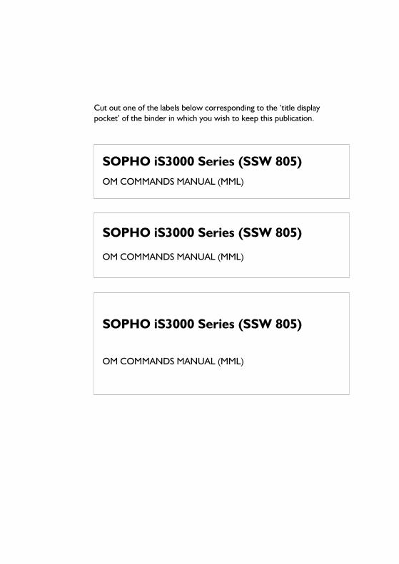
Cut out one of the labels below corresponding to the ‘title display pocket’ of the binder in which you wish to keep this publication.
SOPHO iS3000 Series (SSW 805)
OM COMMANDS MANUAL (MML)
SOPHO iS3000 Series (SSW 805)
OM COMMANDS MANUAL (MML)
SOPHO iS3000 Series (SSW 805)OM COMMANDS MANUAL (MML)


i
Tab
le o
f con
tent
s
AMENDMENTS ................................................................................................1
PREFACE...........................................................................................................3
1. INTRODUCTION .............................................................................................4
1.1. WHAT IS AN OM COMMAND ................................................................................. 41.2. OM COMMAND SYNTAX ........................................................................................ 41.3. REPRESENTATION OF OM COMMANDS............................................................... 51.4. ON SCREEN HELP FUNCTIONS ............................................................................. 61.5. KEYBOARD COMMANDS......................................................................................... 71.6. SYSTEM RESPONSES ................................................................................................. 71.7. EHWA STRUCTURE .................................................................................................. 8
2. ABBREVIATED NUMBERS ........................................................................... 11
3. ANALYSIS GROUP, COMPATIBILITY VALUE AND SERVICE PROFILE ...12
3.1. ANALYSIS GROUP AND COMPATIBILITY VALUE................................................ 123.2. SERVICE PROFILE .................................................................................................... 12
4. BACKUP MAINTENANCE.............................................................................14
4.1. UNIT COMPATIBILITY............................................................................................ 174.2. MAKING A FIRE COPY ............................................................................................ 18
4.2.1. Making a Fire Copy for a CCS System.......................................................... 184.2.2. Making a Fire Copy for a CPS or CPU-ME/MT System ............................... 18
5. BOUNDARIES, OPTIONS AND TIMERS .....................................................20
6. CALL FORWARDING .....................................................................................22
7. CAMP ON BUSY ............................................................................................24
8. COMMAND FILE EXECUTION .....................................................................25
8.1. NORMAL COMMAND FILES .................................................................................. 258.2. AUTHORITY OVERRULING COMMAND FILES.................................................... 27
9. DATA FUNCTIONS .......................................................................................28
9.1. COMPATIBILITY VALUES AND CONVERTORS.................................................... 289.1.1. Compatibility Values ..................................................................................... 299.1.2. Convertors.................................................................................................... 30
9.2. REMARKS ABOUT DOWNLOADING .................................................................... 319.3. SELECTIVE ANSWERING DNR............................................................................... 32
10. DATE, TIME AND EXCHANGE-ID ...............................................................34
11. DIGITAL ALARMS..........................................................................................36

ii
Table of contents
12. DISPLAY METERING .....................................................................................38
13. DNR/BSP-ID - LINE CIRCUIT/CENTRAL MODULE RELATIONS...............39
14. DOWNLOAD ..................................................................................................42
14.1. EXTENSION DOWNLOAD.....................................................................................4214.2. PERIPHERAL BOARD DOWNLOAD.......................................................................42
15. DPNSS CLUSTER IDENTITY / ASSISTANCE POINT / FREE
NUMBERING..................................................................................................44
15.1. CLUSTER IDENTITY ................................................................................................4415.2. ASSISTANCE POINT ................................................................................................4415.3. FREE NUMBERING...................................................................................................45
16. EXECUTIVE SECRETARY GROUPS..............................................................47
16.1. NORMAL EXECUTIVE/SECRETARY GROUPS .......................................................4716.2. ENHANCED EXECUTIVE/SECRETARY GROUPS..................................................48
17. FACILITY CLASS MARKS..............................................................................50
17.1. FACILITY CLASS MARKS FOR EXTENSIONS.........................................................5017.2. DEFAULT FACILITY CLASS MARKS ........................................................................51
18. FACILITY TIMING..........................................................................................53
19. FAULT REPORTS ...........................................................................................54
19.1. ALARM BUFFERS ......................................................................................................5419.2. HISTORY BUFFERS...................................................................................................5519.3. ALARM ROUTING....................................................................................................55
20. FILE MANIPULATION ...................................................................................57
21. FOLLOW ME ...................................................................................................60
22. FUNCTION KEYS AND MENUS...................................................................61
22.1. FUNCTION KEYS.....................................................................................................6122.2. MENU-DNR/BSP-ID RELATIONS............................................................................62
23. GENERAL CANCEL CODE.............................................................................63
24. GROUP ARRANGEMENTS............................................................................64
25. GUIDANCE AND MML VERSION.................................................................70
25.1. GUIDANCE...............................................................................................................7025.2. MML VERSION..........................................................................................................70

iii
Tab
le o
f con
tent
s
26. HARDWARE CONFIGURATION...................................................................71
26.1. MODULES, BOARDS AND CIRCUITS.................................................................... 7126.1.1. Shelves .......................................................................................................... 7126.1.2. Boards........................................................................................................... 7226.1.3. Circuits.......................................................................................................... 74
26.2. SWITCHING NETWORK TONE SOURCES ........................................................... 7526.3. CLOCK REFERENCE UNIT ENTRIES ..................................................................... 7526.4. D-CHANNELS.......................................................................................................... 7626.5. DEVICES AND LOGICAL DEVICE NAMES ............................................................ 78
26.5.1. Devices ......................................................................................................... 7826.5.2. Logical Device Names .................................................................................. 82
26.6. LINKS ........................................................................................................................ 82
27. HOT LINE........................................................................................................86
28. IABD AND LENR FACILITY ..........................................................................87
29. IBSC - BSPT RELATIONS ..............................................................................89
30. INITIALISE DISK ............................................................................................90
31. INTEGRATED ANNOUNCEMENT SYSTEM................................................91
32. INTER UNIT ROUTING (IS3070/3090 ONLY)..............................................94
33. INTER UNIT TRUNK TRAFFIC .....................................................................95
34. LICENSES........................................................................................................97
35. LOAD CONTROL ...........................................................................................99
35.1. MONITOR LOAD..................................................................................................... 9935.2. DISPLAY LOAD ...................................................................................................... 100
36. MANAGER DATA........................................................................................ 101
36.1. SYSTEM MANAGER DATA.................................................................................... 10136.2. MFC MANAGER DATA AND SUBSCRIBER CATEGORY .................................... 101
37. MERCURY INDIRECT SERVICE ..................................................................103
38. MISCELLANEOUS DNR ACTIONS.............................................................104
39. MULTIPLE SUBSCRIBER NUMBER ............................................................105
40. NIGHT TRAFFIC AND SPECIAL EXTENSIONS ........................................106
40.1. CANS AND HOOTER............................................................................................ 10640.2. NIGHT EXTENSIONS............................................................................................ 10640.3. SPECIAL EXTENSIONS ......................................................................................... 107

iv
Table of contents
41. NUMBERING SCHEME................................................................................109
41.1. NUMBERING SCHEME GENERAL ........................................................................10941.2. INTERNAL NUMBERING SCHEME.......................................................................11141.3. EXTERNAL NUMBERING SCHEME......................................................................113
42. OPERATOR CONSOLE............................................................................... 115
42.1. B-BUTTON / ACCESS CODE RELATION ............................................................11542.2. QUEUE PREFERENCE............................................................................................115
42.2.1. A-Queue......................................................................................................11642.2.2. C-Queue .....................................................................................................11642.2.3. M-Queue.....................................................................................................11742.2.4. Queue to Lamp Relation .............................................................................117
42.3. OPERATOR AVAILABILITY LIST AND ASSISTANCE GROUP .............................11842.3.1. Availability List .............................................................................................11842.3.2. Assistance Group.........................................................................................119
42.4. OPERATOR STATUS ..............................................................................................120
43. OVERLAY MODULES...................................................................................123
44. PAGING ........................................................................................................124
44.1. GENERAL PAGING.................................................................................................12444.2. VIRTUAL PAGING ..................................................................................................12544.3. REAL PAGING.........................................................................................................126
45. PASSWORD PROTECTED FACILITIES ......................................................128
46. PRIVATE VIRTUAL NETWORKING........................................................... 131
47. PROJECTING ................................................................................................135
48. SERVICE CONDITIONS...............................................................................138
49. REMOTE MAINTENANCE...........................................................................142
50. SSM ...............................................................................................................148
51. SYSTEM DUMP ........................................................................................... 151
52. SYSTEM SECURITY .....................................................................................154
52.1. AUTHORITY AND PROTECTION........................................................................15452.1.1. Authority Class Indexes...............................................................................15552.1.2. Authority Classes and Protection Levels.....................................................156
52.2. PASSWORDS...........................................................................................................15752.3. RESTRICTION LEVELS ...........................................................................................158
52.3.1. Facility Class Mark Restriction Levels..........................................................158

v
Tab
le o
f con
tent
s
52.3.2. Traffic Class Restriction Levels ................................................................... 159
53. TESTING .......................................................................................................160
53.1. PERIODIC AUTONOMOUS TESTING ................................................................. 16053.2. MANUALLY CONTROLLED TESTING ................................................................ 16053.3. TEST OF THE ALARM BOX .................................................................................. 16253.4. MEMORY QUALITY............................................................................................... 16253.5. CONTROLLED CONNECTION........................................................................... 16353.6. DIRECTED CALL.................................................................................................... 165
54. TOLL TICKETING AND FULL DETAILED CALL RECORDING.................167
54.1. TOLL TICKETING.................................................................................................. 16754.2. FULL DETAILED CALL RECORDING................................................................... 169
55. TOOLS.......................................................................................................... 171
55.1. NUMBER OF FREE PACKETS / ROUTING COUNTERS ..................................... 171
56. TRAFFIC CLASSES.......................................................................................172
57. TRAFFIC OBSERVATIONS AND MEASUREMENTS.................................173
57.1. TRAFFIC OBSERVATIONS..................................................................................... 17357.2. TRAFFIC MEASUREMENT..................................................................................... 178
57.2.1. Start, Stop and Status.................................................................................. 17957.2.2. Timing......................................................................................................... 17957.2.3. Output ........................................................................................................ 18057.2.4. Object List .................................................................................................. 18157.2.5. Output Formats .......................................................................................... 182
58. TRUNK TRAFFIC..........................................................................................190
58.1. DESTINATIONS ..................................................................................................... 19058.2. ROUTE TABLES ..................................................................................................... 19158.3. ROUTES.................................................................................................................. 192
58.3.1. Routes General ........................................................................................... 19258.3.2. Route Characteristics.................................................................................. 19358.3.3. Digit Conversion......................................................................................... 19358.3.4. CLI or COL Translation For ISDN ............................................................. 19458.3.5. Route-BSPT Relation .................................................................................. 196
58.4. BUNDLES ............................................................................................................... 19758.4.1. Bundles General.......................................................................................... 19758.4.2. Bundle-BSPT Relation................................................................................. 19858.4.3. Digital Bundles ............................................................................................ 198
58.5. LINES ...................................................................................................................... 199

vi
Table of contents
59. TWINNING...................................................................................................201
60. UNIT STARTS ..............................................................................................202
61. UNIT STATUS..............................................................................................205
A . ERROR MESSAGES ......................................................................................206
A.1. FIXED RESIDENT ERROR MESSAGES (1…99) ....................................................206A.2. SPECIFIC NON-RESIDENT ERROR MESSAGES (100…189) ...............................211A.3. GENERAL ERROR MESSAGES (190…254) ...........................................................221
B . PARAMETERS...............................................................................................224
C . BOARD AND PCT TYPES ...........................................................................303
C.1. BOARD-TYPE TABLE ............................................................................................303C.2. PCT-TYPE TABLE ..................................................................................................309
C.2.1. Line Circuit (LCT) .......................................................................................309C.2.2. Trunk Circuit (TRC)....................................................................................315C.2.3. Operator Circuit (OCT) .............................................................................322C.2.4. Converter....................................................................................................323C.2.5. RKT-SDT.....................................................................................................323C.2.6. RDT-SKT.....................................................................................................323C.2.7. In-MFC ........................................................................................................324C.2.8. Out-MFC.....................................................................................................324C.2.9. Paging Circuit ..............................................................................................325C.2.10. RS-Socotel ...................................................................................................325C.2.11. Music on Hold (MOH) ................................................................................325C.2.12. Music on COB.............................................................................................326C.2.13. D-channel ....................................................................................................326C.2.14. Trunk circuit ISDN (TRC-ISDN).................................................................326C.2.15. Wake-up/MW Announcement Circuit ........................................................327C.2.16. IAS-TS..........................................................................................................327C.2.17. HATCH.......................................................................................................328

1
AMENDMENTS
The items that follow are incorporated in the update of this manual from issue 9809 to 9801:
The items that follow are incorporated in the update of this manual from issue 9801 to 9807:
The items that follow are incorporated in the update of this manual from issue 9807 to 9810:
The items that follow are incorporated in the update of this manual from issue 9810 to 9901:
The items that follow are incorporated in the update of this manual from issue 9901 to 9904:
CHAPTER/SECTION DESCRIPTION
Bounds., Options, Timers Chapter added; commands: CHOPTI, CHTIME and CHBOUNMiscellaneous Miscellaneous DNR actions (CNND: SSW 805.28)Ch. 13 Description of CHDNRC adapted
CHBDNR addedHardware Configuration CHPCTB added (SSW 805.28)MCNE CHMCNE and DISPEX adapted to SSW 805.28Ch. 42 Description of CHPICC added; SPICC and DIPICC adaptedParameters Boards & PC-types; GEN-OPTS has been adapted ; BUDGET,
BUDGET-ACTION, BUDGET-UNIT added; INDEX, BOUNDARY_VALUE, TRUE OR FALSE, TIME-UNIT and TIME-VALUE added
Boards & PC-types DLX-L added
CHAPTER/SECTION DESCRIPTION
Back-up Maint. OM lock is added (SSW 805.29)Trunk Traffic OM commands for CLI or COL translation for ISDN (CHCCTR,
DICCTR and DICCRT) are added (SSW 805.29)SSM OM command ASTMSW : service number 5 is renamed to 'Change
PBX Data'; the window size is set to 3 (SSW 805.29)Parameters GEN-TONE adapted; WINDOW : Service number 5 is extended
(SSW 805.29)
CHAPTER/SECTION DESCRIPTION
Ch. 40 ASEXTP extendedCall Forwarding DICALF: info addedNumbering scheme Commands CHCSDD and DICSDD added (SSW 805.30)
CHAPTER/SECTION DESCRIPTION
Free Numbering Commands CHFDNR and DIFDNR added (SSW 805.30)Ch. 5 Safe boundaries extended

2
CHAPTER/SECTION DESCRIPTION
Chapter 26 Output of DIBRDS correctedChapter 57 Output of DITRAF:1; corrected

3
PREFACE
This manual is valid for members of the SOPHO iS3000 series using System Software 805 (SSW 805) as well as existing SOPHO-S systems, which are upgraded with SSW 805. All of these systems will further be referred to as “ISPBX”.
Note: The SOPHO-S50 and SOPHO-S100 can not be upgraded with SSW 805.

4
1. INTRODUCTION
1.1. WHAT IS AN OM COMMAND
OM stands for Operational Maintenance. An OM command allows you to perform maintenance functions on an operational system with the minimum of inconvenience. OM commands may be entered via a Personal Computer or OM terminal using Man Machine Language (MML). An OM command in MML is a mnemonic of 6 letters. There are two levels of OM commands, called the first and second line maintenance. This book gives all the first line maintenance commands in MML. The second line maintenance commands are reserved for the system specialists.OM via the operator's desk is not so user friendly and the number of operator desk commands is limited. An OM command on the operator's desk consists of a 4-digit code. See the OM COMMANDS MANUAL (OPERATOR DESK) for these commands.The use of OM commands includes:
- The specification and modification of project dependent data like External NumberingScheme and Traffic Classes.
- Changing of service conditions.- Reading of alarms and system status reports.- Assigning of facilities to extension users.
1.2. OM COMMAND SYNTAX
Each OM command comprises a six character mnemonic, a colon (:), a number of parameters (some or all of which may be optional) separated by commas and finally a semi-colon (;) or exclamation mark (!).
- If you terminate the command with a semi-colon the command is executed and the systemprompt < is returned.
- If you terminate the command with an exclamation mark (a continuation request) themnemonic and colon are repeated after completion of the command, for you to use thesame command again (CPS only).
Parameters are shown like this : <DNR>
This means that you must enter the information representing the directory number (DNR) of an extension.Optional parameters are shown like this : [<DNR>]
This means that anything inside the square brackets [ ] may be omitted. In certain cases the square brackets may contain a number of parameters or a parameter and a comma. In such

5
cases it denotes that either everything inside the brackets must be filled in or everything inside the brackets must be omitted.Example: A BSP-ID has the format: <DNR> [-<BSPT>].
Note: Unit numbers are always shown as [<UNIT>]. As a rule this parameter is mandatory in multi-unit systems and must be omitted in single unit systems.As from SSW 805.28 unit '0' may be entered: this is the unit the OM terminal is connected to.
Parameters are always of the ̀ single' type and some may be of the ̀ series' and/or ̀ range' type depending on the OM command used.
- Series/RangeThe parameter can be series or range. This is indicated by s/r after the parameter, e.g.<DNR>s/r.The two types cannot be mixed, e.g. 34070&34079&&34100 is not a valid input.Series/range on a BSP-ID parameter is only possible when the BSPT part is the same, e.g.2406-98&&2410-98 is allowed, 2406-97&&2410-98 is not allowed.
1.3. REPRESENTATION OF OM COMMANDS
Throughout this book everything you type in is shown in bold capitals: LIKE THIS. System responses are in small capitals: LIKE THIS.
An OM command in this book has the following layout:
Change Abbreviated Number 124 #!
CHABNR : <ABBR-NUMBER> [, [<EXP-NUMBER>], [<TRFC>] [,<AG>s/r]];
. Single A single number, e.g. <DNR>.For example : 34078
. Series Two, three or four numbers separated by ampersand signs (&). The possibility to input a series is indicated in this book by an s after the parameter, e.g. <DNR>s.For example : 34078&34079&34062The OM action is performed for each of the numbers. The numbers need not be in sequential order.
. Range Two numbers separated by two ampersand signs (&&). The possibility to input a range is indicated in this book by an r after the parameter, e.g. <DNR>r.For example : 34070&&34079The OM action is performed for all numbers from the lowest to the highest inclusive. The first number must be lower than the second.

6
The heading gives the description of the OM command. The number after the heading indicates the authority class index. This index is used to change the authority class of the command. A # sign indicates that this command is written to the journal file, if the journal updating is on. The exclamation mark (!) means that the command can only be executed with the journal updating on, i.e. it will not execute when OM command SWJUPD:0; is executed.If the terminal you have does not have the same authority class the command cannot be executed. OM command DIRECT, directory type user, displays the authority class of this command i.e. DIRECT:LBUxx:CHABNR.*./,u; (only for CPS systems, in other cases use DIOVLM).The actual command description follows in the box. The box contains the 6 letter mnemonic, followed by parameters. The meaning of the parameters is explained in appendix B. This appendix also gives the minimum and maximum value of the parameter. Note that the maximum value might be set lower in the projecting for your exchange. Consult the Office Data Manual of your exchange for these values.The command you type in might look like this:CHABNR:**33,0224978,4;This command links abbreviated number **33 to expanded number 02-24978 and tells the system that a user of this abbreviated number must have at least traffic class 4. Because the analysis group number <AG> is omitted, the abbreviated number is added to the common pool. The system replies with: EXECUTED.
1.4. ON SCREEN HELP FUNCTIONS
To facilitate the use of OM commands the system offers help texts (guidance) on the screen during an OM session. This guidance can be subdivided into:
• Guidance About all OM CommandsTo obtain a list of available OM commands simply enter a question mark (?) after thesystem prompt (<). However this is only for non-coded OM-sessions. This means that thisfeature is not available for OM-sessions via PC-applications.
• Guidance About One OM CommandTo obtain the correct syntax (i.e. the version of the OM command resident in your system)of a particular OM command, enter the six character code, a colon and a question mark.The syntax is then displayed with a description of the parameters. The system ends byrepeating what was already typed in.CHABNR:?Change abbreviated number
CHABNR: <ABBR-NUMBER> [, [<EXP-NUMBER], [<TRFC>] [,<AG>s/r]];
If only the abbreviated number is entered, the erase function will be executed.
If the analysis group number is omitted, the common analysis group number is
used.

7
CHABNR:
After this the parameter guidance can be used. See below.• Guidance About One Parameter
To obtain help information about a parameter type a question mark at the parameterposition you want help about. This results in a short guidance text about the parameterconcerned.CHABNR:**005,?EXP-NUMBER: Expanded number (1 .. 20 digits)
CHABNR:**005,
Help about the first parameter can be obtained by first asking guidance about one OMcommand and when the command is repeated again typing in a question mark directlyafter the colon.
1.5. KEYBOARD COMMANDS
Enter END; or Ctrl-E to finish the OM session.Enter END! or Ctrl-D to finish the OM session and distribute the license information.
1.6. SYSTEM RESPONSES
The reponse to an OM command can be the following:
• AcceptanceThe acceptance response means that the command was correct and is executed. Itconsists of the message: EXECUTED.
• RejectionThe rejection response consists of one line containing the error code followed by thecorresponding error message, e.g.:Error ###: corresponding text
REJECTED
<
Look up the error number in appendix A. for more information about the error.• Request
Ctrl-G Start OM session.Ctrl-K Start coded OM session (for machine applications).Ctrl-X Abort OM command.Ctrl-S or NO-SCROLL key: Suspend OM output.Ctrl-Q or NO-SCROLL key again: Continue OM output.DEL Delete the last character.? Help information.

8
Sometimes a parameter causes non-fatal error. This means that the system does not stopthe execution of the command, although a parameter is wrong. It will respond with:Px:
The user can input the value for parameter x, terminated with a semi-colon (;) and thecommand will be executed or abort the command by typing Ctrl-X .
• CongestionThe command is correct but can not be executed due to a temporary lack of resources.This causes the message:CONGESTION!
The user does not have to repeat the command, it will be executed when the system hasresources available. Alternatively the user can abort the command using Ctrl-X and try toexecute the command some time later.
1.7. EHWA STRUCTURE
The EHWA has the following format:<SHELF< [, [<BRD>] [,<CRT>]];
This enables the following combinations:
• <SHELF>;This is the address of the geographical shelf. Within this shelf a number of modules andother non-board related resources might be located. This address can never be used toidentify a single module, even if the shelf contains only one module.Example:EHWA of shelf: 2011;
• <SHELF>,,<CRT>;This is the address of a module (PM, CM, SM or IM). These are administrative resourcesand will always have circuit condition INS.Note that in order to address the PM controller (PPU or PMC) the EHWA of thecontroller board must be used (e.g. 2011, 17).In order to allow for external addressing of modules in all kinds of hardwareconfigurations, these resources are given a circuit identification within the geographicalshelf.The modules contained by a shelf are displayed by OM: DISHLF:<SHELF>;Examples:EHWA of PM: 2011,,0; (conventional hardware)EHWA of CM: 2014,,0; (combined CM/SM shelf and conventional hardware)EHWA of SM: 2013,,0; (conventional hardware)EHWA of SM: 2014,,1; (combined CM/SM shelf)EHWA of IM: 2011,,1; (in combined CM/SM shelf)
• <SHELF>, <BRD>;

9
This is the address of the geographical board AND (conditionally) if there is only onefunction on that board, it is the address of the function too.A board function is a classification of a type of resource. Often the board function isperformed by a number of resources. An example of a board function is the CII boardfunction. Resources that actually perform the CII function are the PCHs (physicalchannels).Board related functions are:- PM shelf, indicated by the PSC, PMC-HR, PMC-LU or PMC-MC;- PM board function, including the DTUs;- IAS board function;- CIx board function;- CII board function;- MIC board function;- SCU board function;- CSG board function;- CRU board function;- CPU-ME or CSN-BC;- CSM slice function.Board functions must have an external hardware address. This is necessary to enable theidentification of the function in certain alarm reports. In case the board comprises only onefunction the address of the geographical board is the address of the function too.When more functions are combined on the geographical board an extra parameter isrequired to identify the various board functions.Examples:
• <SHELF>,<BRD>,<CRT>;
Conventional PM board EHWA of board: 2011,10;EHWA of PM board function: 2011,10;EHWA of first PCT on the board: 2011,10,0;EHWA of the last PCT on the board: 2011,10,7;
Conventional CII-B board 2014,16;EHWA of board: 2014,16;EHWA of CII function: 2014,16;EHWA of CII port (first Physical Channel): 2014,16,0;EHWA of CII port (last Physical Channel): 2014,16,15;EHWA of PMC: 2011,17;EHWA of DOC on the PMC board: 2011,17,0;

10
This is the address of a board function (in case more functions are combined on the sameboard) OR it is the address of one of the resources actually performing the board function.Examples:
Combined MIC/CII board EHWA of board: 2014,8;EHWA of MIC function: 2014,8,0;EHWA of CII function: 2014,8,1;EHWA of CII port (first Physical Channel): 2014,8,2;EHWA of CII port (last Physical Channel): 2014,8,17;

11
2. ABBREVIATED NUMBERS
These commands are used to assign and erase relations between an abbreviated number and an expanded number. This relation is assigned to a certain analysis group. This means that only users in this analysis group will be able to use the abbreviated numbers. If this analysis group number (AG) is omitted, the action will be performed in the common pool, which is accessible to all extension users.
Change Abbreviated Number 124 #!
CHABNR : <ABBR-NUMBER>[,[<EXP-NUMBER>],[<TRFC>][,<AG>s/r]];
The expanded number (EXP-NUMBER) and the traffic class (TRFC) must always be entered in combination:
- an expanded number is erased by leaving both empty;- an expanded number is changed by entering both the expanded number and the traffic
class.
Display Abbreviated Number 125
DIABNR : [<ABBR-NUMBER>s/r][,<AG>s/r];
If the abbreviated number is not entered then all abbreviated number relations of the given analysis group are displayed. If AG is omitted, the relations of the common pool will be displayed.Response:
ABBREVIATED ---EXPANDED NUMBER---
TRAFFIC
ANALYSIS
NUMBER CLASS GROUP
xxxx xxxxxxxxxxx xx xx

12
3. ANALYSIS GROUP, COMPATIBILITY VALUE AND SERVICE PROFILE
These OM commands are used to change and display the relation between Analysis Group (AG) and BSP-ID and/or Compatibility Value (CV) and BSP-ID and to change and display the relation between a BSP-ID and the service profile.
3.1. ANALYSIS GROUP AND COMPATIBILITY VALUE
The BSP-ID can also be a group DNR. See chapter Trunk Traffic to assign a Compatibility Value to a route. It is not possible (nor is it needed) to assign an Analysis Group to a route.
Change Analysis Group Number and Compatibility Value of DNR/BSP 207 #!
CHAGCV : <BSP-ID>s/r[, [<AG>] [,<CV>]];
If either the CV and/or the analysis group parameter is omitted the relation between the BSP-ID and the omitted parameter(s) is set to the default value. Note that this command will download the specified terminal which will go to `non operational' for a moment. As from SSW 805.26 this download functionality has been removed.
Display Analysis Group and Compatibility Value of DNR/BSP 208
DIAGCV : <BSP-ID>s/r;
Response:
3.2. SERVICE PROFILE
Change DNR/BSP Service Capabilities 183 #!
CHDNRS : <BSP-ID>s/r,<IBSC>,<BSPT>[,<ORDER-IND>];
The BSPT parameter that is assigned should be previously defined by command CRBSPT or by the system. It should contain the specified IBSC. When only the IBSC is to be changed, then
DNR-BSPT
ANALYSIS- COMPATIBILITY-
GROUP VALUE
xxxxxx xx xx

13
the BSPT must be equal to the BSPT in the BSP-ID. When the BSPT differs from the BSPT in the BSP-ID then the BSP-ID is changed.It is not allowed to give BSPT 99 in the BSP-ID.Note that this command will download the specified terminal which will go to ”non operational” for a moment.
Display DNR/BSP Service Capabilities 210
DIDNRS : <BSP-ID>s/r;
Response:
DNR-BSPT IBSC
xxxx xx

14
4. BACKUP MAINTENANCE
Each unit has a database in the Central Memory (CM), containing all administrative data.This data should also be available on the backup devices.The following files, representing the database in the Central Memory, can be made:
- Memory Image Snapshot files (MIS files), containing the CM database in binary format;- Logical Format files, containing the CM database in subcommand format.
Before making these files, the Backup Maintenance Lock (OM command BMLOCK) must be set to avoid the changing of the database while it is being copied to the backup device.When reconfiguring a system common practice is to create retrieve files, adapt these retrieve files and next reproject the system with these adapted retrieve files. Between the creation of the retrieve files and the reprojecting of the system with these adapted retrieve files BM lock remains set, to restrict the execution of data changing OM commands. However, when doing so, also no Desksharing actions can be executed as long as BM lock is set.To solve this problem OM lock is to be used (introduced in SSW 805.29). After having made the retrieve files, OM lock is set and next BM lock is reset. Desksharing actions are now possible and are written to the journal file. When reprojecting the system with the adapted retrieve files all Desksharing actions, executed in the time period that OM lock was set, are present after reprojecting the system (after reprojecting the system, the journal-file is executed).
Note: Journalling is not supported by the CPU-ME/MT systems. This means that all desksharing actions, executed during an 'OM lock' period are lost after reprojecting the system.
Set or Clear Backup Maintenance Lock 108
BMLOCK : <OFF-ON>;
Disables (or enables) all data changing OM activities in a system. The lock should be set before making a MIS file or a Logical Format file, and cleared afterwards.Response:Give user identification: ?
Fill in your name (1...6 characters) and terminate with a semi-colon (;)

15
Set or Clear Operational Maintenance Lock (from SSW 805.29) 511
OMLOCK : <OFF-ON>;
This command can be used to temporary disable all OM actions (executed from an OM device) which change the configuration data. However OM actions initiated from an extension (e.g. when desksharing is executed) remain possible.When OM lock is set, BM lock can only be reset! When OM lock is not set, BM lock can be set and reset.When BM lock is set, OM lock is of no importance (don't care). BM lock has a higher priority than OM lock.Response:Give user identification: ?
Fill in your name (1...6 characters) and terminate with a semi-colon (;)
Change to New Empty Journal File (not for CPU-ME/MT) 109
CHJOUR : <NETWORK-SIN>;
Before using this command the BM lock should be set first. This command deletes all versions of the journal file and makes a new empty journal file with the input SIN (Snapshot Identification Number). The SIN should be the same as the MIS files present. Check the SIN of the MIS files by typing: DIRECT:LBUxx:LMxx01.POM./,U;
WARNING: THIS COMMAND DELETES INFORMATION NOT YET PRESENT IN THE LATEST MIS FILE(S). USE GEBUMI, UNLESS THIS IS WHAT YOU REALLY WANT.
Generate Backup in Logical Format 105
RTRIEV : [<RETRIEVE-ACTION>] [,<UNIT>];
Before using this command the BM lock should be set first. If the unit number is omitted, the Logical Format files are made in all units of the system. The Logical Format files are called PRxx.POM (PE data) and ORxx.POM (LL data).

16
WARNING: DO NOT USE SWJUPD WHEN MAKING A RETRIEVE.
Generate Backup in Memory Image Snapshot 104
GEBUMI : [<UNIT>];
WARNING: DO NOT USE THIS COMMAND WHEN TRUNKS ARE IN CIRCUIT CONDITION OUT.
Before using this command the BM lock should be set. If the unit number is omitted, the MIS file (Memory Image Snapshot) is made in all units of the system (systemwide) and a new empty journal file is introduced. On completion of the command the advice is given to make a firecopy (if a MIS file is made in all units). See Section "MAKING A FIRE COPY" on page 18.After the MIS files are made, old versions may be deleted to make space on the local backup using the PUBUMI command. Each MIS file is called LMxx01.POM (xx=unit number) and is present on the Local Backup.
Note: It is advised to keep the two latest versions of the MIS files as fire copies.
Purge the MIS-file on the Backup Device 479
PUBUMI : [<UNIT>];
PUBUMI purges MIS files at the backup device.If no unit is specified, MIS files are purged in the unit the command is executed from. If only one MIS file is present on the backup device, no MIS file will be deleted.Response:
Where a, b and c indicate the file generations.
Switch Journal Updating (not for CPU-ME/MT) 106
SWJUPD : <OFF-ON>;
After starting an OM session the journal updating is on, commands are written to the journal file. For special purposes (test during installation) it can be switched off.
UNIT 2:
MISFILE-file version aDELETED !
UNIT 2:
MISFILE-file version bDELETED !
17
WARNING: SWITCHING THE JOURNAL UPDATING OFF LEADS TO GAPS IN THE JOURNAL FILE. ALSO THE BM LOCK WILL BE OVERRULED FOR THE CONCERNING OM TERMINAL.
Update Unit from Journal (not for CPU-ME/MT) 107
UPDATE : [<UNIT>];
After an operational restart normally the journal file is executed. When an operational restart occurs during the execution of an OM command, the possibility exists that the operational restart occurred due to an erreonous subcommand. Because this subcommand is also present on the journal file the unit would keep on restarting. This would be a deadlock situation.To prevent this the journal file is not executed when the unit lock is set (this happens automatically during the execution of an OM command). If the journal file is not executed this is signalled to the user. Two possibilities exist:
- The operational restart was not the result of a wrong subcommand. Give the UPDATEcommand to execute the journal file.
- The operational restart was the result of a wrong subcommand. After the UPDATEcommand another operational restart occurs. Report this situation, as it is due to asoftware error.
4.1. UNIT COMPATIBILITY
These commands are used when a non-simultaneous upgrade must be made in a iSNet Metropolitan Area Network (iSNet MAN) or also called `Fully Integrated Network' (FIN).In this situation the network will consist of units with the old software package (not yet upgraded) and units with the new software package. This means that the total network consists of two (incompatible) smaller networks. The network compatibility function ensures that calls between incompatible networks are still possible but without facilities.
Change the Network Compatibility 403
CHCOMP : <INC-OR-COM>;

18
Display Unit Compatibility 402
DICOMP : <UNIT-1>[,<UNIT-2>];
The displayed status is the status of UNIT-2 as seen by UNIT-1.Response:
The compatibility can be one of the following:
- Compatible;- Incompatible;- Unknown
4.2. MAKING A FIRE COPY
MIS files (refer to OM: GEBUMI) should be copied to floppy disks for safety reasons. This set of files is called a fire copy.
4.2.1. Making a Fire Copy for a CCS System
A fire copy for a CCS system is created at the Backup and Interface Module (BIM) as follows:
- Select the BIM menu option: `Spawn to command line';- Insert a floppy diskette in the diskette drive of the BIM;- Enter: backup -c
This copies the PE, LL, MIS, journal and Config -file to the diskette.
4.2.2. Making a Fire Copy for a CPS or CPU-ME/MT System
• CPS systemsThe fire copy can be used to start the unit(s) again if the contents of the Solid State BackupDevice (BMS boards) are erased. Take care that all MIS files and the journal file form aconsistent set by checking the SIN. Verify the SIN when in doubt: - DIRECT:LBUxx:LMxx01.POM./,U; gives the SIN of the MIS file, repeat this for
all units (xx = unit number);- DIRECT:CBU:JOURNL.POM./,U; gives the SIN of the journal file;If you have a consistent set, copy all recent MIS files to a PC. This can be done using theDISKMATE software on the PC. DISKMATE can be used as Disk Emulator or as Disk
UNIT COMPATIBILITY
xx xxx

19
Maintainer. See the Maintenance PC Users Guide.If the PC is set up for use with Disk Emulator: - CPYFIL:LBUxx:LMxx01.POM./,PCxx:;
results in a copy to the PCxx, repeat this for all units (xx = unit number);- Copy the files on the PC to floppy disks, label them with the date and SIN and store
them in a safe place.If the PC is set up for use with Disk Maintainer: - Select the Back up menu on the PC connected to the CIS(-RM) in the main unit and
back up the latest version of the JOURNL.POM and LMxx01.POM file;- For a multi unit system: Go to the PCs connected to the CIS(-RM) in the other units,
select the Back up menu and back up the latest version of the LMxx01.POM. Repeatthis for all remaining units.
- Copy the files on the PC(s) to floppy disks, label them with the date and SIN and storethem in a safe place.
• CPU-ME/MT systemsThe fire copy can be used to start the unit again if the contents of the Internal Backup Unit(part of the FEPROM on the CPU-ME/MT board) are erased.To copy files, the DISKMATE software on the PC may be used. DISKMATE can be usedas Disk Emulator or as Disk Maintainer. See the Maintenance PC Users Guide.If the PC is set up for use with Disk Emulator: - CPYFIL:IBUxx:LMxx01.POM./,LBUxx:;
results in a copy of the file to PCxx;- Copy the file on the PC to a floppy disk, label it with the date and store it in a safe place.If the PC is set up for use with Disk Maintainer: - Select the Back up menu on the PC connected to the CPU and back-up the latest
version of the LMxx01.POM file;- Copy the file on the PC(s) to floppy disks, label it with the date and store it in a safe
place.

20
5. BOUNDARIES, OPTIONS AND TIMERS
In previous releases the value of boundaries, timers and options could be changed with the command EXSUBC. As from SSW 805.25 three commands have been introduced to change the value of timers (CHTIME) and options (CHOPTI). They require a lower authorisation class (08) than EXSUBC. As from SSW 805.27 the command CHBOUN has been introduced to change 'safe boundaries'.When the above mentioned commands are executed, first a warning is given and the user is asked for a confirmation (this is done because it is not checked if the changes damage the system). On negative reply, the execution of the command is aborted. Before the command ends, a message is given that a MIS-file should be made to make the change(s) permanent.
Note: The actual values of boundaries, options and timers can be displayed by OM command DIMDAT.
Change Boundary Value 507 #!
CHBOUN : <INDEX>,<BOUNDARY-VALUE> [,<UNIT>];
In case of an unsafe boundary the system response is:” Unsafe boundary, change not allowed”.It is advised to use the MEMCAL tool to change unsafe boundaries, using the following procedure:
1. Execute OM command GEBUMI to create a MIS file.2. Execute OM command RTRIEV to create the PR/OR files.3. Convert the PR file to PC format.4. Run the MEMCAL tool to change the required unsafe boundaries in the PR file.5. Safe the file to filename PEuu.TXT.6. Convert the PEuu.TXT to iS3000 format.7. Rename ORuuV1.POM to LLuuV1.POM.8. Load both the PE and LL file to the LBU.9. Execute OM command STPROJ to reproject the system.
Index Index value of the boundary to be modified.Boundary-value The new value of this boundary.Unit Unit number (1...14) in which the option should be modified. If omitted, the
action is executed network wide.

21
Change Timer Value 497 #!
CHTIME : <INDEX>,<TIME-UNIT>,<TIME-VALUE> [,<UNIT>];
Change Option Value 498 #!
CHOPTI : <INDEX>,<TRUE or FALSE> [<UNIT>];
Index Index value of the option to be modified.Time-unit 0 = seconds, 1 = minutes.Time-value New value of the timer (0...16383)Unit Unit number (1...14) in which the option should be modified. If omitted, the action is
executed network wide.
Index Index value of the timer to be modified.True or False 0 = False 1 = True.Unit Unit number (1...14) in which the timer should be modified. If omitted, the action is
executed network wide.

22
6. CALL FORWARDING
These commands are used to assign, erase and display the call forwarding relations between an originator DNR (or BSP-ID) and a destination number. Depending on the CF-TYPE, the originator should be a BSP-ID or a UNIT:
The destination number can be:
- A group or extension DNR;- A general or individual operator DNR;- A trunk access code and external number;- A DPNSS number.
There are 9 types of call forwarding:
- Call forwarding on don't answer (0);- Call forwarding on busy (1);
For these types of call forwarding, enter an extension DNR at the place of <ORIG-BSP-ID> and leave <UNIT> out;
- Call forwarding on absent group member (2), leave <UNIT> out;- Call forwarding on empty group (3);
For these types of call forwarding, enter a group DNR at the place of <ORIG-BSP-ID>and leave <UNIT> out.
- Call forwarding on group overflow (4);- Call forwarding when group in night service (5);
For these types of call forwarding, enter an ACD group DNR at the place of <ORIG-BSP-ID> and leave <UNIT> out.
- As from SSW 805.21: call forwarding on not existing DNR (i.e. internal number, but notassigned to a circuit) (6);
- As from SSW 805.21: call forwarding on out of order extension (i.e. an extension which isnot in service) (7).For these types of call forwarding, leave <ORIG-BSP-ID> out and leave <UNIT> out inthe case of a single unit system.
- As from SSW 805.24: call forwarding on not reachable extension (8).
CF-TYPE ORIGIN-BSP-ID UNIT
0, 1, 8 extension BSP-ID -2, 3 group DNR (all groups) -4, 5 ACD group DNR -6,7 - UNIT

23
Change Call Forwarding Relation 127 #!
CHCALF : <CF-TYPE> [, [<ORIG-BSP-ID>s/r]][,<DEST-NUMBER>][,[<UNIT>]][,<CFDA-TIME>];
<CFDA-TIME> has been added as from SSW 805.28.If the destination is not entered the call forwarding relation of the originator DNR will be erased.
Display Call Forwarding Relations 128
DICALF : [<BSP-ID>s/r] [,<UNIT>];
Response:
The <UNIT> parameter is only applied to display the CF-types 6 and 7. It may only be omitted in a single unit system. This makes the command layout:DICALF: [,<UNIT>];For the CF-types 0 … 5 and 8 the command layout is:DICALF: <BSP-ID>s/r;*) When assigned with CHCALF, the text shown is ”cf on not reachable destination”.When NOT assigned with CHCALF, the system automatically determines a CFNR destination, depending on other relations of the particular extension. In that case, the text shown can be : ”cfnr don't answer destination””cfnr on absent member””cfnr to secretary””cfnr out of order ext”
ORIGINATOR CF-TYPE
CF-DESTINATION CFDA-time
ext-dnr xxxx*) xxxx xxx
grp-dnr xxxx*) xxxx xxx

24
7. CAMP ON BUSY
The OM commands for Camp On Busy (COB) are used to assign/change and display the maximum length of the COB queue for a DNR (or BSP-ID). Three COB-QUEUE-TYPES are distinguished:
- No-COB-Queue;- Short-COB-Queue;- Long-COB-Queue.
The type of queue is specified by a number in the parameter field COB-QUEUE-TYPE.
Change COB Queue Type Relation 372 #!
CHCOBD : <BSP-ID>s/r[,<COB-QUEUE-TYPE>];
If the parameter COB-QUEUE-TYPE is omitted, the `Short-COB-Queue' type is chosen as default.
Display COB Queue Type Relation 373
DICOBD : <BSP-ID>s/r;
Response:
DNR-BSPT
COB-QUEUE -TYPE
xxxx xxxx-cob-queue
xxxx xxxx-cob-queue
xxxx xxxx-cob-queue
.. .. .. ..

25
8. COMMAND FILE EXECUTION
A command file gives the possibility to execute a series of commands at a pre-determined time, e.g. at night, when there is little traffic. It is also used when a series of commands must be executed regularly, e.g. once a week. This series of commands is contained in a command file, also called a job. All OM commands may be used in a command file.A command file can be made in two ways:
- It can be made on a PC and transferred to the unit;- It can be made on a unit with the CREFIL command.
A command file should look like an OM session, i.e. every command should start with the ready indication (<). The session should be terminated with the command <END;.A line in a command file can have 3 meanings:
- It contains an OM command and starts with the ready indication (<), e.g. <DIDEST:0;- It is a comment line and starts with a backslash and an asterisk (\*). It ends with an asterisk
and a backslash (*\), e.g. \* This is a comment line *\This is only possible on a PC. These comment lines will disappear after Converting toSOPHO layout.
- It contains a password or an additional parameter as a response to question from thesystem, e.g. PASSWORD;
An example of a complete command file is:<CRGRPA:1000,0,1,1001,2400;1100,1,0;1101,1,1;;<END;
8.1. NORMAL COMMAND FILES
Cancel a Batch Job 284
CANJOB : <JOB>[,<UNIT>];
The indicated job is cancelled completely. This can be a job that is not yet executed or an active job.

26
Display Command File Execution status 283
DISJOB : [<JOB>][,<UNIT>];
If the job number is omitted all jobs in the given unit are displayed.Response:
The status of a job can be one of the following:
Resume Command File Execution 286
RESJOB : <JOB>[,<UNIT>];
This command is used to resume a job that has been suspended.
Submit Command File 282
SUBJOB : [<COMMAND-FILE>],[<LOG-FILE>],[<DATE>],[<TIME>],[<UNIT>];
If no command file is specified, the default is used: LBUxx:SUBMIT.COM./If no log file is specified, the file name of the command file is used, with the extension LOG, e.g. LBUxx:SUBMIT.LOG./If the date and/or time are not specified the current date and time are used, this means the command file starts immediately. Recommended is to spread the subjobs with an interval of three minutes.This command will only be accepted if protection levels of the OM terminal are at least NARD = 1131. The authority class and protection levels during the execution of the command file are the session authority class and protection levels of the terminal on which the job is submitted.
Unit Job Status Date Day Time Commandfile spec Log file spec
xx xx xxxx xxxx-xx-xx +x+ xx:xxxxxxxx:xxxxxx.xxx.x
xxxx:xxxx.xxxx.x
HOLD : Job was not active and is suspended.AFTER : Job is waiting for time out.ACTIVE : Job is active.SUSPEND : Job was active and is suspended.ERROR : Error accessing the command file or opening log file.HOLD-ACTIVE : Timer expired during hold state.

27
If a command file is submitted it is assigned a job number by the system. From this point on the system refers to the job number of the submitted command file.
Suspend Command File Execution 285
SUSJOB : <JOB>[,<UNIT>];
This command is used to suspend the execution of a job. It can be resumed later.
8.2. AUTHORITY OVERRULING COMMAND FILES
Submit Authority Overruling Command File 288
EXSJOB : [<COMMAND-FILE>],[<LOG-FILE>],[<DATE>],[<TIME>],[<UNIT>];
This command is used to submit a special command file. When the special command file is executed the authority class is set to unrestricted.If no command file is specified, the default is used: LBUxx:SUBMIT.COM./This command will only be accepted if protection levels of the OM terminal are at least NARD = 1131.
Change Command File into Authority Overruling Command File 287
CHSJOB : [<COMMAND-FILE>];
This command is used to change a normal command file into a special command file.

28
9. DATA FUNCTIONS
These commands are used to maintain and assign Compatibility Values (CVs), Convertors and Cluster identities. CVs and convertors are used to determine whether parties may be connected to each other, Cluster identities are used for DPNSS.
9.1. COMPATIBILITY VALUES AND CONVERTORS
CVs are used for voice parties and data parties:
- With voice parties CVs are used to inhibit a conversation, e.g. in a hotel the kitchen isassigned a different CV as the guests, to make it impossible for the guests to dial thekitchen.
- With data parties CVs are used to check if it is possible for parties to understand eachother, e.g. are the baud rates the same?
If two parties have different CVs the following connection allowances are possible:
- The connection is allowed;- The connection is not allowed;- The connection is only allowed via a convertor;- The connection is not possible.
When CVs must be created and assigned use the following procedure:
- For both voice and data: - Use CRCVAL to create CVs;- Fill in the connection allowance matrix with CHCVCA;- Assign CVs to DNRs with CHAGCV (see Chapter "ANALYSIS GROUP, COMPATIBILITY
VALUE AND SERVICE PROFILE" on page 12);- For data only, when convertors are necessary:
- Use CRCTYP to create a convertor type;- Use ASCONV to link this convertor to an EHWA;- Use ASCVCT to link CVs to the convertor;- Use CHCVCA to fill this in in the connection allowance table.

29
9.1.1. Compatibility Values
Change CV 130 #!
CHCVAL : <CV>,<VOICE/DATA>[,<V24-CIRCUITS>,<SPEED+MODE>,<MISCELLANEOUS>[,<GUARD-1+GUARD-2>]];
If in the VOICE/DATA parameter V is filled in, the rest of the parameters should be omitted. The old data is overwritten.
Change CV-Pair Connection Allowance Relation 135 #!
CHCVCA : <CV-A>s/r,<CV-B>s/r,<CON-ALLOWANCE>;
This command assigns the connection allowance from CV-A to CV-B.
Create CV 129 #!
CRCVAL : <CV>,<VOICE/DATA>[,<V24-CIRCUITS>,<SPEED+MODE>,<MISCELLANEOUS>[,<GUARD-1+GUARD-2>]];
If in the VOICE/DATA parameter V is filled in, the rest of the parameters should be omitted.
Display CV 132
DICVAL : [<CV>s/r];
If no CV is specified all CVs are displayed.Response:
Display CV Pair-Connection Allowance 136
DICVCA : [<CV-A>s/r],<CON-ALLOWANCE>s/r;
If the CV is omitted all relation with the specified connection allowance are displayed.Response:
CV V/D V24-CIRCUITS/ SPEED MODE MISCEL- GUARD-1 GUARD-2
OPTION [BAUD] LANEOUS [MIN] [SEC]

30
Erase CV 131 #!
ERCVAL : <CV>;
All relations with the specified CV are also removed.
9.1.2. Convertors
Assign Convertor to EHWA 143 #!
ASCONV : <SHELF>,<BRD>s/r,<CRT>s/r,<CONVERTOR-TYPE>;
Assign CV Pair Convertor Type Relation 140 #!
ASCVCT : <CV-A>s/r,<CV-B>s/r,<CONVERTOR-TYPE>;
This command can only be used if convertor type is created first. Use the CRCTYP command to do this.
Create Convertor Type 137 #!
CRCTYP: : <CONVERTOR-TYPE>s/r;
Display Convertor EHWA 142
DICONV : [<CONVERTOR-TYPE>s/r][,<UNIT>s/r];
If no unit number is specified, the data for all units will be displayed.Response:
CV-A CV-B CONNECTION-ALLOWANCE
xx xx xx
SHELF BRD CRT CONVERTOR-TYPE
xx xx xx

31
Display Convertor Type 139
DICTYP : ;
Response:
Display CV Pair Convertor Type 141
DICVCT : [<CONVERTOR-TYPE>s/r];
Response:
Erase Convertor EHWA 144 #!
ERCONV : <SHELF>,<BRD>s/r,<CRT>s/r;
The relation is only removed if the service condition of the circuit is “not installed”.
Erase Convertor Type 138 #!
ERCTYP : <CONVERTOR-TYPE>s/r;
A convertor type can only be removed if no MLU circuit convertor relation with a convertor of the specified type exists in the system.
9.2. REMARKS ABOUT DOWNLOADING
It is possible to download a SOPHO-SET and LAM with data. This data can be:
- Data Terminal Equipment (DTE) data. This comprises V.24 circuit data, speed etc.- Function key data. This data is needed to program the function keys.
• DTE DataDTE data is downloaded when: - The checksums of the SOPHO-SET or LAM is incorrect. SOPHO-SET or LAM
without power for a long time.
CONVERTOR TYPESCREATED
CV-A CV-B CONVERTORTYPE

32
- When a new compatibility value is assigned to the BSP-ID (or DNR) of the data portsof SOPHO-SET or LAM.
- When a user asks for new data with the download data request. See the relevantSOPHO-SET documentation.
- When the download command is issued on the OM terminal. See chapter Download.• Function Key Data
Function key data is downloaded to extensions with Facility Class Mark 12: - The checksums of the SOPHO-SET is incorrect. SOPHO-SET without power for a
long time.- When a user asks for new data with the download data request.- When the download command is issued on the OM terminal. See chapter Download.A function key can have one of four priorities:0. No data assigned to the function key;1. Data assigned to function key by ISPBX low priority;2. Data assigned to function key by user;3. Data assigned to function key by ISPBX high priority.When downloading function key data, data with a higher priority overwrites data with alower priority. Data on function keys, defined by the user, not used by the ISPBX stayintact during downloading. For the user it is possible to overwrite function key datadownloaded by ISPBX if this data has priority 1. It is not possible for the user tho overwritedata which has priority 3.See chapter Function Keys and Menus for more information about defining function keydata.
9.3. SELECTIVE ANSWERING DNR
The 'selective answering DNR' facility has been designed for special projects only.It allows to selectively answer a call from the waiting queue. This queue is displayed on a screen.
Assign selective answering DNR 428
ASSADN : <DNR>s/r;
Display selective answering DNR 430
DISADN : [<UNIT>s/r];

33
Erase selective answering DNR 429
ERSADN : <DNR>s/r;

34
10. DATE, TIME AND EXCHANGE-ID
Display Date and Time 112
DIDATI : DIDATI: ;
Response:
When 0000-01-01 +1+ 00:00 is displayed the time is not set with SEDATI or the Clock Generator Boards (CSG/SNS) are not in service.
Display Exchange Identity (and Loaded Sets) 113
DIEXID: : <UNIT>[,<REPORT-FORM>[,<SET-TYPE>]];
Response (if parameters REPORT-FORM and SET-TYPE are omitted):
When the unit is not known, DIEXID:0; can be entered: 0 means 'own unit'.REPORT-FORM omitted is the same as REPORT-FORM =0 (brief report).In this response CM is always 1 (indicates where the CM is located) and the PACKAGE-ID is y805.xx, in which xx represents the version number of the package and y is 0 for CPU-ME/MT, 7 for CPS and 9 for CCS systems. LEV indicates the level of the package: 0 means no patches. Each patch gives the following letter of the alphabet, starting with A.COUNTRY# indicates the country number:Table 10-1 Country Codes.
YEAR-MONTH-DAY +DAY-OF-WEEK+ HOURS:MINUTES
UNIT CM PACKAGE-ID LEV COUNTRY#
EXCHANGE# ADMIN# USER# 12NC
xx xx xxxx x xxx xxxx xxxx xxxx xxxxxxxx
COUNTRY COUNTRY# COUNTRY COUNTRY#
Austria 720 France 380Australia 150 Great Britain 420Belgium 170 Italy 520Brazil 200 Luxembourg 630Switzerland 980 Netherlands 670Germany 320 Portugal 790Denmark 300 Sweden 970Spain 850 South Africa 960Hungary 450 Rest of the World 000Far East 022

35
Then the exchange number, administrative number, the user number (not used) and the 12 NC are displayed.If a verbose report (REPORT-FORM = 1) is requested, the following output also appears:
This gives the names of all files, their extension, if they are active or not, the package-ID and the level. If the set type is omitted, all sets will be displayed.If information about the type of exchange is required, enter REPORT-FORM = 2. The following output appears:
Set Date and Time 111
SEDATI : <YEAR>,<MONTH>,<DAY>,<DAY-OF-WEEK>,<HOURS>,<MINUTES>;
If the date does not match the Gregorian calender the command is aborted and the date and time are not changed. If the Clock Generator Boards (CSG/SNS) are not in service the command will execute without an error, but the date and time will not be set.
Note: The date and time on feature phones are updated automatically every 24 hours and after the execution of SEDATI.
FILE EXT ACT 12NC PACK-ID L FILE EXT ACT 12NC PACK-ID L
xxxxxx.xxx x xxxx-xxx-xxxxx
xxx.xx x xxxxxx.xxx x xxxx-xxx-xxxxx
xxxx.xx x
UNIT EXCHANGE-TYPE
xx xxxxxx

36
11. DIGITAL ALARMS
This command is used to get information about the detector status in the DTUs received by the CM.
Display Digital Alarms 300
DIDILA : <SHELF>,<BRD>s/r[,[<CRT>s/r][,<MODE>]];
The CRT parameter must be omitted for non-ISDN non-basic access boards like the DTU-CA, DTU-PR, DTU-CC, DTU-PH and DTU-PU. The CRT parameter is mandatory for ISDN circuits from DTU-BA, DTU-PH and DTX-I.The display MODE is only valid for non-ISDN DTU boards. If MODE is omitted the abstract display is given.Response (abstract):Alarms of resource on position <SHELF>, <BRD> Since <DATE> <DAY-OF-WEEK> <TIME>
Response (full display):Alarms of resource on position <SHELF> , <BRD> Since <DATE> <DAY-OF-WEEK> <TIME>
Detector Status Counter
Clock error detected On/Off 0
Loss of frame alignment On/Off 0
Excessive error rate detected On/Off 0
Slip detected On/Off 0
Signalling handler watchdog alarm On/Off 0
Loss of multiframe alignment On/Off 0
Remote alarm detected On/Off 0
Remote alarm ts16 detected On/Off 0
AIS 2 Mbit/s detected On/Off 0
AIS 64 kbit/s detected On/Off 0
Detector Status Counter
Clock error detected On/Off 0
Alarm indicated by LTU On/Off 0
Loss of frame alignment On/Off 0
Excessive error rate detected On/Off 0
Slip detected On/Off 0
Signalling handler watchdog alarm On/Off 0
Loss of multiframe alignment bit 0 On/Off 0
Loss of multiframe alignment bit 1 On/Off 0
Loss of multiframe alignment bit 2 On/Off 0
Loss of multiframe alignment bit 3 On/Off 0

37
Response (ISDN):Alarms for trunk resource on position <SHELF>, <BRD>,<CRT> Since <DATE> <DAY-OF-
WEEK> <TIME>
Erase Digital Alarms 368
ERDILA: : <SHELF>,<BRD>s/r[,[<CRT>s/r][,<MODE>]];
Remote alarm detected On/Off 0
Remote alarm ts16 detected On/Off 0
AIS 2 Mbit/s detected On/Off 0
AIS 64 kbit/s detected On/Off 0
Detector Status Counter
Bit error warning On/Off 0
Slip warning On/Off 0
Power overload On/Off 0
Loss of frame alignment On/Off 0
Alarm indication signal On/Off 0
Loss of signal On/Off 0
RAI On/Off 0
RAI CRC4 On/Off 0
Excessive bit error On/Off 0
Excessive slip On/Off 0
Clock error On/Off 0
Link failure On/Off 0
Detector Status Counter

38
12. DISPLAY METERING
Display Metering Results 126
DIMERE : <MET-TYPE>[,[<BSP-ID>s/r] [,<UNIT>s/r OR <ROUTE>s/r]];
The command will only be accepted if the protection levels are at least 5 for each of the actions New, Append, Read and Delete. The header line states whether the read type is destructive or non-destructive. This is a system option.If only MET-TYPE is entered, the system will ask the following:
- MET-TYPE 0, Metering on BSP-ID.
Additional parameter:[<BSP-ID>];
- MET-TYPE 1, Night Extensions.
Additional parameter:[<UNIT>];
- MET-TYPE 2, Route.
Additional parameter:[<ROUTE>];If the question is answered with a single semi-colon, all results of the given metering type are displayed.Response:
DNR-BSPT/NE-UNIT/ROUTE (Dep. on MET.-TYPE) METERING COUNTS
(NON) DCESTRUCTIVE READTYPE
xx xx

39
13. DNR/BSP-ID - LINE CIRCUIT/CENTRAL MODULE RELATIONS
This group of OM commands is used to display and change the relation between DNRs/BSP-IDs and line circuits/central module.
Change Extension DNR/BSP-ID to Line Circuit/Central Module Relation 99 #!
CHDNRC : <BSP-ID>s/r[,<SHELF>,[<BRD>],<CRT> [,<ACTION-INDICATOR>]];
Depending on the parameter combination and whether the BSP-ID is entered, an assign, delete or move action is executed:
- ASSIGN: assign a DNR, create hardware-less DNR or make a DNR hardware-less. BSP-ID, SHELF, BRD, CRT and [ACTION-INDICATOR] must be entered. If the BSP-ID onlyconsists of a DNR and the DNR is not yet known in the system then the default BSPT willbe used. For the hardware-less DNR, the Central Module-EHWA must be given.
- DELETE (hardware-less) DNR/BSP-IDs.Enter a BSP-ID only. If only the DNR part of the BSP-ID is entered, then all BSP-IDs withthat DNR are deleted.
- MOVE (hardware-less) DNR to a line circuit EHWA.DNR, SHELF, [BRD], CRT, [ACTION-INDICATOR] must be entered. Ony the DNR partof the BSP-ID is entered, for always all BSP-IDs with that DNR are moved to the enteredhardware address. For the hardware-less DNR, the Central Module-EHWA must begiven.ACTION-INDICATOR (P[Q]). P determines whether a multi-unit move must still be executed if the destination unit hasnot enough room for the IABD list or for the name of a DNR (CNND, as from SSW805.28). If this bit is set then a multi-unit move might erase the IABD list and/or thedatabase contents associated with a DNRQ (added as from SSW 805.28) is the ORDER-INDICATOR. It indicates whether the BSP-ID must be inserted before or after an existing BSP.
Change Operator DNR to Line Circuit Relation 100 #!
CHOPDC : <DNR>s/r[,<SHELF>,<BRD>,<CRT>,<OPERATOR-TYPE>];
If the hardware address is omitted, the relation is erased. If the operator DNR is to be moved to another line circuit, the old relation must be erased first.

40
Display Circuit to DNR/BSP-ID Relation 101
DICDNR : <SHELF>,[<BRD>s/r],<CRT>s/r;
To reduce processing time it is advised in case of a range of parameters for the circuit number to choose the upper value not higher than the actual highest circuit number on a board in the system.For the hardware-less DNR, the Central Module-EHWA must be given.
Response example:
Display DNR to Line Circuit/Central Module Relation 102
DIDNRC : <BSP-ID>s/r;
Response example:
Note: Active desksharing DNRs are displayed as `normal' fixed DNRs; inactive desksharing DNRs are hardware-less DNRs.
Change Basic DNR/BSP 35 #!
CHBDNR : <BSP-ID>[,<UNIT>];
If UNIT is specified: create the Basic DNR or add a new BSP-id to the Basic DNR of the specified unit. Each unit must have a different Basic DNR projected. If the DNR exists already for the specified unit, the DNR-part of the new BSP-ID must be the existing DNR of that unit.If UNIT is not specified: delete Basic DNR. If only the DNR-part of the BSP-ID is entered, then all BSP-IDs with the Basic DNR are deleted.
SHELF BRD CRT TYPE DNR-BSPT
Usable
2014 - 0 Hardware-less 2014-95
No
DNR SHELF BRD CRT TYPE
1234 2011 11 2 LC
1245 2014 - 0 Hardware-less

41
Display Basic DNR/BSP 53
DIBDNR : [<UNIT>];
Display the Basic DNR of the specified unit. If no unit is specified the Basic BSPs of all units are shown.Response:
DNR-BSPT
UNIT
xxxx-xx
xx

42
14. DOWNLOAD
Download comprises two subjects:
- The downloading of extensions (SOPHO-SETs/LAMs);- The downloading of packages to peripheral boards.
14.1. EXTENSION DOWNLOAD
This command requests the download of DTE data to a DNR related to a LAM or the download of DTE data and function key data to a DNR, related to a SOPHO-SET. See also section “Remarks about Downloading” in chapter “Data Functions”.
Request Download for a BSP-ID 296 #!
DOWNLD : <BSP-ID>s/r;
An ALC or ISDN extension can not be downloaded, although this command returns: EXECUTED in such a case.It is not allowed to enter the all-BSPT (99) as BSPT part.
14.2. PERIPHERAL BOARD DOWNLOAD
Install Software Package Relation 316 #!
INSTPK : [<NEW-PACK>],[<OLD-PACK>][,<BRD-STYP>];
This command establishes the relation between a board (sub) type and a software package.
- Install a new package relation :INSTPK:<NEW-PACK>[,,<BRD-STYPE>];
- Replace an old package relation by a new :INSTPK:<NEW-PACK>,<OLD-PACK>[,<BRD-STYPE>];
- Delete a package relation :INSTPK:,<OLD-PACK>[,<BRD-STYPE>];

43
Display Software Package 412
DIPACK : [<SHELF>,<BRD>s/r];
When SHELF and BOARD are omitted, displayed is the package that should be present at a board type with a specific board sub type:
When SHELF and BOARD are not omitted, displayed is the package that should be present (PACKAGE-ID) and the package that is actually present at the board (LOADED-PACKAGE):
Delete Software Package 410 #!
DEPACK : <SHELF>,<BRD>s/r[,<WAIT>];
This can only be executed for a board which is out of service.WAIT: wait for completion of the delete operation (yes = 1, no = 0).
TYPE SUBTYPE
PACKAGE-ID
xx xx xxxx.xx.xx
SHELF BRD CRT TYPE SUBTYPE
PACKAGE-ID LOADED-PACKAGE
xxxx xx xx xx xx xxxx.xx.xx xxxx.xx.xx
44
15. DPNSS CLUSTER IDENTITY / ASSISTANCE POINT / FREE NUMBERING
15.1. CLUSTER IDENTITY
These commands are used to assign and display the DPNSS identity and/or assistance point of a system. The identity is called the cluster identity. This is the number, by which the SOPHO system can be reached by other exchanges. The assistance point defines where operator assistance should be given.
Change Cluster Identity 320 #!
CHCLID : [[<CLUSTER-ID>] [,<ASSISTANCE-POINT> [,<LOCAL-OPERATOR-MARK]]];
If the assistance point is omitted, source assistance is selected.If the Cluster ID and the assistance point are omitted, it is cleared.If the local operator mark is omitted, value 0 will be assumed.
Display Cluster Identity 321
DICLID : ;
Response:
Note: Any assistance point and local operator mark assigned to a compatibility value by CHCVAP overrules those assigned by CHCLID. Therefore, first check the settings of the compatibility value by DICVAP.
15.2. ASSISTANCE POINT
Change CV related Assistance Point and Local Operator Mark 452 #!
CHCVAP : <CV>[,<ASSISTANCE-POINT> [,<LOCAL-OPERATOR-MARK>]];
This command assigns or removes the assistance point related to the entered CV. Also the local operator mark related to this assistance point can be assigned.
CLUSTER-ID Assistance point Local xx xxxx xx

45
If only the CV parameter is specified, the assistance-point will be deleted.
Display CV related Assistance Point and Local Operator Mark 453
DICVAP : <CV>s/r];
This command displays the compatibility value's assistance point and local operator indication. If no CV is specified, the assistance-point and local-operator-mark of all CVs are displayed.Response:
15.3. FREE NUMBERING
Assign/Change the Network Location of a Free Number 450 #
CHFDNR : [<FDNR>][,<FN-LOC-1>[,<FN-LOC-2>]];
The following parameter combinations are allowed :
- Assign or Change the network location of the specified Free Number :CHFDNR: <FDNR>,<FN-LOC-1>;
- Change the network location of all Free Numbers with FN-LOC-1 to FN-LOC-2 :CHFDNR: ,<FN-LOC-1>,<FN-LOC-2>;
- Remove specified Free Number :CHFDNR: <FDNR>;
- Remove all network locations of FN-LOC-1 (a confirmation request (yes/no) is given toprevent the user accidentally deleting all FDNRs related to a given FN-LOC-1) :CHFDNR: ,<FN-LOC-1>;
- Remove all Free Numbers :CHFDNR: ;
CV ASSISTANCE-POINT
LOCAL-OPERATOR-MARK
xx xxxxxxxxxxxx Yes
xx No

46
Display the Network Location of a Free Number 451
DIFDNR : <FDNR>][,<FN-LOC>];
The following parameter combinations are allowed :
- Display all Free Numbers with their network location :DIFDNR: ;
- Display the network location of the specified Free Number and the network location ofthe Free Numbers that start with the specified Free Number :DIFDNR: <FDNR>;
- Display all Free Numbers with the specified Network Location :DIFDNR: ,<FN-LOC>;
Response:
FREE NUMBER NETWORK LOCATION
1234 5678

47
16. EXECUTIVE SECRETARY GROUPS
16.1. NORMAL EXECUTIVE/SECRETARY GROUPS
Assign Executive Secretary Relation to Pool 146 #!
ASEXSE : <EXEC/SECR-BSP-ID>,[<EXEC-BSP-ID>],[<EXEC-RANK>],<SECR-BSP-ID>[,[<SECR-RANK>][,<EXEC-LINE-POS>]];
This command is used to add executives and secretaries to an existing pool, created with the CREXSE command. If only a secretary is added, the EXEC-BSP-ID and EXEC-RANK must be omitted. If an executive is added the SECR-BSP-ID will be the preferred SECR-BSP-ID and may never be omitted. SECR-RANK may be omitted if it is a single secretary pool.The EXEC-LINE-POS is only allowed if the EXEC-BSP-ID is not empty and if the EXEC-BSP-ID and the SECR-BSP-ID are located in the same unit.
Create Executive Secretary Pool 145 #!
CREXSE : <TYPE-CODE>,<EXEC-BSP-ID>,[<EXEC-RANK>], <SECR-BSP-ID>[,[<SECR-RANK>][,<EXEC-LINE-POS>]];
This command is used to create a pool, assign general pool information to it and to enter the first executive secretary relation to it. The executive BSP-ID may not be already in use as an operator or group-DNR or a secretary BSP-ID. The same applies to the secretary BSP-ID. The EXEC-RANK and SECR-RANK may be omitted if there is only one executive and one secretary in the pool.The EXEC-LINE-POS is only allowed if the EXEC-BSP-ID and the SECR-BSP-ID are located in the same unit.
Display One or More Executive Secretary Pools 148
DIEXSE : [<EXEC/SECR-BSP-ID>s][,<UNIT>s/r];
Response:
TYPE CODE EXECUTIVE SECRETARY
PQRSTU DNR-BSPT
RANK EXEC-LINE-POS DNR-BSPT RANK
xxxxxx xxxxxx xx xx xxxxxx xx

48
Erase an Executive Secretary Pool 147 #!
EREXSE : <EXEC/SECR-BSP-ID>s;
If the message “Inconsistent executive-secretary pool data” is displayed, the command should be executed again.
16.2. ENHANCED EXECUTIVE/SECRETARY GROUPS
The commands for enhanced executive/secretary groups create command files. These command files will have to be offered by the user to the system in order to create or erase the enhanced executive/secretary groups.See chapter: Command File Execution.
Create Command File to Create Executive/Secretary Group 251 #!
CRESGR : <GROUP-DNR>[,<GROUP-PROPS>];
The properties MUST indicate a non-ACD group with group display. If this parameter is omitted value “9” will be used.Switch allowance for all members (yes/no) : YES/NO;Line position status prevails extension status (yes/no) : YES/NO;Rerouting after transfer prohibited (yes/no) : YES/NO;Hold tone after transfer (yes/no) : YES/NO;LED based status monitoring (yes/no) : YES/NO;Inhibit diversion for member - member calls (yes/no) : YES/NO;Unrestricted call pick-up allowed (yes/no) : YES/NO;Call forwarding on busy executive to secretary (yes/no) : YES/NO;Secretary allowed to switch absent (yes/no) : YES/NO;Busy indication when executive and secretary busy (yes/no) : YES/NO;Common park positions (yes/no) : YES/NO;Line position for executives (yes/no) : YES/NO;Line position for secretaries (yes/no) : YES/NO;Private park positions for executives (yes/no) : YES/NO;Executive line position for executives (yes/no) : YES/NO;Executive BSP-ID X: [<BSP-ID>];(No BSP-ID means last executive).Preferred Secretary BSP-ID X: [<BSP-ID>];(No BSP-ID means last secretary).Non preferred Secretary BSP-ID: [<BSP-ID>];(No BSP-ID means last secretary).

49
Command File name: [<COMMAND-FILE>];If the name of the command file is omitted, file name: LBUxx:CRESGR.COM./ is used, unless it already exists.
Display Executive - Secretary Group 302
DIESGR : [<GROUP-DNR>];
When the GROUP-DNR is omitted, all groups in the system are displayed.Response:
Command DIPLPO displays the park/line position status. See also chapter Group Arrangements.
Create Command File to Erase Executive/Secretary Group 301 #!
ERESGR : <GROUP-DNR>;
Additional parameters:Command File name: [<COMMAND-FILE>];If the name of the command file is omitted, file name: LBUxx:ERESGR.COM./ is used.
Create Command File to Initiate Certain Function Key Menus 306 #!
INESGR : ;
Creates a command file to initiate standard menus (last 6 menus in the system) for executives and secretaries.Additional parameters:Enter short access code: <NUMBER>;Command File name: [<COMMAND-FILE>];If the name of the command file is omitted, file name: LBUxx:INESGR.COM./ is used, unless it already exists.
PROP GROUP PARK EXT-PROP
CF-O-BUSY SECR-SW
BUSY-B-I
EXE-PICI
MULT-EX
MULT-SE
xx xx xx xxxxxxx
xxx xxx xxx xxx xxx xxx
MEMBER RANK SW-ALL TYPE RANK LINE-POS
PARK-POS
EXEC-LP
MENU PRE-SECR
FM-ACT
xxxxxxxx
xx xxx xxxx x xxx xxx xxx xx xxxxxxxx
xxx

50
17. FACILITY CLASS MARKS
Facility class marks are related to extensions. They are used in two ways:
- As an indication to the system, to which facilities an extension user is entitled;- To indicate the characteristics of an extension, e.g. SOPHO-SET or Voice Mail Server.
Each OM terminal has a restriction level, indicating which facility class marks may be changed. This restriction level of an OM terminal can be changed. See chapter System Security.Mark that some facility class marks (FCMs) are marked Read Only in appendix B. This means that they cannot be assigned or deleted with ASFACM and ERFACM, but have specific commands to enter or delete them. An example of this is the facility class mark Hot Line, which must be assigned with the command for Hot line.
17.1. FACILITY CLASS MARKS FOR EXTENSIONS
These commands make it possible to assign, erase and display the facility class mark of specific extensions and to display the summary of the facility class marks used in the system.
Assign Facility Class Mark 20 #!
ASFACM : <FCM>s,<BSP-ID>s/r;
Display Facility Class Mark 22
DIFACM : <BSP-ID>s/r;
Response:
Display Facility Class Mark Summary 23
DIFCSU : <FCM>[,<UNIT>];
If the UNIT is omitted, the command is performed system wide.Response:
BSP-ID FACILITY CLASS MARKS
xxxxxx xxxxxxxxxxxxxxxxxxxxxx

51
These have the following meaning:
Erase Facility Class Mark 21 #!
ERFACM : <FCM>s,<BSP-ID>s/r;
17.2. DEFAULT FACILITY CLASS MARKS
These commands are used to change and display the default facility class marks, these are facility class marks that are automatically assigned to new extensions. Note that changing the default FCMs will not affect existing extensions.
Change Default Facility Class Mark Set for Extensions 18 #!
CHDFCM : <FCM>s[,<ADD-OR-DELETE>];
If the ADD-OR-DELETE parameter is omitted, the facility mark(s) will be deleted from the default set. See parameter FCM in Appendix "ERROR MESSAGES" on page 206 to determine which FCMs can be assigned as default, they are marked with D.
WARNING: THIS ACTION IS EXECUTED IN ALL THE UNITS OF A SYSTEM.
Display Default Facility Class Mark Set for Extensions 19
DIDFCM : ;
Response:
VOICE-PORTS DATA-PORTS GROUPS
#SET #RESET #SET #RESET #SET #RESET
xx xx xx xx xx xx
VOICE-PORTS #SET Number of voice extensions who have the FCM assigned. #RESET Number of voice extensions who don't have the FCM.DATA-PORTS #SET Number of data extensions who have this FCM assigned. #RESET Number of data extensions who don't have this FCM.GROUPS #SET Number of group arrangements who have this FCM. #RESET Number of group arrangements who don't have this FCM.

52
DEFAULT FACILITY CLASS MARKS
xx

53
18. FACILITY TIMING
Assign Facility Timing Service 224 #!
ASFATI : <FACILITY>s/r,<ON-TIME>,<OFF-TIME>,<CYCLIC>[,[<SEQUENCE-TABLE>][,<UNIT>]];
If the TRFC facility class (0) is selected for FACILITY, the time when the unit switches from day traffic class to night traffic class and vice versa is set.Omit SEQUENCE-TABLE.If the SAS facility class (1) is selected for FACILITY, the signalling of SAS alarms can be specified to occur at a pre-defined time.Omit SEQUENCE-TABLE.If Least Cost Routing and Private Virtual Networking (2) is selected for FACILITY, the active SEQUENCE-TABLE must be entered.
Delete Facility Timing 225 #!
DEFATI : <FACILITY>s/r[,[<ON-TIME>],[<OFF-TIME>] [,[<SEQUENCE-TABLE>],[<UNIT>]]];
If both ON-TIME and OFF-TIME are omitted all programmed intervals are deleted.
Display Facility Timing Service 223
DIFATI : <FACILITY>s/r[,[<SEQUENCE-TABLE>][,<UNIT>]];
Parameter SEQUENCE-TABLE must only be given when FACILITY=2 (Least Cost Routing and Private Virtual Networking)Response:
UNIT ON-TIME
OFF-TIME
CYCLIC ON-TIME-EXP OFF-TIME-EXP SEQUENCE-TABLE

54
19. FAULT REPORTS
This chapter contains the commands dealing with fault reports. These are commands concerning alarm buffers, history buffers and alarm routing.In all commands if the unit number is omitted the command is performed system wide (advised).Fault reports (all display commands in this chapter) have the following layout:CODE TYPE SHELF BRD CRT OCC DATE TIME QLF ADD. INFO
CODE gives the error code. See the Maintenance Manual for more information.TYPE stands for RESOURCE TYPE. See Appendix "ERROR MESSAGES" on page 206.SHELF, BRD and CRT give an indication (if applicable) of the hardware address where the fault occurred.OCC, DATE and TIME give the number of occurences of the error and the date and time of the first occurence.QLF stands for qualifier. Look up the qualifier in the Maintenance Manual.ADD. INFO stands for additional information and gives two numbers. Refer to PAR1 and PAR2 in the Maintenance Manual for the meaning of these numbers.
19.1. ALARM BUFFERS
Clear Alarm Buffers 52
CLALRM : [<UNIT>s/r];
Alarms must have been read out before they can be cleared.
Note: Clearing an alarm does not clear the cause of the alarm.
Display Blocked Alarms 46
DIBLCK : [<UNIT>s/r];
Display Major Alarms 50
DIMAJA : [<UNIT>s/r];

55
Display Minor Alarms 49
DIMINA : [<UNIT>s/r];
Display Silent Alarms 48
DISILA : [<UNIT>s/r];
Switch Alarm Expansion Option Off or On 443
SWALEX : [<OFF-ON>];
With this command the alarm code, qualifier and resource type can be expanded with explanatory text (when executing the commands DIHIBU, DIMAJA, DIMINA, DISILA and DIBLCK).
Note: This command does not work on OM terminals of CPS systems.
19.2. HISTORY BUFFERS
Display History Buffer 47
DIHIBU : <REPORT-TYPE>s/r[,<UNIT>s/r];
19.3. ALARM ROUTING
Confirm Alarm Signalling at Distance 389
CALSIG : ;
The Signalling at Distance (SAD) alarms can only be confirmed if the current alarm destination is SAD. This command is used to confirm alarms on a Remote Maintenance Centre.Response:

56
Reroute Alarm signalling 51
REROUT : <ROUTE-TYPE>[,<UNIT>s/r];
A unit number has to be given only if the route type “Isolate unit” is entered. With the other route types it is not allowed to enter a UNIT.
IF ALARMS ARE NOT CONFIRMED:
ALARMSCONFIRMED
ROUTE-TYPE ALARMS DESTINATION
xxxxx xxxxxx xxxx

57
20. FILE MANIPULATION
If in a command the file specification <FILE> is used it consists of the following items:<LDN>:<FILE-NAME>.<EXTENSION>.<GENERATION>. If the generation is omitted the latest version will be used.In the DIRECT and the CPYFIL commands it is possible to specify wildcards in some file specifications.Wildcard characters are:
- * replaces the whole file-name or the file extension;- % replaces a single character, it is possible to use more than one %.
Copy File 90
CPYFIL : <SOURCE-FILE>,<DESTINATION-FILE>;
If in the destination file the file-name and/or extension are omitted, these will be the same as in the source file.Omit the generation number of the destination file as this is administrated by the system autonomously. Any entered generation number for the destination will be ignored.
Create File 94
CREFIL : <FILE>;
Only / (latest) may be used for the generation. Protection levels of the OM terminal should be at least 3 for each of the actions New, Append, Read and Delete.This command is only used to create command files. See "COMMAND FILE EXECUTION" on page 25. All the commands in the command file should look the same as on the screen, so they must start with the ready indication <. If a command asks for additional parameters or passwords these can also be given in the command file, but should not be preceeded with a <. The last command of the command file should be <END; Type EXIT; to close the command file. It is not advised to create other types of files, used by the system itself.Example:We want to create a command file to read out the date and time and create a group. System responses are shown in small letters.CREFIL:LBU01:MYFILE.COM./;LINE 0001 : <DIDATI:;LINE 0002 : <CRGRPA:1234,12,,1401;LINE 0003 : 1403,1,0;

58
LINE 0004 : ;LINE 0005 : <END;LINE 0006 : EXIT;
Delete File 91
DELFIL : <LDN>:<FILE-NAME>.<EXTENSION>.<GENERATION>;
Note that the protection levels on the OM terminal should be equal to or more than the protection levels of the file to be deleted. Only / (latest) or 0 (zero = oldest) may be used for the generation.
Display List of Files on a Logical Device 92
DIRECT : <LDN>:[<FILE-NAME>[.<EXTENSION>[.<GENERATION>]]][,<DIRECTORY-TYPE>];
If the directory type is omitted, the system directory is given.Response, depending on directory type (see Appendix "ERROR MESSAGES" on page 206 for parameters):
The file name or file extension can be specified using the * as wild card character.Example:DIRECT:LBU01:ABC.*;This lists all files starting with “ABC”.
Purge File 95
PURFIL : <LDN>:[<FILE-NAME>.<EXTENSION>];
This command erases all old generations of a file. Only the latest version is unaffected.
System directory:VOLUME FILE NAME NARD CRE-DATE/TIME MOD-DATE/TIME TS 12NC
User directory:VOLUME FILE NAME NAME REFNAM ACI/FLAG DEF CUR
Description directory:VOLUME FILE NAME DESCRIPTION

59
Type File 93
TYPFIL : <FILE>;
If the generation is omitted, the latest version is used. It is not allowed to type binary files or executable files.
Move File 505
MOVFIL : <SOURCE-FILE>,<DESTINATION-FILE>;
Specification of the <SOURCE-FILE>:<LDN>:<FILENAME>.<EXTENSION>[.<GENERATION>]Specification of the <DESTINATION-FILE>:<LDN>:[<FILENAME>[.<EXTENSION>[.<GENERATION>]]]MOVFIL makes a copy from a source file to a destination file and when the action is successful the source file is deleted.When the source file and the destination file are located on the same BIM (CCS only) a fast copy is performed. For a fast copy, a BIM version 1.4 or higher is required. When an older version of the BIM or CPS or CPU-ME/MT is used a normal copy (and delete) is performed.When the fast copy is performed the time stamp of the destination file will be the same as the time stamp on the source file.

60
21. FOLLOW ME
The OM commands for Follow-me (FM) are used to assign, erase and display the FM facility or the fixed FM facility. Normal FM destinations can be changed by the extension user, fixed FM destinations cannot be changed by the extension user. The FM originator is a BSP-ID or group DNR (group DNR is not allowed for fixed FM). FM destinations are:
- Extension;- Group number;- Individual operator;- Operator M queue;- External destination;- Paging;- DPNSS.
Change Follow Me Relation 290 #!
CHFLME : <FM-TYPE>,<ORIG-BSP-ID>s/r[,<DEST-NUMBER>];
If DEST-NUMBER is omitted the relation is erased. Series/Range is only useful if you want to erase Follow-me relations.For normal Follow-me: If a relation is assigned the command checks if the originator is Follow-me entitled. If necessary assign the facility class mark Follow-me entitled first (ASFACM). The destination should not have facility class mark Follow-me protected. This command will only write to the journal file (#) in case of a fixed FM relation.
Display Follow-me Relations 291
DIFLME : <ORIG-BSP-ID>s/r;
Response:
The status can be ACTIVE or NON-ACTIVE.
ORIGINATOR FIXED-FM-DESTINATION STATUS FM-DESTINATION
xxxxxx xxxxxxxxxxxx xxxx xxxxxxxxxxxx

61
22. FUNCTION KEYS AND MENUS
A set of function key definitions that can be sent to an extension is called a menu. Each menu has a number. This group of commands is used to assign and display the contents of the function keys menus of SOPHO-SETs and the relation of the menus to the BSP-IDs.The extension automatically gets the function key data belonging to its menu.Refer to the Customer Engineer Manual of the relevant SOPHO-SET for more details about function keys. See also chapter Data Functions and chapter Download for more explanation about downloading.
22.1. FUNCTION KEYS
Change Function Key Data 260 #!
CHFKDA : <MENU>s/r,<KEY>s/r,<KEY-LEVEL>s/r[,[<KEY-DATA>],<PRIO-CODE>[,<LED-CODE>]];
Optional response (when KEY-DATA is +0, +1, +2, +* or ++1…++9, or LED-CODE is 09…31, 65, 75 or 79…98):Enter soft ring indication: [<SOFT-RING>];If SOFT-RING is omitted, no softring is assigned. If the LED-CODE is omitted, 0 = LED off will be assigned.If KEY-DATA, PRIO-CODE and LED-CODE are omitted the key is deleted from the menu.
Display Function Key Data 261
DIFKDA : [<MENU>s/r[,<KEY>s/r]];
Response:
Display Translated Function Key Menu 294
DITFKM : <BSP-ID>s/r[,<KEY>s/r];
It is not allowed to give BSPT 99 in the BSP-ID.Response:
MENU KEY KEY-LEVEL ---KEY-DATA---
PRIO-CODE LED-CODE
SOFT-RING
xx xx xx xxxxxx xx xx xx

62
22.2. MENU-DNR/BSP-ID RELATIONS
Change Menu Number of DNR/BSP 262 #!
CHMDNR : <DNR/BSP-ID>s/r[,<MENU>];
If the MENU is omitted the relation is erased.
Display ALL BSP-IDs Belonging to a Menu Number 396
DIDNRM : [<MENU>s/r][,<UNIT>];
When the unit number is omitted the command is executed systemwide.When the menu number is omitted all BSP-IDs of all menus are displayed.Response:
Display Menu Number of DNR/BSP 263
DIMDNR : <DNR/BSP-ID>s/r;
Response:
DNR-BSPT
MENU KEY KEY-LEVEL ----KEY-DATA----
PRIOCODE
LED-CODE
SOFTRING
XLATED
xxxx xx xx xx xxxxxx xx xx xx xx
MENU DNR-BSPT
xx xx
DNR-BSPT
MENU
xx xx

63
23. GENERAL CANCEL CODE
The General Cancel Code is used to cancel a number of facilities which are active on an extension. This cancelling is done by dialling a code on the extension.Data stored in a list controls which facilities are cancelled by the General Cancel Code. The data stored consists of the result-ids of the facilities to be cancelled.Changing a General Cancel Code affects data in all units of the network, which means that the results of the commands ASGECA and ERGECA are system wide.
Assign General Cancel Code 325 #!
ASGECA : <RESULT-ID>s;
The result-ids in the list indicate which facilities are deactivated by the General Cancel Code. The following result-ids are allowed: 31, 32, 36, 41, 45, 57, 67, 85, 88 and 99.
Display General Cancel Code 326
DIGECA : ;
This command displays the General Cancel Code list.Response:
Erase General Cancel Code 327 #!
ERGECA : <RESULT-ID>s;
This command removes result-id(s) from the General Cancel Code list.
RESULT-IDS
xx xxxxxxxxxxxxxx

64
24. GROUP ARRANGEMENTS
When making a new group arrangement, the group must first be created with CRGRPA.With this command the members of the group can also be assigned.When adding members to a existing group arrangement ASGRPM must be used.Deleting members from a group can be done with DEGRPM.Use DIGRPA to find out which group arrangements are existing and use DIGRPM to find out if a DNR is part of a group.
Assign a Member to a Group Arrangement 178 #!
ASGRPM : <GROUP-DNR>,<MEMBER-BSP-ID>,[<SWITCH-ALLOWANCE>],<MEMBER-RANK>[,[<LINE-POS>][,<PARK-POS>]];
This command is used to add members to an existing group arrangement.If either the parameters LINE-POS or PARK-POS is omitted, 0 (no) is assumed. The SWITCH-ALLOWANCE may only be omitted for an observation group.
Create Group Arrangement 177 #!
CRGRPA : <GROUP-DNR>,<GROUP-PROPS>[,[<GROUP-DISPLAY>][,[<SUPERVISOR-BSP-ID>][,[<PARK-POS>][,<EXT-PROPS>]]]];
In case of an ACD group, the system will ask for additional parameters:Enter unit number: [<UNIT>];Enter ACD group threshold priority [<THRESHOLD-PRIORITY>],
(default=0): [<THRESHOLD-PRIORITY>];Enter `Full Threshold' [<ACD-THRESHOLD>], (default=100): [<ACD-THRESHOLD>];Enter `Busy Threshold' [<ACD-THRESHOLD>], (default=100): [<ACD-THRESHOLD>];Enter `Forced Absent Time' [<ACD-TIME-PERIOD>], (default=infinite): [<ACD-TIME-PERIOD>];Enter `After Call Work Time' [<ACD-TIME-PERIOD>], (default=0 sec.): [<ACD-TIME-PERIOD>];Enter `Call in Queue Time' [<ACD-TIME-PERIOD>], (default=infinite): [<ACD-TIME-PERIOD>];Enter Pause tone [<ANN-PAUSE-TONE>], (default=Silence): [<ANN-PAUSE-TONE>];Enter CallManager MIS logical device ACDxxy [<LDN>], (default=`none'): [<LDN>];Enter `Queue Position Algorithm' [<Q-POS-ALGORITHM>], (default=absolute): [<Q-POS-ALGORITHM>];

65
Enter ACD group `Queue Priority' [<Q-PRIORITY>], (default=lowest): [<Q-PRIORITY>];For all groups the next additional parameters will be asked:Enter <MEMBER-BSP-ID>,[<SWITCH-ALL>],<RANK>[,[<LINE-POS>][,<PARK-
POS>]]: <MEMBER-BSP-ID>,[<SWITCH-ALL>],<RANK>[,[<LINE-POS>][,<PARK-POS>]];The system repeats this question until you enter a single semicolon (; ).Example: 2401,1,4,1,1;Fill in the BSP-ID, fill in if the member is allowed to switch absent (0 or 1), fill in his rank number within the group (used for short-code dialling within the group). For ACD groups, LINE-POS and PARK-POS must be omitted.The optional GROUP-DISPLAY should be switched off, unless:
- the LED functionality is required on release 1 SOPHO-SETs,- Rank number dialling is required.
In case the GROUP-DISPLAY option is used, the amount of extensions that are located in the group arrangements on DTX-I's/DLCU's is limited. Note that with option 102 extensive status messages can be avoided.For non-ACD groups at least one member must be assigned before the group arrangement will be set up. For ACD groups it is possible to create a `no member' group.If GROUP-PROPERTY 28 Observation Group is selected, the remaining parameters must be omitted. Also all optional parameters in de additional parameters must be empty.
Change ACD Group Data 425 #!
CHACDD : <GROUP-DNR>;
The system will ask for additional parameters:Enter ACD group threshold priority [<THRESHOLD-PRIORITY>],
(default=0): [<THRESHOLD-PRIORITY>];Enter `Full Threshold' [<ACD-THRESHOLD>], (default=100): [<ACD-THRESHOLD>];Enter `Busy Threshold' [<ACD-THRESHOLD>], (default=100): [<ACD-THRESHOLD>];Enter `Forced Absent Time' [<ACD-TIME-PERIOD>], (default=infinite): [<ACD-TIME-PERIOD>];Enter `After Call Work Time' [<ACD-TIME-PERIOD>], (default=0): [<ACD-TIME-PERIOD>];Enter `Call in Queue time' [<ACD-TIME-PERIOD>], (default=infinite): [<ACD-TIME-PERIOD>];Enter Pause tone [<ANN-PAUSE-TONE>], (default=Silence): [<ANN-PAUSE-TONE>];Enter CallManager MIS logical device ACDxxy [<LDN>], (default=`none'): [<LDN>];*

66
Enter `Queue Position Algorithm' [<Q-POS-ALGORITHM>], (default=absolute): [<Q-POS-ALGORITHM>];Enter ACD group `Queue Priority' [<Q-PRIORITY>], (default=lowest): [<Q-PRIORITY>];* An LDN can be deleted by entering `-' as LDN.
Change ACD Group Day/Night Status 448 #!
CHGRDN : <GROUP-DNR>,<DAY/NIGHT>;
Delete a Member from a Group Arrangement 404 #!
DEGRPM : <GROUP-DNR>,<MEMBER-RANK>;
Display One or More Group Arrangements 180
DIGRPA : [<GROUP-DNR>s][,<UNIT>s/r];
Response for an ACD group:
Response for a non-ACD group:
PROP GROUP T-PR F-THR B-THR FA-TIM ACW-TIM CIQ-TIM
PAUSE MAN-DEV
XX XXXXXX X XXXX XXXX XX XX XX XX XXXXXXX
PROP GROUP Q-POS Q-PR XX XXXXXX X X
PROP GROUP DISPL SUPERV PARK EXT-PR MEMBER SW-ALL RANK LP PP
XX XXXXXX X XXXXXX XX XX XXXXXX X XX - -
PROP GROUP DISPL SUPERV PARK EXT-PR MEMBER SW-ALL RANK LP PP
XX XXXXXX X XXXXXX XX XX XXXXXX X XX XX XX

67
Display Group Member 405
DIGRPM : <MEMBER-BSP-ID>s;
Response:
Display ACD Group Status 64
DIGRPS : <GROUP-DNR>[,<MEMBER-RANK>];
This command can only be executed on groups with group property Automatic Call Distribution (ACD).The status of ACD members is shown per 20 rank numbers: member rank 0…19, 10…29, 20…39, 40…59, 60…79 and 80…99. A particular range of members is displayed if the value of MEMBER-RANK falls within that range.Response (if MEMBER-RANK points to the first range of rank numbers):
In the header(s) the rank numbers of the group members are given. Also the following abbreviations are used:
The statistical group information is displayed every 15 minutes, while the real-time information is displayed every time a change occurs in the status of the group members.The status of the group members can be one of the following:
MEMBER GROUP SW-ALL RANK LINE-POS
PARK-POS
xxxxxx xxxxxx x xx xx xx
Statistical Group info:
ACD AWT xx xx
Real-time Member and Group info:
0 1 2 3 4 5 6 7 8 9 11 12 13 14 15 16 17 18 1
. + + - - *
ACD Average call duration in seconds;AWT Average waiting time in seconds;LGQ Length of Group-COB-Queue;NCH Number of calls handled;NLC Number of lost calls;D Day/Night service (D/N).

68
Display Park/Line Position Status and Service Condition 219
DIPLPO : <GROUP-DNR/BSP-ID>s/r;
Response:
The BSP-STATUS is a combination of the BSP status and EHWA status. The following combinations are possible:
If the given DNR is a group DNR:Response:
“.” Idle“+” Busy/ (When applicable, this is followed by the number of calls waiting in the Enquiry individual
COB queue, e.g. +1)“*” Ringing“-” Absent/After call work“=” Not in service“” Not assigned
DNR-BSPT BSP-STATUS PRK1 PRK2 LINE-POS EXEC-LINE-POS
BSP EHWA COB STAT COB STAT COB
xxxxxx-xx xxxxx xxxxxxx
xx xx xx xx xx xx xx
BSP EHWA MEANING
free free BSP might be used for a call.busy busy BSP is busy.free busy BSP is free but EHWA is occupied by other BSP.free not avail BSP is free but EHWA not available (set NIN, OUT etc.)downloading - BSP is busy because terminal is downloading.claimed - BSP is claimed (possible to be moved to other EHWA).not usable not avail BSP is not usable (too many BSPs assigned to one EHWA / Hardwareless
DNR).
DNR COB PRK1 PRK2 PRK3 PRK4 PRK5 PRK6 PRK7 PRK8 PRK9 xxxx xx xx xx xx xx xx xx xx xx xx

69
Erase One or More Group Arrangements 179 #!
ERGRPA : <GROUP-DNR>s;
Note: The execution of this command can take some time, especially when an assigned device has its V.24 cable not connected (only for ACD-group).

70
25. GUIDANCE AND MML VERSION
25.1. GUIDANCE
Ask for a List of all OM Commands (CPS only) 110
GUIDNC : ;
The response is a list of all available OM commands. This command is also executed when a question mark (?) is keyed in immediately after the ready indication.
25.2. MML VERSION
Activate MML Version (not for CCS and CPU-ME/MT) 68 #!
ACTMML : ;
This command is used to activate new (changed) MML texts systemwide. The MML files are loaded from the LBU. Note that new MML files have to be installed on all LBU's in the system.
Switch MML Session Language (not for CPU-ME/MT) 70
SWMMLV : <OFF-ON>;
This command is used to change over from the projected MML version to the stand-by English version. The change over is only valid for the local OM session. If the OFF-ON parameter is 0 the default MML version is required, 1 selects the stand-by version.

71
26. HARDWARE CONFIGURATION
The commands for hardware configuration are used to change the projected configuration of a system. This can be done to:
- Add resources to the system (boards, modules, links etc.);- Replace existing boards.
26.1. MODULES, BOARDS AND CIRCUITS
Display Hardware Configuration 407
DICONF : <SHELF>[,[<BRD>][,<CRT>]];
Response:A graphical representation of dependencies with directly related resources.An example of this command for a PM board gives te following:<DICONF:1011,1;
EXECUTED
26.1.1. Shelves
Assign Shelf and Type 69 #!
ASSHLF : <SHELF>,<SHELF-TYPE>;
If an iS3010/3030 or RPM255 shelf is assigned, the command will ask for the EHWA of the related lower or upper shelf. Because these shelves always are physically located in the same cabinet, they have to be present together.
* 1011 17 - PM INS
! 1011 1 - BRD INS
! PCT's ( 1011 1 x )
x = 0 1 2 3 4 5 6 7 8 9 10 11 12 13 14 15
72
Delete Shelf 333 #!
DESHLF : <SHELF>;
Display Shelf 334
DISHLF : <SHELF>;
Response:
26.1.2. Boards
Assign Board in Shelf 319 #!
ASBRDS : <SHELF>,<BRD>,<BOARD-TYPE>[-BRD-STYP>][,<SIG-GROUP>[,[<HW-TYPE>] [,<AS-PCTS>]]];
With this command the following boards can be assigned:
- CM boards (CM-slice, MIC, CII-A, CII-B, CIx, MCI, CIE);- SM boards (CSG, CSG-CRU, SCU, CRU, CSN-BC, SNS);- All PM boards;- IAS board.
BRD-STYP discriminates between boards with the same board type. This allows the OM command “INSTPK” for installing different firmware packages on boards with equal board types.If AS-PCTS is omitted all circuits of the boards will be automatically assigned. If HW-TYPE is omitted, 255 (no test) is assumed. If the assigned board is a slave board, the command will ask for the EHWA of the corresponding main board:Additional parameters:<SHELF>,<BRD>;
SHELF INFO :
SHELF BRD CRT TYPE
xxxx x xx xxxxx
MODULES IN SHELF : BOARD POSITIONS
SHELF BRD CRT TYPE 12345678901234567890123456789
xxxxx - xx xxxx X XXXXXXX X

73
For CCS systems: SNS (Switching Network Slice) boards must be assigned in ascending order (SNS-n cannot be assigned before SNS-n-1). When the SNS boards 0 and 1 are assigned, the CSG entry is assigned implicitly. When a CIE board is assigned, the SSU (Switch and Sense Unit) entries and the BIM (Back-up and Interface Module) are assigned implicitly.
Change the Subtype of a Board 315 #!
CHBDST : <SHELF>,<BRD>s/r[,<BRD-STYP>];
This command is used when the subtype of a board must be entered or changed, used in combination with the download of peripheral boards.If <BRD-STYP> is omitted, the current board sub-type is removed.
Delete Board from Shelf 324 #!
DEBRDS : <SHELF>,<BRD>;
With this command the following boards can be deleted:
- For a CPS system: - CII-A or CII-B;- CIx;- PM boards;- IAS board.
- For a CPU-ME/MT system, all types of PCT boards may be deleted. The CPU-ME/MT andCSN-BC cannot be deleted and for the PM boards: the PMC located in the same shelf asthe CPU-ME/MT cannot be deleted. For PM boards located in another shelf as the one inwhich the CPU-ME/MT is located, the corresponding SM-PM or PM-PM link has to bedeleted first.
- For a CCS system: before an SNS board may be deleted the corresponding links have tobe deleted first. For SNS-0 and SNS-1, the same must be done for the CRU entries. TheCSG entries are deleted automatically when the board is deleted. The SNS boards mustbe deleted in descending order.Before a CIE board may be deleted, the device ports and devices must be deleted first.The SSU entries and the BIM circuit are deleted automatically when the CIE board isdeleted.
A board can only be deleted if:
- the board and all the circuits on this board are in NIN;- the board does not have any channels or ports in use (e.g. when a DTU-CC should be

74
removed from the system, the link in which the DTU-CC is used should be deleted first);- the board does not have any other relations.
Display Boards in Shelf 335
DIBRDS : <SHELF>,<BRD>;
Response:
26.1.3. Circuits
Assign Peripheral Circuit to Board 369 #!
ASPCTB : <SHELF>,<BRD>,<CRT>s/r,<PCT-TYPE>,[<SIG-GROUP>][,<HW-TYPE>];
If HW-TYPE is omitted, 255 (no test) is assumed.The SIG-GROUP may only be omitted when assigning a music on hold circuit on an IAS board in a CPS - or CCS system.
Change Peripheral Circuit Data of a Board 120 #!
CHPCTB : <SHELF>,<BRD>,<CRT>s/r,<SIG-GROUP> [,<HW-TYPE>];
When a PM board is assigned and PCTs are present on it, it is possible (as from SSW 805.28) to change the sub SIG-GROUP and HW-TYPE of these PCTs. Suppose SIG-GROUP is represented by 'aass', only the ss-part can be changed.
BOARD INFO:
SHELF BRD CRT TYPE SUBTYPE
MAIN/SLAVE HW-TYPE
SIG-GROUP
xxxx xx - xX XX xxxx xx xxxx
RESOURCES ON BOARD:
SHELF BRD CRT RES-TYPE
HW-TYPE
SIG-GROUP
xxxx x x xxx xx xxxx
xxxx x x xxx xx xxxx xx
.... . . ... .. .... ..
EXECUTED

75
Delete Peripheral Circuit from PM Board 370 #!
DEPCTB : <SHELF>,<BRD>,<CRT>s/r;
A circuit can only be deleted if:
- the circuit is in NIN;- the circuit does not have any other relations.
Find PCTs by Type 73
FIPCTT : <PCT-TYPE>s/r[,<UNIT>];
Response: A list of all EHWA's with the required PCT type.
26.2. SWITCHING NETWORK TONE SOURCES
Display of the switching network tone sources can be done with the DICONF command on the EHWA of a PM.
Assign Switching Network Tone Sources to a PM 331 #!
ASTONE : <SHELF>,<BRD>;
Delete Switching Network Tone Sources from a PM 332 #!
DETONE : <SHELF>,<BRD>;
26.3. CLOCK REFERENCE UNIT ENTRIES
Assign Clock Reference Unit Entry 350 #!
ASCRUE : <CRUE-SHELF>,<CRUE-BRD>,<CRUE-CRT>[,<DTU-SHELF>,<DTU-BRD>[,<DTU-CRT]];
The CRUEs can reside on the following boards:

76
For a CCS system: on the SNS (top coax connector is circuit 48, bottom coax connector is circuit 49).For a CPU-ME/MT system on the CSN-BC or on the PMC-MC, projected as master (board-type 92). The circuit numbers of the entries for both boards are 20 and 21.For a CPS system: on the CRU or on the CSG.The DTU EHWA is only applicable for CPS systems in which case the following conditions apply:
- the DTU should be given if the CRU port is used for external referencing.- DTU-CRT is only used for ISDN resources.- CRUE-CRT can only have the value 9 if the CRU port is used for local referencing.
Delete Clock Reference Unit Entry 351 #!
DECRUE : <CRUE-SHELF>,<CRUE-BRD>,<CRUE-CRT>;
Display Clock Reference Unit Entry 66
DICRUE : [<UNIT>];
Response:
(The * at the end of the output string gives the active clock reference unit entry (CRUE)
26.4. D-CHANNELS
ASBRVC can be used to assign virtual channels to DPNSS trunks or to set a relation between the D-channel at the IPH or DTU and the trunks at the DTU.For the boards with basic rate DPNSS (DTU-BA, DTX-I, DTU-VC) no D-channel is present, the command assigns the virtual circuits to the traffic channels.For the boards with primary rate DPNSS (DTU-PR/PU/PH), this command assigns the DTU board and the virtual channels to the D-channel. For DASS, this command is only used for assigning the DTU board to the D-channel (no virtual channels!).
CRUE FOR ATTACHED TRUNK
ASSIGNED CRUE PHYS.CONNECTION
EQUIPMENT CRUE STATUS
SHELF BRD CRT SHELF BRDCRT
SHELF BRDCRT
CURRENT
USABILITY
12 3 20 INS - *

77
Assign Board Relation and/or Virtual Channels 67
ASBRVC : <SHELF>,<BRD>,<CRT>s/r,<DTU-SHELF>,<DTU-BRD>[,<NVCT>];
The parameters <SHELF>,<BRD>,<CRT> refer to the following:
The parameter <NVCT> only applies to primary rate DPNSS (DTU-PR/PU/PH).example for a DTX-I, installed in shelf 1011, card slot 1:ASBRVC:1011,1,2&&31,1011,1;
example for a DTU-PH, installed in shelf 1011, card slot 1:ASBRVC:1011,1,16,1011,1,30;
(The number of virtual circuits must be equal to the number of traffic channels on the board).example for a DTU-PR/PU, installed in shelf 1011, card slot 1. The IPH-B is installed in shelf 1011, card slot 3:ASBRVC:1011,3,1,1011,1,30;
(The number of virtual circuits can be less than the number of traffic channels on the board)
Delete Board Relation and/or Virtual Channels 358 #!
DEBRVC : <SHELF>,<BRD>,<CRT>s/r;
Conditions are:
- Board must be in circuit condition NIN;- D-Channel circuit must be in circuit condition NIN;- No line-bundle relations must be present;- No CRU entry must be assigned to the DTX or DTU.
With command DICONF you can display assigned board relations and/or virtual channels.
- DTX-I EHWA of the PCT(s) to which the virtual circuit is related (if required).- DTU-BA EHWA of the PCT(s) to which the virtual circuit is related (if required).- DTU-VC EHWA of the PCT(s) to which the virtual circuit is related (if required).- DTU-PH EHWA of the D-channel (circuit 16 on the DTU).- DTU-PR/PU EHWA of the D-channel (circuit 1 of the IPH).
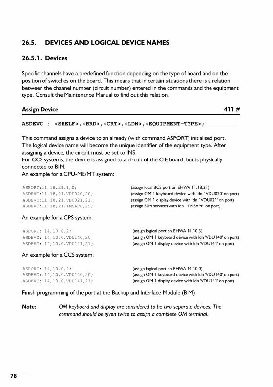
78
26.5. DEVICES AND LOGICAL DEVICE NAMES
26.5.1. Devices
Specific channels have a predefined function depending on the type of board and on the position of switches on the board. This means that in certain situations there is a relation between the channel number (circuit number) entered in the commands and the equipment type. Consult the Maintenance Manual to find out this relation.
Assign Device 411 #
ASDEVC : <SHELF>,<BRD>,<CRT>,<LDN>,<EQUIPMENT-TYPE>;
This command assigns a device to an already (with command ASPORT) initialised port.The logical device name will become the unique identifier of the equipment type. After assigning a device, the circuit must be set to INS.For CCS systems, the device is assigned to a circuit of the CIE board, but is physically connected to BIM.An example for a CPU-ME/MT system:
An example for a CPS system:
An example for a CCS system:
Finish programming of the port at the Backup and Interface Module (BIM)
Note: OM keyboard and display are considered to be two separate devices. The command should be given twice to assign a complete OM terminal.
ASPORT:11,18,21,1,0; (assign local BCS port on EHWA 11,18,21)ASDEVC:11,18,21,VDU020,20; (assign OM 1 keyboard device with ldn `VDU020' on port)ASDEVC:11,18,21,VDU021,21; (assign OM 1 display device with ldn `VDU021' on port)ASDEVC:11,18,21,TMSAPP,29; (assign SSM services with ldn `TMSAPP' on port)
ASPORT: 14,10,0,2; (assign logical port on EHWA 14,10,3)ASDEVC: 14,10,0,VDU140,20; (assign OM 1 keyboard device with ldn 'VDU140' on port)ASDEVC: 14,10,0,VDU141,21; (assign OM 1 display device with ldn 'VDU141' on port)
ASPORT: 14,10,0,2; (assign logical port on EHWA 14,10,0)ASDEVC: 14,10,0,VDU140,20; (assign OM 1 keyboard device with ldn 'VDU140' on port)ASDEVC: 14,10,0,VDU141,21; (assign OM 1 display device with ldn 'VDU141' on port)

79
Delete Device 442 #
DEDEVC : <LDN>;
It is not allowed to delete a device when it has more than one LDN assigned to it. Delete the additional LDNs with command DELDNM first.
Activate/de-activate RBU 484 #
ACTRBU : <OFF/ON>;
First an RBU (Remote Backup Unit) must be created. An RBU is used as a (remote) alternative of an LBU. This could be the case when no local backup device (e.g. SSM or SPB) is connected.The RBU is created as follows (assuming a V.24 port has been projected for remote maintenance): ASDEVC:<shelf>,<brd>,<crt>, RBUxx,26; (xx=unit)Then the RBU can be (de)activated with the ACTRBU command. The command modifies system option 68:<OFF> =0: RBU is not active: option 68 is FALSE;<ON> =1: RBU is active: option 68 is TRUE.
Display Device Characteristics 81
DICHAR : <SHELF>,[<BRD>s/r],<CRT>s/r;
Response:
SHELF: BRD: CRT: Logical Device Name: Equipmenttype:
xxxx xx xx xxxxxx xx
Prop: Gen: Rec. size: Open files: conc.comm. Baudrate:
xxxxxx xx xxxxx xxx xx xxx
- NON STORAGE CHARACTERISTICS - Virtual line length :
Cursor(up, down, left, right, home & clear)
x x x x x x
Total space (kbytes) :xxxxxx
Free space (kbytes) :xxxxxx

80
See display parameters Prop. and Gen. for more information about this response.When the EHWA of the CM module is given, all devices of that unit are displayed using the first line of the normal output only.Note that all assigned devices will be displayed. Devices assigned in `overlay' will have the same equipment type as the `original' device.
Display Device Characteristics 421
DIDEVC : <LDN>;
Response:
See appendix B for more information about display parameters Prop and Gen.Note that all assigned devices will be displayed. Devices assigned in `overlay' will have the same equipment type as the `original' device.
Assign V.24 Port 417
ASPORT : <SHELF>,<BRD>,<CRT>,<PROTOCOL-TYPE>[,<CONNECTION-TYPE>];
This command selects the required port and communication protocol for an application that wants to communicate with a device. If the BCS communication protocol is chosen, an optional parameter determines whether remote communication with modems is needed.For CCS systems: use ASPORT to assign the port number to the CIE, which physically resides on the BIM.
Change Baudrate on V.24 Port (CPU-ME/MT only) 419
CHPORT : <SHELF>,<BRD>,<CRT>s/r,<BAUDRATE>;
This command changes the baudrate for the port on the given hardware address.
LOGICAL DEVICE NAME EQUIPMENT TYPE
xxxxxx xx
SHELF BRD CRT PROP GEN REC.SIZE
OPEN FILES CONC.COMM:
xxxx xx xx xxxxxx xx xxx xx x
- NON STORAGE CHARACTERISTICS - KEYBOAR
LINE LENGTH :CURSOR
(UP, DOWN, RIGHT, LEFT, HOME, CLEAR)
xx x x x x x x

81
Delete V.24 Port 418
DEPORT : <SHELF>,<BRD>,<CRT>;
This command deletes the port characteristics that have been established by commands ASPORT and CHPORT. All devices that have been assigned on this port must be deleted first, otherwise an error is reported.For a CCS system, the last OM port can not be deleted
Display Port Characteristics 420
DIPORT : <SHELF>,<BRD>,<CRT>s/r;
Response:
The connection type is only shown if protocol type is BCS.
Change Device Application 471
CHDEVA : [<APPLICATION>[,<MINIMUM-VERSION>,<MAXIMUM-VERSION>]];
Response:
An application (like the CallManager MIS) can use this OM command to agree with the ISPBX upon the version. By this OM command, it sends it's MINIMUM-VERSION and MAXIMUM-VERSION. As a result of this, the ISPBX will set for the highest common version of the application and of the ISPBX. This OM command must be executed per session.If MINIMUM-VERSION and MAXIMUM-VERSION are omitted, the ISPBX will set for the highest version that it can support.
SHELF BRD CRT PROTOCOL TYPE CONNECTIONTYPE
BAUDRATE
xxxx xx xx x x xx
LOGICAL DEVICE NAMES
xxxxxx
xxxxxx
APPLICATION VERSION : 3

82
26.5.2. Logical Device Names
Assign Logical Device Name 61 #
ASLDNM : [<DN1>],<LDN2>[,<UNIT>];
The command ASLDNM can be used after using the ASDEVC command, to attach an additional LDN to the device on the EHWA that was assigned with ASDEVC.LDN1 must be an existing LDN and LDN2 is the LDN to assign.LDN2 cannot be `IBU' or, if journal updating is on, `CBU'.If LDN2 has the form `DONxxx' then LDN1 must have the form `VDUxxx'.If LDN is LBU resp. DBU (CCS system), the EHWA must be one of the fixed disk addresses. If DBU resp. LBU still exists, LBU resp. DBU may only be assigned if the device addresses of LBU and DBU are on the same BIM.Re-assign an LDN in the network as follows: leave LDN1 out, enter the LDN to be reassigned in LDN2 and enter the unit number where the LDN resides.
Delete Logical Device Name 62 #
DELDNM : <LDN>;
A device may have more than one LDN assigned to it. This command will not delete the last LDN. See DEDEVC to delete the last LDN.If LDN is CBU, this command must be executed when journal updating is OFF.For a CCS system, if LDN is VDU, LBU, DBU, DON or FXAL, the delete action is not allowed.
WARNING: DO NOT DELETE THE CBU, UNLESS THE CBU MUST BE MOVED!
26.6. LINKS
Assign Link 56 #
ASLINK : <SHELF>,<BRD>,<CRT>,<LINK-TYPE>;
Shelf, board and circuit refer to the switching module port, which is an SCU port in the case of a CPS system, a CSN-BC or PMC-MC-MASTER port in the case of a CPU-ME/MT system and an SNS port in the case of a CCS system.The command will ask for additional parameters, depending on the LINK-TYPE entered:
- LINK-TYPE 1, SM-CM (not for CCS systems).

83
Additional parameters:<SHELF>,<BRD>[,<CRT>];Enter the CII EHWA. The CRT parameter only has to be filled in in case of an MCI board (1), it indicates the CII function.
- LINK-TYPE 2, SM-PM controllable.
Additional parameters:<SHELF>,<BRD>,<SEQUENCE-NO>;Enter the PM EHWA and the sequence number (0 or 1 for PM2500 / 0 or 6 for PM1100).
- LINK-TYPE 3, SM-PM not controllable.
Additional parameters:<SHELF>,<BRD>,<SEQUENCE-NO>;Enter the PM EHWA and the sequence number (0 for PM2500 / 1 .. 5, 7 for PM1100).
- LINK-TYPE 4, SM-RPM controllable.
Additional parameters:<SHELF>,<BRD>;<SHELF>,<BRD>,<SEQUENCE-NO>;Enter the Local DTU EHWA, the Remote DTU EHWA and the sequence number (0 or 1 for CPS or CCS systems, and 0 only for CPU-ME/MT)
- LINK-TYPE 5, SM-RPM not controllable.
Additional parameters:<SHELF>,<BRD>;<SHELF>,<BRD>,<SEQUENCE-NO>;Enter the Local DTU EHWA, the Remote DTU EHWA and the sequence number of the link (0 .. 3).
- LINK-TYPE 6, SM-IU controllable.
Additional parameters:<SHELF>,<BRD>,<SEQUENCE-NO>,<UNIT>;Enter the DTU EHWA, the sequence number (0 or 1) and the destination unit.
- LINK-TYPE 7, SM-IU not controllable.

84
Additional parameters:<SHELF>,<BRD>,<SEQUENCE-NO>,<UNIT>;Enter the DTU EHWA, the sequence number (0 .. 7) and the destination unit.
- LINK-TYPE 8, SM-IAS controllable.
Additional parameters:<SHELF>,<BRD>,<CONTROL-SIDE>;Enter the IAS EHWA (not in R-PM) and the control side (0 or 1).
- LINK-TYPE 10, PM-PM (CPU-ME/MT only).
Additional parameters:<SHELF>,<BRD>;Enter the PMC EHWA of the opposite end.
- LINK-TYPE 11, SM-PM (CPU-ME/MT only).
Additional parameters:<SHELF>,<BRD>;Enter the PMC EHWA.Note that (in most cases) two links must be connected te a PMC-MC board.
Delete Link 57 #
DELINK : <SHELF>,<BRD>,<CRT>;
Specify the hardware address of the switching network link to be deleted. It is not possible to delete the links between the CSN and the PMC-Primary (CPU-ME/MT only).A link can only be deleted if:
- The link is in NIN;- For links to a RPM or another unit the DTU-CC should be in NIN;- The destination PMC is in NIN;- The link with the control channel may not be deleted until all not-controllable links to the
same destination have been deleted.

85
Display Link Data 58
DILINK : <SHELF>[,[<BRD>,<CRT>][,<LINK-TYPE>]];
If the board and circuit number are specified, no type of link may be entered. If board and circuit are omitted the link type may be given. If the link type is omitted all link types are displayed.Response:
EHWA LINK TYPE OFLINK
EHWA DEST EHWA LDTU EHWA RDTU SIDESEQ
UNIT
xxxxx xx xxxxxxxxxxxxxx
xxxxx xx x xxxxx xx x xxxxx xx x x x x x

86
27. HOT LINE
These commands are used to assign and delete the facility class mark Hot Line to a BSP-ID. If a BSP-ID gets this facility also the destination of the hot line is entered. There are two kinds of hot line:
- Delayed hot line. If the handset is lifted the system waits a pre-determined time before theconnection to the destination is made. This gives the user the possibility to dial anotherBSP-ID.
- Non-delayed. Immediately after the handset has been lifted the connection to thedestination is made.
Change Hot Line 122 #!
CHHOTL : <ORIG-BSP-ID>s/r[,<DEST-NUMBER>,<DELAY>, <POST-DIAL>,<TRFC>];
If only the originator BSP-ID is entered the hot line relation of the originator will be erased. Series/range can only be used when erasing.
Display Hot Line 123
DIHOTL : <ORIG-BSP-ID>s/r;
Response:
ORIGINATOR DESTINATION DELAYED POSTDIALLING TRAFFIC-CLASS
xxxxxx xxxxxxxxxxxx x x x

87
28. IABD AND LENR FACILITY
These commands are used to assign and delete the facility class mark for Individual Abbreviated Dialling (IABD) and Last External Number Repetition (LENR) to a DNR.
Assign IABD and LENR Facility 244 #!
ASIABD : <DNR>s/r;
Erase IABD and LENR Facility 245 #!
ERIABD : <DNR>s/r;
Change IABD or LENR 303 #!
CHIABD : <DNR>s/r[,[<IABD-NO>][,<DEST-NUMBER>]];
This command assigns or erases individual abbreviated numbers. The DNR must have the facility LENR/IABD assigned by ASIABD.For LENR omit the parameter <IABD-NO>. The DNR user can then call the destination number by dialling the code for LENR only.Any external number, dialled at the extension after a number has been entered by CHIABD will be overwritten.For IABD enter all parameters. The DNR user can then call the destination number by dialling the abbreviated dialling prefix followed by the number defined by IABD-NO.Erase all IABD numbers by omitting [,[<IABD-NO>][,<DEST-NUMBER>]] or erase a specific IABD number by omitting [,<DEST-NUMBER>].
Display IABD or LENR 317 #!
DIIABD : <DNR>s/r[,<IABD-NO>];
This command shows the LENR/IABD information of a DNR. If <IABD-NO> is omitted, all LENR/IABD information of a DNR is given.Response:

88
DNR IABD-NO DEST
2400 -- 0030740000
2400 00 0030740001
2400 01 0030740002
2400 90 0030740003

89
29. IBSC - BSPT RELATIONS
Create BSPT Definition 78 #!
CRBSPT : <BSPT>;
Additional parameter: [<IBSC>];The BSPT to be entered in this command ranges from 20…93.Enter all IBSCs belonging to the BSPT. Exit with a single semicolon on a line.The second line maintenance manual describes how to change a BSPT, which is created by this OM command.
Display BSPT Definition 79
DIBSPT : <BSPT>s/r;
For each BSPT the list of IBSCs contained are given:Response:
BSPT IBSC
xxx xxxxxxxxxxx
xxx xxxxxxxxxxx

90
30. INITIALISE DISK
This command is used to format the back-up device.
Initialise Disk 289
INIDSK : <LDN>[,<VOLUME>];
This command will occupy the VDU until the back-up device is formatted, which could take a considerable time. It is therefore advised to execute this command from a command file.If the logical device (LDN) is the Internal Back-up Unit (IBU), the parameter VOLUME must be omitted. In this case the command execution will take about 90 seconds.Response:
WARNING: IF THE LDN = IBU THEN THE CONTENTS OF THE BACK-UP DEVICE (HARD DISK OR SOLID STATE BACK-UP OR FEPROM ON CPU-ME/MT) WILL BE LOST!
Password:

91
31. INTEGRATED ANNOUNCEMENT SYSTEM
If an Integrated Announcement Server (IAS) is connected to the unit, an announcement can be given to incoming calls.
Change Announcement Information 318 #!
CHANNO : <ANN-SELECTION>[,[<ANN-NO>]];
If [,[<ANN-NO>]] is omitted, the announcement message is removed.For ANN-SELECTION 6: omit [<ANN-NO>] if only dynamic announcements are needed.The command will ask for additional parameters:
- ANN-SELECTION is 0: DDI fail calls
Enter assistance group number: [<ASSIST-GROUP>];Enter encountered DDI fail situation: [<ANN-DDI-FAIL>];
- ANN-SELECTION is 1: Successful DDI calls
Enter assistance group number: [<ASSIST-GROUP>];
- ANN-SELECTION is 2: Non-DDI calls(includes PLE, INE, MCNE, SCNE and CANS)
Enter assistance group number: [<ASSIST-GROUP>];
- ANN-SELECTION is 3: Calls to operator A-queue
Enter assistance group number: [<ASSIST-GROUP>];Enter A-queue: [<A-QUEUE>];
- ANN-SELECTION is 4: Station calls for ACD group
Enter ACD group DNR: [<GROUP-DNR>];Enter `First announcement delay time': <ACD-TIME-PERIOD>;
- ANN-SELECTION is 5: Night announcement for ACD group
Enter ACD group DNR: [<GROUP-DNR>];

92
Enter `First announcement delay time': <ACD-TIME-PERIOD>;
- ANN-SELECTION is 6: Delay message for ACD group
Enter ACD group DNR: [<GROUP-DNR>];Enter `Delay message pre-time': <ACD-TIME-PERIOD>;Enter `Delay message repeat-time': <ACD-TIME-PERIOD>;Enter `ANN-NO for QUEUE POSITION i': <ANN-NO>;(This is asked up to 16 times)
- ANN-SELECTION is 7: Music On Hold
Display Announcement Information 392
DIANNO : <SELECT-ANNOUNCEMENT-DATA>;
Depending on the selection made, the system will ask for additional parameters:
- In case of an assistance group:
Enter assistance group number: [<ASSIST-GROUP>];Response:
- In case of an ACD group:
Enter ACD group DNR: <GROUP-DNR>;Response:
DDI-FAIL: BUSY DIAL-TIME-OUT NBR-UNOBT OTHER-FAIL DDI-SUCC
NON-DDI
xx xx xx xx xx xx
A-QUEUES: A1 A2 A3 A4 A5 A6 A7 A8 A9 A10 A11A12
A13A14
A15A16
x x x x x x x x x x x x x x x x
STATION CALLS: ANN-NO PRE-TIME
xx xx
NIGHT ANNOUNCEMENT: ANN-NO PRE-TIME
xx xx
DELAY MESSAGE: ANN-NO PRE-TIME
REPEAT-TIME
xx xx xx

93
- In case of Music On Hold:
QUEUE-POS ANN-NO
x xx
MUSIC ON HOLD: ANN-NO
XX

94
32. INTER UNIT ROUTING (iS3070/3090 only)
Change Route Relation 271 #
CHRORE : <UNIT>,<ROUTE-ALTERN>;
The command asks for additional parameters:[<ORIG-UNIT>,<FAR-DEST>[,<IU-ROUTE>]];
If the inter unit route number is omitted the route relation is erased. If all additional parameters are omitted the command is stopped. If the alternate route is entered as routing alternative the originator unit must equal the unit in which the route relation must be changed.
Change Unit Relation 272 #
CHUNRE : <UNIT>,<ROUTE-ALTERN>;
The command asks for additional unit parameters:[<ORIG-UNIT>,<FAR-DEST>[,<NEAR-DEST>]];
If the near destination is omitted the unit relation is erased. If all additional parameters are omitted the command is stopped. If the alternate route is entered as routing alternative, the originator unit must equal the unit in which the route relation must be changed.
Display Unit and Route Relations 273
DIURRE : <UNIT>,<ROUTE-ALTERN>,<ORIG-UNIT>s/r;
Response:
ROUTING ORIGINATOR FAR NEAR INTERUNIT
ALTERNATIVE UNIT DESTINATION DESTINATION ROUTE
xxx xxx xxx xxx xxx

95
33. INTER UNIT TRUNK TRAFFIC
Note: Inter unit networking is only available on iS3070 and iS3090 systems.
Assign Bundle to Interunit Route 265 #!
ASIBND : <BUNDLE>,<ROUTE>,<UNIT>;
Assign Line to Interunit Bundle 267 #!
ASILIN : <SHELF>,<BRD>,<CRT>,<BUNDLE>;
Change Inter Unit Bundle Characteristics 264 #!
CHIBNC : <BUNDLE>,<BUNDLE-DIR>,<UNIT>;
Delete Bundle from Inter Unit Route 266 #!
DEIBND : <BUNDLE>,<UNIT>;
Delete Line from Inter Unit Bundle 268 #!
DEILIN : <SHELF>,<BRD>,<CRT>;
Display Inter Unit Bundle Data 270
DIIBND : <BUNDLE>,<UNIT>;
Response:

96
Display Inter Unit Route Data 269
DIIROU : <ROUTE>,<UNIT>;
Response:
BUNDLE ROUTE UNIT DIR
xx xx xx x
SEQ SHELF BRD CRT
xx xxxxx xx xx
ROUTE UNIT SEQ BUNDLE DIR
xx xx xx xx xx

97
34. LICENSES
With this command one can display the following information about active licenses:
- License number and name;- License granted yes or no;- Total number of possible licensed items;- Total number of used items (licensed and not licensed);- Not licensed BSP-IDs (when exists);- Not licensed ACD-agents (when exists)- Not licensed SOPHO iSLinks for CSTA (when exists);- Not licensed CSTA monitors (when exists).- Not licensed desksharing BSP-ID (when exists).
Display actual License Information and not licensed Items 462
DILICS : [<LICENSE-NUMBER>][,<UNIT>];
If LICENSE-NUMBER is omitted, every licenses number is displayed.If UNIT is omitted, then the licenses of all units are displayed.Response:
UNIT NR DESCRIPTION GRANTED
TOTAL USED
02 001 : BSP-IDs Yes 3200 3204
NOT LICENSED DNR-BSPT
2472-95
2473-95
2474-95
2475-95
UNIT NR DESCRIPTION GRANTED
TOTAL USED
02 002 : IMP Yes - -
02 003 : ACD agents Yes 0112 0004
02 004 : ISDN trunk Yes - -
02 005 : DPNSS Yes - -
02 006 : Cost accounting Yes - -
02 007 : System management Yes - -
02 008 : FDCR Yes - -

98
02 009 : LCCR Yes - -
02 010 : Voice Mail Interf. Yes - -
02 011 : iSNet PVN No - -
02 012 : IPD No - -
02 013 : MOH from IAS No - -
02 014 : Dynamic delay msg. No - -
02 015 : Oper. monitoring No - -
02 016 : Service license No - -
02 017 : S0-bus Links CSTA Yes 0004 0001
02 018 : Act. CSTA monitors Yes 0032 0034
NOT LICENSED DNR-BSPT
2800-95
2801-95
02 019 : Deskshar. BSP-ID Yes 0100 0080
02 020 : CNND Yes - -
02 021 : Ethernet link CSTA Yes 02 02
02 023 : CSTA IO services Yes
02 024 : CSTA IO registrat. Yes 02 02
02 025 : Free Numbering Yes

99
35. LOAD CONTROL
The load of a unit can be expressed in “permission units” of the CPU. The value of the permission units approaches the real load in %, but in case of changing load characteristics they may deviate. They should be interpreted as relative values. This load is caused by tasks running at the same moment. Examples of tasks are: calls, periodic tests and OM commands. These tasks are distributed over sources. A source combines a specific category of tasks. There are two types of sources. The primary sources show tasks that can be directly identified. The secondary sources contain tasks that are started by other tasks. For each source and for the unit as a whole, a guaranteed load level exists. If the actual load of a unit is above its guaranteed level, it will only allow more tasks as long as they stay below the guaranteed level of the corresponding source.The monitor process and the display command are completely independent of each other.
35.1. MONITOR LOAD
The load in a unit can be monitored. This process writes information about the load in all the sources to a file. Only one load monitoring process can run in a unit.
Start Load Monitor 298
STALDM : <FILE>,<MONITOR-INTERVAL>,<ON-TIME>,<OFF-TIME>,<DATA-INDICATOR>[,<UNIT>];
The layout of the output is the same as in the DIOVLD command, but in addition a 13th column indicates the actual load percentage and each line is preceded by the date and time in the following format:YYYY-MM-DD +W+ HH:MM
Cancel Load Monitor 299
CANLDM : [<ON-TIME>],[<OFF-TIME>][,<UNIT>];
If the load monitor was active, it will be stopped and the file will be closed.
Display Load Monitor 346
DISLDM : [<UNIT>];
Response:

100
35.2. DISPLAY LOAD
Display Overview of Load 297
DIOVLD : <DATA-INDICATOR>[,<UNIT>];
Response:
Primary sources are:
Secondary sources are:
UNIT ON-TIME
OFF-TIME
ON-TIME
OFF-TIME
EXPIRED
EXPIRED
xx xxxxx xxxxx xxxxx xxxxx
SAS SAS SAS OM OM OM CP CP SAS OM GOS UNIT
URG FHL TST URG MNT MAT CAL RM GEN GEN RM TOT
xx xx xx xx xx xx xx xx xx xx xx xx
SAS-URG System Assurance urgent actionsSAS-FHL System Assurance fault handling and locationSAS-TST System Assurance preventive testsOM-URG Operational Maintenance urgent commandsOM-MNT Operational MaintenanceOM-MAT Operational Maintenance testsCP-CAL Call ProcessingCP-RM Call Processing Registration and Measurements
SAS-GEN System Assurance workOM-GEN Operational Maintenance workGOS-RM Global Operating System resource managementUNIT-TOT indicates the total load for the unit.

101
36. MANAGER DATA
36.1. SYSTEM MANAGER DATA
Display Manager Data 221
DIMDAT : <MANAGER-TYPE>[,[<MANAGER-INDEX>s/r] [,<UNIT>]];
This command can show the parameter value(s) of either boundaries, options or timers.The Second Line Maintenance manual gives detailed information of the items mentioned above.If the index is omitted all data of the specified manager is displayed.Response:
36.2. MFC MANAGER DATA AND SUBSCRIBER CATEGORY
Display MFC Manager Data 222
DIMMFC : <MFC-TYPE>,<MFC-INDEX>s/r,[<MFC-ADD-INDEX>s/r][,<UNIT>];
Response:
Change Subscriber Category of DNR/BSP 72 #!
CHCASC : <SUBSCR-CAT>,<BSP-ID>s/r;
The Subscriber Category is transmitted during each outgoing MFC call as first digit of the Calling Line Identity (CLI).
UNIT MANAGER-TYPE MANAGER-INDEX VALUE (TIME-UNIT)
xx xx xx xx xx
MFC-TYPE MFC-INDEX MEANING-MFC-SIGNAL or
MFC-TYPE MFC-INDEX BACKWARD-MFC-SIGNAL CALL-CONTROL-ACTION or
MFC-TYPE MFC-INDEX MFC-ADD-INDEX BACK-MFC-SIGNAL CALL-CONTROL-ACTION or
MFC-TYPE MFC-INDEX CALL-CONTROL-ACTION or
MFC-TYPE MFC-INDEX MFC-ADD-INDEX CALL-CONTROL-ACTION

102
This command assigns a Subscriber Category to a BSP-ID. This applies to both extensions and operators. A Subscriber Category assigned to an operator position must be effectuated by a transition from day to night of the operator position.
Display Subscriber Category of DNR/BSP 71
DICASC : <BSP-ID>s/r;
Response:
DNR-BSPT SUBSCR-CAT
xxxX xx

103
37. MERCURY INDIRECT SERVICE
This OM command for Smart Box Emulation is used to change the authorization code (PIN code) for each user group in the system. This PIN code is used by Mercury for Call authorization.
Change Authorization Code 401
CHAUCO : [<CV>];
If the CV (Compatibility Value) is omitted the default value is used (usually 0).Response:
Old authorizationcode :
<AC>;
New authorization : <AC>;
Verification : <AC>;

104
38. MISCELLANEOUS DNR ACTIONS
For maintenance on the internal database two OM commands are available to be used by either the MAC-manager or through standard OM. The commands below concern the DNR/name relations.
Change DNR/Name Relation 121 #!
CHNAME : [<DNR>s/r];
This command deletes or assigns the name related to the DNR.When the DNR is omitted, the system will ask for additional parameters:Enter [<DNR>[,<NAME>]];
The question is repeated until a semicolon (;) is entered. If NAME is omitted the relation is deleted.Names may be entered in upper and/or lower case characters.
Note:- The size of the database can be projected smaller than the maximum number
of DNRs in the unit. This implies that congestion can occur on storing a new name into the database, when the database is full.
- A name/DNR relation is automatically stored in the unit the DNR is assigned in. Therefore it is not possible to move a name/DNR relation to another unit, unless the DNR is moved to the other unit.
- It is advised to enter names, by first entering the last name of a person and then the first names or first name initials. This is in line with the normal browsing functions.
Display DNR/name Relation 339
DINAME : <DNR>s/r;
This command shows the name that is assigned to the DNR.

105
39. MULTIPLE SUBSCRIBER NUMBER
Change Fixed MSN Digit 431 #!
CHFMSN : <BSP-ID>,<DIGIT>;
Change MSN Parameters 415 #!
CHMSNP : <SHELF>,<BRD>,<CRT>s/r,<MSN-TYPE> [,<NO-MSN-DIGITS>];
Parameter NO-MSN-DIGITS can only be entered if MSN-TYPE indicates MSN (1).
Note: When associated hardware addresses (i.e. the two EHWAs of an S0 bus) are involved, then the MSN parameters of both hardware addresses must be projected identical.
Display Fixed MSN Digit 441
DIFMSN : <BSP-ID>s/r;
Response:
Display MSN Parameters 424
DIMSNP : <SHELF>,<BRD>,<CRT>s/r,;
Response:
FIXED MSN
DNR-BSPT DIGIT
xxx xxx
SHELF BRD CRT MSN-TYPE NUMBER-OF-MSN-DIGITS
xxxx xx xx x x

106
40. NIGHT TRAFFIC AND SPECIAL EXTENSIONS
40.1. CANS AND HOOTER
Assign Unit to CANS Area 203 #!
ASCANS : [<UNIT-1>s/r,<UNIT-2>];
<UNIT-1> will be assigned to the Common Answering Night Service (CANS) area in <UNIT-2>. In a single unit system both parameter 1 and 2 can be omitted.
Change Hooter Presence Mark 205 #!
CHHOOT : <MARK>[,<UNIT>s/r];
Indicates to the system if a hooter is present or not.
Display CANS and Hooter Characteristics 206
DICANS : [<UNIT>];
If no unit number is specified the command is performed system wide.Response:
Erase Unit from CANS Area 204 #!
ERCANS : [<UNIT-1>s/r,<UNIT-2>];
Unit 1 will be erased from the CANS area in unit 2. In a single unit system both parameter 1 and 2 can be omitted.
40.2. NIGHT EXTENSIONS
To display night extensions the DISPEX command is used; see next section.
UNIT HOOTER NIGHT TRAFFIC CLASSES CANS AREA
INE SCNE MCNE CANS
xx xxx xx xx xx xx xxxxxxx

107
Change Individual Night Extension 198 #!
CHINEX : <SHELF>,<BRD>s/r,<CRT>s/r[,[<B-CHANNEL>s/r][,<DNR>]];
When the DNR parameter is omitted the Individual Night Extension (INE) is deleted. The B-Channel only has to be given in case of an ISDN trunk line.
Change Main Common Night Extension 196 #!
CHMCNE : [<UNIT>s/r][,<DNR>][,<ASSIST-GROUP>];
It makes it possible to assign or to change a specific Main Common Night Extension (MCNE). If the DNR is omitted in the command, the specific MCNE is deleted.ASSIST-GROUP has been added to the command as from SSW 805.28. If ASSIST-GROUP is omitted a general MCNE is assigned. If DNR and ASSIST-GROUP are omitted, the general MCNE is deleted.
Change Sub Common Night Extension 197 #!
CHSCNE : <ROUTE>s/r[,<DNR>];
When the DNR is omitted the Sub Common Night Extension (SCNE) is deleted.
Change Traffic Class of Night Extension Group 201 #!
CHTRNE : <NE-LEVEL>,<TRFC>[,<UNIT>s/r];
40.3. SPECIAL EXTENSIONS
Change Overflow Extension 200 #!
CHOVEX : <ROUTE>s/r[,<DNR>];
When the DNR is omitted the Overflow Extension (OVE) is deleted.

108
Change Permanent Line Extension 199 #!
CHPLEX : <SHELF>,<BRD>s/r,<CRT>s/r[,[<B-CHANNEL>s/r][,<DNR>]];
When the DNR is omitted the Permanent Line Extension (PLE) is deleted. The B-Channel only has to be given in case of an ISDN trunk line.
Display Special Extensions 202
DISPEX : [<UNIT>];
The unit number is only displayed for the MCNE DNR in a multi unit system. The assistance group is only displayed for an (assistance group) specific MCNE.The route number is only displayed for the SCNE or OVE DNR. The EHWA (SHELF, BRD, CRT) and the B-channel are only displayed for the INE or PLE DNR.Response:
TYPE DNR UNIT ROUTE SHELF BRD CRT B-CH ASSISTANCE-GROUP
xx xxxxxx xx xx xxxxx xx xx - xx

109
41. NUMBERING SCHEME
The whole numbering scheme can be divided into the internal numbering scheme and the external numbering scheme. Both types of number analysis data are held in the same type of trees. As the internal and external numbering scheme data require different parameters, different OM commands are available. Some commands are valid for both numbering schemes.The names internal number and internal numbering scheme can give confusion of thought. Internal numbers are the numbers that belong to extensions (DNRs). Such an internal number is only one of the analysis results of the internal numbering scheme. Other analysis results in the internal numbering scheme are abbreviated number, follow-me prefix etc.
41.1. NUMBERING SCHEME GENERAL
Change Traffic Class Barring 38 #!
CHTBAR : <TREE>,<NUMBER>,<TRFC>;
This command is used to change the traffic class in a number analysis tree, without affecting the analysed digits.
Display Number Analysis Result String 426
DINARS : <TREE>s/r[,<RESULT-ID>];
This command searches for the number that is related to a result identity. When Result-Id is omitted, all related numbers in the given tree will be displayed.Response:
*) As from SSW 805.26 the ̀ ID NUMBER' has been added to the response (when applicable). It gives information about the destination (assigned with ASINTN or CHCSDD). The destination `ID' is given and the related `NUMBER'.Example:The `ID NUMBER' could be:
TREE CODE ANALYSIS RESULTNUMBER ID NUMBER *)
xx xxx xxxxxxxxxxxxxxxxxx xxxxx xxxx
P 1 meaning: Paging route 1D 123 meaning: Destination number 123

110
Display Number Analysis Scheme Data 42
DINASD : <TREE>s/r[,<NUMBER>];
This command is used to display (part of) the contents of a number analysis tree. If an existing NUMBER is entered the display starts from the last pyramid in which this digit string is analysed.The tree numbers for the internal numbering scheme can be displayed by using command DIDIAL, for DDI (or DPNSS-in) by using command DIROUT and for DDO (or DPNSS-out) by using command DIDEST. The tables of the tree are displayed per level. Each table consists of:A B C D E F G H I J K L M N O P
These letters have the following meaning:
Display Number Analysis Scheme Used Memory 45
DINASM : ;
Response:
Q 5 meaning: A-queue number 5U 2 meaning: Unit 2
A Digit in tableB Result ID numberC Analysis resultD Next analysis tableE Number length / PVN ModeF Destination number / route table / A-queue/Valid. type (≥ 28) / σερϖερ (≥ 30)G Paging route numberH Traffic Class (TRFC)I Minimum number lengthJ Maximum number lengthK Dial tone placeL Pre-digitM Post-digitN Restoration modeO Toll operator intrusion allowance/toll-free number (≥ 25)P Barring possible mark
ANALYSIS TABLES EXTERNAL NUMBERBLOCKS
(PROJECTED) (FREE) (MAXIMUM) (FREE)
xx xx xx xx

111
Make Number Unobtainable 39 #!
MAKENU : <TREE>,<NUMBER>;
This command is used to erase an internal or external numbering scheme number or block.
41.2. INTERNAL NUMBERING SCHEME
Assign Analysis Tree to Dial Type 33 #!
ASTREE : <TREE>,<DIAL-TYPE>s[,<AG>];
The analysis group is only used for dial types “extension dialling” and “enquiry dialling”. If it is omitted the default will be used.
Assign Internal Numbering Scheme Block 34 #!
ASBLCK : <TREE>,<NUMBER>,<TRFC>,<NUMBER-LENGTH>, <RESULT-ID>;
This command is used to assign a block of internal numbers or abbreviated dialling. Only the RESULT-IDs 10, 23 and 24 are allowed.
Assign Internal Numbering Scheme Number 36 #!
ASINTN : <TREE>,<NUMBER>,<TRFC>,<RESULT-ID>[,[<DEST/NUMBER>][,<NUMBER-LENGTH>]];
This command is used to assign a prefix. In this command the parameters DEST/NUMBER and NUMBER-LENGTH must be omitted. Exceptions to this rule are:
- If RESULT-ID = 49:DEST/NUMBER must be given. Fill in the A-queue number (1..16).
- If RESULT-ID = 14, 21, 91, 92, 138DEST/NUMBER must be the destination number.
- If RESULT-ID = 12, 13, 120…125, 139…142DEST/NUMBER must be the paging route number.
- If RESULT-ID = 20, 25, 43, 68, 69, 70, 71, 72, 73, 74, 82, 105, 106, 107, 108,109, 110, 111, 112, 113, 114, 115, 118, 119, 127, 135, 136:NUMBER-LENGTH must be given and DEST/NUMBER must be empty.

112
Note: The NUMBER-LENGTH in RESULT-ID 111 is used to validate the dialled cost centre code. The last digit of the cost centre code must be equal to the sum of the other digits MOD length. E.g. if the length is 6 then 1 2 3 4 5 3 is a valid cost centre code. 1+2+3+4+5=15. 15 MOD 6 =3 (remainder after division).Last digit is also 3, therefore it is a valid cost centre code.
- If the RESULT-ID is 50, 51, 143 and 144 and the DEST/NUMBER is empty or '0', PIDvalidation (SSM) is used. If the DEST/NUMBER = 1 then password (IPD) validation is used.The NR-LENGTH (0…16) is the length of the PID or password and NUMBER means'prefix'.
- If RESULT-ID = 82: The number of characters in NUMBER must be compatible with theTMS digit position.
- If RESULT-ID = 104: NUMBER-LENGTH (0…16) indicates length of password;DEST/NUMBER is 0 means `change password of current DNR' and 1 means `changepassword of any other DNR'.
- If RESULT-ID = 132, 133: Enter the unit number for DEST/NUMBER. NUMBER-LENGTH must be empty in the case of 132. In the case of 133, NUMBER-LENGTH mustbe PVN mode.
- RESULT-IDs 10, 22, 23, 24 and 145 are not allowed.
Change CSTA Server Dialled Data 158 #!
CHCSDD : <TREE>,<NUMBER>,<TRFC>,<SERVER-AND-ACTION-CODE>[,[<PW-NBR-LENGTH>][,<ADD-INFO-NBR-LENGTH>]];
With this command a prefix can be defined leading to the result-id “CSTA server dialled”.
Display CSTA Server Dialled Data 215
DICSDD : <TREE>[,[<NUMBER>][,<SERVER-AND-ACTION-CODE>]];
This command displays the data stored of the prefixes with result-id “CSTA server dialled”.If the parameter NUMBER is omitted, all available CSTA server dialled data for the given TREE and SERVER-AND-ACTION-CODE will be displayed.If the parameter SERVER-AND-ACTION-CODE is omitted, all available CSTA server dialled data for the given TREE and NUMBER will be displayed.If the parameter NUMBER and SERVER-AND-ACTION-CODE are omitted, all available CSTA server dialled data for the given TREE will be displayed.The layout of the display is as follows (example):

113
Display Dial Type Relations 44
DIDIAL : [<DIAL-TYPE>s/r];
If DIAL-TYPE is omitted all dial types will be displayed. Response:
41.3. EXTERNAL NUMBERING SCHEME
Assign External Numbering Scheme Number 37 #!
ASEXTN : <TREE>,<NUMBER>,<TRFC>,<MIN-LENGTH>,<MAX-LENGTH>,<DIALTONE-PLACE>;
Additional parameter: [<ROUTE-TABLE>];The number (or number range) gets result-ID 022 (External number).ROUTE-TABLE is only relevant for Least Cost Call Routing.
TREE NUMBER SERVER-CODE ACTION-CODE #PASSWORD-DIGITS #ADD.INFO-DIGITS
0 #49 1 5 0 4
0 #49 1 5 0 4
0 #49 1 5 0 4
0 #49 1 5 0 4
DIAL-TYPE ANALYSIS GROUP No ANALYSIS TREENo
0: Extension dialling xx xx
1: Enquiry dialling xx xx
2: Operator dialling xx
3: Post dialling xx
4: Alternative destinationdialling
xx
5: FM primary dialling xx
6: Pick up destinationdialling
xx
7: Executive secretarydialling
xx
8: Overlay time out dialling xx xx
9: Overlay continue dialling xx xx

114
Assign External Numbering Scheme Number with additional Parameters 328 #!
ASEXTP : <TREE>,<NUMBER>,<TRFC>,<MIN-LENGTH>,<MAX-LENGTH>,<DIALTONE-PLACE>;
Additional parameters:[<PRE-DIGIT>][,<POST-DIGIT>][,[<REST-MODE>][,[<INTR-ALL/CHARGED>]]],<ROUTE-TABLE>;This command is used when the number sent to the opposite exchange must be preceded by a pre-digit (also called Class-of-Call or Call-type) or followed by a post-digit and/or when the restoration mode and/or the intrusion allowance (toll-free, ISDN) are used (CSS1). The number (or number range) gets result-ID 022 (External number).
Assign Barred External Number 40 #!
ASBARR : <TREE>,<NUMBER>;
This command is used to bar an external number. The external number must have been defined with ASEXTN. This means that the result-ID 022 (External number) must be present in the concerning tree. Use DIDEST to locate the right tree number. In this command <NUMBER> can be 1 … 16 digits.
Erase Barred External Numbers 41 #!
ERBARR : ;
All numbers in the barring list will be erased from it.
Display Barred External Numbers 43
DIBARR : ;
Response is a list of barred external numbers and the analysis tree number.
--BARRED NUMBER-- ANALYSIS TREENo
xxxxxxxx xx

115
42. OPERATOR CONSOLE
42.1. B-BUTTON / ACCESS CODE RELATION
CHBBUT and DIBBUT are provided to read and write the relation between B-buttons and trunk access codes. After a command which modifies this relation has been executed, the other B-button bound data (routes associated with the access code, B-LED status) are updated by the system. The relation is defined per unit.
Change or Delete Trunk Access Code of B-button 184 #!
CHBBUT : <B-BUTTON>[,<TRUNK-CODE>] [,<UNIT>s/r];
If the trunk access code is omitted, the code under the indicated B button will be deleted.
Display Trunk Access Code of B-button 185
DIBBUT : <B-BUTTON> [,<UNIT>s/r];
Response:
42.2. QUEUE PREFERENCE
CHMQPR, CHCQPR, CHAQPR modify the answering priority list for the M, C and A call types. DIAQPR, DICQPR and DIMQPR display the list for A, C and M call types.The commands which change the answering priority for M and C call types affect the preference for both the general and individual call queues, the M and C queue preference lists are the same for all operators in one unit.The commands for A queues change the priority order in which incoming calls are served by a specific operator. In case of incoming calls (A calls) there is a preference table for every operator.
B-BUTOON UNIT TRUNK-CODE
xx xx xx

116
42.2.1. A-Queue
Change Answering Priority of A-Queue 188 #!
CHAQPR : <OPERATOR-DNR>, <A1>[,<A2>[,<A3>[,<A4>[,<A5>]]]];
If from a certain An (n=1 to 5) parameter onwards the rest of the parameters are omitted, the preference list will be set to the default order, with the exception of the values already entered. The default order is 1 to 16 (see parameter An).If A5 has been entered, the following request appears:<Enter call types [<A6> [,<A7> … <A13>]]] …]:
Display Answering Priority of A-Queue 189
DIAQPR : <OPERATOR-DNR>s;
Response:
42.2.2. C-Queue
Change Answering Priority of C-Queue 187 #!
CHCQPR : [<UNIT>s/r],<C1>[,<C2>[,<C3>[,<C4>[,<C5>]]]];
If from a certain Cn (n=1 to 5) parameter onwards the rest of the parameters are omitted, the preference list will be set to the default order, with the exception of the values already entered. The default order is:
If C5 has been entered, the following request appears:
OPERATOR
A-QUEUE PRIORITY LIST (Descendingorder)
xxxxxx x x x x x x x x x x x x x x x x
(3) - Recall - on hook(2) - Recall - not on hook(0) - Direct dial in - not answered(1) - Direct dial in - unsuccessful(5) - Taxmetering(6) - Through connection - busy(8) - Through connection - ringing(7) - Preferred call(4) - Series

117
<Please enter additional call types [<C6> [,<C7> [,<C8> [,<C9>]]]];
Display Answering Priority of C-Queue 361
DICQPR : [<OPERATOR-DNR>s][,<UNIT>s/r];
One or both parameters must be omitted. If both parameters are omitted, the answering priority is displayed for all operators in all units of the system.Response:
42.2.3. M-Queue
Change Answering Priority of M-Queue 186 #!
CHMQPR : [<UNIT>s/r],<M1>[,<M2>[,<M3>]];
If both M2 and M3 are omitted, the preference list will be set to the default, with the only exception of M1 as first element (and the former default first element in the default position of M1). The default order is: preferred call (2), normal call (1), individual call (0).
Display Answering Priority of M-Queue 362
DIMQPR : [<OPERATOR-DNR>s][,<UNIT>s/r];
Response:
42.2.4. Queue to Lamp Relation
Change Queue Lamp Relation 423 #!
CHQLMR : <LAMP-ID>,<INTERNAL-CALL-TYPE/A-QUEUE-NUMBER>[,<UNIT>];
If UNIT is omitted the command will be executed system wide.
OPERATOR-DNR UNIT CODE CALL-TYPE
xxxx x x xxxxxxxxxxxx
OPERATOR-DNR UNIT CODE CALL-TYPE
xx xx x XXXXXX

118
Display Queue Lamp Relation 422
DIQLMR : [<LAMP-ID>] [,<UNIT>s/r];
If LAMP-ID is omitted, all LAMP-IDs are displayed. If UNIT is omitted the command will be executed system wide.Response:
42.3. OPERATOR AVAILABILITY LIST AND ASSISTANCE GROUP
CHOPAV and DIOPAV are used to determine and read the order in which the units have to be hunted for operator service when a unit does not offer operator service to the calls originated in it. This sequence is defined per unit and per assistance group.
42.3.1. Availability List
Change Operator Availability List 190 #!
CHOPAV : <UNIT>[, [<ASSIST-GROUP>] [,<U1>[,<U2>[,<U3>[,<U4>]]]]];
If from a certain Un (n=1 to 5) parameter on all parameters are omitted the availability list will be initialized only with the entered Un-1 units data.If U4 has been entered, the following request appears:<Enter none to 9 additional unit numbers [<U5> [,<U6> … [,<U13 ] … ] ];
Display Operator Availability List 191
DIOPAV : [<UNIT>s/r][,<ASSIST-GROUP>];
If the unit number is omitted the command is performed system wide. Unit numbers in the availability list are displayed in descending order of priority.The display format is:
UNIT LAMP QUEUE LIST
xx xx xx
UNIT Assist-group Availability list (Descendingorder)
xx xx xx

119
42.3.2. Assistance Group
CHASOP, DIASOP, CHASCV and DIASCV define and read the relation between assistance groups and operators and between assistance groups and CV values. The purpose is to split up the system for multi user operation.
Change Assistance Group of Compatibility Value 194 #!
CHASCV : <CV>s/r[,<ASSIST-GROUP>];
Change Assistance Group of Operator 192 #!
CHASOP : <OPERATOR-DNR>s[,<ASSIST-GROUP>];
If the assistance group is omitted the general assistance group will be taken. The operator must have inactive status: Headset removed (i.e. night mode) or global status OUT or NIN.
Display Assistance Group of Operator 193
DIASOP : <OPERATOR-DNR>s;
If no assistance group is displayed the operator is assigned to the general assistance group.Response:
Display Assistance Group of Compatibility Value 195
DIASCV : <CV>s/r;
If no assistance group is displayed the general assistance group is related to this compatibility value.Response:
OPERATOR ASSISTANCE-GROUP
xxxx xx
CV ASSISTANCEGROUP
xx xx
120
Display Service Mode of Assistance Groups 366
DISEMD : [<ASSIST-GROUP>s/r];
The service mode indicates the DAY or NIGHT condition of the operators. If the assistance group is omitted the general assistance group is displayed.Response:
Change Assistance Group Properties 476 #!
CHASPR : [<ASSIST-GROUP>],<ASSIST-GROUP-PROPS> [,<UNIT>];
This command can switch operator monitoring ON or off. If it is switched on, the command will ask for an additional parameter:Enter 'Operator monitoring logical device name' (LDN) : <LDN>
If you type ' ; ' the LDN is not changed.When ASSIST-GROUP is omitted, the general assistance group is changed.
Display Assistance Group Properties 477
DIASPR : [<ASSIST-GROUP>][,<UNIT>];
Response:
42.4. OPERATOR STATUS
The commands in this group are used to inform the chief operator about the condition of all operator consoles.
ASSIST-GROUP SERVICE MODE
xx xxxx
UNIT ASSIST-GROUP PROPERTIES MIS-LDN
xx xx x xxx

121
Display Activity and Status of Operators 365
DIOPST : [<OPERATOR-DNR>s][,<UNIT>s/r];
This gives information about the activity (active or not active) and about the state (idle, busy, OM mode). One or both parameters must be omitted. If both parameters are omitted the status of all operators in the system is displayed.Response:
Display List of Active Operators 363
DIOPAC : [<ASSIST-GROUP>s/r][,<UNIT>s/r];
If UNIT is omitted, all operators in the system are displayed. If the assistance group is omitted, the general assistance group is displayed.Response:
Display List of Idle Operators 364
DIOPID : [<ASSIST-GROUP>s/r][,<UNIT>s/r];
If UNIT is omitted, all operators in the system are displayed. If the assistance group is omitted, the general assistance group is displayed.Response:
Display Load of Operators 367
DIOPLD : [<OPERATOR-DNR>s][,<UNIT>s/r];
One or both parameters must be omitted. If both parameters are omitted the status of all operators in the system is displayed.Response:
OPERATOR-DNR UNIT ASSIST-GROUP ACTIVITY
STATUS
xxxx xx xx xxx xxx
OPERATOR-DNR UNIT ASSIST-GROUP
xxxx xx xx
OPERATOR-DNR UNIT ASSIST-GROUP
xxxx xx xx
122
Display Load and Status of Operators Continuously 343
DIOPCT : [<OPERATOR-DNR>][,<UNIT>];
One or both parameters must be omitted. If both parameters are omitted data about the unit where the OM terminal is located will be displayed. The displayed information is refreshed periodically, with a default of 15 seconds.Response:
C indicates the number of calls waiting;L indicates the first or second overload:
DNR UNIT A:L C A1:L C A2:L C A3:L C C:L C M:L C TOTAL
xxxx xx x x x x x x x x x x x x xx
DNR ACTIVITY
STATUS A:C L A1:C L A2:C L A3:C L C:C L M:C L M2:C L TOTAL
xxxx xx xx x x x x x x x x x x x x x x xx
L=1 First overload level. The call is waiting and all operators are busy.L=2 Second overload level. The call is waiting for more than 20-40 seconds, or more calls are
waiting.

123
43. OVERLAY MODULES
Delete Specified Overlay Module from Memory 86 #
DEOVLM : <OVERLAY-ID>s[,<UNIT>s/r];
Display Overlay Modules in Memory 87
DIOVLM : [<OVERLAY-ID>s][,<UNIT>s/r];
If the overlay identity is omitted, all overlays are displayed.Response:
Load Overlay Module in Memory 85 #
LDOVLM : <OVERLAY-ID>s[,<UNIT>s/r];
Reset Delete Protection of Overlay Module 89 #
REOVLM : <OVERLAY-ID>s[,<UNIT>s/r];
Set Delete Protection of Overlay Module 88 #!
SEOVLM : <OVERLAY-ID>s[,<UNIT>s/r];
This command is not possible for CPU-ME/MT
UNIT OVERLAY-ID REFERENCE LOAD-STATUS CURR-AUTH
xx xxxxx.xxx xxx xxx xxx

124
44. PAGING
The following types of paging are defined:
- Virtual paging, using a loudspeaker system;- Real paging, using paging equipment. This can be further divided into:
- Meet-me paging. The pocket receiver beeps when there is a call waiting.- Non Meet-me paging. The pocket receiver is equipped with a display or voice channel.
The OM commands can be divided in:
- General commands, which must be executed for both virtual and real paging;- Commands for virtual paging;- Commands for real paging (Meet-me and Non Meet-me).
44.1. GENERAL PAGING
The commands in this section are used to create and/or display the paging area(s) and paging routes.
Create Paging Area 246 #!
CRPARE : <AREA>[,<UNIT>];
Each paging area has one unit, where the paging equipment is connected (ATU-PA in case of real paging). This is called the Utility-unit, <UNIT> indicates this Utility-unit. This Utility-unit must also be given in case of virtual paging, although no paging equipment is connected.
Change Paging Area 248 #!
CHPARE : <UNIT>[,<AREA>];
This command is used to add units to an existing paging area. This means the command can only be executed in a multi unit system.
Display Paging Area Data 258
DIPARE : <AREA>;

125
Erase Paging Area 247 #!
ERPARE : <AREA>;
Create Paging Route 249 #!
CRPART : <AREA>,<ROUTE>[,<MIN>,<MAX>];
If MIN and MAX are given, a real route is created. Prior to SSW 805.25 the MAX value was only important for display paging.As from SSW 805.25 the MAX value is important for all paging types.If MIN and MAX are not given, a virtual route is created.
Display Paging Route Data 257
DIPART : <ROUTE>;
Response:
followed by the mode digits (real paging) or the virtual codes (virtual paging)
Erase Paging Route 250 #!
ERPART : <ROUTE>;
44.2. VIRTUAL PAGING
Assign Code to Virtual Paging Route 253 #!
ASPACD : <ROUTE>,<PAGING-CODE>s/r;
PAGING-CODE must be unique in the system. Conflicts with codes used for real paging are possible. No on-line check can be performed on this.
ROUTE MIN MAX AREA UTILITY-UNIT VR-TYPE

126
Delete Code from Virtual Paging Route 254 #!
DEPACD : <ROUTE>,<PAGING-CODE>s/r;
PAGING-CODE may not be in use by the application.
44.3. REAL PAGING
Assign Line to Real Paging Route 255 #!
ASPALN : <ROUTE>,<SHELF>,<BRD>,<CRT>;
Change Real Paging Route Mode Digits 252 #!
CHPAMD : <ROUTE>,<REAL-TYPE>,<MD-TYPE>[,[<DIGIT-INT>][,[<DIGIT-EXT>] [,<DIGIT-ASSIST>]]];
Refer to the documentation of the paging equipment to see if mode digits for urgent and non-urgent and for assisted, external and internal paging are supported.
Change Real Paging Route Number Length 80 #!
CHPANL : <ROUTE>,<MIN>,<MAX>;
Delete Line from Real Paging Route 256 #!
DEPALN : <ROUTE>,<SHELF>,<BRD>,<CRT>;
The line may not be in use by the application.
Display Paging Line Data 259
DIPALN : <SHELF>,<BRD>s/r,<CRT>s/r;
Response:

127
SHELF BRD CRT ROUTE
XX X XX XXX

128
45. PASSWORD PROTECTED FACILITIES
This group of commands is used to control the integrated password dialling process.
Assign Access to Password Protected Facilities 463 #!
ASAPPF : <BSP-ID>s/r[,<FAC-INDICATOR>s/r];
ASAPPF is used to assign access to the password protected facilities: “Traffic class up-/downgrading”, “Password DDO” and “Change Password”.If Traffic class up-/downgrading or Password DDO (or both) is assigned, the Change Password facility is assigned implicitly.When a facility is assigned to a DNR for the first time, the associated password is set to the default value (all zeros). An extension user has to change this default password to a `real' password before it can be used.If the facility indicator is omitted, the password is reset to all zeros for that DNR.
Erase Access to Password Protected Facilities 464 #!
ERAPPF : <BSP-ID>s/r[,<FAC-INDICATOR>s/r];
If the facility indicator is omitted, all password protected facility relations for the entered DNR are erased.If the password protected facility “Traffic class up/downgrading” (FAC-INDICATOR=0) is erased or all password protected facilities are erased, then the traffic class of the extension is changed to day/night switching mode.
Display Access to Password Protected Facilities 465
DIAPPF : [<BSP-ID>s/r][,<FAC-INDICATOR>s/r];
Passwords are never displayed, only an indication is given whether the default password is still set. If both parameters are omitted, all relations are displayed.Response:
DNR FACILITY INDICATOR DEFAULTPASSWORD
1672 0 : Up/downgrading trafficclass
Yes
1 : Password DDO
3470 0 : Up/downgrading trafficclass
No

129
Assign PID, Cost Centre Number or Budget 466 #!
ASPICC : <PID/COST-CENTRE>s[,[<TRFC>][,[<DNR>][,<BUDGET>[,BUDGET-UNIT>]]]];
ASPICC is used to assign a Personal IDentification code (PID), a budget or Cost Centre relations. In case of a PID also a traffic class value must be entered and optionally a DNR.The parameters BUDGET and BUDGET-UNIT are valid as from SSW 805.28.When a BUDGET is entered and the DNR is omitted, a general PID is assigned. In a multi-unit configuration, BUDGET-UNIT must be entered.
Change PID Data 513 #!
CHPICC : <PID/COST-CENTRE>,[<TRFC>][,[<DNR>][,<BUDGET>,<BUDGET-ACTION>[,<BUDGET-UNIT]]];
This command is valid as from SSW 805.28. CHPICC is used to change Personal IDentification codes (PID), budgets or cost centre relations.If the value of BUDGET-ACTION = 0: the value of the BUDGET will be subtracted from the budget stored in the database.If the value of BUDGET-ACTION =1: the value of the BUDGET will be added to the budget stored in the database.If the value of BUDGET-ACTION = 2: the value of the BUDGET will be reset to the value of the budget.It is not possible to change the BUDGET and the BUDGET-UNIT at the same time with BUDGET-ACTIONs 0 and 1.
Erase PID or Cost Centre Number 467 #!
ERPICC : [<PID/COST-CENTRE>s][,<DNR>s/r];
It is not allowed to omit both parameters. If the PID/COST-CENTRE number is omitted, the DNR must be given. In that case all PID numbers for that DNR are erased.
Display PID or Cost Centre Numbers 468
DIPICC : [<PID/COST-CENTRE>s][,<DNR>s/r];
If both parameters are omitted, all possible PID / Cost Centre numbers are displayed.Response:

130
PID/COSTCENTRE
TRFC DNR BUDGET BUDGET-UNIT
1234567890123456
7 1234
123456 4 -
67890123456 2 2
123456 2 2 2 2

131
46. PRIVATE VIRTUAL NETWORKING
This group of OM commands is used for maintaining and displaying data used by iSNet Private Virtual Networking (PVN).
Change PVN Route 457 #!
CHPVNR : <ROUTE>[,[<SIGCH-ADDRESS>], [<UCA-PREFIX>],<RIN>,<M/S>];
With this command, PVN route data can be changed, added or deleted. A route is a PVN route when it contains at least one bundle with signalling type DPNSS-PVN.This command asks for additional parameters:[<PVN-MODE>][,[<CV>][,[<TREE>][,<USER-MODE>]]];Add a PVN route: All parameters have to be given. In case of an incoming route, the SIGCH-ADDRESS and the UCA-PREFIX may be omitted.Change a PVN route: All parameters have to be given.Delete PVN route data: only enter the route number.
Note: USER-MODE has been added as from SSW 805.27.
Display PVN Route Data 459
DIPVNR : [<ROUTE>];
Response:
*) As from SSW 805.26:
- The EHWA of the used hatch resource is given,- The STATUS now can be: idle, claimed, set up, identify, wait, ready, released or POM,- When a specific route is given as parameter for DIPVNR (e.g. DIPVNR: 123) then the
display is continuous. When data is changed, the changes are displayed on the screen.CTRL-X stops the continuous display.
ROUTE UNIT SIGCH-ADDRESS UCA-PREFIX RIN M/S
xxx xx xxxxxxxxx xx xx xx
PVN-MODE
CV TREE STATUS *) EHWA-HATCH *) USER-MODE **)
xx xx xx xx xxxx xx xx delayed/normal

132
**) As from SSW 805.27 delayed PVN has been added (USER-MODE = 1).
Assign PVN User Channel Address 455 #!
ASPVNU : <UCA>[,<UNIT>];
The user channel address is the DDI number that an opposite ISPBX must dial to setup a user channel.
Delete PVN User Channel Address 456 #!
DEPVNU : <UCA>[,<UNIT>];
Error message `UCA busy' may indicate that the specified UCA is in use and cannot be deleted.
Display all PVN User Channel Address(es) 461
DIPVNU : [<UNIT>];
If UNIT is omitted, the command is executed for all units in the system. Response:
Change the PVN Sequence Table 458 #!
CHPVNT : <ROUTE>[,<SEQUENCE-TABLE>[,<SIGCH-TU>, <SIGCH-TV>][,<USRCH-TU>,<USRCH-TV>]];
Depending on the parameter combination, the PVN sequence table can be changed or (partly) cleared. The timer values will be changed to 0 seconds.This command must only be set at the “MAIN” side of the PVN route, because this side controls the reservation timers.
UNIT UCA
xxx xx

133
Display the PVN Sequence Table(s) 460
DIPVNT : <ROUTE>[,<SEQUENCE-TABLE>];
This commands displays the contents of one or all sequence tables belonging to the specified route. If the SEQUENCE-TABLE is omitted, all sequence tables for the specified route are displayed.Response:
Change PVN Security Code 472 #!
CHPVNS : [<PTN-ID>];
The PTN-ID is a number that is specified for the network. It is used by the PVN security mechanism during set-up of a signalling channel to verify if both parties belong to the same network. When the PTN-ID is omitted, the sytem will return to the default PTN-ID, which is 9999. In this case only the old security code will be asked. The new security code will also return to its default value. The default security code is `899111'.This command asks for additional parameters:Enter old Security code : <SC>;Enter new Security code : <SC>;Verification : <SC>All ISPBX's in a PVN network must have the same PTN-ID and security code.
Change PVN Compressor DNR 495 #!
CHPVND : [<DNR>][,<UNIT>];
When the DNR is omitted, the compressor DNR is deleted.UNIT may be omitted in a single unit system.
SIGNALLING CHANNEL USER CHANNEL
SEQUENCE-TABLE
VALUE TIME-UNIT VALUE TIME-UNIT
1 2 Minutes 2 Minutes
2 2 Minutes 2 Minutes
3 2 Minutes 2 Minutes
4 2 Minutes 2 Minutes
5 2 Minutes 2 Minutes

134
Display PVN Compressor DNR 496
DIPVNT : [<UNIT>];
UNIT may be omitted in a single unit system.

135
47. PROJECTING
The commands in this chapter are used to change and display the general PM projecting data, e.g. slave data, signalling group data, tone data and audio data;
Change PM Projecting Data 75 #!
CHPMPD : <PM-OBJECT>,<OBJ-INDEX>[, [<NBR-OF-ITEMS>],[<PERIODICITY>][,<UNIT>]];
The NBR-OF-ITEMS and PERIODICITY must be omitted for PM-OBJECTS 0 and 1. If the UNIT is omitted the command will be executed system wide.The command will ask for additional parameters, depending on the PM-OBJECT entered:
- PM-OBJECT 0: Signalling group data.
Additional parameters:<ITEM-NBR>,<BIT/BYTE>[,<DATA>];If DATA is omitted, the existing data is cleared.
- PM-OBJECT 1: Slave data.Depending on the given OBJ-INDEX the additional parameters have the followingmeaning:OBJ-INDEX 6 (ATC data):
Additional parameters:<ITEM-NBR>[,<DATA>];If DATA is omitted the existing data is cleared.This action is only required for certain PSC tone-PROM-sets. Refer to the signalling data manual for details.
- PM-OBJECT 1: Slave data.Depending on the given OBJ-INDEX the additional parameters have the followingmeaning:OBJ-INDEX 8 (Stc tone data):
Additional parameters:<TONE-SRC>,<FREQ-VALUE>;
- PM-OBJECT 1: Slave data.

136
Depending on the given OBJ-INDEX the additional parameters have the followingmeaning:OBJ-INDEX 9 (Stc level data):
Additional parameters:<TONE-SRC>,<LEVEL-VALUE>;
- PM-OBJECT 2: PSC tone data (when PPU-(PMU)-PSC hardware is used).
Additional parameters:<ITEM-NBR>[,<TONE-SRC>,<T-VALUE> <UNIT-T>];If TONE-SRC, T-VALUE and UNIT-T are omitted, the existing data is cleared.
Note: As from SSW 805.24 when PSC data is changed, a warning is given that also the PMC data should be changed.
- PM-OBJECT 3: Ring data.
Additional parameters:<ITEM-NBR>[,<T-VALUE>,<UNIT-T>];If T-VALUE and UNIT-T are omitted, the existing data is cleared.
- PM-OBJECT 4: Ticker data.
Additional parameters:<ITEM-NBR>[,<TICKER-SRC>,<T-VALUE>,<UNIT-T>];If TICKER-SRC, T-VALUE and UNIT-T are omitted, the existing data is cleared.
- PM-OBJECT 5: PMC tone data (when PMC hardware is used).
Additional parameters:<ITEM-NBR>[,<TONE-SRC>,<T-VALUE>,<UNIT-T>];If TONE-SRC, T-VALUE and UNIT-T are omitted, the existing data is cleared.
Note: As from SSW 805.24 when PMC data is changed, a warning is given that also the PSC data should be changed.
- PM-OBJECT 6: Direct downloadable signalling group data to PM.
Additional parameters:<ITEM-NBR>,<BIT/BYTE>[,<DATA>];
137
If DATA is omitted the existing data is cleared. During download the OM terminal locks.There are no messages given about what is downloaded directly and what not. You can check this with the DIPMPD command.If not all items are changed in the PM data, still a warm start or SETOUT/SETINS of the PM is necessary.The signalling data manual describes which data can be downloaded directly.
Display PM Projecting Data 76
DIPMPD : <PM-OBJECT>[,[<OBJ-INDEX>][,[<ITEM-NR>] [,[<BIT/BYTE>]]][[,<SHELF>/<UNIT>][,<BRD>]]];
Response for tone/ring/ticker functions:
Response for slave data:
Response for signalling group data:
PM-OBJ FUNC NR-OF-ITEMS PERIOD ITEM-NR
TONE/TICKER-SRC
VALUE-T
UNIT-T
xxx xx xxx xx xx xx xx xx
SLAVE-TYPE ITME-NBR DATA
xx xx xx
SIG-GROUP ITME-NBR DATA
xx xx xx

138
48. SERVICE CONDITIONS
The commands for service conditions are used to change the service conditions of resources or to display them. The service condition of a resource comprises:
- Required service condition. This is the status the resource should have.- Actual or current service condition. The status of the resource.- Owner. The software activity using the resource.- B-channel status.- CPU slice mask status.
Certain actions are not allowed:
- Taking the CBU or a higher system part to Out of Service or Not Installed while journalupdating is on;
- Taking a module or a higher system part to Out of Service or Not Installed;- Taking shelves or a higher system part Out of Service or Not Installed.
Other actions must be confirmed:
- Taking the last OM terminal or a higher system part to Out of Service or Not Installed;- Taking the CBU or a higher system part to Out of Service or Not Installed.
Some resources are classified by a system degradation level, when they are taken to Out of Service (OUT) or Not Installed (NIN). The user must know the correct password. See chapter System Security.
Display Service Condition 27
DISERV : <SHELF>[,[<BRD>s/r][,<CRT>s/r][,<B-CHANNEL>s/r]]];
The B-CHANNEL parameter is for ISDN only. If no range or series is given in the EHWA the display is continuous. Use CTRL-X to stop the display.Response:
If the B-CHANNEL parameter is entered the following is displayed:
SHELF BRD CRT REQUIRED
CURRENT
OWNER
xxxx xx xx x x x

139
The B-CH-STATUS can be:
- Free;*)- Busy;- Busy and incoming claimed;- Busy for testing;- Not usable; *)- Claimed for ATF-ARB;- Busy outgoing selection in progress.
*) Previously the status 'free' was used, even when the B-channel was not assigned to a bundle. As from SSW 805.26 the status 'not usable' will be displayed (instead of `free') in case the B-channel has not been assigned.
Display Service Condition of Virtual Channel 360
DIVICH : <SHELF>,<BRD>s/r,<CRT>s/r;
This command is used to display the service condition of virtual channels (DTU-PR/PH/BA boards). If no range or series is given the display is continuous. Use CTRL-X to stop the display.Response:
Find Resource with Given Service Condition 28
FISERV : <CONDITION>s[,<UNIT>s/r];
If no unit number is specified, the action is performed system wide.Response:
SHELF BRD CRT B-CH B-CH-STATUS
xxxx xx xx xx xxxxxxx
SHELF BRD CRT REQUIRED
CURRENT
OWNER
xxxx xx xx x x x
SHELF BRD CRT REQUIRED
CURRENT
OWNER
xxxx xx xx x x x

140
Force Service Condition to Out of Service 29 #
FRCOUT : <SHELF>,<BRD>s/r[,<CRT>s/r];
This command is used if a resource never becomes idle. If the circuit number is omitted the board is meant. If required, a password may be asked for.Possible responses:Password for degradation level x: ?
Error 113: Continuation deactivates the CBU. Switch off journal update first!
REJECTED
Error 140: Last OM device may not be deactivated on this ISPBX plattform
REJECTED
Continuation deactivates special device(s)
(e.g. LBU, DBU).
Continue (yes/no)?:
Set Service Condition to In Service 24 #
SETINS : <SHELF>[,<BRD>s/r][,<CRT>s/r];
If the circuit number is omitted the board is meant. If both the circuit and board are omitted the shelf service condition is meant.
Set Service Condition to Not Installed 26 #
SETNIN : <SHELF>,<BRD>s/r[,<CRT>s/r];
If the circuit number is omitted the board is meant. If required, a password may be asked for.Response:Password for degradation level x: ?
Error 113: Continuation deactivates the CBU. Switch off journal update first!
REJECTED
Error 140: Last OM device may not be deactivated on this ISPBX platform
REJECTED
Continuation deactivates special device(s)
(e.g. LBU, DBU).
Continue (yes/no)?:

141
Set Service Condition to Out of Service 25 #
SETOUT : <SHELF>,<BRD>s/r[,<CRT>s/r];
If the circuit number is omitted the board is meant. If required, a password may be asked for.Response:Password for degradation level x:
Error 113: Continuation deactivates the CBU. Switch off journal update first!
REJECTED
Error 140: Last OM device may not be deactivated on this ISPBX platform
REJECTED
Continuation deactivates special device(s)
(e.g. LBU, DBU).
Continue (yes/no)?:
Display the CPU Slice Mask Status 454
DICCSS : [<UNIT>];
This command is only valid for CSS systems. It continues monitoring the status of the slices until it is terminated by the OM user.Response:
Where status can be:
- operational;- masked;- synchronizing;- dual (operational);- dual (standby).
SLICE_1 SLICE_2 SLICE_3 SLICE_4
Status Status Status Status

142
49. REMOTE MAINTENANCE
Change Remote Maintenance Configuration (not for CCS) 427
CHREMC : <REMOTE-USER-GROUP>[,<UNIT>];
This OM command is only relevant for CPU-ME/MT and CPS systems. Remote maintenance for CCS systems is programmed by a menu option on the Backup and Interface Module (BIM).Data can be entered for two remote user groups: 0 and 1. In this way two logical groups of users can be defined using the remote maintenance function (e.g. service organisation and customer organisation). This user group is used by the SOPHO SystemManager to identify itself as being part of the service or customer organisation.
Note: To activate the new changes made by CHREMC, the port has to be taken out of service and back to in service again.
The command will request a new value for all fields, displaying the values or strings already present (with the exception of the password). If the file is new, the default values will be displayed. If only a semi-colon is given, the contents of the field will be unchanged. If a space followed by a semi-colon is entered the field is cleared.The tables below show examples of remote configurations for the various system platforms. Note that CPS systems (CIS-RM) support Hayes as well as V.25bis protocol, whereas the CPU-ME/MT supports the Hayes protocol only.
DESCRIPTION MAX SIZE DEFAULT VALID CHARACTERS
Password 6 chars RMAINT All upper case ASCII charsNumber of connection attemps 255 6 0 … 9
1 = Connect allowedConnection setup command 2 1 2 = Dial back allowed
3 = Both allowedSubscriber number 0 … 9 (Dial back number)
22 digits --- See Modem Manual
Calling station identification 0 (must be empty) ---Number of retries 255 5 0 … 9Time (in units of 10 seconds) between retries
255 12 0 … 9
System identification 30 chars --- All ASCII charsHayes modem initiation string 0 40 chars --- All ASCII charsHayes modem initiation string 1 40 chars --- All ASCII chars
Note: Subscriber number 0 is the remote alarm number.Subscriber number 1 is the fall-back remote alarm number.

143
Table 49-1 Remote Maintenance Data for CPU-ME/MT Systems.
Table 49-2 Remote Maintenance Data for CPS Systems.
In an iS3070 (CPS), the changed data is stored in a file, named RMAINx.CNF (x=remote user-group), on the LBU. On the CPU-ME/MT platform the data is stored in a datastructure in the RAM.
DESCRIPTION MAX SIZE DEFAULT VALID CHARS
Password 6 chars RMAINT All upper case ASCII charsNumber of connection attempts 255 6 0 … 9Connection setup command 2 1 1 = Connect allowed
2 = Dial back allowed3 = Both allowed
Subscriber number 0 … 9 (Dial back number)
22 digits --- See Modem Manual
Calling station identification 20 chars --- All ASCII charsNumber of retries 255 5 0 … 9Time (in units of 10 seconds) between retries
255 12 0 … 9
System identification 30 chars --- All ASCII charsHayes modem init string - dial method
1 0 0 = Pulse (P)1 = Tone (T)
Hayes modem init string - synchronization
1 0 0 = Wait for dialtone (W)1 = Wait fixed interval (,)
Hayes modem init string - M command
9 0 0 … 9
Hayes modem init string - X command
9 0 0 … 9
Hayes modem init string - Y command
9 0 0 … 9
Hayes modem init string - &L command
9 0 0 … 9
Hayes modem init string - S register 01 … 20
99255 --- SSVVV (00000 … 99255)SS = S register numberVVV = S register value
Note: Subscriber number 0 in file RMAIN0.CNF is the remote alarm number.Subscriber number 1 in file RMAIN0.CNF is the fall-back remote alarm number.
Note: If Hayes is selected then:- “Calling Station Identification” must be empty;- RMAIN0.CNF must exist and contain the Hayes modem init
strings.
Note: The Y, &L and Synchronisation fields are not used by the system.

144
The minimum requirements for modems at the ISPBX side are:
- Hayes AT command interface (via V.24 port);- V22, V22bis, V32;- AT commands: 'ATH', 'ATDT' and 'ATZ';- ATZ is used to return to stored profile;- DCD circuit follows carrier (only HIGH if connection available);- No command echoing (ECHO OFF);- Response (result) codes avialble and in text form;- Dial-up telephone line;- Escape sequence default '+++';- Escape sequence guard time 1 second;- Carriage return character '0D' (hex);- AT-command string of more than 1 command e.g. ATE0V0QS01;- Error correction disabled;- Flow control disabled;- Data compression disabled;- AUTO ANSWER mode.
Example of the CHREMC command for a CPU-ME/MT system:<CHREMC:0,3;Password in configuration file [… …] : ; Entered password is not shownNumber of connect attempts [010] : 002;Connection setup command [1] : 2;Subscriber number 0 [0W035:6891234] : 0W035:6894321;Content of field changedSubscriber number 1 [0W035:6891111] : ; Content of field clearedSubscriber number 2 [0W035:6892222] : ; Content of field not changedSubscriber numbe r 3 [ ] : ;Subscriber numbe r 4 [ ] : ;Subscriber numbe r 5 [ ] : ;Subscriber numbe r 6 [ ] : ;Subscriber numbe r 7 [ ] : ;Subscriber numbe r 8 [ ] : ;Subscriber numbe r 9 [ ] : ;Calling station identification [pcs-hilversum] : ;Number of retries [006] : 025;Time interval [012] : ;System identification [pcs-hilversum] : PCS-SOPHO iS3050;Hayes initiation strin g 0 [ ] :
Hayes initiation strin g 1 [ ] :
Message 100: The new configuration file is stored

145
Executed
<
Note: The characters used in the subscriber number are passed on to the modem. The modem may recognize the following characters as Hayes commands:W. Wait for dial tone,@ Wait for silence,, Wait some time.
Example of the CHREMC command for a CPS system:<CHREMC:0,3;Password in configuration file [… …] : ; Entered password is not shownNumber of connect attempts [010] : 002;Connection setup command [1] : 2;Subscriber number 0 [0W035:6891234] : 0W035:6894321;Content of field changedSubscriber number 1 [0W035:6891111] : ; Content of field clearedSubscriber number 2 [0W035:6892222] : ; Content of field not changedSubscriber numbe r 3 [ ] : ;Subscriber numbe r 4 [ ] : ;Subscriber numbe r 5 [ ] : ;Subscriber numbe r 6 [ ] : ;Subscriber numbe r 7 [ ] : ;Subscriber numbe r 8 [ ] : ;Subscriber numbe r 9 [ ] : ;Calling station identification [pcs-hilversum] : ;Number of retries [006] : 025;Time interval [012] : ;System identification [pcs-hilversum] : PCS-SOPHO iS3070;Hayes initiation string:
- dial method [p]: ;- synchronisation [W]: ;- M command [0]: ;- X command [0]: ;- Y command [0]: ;- &L command [0]: ;- S register contents 01 [ ]: ;A new configuration file is written
Executed
>

146
Note: The characters used in the subscriber number are passed on to the modem except the following characters which are interpreted as V.25bis commands and are converted (by the CIS-RM) to Hayes commands:: Wait for dial tone (corresponding Hayes command: W),< Wait for silence (corresponding Hayes command: @),= or > Wait some time (corresponding Hayes command: ,).
The CPU-ME/MT logs all relevant actions on the remote port. By means of OM commands remote logging output can be activated (and de-activated). Remote access attempts are always logged.
Change Remote Logging Output Device (CPU-ME/MT only) 436
CHRLOD : [<LDN>][,<UNIT>s/r];
Before logging can be started the output device must be specified by means of command CHRLOD. When a printer is assigned as output device, this has to be another one as the one possibly assigned for toll-ticketing.
Display Remote Logging Output Device (CPU-ME/MT only) 437
DIRLOD : ;
Response:
Start Remote Logging (CPU-ME/MT only) 438
STRTRL : <FILE-NAME>;
The layout of the logging messages is:
UNIT DEVICE-NAME OUTPUT-FORMAT-VERSION
xx XXXXX XX
Command System-id date time group/user
or: alarm
DIALBACK SOPHO iS3050 1993-10-26 09:24 0/0
DISCONNECT SOPHO iS3050 1993-10-26 10:36 0/0
CONNECT SOPHO iS3050 1993-10-27 11:03 1/4
DISCONNECT SOPHO iS3050 1993-10-27 11:12 0/0

147
Stop Remote Logging (CPU-ME/MT only) 439
STOPRL : ;
To stop logging output.
Display Remote Logging (CPU-ME/MT only) 440
DISPRL : ;
Response:
ALARM SOPHO iS3050 1993-10-27 13:14 0010
DISCONNECT SOPHO iS3050 1993-10-27 13:18 0/0
RL-OUTPUT-FILE
RL- RL-
STATUS STATUS
XXXXXX act act
XXXXXX act act

148
50. SSM
Use the following sequence of commands if an SSM (a Telephone Management System=TMS) must be connected:
- Use ASINTN to assign the TMS prefix (see chapter Numbering Scheme);- Use CHTFCR if traffic classes must be changed from the TMS (see chapter System
Security);- Use ASTMSD to assign the digit position;- Use ASTMSW to assign the relation between window and window size;- Use CHTMST to assign the relation between the tone type and tone source;- Use CHTMSL to assign the relation between a service (window) and the TMS handling
that service.
Assign TMS Digit Position 275 #!
ASTMSD : <DIGIT-POSITION>;
Specifies which digit contains the TMS service code. If, for example the code for TMS is *12, the 4th position contains the service code.
Assign TMS Window Size 277 #!
ASTMSW : <WINDOW>,<WINDOW-SIZE>[,<UNIT>];
Specifies the service code and the related number of possible simultaneous services. BAR/UNBAR (service number 5) uses the command CHTRFC and the window size must therefore be set to 1.Service number 5 is renamed to 'Change PBX Data' : this window size must be set to 3.
Change TMS Logical Name Relation 281 #!
CHTMSL : <WINDOW>,[<LDN>][,<UNIT>];
If there is more than one TMS connected the different TMS systems could provide different services. This command links a logical device name of a TMS to a service number (WINDOW). If there is only one TMS then all services in use must be defined to this TMS.

149
Change TMS Announcement Code Relation 279 #!
CHTMST : <ANNOUNCEMENT-CODE>[,[<ANNOUNCEMENT-SOURCE>][,<UNIT>]];
The relation between the ANNOUNCEMENT-CODE and the ANNOUNCEMENT-SOURCE is assigned per UNIT. The relation to an announcement code is erased by omitting the ANNOUNCEMENT-SOURCE.The command will ask for additional parameters:
- ANNOUNCEMENT-SOURCE is 1: Synchronous announcer specified by a DNREnter <DNR> of synchronous announcer:
- ANNOUNCEMENT-SOURCE is 2: Tone announcer specified by tone-function numberEnter <TONE_FUNCTION> number of tone announcer:
- ANNOUNCEMENT-SOURCE is 3: Continuous announcer specified by an EHWAEnter <SHELF>,<BRD>,<CRT> of continuous announcer:
Display TMS Digit Position 274
DITMSD : ;
Response:
Display TMS Logical Device Name Relations 280
DITMSL : [<WINDOW>][,<UNIT>];
Response:
Display TMS Announcement Code Relations 278
DITMST : [<ANNOUNCEMENT-CODE>][,<UNIT>];
Response:ANNOUNCEMENT-CODE relations:
DIGITPOSITION
4
UNIT WINDOW LDN
3 81 TMS03

150
Display TMS Window Size and Status 276
DITMSW : [<WINDOW>][,<UNIT>];
Response:
ANNOUNCEMENT-CODErelations
UNIT CODE SOURCE DNR TONE SHELF BRD CRT
xx xx x xxxxxx xx xxxx xx xx
MAX ACTUAL
UNIT WINDOW SIZE SIZE STATUS
xx xx xx xx xxx

151
51. SYSTEM DUMP
System dumps are used when serious problems occur in a system and the cause of these problems is unknown. This system dump contains diagnostic system data gathered by the Local Operating System (LOS) of a unit. The system dump can be sent to the helpdesk together with the Problem Report to determine the cause of these problems. Also do a RTRIEV and enclose the generated files: OR and PR.A system dump is made in the central memory of a unit:
- After a freeze;- After an operational start (warm or hot), due to a software exception;- After an operational start (warm or hot), due to a manual request (OM command);- After the TRSYSD or the CHTRAP command.
The next step for the user is to decide what to do with the system dump information:
- Use DUSYSD to save to a logical device (LBU or PC). As soon as the dump is savedcompletely, it will be erased automatically from the memory. This action can also beperformed automatically, in this case the save will be done to the local backup or;
- In case the system dump data is not needed use ERSYSD to delete the system dumpinformation in the central memory.
Change Diagnostic System Data Parameters 133 #!
CHSYSD : <SHELF>,,<CRT>,<DUMP>,<AUTO>,<WRITE-SEL>;
This command determines which data is stored in a system dump and whether the dump information is automatically saved to the local backup.The default setting is:
DUMP AUTO WRITE-SEL
0: Freeze ON All1: Exception ON All2: Manual start OFF All3: Trigger ON All

152
Display Diagnostic System Data Information 134
DISYSD : <SHELF>,,<CRT>;
Response:
In this response FEMT stands for Frozen process, software Exception, Manual start and Triggered system dump. Auto FEMT displays the automatic writing (0= no, 1= yes) and Write FEMT displays the write select (0= current segment, 1= all). Presence indicates the presence of system dump information (absent/present/writing/blocked). Writing indicates the current segment name, sequence number indicates the sequence number of the dump currently present. The appended number gives the number of dumps currently appended to the file DSuuss.DMP (ss=sequence nr). The frozen number indicates the number of frozen processes since the last operational start.
Dump Diagnostic System Data 230
DUSYSD : <SHELF>,,<CRT>[,<LDN>];
This command will start the dumping of Diagnostic System Data present in the central memory to a Logical Device. The EHWA (SHELF and CRT) must indicate a CM module.The following files are dumped to the specified device:DAuuxx.DMP, the current environment dump, containing:(uu = the unit number and xx = the sequence number of the dump.)
- Process Instance Value (PIV);- Stack pointer;- PACBs of the current process;- Control blocks of the current process;- Stack;- Priority/identity and destination address of the signals of the signal queues, etc.
DBuuxx.DMP, segment dump part 1.DCuuxx.DMP, segment dump part 2.DDuuxx.DMP, segment dump part 3.DEuuxx.DMP, segment dump part 4.
Auto Write
FEMT FEMT Presence
Writing
Sequence nr. Appended nr. Frozen nr.
xxxx xxxx xxxxxxx
xxxxxx xx xx xx

153
DSuuxx.DMP, appended current environments (when WRITE-SEL=current segment).
Erase Diagnostic System Data 231
ERSYSD : <SHELF>,,<CRT>;
As long as a system dump is present in the central memory, no new dump can be made.With this command the dump information is erased from the central memory.
Trigger System Dump 232
TRSYSD : <DUMP-ACTION>,<SHELF>,[<BRD>],<CRT> [,<SIG-ID>,<SCT>];
If BRD is omitted (CM module indicated) then SIG-ID and SCT must also be omitted. If the BRD parameter is filled in, the EHWA must indicate a peripheral circuit.No new system dump can be made as long as an old one is still present. This command is only used on indication of the Philips Laboratory in case of system errors. They will give the values to fill in for parameters SIG-ID and SCT.This system dump can be copied to a PC and sent back to determine the cause.Note that when a dump is reset (DUMP-ACTION = 1), the EHWA of the CPU has to be given.

154
52. SYSTEM SECURITY
System security consists of the following:
• Authority classes.Each OM command has an authority index. This index is linked to an authority class. Thisauthority class is compared with the authority class of the OM terminal. If the OM terminaldoes not have the authority class of the command, the command cannot be executed.A distinction is made between session and default authority class. The default authorityclasses are given to a terminal when a new session begins. The session authority can bechanged but it disappears after the session is terminated.
• Protection levels.Each file has protection levels for specific actions on the file. The actions are:
These are compared with the protection levels of the OM terminal. If the OM terminaldoes not have the same (or higher) protection level as the file for a specific action, thecommand will not be executed.A distinction is made between session and default protection levels. The default protectionlevels are given to a terminal when a new session begins. The session protection levels canbe changed but they disappear after the session is terminated.
• Passwords.Some commands are potentially dangerous. The user must type in a password, before thecommand can be executed.
• Restriction levels.Each OM terminal, operators desk and SSM system has restriction levels assigned to it.This means that some traffic classes and facility class marks cannot be assigned on thatspecific terminal or operators desk.
52.1. AUTHORITY AND PROTECTION
With these commands it is possible to define the authority classes, to set the default and session authority class and protection levels of an OM terminal. The authority class consists of 16 levels. The authority classes have the following default meanings:
New To determine if a user is allowed to make a new version of an existing file.Append To determine if a user is allowed to append to a file.Read To determine if a user is allowed to read a file.Delete To determine if a user is allowed to delete an existing file.

155
Table 52-1 Default Definition of Authority Classes.
Protection levels are used to protect files against unauthorized use of an OM terminal. There are four kinds of protection: New (N), Append (A), Read (R) and Delete (D), each having a protection level between 0 (lowest level) and 7 (highest level). Each file has a specific protection level; only a terminal that has an equal or higher protection level can manipulate that file, e.g. a terminal with NARD 7443 can not delete a file with NARD 4444. New, append and read would be allowed for this example.Display the current authority classes and protection levels by : DIAUPR:;
52.1.1. Authority Class Indexes
Change Authority Class Index and Value Relationship 14 #!
CHACIV : <AUTHORITY-INDEX>[,<AUTHORITY>];
With this command it is possible to change the authority class connected to an OM command. Each OM command has an AUTHORITY-INDEX to which an AUTHORITY class can be linked. This command asks for a password.
Display Authority Class Index and Value Relationship 117
DIACIV : <AUTHORITY-INDEX>;
Response:
AUTHORITY CLASS PERMITTED ACTIONS
0 Display functions for the customer1 Change telephony functions by customer2 Change complex and data functions by customer3 File management4 Batch jobs5 Change of service conditions6 Maintenance level 17 Maintenance level 28 Maintenance level 39 Second line maintenance tools
10 Spare (user definable)11 Spare (user definable)12 Spare (user definable)13 Spare (user definable)14 Change session authority class and protection (Always allowed)15 Subcommands (Never allowed)
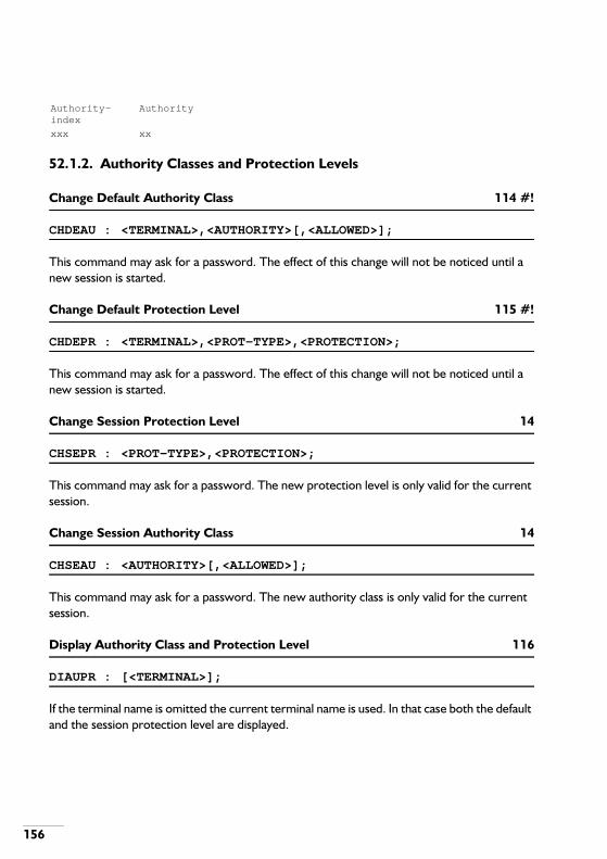
156
52.1.2. Authority Classes and Protection Levels
Change Default Authority Class 114 #!
CHDEAU : <TERMINAL>,<AUTHORITY>[,<ALLOWED>];
This command may ask for a password. The effect of this change will not be noticed until a new session is started.
Change Default Protection Level 115 #!
CHDEPR : <TERMINAL>,<PROT-TYPE>,<PROTECTION>;
This command may ask for a password. The effect of this change will not be noticed until a new session is started.
Change Session Protection Level 14
CHSEPR : <PROT-TYPE>,<PROTECTION>;
This command may ask for a password. The new protection level is only valid for the current session.
Change Session Authority Class 14
CHSEAU : <AUTHORITY>[,<ALLOWED>];
This command may ask for a password. The new authority class is only valid for the current session.
Display Authority Class and Protection Level 116
DIAUPR : [<TERMINAL>];
If the terminal name is omitted the current terminal name is used. In that case both the default and the session protection level are displayed.
Authority-index
Authority
xxx xx

157
52.2. PASSWORDS
Passwords are used by several commands. Each password is identified by a password group and a password key. The following table indicates the default passwords:Table 52-2 Default Passwords.
These default passwords can be changed by OM command CHPASS.
Change Password 235 #!
CHPASS : <PW-GROUP>,<PW-KEY>;
Response:Old Password:
New Password:
Verification:
Fill in the old password and the new password (and again the new password for verification). A password can be deleted by just entering a semi-colon when asked for the new password
Response: Default protection level (N/A/R/D): … …
(Session protection level (N/A/R/D): … …)
Default authority clas s : … … … … …
(Session authority clas s : … … … … …)
PASSWORD KEY
PASSWORD GROUP
0 1 2 3 4 5 6
AUTH. PROT. N PROT. A PROT. R PROT. D SERVICE MISC.
0 --- --- --- --- --- ---1 --- --- --- --- --- SYSTEM RISKY2 --- --- --- --- --- RISKY3 --- --- --- --- ---4 --- --- --- --- ---5 --- CONFID CONFID CONFID CONFID6 RISKY RISKY RISKY RISKY RISKY7 RISKY RISKY RISKY RISKY RISKY8 RISKY9 RISKY
10 RISKY11 RISKY12 RISKY13 RISKY --- = No password present

158
and verification. A password consists of maximum 6 characters. The following table gives the password groups and the password keys present in the groups:Table 52-3 Password Usage.
The following degradation levels are used in password group 5:
52.3. RESTRICTION LEVELS
This group of OM commands is used to determine which facility class marks and traffic classes may be assigned and deleted from a certain terminal type.
52.3.1. Facility Class Mark Restriction Levels
Change Facility Class Mark Restriction Level 228 #!
CHFCMR : <TERMINAL-TYPE>s/r[,[<FCM>s/r] [,<RESTRICTION>]];
If the facility class mark level is omitted all facility class mark levels will be changed depending on the restriction. If parameter RESTRICTION is omitted the action is restricted as a default.
PASSWORD GROUP
RELATED COMMAND DESCRIPTION PASSWORD KEY
0 CHDEAU Changing default authority class 0 … 13 (Authority class No.)0 CHSEAU Changing session authority class 0 … 13 (Authority class No.)
1 … 4 (NARD) CHDEPR Changing default protection level 0 … 7 (Protection level)1 … 4 (NARD) CHSEPR Changing session protection level 0 … 7 (Protection level)
5 SETOUT Set service condition to out of service 0 … 2 (Degradation level)5 SETNIN Set service condition to not installed 0 … 2 (Degradation level)5 FRCOUT Forcing service condition to out of
service0 … 2 (Degradation level)
5 UNIINS Set service condition of unit to installed 2 (Degradation level)5 UNININ Set service condition of unit to not
installed2 (Degradation level)
6 INIDSK Initialise disk 1CHACIV Change ACI and value relation
0 Not serious PCT boards.1 Serious PMs.2 Very serious CM, SM, CM boards, SM boards, devices, SNL, ULL, DTU and PCH.

159
Display Facility Class Mark Restriction Level 229
DIFCMR : <TERMINAL-TYPE>s/r;
Response:
52.3.2. Traffic Class Restriction Levels
Change Traffic Class Restriction Level 266 #!
CHTFCR : <TERMINAL-TYPE>s/r[,[<TRFC>s/r] [,<RESTRICTION>]];
If the traffic class level is omitted all traffic class restriction levels will be changed depending on the restriction. If parameter RESTRICTION is omitted the action is restricted as a default.
Display Traffic Class Restriction Level 277
DITFCR : <TERMINAL-TYPE>s/r;
Response:
Unrestricted facility class marks for "TERMINALTYPE"
xx xx xx xx xx xx
Unrestricted traffic classes for "TERMINAL TYPE"
x x x x x x

160
53. TESTING
53.1. PERIODIC AUTONOMOUS TESTING
Periodic Autonomous Testing (PAT) ensures that most system parts are tested from time to time. If a PAT fails the result appears in an alarm buffer. A successful test result is not displayed.
Change Periodic Autonomous Testing Mode 83
CHPATM : <PAT-MODE>[,<UNIT>s/r];
This command is used to switch the unit between the Normal and Installation/Factory test mode. In the Installation/Factory test mode the periodic autonomous test has a higher priority than the handling of telephone traffic. Periodic autonomous testing is an idle time job in the normal mode, i.e. telephone traffic is more important than testing.Remark: A fault report with alarm code 16 with qualifier 3 indicates that the Installation/Factory test mode is set.
Clear Periodic Autonomous Testing Cycle Counter 84
CLPATC : [<UNIT>s/r];
Display Periodic Autonomous Testing Cycle Counter 82
DIPATC : <RESOURCE-TYPE>s/r[,<UNIT>s/r];
Response:
53.2. MANUALLY CONTROLLED TESTING
Manually Controlled Testing (MAT) gives the possibility to insert resources in a test request list. If this test fails the result can be read out from history buffer 12. A successful test will not be displayed. The following rules apply for the hardware addresses in these command:
- If CRT is omitted, the board is indicated.
UNIT RESOURCE-TYPE CYCLE-COUNTER
xx xx xx

161
- If BRD is omitted, the module is indicated.- If BRD and CRT are omitted, the shelf is indicated.
Delete Resource from Test Request List 97
DETEST : [<SHELF>[,[<BRD>s/r][,<CRT>s/r]]];
If the shelf is not specified, ALL test requests in the system will be deleted.Response:Do you want to delete ALL manual test requests (YES/NO) : ?
Display Manual Test Requests 98
DITEST : [<SHELF>[,[<BRD>s/r][,<CRT>s/r]]];
If at least the shelf is specified the test requests STATUS and REP-FACTOR are shown, according to the following rules:STATUS = request in progress orSTATUS = request waitingRepeat factor = 0 means continuous testing, while any other value represents the number of tests for that EHWA that still has to be performed, plus the current test if the status is waiting. If an EHWA is specified, the general status of manually controlled tests is displayed. Otherwise for each unit the total number of waiting requests and requests in progress is given.If at least SHELF has been input the response is:
Otherwise:
Insert Resource into Test Request List 96
INTEST : <SHELF>[,[<BRD>s/r][,[<CRT>s/r] [,<REP-FACTOR>]]];
If the repeat factor is omitted, value 1 is used.
SHELF BRD CRT STATUS REP-FACTOR
xxxxx xx xx xx xx
UNIT # WAITING # IN PROGRESS
xx xx xx

162
53.3. TEST OF THE ALARM BOX
Test Alarm Box 233
TSALRM : [<UNIT>s/r];
In the case of a CPU-ME/MT, only the alarm output (upper socket) at the CPU-ME/MT is tested.Response:Please enter the required test state ie “on”, “off” or “end” ?
53.4. MEMORY QUALITY
This command is used to test the main memories of the four processors.
Display Memory Quality (for CPS only) 234
DIMEMQ : <SHELF>,,<CRT>;
Response:
Test completed
The output consists of a header, giving the hardware address of the four processor slices. The following lines give the block number, followed by the data for each of the four slices. The slice data is subdivided into four columns. Of these four columns:
- The first one indicates the number of hard bit faults detected (max. 9999);- The second one indicates the number of soft bit errors (max. 9999);- The third one indicates the number of times the slice contributed to a double bit error
(max. 99);- The fourth indicates whether a slice error did occur (0 or 1).
THE CM MAIN MEMORY IS UNDER TEST NOW - PLEASEBE PATIENT
BLOCK : SHELF BRD : SHELF BRD : SHELF BRD : SHELF BRD
: xxxx x : xxxx x : xxxx x : xxxx x
000 : 0000 000000 0
: 0000 000000 0
: 0000 000000 0
: 0000 000000 0
001 : 0024 000000 0
: 0000 000000 0
: 0000 000000 0
: 0000 000000 0
002 : 0000 000000 0
: 0000 000000 0
: 0000 000000 0
: 0000 000000 0

163
If the final message is not “Test completed” but “Test aborted by operating system”, this indicates that a synchronization action of the CM slices has been initiated, so there is no point in continuing the test. The test can be restarted when the synchronization action is finished.The test can be done for the following boards:
- CMS-D, 8 Mbytes, block number 0 … 127;- CPS-4M, 8 Mbytes, block number 0 … 127.
• Interpreting the Test ResultsThis test enables the maintenance engineer to locate faulty memory chips on the CMS-D/4M boards. See DB-A 9130e, Maintenance Manual.
53.5. CONTROLLED CONNECTION
The commands for controlled connections are used to establish and release a one way or a both way connection between two ports.It is also possible to make a one way connection between a Sender/Receiver Tone and a port.A connection is established by means of the commands: CRCCSP or CRCCPP. The controlled connection is released by means of command ERCOCO. The actual status of the controlled connection is displayed by means of command DICOCO. The following statuses are possible:
The service condition of the circuits which are involved, must be OUT.If a tone resource or a B-channel is involved, the circuit must be in service condition INS.A controlled connection is limited to a unit. Per unit a maximum of 5 controlled connections may be set up.
Create Controlled Connection Single Path 322
CRCCSP : <SHELF-A>,<BRD-A>[,<CRT-A>[,<B-CHANNEL-A>,<EXCLUSIVE-A>]];
The EHWA entered is that of the source EHWA. If the board number is omitted it means that a module (e.g. a PM) is addressed.The parameters B-CHANNEL and EXCLUSIVE are mandatory for ISDN ports.The system asks for the destination EHWA:
- SETUP : Controlled connection has been set up.- ACTIVE : Connection has been established and active.- ERROR : An error has been detected and the related resources released. Clear the controlled
connection by means of the ERCOCO command. Note that an action of SAS or the command FRCOUT can be the cause that a connection goes to error.
- KILL : Connection has been erased.

164
<SHELF-B>,<BRD-B>,<CRT-B>[,<B-CHANNEL-B>,<EXCLUSIVE-B>];
Create Controlled Connection Paired Path 323
CRCCPP : <SHELF-A>,<BRD-A>[,[<CRT-A>][,<B-CHANNEL-A>,<EXCLUSIVE-A>]];
If the board number is omitted it means that a module (e.g. a PM) is addressed. The parameters B-CHANNEL and EXCLUSIVE are mandatory for ISDN ports.The system asks for the destination EHWA:<SHELF-B>,<BRD-B>,<CRT-B>[,<B-CHANNEL-B>,<EXCLUSIVE-B>];
A controlled connection will be set up between A and B.
Display Controlled Connection 330
DICOCO : [<COCO-NUMBER>],[<UNIT>];
If the COCO-NUMBER is omitted the status of all controlled connections in the unit is given.Response:
Erase Controlled Connection 329
ERCOCO : <COCO-NUMBER>[,<UNIT>];
Send Controlled Connection Tone 397
SECCTO : <COCO-NUMBER>[,[<TONE-FUNCTION>],[<UNIT>]];
Before using this command, be sure that the controlled connection is established and is in the `active' state.
UN # STATE SHELF BRD CRT BB X SHELF BRD CRT BB X T
xx x xxx xxxxx x x xx x xxxx x x xx x x
SET UP TIME: [ROLL BACK TIME]

165
Send Controlled Connection Digit 398
SECCDI : <COCO-NUMBER>,<DFP-INDICATOR>,<DIGIT/FREQ> [,<UNIT>];
Before using this command, be sure that the controlled connection is established and is in the `active' state.
Display Controlled Connection Digit 399
DICCDI : <COCO-NUMBER>[,<UNIT>];
Before using this command, be sure that the controlled connection is established and is in the `active' state.Response: Received digits.
53.6. DIRECTED CALL
The directed call facility is used to test the function of receiver/sender resources. A directed call is limited to one unit.The sequence to set up a directed call is as follows:
- Directed call definition.A directed call is defined by means of command ASDICA.
- Directed call activation.The directed call is activated by means of the extension of the user. The user goes off hookand dials the directed call facility code. He receives the dial tone if the resources which aredefined for the extension are idle.
The directed call is removed from the registration list by means of command DEDICA.
Assign Resources to a Directed Call 393 #!
ASDICA : <SHELF>,<BRD>,<CRT>;
The EHWA indicates the originator. The system asks for the resource EHWA(s):<SHELF>,<BRD>,<CRT>;
The command is stopped by typing a single semi colon.

166
Delete Directed Call 395 #!
DEDICA : <SHELF>,<BRD>s/r,<CRT>s/r[,<SHELF>,<BRD>,<CRT>];
The first EHWA indicates the originator, the second is the resource EHWA.
Display Direct Call Definition 394
DIDICA : [<SHELF>,<BRD>s/r,<CRT>s/r][,<UNIT>];
Response:
ORIGINATOR RESOURCE
SHELF BRD CRT SHELF BRD CRT TYPE
xxxxx xx x xxxxx xx xx xxx
xxxxx xx xx xxx
xxxxx xx x xxxxx xx xx xxx
xxxxx xx xx xxx

167
54. TOLL TICKETING AND FULL DETAILED CALL RECORDING
The OM commands for toll-ticketing are only relevant when the system option “Full Detailed Call Recording in stead of Toll Ticketing” (60) is set to “FALSE”. Likewise the OM commands for Full Detailed Call Recording (FDCR) are only relevant when system option 60 is set to “TRUE”. Commands STOPTT and STOPFR are independent of option 60.
54.1. TOLL TICKETING
Change Thresholds of Route Number 152 #!
CHTRLV : <ROUTE>s/r,[<TICS>][,<DURATION>];
A call is only included in a call recording report, if the number of ticks (metering pulses) or the duration of the call exceeds a certain threshold. This command is used to assign these thresholds.
Display Thresholds of Route Number 153
DITRLV : [<ROUTE>s/r];
This command shows the threshold(s) of a route as set by CHTRLV.
Response:
Change Toll Ticketing Characteristics 154 #!
CHTTCR : <LINES-PER-PAGE>;
Indicates the number of lines after which a page feed is generated in the call recording file.
Change Toll Ticketing Output Definitions 155 #!
CHTTOD : [[<LDN>][,[<OUTPUT-FORMAT-VERSION>][,<UNIT>s/r]]];
Indicates to which device the toll ticketing file should be sent and in which output format. If LDN (Local Device Name) is omitted no output device is defined any more. If the output
ROUTE THRESHOLD THRESHOLD
METERING-TICS DURATION (seconds)

168
device is changed while toll ticketing is active, the “old” device remains valid until toll ticketing is restarted.
Display Toll Ticketing Output Definitions 156
DITTOD : ;
If the output device is changed while toll ticketing is active, the “old” device remains valid until toll ticketing is restarted. In this case the displayed device is not the current output device. This command is always executed system wide.The response is:
Display Toll Ticketing Status and Characteristics 151
DISPTT : ;
The response is:
Start Toll Ticketing 149 #
STRTTT : <FILE-NAME>;
Before toll ticketing can be started the output device must be specified. This can be a LBUxx, a PC, a toll-ticketing device or a printer. If necessary use DICHAR to obtain a list of valid devices. When toll ticketing is active, another toll ticketing start with a different file name may be done. This redirects the output to the other file and the old one is closed. This to prevent gaps in the TT output. The file contains the following items:
If the costcentre (CC) and costcentre type (CCT), department (DP), private/business indicator (P/B) and/or password (PSW) are not used by the caller, a blank is displayed in the related area. TETN contains the route and line number of the external line.
UNIT OUTPUT-DEVICE OUTPUT-FORMAT-VERSION
xx xxxx x
TT-OUTPUT-FILE FILE- TT- IN ACCUMULATIONS:
STATUS STATUS PROGR CALLS PULSES DUR CALLS
filename xxxx xxxxx xxxxx xxxxx xxxxx xxxxx xxxx
CC CCT DP P/B EXT IBSCP/N
PSW NUMBER DIALLED DATE TIMEDUR.
UNITS TETN
xx xx xx x xxxx xx x xxxxxx xxxx xxxxx xxxxxx
xxx xxxx

169
Stop Toll Ticketing 150 #
STOPTT : ;
This command stops toll ticketing and closes the output file.
54.2. FULL DETAILED CALL RECORDING
Change FDCR Characteristics 445 #!
CHFRCR : <FDCR-CALL-TYPE>s/r,<OFF-ON>;
This command adds or removes a FDCR call type to or from the list of recorded items. It allows you to perform call recording on a restricted set of call types.
Change FDCR Output Definitions 347 #!
CHFROD : [[<LDN>][,[<OUTPUT-FORMAT-VERSION>][,<UNIT>s/r]]];
Indicates to which device the Full Detailed Call Recording (FDCR) file should be sent and in which output format. If LDN is omitted no output device is defined any more. If the output device is changed while FDCR is active, the “old” device remains valid until FDCR is restarted.
Display FDCR Output Definitions 371
DIFROD : ;
If the output device is changed while FDCR is active, the “old” device remains valid until FDCR is restarted. In this case the displayed device is not the current output device. This command is always executed system wide.The response is:
UNIT OUTPUT-DEVICE OUTPUT-FORMAT-VERSION
xx xxxx x

170
Display Full Detailed Call Recording 345
DISPFR : ;
This command is used to display the FDCR output file. Furthermore this command displays the accumulated metering pulses and call duration time, which are lost as result of congestion on accounting records.The (example) response is:
Start Full Detailed Call Recording 340 #!
STRTFR : <FILE-NAME>;
Before FDCR can be started the output device must be specified. This can be a LBUxx, a PC or a printer. If necessary use DICHAR to obtain a list of valid devices. When FDCR is active, another FDCR start with a different file name may be done. This redirects the output to the other file and the old one is closed. This to prevent gaps in the output. For more information about this file, refer to the Facility Implementation Manual (Management Facilities).
Stop Full Detailed Call Recording 342 #!
STOPFR : ;
This command is used to close the FDCR output file.
FDCR-OUTPUT-FILE
FILE- TT- IN ACCUMULATIONS:
STATUS STATUS PROGR CALLS PULSES DUR CALLS
filename xxxxx xxxxx xxxxx xxxxx xxxxx xxxxx xxxx
Recording call types :internal calls : 1outgoing calls : 1incoming calls : 1tieline calls : 1assistance calls : 0paging calls : 0toll-ticketing calls : 1

171
55. TOOLS
55.1. NUMBER OF FREE PACKETS / ROUTING COUNTERS
The commands for tools are used to display the results of the Local Operating System (LOS) functions which monitor the routing counters, the use of software resources.For detailed information of these OM commands, reference is made to the Second Line Maintenance Manual.
Display Number of Free Packets 293
DIPOOL : [<UNIT>];
Response for CPS:
The display will be continuously and can be aborted by means of `Ctrl X'.
Display Routing Counters 292
DIROCO : <SHELF>,<BRD>[,<CRT>s/r];
It is possible to display the routing counters of other units.Response:
PCB PACB CB SIG BUF SDB MDB LDB IOM STCK CDB
0568 0565 0563 0400 0500 0028 0400 0179 810 0099 400
SHELF BRD CRT CHNL DESTINATION: C1:C2:
C3:C4:
C5:C6:
C7:C8:
xxxx xx xx x xxxx xx x x x x x x x x

172
56. TRAFFIC CLASSES
Change Traffic Class of DNR/BSP 16 #!
CHTRFC : [DAY-TRFC>],[<NIGHT-TRFC>],[UP-TRFC>],[<DOWN-TRFC>],<BSP-ID>s/r;
If any of the parameters DAY-TRFC, NIGHT-TRFC, UP-TRFC or DOWN-TRFC is omitted the corresponding traffic class is not changed.Initially the UP-TRFC will be the same as the DAY-TRFC and the DOWN-TRFC will be the same as the NIGHT-TRFC.The DNR part of the BSP-ID is sufficient as long as the DNR is unique.If the DNR is an operator DNR only the DAY-TRFC is relevant.
Display Traffic Class of DNR/BSP 17
DITRFC : <BSP-ID>s/r;
If the traffic class of an operator DNR is displayed only the DAY-TRFC is displayed.Response:
DNR-BSPT
DAY-TRFC
NIGHT-TRFC UP-TRFC
DOWN-TRFC
xxxxxx xx xx xx xx

173
57. TRAFFIC OBSERVATIONS AND MEASUREMENTS
57.1. TRAFFIC OBSERVATIONS
The command for traffic observation is used to scan and display the dynamic and static data of various resources in the system.The static data is read out when the command is executed. It consists of:
- Number of resources in OUT;- Number of resources in ABL;- Number of resources in NIN;- Total number of resources in a pool;- Total number of B-channels (ISDN only);- Not usable B-channels (ISDN only).
The dynamic data is scanned with a higher frequency. If the dynamic data changes a new output line is generated. Dynamic data comprises:
- Number of busy resources;- Number of idle resources;- Number of congested resources (never reset);- Number of Camp On Busy situations on resources;- Etc.
Data about the following resources can be observed with this command:
- Bundle and route data;- Inter unit bundle and route data;- Extension and group data;- Paging route data;- Add On Circuit (AOC) data;- RKT-SDT and SKT-RDT data;- Incoming and outgoing MFC data;- Socotel data;- Convertor data;- Operator data and data about queues;- Switching Network Channel (SNC) data;- Call data;- Inter Unit Traffic Dispersion;- Dialled Facilities;

174
- Hatch data .
Display Result of Traffic Observations 209
DITRAF : <OBJECT>;
The command will ask for additional parameters, depending on the selected object. Note that only objects without an asterisk (*) can be used for this command. See appendix B. parameter OBJECT.The result of this command is some static and some dynamic data.This command can be executed in the following ways:
- Display traffic observations of bundle:
DITRAF:0;
Enter bundle number:30;
Enter unit number:1;
Response:
- Display traffic observations of route:
DITRAF:1;
Enter route number:30;
Response:
- Display traffic observations of inter unit bundle:
DITRAF:2;
OBSERVED-ITEM STATIC-DATA
BUNDLE UNIT OUT ABL NIN TOTAL BCH BCH-NIN
xxx xx x x x x x x
OBSERVED-ITEM DYNAMIC-DATA
BUNDLE UNIT BUSY CONG
xxx xx xx xx
OBSERVED-ITEM STATIC-DATA
ROUTE OUT ABL NIN TOTAL BCH BCH-NU
xxx x x x x x x
OBSERVED-ITEM DYNAMIC-DATA
ROUTE UNIT BUSY CONG COBS
xxx xx xx xx xx

175
Enter interunit bundle number:10;
Enter unit number:1;
Response:
- Display traffic observations of inter unit route:
DITRAF:3;
Enter interunit route number: 10;
Enter unit number:1;
Response:
- Display traffic observations of extensions:
DITRAF:4;
Enter unit number:1;
Response:
- Display traffic observations of extension or group:
DITRAF:5;
Enter extension <BSP-ID> or group <DNR>:1311;
Response:
OBSERVED-ITEM STATIC-DATA
IU-BUNDLE UNIT OUT ABL NIN TOTAL
xxx xx x x x x
OBSERVED-ITEM DYNAMIC-DATA
IU-BUNDLE UNIT BUSY CONG
xxx xx xx xx
OBSERVED-ITEM STATIC-DATA
IU-ROUTE UNIT OUT ABL NIN TOTAL
xxx xx x x x x
OBSERVED-ITEM DYNAMIC-DATA
IU-ROUTE UNIT BUSY CONG
xxx xx xx xx
OBSERVED-ITEM DYNAMIC-DATA
EXTENSION-UNIT BUSY RING
xx xx xx
OBSERVED-ITEM DYNAMIC-DATA

176
- Display traffic observations of paging route:
DITRAF:6;
Enter paging route number:40;
Response:
- Display traffic observations of Add On Circuit (7), RKT-SDT (8), SKT-RDT (9), IncomingMFC (10), Outgoing MFC (11), Socotel data (12) or Hatch (21):
DITRAF:7 . . 12 and 21;
Enter unit number:1;
Response:
- Display traffic observations of convertor:
DITRAF:13;
Enter convertor type:0;
Enter unit number:1;
Response:
DNR-BSPT TYPE PRES ABS BUSY RING COB UNS-BIDS
xxx-xx xxx xx xx xx xx xx xx
OBSERVED-ITEM STATIC-DATA
PAG-ROUTE UNIT OUT ABL NIN TOTAL
xxx xx x x x x
OBSERVED-ITEM DYNAMIC-DATA
PAG-ROUTE UNIT BUSY CONG COBS
xxx xx xx xx xx
OBSERVED-ITEM STATIC-DATA
RES-ID UNIT OUT ABL NIN TOTAL
xxx xx x x x x
OBSERVED-ITEM DYNAMIC-DATA
RES-ID UNIT BUSY CONG
xxx xx xx xx
OBSERVED-ITEM STATIC-DATA
IU-ROUTE UNIT OUT ABL NIN TOTAL
xxx xx x x x x
OBSERVED-ITEM DYNAMIC-DATA
IU-ROUTE UNIT BUSY CONG
xxx xx xx xx

177
- Display traffic observations of specific operator:
DITRAF:14;
Enter operator <DNR>:8991;
Response for specific DNR:
General response:
- Display traffic observations of queues:
DITRAF:15;
Enter queue type:0;
Enter assistance group:;
Enter unit number:1;
Response:
- Display traffic observations of Switching Network Channels:
DITRAF:16;
Enter PMC/PSC address <SHELF>, <BRD>:1011,17;
OBSERVED-ITEM DYNAMIC-DATA
OP-DNR OP-STAT
M-IND WA UA C-SER* C-TAX* C-BUSY*
C-RING*
C-PRE*
xxx xxx x x x x x x x x
OBSERVED-ITEM STATIC-DATA
OPERATOR-UNIT OUT ABL NIN TOTAL
xx x x x x
OBSERVED-ITEM DYNAMIC-DATA
OPERATOR-UNIT PRES PRES-CH
PRES-POM
ABS-POM
ABS
xx xx xx xx xx xx
* C-SER: series call rerouted to the C queueC-TAX: tax metering informationC-BUSY: call to a busy extension rerouted to the C queueC-RING: call which encountered ringing time out rerouted to the C queueC-PRE: preferred calls
OBSERVED-ITEM DYNAMIC-DATA
ASSIST-GROUP UNIT M-QUEUE
C-QUEUE
A-QUEUE
xx xx xx xx xx

178
Response:
- Display traffic observations of calls:
DITRAF:17;
Enter single or multi unit calls:1; (0=single, 1=multi)Enter unit number:1;
Response for a multi unit system:
Response for a single unit system:
57.2. TRAFFIC MEASUREMENT
If Traffic Measurement must take place, do the following:
- Put the object to be observed in the Object List.- Enter the time and length of the measurement. As an alternative it is possible to start and
stop the measurement manually.- Traffic Measurement data is stored in a buffer. This contents of this buffer can be displayed
on the screen with DISPTO. If an output device and file name have been assigned it willalso be written to a file.
OBSERVED-ITEM DYNAMIC-DATA
SHELF-BRD-CRT BUSY CONG
xxx - xx xx xx
OUTSTANDING MULTI UNIT CALLS IN REQUESTED UNIT
SOURCE: EXT OPE OPE OPE NE NE NE EXT TRK EXT TRK TRK
UNITDESTIN:
EXT EXT TRK OTH EXT TRK OTH TRK EXT PAG PAG TRK
xx xx xx xx xx xx xx xx xx xx xx xx xx
OUTSTANDING SINGLE UNIT CALLS IN REQUESTED UNIT
SOURCE: EXT OPE OPE OPE NE NE NE EXT TRK EXT TRK TRK
UNITDESTIN:
EXT EXT TRK OTH EXT TRK OTH TRK EXT PAG PAG TRK
xx xx xx xx xx xx xx xx xx xx xx xx xx

179
57.2.1. Start, Stop and Status
Start Traffic Measurement Observation 374
STRTTM : <PERIODS>;
Stop Traffic Measurement Observation 379
STOPTM : <OUTPUT-SWITCH>;
Display Traffic Measurement Status 387
DISPTM : ;
Response:
57.2.2. Timing
Assign Traffic Measurement Timing 380
ASTMTI : <ON-TIME>,<PERIODS>,<CYCLIC>;
The previous measurement must end 15 minutes before the next one starts.Cyclic means that the measurement is done weekly, depending on a system boundary.
Delete Traffic Measurement Timing 381
DETMTI : [<ON-TIME>];
ON-TIME indicates the start time of the measurement that has to be erased. If it is omitted, all programmed measurements are deleted.
UNIT START START TOTAL CURR NOT-OUT
MEAS FILE
DATE TIME PERIODS
PERIOD PERIODS
STATUS STATUS
xx xxxxx xxxxx xx xx xx xx xx

180
Display Traffic Measurement Timing 382
DITMTI : ;
Response:
57.2.3. Output
Change Traffic Measurement Output Device 383!
CHTMOD : [<LDN>][,<UNIT>s/r];
If the Logical Device Name (LDN) is omitted no output device is defined any more.
Change Traffic Measurement Output File Name 385!
CHTMOF : [<FILE-NAME>];
If FILE-NAME is omitted no output file is defined any more.
Display Traffic Measurement Output Device 384
DITMOD : ;
This command is always executed system wide.Response:
Display Traffic Measurement Output File Names 386
DITMOF : ;
Response:
ON-TIME
PERIODS
CYCLIC
xxxx xxxx xxx
UNIT CURR-DEVICE NEW-DEVICE
xx xxxxxx xxxxxx
CURR-FILENAME NEW-FILENAME
xxxxxx xxxxxx

181
Display Traffic Measurement Object Figures 388
DISPTO : <OBJECT>;
See parameter Object. This parameter must be present on the object list.The command will ask for additional parameters. Which parameters, depend on the entered objects. Response: Traffic measurement data.
57.2.4. Object List
Assign Traffic Measurement Object 378
ASTMOB : <OBJECT>;
Delete Traffic Measurement Object 375
DETMOB : <OBJECT>;
Display Traffic Measurement Object List 376
DITMOB : [<UNIT>s/r];
Response:
Erase Traffic Measurement Object List 377
ERTMLI : [<UNIT>s/r];
If UNIT is omitted all the lists in all the units are erased.
UNIT OBJECT-GROUP OBJECT-INDEX
xx xxxxxx xxxxxx

182
57.2.5. Output Formats
The result of the traffic measurement is a file or the display of data on the screen. The output varies with the selected object for traffic measurement. The time (e.g. average holding time) in this output is given in seconds, the carried load in Erlangs.The following pages describe the format of the screen output (DISPTO).When the output is written to a file, the file consists of lines, starting with the unit number, object number and followed by numbers. An example of such a file is given for object 0:1 STATIC FIGURES
1 0 5 24 0 0 0 0 0
1 END STATIC FIGURES
1 DYNAMIC FIGURES
1 0 5 20.4 0.30 12 23 34
1 END DYNAMIC FIGURES
The static data in the example above consists of:
The dynamic data in the example above consists of:
Compare this output with the screen output given on the next pages.
Note: The figures in brackets given in the outputs of the objects 14 and 15 are not part of the screen layout but indicate the number in the traffic measurement output file.
The objects numbers have the following meanings:
1 = Unit number0 = Object: Exchange and Tie Line Bundles5 = Bundle number
24 = Total circuits0 = Circuits in OUT0 = Circuits in NIN0 = Circuits in ABL0 = Total B-channels0 = Not usable B-channels
1 = Unit number0 = Object5 = Bundle number
20.4 = Average holding time0.30 = Carried load
12 = Incoming seizures23 = Outgoing seizures34 = Congestion

183
• Object 0, Exchange and Tie Line Bundles
• Object 1, Exchange and Tie Line Routes
• Object 2, Inter Unit Bundles
• Object 3, Inter Unit Routes
• Object 4, All Extensions In a Unit
Average holding time : xxx .xx
Carried load : xxx .xx
Incoming seizures : xxxxxxxxxxxx
Outgoing seizures : xxxxxxxxxxxx
Congestion : xxxxxxxxxxxx
Total Circuits : xxx
Circuits in OUT : xxx
Circuits in NIN : xxx
Circuits in ABL : xxx
Total B-channels : xxx
Not usable B-channels : xxx
COB started : xxxxxxxxxxxx
COB to seizure : xxxxxxxxxxxx
Congestion : xxxxxxxxxxxx
Total Circuits : xxx
Circuits in OUT : xxx
Circuits in NIN : xxx
Circuits in ABL : xxx
Total B-channels : xxx
Not usable B-channels : xxx
Average holding time : xxx .xx
Carried load : xxx .xx
Congestion : xxxxxxxxxxxx
Total Circuits : xxx
Circuits in OUT : xxx
Circuits in NIN : xxx
Circuits in ABL : xxx
Congestion : xxxxxxxxxxxx
Total Circuits : xxx
Circuits in OUT : xxx
Circuits in NIN : xxx
Circuits in ABL : xxx

184
• Object 5, Extension Groups
• Object 6, Paging Routes (Real Paging)
• Object 6, Paging Routes (Virtual Paging)
• Object 7, Add-on Circuits
Average holding time : xxx .xx
Carried load : xxx .xx
COB started : xxxxxxxxxxxx
COB to ringing : xxxxxxxxxxxx
Average ringing time : xxx .xx
Ringing started : xxxxxxxxxxxx
Answered : xxxxxxxxxxxx
Average holding time : xxx .xx
Carried load : xxx .xx
COB started : xxxxxxxxxxxx
COB to ringing : xxxxxxxxxxxx
Average ringing time : xxx .xx
Ringing started : xxxxxxxxxxxx
Answered : xxxxxxxxxxxx
Average No of COBs : xxx .xx
Average COB time : xxx .xx
Unsuccessful bids : xxxxxxxxxxxx
Present groupmembers : xxx
Absent groupmembers : xxx
Average holding time : xxx .xx
Carried load : xxx .xx
COB started : xxxxxxxxxxxx
COB to seizure : xxxxxxxxxxxx
Congestion : xxxxxxxxxxxx
Total Circuits : xxx
Circuits in OUT : xxx
Circuits in NIN : xxx
Circuits in ABL : xxx
Average holding time : xxx .xx
Carried load : xxx .xx
Congestion : xxxxxxxxxxxx
Total Circuits : xxx
Average holding time : xxx .xx
Carried load : xxx .xx

185
• Object 8, RKT-SDTs
• Object 9, SKT-RDTs
• Object 10, Incoming MFC Circuits
• Object 11, Outgoing MFC Circuits
• Object 12, RS-Socotel Circuits
Congestion : xxxxxxxxxxxx
Total Circuits : xxx
Circuits in OUT : xxx
Circuits in NIN : xxx
Circuits in ABL : xxx
Average holding time : xxx .xx
Carried load : xxx .xx
Congestion : xxxxxxxxxxxx
Total Circuits : xxx
Circuits in OUT : xxx
Circuits in NIN : xxx
Circuits in ABL : xxx
Average holding time : xxx .xx
Carried load : xxx .xx
Congestion : xxxxxxxxxxxx
Total Circuits : xxx
Circuits in OUT : xxx
Circuits in NIN : xxx
Circuits in ABL : xxx
Average holding time : xxx .xx
Carried load : xxx .xx
Congestion : xxxxxxxxxxxx
Total Circuits : xxx
Circuits in OUT : xxx
Circuits in NIN : xxx
Circuits in ABL : xxx
Average holding time : xxx .xx
Carried load : xxx .xx
Congestion : xxxxxxxxxxxx
Total Circuits : xxx
Circuits in OUT : xxx
Circuits in NIN : xxx
Circuits in ABL : xxx

186
• Object 13, Convertors
• Object 14, Operators
• Object 15, Operator Queues
Average holding time : xxx .xx
Carried load : xxx .xx
Congestion : xxxxxxxxxxxx
Total Circuits : xxx
Circuits in OUT : xxx
Circuits in NIN : xxx
Circuits in ABL : xxx
Average holding time : xxx .xx
Carried load : xxx .xx
Congestion : xxxxxxxxxxxx
Total Circuits : xxx
Circuits in OUT : xxx
Circuits in NIN : xxx
Circuits in ABL : xxx
Average holding time : xxx .xx
Carried load : xxx .xx
AVERAGE AVERAGE QUEUED HANDLED
QUEUE QUEUELENTGTH
QUEUE TIME CALLS CALLS
(0) M individual xxx.xx xxx.xx xxxxxxxxxxx xxxxxxxxxxx
(28) WA xxx.xx xxx.xx xxxxxxxxxxx xxxxxxxxxxx
(29) UA xxx.xx xxx.xx xxxxxxxxxxx xxxxxxxxxxx
(10) C preferred xxx.xx xxx.xx xxxxxxxxxxx xxxxxxxxxxx
(7) C series xxx.xx xxx.xx xxxxxxxxxxx xxxxxxxxxxx
(8) C taxmetering xxx.xx xxx.xx xxxxxxxxxxx xxxxxxxxxxx
(9) C through connec t busy xxx.xx xxx.xx xxxxxxxxxxx xxxxxxxxxxx
(11) C through connectringing
xxx.xx xxx.xx xxxxxxxxxxx xxxxxxxxxxx

187
• Object 16, Switching Network ChannelsCongestion : xxxxxxxxxx
AVERAGE AVERAGE QUEUED HANDLED
QUEUE QUEUELENTGTH
QUEUE TIME CALLS CALLS
(1) M noRMAL xxx.xx xxx.xx xxxxxxxxxxx xxxxxxxxxxx
(2) M preferred xxx.xx xxx.xx xxxxxxxxxxx xxxxxxxxxxx
(3) C ddi not answered xxx.xx xxx.xx xxxxxxxxxxx xxxxxxxxxxx
(4) C ddi unsuccessful xxx.xx xxx.xx xxxxxxxxxxx xxxxxxxxxxx
(5) C recall not on hook xxx.xx xxx.xx xxxxxxxxxxx xxxxxxxxxxx
(6) C recall on hook xxx.xx xxx.xx xxxxxxxxxxx xxxxxxxxxxx
(12) A1 xxx.xx xxx.xx xxxxxxxxxxx xxxxxxxxxxx
(13) A2 xxx.xx xxx.xx xxxxxxxxxxx xxxxxxxxxxx
(14) A3 xxx.xx xxx.xx xxxxxxxxxxx xxxxxxxxxxx
(15) A4 xxx.xx xxx.xx xxxxxxxxxxx xxxxxxxxxxx
(16) A5 xxx.xx xxx.xx xxxxxxxxxxx xxxxxxxxxxx
(17) A6 xxx.xx xxx.xx xxxxxxxxxxx xxxxxxxxxxx
(18) A7 xxx.xx xxx.xx xxxxxxxxxxx xxxxxxxxxxx
(19) A8 xxx.xx xxx.xx xxxxxxxxxxx xxxxxxxxxxx
(20) A9 xxx.xx xxx.xx xxxxxxxxxxx xxxxxxxxxxx
(21) A10 xxx.xx xxx.xx xxxxxxxxxxx xxxxxxxxxxx
(22) A11 xxx.xx xxx.xx xxxxxxxxxxx xxxxxxxxxxx
(23) A12 xxx.xx xxx.xx xxxxxxxxxxx xxxxxxxxxxx
(24) A13 xxx.xx xxx.xx xxxxxxxxxxx xxxxxxxxxxx
(25) A14 xxx.xx xxx.xx xxxxxxxxxxx xxxxxxxxxxx
(26) A15 xxx.xx xxx.xx xxxxxxxxxxx xxxxxxxxxxx
(27) A16 xxx.xx xxx.xx xxxxxxxxxxx xxxxxxxxxxx

188
All PMs in a specific unit will be observed. Therefore, only additional parameter for unitnumber is asked.For each quarter of an hour, the data of the first PM is written to the output file of trafficmeasurement. Data of other PMs is only written to the output file when the data ischanged.OM command DISPTO can be used to display the data of a specific PM.
• Object 17, Calls
• Object 18, Inter Unit Traffic Dispersion
Single Unit:
SOURCE DEST INTRA UNIT INTRA UNIT
CALL TYPE AV.DURATION
EST. CALLS (AV. = AVERAGE)
Ext Ext xxx.xx xxxxxxxxxx (EST. = ESTABLISHED)
Ope Ext xxx.xx xxxxxxxxxx
Ope Ope xxx.xx xxxxxxxxxx
Ope Oth xxx.xx xxxxxxxxxx
Spec-ext Ext xxx.xx xxxxxxxxxx
Spec-ext Trk xxx.xx xxxxxxxxxx
Spec -ext
Oth xxx.xx xxxxxxxxxx
Ext Trk xxx.xx xxxxxxxxxx
Trk Ext xxx.xx xxxxxxxxxx
Ext Pag xxx.xx xxxxxxxxxx
Trk Pag xxx.xx xxxxxxxxxx
Trk Trk xxx.xx xxxxxxxxxx
Multi Unit:
SOURCE DEST INTRA UNIT INTRA UNIT INTER UNIT INTER UNIT
CALL TYPE AV.DURATION
EST. CALLS AV.DURATION
EST. CALLS (AV. = AVERAGE)
Ext Ext xxx.xx xxxxxxxxxx xxx.xx xxxxxxxxxx (EST. =ESTABLISHED)
Ope Ext xxx.xx xxxxxxxxxx xxx.xx xxxxxxxxxx
Ope Ope xxx.xx xxxxxxxxxx xxx.xx xxxxxxxxxx
Ope Oth xxx.xx xxxxxxxxxx xxx.xx xxxxxxxxxx
Spec-ext Ext xxx.xx xxxxxxxxxx xxx.xx xxxxxxxxxx
Spec-ext Trk xxx.xx xxxxxxxxxx xxx.xx xxxxxxxxxx
Spec -ext
Oth xxx.xx xxxxxxxxxx xxx.xx xxxxxxxxxx
Ext Trk xxx.xx xxxxxxxxxx xxx.xx xxxxxxxxxx
Trk Ext xxx.xx xxxxxxxxxx xxx.xx xxxxxxxxxx
Ext Pag xxx.xx xxxxxxxxxx xxx.xx xxxxxxxxxx
Trk Pag xxx.xx xxxxxxxxxx xxx.xx xxxxxxxxxx
Trk Trk xxx.xx xxxxxxxxxx xxx.xx xxxxxxxxxx

189
• Object 19, Dialled Facilities
• Object 21, Hatch
DestinationUnit
1 : xxxxxxxxxx
DestinationUnit
2 : xxxxxxxxxx
DestinationUnit
3 : xxxxxxxxxx
DestinationUnit
4 : xxxxxxxxxx
DestinationUnit
5 : xxxxxxxxxx
DestinationUnit
6 : xxxxxxxxxx
DestinationUnit
7 : xxxxxxxxxx
DestinationUnit
8 : xxxxxxxxxx
DestinationUnit
9 : xxxxxxxxxx
DestinationUnit
10 : xxxxxxxxxx
DestinationUnit
11 : xxxxxxxxxx
DestinationUnit
12 : xxxxxxxxxx
DestinationUnit
13 : xxxxxxxxxx
DestinationUnit
14 : xxxxxxxxxx
Internal
: xxxxxxxxxx
Assisted
: xxxxxxxxxx
External
: xxxxxxxxxx
Average holding time : xxx .xx
Carried load : xxx .xx
Congestion : xxxxxxxxxxxx
Total Circuits : xxx
Circuits in OUT : xxx
Circuits in NIN : xxx
Circuits in ABL : xxx

190
58. TRUNK TRAFFIC
The commands for trunk traffic are used to enter and display data needed for external traffic (both incoming and outgoing). OM for trunk traffic is divided as follows:
- First the destinations are defined (for outgoing traffic).Destinations are related to a trunk access code or a network access code.
- One or more route tables are allocated to a destination to determine the different routingpossibilities to this destination (route numbers)
- More destinations can lead to the same rota.Each route has a unique number.
- A route consists of one or more bundles.Bundles are numbered per unit.
- A bundle consists of lines (trunk circuits).All lines in a bundle have the same characteristics and are linked to the EHWA of a trunkcircuit.
- For ISDN bundles an extra level is present. Within the bundle ISDN trunk circuits areassigned. Within these trunk circuits the B-channels (the actual trunk lines) are present.The B-channels of one circuit should all be assigned to the same bundle.
58.1. DESTINATIONS
Destinations are only used for outgoing traffic and are related to an access code. Dialling the same access code always results in the same destination, independent of the unit where the code was dialled. Destination numbers are unique in the system.
Change Destination Characteristics 157 #!
CHDSTC : <DEST>,<TREE>,<FST-DT>,<SND-DT>,<ROUTE-TABLE> [,<ACC-REP>];
This command defines the network characteristics of a destination. If characteristics were already defined for the destination the old ones will be overwritten by the new characteristics. This gives the possibility to introduce changes in the external numbering scheme. In this case a new analysis tree must be defined, after which the old tree is replaced by the new tree. If ACC-REP is omitted, the access code repetition counter is set to 0.

191
Display Destination Data 171
DIDEST : <DEST>;
This command shows the characteristics of a destination and which route tables there are to this destination.Response:
58.2. ROUTE TABLES
Change Route Table 406 #!
CHROTA : <ROUTE-TABLE>[,[<USER-TYPE>][,<SEQUENCE-TABLE>][,<UNIT>]];
When USER-TYPE is omitted, all user types will be adapted. When SEQUENCE-TABLE is omitted, 1 is assumed.Additional parameters:<ROUTE>,<PREF-CODE>,<TRFC>[,<SMART-BOX-EM>];When all additional parameters are omitted, the contents of the route table will be erased.The command will repeat this question up to 8 times, or until it is terminated with a single semi-colon.
Display Route Table 337
DIROTA : <ROUTE-TABLE>s/r[,[<SEQUENCE-TABLE>s/r] [,<UNIT>]];
When SEQUENCE-TABLE is omitted, 1 is assumed.Response:
DEST TREE FST-DT SND-DT ACC-REP
ROUTE-TABLE
XXX XXX X X X XXX D/P (D = Definitive; P =Provisional)
ROUTE-TABLE UNIT SEQUENCETABLE
xx xx xx
NORMAL EXTENSION OPERATOR PRIORITY EXTENSION
ROUTE PREF TRFC SMART ROUTE PREF TRFC SMART ROUTE PREF TRFC SMART
xx xx xx xx xx xx xx xx xx xx xx xx

192
58.3. ROUTES
A rota has one or more routes assigned to it. The route numbers are unique in a system.
58.3.1. Routes General
Create Route 159 #!
CRROUT : <ROUTE>[,<UNIT>];
If a route with the same route number already exists the command is rejected.
Display Route Data 172
DIROUT : <ROUTE>[,<BSPT>];
When the BSPT parameter is omitted default BSPT 98 is displayed.Response:
Erase Route 160 #!
ERROUT : <ROUTE>;
This command is only accepted when the route is known in the system and when there are no bundles and no SCNEs and/or OVEs assigned to it any more.
ROUTE UNIT BSPT GEN-OPTS
GEN-TONE
CV CC_TABLE
INC-OPTS
TONE-AND-DDI-OPTS TREE A-QUEUE
OVE SCNE
OUT-OPTS
ATF
ORIG-NUMBER to CONV-NUMBER or "NO DIGIT CONVERSION ASSIGNED ON THISROUTE"
SEQ BUNDLE

193
58.3.2. Route Characteristics
Change Route Characteristics General 161 #!
CHRTCG : <ROUTE>,<GEN-OPTS>,<GEN-TONE>[,[<CV>][,<BSPT>] [,<CC-TABLE>]]];
If the compatibility value is omitted the default value will be valid. If the BSPT is omitted the default value (98) is valid. The command will only be accepted if the route and the BSPT are already known in the system. If general characteristics were already defined the old ones will be overwritten by the new ones.Parameter CC-TABLE represents the CLI or COL translation table, which is introduced in SSW 805.29
Change Route Characteristics Incoming 162 #!
CHRTCI : <ROUTE>,<INC-OPTS>,<TONE-AND-DDI-OPTS>[,[<TREE>][,[<A-QUEUE>][,<BSPT>]]];
If in INC-OPTS P=0 then:
- V, W, X and Y must be omitted;- TREE must be omitted;- In TONE-AND-DDI-OPTS only P and Q must be given.
If A-QUEUE is omitted calls are routed to the A16 general queue.If the BSPT is omitted the default value (98) is valid.
Change Route Characteristics Outgoing 163 #!
CHRTCO : <ROUTE>,<OUT-OPTS>,<ATF>[,<BSPT>];
If the BSPT is omitted the default value (98) is valid.
58.3.3. Digit Conversion
See the DIROUT command to display the incoming digit conversions.

194
Assign Digit Conversion to an Incoming Route 164 #!
ASDGCV : <ROUTE>,[<ORIG-NUMBER>][,<CONV-NUMBER>];
Either ORIG-NUMBER or CONV-NUMBER may be omitted. If the route is not known to the system the command will be rejected.
Erase Digit Conversion from an Incoming Route 165 #!
ERDGCV : <ROUTE>;
All digit conversions are erased from the route.
Assign Digit Conversion on Outgoing Route 390 #!
ASDGCO : <ROUTE>,<DEST>,[<ORIG-NUMBER>][,[<CONV-NUMBER>][,<DIALTONE-PLACE>]];
Either ORIG-NUMBER or CONV-NUMBER may be omitted. If the route is not known to the system the command will be rejected.
Erase Digit Conversion from an Outgoing Route 391 #!
ERDGCO : <ROUTE>[,[<DEST>][,<ORIG-NUMBER>]];
The selected digit conversions are erased from the route.
Display Digit Conversion on Outgoing Route 400
DIDGCO : <ROUTE>s/r[,[<DEST>][,<ORIG-NUMBER>]];
Response:
58.3.4. CLI or COL Translation For ISDN
The 'CLI/COL translation for ISDN' enables users to be presented to the Public ISDN by another CLI (Calling Line Identity) or COL (Connected Line Identity). This is especially
ROUTE DESTINATION ORIGINALNUMBER
CONVERTEDNUMBER
xx xxx xxx xxxx

195
required for extensions which are not enabled to be reached directly from the public network. When these extensions are engaged in a call via ISDN to the public network, they send an invalid DNR, which may lead to confusion in the public network. This facility enables users to express with which CLI or COL they wish to be presented to the ISDN. The following examples show some of the possible combinations:
- non-DDI extensions;- All or some extensions send the general access number as CLI or COL;- Groupmembers send their group DNR.
The 'CLI/COL translation for ISDN' can only be used for calls to or from the ISDN.
Change CLI and COL Translation 514 #!
CHCCTR : <CC-TABLE>s[,<ORIG-CC-STRING> [,[<DEST-CC-STRING>]]];
Add a new entry to the specified CC-table or redefine an existing translation in the specified CC-table.It is possible to use wildcards in both the ORIG-CC-STRING and the DEST-CC-STRING. The wildcard character which can be used is '%'. This character stands for only one digit. Wildcards can only be used to terminate the strings. So 123%% is possible, while 12%4% is not.When wildcards are used in the ORIG-CC-STRING, for example 123%%, then all 5-digit CLI or COL strings which start with 123 are translated according to the specified translation.When wildcards are used in the DEST-CC-STRING, for example 45%%, then the last two digits are copied from the last two digits in the CLI or COL, which is to be translated.Example:CHCCTR: 1,123%%,45%%;Now the CLI or COL of extension 12345 is translated to 4545.When DEST-CC-STRING is left empty (not omitted, do not forget the comma!)) the system sends an empty CLI or no COL to the ISDN.When DEST-CC-STRING is omitted, the entry is deleted from the specified CC-table. It is possible to use wildcards in the ORIG-CC-STRING, but only that exact entry will be deleted. The wildcard mechanism can not be used to delete a number of entries which start with the same digits.When ORIG-CC-STRING and DEST-CC-STRING are omitted, the complete specified CC-table is deleted (after confirmation).

196
Display CLI and COL Translation 515 #!
DICCTR : <CC-TABLE>s[,<ORIG-CC-STRING>];
When ORIG-CC-STRING is omitted, all entries in the specified CC-table are displayed.When ORIG-CC-STRING is specified, but no exact match can be found in the CC-TABLE, then a wildcarded entry is searched for and, when found, displayed.The ORIG-CC-STRING itself may also contain wildcards, but it can not be used to display all translation entries which start with the same digits. Only the best matched entry in the CC-TABLE is displayed.
Display CC-Table/Route Relation 512 #!
DICCRT : <CC-TABLE>s/r;
This command displays all routes which use the specified CC-table to translate CLI or COL strings.
58.3.5. Route-BSPT Relation
Assign BSPT to Route 54 #!
ASBSPR : <ROUTE>,<BSPT>;
BSPT 98 and 99 may not be assigned. When a new BSPT is assigned to a route it will have the same set of characteristics as the default BSPT (98).
Display BSPT of a Route 63
DIBSPR : <ROUTE>;
Response:
Erase BSPT from Route 59 #!
ERBSPR : <ROUTE>,<BSPT>;
BSPT 98 cannot be removed from a route.
ROUTE BSPT
xx xx

197
58.4. BUNDLES
Bundles are assigned to routes. They are numbered per unit, so the same number may occur more than once in a multi-unit system.
58.4.1. Bundles General
Assign Bundle to Route 167 #!
ASBNDL : <ROUTE>,<BUNDLE>;
The signalling type of the first bundle assigned to a route determines if this route will be a DPNSS route or not. It is not allowed to mix DPNSS bundles and non-DPNSS bundles in one route.Note that for a DPNSS route the signalling type must be set with CHBNDC before assigning bundles to the route, because the default signalling type is non-DPNSS.
Change Bundle Characteristics 166 #!
CHBNDC : <UNIT+BUNDLE>,<DIR-AND-NEG>,<OPTIONS>, <CON-AND-SIG-TYPE>[,[<ALL-CALLS>][,<BSPT>]];
If ALL-CALLS is omitted, there is no restriction on the maximum number of allowed calls.If BSPT is omitted BSPT 98 will be valid.
Delete Bundle from Route 168 #!
DEBNDL : <ROUTE>,<BUNDLE>;
Display Bundle Data 173
DIBNDL : <UNIT+BUNDLE>[,<BSPT>];
Response:
BUNDLE BSPT ROUTE UNIT DIR-AND-NEG OPTIONS
CON-AND-SIG-TYPE
ALL-CALLS
xx xx xx xx x xxxxxxxxxxxxxx xx xx

198
58.4.2. Bundle-BSPT Relation
Assign BSPT to Bundle 55 #!
ASBSPB : <UNIT+BUNDLE>,<BSPT>;
BSPT 98 and 99 may not be assigned. When a new BSPT is assigned it will have the same set of characteristics as the default BSPT (98).
Display BSPT of a Bundle 77
DIBSPB : <UNIT+BUNDLE>;
Response:
Erase BSPT from Bundle 60 #!
ERBSPB : <UNIT+BUNDLE>,<BSPT>;
58.4.3. Digital Bundles
All DTUs can have Bundle - DTU relations except the DTU-CC and the ISDN DTUs (DTU-BA and DTU-PH). A relation with bundles can be assigned to make outgoing calls impossible in case of a DTU alarm.
Change Bundle - DTU Relation 175 #!
CHBDTU : <UNIT+BUNDLE>[,<SHELF>,<BRD>];
If the shelf and board are omitted the bundle - DTU relation is erased.
SEQ SHELF BRD CRT B-CH LINE or "NO LINES ASSIGNED TO THISBUNDLE"
xx xx xx xx xx xx
BUNDLE BSPT
xx xx
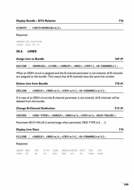
199
Display Bundle - DTU Relation 176
DIBDTU : <UNIT+BUNDLE>s/r;
Response:
58.5. LINES
Assign Line to Bundle 169 #!
ASLINE : <BUNDLE>,<LINE>,<SHELF>,<BRD>,<CRT>[,<B-CHANNEL>];
When an ISDN circuit is assigned and the B-channel parameter is not entered, all B-channels are assigned to the bundle. This means that all B-channels have the same line number.
Delete Line from Bundle 170 #!
DELINE : <SHELF>,<BRD>s/r,<CRT>s/r[,<B-CHANNEL>s/r];
If in case of an ISDN circuit the B-channel parameter is not entered, all B-channels will be deleted from the bundle.
Change B-Channel Dedication 212 #!
CHCDED : <DED-TYPE>,<SHELF>,<BRD>s/r,<CRT>s/r,<BCH-VALUE>;
Parameter BCH-VALUE is series/range when parameter DED-TYPE is 0 … 2.
Display Line Data 174
DILINE : <SHELF>,<BRD>s/r,<CRT>s/r[,<B-CHANNEL>s/r];
Response:
BUNDLE DTU POSITION
02022 2011 00 -5
SHELF BRD CRT B-CH LINE BUNDLE ROUTE UNIT INE PLE
xxxx xx xx xx xxx xxx xx xx xxxx xxxx

200
Display ISDN Trunk Circuit 211
DITCRT : <SHELF>,<BRD>,<CRT>;
The response is different for primary rate circuits and basic rate circuits (Ass indicates whether a B-channel is assigned to a bundle):Response primary rate:
Response basic rate:
SHELF BRD CRT BUNDLE INC-CALLS OUT-CALLS TOTAL-CALLS
xxxx xx xx xx xxx xxx xxx
B-CH DEDICATION Ass B-CH DEDICATION Ass B-CH DEDICATION Ass
1 outgoing Yes 2 outgoing Yes 3 outgoing Yes
4 outgoing Yes 5 outgoing Yes 6 outgoing Yes
7 outgoing Yes 8 outgoing Yes 9 outgoing Yes
10 outgoing Yes 11 incoming Yes 12 incoming Yes
13 incoming Yes 14 incoming Yes 15 incoming Yes
17 incoming Yes 18 incoming Yes 19 incoming Yes
20 incoming Yes 21 incoming Yes 22 bothway Yes
23 bothway Yes 24 bothway Yes 25 bothway Yes
26 bothway Yes 27 bothway Yes 28 bothway Yes
29 bothway Yes 30 bothway Yes 31 bothway Yes
SHELF BRD CRT B-CH LINE BUNDLE ROUTE UNIT INE PLE
xxxx xx xx xx xxx xxx xx xx xxxx xxxx
B-CH DIDICATION Ass
0 bothway Yes
1 bothway Yes

201
59. TWINNING
These OM commands are used to create, delete and display twinning relations.
Create Twinning Relation 103
CRTWIN : <ORIG-BSP-ID>,<DEST-NUMBER>;
This command is used to create a twinning relationship between a dialled destination and its twinning destination.
Erase Twinning Relation 118
ERTWIN : <ORIG-BSP-ID>s;
This command is used to erase all information about a twinning relationship of the dialled destination.
Display Twinning Relations 119
DITWIN : <ORIG-BSP-ID>s/r;
This command is used to display information about a twinning relationship. The <ORIG-BSP-ID> is the dialled destination.
DIALLED DESTINATION TWINNING DESTINATION
1000-95 1001

202
60. UNIT STARTS
These OM commands give the possibility to force a start of a unit. The user must have the right authority class.There are 7 different unit starts:
- Load a new software package (STLOAD);- Start projecting (STPROJ);- Cold start (STCOLD);- Warm start (STWARM).- Start Dual Mode (STDUAL)
This is for CCS systems only (not for single CCS systems).- Stop Dual Mode (SPDUAL)
This is for CCS systems only (not for single CCS systems).- Switch Dual Mode (SWDUAL)
This is for CCS systems only (not for single CCS systems).
The warm start is an operational start; it restarts the system using the project data stored in RAM.A different type of an operational start is the hot start. The hot start takes less time than a warm start because it does not download projecting data to the Peripheral Modules (PMs), it only tells the PMs to start those resources which were operational before the start.As a result of this, all PMs will start simultaneously and set all their resources into service without testing them. The starts: STLOAD, STPROJ and STCOLD first load new data and then perform an operational start. This operational start is by default a warm start but can be changed to a hot start, except for the STPROJ which always uses a warm start. A hot start is only sensible if the PMs do not need to be downloaded. This explains that the hot start is not available for the restart: STPROJ, because this explicitely reprojects the complete unit, including the PMs.The system accepts one hot start per 15 minutes. If it encounters a second hot start request within this period of time, it will be rejected.If a restart in another unit occurs, that other unit will become unobtainable. This will not be reported, because the command normally is successfully executed.A CCS system can be switched into dual mode by STDUAL (not valid for single CCS systems). This allows for loading (new) software (CPU, project data) into an operational system. The CPU, which consists of four CCS boards is split into two clusters of two CCS boards each. One of the clusters keeps the control of the complete system, while the other is set stand-by. This stand-by cluster can be provided with new software, while the other cluster keeps the system operational.

203
Subsequently, tasks can be swapped by SWDUAL: the operational cluster is switched to stand-by mode and the stand-by cluster to operational. This is a try out for the new software (if the new software causes problems, one can always fall back to the existing software).With SPDUAL, dual mode is stopped; the current standby cluster is updated to the status of the operational cluster.
Load a new Software Package 435
STLOAD : [<UNIT>][,<HOTSTART>];
The OM-command STLOAD is used to load a new CPU package in the system. It does so by requesting the program in the boot-PROM to load a new software-package. Upon completion of the load, the new software-package is automatically started, either using:
- the MIS-file (if present);- projecting-files (if present);- executing the internal projecting.
Note: Only CCS - and CPU-ME/MT systems have an internal projecting.
Start Projecting 434
STPROJ : [<UNIT>];
This command executes the projecting files: PExx.POM and LLxx.POM.
Coldstart a Unit 433
STCOLD : [<UNIT>][,<HOTSTART>];
This command is used to coldstart a unit. This restarts the system using a MIS-file. Note that for CPS (and NOT for CCS) systems also the CPU package is reloaded.Execution of this command can be necessary for two reasons:
- The data in the data-base of the ISPBX is inconsistent, but a MIS-file is present. A coldstartuses this MIS-file for restoring the data in the data-base before a system start is executed.
- Major maintenance-actions are executed, but the system does not function as expected.In that case a previously generated MIS-file can be used for restoring the data in the data-base as it was before the maintenance was executed.

204
Warmstart a Unit 432
STWARM : [<UNIT>][,<HOTSTART>];
This command is used to warmstart or hotstart a unit. The unit is still working but the behaviour is not predictable. In some cases system assurance does not provide a proper solution or does not detect the improper behaviour at all. In these cases the command STWARM can be used to force a warm/hotstart.During a warmstart the data in the data-base of the ISPBX is used to become operational again.
Start Dual Mode (for CCS only, but not for single slice systems) 473
STDUAL : [<UNIT>][,<RESTART>];
This command splits the CPU into two clusters; an operational cluster and a cluster which is stand-by. This command is accepted if:
- All slices are synchronised and the Dual mode Backup Unit (DBU) is available:- Both the CBU and DBU contain an empty journal file;- Backup Maintenance Lock (BMLOCK) is set.
Stop Dual Mode (for CCS only, but not for single slice systems) 474
SPDUAL : [<UNIT>];
This command stops dual mode for a unit and must be entered in the operational cluster. Create a MIS file before stopping dual mode.
Switch Dual Mode (for CCS only, but not for single slice systems) 475
SWDUAL : [<UNIT>][,<HOTSTART>];
This command changes the cluster from operational to stand-by and vice versa. The operational cluster controls the hardware. The stand-by cluster only controls some devices on the BIM.
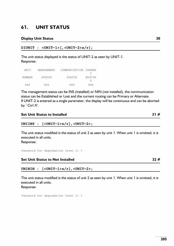
205
61. UNIT STATUS
Display Unit Status 30
DIUNIT : <UNIT-1>[,<UNIT-2>s/r];
The unit status displayed is the status of UNIT-2 as seen by UNIT-1.Response:
The management status can be INS (installed) or NIN (not installed), the communication status can be Established or Lost and the current routing can be Primary or Alternate.If UNIT-2 is entered as a single parameter, the display will be continuous and can be aborted by `Ctrl X'.
Set Unit Status to Installed 31 #
UNIINS : [<UNIT-1>s/r],<UNIT-2>;
The unit status modified is the status of unit 2 as seen by unit 1. When unit 1 is omitted, it is executed in all units.Response:
Set Unit Status to Not Installed 32 #
UNININ : [<UNIT-1>s/r],<UNIT-2>;
The unit status modified is the status of unit 2 as seen by unit 1. When unit 1 is omitted, it is executed in all units.Response:
UNIT MANAGEMENT COMMUNICATION CURRENT
NUMBER STATUS STATUS ROUTING
xxx xxx xxx xxx
Password for degradation level 2: ?
Password for degradation level 2: ?
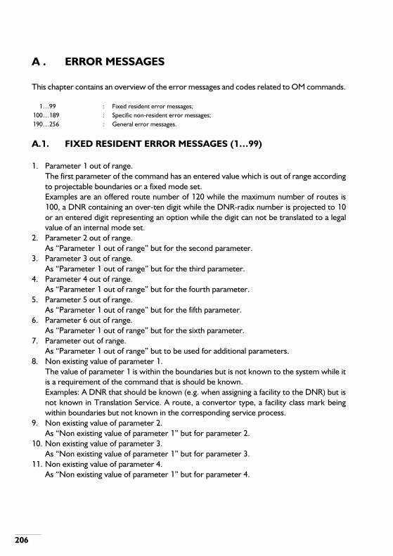
206
A . ERROR MESSAGES
This chapter contains an overview of the error messages and codes related to OM commands.
A.1. FIXED RESIDENT ERROR MESSAGES (1…99)
1. Parameter 1 out of range.The first parameter of the command has an entered value which is out of range accordingto projectable boundaries or a fixed mode set.Examples are an offered route number of 120 while the maximum number of routes is100, a DNR containing an over-ten digit while the DNR-radix number is projected to 10or an entered digit representing an option while the digit can not be translated to a legalvalue of an internal mode set.
2. Parameter 2 out of range.As “Parameter 1 out of range” but for the second parameter.
3. Parameter 3 out of range.As “Parameter 1 out of range” but for the third parameter.
4. Parameter 4 out of range.As “Parameter 1 out of range” but for the fourth parameter.
5. Parameter 5 out of range.As “Parameter 1 out of range” but for the fifth parameter.
6. Parameter 6 out of range.As “Parameter 1 out of range” but for the sixth parameter.
7. Parameter out of range.As “Parameter 1 out of range” but to be used for additional parameters.
8. Non existing value of parameter 1.The value of parameter 1 is within the boundaries but is not known to the system while itis a requirement of the command that is should be known.Examples: A DNR that should be known (e.g. when assigning a facility to the DNR) but isnot known in Translation Service. A route, a convertor type, a facility class mark beingwithin boundaries but not known in the corresponding service process.
9. Non existing value of parameter 2.As “Non existing value of parameter 1” but for parameter 2.
10. Non existing value of parameter 3.As “Non existing value of parameter 1” but for parameter 3.
11. Non existing value of parameter 4.As “Non existing value of parameter 1” but for parameter 4.
1…99 : Fixed resident error messages;100…189 : Specific non-resident error messages;190…256 : General error messages.

207
12. Non existing value of parameter 5.As “Non existing value of parameter 1” but for parameter 5.
13. Non existing value of parameter 6.As “Non existing value of parameter 1” but for parameter 6.
14. Non existing value of parameter.As “Non existing value of parameter 1” but for additional parameters.
15. Already existing value of parameter 1.The value of parameter 1 is within the boundaries but already known to the system whileit is a requirement of the command that is should not be known yet.Examples: A route, a convertor type, a cv-value etc., which is to be created, being withinboundaries but already known in the corresponding service process.
16. Already existing value of parameter 2.As “Already existing value of parameter 1” but for parameter 2.
17. Already existing value of parameter 3.As “Already existing value of parameter 1” but for parameter 3.
18. Already existing value of parameter 4.As “Already existing value of parameter 1” but for parameter 4.
19. Already existing value of parameter 5.As “Already existing value of parameter 1” but for parameter 5.
20. Already existing value of parameter 6.As “Already existing value of parameter 1” but for parameter 6.
21. Already existing value of parameter.As “Already existing value of parameter 1” but for additional parameters.
22. Parameter 1 missing.Parameter 1 is omitted while it is not allowed according to system options or previouslysuccessfully executed commands.If the parameter is omitted conflicting with the value of another parameter in the samecommand string the message “Illegal parameter combination” is used instead.Example: Parameter 1 is the unit number. This parameter may only be omitted in a singleunit-system (project dependent). In a multi-unit system then this message is generated.
23. Parameter 2 missing.As “Parameter 1 missing” but for parameter 2.
24. Parameter 3 missing.As “Parameter 1 missing” but for parameter 3.
25. Parameter 4 missing.As “Parameter 1 missing” but for parameter 4.
26. Parameter 5 missing.As “Parameter 1 missing” but for parameter 5.
27. Parameter 6 missing.As “Parameter 1 missing” but for parameter 6.
28. Illegal parameter combination.

208
This message is used when parameters within a command are related to each other. Thevalue of one parameter can exclude the value of another parameter or the value of oneparameter may require that another parameter is omitted. For cases like these it can notbe determined which parameter actually is wrong (fatal validation).This message is also used if a certain parameter is composed of several items (e.g. aparameter is a bit-stream, each bit representing an option). If one item of the parameterexcludes another item within the same parameter this message can be used. As it is knownwhich parameter is wrong this error may be non-fatal.
29. Device is write protected.An attempt is made to write to a write protected device.
30. Lack of space.This message is used as an execution error because no room is available in thecorresponding service process to add new data. In most cases it will be evident whichspecific action causes the error as most commands add only one relation at a time so thiserror message will give sufficient information.
31. No relations or data found.This message is used in commands performing a display function.Example: All abbreviated numbers are to be displayed but there are no abbreviatednumbers defined at all.
32. EHWA not in use.The elements of an entered EHWA are within the boundaries but the EHWA is not knownto the system while it is a requirement of the command that is should be known.Example: A DNR is to be assigned to an LCT but the LCT (by its EHWA) is not known.
33. EHWA already in use.The elements of an entered EHWA are within the boundaries but the EHWA is alreadyknown to the system while it is a requirement of the command that is should not be knownyet.Example: A board is to be installed at a certain position but that position (by its EHWA) isalready occupied.
34. EHWA has incorrect type.Is used for actions on a resource (entered as EHWA) while the type of the entered EHWAdoes not fit with the action.Example: A DNR is to be assigned to an LCT but the offered EHWA belongs to a trunk.
35. Incorrect status.If an action to be performed on a resource requires a certain status (NIN, OUT, etc) andthe resources does not have this status this message is used.
36. DNR has incorrect type.Used for actions on a DNR while the DNR has not the correct type (operator, group,extension).Example: An extension has to be moved but the offered DNR belongs to an operatorinstead of an extension.

209
37. Resource not assigned.Used for actions on a resource that should be assigned to a certain pool.Example: A trunk is to be removed from a bundle while it is not assigned.
38. Resource already assigned.Used for resources which are to be assigned to a certain pool.Example: Trunk lines, paging lines, paging codes to be assigned to a route while it is alreadybeen assigned before.
39. Invalid input data.The entered data in a command is conflicting with earlier entered data or data of oneparameter is conflicting with data of another parameter in the same command string.
40. Not yet implemented.Standard message to cover an action within a command which has not yet beenimplemented.
41. Restriction on action.Besides the authority class mechanism also restrictions within a command are possible. Ifwithin a command a certain action is to be performed while this action is restricted tocertain users only or not possible because of implementation reasons this message is used.Example: From a certain OM terminal it is only allowed to change only a few facility classmarks and/or traffic classesAnother example is derived from the limited possibilities of OM from the operatorconsole. For a certain action a password is required. As passwords contain characterswhich are not available at an operator console this action will not be possible (restrictedto OM terminals).
42. File specification error.File specifications are normally a concatenation of logical device name and file name (plusextension) in one parameter. Depending on the context certain characters are allowed ornot. If the parameter contains invalid characters this message is used.
43. Source file specification error.As “File specification error” but to be used in commands with more file specifications inthe same command string.
44. Destination file specification error.As “File specification error” but used in commands with more file specifications in thesame command string.
45. Logical device does not exist.File specifications are normally a concatenation of logical device name and file name (plusextension) in one parameter. First check will always be to check the parameter on invalidcharacters. If invalid characters are present the message “… file specification error” willbe used. If not, it will be checked if the logical device name part refers to an existing logicaldevice. If not this message “Logical device does not exist” is used. If the parameter is nota file specification but only a logical device name the message “Non existing value ofparameter x” is used instead.

210
46. Source logical device does not exist.As “Logical device does not exist” but used in commands with more file specifications inthe same command string.
47. Destination logical device does not exist.As “Logical device does not exist” but used in commands with more file specifications inthe same command string.
48. File open error.Execution error when accessing a file to be opened.
49. File write error.Execution error when accessing a file for writing.
50. File read error.Execution error when accessing a file for reading.
51. File delete error.Execution error when accessing a file to be deleted.
52. File close error.Execution error when accessing a file to be closed.
53. File specification incomplete.File specifications are normally a concatenation of logical device name and file name plusextension and generation in one parameter.Depending on the command one or more of these parts may be omitted.Defaults then may be used per part. If a part is omitted while no default is known thismessage is used.
54. Source file specification incomplete.As “File specification incomplete” but used in commands with more file specifications inthe same command string.
55. Destination file specification incomplete.As “File specification incomplete” but used in commands with more file specifications inthe same string.
56. Illegal password entered.Password is not correct.
57. File not found.The specified filename does not exist.
58. Source file open error.The specified (source) filename does not exist.
59. Destination file open error.The specified (destination) filename does not exist.
60. Protection level mismatch.Your protection level does not permit the requested action. See chapter 4.
61. Maximum number of open files exceeded.The maximum number of open files is reached, so it is not possible to open another one.
62. File already opened.
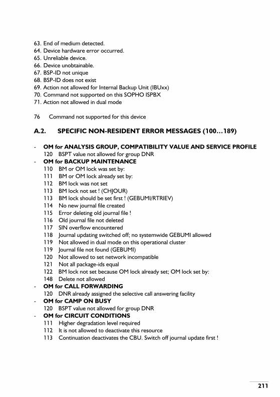
211
63. End of medium detected.64. Device hardware error occurred.65. Unreliable device.66. Device unobtainable.67. BSP-ID not unique68. BSP-ID does not exist69. Action not allowed for Internal Backup Unit (IBUxx)70. Command not supported on this SOPHO ISPBX71. Action not allowed in dual mode
76 Command not supported for this device
A.2. SPECIFIC NON-RESIDENT ERROR MESSAGES (100…189)
- OM for ANALYSIS GROUP, COMPATIBILITY VALUE AND SERVICE PROFILE120 BSPT value not allowed for group DNR
- OM for BACKUP MAINTENANCE110 BM or OM lock was set by:111 BM or OM lock already set by:112 BM lock was not set113 BM lock not set ! (CHJOUR)113 BM lock should be set first ! (GEBUMI/RTRIEV)114 No new journal file created115 Error deleting old journal file !116 Old journal file not deleted117 SIN overflow encountered118 Journal updating switched off; no systemwide GEBUMI allowed119 Not allowed in dual mode on this operational cluster119 Journal file not found (GEBUMI)120 Not allowed to set network incompatible121 Not all package-ids equal122 BM lock not set because OM lock already set; OM lock set by:148 Delete not allowed
- OM for CALL FORWARDING120 DNR already assigned the selective call answering facility
- OM for CAMP ON BUSY120 BSPT value not allowed for group DNR
- OM for CIRCUIT CONDITIONS111 Higher degradation level required112 It is not allowed to deactivate this resource113 Continuation deactivates the CBU. Switch off journal update first !

212
114 No virtual channel assigned137 Action not allowed because there are already two CCS slices masked138 It is not allowed to deactivate the local SSM-MPC139 Action not allowed because port has no logical device yet140 Last OM device may not be deactivated on this ISPBX platform186 It is not allowed to deactive shelves, modules or the CPU
- OM for COMMAND FILE EXECUTION180 Command file specification error181 Log file specification error182 Date and time not set (use SEDATI)183 Command file not found184 Log file not found185 Maximum number of jobs already submitted186 Job not submitted due to internal error; try again187 Maximum file length [4000char's] exceeded188 Incompatible command file189 Use EXSJOB for special batch files
- OM for DATA FUNCTIONS120 No expanded cv modes122 Still EHWAs for convertor type present
- OM for DIGITAL ALARMS110 Resource not in service
- OM for DISPLAY METERING120 BSPT value not allowed for operator DNR
- OM for DNR/BSP-ID - LINE CIRCUIT RELATIONS120 No space for new DNR121 DNR is not assigned122 DNR is already assigned to other EHWA123 Move not possible - too many BSPs assigned124 WARNING : EHWA now contains more than one BSP-ID!125 No space for LENR data126 No space for IABD data127 DNR is special extension128 Not all IABD numbers are transferred129 DNR or EHWA busy130 (Some) involved BSP is executive or secretary133 DNR is groupmember134 DNR already in use135 No space for BSP data136 No space for night extension data137 No space for diversion to external data

213
138 No space for executive data139 No space for hotline data140 DNR and/or BSP already assigned to given EHWA141 Incorrect BSP-ID or DNR has incorrect type142 ALL-BSPT (99) not allowed143 Maximum number of BSPs with given DNR already assigned144 BSPT does not exist145 BSP-ID already exists146 DNR has been assigned the selective call answering facility147 BSP is executive or secretary148 No space for password data149 BSPT does not contain IBSC150 Special extension is already assigned to EHWA151 No desksharing license152 Special extension may not be moved to hardware-less position153 Another Basic DNR for this unit already exists154 After this action the BSP will be not-usable155 No space for CNND data156 CNND relation not transferred157 Not all IABD numbers and CNND relations are transferred
- OM for DOWNLOAD110 Download package delete error111 No reply on delete error120 ALL-BSPT (99) not allowed121 Incorrect BSP-ID or DNR has incorrect type
- OM for EXECUTIVE/SECRETARY GROUPS120 Executive BSP-ID has incorrect type or is already assigned121 Secretary BSP-ID has incorrect type or is already assigned122 Identifying BSP-ID is incorrect123 Executive and secretary BSP-ID are not located in the same unit124 Warning: BSP-ID is assigned to other executive-secretary pool or group125 Warning: BSP-ID is not related to a feature phone126 Warning: BSP-ID is already related to a function key menu127 BSP-ID already in use128 File already present129 New command file written130 Executive and secretary BSP-ID not located within the one unit131 Group DNR is special extension140 Warning: Function key menus should be used for exec/sec group141 Number of function key menus too small142 Group property not allowed

214
144 BSP-ID already assigned the selective call answering facility145 ALL-BSPT (99) not allowed146 BSP-ID with same identifying DNR already assigned to this group147 Executive BSP-ID is already assigned as ACD group member148 Secretary BSP-ID is already assigned as ACD group member
- OM for FACILITY CLASS MARKS120 Mark is R/O or not existing or disabled on this type of DNR121 Action not allowed for this facility class mark124 Incorrect BSP-ID or DNR has incorrect type
- OM for FILE MANIPULATION140 Directory file not found141 Directory file open error142 Directory read error143 Source file read error144 Copy read error > Check presence of incomplete destination file !145 Copy write error > Check presence of incomplete destination file !146 Delete not allowed147 Binary files may not be typed148 Delete not allowed
- OM for FOLLOW ME151 Originator is not follow me entitled152 Destination is follow me protected153 Action currently not allowed154 ALL-BSPT (99) not allowed
- OM for FUNCTION KEYS AND MENUS120 ALL-BSPT (99) not allowed132 Key-data indicates park position: led code not allowed133 Key-data indicates executive line position: wrong led code134 Key-data indicates executive line position: led code missing135 Function_key/level doesn't allow key-data for park/line position136 Series/range not allowed for function key or level when assigning data137 Key-data indicates automatic transfer: wrong led code138 Key-data indicates automatic transfer: led code missing139 Function key doesn't allow key-data for automatic transfer
- OM for GENERAL CANCEL CODE120 Result-id not allowed for general cancel code
- OM for GROUP ARRANGEMENTS120 Group DNR and/or member BSP-ID are special extension DNR121 Group has no ACD property (DIGRPS)121 Member BSP-ID has incorrect type or is already assigned (CRGRPA/ASGRPM)122 No-member group not allowed

215
123 DNR already in use124 Member BSP-ID cannot be switched to absent125 Still follow me relation present126 Still call forwarding relation present127 Park/line position only allowed in non ACD group128 Option F of extended properties may only be set for ACD groups129 DNR not found130 BSP-ID already assigned the selective call answering facility131 A no-member group may not be switched to Day status132 BSP-ID with same identifying DNR already assigned to this group133 BSP-ID or DNR does not exist134 ALL-BSPT (99) not allowed135 Member with same DNR already assigned to group with same supervisor136 Member BSP-ID is already assigned as executive137 Member BSP-ID is already assigned as secretary138 No space for new ACD group member139 DNR has incorrect type or group has no ACD property140 No logical device assigned due to lack of space141 No more members allowed in Multiple Ring Group142 Group DNR and member BSP-ID are not located in the same unit143 No space for member or group assignment
- OM for HARDWARE CONFIGURATION109 Still dongle in overlay with VDU present110 Not allowed circuit number at board111 Action not allowed when journal updating switched ON !112 Still boards in shelf present113 The sequence number is invalid114 Still links present115 Still devices present116 Still bundle-DTU relations present with bundle117 Still a DNR present118 Still line-route relations present119 Still line-bundle relations present120 Still special extension relations present121 Still D-channel relation present122 Still CRU-entry present123 Still main-slave board relation present124 Not allowed to delete last LDN125 Still LDN relations present (DEDEVC)125 Still tone sources present (DEBRDS)126 Still boards controlled by this board present

216
127 Port occupied by B-channel of adjacent ISDN bus128 A port, required for B-channel, is already in use129 Different PCT-types not allowed at same bus130 Module controller board is already present131 PMC-MC-PRIMARY board may not be deleted132 CSN-BC board may not be deleted133 Only one remote port allowed in unit134 Board not yet assigned135 Illegal link combination136 Link can not be deleted137 This fixed device may not be deleted138 Device name or type incorrect or not allowed for this port139 Link type not allowed140 Device not known as local device in unit (ASLDNM)140 Link circuit number out of range (ASLINK/DELINK)141 Still remote PM or Interunit link present in local PM142 First CSN-PMC link has to be assigned to local PM143 Still device ports present144 First assign the SNS board(s) with lower EHWA145 First assign the SNS board(s) with higher EHWA146 Conflict between equipment type and LDN147 Not allowed to delete circuit149 LBU and DBU may not be deleted on this ISPBX150 Device not known as local device in unit151 Not all requested virtual circuits is assigned152 Equipment type not supported on this SOPHO ISPBX160 This link can not be assigned as a controllable link161 Board not yet assigned162 Controller board not yet assigned163 Link incompatible with board164 Device incompatible with board165 Assign the controllable links to this destination first166 Delete the not controllable links to this destination first167 Still PCH resources in use168 Not enough PCH resources available169 Incorrect board position170 Main board not present171 DTU-CC not used in interunit link172 DTU-CC already used in link173 Parameter NVCT not allowed for given EHWA174 Value for parameter 4 is not allowed on this ISPBX platform

217
175 Board is not an SCU board176 Link assigned, but due to lack of space no or not all ILCs (ASLINK)176 Not all requested virtual circuits assigned (ASBRVC)177 Inconsistent data detected in HCA178 Shelf not yet assigned179 DTU already used with other CRU-entry180 Still virtual circuits present181 Still convertor present182 Change board subtype not allowed for this board183 Board of circuit is not yet assigned184 Not allowed; use assign/delete board command185 No related board characteristics table found187 Board is not a PMC-MC-MASTER board188 Board is not a CSN-BC189 Board is not a PMC board
- OM for IABD AND LENR FACILITIES120 DNR has no IABD and LENR FACM assigned
- OM for INITIALISE DISK140 It is not allowed to initialise a CBU141 Device no storage device142 Command currently not allowed. Files open on device, try again.
- OM for INTEGRATED ANNOUNCEMENT SYSTEM121 Group has no ACD property
- OM for INTER UNIT TRUNK TRAFFIC120 Bundle already assigned121 Bundle not assigned to route
- OM for MANAGER DATA120 BSPT value not allowed for operator DNR
- OM for MERCURY INDIRECT SERVICE120 Old authorization code validation error121 New authorization code verification error
- OM for MISCELLANEOUS DNR ACTIONS120 No local CNND database defined
- OM for MULTIPLE SUBSCRIBER NUMBER120 Not allowed to change MSN parameters of a DCC circuit
- OM for NIGHT TRAFFIC AND SPECIAL EXTENSIONS121 DNR already assigned the selective call answering facility122 Already other special extension type assigned to trunkline123 Special extension type incorrect124 DNR is member of special extension group125 DNR is group with special extension member

218
- OM for NUMBERING SCHEME120 Barring mark set121 Number already barred
- OM for OVERLAY MODULES140 Overlay not found141 Delete not allowed142 Delete postponed until the overlay is unused143 Delete request pending144 No loading space available in memory145 CM device error146 Error in overlay found147 Action not allowed for permanent overlays
- OM for PAGING121 Unit already assigned to a paging area122 Unit is utility unit123 Still routes assigned to area124 Still virtual codes assigned to route125 Still lines assigned to route135 Route has incorrect type
- OM for PASSWORD PROTECTED FACILITIES120 Password relation not found121 PID/CC not found122 PID/CC already assigned123 PID/CC `999999' is reserved for malicious call trace
- OM for PRIVATE VIRTUAL NETWORKING120 Old security code validation error121 New security code verification error137 Signalling Channel busy138 UCA busy139 RIN already assigned to a signalling channel140 PVN route is not a Main route
- OM for PROJECTING110 Data rejected by service process140 PM (being) activated141 Downloading active
- OM for REMOTE MAINTENANCE100 The new configuration is stored110 Either RMAIN0.CNF or RMAIN1.CNF should be used111 A new configuration file RMAINx.CNF is written (x=remote usergroup)112 No new configuration file is written113 Not allowed to clear this item

219
- OM for SYSTEM DUMP140 No system dump present141 Dump already present142 Writing system dump initiated143 Writing system dump already in progress144 System dump erased
- OM for SYSTEM SECURITY110 Old password validation error111 New password verification error (CHPASS)111 Unknown OM terminal (CHDEAU/CHDEPR/DIAUPR)120 Authority class index 0..15 can not be changed121 Authority class value 15 is not allowed122 No value has been found, given index not known
- OM for TESTING100 Request already present101 Request not found110 B-channel not available for test (CRCCSP/CRCCPP)110 Test already in progress for this resource (DIMEMQ)111 Error during release of the controlled connection (ERCOCO)111 Test aborted by operating system - try again after a few minutes (DIMEMQ)112 The current controlled connection state does not allow this command113 The digits received are already monitored114 No digit receiving resource involved in this controlled connection115 No digit sending resource involved in this controlled connection116 No tone sending resource involved in this controlled connection117 Controlled connection rolled back118 Maximum number of controlled connections exceeded119 No tone resources allowed in paired path controlled connections120 Controlled connection erased121 Error during flow establishment122 No pulsed sending resource125 Incompatible resource status
- OM for TOLL TICKETING AND FULL DETAILED CALL RECORDING110 FDCR facility not active111 Toll Ticketing facility not active
- OM for TRAFFIC OBSERVATIONS AND MEASUREMENT110 Traffic measurement not started: already active111 Traffic measurement inconsistency112 No figures available; data currently being gathered113 Figures not yet available120 ALL-BSPT (99) not allowed

220
121 BSPT value not allowed for group DNR122 BSPT value not allowed for operator DNR
- OM for TRAFFIC CLASSES120 BSPT value not allowed for operator DNR
- OM for TRUNK TRAFFIC120 Bundle already assigned122 BSPT is not assigned123 BSPT not known in system124 BSPT already assigned125 BSPT not unique (IBSC overlap)126 Some B-channels in this circuit already assigned to other bundle127 BSPT invalid or not assigned128 Still SCNE or overflow extension assigned to route129 Still bundles assigned to route130 Still PVN data assigned to route (ERROUT)130 Trunk/bundle incompatible with involved EHWA(s) (CHBNDC/ASLINE)131 No lines allowed in a PVN bundle132 Signalling-type of bundle and route mismatch133 Original number is conflicting with an already defined conversion134 Invalid input data - too many parameter characters136 Bundle not in specified route141 No space for FTLD data142 FTLI already assigned to other trunk line143 Special extension assigned to trunk line144 No bundle-route relations present145 Trunk line type does not support FTLI/FTLD facility146 Incorrect number of inc-options (non-DDI : 6, DDI : 10)147 Incorrect number of tone-and-ddi-optons (non-DDI : 2, DDI : 9)148 Tree not allowed for non-DDI149 Incorrect number of options (must be : 4)
- OM for UNIT STARTS110 A hotstart is not yet possible111 A MIS-file is required to execute a coldstart112 A hotstart is not allowed113 Not all slices synchronous114 File CONDUA.POM not present on DBU115 System already in dual mode116 System not in dual mode117 Not allowed on this cluster118 BM lock not set119 Cluster not operational
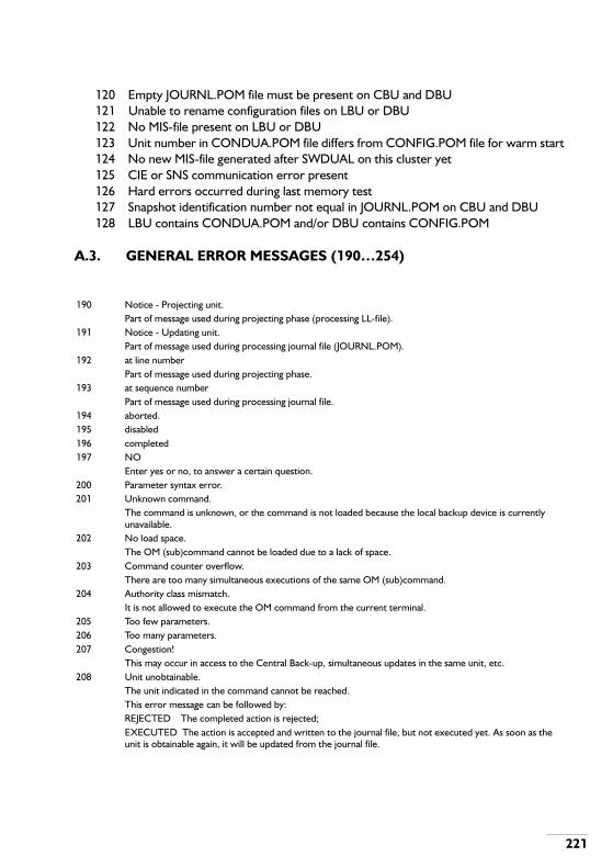
221
120 Empty JOURNL.POM file must be present on CBU and DBU121 Unable to rename configuration files on LBU or DBU122 No MIS-file present on LBU or DBU123 Unit number in CONDUA.POM file differs from CONFIG.POM file for warm start124 No new MIS-file generated after SWDUAL on this cluster yet125 CIE or SNS communication error present126 Hard errors occurred during last memory test127 Snapshot identification number not equal in JOURNL.POM on CBU and DBU128 LBU contains CONDUA.POM and/or DBU contains CONFIG.POM
A.3. GENERAL ERROR MESSAGES (190…254)
190 Notice - Projecting unit.Part of message used during projecting phase (processing LL-file).
191 Notice - Updating unit.Part of message used during processing journal file (JOURNL.POM).
192 at line numberPart of message used during projecting phase.
193 at sequence numberPart of message used during processing journal file.
194 aborted.195 disabled196 completed197 NO
Enter yes or no, to answer a certain question.200 Parameter syntax error.201 Unknown command.
The command is unknown, or the command is not loaded because the local backup device is currently unavailable.
202 No load space.The OM (sub)command cannot be loaded due to a lack of space.
203 Command counter overflow.There are too many simultaneous executions of the same OM (sub)command.
204 Authority class mismatch.It is not allowed to execute the OM command from the current terminal.
205 Too few parameters.206 Too many parameters.207 Congestion!
This may occur in access to the Central Back-up, simultaneous updates in the same unit, etc.208 Unit unobtainable.
The unit indicated in the command cannot be reached.This error message can be followed by:REJECTED The completed action is rejected;EXECUTED The action is accepted and written to the journal file, but not executed yet. As soon as the unit is obtainable again, it will be updated from the journal file.

222
209 Illegal multiple value.A parameter is entered as a series or range when this is not allowed.
210 Notice -.Header when the system generates information to the user, which is not an error indication.
211 Input line discarded.Used after Ctrl-X from an OM terminal.
212 Question mark at illegal position.213 Unit currently locked.214 Line too long.215 Time out.216 Illegal multiple value combination.
An example is a range command with the second value smaller than the first: 50&&10. This is not allowed.217 Too many parameter values.218 Parameter value too long.219 No colon at position 7 encountered.220 Device error.221 Error in overlay.
The overlay contains a checksum error and is therefore not a loadable set, or the package ID of the overlay is not conform the package ID of the system.
222 Command aborted.223 Illegal multiple command.
It is not allowed to execute the command as a multiple command.224 Enter new value.225 Non-convertible parameter.226 Execution completed.228 Open error.229 END;230 Message.231 No guidance text available.232 aborted : Log-file open error.233 aborted : Log-file write error.234 See Maintenance manual.235 END OF DIALOGUE #236 Error.237 REJECTED.238 EXECUTED.239 Job240 Unit241 finished executing242 Unit updating.
During execution of an OM command a unit is met which is not up to date. The result can be:-Unit updating + EXECUTEDThe command is accepted and written to the journal file. Execution is postponed because the unit is
updating.-Unit updating +automatic retryThe command is not yet accepted and not written to the journal file. First a validation must be done in the
unit which is not up to date. Depending on this validation the command will be rejected or journalled and executed.

223
243 First value in range bigger than second value.244 Empty parameter value.245 Press; to continue or CTRL X to abort guidance.246 Comma or ampersand in parameter repair input.247 Parameter value too short.248 Backup update error.249 Backup congestion.250 Backup unobtainable.251 Unit not installed.
A local data updating action is attempted in a unit which is not installed.252 Backup maintenance currently locked.
All OM actions that are normally written to journal file are currently disabled. This situation is the result of the execution of OM command BMLOCK. BMLOCK might be set because a MIS-file or a Retrieve-file is to be made.
253 YESA question will be put on the OM terminal screen if you have to confirm the continuation of a certain action. You can only enter yes (complete the action) or no (abort the action).
254 Operational maintenance currently locked.All OM actions that are normally written to journal file and executed from an OM device, are currently disabled. OM actions initiated from an extension (e.g. when desksharing is executed) remain possible and are written to the journal file. This situation is the result of the execution of OM command OMLOCK. OMLOCK might be set to temporary disable all OM actions which change PBX configuration data.

224
B . PARAMETERS

225
A
A-QUEUERouting to operator A-queue (1…16)
ABSDisplayed value, indicating the number of operators absent.
ABS-POMDisplayed value, indicating the number of operators absent and in OM mode.
ABBR-NUMBERAbbreviated number (1…6 digits)
ACAuthorization code for Mercury smart box emulation (2…20 digits).
ACC-REPAccess code repetition counter (0…6)
ACD-TIME-PERIODACD timer (used for various purposes)0 = 0 seconds1 = infinite2 = 5 seconds3 = 10 seconds4 = 15 seconds5 = 20 seconds6 = 25 seconds7 = 30 seconds8 = 40 seconds9 = 50 seconds10 = 1 minute11 = 2 minutes12 = 5 minutes
ACD-THRESHOLDACD group dynamic COB threshold per 100 present and IN-SERVICE group members.
ACI/FLAG

226
Authority Class Index or in the case of a MIS file the validity flag: (v=valid, i=invalid)
ACTION-INDICATORUp to SSW 805.28 the syntax of the indicator is: P.As from SSW 805.28 the syntax of the indicator is: P[Q]P = IABD/CNND-INDIndicates if an inter unit move is continued when there is not enough space for the IABD numbers and/or CNND relations belonging to the DNR in the destination unit:0 = abort (default)1 = continueQ = ORDER-INDIndicated whether the BSP-ID must be inserted in the BSP list before or after any existing BSP with the same value.0 = insert after (default)1 = insert before (used e.g. for desksharing)
ADD-INFO-NBR-LENGTHOne or two digits in the range of 0...20 indicating the number of additional info digits to be given. If the parameter is omitted, it is assumed that no additional info digits have to be given.
ADD-OR-DELETEAction parameter (0 = delete, 1 = add)
AGAnalysis group (0…254)
ALL-CALLSNumber of allowed calls in the bundle for a given BSPT (0…254).
ALLOWEDOM terminal is (not) allowed to execute commands of the assigned authority class (0 = not allowed (default), 1 = allowed)
AnA-queue number (1…16) 1 = A1 to 16 = A16 (general)
ANN-DDI-FAILAnnouncement DDI fail option:0 = Call to busy party1 = Dialling time out2 = Call to a non-allocated number

227
3 = Other unsuccessful calls
ANN-NOAnnouncement number (0…254)
ANNOUNCEMENT-CODE0…255; In some messages TMS will send an equipment number (60…79), indicating a tone source to which the subscriber should be connected. This equipment number is defined in the appropriate TMS *.PDT files.
ANNOUNCEMENT-SOURCE0 or empty erases the relation1 = Synchronous announcer specified by a DNR2 = Tone announcer specified by a tone-function number3 = Continuous announcer specified by an EHWA
ANN-PAUSE-TONEPause tone for ACD groups:0 = COB tone1 = External ring tone2 = Internal ring tone3 = MOH4 = Music on COB5 = Silence
ANN-SELECTIONAnnouncement selection on incoming trunks (0…7):0 = DDI fail calls1 = Successful DDI calls2 = Non-DDI calls (including PLE, INE, MCNE, SCNE and CANS)3 = Calls to operator A-queue4 = Station calls for ACD group5 = Night announcement for ACD group6 = Delay message for ACD group7 = Music on hold
APPLICATIONApplication identification16 = CallManager keyboard17 = CallManager display20 = General OM keyboard 1

228
21 = General OM display 122 = General OM keyboard 223 = General OM display 2
APPLICATION-VERSION1 or 2 in the case of the CallManager (default 1);2…9 in the case of general OM (default 2).
AREAPaging area number (0… 13)
AS-PCTSIndication whether the circuits on boards should be assigned automatically or not. Only valid if BOARD-TYPE is 0…69.(0 = manual, 1 = automatic)
ASSB-channel assigned yes or no.
ASSIST-GROUPAssistance group (1…15)
ASSIST-GROUP-PROPSAssistance group properties(P)P= Operator monitoring (0 = off, 1 = on).
ASSISTANCE-POINTIndicates in which exchange operator assistance should be given (1…12 digits). This can be:
- Network DNR or Cluster identify of the own exchange (local assistance).- Network DNR or Cluster identity of another exchange (external assistance).- Nothing (Source assistance).
ATFAutomatic trunk find0 = No ATF1 = ATF by camp on busy (COB)2 = ATF by automatic ring back (ARB)
AUTHORITYAuthority class (0…15). Authority classes have the following meaning:

229
0 = Display functions for the customer1 = Change telephony functions by customer2 = Change complex and data functions by customer3 = File management4 = Batch jobs5 = Change of service conditions6 = Maintenance level 17 = Maintenance level 28 = Maintenance level 39 = Second line maintenance tools10 = Spare (user definable)11 = Spare (user definable)12 = Spare (user definable)13 = Spare (user definable)14 = Change session authority class && protection (always allowed)15 = Subcommands (never allowed)
AUTHORITY-INDEXAuthority Class Index.Numeric identification of an OM command
AUTOAutomatic writing of system dump information to the local backup(See also parameters DUMP and WRITE-SEL):0 = Automatic writing disabled (default for DUMP = 2, WRITE-SEL = 0 current segment)1 = Automatic writing enabled (default for DUMP = 0, 1 or 3, WRITE-SEL = 1 all data)

230
B
B-BUTTONB button id (1…4)
B-CHANNELRelative B-channel number within the circuit. Only valid for ISDN.
BAUDRATECommunication speed (in Bauds) which is used on the port:8 = 120010 = 240012 = 480014 = 960017 = 1920018 = 38400
BCH-VALUERelative B-Channel (0…31) (if DED-TYPE is 0…2) or number of B-channels (if DED-TYPE is 3…5)
BIT/BYTEIndicating a bit (0) or a byte (1).
BOARD-TYPEBoard type, see Appendix C.
BRDisplayed parameter, indicating if the dialled destination is barred or not.
BRDBoard position in shelf (1…29).
BRD-STYPEThe sub type of the board. This is an arbitrary number given to a board, to distinguish between several boards of the same type (0…99)
BSP-IDBasic Service Profile Identification. This parameter is used instead of parameter DNR. It consists of a DNR and a BSPT, separated by a hyphen (-):

231
<DNR>[-<BSPT>]The -<BSPT> may be omitted when there is only one BSPT present on the DNR.
BSPTBasic Service Profile Type (0…99).Indicates for which BSPT the data must be changed. 99=change for all BSPTs.Table B-1 Basic Service Profile Type (BSPT).
BUDGETValue to add to/subtract from the budget or the value to set the budget to. The range is 0 ... 999999.
BSPT IBSC PRIORITY DESCRIPTION
0 0 1 64 kBit/s unrestricted1 1 1 Speech2 2 1 3.1 kHz audio3 3 1 3.1 kHz audio non-ISDN4 4 1 7 kHz audio5 5 1 Teletex6 6 1 Telefax47 7 1 Mixed mode8 8 1 Videotex9 9 1 Slow scan television
10 10 1 Fernwirken11 11 1 GrafikTelefon12 12 1 Bildschirmtext13 13 1 Bildtelefon Bild14 14 1 SOPHO ISPBX speech15 15 1 SOPHO ISPBX modem data16 16 1 X.2117 17 1 X.2518 18 1 Bildtelefon Ton19 19 1 64 kBit/s unrestricted non-ISDN
20…93 User definable 2 Free for use (CRBSPT command)94 0, 2, 3, 4, 5, 6, 7, 8, 9, 10, 11, 12, 13,
15, 16, 17, 192 Data / possibly data
95 1, 3, 4, 14, 18, 19 2 Voice / possibly voice96 0, 2, 5, 6, 7, 8, 9, 10, 11, 12, 13, 15, 16,
173 Data
97 1, 14, 18 3 Voice98 0, 1, 2, 3, 4, 5, 6, 7, 8, 9, 10, 11, 12, 13,
14, 15, 16, 17, 18, 194 Any (Default)
99 All BSPTsNote: On a route only one BSPT with priority 2 is allowed.
Not all ISDN services (BSPTs) might be supported by the public exchange.

232
BUDGET-ACTION0 = subtract from the budget1 = add to the budget2 = set budget to amount
BUDGET-UNITUnit number where the budget is stored (1 ... 14).
BUNDLEBundle number (0…254)
BUNDLE-DIRDirection of a bundle:0 = incoming1 = outgoing2 = bothway.

233
C
C-BUSYDisplayed value, indicating the number of busy calls in the C-queue.
C-PREDisplayed value, indicating the number of preferent calls in the C-queue.
C-RINGDisplayed value, indicating the number of ringing calls in the C-queue.
C-SERDisplayed value, indicating the number of series calls in the C-queue.
C-TAXDisplayed value, indicating the number of taxmetering calls in the C-queue.
CC-TABLENumber of the CLI or COL translation table (0...254).
CFDA-TIMECall Forwarding on Don't Answer time in seconds (5...254 sec).
CF-TYPEType of call forwarding:0 = call forwarding on don't answer1 = call forwarding on busy2 = call forwarding on absent group member3 = call forwarding on empty group4 = call forwarding on group overflow5 = call forwarding on group in night service6 = call forwarding on not existing DNR (from SSW 805.21)7 = call forwarding on out of order extension (from SSW 805.21)8 = call forwarding on not reachable extension (from SSW 805.24)
CHARGED0 = toll free1 = charged (default)
CLUSTER-ID

234
The identity of the SOPHO system (cluster) for use with DPNSS (1…6 digits, each 0…9)
CnC call type:0 = Not answered1 = unsuccessful2 = Not on hook3 = On hook4 = Series5 = Taxmetering6 = Through connection busy7 = Preferred call8 = Through connection ringing
COB-QUEUE-TYPELength definition for the Camp On Busy queue. Three types:0 = No COB queue1 = Short COB queue2 = Long COB queue
COCO-NUMBERControlled Connection Number.This is a unique number for each controlled connection for test purposes. It must be in the range 1…99.
COMMAND-FILECommand file specification consisting of:[LDN:]FILE-NAME[.EXTENSION[.GENERATION]]If GENERATION is omitted, the latest generation is used.If EXTENSION is omitted, COM is used.If FILE-NAME is omitted, SUBMIT is used.If LDN is omitted, LBUxx is used, in which xx represents the unit number in which the job was submitted.
CON-ALLOWANCEConnection allowance:0 = Not possible1 = Not allowed2 = Allowed only with convertor3 = Allowed

235
CON-AND-SIG-TYPEBundle connection and signalling type Y[Z]ZY represents the connection type:0 = Four wire tie line1 = Two wire PSTN line2 = Two wire tie line3 = Digital PSTN line4 = Digital tie line5 = Virtual connectionZZ represents the signalling type:
* Hotline: the destination of incoming calls at any trunk in the bundle is fixed by Incoming digit conversion (as from SSW805.23).
CONDITIONService condition:0 = INS1 = OUT2 = OUT-ac3 = ABL-er4 = ABL-er-ac5 = ABL-nu6 = ABL-te7 = ABL-te-ac
INCOMING: OUTGOING:
0 = impulse impulse1 = keytone/KT sensitive impulse2 = keytone keytone3 = MFC keytone4 = hotline* impulse5 = keytone after answer keytone6 = DPNSS-x DPNSS-x7 = DPNSS-y DPNSS-y8 = MFP MFP9 = MF Socotel MF Socotel
10 = DASS DASS11 = MFE MFE12 = hotline* keytone13 = MFC-CSS1 MFC-CSS114 = ISDN-A ISDN-A15 = ISDN-B ISDN-B16 = DPNSS-PVN DPNSS-PVN

236
8 = ABL-deac9 = ABL-fail10 = ABL-hot11 = NIN
CONNECTION-TYPEIf the BCS protocol is used (PROTOCOL-TYPE), this parameter determines whether modems are used or not (0=no, 1=yes).
CONTROL-SIDEIndicates from which side a link is controlled 0 = MIC0 (for CPS)1 = MIC1(for CPS)
CONV-NUMBERConverted DNR, indicating the result string after conversion
CONVERTOR-TYPEConvertor type (0…254)
CRE-DATE/TIMECreation date and time of a file.
CRTCircuit number (0…54)
CRUE-BRDBoard position of the clock entry
CRUE-CRTCircuit number of the clock entry
CRUE-SHELFShelf number of the clock entry
CURCurrent authority class value.
CVCompatibility value (0…254)

237
CYCLICCyclic or once (0 = cyclic, 1 = once)

238
D
DATAThe contents of the BIT (0...1)/BYTE (0…255).
DATA-INDICATORThis indicator specifies the kind of data:0 = Load in permission units1 = Number of tasks running2 = Guaranteed load in %3 = Maximum load in %4 = Minimum load in %5 = Maximum number of tasks allowed6 = Timeout value in minutes
DATEAbsolute date in the form YYYY-MM-DD or relative date in the form +dddd (number of days)
DAYDay of the month (1…31)
DAY/NIGHTDay or Night indication for ACD groups (0 = Night, 1 = Day)
DAY-OF-WEEKDay of week (1…7). Normally Monday is day 1.
DAY-TRFCTraffic class during day time (see TRFC)
DED-TYPEDedication type (0…5):
- If DED-TYPE is 0…2 (1TR6/Euro-ISDN):The dedication mode of a specific B-Channel:0 = Set B-Channel dedication incoming1 = Set B-Channel dedication outgoing2 = Set B-Channel dedication bothway
- IF DED-TYPE is 3…5 (VN2):The maximum number of calls in the access:

239
3 = Set maximum number of incoming calls4 = Set maximum number of outgoing calls5 = Set maximum number of calls
DEFDefault authority class value.
DELAYDelay mark (0 = no, 1 = yes)
DESCRIPTIONA description of the function of the file.
DESTNumber of the destination (0…254).
DEST/NUMBERNumber of the destination (0…254), in Numbering scheme this can also be a paging route (0…254). In the case of PVN result-id's this can also be a unit number and for desksharing it is the validation type.
DEST-NUMBERDestination number for Follow Me, Hot Line, Twinning and Call Forwarding types 0…5 (1…20 digits) and 6 and up (1…8 digits for CPS and 1…20 digits for CCS.
DEST-BRDBoard identification of destination. See BRD.
DEST-CC-STRINGTranslated CLI or COL string : max. 16 digits, the string may end in wildcards (%).
DEST-CRTCircuit identification of destination. See CRT.
DEST-SHELFShelf identification of destination. See SHELF.
DESTINATION-FILEDestination file specification. See FILE.
DFP-INDICATOR

240
Digit, frequency or pulsed indicator(0 = digit, 1 = frequency, 2 =pulsed).
DIALTONE-PLACEPlace in the digit string (<MAX-LENGTH) where second dial tone is generated (1…19, 0=no second dialtone)
DIAL-TYPEDial type0 = Extension1 = Enquiry2 = Operator3 = Post4 = Alternative destination5 = FM primary6 = Pickup destination7 = Executive secretary8 = Overlay time out dialling9 = Overlay continue dialling
DIGITThe given digit will be used as fixed MSN digit when the MSN type of the EHWA to which the BSP is assigned is `MSN with fixed digit'.
DIGIT-ASSISTPaging mode digit for assisted transit calls (keyed numeral)
DIGIT-EXTPaging mode digit for external originated calls (keyed numeral)
DIGIT-INTPaging mode digit for internal originated calls (keyed numeral)
DIGIT/FREQDepending on DF-INDICATOR: Digit (0…15) or a frequency (0…6).The control frequency is 6.
DIGIT-POSITIONTMS digit position (1…20). This indicates the place where TMS (SystemManager) expects the service code in a dialled string.

241
DIR-AND-NEGBundle direction and ISDN negotiation: P[Q]
DIRECTORY-TYPEDirectory typeS = System directory layout (default)U = User directory layoutD = Description directory layout
DNRDirectory number (1…6 digits). It is possible to use leading zero's (0) until a projectable digit is encountered. See FIM-Voice Explained, chapter 1, “Hardware Relations”.
DOWN-TRFCDowngraded traffic class (see TRFC).
DSDisplayed parameter, indicating the destination of a call.
DTDisplayed parameter, indicating the dial tone place.
DTU-BRDBoard location of the DTU
DTU-SHELFNumber of the shelf in which the DTU is located
DUMPCause of the system dump (0…3):0 = A frozen process1 = An operational start due to a software exception2 = An operational start due to a manual request3 = A trigger to gather diagnostical data
DUMP-ACTION
P = Bundle direction : Q = ISDN negotiation rule :0 = Incoming 0 = Any B-channel1 = Outgoing 1 = Exclusive B-channel2 = Bothway 2 = Preferred B-Channel

242
System dump action (0…1):0 = Set dump trigger1 = Reset dump trigger
DURATIONThreshold of call duration in seconds (max 4 digits).

243
E
EQUIPMENT-TYPEType of the device:0 = Non OM keyboard (Lab usage)1 = Non OM display (Lab usage)4 = Disc not tested (obsolete)5 = Toll ticketing7 = Solid State Backup Device (CPS only)11 = MIS output13 = Fixed alarming (CCS only)14 = OM keyboard DND Nolog15 = OM display DND Nolog16 = OM keyboard CallManager17 = OM display CallManager18 = OM keyboard ACD90 (not for CCS)19 = OM display ACD90 (not for CCS)20 = OM 1 keyboard21 = OM 1 display22 = OM 2 keyboard23 = OM 2 display24 = Printer25 = FDCR (ASCII output)26 = Disk Emulator27 = Alarm signaller28 = Alarm unit (CPU-ME/MT only)29 = SOPHO SystemManager services30 = Dongle read31 = Dongle write32 = FDCR (binary) (binary output)
EXCLExclusivity mark (0=no, 1=yes).The exclusivity mark is used when the access in connected to a test device. The system will not accept or make calls to any B-channel in this access.
EXEC-BSP-IDExecutive BSP-ID (see BSP-ID)
EXEC-RANK
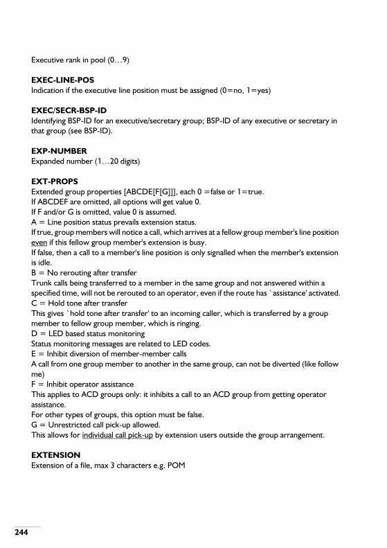
244
Executive rank in pool (0…9)
EXEC-LINE-POSIndication if the executive line position must be assigned (0=no, 1=yes)
EXEC/SECR-BSP-IDIdentifying BSP-ID for an executive/secretary group; BSP-ID of any executive or secretary in that group (see BSP-ID).
EXP-NUMBERExpanded number (1…20 digits)
EXT-PROPSExtended group properties [ABCDE[F[G]]], each 0 =false or 1=true.If ABCDEF are omitted, all options will get value 0.If F and/or G is omitted, value 0 is assumed.A = Line position status prevails extension status.If true, group members will notice a call, which arrives at a fellow group member's line position even if this fellow group member's extension is busy.If false, then a call to a member's line position is only signalled when the member's extension is idle.B = No rerouting after transferTrunk calls being transferred to a member in the same group and not answered within a specified time, will not be rerouted to an operator, even if the route has ̀ assistance' activated.C = Hold tone after transferThis gives `hold tone after transfer' to an incoming caller, which is transferred by a group member to fellow group member, which is ringing.D = LED based status monitoringStatus monitoring messages are related to LED codes.E = Inhibit diversion of member-member callsA call from one group member to another in the same group, can not be diverted (like follow me)F = Inhibit operator assistanceThis applies to ACD groups only: it inhibits a call to an ACD group from getting operator assistance.For other types of groups, this option must be false.G = Unrestricted call pick-up allowed.This allows for individual call pick-up by extension users outside the group arrangement.
EXTENSIONExtension of a file, max 3 characters e.g. POM
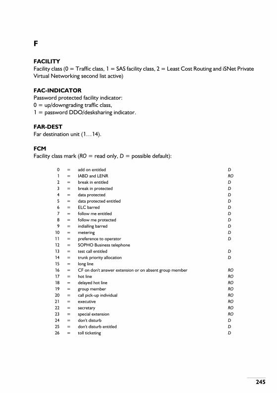
245
F
FACILITYFacility class (0 = Traffic class, 1 = SAS facility class, 2 = Least Cost Routing and iSNet Private Virtual Networking second list active)
FAC-INDICATORPassword protected facility indicator: 0 = up/downgrading traffic class,1 = password DDO/desksharing indicator.
FAR-DESTFar destination unit (1…14).
FCMFacility class mark (RO = read only, D = possible default):
0 = add on entitled D1 = IABD and LENR RO2 = break in entitled D3 = break in protected D4 = data protected D5 = data protected entitled D6 = ELC barred D7 = follow me entitled D8 = follow me protected D9 = indialling barred D
10 = metering D11 = preference to operator D12 = SOPHO Business telephone13 = test call entitled D14 = trunk priority allocation D15 = long line16 = CF on don't answer extension or on absent group member RO17 = hot line RO18 = delayed hot line RO19 = group member RO20 = call pick-up individual RO21 = executive RO22 = secretary RO23 = special extension RO24 = don't disturb D25 = don't disturb entitled D26 = toll ticketing D
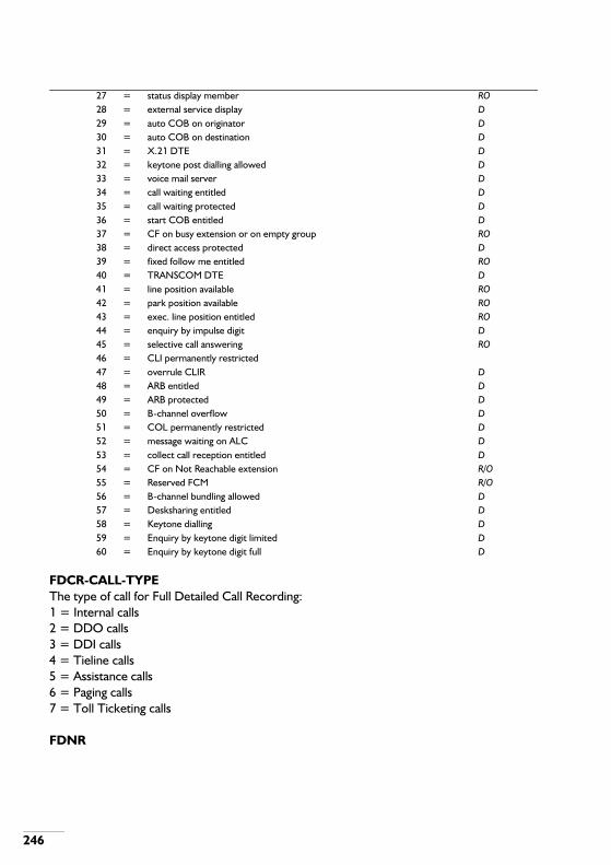
246
FDCR-CALL-TYPEThe type of call for Full Detailed Call Recording:1 = Internal calls2 = DDO calls3 = DDI calls4 = Tieline calls5 = Assistance calls6 = Paging calls7 = Toll Ticketing calls
FDNR
27 = status display member RO28 = external service display D29 = auto COB on originator D30 = auto COB on destination D31 = X.21 DTE D32 = keytone post dialling allowed D33 = voice mail server D34 = call waiting entitled D35 = call waiting protected D36 = start COB entitled D37 = CF on busy extension or on empty group RO38 = direct access protected D39 = fixed follow me entitled RO40 = TRANSCOM DTE D41 = line position available RO42 = park position available RO43 = exec. line position entitled RO44 = enquiry by impulse digit D45 = selective call answering RO46 = CLI permanently restricted47 = overrule CLIR D48 = ARB entitled D49 = ARB protected D50 = B-channel overflow D51 = COL permanently restricted D52 = message waiting on ALC D53 = collect call reception entitled D54 = CF on Not Reachable extension R/O55 = Reserved FCM R/O56 = B-channel bundling allowed D57 = Desksharing entitled D58 = Keytone dialling D59 = Enquiry by keytone digit limited D60 = Enquiry by keytone digit full D

247
Free Number : a digit string consisting of 1 to 6 digits (determined by boundary 307). The digits must be elements out of the digit set 0 ... 9, *, #, A, B, C. The parameter can be a complete DNR or the first digits of a range of DNRs.
FIGURE-TYPEIndication of the traffic measurement figures that are required:0 = last quarter hour figures1 = cumulative figures
FILEFile specification consisting of:LDN:FILE-NAME.EXTENSION[.GENERATION]
FILE-NAMEFile name (1…6 alphanumeric characters)
FM-TYPEType of Follow-me:0 = follow-me1 = fixed follow-me
FN-LOCFree Number Network Location : a digit string consisting of 1 to 6 digits (determined by boundary 307). The digits must be elements out of the digit set 0 ... 9, *, #, A, B, C. The parameter can be a complete DNR or the first digits of a range of DNRs.This parameter must be a DPNSS Cluster ID.
FN-LOC-1/2See FN-LOC.
FREQ-VALUEStc-tone data (0…33), see table the table on page 291.
FST-DTFirst external dial tone option (0 = no, 1 = yes)

248
G
GENMaximum number of generations present on a device.
GEN-OPTSGeneral route options PQRSTUVWX [YZ] (0=no, 1=yes)P = data protection appliedQ = assistance requiredR = add on allowedS = toll ticketing on routeT = impulse postdialling allowedU = keytone postdialling allowedV = enquiry on trunk allowedW = Flexible operator assistance availableX = Time-break check (from SSW 805.25)Y = Time-break enabled (from SSW 805.28)Z = CNND name/number translation required (from SSW 805.29)
GEN-TONEGeneral tone types PQRSTUP = Tone type before answer (2…5)Q = Tone type after answer (2…5)R = Tone during hold conditions (0…3)S = Tone type for COB before answer (0…6)T = Tone type for COB after answer (0…6)U = Tone for special recall to operator (0…5)The possible tone types are:0 = Music on hold / no tone1 = Music on hold / waiting tone2 = No tone3 = Waiting tone (this is the COB-tone to caller, see under TONE-FUNCTION, nr. 17 in the table).4 = Internal ring back tone5 = External ring back tone6 = Busy tone
GENERATIONGeneration of a file (/ = latest, 0 (zero) = oldest, or 1…9)

249
GROUP-DISPLAYGroup display. Flashing light with individual monitoring messages on all member extensions when a member is called (0 = no, 1 = yes)
GROUP-DNRGroup directory number (see DNR)
GROUP-BSP-IDGroup basic service profile identity.
GROUP-PROPSGroup properties : see figures the figure on page 249 and the figure on page 250.
Figure B-1 Group properties (1)
------------NoYesNoYesNoYesNoYesNoYesNoYesNoYesNoYesNoYesNoYesNoYesNoYes
NoYesNoYesNo
Yes
No
Yes
No
Yes
No
Yes
No
Yes
No
Yes
---
Yes
---
Yes
No
---
Yes
No
No
Yes
No
Yes
No
Yes
---
Cyclic
Fixed
No
Yes
NoNo
ACD GROUPHUNT-
ING
HUNT-ING
SEQU-ENCE
CALLPICKUPGROUP
CALLPICKUPMEMBER
EMPTYGROUPALLOW-
ED
AUTOMCOB
GROUPPROPER-
TIES
OBSER-VATIONGROUP
0819
173
2311195
2513217
2715162
2210184
2412206
2614

250
Figure B-2 Group properties (2)
GUARD-1+GUARD-2Data guard time in minutes (000…255) and incoming call guard time in seconds (000…255) in the form: mmmsss.Remember to fill in exactly 6 digits for this parameter.In the case of X.21: Clock adaption buffer size (12…240).
NoYesNoYesNoYesNoYesNoYesNoYesYesYesYesYesYesYesYesYesYesYesYesYesYesYesYesYesYesYes---
No
Yes
No
Yes
No
Yes
NoYesNoYesNoYesNoYesNoYesNoYesNoYesNoYesNoYesNo
---
Yes
No
---
Yes
No
---
Yes
No
--
Yes
No
---
No
Yes
No
Yes
No
Yes
No
Yes
No
MultipleRing
Cyclic
Fixed
LongestIdle
---
No
Yes
---
No
Yes
No
No
Yes
ACD GROUPHUNT-
ING
HUNT-ING
SEQU-ENCE
CALLPICKUPGROUP
CALLPICKUPMEMBER
EMPTYGROUPALLOW-
ED
AUTOMCOB
GROUPPROPER-
TIES
OBSER-VATIONGROUP
49525558485154574750535530393241344329383140334235443645374628

251
H
HOTSTART0=No hot start, 1=Hot start
HOURSHours (0…23)
HW-TYPEHardware type. Refer to appendix C

252
I
IABD-NOSequence Number for Individual Abbreviated Dialling.
IBSCInternal Basic Service Category (0… 19). Same as BSPT 0… 19.
INC-OPTSIncoming traffic options PQRSTU[VWXY[Z]] (0 = No, 1 = Yes)P = DDI traffic on routeIf `P=No' then VWXYZ are omitted.Q = Break-in protectionR = Transit allowedS = Malicious call traceT = Announcement allowedU = Answer before announcementV = DDI-delay time requiredW = DDI barred check on inc. callsX = DDI call waiting requiredY = Socotel shortened protocolZ = Calling party control of incoming trunk call (since SSW 805.30)
INC-OR-COMIndication if the network has to be set compatible or incompatible0 = compatible1 = incompatible
INTERNAL-CALL-TYPE/A-QUEUE-NUMBERInternal Call types:0 = Individual call1 = Normal call2 = Preferred callA-queue number: See parameter A-QUEUE
INTR-ALLIntrusion allowance for toll (public exchange) operator (0…1).0 = not allowed1 = allowed

253
ITEM-NBRThe item number (0…255).
IU-ROUTEInter Unit route (0…254)

254
J
JOBNumber of the batch job (01…99)

255
K
KEYFunction key number (0…254):Level 0: 0…25 Real function keysLevel 1: 0…37 Real function keysLevel 0: 26…254 Virtual function keysLevel 1: 38…254 Virtual function keysSee the relevant SOPHO-SETand ErgoLine manuals.
KEY-DATAInformation to be stored under the function key or facility codes to be stored under virtual keys. (max. 17 digits, max. 4 digits for soft-keys)
KEY-LEVELFunction key level (0 or 1)

256
L
LAMP-IDOperator Service LEDs1 = A1 LED2 = A2 LED3 = A3 LED4 = A4 LED5 = M1 LED6 = M2 LED
LDNLogical device name (1…6 characters).Normally the following conventions are used (xx = unit number):
- ACDxxy for the CallManager MIS- ALUNxx for alarm unit device- ALRMxx for alarm signaller- CBU for the central backup- DBU for the dual mode backup- DONuuy for the dongle (uu=unit number, y=0:read side of the dongle, y=1: write side
of the dongle)- FDxx for SSM FDCR Device- FXALxx for fixed alarm- IBUxx for the internal backup unit- LBUxx for the logical backup device- PCxx for the personal computer with the disk emulator software- PRTRxx for the printer- REMALM for remote alarming device- TMSxx for the TMS or SOPHO SystemManager- TTxx for SSM toll ticketing device- VDUxxy for the OM terminal (y = 0: keyboard, 1: display);
LED-CODECode of the indication light (0…31) or a function code (32…99).0 = LED off1 = Follow-me2 = Automatic Ring Back3 = Call waiting4 = Diversion on busy
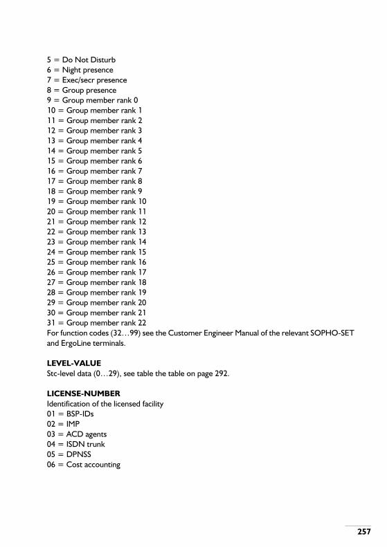
257
5 = Do Not Disturb6 = Night presence7 = Exec/secr presence8 = Group presence9 = Group member rank 010 = Group member rank 111 = Group member rank 212 = Group member rank 313 = Group member rank 414 = Group member rank 515 = Group member rank 616 = Group member rank 717 = Group member rank 818 = Group member rank 919 = Group member rank 1020 = Group member rank 1121 = Group member rank 1222 = Group member rank 1323 = Group member rank 1424 = Group member rank 1525 = Group member rank 1626 = Group member rank 1727 = Group member rank 1828 = Group member rank 1929 = Group member rank 2030 = Group member rank 2131 = Group member rank 22For function codes (32…99) see the Customer Engineer Manual of the relevant SOPHO-SET and ErgoLine terminals.
LEVEL-VALUEStc-level data (0…29), see table the table on page 292.
LICENSE-NUMBERIdentification of the licensed facility01 = BSP-IDs02 = IMP03 = ACD agents04 = ISDN trunk05 = DPNSS06 = Cost accounting

258
07 = System management08 = Full Detailed Call Recording09 = Least Cost Call Routing10 = Voice Mail Interface11 = iSNet Private Virtual Networking12 = Integrated Password Dialling13 = Music On Hold from IAS14 = Dynamic delay message15 = Operator monitoring16 = Service license17 = iSLinks for CSTA18 = Active CSTA monitors19 = Desksharing20 = Central Name Number Directory (CNND)21 = Ethernet CSTA23 = CSTA IO services24 = CSTA IO registration25 = Free Numbering
LINELine number displayed on the operators console (1…4 decimals)
LINES-PER-PAGENumber of lines per page (10…60)
LINE-POSIndicates if a line position must be assigned to a group member (0=no, 1=yes)
LINK-TYPEType of link to be assigned or displayed:1 = SM-CM2 = SM-PM controllable3 = SM-PM not controllable4 = SM-RPM controllable5 = SM-RPM not controllable6 = SM-IU controllable7 = SM-IU not controllable8 = SM-IM controllable10 = PMC-PMC11 = CSN-PMC

259
LOCAL-OPERATOR-MARKIndicates whether first assistance by local operator(s) must be tried before assistance according to assistance point will be attempted (0=no, do not try local operator first, 1=yes, try local operator first)
LOG-FILEFile specification consisting of:[LDN:]FILE-NAME[.EXTENSION[.GENERATION]]If GENERATION is omitted, the latest generation is used.If EXTENSION is omitted, LOG is used.If FILE-NAME is omitted, the name of the COMMAND-FILE is used.If LDN is omitted, the LDN of the COMMAND-FILE is used.

260
M
M-INDDisplayed value, indicating the number of calls in the M-queue.
M/SMain/Sub identification (0=main, 1=sub); identifies whether the protocol behaviour for a specified route will be main or sub.
MANAGER-INDEXIndex number of the requested manager type.
MANAGER-TYPEType of manager (0 = unit boundary, 1 = option, 2 = timer)
MARKHooter presence mark (0 = not present, 1 = present)
MAXMaximum paging length (MIN…20).
MAX-LENGTHMaximum number length (1…20). Must be ≥ MIN-LENGTH
MAXIMUM-VERSIONVersion that is supported by the equipment-type.
MD-TYPEType indication of the offered set of mode digits (0 = prefix mode, 1 = suffix mode)
MEMBER-BSP-IDBSP-ID of group member (see BSP-ID)
MEMBER-RANKRank of the member within a group.
MENUMenu number (0…59); as from SSW 805.24: (0…254).
MET-TYPE

261
Metering type:0 = Metering count of DNRs or BSP-IDs1 = Metering count of night extensions2 = Metering count of routes
MFC-ADD-INDEXAdditional requested MFC index, indicating:Priority of the received signal II, on MFC-TYPE =3;Previously sent signal II, on MFC-TYPE =5;No meaning on other MFC-TYPES.
MFC-INDEXThe requested MFC index (0…20). See table the table on page 261.
MFC-TYPESelected MFC structure (0…5). See table the table on page 261.Table B-2 Relation between MFC-TYPE and MFC-INDEX.
The call progress numbers have the following meaning:0 = Request next digit1 = Call successful2 = Extension busy3 = Time out4 = DDO successful5 = Not exist. number6 = DDI barred7 = Call not allowed8 = Congestion9 = Number unobtainable10 = Don't disturb11 = Auto. answer dialled12 = Auto. answer reply13 = Busy - call type 114 = Busy - call type 2
MFC-TYPE MFC-INDEX
0 Forward group I Forward signal (0…15)1 Forward group II Forward signal (0…15)2 Backward group A Call progress index (0…12 & 19…20)3 Backward group B Call progress index (1…10 & 13…18)4 Termination group A Backward signal index (0…15)5 Termination group B Backward signal index (0…15)

262
15 = Busy - call type 316 = Busy - call type 417 = Busy - call type 518 = Busy - call type 619 = Request first digit of CLI20 = Request next digit of CLI
MINMinimum paging length (1…6)
MIN-LENGTHMinimum number length (1…20)
MINIMUM-VERSIONVersion that is supported by the equipment-type.
MINUTESMinutes (0…59)
MISCELLANEOUSA string consisting of 12 characters: ABCDEFGHIJKLIn the case of X.21, only options B (=0), D (=0/1), E (=0/1), F (=7) and G (=2) are used, set all other options to 0.A: Echo during keyboard dialling? (0 = no, 1 = yes)B: Transmit unknown subscriber address? (0 = no, 1 = yes)In the case of DTE's: 0=subaddressing, 1=no subaddressing.C: Convert to upper case? (0 = no, 1 = yes)DHot line? (0 = no, 1 = yes)In the case of X.21: 0=switched, 1=leased.E: Byte oriented protocol? (0 = no, 1 = yes)F: Wordlength (5, 6, 7 or 8 bits)G: Parity (0 = no parity, 1 = even parity, 2 = odd parity)H: Stopbits (0 = 1 stop bit, 1 = 1.5 stop bit, 2 = 2 stop bits)I: Break sequence initiates call clear (0 = disable or 1 = enable)J: Rate adaption options (0=no options, 1= flow control end-to-end for asynchronous, or network independent clock for synchronous)K: Terminal adaption function (0 = X.30 TA, 1 = V.110 TA)L: Rate adaption method (0 = DRA, 1 = V.110 / X.30 / ECMA-102)
MnInternal call type

263
0 = individual1 = normal2 = preferred
MOD-DATE/TIMEModification date and time of a file.
MODEDisplay mode (0 = Abstract (default), 1 = Full display).
MODULEThis parameter indicates a PM module (0…31).
MONITOR-INTERVALThe time between measurements in minutes (1…100)
MONTHMonth (1…12)
MSN-TYPEType of Multi Subscriber Number:0 = No MSN1 = MSN2 = Fixed MSN digit

264
N
NAMEName string belonging to a DNR (1...20 characters). Enter the last name first.
NAME/SINCommand name or in the case of a MIS file the SnapshotIdentification Number (SIN): LOCAL or Nxxxxx (xxxxx = ident digits).
NARDProtection level in the format New, Append, Read, Delete (4 digits of 0…7).
NBR-OF-ITEMSThe number of items in a tone function (0…255).
NE-LEVELNight extension level:0 = INE1 = SCNE2 = MCNE3 = CANS
NE-UNITUnit in which the night extension is present (1…14).
NEAR-DESTNear destination unit, unit directly connected to own unit (1…14).
NETWORK-SINNetwork Snapshot Identification Number, 6 characters (Nxxxxx), first character is “N”.
NEW-PACKSee parameter PACK.
NIGHT-TRFCNight traffic class, see TRFC.
NLDisplayed parameter, indicating the number length.

265
NO-MSN-DIGITSNumber of MSN digits (0…6).
NUMBERInternal number (DNR) or external number (1... 20 digits) or code (1…6 digits).
NUMBER-LENGTHLength of internal number or code (1…6).In command ASINTN the following exceptions to this rule exist:
- In combination with result-ID 43 maximum 12 digits.- In combination with result-ID 82 the maximum length of this parameter is 20 digits - length
of given NUMBER.- In combination with result-ID 104…110, 113…115 this parameter indicates the length of
the password: 6…12 digits.- In combination with result-ID 111 and 112 this parameter indicates the length of the
password: 1…16 digits.- In combination with result-ID 118, 119 maximum 2 digits.- In combination with result-ID 133, this represents the PVN-MODE:
0 = PVN Standard Mode (default),1 = PVN Modem Mode,2 = PVN Compressed Mode.
- In combination with result-ID 135, 136 maximum 1 digit.- In combination with result-IDs 50/51, 20 digits (length of the password).
NVCTNumber of virtual circuits (0…30).

266
O
OBJ-INDEXA specific object in a PM-OBJECT, see table the table on page 266.Table B-3 Relation between PM-OBJECT and OBJ-INDEX.
OBJECTObject for Traffic Observation or Measurement.The DITRAF, DISPTO, ASTMOB and DETMOB commands ask for additional parameters, depending on the object.The relation between objects and parameters is given in table the table on page 266.Table B-4 Relation between OBJECT and Additional Parameters.
PM-OBJECT OBJ-INDEX
0 Signalling group data SIG-GROUP; see Chapter D.for a subset of the signalling data or the Signalling Data Manual for the complete set.
1 Slave data 6 ATC data8 Stc-tone data, see table C.9a.9 Stc-level data, see table C.9b.
2 PSC tone data Tone-function (0…99)For Tone-function, refer to Table C.9c. and for Tone-Source to Table C.10a.
3 Ring data Tone-function (100…199)For Tone-function, refer to Table C.9c., for Tone-Source of the PSC to Table C.10a for Tone-Source of the PMC to Table C.10b.
4 Ticker data Tone-function (200…204)For Tone-function, refer to Table C.9c., for Tone-Source of the PSC to Table C.10a for Tone-Source of the PMC to Table C.10b.
5 PMC tone data Tone-function (0…99)For Tone-function, refer to Table C.9c. and for Tone-Source to Table C.10b.
6 Direct downloadable signalling group data to PPU
Signalling group 9700 or 9800
OBJECT ADDITIONAL PARAMETERS
0 Bundles BUNDLE, UNIT [, FIGURE-TYPE]1 Routes ROUTE, FIGURE-TYPE2 Inter unit bundles IU-BUNDLE, UNIT, FIGURE-TYPE3 Inter unit routes IU-ROUTE, UNIT, FIGURE-TYPE4 Extensions UNIT, FIGURE-TYPE5 Groups GROUP-DNR, FIGURE-TYPE6 Paging routes PAG-ROUTE, FIGURE-TYPE7 Add on circuits UNIT, FIGURE-TYPE8 RKT-SDT circuits UNIT, FIGURE-TYPE9 SKT-RDT circuits UNIT, FIGURE-TYPE10 Incoming MFC circuits UNIT, FIGURE-TYPE
* = Only applicable for DISPTO, ASTMOB and DETMOB.

267
OFF-ONUsed in various commands. On or off (0 = off, 1 = on)
OFF-TIMETime on which the facility is downgraded in the format:days (1…7), hours (0…23) and minutes (0…55): DHHMM.The minutes are a multiple of five.
OLD-PACKSee parameter PACK.
ON-TIMETime in the format: DHHMM.In the case of facility timing: time of upgrading. In the case of traffic measurement: time on which measurement has to start.
OP-STATDisplayed value, indicating the status of the operator, i.e. Idle, Busy or OM mode.
OPERATOR-DNROperator directory number (see DNR)
OPERATOR-TYPEType of operator:0 = Basic operator console1 = Enhanced operator console2 = Digital operator console
OPTIONS
11 Outgoing MFC circuits UNIT, FIGURE-TYPE12 Socotel circuits UNIT, FIGURE-TYPE13 Convertors CONVERTOR-TYPE, UNIT, FIGURE-TYPE14 Specific operators OPERATOR-DNR, FIGURE-TYPE15 Queues ASSIST-GROUP, UNIT, FIGURE-TYPE16 Switching Network Channels SHELF,17, CRT (PM-Module), FIGURE-TYPE17 Call data UNIT, FIGURE-TYPE
* 18 Interunit traffic dispersion data SOURCE UNIT, UNIT, FIGURE-TYPE* 19 Dialled facilities data RESULT-ID, AG, UNIT, FIGURE-TYPE
21 Hatches UNIT, FIGURE-TYPE
OBJECT ADDITIONAL PARAMETERS
* = Only applicable for DISPTO, ASTMOB and DETMOB.

268
Bundle options MNOP[[QRSTUVWXYZ[A]] (0 = no, 1 = yes). When the bundle direction is incoming, QRSTUVWXYZA must be omitted.M = Long line checkN = Exchange line barred checkO = Register recall availableP = Echo canceller connectedQ = Metering available on bundleR = Detection first dialtone appliedS = Pre dialtone detection first dialtoneT = Pre dialtone detection second dialtoneU = Provisional switch throughV = Answer sensitiveW = DDO wait for answerX = Routing toneY = TRANSCOM tone detection and alarmingZ = DDO sent MFC area numberA = DDO local ring tone provided (since SSW 805.30)
ORDER-INDThis parameter specifies the place where the BSP must be inserted:0 = the BSP is inserted after any existing BSP with the same BSPT value;1 = the BSP is inserted before any existing BSP with the same BSPT value.
ORIG-BSP-IDOriginator directory number (see BSP-ID)
ORIG-CC-STRINGOriginal CLI or COL string which has to be translated : max. 16 digits, the string may end in wildcards (%).
ORIG-NUMBERNumber to be converted (1…6 digits)
ORIG-UNITOriginator unit (1…14)
OUT-OPTSOutgoing route options PQRST (each 0 = no, 1 = yes)P = Direct switch throughQ = Break in protection on outgoing callsR = D button allowed

269
S = Transit allowedT = Source identification
OUTPUT-FILEThe specification of the load control output file:(LDN:FILE-NAME.EXTENSION.GENERATION)
OUTPUT-FORMAT-VERSION0 = the default version that was supported by previous packages not having the possibility to define output formats.1 = supports a 16 digit Costcentre/PID field.2 = supports a 32 digit destination field.
OUTPUT-SWITCHSwitch to indicate if output of Traffic Measurement data has to be stopped or continued (0=stop, 1=continue).
OVERLAY-IDOverlay identity (6 chars).OM (sub)commands are 6 characters, SAS actions are 4 characters (preceded by l “As”).
OWNERPossible owners of resources are:NO = No ownerCP = Call processingSYS = SystemSAS = System AssurancePOM = Project engineering and Operational MaintenanceSTART = Owner of resource during HOTSTART

270
P
PACK
PAG-ROUTEPaging route number (0…254). See also ROUTE.
PAGING-CODEVirtual paging code (1…6 digits).
PARK-POSDefines if park positions must be assigned (0 = no, 1 = yes).If the value is 1, then 9 park positions are defined for the group DNR.If the park position is related to a group member, then 2 park positions are defined.
The FEPROM/RAM file names are Fcpppv.vll or Fccppv.vll, in which :'F' : all FEPROM/RAM file names start with an 'F'.'c' or 'cc' : indicates the type of board:
0x = CPU-ME/MT note1x = PMC-HR/MC 22 = DTX-I32 = DLC-U33 = DLX-U34 = DLX-L43 = DCC51 = DTU-VC52 = ALC-G7x = CPS (Z8K) note82 = PM Observer 9x = CCS noteA0 = SNS A1 = CIE note
'ppp' or 'pp' : indicates the package-identity. 'v.v' : indicates the version.'ll' : indicates the level update. Note : Package downloading is not under CPU control. Package-ids are only displayed
with OM command DIEXID (CCS) or DIPACK (CIE). Examples :F22010.105 : DTX-I package 201.01.05FA0000.304 : SNS package 000.03.04F98052.641 : CCS package 805.26.A (41 is the hex value for 'A')

271
PAT-MODEPeriodic Autonomous Test Mode (0=normal, 1=installation mode/factory test).
PCT-TYPECircuit type:1 = Line circuit (LCT)2 = Trunk circuit (TRC)3 = Operator circuit (OCT)4 = Convertor5 = RKT-SDT6 = SKT-RDT7 = In-MFC8 = Out-MFC9 = Paging circuit10 = RS-Socotel11 = Music on Hold12 = Music on COB13 = D channel14 = Trunk circuit ISDN15 = Wake_up/MW announcement circuit16 = Hatch17 = IAS-TSPCT types are discussed in more detail in Appendix C.
PERIODICITYThe item number where the periodicity sets in (0…254).This parameter must be smaller than the NR-OF-ITEMS.
PERIODSNumber of measurement periods of 15 minutes (1…254)
PID/COST-CENTREPersonal IDentification code (1…16 digits) or Cost Centre number (1…12 digits).
PM-OBJECTThe type of object when changing the PM projecting data, see table the table on page 266.
PORT-IDPort identifier (6 hexadecimal digits or *)
POST-DIAL

272
Post dialling mark (0 = no, 1 = yes)
PR#Displayed parameter, indicating the paging route number.
PRE-DIGITDigit, preceeding the external number (0…D).
PREF-CODEPreferred/Non prefered code (0=non-preferred, 1=preferred)
PRESDisplayed value, indicating the number of operators present.
PRES-CHDisplayed value, indicating the number of operators present and call handling.
PRES-POMDisplayed value, indicating the number of operators present and in the OM mode.
PRIO-CODE(Over)write Priority code1 = User can reprogram the key3 = User cannot reprogram the key
PROPProperties of a device: 6 bits (0=no, 1=yes), indicating respectively: Read access, write access, multiple file device, multiple file access device, variable record size, relative access device.
PROT-TYPEProtection type (0 =new, 1=append, 2=read, 3=delete)
PROTECTIONProtection level (0…7) of New, Append, Read or Delete
PROTOCOL-TYPEType of protocol used in device communication0 = Character protocol (CPU-ME/MT)1 = BCS protocol (CPU-ME/MT)2 = Logical protocol (CPS/CCS)

273
PSIProtocol Stack Identifier.
PTN-IDPVN Private Telecommunication Network Identity (0…9999).The default value is 9999.
PVN-MODEPVN working mode0 = PVN standard working mode (default)1 = PVN Network Signalling Convertor (NSC) mode2 = Compressed PVN Mode.
PW-GROUPPassword group (0…7). See table the table on page 273.
PW-KEYPassword key (0…15). See also table the table on page 273.Table B-5 Relation between PW-GROUP and PW-KEY.
PW-NBR-LENGTHOne or two digits in the range of 0...16 indicating the number of password digits to be given. If the parameter is omitted, it is assumed that no password digits have to be given.
PW-GROUP PW-KEY REMARKS
0 0…13 Authority class No1…4 0…7 1-New, 2 = Append, 3 = Read, 4 = Delete PW-KEY indicates the
protection level5 0…2 PW-KEY indicates the degradation level6 0 or 1 1 = INIDSK and CHACIV, 0 =not used.7 0...7 FTP access

274
Q
Q-POS-ALGORITHMQueue Position Algorithm1 = absolute position in the COB queue (default).2 = weighed position. The weighed position is calculated relative to the number of active agents, and the maximum length of the queue.
Q-PRIORITYQueue Priority (1…8)The Queue Priority number ranges from 1 (highest priority) to 8 (lowest, default).
QUEUE-TYPEType of operator queue (0…22):0 = Total values for M, C and A queues1 = A1 queue2 = A2 queue3 = A3 queue4 = A4 queue5 = A5 queue6 = A6 queue7 = A7 queue8 = A8 queue9 = A9 queue10 = A10 queue11 = A11 queue12 = A12 queue13 = A13 queue14 = A14 queue15 = A15 queue16 = A16 queue17 = M normal queue18 = M preferred queue19 = C DDI not answered queue20 = C DDI unsuccessful queue21 = C DDI recall not on hook queue22 = C DDI recall on hook queue

275
R
REAL-TYPEPaging type in the case of real paging0 = Meet-me paging urgent1 = Meet-me paging non-urgent2 = Speech paging urgent3 = Speech paging non-urgent4 = Display paging urgent5 = Display paging non-urgent
REFNAMEReference command name of the file.
REMOTE-USER-GROUPRemote user group (0…1)
REP-FACTORNumber of test repeats (0…9) (0 means continuous testing)
REPORT-FORM0 = brief report1 = verbose2 = exchange type
REPORT-TYPEThe following report types exist:00 = No suspicion report01 = No successors failed02 = Cancelled event of interest03 = Suspicion level exceeded04 = Expired alarm integration05 = Expired isolation integr.06 = Solved alarm07 = Passive alarm08 = Suspicion09 = Alarm integration10 = Successors failed11 = Blocked alarm12 = Manually controlled test

276
13 = Silent alarm14 = Minor alarm15 = Major alarm99 = Project engineering alarm
RES-IDMiscellaneous resource type0 = Add on circuit1 = RKT-SDT2 = SKT-RDT3 = Incoming MFC4 = Outgoing MFC
RESOURCE-TYPEResource type. See table the table on page 276.Table B-6 Resource Type List.
RESOURCE-TYPE DESCRIPTION
000 Line circuit (LCT)001 Trunk circuit (TRC)002 Operator circuit (OPC)003 Inter-unit line circuit004 Receiver-Sender Socotel005 Add-on Circuit006 Converter007 Receiver keytone - sender dial tone008 Sender keytone - receiver dial tone009 Incoming MFC010 Outgoing MFC011 Hatch012 Peripheral Module (PM)013 Board014 Device015 Communication Interface boards, except the CII (type 027)016 Null tone017 External ring tone018 Internal ring tone019 Music On Hold tone (MOH)020 Switching Network Link (SNL)021 Switch and Control Unit (SCU)022 Central Module (CM)023 Central Memory Slice (CMS)024 Majority Interface Circuit (MIC)025 Clock Signal Generator (CSG)026 Clock Reference Unit (CRU)

277
REST-MODERestoration mode (0…2)0 = First party control1 = Calling party control2 = Called party control
RESTARTA variable indicating the type of start to be executed:0 = Warmstart stand-by cluster1 = Coldstart stand-by cluster2 = Re-project stand-by cluster3 = Reload stand-by cluster
RESTRICTIONRestriction (0 = unrestricted or 1 = restricted)
027 Communication Interface Internal (CII)028 Switching Network Module (SM)029 Logical Channel030 Physical Channel031 Testbus032 Paging circuit033 Camp on Busy tone034 Busy tone035 CRU entry036 Unit Logical Link (ULL)037 Digital Trunk Unit-Control038 Virtual Channel039 D-Channel040 Shelf041 Multi function board042 SN routing tone043 SN announcement044 IAS module (IM)045 IAS board046 IAS timeslot047 Peripheral Module (PM)048 Prim - pm - network / pm - network049 SN specific announcement050 Communication Interface External (CIE)051 Switch and Sense Unit (SSU)052 Backup and Interface Module (BIM)255 Null resource
RESOURCE-TYPE DESCRIPTION

278
RESULT-IDResult identity (3 digits). See tables the table on page 278 and the table on page 282.Table B-7 Result IDs.
RES-ID
DESCRIPTION FROM DIAL TYPE / SOURCE
0 1 2 3 4 5 6 7 8 9DDI
DDO
DPNSS
IN
DPNSS O
UT
00* Second external dialtone place
-- -- -- -- -- -- -- -- -- -- -- X -- --
01 No direct result X X X X X X X -- X X X X X X10** Internal number X X X -- X @ X -- X X X -- X X11 Operator M code dialled
generalX X -- -- X -- -- -- X X X -- X --
12 Meet-me paging urgent with CLI 1)
X X X -- X -- -- -- X X X -- X X
13 Meet-me paging non urgent with CLI 1)
X X X -- X -- -- -- X X X -- X X
14 Priority trunk access code X X X -- X -- -- -- X X X -- X X20 Paging answer prefix X -- -- -- -- -- -- -- X X -- -- X --21 Trunk access code X X X -- X -- -- -- X X X -- X X22* External number -- -- -- -- -- -- -- -- -- -- -- X -- --23** Common pool abbr. dialling X X X -- -- -- -- -- X X -- -- X --24** Group pool abbr. dialling X X X -- -- -- -- -- X X -- -- -- --25 Access individual abbr.
number@ @ @ -- -- -- -- -- @ @ -- -- -- --
26 Access last external number @ @ @ -- -- -- -- -- @ @ -- -- -- --27 Activate FM from primary @ @ -- -- -- -- -- -- @ @ -- -- -- --28 Prepare FM from primary @ @ -- -- -- -- -- -- @ @ -- -- -- --29 Activate FM from destination X X -- -- -- -- -- -- X X -- -- -- --30 Cancel FM from destination
sel.X X -- -- -- -- -- -- X X -- -- -- --
31 Cancel FM from destination coll.
X X -- -- -- -- -- -- X X -- -- -- --
32 Cancel FM from primary X X -- -- -- -- -- -- X X -- -- -- --33 Pick up general X X -- -- -- -- -- -- X X -- -- -- --34 Pick up individual X X -- -- -- -- -- -- X X -- -- -- --35 Switch out of group by
member@ @ -- -- -- -- -- -- @ @ -- -- -- --
x Normally accessable from this dial source * Automatically assigned with ASEXTN
1)New names (as from SSW 805.25). See the next table for the old names. 2)
These Result-IDs are valid as from SSW 805.25.
-- Not accessable from this dialtype or source ** Assigned with ASBLCK
*** assigned with CHCSDD
@ Normally accessable, but appropriate facility class mark or OM facility configuration must be assigned to the origating party

279
36 Switch in group by member @ @ -- -- -- -- -- -- @ @ -- -- -- --37 Switch out of group by
supervisor@ @ -- -- -- -- -- -- @ @ -- -- -- --
38 Switch in group by supervisor @ @ -- -- -- -- -- -- @ @ -- -- -- --39 Executive secretary access @ @ -- -- -- -- -- -- @ @ -- -- -- --40 Executive secretary absent @ @ -- -- -- -- -- -- @ @ -- -- -- --41 Executive secretary present @ @ -- -- -- -- -- -- @ @ -- -- -- --42 Executive secretary
complete-- -- -- -- -- -- -- X -- -- -- -- -- --
43 Cost centre prefix X X X -- -- -- -- -- X X -- -- -- --44 Night extension absent @ @ -- -- -- -- -- -- @ @ -- -- -- --45 Night extension present @ @ -- -- -- -- -- -- @ @ -- -- -- --46 Cans code dialled X -- -- -- -- -- -- -- X X -- -- -- --47 Operator M code dialled
priorityX X -- -- X -- -- -- X X X -- X --
48 Operator A general -- -- -- -- -- -- -- -- -- -- X -- X --49 Operator A queue -- -- -- -- -- -- -- -- -- -- X -- X --50 Desksharing active @ -- -- -- -- -- -- -- -- -- -- -- -- --51 Desksharing deactive @ -- -- -- -- -- -- -- -- -- -- -- -- --52 Test telephone @ -- -- -- -- -- -- -- @ @ -- -- -- --53 Emergency access code X -- -- -- -- -- -- -- X X -- -- -- --54 Dial up data protection @ @ -- -- -- -- -- -- @ @ -- -- -- --55 Add on prefix -- @ -- -- -- -- -- -- -- -- -- -- -- --56 Automatic ring back -- -- -- @ -- -- -- -- -- -- -- -- -- --57 Cancel automatic ring back X X -- -- -- -- -- -- X X -- -- -- --58 Break in -- -- -- @ -- -- -- -- -- -- -- -- -- --59 Bypass code -- -- -- @ -- -- -- -- -- -- -- -- -- --60 Malicious call trace -- @ X -- -- -- -- -- -- -- -- -- -- --61 Extension programming -- -- -- -- -- -- -- -- -- -- -- -- -- --62 Common floor service
dialledX X -- -- -- -- -- -- X X -- -- -- --
63 Laundry dialled X X -- -- -- -- -- -- X X -- -- -- --64 Information dialled X X -- -- -- -- -- -- X X -- -- -- --65 Reception dialled X X -- -- -- -- -- -- X X -- -- -- --
RES-ID
DESCRIPTION FROM DIAL TYPE / SOURCE
0 1 2 3 4 5 6 7 8 9DDI
DDO
DPNSS
IN
DPNSS O
UT
x Normally accessable from this dial source * Automatically assigned with ASEXTN
1)New names (as from SSW 805.25). See the next table for the old names. 2)
These Result-IDs are valid as from SSW 805.25.
-- Not accessable from this dialtype or source ** Assigned with ASBLCK
*** assigned with CHCSDD
@ Normally accessable, but appropriate facility class mark or OM facility configuration must be assigned to the origating party

280
66 Set don't disturb @ @ -- -- -- -- -- -- @ @ -- -- -- --67 Reset don't disturb @ @ -- -- -- -- -- -- @ @ -- -- -- --68 Convertor prefix X X -- -- -- -- -- -- X X X -- -- --69 Store individual abbr. number @ @ -- -- -- -- -- -- @ @ -- -- -- --70 Erase individual abbr. number @ @ -- -- -- -- -- -- @ @ -- -- -- --71 Replace ind. abbr. number @ @ -- -- -- -- -- -- @ @ -- -- -- --72 Upgrade traffic service class @ -- -- -- -- -- -- -- @ @ -- -- -- --73 Downgrade traffic service
class@ -- -- -- -- -- -- -- @ @ -- -- -- --
74 No traffic service class selected
@ -- -- -- -- -- -- -- @ @ -- -- -- --
75 Call waiting code dialled X X -- -- -- -- -- -- X X -- -- -- --76 Message waiting LED on type
0X X -- -- -- -- -- -- X X -- -- -- --
77 Message waiting LED on type 1
X X -- -- -- -- -- -- X X -- -- -- --
78 Message waiting LED on type 2
X X -- -- -- -- -- -- X X -- -- -- --
79 Message waiting LED off type 0
X X -- -- -- -- -- -- X X -- -- -- --
80 Message waiting LED off type 1
X X -- -- -- -- -- -- X X -- -- -- --
81 Message waiting LED off type 2
X X -- -- -- -- -- -- X X -- -- -- --
82 TMS dialled X -- -- -- -- -- -- -- X X -- -- X --83 Activate FM from primary
group@ @ -- -- -- -- -- -- @ @ -- -- -- --
84 Prepare FM from primary group
@ @ -- -- -- -- -- -- @ @ -- -- -- --
85 Cancel FM from primary group
@ @ -- -- -- -- -- -- @ @ -- -- -- --
86 Activate FM from dest. group X X -- -- -- -- -- -- X X -- -- -- --87 Cancel FM from dest. sel.
groupX X -- -- -- -- -- -- X X -- -- -- --
RES-ID
DESCRIPTION FROM DIAL TYPE / SOURCE
0 1 2 3 4 5 6 7 8 9DDI
DDO
DPNSS
IN
DPNSS O
UT
x Normally accessable from this dial source * Automatically assigned with ASEXTN
1)New names (as from SSW 805.25). See the next table for the old names. 2)
These Result-IDs are valid as from SSW 805.25.
-- Not accessable from this dialtype or source ** Assigned with ASBLCK
*** assigned with CHCSDD
@ Normally accessable, but appropriate facility class mark or OM facility configuration must be assigned to the origating party

281
88 Cancel FM from dest. coll. group
X X -- -- -- -- -- -- X X -- -- -- --
89 Auto answering circuit dialled -- -- -- -- -- -- -- -- -- -- X -- -- --90 COB display for supervisor @ -- -- -- -- -- -- -- @ @ -- -- -- --91 Network access code X X X -- X X -- -- X X X -- X --92 CSDN access code @ -- -- -- -- -- -- -- @ @ -- -- -- --93 Give a line -- -- X -- -- -- -- -- -- -- -- -- -- --94 Start post dialling -- X -- -- -- -- -- -- -- -- -- -- -- --95 Enquiry on trunk initiation -- X X -- -- -- -- -- -- -- -- -- -- --96 Enquiry on trunk take over -- X X -- -- -- -- -- -- -- -- -- -- --98 Activate diversion on busy X X -- -- -- -- -- -- X X -- -- -- --99 Cancel diversion on busy X X -- -- -- -- -- -- X X -- -- -- --
100 Activate fixed follow me X X -- -- -- -- -- -- X X -- -- -- --101 Start call waiting -- -- -- @ -- -- -- -- -- -- -- -- -- --102 Start camp on busy (COB) -- -- -- @ -- -- -- -- -- -- -- -- -- --103 General cancel code X X -- -- -- -- -- -- X X -- -- -- --104 Change password X X -- -- -- -- -- -- X X -- -- -- --105 Enable up/downgrading X X -- -- -- -- -- -- X X -- -- -- --106 Disable up/downgrading X X -- -- -- -- -- -- X X -- -- -- --107 Upgrade traffic class X X -- -- -- -- -- -- X X -- -- -- --108 Downgrade traffic class X X -- -- -- -- -- -- X X -- -- -- --109 Password DDO from own X X -- -- -- -- -- -- X X -- -- -- --110 Password DDO from other X X X -- -- -- -- -- X X -- -- -- --111 Cost centre modulo X X X -- -- -- -- -- X X -- -- -- --112 Cost centre validate X X X -- -- -- -- -- X X -- -- -- --113 Access port direct (SSM) X X X -- -- -- -- -- X X X -- X --114 Access port call back (SSM) X X X -- -- -- -- -- X X X -- X --115 Cancel call back call (SSM) X X X -- -- -- -- -- X X X -- X --116 Private call X X X -- -- -- -- -- X X -- -- -- --117 Directed call X X -- -- -- -- -- -- X X -- -- -- --118 Short code dialling group X X -- -- -- -- -- -- X X -- -- -- --119 Pick up by rank number X X -- -- -- -- -- -- X X -- -- -- --120 Speech paging urgent with
CLI 1)X X X -- X -- -- -- X X X -- X X
RES-ID
DESCRIPTION FROM DIAL TYPE / SOURCE
0 1 2 3 4 5 6 7 8 9DDI
DDO
DPNSS
IN
DPNSS O
UT
x Normally accessable from this dial source * Automatically assigned with ASEXTN
1)New names (as from SSW 805.25). See the next table for the old names. 2)
These Result-IDs are valid as from SSW 805.25.
-- Not accessable from this dialtype or source ** Assigned with ASBLCK
*** assigned with CHCSDD
@ Normally accessable, but appropriate facility class mark or OM facility configuration must be assigned to the origating party

282
Table B-8 Result-ID descriptions valid prior to SSW 805.25
121 Speech paging non urgent with CLI 1)
X X X -- X -- -- -- X X X -- X X
122 Display paging urgent with CLI 1)
X X X -- X -- -- -- X X X -- X X
123 Display paging non urgent with CLI 1)
X X X -- X -- -- -- X X X -- X X
124 Display paging urgent 1) X X X -- X -- -- -- X X X -- X X125 Display paging non urgent 1) X X X -- X -- -- -- X X X -- X X126 Recording of announcement @ -- -- -- -- -- -- -- @ @ -- -- -- --127 CallManager MIS dialled @ @ -- -- -- -- -- -- @ @ -- -- -- --128 ACD group day prefix @ @ -- -- -- -- -- -- @ @ -- -- -- --129 ACD group night prefix @ @ -- -- -- -- -- -- @ @ -- -- -- --130 Dial up break in @ @ -- -- -- -- -- -- @ @ -- -- -- --131 Dial up CLIR X X -- -- -- -- -- -- X X -- -- -- --132 PVN user channel address -- -- -- -- -- -- -- -- -- -- X -- -- --133 PVN signalling channel
address-- -- -- -- -- -- -- -- -- -- X -- X --
134 Overlay X X -- -- -- -- -- -- -- -- -- -- -- --135 Log on prefix X X -- -- -- -- -- -- -- -- -- -- -- --136 Log off prefix X X -- -- -- -- -- -- -- -- -- -- -- --137 CSTA control prefix X -- -- -- -- -- -- -- -- -- -- -- -- --138 Subnetwork access code X X X -- X X -- -- X X X -- X --139 Meet me paging urgent 2) X X X -- X -- -- -- X X X -- X X140 Meet me paging non urgent
2)X X X -- X -- -- -- X X X -- X X
141 Speech paging urgent 2) X X X -- X -- -- -- X X X -- X X145*** CSTA server dialled (since
SSW 805.30) X X X -- X -- -- -- X X X -- X X
RESULT ID Description
12 Meet me paging urgent prefix13 Meet me paging non urgent
RES-ID
DESCRIPTION FROM DIAL TYPE / SOURCE
0 1 2 3 4 5 6 7 8 9DDI
DDO
DPNSS
IN
DPNSS O
UT
x Normally accessable from this dial source * Automatically assigned with ASEXTN
1)New names (as from SSW 805.25). See the next table for the old names. 2)
These Result-IDs are valid as from SSW 805.25.
-- Not accessable from this dialtype or source ** Assigned with ASBLCK
*** assigned with CHCSDD
@ Normally accessable, but appropriate facility class mark or OM facility configuration must be assigned to the origating party

283
RETRIEVE-ACTIONIndicates which data should be retrieved(0 = all data, 1 = network data)
RINRoute Identification Number (1…4 digits).
ROUTERoute number (0…254)
ROUTE-ALTERNRouting alternative0 = primary1 = alternative
ROUTE-TABLERoute table number (0…254).
ROUTE-TYPERoute for alarm signalling:0 = Suppress all1 = MDF2 = Standard (according to PE file)3 = Isolate unit (No outgoing alarms to other units)4 = Standard operator and MDF
120 Speech paging urgent121 Speech paging non urgent 122 Display paging urgent ANT (= Aut. Number Transmission)123 Display paging non urgent ANT (= Aut. Number Transmission)124 Display paging urgent no ANT (= Aut. Number Transmission)125 Display paging non urgent no ANT (= Aut. Number Transmission)
RESULT ID Description

284
S
SCTIndex, indicating the software state (4 decimal numbers)
SECR-BSP-IDSecretary BSP-ID (see BSP-ID)
SECR-RANKSecretary rank in pool (0…9)
SELECT-ANNOUNCEMENT-DATA0 = Announcement data for assistance group1 = Announcement data for ACD group2 = Announcement data for music on hold
SEQSequence number of a bundle in a route or a line in a bundle.Sequence numbers are assigned automatically and represent the order in which the lines or bundles are defined. It also represents the order in which the bundle or line is selected.
SEQUENCE-NOSequence number of a link (0…7)
SEQUENCE-TABLESequence table, indicates which route table should be selected (1…5). 1 indicates the default table, 2…5 can be used for Least Cost Routing and iSNet Private Virtual Networking (select with facility timing).
SERVER-AND-ACTION-CODEA digit string with the format: P[Q]QP is the server code. It indicates the type of server addressed:0 = Message server1 = ACD MIS server[Q]Q is the action requested from the server. The range depends on the type of server given by SERVER-CODE. The following actions are defined for each application type:
Message Server 0 = normal text message to server 1 = urgent text message to server 2 = forward normal text message 3 = forward urgent text message

285
SET-NAMEFilename of a set (6 characters)
SET-TYPEType of set:0 = all types1 = active resident sets2 = inactive resident sets3 = overlay sets4 = resident sets
SHELFShelf identity, UUCCSUU= Unit (1…14), must be omitted for single unit systemsCC= Cabinet (01…15)S = Shelf (1…4)
SHELF-TYPEIndicates the type of shelf:0 = PM-2500 shelf1 = SM-2500 shelf2 = CM-2500 shelf3 = CM-SM-1025 shelf4 = CM-SM-1025 redesign shelf5 = CM-SM-2500 redesign shelf6 = PM-1100 shelf7 = RPM-1100 shelf8 = RPM-255U shelf
4 = broadcast normal text message 5 = broadcast urgent text messageACD MIS Server 0 = agent login 1 = agent logout 2 = agent not ready 3 = agent ready 4 = agent not ready by supervisor 5 = agent ready by supervisor 6 = agent logout by supervisor 7 = agent login and present 8 = enter transaction code 9 = agent request consultation 10 = ACD group to day 11 = ACD group to night

286
9 = RPM-255L shelf10 = PM-255 upper11 = PM-255 lower12 = PM-55 upper13 = PM-55 lower14 = PM-250/100015 = CSM
SIGCH-ADDRESSSignalling channel address of the opposite ISPBX (1…20 digits)
SIGCH-TUSignalling channel timer unit (0=seconds, 1=minutes); identifies the unit of the time value specified by parameter SIGCH-TV.
SIGCH-TVSignalling channel timer value (0…16383).
SIG-IDSignal identifier (0000…FFF (hex) or * = don't care)
SIG-GROUPSignalling group AAAA.AAAA : PPU signalling group. See appendix C.
SMART-BOX-EMMercury smart box emulation (0 = no, 1 = yes).
SND-DTSecond external dial tone option (0 = no, 1 = yes)
SOFT-RINGControls the soft ring that can be activated for function keys where a group member is monitored. (0…3).0 = no softring1 = one softring beep2 = two softring beeps3 = three softring beeps
SOURCE-FILESpecification of the source file in the format:

287
LDN:FILENAME.EXTENSION[.GENERATION]
SPEED+MODEConcatenation of Terminal speed and Conversation mode: TTCThe following terminal speeds are possible (in Bauds):1 = 502 = 753 = 1104 = 1505 = 2006 = 3007 = 6008 = 12009 = 127510 = 240011 = 360012 = 480013 = 720014 = 960015 = 1200016 = 1440017 = 1920018 = 3840019 = 4800020 = 5600021 = 64000The following conversation modes are possible:0 = Full duplex, asynchronous1 = Full duplex, synchronous2 = Half duplex, asynchronous3 = Half duplex, synchronous4 = Simplex outgoing, asynchronous5 = Simplex outgoing, synchronous6 = Simplex incoming, asynchronous7 = Simplex incoming, synchronous
START-FLGFlag indicating if the STWARM command is generated (0 = no, 1 = yes).
SUBSCR-CATCategory of subscriber indicating the type of calling party (1…15)

288
SUPERVISOR-DNRSupervisor BSP-ID (see BSP-ID)
SWITCH-ALLOWANCEMember can switch absent in group (0 = no, 1 = yes)

289
T
TERMINALTerminal name of 5 characters (eg. VDUxx)
TERMINAL-TYPETerminal type0 = VDU1 = Operator console2 = Operator console with key3 = TMS (SystemManager)
THRESHOLD-PRIORITYAcd group priority (0=No priority, 1=Priority group).
TICSThreshold of metering ticks (max 4 digits)
TICKER-SOURCEAdded ticker function source (0…2).0 = no ticker2 = ticker tone 03 = ticker tone 1
TIMETime specification <HOURS>:<MINUTES>
T-VALUENumber of time units (0…63).
TONE-AND-DDI-OPTSTone and direct dialling in options PQ[RSTUVWX]:P = Busy tone before answer (0=no, 1=yes)Q = Busy tone after answer (0=no, 1=yes)R = DDI tone to be sent to external party (0…4)
0 = no tone1 = internal dial tone2 = external dial tone3 = internal ring tone4 = external ring tone

290
S = Traffic class (0…7)T = Action when DDI to busy extension (0…9)U = Action when DDI dial time out (0…9)V = Action when DDI ringing time out (0…9)W = Action when DDI to unallocated number (0…9)X = Action when unsuccessful DDI call (0…9)For TUVWX the following actions are possible:0 = Busy tone1 = NU tone2 = Clear backward3 = No action4 = COB and send answer5 = Operator or busy tone6 = Operator or nu tone7 = Operator or clear back8 = Operator or no action9 = Operator or night extension
TONE-FUNCTIONDefault settings of Tone, Ring and Ticker functions can be found in the Signalling Data manual. In this manual there are more Tone, Ring and Ticker functions as given in this tableThe ones not mentioned here have become obsolete or are intended for future use.
FUNCTION FUNCTION ID DESCRIPTION
000 Internal ring tone.001 External ring tone.002 Internal dial tone.003 First external dial tone.004 Second external dial tone.005 Delayed hotline dial tone.006 Busy tone.007 Number unobtainable tone.008 Congestion tone.009 Diversion active dial tone.
Tone Function 010 Confirmation tone.011 Urging tone.012 Call waiting tone burst.013 Paging absent tone.014 Paging in progress tone.015 Bypass tone.017 Camp on busy tone to caller.018 Park tone.019 Through connect ring tone.

291
Table B-9 Description of Tone, Ring and Ticker Functions.
TONE-SRCTone source number on the PSC-A tone PROM or PSC-G Country Group 1 (see table the table on page 292) or on the PMC (see table the table on page 293). See table the table on page 294 for the relation between tone sources on the PSC and PMC.Table B-10 Stc-Tone Data for PMC.
020 Ticker tone 0.021 Ticker tone 1.024 ARB destination ring back tone.025 Alternative routing warning tone.026 Enter password tone.027 Routing tone.
Ring Function 100 Internal ring current.101 External ring current.102 Automatic ring back current.103 Emergency alarm ring current.104 Through connect ring current.105 Service A ring (used for wake-up ring).106 Service B ring (used for message waiting ring).107 Ring burst.
Ticker Function 200 Break-in ticker.201 Add-on ticker.202 Urging ticker203 Call waiting ticker.204 Dial up Break in Ticker.
FREQ- VALUE TONE TYPE FREQUENCY LEVELS (dBm0) REMARKS
0 Silence1 DTMF 697 1209 - 4.2 - 22 DTMF 697 1336 - 4.2 - 23 DTMF 697 1477 - 4.2 - 24 DTMF 697 1633 - 4.2 - 25 DTMF 770 1209 - 4.2 - 26 DTMF 770 1336 - 4.2 - 27 DTMF 770 1477 - 4.2 - 28 DTMF 770 1633 - 4.2 - 29 DTMF 852 1209 - 4.2 - 2
10 DTMF 852 1336 - 4.2 - 211 DTMF 852 1477 - 4.2 - 212 DTMF 852 1633 - 4.2 - 213 DTMF 941 1209 - 4.2 - 214 DTMF 941 1336 - 4.2 - 215 DTMF 941 1477 - 4.2 - 2
FUNCTION FUNCTION ID DESCRIPTION

292
Table B-11 Coded Tone Levels for PMC.
Note: The default settings of Tone, Ring and Ticker functions can be found in the Signalling Data Manual.The Signalling Data Manual shows more Tone, Ring and Ticker functions as given in this table. The ones not mentioned have become obsolete or are intended for future use.Table B-12 PSC Tone Source Numbers.
16 DTMF 941 1633 - 4.2 - 217 Ticker 400 0 4 cycles18 Ticker 425 0 4 cycles19 Single 400 020 Single 425 021 Single 440 022 Single 450 023 Single 620 024 Single 950 025 Single 1400 026 Single 1800 027 Dual 150 450 0 - 928 Dual 350 440 - 3 - 329 Dual 440 480 - 3 - 330 Dual 480 620 - 3 - 331 Multiply 33.33 400 032 Multiply 25 425 033 Carrier 33.33 400 - 2 80% modulation34 H'FF 0 Idle pattern for
DTX-I35 H'00 0 Zero pattern
INDEX LEVEL (dB) INDEX LEVEL (dB) INDEX LEVEL (dB)
0 0 10 - 10 20 - 201 - 1 11 - 11 21 - 212 - 2 12 - 12 22 - 223 - 3 13 - 13 23 - 234 - 4 14 - 14 24 - 245 - 5 15 - 15 25 - 256 - 6 16 - 16 26 - 267 - 7 17 - 17 27 - 278 - 8 18 - 18 28 - 289 - 9 19 - 19 29 - 29
TONE-SOURCE
FREQUENCY (Hz) LEVEL (dBm0) COMMENT
00 - - - - - - Contents PROM identification01 - - - - - - Idle pattern (silence)
FREQ- VALUE TONE TYPE FREQUENCY LEVELS (dBm0) REMARKS

293
Table B-13 PMC Tone Source numbers.
02 4 periods of 400 0 Ticker (incl. 500 msec)03 4 periods of 425 - 12 Ticker (incl. 500 msec)04 4 periods of 425 - 3 Ticker (incl. 500 msec)05 150 + 440 - 6 - 15 06 400 - 3 07 400 - 608 400 - 909 400 - 1210 400 x 33.3 - 3 11 400 x 33.3 - 9 400 Hz modulated by 33.3 Hz12 400 x 33.3 - 17 13 425 - 3 14 425 - 615 425 - 916 425 - 1217 425 - 2318 425 x 25 - 10 425 Hz modulated by 25 Hz19 425 x 25 - 14 20 450 0 21 450 - 422 450 - 823 950 - 4.5 24 950 - 925 950 - 1326 1400 - 4.5 27 1400 - 928 1400 - 1329 1800 - 4.5 30 1800 - 931 1800 - 13
TONE SOURCE
TONE SPECIFICATION SLAVE DATA REMARK
FREQ. (Hz) LEVEL (dBm) TONE LEVEL
0 425 - 3 18 3 ticker1 0 0 0 0 silence2 425 - 12 20 12 H'FF*3 450 - 8 22 84 950 - 13 24 135 150 440 - 6 - 15 17 6 6 1400 - 13 25 137 1800 - 13 26 13
* Tone source 2 has a fixed setting.
TONE-SOURCE
FREQUENCY (Hz) LEVEL (dBm0) COMMENT

294
Table B-14 Conversion Tone Source Numbers of PSC-A to PMC.
TREEAnalysis tree number (0…254)
8 400 - 9 19 99 400 - 12 19 12
10 425 - 23 20 2311 425 x 25 - 10 32 1012 400 x 33.3 - 17 31 1713 425 - 3 30 314 450 0 22 015 425 - 9 20 916 941 1336 - 10.2 - 8 14 6 DTMF `0'17 697 1209 - 10.2 - 8 1 6 DTMF `1'18 697 1336 - 10.2 - 8 2 6 DTMF `2'19 697 1477 - 10.2 - 8 3 6 DTMF `3'20 770 1209 - 10.2 - 8 5 6 DTMF `4'21 770 1336 - 10.2 - 8 6 6 DTMF `5'22 770 1477 - 10.2 - 8 7 6 DTMF `6'23 852 1209 - 10.2 - 8 9 6 DTMF `7'24 852 1336 - 10.2 - 8 10 6 DTMF `8'25 852 1477 - 10.2 - 8 11 6 DTMF `9'26 941 1209 - 10.2 - 8 13 6 DTMF `*'27 941 1477 - 10.2 - 8 15 6 DTMF `#'28 697 1633 - 10.2 - 8 4 6 DTMF `A'29 770 1633 - 10.2 - 8 8 6 DTMF `B'30 852 1633 - 10.2 - 8 12 6 DTMF `C'31 941 1633 - 10.2 - 8 16 6 DTMF `D'
PSC-A TONE SOURCE PMC TONE SOURCE
4 016 217 1018 1120 1422 325 426 628 631 7
TONE SOURCE
TONE SPECIFICATION SLAVE DATA REMARK
FREQ. (Hz) LEVEL (dBm) TONE LEVEL
* Tone source 2 has a fixed setting.
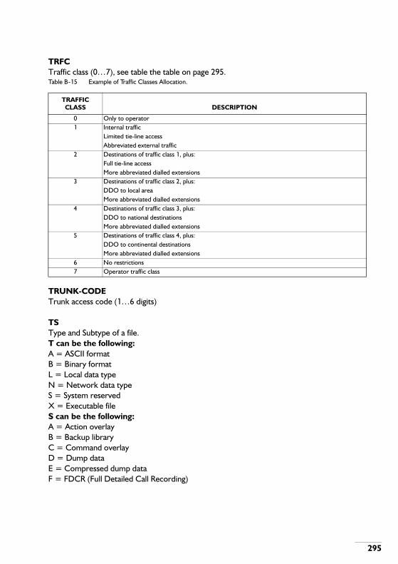
295
TRFCTraffic class (0…7), see table the table on page 295.Table B-15 Example of Traffic Classes Allocation.
TRUNK-CODETrunk access code (1…6 digits)
TSType and Subtype of a file.T can be the following:A = ASCII formatB = Binary formatL = Local data typeN = Network data typeS = System reservedX = Executable fileS can be the following:A = Action overlayB = Backup libraryC = Command overlayD = Dump dataE = Compressed dump dataF = FDCR (Full Detailed Call Recording)
TRAFFIC CLASS DESCRIPTION
0 Only to operator1 Internal traffic
Limited tie-line accessAbbreviated external traffic
2 Destinations of traffic class 1, plus:Full tie-line accessMore abbreviated dialled extensions
3 Destinations of traffic class 2, plus:DDO to local areaMore abbreviated dialled extensions
4 Destinations of traffic class 3, plus:DDO to national destinationsMore abbreviated dialled extensions
5 Destinations of traffic class 4, plus:DDO to continental destinationsMore abbreviated dialled extensions
6 No restrictions7 Operator traffic class

296
G = General dataI = PE initial fileJ = JournalK = Metering dataL = Backup locationM = Memory imageN = Compressed memory imageO = Traffic observationP = Program libraryQ = Sequence numberR = Resident setS = Snapshot subcommandsT = Toll ticketingU = Unit configuration
TYPE-CODEType code PQRSTU (for each letter: 0 = no, 1 = yes)P = Call forwarding on busy executive to secretaryQ = Secretary allowed to switch absentR = Single executive poolS = Single secretary poolT = Busy indication in the case of executive and secretary busyU = Executive line position pickup by related executives allowed

297
U
UADisplayed value, indicating the number of unanswered calls.
UCAUser Channel Address (1…6 digits)
UCA-PREFIXUser Channel Address prefix (1…20 digits)
UnUnit number (n=1 to 14)
UNITUnit number (1…14)As from SSW 805.28 unit '0' may be given. This is the unit the OM terminal is connected to.
UNIT+BUNDLEComposite parameter of unit and bundle; format [UU]BBB
UNIT+DESTLocal destination id [UU]DDD
UNIT-INDICATORIndicates if a single unit or multi unit call should be observed:0 = single unit call1 = multi unit call
UNIT-TTime unit (0…4):0 = 10 msec1 = 100 msec2 = 1 sec3 = 10 sec4 = continuous
UNS-BIDSDisplayed value, indicating the total number of unsuccessful bids on a group or group members.

298
UP-TRFCUpgraded traffic class, see parameter TRFC.
USER-MODE0 = normal PVN (default)1 = delayed PVN
USRCH-TUUser channel timer unit; identifies the unit of the time value specified by parameter USRCH-TV.0 = seconds1 = minutes
USRCH-TVUser channel timer value (0…16383)
USER-TYPEIndicates for which type of user a routing table is valid:0 = Normal extension1 = Operator2 = Priority extension

299
V
V.24-CIRCUITSV option (0…14) or digit string ABCDEFGHIJ KL, each 0 or 1, to set the circuits individually, see table the table on page 299.Table B-16 V-OPTION.
If the circuits are filled in individually (0 = off, 1 = on):
VOICE/DATAVoice data indication (V or D)
VOLUMEVolume name of the medium you wish to format (1…6 characters)
V-OPTION 0 1 2 3 4 5 6 7 8 9 10 11 12 13 14
CT108-2 1 0 0 0 0 1 1 1 1 1 1 1 1 1 1CT108-ON 0 0 0 0 0 0 0 1 1 0 0 1 1 1 1CT105-CREQ 0 0 0 0 0 0 0 0 0 0 0 0 0 1 0CT103-DCALL 0 0 0 0 0 0 0 0 0 1 0 0 0 0 1CT107-AUTON 1 0 0 1 1 0 0 0 0 1 1 1 1 0 0AUTOM-ANSW 0 0 0 0 0 0 0 0 0 0 0 0 0 0 0CT105-109 0 0 0 0 0 0 0 0 0 0 0 0 0 0 0CT106-109-INH 0 0 0 0 0 0 0 0 0 0 0 0 0 0 0CT105-ON 0 0 1 0 1 0 1 0 1 0 1 0 1 0 1DGUARD-ACT 0 0 0 0 0 0 0 0 0 0 0 0 0 0 0DGUARD-INC 0 0 0 0 0 0 0 0 0 0 0 0 0 0 0V.25BIS 0 0 0 0 0 0 0 0 0 0 0 0 0 0 0
A CT108-2: CT108 not as call request. CT108 set as 108.1 or 108.2. If this circuit is on it is used as CT108.2 else it is used as C108.1 (call request).
B CT108-ON: If this option is chosen, CT108 is assumed permanently on, independent of the actual state of the circuit.
C CT105-CREQ: This option allows CT105 to be used as a call request.D CT103-DCALL: Activity on CT103 initiates a call request.E CT107-AUTON: CT107 as call clear indication. CT107 may be turned off independent
of the state of CT108.F AUTOM-ANW: Automatic answer on incoming call.G CT105-CT109: CT105 connected to CT109.H CT106-CT109-INH: CT109 enables CT106.I CT105-ON: CT105 is assumed continuously on, independent of the actual state of
the circuit.J DGUARD-ACT: No activity on CT103 or CT104 during certain time clears the call.K DGUARD-INC: No data activity on incoming call within certain time clears the call.L V.25BIS: V-interface working according to V.25bis.In the case of X.21: A= Autoclear, F=Auto answer.

300
W
WADisplayed value, indicating the number of waiting calls.
WAITWait for completion of the delete operation.Yes = 1No = 0
WEEKDay of the week (1…7)
WINDOWTMS/SOPHO SystemManager service number (1…9, 81…89); see note 1Normally the following values are used, check this in the TMS/SOPHO SystemManager documentation.From the iS3000 to TMS/SOPHO SystemManager:81 = External Service Display82 = Room Status83 = Automatic entry of messages84 = Night Watchman control85 = Peripheral facility manager request86 = Peripheral facility manager user-to-PFM87 = Access managerFrom TMS/SOPHO SystemManager to the iS3000:02 = Wake up03 = Message waiting without announcement04 = Automatic Directory Dialling05 = Bar/Unbar extension (see note 2)06 = Message waiting with announcement / security patrol manager alarm07 = Peripheral facility manager-to-user08 = Port protection call backNote 1: The window numbers in the OM command are in hexadecimal. Window numbers in the subcommands are in decimal. E.g.: hexadecimal window number 81 corresponds to window number 129 in decimal.Note 2: In SSW 805.29 switching service number 5 is extended an therefor renamed to 'Change PBX data'.Service number 5 can now be used for bar/unbar an extension and to set/reset a PBX feature, e.g. activate/deactivate don't disturb.

301
WINDOW-SIZEThe number of simultaneous processes sent to the TMS/SOPHO SystemManager (0…254)
WRITE-SELDetermines the type of data stored in a system dump:0 = Write current environment only1 = Write all data

302
Y
YEARYear (1985…2050)

303
C . BOARD AND PCT TYPES
C.1. BOARD-TYPE TABLE
The table below lists all the boards. The board-type is not mentioned if it can not be projected by ASBRDS (like PSU, LTU etc.) The signalling group, mentioned in this table, corresponds to the application. Other applications with corresponding signalling groups can be found in the Signalling Data Manual. The PCT-TYPE used by the application is in the “PCT-TYPES ON BOARD” column. The mode of operation for individual circuits can be changed to a PCT-TYPE, which is mentioned between square brackets, by first DEPCTB and subsequently ASPCTB.PCT-TYPES are discussed in section "PCT-TYPE TABLE" on page 309.Table C-1 Various Types of Boards
CIRCUIT NAMEBOARD
TYPESign
Group
HARDW.
TYPEPCT-TYPES ON
BOARD APPLICATIONS
ACC 08 3205 35 LCT [TRC/MOH/Ann] ExtensionACU (APNSS) APNSS-boardALC-Axx 03 3204 35 LCT [MOH/Ann] extensionALC-Bxx 03 3204 35 LCT [MOH/Ann] extensionALC-Exx 06 3205 35 LCT [MOH/Ann] extensionALC-Fxx/G 06 3204 35 LCT [MOH/Ann] extension/clearing
signalALC-Fxx/G 06 3210 35 LCT [MOH/Ann] extension/message-
waiting led.AOC on PMC 0A04 255 [OCT]AS01 on ACC01 3304 35 [TRC] ALS70AS0B on ACC0B 3304 35 [TRC] ALS70ASU-G 06 9B17 255 Standard board 16
linesASU-G 06 3Exx 255 [TRC] Subscr. SignallingASU-G 06 3Exx 255 [TRC] PD SignallingATU-AS01 22 3304 35 TRC ALS70ATU-AS01 22 3704 35 TRC Eind-OverdragerATU-AS0B 22 3304 35 TRC ALS70ATU-AS11 22 3704 35 TRC Eind-OverdragerATU-AS36 22 3F04 35 TRC Austria enhanced SSATU-AS48 22 4904 35 TRC FRENCH DDOATU-CH01 22 3404 255 TRC cailhoATU-CH02 22 3804 35 TRC German cailhoATU-DI13 24 4104 255 TRC United Kingdom DDIATU-EL03 24 4204 35 TRC EC and loop disconn.ATU-EM 35 5F04 255 TRC external alarmATU-EM-D 22 3604 35 TRC Dig. data +EM

304
ATU-EMXX 22 See "PCT-TYPE TABLE" on page
309
35*) TRC 1 bit protocol See "PCT-TYPE TABLE" on page 309.
ATU-EMXX 22 7704 35*) TRC Italy EMATU-EMXX 22 7604 35*) TRC Spain EMATU-G 24 3304 35 TRC ALS70ATU-G 24 3704 35 TRC Eind-OverdragerATU-G 24 3E04 35 TRC SSATU-G2 24 4604 35 TRC PDO SwedenATU-G2 24 3E0C 35 TRC SS SwedenATU-G2 24 7804 35 TRC PD2 New ZealandATU-G3 1) 24 3E1A 35 TRC PD1 SpainATU-G3 1) 24 3E16 35 TRC SS GermanyATU-G3 1) 24 3E04 35 TRC SS ChinaATU-G3 1) 24 3E04 35 TRC SS South AfricaATU-G3 1) 24 4706 35 TRC SS FranceATU-G3 2) 24 3E04 35 TRC SS0ATU-G3 2) 24 3E0C 35 TRC PD1ATU-G3 2) 24 3304 35 TRC ALS70ATU-G3 2) 24 3704 35 TRC AS0/AS2 Eind-
OverdragerATU-G3 2) 24 3E1A 35 TRC PD1C SpainATU-G3 2) 24 4706 35 TRC SS08 FranceATU-G4 24 3E04 35 TRC SS01/AS2D ItalyATU-G4 24 3704 35 TRC AS21/AS2D ItalyATU-G5 24 3E04 35 TRC SS0M BrazilATU-G5 24 3E0C 35 TRC PD1M BrazilATU-G5 24 3704 35 TRC AS0M BrazilATU-G6 24 3E1F 35 TRC SS02 GermanyATU-IL31 22 4A04 255 TRC ChinaATU-ILxx 22 See Table
D.2.35*) TRC 1 bit protocol See
Table D.2.ATU-LB01 22 3A04 255 TRC Local batteryATU-LB12 22 See Table
D.2.35*) TRC 1 bit protocol See
Table D.2.ATU-LD28 22 4804 35 TRC French DDIATU-LDxx 22 3B04 35 TRC LOOPDICONN (SS-
DC5)ATU-PA 30 3D04 255 PAGING CIRCUIT PagingATU-PD05 22 450B 35 TRC Denmark polarity det.ATU-PD07 22 4604 35 TRC Sweden polarity detATU-PD11 22 3E04 35 TRC polarity detectionATU-PDx8 24 4704 35 TRC French polarity det.
CIRCUIT NAMEBOARD
TYPESign
Group
HARDW.
TYPEPCT-TYPES ON
BOARD APPLICATIONS
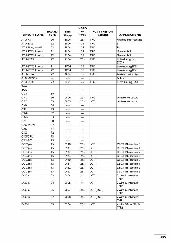
305
ATU-PSI 20 3E04 255 TRC Analoge door-contactATU-SS02 22 3E04 35 TRC SSATU-SSxx, not 02 23 3E04 35 TRC SSATU-ST02 2 ports 21 3904 35 TRC German IKZATU-ST02 4 ports 22 3904 35 TRC German IKZATU-ST03 22 4304 255 TRC United Kingdom
DC10ATU-ST12 2 ports 21 3C04 35 TRC Luxembourg IKZATU-ST12 4 ports 22 3C04 35 TRC Luxembourg IKZATU-ST26 22 4004 35 TRC Austria 3 wire Sign.ATX (APNSS) -- ---- --- APNSSATU-EC03 22 3504 35 TRC Earth-Calling (EC)BAC -- ---- ---BCC -- ---- ---CCS 88 ---- ---CFC 24 0E04 255 TRC conference circuitCFC 03 0E05 255 LCT conference circuitCI-X 84 ---- ---CIE 89 ---- ---CII-A 82 ---- ---CII-B 83 ---- ---CPS 80 ---- ---CPU-ME/MT 87 ---- ---CRU 71 ---- ---CSG 72 ---- ---CSG/CRU 73 ---- ---CSN-BC 75 ---- ---DCC (4) 15 0920 255 LCT DECT, BB-section 0DCC (4) 15 0921 255 LCT DECT, BB-section 1DCC (4) 15 0922 255 LCT DECT, BB-section 2DCC (4) 15 0923 255 LCT DECT, BB-section 3DCC (8) 13 0920 255 LCT DECT, BB-section 0DCC (8) 13 0921 255 LCT DECT, BB-section 1DCC (8) 13 0922 255 LCT DECT, BB-section 2DCC (8) 13 0923 255 LCT DECT, BB-section 3DLC-A 02 2804 4*) LCT 2 wire U-interface
TMPDLC-B 04 2806 4*) LCT 2 wire U-interface
TMPDLC-C 05 2807 255 LCT [OCT] 2 wire U-interface
TMPDLC-D 07 2808 255 LCT [OCT] 2 wire U-interface
TMPDLC-I 05 0904 255 LCT 4 wire S0-bus TMP/
1TR6
CIRCUIT NAMEBOARD
TYPESign
Group
HARDW.
TYPEPCT-TYPES ON
BOARD APPLICATIONS

306
DLC-U (15) 10 0912 255 LCT [OCT] TMP/1TR6+take-over/ETSI
DLC-U (15) 10 090A 255 LCT [OCT] 2w, TMP/1TR6/ETSIDLC-U (7) 12 090F 255 LCT [OCT] 2w, TMP/1TR6/ETSIDLX-L (15) (15 ports)
64 0930 255 LCT 2w (2B1Q), TMP/1TR6,ETSI
DLX-L (15) (30 ports)
65 090A 255 LCT 2w (2B1Q), TMP/1TR6,ETSI
DLX-U (15) 15 ports
67 0930 255 LCT 2w (Upn), TMP/1TR6
DLX-U (15) 30 ports
68 090A 255 LCT 2w (Upn), TMP/1TR6
DLX-U (31) 31 ports
69 0931 255 LCT 2w (Upn), TMP/1TR6
DOC on PMC -- 1904 255 [OCT]DTA 00 3204 35 LCT digital test accessDTU-BA 26 6605 255 TRC 2B+D DPNSS, B sideDTU-BA 26 6604 255 TRC 2B+D DPNSS, A sideDTU-BA 28 5C04 255 ISDN-TRC 2B+D 1TR6DTU-CC 50 2004 48 (R)PM2500 onlyDTU-PH 18 5D04 255 ISDN-TRC 30B+D 1TR6DTU-PH 18 5D0D 255 ISDN-TRC 30B+D ETSI
International free numb.
DTU-PH 19 6705 255 TRC/D-CHANNEL 30B+D DPNSS, B side
DTU-PH 19 6704 255 TRC/D-CHANNEL 30B+D DPNSS, A side
DTU-PH 19 6708 255 TRC/D-CHANNEL 30B+D DASSDTU-PU as DTU-CA
25 3004 49*) TRC Belgium
DTU-PU as DTU-CA
25 See Table D.2.
49*) TRC 1 bit protocol See Table D.2.
DTU-PU as DTU-CA
25 2B04 49*) TRC Italy
DTU-PU as DTU-CA
25 2D04 49*) TRC France
DTU-PU as DTU-CA
25 2C04 49*) TRC Sweden
DTU-PU as DTU-CA
25 2E04 49*) TRC South Africa
DTU-PU as DTU-CA
25 2904 49*) TRC Netherlands (ALS70)
DTU-PU as DTU-CA
25 3104 49*) TRC Denmark
DTU-PU as DTU-CA
25 5004 49*) TRC Thailand
CIRCUIT NAMEBOARD
TYPESign
Group
HARDW.
TYPEPCT-TYPES ON
BOARD APPLICATIONS
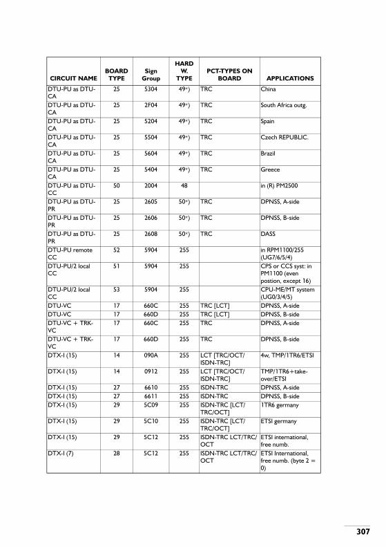
307
DTU-PU as DTU-CA
25 5304 49*) TRC China
DTU-PU as DTU-CA
25 2F04 49*) TRC South Africa outg.
DTU-PU as DTU-CA
25 5204 49*) TRC Spain
DTU-PU as DTU-CA
25 5504 49*) TRC Czech REPUBLIC.
DTU-PU as DTU-CA
25 5604 49*) TRC Brazil
DTU-PU as DTU-CA
25 5404 49*) TRC Greece
DTU-PU as DTU-CC
50 2004 48 in (R) PM2500
DTU-PU as DTU-PR
25 2605 50*) TRC DPNSS, A-side
DTU-PU as DTU-PR
25 2606 50*) TRC DPNSS, B-side
DTU-PU as DTU-PR
25 2608 50*) TRC DASS
DTU-PU remote CC
52 5904 255 in RPM1100/255 (UG7/6/5/4)
DTU-PU/2 local CC
51 5904 255 CPS or CCS syst: in PM1100 (even postion, except 16)
DTU-PU/2 local CC
53 5904 255 CPU-ME/MT system (UG0/3/4/5)
DTU-VC 17 660C 255 TRC [LCT] DPNSS, A-sideDTU-VC 17 660D 255 TRC [LCT] DPNSS, B-sideDTU-VC + TRK-VC
17 660C 255 TRC DPNSS, A-side
DTU-VC + TRK-VC
17 660D 255 TRC DPNSS, B-side
DTX-I (15) 14 090A 255 LCT [TRC/OCT/ISDN-TRC]
4w, TMP/1TR6/ETSI
DTX-I (15) 14 0912 255 LCT [TRC/OCT/ISDN-TRC]
TMP/1TR6+take-over/ETSI
DTX-I (15) 27 6610 255 ISDN-TRC DPNSS, A-sideDTX-I (15) 27 6611 255 ISDN-TRC DPNSS, B-sideDTX-I (15) 29 5C09 255 ISDN-TRC [LCT/
TRC/OCT]1TR6 germany
DTX-I (15) 29 5C10 255 ISDN-TRC [LCT/TRC/OCT]
ETSI germany
DTX-I (15) 29 5C12 255 ISDN-TRC LCT/TRC/OCT
ETSI international, free numb.
DTX-I (7) 28 5C12 255 ISDN-TRC LCT/TRC/OCT
ETSI International, free numb. (byte 2 = 0)
CIRCUIT NAMEBOARD
TYPESign
Group
HARDW.
TYPEPCT-TYPES ON
BOARD APPLICATIONS

308
DTX-I (7) 11 090F 255 LCT [TRC/OCT/ISDN-TRC]
S0-bus
DTX-I (7) 26 660C 255 TRC [LCT/OCT/ISDN-TRC]
DPNSS, A side
DTX-I (7) 26 660D 255 TRC [LCT/OCT/ISDN-TRC]
DPNSS, B side
DTX-I (7) 28 5C08 255 ISDN-TRC [LCT/TRC/OCT]
1TR6 germany
ESU (-LG) /MCE 34 1E04 64 Emergency switchingIAS as IAS-A 14p 05 2807 255 LCT/MOH/AnnIAS as IAS-A 30p 09 280D 255 LCT/MOH/AnnIAS iS3070/3090 55 ---- --- IAS 30+1 portsIAS+CPU+ME/MT 14p
57 5E04 255 IAS-TS [MOH] IAS 14 ports
IAS+CPU+ME/MT 30p
56 5E05 255 IAS-TS [MOH] IAS 30 ports
INC -- ---- ---IPH-A -- ---- ---IPH-B 31 2504 255 D-channel DPNSS/DASSKTLC 8/A 03 2304 35 LCT 4 wire analoge setKTLC-E 06 2305 35 LCT 4 wire analoge setLDC -- ---- ---LTU-(C/F) -- ---- ---MC -- ---- ---MCE see ESUMCI 85 ---- ---MIC 81 ---- ---MLU convertor 33 1604 255 convertor [TRC]MLU leased Line 22 1604 255 TRC [convertor]MOH-I -- ---- ---OIU 32 1706 255 OCT SupervisorPM-observer 36 6604 255PMC-HR 90 0B04 255 RKT-SDT/SKT-RDT
[OCT/HATCH]PMC-LU 93 0B04 255 RKT-SDT/SKT-RDT
[OCT/HATCH]PMC-MC 91 0B04 255 RKT-SDT/SKT-RDT
[OCT/HATCH]PMC-MC MASTER 92 0B04 255 RKT-SDT/SKT-RDT
[OCT/HATCH]PSC 94 ---- ---PSU-ML (D)/F/etc. -- ---- ---RST-IM 41 1504 82 IN-MFCRST-KDxx 40 1404 255 RKT-SDT/SKT-RDTRST-OM 43 150A 83 OUT-MFCRST-SL 42 1C04 81 RS-SOCOTEL Socotel France
CIRCUIT NAMEBOARD
TYPESign
Group
HARDW.
TYPEPCT-TYPES ON
BOARD APPLICATIONS

309
Table C-2 1-Bit Protocols
C.2. PCT-TYPE TABLE
C.2.1. Line Circuit (LCT)
RST-SL 42 2104 80 RS-SOCOTEL Socotel SpainSCU 70 ---- ---SNS 77 ---- ---SS01 on ACC01 -- 3E04 35 [TRC] Eind overdragerSS0B on ACC0B -- 3E04 35 [TRC] Eind overdragerVPU -- ---- ---1) 9562 158 810002) 9562 158 81100*
Note: These hardware test types only apply to the PM2500, use type 255 for other types of PM.
PPU MODULE_TYPESIGNALLING
GROUP REMARKS
ATU-EM 3604 EM GeneralATU-EM-AS 7304 France EM-ASATU-EM-LD 7404 France EM-LDATU-EM2-PULSE 7004 EM pulse protocolATU-EM3 6F04 Sweden IF3 and BrasilATU-EM4 6E04 Sweden IF4ATU-EM5 6D04 Sweden IF5ATU-EM6 6C04 Sweden IF6ATU-EM7 6B04 Sweden IF7ATU-EM8 6A04 Sweden IF8ATU-EMF 7204 FranceATU-EMG 7504 Germany
ACC/ALC-Axx/ALC-E/ALC-BxxSign. Group Remarks
3204 Enquiry by earth button, no auxiliary pulse detect (8 lines).3205 Enquiry by earth button, no auxiliary pulse detect (16 lines).3206 Enquiry by dial-one or auxiliary pulse.3207 Enquiry by dial-one or auxiliary pulse and Special timing for Spain3208 Enquiry by hook flash.320A Enquiry by dial-one or auxiliary pulse.
CIRCUIT NAMEBOARD
TYPESign
Group
HARDW.
TYPEPCT-TYPES ON
BOARD APPLICATIONS

310
320C Enquiry by dial-one.3216 Enquiry by aux. loop swedish signalling.3218 Enquiry by aux. loop or enquiry digit [0].321A Enquiry by aux. loop or enquiry digit [0] swedish signalling.
ALC-FSign. Group Remarks
3205 Enquiry by earth button, no auxiliary pulse detect.Polarity reverse used to indicate release.
3207 Enquiry by dial-one or auxiliary pulse and Special timing for SpainPolarity reverse used to indicate release.
3210 French signallingPolarity reverse used to indicate release.
3216 Enquiry by aux. loop Swedish Signalling.Polarity reverse used to indicate release.
321A Enquiry by aux. loop or enquiry digit [0] Swedish signalling.Polarity reverse used to indicate release.
ALC-GSign. Group Remarks
3205 Enquiry by earth button, no auxiliary pulse detect.Polarity reverse used to indicate release.
3207 Enquiry by dial-one or auxiliary pulse and Special timing for SpainPolarity reverse used to indicate release.
3216 Enquiry by aux. loop Swedish signalling.Polarity reverse used to indicate release.
321A Enquiry by aux. loop or enquiry digit [0] Swedish signalling.Polarity reverse used to indicate release.
CFCSign. Group Remarks
0E05 Conference circuit as line circuit
DCC (4 and 8)Sign. Group Remarks
0920 DECT, BB-section 00921 DECT, BB-section 10922 DECT, BB-section 20923 DECT, BB-section 3
DLC-A/B/C/DSign. Group TMP
2804 level: English

311
language: English280A level: Dutch
language: Dutch280C modem converter function
DLC-ISign. Group TMP 1TR6 Call
HandoverLayer 1
0904 level: NET33 extended passive bus or point to point
language: German 0905 level: NET33 short passive bus
language: German 0906 level: terminal
setting dependent
extended passive bus or point to point
language: terminal setting dependent
0907 level: terminal setting dependent
short passive bus
language: terminal setting dependent
090D level: Dutch extended passive bus or point to point
language: Dutch 090E level: Dutch short passive bus language: Dutch 0910 modem convertor function extended passive bus
or point to point
DLC-USign. Group TMP 1TR6 Call
HandoverETSI Aut.
MSN Insertion
DWNLD
0904 level: NET33 + language: German
090F level: terminal setting dependent
+ +
language: terminal setting dependent
090D level: Dutch + language: Dutch
0910 modem convertor function
+ +

312
0911 level: terminal setting dependent
+ + +
language: terminal setting dependent
0914 level: terminal setting dependent
+
language: terminal setting dependent
0915 level: terminal setting dependent
+
language: terminal setting dependent
0916 level: terminal setting dependent
+ +
language: terminal setting dependent
DLX-LSign. Group Remarks
090A DLX-L (15) in 2B mode0930 DLX-L (15) in 1B mode
0908… 090B + DLX-L (15) in 2B mode if the DLX-L is used to substitute the DLX-U, DLC-U or DTX-I.
0910 … 0917 Note: The DLX-L offers a different extension interface as the DLX-U, DLC-U and DTX-I. Therefore it cannot be used as a one-to-one replacement of the DLX-U, DLC-U and DTX-I.
DLX-USign. Group Remarks
090A DLX-U(15) in 2B mode0930 DLX-U(15) in 1B mode0931 DLX-U(31) in 1B mode
0908… 090B + DLX-U(15) in 2B mode if the DLX-U is used to substitute the DLC-U or DTX-I.
0910… 0917 Note: The DLX-U offers a different extension interface as the DLC-U and DTX-I. Therefore it cannot be used as a one-to-one replacement of the DLC-U and DTX-I.

313
DTASign. Group Remarks3204 DTA circuit
DTU-VC without TRK-VCSign. Group Remarks6614 passive side [automatic answer calls]6615 active side [generate Call-request]
DTX-ISign. Group TMP 1TR6 Call
Handover
ETSI Aut. MSN
Insertion
DWNLD Layer 1
0904 level: NET33 + extended passive bus or point to point
language:
German
0905 level: NET33 + short passive bus
language:
German
0906 level: terminal setting dependent
+ extended passive bus or point to point
language:
terminal setting dependent
0907 level: terminal setting dependent
+ short passive bus
language:
terminal setting dependent
0909 level: NET33 + remote extension
language:
German
090A level: terminal setting dependent
+ + extended passive bus or point to point
language:
terminal setting dependent

314
090B level: terminal setting dependent
+ + remote extension
language:
terminal setting dependent
090D level: Dutch + extended passive bus or point to point
language:
Dutch
090E level: Dutch + short passive bus
language:
Dutch
090F level: terminal setting dependent
+ + extended passive bus or point to point
language:
terminal setting dependent
0910 modem convertor function
+ + extended passive bus or point to point
0911 level: terminal setting dependent
+ + + remote extension
language:
terminal setting dependent
0912 level: terminal setting dependent
+ + + extended passive bus or point to point
language:
terminal setting dependent
0913 level: terminal setting dependent
+ + + short passive bus
language:
terminal setting dependent
0914 level: terminal setting dependent
+ extended passive bus or point to point
language:
terminal setting dependent

315
C.2.2. Trunk Circuit (TRC)
0915 level: terminal setting dependent
+ short passive bus
language:
terminal setting dependent
0916 level: terminal setting dependent
+ + extended passive bus or point to point
language:
terminal setting dependent
0917 level: terminal setting dependent
+ + short passive bus
language:
terminal setting dependent
ASU-GSign. Group Remarks
9B17 Sign. Group of the ASU-G board-16 lines.3Exx Subscriber signalling (Sign. Group per PCT)3Exx Polarity Detect signalling (Sign. Group per PCT)
TU-AS01 on ACC01 / TU-AS0B on ACC0BSign. Group Remarks
3304 ALS70
ATU-AS01 / ATU-AS0BSign. Group Remarks
3304 ALS703704 Eind-Overdrager
ATU-AS11Sign. Group Remarks
3704 Eind-overdrager
ATU-AS36Sign. Group Remarks
3F04 Austria enhanced SS

316
ATU-AS48Sign. Group Remarks
4904 French DDO
ATU-AS36Sign. Group Remarks
3F04 Austria enhanced SS
ATU-AS48Sign. Group Remarks
4904 French DDO
ATU-CH01Sign. Group Remarks
3404 Cailho
ATU-CH02Sign. Group Remarks
3804 German Cailho
ATU-DI13Sign. Group Remarks
4104 United Kingdom DDI
ATU-EC03Sign. Group Remarks
3504 Earth-Calling
ATU-EL03Sign. Group Remarks
4204 EC and loop disconnect
ATU-EMSign. Group Remarks
3604 EM general7304 France EM-AS7404 France EM-LD7004 EM pulse protocol6F04 Sweden IF3 and Brasil

317
6E04 Sweden IF46D04 Sweden IF56C04 Sweden IF66B04 Sweden IF76A04 Sweden IF87204 France 1bit7504 Germany 1bit7604 Spain EM7704 Italy EM
ATU-GSign. Group Remarks
3304 ALS703704 Eind-Overdrager3E04 SS0
ATU-G2Sign. Group Remarks
7804 New Zealand PD234604 Sweden PD03E0C Sweden SS0
ATU-G3 (9562 158 81000)Sign. Group Remarks
3E1A Spain PD13E16 Germany SS3E04 SS04706 France SS08
ATU-G3 (9562 158 81100)Sign. Group Remarks
3E04 SS03E0C PD13304 ALS703704 AS0/AS2 Eind-Overdrager4706 SS08 France3E1A PD1C Spain
ATU-G4Sign. Group Remarks
3E04 SS01/SS0D Italy3704 AS21/AS2D Italy

318
ATU-G5Sign. Group Remarks
3E04 SS0M Brazil3E0C SS01/SS0D Italy3704 AS21/AS2D Italy
ATU-G6Sign. Group Remarks
3E1F SS02 Germany
ATU-IL31Sign. Group Remarks
4A04 China IL
ATU-ILxxSign. Group Remarks
3604 EM general7304 France EM-AS7404 France EM-LD7004 EM pulse protocol6F04 Sweden IF3 and Brasil6E04 Sweden IF46D04 Sweden IF56C04 Sweden IF66B04 Sweden IF76A04 Sweden IF87204 France 1bit7504 Germany 1bit
ATU-LB01Sign. Group Remarks
3A04 Local Battery
ATU-LB12Sign. Group Remarks
3604 EM general7304 France EM-AS7404 France EM-LD7004 EM pulse protocol6F04 Sweden IF3 and Brasil6E04 Sweden IF46D04 Sweden IF5

319
6C04 Sweden IF66B04 Sweden IF76A04 Sweden IF87204 France 1bit7504 Germany 1bit
ATU-LD28Sign. Group Remarks
4804 French DDI
ATU-LDxxSign. Group Remarks
3B04 Loop disconnect (SS-DC5)
ATU-PDx8Sign. Group Remarks
4704 French polarity detection
ATU-PD05Sign. Group Remarks
450B Denmark polarity detection
ATU-PD07Sign. Group Remarks
4604 Sweden polarity detection
ATU-PD11Sign. Group Remarks
3E04 Polarity detection
ATU-PSI / ATU-SSxxSign. Group Remarks
3E04 SS
ATU-ST02 with 2 ports and/or 4 portsSign. Group Remarks
3904 German IKZ

320
ATU-ST03Sign. Group Remarks
4304 United Kingdom DC10
ATU-ST12 2 ports, 4 portsSign. Group Remarks
3C04 Luxembourg IKZ
ATU-ST26Sign. Group Remarks
4004 Austria 3 wire signalling
CFCSign. Group Remarks
0E04 Conference circuit as trunk circuit
DTU-PU as DTU-CASign. Group Remarks
3604 EM general7304 France EM-AS7404 France EM-LD7004 EM pulse protocol6F04 Sweden IF3 and Brasil6E04 Sweden IF46D04 Sweden IF56C04 Sweden IF66B04 Sweden IF76A04 Sweden IF87204 France 1bit7504 Germany 1bit2904 Channel associated (Netherlands (ALS70))2B04 Channel associated (Italy)2C04 Channel associated (Sweden)2D04 Channel associated (France)2E04 Channel associated (South Africa)2F04 Channel associated (South Africa outgoing)3004 Channel associated (Belgium)3104 Channel associated (Denmark)5004 Channel associated (Thailand)5204 Channel associated (Spain)5304 Channel associated (China)5404 Channel associated (Greece)

321
5504 Channel associated (Czech Republic)5604 Channel associated (Brazil)
DTU-PR (or DTU-PU used as DTU-PR)Sign. Group Remarks
2605 DPNSS, A side2606 DPNSS, B side2608 DASS
DTU-VC with TRK-VCSign. Group Remarks
660C DPNSS, A side660D DPNSS, B side
MLUSign. Group Remarks
160C Carrier detection selection: no actionSpeed selection: lowDirection selection: outgoing
160E Carrier detection selection: guarding of the lineSpeed selection: lowDirection selection: outgoing
1610 Carrier detection selection: no actionSpeed selection: highDirection selection: outgoing
1612 Carrier detection selection: guarding of the lineSpeed selection: highDirection selection: outgoing
1614 Carrier detection selection: no actionSpeed selection: lowDirection selection: incoming
1616 Carrier detection selection: guarding of the lineSpeed selection: lowDirection selection: incoming
1618 Carrier detection selection: no actionSpeed selection: highDirection selection: incoming
161A Carrier detection selection: guarding of the lineSpeed selection: highDirection selection: incoming
161C Carrier detection selection: call detectionSpeed selection: lowDirection selection: call dependent
161E Carrier detection selection: call detectionSpeed selection: high

322
C.2.3. Operator Circuit (OCT)
Table C-3 Various Types of Operator Circuits
Direction selection: call dependent1620 Carrier detection selection: call detection
Speed selection: lowDirection selection: outgoing
1622 Carrier detection selection: call detectionSpeed selection: highDirection selection: outgoing
1624 Carrier detection selection: call detectionSpeed selection: lowDirection selection: incoming
1626 Carrier detection selection: call detectionSpeed selection: highDirection selection: incoming
TU-SS on ACC01, TU-SS0B on ACC0BSign. Group Remarks
3E04 Eind overdrager
BOARD-NAME PPU MODULE_TYPESIGNALLING
GROUPHARDW.
TYPE
AOC on PMCwith SV20 AOC 0A04 255with SV25 AOC 0A04 255with SV50 AOC 0A05 255
DLC-C/Dwith PNT1-SV25 SuperVisor-30 1905 255with PNT1-SV35 SuperVisor-30 1905 255with SV30 SuperVisor-30 1904 255
DLC-U (15)/(7)with PNT1-SV25 SuperVisor-1TR6 6005 255with PNT1-SV35 SuperVisor-1TR6 6005 255with PNT1-SV55 SuperVisor-1TR6 6004 255with SV30 SuperVisor-30-D 5B04 255with PNT1-SSV60 SuperVisor-60 6404 255
DOC on PMCwith PNT1-SV25 SuperVisor-30 1905 255with PNT1-SV35 SuperVisor-30 1905 255with SV30 SuperVisor-30 1904 255
DTX-I (15) (7)with SV25 SuperVisor-1TR6 6005 255with SV35 SuperVisor-1TR6 6005 255with SV55 SuperVisor-1TR6 6004 255

323
C.2.4. Converter
C.2.5. RKT-SDT
C.2.6. RDT-SKT
with PNT-L/SSV60 SuperVisor-60 6404 255DTX-I (15) (7)
with SV20 OIU 1706 255with SV25 OIU 1706 255with SV50 OIU 1706 255
MLUSign. Group Remarks
1604 Speed selection: lowDirection selection: call dependent
1606 Speed selection: highDirection selection: call dependent
1608 Speed selection: call dependent (high speed is 1200 bits/s)Direction selection: call dependent
160A Speed selection: call dependent (high speed is 2400 bits/s)Direction selection: call dependent
PMCSign. Group Remarks
0B04 Receiver key tone, sender dial tone
RST-KDxxSign. Group Remarks
1404 Receiver key tone, sender dial tone
PMCSign. Group Remarks
0B04 Receiver dial tone, sender key tone
RST-KDxxSign. Group Remarks
1404 Receiver dial tone, sender key tone
BOARD-NAME PPU MODULE_TYPESIGNALLING
GROUPHARDW.
TYPE

324
C.2.7. In-MFC
C.2.8. Out-MFC
RST-KD18Sign. Group Remarks
1404 Receiver dial tone, sender key tone1405 Receiver dial tone with long (1.2 s) recognition time and sender
key tone1406 Receiver dial tone, sender key tone and receiver ring tone/busy
tone for transcom
RST-IMSign. Group Remarks
1504 Transmission plan 01, CSS1 signalling1505 Transmission plan 02, CSS1 signalling1506 Transmission plan 03, CSS1 signalling1507 Transmission plan 04, CSS1 signalling1508 Transmission plan 05, CSS1 signalling1509 Transmission plan 06, CSS1 signalling
RST-OMSign. Group Remarks
150A Transmission plan 01CSS1 signalling, without backward signals for repetition
150B Transmission plan 02CSS1 signalling, without backward signals for repetition
150C Transmission plan 03CSS1 signalling, without backward signals for repetition
150D Transmission plan 04CSS1 signalling, without backward signals for repetition
150E Transmission plan 05CSS1 signalling, without backward signals for repetition
150F Transmission plan 06CSS1 signalling, without backward signals for repetition
1510 Transmission plan 01CCITT-R2 signalling for Indonesia, with:- Backward A signal A5 = switch through- Backward A signal A8 = repeat last but 1 digit- Backward A signal A9 = repeat last but 2 digit
1511 Transmission plan 01CCITT-R2 signalling for Brunei, with:- Backward A signal A5 = switch through
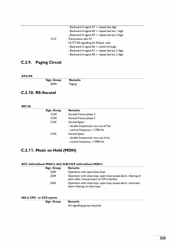
325
C.2.9. Paging Circuit
C.2.10. RS-Socotel
C.2.11. Music on Hold (MOH)
- Backward A signal A7 = repeat last digit- Backward A signal A8 = repeat last but 1 digit- Backward A signal A9 = repeat last but 2 digit
1512 Transmission plan 01CCITT-R2 signalling for Poland, with:- Backward A signal A6 = switch through- Backward A signal A7 = repeat last but 2 digit- Backward A signal A8 = repeat last but 3 digit
ATU-PASign. Group Remarks
3D04 Paging
RST-SLSign. Group Remarks
1C04 Socotel France phase 21C04 Socotel France phase 32104 Socotel Spain:
- double frequencies: two out of five- control frequency =1700 Hz.
2105 Socotel Spain:- double frequencies: two out of six- control frequency =1900 Hz.
ACC with/without MOH-I, ALC-A/B/C/E/F with/without MOH-ISign. Group Remarks
320E Operation with open/close loop2204 Operation with close loop, open loop causes alarm, clearing of
alarm after manual action on OM interface2205 Operation with close loop, open loop causes alarm, automatic
alarm clearing on close loop
IAS in CPS - or CCS systemSign. Group Remarks
No signalling group required

326
C.2.12. Music on COB
See Music on Hold
C.2.13. D-channel
C.2.14. Trunk circuit ISDN (TRC-ISDN)
IAS in CPU-ME/MTRemarks
See the table on page 303
IASARemarks
See the table on page 303
DTU-PH for DPNSS/DASS firmware (port number 16)Remarks
See the table on page 303
IPH-BRemarks
See the table on page 303
DTU-PH with 1TR6 firmwareSign. Group Remarks
5D04 User side, 1TR6 (PSI=H'03)5D05 Network side, 1TR6 (PSI=H'12)5D06 User side, 1TR6 (PSI=H'13)
DTU-PH for VN6Sign. Group Remarks
5D07 User side, VN6 (PSI=H'23)
DTU-PH for ETSISign. Group Remarks
5D08 User side, ETSI (PSI=H'31), Netherlands5D09 User side, ETSI (PSI=H'33), Belgium

327
C.2.15. Wake-up/MW Announcement Circuit
See Music on Hold
C.2.16. IAS-TS
5D0A User side, ETSI (PSI=H'37), Switzerland5D0B User side, ETSI (PSI=H'67), Germany5D0C User side, ETSI (PSI=H'35), Italy5D0D User side, ETSI (PSI=H'6B) for free numbers5D0E User side, ETSI (PSI=H'6D) for free numbers5D0F User side, QSIG (PSI=H'61) 5D10 Network side, QSIG (PSI=H'6B)
DTU-BA for 1TR6Sign. Group Remarks
5C04 User side, 1TR6, Germany5C05 Network side, 1TR6-tieline5C06 User side, 1TR6-tieline
DTX-I for 1TR6/ETSISign. Group Remarks
5C04 User side, 1TR6, Germany5C05 Network side, 1TR6-tieline5C06 User side, 1TR6-tieline5C0D User side, ETSI-Netherlands5C0E User side, ETSI-Belgium5C0F User side, ETSI-Switzerland5C10 User side, ETSI-Germany5C11 User side, ETSI-Italy5C12 User side, ETSI (PSI=H'6A) for free numbers5C13 User side, ETSI (PSI=H'6C) for free numbers5C14 User side, QSIG (PSI=H'60)5C15 Network side, QSIG (PSI=H'62)5C16 Network side, QSIG (PSI=H'64) via public
IAS with IAS firmwareSign. Group Remarks
See table C.1.

328
C.2.17. HATCH
PMCSign. Group Remarks
6104 Hatch

,
D. INDEX
AACTMML ......... 70ACTRBU.......... 79ASAPPF ........ 128ASBARR........ 114ASBLCK ........ 111ASBNDL ........ 197ASBRDS.......... 72ASBRVC.......... 77ASBSPB ........ 198ASBSPR........ 196ASCANS........ 106ASCONV ......... 30ASCRUE ......... 75ASCVCT.......... 30ASDEVC.......... 78ASDGCO....... 194ASDGCV ....... 194ASDICA......... 165ASEXSE .......... 47ASEXTN........ 113ASEXTP ........ 114ASFACM ......... 50ASFATI............ 53ASGECA ......... 63ASGRPM......... 64ASIABD ........... 87ASIBND........... 95ASILIN............. 95
ASINTN ......... 111ASLDNM.......... 82ASLINE.......... 199ASLINK............ 82ASPACD........ 125ASPALN ........ 126ASPCTB .......... 74ASPICC ......... 129ASPORT.......... 80ASPVNU........ 132ASSADN.......... 32ASSHLF........... 71ASTMOB ....... 181ASTMSD........ 148ASTMSW....... 148ASTMTI ......... 179ASTONE.......... 75ASTREE ........ 111
BBMLOCK ......... 14
CCALSIG ........... 55CANJOB.......... 25CANLDM ......... 99CHABNR ......... 11CHABNR ........... 5
CHACDD ......... 65CHACIV ......... 155CHAGCV ......... 12CHANNO ......... 91CHAQPR ....... 116CHASCV........ 119CHASOP........ 119CHASPR........ 120CHAUCO ....... 103CHBBUT........ 115CHBDNR ......... 40CHBDST.......... 73CHBDTU........ 198CHBNDC ....... 197CHBOUN ......... 20CHCALF .......... 23CHCASC........ 101CHCCTR ....... 195CHCDED ....... 199CHCLID ........... 44CHCOBD ......... 24CHCOMP......... 17CHCQPR ....... 116CHCSDD ....... 112CHCVAL .......... 29CHCVAP.......... 44CHCVCA.......... 29CHDEAU........ 156

,,
CHDEPR ....... 156CHDEVA ......... 81CHDFCM......... 51CHDNRC......... 39CHDNRS......... 12CHDSTC ....... 190CHFCMR....... 158CHFDNR ......... 45CHFKDA.......... 61CHFLME.......... 60CHFMSN....... 105CHFRCR ....... 169CHFROD....... 169CHGRDN......... 66CHHOOT....... 106CHHOTL.......... 86CHIABD........... 87CHIBNC........... 95CHINEX......... 107CHJOUR ......... 15CHMCNE....... 107CHMDNR ........ 62CHMQPR ...... 117CHMSNP....... 105CHNAME....... 104CHOPAV ....... 118CHOPDC......... 39CHOPTI........... 21CHOVEX ....... 107CHPAMD....... 126CHPANL........ 126
CHPARE........ 124CHPASS........ 157CHPATM ....... 160CHPCTB.......... 74CHPICC......... 129CHPLEX ........ 108CHPMPD....... 135CHPORT ......... 80CHPVND ....... 133CHPVNR ....... 131CHPVNS........ 133CHPVNT........ 132CHQLMR....... 117CHREMC....... 142CHRLOD ....... 146CHRORE......... 94CHROTA ....... 191CHRTCG ....... 193CHRTCI......... 193CHRTCO ....... 193CHSCNE ....... 107CHSEAU........ 156CHSEPR........ 156CHSJOB.......... 27CHSYSD........ 151CHTBAR........ 109CHTFCR........ 159CHTIME........... 21CHTMOD....... 180CHTMOF ....... 180CHTMSL........ 148
CHTMST........ 149CHTRFC........ 172CHTRLV ........ 167CHTRNE........ 107CHTTCR........ 167CHTTOD........ 167CHUNRE ......... 94CLALRM .......... 54CLPATC ........ 160CPYFIL ............ 57CRBSPT .......... 89CRCCPP........ 164CRCCSP........ 163CRCTYP:......... 30CRCVAL .......... 29CREFIL............ 57CRESGR ......... 48CREXSE.......... 47CRGRPA ......... 64CRPARE........ 124CRPART........ 125CRROUT ....... 192CRTWIN ........ 201
DDEBNDL ........ 197DEBRDS.......... 73DEBRVC.......... 77DECRUE.......... 76DEDEVC.......... 79DEDICA ......... 166

,,,
DEFATI............ 53DEGRPM......... 66DEIBND........... 95DEILIN............. 95DELDNM ......... 82DELFIL ............ 58DELINE ......... 199DELINK ........... 84DEOVLM ....... 123DEPACD ....... 126DEPACK.......... 43DEPALN........ 126DEPCTB.......... 75DEPORT ......... 81DEPVNU ....... 132DESHLF .......... 72DETEST ........ 161DETMOB....... 181DETMTI ......... 179DETONE ......... 75DIABNR........... 11DIACIV .......... 155DIAGCV........... 12DIANNO .......... 92DIAPPF ......... 128DIAQPR......... 116DIASCV......... 119DIASOP......... 119DIASPR......... 120DIAUPR......... 156DIBARR......... 114
DIBBUT ......... 115DIBDNR........... 41DIBDTU ......... 199DIBLCK............ 54DIBNDL ......... 197DIBRDS........... 74DIBSPB ......... 198DIBSPR ......... 196DIBSPT............ 89DICALF............ 23DICANS......... 106DICASC......... 102DICCDI .......... 165DICCRT......... 196DICCSS......... 141DICCTR......... 196DICDNR........... 40DICHAR........... 79DICLID............. 44DICOBD........... 24DICOCO ........ 164DICOMP .......... 18DICONF........... 71DICONV........... 30DICQPR......... 117DICRUE........... 76DICSDD......... 112DICTYP ........... 31DICVAL............ 29DICVAP ........... 45DICVCA........... 29
DICVCT ........... 31DIDATI............. 34DIDEST ......... 191DIDEVC ........... 80DIDFCM........... 51DIDGCO ........ 194DIDIAL ........... 113DIDICA .......... 166DIDILA ............. 36DIDNRC........... 40DIDNRM .......... 62DIDNRS........... 13DIESGR........... 49DIEXID:............ 34DIEXSE............ 47DIFACM........... 50DIFATI ............. 53DIFCMR......... 159DIFCSU ........... 50DIFDNR........... 46DIFKDA ........... 61DIFLME ........... 60DIFMSN......... 105DIFROD......... 169DIGECA........... 63DIGRPA........... 66DIGRPM .......... 67DIGRPS........... 67DIHIBU ............ 55DIHOTL ........... 86DIIABD............. 87

,9
DIIBND ............ 95DIIROU............ 96DILICS............. 97DILINE........... 199DILINK............. 85DIMAJA ........... 54DIMDAT......... 101DIMDNR.......... 62DIMEMQ........ 162DIMERE .......... 38DIMINA............ 55DIMMFC........ 101DIMQPR........ 117DIMSNP ........ 105DINAME ........ 104DINARS......... 109DINASD......... 110DINASM ........ 110DIOPAC......... 121DIOPAV......... 118DIOPCT......... 122DIOPID.......... 121DIOPLD......... 121DIOPST......... 121DIOVLD......... 100DIOVLM......... 123DIPACK........... 43DIPALN ......... 126DIPARE......... 124DIPART ......... 125DIPATC ......... 160
DIPICC .......... 129DIPLPO ........... 68DIPMPD......... 137DIPOOL......... 171DIPORT........... 81DIPVNR......... 131DIPVNT ......... 133DIPVNT ......... 134DIPVNU......... 132DIQLMR......... 118DIRECT ........... 58DIRLOD......... 146DIROCO ........ 171DIROTA......... 191DIROUT......... 192DISADN........... 32DISEMD......... 120DISERV ......... 138DISHLF............ 72DISILA ............. 55DISJOB............ 26DISLDM........... 99DISPEX ......... 108DISPFR ......... 170DISPRL.......... 147DISPTM......... 179DISPTO ......... 181DISPTT.......... 168DISYSD ......... 152DITCRT ......... 200DITEST.......... 161
DITFCR ......... 159DITFKM ........... 61DITMOB......... 181DITMOD ........ 180DITMOF......... 180DITMSD......... 149DITMSL ......... 149DITMST ......... 149DITMSW ........ 150DITMTI........... 180DITRAF.......... 174DITRFC ......... 172DITRLV.......... 167DITTOD ......... 168DITWIN.......... 201DIUNIT........... 205DIURRE........... 94DIVICH .......... 139DOWNLD ........ 42DUSYSD........ 152
EERAPPF ........ 128ERBARR........ 114ERBSPB ........ 198ERBSPR........ 196ERCANS........ 106ERCOCO....... 164ERCONV ......... 31ERCTYP .......... 31ERCVAL .......... 30

9
ERDGCO....... 194ERDGCV....... 194ERDILA: .......... 37ERESGR ......... 49EREXSE.......... 48ERFACM ......... 51ERGECA ......... 63ERGRPA ......... 69ERIABD........... 87ERPARE........ 125ERPART........ 125ERPICC......... 129ERROUT ....... 192ERSADN ......... 33ERSYSD........ 153ERTMLI ......... 181ERTWIN........ 201EXSJOB .......... 27
FFIPCTT............ 75FISERV ......... 139FRCOUT ....... 140
GGEBUMI .......... 16GUIDNC .......... 70
IINESGR........... 49INIDSK ............ 90
INSTPK............ 42INTEST.......... 161
LLDOVLM........ 123
MMAKENU ....... 111MOVFIL ........... 59
OOMLOCK......... 15
PPUBUMI........... 16PURFIL............ 58
RREOVLM ....... 123REROUT ......... 56RESJOB .......... 26RTRIEV ........... 15
SSECCDI ......... 165SECCTO........ 164SEDATI............ 35SEOVLM........ 123SETINS.......... 140SETNIN ......... 140SETOUT........ 141
SPDUAL ........ 204STALDM .......... 99STCOLD........ 203STDUAL ........ 204STLOAD ........ 203STOPFR........ 170STOPRL ........ 147STOPTM........ 179STOPTT ........ 169STPROJ ........ 203STRTFR ........ 170STRTRL......... 146STRTTM........ 179STRTTT......... 168STWARM....... 204SUBJOB .......... 26SUSJOB .......... 27SWALEX.......... 55SWDUAL ....... 204SWJUPD ......... 16SWMMLV ........ 70
TTRSYSD ........ 153TSALRM ........ 162TYPFIL ............ 59
UUNIINS .......... 205UNININ .......... 205UPDATE .......... 17
