omega ep vol vii (beamlines) - university of rochesteropto-mech.lle.rochester.edu/training...
TRANSCRIPT

OMEGA EP Vol VII (Beamlines)
Outline
I. Beamlines DescriptionII. Beamlines Subsystems, including diagnosticsIII. Conclusions
The goal of this training is to improve the communi cation between operators, and to improve the flow and quality of d ata
The functional requirements of OMEGA EP beamlines are:
• Transport pulse from Laser Sources through amplifie rs• Temporally compress IR beam (short-pulse operation)• Frequency convert IR to UV (long-pulse operation)• Transport beams to target chamber• Focus beams on target• Diagnose properties of on-shot laser pulses
The beamlines group members are the photon plumbers of the operations division. We move light from the front-end to the target chamber and we
have lots of options.

• Short-pulse 1 ωωωω [1053 nm] (Beamlines 1-2)– 2.6 kJ energy on target, 10 ps (0.26 PW), 20 micron diameter spot (80%
encircled energy)– 1-100 ps temporal pulse width– Capability to provide 10 12 W (1 PW) to target
• Long-pulse 3 ωωωω [351 nm] (Beamlines 1-4)– 5 kJ energy on target, 1-10 ns
• Beam size 369-mm-square @ 1% intensity level– Apodization/beam shaping applied by Laser Sources
• Laser damage threshold up to 20 J/cm^2– Compressed pulse limits fluence for short-pulse– 3ωωωω LDT limits fluence for long-pulse
Optical components for use on the National Ignition Facility (NIF) are used where appropriate (acquired from LLNL)
Custom optical components designed at UR/LLE and fa bricated by selected vendors (Zygo, Tinsley, Jobin-Yvon, LLNL)
OMEGA EP optical components are specified to meet top-level performance requirements

OMEGA EP was designed to be an extremely well diagnosed laser system
• There are four major diagnostic packages in the Las er Bay– IRAT/Injection– IRDP– SPDP– UVDP
• Energy is a major issue when it comes to building a diagnostic package in the Beamlines section
– High transmission is great for alignment– Low transmission is great for on-shot– Energy balance between diagnostics was a design foc us for some of the
diagnostic packages
It is hard to get rid of energy in a safe way witho ut changing the beam.

Large Laser System Design: Collimation and Imaging
• Large laser systems have three constraints :– The laser is collimated in areas where there is amp lification or long
propagation distances.• Collimated beam sizes are selected to avoid damagin g fluences or
nonlinear effects.– Images planes are placed at areas where phase to am plitude errors are an
issue (In EP: Cavity DM, G4, FCC, etc.).– After every stage of amplification the beam must be spatially filtered to
remove high-spatial-frequency noise in the beam.• EP has lots of image planes (RP#)
– RP0 is defined as the system cross hair, which is l ocated on the IRAT. Negative numbers are in laser sources bay, positive numbers are in the laser bay.
– The “ideal” object is the Laser Sources apodizer.
Numerous diagnostics require a system image plane a nd collimated beam to function properly.
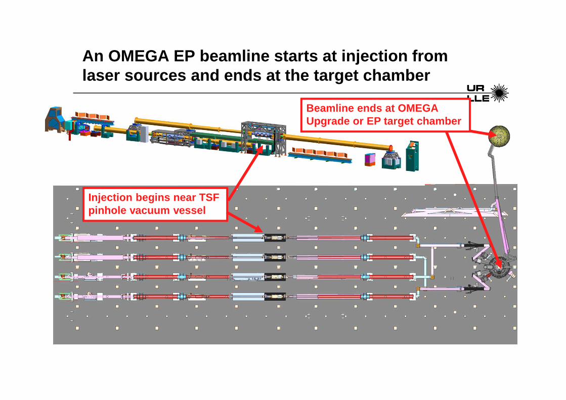
An OMEGA EP beamline starts at injection from laser sources and ends at the target chamber
Injection begins near TSF pinhole vacuum vessel
Beamline ends at OMEGA Upgrade or EP target chamber

11-disk AMP
7-disk AMP
Omega TC
Grating Compressor Chamber
Long-Pulse UV
NIF OpticsLLE Optics
Main Laser Beamline
Omega EP TC
IR Switchyard
Omega Target Bay
Short-Pulse Diagnostic Path
IRHR3
VW
TGA3TGA2
TGA1
BC
SPHR1
SPHR3
SPHR2
SL-OAP
SPHR6
SPHR5
TGA4
SPHR4
SPOL2 SPOL1
POL
SW2 SC SW1
IRHR1
CEM
TSF1BA1 - BA7
IRHR2
CFM TSF2
CSF2 CSF1
IR-DBS
MA11 - MA1 DM1
DM2
The OMEGA EP beamlines equipment can be grouped by function into 5 distinct areas
SPHR9
SPHR11
OAP
BL-OAP
SPHR10
SPHR12
SPHR13SPHR14
SPHR7SPHR8
IRHR5IRHR6
IRHR4
VW
FCCs
UV-DBS
UV HR1
UV-FL
UV HR2

Short-Pulse [Beamlines 1-2, <1-100 ps]Stretched pulses from OPCPA front-end are:• Amplified• Routed to compressor chamber • Combined (optional for backlighter use) into single beam• Transported to OMEGA Upgrade or EP target chamber• Focused to target using an off-axis parabola (OAP)
Long-Pulse [Beamlines 1-4, 1-10 ns]OMEGA Upgrade-style front-end pulses leave main las er and
are: • Frequency converted to 3 ωωωω• Transported to the OMEGA EP target chamber• Focused to target
The beamlines are designed to accommodate two possible modes of operation

11-disk AMP
7-disk AMP
Omega TC
Grating Compressor Chamber
Long-Pulse UV
NIF OpticsLLE Optics
Main Laser Beamline
Omega EP TC
IR Switchyard
Omega Target Bay
Short-Pulse Diagnostic Path
IRHR3
VW
TGA3TGA2
TGA1
BC
SPHR1
SPHR3
SPHR2
SL-OAP
SPHR6
SPHR5
TGA4
SPHR4
SPOL2 SPOL1
POL
SW2 SC SW1
IRHR1
CEM
TSF1BA1 - BA7
IRHR2
CFM TSF2
CSF2 CSF1
IR-DBS
MA11 - MA1 DM1
DM2
The short pulse beam path includes the main amplifier, IR switchyard, GCC, IR transport, and focusing
SPHR9
SPHR11
OAP
BL-OAP
SPHR10
SPHR12
SPHR13SPHR14
SPHR7SPHR8
IRHR5IRHR6
IRHR4
VW
FCCs
UV-DBS
UV HR1
UV-FL
UV HR2

11-disk AMP
7-disk AMP
Omega TC
Grating Compressor Chamber
Long-Pulse UV
NIF OpticsLLE Optics
Main Laser Beamline
Omega EP TC
IR Switchyard
Omega Target Bay
Short-Pulse Diagnostic Path
IRHR3
VW
TGA3TGA2
TGA1
BC
SPHR1
SPHR3
SPHR2
SL-OAP
SPHR6
SPHR5
TGA4
SPHR4
SPOL2 SPOL1
POL
SW2 SC SW1
IRHR1
CEM
TSF1BA1 - BA7
IRHR2
CFM TSF2
CSF2 CSF1
IR-DBS
MA11 - MA1 DM1
DM2
The long pulse beam path includes the main amplifier, IR switchyard, and UV transport/focusing
SPHR9
SPHR11
OAP
BL-OAP
SPHR10
SPHR12
SPHR13SPHR14
SPHR7SPHR8
IRHR5IRHR6
IRHR4
VW
FCCs
UV-DBS
UV HR1
UV-FL
UV HR2

11-disk AMP
7-disk AMP
Omega TC
Grating Compressor Chamber
Long-Pulse UV
NIF OpticsLLE Optics
Main Laser Beamline
Omega EP TC
IR Switchyard
Omega Target Bay
Short-Pulse Diagnostic Path
IRHR3
VW
TGA3TGA2
TGA1
BC
SPHR1
SPHR3
SPHR2
SL-OAP
SPHR6
SPHR5
TGA4
SPHR4
SPOL2 SPOL1
POL
SW2 SC SW1
IRHR1
CEM
TSF1BA1 - BA7
IRHR2
CFM TSF2
CSF2 CSF1
IR-DBS
MA11 - MA1 DM1
DM2
Injection Optics mark the start of a main beamline
SPHR9
SPHR11
OAP
BL-OAP
SPHR10
SPHR12
SPHR13SPHR14
SPHR7SPHR8
IRHR5IRHR6
IRHR4
VW
FCCs
UV-DBS
UV HR1
UV-FL
UV HR2
Injection Subsystem

Injection & IRAT Tables
IRAT Table
Injection Table
Periscope
N
TSF Vacuum Vessel & Support
Structure

Upgrades to the IRAT and Injection tables started i n September of 2010, with numerous goals

Vacuum Window
Injection Lens
Injection Fold Mirror
Fold Mirror
Pointing/Centering Mirrors
Image relay
TSF Vacuum Vessel
Pass-1 Pinhole
Pass-4 Pinhole TSF Pinhole Assembly
From Laser Sources
Injection optics receive a collimated beam from las er sources and focus it through the TSF Pass-1 pinhole
RP0
To Main Laser
Main Beamline Setup - Options
• 2 Pass or 4 Pass• Short-Pulse or Long-Pulse• SP-Pols in or out• PEPC
– Single pulse – Double pulse
• OPCPA to SPDP– 5 Hz– 0.1 Hz
What does this all mean? Why does it matter? How does it affect beamline alignment

Main Beamline Alignment – 2 Pass, PEPC is off
CEMTo
IRDBSCav. Pol
SP-Pol
CFM

Main Beamline Alignment – 4 Pass, PEPC is on
CEM
CFM
Cav. PolTo
IRDBS

Main Beamline Alignment
Pinhole viewing system image
Goal: Aligning beam to pinhole on each pass
How: Use a different mirror to align to passes 1 - 3.
• TSF Pass 1: Injection pointing mirror
• CSF Pass 1: Cavity Polarizer
• CSF Pass 2: Cavity DM
• CSF Pass 3: Cavity End Mirror
Because of the geometry of the system, if pass 4 is off, the only way to fix it is to start over again with pass 1.

What about centering in the Main Beamline?
There are three adjustments for centering in the Ma in Beamline
1. Sources pointing & centering mirrors on the IRAT• Used daily to align Source x-hair (RP-1) to System x-hair (RP0)
2. Injection pointing & centering mirrors (after Inj . NF)• Used as required to align System x-hair (RP0) to TS F x-hair• Injection lens/TSF south lens has 6.3x magnificatio n
3. Cavity Fold Mirror• Used as required to align TSF x-hair to DM X-hair

The PEPC is a full aperture Pockels cell. It is ke y to multi-pass laser amplifier systems (EP, NIF & JML).
Plasma Electrode Pockels Cell (PEPC)• Switching contrast >500:1 over entire CA• Switching time <100ns• Base pressure <5 x 10⁻⁵ Torr• Processed gas is 99% helium and 1%
oxygen• Automatic changeover between process
gas tanks without pressure drop• Two modes: Single & Double Pulse • Double Pulse: Switches the polarization of
any target retros

Main Beamline Alignment: Short-pulse vs. Long-pulse
• Long-Pulse– All alignment is done with the IRAT– No SP-polarizers– CSF waveplates allow transmission through Cavity-Pol arizer on
Pass 2 and transmission through main amps on Pass 3• Short-pulse
– Alignment is done with the SP-polarizers inserted• Requires OPCPA (Source’s beam*) • Alignment for passes 3 and 4 is done at 0.1 Hz
*IRAT upgrades will remove this requirement

Main Beamline - Shot Configurations
System Mode Shot Type PEPC SP-Pols
BL 1 & 2
Short Pulse
4 & 5 Single Pulse In
7 Double Pulse In
Long Pulse 4-6 Single Pulse Out
BL 3 & 4 Long Pulse 4-6 Single Pulse n/a

How is the Main Beamline setup?
Laser sources request for best compression search?• 5hz OPCPA to SPDP: SP-Pols out, CSF waveplates inSource pre-shot timing measurement on SPDP?• 0.1hz OPCPA to SPDP: SP-Pols in, CSF waveplates outIRAT to SPDP?• SP-Pols out, CSF waveplates inIRAT to UVDP?• SP-Pols out, CSF waveplates inLaser sources request for SPDP ROSS alignment check s?• During maintenance?• 5hz OPCPA to SPDP: SP-Pols out, CSF waveplates in• During Shots?• 0.1hz OPCPA to SPDP: SP-Pols in, CSF waveplate outBL3 & 4 PEPC Timing?• LARA in bypass, 4-pass, CSF waveplates in

Daily shot plans
Shot Goal
Type 3 Energy centration to RP0
Type 4D Pulse width measurement
Type 5D/7 (40/250J) Gain narrowed pulse measurement at low energy
Type 5D/7 (Full Energy)
Shot Goal
Type 3 Energy centration to RP0Verify injection energy
Type 4A Verify injection pulse shapeDiagnostic check out
Type 5C/6
Short-Pulse
Long-Pulse
On all shots we should be looking at energy, spatia l profile and wavefront
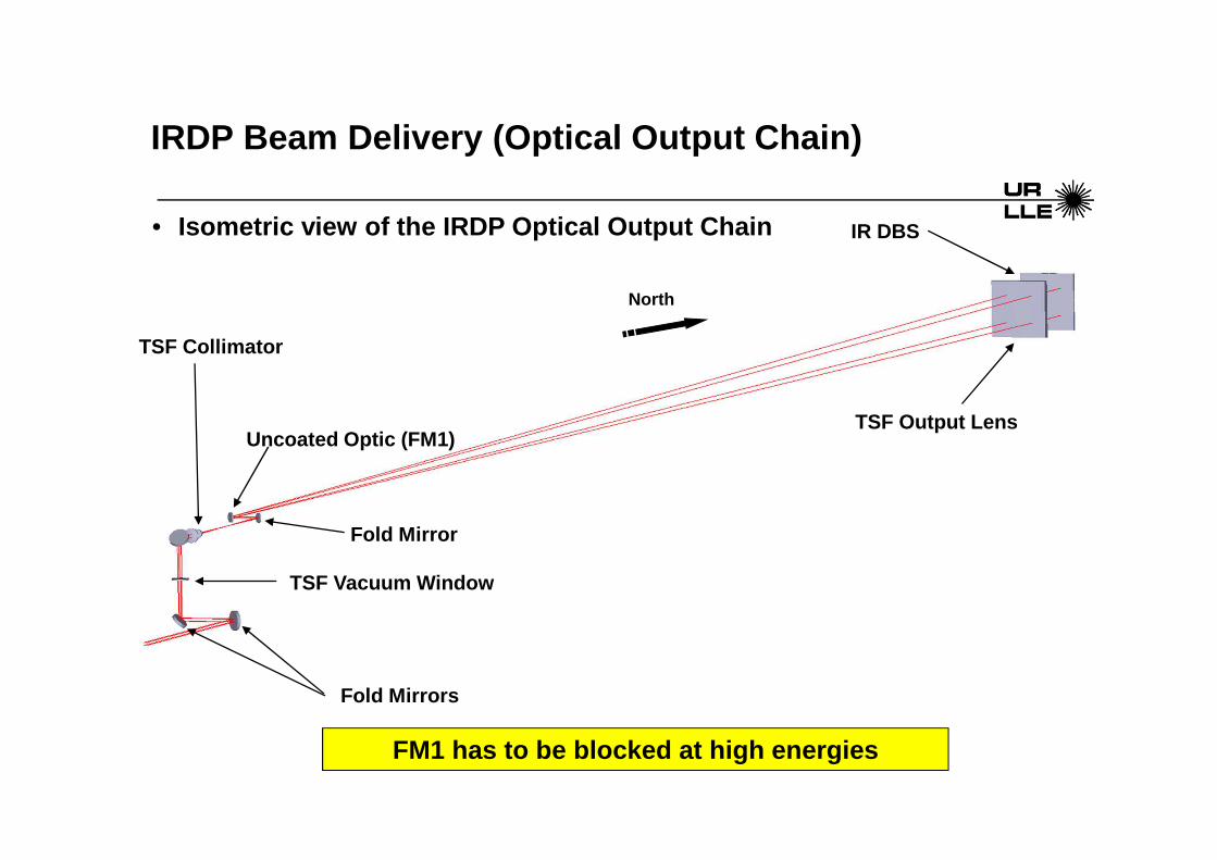
• Isometric view of the IRDP Optical Output Chain
IRDP Beam Delivery (Optical Output Chain)
Uncoated Optic (FM1)
TSF Vacuum Window
IR DBS
TSF Output Lens
Fold Mirror
TSF Collimator
Fold Mirrors
North
FM1 has to be blocked at high energies

27
IRDP Table Layout
Energy Diagnostic
Far FieldASP Centering
Fiber Launchers (Streak camera, Spectrometer)
Diagnostic Beam Pickoffs
Wavefront Control Sensor
Optics Inspection
Near Field
ASP Pointing
Input Beam

Main Beamline Diagnostics
• All beamline shots (SP and LP)– Inj. ED– Inj. And IRDP NF– IRDP FF (BL2 only)– IRDP WFS– IRDP HASO (currently OOC)– Inj. Cal (only SP, when LS amp is fired)
• Short-pulse Only– Inj. And IRDP Spectrometer
• Long-pulse only– Inj. And IRDP ROSS

NF Images - normal
x [pixel]
y [p
ixel
]
NF Inj
-500 0 500-500
0
500
0
200
400
600
800
x [pixel]y
[pix
el]
NF IRDP
-500 0 500-500
0
500
0
1000
2000
3000
BL4, Shot # 3609, 511J to SY Cal
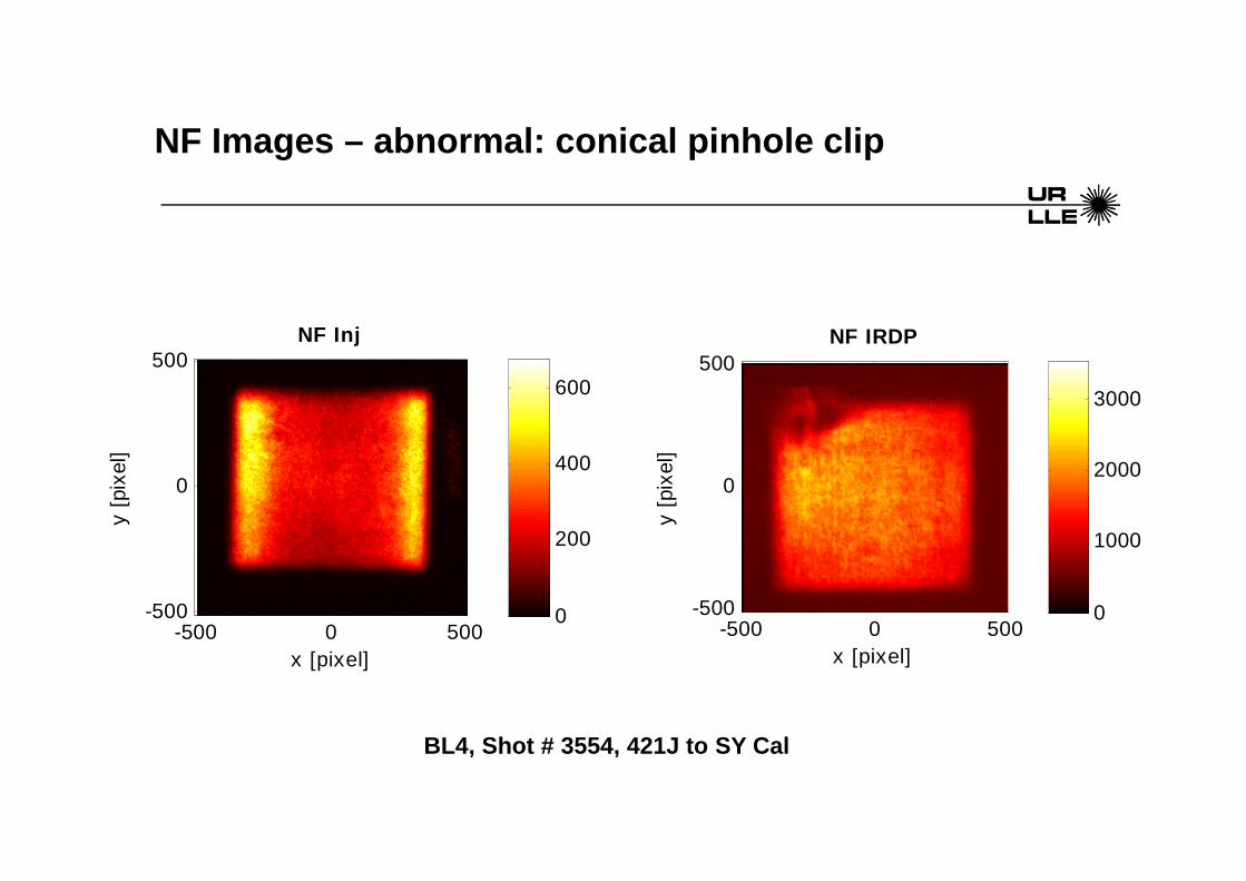
NF Images – abnormal: conical pinhole clip
x [pixel]
y [p
ixel
]
NF Inj
-500 0 500-500
0
500
0
200
400
600
x [pixel]y
[pix
el]
NF IRDP
-500 0 500-500
0
500
0
1000
2000
3000
BL4, Shot # 3554, 421J to SY Cal

Energy Data: Shot # 3754 cont.
OMEGA EP SHOT REPORT FOR BEAMLINE 1 Log Number: 3754
Shot Date: 30-Jul-2008 12:02:37 Shot Type: Beamline
Template #: 434 Shot Status: System Shot
Sources Spot Mode Name Spot Counts Energy ==== ===== ====================== =========== ============= 98 SHORT REGEN Output 99540 6.2293 mJ 87 SHORT CLARA input 122156 5.2707 mJ 89 SHORT CLARA output 45156 1.2689 J 80 SHORT SHG output 533 0.0158 J 38 SHORT OPCPA: S1 8302 0.1417 mJ 29 SHORT Pump residual, S1 14741 0.0751 mJ 18 SHORT OPCPA: S2 10033 524.6019 mJ 47 SHORT Pump Residual, S2 517 517.0000 mJ 9 SHORT OPCPA Output (after SF) 4090 4090.0000
mJ 69 SHORT Glass Amp Input 5028 16.8552 mJ 58 SHORT Source Output 14574 14574.0000 mJ Beamlines Spot Mode Name Spot Counts Energy ==== ===== ====================== =========== ============= 49 SHORT Beamline Injection 213354 0.5004 J 70 SHORT IRDP 522 522.0000 kJ20 SHORT Compressor Output 54692 306.8779 J

Cal Trace – abnormal: Max cal energy set too low
BL1 Shot #1167

Wavefront Control System - WCS
• Control of the deformable mirrors (DM) allows for t he correction of static and dynamic wavefront errors.
• Additionally, the cavity DM pre-compensates for pro mpt induced distortion (PID) in the amplifiers
• All of the DMs in the system work well on low spati al frequencies, but can not correct high spatial frequencies.
• >1/4 of the DM stroke is taken up by correcting the DM itself.• The DM itself causes some of the focal spot issues that EP has, but without it
we wouldn’t be able to consider focal spots close t o 50 microns.

Correction MTF of DM
0
1
2
3
4
5
6
7
8
9
10
0.00 0.02 0.04 0.06 0.08 0.10
Spatial Frequency (cm -1)
Cor
rect
ion
Ran
ge (
wav
es @
106
4 nm
)
Cos(x)
Cos(y)
Influence Fn FFT
The DM correction falls off with spatial frequency about as predicted, except for very low frequency
Larger than expected correction at ½ cycle is
likely due to the fact that the mirror is not
constrained beyond the outer actuators.
i.e. Outer actuators have larger stroke, and the effect
is strong near ½ cycle across mirror.
f = 1/15 cm -1
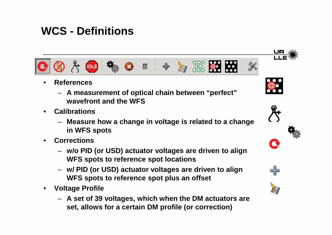
WCS - Definitions
• References– A measurement of optical chain between “perfect”
wavefront and the WFS• Calibrations
– Measure how a change in voltage is related to a cha nge in WFS spots
• Corrections– w/o PID (or USD) actuator voltages are driven to al ign
WFS spots to reference spot locations– w/ PID (or USD) actuator voltages are driven to ali gn
WFS spots to reference spot plus an offset• Voltage Profile
– A set of 39 voltages, which when the DM actuators a re set, allows for a certain DM profile (or correction )

Static Wavefront Corrector - SWC
Each beamline has a slightly different phase correc tor, due to the differences in the DMs and other large optics in ea ch beamline

SWC is a single optic that will be installed just p rior to the beam leaving the IRAT table
RP0
Static Wavefront Corrector
Injection
North

Correction of the EP wavefront need to be done a cl ose to shot as possible.
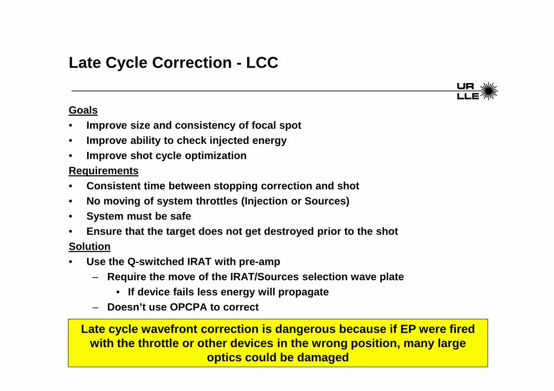
Late Cycle Correction - LCC
Goals• Improve size and consistency of focal spot• Improve ability to check injected energy• Improve shot cycle optimizationRequirements• Consistent time between stopping correction and sho t• No moving of system throttles (Injection or Sources )• System must be safe• Ensure that the target does not get destroyed prior to the shotSolution• Use the Q-switched IRAT with pre-amp
– Require the move of the IRAT/Sources selection wave plate• If device fails less energy will propagate
– Doesn’t use OPCPA to correct
Late cycle wavefront correction is dangerous becaus e if EP were fired with the throttle or other devices in the wrong pos ition, many large
optics could be damaged
Other things that you need to know about the Main Beamlines
• Gapodizer (BL1&2 only)– A NF mask to block the TGA gaps– Currently located at the cavity end mirror (CEM)– Future location is near RP0 on IRAT
• NT0D Shutter (BL1&2 only)– Shutter to block OPCPA until after T-10– Closes automatically post shot
• Switch Yard (BL1&2)– Short Pulse requires the IRHR1 & 2 install– Long Pulse requires the IRHR1 & 2 removed– Installation & removal of IRHR1 & 2 is crane operat ion
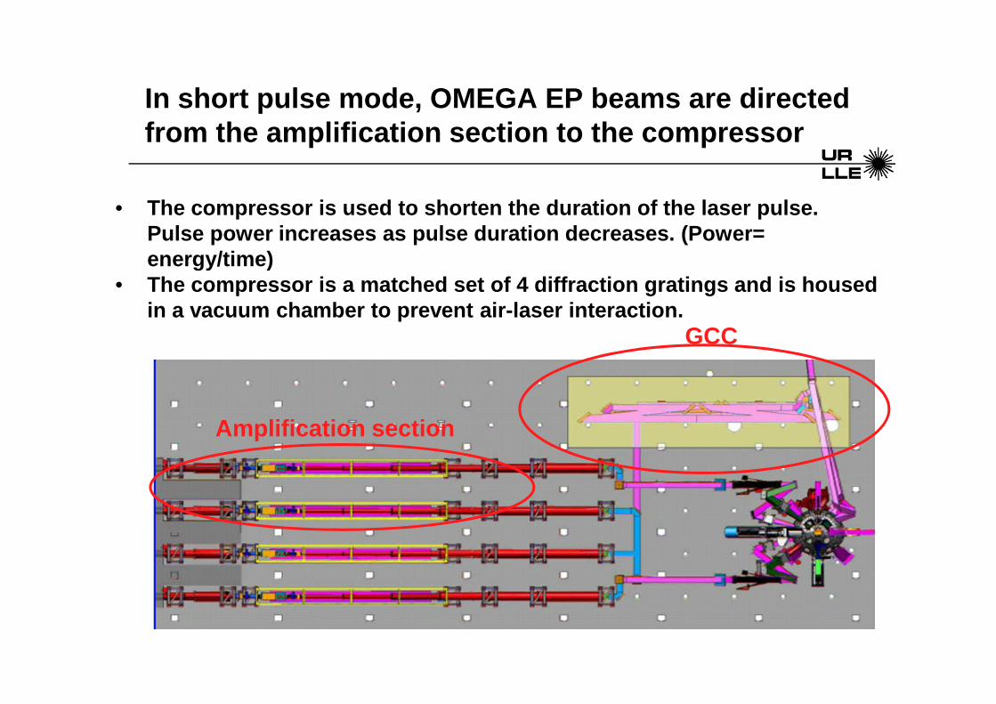
• The compressor is used to shorten the duration of t he laser pulse. Pulse power increases as pulse duration decreases. (Power= energy/time)
• The compressor is a matched set of 4 diffraction gr atings and is housed in a vacuum chamber to prevent air-laser interactio n.
GCC
In short pulse mode, OMEGA EP beams are directed from the amplification section to the compressor
Amplification section

Why Do We Use a Compressor?
1: Initial seed pulse (in laser sources)
2: Stretched pulse (injected into beamline)
3: Amplified stretched pulse (after beamline)
4: Compressed pulse (after GCC)
Amplifier Damage
Threshold
• To achieve high on-target power while staying below the amplifier damage threshold.

There are four beam paths in the GCC
• Tiling• Alignment• On Shot• Diagnostic

TilingDiagnosticOn Shot Alignment
Inside the GCC looking north
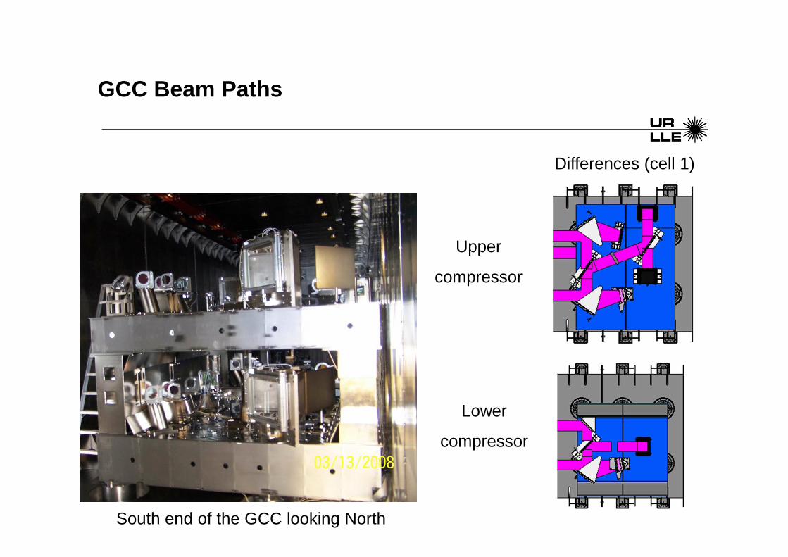
GCC Beam Paths
Upper
compressor
Lower
compressor
Differences (cell 1)
South end of the GCC looking North

The CAMs and periscopes allow for us to compressor alignment
Cam1 (inserted)
South Periscope(inserted)
North Periscope(out)
Cam2 (out)
Cam3 (out)
CAM= Compressor Alignment Mirror

Periscopes and Reference Beam Splitter
• The periscopes, together with the reference beam sp litter, are used as a fixed pointing reference for the GCC.
• With the periscopes inserted, a portion of the inpu t beam is picked off by the north periscope, passed through t he reference beam splitter, then passed behind the TGAs to the s outh periscope.North Periscope South Periscope
50/50 Beam Splitter
50/50 Beam Splitter

A set of transport mirrors deliver the short pulse beam to either OMEGA Upgrade or EP target chambers

An off-axis parabolic mirror is used to focus the short pulse beam to target
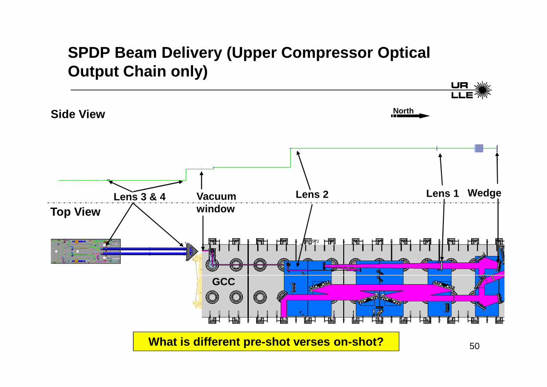
50
North
Top View
Side View
Vacuum window
Lens 2 Lens 1 WedgeLens 3 & 4
GCC
SPDP Beam Delivery (Upper Compressor Optical Output Chain only)
What is different pre-shot verses on-shot?

SPDP Table
ASPDM WFS
FSD
Far Field
Near Field
Spectrometer
UTD
• The upper and lower compressed beams each see a ded icated suite of diagnostics.
• The SPDP also includes a multi-function alignment s ource.
North

52 of 33 April 07, 2010 D-AA-M-850
High Contrast Diagnostic – HCD
SPDP table HCD table Non-shot path
On-shot path
LC
UC

Short-Pulse Diagnostics
• UC and LC Diagnostics (Two sets)– GCC Calorimeter (Type 5d shots only)– SPDP NF and FF– SPDP WFS– Focal Spot Diagnostic– HCD Table Diagnostics
• Energy Meter• Spectrometer• Diode• Single Shot Cross Correlator - SSCC
• UC or LC Diagnostics (One set with selection mirror )– SPDP ROSS– TESSA

Pulse Width Measurement on SPDP
On-Shot – Ross vs. Tessa• ROSS
– For shots: Use on 10ps-100ps– Images taken pre-shot to check signal level AND tim ing
• TESSA– For shots: Use only on best compression shots– Used during best compression search– Images taken pre-shot to check signal level
Best Compression Search• SAC
– 5hz measurements• TESSA

SI800 Images: BL1 SP
x [pixel]
y [p
ixel
]
NF Inj
-500 0 500-500
0
500
0
500
1000
1500
x [pixel]
y [p
ixel
]
NF IRDP
-500 0 500-500
0
500
0
1000
2000
3000
x [pixel]
y [p
ixel
]
FF IRDP
-500 0 500-500
0
500
0
200
400
x [pixel]
y [p
ixel
]
NF LC
-500 0 500-500
0
500
0
500
1000
1500
x [pixel]
y [p
ixel
]
FF LC
-500 0 500-500
0
500
0
1000
2000

Other things that you need to know about the Short Pulse
• PAD – Parabola Alignment Diagnostic– TIM based diagnostic– Used weekly for aligning the OAPs and doing FSD cal ibrations
• FSM – Focal Spot Microscope– TIM based diagnostic – Measures short pulse focal spot at low energy – Used for validation of FSD measurements

In long pulse mode, IR beams are transported to frequency conversion crystals (FCC’s)
• FCC’s are located after the main amplification sect ion of the beamline, but before transport to the target chambe r.
• They are used to convert the amplified IR laser pul se into the UV light that will interact with the target.
Amplification cavity
Conversion crystals

Steering mirrors and a focusing assembly bring the long pulse beams to target similar to OMEGA Upgrade
End of main laser
FCC’s
End Mirror
Target Mirror
Focus lens assembly

FCC’s
UVDP OAP
DPP Mount (BL4 Only)
UV DBS
On-shot pickoff
On-Shot Diagnostics Beam Path
Isometric View
North
UVDP Beam Delivery (Optical Output Chain)
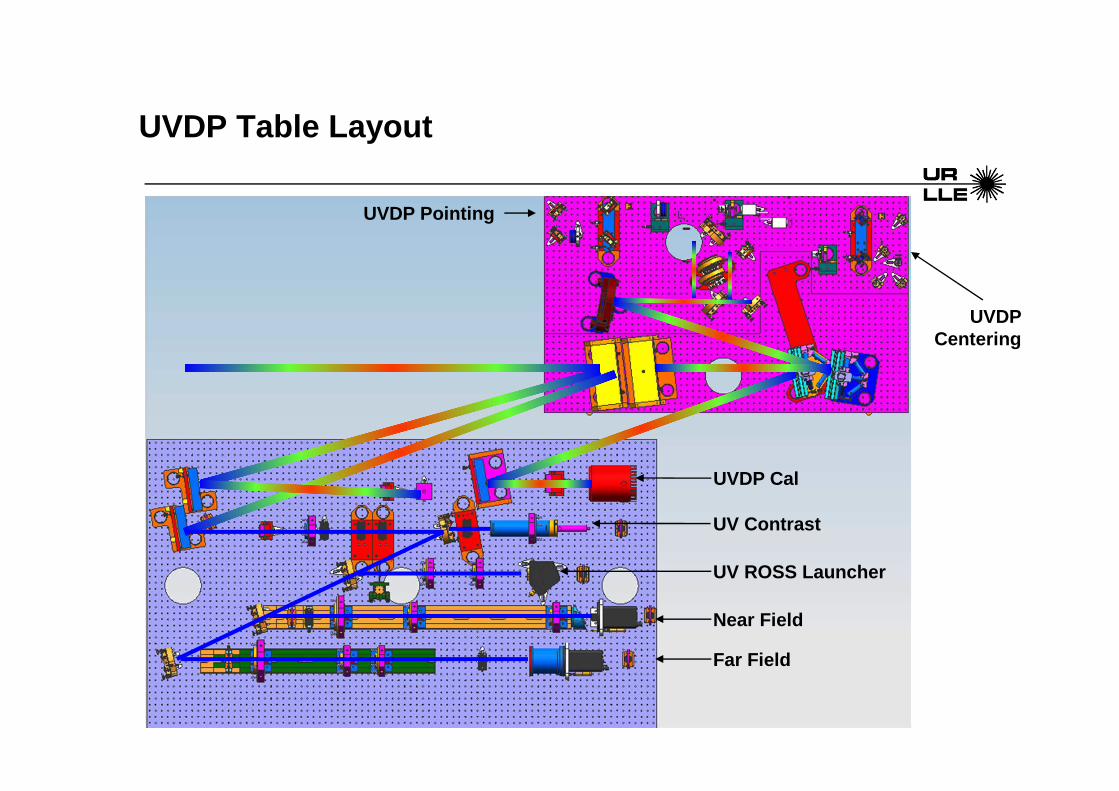
UVDP Table Layout
Far Field
Near Field
UV ROSS Launcher
UV Contrast
UVDP Cal
UVDP Pointing
UVDP Centering

Long-Pulse Diagnostics
• UVDP Diagnostics– UVDP Calorimeter (All beamlines)– UVDP NF (All beamlines)– UV ROSS (All beamlines)
• Controlled by Laser Sources• Our only job is to set filtration per the SRF
– UVDP FF (BLs 3 and 4 only)– Contrast Diagnostic (currently BL3 only)– Harmonic Energy Diagnostic (HED)
• One integrating sphere* on each beamline, all feed into one camera in the diagnostic bay
* Although it is not functional yet, the UV Spectro meter will be fed by the HED integrating sphere

SI800 Images: BL3 LP
x [pixel]
y [p
ixel
]
NF Inj
-500 0 500-500
0
500
0
1000
2000
3000
x [pixel]
y [p
ixel
]
NF IRDP
-500 0 500-500
0
500
0
5000
10000
15000
x [pixel]
y [p
ixel
]
NF UV
-500 0 500-500
0
500
0
2000
4000
6000
8000
x [pixel]
y [p
ixel
]
FF UV
-500 0 500-500
0
500
0
2000
4000
6000
8000
10000
Conclusions
The OMEGA EP beamlines:
• Bring beams up to required energy and full aperture• Compress IR beams (SP) or convert IR to UV (LP)• Transport beams to target chamber• Focus beams on target • Diagnose properties of on-shot laser pulses