omega gasturbine flowmeters
TRANSCRIPT


-1-
CONTENTS 1. Introduction --------------------------------------------------------------- 2 2. Specifications (Turbine)------------------------------------------------- 3 3. Specifications (Transmitter)-------------------------------------------- 4 4. Model Number ------------------------------------------------------------ 5 5. Principal of Operation--------------------------------------------------- 6
Signal Transmitter ------------------------------------------------------- 7 Material Selection and Construction ---------------------------------- 8 Flowmeter Calibrations ------------------------------------------------- 8
6. Installation ----------------------------------------------------------------- 9 7. Transmitter Wiring ----------------------------------------------------- 11
Flowmeter Input -------------------------------------------------------- 12 Analog Output----------------------------------------------------------- 13 Alarm Output------------------------------------------------------------ 14 RS232 Communications Port------------------------------------------ 16
8. Maintenance and Troubleshooting----------------------------------- 17 Pickup Coil Testing----------------------------------------------------- 17 Bearing Testing --------------------------------------------------------- 17 Bearing Replacement--------------------------------------------------- 18
9. Communication Protocols --------------------------------------------- 19 Message Format and Timeout----------------------------------------- 19 Messages----------------------------------------------------------------- 21

-2-
1. Introduction
The following information is provided for the proper installation and maintenance of your instrument.

-3-
2. Specifications (Turbine)
Over-range: 150% of maximum flow (intermittently)
Turn Down Range: Dependent on gas density at user’s operating conditions.
Linearity: ±1% of reading typical
Repeatability: ±0.25% of reading over repeatable range
Temperature Range: -157 to 150 C (-250 to 300 F)
End Fittings: Standard: NPT
Optional: MS flared and flanged styles
Bearing Styles: Self lubricating, ceramic hybrid ball bearings Materials: 316/316L dual rated stainless steel with 17.4 pH rotor.
Consult OMEGA Flow Engineering for other available materials.

-4-
3. Specifications (Transmitter)
Input Signal Type: MCP pickup
Input frequency range: 0.2 Hz to 4 KHz
Signal level: 10 mV rms to 30 Vdc
Power supply: 13-30 Vdc, 50mA max, reverse polarity protection 100-240 Vac, (optional) Analog Output: 4 to 20mA, 1 to 5V, (dip switch selectable) 24mA overflow condition
Load resistance: Max 650 Ω at 24 Vdc
Accuracy: ±0.02% of full scale
Temperature drift: 40 ppm °C
Pulse output: 0 to 5V
Recommended Minimum Load Resistance: 50kΩ
Pulse Scaling: Divide by 1, 10, 100 per flow unit of measure Hi/Lo Alarm (Optional): Relay (2A, 30 Vdc), 0 to 5V, Open Collector (0.5A, 30 Vdc)
Communications RS232 port for configuration and diagnostics Linearization: Up to 20 points
Operating temperature: -40 to 85oC (-40 to 185CoF)
Humidity: 0 to 90% non-condensing
Enclosure: Explosion-Proof FM: Class I, Div. 1, Gr. ABCD Class II/III, Div. 1, Gr. EFG CSA: Class I, Div. 1, Gr. ABCD Class II, Div 1, Gr. EFG, Class III Type 4X Ex d IIC, Class I, Zone 1, IP 66 ATEX: Ex II 2GD Ex d IIC IEC: Ex d IIC IP68 Regulatory: CE compliant

-5-
4. Model Number
Omega Model Number
Meter Size
Fitting Size
Blade Angle
0.05#/FT3 Range ACFM
0.25#/FT3 Range ACFM
Press. Drop
(PSID) @
0.05# /FT3
Press. Drop
(PSID) @
0.25# /FT3
SYS/FTBG-101/FLSC-C3 1/4 1/2 30° 0.3-1.6 .13-1.6 0.1 0.5
SYS/FTBG-102/FLSC-C3 1/4 1/2 15° 0.65-3.5 .35-3.5 0.02 0.1
SYS/FTBG-103/FLSC-C3 3/8 1/2 30° 0.6-2.3 .27-2.3 0.1 0.5
SYS/FTBG-104/FLSC-C3 3/8 1/2 15° 1.3-5 .6-5 0.02 0.1
SYS/FTBG-105/FLSC-C3 5/8 3/4 30° 1-4.4 .45-4.4 0.1 0.5
SYS/FTBG-106/FLSC-C3 5/8 3/4 15° 2.17-9.5 1-10 0.025 0.125
SYS/FTBG-107/FLSC-C3 3/4 3/4 30° 1.2-9.2 .54-9.2 0.1 0.5
SYS/FTBG-108/FLSC-C3 3/4 3/4 15° 2.6-20 1.2-20 0.02 0.1
SYS/FTBG-109/FLSC-C3 1 1 30° 1.6-20 .72-20 0.2 1
SYS/FTBG-110/FLSC-C3 1 1 15° 3.5-43 1.6-43 0.04 0.2
SYS/FTBG-111/FLSC-C3 11/2 11/2 30° 3.5-55.5 1.6-55.6 0.15 0.75
SYS/FTBG-112/FLSC-C3 11/2 11/2 15° 7.6-120 3.5-120 0.035 0.175
SYS/FTBG-113/FLSC-C3 2 2 30° 7-93 3.1-93 0.3 1.5
SYS/FTBG-114/FLSC-C3 2 2 15° 15-200 7-200 0.0625 0.3125
SYS/FTBG-115/FLSC-C3 3 3 30° 15-363 6.7-363 0.4 2
SYS/FTBG-116/FLSC-C3 3 3 15° 35-600 15-600 0.1 0.5
SYS/FTBG-101/FLSC-C3-AL 1/4 1/2 30° 0.3-1.6 .13-1.6 0.1 0.5
SYS/FTBG-102/FLSC-C3-AL 1/4 1/2 15° 0.65-3.5 .35-3.5 0.02 0.1
SYS/FTBG-103/FLSC-C3-AL 3/8 1/2 30° 0.6-2.3 .27-2.3 0.1 0.5
SYS/FTBG-104/FLSC-C3-AL 3/8 1/2 15° 1.3-5 .6-5 0.02 0.1
SYS/FTBG-105/FLSC-C3-AL 5/8 3/4 30° 1-4.4 .45-4.4 0.1 0.5
SYS/FTBG-106/FLSC-C3-AL 5/8 3/4 15° 2.17-9.5 1-10 0.025 0.125
SYS/FTBG-107/FLSC-C3-AL 3/4 3/4 30° 1.2-9.2 .54-9.2 0.1 0.5
SYS/FTBG-108/FLSC-C3-AL 3/4 3/4 15° 2.6-20 1.2-20 0.02 0.1
SYS/FTBG-109/FLSC-C3-AL 1 1 30° 1.6-20 .72-20 0.2 1
SYS/FTBG-110/FLSC-C3-AL 1 1 15° 3.5-43 1.6-43 0.04 0.2
SYS/FTBG-111/FLSC-C3-AL 11/2 11/2 30° 3.5-55.5 1.6-55.6 0.15 0.75
SYS/FTBG-112/FLSC-C3-AL 11/2 11/2 15° 7.6-120 3.5-120 0.035 0.175
SYS/FTBG-113/FLSC-C3-AL 2 2 30° 7-93 3.1-93 0.3 1.5
SYS/FTBG-114/FLSC-C3-AL 2 2 15° 15-200 7-200 0.0625 0.3125
SYS/FTBG-115/FLSC-C3-AL 3 3 30° 15-363 6.7-363 0.4 2
SYS/FTBG-116/FLSC-C3-AL 3 3 15° 35-600 15-600 0.1 0.5
FLSC-C1-LIQ
FLSC-C3-LIQ
FLSC-C3-AL-LIQ
For use with FTB liquid turbines 1" riser, to be phased in as replacements for FLSC-18, FLSC-28, FLSC-34, FLSC-35 and FLSC-51 series.
FLSC-C3 FLSC-C3-AL
Replacement signal conditioner ONLY for gas turbine system 3/4" riser.
-6-
5. Principal of Operation
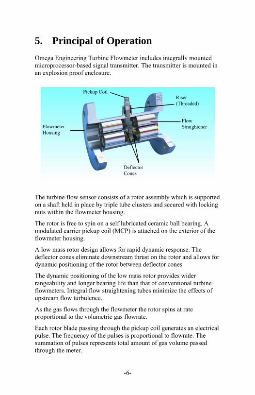
Omega Engineering Turbine Flowmeter includes integrally mounted microprocessor-based signal transmitter. The transmitter is mounted in an explosion proof enclosure.
The turbine flow sensor consists of a rotor assembly which is supported on a shaft held in place by triple tube clusters and secured with locking nuts within the flowmeter housing.
The rotor is free to spin on a self lubricated ceramic ball bearing. A modulated carrier pickup coil (MCP) is attached on the exterior of the flowmeter housing.
A low mass rotor design allows for rapid dynamic response. The deflector cones eliminate downstream thrust on the rotor and allows for dynamic positioning of the rotor between deflector cones.
The dynamic positioning of the low mass rotor provides wider rangeability and longer bearing life than that of conventional turbine flowmeters. Integral flow straightening tubes minimize the effects of upstream flow turbulence.
As the gas flows through the flowmeter the rotor spins at rate proportional to the volumetric gas flowrate.
Each rotor blade passing through the pickup coil generates an electrical pulse. The frequency of the pulses is proportional to flowrate. The summation of pulses represents total amount of gas volume passed through the meter.
Pickup Coil
Flowmeter Housing
Riser (Threaded)
Flow Straightener
Deflector Cones
-7-
The number of pulses generated per cubic foot is called the calibration factor or K-Factor. This calibration factor is programmed into the electronic transmitter to calculate correct flowrate.
The MCP pickup is a type of coil which eliminates pickup drag and requires a Modulated Carrier Signal Conditioner circuit. The MCP works on a principle where the motion of the rotor modulates a high frequency signal. The conditioner demodulates, filters, amplifies, and shapes the resulting signal prior to sending it to the microcontroller.
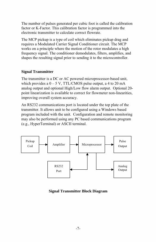
Signal Transmitter
The transmitter is a DC or AC powered microprocessor-based unit, which provides a 0 – 5 V, TTL/CMOS pulse output, a 4 to 20 mA analog output and optional High/Low flow alarm output. Optional 20-point linearization is available to correct for flowmeter non-linearities, improving overall system accuracy.
An RS232 communications port is located under the top plate of the transmitter. It allows unit to be configured using a Windows based program included with the unit. Configuration and remote monitoring may also be performed using any PC based communications program (e.g., HyperTerminal) or ASCII terminal.
Signal Transmitter Block Diagram
Pickup
Coil Amplifier Microprocessor Pulse
Output
Analog Output
RS232
Port
-8-
Material Selection and Construction
The housing is made of 316 stainless steel. The rotor is made of 17.4 pH stainless steel. Bearings are shielded, ceramic hybrid ball bearings and are made of 440C stainless steel. Bearings are self lubricating type and do not require any external lubrication.
Flowmeter Calibrations
The standard calibration provided with an Omega gas turbine flowmeter consists of a 10-point water calibration that is traceable to NIST. Based on this water calibration, we derive an average k-factor for water for the flowmeter. The average k-factor for water is then converted to ACF by using the following equation.
K-Factor / .134 = pulses/ACF
The uncertainty of this calibration methodology is +/-2%
The gas flowmeters are optionally available with actual gas calibrations at an additional charge. The uncertainty of an actual gas calibration is +/-0.5%. Actual gas calibrations are generally recommended for custody transfer (billing) applications.
The k-factor on turbine flowmeters used on gas service is NOT density dependent. The flowmeter “turndown” range is density dependent. The higher the operating density; the better the flow turndown range is on any Omega gas turbine flowmeter.
-9-
6. Installation
Inspect all packages for any indications of damage which may have occurred during shipment. Verify that all meter parts or auxiliary components have arrived with the shipment. Refer to the packing list/invoice for a detailed list of items included in the shipment. The flowmeter should be installed horizontally for proper operation. It is required to install meter with a minimum straight run of pipe approximately 10 pipe diameters ahead of the inlet and 5 pipe diameters following the outlet. The meter housing is marked by a flow direction arrow and the inlet is marked ‘IN’ and the outlet is marked ‘OUT’. The meter must be installed in the piping in the correct orientation to ensure the most accurate and reliable operation. Install meter with adequate distance and isolation from electric motors, transformers, welding equipment and solenoids to avoid any electromagnetic interference from ambient electrical field.

-10-
A typical flowmeter installation is shown below:
Figure 1: Typical Flowmeter Installation
Blocking and Bypass valves should be installed if it is necessary to do preventive maintenance on the flowmeter without shutting down the flow system. The Bypass valve can be opened before the Blocking valves allowing the flow to continue while removing the turbine flowmeter for service.
IMPORTANT: All flow lines should be purged prior to installing the meter. To prevent possible damage to the meter, install the meter ONLY in flow lines that are clean and free of debris.
Upon initial start-up of the system a spool piece should be installed in place of the flowmeter so that purging of the system can be performed to remove all particle debris which could cause damage to the meter internals.
CAUTION: Avoid over-spinning the meter. Over-spinning the meter may cause damage to the meter internals and lead to needless meter failure.
BYPASS RUN
Turbine FlowmeterStrainer
Blocking ValveBlocking Valve
Flow Straighener
Bypass Valve
METER RUN

-11-
7. Transmitter Wiring
Shielded cables are recommended for all input and output signals. The shield should be connected to the earth ground lug on the transmitter. The shield on the opposite end of the cable should be left unconnected.
This wiring practice is required for electromagnetic compatibility, as per EMC-Directive 89/336/EEC of the Council of European Community. DC Power Supply (13-30 VDC)
AC Power Supply (100-240 VAC) AC power for TRANSMITTER requires an optional circuit board, PCA182. The Alarm option (PCA184) is not available when the AC Power option is equipped.
N/C
N/C
POWER
PULSE-
N/C
ANLGSUPPLY
SIG+DC SIG-
+ DC+
DC-
- PULSE+
DC-
DC+
SIG-
PULSE-
N/C
N/C
PULSE+
SIG+
ANLG
N/C
NEUTRAL HOT
L1
L2 PLUG AC MALE
-12-
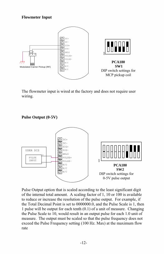
Flowmeter Input
The flowmeter input is wired at the factory and does not require user wiring. Pulse Output (0-5V) Pulse Output option that is scaled according to the least significant digit of the internal total amount. A scaling factor of 1, 10 or 100 is available to reduce or increase the resolution of the pulse output. For example, if the Total Decimal Point is set to 0000000.0, and the Pulse Scale is 1, then 1 pulse will be output for each tenth (0.1) of a unit of measure. Changing the Pulse Scale to 10, would result in an output pulse for each 1.0 unit of measure. The output must be scaled so that the pulse frequency does not exceed the Pulse Frequency setting (100 Hz. Max) at the maximum flow rate
1
PCA180 SW2
DIP switch settings for 0-5V pulse output
PCA180 SW1
DIP switch settings for MCP pickup coil
1 A B
Modulated Carrier Pickup (RF)
N/C
PULSE-
N/C
N/C
SIG+
ANLG
SIG-
DC+
DC-
PULSE+C
PULSE INPUT
-
+ USER DCS
N/C
PULSE-
N/CN/C
SIG+
ANLG
SIG-
DC+
DC-
PULSE+

-13-
AF
flowratemAxmAcurrent 164
Analog Output
N/C
POWER
PULSE-
N/C
N/C
SUPPLY
SIG+
ANLG
DC
SIG-
+
DC+
LOAD
DC-
- +
-
PULSE+
Analog Output is proportional to the flow rate. Default settings are 4mA (1V) at zero flow and 20mA (5V) at max flow rate of the turbine.
The following equations are used to compute the flow rate and analog output current. Where:
Kfactor = Is dependent on the Flow Calculation Method setting and
is either the Average K-Factor or the Linearized K-Factor from the Frequency / K-Factor table.
FM = Is the Flow rate Units setting of 0, 1, or 2. Where “0” is For Seconds, “1” is for Minutes, and “2” is for Hours. CF = Is the Correction Factor setting.
Where: AF = Is the 20 mA maximum Flow rate value.
xCFxKfactor
frequencyflowrate FM60
PCA183, SW1 4–20 mA Output
1
PCA183, SW1 1-5 V Output
1

-14-
If the calculated flowrate is greater than the AF setting, the current will be set to 24mA to indicate an “Over-range” condition.
The analog output response time to reach steady state due to a change in the flow rate is approximately 0.25 seconds. When flow stops, the time for the analog output to return to 4 mA will be between 3 and 12 seconds, depending on the Maximum Sample Time (MST) setting. MST is adjusted using the NB= (DATA) command, where NB is a value between 1 and 80. The default MST setting is NB= 1. Adjusting the MST is only recommended for low flow applications where the minimum input frequency is below 1 Hz.
Alarm Output
Optional High/Low Flow Alarm feature requires an optional circuit board, PCA184. The Alarm option is not available when the AC Power option is equipped.
Hi/Lo Alarm (Relay)
SIG+
SIG-
DC+
DC-
PULSE+
NC1
COM1
NO1
High/Low-Nomally Closed
High/Low-Nomally Open
High/Low-COM
N/C
N/C
N/C
PULSE-
ANLG
1
PCA184
SW1
DIP switch settings
for relay alarm

-15-
Hi/Lo Alarm (0-5V)
SIG+
COM
N/C
DC+
DC-
ANLG
PULSE-
PULSE+
SIG-
N/C
ALARM1
USER DCS
IndicatorAlarm
+
-
N/C
Hi/Lo Alarm (Open Collector)
USER DCS
AlarmIndicator
2.7K
V+
+
-
N/C
N/C
N/C
SIG+
ALARM1
DC-
SIG-
COM
ANLG
PULSE+
PULSE-
DC+
1
PCA184 SW1
DIP switch settings for 0-5V alarm
1
PCA184
SW1 DIP switch settings
for open collector alarm

-16-
RS232 Communications Port
The RS232 serial port connector is located under the top plate of transmitter and may be accessed by removing the two screws from the top plate. A matching connector is provided with Communications Cable supplied with transmitter. Transmitter unit has to be powered from external supply in order to be able to communicate. Additional power for TRANSMITTER communication circuitry is supplied by the RS232 serial port of the computer/terminal. COM port settings must be set as follows:
Baud Rate: 2400
Data Bits: 8
Parity: None
Stop bits: 1
Handshaking: None
Communications Cable
Tx 3
Rx 2
DTR 4
SIG COM 5
CD 1
6 DSR
7 RTS
8 CTS
9 NC
DB9
VDC1
VDC2
Pin 2
Pin 1
Molex0511100660 orEquivalent

-17-
Lock NutHanger/Flow Straightener
Cone Shaft BearingRotor
8. Maintenance and Troubleshooting
Pickup Coil Testing
Testing the MCP pickup coil requires measuring the resistance with an ohmmeter.
1. Measure the resistance between pin A and pin B. The resistance should be approximately 11.5 10% Ohms.
2. The resistance from any pin to the case should be greater than 1 mega Ohm.
If either resistance measurement fails, replace the pickup coil. When installing a coil, make sure to firmly seat the coil in the flowmeter housing.
Bearing Testing
It is recommended that the shielded, self lubricating ceramic ball bearings be checked periodically for wear. The cleanliness of the gas affects the life expectancy of the bearings.
It is recommended that the bearings be replaced if any signs of wear are apparent. An unexplained shift in the output accuracy could be a sign of worn bearings.
CAUTION: If bearings are allowed to operate without replacement at the recommended interval, the accuracy of the device may drift from the original calibration and if left long enough severe damage to the rotor and/or internals may occur.
The shielded, self lubricating 440c SS ball bearings may be changed in the field.
Figure 1 Exploded View - Flowmeter Internals
-18-
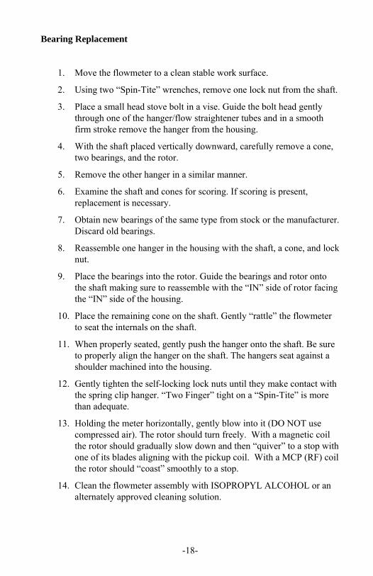
Bearing Replacement
1. Move the flowmeter to a clean stable work surface.
2. Using two “Spin-Tite” wrenches, remove one lock nut from the shaft.
3. Place a small head stove bolt in a vise. Guide the bolt head gently through one of the hanger/flow straightener tubes and in a smooth firm stroke remove the hanger from the housing.
4. With the shaft placed vertically downward, carefully remove a cone, two bearings, and the rotor.
5. Remove the other hanger in a similar manner.
6. Examine the shaft and cones for scoring. If scoring is present, replacement is necessary.
7. Obtain new bearings of the same type from stock or the manufacturer. Discard old bearings.
8. Reassemble one hanger in the housing with the shaft, a cone, and lock nut.
9. Place the bearings into the rotor. Guide the bearings and rotor onto the shaft making sure to reassemble with the “IN” side of rotor facing the “IN” side of the housing.
10. Place the remaining cone on the shaft. Gently “rattle” the flowmeter to seat the internals on the shaft.
11. When properly seated, gently push the hanger onto the shaft. Be sure to properly align the hanger on the shaft. The hangers seat against a shoulder machined into the housing.
12. Gently tighten the self-locking lock nuts until they make contact with the spring clip hanger. “Two Finger” tight on a “Spin-Tite” is more than adequate.
13. Holding the meter horizontally, gently blow into it (DO NOT use compressed air). The rotor should turn freely. With a magnetic coil the rotor should gradually slow down and then “quiver” to a stop with one of its blades aligning with the pickup coil. With a MCP (RF) coil the rotor should “coast” smoothly to a stop.
14. Clean the flowmeter assembly with ISOPROPYL ALCOHOL or an alternately approved cleaning solution.

-19-
9. Communication Protocols
Message Format and Timeout
Communication messages consist of a string of ASCII characters terminated by a carriage return character. The maximum message length coming to the unit is 20 characters, including the carriage return. The unit will transmit no more than 35 characters before transmitting a carriage return.
If a message longer than 20 characters sent, the instrument responds with
“Command Sequence is Too Long!<NL>”
If an unrecognized or invalid command is sent, the instrument responds with
“Invalid Command! <NL>”
The UNIT echoes all received messages and then transmits a response string terminated with a carriage return. If the sending unit takes longer than one minute to send a message, UNIT aborts the message by clearing the receive buffer.
If the sending unit (PC or other such device) wishes to change a setting on the UNIT, the sending unit shall follow the command with an equal sign (“=”) with the data following immediately after the equal sign. The carriage return terminates the message.
Any UNIT response that sends data back to the sending unit shall have an equal sign (“=”) followed by the data. Space is allowed between the equal sign and the data on the return message, but the total message length is limited to 35 characters.
READ Example:
To read the number of points that the UNIT has in the K factor table, send
“NP<CR>”
The UNIT echoes the sent message, and responds with
“NUM PTS=2<CR>”
WRITE Example:
To change the number of points to 20 in the K factor table, the sending unit shall send
“NP=20<CR>”
-20-
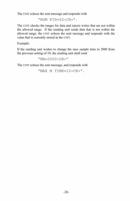
The UNIT echoes the sent message and responds with
“NUM PTS=20<CR>”.
The UNIT checks the ranges for data and rejects writes that are not within the allowed range. If the sending unit sends data that is not within the allowed range, the UNIT echoes the sent message and responds with the value that is currently stored in the UNIT.
Example:
If the sending unit wishes to change the max sample time to 2000 from the previous setting of 10, the sending unit shall send
“NB=2000<CR>”
The UNIT echoes the sent message, and responds with
“MAX M TIME=10<CR>”.
-21-
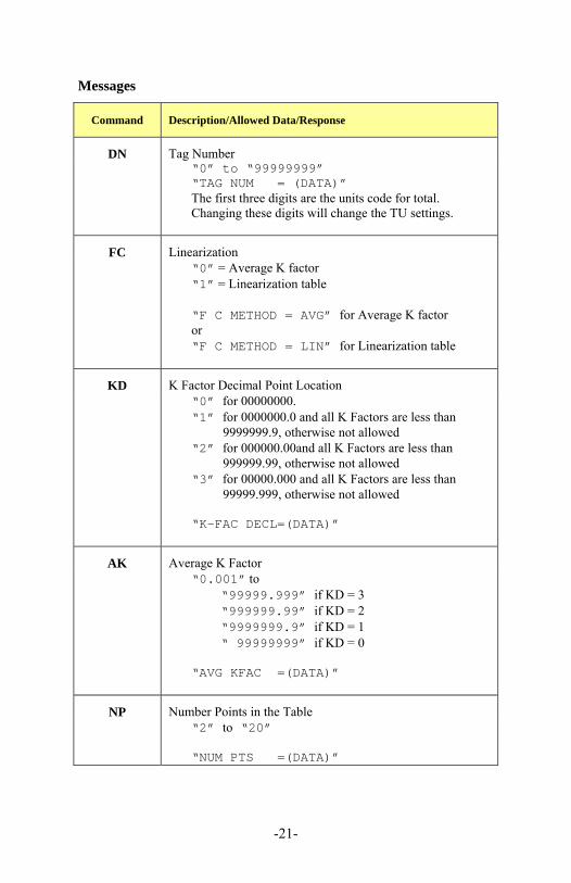
Messages
Command Description/Allowed Data/Response
DN Tag Number
“0” to “99999999” “TAG NUM = (DATA)” The first three digits are the units code for total. Changing these digits will change the TU settings.
FC Linearization
“0” = Average K factor “1” = Linearization table “F C METHOD = AVG” for Average K factor or “F C METHOD = LIN” for Linearization table
KD K Factor Decimal Point Location
“0” for 00000000. “1” for 0000000.0 and all K Factors are less than
9999999.9, otherwise not allowed “2” for 000000.00and all K Factors are less than
999999.99, otherwise not allowed “3” for 00000.000 and all K Factors are less than
99999.999, otherwise not allowed “K-FAC DECL=(DATA)”
AK Average K Factor
“0.001” to
“99999.999” if KD = 3 “999999.99” if KD = 2 “9999999.9” if KD = 1 “ 99999999” if KD = 0
“AVG KFAC =(DATA)”
NP Number Points in the Table
“2” to “20” “NUM PTS =(DATA)”
-22-
Command Description/Allowed Data/Response
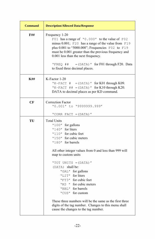
F## Frequency 1-20
F01 has a range of “0.000” to the value of F02 minus 0.001; F20 has a range of the value from F19 plus 0.001 to “5000.000”; Frequencies F02 to F19 must be 0.001 greater than the previous frequency and 0.001 less than the next frequency.
“FREQ ## =(DATA)” for F01 through F20. Data to fixed three decimal places.
K## K-Factor 1-20
“K-FACT # =(DATA)” for K01 through K09. “K-FACT ## =(DATA)” for K10 through K20. DATA to decimal places as per KD command.
CF Correction Factor
“0.001” to “9999999.999” “CORR FACT =(DATA)”
TU Total Units
“100” for gallons “140” for liters “110” for cubic feet “150” for cubic meters “180” for barrels All other integer values from 0 and less than 999 will map to custom units “TOT UNITS =(DATA)” (DATA) shall be:
“GAL” for gallons “LIT” for liters “FT3” for cubic feet “M3 ” for cubic meters “BBL” for barrels “CUS” for custom
These three numbers will be the same as the first three digits of the tag number. Changes to this menu shall cause the changes to the tag number.

-23-
Command Description/Allowed Data/Response
FM Rate Units
“0” for seconds “1” for minutes “2” for hours “3” for days “FLOW UNITS=(DATA)” (DATA) shall be:
“SEC” for seconds “MIN” for minutes “HR ” for hours “DAY” for days
NB Max Sample Time
“1” to “80” “MAX M TIME=(DATA)”
LF Out Low
“0.000” to a maximum value of the Out High setting “4mA FLOW =(DATA)”
AF Out High
Minimum is the Out Low Setting (LF) to a maximum of the following:
“99999.999” if RD = 3 “999999.99” if RD = 2 “9999999.9” if RD = 1 “ 99999999” if RD = 0
“20mA FLOW =(DATA)”

-24-
Command Description/Allowed Data/Response
PS Pulse Scale
“0” for OFF “1” for 1 “10” for 10 “100” for 100 “PULS SCALE=(DATA)” (DATA) shall be:
“OFF” for OFF “1” for 1 “10” for 10 “100” for 100
FO Pulse Frequency
“1” “2” “4” “8” “PULS FREQ =(DATA)”
UA Alarm Function
“0” for OFF “1” for RATE “2” for TOTAL “ALARM FUNC=(DATA)” (DATA) shall be:
“OFF” for OFF “RAT” for RATE “TOT” for TOTAL

-25-
Command Description/Allowed Data/Response
AL Alarm Out
“0.001” to a maximum defined as follows: If UA is RATE:
“99999.999” if RD = 3 “999999.99” if RD = 2 “9999999.9” if RD = 1 “ 99999999” if RD = 0
If UA is Total or Off:
“99999.999” if TD = 3 “999999.99” if TD = 2 “9999999.9” if TD = 1 “ 99999999” if TD = 0
“ALARM OUT =(DATA)”
OC Current Out
“0” - Current output follows rate. “1” - Current output set to 4mA. “2” - Current output set to 12mA. “3” - Current output set to 20mA. For “0”, response = “ Output equal to input.” For “1”, response = “ Output is 4mA.” For “2”, response = “ Output is 12mA.” For “3”, response = “ Output is 20mA.”
PR Pulse Output Controlled By PS and FO
“ Pulse Output Released ” The PS and FO menus shall control the pulse output. Used to terminate the TP command.
-26-
Command Description/Allowed Data/Response
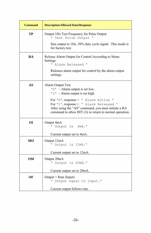
TP Output 1Hz Test Frequency for Pulse Output
“ Test Pulse Output ” Sets output to 1Hz, 50% duty cycle signal. This mode is for factory test.
RA Release Alarm Output for Control According to Menu Settings
“ Alarm Released ” Releases alarm output for control by the alarm output settings.
AS Alarm Output Test
“0” – Alarm output is set low. “1” - Alarm output is set high. For “0”, response = “ Alarm Active ” For “1”, response = “ Alarm Released ” After using the “AS” command, you must initiate a RA command to allow HIT-2A to return to normal operation.
OI Output 4mA
“ Output is 4mA.” Current output set to 4mA.
MO Output 12mA
“ Output is 12mA.” Current output set to 12mA.
OM Output 20mA
“ Output is 20mA.” Current output set to 20mA.
OF Output = Rate (Input)
“ Output equal to input.” Current output follows rate.

-27-
Command Description/Allowed Data/Response
AA Auto Data
“F (DATA) R (DATA) T (DATA)” The response, not the echo, is sent every two seconds until it receives another message from the master. The (DATA) following the F denotes the frequency of the pulses to a precision of three places past the decimal, the (DATA) following the R denotes the rate to a precision of three places past the decimal, and the (DATA) following the T denotes the total to a precision of three places past the decimal.
DA Dump All
All of the responses in previous table. The UNIT gives all responses except for the CL command.
UI Unit Identification
“UNIT MODEL= XX YY.ZZ” Model and software number for the unit. XX is the hardware revision number, YY.ZZ is the software revision where YY is the major software revision and ZZ is the minor software revision.
RR Read Rate
“FLOW = (DATA)” (DATA) = “0” to the following maximums:
“99999.999” if RD = 3 “999999.99” if RD = 2 “9999999.9” if RD = 1 “ 99999999” if RD = 0
-28-
Command Description/Allowed Data/Response
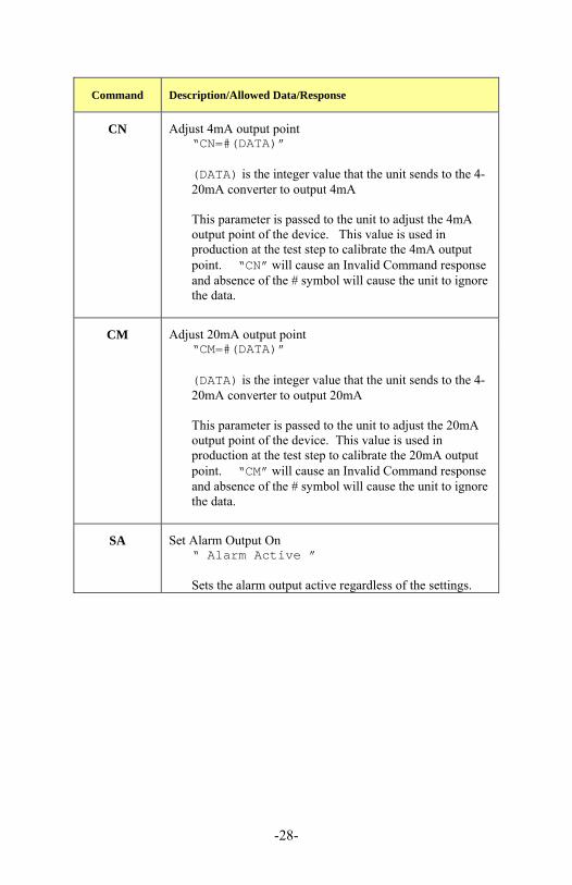
CN Adjust 4mA output point
“CN=#(DATA)”
(DATA) is the integer value that the unit sends to the 4-20mA converter to output 4mA This parameter is passed to the unit to adjust the 4mA output point of the device. This value is used in production at the test step to calibrate the 4mA output point. “CN” will cause an Invalid Command response and absence of the # symbol will cause the unit to ignore the data.
CM Adjust 20mA output point
“CM=#(DATA)” (DATA) is the integer value that the unit sends to the 4-20mA converter to output 20mA This parameter is passed to the unit to adjust the 20mA output point of the device. This value is used in production at the test step to calibrate the 20mA output point. “CM” will cause an Invalid Command response and absence of the # symbol will cause the unit to ignore the data.
SA Set Alarm Output On
“ Alarm Active ” Sets the alarm output active regardless of the settings.

-29-

-30-
M5116/0312