omni-directional hovercraft design as a foundation for mav
TRANSCRIPT

Omni-Directional Hovercraft Design as a Foundation forMAV Education
Carrick Detweiler, Brent Griffin, and Heath Roehr
Abstract— Quad-rotor Micro Aerial Vehicles (MAVs) areused widely in research and increasingly in commercial ap-plications as the cost of these platforms has dropped. The costof entry, however, is still high in large part due to the timeand effort involved in repairing vehicles after crashes whilelearning about the system design and dynamics. In this paper,we present an omni-directional hovercraft, which has dynamicssimilar to MAVs and can be used as an educational platformto teach students about the behavior and control of MAV-like platforms with minimal cost and effort. Teaching studentsabout the capabilities and challenges associated with MAVs iscritical for educating future engineers and scientists that willdevelop and use the next generation of MAVs. In addition,the hovercraft provides a safe platform for researchers to testcontrol and coordination algorithms before trying them onhigher-cost MAVs.
I. INTRODUCTION
Quad-rotor Micro Aerial Vehicles (MAVs) and UnmannedAerial Vehicles (UAVs) are being used widely in researchlabs and are finding an increasing number of commercialapplications as the cost of these platforms continues to drop.It is critical to educate students how to design and controlMAVs to advance future research and commercial adoption.Traditional robotics education with wheeled robots fails toaddress many of the fundamental challenges associated withMAVs. In particular, MAVs cannot simply stop to processdata and collect sensor information since their dynamicswill likely cause their position to drift. This requires aneducational focus on dynamics and real-time control andshould be taught on a MAV-like platform.
In our MAV-focused research lab1, we use a variety ofMAVs ranging from platforms provided by Ascending Tech-nologies [1] to Parrot AR.Drones [2] that cost approximately$5-10k and $300, respectively. At $300, the Parrot AR.Droneseems like an ideal, low-cost platform to teach and educateundergraduate students about using and developing MAVs.Our experience, however, is that the low-cost platforms havelimited payloads, closed-source firmware, and limited inputsfor additional sensors. In addition, while learning how tocontrol the MAVs, students tend to quickly and frequentlycrash these vehicles, greatly increasing the cost and effortinvolved in using MAVs with the classroom.
We are grateful to NSF IIS-1116221 and NSF CNS-1217400, the UNLCSE department, and a UNL Faculty Seed Grant for supporting parts ofthis work.
All authors are members of the Nebraska Intelligent MoBileUnmanned Systems (NIMBUS) Lab, Computer Science andEngineering, University of Nebraska–Lincoln, Lincoln, NE 68588,USA. [email protected], [email protected] [email protected]
1Nebraska Intelligent MoBile Unmanned Systems (NIMBUS) Lab
Fig. 1. MAVs and hovercraft in the NIMBUS Lab.
We have designed an omni-directional hovercraft, shownin Fig. 1, that has control architecture and dynamics similarto most quad-rotor MAVs. We have used this platformin the classroom to teach students about the fundamentalchallenges associated with developing and controlling MAV-like platforms in two courses: Embedded Systems (CSCE436/836) and Robotics (CSCE 496/896). In addition, we usethis platform in our research lab to prototype algorithmsbefore moving them onto MAVs.
The hovercraft has a flexible design with typical diam-eters ranging from 12 to 18 inches. It is constructed frominexpensive and easily available materials. This encouragesexploration of the design space and various configurations,since it is easy and inexpensive to try a different arrangement.For our classes and research we configure the thrustersto enable control of all degrees of freedom in the twodimensional plane. This makes the control and dynamics ofthe hovercraft very similar to a MAV.
The rest of this paper details the similarities and differ-ences between MAVs and our omni-directional hovercraft.In Section III, we explore the dynamics of both vehiclesand note that they are inertia-driven, which makes themsignificantly different from traditional wheel-based groundrobots. In Section IV, we examine the low and high-levelarchitecture of the hovercraft. At a low-level, we use customdesigned circuit boards to control the system. At a high-level,we use Robot Operating System (ROS) [3] for control of thehovercraft, which makes it easy to substitute a hovercraftfor a MAV when testing various algorithms. In Section V,we discuss our implementation and experiences using thehovercraft for a variety of tasks in the classroom. Finally, weconclude in Section VI by discussing limitations and futurework. But first, we begin with the related work in Section II.

Robot CostUSC robomote $150iRobot Create $220
Rice r-one $220UNL Hovercraft $225-$275
LEGO Mindstorms $250CEENBoT $300
Parrot AR.Drone MAV $300HandyBoard $350EPFL e-puck $979
TABLE ICOST OF SELECTED EDUCATIONAL ROBOTS, SOME DATA FROM [4], [5].
II. RELATED WORK
With the advent of smaller and less expensive roboticplatforms, purchasing robots such as the Roomba for educa-tional purposes has become a viable way to teach studentsabout advanced robotic principles without the need for largerobotic laboratories [6], [7], [5]. Because small, yet capablerobots can be purchased within the budget of a typical course,more educators can take advantage of unique opportunities tohelp students learn robotics with hands-on experiences. Thismakes it possible for students to learn about the challengesassociated with the uncertainty in sensing and control onreal robots. Table I summarizes the cost of a small subsetof robots that are used in education, including the hovercraftdeveloped in this paper.
In addition to ground-based robots, education and researchon the control and applications of robotic quad-rotor MAVshas been rapidly expanding in recent years [8], [9], [10].While the physical design and flight dynamics of quad-rotorMAVs is greatly simplified when compared to a fixed-wingaircraft or helicopter, the algorithms and heuristics used tocontrol MAVs are quite complex [8].
The cost associated with purchasing and repairing MAVs(after inevitable crashes) has largely kept MAVs out of theclassroom, except under highly supervised conditions thatmay prevent students from learning by experiencing mis-takes. Quad-rotor MAVs are different from most traditionalground robots because they are omni-directional and largelyinertia-driven. Ground based omni-directional robots havebeen designed and optimized for a variety of tasks [11], [12]and have also been used in education. However, MAVs differfrom these platforms because their inertia is large comparedto their input forces and they do not have friction basedwheels (or wings in the case of an airplane) that can beused to turn the vehicle. In this paper, we develop an omni-directional, inertia-driven hovercraft robot that operates nearthe ground with characteristics similar to most quad-rotorMAVs. This inexpensive platform enables MAV research andeducation with a significantly lower operational cost.
In addition to hardware, software advancements with ROShave enabled rapid and reliable software engineering forrobotic systems, both for educators and researchers [13].ROS offers students a way to learn about fault-tolerantand scalable software engineering in the context of roboticengineering. We use ROS to enable modularity and theability to use the same interfaces for both our hovercraftand MAVs (which have existing ROS interfaces).
III. SIMILARITIES IN DYNAMICS
The key characteristic that distinguishes omni-directionalhovercrafts and MAVs from traditional ground-based omni-directional vehicles is that they have small input forcescompared to their inertia. The speed and direction of anomni-directional wheeled vehicle can be directly controlledand adjusted by turning its wheels [14], [15], which requireslittle energy. Hovercrafts and MAVs, however, are subject toa much higher ratio of inertia to resistance. In order to shiftdirections, the current momentum must be countered with asignificant new input force. If active control is not applied,it will continue to drift and/or rotate.
Hovercrafts have the same number of degrees of freedom(DOF) as MAVs when they are performing tasks independentof elevation (e.g. navigating an unknown building [16]).There is less of a connection between MAVs and hovercraftswhen the MAVs are performing aggressive maneuvers [17],[18] due to the large tilt angles and changes in elevation. Inthis paper, we analyze MAV and hovercraft similarities undersituations where speeds are low and maneuvers are smooth.We now present an overview and comparison of the inertialdynamics for MAVs and hovercrafts.
A. MAV Dynamics
Translational movement in MAVs is performed throughthe use of pitch and roll. Tilting the MAV will introducea horizontal thrust component that will allow the MAV totranslate (Translate Left, Fig. 2). In addition, the overallthrust must be increased to maintain the MAVs currentelevation. Because pitch and roll are about perpendicularaxes, using them in conjunction allows translation in anydirection. A simple control scheme is to have the MAV’sbaseline thrust level adjust to control elevation, and thenperform small deviations on opposite rotors to control pitchand roll. The equations for MAV translational movement areas follows:
mmah = sinθ∑
Ft − Fd
mmaz = cosθ∑
Ft −mmg (1)
where mm is the mass of the MAV,ah is the horizontal acceleration,θ is the angle of tilt,Ft is the force of each rotor,Fd is the counter force from aerodynamic drag,and az is the vertical acceleration.It is important to note that with the assumption of con-
stant elevation, translation becomes a function of tilt. Oncehorizontal acceleration has begun, the only real limitationson speed are maintaining elevation with enough componentof
∑Ft, and drag which increases non-linearly with speed.
A MAV rotates by using the drag the rotor blades expe-rience opposite to their direction of rotation, which createsa torque on the vehicle. Since a quad-rotor MAV has twopairs of rotors turning clockwise and counterclockwise, anoverall moment is generated by strategically increasing anddecreasing the speed of the rotors, in turn altering the dragexperienced by each pair. Since the drag of each rotor is

Fig. 2. Schematic of the MAV forces to achieve rotation and translation.
proportional to the square of its rotational velocity [19], acontrolled unbalance can be introduced to rotate the MAV.Fig. 2 shows that speeding up rotors with clockwise drag andslowing down those with counterclockwise drag causes theMAV to rotate clockwise. This does not induce additionalpitch or roll since the pairs are opposite one another and thecomponent of thrust remains balanced across the center ofthe MAV. The rotational dynamics are:
Imα =∑
Mt −Md (2)
where Im is the rotational inertia of the MAV,α is the angular acceleration,Mt is the drag moment of each rotor,and Md is the counter moment from aerodynamic drag.
B. Hovercraft Dynamics and Comparison
Translational movement of hovercrafts along the groundplane is controlled by the one directional force output ofeach thruster. Ideally, coordinated thrusters pointing in atleast three directions allow omni-directional acceleration anddeceleration (Fig. 3) in the same fashion as tilt does forMAVs flying with small tilt angles (Eqn. 1). The equationfor hovercraft translational dynamics is:
mha =∑
Ft − Fd (3)
where mh is the mass of the hovercraft,a is the acceleration,Ft is the force of each thruster,and Fd is the counter force from skirt drag.Hovercraft speed, just as with MAVs, is limited by drag
and will reach a maximum when the force of drag is equalto the thruster force input to the system. The drag on thehovercraft is primarily due to limited contact between theinflated skirt and the ground. It is important to note thatpure translation (i.e. translation without rotation) when usinga single thruster can only occur if the thruster is alignedwith the hovercraft’s center of mass. If a thruster has aperpendicular offset from the hovercraft’s center of mass withrespect to the direction of its input force, it will introducea moment about the center of mass (Fig. 3). Each moment
Fig. 3. Schematic of the hovercraft thruster layouts and forces to achieverotation and translation.
is equal to the cross product of distance from the center ofmass of the hovercraft to the thruster and thruster force. Toperform rotation without translation, rotational thrusters mustbe countered with an equal magnitude of opposing thrustinput, but by translational thrusters aligned with the center ofmass. Just as rotation results from generated rotor momentson a MAV (Eqn. 2), rotation on the hovercraft is given bythe following equation:
Ihα =∑
Ft × r −Md (4)
where Ih is the rotational inertia of the hovercraft,α is the angular acceleration,Ft is the force of each thruster,r is the distance to each thruster from the center of mass,and Md is the counter moment from skirt drag.Careful planning of thruster placement and control im-
plementation allows a hovercraft to rotate and translate inany direction, in varying magnitude, in the same fashion asa MAV. Thrusters add momentum to the system, and thismomentum is typically higher than the drag. This means thatsufficient planning must be made in advance to coordinate achange in direction or to stop.
The payload capacity of the hovercraft is proportionalto the thrust generated by the downward-facing thruster,the hovercraft diameter, efficiency, and the diameter of thedownward-facing thruster:
P =FtDhη
At(5)
where P is the payload of the hovercraft,Ft is the force produced by the downward-facing thruster,Dh is the diameter of the hovercraft,η is the efficiency,and At is the area of the downward-facing thruster.
Efficiency accounts for the air that escapes underneath theskirt of the hovercraft. It varies depending on the uniformityof the skirt and the smoothness of the ground surface.Efficiency can be determined experimentally for differentconfigurations.

Fig. 4. Picture of the hoverboard that provides low-level control.
A final principal attribute shared between hovercrafts andMAVs is the importance of balanced and controlled correc-tions. Because control is based on the force input of placedthrusters or rotors, changes to either vehicle that unbalancethe center of mass or rotational inertia can dramaticallychange the handling of the vehicle. If too many componentsare placed on one side of the hovercraft, for example, theshift in the center of mass will cause previously alignedtranslational thrusters to generate moments and rotationswhen not intended. Best results are obtained by mechanicallybalancing the system and then using feedback control tomaintain constant heading to correct for unwanted rotationfrom unaligned thrusters or uneven drag. The similarities indynamics between hovercrafts and MAVs show that omni-directional hovercrafts can be used to learn about the funda-mentals of control and component placement that are directlyapplicable to MAVs.
IV. SIMILARITIES IN ARCHITECTURE
We designed the control architecture of the hovercraftsimilar to that of most MAVs. At a low-level there is a pair ofmicrocontrollers that perform motor control, interface withsensors, and provide an abstracted interface for the higher-level system. The high-level control is implemented in ROS,with an interface that is compatible with existing ROS MAVcontrol nodes. In this section, we detail both the low andhigh-level control systems and architectures.
A. Low-Level Architecture
The hoverboard was designed to easily interface with awide variety of sensors and to provide base onboard sensorsthat are similar to those found on most MAVs. At the low-level the hovercraft is controlled by the hoverboard, shownin Fig. 4. The hoverboard has a pair of ATmega1284Pprocessors, with one operating at 8MHz at 3.3V and theother at 20MHz at 5.0V. The two processors are connectedover an I2C bus that is also exposed externally to enableeasy expansion. Nearly all MAVs are controlled by multipleprocessors, so when designing the hoverboard, we decidedto put two lower-end processors instead of a single morecapable processor. This gives students in embedded systems-type courses the opportunity to learn how to implementprotocols to communicate between the processors and theyare also able to learn how to balance tasks between theprocessors to ensure real-time operation.
The hoverboard has a magnetometer and a one-axis gyro-scope. These are used to control the rotation of the hover-craft and to teach students about data fusion on embeddedsystems. These are the same sensors found on most MAVs,minus the accelerometer, which is not needed since thehovercraft always stays level relative to the ground.
The hoverboard also has current feedback sensors, analogsensor inputs, digital I/O pins, serial, SPI ports, and PWMoutputs. Since the hoverboard has both 5V and 3.3V inputsand outputs, it is possible to interface with nearly any typeof sensor or actuator. We have added range finders, linedetectors, bump sensors, accelerometers, servos, computermice sensors, and a number of other devices. The ability toexpand makes it easy to do a wide variety of course projects.
For wireless external control the 5V processor has aZigbee radio. The 3.3V processor drives the hoverboardthrusters using a PWM signal to control MOSEFTs, whichenables variable speed, uni-directional control of the thrusters(they can push, but not pull). The hovercraft is typicallypowered by a 7.4V two cell LiPo battery that is monitored byon-board circuitry to disable operation if the voltage dropstoo low. The system is protected from over current or shortcircuits with an 8A replaceable fuse.
The hovercraft was used as the core platform for anembedded systems course. In the course the students learnedto configure and control most of the peripherals on the hover-board and implemented data fusion algorithms, proportional-integral-derivative (PID) rotation controllers, communicationprotocols, and task schedulers. The design of the hoverboardis available online, but much of the functionality could alsobe replicated using a pair of Arduinos along with motorcontrol shields.
B. High-Level Control in ROS
Robotic Operating System (ROS) is a meta-operating sys-tem framework that enables distributed control of a roboticsystem. In addition, ROS greatly simplifies the inherentcomplexity of engineering software for robotic systems. Thearchitecture of ROS is based on a collection of computationalunits (referred to as nodes) that communicate with oneanother via a set of distinct publishers and subscribers(collectively referred to as topics). The nodes are highlycohesive and loosely coupled, making a system built withROS evolvable, fault-tolerant, and scalable. Further, ROSnodes in the same system are capable of running on differentcomputers (or robots), enabling off-line control and realtime communication. Because ROS nodes can be written ineither python or C++, object-oriented programming can beleveraged to increase modularity and encapsulation.
ROS is widely used by MAV researchers and there areopen-source implementations for controlling both the MAVsused in our research (Parrot AR.Drone and Ascending Tech-nologies Hummingbird). This, along with node modularity,makes ROS an ideal choice for our MAV-hovercraft, cross-compatible implementation. As shown in Fig. 5, we logicallyseparate the ROS nodes in our system into four categories:

Zigbee Interface
Joystick Interface
Camera Interface
Joystick Wrapper
Landmark Detector
Hoverboard Wrapper
Thruster Mapper
PID Controller
Movement Wrapper
Low-Level Interface
Low-Level Processing
Mid-Level Processing
High-Level Processing
Landmark Mapper
Motion Planner
Fig. 5. ROS control architecture. Dashed nodes are easily replaced withMAV-specific nodes, enabling algorithm prototyping on hovercraft.
(1) low-level interface, (2) low-level processing, (3) mid-level processing, and (4) high-level processing.
The nodes in the low-level interface are responsible forlow level communication and interfacing with devices suchas radios and sensors. These nodes subscribe to (i.e. con-sume) topics that contain low level data that is directlyreceived from or destined for sensors, thrusters, rotors,etc. They are responsible for converting low level data toand from serial message formats. In the event the data isoutbound (from other ROS nodes) these nodes instruct theoperating system to send them via the appropriate outputdevice. Inbound data (from sensors or radios) is appropriatelyconverted and published (i.e. emitted) to other ROS nodes.
The primary responsibility of low-level nodes is theabstraction to or from low level commands. These nodessubscribe to topics that are published from the low-levelinterface nodes, abstract the data in some way, and thenpublish the abstracted data to other ROS nodes. They alsosubscribe to topics that send abstracted data from higher levelnodes that must be converted into low-level commands thatare then published to the low-level interface nodes.
The mid-level processing nodes are central to the system.They often subscribe to and publish many topics. They areequipped to process both lower level data and higher leveldata (in terms of abstraction). In essence, they perform therequired system functions that bridge the gap between thelow-level nodes and high-level nodes.
High-level processing nodes generally interact with themost abstracted and processed data. In addition, they typi-cally implement the most sophisticated and complex featuresof the system. Because many fine-grain and platform-specificdetails are abstracted away at this level, the developer is freeto implement complex algorithms without having to managelarge amounts of system implementation complexity.
ROS Example Implementation:Fig. 5 presents an example system that uses a camera
to identify landmarks (in this case, barcodes), map theirlocations, and then plan motions within the map based on thelocation of the landmarks. In addition, the system providessupport for a manual override (i.e. the user can use a joystickto introduce movement commands at any time).
In this example, there are three low-level interface nodes:an interface for a Zigbee radio, joystick, and camera. Thesenodes enable communication with their respective devicesand bridge the gap between the operating system and ROS.
Each low-level interface node publishes and subscribesto a low-level processing node2. For example, messagesreceived from the joystick (via a low-level interface node)may have a high-precision data value for each button orjoystick on the device in the form of a multi-dimensionalarray. However, other higher-level ROS nodes may requirethat this be abstracted into a simple integer-valued format.A low-level processing node would handle this abstraction.
At the mid-level, a PID controller is shown that is re-sponsible for maintaining the desired heading and reducingundesired translational drift, as well as subscribing to andpublishing movement commands when they are required(acting as a movement command proxy of sorts).
In our example, there are two high-level processing nodes.The landmark mapping node maintains a map of the knownenvironment that the motion planner node can use to deter-mine which movement commands are required. The motionplanner node does not have to administer or control drift,platform-specific message formats, or deal with image dataformats. All of this processing is handled in lower levelsand only relevant, concise information is published to thehigh-level processing nodes.
ROS Modularity:The majority of this system could also be used directly
by a MAV with little modification (assuming the MAV isoperating in a two dimensional plane). The four dashed nodesin Fig. 5 are the only nodes that would need to be modifiedif a MAV were used in lieu of our hovercraft.
The modifications that are required to adapt this system fora MAV are low-level and platform specific. For example, theZigbee interface node must be modified to compute messagesin a format the MAV can understand. Similarly, the thrustermapper node must be replaced by a rotor mapper node(assuming the MAV requires individual rotor commands).The PID controller node may only require that its controlgain parameters be adjusted. In any case, replacing nodes ormodifying node parameters is as simple as editing an XMLfile that is used to launch the ROS nodes.
In the lab setting, a researcher can develop and test acomplex algorithm using our hovercraft implementation, andthen run the same algorithm using a MAV. If modificationsneed to be made after switching to a MAV (or from a MAVback to the hovercraft), they can be made to the high-levelprocessing nodes with little to no change required in themid-level processing nodes.
For educational use, individual courses can focus onparticular layers or touch on nodes at all levels. Classesfocused on hardware, sensors, or other device interfaces mayfocus on developing low-level nodes. Courses on control-
2In our example there exists a one-to-one relationship between low-levelinterface nodes and low-level processing nodes, however this is not requiredand may not be the case in other examples.

Fig. 6. PID controller step response to changing angles.
theory may focus on the mid-level control processing tasks,while courses on artificial intelligence may work on high-level nodes. A more general topics robotics course mayaddress nodes at all levels.
V. IMPLEMENTATION AND EXPERIENCES
In this section, we provide additional details on the hover-craft implementation. We also discuss our experiences withthe hovercraft when teaching two courses: Embedded Sys-tems (CSCE 436/836) and Robotics (CSCE 496/896). Bothof these courses had upper-level undergraduates as well asgraduate students. The Embedded Systems course had mostlyComputer Science and Computer Engineering students, whilethe Robotics course also had students from MechanicalEngineering, Electrical Engineering, and Physics.
A. Hovercraft Implementation Details
The hovercrafts are constructed from inexpensive materialsthat are available at local and online hardware and hobbyshops. The base is made of 1.5 inch rigid foam insulationand the skirt, which directs air to provide lift, is cut from a5 mil plastic sheet. Thrust is provided by up to 6 standardRC ducted fans. Control and processing is enabled by acustom-designed circuit board detailed in Section IV-A. Thetotal cost of the platform is $275 for small build quantitiesand drops to $225 for medium sized builds. This comparesfavorably to other educational robotics platforms as shownin Table I. The driving costs are the control board ($150 forsmall quantities), motors ($60 total), and battery ($40). Thebody components cost less than $25.
The low cost of the hovercraft’s body components encour-ages exploration of different configurations and layouts. Inthe courses using this platform, students have built circularbases with diameters ranging from 12 to 18 inches andsome groups experimented with different shapes for thebase, although all groups ended up preferring the circularbases that had better lift characteristics in practice. Thereare multiple tradeoffs to consider when choosing the basesize. Larger bases tend to allow for larger payloads and areless sensitive to weight imbalances. Having a large base andpayload, however, decreases the rate at which the hovercraftcan accelerate.
Compared to MAVs, the hovercrafts are very easy andquick to build and modify. In addition, the hovercrafts havesignificant payload capabilities that make it easy to mountnew hardware and sensors. The hovercrafts can hover with a
Fig. 7. Ball detected (left) based on the HSV image (right). Also seen isa scale-invariant landmark that can be identified for localization.
payload of over 2.5 kg (e.g. a netbook computer), but withthis much additional mass it accelerates very slowly. In typ-ical course projects, students have added range finders, linedetectors, bump sensors, accelerometers, servos, computermouse sensors, cameras, and a number of other devices.Fig. 8 shows a picture of the hovercraft configured with aball collection mechanism and camera, which was part ofthe final project competition and is detailed in Section V-C.
B. Feedback Control
One of the early projects for both courses was the im-plementation of a PID controller to enable precise headingcontrol of the hovercraft based on feedback from the gyro-scope and magnetometer. This uses the base hardware on thehoverboard and can be implemented either on the microcon-trollers or at a higher level in ROS. Actively controlling theangle is important even when trying to do pure translationsas small misalignments in the translational thrusters will addtorques that quickly add up to large rotational velocitiesif uncorrected. This is similar to quad-rotor MAVs, wherecontrol of each degree of freedom will impact the otherdegrees of freedom.
Fig. 6 shows the impulse response of a PD controller whenchanging the target angle. In practice no integral componentwas needed since the hovercraft has low friction and noexternal rotational forces. Note that there is a large initialovershoot, which is due to the rotational inertia associatedwith the hovercraft and is difficult to avoid with a PDcontroller without significantly slowing the response rate. Inpractice, we found that this level of overshoot is acceptablefor most applications which require smooth changes in angleand not stepwise changes. The overshoot can be reduced byadding a feed-forward component to the controller.
C. Ball Detection, Following, and Capture
The final project for the Robotics (CSCE 496/896) courseinvolved collecting as many balls at known locations aspossible in an environment augmented with scale-invariantvisual landmarks [20]. This combined techniques learnedin prior assignments including visual localization and nav-igation, ball detecting (see Fig. 7), and visual servoing. Inaddition, this project required augmenting the hovercraft witha gripper or ball collection mechanism, see Fig. 8.
These tasks required vision processing, which was initiallyperformed using a small Gumstix processor onboard thehovercraft. Unfortunately, the operational area had poor WiFibandwidth so ultimately students used wired webcams. Since
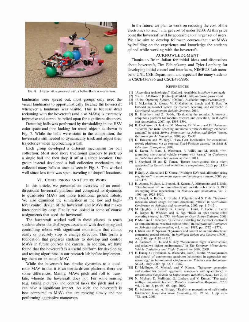
Fig. 8. Hovercraft augmented with a ball-collection mechanism.
landmarks were spread out, most groups only used thevisual landmarks to opportunistically localize the hovercraftwhenever a landmark was visible. This is because deadreckoning with the hovercraft (and also MAVs) is extremelyimprecise and cannot be relied upon for significant distances.
Detecting balls was performed by thresholding in the HSVcolor-space and then looking for round objects as shown inFig. 7. While the balls were static in the competition, thehovercrafts still needed to dynamically track and adjust theirtrajectories when approaching a ball.
Each group developed a different mechanism for ballcollection. Most used more traditional graspers to pick upa single ball and then drop it off at a target location. Onegroup instead developed a ball collection mechanism thatcollected many balls at once as seen in Fig. 8. This workedwell since less time was spent traveling to dropoff locations.
VI. CONCLUSIONS AND FUTURE WORK
In this article, we presented an overview of an omni-directional hovercraft platform and compared its dynamicsto quad-rotor MAVs and more traditional ground robots.We also examined the similarities in the low and high-level control design of the hovercraft and MAVs that makesinteroperability easy. Finally, we looked at some of courseassignments that used the hovercraft.
The hovercraft worked well in these classes to teachstudents about the challenges associated with developing andcontrolling robots with significant momentum that cannoteasily or precisely stop or change direction. This forms afoundation that prepares students to develop and controlMAVs in future courses and careers. In addition, we havefound that the hovercraft is a useful platform for developingand testing algorithms in our research lab before implement-ing them on an actual MAV.
While the hovercraft has similar dynamics to a quad-rotor MAV in that it is an inertia-driven platform, there aresome differences. Mainly, MAVs pitch and roll to trans-late, whereas the hovercraft does not. For some sensing(e.g. taking pictures) and control tasks the pitch and rollcan have a significant impact. As such, the hovercraft isbest compared to MAVs that are moving slowly and notperforming aggressive maneuvers.
In the future, we plan to work on reducing the cost of theelectronics to reach a target cost of under $200. At this pricepoint the hovercraft will be accessible to a larger set of users.We also aim to develop followup courses that use MAVsby building on the experience and knowledge the studentsgained while working with the hovercraft.
ACKNOWLEDGMENTThanks to Brian Julian for initial ideas and discussions
about hovercraft, Tim Echtenkamp and Tyler Lemburg fordeveloping initial control and interfaces, NIMBUS Lab mem-bers, UNL CSE Department, and especiall the many studentsin CSCE436/836 and CSCE496/896.
REFERENCES
[1] “Ascending technologies.” [Online]. Available: http://www.asctec.de[2] “Parrot AR.Drone.” [Online]. Available: http://ardrone.parrot.com/[3] “Robot Operating System.” [Online]. Available: http://www.ros.org/[4] J. McLurkin, S. Rixner, M. O’Malley, A. Lynch, and T. Barr, “A
low-cost multi-robot system for research, teaching, and outreach,” inDistributed Autonomous Robotic Systems, 2010.
[5] B. Tribelhorn and Z. Dodds, “Evaluating the roomba: A low-cost,ubiquitous platform for robotics research and education,” in Roboticsand Automation, 2007, pp. 1393–1399.
[6] B. Dickinson, O. Jenkins, M. Moseley, D. Bloom, and D. Hartmann,“Roomba pac-man: Teaching autonomous robotics through embodiedgaming,” in AAAI Spring Symposium on Robots and Robot Venues:Resources for AI Education, 2007, pp. 35–39.
[7] D. Housten and W. Regli, “Low-Cost localization for educationalrobotic platforms via an external Fixed-Position camera,” in AAAI AIEducation Colloquium, 2008.
[8] K. Dantu, B. Kate, J. Waterman, P. Bailis, and M. Welsh, “Pro-gramming micro-aerial vehicle swarms with karma,” in Conferenceon Embedded Networked Sensor Systems, 2011.
[9] J. Shepherd III and K. Tumer, “Robust neuro-control for a microquadrotor,” in Genetic and evolutionary computation, 2010, pp. 1131–1138.
[10] P. Sujit, A. Sinha, and D. Ghose, “Multiple UAV task allocation usingnegotiation,” in autonomous agents and multiagent systems, 2006, pp.471–478.
[11] H. Asama, M. Sato, L. Bogoni, H. Kaetsu, A. Mitsumoto, and I. Endo,“Development of an omni-directional mobile robot with 3 DOFdecoupling drive mechanism,” in Robotics and Automation, vol. 2,1995, pp. 1925–1930.
[12] O. Diegel, A. Badve, G. Bright, J. Potgieter, and S. Tlale, “Improvedmecanum wheel design for omni-directional robots,” in AustralasianConference on Robotics and Automation, 2002, pp. 117–121.
[13] M. Quigley, B. Gerkey, K. Conley, J. Faust, T. Foote, J. Leibs,E. Berger, R. Wheeler, and A. Ng, “ROS: an open-source robotoperating system,” in ICRA Workshop on Open Source Software, 2009.
[14] P. Muir and C. Neuman, “Kinematic modeling for feedback control ofan omnidirectional wheeled mobile robot,” in International Conferenceon Robotics and Automation, vol. 4, mar 1987, pp. 1772 – 1778.
[15] I. Khan and M. Spenko, “Dynamics and control of an omnidirectionalunmanned ground vehicle,” in Intelligent Robots and Systems (IROS),oct. 2009, pp. 4110 –4115.
[16] A. Bachrach, R. He, and N. Roy, “Autonomous flight in unstructuredand unknown indoor environments,” in The European Micro AerialVehicle Conference and Flight Competition 2009, 2009.
[17] H. Huang, G. Hoffmann, S. Waslander, and C. Tomlin, “Aerodynamicsand control of autonomous quadrotor helicopters in aggressive ma-neuvering,” in International Conference on Robotics and Automation(ICRA), may 2009, pp. 3277 –3282.
[18] D. Mellinger, N. Michael, and V. Kumar, “Trajectory generationand control for precise aggressive maneuvers with quadrotors,” inInternational Symposium on Experimental Robotics (ISER), Dec 2010.
[19] N. Michael, D. Mellinger, Q. Lindsey, and V. Kumar, “The graspmultiple micro-uav testbed,” Robotics Automation Magazine, IEEE,vol. 17, no. 3, pp. 56 –65, sept. 2010.
[20] D. Scharstein and A. Briggs, “Real-time recognition of self-similarlandmarks,” Image and Vision Computing, vol. 19, no. 11, pp. 763–772, sept. 2001.