omniswitch 6800 series advanced routing configuration...
TRANSCRIPT

Part No. 060199-10, Rev. ANovember 2004
OmniSwitch 6800 SeriesAdvanced Routing
Configuration Guide
www.alcatel.com

This user guide documents release 5.3.1 of the OmniSwitch 6800 Series.The functionality described in this guide is subject to change without notice.
Copyright © 2004 by Alcatel Internetworking, Inc. All rights reserved. This document may not be repro-duced in whole or in part without the express written permission of Alcatel Internetworking, Inc.
Alcatel® and the Alcatel logo are registered trademarks of Alcatel. Xylan®, OmniSwitch®, OmniStack®, and Alcatel OmniVista® are registered trademarks of Alcatel Internetworking, Inc.
OmniAccess™, Omni Switch/Router™, PolicyView™, RouterView™, SwitchManager™, VoiceView™, WebView™, X-Cell™, X-Vision™, and the Xylan logo are trademarks of Alcatel Internetworking, Inc.
This OmniSwitch product contains components which may be covered by one or more of the following U.S. Patents:
• U.S. Patent No. 6,339,830 • U.S. Patent No. 6,070,243 • U.S. Patent No. 6,061,368 • U.S. Patent No. 5,394,402• U.S. Patent No. 6,047,024• U.S. Patent No. 6,314,106• U.S. Patent No. 6,542,507
26801 West Agoura RoadCalabasas, CA 91301
(818) 880-3500 FAX (818) [email protected]
US Customer Support—(800) 995-2696International Customer Support—(818) 878-4507
Internet—http://eservice.ind.alcatel.com
ii OmniSwitch 6800 Series Advanced Routing Configuration Guide November 2004

Contents
About This Guide ......................................................................................................... vii
Supported Platforms ......................................................................................................... vii
Who Should Read this Manual? ......................................................................................viii
When Should I Read this Manual? ..................................................................................viii
What is in this Manual? ...................................................................................................viii
What is Not in this Manual? ............................................................................................viii
How is the Information Organized? .................................................................................. ix
Documentation Roadmap .................................................................................................. ix
Related Documentation ..................................................................................................... xi
User Manual CD .............................................................................................................. xii
Technical Support ............................................................................................................ xii
Chapter 1 Configuring OSPF .......................................................................................................1-1
In This Chapter ................................................................................................................1-1
OSPF Specifications ........................................................................................................1-2
OSPF Defaults Table .......................................................................................................1-3
OSPF Quick Steps ...........................................................................................................1-4
OSPF Overview ..............................................................................................................1-7OSPF Areas ..............................................................................................................1-8Classification of Routers ..........................................................................................1-9Virtual Links ............................................................................................................1-9Stub Areas ..............................................................................................................1-10
Not-So-Stubby-Areas ......................................................................................1-11Equal Cost Multi-Path (ECMP) Routing ...............................................................1-11Non Broadcast OSPF Routing ................................................................................1-12Graceful Restart on Stacks with Redundant Switches ...........................................1-12
Configuring OSPF .........................................................................................................1-14Preparing the Network for OSPF ...........................................................................1-15Activating OSPF ....................................................................................................1-16Creating an OSPF Area ..........................................................................................1-17Creating OSPF Interfaces .......................................................................................1-20Creating Virtual Links ............................................................................................1-23Creating Redistribution Policies and Filters ...........................................................1-24Configuring Router Capabilities ............................................................................1-27Configuring Static Neighbors .................................................................................1-28Configuring Redundant Switches in a Stack for Graceful Restart .........................1-29
OmniSwitch 6800 Series Advanced Routing Configuration Guide November 2004 iii

Contents
OSPF Application Example ..........................................................................................1-30Step 1: Prepare the Routers .............................................................................1-31Step 2: Enable OSPF .......................................................................................1-32Step 3: Create and Enable the Areas and Backbone ........................................1-33Step 4: Create, Enable, and Assign Interfaces .................................................1-33Step 5: Examine the Network ..........................................................................1-34
Verifying OSPF Configuration .....................................................................................1-35
Chapter 2 Configuring Multicast Address Boundaries ........................................................2-1
In This Chapter ................................................................................................................2-1
Multicast Boundary Specifications .................................................................................2-2
Quick Steps for Configuring Multicast Address Boundaries ..........................................2-2Using Existing Router Ports ..............................................................................2-2On New Router Ports .........................................................................................2-2
Multicast Address Boundaries Overview ........................................................................2-4Multicast Addresses and the IANA ..........................................................................2-4
Administratively Scoped Multicast Addresses ..................................................2-4Source-Specific Multicast Addresses ................................................................2-4
Multicast Address Boundaries .................................................................................2-5Concurrent Multicast Addresses ..............................................................................2-6
Configuring Multicast Address Boundaries ....................................................................2-7Basic Multicast Address Boundary Configuration ...................................................2-7Creating a Multicast Address Boundary ..................................................................2-7Deleting a Multicast Address Boundary ..................................................................2-7
Verifying the Multicast Address Boundary Configuration .............................................2-7
Application Example for Configuring Multicast Address Boundaries ...........................2-8
Chapter 3 Configuring DVMRP ...................................................................................................3-1
In This Chapter ................................................................................................................3-1
DVMRP Specifications ...................................................................................................3-2
DVMRP Defaults ............................................................................................................3-2
Quick Steps for Configuring DVMRP ............................................................................3-3
DVMRP Overview ..........................................................................................................3-5Reverse Path Multicasting ........................................................................................3-5Neighbor Discovery .................................................................................................3-6Multicast Source Location, Route Report Messages, and Metrics ..........................3-7Dependent Downstream Routers and Poison Reverse .............................................3-7Pruning Multicast Traffic Delivery ..........................................................................3-8Grafting Branches Back onto the Multicast Delivery Tree ......................................3-8DVMRP Tunnels ......................................................................................................3-9
Configuring DVMRP ....................................................................................................3-10Enabling DVMRP on the Switch ...........................................................................3-10
Loading DVMRP into Memory .......................................................................3-10Enabling DVMRP on a Specific Interface ......................................................3-11Viewing DVMRP Status and Parameters for a Specific Interface ..................3-12
iv OmniSwitch 6800 Series Advanced Routing Configuration Guide November 2004
Contents
Globally Enabling DVMRP on the Switch .....................................................3-12Checking the Current Global DVMRP Status .................................................3-12Automatic Loading and Enabling of DVMRP Following a System Boot ......3-13
Neighbor Communications ....................................................................................3-13Routes .....................................................................................................................3-14Pruning ...................................................................................................................3-15
More About Prunes ..........................................................................................3-15Grafting ..................................................................................................................3-17Tunnels ...................................................................................................................3-17
Verifying the DVMRP Configuration ...........................................................................3-18
Chapter 4 Configuring PIM-SM ..................................................................................................4-1
In This Chapter ................................................................................................................4-1
PIM-SM Specifications ...................................................................................................4-2
PIM-SM Defaults ............................................................................................................4-3
Quick Steps for Configuring PIM-SM ............................................................................4-4
PIM-SM Overview ..........................................................................................................4-5Rendezvous Points (RPs) .........................................................................................4-5
Candidate Rendezvous Points (C-RPs) .............................................................4-5Bootstrap Routers (BSRs) ........................................................................................4-6
Candidate Bootstrap Routers (C-BSRs) ............................................................4-6Designated Routers (DRs) ........................................................................................4-6
Shared (or RP) Trees .......................................................................................................4-7
Avoiding Register Encapsulation ....................................................................................4-9RP Initiation of (S, G) Source-Specific Join Message .............................................4-9SPT Switchover ......................................................................................................4-11
Configuring PIM-SM ....................................................................................................4-14Enabling PIM-SM on the Switch ...........................................................................4-14
Verifying the Software ....................................................................................4-14Loading PIM-SM into Memory .......................................................................4-15Enabling IPMS ................................................................................................4-15Enabling PIM-SM on a Specific Interface ......................................................4-16Viewing PIM-SM Status and Parameters for a Specific Interface ..................4-16Globally Enabling PIM-SM on the Switch .....................................................4-16Checking the Current Global PIM-SM Status .................................................4-17Automatic Loading and Enabling of PIM-SM Following a System Boot ......4-17
PIM Bootstrap and RP Discovery ..........................................................................4-18Configuring a C-RP on an Interface .......................................................................4-18
Specifying a Multicast Group ..........................................................................4-18Specifying the Maximum Number of RPs .............................................................4-19Configuring Candidate Bootstrap Routers (C-BSRs) ............................................4-21
Candidate Bootstrap Routers (C-BSRs) ..........................................................4-21Configuring a C-BSR on an Interface .............................................................4-21
Verifying your Changes .........................................................................................4-22Bootstrap Routers (BSRs) ......................................................................................4-23Configuring Static RP Groups ................................................................................4-23Group-to-RP Mapping ............................................................................................4-24
OmniSwitch 6800 Series Advanced Routing Configuration Guide November 2004 v

Contents
Verifying the PIM-SM Configuration ...........................................................................4-25
PIM-SSM Support .........................................................................................................4-26Source-Specific Multicast Addresses .....................................................................4-26PIM-SSM Specifications ........................................................................................4-26
Appendix A Software License and Copyright Statements .................................................... A-1
Alcatel License Agreement ............................................................................................ A-1ALCATEL INTERNETWORKING, INC. (“AII”) SOFTWARE LICENSE AGREEMENT ............................................................... A-1
Third Party Licenses and Notices .................................................................................. A-4A. Booting and Debugging Non-Proprietary Software .......................................... A-4B. The OpenLDAP Public License: Version 2.4, 8 December 2000 ..................... A-4C. Linux .................................................................................................................. A-5D. GNU GENERAL PUBLIC LICENSE: Version 2, June 1991 .......................... A-5E. University of California ................................................................................... A-10F. Carnegie-Mellon University ............................................................................ A-10G. Random.c ......................................................................................................... A-10H. Apptitude, Inc. ................................................................................................. A-11I. Agranat ............................................................................................................. A-11J. RSA Security Inc. ............................................................................................ A-11K. Sun Microsystems, Inc. .................................................................................... A-11L. Wind River Systems, Inc. ................................................................................ A-12M. Network Time Protocol Version 4 ................................................................... A-12
Index ...................................................................................................................... Index-1
vi OmniSwitch 6800 Series Advanced Routing Configuration Guide November 2004

About This Guide
This OmniSwitch 6800 Series Advanced Routing Configuration Guide describes how to set up and moni-tor advanced routing protocols for operation in a live network environment. The routing protocols described in this manual are purchased as an add-on package to the base switch software.
Supported PlatformsThis information in this guide applies to the following products:
• OmniSwitch 6800-24• OmniSwitch 6800-48The OmniSwitch 6800-24 switch has 20 unshared auto-sensing and auto-MDIX copper RJ-45 10/100/1000 Mbps ports (ports 1–20) and four combo ports (ports 21–24) that are shared between four copper RJ-45 10/100/1000 Mbps ports and four SFP 1000 Mbps (1Gbps) ports. The OmniSwitch 6800-48 switch has 44 unshared auto-sensing and auto-MDIX copper RJ-45 10/100/1000 Mbps ports (ports 1–44) and four combo ports (ports 45–48) that are shared between four copper RJ-45 10/100/1000 Mbps ports and four SFP 1000 Mbps (1Gbps) ports.
In addition, OmniSwitch 6800 Series switches offer fixed stacking ports. The stacking ports on OmniSwitch 6800 Series switches allow two to eight switches to be assembled and managed as one virtual chassis known as a stack.
Unsupported Platforms
The information in this guide does not apply to the following products:
• OmniSwitch (original version with no numeric model name)• OmniSwitch 6624• OmniSwitch 6648• OmniSwitch 6600-U24• OmniSwitch 6600-P24• OmniSwitch 6602-24• OmniSwitch 6602-48• OmniSwitch 7700• OmniSwitch 7800• OmniSwitch 8800• Omni Switch/Router• OmniStack• OmniAccess
OmniSwitch 6800 Series Advanced Routing Configuration Guide November 2004 page vii

Who Should Read this Manual? About This Guide
Who Should Read this Manual?The audience for this user guide is network administrators and IT support personnel who need to config-ure, maintain, and monitor switches and routers in a live network. However, anyone wishing to gain knowledge on how advanced routing software features are implemented in the OmniSwitch 6800 Series will benefit from the material in this configuration guide.
When Should I Read this Manual?Read this guide as soon as you are ready to integrate your OmniSwitch into your network and you are ready to set up advanced routing protocols. You should already be familiar with the basics of managing a single OmniSwitch as described in the OmniSwitch 6800 Series Switch Management Guide.
The topics and procedures in this manual assume an understanding of the OmniSwitch directory structure and basic switch administration commands and procedures. This manual will help you set up your switches to route on the network using routing protocols, such as OSPF.
What is in this Manual?This configuration guide includes information about configuring the following features:
• Open Shortest Path First (OSPF) protocol
• Multicast routing boundaries
• Distance Vector Multicast Routing Protocol (DVMRP)
• Protocol-Independent Multicast, Sparse Mode (PIM-SM) protocol
What is Not in this Manual?The configuration procedures in this manual use Command Line Interface (CLI) commands in all exam-ples. CLI commands are text-based commands used to manage the switch through serial (console port) connections or via Telnet sessions. Procedures for other switch management methods, such as web-based (WebView or OmniVista) or SNMP, are outside the scope of this guide.
For information on WebView and SNMP switch management methods consult the OmniSwitch 6800 Series Switch Management Guide. Information on using WebView and OmniVista can be found in the context-sensitive on-line help available with those network management applications.
This guide provides overview material on software features, how-to procedures, and application examples that will enable you to begin configuring your OmniSwitch. It is not intended as a comprehensive refer-ence to all CLI commands available in the OmniSwitch. For such a reference to all OmniSwitch CLI commands, consult the OmniSwitch CLI Reference Guide.
page viii OmniSwitch 6800 Series Advanced Routing Configuration Guide November 2004
About This Guide How is the Information Organized?
How is the Information Organized?Chapters in this guide are broken down by software feature. The titles of each chapter include protocol or feature names (e.g., OSPF, PIM-SM) with which most network professionals will be familiar.
Each software feature chapter includes sections that will satisfy the information requirements of casual readers, rushed readers, serious detail-oriented readers, advanced users, and beginning users.
Quick Information. Most chapters include a specifications table that lists RFCs and IEEE specifications supported by the software feature. In addition, this table includes other pertinent information such as mini-mum and maximum values and sub-feature support. Most chapters also include a defaults table that lists the default values for important parameters along with the CLI command used to configure the parameter. Many chapters include a Quick Steps section, which is a procedure covering the basic steps required to get a software feature up and running.
In-Depth Information. All chapters include overview sections on the software feature as well as on selected topics of that software feature. Topical sections may often lead into procedure sections that describe how to configure the feature just described. Serious readers and advanced users will also find the many application examples, located near the end of chapters, helpful. Application examples include diagrams of real networks and then provide solutions using the CLI to configure a particular feature, or more than one feature, within the illustrated network.
Documentation RoadmapThe OmniSwitch user documentation suite was designed to supply you with information at several critical junctures of the configuration process. The following section outlines a roadmap of the manuals that will help you at each stage of the configuration process. Under each stage, we point you to the manual or manuals that will be most helpful to you.
Stage 1: Using the Switch for the First Time
Pertinent Documentation: OmniSwitch 6800 Series Getting Started GuideRelease Notes
The OmniSwitch 6800 Series Getting Started Guide provides all the information you need to get your switch up and running the first time. This guide provides information on unpacking the switch, rack mounting the switch, installing stacking cables, installing backup power supplies, unlocking access control, setting the switch’s IP address, setting up a password, and setting up stacks. It also includes succinct overview information on fundamental aspects of the switch, such as hardware LEDs, the soft-ware directory structure, stacking, CLI conventions, and web-based management.
At this time you should also familiarize yourself with the Release Notes that accompanied your switch. This document includes important information on feature limitations that are not included in other user guides.
OmniSwitch 6800 Series Advanced Routing Configuration Guide November 2004 page ix

Documentation Roadmap About This Guide
Stage 2: Gaining Familiarity with Basic Switch Functions
Pertinent Documentation: OmniSwitch 6800 Series Hardware Users GuideOmniSwitch 7700/7800 Switch Management Guide
Once you have your switch up and running, you will want to begin investigating basic aspects of its hard ware and software. Information about switch hardware is provided in the OmniSwitch 6800 Series Hard-ware Users Guide. This guide provide specifications, illustrations, and descriptions of all hardware components—e.g., chassis, stacking ports and stacking cables, backup power supplies, etc. It also includes steps for common procedures, such as removing and installing switch modules.
The OmniSwitch 6800 Series Switch Management Guide is the primary user guide for the basic software features on a single switch. This guide contains information on the switch directory structure, basic file and directory utilities, switch access security, SNMP, and web-based management. It is recommended that you read this guide before connecting your switch to the network.
Stage 3: Integrating the Switch Into a Network
Pertinent Documentation: OmniSwitch 6800 Series Network Configuration GuideOmniSwitch 6800 Series Advanced Routing Configuration Guide
When you are ready to connect your switch to the network, you will need to learn how the OmniSwitch implements fundamental software features, such as 802.1Q, VLANs, Spanning Tree, and network routing protocols. The OmniSwitch 6800 Series Network Configuration Guide contains overview information, procedures, and examples on how standard networking technologies are configured in the OmniSwitch 6800 Series.
The OmniSwitch 6800 Series Advanced Routing Configuration Guide includes configuration information for networks using advanced routing technologies (OSPF) and multicast routing protocols (DVMRP and PIM-SM).
Anytime
The OmniSwitch CLI Reference Guide contains comprehensive information on all CLI commands supported by the switch. This guide includes syntax, default, usage, example, related CLI command, and CLI-to-MIB variable mapping information for all CLI commands supported by the switch. This guide can be consulted anytime during the configuration process to find detailed and specific information on each CLI command.
page x OmniSwitch 6800 Series Advanced Routing Configuration Guide November 2004

About This Guide Related Documentation
Related DocumentationThe following are the titles and descriptions of all the OmniSwitch 6800 Series user manuals:
• OmniSwitch 6800 Series Getting Started Guide
Describes the hardware and software procedures for getting an OmniSwitch 6800 Series switch up and running. Also provides information on fundamental aspects of OmniSwitch software and stacking architecture.
• OmniSwitch 6800 Series Hardware Users Guide
Detailed technical specifications and procedures for the OmniSwitch 6800 Series chassis and compo-nents. This manual also includes comprehensive information on assembling and managing stacked configurations.
• OmniSwitch CLI Reference Guide
Complete reference to all CLI commands supported on the OmniSwitch 6600, 6800, 7700, 7800, and 8800. Includes syntax definitions, default values, examples, usage guidelines and CLI-to-MIB variable mappings.
• OmniSwitch 6800 Series Switch Management Guide
Includes procedures for readying an individual switch for integration into a network. Topics include the software directory architecture, image rollback protections, authenticated switch access, managing switch files, system configuration, using SNMP, and using web management software (WebView).
• OmniSwitch 6800 Series Network Configuration Guide
Includes network configuration procedures and descriptive information on all the major software features and protocols included in the base software package. Chapters cover Layer 2 information (Ethernet and VLAN configuration), Layer 3 information (routing protocols, such as RIP), security options (authenticated VLANs), Quality of Service (QoS), and link aggregation.
• OmniSwitch 6800 Series Advanced Routing Configuration Guide
Includes network configuration procedures and descriptive information on all the software features and protocols included in the advanced routing software package. Chapters cover multicast routing (DVMRP and PIM-SM), and OSPF.
• Technical Tips, Field Notices
Includes information published by Alcatel’s Customer Support group.
• Release Notes
Includes critical Open Problem Reports, feature exceptions, and other important information on the features supported in the current release and any limitations to their support.
OmniSwitch 6800 Series Advanced Routing Configuration Guide November 2004 page xi

User Manual CD About This Guide
User Manual CDAll user guides for the OmniSwitch 6800 Series are included on the User Manual CD that accompanied your switch. This CD also includes user guides for other Alcatel data enterprise products. In addition, it contains a stand-alone version of the on-line help system that is embedded in the OmniVista network management application.
Besides the OmniVista documentation, all documentation on the User Manual CD is in PDF format and requires the Adobe Acrobat Reader program for viewing. Acrobat Reader freeware is available at www.adobe.com.
Note. In order to take advantage of the documentation CD’s global search feature, it is recommended that you select the option for searching PDF files before downloading Acrobat Reader freeware.
To verify that you are using Acrobat Reader with the global search option, look for the following button in the toolbar:
Note. When printing pages from the documentation PDFs, de-select Fit to Page if it is selected in your print dialog. Otherwise pages may print with slightly smaller margins.
Technical SupportAn Alcatel service agreement brings your company the assurance of 7x24 no-excuses technical support. You’ll also receive regular software updates to maintain and maximize your Alcatel product’s features and functionality and on-site hardware replacement through our global network of highly qualified service delivery partners. Additionally, with 24-hour-a-day access to Alcatel’s Service and Support web page, you’ll be able to view and update any case (open or closed) that you have reported to Alcatel’s technical support, open a new case or access helpful release notes, technical bulletins, and manuals. For more infor-mation on Alcatel’s Service Programs, see our web page at eservice.ind.alcatel.com, call us at 1-800-995-2696, or email us at [email protected].
page xii OmniSwitch 6800 Series Advanced Routing Configuration Guide November 2004
1 Configuring OSPF
Open Shortest Path First routing (OSPF) is a shortest path first (SPF), or link state, protocol. OSPF is an interior gateway protocol (IGP) that distributes routing information between routers in a single Autono-mous System (AS). OSPF chooses the least-cost path as the best path. OSPF is suitable for complex networks with large numbers of routers since it provides faster convergence where multiple flows to a single destination can be forwarded on one or more interfaces simultaneously.
In This ChapterThis chapter describes the basic components of OSPF and how to configure them through the Command Line Interface (CLI). CLI commands are used in the configuration examples; for more details about the syntax of commands, see the OmniSwitch CLI Reference Guide.
Configuration procedures described in this chapter include:
• Loading and enabling OSPF. See “Activating OSPF” on page 1-16.
• Creating OSPF areas. See “Creating an Area” on page 1-17.
• Creating OSPF interfaces. See “Creating OSPF Interfaces” on page 1-20.
• Creating virtual links. See “Creating Virtual Links” on page 1-23
• Using redistribution policies and filters. See “Enabling Redistribution” on page 1-24
For information on creating and managing VLANs, see “Configuring VLANs” in the OmniSwitch 6800 Series Network Configuration Guide.
OmniSwitch 6800 Series Advanced Routing Configuration Guide November 2004 page 1-1

OSPF Specifications Configuring OSPF
OSPF Specifications
RFCs Supported 1370—Applicability Statement for OSPF1850—OSPF Version 2 Management Information Base2328—OSPF Version 22370—The OSPF Opaque LSA Option3101—The OSPF Not-So-Stubby Area (NSSA) Option3623—Graceful OSPF Restart
Maximum number of Areas (per router) 10
Maximum number of Interfaces (per router) 70
Maximum number of Link State Database entries (per router)
50000
Maximum number of adjacencies (per router)
70
Maximum number of ECMP gateways (per destination)
4
Maximum number of neighbors (per router) 64
Maximum number of routes (per router) Up to 40000 (Depending on the number of inter-faces/neighbors, this value may vary.)
page 1-2 OmniSwitch 6800 Series Advanced Routing Configuration Guide November 2004

Configuring OSPF OSPF Defaults Table
OSPF Defaults TableThe following table shows the default settings of the configurable OSPF parameters.
Parameter Description Command Default Value/Comments
Enables OSPF. ip ospf status disabled
Enables an area. ip ospf area status disabled
Enables an interface. ip ospf interface status disabled
Enables OSPF redistribution. ip ospf redist status disabled
Sets the overflow interval value. ip ospf exit-overflow-interval 0
Assigns a limit to the number of External Link-State Database (LSDB) entries.
ip ospf extlsdb-limit -1
Configures timers for Shortest Path First (SPF) calculation.
ip ospf spf-timer delay: 5hold: 10
Creates or deletes an area default metric.
ip ospf area default-metric ToS: 0Type: OSPFCost: 1
Configures OSPF interface dead interval.
ip ospf interface dead-interval 40 seconds (broadcast and point-to-point)120 seconds (NBMA and point-to-multipoint)
Configures OSPF interface hello interval.
ip ospf interface hello-interval 10 seconds (broadcast and point-to-point)30 seconds (NBMA and point-to-multipoint)
Configures the OSPF interface cost. ip ospf interface cost 1
Configures the OSPF poll interval. ip ospf interface poll-interval 120 seconds
Configures the OSPF interface pri-ority.
ip ospf interface priority 1
Configures OSPF interface retrans-mit interval.
ip ospf interface retrans-interval 5 seconds
Configures the OSPF interface tran-sit delay.
ip ospf interface transit-delay 1 second
Configures the OSPF interface type. ip ospf interface type broadcast
Configures graceful restart on switches in a stack
ip ospf restart-support Disabled
OmniSwitch 6800 Series Advanced Routing Configuration Guide November 2004 page 1-3

OSPF Quick Steps Configuring OSPF
OSPF Quick StepsThe followings steps are designed to show the user the necessary set of commands for setting up a router to use OSPF:
1 Create a VLAN using the vlan command. For example:
-> vlan 5
-> vlan 5 enable
2 Assign a router IP address and subnet mask to the VLAN using the vlan router ip command. For example:
-> vlan 5 router ip 120.1.4.1 255.0.0.0
3 Assign a port to the created VLANs using the vlan command. For example:
-> vlan 5 port default 2/1
Note. The port will be statically assigned to the VLAN, as a VLAN must have a physical port assigned to it in order for the router port to function. However, the router could be set up in such a way that mobile ports are dynamically assigned to VLANs using VLAN rules. See the chapter titled “Defining VLAN Rules” in the OmniSwitch 6800 Series Network Configuration Guide.
4 Assign a router ID to the router using the ip router router-id command. For example:
-> ip router router-id 1.1.1.1
5 Load and enable OSPF using the ip load ospf and the ip ospf status commands. For example:
-> ip load ospf
-> ip ospf status enable
6 Create a backbone to connect this router to others, and an area for the router’s traffic, using the ip ospf area command. (Backbones are always labeled area 0.0.0.0.) For example:
-> ip ospf area 0.0.0.0
-> ip ospf area 0.0.0.1
7 Enable the backbone and area using the ip ospf area status command. For example:
-> ip ospf area 0.0.0.0 status enable
-> ip ospf area 0.0.0.1 status enable
8 Create an OSPF interface for each VLAN created in Step 1, using the ip ospf interface command. The OSPF interface should use the same IP address used for the VLAN router IP created in Step 2. For exam-ple:
-> ip ospf interface 120.1.4.1
9 Assign the OSPF interface to the area and the backbone using the ip ospf interface area command. For example:
-> ip ospf interface 120.1.4.1 area 0.0.0.0
page 1-4 OmniSwitch 6800 Series Advanced Routing Configuration Guide November 2004

Configuring OSPF OSPF Quick Steps
10 Enable the OSPF interfaces using the ip ospf interface status command. For example:
-> ip ospf interface 120.1.4.1 status enable
11 You can now display the router OSPF settings by using the show ip ospf command. The output gener-ated is similar to the following:
12 You can display OSPF area settings using the show ip ospf area command. For example:
-> show ip ospf
Router Id = 1.1.1.1,OSPF Version Number = 2,Admin Status = Enabled,Area Border Router? = Yes,AS Border Router Status = Disabled,Route Redistribution Status = Disabled,Route Tag = 0,SPF Hold Time (in seconds) = 10,SPF Delay Time (in seconds) = 5,MTU Checking = Disabled,# of Routes = 0,# of AS-External LSAs = 0,# of self-originated LSAs = 0,# of LSAs received = 0,External LSDB Limit = -1,Exit Overflow Interval = 0,# of SPF calculations done = 1,# of Incr SPF calculations done = 0,# of Init State Nbrs = 0,# of 2-Way State Nbrs = 0,# of Exchange State Nbrs = 0,# of Full State Nbrs = 0,# of attached areas = 2,# of Active areas = 2,# of Transit areas = 0,# of attached NSSAs = 0
Router IDAs set in Step 5
-> show ip ospf area 0.0.0.0
Area Identifier = 0.0.0.0,Admin Status = Enabled,Operational Status = Up,Area Type = normal,Area Summary = Enabled,Time since last SPF Run = 00h:08m:37s,# of Area Border Routers known = 1,# of AS Border Routers known = 0,# of LSAs in area = 1,# of SPF Calculations done = 1,# of Incremental SPF Calculations done = 0,# of Neighbors in Init State = 0,# of Neighbors in 2-Way State = 0,# of Neighbors in Exchange State = 0,# of Neighbors in Full State = 0 # of Interfaces attached = 1
Area ID As set in Step 7
Area StatusAs set in Step 8
OmniSwitch 6800 Series Advanced Routing Configuration Guide November 2004 page 1-5
OSPF Quick Steps Configuring OSPF
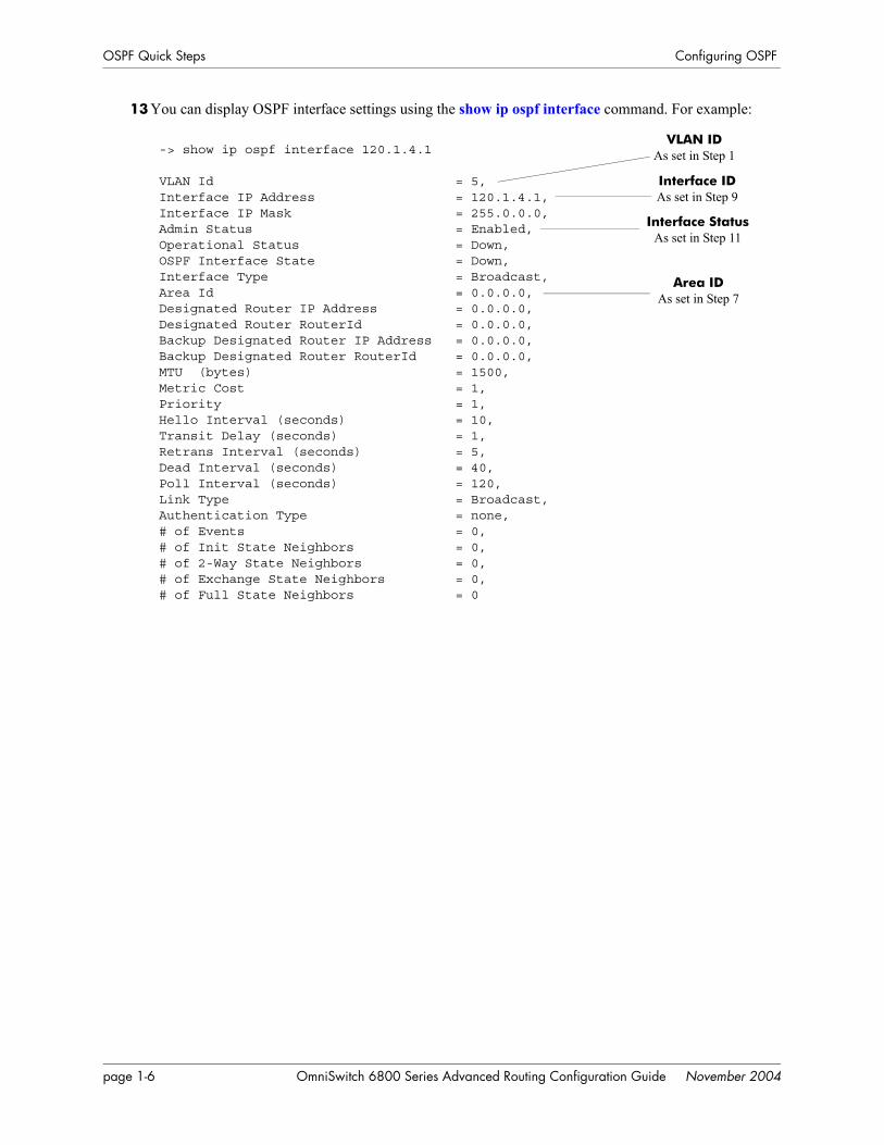
13 You can display OSPF interface settings using the show ip ospf interface command. For example:
-> show ip ospf interface 120.1.4.1
VLAN Id = 5,Interface IP Address = 120.1.4.1,Interface IP Mask = 255.0.0.0,Admin Status = Enabled,Operational Status = Down,OSPF Interface State = Down,Interface Type = Broadcast,Area Id = 0.0.0.0,Designated Router IP Address = 0.0.0.0,Designated Router RouterId = 0.0.0.0,Backup Designated Router IP Address = 0.0.0.0,Backup Designated Router RouterId = 0.0.0.0,MTU (bytes) = 1500,Metric Cost = 1,Priority = 1,Hello Interval (seconds) = 10,Transit Delay (seconds) = 1,Retrans Interval (seconds) = 5,Dead Interval (seconds) = 40,Poll Interval (seconds) = 120,Link Type = Broadcast,Authentication Type = none,# of Events = 0,# of Init State Neighbors = 0,# of 2-Way State Neighbors = 0,# of Exchange State Neighbors = 0,# of Full State Neighbors = 0
VLAN ID As set in Step 1
Interface ID As set in Step 9
Interface StatusAs set in Step 11
Area ID As set in Step 7
page 1-6 OmniSwitch 6800 Series Advanced Routing Configuration Guide November 2004

Configuring OSPF OSPF Overview
OSPF OverviewOpen Shortest Path First routing (OSPF) is a shortest path first (SPF), or link-state, protocol. OSPF is an interior gateway protocol (IGP) that distributes routing information between routers in a Single Autono-mous System (AS). OSPF chooses the least-cost path as the best path.
Each participating router distributes its local state (i.e., the router’s usable interfaces, local networks, and reachable neighbors) throughout the AS by flooding. In a link-state protocol, each router maintains a data-base describing the entire topology. This database is built from the collected link state advertisements of all routers. Each multi-access network that has at least two attached routers has a designated router and a backup designated router. The designated router floods a link state advertisement for the multi-access network.
When a router starts, it uses the OSPF Hello Protocol to discover neighbors. The router sends Hello pack-ets to its neighbors, and in turn receives their Hello packets. On broadcast and point-to-point networks, the router dynamically detects its neighboring routers by sending Hello packets to a multicast address. On nonbroadcast and point-to-multipoint networks, some configuration information is necessary in order to configure neighbors. On all networks (broadcast or nonbroadcast), the Hello Protocol also elects a desig-nated router for the network.
OSPF Hello Protocol
The router will attempt to form full adjacencies with all of its newly acquired neighbors. Only some pairs, however, will be successful in forming full adjacencies. Topological databases are synchronized between pairs of fully adjacent routers.
Adjacencies control the distribution of routing protocol packets. Routing protocol packets are sent and received only on adjacencies. In particular, distribution of topological database updates proceeds along adjacencies.
Link state is also advertised when a router’s state changes. A router’s adjacencies are reflected in the contents of its link state advertisements. This relationship between adjacencies and link state allows the protocol to detect downed routers in a timely fashion.
Link state advertisements are flooded throughout the AS. The flooding algorithm ensures that all routers have exactly the same topological database. This database consists of the collection of link state advertise-ments received from each router belonging to the area. From this database each router calculates a short-est-path tree, with itself as root. This shortest-path tree in turn yields a routing table for the protocol.
Hello. Please respond...
Are you a neighbor...Hello. Please respond...
Are you a neighbor...
My link state is... My link state is...
OmniSwitch 6800 Series Advanced Routing Configuration Guide November 2004 page 1-7

OSPF Overview Configuring OSPF
OSPF AreasOSPF allows collections of contiguous networks and hosts to be grouped together as an area. Each area runs a separate copy of the basic link-state routing algorithm (usually called SPF). This means that each area has its own topological database, as explained in the previous section.
OSPF Intra-Area and Inter-Area Routing
An area’s topology is visible only to the members of the area. Conversely, routers internal to a given area know nothing of the detailed topology external to the area. This isolation of knowledge enables the proto-col to reduce routing traffic by concentrating on small areas of an AS, as compared to treating the entire AS as a single link-state domain.
Areas cause routers to maintain a separate topological database for each area to which they are connected. (Routers connected to multiple areas are called area border routers). Two routers belonging to the same area have identical area topological databases.
Different areas communicate with each other through a backbone. The backbone consists of routers with contacts between multiple areas. A backbone must be contiguous (i.e., it must be linked to all areas).
The backbone is responsible for distributing routing information between areas. The backbone itself has all of the properties of an area. The topology of the backbone is invisible to each of the areas, while the back-bone itself knows nothing of the topology of the areas.
All routers in an area must agree on that area’s parameters. Since a separate copy of the link-state algo-rithm is run in each area, most configuration parameters are defined on a per-router basis. All routers belonging to an area must agree on that area’s configuration. Misconfiguration will keep neighbors from forming adjacencies between themselves, and OSPF will not function.
Inter-Area Routing
Backbone
Intra-AreaRouting
Intra-AreaRouting
Router 1
Router 2
Router 3
Router 4
Link State Messages
Link State Messages
Area 1 Area 2
Area 2
page 1-8 OmniSwitch 6800 Series Advanced Routing Configuration Guide November 2004

Configuring OSPF OSPF Overview
Classification of RoutersWhen an AS is split into OSPF areas, the routers are further divided according to function into the follow-ing four overlapping categories:
• Internal routers. A router with all directly connected networks belonging to the same area. These routers run a single copy of the SPF algorithm.
• Area border routers. A router that attaches to multiple areas. Area border routers run multiple copies of the SPF algorithm, one copy for each attached area. Area border routers condense the topological information of their attached areas for flooding to other areas.
• Backbone routers. A router that has an interface to the backbone. This includes all routers that inter-face to more than one area (i.e., area border routers). However, backbone routers do not have to be area border routers. Routers with all interfaces connected to the backbone are considered to be internal rout-ers.
• AS boundary routers. A router that exchanges routing information with routers belonging to other Autonomous Systems. Such a router has AS external routes that are advertised throughout the Autono-mous System. The path to each AS boundary router is known by every router in the AS. This classifi-cation is completely independent of the previous classifications (i.e., internal, area border, and backbone routers). AS boundary routers may be internal or area border routers, and may or may not participate in the backbone.
Virtual LinksIt is possible to define areas in such a way that the backbone is no longer contiguous. (This is not an ideal OSPF configuration, and maximum effort should be made to avoid this situation.) In this case the system administrator must restore backbone connectivity by configuring virtual links.
Virtual links can be configured between any two backbone routers that have a connection to a common non-backbone area. The protocol treats two routers joined by a virtual link as if they were connected by an unnumbered point-to-point network. The routing protocol traffic that flows along the virtual link uses intra-area routing only, and the physical connection between the two routers is not managed by the network administrator (i.e., there is no dedicated connection between the routers as there is with the OSPF backbone).
OSPF Routers Connected with a Virtual Link
In the above diagram, Router A and Router B are connected via a virtual link in Area 1, which is known as a transit area. See “Creating Virtual Links” on page 1-23 for more information.
Router A Router B
Backbone Virtual Link
Area 1
Backbone
OmniSwitch 6800 Series Advanced Routing Configuration Guide November 2004 page 1-9

OSPF Overview Configuring OSPF
Stub AreasOSPF allows certain areas to be configured as stub areas. A stub area is an area with routers that have no AS external Link State Advertisements (LSAs).
In order to take advantage of the OSPF stub area support, default routing must be used in the stub area. This is accomplished by configuring only one of the stub area’s border routers to advertise a default route into the stub area. The default routes will match any destination that is not explicitly reachable by an intra-area or inter-area path (i.e., AS external destinations).
OSPF Stub Area
Area 1 and Area 3 could be configured as stub areas. Stub areas are configured using the OSPF ip ospf area command, described in “Creating an Area” on page 1-17. For more overview information on areas, see “OSPF Areas” on page 1-8.
The OSPF protocol ensures that all routers belonging to an area agree on whether the area has been config-ured as a stub. This guarantees that no confusion will arise in the flooding of AS external advertisements.
Two restrictions on the use of stub areas are:
• Virtual links cannot be configured through stub areas.
• AS boundary routers cannot be placed internal to stub areas.
Area 3(stub)
Area 2Area 1(stub)
Backbone
Backbone
page 1-10 OmniSwitch 6800 Series Advanced Routing Configuration Guide November 2004

Configuring OSPF OSPF Overview
Not-So-Stubby-AreasNSSA, or not-so-stubby area, is an extension to the base OSPF specification and is defined in RFC 1587. An NSSA is similar to a stub area in many ways: AS-external LSAs are not flooded into an NSSA and virtual links are not allowed in an NSSA. The primary difference is that selected external routing informa-tion can be imported into an NSSA and then redistributed into the rest of the OSPF routing domain. These routes are imported into the NSSA using a new LSA type: Type-7 LSA. Type-7 LSAs are flooded within the NSSA and are translated at the NSSA boundary into AS-external LSAs so as to convey the external routing information to other areas.
NSSAs enable routers with limited resources to participate in OSPF routing while also allowing the import of a selected number of external routes into the area. For example, an area which connects to a small external routing domain running RIP may be configured as an NSSA. This will allow the import of RIP routes into this area and the rest of the OSPF routing domain and at the same time, prevent the flooding of other external routing information (learned, for example, through RIP) into this area.
All routers in an NSSA must have their OSPF area defined as an NSSA. To configure otherwise will ensure that the router will be unsuccessful in establishing an adjacent in the OSPF domain.
Equal Cost Multi-Path (ECMP) RoutingUsing information from its continuously updated databases, OSPF calculates the shortest path to a given destination. Shortest path is determined from metric values at each hop along a path. At times, two or more paths to the same destination will have the same metric cost.
In the network illustration below, there are two paths from Source router A to Destination router B. One path traverses two hops at routers X and Y and the second path traverses two hops at M and N. If the total cost through X and Y to B is the same as the cost via M and N to B, then these two paths have equal cost. In this version of OSPF both paths will be stored and used to transmit data.
Multiple Equal Cost Paths
Delivery of packets along equal paths is based on flows rather than a round-robin scheme. Equal cost is determined based on standard routing metrics. However, other variables, such as line speed, are not considered. So it is possible for OSPF to decide two paths have an equal cost even though one may contain faster links than another.
Source (A) Destination (B)
X Y
M N
A-> X-> Y-> B = A-> M-> N-> B
OmniSwitch 6800 Series Advanced Routing Configuration Guide November 2004 page 1-11

OSPF Overview Configuring OSPF
Non Broadcast OSPF RoutingOSPF can operate in two modes on non-broadcast networks: NBMA and point-to-multipoint. The inter-face type for the corresponding network segment should be set to non broadcast or point-to-multipoint, respectively.
For non-broadcast networks neighbors should be statically configured. For NBMA neighbors the eligibil-ity option must be enabled for the neighboring router to participate in Designated Router (DR) election.
For the correct working of an OSPF NBMA network, a fully meshed network is mandatory. Also, the neighbor eligibility configuration for a router on every other router should match the routers interface priority configuration.
See “Configuring Static Neighbors” on page 1-28 for more information and setting up static neighbors.
Graceful Restart on Stacks with Redundant SwitchesOmniSwitch 6800 Series stacks with two or more switches can support redundancy where if the primary switch fails or goes offline for any reason, the secondary switch is instantly notified. The secondary switch automatically assumes the primary role. This switch between the primary and secondary switches is known as takeover.
When a takeover occurs, which can be planned (e.g., the users performs the takeover) or unplanned (e.g., the primary switch unexpectedly fails), an OSPF router must reestablish full adjacencies with all its previ-ously fully adjacent neighbors. This time period between the restart and the reestablishment of adjacen-cies is termed graceful restart.
In the network illustration below, a helper router, Router Y, monitors the network for topology changes. As long as there are none, it continues to advertise its LSAs as if the restarting router, Router X, had remained in continuous OSPF operation (i.e., Router Y’s LSAs continue to list an adjacency to Router X over network segment S, regardless of the adjacency’s current synchronization state.)
OSPF Graceful Restart Helping and Restarting Router Example
Restarting Router X
Network Segment S
Helping Router Y
Router A
Router B
Router C
page 1-12 OmniSwitch 6800 Series Advanced Routing Configuration Guide November 2004

Configuring OSPF OSPF Overview
If the restarting router, Router X, was the Designated Router (DR) on network segment S when the help-ing relationship began, the helper neighbor, Router Y, maintains Router X as the DR until the helping rela-tionship is terminated. If there are multiple adjacencies with the restarting Router X, Router Y will act as a helper on all other adjacencies.
Note. See “Configuring Redundant Switches in a Stack for Graceful Restart” on page 1-29 for more infor-mation on configuring graceful restart.
OmniSwitch 6800 Series Advanced Routing Configuration Guide November 2004 page 1-13

Configuring OSPF Configuring OSPF
Configuring OSPFConfiguring OSPF on a router requires several steps. Depending on your requirements, you may not need to perform all of the steps listed below.
By default, OSPF is disabled on the router. Configuring OSPF consists of these tasks:
• Set up the basics of the OSPF network by configuring the required VLANs, assigning ports to the VLANs, and assigning router identification numbers to the routers involved. This is described in “Preparing the Network for OSPF” on page 1-15.
• Enable OSPF. When the image file for advanced routing is installed, you must load the code and enable OSPF. The commands for enabling OSPF are described in “Activating OSPF” on page 1-16.
• Create an OSPF area and the backbone. The commands to create areas and backbones are described in “Creating an OSPF Area” on page 1-17.
• Set area parameters (optional). OSPF will run with the default area parameters, but different networks may benefit from modifying the parameters. Modifying area parameters is described in “Configuring Stub Area Default Metrics” on page 1-19.
• Create OSPF interfaces. OSPF interfaces are created and assigned to areas. Creating interfaces is described in “Creating an Interface” on page 1-20, and assigning interfaces is described in “Assigning an Interface to an Area” on page 1-20.
• Set interface parameters (optional). OSPF will run with the default interface parameters, but different networks may benefit from modifying the parameters. Also, it is possible to set authentication on an interface. Setting interface authentication is described in “Interface Authentication” on page 1-21, and modifying interface parameters is described in “Modifying Interface Parameters” on page 1-22.
• Configure virtual links (optional). A virtual link is used to establish backbone connectivity when two backbone routers are not physically contiguous. To create a virtual link, see “Creating Virtual Links” on page 1-23.
• Create a redistribution policy (optional). A redistribution policy allows for the control of how routes are advertised into OSPF from outside the Autonomous System. Once a policy is created, redistribu-tion must be enabled. Creating a redistribution policy is described in “Creating A Redistribution Policy” on page 1-25, and enabling redistribution is described in “Enabling Redistribution” on page 1-24.
• Create redistribution filters (optional). A redistribution filter controls whether routes are advertised in the OSPF network. Creating a redistribution filter is described in “Creating a Redistribution Filter” on page 1-25.
• Configuring router capabilities (optional). There are several commands that influence router operation. These are covered briefly in a table in “Configuring Router Capabilities” on page 1-27.
• Creating static neighbors (optional). These commands allow you to statically configure neighbors. See “Configuring Static Neighbors” on page 1-28.
• Configuring redundant switches for graceful OSPF restart (optional). Configuring switches with redun-dant switches for graceful restart is described in “Configuring Redundant Switches in a Stack for Graceful Restart” on page 1-29.
At the end of the chapter is a simple OSPF network diagram with instructions on how it was created on a router-by-router basis. See “OSPF Application Example” on page 1-30 for more information.
page 1-14 OmniSwitch 6800 Series Advanced Routing Configuration Guide November 2004

Configuring OSPF Configuring OSPF
Preparing the Network for OSPFOSPF operates on top of normal switch functions, using existing ports, virtual ports, VLANs, etc. The following network components should already be configured:
• Configure VLANs that are to be used in the OSPF network. VLANS should be created for both the backbone interfaces and all other connected devices that will participate in the OSPF network. A VLAN should exist for each instance in which the backbone connects two routers. VLAN configura-tion is described in “Configuring VLANs,” in the OmniSwitch 6800 Series Network Configuration Guide.
• Assign IP interfaces to the VLANs. IP interfaces, or router ports, must be assigned to the VLAN. Assigning IP interfaces is described in “Configuring VLANs,” in the OmniSwitch 6800 Series Network Configuration Guide.
• Assign ports to the VLANs. The physical ports participating in the OSPF network must be assigned to the created VLANs. Assigning ports to a VLAN is described in “Assigning Ports to VLANs,” in the OmniSwitch 6800 Series Network Configuration Guide.
• Set the router identification number. (optional) The routers participating in the OSPF network must be assigned a router identification number. This number can be any number, as long as it is in standard dotted decimal format (e.g., 1.1.1.1). Router identification number assignment is discussed in “Config-uring IP,” in the OmniSwitch 6800 Series Network Configuration Guide. If this is not done, the router identification number is automatically the primary interface address.
OmniSwitch 6800 Series Advanced Routing Configuration Guide November 2004 page 1-15

Configuring OSPF Configuring OSPF
Activating OSPFFor OSPF to run on the router, the advanced routing image must be installed. (For information on how to install image files, see the OmniSwitch 6800 Series Switch Management Guide.)
After the image file has been installed onto the router, you will need to load the OSPF software into memory and enable it, as described below.
Loading the Software
To load the OSPF software into the router’s running configuration, enter the ip load ospf command at the system prompt:
-> ip load ospf
The OPSF software is now loaded into memory, and can be enabled.
Enabling OSPF
Once the OSPF software has been loaded into the router’s running configuration (either through the CLI or on startup), it must be enabled. To enable OSPF on a router, enter the ip ospf status command at the CLI prompt, as shown:
-> ip ospf status enable
Once OSPF is enabled, you can begin to set up OSPF parameters. To disable OSPF, enter the following:
-> ip ospf status disable
Removing OSPF from Memory
To remove OSPF from the router memory, it is necessary to manually edit the boot.cfg file. The boot.cfg file is an ASCII text-based file that controls many of the switch parameters. Open the file and delete all references to OSPF.
For the operation to take effect the switch needs to be rebooted.
page 1-16 OmniSwitch 6800 Series Advanced Routing Configuration Guide November 2004

Configuring OSPF Configuring OSPF
Creating an OSPF AreaOSPF allows a set of network devices in an AS system to be grouped together in areas.
There can be more than one router in an area. Likewise, there can be more than one area on a single router (in effect, making the router the Area Border Router (ABR) for the areas involved), but standard network-ing design does not recommended that more than three areas be handled on a single router.
Areas are named using 32-bit dotted decimal format (e.g., 1.1.1.1). Area 0.0.0.0 is reserved for the back-bone.
Creating an Area
To create an area and associate it with a router, enter the ip ospf area command with the area identifica-tion number at the CLI prompt, as shown:
-> ip ospf area 1.1.1.1
Area 1.1.1.1 will now be created on the router with the default parameters.
The backbone is always area 0.0.0.0. To create this area on a router, you would use the above command, but specify the backbone, as shown:
-> ip ospf area 0.0.0.0
The backbone would now be attached to the router, making it an Area Border Router (ABR).
Enabling an Area
Once an area is created, it must be enabled using the ip ospf area status command, as shown:
-> ip ospf area 0.0.0.0 status enable
Specifying an Area Type
When creating areas, an area type can be specified (normal, stub, or NSSA). Area types are described above in “OSPF Areas” on page 1-8. To specify an area type, use the ip ospf area command as shown:
-> ip ospf area 1.1.1.1 type stub
Note. By default, an area is a normal area. The type keyword would be used to change a stub or NSSA area into a normal area.
OmniSwitch 6800 Series Advanced Routing Configuration Guide November 2004 page 1-17

Configuring OSPF Configuring OSPF
Enabling and Disabling Summarization
Summarization can also be enabled or disabled when creating an area. Enabling summarization allows for ranges to be used by Area Border Routers (ABRs) for advertising routes as a single route rather than multiple routes, while disabling summarization prevents set ranges from functioning in stub and NSSA areas. (Configuring ranges is described in “Setting Area Ranges” on page 1-19.)
For example, to enable summarization for Area 1.1.1.1, enter the following:
-> ip ospf area 1.1.1.1 summary enable
To disable summarization for the same area, enter the following:
-> ip ospf area 1.1.1.1 summary disable
Note. By default, an area has summarization enabled. Disabling summarization for an area is useful when ranges need to be deactivated, but not deleted.
Displaying Area Status
You can check the status of the newly created area by using the show command, as demonstrated:
-> show ip ospf area 1.1.1.1
or
-> show ip ospf area
The first example gives specifics about area 1.1.1.1, and the second example shows all areas configured on the router.
To display a stub area’s parameters, use the show ip ospf area stub command as follows:
-> show ip ospf area 1.1.1.1 stub
Deleting an Area
To delete an area, enter the ip ospf area command as shown:
-> no ip ospf area 1.1.1.1
page 1-18 OmniSwitch 6800 Series Advanced Routing Configuration Guide November 2004

Configuring OSPF Configuring OSPF
Configuring Stub Area Default Metrics
The default metric configures the type of cost metric that a default area border router (ABR) will adver-tise in the default summary Link State Advertisement (LSA). Use the ip ospf area default-metric command to create or delete a default metric for stub or Not So Stubby Area (NSSA) area. Specify the stub area and select a cost value or a route type, as shown:
-> ip ospf area 1.1.1.1 default-metric 0 cost 50
or
-> ip ospf area 1.1.1.1 default-metric 0 type type1
A route has a preset metric associated to it depending on its type. The first example, the stub area is given a default metric of 0 (this is Type of Service 0) and a cost of 50 added to routes from the area. The second example specifies that the cost associated with Type 1 routes should be applied to routes from the area.
Note. At this time, only the default metric of ToS 0 is supported.
To remove the area default-metric setting, enter the ip ospf area default-metric command using the no command, as shown:
-> no ip ospf area 1.1.1.1 default-metric 0
Setting Area Ranges
Area ranges are used to summarize many area routes into a single advertisement at an area boundary. Ranges are advertised as summaries or NSSAs. Ranges also act as filters that either allow the summary to be advertised or not. Ranges are created using the ip ospf area range command. An area and the summary IP address and IP mask must be specified. For example, to create a summary range with IP address 192.5.40.1 and an IP mask of 255.255.255.0 for area 1.1.1.1, the following commands would be entered at the CLI prompt:
-> ip ospf area 1.1.1.1 range summary 192.5.40.1 255.255.255.0
-> ip ospf area 1.1.1.1 range summary 192.5.40.1 255.255.255.0 effect noMatching
To view the configured ranges for an area, use the show ip ospf area range command as demonstrated:
-> show ip ospf area 1.1.1.1 range
OmniSwitch 6800 Series Advanced Routing Configuration Guide November 2004 page 1-19

Configuring OSPF Configuring OSPF
Creating OSPF InterfacesOnce areas have been established, interfaces need to be created and assigned to the areas.
Creating an Interface
To create an interface, enter the ip ospf interface command with an IP address, as shown:
-> ip ospf interface 120.5.80.1
The interface can be deleted the by using the no keyword, as shown:
-> no ip ospf interface 120.5.80.1
Assigning an Interface to an Area
Once an interface is created, it must be assigned to an area. (Creating areas is described in “Creating an Area” on page 1-17 above.)
To assign an interface to an area, enter the ip ospf interface area command with the interface IP address and area identification number at the CLI prompt. For example to add interface 120.5.80.1 to area 1.1.1.1, enter the following:
-> ip ospf interface 120.5.80.1 area 1.1.1.1
An interface can be removed from an area by reassigning it to a new area.
Once an interface has been created and enabled, you can check its status and configuration by using the show command, as demonstrated:
-> show ip ospf interface 120.5.80.1
Instructions for configuring authentication are given in “Interface Authentication” on page 1-21, and inter-face parameter options are described in “Modifying Interface Parameters” on page 1-22.
Activating an Interface
Once the interface is created and assigned to an area, it must be activated using the ip ospf interface status command, as shown:
-> ip ospf interface 120.5.80.1 status enable
The interface can be disabled using the disable keyword in place of the enable keyword.
page 1-20 OmniSwitch 6800 Series Advanced Routing Configuration Guide November 2004

Configuring OSPF Configuring OSPF
Interface Authentication
OSPF allows for the use of authentication on configured interfaces. When authentication is enabled, only neighbors using the same type of authentication and the matching passwords or keys can communicate.
There are two types of authentication: simple and MD5. Simple authentication requires only a text string as a password, while MD5 is a form of encrypted authentication that requires a key and a password. Both types of authentication require the use of more than one command.
Simple Authentication
To enable simple authentication on an interface, enter the ip ospf interface auth-type command with the specified interface, as shown:
-> ip ospf interface 120.5.80.1 auth-type simple
Once simple authentication is enabled, the password must be set with the ip ospf interface auth-key command, as shown:
-> ip ospf interface 120.5.80.1 auth-key test
In the above instance, only other interfaces with simple authentication and a password of “test” will be able to use the configured interface.
MD5 Encryption
To configure the same interface for MD5 encryption, enter the ip ospf interface auth-type as shown:
-> ip ospf interface 120.5.80.1 auth-type md5
Once MD5 authentication is set, a key identification and key string must be set with the ip ospf interface md5 key command. For example to set interface 120.5.80.1 to use MD5 authentication with a key identifi-cation of 7 and key string of “test”, enter:
-> ip ospf interface 120.5.80.1 md5 7
and
-> ip ospf interface 120.5.80.1 md5 7 key "test"
Note that setting the key ID and key string must be done in two separate commands. Once the key ID and key string have been set, MD5 authentication is enabled. To disable it, use the ip ospf interface md5 command, as shown:
-> ip ospf interface 120.5.80.1 md5 7 disable
To remove all authentication, enter the ip ospf interface auth-type as follows:
-> ip ospf interface 120.5.80.1 auth-type none
OmniSwitch 6800 Series Advanced Routing Configuration Guide November 2004 page 1-21

Configuring OSPF Configuring OSPF
Modifying Interface Parameters
There are several interface parameters that can be modified on a specified interface. Most of these deal with timer settings.
The cost parameter and the priority parameter help to determine the cost of the route using this interface, and the chance that this interface’s router will become the designated router, respectively.
The following table shows the various interface parameters that can be set:
These parameters can be added any time. (See “Creating OSPF Interfaces” on page 1-20 for more informa-tion.) For example, to set an the dead interval to 50 and the cost to 100 on interface 120.5.80.1, enter the following:
-> ip ospf interface 120.5.80.1 dead-interval 50 cost 100
To set an the poll interval to 25, the priority to 100, and the retransmit interval to 10 on interface 120.5.80.1, enter the following:
-> ip ospf interface 120.5.80.1 poll-interval 25 priority 100 retrans-interval 10
To set the hello interval to 5000 on interface 120.5.80.1, enter the following:
-> ip ospf interface 120.5.80.1 hello-interval 5000
To reset any parameter to its default value, enter the keyword with no parameter value, as shown:
-> ip ospf interface 120.5.80.1 dead-interval
Note. Although you can configure several parameters at once, you can only reset them to the default one at a time.
ip ospf interface dead-interval Configures OSPF interface dead interval. If no hello packets are received in this interval from a neighboring router the neighbor is con-sidered dead.
ip ospf interface hello-interval Configures the OSPF interface interval for NBMA segments.ip ospf interface cost Configures the OSPF interface cost. A cost metric refers to the net-
work path preference assigned to certain types of traffic.ip ospf interface poll-interval Configures the OSPF poll interval.ip ospf interface priority Configures the OSPF interface priority. The priority number helps
determine if this router will become the designated router.ip ospf interface retrans-interval Configures OSPF interface retransmit interval. The number of sec-
onds between link state advertisement retransmissions for adjacencies belonging to this interface.
ip ospf interface transit-delay Configures the OSPF interface transit delay. The estimated number of seconds required to transmit a link state update over this interface.
page 1-22 OmniSwitch 6800 Series Advanced Routing Configuration Guide November 2004
Configuring OSPF Configuring OSPF
Creating Virtual LinksA virtual link is a link between two backbones through a transit area. Use the ip ospf virtual-link command to create or delete a virtual link.
Accepted network design theory states that virtual links are the option of last resort. For more information on virtual links, see “Virtual Links” on page 1-9 and refer to the figure on page 1-9.
Creating a Virtual Link
To create a virtual link, commands must be submitted to the routers at both ends of the link. The router being configured should point to the other end of the link, and both routers must have a common area.
When entering the ip ospf virtual-link command, it is necessary to enter the Router ID of the far end of the link, and the area ID that both ends of the link share.
For example, a virtual link needs to be created between Router A (router ID 1.1.1.1) and Router B (router ID 2.2.2.2). We must:
1 Establish a transit area between the two routers using the commands discussed in “Creating an OSPF Area” on page 1-17 (in this example, we will use Area 0.0.0.1).
2 Then use the ip ospf virtual-link command on Router A as shown:
ip ospf virtual-link 0.0.0.1 2.2.2.2
3 Next, enter the following command on Router B:
ip ospf virtual-link 0.0.0.1 1.1.1.1
Now there is a virtual link across Area 0.0.0.1 linking Router A and Router B.
4 To display virtual links configured on a router, enter the following show command:
show ip ospf virtual-link
5 To delete a virtual link, enter the ip ospf virtual-link command with the area and far end router infor-mation, as shown:
no ip ospf virtual-link 0.0.0.1 2.2.2.2
Modifying Virtual Link Parameters
There are several parameters for a virtual link (such as authentication type and cost) that can be modified at the time of the link creation. They are described in the ip ospf virtual-link command description.These parameters are identical in function to their counterparts in the section “Modifying Interface Parameters” on page 1-22.
OmniSwitch 6800 Series Advanced Routing Configuration Guide November 2004 page 1-23

Configuring OSPF Configuring OSPF
Creating Redistribution Policies and FiltersRedistribution in OSPF controls the way routes are learned and distributed in the OSPF network. Non OSPF routers can be advertised into the OSPF network as AS-external or NSSA-external routes. NSSA-external routes are advertised only in OSPF-NSSA areas. Redistribution policies are set on Autonomous System Boundary Routers (ASBRs) and control how routes from outside the Autonomous System (AS) are learned and distributed. Redistribution Filters are set on any OSPF router and control how routes on the router are distributed to other routers in the OSPF network.
To set up redistribution on a router:
1 Specify the router as an ASBR, as described in “Specifying an Autonomous System Boundary Router” on page 1-24. (For redistribution policies only.)
2 Enable redistribution, as described in “Enabling Redistribution” on page 1-24.
3 Create a redistribution policy or filter, as described in “Creating A Redistribution Policy” on page 1-25 and “Creating a Redistribution Filter” on page 1-25.
Specifying an Autonomous System Boundary Router
Redistribution policies can only be created on ASBRs. ASBRs are routers that are directly connected to a network outside of the AS (e.g., the internet). To configure a router to be an ASBR, enter the ip ospf asbr command at the CLI prompt, as shown:
-> ip ospf asbr
You can check to see if a router is an ASBR router by using the show ip ospf command.
Enabling Redistribution
Before using any type of redistribution policy or filter, you must enable redistribution on the router, using the ip ospf redist status command. To enable redistribution, enter the command at the CLI prompt as shown:
-> ip ospf redist status enable
To disable redistribution, enter the command as shown:
-> ip ospf redist status disable
page 1-24 OmniSwitch 6800 Series Advanced Routing Configuration Guide November 2004

Configuring OSPF Configuring OSPF
Creating A Redistribution Policy
Once a router is set as an ASBR and redistribution is enabled, a redistribution policy can be created. This is done using the ip ospf redist command. When setting up a redistribution policy, choose the type of route or protocol that will be redistributed as an OSPF route in the OSPF network. For example, to redis-tribute RIP routes, enter the following:
-> ip ospf redist rip
To redistribute static routes, enter the following:
-> ip ospf redist static
A cost metric can be added to the redistributed route, either as a set number or by specifying a route type (route types have preassigned metrics and other rule that control how they are redistributed). For example, to add a cost metric of 50 to RIP routes, enter the following:
-> ip ospf redist rip metric 50
To set RIP route redistribution as type 1 routes, enter the following:
-> ip ospf redist rip metric-type type1
For more information on route types, see the ip ospf redist command in the OmniSwitch CLI Reference Guide.
To display the redistribution policies on a router, enter the show ip ospf redist command at the CLI prompt.
To delete a redistribution policy, enter the ip ospf redist command with the route or protocol type, and the no keyword, as shown:
-> no ip ospf redist rip
Creating a Redistribution Filter
Redistribution filters are used by routers to control which routes are advertised to the rest of the network. Filters can be created on any OSPF router that has redistribution enabled.
Filters are created using the ip ospf redist-filter command.When using a filter, a route or protocol type must be specified, along with the IP address and mask. Only routes matching the specified criteria will be advertised. For example, to create a filter for RIP routes 1.1.0.0 with a mask of 255.255.0.0, enter the following:
-> ip ospf redist-filter rip 1.1.0.0 255.255.0.0
Filters can also be used to prevent routes from being advertised by using the effect keyword. Using the above example, to prevent RIP routes learned from 1.1.0.0 being advertised, enter the following:
-> ip ospf redist-filter rip 1.1.0.0 255.255.0.0 effect deny
This filter would stop the advertisement of RIP routes learned within the range 1.1.0.0 with a mask of 255.255.0.0. All other routes would be advertised normally.
Note. By default, filters are set to permit. If permit is the filter action desired, it is not necessary to use the effect keyword.
OmniSwitch 6800 Series Advanced Routing Configuration Guide November 2004 page 1-25
Configuring OSPF Configuring OSPF
In certain cases, redistribution can either be an adjacent route or a subnet. In these cases, the redistributed route can correspond to several routes. It is possible to advertise these routes separately or not with the redist-control keyword.
If it is desired to advertise only an aggregated route instead of all the routes to comprise the aggregate, use the ip ospf redist-filter command with the redist-control aggregate keyword, as shown (you will also need to enter the route information as above):
-> ip ospf redist-filter rip 1.1.0.0 255.255.0.0 redist-control aggregate
If it is desired that the subnet routes that fall within the aggregate range should not be advertised, use the ip ospf redist-filter command with the redist-control keyword as shown (you will also need to enter the route information as above):
-> ip ospf redist-filter rip 1.1.0.0 255.255.0.0 redist-control no-subnets
Note. By default, filters are set to allow subnet routes to be advertised. If this is the filter action desired, it is not necessary to use the redist-control keyword.
A cost metric and route tag can be assigned to the routes that are allowed to pass through the filter, by using the metric and route-tag keywords, as shown (these options are described in the ip ospf redist-filter command):
-> ip ospf redist-filter rip 1.1.0.0 255.255.0.0 metric 100 route-tag 5
To display all of the configured filters on a router, enter the show ip ospf redist-filter command as shown:
-> show ip ospf redist-filter
To display the configured filters for a specific route or protocol type, enter the show command and the route or protocol type:
-> show ip ospf redist-filter rip
To display a specific filter, enter the show command with the route or protocol type and the ip address and mask, as demonstrated:
-> show ip ospf redist-filter rip 1.1.0.0 255.255.0.0
To delete a redistribution filter, enter the ip ospf redist-filter command with the route or protocol type and its associated IP address and mask, as shown:
-> no ip ospf redist-filter rip 1.1.0.0 255.255.0.0
page 1-26 OmniSwitch 6800 Series Advanced Routing Configuration Guide November 2004

Configuring OSPF Configuring OSPF
Configuring Router CapabilitiesThe following list shows various commands that can be useful in tailoring a router’s performance capabili-ties. All of the listed parameters have defaults that are acceptable for running an OSPF network.
To configure a router parameter, enter the parameter at the CLI prompt with the new value or required variables. For example to set the exit overflow interval to 40, enter:
-> ip ospf exit-overflow-interval 40
To enable MTU checking, enter:
-> ip ospf mtu-checking
To set the route tag to 5, enter:
-> ip ospf route-tag 5
To set the SPF timer delay to 3 and the hold time to 6, enter:
-> ip ospf spf-timer delay 3 hold 6
To return a parameter to its default setting, enter the command with no parameter value, as shown:
-> ip ospf spf-timer
ip ospf exit-overflow-interval Sets the overflow interval value. The overflow interval is the time whereby the router will wait before attempting to leave the database overflow state.
ip ospf extlsdb-limit Sets a limit to the number of external Link State Databases entries learned by the router. An external LSDB entry is created when the router learns a link address that exists outside of its Autonomous System (AS).
ip ospf host Creates and deletes an OSPF entry for directly attached hosts.ip ospf mtu-checking Enables or disables the use of Maximum Transfer Unit (MTU) checking
on received OSPF database description packets. ip ospf route-tag Configures a tag value for Autonomous System External (ASE) routes
created.ip ospf spf-timer Configures timers for Shortest Path First (SPF) calculation.
OmniSwitch 6800 Series Advanced Routing Configuration Guide November 2004 page 1-27

Configuring OSPF Configuring OSPF
Configuring Static NeighborsIt is possible to configure neighbors statically on Non Broadcast Multi Access (NBMA), point-to-point, and point-to-multipoint networks.
NBMA requires all routers attached to the network to communicate directly (unicast), and every attached router in this network becomes aware of all of its neighbors through configuration. It also requires a Designated Router (DR) “eligibility” flag to be set for every neighbor.
To set up a router to use NBMA routing, follow the following steps:
1 Create an OSPF interface using the CLI command ip ospf interface and perform all the normal config-uration for the interface as with broadcast networks (attaching it to an area, enabling the status, etc.).
2 The OSPF interface type for this interface should be set to non-broadcast using the CLIip ospf interface type command. For example, to set interface 1.1.1.1 to be an NBMA interface, enter the following:
-> ip ospf interface 1.1.1.1 type non-broadcast
3 Configure static neighbors for every OSPF router in the network using the ip ospf neighbor command. For example, to create an OSPF neighbor with an IP address of 1.1.1.8 to be a static neighbor, enter the following:
-> ip ospf neighbor 1.1.1.8 eligible
The neighbor attaches itself to the right interface by matching the network address of the neighbor and the interface. If the interface has not yet been created, the neighbor gets attached to the interface as and when the interface comes up.
If this neighbor is not required to participate in DR election, configure it as non-eligible. The eligibility can be changed at any time as long as the interface it is attached to is in the disabled state.
page 1-28 OmniSwitch 6800 Series Advanced Routing Configuration Guide November 2004

Configuring OSPF Configuring OSPF
Configuring Redundant Switches in a Stack for Graceful RestartBy default, OSPF graceful restart is disabled. To configure OSPF graceful restart support use the ip ospf restart-support command by entering ip ospf restart-support followed by either planned-unplanned (the default) or planned-only.
For example, to modify OSPF graceful restart so that it only supports planned restarts enter:
-> ip ospf restart-support planned-only
To disable support for graceful restart use the no form of the ip ospf restart-support command by enter-ing:
-> no ip ospf restart-support
Continuous forwarding during a graceful restart depends on several factors. If the secondary module has a different router MAC than the primary module, or if one or more ports of a VLAN belonged to the primary module, spanning tree re-convergence might disrupt forwarding state, even though OSPF performs a graceful restart.
Note. Graceful restart is only supported on active ports (i.e., interfaces), which are on the secondary or idle switches in a stack during a takeover. It is not supported on ports on a primary switch in a stack.
Optionally, you can configure graceful restart parameters with the following CLI commands:
For more information about graceful restart commands, see the “OSPF Commands” chapter in the OmniSwitch CLI Reference Guide.
ip ospf restart-interval Configures the grace period for achieving a graceful OSPF restart.ip ospf restart-helper status Administratively enables and disables the capability of an OSPF router
to operate in helper mode in response to a router performing a graceful restart.
ip ospf restart-helper strict-lsa-checking-status
Administratively enables and disables whether or not a changed Link State Advertisement (LSA) will result in termination of graceful restart by a helping router.
ip ospf restart initiate Initiates a planned graceful restart.
OmniSwitch 6800 Series Advanced Routing Configuration Guide November 2004 page 1-29

OSPF Application Example Configuring OSPF
OSPF Application ExampleThis section will demonstrate how to set up a simple OSPF network. It uses three routers, each with an area. Each router uses three VLANs. A backbone connects all the routers. This section will demonstrate how to set it up by explaining the necessary commands for each router.
The following diagram is a simple OSPF network. It will be created by the steps listed on the following pages.
Three Area OSPF Network
Backbone Area(Area 0.0.0.0)
Area 0.0.0.1Router 1
Router ID 1.1.1.1
Area 0.0.0.2Router 2
Router ID 20.0.0.1
Area 0.0.0.3Router 3
Router ID 3.3.3.3
VLAN 10Interface 10.0.0.1
VLAN 20Interface 20.0.0.1
VLAN 12Interface 12.x.x.x
VLAN 30Interface 30.0.0.1
VLAN 23Interface 23.x.x.x
VLAN 31Interface 31.x.x.x
page 1-30 OmniSwitch 6800 Series Advanced Routing Configuration Guide November 2004

Configuring OSPF OSPF Application Example
Step 1: Prepare the RoutersThe first step is to create the VLANs on each router, add an IP interface to the VLAN, assign a port to the VLAN, and assign a router identification number to the routers. For the backbone, the network design in this case uses slot 2, port 1 as the egress port and slot 2, port 2 as ingress port on each router. Router 1 connects to Router 2, Router 2 connects to Router 3, and Router 3 connects to Router 1 using 10/100 Ethernet cables.
Note. The ports will be statically assigned to the router, as a VLAN must have a physical port assigned to it in order for the router port to function. However, the router could be set up in such a way that mobile ports are dynamically assigned to VLANs using VLAN rules. See the chapter titled “Defining VLAN Rules” in the OmniSwitch 6800 Series Network Configuration Guide.
The commands setting up VLANs are shown below:
Router 1 (using ports 2/1 and 2/2 for the backbone, and ports 2/3-5 for end devices):
-> vlan 31-> vlan 31 router ip 31.0.0.1 255.0.0.0-> vlan 31 port default 2/1
-> vlan 12-> vlan 12 router ip 12.0.0.1 255.0.0.0-> vlan 12 port default 2/2
-> vlan 10-> vlan 10 router ip 10.0.0.1 255.0.0.0-> vlan 10 port default 2/3-5
-> ip router router-id 1.1.1.1
These commands created VLANs 31, 12, and 10.
• VLAN 31 handles the backbone connection from Router 1 to Router 3, using the IP router port 31.0.0.1 and physical port 2/1.
• VLAN 12 handles the backbone connection from Router 1 to Router 2, using the IP router port 12.0.0.1 and physical port 2/2.
• VLAN 10 handles the device connections to Router 1, using the IP router port 10.0.0.1 and physical ports 2/3-5. More ports could be added at a later time if necessary.
The router was assigned the Router ID of 1.1.1.1.
Router 2 (using ports 2/1 and 2/2 for the backbone, and ports 2/3-5 for end devices):
-> vlan 12-> vlan 12 router ip 12.0.0.2 255.0.0.0-> vlan 12 port default 2/1
-> vlan 23-> vlan 23 router ip 23.0.0.2 255.0.0.0-> vlan 23 port default 2/2
-> vlan 20-> vlan 20 router ip 20.0.0.2 255.0.0.0-> vlan 20 port default 2/3-5
OmniSwitch 6800 Series Advanced Routing Configuration Guide November 2004 page 1-31

OSPF Application Example Configuring OSPF
-> ip router router-id 2.2.2.2
These commands created VLANs 12, 23, and 20.
• VLAN 12 handles the backbone connection from Router 1 to Router 2, using the IP router port 12.0.0.2 and physical port 2/1.
• VLAN 23 handles the backbone connection from Router 2 to Router 3, using the IP router port 23.0.0.2 and physical port 2/2.
• VLAN 20 handles the device connections to Router 2, using the IP router port 20.0.0.2 and physical ports 2/3-5. More ports could be added at a later time if necessary.
The router was assigned the Router ID of 2.2.2.2.
Router 3 (using ports 2/1 and 2/2 for the backbone, and ports 2/3-5 for end devices)
-> vlan 23-> vlan 23 router ip 23.0.0.3 255.0.0.0-> vlan 23 port default 2/1
-> vlan 31-> vlan 31 router ip 31.0.0.3 255.0.0.0-> vlan 31 port default 2/2
-> vlan 30-> vlan 30 router ip 30.0.0.3 255.0.0.0-> vlan 30 port default 2/3-5
-> ip router router-id 3.3.3.3
These commands created VLANs 23, 31, and 30.
• VLAN 23 handles the backbone connection from Router 2 to Router 3, using the IP router port 23.0.0.3 and physical port 2/1.
• VLAN 31 handles the backbone connection from Router 3 to Router 1, using the IP router port 31.0.0.3 and physical port 2/2.
• VLAN 30 handles the device connections to Router 3, using the IP router port 30.0.0.3 and physical ports 2/3-5. More ports could be added at a later time if necessary.
The router was assigned the Router ID of 3.3.3.3.
Step 2: Enable OSPFThe next step is to load and enable OSPF on each router. The commands for this step are below (the commands are the same on each router):
-> ip load ospf-> ip ospf status enable
page 1-32 OmniSwitch 6800 Series Advanced Routing Configuration Guide November 2004

Configuring OSPF OSPF Application Example
Step 3: Create and Enable the Areas and BackboneNow the areas should be created and enabled. In this case, we will create an area for each router, and a backbone (area 0.0.0.0) that connects the areas.
The commands for this step are below:
Router 1
-> ip ospf area 0.0.0.0-> ip ospf area 0.0.0.0 status enable
-> ip ospf area 0.0.0.1-> ip ospf area 0.0.0.1 status enable
These commands created area 0.0.0.0 (the backbone) and area 0.0.0.1 (the area for Router 1). Both of these areas are also enabled.
Router 2
-> ip ospf area 0.0.0.0-> ip ospf area 0.0.0.0 status enable
-> ip ospf area 0.0.0.2-> ip ospf area 0.0.0.2 status enable
These commands created Area 0.0.0.0 (the backbone) and Area 0.0.0.2 (the area for Router 2). Both of these areas are also enabled.
Router 3
-> ip ospf area 0.0.0.0-> ip ospf area 0.0.0.0 status enable
-> ip ospf area 0.0.0.3-> ip ospf area 0.0.0.3 status enable
These commands created Area 0.0.0.0 (the backbone) and Area 0.0.0.3 (the area for Router 3). Both of these areas are also enabled.
Step 4: Create, Enable, and Assign InterfacesNext, OSPF interfaces must be created, enabled, and assigned to the areas. The OSPF interfaces should have the same IP address as the IP router ports created above in “Step 1: Prepare the Routers” on page 1-31.
Router 1
-> ip ospf interface 31.0.0.1-> ip ospf interface 31.0.0.1 area 0.0.0.0-> ip ospf interface 31.0.0.1 status enable
-> ip ospf interface 12.0.0.1-> ip ospf interface 12.0.0.1 area 0.0.0.0-> ip ospf interface 12.0.0.1 status enable
-> ip ospf interface 10.0.0.1-> ip ospf interface 10.0.0.1 area 0.0.0.1-> ip ospf interface 10.0.0.1 status enable
OmniSwitch 6800 Series Advanced Routing Configuration Guide November 2004 page 1-33

OSPF Application Example Configuring OSPF
IP router port 31.0.0.1 was associated to OSPF interface 31.0.0.1, enabled, and assigned to the backbone. IP router port 12.0.0.1 was associated to OSPF interface 12.0.0.1, enabled, and assigned to the backbone. IP router port 10.0.0.1 which connects to end stations and attached network devices, was associated to OSPF interface 10.0.0.1, enabled, and assigned to Area 0.0.0.1.
Router 2
-> ip ospf interface 12.0.0.2-> ip ospf interface 12.0.0.2 area 0.0.0.0-> ip ospf interface 12.0.0.2 status enable
-> ip ospf interface 23.0.0.2-> ip ospf interface 23.0.0.2 area 0.0.0.0-> ip ospf interface 23.0.0.2 status enable
-> ip ospf interface 20.0.0.2-> ip ospf interface 20.0.0.2 area 0.0.0.2-> ip ospf interface 20.0.0.2 status enable
IP router port 12.0.0.2 was associated to OSPF interface 12.0.0.2, enabled, and assigned to the backbone. IP router port 23.0.0.2 was associated to OSPF interface 23.0.0.2, enabled, and assigned to the backbone. IP router port 20.0.0.2, which connects to end stations and attached network devices, was associated to OSPF interface 20.0.0.2, enabled, and assigned to Area 0.0.0.2.
Router 3
-> ip ospf interface 23.0.0.3-> ip ospf interface 23.0.0.3 area 0.0.0.0-> ip ospf interface 23.0.0.3 status enable
-> ip ospf interface 31.0.0.3-> ip ospf interface 31.0.0.3 area 0.0.0.0-> ip ospf interface 31.0.0.3 status enable
-> ip ospf interface 30.0.0.3-> ip ospf interface 30.0.0.3 area 0.0.0.3-> ip ospf interface 30.0.0.3 status enable
IP router port 23.0.0.3 was associated to OSPF interface 23.0.0.3, enabled, and assigned to the backbone. IP router port 31.0.0.3 was associated to OSPF interface 31.0.0.3, enabled, and assigned to the backbone. IP router port 30.0.0.3, which connects to end stations and attached network devices, was associated to OSPF interface 30.0.0.3, enabled, and assigned to Area 0.0.0.3.
Step 5: Examine the NetworkAfter the network has been created, you can check various aspects of it using show commands:
• For OSPF in general, use the show ip ospf command.
• For areas, use the show ip ospf area command.
• For interfaces, use the show ip ospf interface command.
• To check for adjacencies formed with neighbors, use the show ip ospf neighbor command.
• For routes, use the show ip ospf routes command.
page 1-34 OmniSwitch 6800 Series Advanced Routing Configuration Guide November 2004

Configuring OSPF Verifying OSPF Configuration
Verifying OSPF ConfigurationTo display information about areas, interfaces, virtual links, redistribution, or OPSF in general, use the show commands listed in the following table:
For more information about the resulting displays form these commands, see the “OSPF Commands” chapter in the OmniSwitch CLI Reference Guide.
Examples of the show ip ospf, show ip ospf area, and show ip ospf interface command outputs are given in the section “OSPF Quick Steps” on page 1-4.
show ip ospf Displays OSPF status and general configuration parameters.show ip ospf border-routers Displays information regarding all or specified border routers.show ip ospf ext-lsdb Displays external Link State Advertisements from the areas to which the
router is attached.show ip ospf host Displays information on directly attached hosts.show ip ospf lsdb Displays LSAs in the Link State Database associated with each area.show ip ospf neighbor Displays information on OSPF non-virtual neighbor routersshow ip ospf redist-filter Displays OSPF redistribution filter attributes.show ip ospf redist Displays the specified redistribution instance that allows routes to be
redistributed into OSPF.show ip ospf routes Displays OSPF routes known to the router.show ip ospf virtual-link Displays virtual link information.show ip ospf virtual-neighbor Displays OSPF virtual neighbors.show ip ospf area Displays either all OSPF areas, or a specified OSPF area.show ip ospf area range Displays all or specified configured area address range summaries for
the given area.show ip ospf area stub Displays stub area status.show ip ospf interface Displays OSPF interface information.show ip ospf restart Displays the OSPF graceful restart related configuration and status.
OmniSwitch 6800 Series Advanced Routing Configuration Guide November 2004 page 1-35

Verifying OSPF Configuration Configuring OSPF
page 1-36 OmniSwitch 6800 Series Advanced Routing Configuration Guide November 2004

2 Configuring MulticastAddress Boundaries
Multicast boundaries confine scoped multicast addresses to a particular domain. Confining scoped addresses helps to ensure that multicast traffic passed within a multicast domain does not conflict with multicast users outside the domain.
In This ChapterThis chapter describes the basic components of scoped multicast boundaries and how to configure them through the Command Line Interface (CLI). CLI commands are used in the configuration examples; for more details about the syntax of commands, see the OmniSwitch CLI Reference Guide.
Configuration procedures described in this chapter include:
• Configuring multicast address boundaries—see page 2-7.
• Verifying the multicast address boundary configuration—see page 2-7.
For information about additional multicast routing commands, see the “Multicast Routing Commands” chapter in the OmniSwitch CLI Reference Guide.
OmniSwitch 6800 Series Advanced Routing Configuration Guide November 2004 page 2-1

Multicast Boundary Specifications Configuring Multicast Address Boundaries
Multicast Boundary Specifications
Note. If software routing is used, the number of total flows supported is variable, depending on the number of flows and the number of routes per flow.
To enable or disable IP multicast hardware routing, use the ip multicast hardware-routing command. For more information on this command, see the “Configuring IP Multicast Switching” chapter in the OmniSwitch 6800 Network Configuration Guide or the “IP Multicast Switching Commands” chapter in the OmniSwitch CLI Reference Guide.
Quick Steps for Configuring Multicast Address BoundariesUsing Existing Router Ports
1 Before attempting to configure a multicast address boundary, be sure that you have manually loaded the multicast protocol software for your network (e.g., PIM-SM or DVMRP). Otherwise, you will receive an error stating that “the specified application is not loaded.” To manually load multicast protocol soft-ware, use the ip load command. For example:
-> ip load pimsm
2 Configure a multicast address boundary for a VLAN interface using the ip mroute-boundary command. Information must include the interface IP address, followed by the multicast boundary address and the corresponding subnet mask. For example:
-> ip mroute-boundary 178.14.1.43 239.120.0.0 255.255.0.0
On New Router Ports
1 Be sure that you have loaded one of the dynamic routing features (e.g., PIM-SM). Otherwise, you will receive an error stating that “the specified application is not loaded.” To load a dynamic routing feature, use the ip load command. For example:
-> ip load pimsm
2 Create a new router port on an existing VLAN by specifying a valid IP address. For example:
-> vlan 2 router ip 178.14.1.43
The VLAN must already be created on the switch. For information about creating VLANs, see the “Configuring VLANs” chapter in the OmniSwitch 6800 Network Configuration Guide.
RFCs Supported 2365—Administratively Scoped IP Multicast2932—IPv4 Multicast Routing MIB
Maximum Multicast Flows per Network Interface (NI) Module
400 (with hardware routing; see note below)
Valid Scoped Address Range 239.0.0.0 to 239.255.255.255
page 2-2 OmniSwitch 6800 Series Advanced Routing Configuration Guide November 2004
Configuring Multicast Address Boundaries Quick Steps for Configuring Multicast Address Boundaries
3 Configure a multicast address boundary on the router port. Information must include the IP address assigned at step 2, as well as a scoped multicast address and the corresponding subnet mask. For example:
-> ip mroute-boundary 178.14.1.43 239.120.0.0 255.255.0.0
Note. Optional. To verify the multicast boundary configuration, enter the show ip mroute-boundary command. The display is similar to the one shown here:
-> show ip mroute-boundaryifIndex Vlan Boundary Address--------+--------+-------------------13600022 22 239.120.0.0/16
For more information about this display, see the “Multicast Routing Commands” chapter in the OmniSwitch CLI Reference Guide.
OmniSwitch 6800 Series Advanced Routing Configuration Guide November 2004 page 2-3

Multicast Address Boundaries Overview Configuring Multicast Address Boundaries
Multicast Address Boundaries Overview
Multicast Addresses and the IANA
The Internet Assigned Numbers Authority (IANA) regulates unique parameters for different types of network protocols. For example, the IANA regulates addresses for IP, DVMRP, PIM-SM, PIM-SSM, etc., and also provides a range of administratively scoped multicast addresses. For more information, refer to the section below.
Administratively Scoped Multicast AddressesMulticast addresses 239.0.0.0 through 239.255.255.255 have been reserved by the IANA as administra-tively scoped addresses for use in private multicast domains. These addresses cannot be used for any other protocol or network function. Because they are regulated by the IANA, these addresses can theoretically be used by network administrators without conflicting with networks outside of their multicast domains. However, to ensure that the addresses used in a private multicast domain do not conflict with other domains (e.g., within the company network or out on the Internet), multicast address boundaries must be configured.
Source-Specific Multicast AddressesMulticast addresses 232.0.0.0 through 232.255.255.255 have been reserved by the Internet Assigned Numbers Authority (IANA) as source-specific multicast (SSM) destination addresses. Addresses within this range are reserved for use by source-specific applications and protocols (e.g., PIM-SSM) and cannot be used for any other functions or protocols.
page 2-4 OmniSwitch 6800 Series Advanced Routing Configuration Guide November 2004

Configuring Multicast Address Boundaries Multicast Address Boundaries Overview
Multicast Address BoundariesWithout multicast address boundaries, multicast traffic conflicts can occur between domains. For exam-ple, a multicast packet addressed to 239.140.120.10 from a device in one domain could “leak” into another domain. If the other domain contains a device attempting to send a separate multicast packet with the same address, a conflict may occur. A boundary is used to eliminate these conflicts by confining multicast traf-fic on an interface (i.e., a VLAN router port). When a boundary is set, multicast packets with a destination address within the specified boundary will not be forwarded on the interface.
The figure below provides an example of a multicast address boundary configured on an interface.
Simple Multicast Address Boundary Example
A router port is configured on VLAN 2, with the IP address 172.22.2.44. The router port is also referred to as the router interface; the IP address serves as the identifier for the interface.
In this example, the multicast address boundary has been defined as 239.140.120.0. The mask value of 255.255.255.0 is shown in Classless Inter-Domain Routing (CIDR) prefix format as /24. This specifies that no multicast traffic addressed to multicast addresses 239.140.120.0 through 239.140.120.255 will be forwarded on interface 172.22.2.44.
Multicast Domain 1
Multicast Address Boundary 239.140.120.0/24
239.140.120.xMulticast Traffic
VLAN 2Router Port172.22.2.44
OmniSwitch 6800 Series Advanced Routing Configuration Guide November 2004 page 2-5

Multicast Address Boundaries Overview Configuring Multicast Address Boundaries
Concurrent Multicast AddressesBecause multicast boundaries confine scoped multicast addresses to a particular domain, multicast addresses can be used concurrently in more than one region in the network. In other words, scoped multi-cast addresses can be reused throughout the network. This allows network administrators to conserve limited multicast address space. The figure below shows multicast addresses 239.140.120.0 through 239.140.120.255 being used by both Multicast Domain 1 and Multicast Domain 2.
Concurrent Multicast Addresses Example
Although the same block of multicast addresses—239.140.120.0 through 239.140.120.255—is being used in two different domains at once, multicast traffic from one domain cannot conflict with multicast traffic in the other domain because they are effectively confined by boundaries on their corresponding interfaces. In this case, the boundary 239.140.120.0/24 has been configured on interfaces 172.22.2.120 and 178.14.1.43.
Multicast Domain 1 Multicast Domain 2
Multicast Address Boundary 239.140.120.0/24
Multicast Address Boundary 239.140.120.0/24
VLAN 2Router Port172.22.2.10
VLAN 3Router
Port178.14.1.43
239.140.120.xMulticast Traffic
239.140.120.xMulticast Traffic
page 2-6 OmniSwitch 6800 Series Advanced Routing Configuration Guide November 2004

Configuring Multicast Address Boundaries Configuring Multicast Address Boundaries
Configuring Multicast Address BoundariesBecause multicast address boundaries are part of the Advanced Routing software, the Kadvrout.img file must be present on the switch before you can begin configuring the feature. In addition, the multicast rout-ing protocol (e.g., PIM-SM or DVMRP) for your network must first be loaded to memory via the ip load command.
Basic Multicast Address Boundary ConfigurationConfiguring a multicast address boundary prevents multicast traffic that is addressed to a particular address or range of addresses from being forwarded on an interface (i.e., a VLAN router port). Bound-aries may be configured in more than one region in the network.
The basic command for creating a multicast address boundary is:
ip mroute-boundary
The next section describes how to use this command.
Creating a Multicast Address BoundaryTo create a multicast address boundary on an interface, enter the ip mroute-boundary command, with the interface IP address, the boundary address, and the corresponding mask. For example:
-> ip mroute-boundary 178.14.1.43 239.120.0.0 255.255.0.0
The interface IP address must be a valid router port IP address that has been assigned to an existing VLAN. For information about creating VLANs and assigning router port IP addresses, see the “Configuring VLANs” chapter in the OmniSwitch 6800 Network Configuration Guide.
The boundary address must be an administratively-scoped multicast address from 239.0.0.0 to 239.255.255.255.
Deleting a Multicast Address BoundaryTo delete a multicast address boundary from an interface, enter the no ip mroute-boundary command, with the interface IP address, the boundary address, and the corresponding mask. For example:
-> no ip mroute-boundary 178.14.1.43 239.120.0.0 255.255.0.0
Verifying the Multicast Address Boundary Configuration
A summary of the show commands used for verifying the multicast address boundary configuration is given here:
For more information about the displays that result from these commands, see the OmniSwitch CLI Reference Guide.
show ip mroute-boundary Displays scoped multicast address boundaries for the switch’s router interfaces.
OmniSwitch 6800 Series Advanced Routing Configuration Guide November 2004 page 2-7

Application Example for Configuring Multicast Address Boundaries Configuring Multicast Address Boundaries
Application Example for Configuring Multicast Address Boundaries
This section illustrates multicast address boundary configuration for a simple multicast network. The network consists of a core switch with a backbone connection to the Internet. The core switch is given a boundary of 239.0.0.0/8. This is the broadest boundary, keeping all multicast traffic addressed to 239.0.0.0 through 239.255.255.255 from leaving the company network.
The core switch is connected to two wiring closet switches. The wiring closet switches serve the Human Resources and Training network domains. A boundary of 239.188.0.0/16 is created for both the Human Resources and Training domains. No multicast traffic within the range of 239.188.0.0 through 239.188.255.255 is permitted to leave either domain. This allows multicast addresses within the range to be used simultaneously in both domains without conflict.
Note. For a diagram showing this sample network with the multicast address boundaries described above, refer to page 2-10.
1 Verify that either PIM-SM or DVMRP is loaded on the switch. Refer to the “Configuring PIM-SM” or “Configuring DVMRP” chapters in the OmniSwitch 6800 Advanced Routing Configuration Guide for more information.
2 Create a VLAN on the core switch. For example:
-> vlan 2
3 Next, create a router port on the VLAN. The router port IP address serves as the interface identifier on which the boundary will be created. To create a router port, use the vlan router ip command. For example:
-> vlan 2 router ip 178.10.1.1
4 You are now ready to create a boundary on the core switch’s router interface. For this example, the broadest possible boundary, 239.0.0.0, will be configured on the interface. This boundary will keep all traffic addressed to multicast addresses 239.0.0.0 through 239.255.255.255 from being forwarded on the interface. To assign the boundary, use the ip mroute-boundary command. For example:
-> ip mroute-boundary 178.10.1.1 239.0.0.0 255.0.0.0
Note that the command includes the interface IP address (178.10.1.1), along with the multicast address boundary (239.0.0.0) and the corresponding subnet mask (255.0.0.0).
5 Verify your changes using the show ip mroute-boundary command:
-> show ip mroute-boundary
ifIndex Vlan Boundary Address--------+--------+-------------------13600002 2 239.0.0.0/8
The correct multicast address boundary of 239.0.0.0 is shown on VLAN 2. (VLAN 2 is displayed in the table because it contains the router port on which the boundary was configured. In this case, that router port is 178.10.1.1.) In addition, the subnet mask has been translated into the CIDR prefix length of /8.
page 2-8 OmniSwitch 6800 Series Advanced Routing Configuration Guide November 2004

Configuring Multicast Address Boundaries Application Example for Configuring Multicast Address Boundaries
Note. The ifIndex heading refers to SNMP MIB information. For a detailed description of table output, refer to the OmniSwitch CLI Reference Guide.
The figure below illustrates the multicast address boundary as currently configured.
Network with a Single Multicast Address Boundary
All multicast traffic ranging from 239.0.0.0 through 239.255.255.255 is blocked and cannot be forwarded from switch’s 178.10.1.1 router interface. As shown by the arrow, multicast traffic addressed to 239.x.x.x cannot leave the domain.
6 Next, create a VLAN on the wiring closet switch used for Human Resources. For example:
-> vlan 3
VLAN 3 is now used to define the Human Resources network domain.
7 Create a router interface on VLAN 3. For example:
-> vlan 3 router ip 178.20.1.1
8 Assign a boundary on the switch’s router interface. For this example, the interface is given the bound-ary 239.188.0.0/16. This boundary will keep all traffic addressed to multicast addresses 239.188.0.0 through 239.188.255.255 from being forwarded on the interface:
-> ip mroute-boundary 178.20.1.1 239.188.0.0 255.255.0.0
The command syntax includes the interface IP address (178.20.1.1), along with the multicast address boundary (239.188.0.0) and the corresponding subnet mask (255.255.0.0).
9 Create a VLAN on the separate wiring closet switch used for Training. For example:
-> vlan 4
VLAN 4 is now used to define the Training network domain.
10 Create a router interface on VLAN 4. For example:
-> vlan 4 router ip 178.30.1.1
VLAN 2Router Port178.10.1.1
Internet
Core Switch
239.x.x.xMulticast Traffic
239.0.0.0/8
OmniSwitch 6800 Series Advanced Routing Configuration Guide November 2004 page 2-9

Application Example for Configuring Multicast Address Boundaries Configuring Multicast Address Boundaries
11 Assign a boundary on the Training router interface. The interface is given the same boundary as Human Resources (i.e., 239.188.0.0/16).
-> ip mroute-boundary 178.30.1.1 239.188.0.0 255.255.0.0
Because there is a boundary configured at each domain, multicast users in Human Resources can forward 239.188.x.x multicast traffic without conflicting with users in Training who are forwarding traffic with the same addresses. By allowing addresses to be used concurrently in more than one department, network administrators can conserve limited scoped multicast address space.
The figure below illustrates all configured multicast address boundaries for this network.
Network with Multiple Multicast Addresses Boundaries
Internet
VLAN 2Router Port178.10.1.1 239.x.x.x
Multicast Traffic
239.0.0.0/8
VLAN 4Router Port178.30.1.1
Core Switch
239.188.x.xMulticast Traffic
239.188.x.xMulticast Traffic
Human Resources Training
239.188.0.0/16 239.188.0.0/16
VLAN 3Router Port178.20.1.1
page 2-10 OmniSwitch 6800 Series Advanced Routing Configuration Guide November 2004

3 Configuring DVMRP
This chapter includes descriptions for Distance Vector Multicast Routing Protocol (DVMRP). DVMRP is a dense-mode multicast routing protocol. DVMRP—which is essentially a “broadcast and prune” routing protocol—is designed to assist routers in propagating IP multicast traffic through a network.
In This ChapterThis chapter describes the basic components of DVMRP and how to configure them through the Command Line Interface (CLI). CLI commands are used in the configuration examples; for more details about the syntax of commands, see the OmniSwitch CLI Reference Guide.
Configuration procedures described in this chapter include:
• Loading DVMRP into memory—see page 3-10.
• Enabling DVMRP—see page 3-12.
• Neighbor communications—see page 3-13.
• Routes—see page 3-14.
• Pruning—see page 3-15.
• Grafting—see page 3-17.
• Tunnels—see page 3-17.
• Verifying the DVMRP configuration—see page 3-18.
OmniSwitch 6800 Series Advanced Routing Configuration Guide November 2004 page 3-1

DVMRP Specifications Configuring DVMRP
DVMRP Specifications
DVMRP DefaultsThe following table lists the defaults for DVMRP configuration:
RFCs Supported 2667—IP Tunnel MIB
IETF Internet-Drafts Supported Distance-Vector Multicast Routing Protocol MIB draft-ietf-idmr-dvmrp-v3-11.txt
DVMRP Version Supported DVMRPv3.255
DVMRP Attributes Supported Reverse Path Multicasting, Neighbor Discovery, Multicast Source Location, Route Report Messages, Distance metrics, Dependent Downstream Routers, Poison Reverse, Pruning, Grafting, DVMRP Tunnels
DVMRP Timers Supported Flash update interval, Graft retransmissions, Neighbor probe interval, Neighbor timeout, Prune lifetime, Prune retransmission, Route report interval, Route holddown, Route expiration timeout
Range for Interface Distance Metrics 1 to 31
Range for Tunnel TTL Value 0 to 255
Multicast Protocols per Interface 1 (e.g., you cannot enable both PIM-SM and DVMRP on the same IP interface)
Parameter Description Command Default Value/Comments
DVMRP load status ip load dvmrp Unloaded
DVMRP status ip dvmrp status Disabled
DVMRP interface status ip dvmrp interface Disabled
Flash update interval ip dvmrp flash-interval 5 seconds
Graft retransmission timeout ip dvmrp graft-timeout 5 seconds
Neighbor probe interval time ip dvmrp neighbor-interval 10 seconds
Neighbor timeout ip dvmrp neighbor-timeout 35 seconds
Prune lifetime ip dvmrp prune-lifetime 7200 seconds
Prune retransmission timeout ip dvmrp prune-timeout 30 seconds
Route report interval ip dvmrp report-interval 60 seconds
Route holddown time ip dvmrp route-holddown 120 seconds
Route expiration timeout ip dvmrp route-timeout 140 seconds
Interface distance metric ip dvmrp interface metric 1
DVMRP tunnel status ip dvmrp tunnel Disabled
DVMRP tunnel TTL value ip dvmrp tunnel ttl 255
Subordinate neighbor status ip dvmrp subord-default true
page 3-2 OmniSwitch 6800 Series Advanced Routing Configuration Guide November 2004

Configuring DVMRP Quick Steps for Configuring DVMRP
Quick Steps for Configuring DVMRP
Note. DVMRP requires that IP Multicast Switching (IPMS) is enabled. IPMS is automatically enabled when a multicast routing protocol (either PIM-SM or DVMRP) is enabled globally and on an interface and when the operational status of the interface is up. However, if you wish to manually enable IPMS on the switch, use the ip multicast switching command.
1 Manually load DVMRP into memory by entering the following command:
-> ip load dvmrp
2 Create a router port (i.e., interface) on an existing VLAN by specifying a valid IP address. To do this, use the vlan router ip command. For example:
-> vlan 2 router ip 178.14.1.43
3 Enable the DVMRP protocol on the interface via the ip dvmrp interface command. For example:
-> ip dvmrp interface 178.14.1.43
4 Globally enable the DVMRP protocol by entering the following command:
-> ip dvmrp status enable
5 Save your changes to the Working directory’s boot.cfg file by entering the following command:
-> write memory
Once loaded and enabled, DVMRP is typically ready to use because its default values are appropriate for the majority of installations.
OmniSwitch 6800 Series Advanced Routing Configuration Guide November 2004 page 3-3
Quick Steps for Configuring DVMRP Configuring DVMRP
Note. Optional. To verify DVMRP interface status, enter the show ip dvmrp interface command. The display is similar to the one shown here:
Address Vlan Metric Admin-Status Oper-Status-----------------+------+--------+-------------+-------------178.14.1.43 44 1 Enabled Enabled
To verify the global DVMRP status, enter the show ip dvmrp command:
DVMRP Admin Status = enabled,Flash Interval = 5,Graft Timeout = 5,Neighbor Interval = 10,Neighbor Timeout = 35,Prune Lifetime = 7200,Prune Timeout = 30,Report Interval = 60,Route Holddown = 120,Route Timeout = 140,Subord Default = true,
Number of Routes = 20,Number of Reachable Routes = 18
For more information about these displays, see the “DVMRP Commands” chapter in the OmniSwitch CLI Reference Guide.
page 3-4 OmniSwitch 6800 Series Advanced Routing Configuration Guide November 2004

Configuring DVMRP DVMRP Overview
DVMRP OverviewDistance Vector Multicast Routing Protocol (DVMRP) Version 3 is a multicast routing protocol that enables routers to efficiently propagate IP multicast traffic through a network. Multicast traffic consists of a data stream that originates from a single source and is sent to hosts that have subscribed to that stream. Live video broadcasts, video conferencing, corporate communications, distance learning, and distribution of software, stock quotes, and news services are examples of multicast traffic. Multicast traffic is distin-guished from unicast traffic and broadcast traffic as follows:
• Unicast traffic is addressed to a single host.
• Broadcast traffic is transmitted to all hosts.
• Multicast traffic is transmitted to a subset of hosts (the hosts that have subscribed to the multicast data stream).
DVMRP is a distributed multicast routing protocol that dynamically generates per-source delivery trees based upon routing exchanges, using a technique called Reverse Path Multicasting. When a multicast source begins to transmit, the multicast data is flooded down the delivery tree to all points in the network. DVMRP then prunes (i.e., removes branches from) the delivery tree where the traffic is unwanted.
Pruning continues to occur as group membership changes or routers determine that no group members are present. This restricts the delivery trees to the minimum branches necessary to reach all group members, thus optimizing router performance. New branches can also be added to the delivery trees dynamically as new members join the multicast group. The addition of new branches is referred to as grafting.
Reverse Path MulticastingDVMRP uses Internet Group Management Protocol (IGMP) messages to exchange the routing informa-tion needed to build per-source multicast delivery trees. Once built, packets follow a multicast delivery tree from the source to all members of the multicast group. Packets are replicated only at necessary branches in the delivery tree. The trees are calculated and updated dynamically to track the membership of individual groups.
When a packet arrives on an interface, the reverse path back to the source of the packet is determined by examining a DVMRP routing table of known source networks. If the packet arrived on an upstream inter-face that would be used to transmit packets back to the source, it is forwarded to the appropriate list of downstream interfaces. Otherwise, it is not on the optimal delivery tree and is discarded. In this way dupli-cate packets can be filtered when loops exist in the network topology.
OmniSwitch 6800 Series Advanced Routing Configuration Guide November 2004 page 3-5

DVMRP Overview Configuring DVMRP
Neighbor DiscoveryDVMRP routers must maintain a database of DVMRP adjacencies with other DVMRP routers. A DVMRP router must be aware of its DVMRP neighbors on each interface. To gather this information, DVMRP routers use a neighbor discovery mechanism and periodically multicast DVMRP Probe messages to the All-DVMRP-Routers group address (224.0.0.4). Each Probe message includes a Neighbor List of DVMRP routers known to the transmitting router.
When a DVMRP router (let’s call it “router B”) receives a Probe (let’s say from “router A”), it adds the IP address of router A to its own internal list of DVMRP neighbors on that interface. It then sends a Probe of its own with the IP address of router A included in the Probe’s Neighbor List. When a DVMRP router receives a Probe with its own IP address included in the Neighbor List, the router knows that a two-way adjacency has been successfully formed between itself and the neighbor that sent the Probe.
Probes effectively serve three main purposes:
• Probes provide a mechanism for DVMRP routers to locate each other as described above.
• Probes provide a way for DVMRP routers to determine each others’ capabilities. This is deduced from the major and minor version numbers in the Probe packet and directly from the capability flags in the Probe packet.
• Probes provide a keep-alive function in order to quickly detect neighbor loss.
A DVMRP router sends periodic Route Report messages to its DVMRP neighbors (by default, every 60 seconds). A Route Report message contains the sender’s current routing table, which contains entries that advertise a source network (with a mask) and a hop-count that is used as the routing metric.This routing information is used to build source distribution trees and to perform multicast forwarding. The DVMRP neighbor that advertises the route with the lowest metric will be used for forwarding. (In case of a tie, the DVMRP neighbor with the lowest IP address will be used.)
In DVMRPv3, a router will not accept a Route Report from another DVMRP router until it has estab-lished adjacency with that neighboring router.
Note. Older versions of DVMRP use Route Report messages to perform neighbor discovery rather than the Probe messages used in DVMRP Version 3.
page 3-6 OmniSwitch 6800 Series Advanced Routing Configuration Guide November 2004

Configuring DVMRP DVMRP Overview
Multicast Source Location, Route Report Messages, and Metrics
When an IP multicast packet is received by a router running DVMRP, it first looks up the source network in the DVMRP routing table. The interface that provides the best route back to the source of the packet is called the upstream interface. If the packet arrived on that upstream interface, then it is a candidate for forwarding to one or more downstream interfaces. If the packet did not arrive on that anticipated upstream interface, then it is discarded. This check is known as a reverse path forwarding check and is performed by all DVMRP routers.
Note. Under normal, stable DVMRP operation, packets would not arrive on the wrong interface because the upstream router would not forward the packet unless the downstream router poison-reversed the route in the first place (as explained below). However, there are cases—such as immediately after a network topology change—when DVMRP routing has not yet converged across all routers where this can occur. It can also occur when loops exist in the network topology.
In order to ensure that all DVMRP routers have a consistent view of the path back to a source, routing tables are propagated by all DVMRP routers in Route Report messages. Each router transmits a Route Report message at specified intervals. The Route Report message advertises the network numbers and masks of those interfaces to which the router is directly connected. It also relays the routes received from neighboring routers.
DVMRP requires an interface metric (i.e., a hop count) to be configured on all physical and tunnel inter-faces. When a route is received from a neighboring router via a Route Report message, the metric of the interface over which the packet was received is added to the metric of the route being advertised. This adjusted metric is used when comparing metrics to determine the most efficient upstream interface.
Dependent Downstream Routers and Poison Reverse
In addition to providing a consistent view of source networks, the exchange of routes in DVMRP Route Report messages provides one other important feature. DVMRP uses the route exchange as a mechanism for upstream routers to determine if any downstream routers depend on them for forwarding packets from particular source networks.
DVMRP accomplishes this by using a technique called poison reverse. If a downstream router selects an upstream router as the best next hop to a particular source network, it indicates this by echoing back the route on the upstream interface with a metric equal to the original metric plus infinity. (DVMRP uses a metric of 32 as infinity.) When the upstream router receives the report and sees a metric that lies between infinity and twice infinity (that is, between 32 and 64), it adds the downstream router from which it received the report to a list of dependent routers for this source network.
The list of dependent routers per source network built by the poison reverse technique provides the foun-dation necessary to determine when it is appropriate to prune back the IP source-specific multicast trees.
Note. Poison reverse is used differently in DVMRP than in most unicast distance vector routing protocols (such as RIP), which use poison reverse to advertise that a particular route is unreachable.
OmniSwitch 6800 Series Advanced Routing Configuration Guide November 2004 page 3-7

DVMRP Overview Configuring DVMRP
Pruning Multicast Traffic DeliveryInitially, all interfaces with downstream-dependent neighbors are included in the downstream interface list and multicast traffic is flooded down the truncated broadcast tree to all possible receivers. This allows the downstream routers to be aware of traffic destined for a particular Source, Group (S, G) pair. The down-stream routers then have the option to send prunes (and subsequent grafts) for this (S, G) pair as require-ments change.
A DVMRP router will remove an interface from its forwarding list that has no group members associated with an IP multicast packet. If a router removes all of its downstream interfaces, it notifies the upstream router that it no longer wants traffic destined for that particular (S, G) pair. This is accomplished by send-ing a DVMRP Prune message upstream to the router expected to forward packets from that particular source.
A downstream router will inform an upstream router that it depends on the upstream router to receive packets from particular source networks by using the poison reverse technique during the exchange of Route Report messages. This method allows the upstream router to build a list of downstream routers on each interface that are dependent upon it for packets from a particular source. If the upstream router receives Prune messages from each one of the dependent downstream routers on an interface, then the upstream router can in turn remove this interface from its downstream interface list. If the upstream router is able to remove all of its downstream interfaces in this manner, it can then send a DVMRP Prune message to its upstream router. This continues until all unneeded branches are removed. Refer to “Pruning” on page 3-15 for more specific information on pruning.
Grafting Branches Back onto the Multicast Delivery TreeA pruned branch will be automatically reattached to the multicast delivery tree when the prune times out. However, the graft mechanism provides a quicker method to reattach a pruned branch than waiting for the prune to time out. Without the graft mechanism, the join latency for new hosts in the group might be unac-ceptably great, because the prunes in the upstream routers would have to time out before multicast traffic could again begin to flow to the pruned branches. Depending on the number of routers along the pruned branch and the timeout values in use, several minutes might elapse before the host could begin to receive multicast traffic. By using a graft mechanism, DVMRP reduces the join latency to a few milliseconds.
The graft mechanism is made reliable through the use of Graft-Ack (Graft Acknowledgment) messages. A Graft-Ack message is returned by the upstream router in response to a Graft message. If the Graft-Ack message is not received, the downstream router will resend the Graft message. This prevents the loss of a Graft message due to congestion.
The ip dvmrp graft-timeout command enables you to set the Graft message retransmission value. This value defines the duration of time that the router will wait before retransmitting a Graft message if it has not received a Graft-Ack message. Refer to “Grafting” on page 3-17 for more information.
page 3-8 OmniSwitch 6800 Series Advanced Routing Configuration Guide November 2004

Configuring DVMRP DVMRP Overview
DVMRP TunnelsBecause not all IP routers support native multicast routing, DVMRP includes direct support for tunneling IP multicast packets through routers. Tunnel interfaces are used when routers incapable of supporting multicast traffic exist between DVMRP neighbors. In tunnel interfaces, IP multicast packets are encapsu-lated in unicast IP packets and addressed directly to the routers that do not support native multicast rout-ing. DVMRP protocol messages (such as Route Reports, Probes for neighbor discovery, etc.) and multicast traffic are sent between tunnel endpoints using unicast, rather than multicast, packets.
Multicast data is encapsulated using a standard IP-IP encapsulation method. The unicast IP addresses of the tunnel endpoints are used as the source and destination IP addresses in the outer IP header. The inner IP header remains unchanged from the original multicast packet.
OmniSwitch 6800 Series Advanced Routing Configuration Guide November 2004 page 3-9

Configuring DVMRP Configuring DVMRP
Configuring DVMRPBefore configuring DVMRP, consider the following:
• The Kadvrout.img file must be present in the switch’s current running directory (i.e., Working or Certified) before DVMRP can be enabled or configured.
• DVMRP requires that IP Multicast Switching (IPMS) is enabled. IPMS is automatically enabled when a multicast routing protocol (either PIM-SM or DVMRP) is enabled globally and on an interface and when the operational status of the interface is up. However, if you wish to manually enable IPMS on the switch, use the ip multicast switching command.
• You can configure DVMRP parameters when the protocol is not running as long as DVMRP is loaded into memory (see “Loading DVMRP into Memory” below).
• The DVMRP parameters will not take effect until the protocol is enabled globally and on specific IP interfaces.
Enabling DVMRP on the SwitchBy default, the DVMRP protocol is disabled on the switch. Before running DVMRP, you must enable the protocol by completing the following steps:
• Loading DVMRP into memory
• Enabling DVMRP on desired IP interfaces
• Enabling DVMRP globally on the switch
Note. Once loaded and enabled, DVMRP is typically ready to use because its factory default values are appropriate for the majority of installations. Note, however, if neighbors in the DVMRP domain have difficulty handling large initial bursts of traffic, it is recommended that the subordinate neighbor status is changed to false. For more information on the subordinate neighbor status, refer to the ip dvmrp subord-default command in the OmniSwitch CLI Reference Guide.
For information on completing these steps, refer to the sections below.
Loading DVMRP into MemoryYou must load DVMRP into memory before you can begin configuring the protocol on the switch. If DVMRP is not loaded and you enter a configuration command, the following message displays:
ERROR: The specified application is not loaded
To dynamically load DVMRP into memory, enter the following command:
-> ip load dvmrp
page 3-10 OmniSwitch 6800 Series Advanced Routing Configuration Guide November 2004

Configuring DVMRP Configuring DVMRP
Enabling DVMRP on a Specific Interface
Note. It does not matter whether DVMRP is first enabled globally or on specific interfaces. However, DVMRP will not run on an interface until it is enabled both globally and on the interface.
DVMRP must be enabled on an interface before any other interface-specific DVMRP command can be executed (e.g, the ip dvmrp interface metric command). An interface can be any IP router port that has been assigned to an existing VLAN. For information on assigning a router port to a VLAN, refer to the “Configuring VLANs” chapter in the OmniSwitch 6800 Network Configuration Guide.
To enable DVMRP on a specific interface, use the ip dvmrp interface command. The interface identifier used in the command syntax is the valid IP address of an existing VLAN router port. For example:
-> ip dvmrp interface 172.22.2.115
Note. Only one multicast routing protocol is supported per interface. This means that you cannot enable both PIM-SM and DVMRP on the same interface.
Disabling DVMRP on a Specific Interface
To disable DVMRP on a specific IP interface, use the no ip dvmrp interface command. Be sure to include the interface IP address. For example:
-> no ip dvmrp interface 172.22.2.115
Specifying a Distance Metric on a Specific Interface
The ip dvmrp interface metric command enables you to specify the distance metric for an interface. The default interface distance metric value is 1. DVMRP uses the metric value to determine the most cost-effective way of passing data. The higher an interface’s metric value, the higher the cost of passing data over that interface. DVMRP will transmit data over the interface with the lowest available metric. Note that, just as in RIP, the metric of an incoming route advertisement is automatically incremented by the metric of the incoming interface (typically one hop). You can assign an interface any distance metric from 1 to 31.
To assign a distance metric to a specific interface, use the ip dvmrp interface metric command. The command syntax must include the IP address for the VLAN router port (i.e., interface), as well as a distance metric value. For example:
-> ip dvmrp interface 172.22.2.115 metric 3
OmniSwitch 6800 Series Advanced Routing Configuration Guide November 2004 page 3-11

Configuring DVMRP Configuring DVMRP
Viewing DVMRP Status and Parameters for a Specific InterfaceTo view current DVMRP interfaces, including their operational status and assigned metrics, use the show ip dvmrp interface command. For example:
Note. The show ip dvmrp interface command displays information for all multicast-capable interfaces (i.e., DVMRP).
Globally Enabling DVMRP on the SwitchTo globally enable DVMRP on the switch, enter the following command:
-> ip dvmrp status enable
Globally Disabling DVMRP
The following command will globally disable DVMRP on the switch:
-> ip dvmrp status disable
Checking the Current Global DVMRP StatusTo view current global DVMRP enable/disable status, as well as additional global DVMRP settings, use the show ip dvmrp command. For example:
-> show ip dvmrp interface Address Vlan Tunnel Metric Admin-Status Oper-Status-----------------+------+--------+--------+---------------+-------------172.22.2.115 2 No 3 Enabled Disabled
The corresponding interface is configured for DVMRP (i.e., it is DVMRP-enabled).
Current assigned metric is shown as 3. The interface is
operationally down because there are no ports operationally up in VLAN 2.
-> show ip dvmrpDVMRP Admin Status = enabled,Flash Interval = 5,Graft Timeout = 5,Neighbor Interval = 10,Neighbor Timeout = 35,Prune Lifetime = 7200,Prune Timeout = 30,Report Interval = 60,Route Holddown = 120,Route Timeout = 140,Subord Default = true,
Number of Routes = 20,Number of Reachable Routes = 18
Current global DVMRP status is shown as enabled.
page 3-12 OmniSwitch 6800 Series Advanced Routing Configuration Guide November 2004

Configuring DVMRP Configuring DVMRP
Automatic Loading and Enabling of DVMRP Following a System BootIf any DVMRP command is saved to the boot.cfg file in the post-boot running directory, DVMRP will be loaded into memory automatically. The post-boot running directory refers to the directory the switch will use as its running directory following the next system boot (i.e., Working or Certified). If the command syntax ip dvmrp status enable is saved to the boot.cfg file in the post-boot running directory, DVMRP will be automatically loaded into memory and globally enabled following the next system boot. For detailed information on the Working and Certified directories and how they are used during system boot, see the “CMM Directory Management” chapter in the OmniSwitch 6800 Switch Management Guide.
Neighbor CommunicationsProbe messages are sent out periodically on all the DVMRP interfaces. However, only on the non-tunnel interfaces are they sent out to the multicast group address 224.0.0.4.
Note. Older versions of DVMRP use Route Report messages to perform neighbor discovery rather than the Probe messages used in DVMRP Version 3.
The ip dvmrp neighbor-interval command enables you to configure the interval, in seconds, at which Probe messages are transmitted. For example, to configure the Probe interval to ten seconds, enter the following command:
-> ip dvmrp neighbor-interval 10
The ip dvmrp neighbor-timeout command enables you to configure the number of seconds that the DVMRP router will wait for activity from a neighboring DVMRP router before assuming the neighbor is down. For example, to configure the neighbor timeout period to 35 seconds, enter the following command:
-> ip dvmrp neighbor-timeout 35
When the neighbor timeout expires and it is assumed that the neighbor is down, the following occurs:
• All routes learned from the neighbor are immediately placed in hold down.
• If the neighbor is considered to be the designated forwarder for any of the routes it is advertising, a new designated forwarder for each source network is selected.
• If the neighbor is upstream, any cache entries based upon this upstream neighbor are flushed.
• Any outstanding grafts awaiting acknowledgments from this neighbor are flushed.
• All downstream dependencies received from this neighbor are removed.
The ip dvmrp neighbor-interval should be set to 10 seconds and the ip dvmrp neighbor-timeout should be set to 35 seconds. This allows fairly early detection of a lost neighbor yet provides tolerance for busy multicast routers. Both of these values must be coordinated between all DVMRP routers on a physical network segment.
Note. Current global DVMRP parameter values—including the ip dvmrp neighbor-interval value and the ip dvmrp neighbor-timeout value—can be viewed via the show ip dvmrp command. The DVMRP neighbor table can be viewed via the show ip dvmrp neighbor command.
OmniSwitch 6800 Series Advanced Routing Configuration Guide November 2004 page 3-13

Configuring DVMRP Configuring DVMRP
RoutesIn DVMRP, source network routing information is exchanged in the same basic manner as it is in RIP. That is to say, periodic Route Report messages are sent between DVMRP neighbors (by default, every 60 seconds). A Route Report contains the sender’s current routing table. The routing table contains entries that advertise a source network (with a mask) and a hop-count that is used as the routing metric. (The key difference between the way routing information is exchanged in DVMRP and in RIP is that DVMRP routes are advertised with a subnet mask, which makes DVMRP effectively a classless protocol.)
The routing information stored in a DVMRP routing table is separate from the unicast routing table and is used to build source distribution trees and to perform multicast forwarding (that is, Reverse Path Forward-ing checks).
The ip dvmrp report-interval command enables you to specify the number of seconds between transmis-sion of Route Report messages. For example, the following command specifies that a Route Report message be sent every 60 seconds:
-> ip dvmrp report-interval 60
The ip dvmrp flash-interval command enables you to specify the number of seconds between transmis-sion of Routing Table Change messages. Routing Table Change messages are sent between transmissions of the complete routing tables contained in Route Report messages. For this reason, the Flash Interval value must be lower than the Route Report interval. For example:
-> ip dvmrp flash-interval 5
The ip dvmrp route-timeout command enables you to specify the route expiration timeout value. The route expiration timeout value determines the number of seconds before a route to an inactive network is aged out. For example, the following command specifies that the route to an inactive network age out in 140 seconds:
-> ip dvmrp route-timeout 140
The ip dvmrp route-holddown command enables you to specify the number of seconds that DVMRP routes are kept in a holddown state. A holddown state refers to the period of time that a route to an inac-tive network continues to be advertised as unreachable. When a route is deleted (because it expires, the neighbor it was learned from goes down, etc.) a router may be able to reach the source network described by the route through an alternate gateway. However, in the presence of complex topologies, often the alter-nate gateway may only be echoing back the same route learned via a different path. If this occurs, the route will continue to be propagated long after it is no longer valid.
In order to prevent this, it is common in distance vector protocols to continue to advertise a route that has been deleted with a metric of infinity for one or more report intervals. This is a holddown. While it is in holddown, a route must only be advertised with an infinity metric. The hold down period is usually two report intervals.
For example, the following command specifies that the route to an inactive network continue to be adver-tised for 120 seconds:
-> ip dvmrp route-holddown 120
Note. Current global DVMRP parameter values—including the ip dvmrp report-interval, ip dvmrp flash-interval, ip dvmrp route-timeout, and ip dvmrp route-holddown values—can be viewed via the show ip dvmrp command. The DVMRP routes that are being advertised to other routers can be viewed via the show ip dvmrp route command.
page 3-14 OmniSwitch 6800 Series Advanced Routing Configuration Guide November 2004

Configuring DVMRP Configuring DVMRP
PruningDVMRP uses a flood-and-prune mechanism that starts by delivering multicast traffic to all routers in the network. This means that, initially, traffic is flooded down a multicast delivery tree. DVMRP routers then prune this flow where the traffic is unwanted. Routers that have no use for the traffic send DVMRP Prune messages up the delivery tree to stop the flow of unwanted multicast traffic, thus pruning the unwanted branches of the tree. After pruning, a source distribution tree for that specific source exists.
However, the source distribution tree that results from DVMRP pruning reverts back to the original deliv-ery tree when the prunes time out. When a prune times out, traffic is again flooded down the branch.
The ip dvmrp prune-lifetime command sets the period of time that a prune will be in effect — essen-tially, the prune’s lifetime. When the prune-lifetime period expires, the interface is joined back onto the multicast delivery tree. (If unwanted multicast traffic continues to arrive at the interface, the prune mecha-nism is reinitiated and the cycle continues.) For example, the following command sets a prune’s lifetime to 7200 seconds:
-> ip dvmrp prune-lifetime 7200
Refer to “More About Prunes” below for further information on the ip dvmrp prune-lifetime command and how it affects the lifetime of prunes sent and, in some cases, received.
The ip dvmrp prune-timeout command sets the Prune packet retransmission interval. This is the dura-tion of time that the router will wait before retransmitting a Prune message if it continues to receive unwanted multicast traffic. For example, the following command sets the Prune packet retransmission interval to forty seconds:
-> ip dvmrp prune-timeout 40
Note. Current global DVMRP parameter values—including the ip dvmrp prune-lifetime value and the ip dvmrp prune-timeout value—can be viewed via the show ip dvmrp command. Current DVMRP prunes can be viewed via the show ip dvmrp prune command.
More About Prunes
Prune-Lifetime Values in Sent Prune Packets
The value of ip dvmrp prune-lifetime is set to 7200 seconds (two hours) by default. On leaf routers (that is, routers that have no further downstream dependent routers), the value of ip dvmrp prune-lifetime is inserted into prune packets sent upstream as their lifetime value.
However, when a branch router (that is, a router that does have further downstream dependent routers) sends a prune upstream, the prune-lifetime value inserted into the prune packet is the smallest of the following values:
• the value of ip dvmrp prune-lifetime on the sending device
• the amount of lifetime that remains for each individual prune on the router’s timer queue that was received for the pruned group. (When a prune is queued on the router’s timer queue, its lifetime value decrements until the prune expires.)
OmniSwitch 6800 Series Advanced Routing Configuration Guide November 2004 page 3-15

Configuring DVMRP Configuring DVMRP
As an example, let’s say that the following situation exists on a branch router: ip dvmrp prune-lifetime is set to 7200 seconds and three prunes for the pruned group exist on the router’s timer queue. These three prunes have remaining lifetimes of 7000 seconds, 5000 seconds, and 4500 seconds. When the branch router sends a prune upstream for this group, a prune-lifetime value of 4500 seconds will be inserted into the prune packet.
Prune-Lifetime Expiration Value
You can view the prunes that have been sent via the show ip dvmrp prune command. (However, note that this command does not display received prunes.) The expiration time displayed by the show ip dvmrp prune command is the earliest time that the router expects multicast traffic for the pruned group to start arriving. If the expiration time displays as expired, the prune has expired but no further multicast traffic has been received. The expiration value may be reset if multicast traffic is received and another prune was sent because no stations downstream want the traffic.
Received Prunes
When prune packets are received, a timer is set up on the receiving device that halts traffic sent to the pruned group on the neighbor that originated the prune. The timer value used is the prune-lifetime value found in the received prune packet. The setting of ip dvmrp prune-lifetime on the device that received the prune is not normally taken into consideration in this situation.
However, there are times when the setting of ip dvmrp prune-lifetime can affect the timeout value used for received prunes. This occurs if the setting of ip dvmrp prune-lifetime is modified after prunes have been received. If the new prune-lifetime value is less than the period of time a received prune has been on the router's timer queue, the router will treat the prune as if it just expired. This means that multicast traf-fic may flow to the neighbor even though the neighbor does not expect the prune to have expired.
Even in cases where modification of the ip dvmrp prune-lifetime setting does not cause the received prunes to expire earlier than specified by their internal prune-lifetime value, such modification will still cause the prune-lifetime value of received prunes to be adjusted to the new value. This means that received prunes may expire sooner or later than the neighbor expects.
Once the lifetime value of received prunes on the router’s timer queue have been modified per the new setting of ip dvmrp prune-lifetime, all future incoming prunes will experience normal timer operation and the prune-lifetime value in the received prune packet will be used without modification. Outgoing prunes will use the new value of ip dvmrp prune-lifetime.
For the reasons explained, the value of ip dvmrp prune-lifetime should only be modified with caution.
page 3-16 OmniSwitch 6800 Series Advanced Routing Configuration Guide November 2004

Configuring DVMRP Configuring DVMRP
GraftingA pruned branch will be automatically reattached to the multicast delivery tree when the prune times out. However, the graft mechanism provides a quicker method to reattach a pruned branch than waiting for the prune to time out. As traffic is forwarded, routers that do not want multicast traffic send Prune messages to signal the upstream router to stop sending the traffic. If new IGMP membership requests are later received by the downstream router, the router can send Graft messages to the upstream router and wait for acknowledgment (a Graft Ack).
The ip dvmrp graft-timeout command enables you to set the Graft message retransmission value. This value defines the duration of time that the router will wait before retransmitting a Graft message if it has not received a Graft-Ack message acknowledging that a previously transmitted Graft message was received. For example, enter the following to set the Graft message retransmission value to 5 seconds:
-> ip dvmrp graft-timeout 5
Note. Current global DVMRP parameter values, including the ip dvmrp graft-timeout value, can be viewed via the show ip dvmrp command.
TunnelsDVMRP networks may use DVMRP tunnels to interconnect two multicast-enabled networks across non-multicast networks. In a DVMRP tunnel, IP multicast packets are encapsulated in unicast IP packets so that the multicast traffic can traverse a non-multicast network.
The ip dvmrp tunnel command enables you to add or delete a DVMRP tunnel between a specified local and remote address. Any packets sent through the tunnel will be encapsulated in an outer IP header. For example, the following command would create a tunnel between local address 172.22.2.115 and remote address 172.22.2.120:
-> ip dvmrp tunnel 172.22.2.115 172.22.2.120
The local tunnel address must match an existing IP interface on a router that has been configured for DVMRP. The tunnel’s remote address must be the IP address of the remote DVMRP router to which the tunnel is connected.
Important. The tunnel will be operational only when the DVMRP interface is also operational. To enable DVMRP on an interface, use the ip dvmrp interface. For more information, refer to “Enabling DVMRP on a Specific Interface” on page 3-11.
The ip dvmrp tunnel ttl command sets the tunnel’s Time-To-Live (TTL) value. For example:
-> ip dvmrp tunnel 172.22.2.115 172.22.2.120 ttl 255
Note. Current DVMRP tunnels, including the tunnels’ operational (OPER) status and TTL values, can be viewed via the show ip dvmrp tunnel command. The status of the DVMRP interface can be viewed via the show ip dvmrp interface command.
OmniSwitch 6800 Series Advanced Routing Configuration Guide November 2004 page 3-17

Verifying the DVMRP Configuration Configuring DVMRP
Verifying the DVMRP ConfigurationA summary of the show commands used for verifying the DVMRP configuration is given here:
For more information about the displays that result from these commands, see the OmniSwitch CLI Reference Guide.
show ip dvmrp Displays global DVMRP parameters such as admin status, flash interval value, graft timeout value, neighbor interval value, subordinate neighbor status, number of routes, number of routes reachable, etc.
show ip dvmrp interface Displays the DVMRP interface table, which lists all multicast-capable interfaces.
show ip dvmrp neighbor Displays the DVMRP neighbor table, which lists adjacent DVMRP routers.
show ip dvmrp nexthop Displays the DVMRP next hop entries table. The next hop entries table lists which VLANs will receive traffic forwarded from a designated multicast source. The table also lists whether a VLAN is considered a DVMRP branch or leaf for the multicast traffic (i.e., its hop type).
show ip dvmrp prune Displays the prune table. Each entry in the prune table lists a pruned branch of the multicast delivery tree and includes the time interval remaining before the current prune state expires.
show ip dvmrp route Displays the DVMRP routes that are being advertised to other routers in Route Report messages.
show ip dvmrp tunnel Displays DVMRP tunnels. This command lists DVMRP tunnel inter-faces, including both active and inactive tunnels.
page 3-18 OmniSwitch 6800 Series Advanced Routing Configuration Guide November 2004

4 Configuring PIM-SM
Protocol-Independent Multicast (PIM) is an IP multicast routing protocol that uses routing information provided by unicast routing protocols such as RIP and OSPF. PIM is “protocol-independent” because it does not rely on any particular unicast routing protocol. Sparse mode PIM (PIM-SM) contrasts with flood-and-prune dense mode multicast protocols such as DVMRP and PIM Dense Mode (PIM-DM) in that multicast forwarding in PIM-SM is initiated only via specific requests, referred to as Join messages.
Source-Specific Multicast (PIM-SSM). The current implementation of PIM-SM includes support for Source-Specific Multicast (PIM-SSM). For more information on PIM-SSM support, refer to “PIM-SSM Support” on page 4-26.
In This ChapterThis chapter describes the basic components of PIM-SM and how to configure them through the Command Line Interface (CLI). CLI commands are used in the configuration examples; for more details about the syntax of commands, see the OmniSwitch CLI Reference Guide.
Configuration procedures described in this chapter include:
• Enabling PIM-SM on the switch—see page 4-14.
• Enabling PIM-SM on a specific interface—see page 4-16.
• Configuring Candidate Rendezvous Points (C-RPs)—see page 4-18.
• Configuring Candidate Bootstrap Routers (C-BSRs)—see page 4-21.
• Verifying the PIM-SM configuration—see page 4-25.
For detailed information about PIM-SM commands, see the “PIM-SM Commands” chapter in the OmniSwitch CLI Reference Guide.
OmniSwitch 6800 Series Advanced Routing Configuration Guide November 2004 page 4-1

PIM-SM Specifications Configuring PIM-SM
PIM-SM SpecificationsRFCs Supported 2362—Protocol Independent Multicast-Sparse Mode
(PIM-SM) Protocol Specification2934—Protocol Independent Multicast MIB for Ipv42932—Ipv4 Multicast Routing MIB
Internet Drafts Supported draft-ietf-pim-sm-v2-new-05.txt—Protocol Independent Multicast – Sparse Mode PIM-SM
draft-ietf-pim-mib-v2-00.txt—Protocol Independent Multicast MIB
draft-ietf-pim-sm-bsr-02.txt—Bootstrap Router (BSR) Mechanism for PIM Sparse Mode
PIM-SM Version Supported PIM-SMv2
PIM-SM Attributes Supported Shared trees (also referred to as RP trees), Designated Routers (DRs), Bootstrap Routers (BSRs), Candidate Bootstrap Routers (C-BSRs), Rendezvous Points (RPs) Candidate Rendezvous Points (C-RPs)
PIM-SM Timers Supported C-RP expiry, C-RP holdtime, C-RP advertisement, Join/Prune, Probe, Register suppression, Hello, Expiry, Assert, Neighbor liveness
Maximum Rendezvous Point (RP) routers allowed in a PIM-SM domain
100 (default value is 32)
Maximum Bootstrap Routers (BSRs) allowed in a PIM-SM domain
1
Multicast Protocols per Interface 1 (e.g., you cannot enable both PIM-SM and DVMRP on the same IP interface)
page 4-2 OmniSwitch 6800 Series Advanced Routing Configuration Guide November 2004

Configuring PIM-SM PIM-SM Defaults
PIM-SM DefaultsThe following table lists the defaults for PIM-SM configuration:
Parameter Description Command Default Value/Comments
PIM-SM status ip load pimsm Disabled
PIM-SM load status ip load pimsm Unloaded
C-BSR mask length ip pimsm cbsr-masklength 30 bits
Static RP configuration ip pimsm static-rp status Disabled
RP threshold ip pimsm rp-threshold 65536
C-RP expiry time ip pimsm crp-expirytime 300 seconds
C-RP holdtime ip pimsm crp-holdtime 150 seconds
C-RP advertisement interval ip pimsm crp-interval 60 seconds
C-RP priority ip pimsm crp-priority 0
Source, group data timeout ip pimsm data-timeout 210 seconds
Global Join/Prune interval ip pimsm joinprune-interval 60 seconds
Maximum RP routers allowed ip pimsm max-rps 32
Probe timer ip pimsm probe-time 5 seconds
Register checksum value ip pimsm register checksum header
Register suppression timer ip pimsm registersuppress-timeout 60 seconds
Switchover to Shortest Path Tree (SPT)
ip pimsm spt status Enabled
PIM-SM interface status ip pimsm interface Disabled on all interfaces
Interface Hello message interval ip pimsm interface hello-interval 30 seconds
Interface Join/Prune interval ip pimsm interface joinprune-interval 60 seconds; this value automatically matches the configured global Join/Prune interval.
Interface C-BSR preference ip pimsm interface joinprune-interval 0
Interface DR priority ip pimsm interface dr-priority 1
Interface LAN prune-delay status ip pimsm interface prune-delay status Disabled
Interface LAN prune-delay ip pimsm interface prune-delay 500 milliseconds
Interface override interval ip pimsm interface override-interval 2500 milliseconds
Interface triggered hello time ip pimsm interface triggered-hello 5 seconds
Interface hello hold time ip pimsm interface hello-holdtime 105 seconds
Interface generation ID status ip pimsm interface genid Enabled
Interface Join/Prune hold time ip pimsm interface joinprune-hold-time
210 seconds
OmniSwitch 6800 Series Advanced Routing Configuration Guide November 2004 page 4-3

Quick Steps for Configuring PIM-SM Configuring PIM-SM
Quick Steps for Configuring PIM-SM
Note. PIM-SM requires that IP Multicast Switching (IPMS) is enabled. IPMS is automatically enabled when a multicast routing protocol (either PIM-SM or DVMRP) is enabled globally and on an interface and when the operational status of the interface is up. However, if you wish to manually enable IPMS on the switch, use the ip multicast switching command.
1 Manually load PIM-SM into memory by entering the following command:
-> ip load pimsm
2 Create a router port (i.e., interface) on an existing VLAN by specifying a valid IP address. To do this, use the vlan router ip command. For example:
-> vlan 2 router ip 178.14.1.43
3 Enable the PIM-SM protocol on the interface via the ip pimsm interface command. For example:
-> ip pimsm interface 178.14.1.43
4 Globally enable the PIM-SM protocol by entering the following command:
-> ip pimsm status enable
5 Save your changes to the Working directory’s boot.cfg file by entering the following command:
-> write memory
Note. Optional. To verify PIM-SM interface status, enter the show ip pimsm interface command. The display is similar to the one shown here:
Address Designated Hello Join/Prune CBSR DR Oper Router Interval Interval Pref Priority Status---------------+---------------+--------+-----------+-----+--------+--------178.14.1.43 178.14.1.43 30 60 0 1 enabled
To verify global PIM-SM status, enter the show ip pimsm command. The display is similar to the one shown here:
Status = enabled,BSR Address = 0.0.0.0,BSR Expiry Time = 00h:00m:00s,CBSR Address = 178.14.1.43,CBSR Mask Length = 30,CBSR Priority = 0,CRP Address = 0.0.0.0,CRP Hold Time = 150,CRP Expiry Time = 00h:05m:00s,CRP Interval = 60,
(additional table output not shown)
For more information about these displays, see the “PIM-SM Commands” chapter in the OmniSwitch CLI Reference Guide.
page 4-4 OmniSwitch 6800 Series Advanced Routing Configuration Guide November 2004

Configuring PIM-SM PIM-SM Overview
PIM-SM OverviewProtocol-Independent Multicast (PIM) is an IP multicast routing protocol that uses routing information provided by unicast routing protocols such as RIP and OSPF. Note that PIM is not dependent on any particular unicast routing protocol. Sparse mode PIM (PIM-SM) contrasts with flood-and-prune dense mode multicast protocols such as DVMRP and PIM Dense Mode (PIM-DM) in that multicast forwarding in PIM-SM is initiated only via specific requests, referred to as Join messages.
Downstream routers must explicitly join PIM-SM distribution trees in order to receive multicast streams on behalf of receivers or other downstream PIM-SM routers. This paradigm of receiver-initiated forward-ing makes PIM-SM ideal for network environments where receiver groups are thinly populated and band-width conservation is a concern, such as in wide area networks (WANs).
Note. OmniSwitch 6800 switches support PIM-SMv2 and are not compatible with PIM-SMv1.
The following sections provide basic descriptions for key components used when configuring a PIM-SM network. These components include:
• Rendezvous Points (RPs) and Candidate Rendezvous Points (C-RPs)• Bootstrap Routers (BSRs) and Candidate Bootstrap Routers (C-BSRs)• Designated Routers (DRs)• Shared Trees, also referred to as Rendezvous Point Trees (RPTs)• Avoiding Register Encapsulation
Rendezvous Points (RPs)In PIM-SM, shared distribution trees are rooted at a common forwarding router termed a Rendezvous Point (RP). The RP unencapsulates Register messages and forwards multicast packets natively down established distribution trees to receivers. The resulting topology is referred to as the RP Tree (RPT).
For an illustrated example of an RPT and the RP’s role in a simple PIM-SM environment, refer to “Shared (or RP) Trees” on page 4-7.
Candidate Rendezvous Points (C-RPs)A Candidate Rendezvous Point (C-RP) is a PIM-enabled router that sends periodic C-RP advertisements to the Bootstrap Router (BSR). When a BSR receives a C-RP advertisement, it may include the C-RP in its RP-set. For more information on the BSR and RP-set, refer to page 4-6.
OmniSwitch 6800 Series Advanced Routing Configuration Guide November 2004 page 4-5

PIM-SM Overview Configuring PIM-SM
Bootstrap Routers (BSRs)The role of a Bootstrap Router (BSR) is to keep routers in the network up to date on reachable C-RPs. The BSR’s list of reachable C-RPs is also referred to as an RP set. There is only one BSR per PIM domain. This allows all PIM routers in the PIM domain to view the same RP set.
A C-RP periodically sends out messages, known as C-RP advertisements. When a BSR receives one of these advertisements, the associated C-RP is considered reachable (if it has a valid route). The BSR then periodically sends its RP set to neighboring routers in the form of a Bootstrap message.
Note. For information on viewing the current RP set, see page 4-23.
BSRs are elected from the Candidate Bootstrap Routers (C-BSRs) in the PIM domain. For information on C-BSRs, refer to the section below.
Candidate Bootstrap Routers (C-BSRs)A Candidate Bootstrap Router (C-BSR) is a PIM-enabled router that is eligible for BSR status. To become a BSR, a C-BSR must become elected. A C-BSR sends Bootstrap messages to all neighboring routers. The messages include its IP address—which is used as an identifier—and its priority level. The C-BSR with the highest priority level is elected as the BSR by its neighboring routers. If two or more C-BSRs have the same priority value, the C-BSR with the highest IP address is elected as the BSR.
For information on configuring C-BSRs, including C-BSR priority levels, refer to “Configuring Candidate Bootstrap Routers (C-BSRs)” on page 4-21.
Designated Routers (DRs)There is only one Designated Router (DR) used per LAN. When a DR receives multicast data from the source, it encapsulates the data packets into the Register messages, which are in turn sent to the RP. Downstream PIM-SM routers express interest in receiving multicast streams on behalf of a host via explicit Join/Prune messages originating from the DR and directed to the RP.
The DR for a LAN is selected by an election process. This election process takes into account the DR priority of each PIM-SM neighbor on the LAN. If multiple neighbors share the same DR priority, the neighbor with the highest IP address is elected. The ip pimsm interface dr-priority command is used to specify the DR priority on a specific PIM-enabled interface. Note that the DR priority is taken into account only if all of the PIM neighbors on the LAN are using the DR priority option in their Hello packets.
For an illustrated example of the DR’s role in a simple PIM-SM environment, refer to “Shared (or RP) Trees” on page 4-7.
page 4-6 OmniSwitch 6800 Series Advanced Routing Configuration Guide November 2004

Configuring PIM-SM Shared (or RP) Trees
Shared (or RP) TreesShared distribution trees are also referred to as RP trees (or RPTs) because the routers in the distribution tree share a common Rendezvous Point (RP). The following diagrams illustrate a simple RP tree in a PIM-SM domain.
In this example, a multicast receiver (Receiver 1) uses IGMP to express interest in receiving multicast traffic destined for a particular multicast group. After getting the IGMP Join request, the receiver’s Desig-nated Router (DR) then passes on the request, in the form of a PIM Join message, to the RP.
Note. The Join message is known as a (*,G) join because it joins group G for all sources to that group.
Note. Depending on the network configuration, multiple routers may exist between the receiver’s DR and the RP router. In this case, the (*, G) Join message travels hop-by-hop toward the RP. In each router along the way, the multicast tree state for group G is instantiated. These Join messages converge on the RP to form a distribution tree for group G that is rooted at the RP.
PIM Join Message from DR
Legend
Sender 1
Receiver 1
RP Router
Receiver Designated Router (DR)
IGMP Join from Receiver
OmniSwitch 6800 Series Advanced Routing Configuration Guide November 2004 page 4-7

Shared (or RP) Trees Configuring PIM-SM
Sender 1 sends multicast data to its Designated Router (DR). The source DR then unicast-encapsulates the data into PIM-SM Register messages and sends it on to the RP.
Once the distribution tree for group G is learned at the RP, the encapsulated data being sent from the source DR is now unencapsulated at the RP and forwarded natively to the Receiver.
Sender 1
Receiver 1
RP Router
Source Designated Router (DR)
Receiver Designated Router (DR)
Receiver PIM Join Message
Legend
Encapsulated Data
Native Multicast Data
Sender 1
Receiver 1
RP Router
Source Designated Router (DR)
Receiver Designated Router (DR)
Legend
Encapsulated Data
Native Multicast Data
page 4-8 OmniSwitch 6800 Series Advanced Routing Configuration Guide November 2004

Configuring PIM-SM Avoiding Register Encapsulation
Avoiding Register EncapsulationSwitching to a Shortest Path Tree (SPT) topology allows PIM routers to avoid Register encapsulation of data packets that occurs in an RPT. Register encapsulation is inefficient for the following reasons:
• The encapsulation and unencapsulation of Register messages taxes router resources. Hardware routing does not support encapsulation and unencapsulation.
• Register encapsulation may require that data travel unnecessarily over long distances. For example, data may have to travel “out of its way” to the RP before turning back down the shared tree in order to reach a receiver.
For some applications, this increased latency is undesirable. There are two methods for avoiding register encapsulation: RP initiation of (S, G) source-specific Join messages, and switchover to a Shortest Path Tree (SPT). For more information, refer to the sections below.
RP Initiation of (S, G) Source-Specific Join MessageWhen the data rate at the Rendezvous Point (RP) exceeds the configured RP threshold value, the RP will initiate a (S, G) source-specific Join message toward the source.
Note. To configure the RP threshold value, use the ip pimsm rp-threshold command.
Sender
Receiver
RP DR
Legend
Source-Specific Join
DR
!
Encapsulated Data Exceeding RP Threshold
Source-Specific Join
Native Traffic
OmniSwitch 6800 Series Advanced Routing Configuration Guide November 2004 page 4-9

Avoiding Register Encapsulation Configuring PIM-SM
When the Sender’s DR receives the (S,G) Join, it sends data natively as well. When these data packets arrive natively at the RP, the RP will be receiving two copies of each of these packets—one natively and one encapsulated. The RP drops the register-encapsulated packets and forwards only the native packets.
A register-stop packet is sent back to the sender’s DR to prevent the DR from unnecessarily encapsulating the packets. Once the register-encapsulated packets are discontinued, the packets are flowing natively from the sender to the RP—along the source-specific tree to the RP and, from there, along the shared tree to all receivers.
Because packets are still forwarded along the shared tree from the RP to all of the receivers, this does not constitute a true Shortest Path Tree (SPT). For many receivers, the route via the RP may involve a signifi-cant detour when compared with the shortest path from the source to the receivers.
Sender
Receiver
RP DR
Legend
DR
Register-Encapsulated Traffic
Native Traffic
The RP receives both native and encapsulated data. It drops theencapsulated data and forwards onlythe native packets.
Sender
Receiver
RP DR
DR
Legend
Register-Stop
Native Traffic
Register-Stop Packet
The Sender’s DR stops sending register-encapsulated packets once it receivesthe Register-Stop packet. It now sends only native traffic.
page 4-10 OmniSwitch 6800 Series Advanced Routing Configuration Guide November 2004

Configuring PIM-SM Avoiding Register Encapsulation
SPT SwitchoverIt is the last hop Designated Router (DR) that initiates the switchover to a true Shortest Path Tree (SPT) once it receives the first multicast data packet. This method does not use any preconfigured thresholds, such as RP threshold (as described above). Instead, the switchover is initiated automatically, as long as the SPT status is enabled on the switch.
Important. SPT status must be enabled for SPT switchover to occur. SPT status is enabled by default. If the SPT status is disabled, the SPT switchover will not occur. The SPT status is configured via the ip pimsm spt status command. To view the current SPT status, use the show ip pimsm command
Upon receiving the first multicast data packet, the last hop DR issues a (S, G) source-specific Join message toward the source.
Sender
Receiver
RP DR
DR
SPT switchover is enabled at the last hop DR; the switchover is initiated upon receiving the first multicast data packet.
Legend
Source-Specific Join
Multicast Traffic
Source-Specific Join
OmniSwitch 6800 Series Advanced Routing Configuration Guide November 2004 page 4-11

Avoiding Register Encapsulation Configuring PIM-SM
Once the Sender’s DR receives the (S,G) Join message, it sends the multicast packets natively along the Shortest Path Tree. At this point, Router X (the router shown between the Sender’s DR and the Receiver’s DR) will be receiving two copies of the multicast data—one from the SPT, and one from the RPT. This router drops the packets arriving via the RP tree and forwards only those packets arriving via the SPT.
An (S, G, RPT) Prune message is sent toward the RP. As a result, traffic destined for this group from this particular source will no longer be forwarded along the RPT. The RP will still receive traffic from the Source. If there are no other routers wishing to receive data from the source, the RP will send an (S, G) Prune message toward the source to stop this unrequested traffic.
Traffic is received on this router from both the SPT and RPT.
Sender
Receiver
RP DR
DRRouter X
Sender
Receiver
RP DR
DR
SPT switchover is enabled at the last hop DR; the switchover is initiated upon receiving the first multicast data packet.
Legend
(S, G, RPT) Prune
Multicast Traffic
(S, G, RPT)
Router X
Prune Message
page 4-12 OmniSwitch 6800 Series Advanced Routing Configuration Guide November 2004

Configuring PIM-SM Avoiding Register Encapsulation
The Receiver is now receiving multicast traffic along the Shortest Path Tree between the Receiver and the Source.
Sender
Receiver
RP DR
DR
OmniSwitch 6800 Series Advanced Routing Configuration Guide November 2004 page 4-13

Configuring PIM-SM Configuring PIM-SM
Configuring PIM-SM
Enabling PIM-SM on the SwitchBy default, the PIM-SM protocol is disabled on the switch. Before running PIM-SM, you must enable the protocol by completing the following steps:
• Verifying the software
• Loading PIM-SM into memory
• Enabling PIM-SM on desired IP interfaces
• Enabling PIM-SM globally on the switch
For information on completing these steps, refer to the sections below.
Verifying the SoftwareBefore you can begin configuring PIM-SM, the Kadvrout.img file must be present in an OmniSwitch 6800 switch’s current running directory (i.e., Working or Certified). The Kadvrout.img file is part of the OmniSwitch 6800 Advanced Routing software package.
To identify the current running directory (also referred to as running configuration), use the show running-directory command. For example:
-> show running-directoryCONFIGURATION STATUS
Running CMM : PRIMARY,CMM Mode : MONO CMM,Current CMM Slot : A,Running configuration : WORKING,Certify/Restore Status : CERTIFY NEEDED
(additional table output not shown)
View the software contents of the current running directory using the ls command. If you are currently in the root flash, be sure to include the current running directory in the command line. In this example, the current running directory is the Working directory:-> ls workingListing Directory /flash/working:
drw 2048 Jan 1 04:37 ./drw 2048 Jan 1 05:58 ../-rw 164 Jan 1 04:32 boot.cfg-rw 662998 Jan 1 04:36 Kadvrout.img-rw 2791518 Jan 1 04:36 Kbase.img-rw 296839 Jan 1 04:36 Kdiag.img-rw 698267 Jan 1 04:37 Keni.img-rw 876163 Jan 1 04:37 Kos.img
(additional table output not shown)
The Kadvrout.img file is present in the current running configuration (in this case, Working).
page 4-14 OmniSwitch 6800 Series Advanced Routing Configuration Guide November 2004

Configuring PIM-SM Configuring PIM-SM
Loading PIM-SM into MemoryYou must load PIM-SM into memory before you can begin configuring the protocol on the switch. If PIM-SM is not loaded and you enter a configuration command, the following message displays:
ERROR: The specified application is not loaded
To dynamically load PIM-SM into memory, enter the following command:
-> ip load pimsm
Enabling IPMSPIM-SM requires that IP Multicast Switching (IPMS) is enabled. IPMS is automatically enabled when a multicast routing protocol (either PIM-SM or DVMRP) is enabled globally and on an interface and the operational status of the interface is up. If you wish to manually enable IPMS on the switch, use the ip multicast switching command.
Checking the Current IPMS Status
To view the current status of IPMS on the switch, use the show ip multicast switching command. For example:
IPMS Configuration
IPMS State: Disabled,Hardware Routing: Enabled,Priority: high,Max Ingress Bandwidth: 10,Leave Timeout: 1,Membership Timeout: 260,Neighbor Timeout: 90,Querier Timeout: 260,Other Querier Timeout: 255,Query Interval: 125,Default Proxy Version: IGMPv2
OmniSwitch 6800 Series Advanced Routing Configuration Guide November 2004 page 4-15

Configuring PIM-SM Configuring PIM-SM
Enabling PIM-SM on a Specific InterfacePIM-SM must be enabled on an interface before any other interface-specific PIM-SM command can be executed (e.g, the ip pimsm interface hello-interval command). An interface can be any IP router port that has been assigned to an existing VLAN. For information on assigning a router port to a VLAN, refer to the “Configuring VLANs” chapter in the OmniSwitch 6800 Network Configuration Guide.
To enable PIM-SM on a specific interface, use the ip pimsm interface command. The interface identifier used in the command syntax is the valid IP address of an existing VLAN router port. For example:
-> ip pimsm interface 172.22.2.115
Note. Only one multicast routing protocol is supported per interface. This means that you cannot enable both DVMRP and PIM-SM on the same interface.
Disabling PIM-SM on a Specific Interface
To disable PIM-SM on a specific IP interface, use the no ip pimsm interface command. Be sure to include the interface IP address. For example:
-> no ip pimsm interface 172.22.2.115
Viewing PIM-SM Status and Parameters for a Specific InterfaceTo view current PIM-SM interface information—which includes IP addresses for PIM-SM-enabled inter-faces, Hello and Join/Prune intervals, and Candidate Bootstrap Router (C-BSR) preferences—use theshow ip pimsm interface command. For example:
Globally Enabling PIM-SM on the SwitchTo globally enable PIM-SM on the switch, use the ip load pimsm command. Enter the command syntax as shown below:
-> ip pimsm status enable
Globally Disabling PIM-SM
The following command will globally disable PIM-SM on the switch:
-> ip pimsm status disable
-> show ip pimsm interfaceAddress Designated Hello Join/Prune CBSR DR Oper Router Interval Interval Pref Priority Status---------------+---------------+--------+-----------+-----+--------+--------178.14.1.43 178.14.1.43 30 60 0 1 enabled
The IP address of the Designated Router for the interface is displayed.
The IP address used to identify the PIM-SM-enabled interface is listed in the PIM-SM interface table.
page 4-16 OmniSwitch 6800 Series Advanced Routing Configuration Guide November 2004

Configuring PIM-SM Configuring PIM-SM
Checking the Current Global PIM-SM StatusTo view current global PIM-SM enable/disable status, as well as additional global PIM-SM settings, use the show ip pimsm command. For example:
Automatic Loading and Enabling of PIM-SM Following a System BootIf any PIM-SM command is saved to the boot.cfg file in the post-boot running directory, PIM-SM will be loaded into memory automatically. The post-boot running directory refers to the directory the switch will use as its running directory following the next system boot (i.e., Working or Certified). If the command syntax ip pimsm status enable is saved to the boot.cfg file in the post-boot running directory, PIM-SM will be automatically loaded into memory and globally enabled following the next system boot. For detailed information on the Working and Certified directories and how they are used during system boot, see the “CMM Directory Management” chapter in the OmniSwitch 6800 Switch Management Guide.
-> show ip pimsmStatus = enabled,BSR Address = 212.61.74.154,BSR Expiry Time = 00h:01m:21s,CBSR Address = 212.61.60.254,CBSR Mask Length = 30,CBSR Priority = 0,CRP Address = 0.0.0.0,CRP Hold Time = 0,CRP Expiry Time = 00h:05m:00s,CRP Interval = 60,CRP Priority = 0,Data Timeout = 210,Join/Prune Interval = 60,Max RPs = 32,Probe Time = 5,Register Checksum = header,Register Suppress Timeout = 60,RP Threshold = 65536,SPT Status = enabled,Static RP Configuration = disabled
Current global PIM-SM status is shown as enabled.
OmniSwitch 6800 Series Advanced Routing Configuration Guide November 2004 page 4-17

Configuring PIM-SM Configuring PIM-SM
PIM Bootstrap and RP DiscoveryBefore configuring PIM-SM parameters, please consider the following important guidelines:
For correct operation, every PIM router within a PIM domain must be able to map a particular multicast group address to the same Rendezvous Point (RP). Otherwise, some receivers in the domain will not receive some groups. Two mechanisms are supported for multicast group address mapping:
• Bootstrap Router (BSR) Mechanism
• Static RP Configuration
The chosen multicast group address mapping mechanism should be used consistently throughout the PIM domain. Any RP address configured or learned must be a domain-wide reachable address.
Configuring a C-RP on an Interface
Note. If you attempt to configure a C-RP on an interface that is not PIM-SM-enabled, you will receive the following error message:
ERROR: PIM-SM is not enabled on this Interface
For information on enabling PIM-SM on an interface, refer to page 4-16.
To configure an interface to be a C-RP, use the ip pimsm crp-address command. For example:
-> ip pimsm crp-address 188.22.2.1
This specifies that router interface 188.22.2.1 will be advertised as a C-RP when periodic C-RP advertise-ments are sent to the Bootstrap Router.
If no C-RP address is defined on the switch, then no C-RP advertisements will be sent to the BSR.
Specifying a Multicast GroupWhen configuring a C-RP on an interface, you may also want to define an explicit multicast group for the C-RP. This is accomplished using the ip pimsm rp-candidate command. The command requires the following parameters (in the order shown):
• A valid 32-bit multicast group number with which the C-RP will be associated
• A corresponding multicast group mask (255.255.255.255)
• The IP address of an existing PIM-SM-enabled interface; this interface IP address provides a unique identifier for the C-RP.
For example:
-> ip pimsm rp-candidate 224.16.1.1 255.255.255.255 188.22.2.1
If you define a multicast group using the ip pimsm rp-candidate command, then the switch will adver-tise itself as a C-RP for only those multicast groups specified (in this example, 224.16.1.1 with a mask of 255.255.255.255).
page 4-18 OmniSwitch 6800 Series Advanced Routing Configuration Guide November 2004

Configuring PIM-SM Configuring PIM-SM
Note. If a C-RP address is defined on the switch and no explicit entries are defined, then the switch will advertise itself as a C-RP for all multicast groups (i.e., 224.0.0.0 with a mask of 240.0.0.0). If no C-RP address is defined, the switch will not advertise itself as a C-RP for any groups.
The IP address specified in the command line must be equal to the C-RP address defined via the ip pimsm crp-address command (if applicable). If no C-RP address was previously defined, the IP address that is specified here in the ip pimsm rp-candidate command line will automatically become the global C-RP address.
Modifying the C-RP Priority
The C-RP priority is used by a Designated Router in determining the RP for a particular group. The prior-ity level may range from 0 to 128. The lower the numerical value, the higher the priority. The default priority level for a C-RP is 0 (highest).
You can modify the C-RP priority with the ip pimsm crp-priority command. For example:
-> ip pimsm crp-priority 3
If two or more C-RPs have the same priority value, as well as the same hash value, the C-RP with the highest IP address is selected by the DR.
Specifying the Maximum Number of RPsYou can specify the maximum number of RPs allowed in a PIM-SM domain. (The switch’s default value is 32.)
Important. PIM-SM must be globally disabled on the switch before changing the maximum number of RPs. To disable PIM-SM, use the ip pimsm status command. See page 4-16 for more information.
The maximum number of allowed RPs can range from 1 to 100. To specify a maximum number of RPs, use the ip pimsm max-rps command. For example:
-> ip pimsm max-rps 12
OmniSwitch 6800 Series Advanced Routing Configuration Guide November 2004 page 4-19

Configuring PIM-SM Configuring PIM-SM
Verifying your Changes
Note. Check the C-RP address, priority level, and maximum number of RPs using the show ip pimsm command. For example:
-> show ip pimsmStatus = enabled,BSR Address = 212.61.74.154,BSR Expiry Time = 00h:01m:21s,CBSR Address = 212.61.60.254,CBSR Mask Length = 30,CBSR Priority = 0,CRP Address = 188.22.2.1,CRP Hold Time = 0,CRP Expiry Time = 00h:05m:00s,CRP Interval = 60,CRP Priority = 3,Data Timeout = 210,Join/Prune Interval = 60,Max RPs = 12,Probe Time = 5,Register Checksum = header,Register Suppress Timeout = 60,RP Threshold = 65536,SPT Status = enabled,Static RP Configuration = disabled
Check C-RP and explicit multicast group information using the show ip pimsm rp-candidate command:
-> show ip pimsm rp-candidate
Group Address RP Address Status------------------+---------------+--------224.16.1.1/32 188.22.2.1 enabled
The group address is listed as 224.16.1.1. The class D group mask (255.255.255.255) has been translated into the Classless Inter-Domain Routing (CIDR) prefix length of /32. The C-RP is listed as 188.22.2.1. The status is enabled.
For more information about these displays, see the “PIM-SM Commands” chapter in the OmniSwitch CLI Reference Guide.
The Candidate RP priority level is shown as 3.
The maximum number of RPs allowed is displayed as 12.
The C-RP address is shown as router interface 188.22.2.1.
page 4-20 OmniSwitch 6800 Series Advanced Routing Configuration Guide November 2004
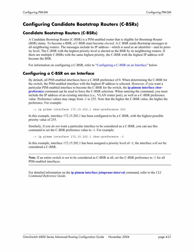
Configuring PIM-SM Configuring PIM-SM
Configuring Candidate Bootstrap Routers (C-BSRs)
Candidate Bootstrap Routers (C-BSRs)A Candidate Bootstrap Router (C-BSR) is a PIM-enabled router that is eligible for Bootstrap Router (BSR) status. To become a BSR, a C-BSR must become elected. A C-BSR sends Bootstrap messages to all neighboring routers. The messages include its IP address—which is used as an identifier—and its prior-ity level. The C-BSR with the highest priority level is elected as the BSR by its neighboring routers. If there are multiple C-BSRs with the same highest priority, the C-BSR with the highest IP address will become the BSR.
For information on configuring a C-BSR, refer to “Configuring a C-BSR on an Interface” below.
Configuring a C-BSR on an InterfaceBy default, all PIM-enabled interfaces have a C-BSR preference of 0. When determining the C-BSR for the switch, the PIM-enabled interface with the highest IP address is selected. However, if you want a particular PIM-enabled interface to become the C-BSR for the switch, the ip pimsm interface cbsr-preference command can be used to force the C-BSR selection. When entering the command, you must include the IP address of an existing interface (i.e., VLAN router port), as well as a C-BSR preference value. Preference values may range from -1 to 255. Note that the higher the C-BSR value, the higher the preference. For example:
-> ip pimsm interface 172.15.202.1 cbsr-preference 255
In this example, interface 172.15.202.1 has been configured to be a C-BSR, with the highest possible priority value of 255.
Similarly, if you do not want a particular interface to be considered as a C-BSR, you can use this command to set the C-BSR preference value to -1. For example:
-> ip pimsm interface 172.15.202.1 cbsr-preference -1
In this example, interface 172.15.202.1 has been assigned a priority level of -1; the interface will not be considered a C-BSR.
Note. If an entire switch is not to be considered as C-BSR at all, set the C-BSR preference to -1 for all PIM-enabled interfaces.
For detailed information on the ip pimsm interface joinprune-interval command, refer to the CLI Command Reference Guide.
OmniSwitch 6800 Series Advanced Routing Configuration Guide November 2004 page 4-21
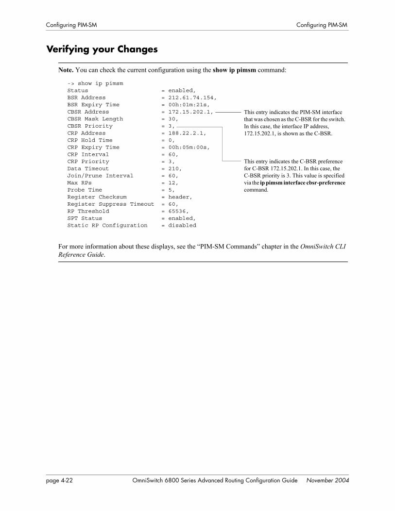
Configuring PIM-SM Configuring PIM-SM
Verifying your Changes
Note. You can check the current configuration using the show ip pimsm command:
-> show ip pimsmStatus = enabled,BSR Address = 212.61.74.154,BSR Expiry Time = 00h:01m:21s,CBSR Address = 172.15.202.1,CBSR Mask Length = 30,CBSR Priority = 3,CRP Address = 188.22.2.1,CRP Hold Time = 0,CRP Expiry Time = 00h:05m:00s,CRP Interval = 60,CRP Priority = 3,Data Timeout = 210,Join/Prune Interval = 60,Max RPs = 12,Probe Time = 5,Register Checksum = header,Register Suppress Timeout = 60,RP Threshold = 65536,SPT Status = enabled,Static RP Configuration = disabled
For more information about these displays, see the “PIM-SM Commands” chapter in the OmniSwitch CLI Reference Guide.
This entry indicates the PIM-SM interface that was chosen as the C-BSR for the switch. In this case, the interface IP address, 172.15.202.1, is shown as the C-BSR.
This entry indicates the C-BSR preference for C-BSR 172.15.202.1. In this case, the C-BSR priority is 3. This value is specified via the ip pimsm interface cbsr-preference command.
page 4-22 OmniSwitch 6800 Series Advanced Routing Configuration Guide November 2004

Configuring PIM-SM Configuring PIM-SM
Bootstrap Routers (BSRs)As described in the “PIM-SM Overview” section, the role of a Bootstrap Router (BSR) is to keep routers in the network “up to date” on reachable Candidate Rendezvous Points (C-RPs). BSRs are elected from a set of Candidate Bootstrap Routers (C-BSRs). Refer to page 4-6 for more information on C-BSRs.
Reminder. For correct operation, all PIM routers within a PIM domain must be able to map a particular multicast group address to the same Rendezvous Point (RP). PIM-SM provides two methods for group-to-RP mapping. One method is the Bootstrap Router mechanism, which also involves C-RP advertisements, as described in this section; the other method is static RP configuration. Note that, if static RP configura-tion is enabled, the Bootstrap mechanism and C-RP advertisements are automatically disabled. For more information on static RP status and configuration, refer to “Configuring Static RP Groups” below.
A C-RP periodically sends out messages, known as C-RP advertisements. When a BSR receives one of these advertisements, the associated C-RP is considered reachable (if a valid route to the network exists). The BSR then periodically sends an updated list of reachable C-RPs to all neighboring routers in the form of a Bootstrap message.
Note. The list of reachable C-RPs is also referred to as an RP set. To view the current RP set, use the show ip pimsm rp-set command. For example:
-> show ip pimsm rp-set
Group Address Address Holdtime Expires------------------+---------------+--------+-----------224.16.1.1/32 1.1.1.1 1 00h:00m:00s
For more information about these displays, see the “PIM-SM Commands” chapter in the OmniSwitch CLI Reference Guide.
Note. There is only one BSR per PIM domain. This allows all PIM routers in the PIM domain to view the same list of reachable C-RPs.
Configuring Static RP GroupsA static RP group is used in the group-to-RP mapping algorithm. To specify a static RP group, use the ip pimsm static-rp command. Be sure to enter a multicast group address, a corresponding group mask, and a 32-bit IP address for the static RP in the command line. For example:
-> ip pimsm static-rp 224.0.0.0 240.0.0.0 10.1.1.1
This command entry maps all multicast groups 224.0.0.0/4 to the static RP 10.1.1.1.
Note that, before static RP configuration changes will take effect, the global static RP status must be enabled. To enable static RP globally, use the ip pimsm static-rp status command. For example,
-> ip pimsm static-rp status enable
OmniSwitch 6800 Series Advanced Routing Configuration Guide November 2004 page 4-23

Configuring PIM-SM Configuring PIM-SM
Note. If static RP status is enabled, the method for group-to-RP mapping provided by the Bootstrap mech-anism and C-RP advertisements is automatically disabled. For more information on this alternate method of group-to-RP mapping, refer to page 4-23.
To view current Static RP Configuration settings, use the show ip pimsm static-rp command.
Group-to-RP MappingUsing one of the mechanisms described in the sections above, a PIM router receives one or more possible group-range-to-RP mappings. Each mapping specifies a range of multicast groups (expressed as a group and mask), as well as the RP to which such groups should be mapped. Each mapping may also have an associated priority. It is possible to receive multiple mappings—all of which might match the same multi-cast group. This is the common case with the BSR mechanism. The algorithm for performing the group-to-RP mapping is as follows:
1 Perform longest match on group-range to obtain a list of RPs.
2 From this list of matching RPs, find the one with the highest priority. Eliminate any RPs from the list that have lower priorities.
3 If only one RP remains in the list, use that RP.
4 If multiple RPs are in the list, use the PIM hash function defined in the RFC to choose one. The RP with the highest resulting hash value is then chosen as the RP. If more than one RP has the same highest hash value, then the RP with the highest IP address is chosen.
This algorithm is invoked by a DR when it needs to determine an RP for a given group, such as when receiving a packet or an IGMP membership indication.
page 4-24 OmniSwitch 6800 Series Advanced Routing Configuration Guide November 2004

Configuring PIM-SM Verifying the PIM-SM Configuration
Verifying the PIM-SM ConfigurationA summary of the show commands used for verifying the PIM-SM configuration is given here:
For more information about the displays that result from these commands, see the CLI Command Reference Guide.
show ip pimsm Displays global parameters for the PIM-SM domain. show ip pimsm neighbor Displays a list of active PIM-SM neighbors. show ip pimsm rp-candidate Displays the PIM-SM RP Candidate Table. show ip pimsm rp-set Displays the list of C-RPs for IP multicast groups. When the local router
is the BSR, this information is obtained from received Candidate RP Advertisements. When the local router is not the BSR, this information is obtained from received Bootstrap messages.
show ip pimsm interface Displays the current PIM-SM status for a specific interface or for all interfaces.
show ip pimsm nexthop Displays the PIM-SM Next Hop Table.show ip pimsm mroute Displays the PIM-SM Multicast Routing Table.show ip pimsm static-rp Displays the PIM Static RP table, which includes group address/mask,
the static Rendezvous Point (RP) address, and the current status of Static RP configuration (i.e., enabled or disabled).
OmniSwitch 6800 Series Advanced Routing Configuration Guide November 2004 page 4-25

PIM-SSM Support Configuring PIM-SM
PIM-SSM SupportProtocol Independent Multicast Source-Specific Multicast (PIM-SSM) is a highly-efficient extension of PIM. SSM, using an explicit channel subscription model, allows receivers to receive multicast traffic directly from the source; an RP tree model is not used. In other words, a Shortest Path Tree (SPT) between the receiver and the source is created without the use of a Rendezvous Point (RP).
By default, PIM-SM software supports Source-Specific Multicast. No additional user configuration is required. PIM-SSM is automatically enabled and operational as long as PIM-SM is loaded (see page 4-4) and IGMPv3 source-specific joins are received within the SSM address range.
For detailed information on PIM-SSM and Source-Specific Multicast, refer to the IETF Internet Drafts draft-ietf-pim-sm-v2-new-05.txt and draft-ietf-ssm-arch-04.txt, as well as RFC 3569, “An Overview of Source-Specific Multicast (SSM).”
Note. For networks using IGMP proxy, be sure that the IGMP proxy version is set to Version 3. Otherwise, PIM-SSM will not function. For information on configuring the IGMP proxy version, refer to the ip multicast igmp-proxy-version command.
Source-Specific Multicast AddressesMulticast addresses 232.0.0.0 through 232.255.255.255 have been reserved by the Internet Assigned Numbers Authority (IANA) as Source-Specific Multicast (SSM) destination addresses. Addresses within this range are reserved for use by source-specific applications and protocols (e.g., PIM-SSM) and cannot be used for any other functions or protocols.
PIM-SSM Specifications
RFCs Supported 3569—An Overview of Source-Specific Multicast (SSM)
Internet Drafts Supported draft-ietf-pim-sm-v2-new-05.txt—Protocol Independent Multicast – Sparse Mode (PIM-SM)
draft-ietf-ssm-arch-04.txt—An Overview of Source-Specific Multicast (SSM)
Valid SSM Address Range 232.0.0.0 to 232.255.255.255
page 4-26 OmniSwitch 6800 Series Advanced Routing Configuration Guide November 2004

A Software License andCopyright Statements
This appendix contains Alcatel and third-party software vendor license and copyright statements.
Alcatel License Agreement
ALCATEL INTERNETWORKING, INC. (“AII”) SOFTWARE LICENSE AGREEMENT
IMPORTANT. Please read the terms and conditions of this license agreement carefully before opening this package.
By opening this package, you accept and agree to the terms of this license agreement. If you are not willing to be bound by the terms of this license agreement, do not open this package. Please promptly return the product and any materials in unopened form to the place where you obtained it for a full refund.
1. License Grant. This is a license, not a sales agreement, between you (the “Licensee”) and AII. AII hereby grants to Licensee, and Licensee accepts, a non-exclusive license to use program media and computer software contained therein (the “Licensed Files”) and the accompanying user documentation (collectively the “Licensed Materials”), only as authorized in this License Agreement. Licensee, subject to the terms of this License Agreement, may use one copy of the Licensed Files on the Licensee’s system. Licensee agrees not to assign, sublicense, transfer, pledge, lease, rent, or share their rights under this License Agreement. Licensee may retain the program media for backup purposes with retention of the copyright and other proprietary notices. Except as authorized under this paragraph, no copies of the Licensed Materials or any portions thereof may be made by Licensee and Licensee shall not modify, decompile, disassemble, reverse engineer, or otherwise attempt to derive the Source Code. Licensee is also advised that AII products contain embedded software known as firmware which resides in silicon. Licensee may not copy the firmware or transfer the firmware to another medium.
2. AII’s Rights. Licensee acknowledges and agrees that the Licensed Materials are the sole property of AII and its licensors (herein “its licensors”), protected by U.S. copyright law, trademark law, and are licensed on a right to use basis. Licensee further acknowledges and agrees that all rights, title, and interest in and to the Licensed Materials are and shall remain with AII and its licensors and that no such right, license, or interest shall be asserted with respect to such copyrights and trademarks. This License Agree-ment does not convey to Licensee an interest in or to the Licensed Materials, but only a limited right to use revocable in accordance with the terms of this License Agreement.
OmniSwitch 6800 Series Advanced Routing Configuration Guide November 2004 page A-1

Alcatel License Agreement Software License and Copyright Statements
3. Confidentiality. AII considers the Licensed Files to contain valuable trade secrets of AII, the unautho-rized disclosure of which could cause irreparable harm to AII. Except as expressly set forth herein, Licensee agrees to use reasonable efforts not to disclose the Licensed Files to any third party and not to use the Licensed Files other than for the purpose authorized by this License Agreement. This confidential-ity obligation shall continue after any termination of this License Agreement.
4. Indemnity. Licensee agrees to indemnify, defend and hold AII harmless from any claim, lawsuit, legal proceeding, settlement or judgment (including without limitation AII’s reasonable United States and local attorneys’ and expert witnesses’ fees and costs) arising out of or in connection with the unauthorized copy-ing, marketing, performance or distribution of the Licensed Files.
5. Limited Warranty. AII warrants, for Licensee’s benefit alone, that the program media shall, for a period of ninety (90) days from the date of commencement of this License Agreement (referred to as the Warranty Period), be free from defects in material and workmanship. AII further warrants, for Licensee benefit alone, that during the Warranty Period the Licensed Files shall operate substantially in accordance with the functional specifications in the User Guide. If during the Warranty Period, a defect in the Licensed Files appears, Licensee may return the Licensed Files to AII for either replacement or, if so elected by AII, refund of amounts paid by Licensee under this License Agreement. EXCEPT FOR THE WARRANTIES SET FORTH ABOVE, THE LICENSED MATERIALS ARE LICENSED “AS IS” AND AII AND ITS LICENSORS DISCLAIM ANY AND ALL OTHER WARRANTIES, WHETHER EXPRESS OR IMPLIED, INCLUDING (WITHOUT LIMITATION) ANY IMPLIED WARRANTIES OF MERCHANTABILITY OR FITNESS FOR A PARTICULAR PURPOSE. SOME STATES DO NOT ALLOW THE EXCLUSION OF IMPLIED WARRANTIES SO THE ABOVE EXCLUSIONS MAY NOT APPLY TO LICENSEE. THIS WARRANTY GIVES THE LICENSEE SPECIFIC LEGAL RIGHTS. LICENSEE MAY ALSO HAVE OTHER RIGHTS WHICH VARY FROM STATE TO STATE.
6. Limitation of Liability. AII’s cumulative liability to Licensee or any other party for any loss or damages resulting from any claims, demands, or actions arising out of or relating to this License Agree-ment shall not exceed the license fee paid to AII for the Licensed Materials. IN NO EVENT SHALL AII BE LIABLE FOR ANY INDIRECT, INCIDENTAL, CONSEQUENTIAL, SPECIAL, OR EXEM-PLARY DAMAGES OR LOST PROFITS, EVEN IF AII HAS BEEN ADVISED OF THE POSSIBIL-ITY OF SUCH DAMAGES. SOME STATES DO NOT ALLOW THE LIMITATION OR EXCLUSION OF LIABILITY FOR INCIDENTAL OR CONSEQUENTIAL DAMAGES, SO THE ABOVE LIMITA-TION OR EXCLUSION TO INCIDENTAL OR CONSEQUENTIAL DAMAGES MAY NOT APPLY TO LICENSEE.
7. Export Control. This product is subject to the jurisdiction of the United States. Licensee may not export or reexport the Licensed Files, without complying with all United States export laws and regula-tions, including but not limited to (i) obtaining prior authorization from the U.S. Department of Commerce if a validated export license is required, and (ii) obtaining “written assurances” from licensees, if required.
8. Support and Maintenance. Except as may be provided in a separate agreement between AII and Licensee, if any, AII is under no obligation to maintain or support the copies of the Licensed Files made and distributed hereunder and AII has no obligation to furnish Licensee with any further assistance, docu-mentation or information of any nature or kind.
9. Term. This License Agreement is effective upon Licensee opening this package and shall continue until terminated. Licensee may terminate this License Agreement at any time by returning the Licensed Materi-als and all copies thereof and extracts therefrom to AII and certifying to AII in writing that all Licensed Materials and all copies thereof and extracts therefrom have been returned or erased by the memory of Licensee’s computer or made non-readable. AII may terminate this License Agreement upon the breach by Licensee of any term hereof. Upon such termination by AII, Licensee agrees to return to AII or destroy the Licensed Materials and all copies and portions thereof.
page A-2 OmniSwitch 6800 Series Advanced Routing Configuration Guide November 2004

Software License and Copyright Statements Alcatel License Agreement
10. Governing Law. This License Agreement shall be construed and governed in accordance with the laws of the State of California.
11. Severability. Should any term of this License Agreement be declared void or unenforceable by any court of competent jurisdiction, such declaration shall have no effect on the remaining terms herein.
12. No Waiver. The failure of either party to enforce any rights granted hereunder or to take action against the other party in the event of any breach hereunder shall not be deemed a waiver by that party as to subsequent enforcement of rights or subsequent actions in the event of future breaches.
13. Notes to United States Government Users. Software and documentation are provided with restricted rights. Use, duplication or disclosure by the government is subject to (i) restrictions set forth in GSA ADP Schedule Contract with AII’s reseller(s), or (ii) restrictions set forth in subparagraph (c) (1) and (2) of 48 CFR 52.227-19, as applicable.
14.Third Party Materials. Licensee is notified that the Licensed Files contain third party software and materials licensed to AII by certain third party licensors. Some third party licensors (e.g., Wind River and their licensors with respect to the Run-Time Module) are third part beneficiaries to this License Agree-ment with full rights of enforcement. Please refer to the section entitled “Third Party Licenses and Notices” on page A-4 for the third party license and notice terms.
OmniSwitch 6800 Series Advanced Routing Configuration Guide November 2004 page A-3

Third Party Licenses and Notices Software License and Copyright Statements
Third Party Licenses and NoticesThe licenses and notices related only to such third party software are set forth below:
A.Booting and Debugging Non-Proprietary SoftwareA small, separate software portion aggregated with the core software in this product and primarily used for initial booting and debugging constitutes non-proprietary software, some of which may be obtained in source code format from AII for a limited period of time. AII will provide a machine-readable copy of the applicable non-proprietary software to any requester for a cost of copying, shipping and handling. This offer will expire 3 years from the date of the first shipment of this product.
B. The OpenLDAP Public License: Version 2.4, 8 December 2000Redistribution and use of this software and associated documentation (“Software”), with or without modi-fication, are permitted provided that the following conditions are met:
1 Redistributions of source code must retain copyright statements and notices.
2 Redistributions in binary form must reproduce applicable copyright statements and notices, this list of conditions, and the following disclaimer in the documentation and/or other materials provided with the distribution.
3 Redistributions must contain a verbatim copy of this document.
4 The names and trademarks of the authors and copyright holders must not be used in advertising or otherwise to promote the sale, use or other dealing in this Software without specific, written prior permis-sion.
5 Due credit should be given to the OpenLDAP Project.
6 The OpenLDAP Foundation may revise this license from time to time. Each revision is distinguished by a version number. You may use the Software under terms of this license revision or under the terms of any subsequent revision of the license.
THIS SOFTWARE IS PROVIDED BY THE OPENLDAP FOUNDATION AND CONTRIBUTORS “AS IS” AND ANY EXPRESSED OR IMPLIED WARRANTIES, INCLUDING, BUT NOT LIMITED TO, THE IMPLIED WARRANTIES OF MERCHANTABILITY AND FITNESS FOR A PARTICULAR PURPOSE ARE DISCLAIMED. IN NO EVENT SHALL THE OPENLDAP FOUNDATION OR ITS CONTRIBUTORS BE LIABLE FOR ANY DIRECT, INDIRECT, INCIDENTAL, SPECIAL, EXEM-PLARY, OR CONSEQUENTIAL DAMAGES (INCLUDING, BUT NOT LIMITED TO, PROCURE-MENT OF SUBSTITUTE GOODS OR SERVICES; LOSS OF USE, DATA, OR PROFITS; OR BUSINESS INTERRUPTION) HOWEVER CAUSED AND ON ANY THEORY OF LIABILITY, WHETHER IN CONTRACT, STRICT LIABILITY, OR TORT (INCLUDING NEGLIGENCE OR OTHERWISE) ARISING IN ANY WAY OUT OF THE USE OF THIS SOFTWARE, EVEN IF ADVISED OF THE POSSIBILITY OF SUCH DAMAGE.
OpenLDAP is a trademark of the OpenLDAP Foundation.
Copyright 1999-2000 The OpenLDAP Foundation, Redwood City, California, USA. All Rights Reserved. Permission to copy and distributed verbatim copies of this document is granted.
page A-4 OmniSwitch 6800 Series Advanced Routing Configuration Guide November 2004

Software License and Copyright Statements Third Party Licenses and Notices
C. LinuxLinux is written and distributed under the GNU General Public License which means that its source code is freely-distributed and available to the general public.
D. GNU GENERAL PUBLIC LICENSE: Version 2, June 1991 Copyright (C) 1989, 1991 Free Software Foundation, Inc. 675 Mass Ave, Cambridge, MA 02139, USA Everyone is permitted to copy and distribute verbatim copies of this license document, but changing it is not allowed.
Preamble
The licenses for most software are designed to take away your freedom to share and change it. By contrast, the GNU General Public License is intended to guarantee your freedom to share and change free software--to make sure the software is free for all its users. This General Public License applies to most of the Free Software Foundation’s software and to any other program whose authors commit to using it. (Some other Free Software Foundation software is covered by the GNU Library General Public License instead.) You can apply it to your programs, too.
When we speak of free software, we are referring to freedom, not price. Our General Public Licenses are designed to make sure that you have the freedom to distribute copies of free software (and charge for this service if you wish), that you receive source code or can get it if you want it, that you can change the soft-ware or use pieces of it in new free programs; and that you know you can do these things.
To protect your rights, we need to make restrictions that forbid anyone to deny you these rights or to ask you to surrender the rights. These restrictions translate to certain responsibilities for you if you distribute copies of the software, or if you modify it.
For example, if you distribute copies of such a program, whether gratis or for a fee, you must give the recipients all the rights that you have. You must make sure that they, too, receive or can get the source code. And you must show them these terms so they know their rights.
We protect your rights with two steps: (1) copyright the software, and (2) offer you this license which gives you legal permission to copy, distribute and/or modify the software.
Also, for each author’s protection and ours, we want to make certain that everyone understands that there is no warranty for this free software. If the software is modified by someone else and passed on, we want its recipients to know that what they have is not the original, so that any problems introduced by others will not reflect on the original authors’ reputations.
Finally, any free program is threatened constantly by software patents. We wish to avoid the danger that redistributors of a free program will individually obtain patent licenses, in effect making the program proprietary. To prevent this, we have made it clear that any patent must be licensed for everyone’s free use or not licensed at all.
The precise terms and conditions for copying, distribution and modification follow.
GNU GENERAL PUBLIC LICENSE TERMS AND CONDITIONS FOR COPYING, DISTRIBUTION AND MODIFICATION
0 This License applies to any program or other work which contains a notice placed by the copyright holder saying it may be distributed under the terms of this General Public License. The “Program”, below, refers to any such program or work, and a “work based on the Program” means either the Program or any derivative work under copyright law: that is to say, a work containing the Program or a portion of it, either
OmniSwitch 6800 Series Advanced Routing Configuration Guide November 2004 page A-5

Third Party Licenses and Notices Software License and Copyright Statements
verbatim or with modifications and/or translated into another language. (Hereinafter, translation is included without limitation in the term “modification”.) Each licensee is addressed as “you”.
Activities other than copying, distribution and modification are not covered by this License; they are outside its scope. The act of running the Program is not restricted, and the output from the Program is covered only if its contents constitute a work based on the Program (independent of having been made by running the Program). Whether that is true depends on what the Program does.
1 You may copy and distribute verbatim copies of the Program’s source code as you receive it, in any medium, provided that you conspicuously and appropriately publish on each copy an appropriate copy-right notice and disclaimer of warranty; keep intact all the notices that refer to this License and to the absence of any warranty; and give any other recipients of the Program a copy of this License along with the Program.
You may charge a fee for the physical act of transferring a copy, and you may at your option offer warranty protection in exchange for a fee.
2 You may modify your copy or copies of the Program or any portion of it, thus forming a work based on the Program, and copy and distribute such modifications or work under the terms of Section 1 above, provided that you also meet all of these conditions:
a You must cause the modified files to carry prominent notices stating that you changed the files and the date of any change.
b You must cause any work that you distribute or publish, that in whole or in part contains or is derived from the Program or any part thereof, to be licensed as a whole at no charge to all third parties under the terms of this License.
c If the modified program normally reads commands interactively when run, you must cause it, when started running for such interactive use in the most ordinary way, to print or display an announcement including an appropriate copyright notice and a notice that there is no warranty (or else, saying that you provide a warranty) and that users may redistribute the program under these conditions, and telling the user how to view a copy of this License. (Exception: if the Program itself is interactive but does not normally print such an announcement, your work based on the Program is not required to print an announcement.)
These requirements apply to the modified work as a whole. If identifiable sections of that work are not derived from the Program, and can be reasonably considered independent and separate works in them-selves, then this License, and its terms, do not apply to those sections when you distribute them as sepa-rate works. But when you distribute the same sections as part of a whole which is a work based on the Program, the distribution of the whole must be on the terms of this License, whose permissions for other licensees extend to the entire whole, and thus to each and every part regardless of who wrote it. Thus, it is not the intent of this section to claim rights or contest your rights to work written entirely by you; rather, the intent is to exercise the right to control the distribution of derivative or collective works based on the Program.
In addition, mere aggregation of another work not based on the Program with the Program (or with a work based on the Program) on a volume of a storage or distribution medium does not bring the other work under the scope of this License.
3 You may copy and distribute the Program (or a work based on it, under Section 2) in object code or executable form under the terms of Sections 1 and 2 above provided that you also do one of the following:
a Accompany it with the complete corresponding machine-readable source code, which must be distributed under the terms of Sections 1 and 2 above on a medium customarily used for software inter-change; or,
page A-6 OmniSwitch 6800 Series Advanced Routing Configuration Guide November 2004

Software License and Copyright Statements Third Party Licenses and Notices
b Accompany it with a written offer, valid for at least three years, to give any third party, for a charge no more than your cost of physically performing source distribution, a complete machine-readable copy of the corresponding source code, to be distributed under the terms of Sections 1 and 2 above on a medium customarily used for software interchange; or,
c Accompany it with the information you received as to the offer to distribute corresponding source code. (This alternative is allowed only for noncommercial distribution and only if you received the program in object code or executable form with such an offer, in accord with Subsection b above.)
The source code for a work means the preferred form of the work for making modifications to it. For an executable work, complete source code means all the source code for all modules it contains, plus any associated interface definition files, plus the scripts used to control compilation and installation of the executable. However, as a special exception, the source code distributed need not include anything that is normally distributed (in either source or binary form) with the major components (compiler, kernel, and so on) of the operating system on which the executable runs, unless that component itself accompanies the executable.
If distribution of executable or object code is made by offering access to copy from a designated place, then offering equivalent access to copy the source code from the same place counts as distribution of the source code, even though third parties are not compelled to copy the source along with the object code.
4 You may not copy, modify, sublicense, or distribute the Program except as expressly provided under this License. Any attempt otherwise to copy, modify, sublicense or distribute the Program is void, and will automatically terminate your rights under this License. However, parties who have received copies, or rights, from you under this License will not have their licenses terminated so long as such parties remain in full compliance.
5 You are not required to accept this License, since you have not signed it. However, nothing else grants you permission to modify or distribute the Program or its derivative works. These actions are prohibited by law if you do not accept this License. Therefore, by modifying or distributing the Program (or any work based on the Program), you indicate your acceptance of this License to do so, and all its terms and conditions for copying, distributing or modifying the Program or works based on it.
6 Each time you redistribute the Program (or any work based on the Program), the recipient automati-cally receives a license from the original licensor to copy, distribute or modify the Program subject to these terms and conditions. You may not impose any further restrictions on the recipients’ exercise of the rights granted herein. You are not responsible for enforcing compliance by third parties to this License.
7 If, as a consequence of a court judgment or allegation of patent infringement or for any other reason (not limited to patent issues), conditions are imposed on you (whether by court order, agreement or other-wise) that contradict the conditions of this License, they do not excuse you from the conditions of this License. If you cannot distribute so as to satisfy simultaneously your obligations under this License and any other pertinent obligations, then as a consequence you may not distribute the Program at all. For example, if a patent license would not permit royalty-free redistribution of the Program by all those who receive copies directly or indirectly through you, then the only way you could satisfy both it and this License would be to refrain entirely from distribution of the Program.
If any portion of this section is held invalid or unenforceable under any particular circumstance, the balance of the section is intended to apply and the section as a whole is intended to apply in other circum-stances.
It is not the purpose of this section to induce you to infringe any patents or other property right claims or to contest validity of any such claims; this section has the sole purpose of protecting the integrity of the free software distribution system, which is implemented by public license practices. Many people have made generous contributions to the wide range of software distributed through that system in reliance on
OmniSwitch 6800 Series Advanced Routing Configuration Guide November 2004 page A-7

Third Party Licenses and Notices Software License and Copyright Statements
consistent application of that system; it is up to the author/donor to decide if he or she is willing to distrib-ute software through any other system and a licensee cannot impose that choice.
This section is intended to make thoroughly clear what is believed to be a consequence of the rest of this License.
8 If the distribution and/or use of the Program is restricted in certain countries either by patents or by copyrighted interfaces, the original copyright holder who places the Program under this License may add an explicit geographical distribution limitation excluding those countries, so that distribution is permitted only in or among countries not thus excluded. In such case, this License incorporates the limitation as if written in the body of this License.
9 The Free Software Foundation may publish revised and/or new versions of the General Public License from time to time. Such new versions will be similar in spirit to the present version, but may differ in detail to address new problems or concerns.
Each version is given a distinguishing version number. If the Program specifies a version number of this License which applies to it and “any later version”, you have the option of following the terms and condi-tions either of that version or of any later version published by the Free Software Foundation. If the Program does not specify a version number of this License, you may choose any version ever published by the Free Software Foundation.
10 If you wish to incorporate parts of the Program into other free programs whose distribution conditions are different, write to the author to ask for permission. For software which is copyrighted by the Free Soft-ware Foundation, write to the Free Software Foundation; we sometimes make exceptions for this. Our decision will be guided by the two goals of preserving the free status of all derivatives of our free soft-ware and of promoting the sharing and reuse of software generally.
NO WARRANTY
11 BECAUSE THE PROGRAM IS LICENSED FREE OF CHARGE, THERE IS NO WARRANTY FOR THE PROGRAM, TO THE EXTENT PERMITTED BY APPLICABLE LAW. EXCEPT WHEN OTHERWISE STATED IN WRITING THE COPYRIGHT HOLDERS AND/OR OTHER PARTIES PROVIDE THE PROGRAM “AS IS” WITHOUT WARRANTY OF ANY KIND, EITHER EXPRESSED OR IMPLIED, INCLUDING, BUT NOT LIMITED TO, THE IMPLIED WARRANTIES OF MERCHANTABILITY AND FITNESS FOR A PARTICULAR PURPOSE. THE ENTIRE RISK AS TO THE QUALITY AND PERFORMANCE OF THE PROGRAM IS WITH YOU. SHOULD THE PROGRAM PROVE DEFECTIVE, YOU ASSUME THE COST OF ALL NECESSARY SERVICING, REPAIR OR CORRECTION.
12 IN NO EVENT UNLESS REQUIRED BY APPLICABLE LAW OR AGREED TO IN WRITING WILL ANY COPYRIGHT HOLDER, OR ANY OTHER PARTY WHO MAY MODIFY AND/OR REDISTRIBUTE THE PROGRAM AS PERMITTED ABOVE, BE LIABLE TO YOU FOR DAMAGES, INCLUDING ANY GENERAL, SPECIAL, INCIDENTAL OR CONSEQUENTIAL DAMAGES ARIS-ING OUT OF THE USE OR INABILITY TO USE THE PROGRAM (INCLUDING BUT NOT LIMITED TO LOSS OF DATA OR DATA BEING RENDERED INACCURATE OR LOSSES SUSTAINED BY YOU OR THIRD PARTIES OR A FAILURE OF THE PROGRAM TO OPERATE WITH ANY OTHER PROGRAMS), EVEN IF SUCH HOLDER OR OTHER PARTY HAS BEEN ADVISED OF THE POSSIBILITY OF SUCH DAMAGES.
END OF TERMS AND CONDITIONS
page A-8 OmniSwitch 6800 Series Advanced Routing Configuration Guide November 2004
Software License and Copyright Statements Third Party Licenses and Notices
Appendix: How to Apply These Terms to Your New Programs
If you develop a new program, and you want it to be of the greatest possible use to the public, the best way to achieve this is to make it free software which everyone can redistribute and change under these terms.
To do so, attach the following notices to the program. It is safest to attach them to the start of each source file to most effectively convey the exclusion of warranty; and each file should have at least the “copy-right” line and a pointer to where the full notice is found.
<one line to give the program’s name and a brief idea of what it does.> Copyright (C)19yy <name of author>
This program is free software; you can redistribute it and/or modify it under the terms ofthe GNU General Public License as published by the Free Software Foundation; eitherversion 2 of the License, or (at your option) any later version.
This program is distributed in the hope that it will be useful, but WITHOUT ANYWARRANTY; without even the implied warranty of MERCHANTABILITY orFITNESS FOR A PARTICULAR PURPOSE. See the GNU General Public Licensefor more details.
You should have received a copy of the GNU General Public License along with thisprogram; if not, write to the Free Software Foundation, Inc., 675 Mass Ave, Cambridge,MA 02139, USA.
Also add information on how to contact you by electronic and paper mail.
If the program is interactive, make it output a short notice like this when it starts in an interactive mode:
Gnomovision version 69, Copyright (C) 19yy name of author Gnomovision comes with ABSOLUTELY NO WARRANTY; for details type ‘show w’. This is free software, and you are welcome to redistribute it under certain conditions; type ‘show c’ for details.
The hypothetical commands ‘show w’ and ‘show c’ should show the appropriate parts of the General Public License. Of course, the commands you use may be called something other than ‘show w’ and ‘show c’; they could even be mouse-clicks or menu items--whatever suits your program.
You should also get your employer (if you work as a programmer) or your school, if any, to sign a “copy-right disclaimer” for the program, if necessary. Here is a sample; alter the names:
Yoyodyne, Inc., hereby disclaims all copyright interest in the program ‘Gnomovision’ (which makes passes at compilers) written by James Hacker.
<signature of Ty Coon>, 1 April 1989 Ty Coon, President of Vice
This General Public License does not permit incorporating your program into proprietary programs. If your program is a subroutine library, you may consider it more useful to permit linking proprietary appli-cations with the library. If this is what you want to do, use the GNU Library General Public License instead of this License.
URLWatch:For notice when this page changes, fill in your email address.
Maintained by: Webmaster, Linux Online Inc. Last modified: 09-Aug-2000 02:03AM. Views since 16-Aug-2000: 177203.
OmniSwitch 6800 Series Advanced Routing Configuration Guide November 2004 page A-9

Third Party Licenses and Notices Software License and Copyright Statements
Material copyright Linux Online Inc. Design and compilation copyright (c)1994-2002 Linux Online Inc. Linux is a registered trademark of Linus Torvalds Tux the Penguin, featured in our logo, was created by Larry Ewing Consult our privacy statement
URLWatch provided by URLWatch Services. All rights reserved.
E. University of California Provided with this product is certain TCP input and Telnet client software developed by the University of California, Berkeley.
F. Carnegie-Mellon University Provided with this product is certain BOOTP Relay software developed by Carnegie-Mellon University.
G.Random.cPR 30872 B Kesner created May 5 2000PR 30872 B Kesner June 16 2000 moved batch_entropy_process to own task iWhirlpool to make code more efficient
random.c -- A strong random number generator
Version 1.89, last modified 19-Sep-99
Copyright Theodore Ts’o, 1994, 1995, 1996, 1997, 1998, 1999. All rights reserved.
Redistribution and use in source and binary forms, with or without modification, are permitted provided that the following conditions are met:
1. Redistributions of source code must retain the above copyright notice, and the entire permission notice in its entirety, including the disclaimer of warranties.
2. Redistributions in binary form must reproduce the above copyright notice, this list of conditions and the following disclaimer in the documentation and/or other materials provided with the distribution.
3. The name of the author may not be used to endorse or promote products derived from this software without specific prior written permission. ALTERNATIVELY, this product may be distributed under the terms of the GNU Public License, in which case the provisions of the GPL are required INSTEAD OF the above restrictions. (This clause is necessary due to a potential bad interaction between the GPL and the restrictions contained in a BSD-style copyright.)
THIS SOFTWARE IS PROVIDED “AS IS” AND ANY EXPRESS OR IMPLIED WARRANTIES, INCLUDING, BUT NOT LIMITED TO, THE IMPLIED WARRANTIES OF MERCHANTABILITY AND FITNESS FOR A PARTICULAR PURPOSE, ALL OF WHICH ARE HEREBY DISCLAIMED. IN NO EVENT SHALL THE AUTHOR BE LIABLE FOR ANY DIRECT, INDIRECT, INCIDENTAL, SPECIAL, EXEMPLARY, OR CONSEQUENTIAL DAMAGES (INCLUDING, BUT NOT LIMITED TO, PROCUREMENT OF SUBSTITUTE GOODS OR SERVICES; LOSS OF USE, DATA, OR PROF-ITS; OR BUSINESS INTERRUPTION) HOWEVER CAUSED AND ON ANY THEORY OF LIABIL-ITY, WHETHER IN CONTRACT, STRICT LIABILITY, OR TORT (INCLUDING NEGLIGENCE OR OTHERWISE) ARISING IN ANY WAY OUT OF THE USE OF THIS SOFTWARE, EVEN IF NOT ADVISED OF THE POSSIBILITY OF SUCH DAMAGE.
page A-10 OmniSwitch 6800 Series Advanced Routing Configuration Guide November 2004

Software License and Copyright Statements Third Party Licenses and Notices
H.Apptitude, Inc.Provided with this product is certain network monitoring software (“MeterWorks/RMON”) licensed from Apptitude, Inc., whose copyright notice is as follows: Copyright (C) 1997-1999 by Apptitude, Inc. All Rights Reserved. Licensee is notified that Apptitude, Inc. (formerly, Technically Elite, Inc.), a California corporation with principal offices at 6330 San Ignacio Avenue, San Jose, California, is a third party bene-ficiary to the Software License Agreement. The provisions of the Software License Agreement as applied to MeterWorks/RMON are made expressly for the benefit of Apptitude, Inc., and are enforceable by Apptitude, Inc. in addition to AII. IN NO EVENT SHALL APPTITUDE, INC. OR ITS SUPPLIERS BE LIABLE FOR ANY DAMAGES, INCLUDING COSTS OF PROCUREMENT OF SUBSTITUTE PRODUCTS OR SERVICES, LOST PROFITS, OR ANY SPECIAL, INDIRECT, CONSEQUENTIAL OR INCIDENTAL DAMAGES, HOWEVER CAUSED AND ON ANY THEORY OF LIABILITY, ARISING IN ANY WAY OUT OF THIS AGREEMENT.
I. AgranatProvided with this product is certain web server software (“EMWEB PRODUCT”) licensed from Agranat Systems, Inc. (“Agranat”). Agranat has granted to AII certain warranties of performance, which warran-ties [or portion thereof] AII now extends to Licensee. IN NO EVENT, HOWEVER, SHALL AGRANAT BE LIABLE TO LICENSEE FOR ANY INDIRECT, SPECIAL, OR CONSEQUENTIAL DAMAGES OF LICENSEE OR A THIRD PARTY AGAINST LICENSEE ARISING OUT OF, OR IN CONNEC-TION WITH, THIS DISTRIBUTION OF EMWEB PRODUCT TO LICENSEE. In case of any termina-tion of the Software License Agreement between AII and Licensee, Licensee shall immediately return the EMWEB Product and any back-up copy to AII, and will certify to AII in writing that all EMWEB Prod-uct components and any copies of the software have been returned or erased by the memory of Licensee’s computer or made non-readable.
J. RSA Security Inc.Provided with this product is certain security software (“RSA Software”) licensed from RSA Security Inc. RSA SECURITY INC. PROVIDES RSA SOFTWARE “AS IS” WITHOUT ANY WARRANTY WHAT-SOEVER. RSA SECURITY INC. DISCLAIMS ALL WARRANTIES, EXPRESS, IMPLIED OR STAT-UTORY, AS TO ANY MATTER WHATSOEVER INCLUDING ALL IMPLIED WARRANTIES OF MERCHANTABILITY, FITNESS FOR A PARTICULAR PURPOSE AND NON-INFRINGEMENT OF THIRD PARTY RIGHTS.
K. Sun Microsystems, Inc.This product contains Coronado ASIC, which includes a component derived from designs licensed from Sun Microsystems, Inc.
OmniSwitch 6800 Series Advanced Routing Configuration Guide November 2004 page A-11

Third Party Licenses and Notices Software License and Copyright Statements
L. Wind River Systems, Inc.Provided with this product is certain software (“Run-Time Module”) licensed from Wind River Systems, Inc. Licensee is prohibited from: (i) copying the Run-Time Module, except for archive purposes consis-tent with Licensee’s archive procedures; (ii) transferring the Run-Time Module to a third party apart from the product; (iii) modifying, decompiling, disassembling, reverse engineering or otherwise attempting to derive the source code of the Run-Time Module; (iv) exporting the Run-Time Module or underlying tech-nology in contravention of applicable U.S. and foreign export laws and regulations; and (v) using the Run-Time Module other than in connection with operation of the product. In addition, please be advised that: (i) the Run-Time Module is licensed, not sold and that AII and its licensors retain ownership of all copies of the Run-Time Module; (ii) WIND RIVER DISCLAIMS ALL IMPLIED WARRANTIES, INCLUD-ING WITHOUT LIMITATION THE IMPLIED WARRANTIES OF MERCHANTABILITY, FITNESS FOR A PARTICULAR PURPOSE, (iii) The SOFTWARE LICENSE AGREEMENT EXCLUDES LIABILITY FOR ANY SPECIAL, INDIRECT, PUNITIVE, INCIDENTAL AND CONSEQUENTIAL DAMAGES; and (iv) any further distribution of the Run-Time Module shall be subject to the same restric-tions set forth herein. With respect to the Run-Time Module, Wind River and its licensors are third party beneficiaries of the License Agreement and the provisions related to the Run-Time Module are made expressly for the benefit of, and are enforceable by, Wind River and its licensors.
M.Network Time Protocol Version 4The following copyright notice applies to all files collectively called the Network Time Protocol Version 4 Distribution. Unless specifically declared otherwise in an individual file, this notice applies as if the text was explicitly included in the file.
************************************************************************ ** Copyright (c) David L. Mills 1992-2003 ** ** Permission to use, copy, modify, and distribute this software and ** its documentation for any purpose and without fee is hereby ** granted, provided that the above copyright notice appears in all ** copies and that both the copyright notice and this permission ** notice appear in supporting documentation, and that the name ** University of Delaware not be used in advertising or publicity ** pertaining to distribution of the software without specific, ** written prior permission. The University of Delaware makes no ** representations about the suitability this software for any ** purpose. It is provided "as is" without express or implied ** warranty. ** **************************************************************************
page A-12 OmniSwitch 6800 Series Advanced Routing Configuration Guide November 2004

Index
Aapplication examples
DVMRP 3-3multicast address boundaries 2-2, 2-8OSPF 1-4, 1-30PIM-SM 4-4
area border routers 1-8, 1-9areas 1-8
assigning interfaces 1-20backbones 1-8border routers 1-8creating 1-17deleting 1-18enabling 1-17NSSAs 1-11ranges 1-19route metrics 1-19specifying type 1-17status 1-18stub 1-10summarization 1-18
ASboundary routers 1-9
ASBRs 1-24authentication 1-21
MD5 encryption 1-21simple 1-21
Autonomous System Boundary Routersee ASBRs
autonomous systemssee AS
Bbackbone routers 1-9backbones 1-8Bootstrap Router
see BSRboundary routers 1-9BSR 4-6, 4-23
CCandidate Bootstrap Router
see C-BSRCandidate Rendezvous Point
see C-RP routerC-BSR 4-6, 4-21C-RP router 4-5, 4-18
Ddefaults
DVMRP 3-2OSPF 1-3PIM-SM 4-3
Designated Routersee DR
Distance Vector Multicast Routing Protocolsee DVMRP
DR 4-6DVMRP 3-1
application examples 3-3automatic loading and enabling 3-13configuring 3-10defaults 3-2dependent downstream routers 3-7enabling 3-10graft acknowledgment messages 3-8graft messages 3-8grafting 3-8, 3-17hop count 3-7IGMP 3-5interface metric 3-7metrics 3-7multicast source location 3-7neighbor communications 3-13neighbor discovery 3-6overview 3-5poison reverse 3-7probe messages 3-6prune messages 3-8pruning 3-8, 3-15reverse path forwarding check 3-7reverse path multicasting 3-5route report messages 3-6, 3-7, 3-14routes 3-14tunnels 3-9, 3-17verifying the configuration 3-17
dynamic routingDVMRP 3-1multicast address boundaries 2-1PIM-SM 4-1
EECMP routing 1-11
IIGMP
DVMRP 3-5interior gateway protocols
OSPF 1-7internal routers 1-9ip dvmrp flash-interval command 3-14ip dvmrp graft-timeout command 3-8ip dvmrp interface command 3-11ip dvmrp interface metric command 3-11ip dvmrp neighbor-interval command 3-13
OmniSwitch 6800 Series Advanced Routing Configuration Guide November 2004 Index-1

Index
ip dvmrp neighbor-timeout command 3-13ip dvmrp prune-lifetime command 3-15ip dvmrp prune-timeout command 3-15ip dvmrp report-interval command 3-14ip dvmrp route-holddown command 3-14ip dvmrp route-timeout command 3-14ip dvmrp status command 3-12ip load dvmrp command 3-10ip load ospf command 1-16ip load pimsm command 4-15ip mroute-boundary command 2-2, 2-7ip multicast switching command 3-3, 4-4, 4-15ip ospf area command 1-17ip ospf area status command 1-17ip ospf area summary command 1-18ip ospf area type command 1-17ip ospf asbr command 1-24ip ospf exit-overflow-interval command 1-27ip ospf extlsdb-limit command 1-27ip ospf host command 1-27ip ospf interface area command 1-20ip ospf interface auth-key command 1-21ip ospf interface auth-type command 1-21ip ospf interface command 1-20ip ospf interface cost command 1-22ip ospf interface dead-interval command 1-22ip ospf interface hello-interval command 1-22ip ospf interface md5 command 1-21ip ospf interface poll-interval command 1-22ip ospf interface priority command 1-22ip ospf interface retrans-interval 1-22ip ospf interface status command 1-20ip ospf interface transit-delay command 1-22ip ospf mtu-checking command 1-27ip ospf redist command 1-25ip ospf redist status command 1-24ip ospf redist-filter command 1-25ip ospf restart-support status command 1-29ip ospf route-tag command 1-27ip ospf spf-timer command 1-27ip ospf status disable command 1-16ip ospf status enable command 1-16ip ospf virtual-link command 1-23ip pimsm crp-address command 4-18ip pimsm crp-priority command 4-19ip pimsm interface command 4-16ip pimsm max-rps command 4-19ip pimsm rp-candidate command 4-18ip pimsm status command 4-19ip pimsm status enable command 4-16
Llink-state protocol 1-7
MMD5 encryption 1-21multicast address boundaries 2-1, 2-5
application examples 2-2, 2-8configuring 2-7overview 2-4
multicast routingboundaries 2-1DVMRP 3-1PIM-SM 4-1
NNBMA routing 1-12Not-So-Stubby-Areas
see NSSAsNSSAs 1-11
OOpen Shortest Path First
see OSPFOSPF 1-1
activating 1-16application example 1-30area border routers 1-8, 1-9areas 1-8ASBRs 1-9, 1-24authentication 1-21backbone routers 1-9backbones 1-8classification of routers 1-9configuring 1-14configuring routers 1-27defaults 1-3ECMP routing 1-11enabling 1-16filters 1-24graceful restart 1-12interfaces 1-20internal routers 1-9link-state protocol 1-7loading software 1-16MD5 encryption 1-21modifying interfaces 1-22NBMA routing 1-12NSSAs 1-11overview 1-7preparing the network 1-15redistribution policies 1-24routers 1-9simple authentication 1-21specifications 1-2stub areas 1-10virtual links 1-9, 1-23
Index-2 OmniSwitch 6800 Series Advanced Routing Configuration Guide November 2004

Index
OSPF filters 1-24creating 1-25deleting 1-26enabling 1-24
OSPF interfaces 1-20assigning to areas 1-20authentication 1-21creating 1-20deleting 1-20enabling 1-20modifying 1-22
OSPF redistribution policies 1-24creating 1-25deleting 1-25enabling 1-24
PPIM-SM 4-1
application examples 4-4BSR 4-6, 4-23C-BSR 4-6, 4-21configuring 4-14C-RP router 4-5, 4-18defaults 4-3DR 4-6interface 4-16overview 4-5register encapsulation 4-9required software 4-14RP router 4-5, 4-19RP trees 4-7shared trees 4-7shortest path trees 4-8
PIM-SSM 4-1, 4-26PIM-SSM Support
see PIM-SSMProtocol-Independent Multicast Sparse Mode
see PIM-SM
RRendezvous Point
see RP routerreverse path multicasting 3-5routers
area border routers 1-9ASBRs 1-9backbone routers 1-9configuring OSPF 1-27OSPF 1-9
routingDVMRP 3-1multicast address boundaries 2-1PIM-SM 4-1
RP router 4-5, 4-19
Sscoped multicast addresses 2-4show ip dvmrp command 3-12show ip dvmrp interface command 3-12show ip mroute-boundary command 2-3, 2-7show ip multicast switching command 4-15show ip ospf area command 1-18show ip ospf command 1-24show ip ospf interface command 1-20show ip ospf redist command 1-25show ip ospf redist-filter command 1-26show ip pimsm command 4-17show ip pimsm interface command 4-16show ip pimsm rp-set command 4-23simple authentication 1-21Source-Specific Multicast (SSM)
see PIM-SSMstub areas 1-10
Vvirtual links 1-9, 1-23
creating 1-23deleting 1-23modifying 1-23
OmniSwitch 6800 Series Advanced Routing Configuration Guide November 2004 Index-3

Index
Index-4 OmniSwitch 6800 Series Advanced Routing Configuration Guide November 2004