omp60 installation guide
TRANSCRIPT

OMP60 - optical machine probe
Installation guideH-4038-8505-02-A

Renishaw part no: H-4038-8505-02-A
First issued: January 2008
Revised: January 2013
© 2008 - 2013 Renishaw plc. All rights reserved.
This document may not be copied or reproduced in whole or in part, or transferred to any other media or language, by any means, without the prior written permission of Renishaw plc.
The publication of material within this document does not imply freedom from the patent rights of Renishaw plc.

i
Contents
Contents
Before you begin . . . . . . . . . . . . . . . . . . . . . . . . . . . . . . . . . . . . . . . . . . . . . . . . . . 1 .1
Before you begin . . . . . . . . . . . . . . . . . . . . . . . . . . . . . . . . . . . . . . . . . . . . . . . . . . . . . . . . . . . . 1.1
Disclaimer . . . . . . . . . . . . . . . . . . . . . . . . . . . . . . . . . . . . . . . . . . . . . . . . . . . . . . . . . . . . . . 1.1
Trademarks . . . . . . . . . . . . . . . . . . . . . . . . . . . . . . . . . . . . . . . . . . . . . . . . . . . . . . . . . . . . . 1.1
Warranty . . . . . . . . . . . . . . . . . . . . . . . . . . . . . . . . . . . . . . . . . . . . . . . . . . . . . . . . . . . . . . . . 1.1
Changes to equipment . . . . . . . . . . . . . . . . . . . . . . . . . . . . . . . . . . . . . . . . . . . . . . . . . . . . . 1.1
CNC machines . . . . . . . . . . . . . . . . . . . . . . . . . . . . . . . . . . . . . . . . . . . . . . . . . . . . . . . . . . . 1.1
Care of the probe . . . . . . . . . . . . . . . . . . . . . . . . . . . . . . . . . . . . . . . . . . . . . . . . . . . . . . . . . 1.1
Patents . . . . . . . . . . . . . . . . . . . . . . . . . . . . . . . . . . . . . . . . . . . . . . . . . . . . . . . . . . . . . . . . . 1.2
EC declaration of conformity . . . . . . . . . . . . . . . . . . . . . . . . . . . . . . . . . . . . . . . . . . . . . . . . . . . 1.3
WEEE directive . . . . . . . . . . . . . . . . . . . . . . . . . . . . . . . . . . . . . . . . . . . . . . . . . . . . . . . . . . . . . 1.3
FCC information to the user (USA only) . . . . . . . . . . . . . . . . . . . . . . . . . . . . . . . . . . . . . . . . . . 1.3
Safety . . . . . . . . . . . . . . . . . . . . . . . . . . . . . . . . . . . . . . . . . . . . . . . . . . . . . . . . . . . . . . . . . . . . 1.4
OMP60 basics . . . . . . . . . . . . . . . . . . . . . . . . . . . . . . . . . . . . . . . . . . . . . . . . . . . . 2 .1
Introduction . . . . . . . . . . . . . . . . . . . . . . . . . . . . . . . . . . . . . . . . . . . . . . . . . . . . . . . . . . . . . . . . 2.1
Getting started . . . . . . . . . . . . . . . . . . . . . . . . . . . . . . . . . . . . . . . . . . . . . . . . . . . . . . . . . . . 2.1
System interface . . . . . . . . . . . . . . . . . . . . . . . . . . . . . . . . . . . . . . . . . . . . . . . . . . . . . . . . . . 2.1
Trigger Logic™ . . . . . . . . . . . . . . . . . . . . . . . . . . . . . . . . . . . . . . . . . . . . . . . . . . . . . . . . . . . 2.2
Probe modes . . . . . . . . . . . . . . . . . . . . . . . . . . . . . . . . . . . . . . . . . . . . . . . . . . . . . . . . . . . . . . . 2.2
Configurable settings . . . . . . . . . . . . . . . . . . . . . . . . . . . . . . . . . . . . . . . . . . . . . . . . . . . . . . . . . 2.2
Switch on / switch off methods . . . . . . . . . . . . . . . . . . . . . . . . . . . . . . . . . . . . . . . . . . . . . . . 2.2
Enhanced trigger filter . . . . . . . . . . . . . . . . . . . . . . . . . . . . . . . . . . . . . . . . . . . . . . . . . . . . . 2.4
Optical transmission method . . . . . . . . . . . . . . . . . . . . . . . . . . . . . . . . . . . . . . . . . . . . . . . . 2.4
Optical power . . . . . . . . . . . . . . . . . . . . . . . . . . . . . . . . . . . . . . . . . . . . . . . . . . . . . . . . . . . . 2.4

OMP60 installation guide
ii
Co
nte
nts
OMP60 dimensions . . . . . . . . . . . . . . . . . . . . . . . . . . . . . . . . . . . . . . . . . . . . . . . . . . . . . . . . . . 2.5
OMP60 specification . . . . . . . . . . . . . . . . . . . . . . . . . . . . . . . . . . . . . . . . . . . . . . . . . . . . . . . . . 2.6
System installation . . . . . . . . . . . . . . . . . . . . . . . . . . . . . . . . . . . . . . . . . . . . . . . . 3 .1
Installing the OMP60 . . . . . . . . . . . . . . . . . . . . . . . . . . . . . . . . . . . . . . . . . . . . . . . . . . . . . . . . . 3.1
Operating envelope . . . . . . . . . . . . . . . . . . . . . . . . . . . . . . . . . . . . . . . . . . . . . . . . . . . . . . . 3.1
OMM-2 / OMI-2T / OMI-2H / OMI-2 / OMI or OMM positioning . . . . . . . . . . . . . . . . . . . . . . 3.2
Performance envelope when using the OMP60 with an OMM-2 or OMI-2T or OMI-2H or OMI-2 (modulated transmission) . . . . . . . . . . . . . . . . . . . . . . . . . . . . . . . . . . . . . . . . . . . . . 3.2
Performance envelope when using the OMP60 with an OMI (legacy transmission) . . . . . . 3.3
Performance envelope when using the OMP60 with an OMM (legacy transmission) . . . . . 3.4
Installing the OMP60 with an OMI-2C . . . . . . . . . . . . . . . . . . . . . . . . . . . . . . . . . . . . . . . . . . . . 3.5
Operating envelope . . . . . . . . . . . . . . . . . . . . . . . . . . . . . . . . . . . . . . . . . . . . . . . . . . . . . . . 3.5
OMI-2C position . . . . . . . . . . . . . . . . . . . . . . . . . . . . . . . . . . . . . . . . . . . . . . . . . . . . . . . . . . 3.5
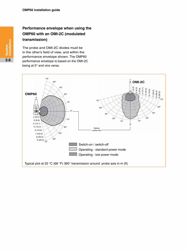
Performance envelope when using the OMP60 with an OMI-2C (modulated transmission) . . . . . . . . . . . . . . . . . . . . . . . . . . . . . . . . . . . . . . . . . . . . 3.6
Preparing the OMP60 for use . . . . . . . . . . . . . . . . . . . . . . . . . . . . . . . . . . . . . . . . . . . . . . . . . . 3.7
Fitting the stylus . . . . . . . . . . . . . . . . . . . . . . . . . . . . . . . . . . . . . . . . . . . . . . . . . . . . . . . . . . 3.7
Installing the batteries . . . . . . . . . . . . . . . . . . . . . . . . . . . . . . . . . . . . . . . . . . . . . . . . . . . . . 3.9
Mounting the probe on a shank (or machine table) . . . . . . . . . . . . . . . . . . . . . . . . . . . . . . 3.10
Stylus on-centre adjustment . . . . . . . . . . . . . . . . . . . . . . . . . . . . . . . . . . . . . . . . . . . . . . . . 3.11
Stylus trigger force and adjustment . . . . . . . . . . . . . . . . . . . . . . . . . . . . . . . . . . . . . . . . . . . . . 3.12
Calibrating the OMP60 . . . . . . . . . . . . . . . . . . . . . . . . . . . . . . . . . . . . . . . . . . . . . . . . . . . . . . 3.13
Why calibrate a probe? . . . . . . . . . . . . . . . . . . . . . . . . . . . . . . . . . . . . . . . . . . . . . . . . . . . 3.13
Calibrating in a bored hole or on a turned diameter . . . . . . . . . . . . . . . . . . . . . . . . . . . . . . 3.13
Calibrating in a ring gauge or on a datum sphere . . . . . . . . . . . . . . . . . . . . . . . . . . . . . . . 3.13
Calibrating the probe length . . . . . . . . . . . . . . . . . . . . . . . . . . . . . . . . . . . . . . . . . . . . . . . . 3.13
Trigger Logic™ . . . . . . . . . . . . . . . . . . . . . . . . . . . . . . . . . . . . . . . . . . . . . . . . . . . 4 .1
Reviewing the current probe settings . . . . . . . . . . . . . . . . . . . . . . . . . . . . . . . . . . . . . . . . . . . . 4.1
Probe settings record . . . . . . . . . . . . . . . . . . . . . . . . . . . . . . . . . . . . . . . . . . . . . . . . . . . . . . . . 4.2
Changing the probe settings . . . . . . . . . . . . . . . . . . . . . . . . . . . . . . . . . . . . . . . . . . . . . . . . . . . 4.4
Operating mode . . . . . . . . . . . . . . . . . . . . . . . . . . . . . . . . . . . . . . . . . . . . . . . . . . . . . . . . . . . . . 4.6
Maintenance . . . . . . . . . . . . . . . . . . . . . . . . . . . . . . . . . . . . . . . . . . . . . . . . . . . . . . 5 .1
Maintenance . . . . . . . . . . . . . . . . . . . . . . . . . . . . . . . . . . . . . . . . . . . . . . . . . . . . . . . . . . . . . . . 5.1
Cleaning the probe . . . . . . . . . . . . . . . . . . . . . . . . . . . . . . . . . . . . . . . . . . . . . . . . . . . . . . . . . . 5.1
Changing the batteries . . . . . . . . . . . . . . . . . . . . . . . . . . . . . . . . . . . . . . . . . . . . . . . . . . . . . . . 5.2
Diaphragm replacement . . . . . . . . . . . . . . . . . . . . . . . . . . . . . . . . . . . . . . . . . . . . . . . . . . . . . . 5.4

iii
Co
nte
nts
OMP60M system . . . . . . . . . . . . . . . . . . . . . . . . . . . . . . . . . . . . . . . . . . . . . . . . . . 6 .1
OMP60M system . . . . . . . . . . . . . . . . . . . . . . . . . . . . . . . . . . . . . . . . . . . . . . . . . . . . . . . . . . . . 6.1
OMP60M dimensions . . . . . . . . . . . . . . . . . . . . . . . . . . . . . . . . . . . . . . . . . . . . . . . . . . . . . . . . 6.2
OMP60M screw torque values . . . . . . . . . . . . . . . . . . . . . . . . . . . . . . . . . . . . . . . . . . . . . . . . . 6.2
Fault-finding . . . . . . . . . . . . . . . . . . . . . . . . . . . . . . . . . . . . . . . . . . . . . . . . . . . . . . 7 .1
Parts list . . . . . . . . . . . . . . . . . . . . . . . . . . . . . . . . . . . . . . . . . . . . . . . . . . . . . . . . . 8 .1

OMP60 installation guide
iv
Co
nte
nts
This page left intentionally blank

1 .1
Before you begin
Disclaimer
RENISHAW HAS MADE CONSIDERABLE EFFORTS TO ENSURE THE CONTENT OF THIS DOCUMENT IS CORRECT AT THE DATE OF PUBLICATION BUT MAKES NO WARRANTIES OR REPRESENTATIONS REGARDING THE CONTENT. RENISHAW EXCLUDES LIABILITY, HOWSOEVER ARISING, FOR ANY INACCURACIES IN THIS DOCUMENT.
Trade marks
RENISHAW and the probe symbol used in the RENISHAW logo are registered trade marks of Renishaw plc in the United Kingdom and other countries. apply innovation and names and designations of other Renishaw products and technologies are trade marks of Renishaw plc or its subsidiaries.
All other brand names and product names used in this document are trade names, trade marks, or registered trade marks of their respective owners.
Warranty
Equipment requiring attention under warranty must be returned to your equipment supplier.
Unless otherwise specifically agreed in writing between you and Renishaw, if you purchased the equipment from a Renishaw company the warranty provisions contained in Renishaw’s CONDITIONS OF SALE apply. You should consult these conditions in order to find out the details of your warranty but in summary the main exclusions from the warranty are if the equipment has been:
• neglected, mishandled or inappropriately used; or
• modified or altered in any way except with the prior written agreement of Renishaw.
If you purchased the equipment from any other supplier, you should contact them to find out what repairs are covered by their warranty.
Changes to equipment
Renishaw reserves the right to change equipment specifications without notice.
CNC machines
CNC machine tools must always be operated by fully trained personnel in accordance with the manufacturer's instructions.
Care of the probe
Keep system components clean and treat the probe as a precision tool.
Before you begin

OMP60 installation guide
1 .2
Bef
ore
yo
u b
egin
Patents
Features of the OMP60 probe, and other similar Renishaw probes, are subject of one or more of the following patents and/or patent applications:
CN 100416216
CN 101476859
EP 0695926
EP 0974208
EP 1130557
EP 1185838
EP 1373995
EP 1425550
EP 1457786
EP 1477767
EP 1477768
EP 1503524
EP 1613921
EP 1701234
EP 1734426
EP 1804020
EP 1988439
IN 234921
IN 8707/DELNP/2008
JP 3967592
JP 4237051
JP 4294101
JP 4754427
JP 4773677
JP 4851488
JP4852411
US 5669151
US 6,776,344 B2
US 6472981
US 6839563
US 6860026
US 6941671
US 7145468
US 7285935
US 7316077
US 7441707
US 7486195
US 7812736

1 .3
Bef
ore
yo
u b
egin
CFCC information to the user (USA only)
47 CFR Section 15 .19
This device complies with Part 15 of the FCC rules.
Operation is subject to the following two conditions:
1. This device may not cause harmful interference.
2. This device may accept any interference received, including interference that may cause undesired operation.
47 CFR Section 15 .21
The user is cautioned that any changes or modifications not expressly approved by Renishaw plc, or authorised representative could void the user’s authority to operate the equipment.
47 CFR Section 15 .105
This equipment has been tested and found to comply with the limits for a Class A digital device, pursuant to Part 15 of the FCC rules. These limits are designed to provide reasonable protection against harmful interference when the equipment is operated in a commercial environment. This equipment generates, uses, and can radiate radio frequency energy and, if not installed and used in accordance with the instruction manual, may cause harmful interference to radio communications. Operation of this equipment in a residential area is likely to cause harmful interference, in which case you will be required to correct the interference at your own expense.
EC declaration of conformity
Renishaw plc declares that the OMP60 optical machine probe complies with the applicable standards and regulations.
Contact Renishaw plc or visit www.renishaw.com/omp60 for the full EC declaration of conformity.
WEEE directive
The use of this symbol on Renishaw products and/or accompanying documentation indicates that the product should not be mixed with general household waste upon disposal. It is the responsibility of the end user to dispose of this product at a designated collection point for waste electrical and electronic equipment (WEEE) to enable reuse or recycling. Correct disposal of this product will help to save valuable resources and prevent potential negative effects on the environment. For more information, please contact your local waste disposal service or Renishaw distributor.

OMP60 installation guide
1 .4
Bef
ore
yo
u b
egin
Safety
Information to the user
The OMP60 is supplied with two non-rechargeable AA alkaline batteries. Lithium Thionyl Chloride non-rechargable AA batteries may also be used in the OMP60 (see 'Changing the batteries' in Section 5 - "Maintenance"). Lithium batteries must be approved to IEC 62133. Once the charge in the batteries is depleted, do not attempt to recharge them.
The use of this symbol on the batteries and/or accompanying packaging indicates that the batteries should not be mixed with general household waste upon disposal. It is the responsibility of the end user to dispose of the batteries at a designated collection point to enable recycling. Correct disposal of the batteries will prevent negative effects on the environment. For more information, please contact your local waste disposal service.
Please ensure replacement batteries are of the correct type and are fitted with the correct polarity in accordance with the instructions in this manual, and as indicated on the product. For specific battery operating, safety and disposal guidelines, please refer to the battery manufacturers' literature.
• Ensure that all batteries are inserted with the correct polarity.
• Do not store batteries in direct sunlight or rain.
• Do not heat or dispose of batteries in a fire.
• Avoid forced discharge of the batteries.
• Do not short-circuit the batteries.
• Do not disassemble, pierce, deform or apply excessive pressure to the batteries.
• Do not swallow the batteries.
• Keep the batteries out of the reach of children.
• Do not get batteries wet.
If a battery is damaged, exercise caution when handling it.
Please ensure that you comply with international and national battery transport regulations when transporting batteries or the products.
Lithium batteries are classified as dangerous goods and strict controls apply to their shipment by air. To reduce the risk of shipment delays, if you need to return the products to Renishaw for any reason, do not return any batteries.
The OMP60 has a glass window. Handle with care if broken to avoid injury.
Information to the machine supplier/
installer
It is the machine supplier's responsibility to ensure that the user is made aware of any hazards involved in operation, including those mentioned in Renishaw product literature, and to ensure that adequate guards and safety interlocks are provided.
Under certain circumstances, the probe signal may falsely indicate a probe seated condition. Do not rely on probe signals to halt the movement of the machine.

1 .5
Bef
ore
yo
u b
egin
Information to the equipment installer
All Renishaw equipment is designed to comply with the relevant EC and FCC regulatory requirements. It is the responsibility of the equipment installer to ensure that the following guidelines are adhered to, in order for the product to function in accordance with these regulations:
• any interface MUST be installed in a position away from any potential sources of electrical noise, i.e. power transformers, servo drives etc;
• all 0 V/ground connections should be connected to the machine "star point" (the "star point" is a single point return for all equipment ground and screen cables). This is very important and failure to adhere to this can cause a potential difference between grounds;
• all screens must be connected as outlined in the user instructions;
• cables must not be routed alongside high current sources, i.e. motor power supply cables etc, or be near high speed data lines;
• cable lengths should always be kept to a minimum.
Equipment operation
If this equipment is used in a manner not specified by the manufacturer, the protection provided by the equipment may be impaired.

OMP60 installation guide
1 .6
Bef
ore
yo
u b
egin
This page left intentionally blank

2 .12 .1
Introduction
The OMP60 is an optical machine tool probe, suitable for use on medium to large machining and mill-turn centres. It is designed to resist optical interference, false triggering and shock.
The OMP60 can be operated in either ‘Legacy’ or ‘Modulated’ optical transmission modes - see probe settings for further details.
When operating in ‘Legacy’ mode, the OMP60 is compatible with an OMM receiver and MI 12 interface or an OMI receiver/interface.
In 'Modulated' mode, the OMP60 becomes compatible for use with an OMM-2 receiver and an OSI interface or an OMI-2, OMI-2T, OMI-2H, OMI-2C receiver/interface to provide substantially increased resistance to light interference.
Also, in 'Modulated' mode, it is possible to define the probe ID. This is factory set to PROBE 1, but can be changed to PROBE 2 for use with twin or PROBE 3 for use with multiple probe systems.
All OMP60 settings are configured using ‘Trigger Logic™’. This technique enables the user to review and subsequently change probe settings by deflecting the stylus whilst observing the LED display.
Configurable settings are:
• Switch-on/switch off method
• Enhanced trigger filter setting
• Optical transmission method
• Optical power
Getting started
Three multicolour probe LEDs provide visual indication of selected probe settings.
For example:
• Switch-on and switch-off methods
• Probe status - triggered or seated
• Battery condition
System interface
The interface conveys and processes signals between the probe and CNC machine control.
OMI-2 / OMI-2T / OMI-2H / OMI-2C / OMM-2 with
OSI (modulated transmission)
The OMI-2T or OMM-2 with OSI are the recommended interfaces for use with the OMP60 as they provide substantially increased resistance to light interference whilst providing the user greater flexibility to operate a multiple probe system.
OMI or OMM with MI 12 (legacy transmission)
Alternative interfaces are the OMI or OMM with the MI 12 interface unit.
MI 7 interface unit
CAUTION: Systems using the earlier MI 7 interface in place of the MI 12 interface are not compatible with OMP60.
OMP60 basics
!

OMP60 installation guide
2 .2
OM
P60
bas
ics
Trigger Logic™
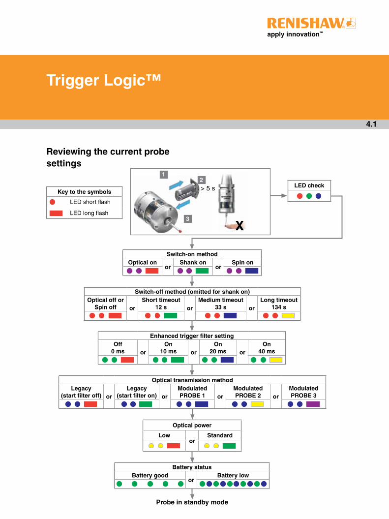
Trigger Logic (see Section 4, "Trigger Logic™") is a method that allows the user to view and select all available mode settings in order to customise a probe to suit a specific application. Trigger Logic is activated by battery insertion and uses a sequence of stylus deflection (triggering) to systematically lead the user through the available choices to allow selection of the required mode options.
Current probe settings can be reviewed by simply removing the batteries for a minimum of 5 seconds, and then replacing them to activate the Trigger Logic review sequence.
Probe modes
The OMP60 probe can be in one of three modes:
Standby mode - Probe is waiting for a switch-on signal.
Operational mode - When activated by one of the switch-on methods, the probe is switched on and ready for use.
Configuration mode - Ready to change the probe settings using Trigger Logic™.
Configurable settings
Switch on / switch off methods
The following switch on / switch off options are user-configurable.
1. Optical on / Optical off
2. Optical on / Timer off
3. Spin on / Spin off
4. Spin on / Timer off
5. Shank switch on / Shank switch off

2 .3
OM
P60
bas
ics
OMP60 switch on method
Switch on options are configurable
OMP60 switch off method
Switch off options are configurable
Switch on time
Optical on
Optical switch on is commanded by machine input.
Optical off
Optical switch off is commanded by machine input. A timer automatically switches the probe off 90 minutes after the last trigger if it is not turned off by machine input.
Timer off (timeout)
Timeout will occur 12, 33 or 134 seconds (user configurable) after the last probe trigger or reseat. Please note that the issue of a further M-code during the time out period, will also reset the timer.
Legacy (start filter off): 0.5 seconds
Legacy (start filter on): 1 second
Modulated: 0.5 seconds
Optical on
Optical switch on is commanded by auto start.
Timer off (timeout)
Timeout will occur 12, 33 or 134 seconds (user configurable) after the last probe trigger or reseat. Please note that the issue of a further M-code during the time out period, will also reset the timer.
Spin on
Spin at 500 rev/min for 1 second minimum.
Spin off
Spin at 500 rev/min for 1 second minimum. A timer automatically switches the probe off 90 minutes after the last trigger if it is not spun.
Timer off (timeout)
Timeout will occur 12, 33 or 134 seconds (user configurable) after the last probe trigger or reseat. Please note that the issue of a further M-code during the time out period, will also reset the timer.
1 second maximum
Shank switch on Shank switch off Approximately 0.5 seconds.

OMP60 installation guide
2 .4
OM
P60
bas
ics
Enhanced trigger filter
Probes subjected to high levels of vibration or shock loads may output probe trigger signals without having contacted any surface. The enhanced trigger filter improves the probe’s resistance to these effects.
When the filter is enabled, a constant nominal 10, 20 or 40 ms delay is introduced to the probe output.
It may be necessary to reduce the probe approach speed to allow for the increased stylus overtravel during the extended time delay.
Factory set to OFF.
Optical transmission method
Probes subjected to particular forms of light interference may accept spurious start signals.
The OMP60 can be operated in either ‘Legacy’ or ‘Modulated’ optical transmission mode.
Legacy mode
A start filter improves the probe’s resistance to these effects.
When Legacy (start filter on) is enabled, an additional one second delay is introduced to the probe activation (switch on) time.
It may be necessary to revise the probe program software to allow for the increased activation time.
Modulated mode
The OMP60 becomes compatible for use with OMI-2, OMI-2T, OMI-2H, OMI-2C and OMM-2 with OSI to provide substantially increased resistance to light interference.
Modulated transmission, in the OMP60, is capable of providing three different coded start signals. This allows the use of two probes with an OMI-2T and up to three probes with an OMM-2/OSI system respectively.
Twin/multiple probe system
To operate in a twin or multiple probe system, one probe needs to be set to PROBE 1 start and the other set to PROBE 2 start (OMI-2T or OMM-2/OSI) or PROBE 3 start (OMM-2/OSI only). These settings are user configurable.
In a twin probe system, such as a spindle probe and an optical tool setting probe, the spindle probe would be set to PROBE 1 start and the tool setter to PROBE 2 start.
In a multiple probe system, with two spindle probes and one optical tool setting probe, the two spindle probes would be set to PROBE 1 and PROBE 2 start, respectively. The tool setter would be set to PROBE 3 start.
Optical power
Where the separation between the OMP60 and the OMI-2, OMI-2T, OMI-2H, OMI-2C, OMM with MI 12 or OMM-2 with OSI is small, low optical power may be used. In this setting, the optical transmission range will be reduced as shown on the performance envelopes, so battery life will be extended.
Dotted lines on the performance envelopes represent the OMP60 in low optical power.
Low optical power should be used whenever possible for increased battery life.
Maximum battery life is achieved when Lithium Thionyl Chloride (LTC) batteries are used in conjunction with low power mode.
The probe is factory set to standard optical power.

2 .5
OM
P60
bas
ics
OMP60 dimensions
Stylus overtravel limits
Stylus length ±X/±Y +Z
50 (1.97) 21 (0.82) 11 (0.43)
100 (3.94) 37 (1.45) 11 (0.43)
Dimensions given in mm (in)
A range of probe-ready shanks are available from Renishaw
50 (1.97) 19 (0.75)Battery cassette
Shank switch (optional)
Window
18°
18°
Ø6
3 (
Ø2
.48
)
76 (2.99)
M4 stylus
Probe status LED
XY overtravel

OMP60 installation guide
2 .6
OM
P60
bas
ics
OMP60 specification
Principal application Workpiece inspection and job set-up on medium to large sized machining centres and mill-turn centres.
Dimensions LengthDiameter
76 mm (2.99 in)63 mm (2.48 in)
Weight (without shank) With batteriesWithout batteries
883.8 g (31.17 oz)834 g (29.42 oz)
Transmission type 360° infrared optical transmission (modulated or legacy)
Switch-on methods Optical M-code, spin on or shank switch
Switch-off methods Optical M-code, timeout, spin off or shank switch
Spindle speed (maximum) 1000 rev/min
Operating range Up to 6 m (19.7 ft)
Compatible Receiver/interface
Modulated OMI-2, OMI-2T, OMI-2H, OMI-2C or OSI/OMM-2
Legacy OMI or OMM/MI 12
Sense directions ±X, ±Y, +Z
Unidirectional repeatability 1.00 µm (40 µin) 2s – 50 mm stylus length (see note 1)
Stylus trigger force (see notes 2 and 3)Factory setting:
XY low forceXY high forceZ
0.75 N, 76 gf (2.70 ozf)1.40 N, 143 gf (5.04 ozf)5.30 N, 540 gf (19.06 ozf)
Maximum setting:XY low forceXY high forceZ
2.00 N, 204 gf (7.19 ozf)3.50 N, 357 gf (12.59 ozf)14.00 N, 1428 gf (50.36 ozf)
Minimum setting:XY low forceXY high forceZ
0.50 N, 51 gf (1.80 ozf)0.90 N, 92 gf (3.24 ozf)3.50 N, 357 gf (12.59 ozf)
Stylus overtravel XY plane+Z plane
±18°11 mm (0.43 in)
Note 1 Performance specification is tested at a standard test velocity of 480 mm/min (18.9 in/min) with ceramic
styli. Significantly higher velocity is possible depending on application requirements.
Note 2 Trigger force, which is critical in some applications, is the force exerted on the component by the stylus
when the probe triggers.
The maximum force applied will occur after the trigger point i.e. overtravel. The force value depends on
related variables including measuring speed and machine deceleration.
Note 3 Tests carried out using a 50 mm (1.97 in) straight stylus.

2 .7
OM
P60
bas
ics
Environment IP rating IPX8 (EN/IEC 60529)
Storage temperature -25 °C to +70 °C (-13 °F to +158 °F)
Operating temperature +5 °C to +55 °C (+41 °F to +131 °F)
Battery types 2 x AA 1.5 V alkaline or 2 x AA 3.6 V Lithium Thionyl Chloride (LTC)
Battery reserve life Approximately one week after a low battery warning is first given.
Typical battery life See page 2.8
Rechargeable batteries
Either Nickel Cadmium (NiCd) or Nickel Metal Hydride (NiMh) can be used. However, when these battery types are fitted, expect a battery life of approximately 50% less than that quoted for alkaline batteries together with a reduced low battery warning period.

OMP60 installation guide
2.8
OM
P60
bas
ics
Modulated transmission
2 x AA 1.5V alkaline batteries (typical)
Optical on/off Shank on/off Spin on/off
Standard power
Low power
Standard power
Low power
Standard power
Low power
Standby 818 days 940 days 304 days
5% usage 134 days 162 days 136 days 165 days 105 days 121 days
Continuous use 190 hours 240 hours 190 hours 240 hours 190 hours 240 hours
2 x AA 3.6V LTC batteries (typical)
Optical on/off Shank on/off Spin on/off
Standard power
Low power
Standard power
Low power
Standard power
Low power
Standby 1597 days 1767 days 722 days
5% usage 359 days 430 days 364 days 438 days 283 days 325 days
Continuous use 550 hours 690 hours 540 hours 690 hours 540 hours 680 hours
Legacy transmission
2 x AA 1.5V alkaline batteries (typical)
Optical on/off Shank on/off Spin on/off
Standard power
Low power
Standard power
Low power
Standard power
Low power
Standby 818 days 940 days 304 days
5% usage 133 days 195 days 135 days 199 days 104 days 139 days
Continuous use 190 hours 300 hours 190 hours 300 hours 190 hours 300 hours
2 x AA 3.6V LTC batteries (typical)
Optical on/off Shank on/off Spin on/off
Standard power
Low power
Standard power
Low power
Standard power
Low power
Standby 1597 days 1767 days 722 days
5% usage 355 days 511 days 360 days 523 days 280 days 369 days
Continuous use 540 hours 880 hours 540 hours 870 hours 530 hours 860 hours
Typical battery life

3 .1
Installing the OMP60
System installation
Operating envelope
The OMP60 / OMI or OMM with MI 12 system uses legacy transmission. The OMP60 / OMM-2 with OSI or OMI-2T or OMI-2H or OMI-2 system uses modulated transmission.
Natural reflective surfaces within the machine may increase the signal transmission range.
Coolant and swarf residue accumulating on the probe or receiver/interface windows, will have a detrimental effect on transmission performance. Wipe clean as often as necessary to maintain unrestricted transmission.
CAUTION: If two or more systems are operating in close proximity to each other, take care to ensure that signals transmitted from the OMP60 on one machine are not received by the receiver on the other machine, and vice versa. When this is the case it is recommended that the OMP60 low optical power is used and that the low range setting is used on the receiver.
OMP60 probe
MI 12 interface unit or MI 12-B
OMM
WorkpieceCNC machine
control
OMI / OMI-2 / OMI-2T / OMI-2H
OMM-2
OSI interface unit
CNC machine control
CNC machine control
!

OMP60 installation guide
3 .2
Sys
tem
in
stal
lati
on
OMM-2 / OMI-2T / OMI-2H / OMI-2 / OMI
or OMM positioning
To assist finding the optimum position for the OMM-2 / OMI-2T / OMI-2H / OMI-2, signal condition is displayed on a multi-coloured LED.
To assist finding the optimum position for the OMI, signal strength is displayed on an OMI multi-coloured LED.
To assist finding the optimum position of the OMM during system installation, signal strength outputs are available on the MI 12 interface.
Performance envelope when using
the OMP60 with an OMM-2 or OMI-2T
or OMI-2H or OMI-2 (modulated
transmission)
The probe and OMM-2 / OMI-2T / OMI-2H / OMI-2 diodes must be in the other's field of view and within the performance envelope shown. The OMP60 performance envelope is based on the OMM-2 / OMI-2T / OMI-2H / OMI-2 being at 0° and vice versa.
OMP60OMM-2OMI-2T OMI-2HOMI-2
0°
Optical centre line
60°
45°
45°
15°
30°
30°
15°
60°
0°
60°
45°
45°
15°
30°
30°
15°
60°
75°
4 (13.1)
3 (9.8)
2 (6.5)
1 (3.3)
5 (16.4)
4 (13.1)
3 (9.8)
2 (6.5)
1 (3.3)
5 (16.4)
75°
75°
75°
Switch-on / switch-off
Operating - standard power mode
Operating - low power mode
Typical plot at 20 °C (68 °F) 360° transmission around probe axis in m (ft)
6 (19.9) 6 (19.9)

Typical plot at 20 °C (68 °F) 360° transmission around probe axis in m (ft)
OMP60
0°
60°
45°
45°
15°
30°
30°
15°
60°
0°
60°
45°
45°
15°
30°
30°
15°
60°
75°
4 (13.1)
3 (9.8)
2 (6.5)
1 (3.3)
5 (16.4)
4 (13.1)
3 (9.8)
2 (6.5)
1 (3.3)
5 (16.4)
75°
75°
75°
OMI
Optical centre line
6 (19.9) 6 (19.9)
Switch-on / switch-off
Operating - standard power mode
Operating - low power mode
3 .3
Sys
tem
in
stal
lati
on
Performance envelope when using
the OMP60 with an OMI (legacy
transmission)
The probe and OMI diodes must be in each other's field of view and within the performance envelope shown. The OMP60 performance envelope is based on the OMI being at 0° and vice versa.

Typical plot at 20 °C (68 °F) 360° transmission around probe axis in m (ft)
Switch-on / switch-off
Operating - standard power mode
Operating - low power mode
Performance envelope when using
the OMP60 with an OMM (legacy
transmission)
The probe and OMM diodes must be in the other's field of view and within the performance envelope shown. The OMP60 performance envelope is based on the OMM being at 0° and vice versa.
OMP60
0°
60°
45°
45°
15°
30°
30°
15°
60°
0°
60°
45°
45°
15°
30°
30°
15°
60°
75°
4 (13.1)
3 (9.8)
2 (6.5)
1 (3.3)
5 (16.4)
4 (13.1)
3 (9.8)
2 (6.5)
1 (3.3)
5 (16.4)
75°
75°
75°
OMM
Optical centre line
6 (19.9) 6 (19.9)
OMP60 installation guide
3 .4
Sys
tem
in
stal
lati
on

CNC machining centre spindle
OMP60 inspection
probe
Installing the OMP60 with an OMI-2C
Operating envelope
Reflective surfaces within the machine cabinet may increase the signal transmission range.
Coolant residue accumulating on the windows of the OMI-2C and OMP60 will have a detrimental effect on transmission performance. Wipe the windows clean as often as is necessary to maintain unrestricted transmission.
For best system performance, ensure that the OMI-2C is mounted in a position which is not directly in front of a light source.
CAUTION: If two or more systems are operating in close proximity to each other, take care to ensure that signals transmitted from the OMP60 on one machine are not received by the receiver on the other machine, and vice versa. When this is the case it is recommended that the OMP60 low optical power is used.
OMI-2C position
WARNING: Ensure the machine tool is in a safe condition and power is removed before removing covers. Only qualified persons should adjust switches.
CAUTION: Different versions of the OMI-2C operate with specific machine controls. Prior to installation, ensure that the OMI-2C is compatible with the machine controller.
The OMI-2C should be mounted as near to the machine spindle as possible.
To achieve the best possible transmission range and performance envelope, it is recommended that the mounting screw is positioned on the far side of the OMI-2C, relative to the expected probe position.
When mounting the OMI-2C, it is important that the sealing ring forms a tight seal around the rim of the bore into which the body of the OMI-2C is to be located.
Cable
CNC machine control
OMI-2C (optical
machine interface)
Stylus
Workpiece
3 .5
Sys
tem
in
stal
lati
on
!
!
!
Typical plot at 20 °C (68 °F) 360° transmission around probe axis in m (ft)
Switch-on / switch-off
Operating - standard power mode
Operating - low power mode
Performance envelope when using the
OMP60 with an OMI-2C (modulated
transmission)
The probe and OMI-2C diodes must be in the other’s field of view, and within the performance envelope shown. The OMP60 performance envelope is based on the OMI-2C being at 0° and vice versa.
OMP60
75°
60°
45°
30°
15°
0°
15°
30°
45°
60°75°
6 (19.9)
5 (16.4)
4 (13.1)
3 (9.8)
2 (6.5)
1 (3.3)
75°
60°
45°
30°
15°
0°
15°
30°
45°
60°
OMI-2C
Optical centre line
9 (29.5)
8 (26.2)
7 (23.0)
6 (
19.9
)
5 (
16.4
)
4 (
13.1
)
3 (
9.8
)
2 (
6.5
)
1 (
3.3
)
9 (
29.5
)
8 (
26.2
)
7 (
23.0
)
75°
OMP60 installation guide
3 .6
Sys
tem
in
stal
lati
on

1
2
3 .7
Sys
tem
in
stal
lati
on
Preparing the OMP60 for use
Fitting the stylus
M-5000-3707
1.8 Nm – 2.2 Nm (1.3 lbf.ft – 1.6 lbf.ft)

1
2
OMP60 installation guide
3 .8
Sys
tem
in
stal
lati
on
Stylus weak link
NOTE: Must be used with steel styli. For optimum metrology performance do not use a weak link with ceramic or carbon fibre styli.
Fitting stylus with weak link onto OMP60
In the event of excessive stylus overtravel, the weak link is designed to break, thereby protecting the probe from damage.
Take care to avoid stressing the weak link during assembly.
Removing a broken weak link
2 Nm (1.5 lbf.ft)
5 mm AF2 Nm (1.5 lbf.ft)
12 mm(0.47 in)
1
2
3 4
X
3 .9
Sys
tem
in
stal
lati
on
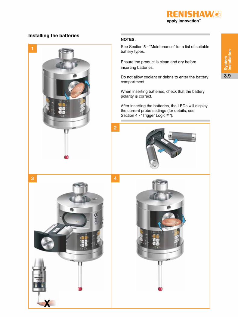
Installing the batteriesNOTES:
See Section 5 - "Maintenance" for a list of suitable battery types. Ensure the product is clean and dry before inserting batteries. Do not allow coolant or debris to enter the battery compartment. When inserting batteries, check that the battery polarity is correct. After inserting the batteries, the LEDs will display the current probe settings (for details, see Section 4 - "Trigger Logic™").
1
32
OMP60 installation guide
3 .10
Sys
tem
in
stal
lati
on
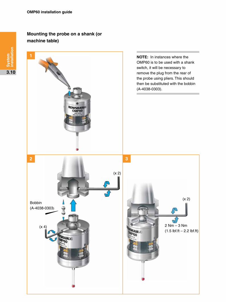
Mounting the probe on a shank (or
machine table)
2 Nm – 3 Nm(1.5 lbf.ft – 2.2 lbf.ft)
NOTE: In instances where the OMP60 is to be used with a shank switch, it will be necessary to remove the plug from the rear of the probe using pliers. This should then be substituted with the bobbin (A-4038-0303).
Bobbin(A-4038-0303)
(x 2)
(x 2)
(x 4)
1
2 3
3 .11
Sys
tem
in
stal
lati
on
1 Nm(0.74 lbf.ft)
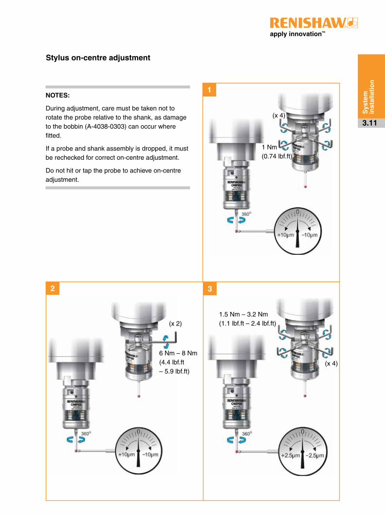
Stylus on-centre adjustment
6 Nm – 8 Nm(4.4 lbf.ft – 5.9 lbf.ft)
1.5 Nm – 3.2 Nm(1.1 lbf.ft – 2.4 lbf.ft)
NOTES:
During adjustment, care must be taken not to rotate the probe relative to the shank, as damage to the bobbin (A-4038-0303) can occur where fitted.
If a probe and shank assembly is dropped, it must be rechecked for correct on-centre adjustment.
Do not hit or tap the probe to achieve on-centre adjustment.
(x 4)
(x 2)
(x 4)
OMP60 installation guide
3 .12
Sys
tem
in
stal
lati
on
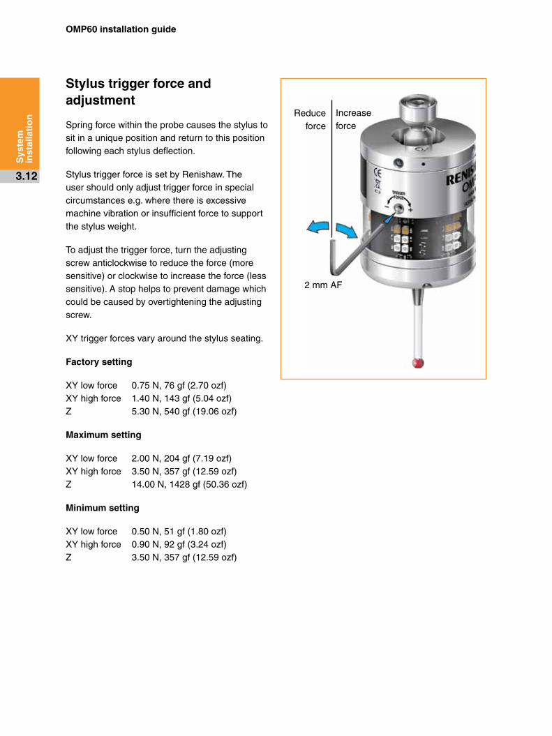
Stylus trigger force and adjustment
Spring force within the probe causes the stylus to sit in a unique position and return to this position following each stylus deflection.
Stylus trigger force is set by Renishaw. The user should only adjust trigger force in special circumstances e.g. where there is excessive machine vibration or insufficient force to support the stylus weight.
To adjust the trigger force, turn the adjusting screw anticlockwise to reduce the force (more sensitive) or clockwise to increase the force (less sensitive). A stop helps to prevent damage which could be caused by overtightening the adjusting screw.
XY trigger forces vary around the stylus seating.
Factory setting
XY low force 0.75 N, 76 gf (2.70 ozf)XY high force 1.40 N, 143 gf (5.04 ozf)Z 5.30 N, 540 gf (19.06 ozf)
Maximum setting
XY low force 2.00 N, 204 gf (7.19 ozf)XY high force 3.50 N, 357 gf (12.59 ozf)Z 14.00 N, 1428 gf (50.36 ozf)
Minimum setting
XY low force 0.50 N, 51 gf (1.80 ozf)XY high force 0.90 N, 92 gf (3.24 ozf)Z 3.50 N, 357 gf (12.59 ozf)
Reduce force
Increase force
2 mm AF

3 .13
Sys
tem
in
stal
lati
on
Calibrating the OMP60
Why calibrate a probe?
A spindle probe is just one component of the measurement system which communicates with the machine tool. Each part of the system can introduce a constant difference between the position that the stylus touches and the position that is reported to the machine. If the probe is not calibrated, this difference will appear as an inaccuracy in the measurement. Calibration of the probe allows the probing software to compensate for this difference.
During normal use, the difference between the touch position and the reported position does not change, but it is important that the probe is calibrated in the following circumstances:
• when a probe system is to be used for the first time;
• when the enhanced trigger filter delay is changed;
• when a new stylus is fitted to the probe;
• when it is suspected that the stylus has become distorted or that the probe has crashed;
• at regular intervals to compensate for mechanical changes of your machine tool;
• if repeatability of relocation of the probe shank is poor. In this case, the probe may need to be recalibrated each time it is selected.
It is good practice to set the tip of the stylus on-centre, because this reduces the effect of any variation in spindle and tool orientation (see 'Stylus on-centre adjustment' in Section 3 - "System Installation"). A small amount of run-out is acceptable, and can be compensated for as part of the normal calibration process.
Three different operations are to be used when calibrating a probe. They are:
• calibrating either in a bored hole or on a turned diameter of known position;
• calibrating either in a ring gauge or on a datum sphere;
• calibrating the probe length.
Calibrating in a bored hole or on a
turned diameter
Calibrating a probe, either in a bored hole or on a turned diameter of known size, automatically stores values for the offset of the stylus ball to the spindle centre-line. The stored values are then used automatically in the measuring cycles. Measured values are compensated by these values so that they are relative to the true spindle centre-line.
Calibrating in a ring gauge or on a
datum sphere
Calibrating a probe either in a ring gauge or on a datum sphere with a known diameter automatically stores one or more value for the radius of the stylus ball. The stored values are then used automatically by the measuring cycles to give the true size of the feature. The values are also used to give true positions of single surface features.
NOTE: The stored radius values are based on the true electronic trigger points. These values are different from the physical sizes.
Calibrating the probe length
Calibrating a probe on a known reference surface determines the length of the probe, based on the electronic trigger point. The stored value for length is different from the physical length of the probe assembly. Additionally, the operation can automatically compensate for machine and fixture height errors by adjusting the probe length value that is stored.

OMP60 installation guide
3 .14
Sys
tem
in
stal
lati
on
This page left intentionally blank
X
4 .1
> 5 s
12
3
Key to the symbols
LED short flash
LED long flash
Switch-on methodOptical on
orShank on
orSpin on
Switch-off method (omitted for shank on)Optical off or
Spin off orShort timeout
12 s orMedium timeout
33 s orLong timeout
134 s
LED check
Probe in standby mode
Battery statusBattery good
orBattery low
Optical power
Lowor
Standard
Reviewing the current probe settings
Trigger Logic™
Enhanced trigger filter settingOff
0 ms orOn
10 ms orOn
20 ms orOn
40 ms
Optical transmission methodLegacy
(start filter off) orLegacy
(start filter on) orModulated PROBE 1 or
Modulated PROBE 2 or
Modulated PROBE 3

OMP60 installation guide
4 .2
Trig
ger
Lo
gic
™
Factory settings
New settings
Switch-on method Optical on ✔
Shank on
Spin on
Switch-off method Optical off or spin off ✔
Short timeout (12 s)
Medium timeout (33 s)
Long timeout (134 s)
Enhanced trigger filter setting
Off (0 ms) ✔
On (10 ms)
On (20 ms)
On (40 ms)
Optical transmission method
Legacy (start filter off)
Legacy (start filter on)
Modulated PROBE 1 ✔
Modulated PROBE 2
Modulated PROBE 3
Optical power Low
Standard ✔
OMP60 serial no . . . . . . . . . . . . . . . . . . . . . . . . . . . . . . . . . . . . . . . .
✔ tickProbe settings record
This page is provided to note your probe's settings.
✔ tick
Factory settings are for kit (A-4038-2001) only .

4 .3
Trig
ger
Lo
gic
™
This page left intentionally blank

X
OMP60 installation guide
4 .4
Trig
ger
Lo
gic
™
Switch-on method
Optical on Shank on Spin on
> 5 s12
3
Key to the symbols
LED short flash
LED long flash
Deflect the stylus for less than 4 seconds to move to the next menu option.
Deflect the stylus for more than 4 seconds to move to the next menu.
To exit, leave the stylus untouched for more than 20 seconds.
LED check
Changing the probe settings
Insert the batteries or, if they have already been installed, remove them for five seconds and then refit them.
Following the LED check, immediately deflect the stylus and hold it deflected until five red flashes have been observed (if the battery power is low then each of the five red flashes will be followed by a blue flash).
Keep the stylus deflected until the "Switch on method" setting is displayed, then release the stylus. The probe is now in configuration mode and Trigger Logic™ is activated.
CAUTION: Do not remove the batteries whilst in the configuration mode. Leave the stylus untouched for > 20 seconds to exit.
Switch-off method (omitted for shank on)
Optical off or
Spin off
Short timeout
12 s
Medium timeout
33 s
Long timeout 134 s
continued on next page
3!
Battery status
or
Battery good
Battery low
4.5
Trig
ger
Lo
gic
™
Return to “Change switch-on method”
New settings complete
Optical power
Low Standard
Enhanced trigger filter setting
Off 0 ms
On 10 ms
On 20 ms
On 40 ms
Optical transmission method
Legacy (start filter off)
Legacy (start filter on)
Modulated PROBE 1
Modulated PROBE 2
Modulated PROBE 3
OMP60 installation guide
4 .6
Trig
ger
Lo
gic
™
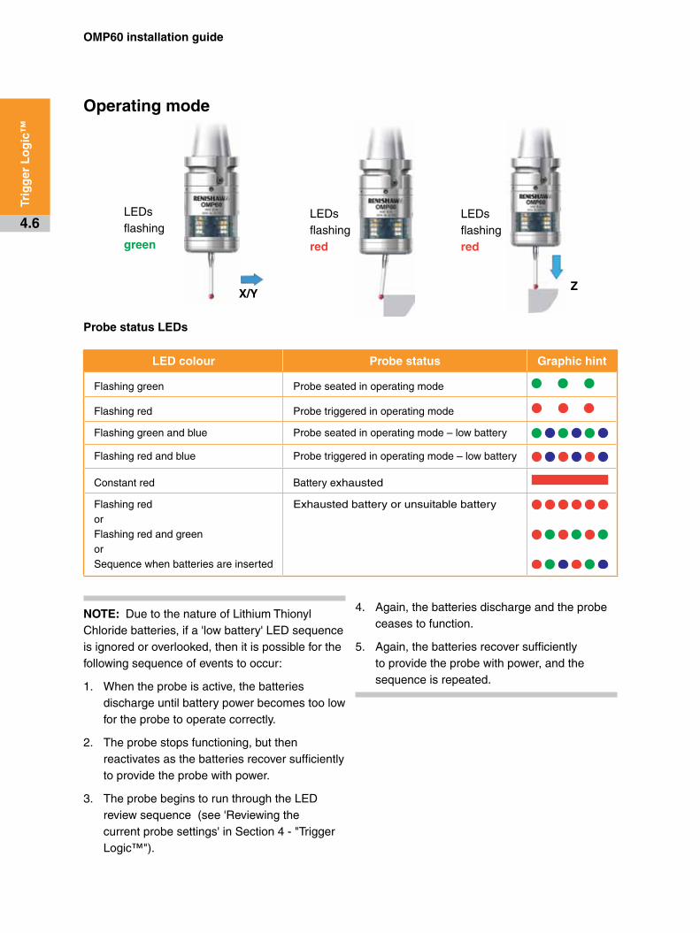
Operating mode
NOTE: Due to the nature of Lithium Thionyl Chloride batteries, if a 'low battery' LED sequence is ignored or overlooked, then it is possible for the following sequence of events to occur:
1. When the probe is active, the batteries discharge until battery power becomes too low for the probe to operate correctly.
2. The probe stops functioning, but then reactivates as the batteries recover sufficiently to provide the probe with power.
3. The probe begins to run through the LED review sequence (see 'Reviewing the current probe settings' in Section 4 - "Trigger Logic™").
LED colour Probe status Graphic hint
Flashing green Probe seated in operating mode
Flashing red Probe triggered in operating mode
Flashing green and blue Probe seated in operating mode – low battery
Flashing red and blue Probe triggered in operating mode – low battery
Constant red Battery exhausted
Flashing red orFlashing red and green orSequence when batteries are inserted
Exhausted battery or unsuitable battery
LEDs flashing green
LEDs flashing red
LEDs flashing red
X/YZ
Probe status LEDs
4. Again, the batteries discharge and the probe ceases to function.
5. Again, the batteries recover sufficiently to provide the probe with power, and the sequence is repeated.

5 .1
Maintenance
You may undertake the maintenance routines described in these instructions.
Further dismantling and repair of Renishaw equipment is a highly specialised operation, which must be carried out at authorised Renishaw Service Centres.
Equipment requiring repair, overhaul or attention under warranty should be returned to your supplier.
Cleaning the probe
Wipe the window of the probe with a clean cloth to remove machining residue. This should be done on a regular basis to maintain optimum transmission.
Maintenance

1
2
OMP60 installation guide
5 .2
Mai
nte
nan
ce CAUTIONS:
Do not leave exhausted batteries in the probe.
When changing batteries, do not allow coolant or debris to enter the battery compartment.
When changing batteries, check that the battery polarity is correct.
Take care to avoid damaging the battery cassette gasket.
Only use specified batteries.
Changing the batteries
CAUTION: Please dispose of exhausted batteries in accordance with local regulations. Never dispose of batteries in a fire.
!
!
3
4 5
X
5 .3
Mai
nte
nan
ce
NOTES:
After removing the old batteries, wait more than 5 seconds before inserting the new batteries.
Do not mix new and used batteries or battery types, as this will result in reduced life and damage to the batteries.
Always ensure that the cassette gasket and mating surfaces are clean and free from dirt before reassembly.
If exhausted batteries are inadvertently inserted into the probe, the LEDs will remain a constant red.
Battery types
Alkalinex2
Lithium Thionyl Chloridex2
Nickel Cadmium/Nickel Metal Hydride x2
AA 1 .5 V Saft:Sonnenschein:Tadrian:Xeno:
LS 14500SL-760/STL-5903/S, TL-2100/SXL-060F
AA 1 .2 V
33 3

OMP60 installation guide
5 .4
Mai
nte
nan
ce
Diaphragm replacement
OMP60 diaphragms
The probe mechanism is protected from coolant and debris by two diaphragms. These provide adequate protection under normal working conditions.
You should periodically check the outer diaphragm for signs of damage. If this is evident, replace the outer diaphragm.
Do not remove the inner diaphragm. If it is damaged, return the probe to your supplier for repair.
Outer diaphragm inspection
1. Remove the stylus.
2. Undo the three M3 front cover screws and remove the front cover.
3. Inspect the outer diaphragm for damage.
4. To remove the outer diaphragm, grip by the outer edge and pull off.
Inner diaphragm inspection
Inspect the inner diaphragm for damage. If it is damaged, return the probe to your supplier. DO NOT REMOVE THE INNER DIAPHRAGM AS YOUR WARRANTY WILL BE INVALIDATED.
Outer diaphragm replacement
1 Fit the new diaphragm over the centre.
2. Locate the outer edge of the diaphragm to rest on the outer edge of the inner diaphragm.
3. Refit the front cover and M3 screws.
4. Refit the stylus and recalibrate the probe.
M3 screw2.5 mm AF 1 Nm (0.74 lbf.ft)
Cover
Outer diaphragm
Inner diaphragm
OMP60M
module
OMP60M /LP2 adaptor
M4 stylus
OMP60M probe
module
M4 stylusLP2 probe
MA4 90° adaptor
LPE3 extension bar (150 mm)
LPE2 extension bar (100 mm)
LPE1 extension bar (50 mm)
OMP60M extension L200
OMP60M extension L150
OMP60M extension L100
6 .1
OMP60M system
OMP60M is a special modular version of OMP60. It enables probe inspection of part features inaccessible to OMP60, by fitting selected adaptors and extensions as shown below.
See Chapter 8 - "Parts list".
NOTE: Maximum spindle speed 750 rev/min.
OMP60M system
OMP60 installation guide
6 .2
OM
P60
M s
yste
m
OMP60M screw torque values
10 Nm to 12 Nm
(7.37 lbf.ft to 8.85 lbf.ft)2.6 Nm
(1.92 lbf.ft)
2.6 Nm
(1.92 lbf.ft)
2.6 Nm
(1.92 lbf.ft)
OMP60M dimensions
Dimensions given in mm (in)
100/150/200 (3.94/5.91/7.88) 67.25 (2.65)
67.25 (2.65)50/100/150
(1.97/3.94/5.91)
12.50 (0.49)
40.75 (1.60)
Ø25
(Ø
0.9
8)
50.50 (1.99)
Ø63
(Ø
4.4
8)
7 .1
Symptom Cause Action
Probe fails to power up (no LEDs illuminated or fails to indicate current probe settings) .
Exhausted batteries. Change batteries.
Unsuitable batteries. Change batteries.
Batteries inserted incorrectly. Check battery insertion.
Batteries removed for too short a time and probe has not reset.
Remove batteries for a minimum of 5 seconds.
Probe fails to switch on (optical on is required) .
Wrong transmit mode selected. Reconfigure transmit mode.
Wrong switch on mode selected. Reconfigure to optical on mode.
Exhausted batteries. Change batteries.
Unsuitable batteries. Change batteries.
Batteries inserted incorrectly. Check battery insertion.
Optical/magnetic interference. Check for interfering lights or motors. Consider removing interfering source.
Probe out of range/not aligned with receiver.
Check the OMP60 and receiver windows are clean, and remove any obstruction.
Transmission beam obstructed. Check configuration and alter as required.
No receiver start signal. Check start signal by reviewing receiver LED.Refer to relevant user's guide.
No power to MI 12 or receiver. Check if stable 24 V supply is available.Check connections and fuses.
Fault-finding

OMP60 installation guide
7 .2
Fau
lt-f
ind
ing
Symptom Cause Action
Probe fails to switch on (shank on is required) .
Wrong switch on mode is selected.
Reconfigure to shank on mode.
Exhausted batteries. Change batteries.
Unsuitable batteries. Change batteries.
Batteries inserted incorrectly. Check battery insertion.
Malfunctioning shank switch. Check switch operation.
No bobbin installed. Install bobbin.
Probe fails to switch on (spin on is required) .
Wrong switch on mode is selected.
Reconfigure to spin on mode.
Exhausted batteries. Change batteries.
Unsuitable batteries. Change batteries.
Batteries inserted incorrectly. Check battery insertion.
Incorrect spindle speed selected. Program correct spindle speed duration.
Excessive spindle vibration. Review probing software.
Machine stops unexpectedly during a probing cycle .
Optical communication obstructed. Check interface/receiver and remove obstruction.
Interface/receiver/machine fault. Refer to interface/receiver/machine user’s guide.
Exhausted batteries. Change batteries.
Probe unable to find target surface.
Check that part is correctly positioned and that stylus has not broken.
False probe trigger. Adjust stylus trigger force and/or enable enhanced trigger filter.
Adjacent probe. Reconfigure to low power mode and reduce range of receiver.

7 .3
Fau
lt-f
ind
ing
Symptom Cause Action
Probe crashes . Inspection probe using tool setting probe signals.
When two systems are active, isolate tool setting probe.
Workpiece obstructing probe path.
Review probing software.
Adjacent probe. Reconfigure to low power mode and reduce range of receiver.
Probe length offset missing. Review probing software.
Poor probe repeatability and/or accuracy .
Debris on part or stylus. Clean part and stylus.
Poor tool change repeatability. Redatum probe after each tool change.
Loose probe mounting on shank or loose stylus.
Check and tighten as appropriate.
Calibration out of date and/or incorrect offsets.
Review probing software.
Calibration and probing speeds not the same.
Review probing software.
Calibration feature has moved. Correct position.
Measurement occurs as stylus leaves surface.
Review probing software.
Measurement occurs within the machine’s acceleration and deceleration zone.
Review probing software and probe filter settings.
Probing speed too high or too slow.
Perform simple repeatability trials at various speeds.
Temperature variation causes machine and workpiece movement.
Minimise temperature changes.

OMP60 installation guide
7 .4
Fau
lt-f
ind
ing
Symptom Cause Action
Probe fails to switch off (optical off is required) .
Wrong switch off mode selected. Reconfigure to optical off mode.
Optical/magnetic interference. Check for interfering lights or motor.
Probe is inadvertently switched on by the receiver when using autostart.
Check position of receiver. Reduce receiver signal strength.
Probe out of range. Review performance envelopes.
Probe is regularly falsely switched-on by light interference.
Enable optical transmission legacy mode (start filter on), or select modulated when modulated receiver is used.
Probe fails to switch off (shank off is required) .
Malfunctioning switch. Check switch operation.
Probe fails to switch off (spin off is required) .
Wrong switch off mode selected. Reconfigure to spin off mode.
Incorrect spindle speed is selected.
Program correct spindle speed /duration.
Excessive spindle vibration. Consider use of optical or shank switch on.
Probe fails to switch off (timeout is required) .
Incorrect switch off method configured.
Reconfigure to timeout mode.
Probe placed in carousel, when in timeout mode, timer can be reset by carousel activity.
Use lighter styli.
Probe fails to communicate with interface after spin or shank on .
Wrong transmit mode selected optical/magnetic interference.
Reconfigure transmit mode. Check for interfering lights or motors. Consider removing interfering source.

8 .1
Type Part number Description
OMP60 A-4038-0001 OMP60 probe with batteries, tool kit and quick-start guide (set to optical on/optical off) - legacy transmission.
OMP60 A-4038-0002 OMP60 probe with batteries, tool kit and quick-start guide (set to optical on/time off 134 sec) - legacy transmission.
OMP60 A-4038-2001 OMP60 probe with batteries, tool kit and quick-start guide (set to optical on/optical off) - modulated transmission, probe 1 start.
OMP60 A-4038-2002 OMP60 probe with batteries, tool kit and quick-start guide (set to optical on/time off 134 sec) - modulated transmission, probe 1 start.
Battery P-BT03-0005 AA battery – alkaline type – supplied as standard with probe (two required).
Battery P-BT03-0008 AA battery – Lithium Thionyl Chloride (two required).
Stylus A-5000-3709 PS3-1C ceramic stylus 50 mm long with Ø6 mm ball.
Weak link kit A-2085-0068 Weak link (Part no. M-2085-0069 x 2) and 5 mm AF spanner.
Tool kit A-4038-0304 Probe tool kit comprising Ø1.98 mm stylus tool, 2.0 mm AF hexagon key, 2.5 mm AF hexagon key (x 2), 4.0 mm AF hexagon key (x 2) and shank grub screw (x 2).
Battery cassette A-4038-0300 OMP60 battery cassette assembly.
Cassette seal A-4038-0301 Battery cassette housing seal.
Diaphragm kit A-4038-0302 OMP60 diaphragm kit.
External eyelid kit A-4038-0305 External eyelid kit for OMP60.
Bobbin kit A-4038-0303 Bobbin for shank switch (supplied with shank).
OMM A-2033-0576 OMM complete with cable Ø4.85 mm x 25 m (Ø0.19 in x 82 ft).
OMI A-2115-0001 OMI complete with cable Ø4.35 mm x 8 m (Ø0.17 in x 26.25 ft).
OMI-2 A-5191-0049 OMI-2 complete with cable 8 m (26.25 ft) long.
OMI-2T A-5439-0049 OMI-2T complete with cable 8 m (26.25 ft) long.
OMI-2C A-5314-0015 OMI-2C complete with cable 8 m (26.25 ft) long.
Parts list

OMP60 installation guide
8 .2
Par
ts li
st
Type Part number Description
OMM-2 A-5492-0049 OMM-2 with 8 m (26 ft) cable, tool kit and quick start guide.
MI 12 interface A-2075-0142 MI 12 interface unit.
MI 12B A-2075-0141 MI 12B interface unit.
Mounting kit A-2033-0690 Panel mounting kit for MI 12 interface unit
OSI interface A-5492-2000 OSI (Multiple Probe Mode) with DIN rail mounting, terminal block and quick start guide.
OSI interface A-5492-2010 OSI (Single Probe Mode) with DIN rail mounting, terminal block and quick start guide.
Mounting bracket A-2033-0830 Mounting bracket with fixing screws, washers and nuts.
Styli tool M-5000-3707 Tool for tightening/releasing styli.
OMP60M module A-4038-1003 OMP60M module with batteries, tool kit and quick-start guide (set to optical on/optical off) - legacy transmission.
OMP60M module A-4038-0368 OMP60M module with batteries, tool kit and quick-start guide (set to optical on/time off 134 sec) - legacy transmission.
OMP60M module A-4038-0369 OMP60M module with batteries, tool kit and quick-start guide (set to optical on/optical off) - modulated transmission, probe 1 start.
OMP60M module A-4038-0370 OMP60M module with batteries, tool kit and quick-start guide (set to optical on/time off 134 sec) - modulated transmission, probe 1 start.
LP2 A-2063-6098 LP2 probe complete with two C spanners and TK1 tool kit.
Extension L100 A-4038-1010 OMP60M extension - 100 mm long.
Extension L150 A-4038-1027 OMP60M extension - 150 mm long.
Extension L200 A-4038-1028 OMP60M extension - 200 mm long.
OMP60/OMP60M probe module assembly
A-4038-1002 OMP60M probe module assembly.
OMP60M/LP2 adaptor
A-4038-0212 OMP60M LP2 adaptor assembly.
LPE1 A-2063-7001 LPE1 extension bar - 50 mm long.
LPE2 A-2063-7002 LPE2 extension bar - 100 mm long.
LPE3 A-2063-7003 LPE3 extension bar - 150 mm long.
MA4 A-2063-7600 MA4 90° adaptor assembly.

8 .3
Par
ts li
st
Type Part number Description
Publications . These can be downloaded from our web site at www.renishaw.com
OMP60 A-4038-8501 Quick-start guide: for rapid set-up of the OMP60 probe, includes CD with installation guides.
OMM H-2000-5044 Installation and user's guide: OMM – optical module machine.
MI 12 H-2000-5073 Installation and user's guide: MI 12 – machine interface unit.
OMI H-2000-5062 Installation and user's guide: OMI – optical machine interface.
OMI-2 H-2000-5233 Installation and user's guide: OMI-2 – optical machine interface.
OMI-2T A-5439-8500 Quick-start guide: for rapid set-up of the OMI-2T, includes CD with installation guides.
OMI-2C H-2000-5256 Installation and user's guide: OMI-2C – optical machine interface.
OMM-2 A-5492-8550 Quick-start guide: for rapid set-up of the OMM-2, includes CD with installation guides.
OSI A-5492-8500 Quick-start guide: for rapid set-up of the OSI, includes CD with installation guides.
Software features H-2000-2289 Data sheet: Probe software for machine tools – illustrated features.
Software list H-2000-2298 Data sheet: Probe software for machine tools – list of programs.
Taper shanks H-2000-2011 Data sheet: Taper shanks for machine tool probes.
Styli H-1000-3200 Technical specification: Styli and accessories.

Renishaw plc
New Mills, Wotton-under-Edge, Gloucestershire, GL12 8JR United Kingdom
T +44 (0)1453 524524 F +44 (0)1453 524901 E [email protected]
www .renishaw .com
For worldwide contact details, please visit our main website at
www .renishaw .com/contact
*H-4038-8505-02*© 2008 - 2013 Renishaw plc Issued 01.2013 Part no. H-4038-8505-02-A