on a cpg-based hexapod robot: amphihex-ii with variable
TRANSCRIPT

University of Wollongong University of Wollongong
Research Online Research Online
Faculty of Engineering and Information Sciences - Papers: Part B
Faculty of Engineering and Information Sciences
2018
On a CPG-based Hexapod Robot: AmphiHex-II with Variable Stiffness Legs On a CPG-based Hexapod Robot: AmphiHex-II with Variable Stiffness Legs
Bin Zhong University of Science and Technology of China
Shiwu Zhang University of Science and Technology of China, [email protected]
Min Xu University of Science and Technology of China, [email protected]
Youcheng Zhou University of Science and Technology of China
Tao Fang University of Science and Technology of China
See next page for additional authors
Follow this and additional works at: https://ro.uow.edu.au/eispapers1
Part of the Engineering Commons, and the Science and Technology Studies Commons
Recommended Citation Recommended Citation Zhong, Bin; Zhang, Shiwu; Xu, Min; Zhou, Youcheng; Fang, Tao; and Li, Weihua, "On a CPG-based Hexapod Robot: AmphiHex-II with Variable Stiffness Legs" (2018). Faculty of Engineering and Information Sciences - Papers: Part B. 1303. https://ro.uow.edu.au/eispapers1/1303
Research Online is the open access institutional repository for the University of Wollongong. For further information contact the UOW Library: [email protected]

On a CPG-based Hexapod Robot: AmphiHex-II with Variable Stiffness Legs On a CPG-based Hexapod Robot: AmphiHex-II with Variable Stiffness Legs
Abstract Abstract Amphibious robots have attracted more and more attention from researchers for their broad applications, while it also brings great challenges in designing appropriate propulsion mechanisms and effective control algorithms. In this paper, we reported a newly designed amphibious hexapod robot-AmphiHex-II. This robot possesses six newly designed variable stiffness legs for adapting various complex environments. This novel design of the variable stiffness leg seamlessly incorporates the advantages of both semi-circular walking legs and the swimming flexible flippers. The legs are constructed by rigid fan-shaped frames which work as walking legs for terrestrial locomotion and protect the contained flexible flippers used for aquatic locomotion during terrestrial operations. The stiffness of legs can be adjusted to an effective degree by adjusting the positions of sliders manually. The effect of variable stiffness on locomotion performance was experimentally investigated. Moreover, in order to achieve a smooth and quick gait transition, a Central Pattern Generator (CPG) neural network was introduced to control the system. Different gait generation strategies on land and underwater were demonstrated. A series of field experiments were carried out to evaluate locomotion performance of the AmphiHex-II for terrestrial and aquatic mobility, and the results demonstrate the advantages of the novel leg design and the control system.
Disciplines Disciplines Engineering | Science and Technology Studies
Publication Details Publication Details Zhong, B., Zhang, S., Xu, M., Zhou, Y., Fang, T. & Li, W. (2018). On a CPG-based Hexapod Robot: AmphiHex-II with Variable Stiffness Legs. IEEE-ASME Transactions on Mechatronics, 23 (2), 542-551.
Authors Authors Bin Zhong, Shiwu Zhang, Min Xu, Youcheng Zhou, Tao Fang, and Weihua Li
This journal article is available at Research Online: https://ro.uow.edu.au/eispapers1/1303
On a CPG-based Hexapod Robot: AmphiHex-II with Variable Stiffness Legs
Bin Zhong, Shiwu Zhang, Min Xu, Youcheng Zhou, Tao Fang, Weihua Li
Abstract—Amphibious robots have attracted more and more attention from researchers for their broad applications, while it also brings great challenges in designing appropriate propulsion mechanisms and effective control algorithms. In this paper, we reported a newly designed amphibious hexapod robot-AmphiHex-II. This robot possesses six newly designed variable stiffness legs for adapting various complex environments. This novel design of the variable stiffness leg seamlessly incorporates the advantages of both semi-circular walking legs and the swimming flexible flippers. The legs are constructed by rigid fan-shaped frames which work as walking legs for terrestrial locomotion and protect the contained flexible flippers used for aquatic locomotion during terrestrial operations. The stiffness of legs can be adjusted to an effective degree by adjusting the positions of sliders manually. The effect of variable stiffness on locomotion performance was experimentally investigated. Moreover, in order to achieve a smooth and quick gait transition, a Central Pattern Generator (CPG) neural network was introduced to control the system. Different gait generation strategies on land and underwater were demonstrated. A series of field experiments were carried out to evaluate locomotion performance of the AmphiHex-II for terrestrial and aquatic mobility, and the results demonstrate the advantages of the novel leg design and the control system.
Index Terms—Amphibious robot, Variable stiffness legs, CPG control system, Smooth gait transition.
I. INTRODUCTION EVELOPPING an amphibious robot is a challenging and fascinating task which has caught much attention of the researchers worldwide. The essential reason to
explain this rising enthusiasm is that the amphibious robots possess a broad foreground for various applications in complex environments. To achieve amphibious locomotion in complex environmental conditions, plenty of research has been conducted to propose and develop various interesting propulsive mechanisms or robotic platforms in recent years. A biomimetic method has been used to develop numerous innovative robots. Two representative cockroach-inspired
Manuscript submitted April 11, 2017. This work was supported by National Natural Science Foundation of China (No. 51375468) and Australian Research Council (ARC) Discovery Grant (DP150102636). (Corresponding address: [email protected] and [email protected])
Bin Zhong, Shiwu Zhang, Min Xu, Youcheng Zhou and Tao Fang are with the Department of Precision Machinery and Precision Instrumentation, University of Science and Technology of China, 230026, 96 Jinzhai Rd., Hefei, China. (E-mail: [email protected], {swzhang, xumin} @ustc.edu.cn, [email protected], [email protected]).
Weihua Li is with the Department of Materials and Mechatronic Engineering, University of Wollongong, Wollongong, NSW 2522, Australia. (Email: [email protected])
robots, AUQA and RHex series [1, 2], possess outstanding terrestrial locomotion performance. AQUA2 with replaceable flipper legs has been developed to transition between locomotion modes [3]. Snake-like robots, such as ACM-R5 [4], can propel on land and underwater by undulating their bodies, which are another representative amphibious robots [4-6]. Salamander amphibious robot (Salamander Robot) can utilize body undulation and limb walking to transit between terrestrial and aquatic locomotion [7, 8]. Also, a turtle-like robot was designed with a spherical body and four legs with two Degrees of Freedom (DOF), and it is capable of walking on land and cruising underwater [9]. Apart from these, equal attention has also been paid to develop amphibious robots with multiple propulsion mechanisms [10-12]. For example, AmphiRobot-II can demonstrate fish-like swimming and wheeled crawling with both wheel and fin propulsion [10]; Amphibious ‘Whegs’ possesses a combination of legs and propellers, which enables it a good locomotion performance on rough terrains and underwater [11]. Another interesting design of ‘Ninja legs’ enables an amphibious robot to both walk and swim [12]. Additionally, a wide range of other amphibious robots or platforms have been developed [13-18]. However, there exist several problems in traditional amphibious robots, which affect their overall performance. Firstly, owing to utilizing two sets of propulsion mechanism or complex bionic movements to propel, such designs of multi degrees of freedom always require a complex structure and controlling strategy, which limits the applications of the amphibious robots. Secondly, the walking legs (like RHex series) generate limited thrust when used for swimming underwater, while the flippers are obviously unsuitable for terrestrial locomotion. Thirdly, semi-circular legs lack the flexibility in quick turning, and it is only effective in one direction of rotation [19].
To achieve the initial attempt at overcoming the existing problems described above, we had proposed and developed a dynamic hexapod amphibious robot before, AmphiHex-I, with actively transformable flipper-leg composite propulsion mechanisms consist of limit segments [20], since the hexapod locomotion mode has been adopted in many wild robots due to their stronger adaptability to dynamic unknown environments and stability [2], [11], [21-24]. Leg design of this version aimed to incorporate the advantages of semi-circular leg on walking [25, 26] and flipper on swimming underwater [27]. AmphiHex-I can swim underwater and propel on various complex terrains with a good locomotion performance [28-31]. However, the active deformation process from the flexible flipper to the rigid semicircular leg brings more DOFs. And the frail structure of the flipper legs reduce the robot stiffness and cannot protect it from the
D

obstacles efficiently. Additionally, the active deformation process reduces the flexibility of robot apparently. Thus, when it comes to the turning case, the locomotion of AmphiHex-I with curved leg is poor. When the leg counter-rotates in the opposite direction from its original walking mode, the leg behaves like a straight rod and generates great impact, which is absolutely inefficient for locomotion.
For the purpose of a simple robotic configuration, simple control strategy of locomotion and effective locomotion both in terrestrial and underwater maneuvering. Thus, we proposed a new version -AmphiHex-II, a hexapod robot with a single, rotary actuator each leg. The highlight of this version is the design of variable stiffness leg, which seamlessly combines the flexible flipper with the rigid fan-shaped leg structure in one propulsion mechanism. This simple multiple leg structure enables AmphiHex-II to propel on sandy, muddy terrains, and to swim underwater with an effective performance simultaneously. Rigid fan-shaped leg structure works when the robot conducts the terrestrial operations, while the flexible flipper works effectively when the robot passes through loose, muddy terrains and swim underwater. Besides, this new leg structure makes AmphiHex-II easy to pass through the transitional terrains from underwater to land. Moreover, the application of the CPGs in the control system benefits the smooth transition between various established gaits, which can consequently improve locomotion performance. The mechanically simple structure ensures the AmphiHex-II robot to achieve a variety of locomotion tasks, including walking, running, quick turning, swimming, climbing stairs and pass through amphibious terrains easily.
The reminder of the paper is listed below. Section II presents the detailed design of the AmphiHex-II, particularly the variable stiffness leg structure. Section III presents the CPG control system. Section IV presents the application of CPGs in gait generation and transition on land and underwater. Sections V presents the experiments on various terrains and underwater with variable stiffness legs, where the influence of variable stiffness on locomotion performance was discussed. Conclusion remarks and future work are presented in Section VI.
II. AMPHIHEX-II WITH VARIABLE STIFFNESS LEGS A. Design Approach of Variable Stiffness Leg
Figure 1 displays the configuration of AmphiHex-II and structure of variable stiffness leg. The novelty of this newly designed leg reflects on the following aspects: Firstly, this leg design seamlessly incorporates the advantages of a semicircular leg and a flexible flipper, which enables AmphiHex-II to achieve amphibious locomotion with only one set of propulsion mechanism. As shown in Figure 1a, the legs are constructed by rigid fan-shaped frames which work as walking legs for terrestrial locomotion and protect the contained flexible flippers used for aquatic locomotion during terrestrial operations. Secondly, fan-shaped leg structure is effective since it provides the advantages of traditional semi-circular walking legs in both two directions, the problem existing in the counter-rotate case of traditional semi-circular walking legs can be solved, which can benefit both turning
and backward motions. And the rolling movement of the fan-shaped legs reduces the impact forces that are generated from the contact with ground. Thirdly, the simple structure and motions of legs with only one DOF apparently lead to an easy control strategy. Besides, the sliders are designed for adjusting the compliance of the flexible flipper to adapt to diverse environments.
Figure 1. (a) Configuration of AmphiHex-II and structure of variable stiffness leg. 1. Bearing sleeve, 2. Carbon fiber frame, 3. Adjusting slider, 4. Support shaft, 5. Flexible flipper, 6. Support plate. Symbols from ① to ⑤ denote five adjustable positions for the slider; (b) Diagrams of four kinds of flexible flippers with different stiffness. P1 to P4 illustrate the cases that sliders are fixed at position ① to ④, respectively. P5 case is considered as a rigid plate.
In this study, tripod gait is usually adopted for walking therefore three of the legs must be able to support the weight of the robot, which is roughly 14 kg with the batteries. For robustness consideration, we designed the leg structure with enough strength so that even one leg can bear the weight of the whole robot. Reducing the mass whilst maintaining the stiffness of the leg appears the primary target of leg structure design, so we chose carbon fiber material to make up the leg frame. The legs with lightweight reduce the motor drain power and energy loss. Also the legs need to be slender so that the drag profile in the direction of the water flow is low. The fan-shape plates are fit parallel to the direction of water flow. Since the plates are slender, legs can easily dig into the soft terrains. Besides, we have added the supporting plates to increase the area of contact between the legs and the terrain and also strengthen the whole structure.
As illustrated in Figure 1a, the main structure of the leg contains fan-shape leg frame, bearing sleeve, and flexible flipper made by a thin steel plate (0.3 mm). In order to achieve variable stiffness, we have set 5 adjustable positions for sliders on the leg frame. By adjusting the position of the sliders (from position 1 to 5) and fixing them with screws or dowels manually, the leg could possess five kinds of stiffness, which allows AmphiHex-II to adapt to various complex environments. The interval distance between two adjacent positions is 25 mm. The angle α of the fan-shape leg structure is designed as 60°. Near the middle position of the leg, two support shafts were added to strengthen the structure and protect the leg from break when subjected to severe impacts.
The leg stiffness relies on the position of sliders. As shown in Figure 1b, the slider position divides the whole leg into two parts, the rigid part and the flexible part. As the flexible
flipper is slender, and the strain condition of the flexible flippers during locomotion can be simplified, so we assumed the flexible flipper as a tip-loaded cantilever beam. Based on the Euler-Bernoulli beam theory [32], the stiffness of the flexible flipper and the geometric boundary conditions are given by:
3
3
3 ,12
EI bhK IL
= = (1)
2
( ) (3 )P xV x L xEI⋅
= − (2)
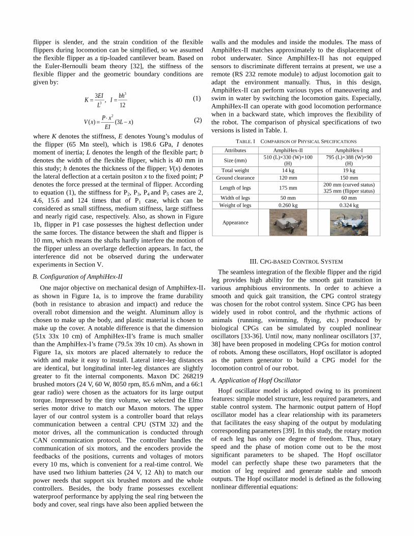
where K denotes the stiffness, E denotes Young’s modulus of the flipper (65 Mn steel), which is 198.6 GPa, I denotes moment of inertia; L denotes the length of the flexible part; b denotes the width of the flexible flipper, which is 40 mm in this study; h denotes the thickness of the flipper; V(x) denotes the lateral deflection at a certain positon x to the fixed point; P denotes the force pressed at the terminal of flipper. According to equation (1), the stiffness for P2, P3, P4 and P5 cases are 2, 4.6, 15.6 and 124 times that of P1 case, which can be considered as small stiffness, medium stiffness, large stiffness and nearly rigid case, respectively. Also, as shown in Figure 1b, flipper in P1 case possesses the highest deflection under the same forces. The distance between the shaft and flipper is 10 mm, which means the shafts hardly interfere the motion of the flipper unless an overlarge deflection appears. In fact, the interference did not be observed during the underwater experiments in Section V.
B. Configuration of AmphiHex-II One major objective on mechanical design of AmphiHex-II,
as shown in Figure 1a, is to improve the frame durability (both in resistance to abrasion and impact) and reduce the overall robot dimension and the weight. Aluminum alloy is chosen to make up the body, and plastic material is chosen to make up the cover. A notable difference is that the dimension (51x 33x 10 cm) of AmphiHex-II’s frame is much smaller than the AmphiHex-I’s frame (79.5x 39x 10 cm). As shown in Figure 1a, six motors are placed alternately to reduce the width and make it easy to install. Lateral inter-leg distances are identical, but longitudinal inter-leg distances are slightly greater to fit the internal components. Maxon DC 268219 brushed motors (24 V, 60 W, 8050 rpm, 85.6 mNm, and a 66:1 gear radio) were chosen as the actuators for its large output torque. Impressed by the tiny volume, we selected the Elmo series motor drive to match our Maxon motors. The upper layer of our control system is a controller board that relays communication between a central CPU (STM 32) and the motor drives, all the communication is conducted through CAN communication protocol. The controller handles the communication of six motors, and the encoders provide the feedbacks of the positions, currents and voltages of motors every 10 ms, which is convenient for a real-time control. We have used two lithium batteries (24 V, 12 Ah) to match our power needs that support six brushed motors and the whole controllers. Besides, the body frame possesses excellent waterproof performance by applying the seal ring between the body and cover, seal rings have also been applied between the
walls and the modules and inside the modules. The mass of AmphiHex-II matches approximately to the displacement of robot underwater. Since AmphiHex-II has not equipped sensors to discriminate different terrains at present, we use a remote (RS 232 remote module) to adjust locomotion gait to adapt the environment manually. Thus, in this design, AmphiHex-II can perform various types of maneuvering and swim in water by switching the locomotion gaits. Especially, AmphiHex-II can operate with good locomotion performance when in a backward state, which improves the flexibility of the robot. The comparison of physical specifications of two versions is listed in Table. I.
TABLE. I COMPARISON OF PHYSICAL SPECIFICATIONS Attributes AmphiHex-II AmphiHex-I
Size (mm) 510 (L)×330 (W)×100 (H)
795 (L)×388 (W)×90 (H)
Total weight 14 kg 19 kg Ground clearance 120 mm 150 mm
Length of legs 175 mm 200 mm (curved status) 325 mm (flipper status)
Width of legs 50 mm 60 mm Weight of legs 0.260 kg 0.324 kg
Appearance
III. CPG-BASED CONTROL SYSTEM The seamless integration of the flexible flipper and the rigid
leg provides high ability for the smooth gait transition in various amphibious environments. In order to achieve a smooth and quick gait transition, the CPG control strategy was chosen for the robot control system. Since CPG has been widely used in robot control, and the rhythmic actions of animals (running, swimming, flying, etc.) produced by biological CPGs can be simulated by coupled nonlinear oscillators [33-36]. Until now, many nonlinear oscillators [37, 38] have been proposed in modeling CPGs for motion control of robots. Among these oscillators, Hopf oscillator is adopted as the pattern generator to build a CPG model for the locomotion control of our robot.
A. Application of Hopf Oscillator Hopf oscillator model is adopted owing to its prominent
features: simple model structure, less required parameters, and stable control system. The harmonic output pattern of Hopf oscillator model has a clear relationship with its parameters that facilitates the easy shaping of the output by modulating corresponding parameters [39]. In this study, the rotary motion of each leg has only one degree of freedom. Thus, rotary speed and the phase of motion come out to be the most significant parameters to be shaped. The Hopf oscillator model can perfectly shape these two parameters that the motion of leg required and generate stable and smooth outputs. The Hopf oscillator model is defined as the following nonlinear differential equations:

( )( )
2 2 2,
2 2 2,
2( )
2
i i i u ii i i
v ii i
i
i i
k A u v u fv cX F X C
ck A u v v fu
π
π
− − − = + = + − − +
& (3)
where F(Xi) denotes a nonlinear system defined by Hopf oscillator, Xi =[ui, vi]T denotes the state vector of the i th system, and ui is selected as the output in this paper; Ci =[cu,i, cv,i]T denotes the coupling vector; k denotes a positive constant of the speed of convergence; f denotes the oscillator frequency; And A denotes the amplitude of the steady state oscillation.
Multiple coupled oscillators have been adopted to achieve a fast and stable convergence. In the final control system, we define parameter φi,j to represent the preset phase difference between two mutual coupling oscillators, such as oscillator i-1 and oscillator i. Multiple couplings imposed on one oscillator can be achieved by a linear combination of other coupling terms. Thus, the state vector of the i th Hopf oscillator (Xi) using the multiple coupling way can be expressed by:
2 2 2
2 2 2
1 1, 1 1, , 1 1 , 1
( ) 2( ) 2
0( sin cos sin cos )
i i i i ii
i i i i i
i i i i i i i i i i i i
u k A u v u fvX
v k A u v v fu
u v u v
ππ
ε ϕ ϕ ϕ ϕ− − − − + + +
− − − = = − − +
+ + − +
&&& (4)
where φi,j is defined as a desired value in different gaits’ generation; ε denotes the constant regulating the strength of coupling of the phase difference.
B. Analysis and Settings of CPG Parameters In order to achieve a stable CPG control system with fast
convergence, we need to know the exact influence of each parameter on the oscillator’s motion. So we have carried out series of online simulations to obtain the results.
We can draw some conclusions from the results we have obtained. Firstly, the prior property of Hopf oscillator is its limit cycle behavior [39]. Although we have set four different evolution starts that represent different initial statuses of robot deliberately, lines of four states always converge to a limit cycle with radius A as time increases. This means the motion of robot will not necessarily return to the initial status when the system restarts a new locomotion gait as a result of the limited cycle behavior. Secondly, a larger value of k leads to faster convergence of system. The time consumption of convergence accounts for 1/12 period when the value of k is 20, which totally meets the requirement of a rapid convergence and leaves enough time for system (motors etc.) response. So there is no need to further increase the value. Thirdly, the value of A only decides the amplitude of outputs, so the value of A is set as a constant of 1 in this study. Locomotion speed of the robot is decided by frequency f, through changing its value, different locomotion speed can be achieved. Finally, another significant parameter φ should be demonstrated. When φi,j=0, two oscillators keep a synchronous phase; if φi,j≠0, two oscillators keep an asynchronous phase, especially when φi,j=π or -π, two oscillators keep an opposite phase. By changing values of φi,j, a variety of combinations of oscillator statuses can be achieved, which is the basis of gait generation and transition
of robot with CPG control system [7, 8], [39]. We set the parameters in our finally control system as follows: k=20, A=1, and ε=0.8, values of f and φi,j depend on the gait. Final CPG control system with such parameter setting is robust, although we change the value of parameters of oscillators (which can be assumed as a perturbation to the control system), it can still smoothly, continuously and quickly transit to a new stable state.
C. CPG-based Control Structure of AmphiHex-II AmphiHex-II is driven by six motors, so six oscillators are
required to generate the locomotion gaits for six legs. As we know, coupling connections between oscillators determine the CPG model. In order to achieve a fast transition performance, we adopt the mutual coupling method, although it requires a higher computational cost. Also, we need to decide the structure of CPGs. When more oscillators are involved, there exist some topological structures of CPGs, which include the chain type, the ring type, the radial type, the fully connected type and even the combinations of several types aforementioned [40-44]. To achieve a complete mutual coupling of six oscillators simply and effectively, a combination of chain type and radial type is chosen in our final CPG control structure as shown in Figure 2.
Figure 2. CPG-based motion control structure of AmphiHex-II.
We can see from Figure 2 that oscillator 1 to 6 correspond to Leg 1 to 6, respectively. Six oscillators are divided into three groups: the front group, the middle group and the rear group. On each side, three oscillators are used to control one side legs, and the oscillators are coupled with the front one with the radial type. Each side can be controlled independently, and only oscillators in the same group have mutual couplings. Besides, an initial zero phase of each oscillator is set to achieve a synchronous start. The locomotion control for left side motion of legs can be expressed as follows:
( ) , 1, 2,3i iy t u i= = (5)
1 1
4
0( )X F X
vε
= +
& (6)
1 1, 1 1,
0( ) , 2,3
sin cosi ii i
X F X iu v
εϕ ϕ
= + = +
& (7)
where i denotes the serial number of oscillator, and yi(t) denotes the output control signals ui for three legs of the left side. The equations that express the control for right side are in a similar form.

IV. GAIT GENERATION AND TRANSITION OF AMPHIHEX-II In this section, we will introduce the CPG based control
method in gait generation and transition. Different strategies in terrestrial and underwater gait generation are also described.
A. Relationship between CPG Outputs and Leg Motions Before introducing the gait generation strategies,
relationship between outputs of oscillators and control signals of motors needs to be demonstrated. Firstly, we have presented the relationship of CPG signals and leg motion on land and underwater. As shown in Figure 3a, if the leg turns clockwise on land, first P touches the ground and Q refers to the lift-off. So the rotational circle has been divided into two phase components: the swing phase (θ1) and the support phase (θ2). As demonstrated in Section II, the angle α of fan-shaped frame is 60° and the motion from P to Q is a rolling process, so we can obtain that θ2 is 90°. Since time consumption of these two phases are both T/2, in order to achieve a continuous motion, the rotational speed of leg in the swing phase requires to be set three times as the speed in the support phase. When the robot is swimming underwater, the legs propel like fish flipper. As shown in Figure 3b, the swing process can also be divided into two components: the up-stroke process and down-stroke process. In this case, the angle of θd denotes the swing amplitude which is set 30° in this study, and Φ denotes the offset phase that represents the start position of legs in different gaits underwater. Point M and N denote two boundary positions of the up-stroke and down-stroke, respectively.
Figure 3. Relationship of CPG signal and leg motion on land and underwater (a) Phase components of one locomotion period on land. ‘SW’ denotes the swing phase and ‘SUP’ denotes the support phase; (b) Phase components of one locomotion period underwater. ‘US’ denotes the up-stroke process and ‘DS’ denotes the down-stroke process.
As described in Section III, the whole control system is a nonlinear system, the outputs of CPG are sinusoidal signals. While the locomotion modes of terrestrial and underwater locomotion are different, legs should conduct rotary motions to achieve terrestrial locomotion and oscillating motions to achieve underwater locomotion. So it is essential to establish the relationship between the CPG outputs ui and the control signals of motors on land Li(t) and underwater Wi(t), in which i denotes the serial number of oscillator and the corresponding motor. As shown in Figure 3a, the rising edge of the output
signals wave of oscillator corresponds to the support phase and the declining edge corresponds to the swing phase when AmphiHex-II is walking on land [45]. The crest and the trough of the signals denote the position marked by Q and P, respectively. And we set point P as the start position of Li(t), which enables six legs to contact with the ground when the robot is ready for terrestrial locomotion, the relationship of ui and Li(t) can be defined as equation (8). Similarly, as shown in Figure 3b, the rising edge of the wave corresponds to up-stroke process and the declining edge corresponds to down-stroke process when AmphiHex-II is swimming underwater. The crest and the trough of the wave denote the position marked by M and N. Since the oscillating amplitude is 30°, the relationship of ui and Wi(t) can be defined as equation (9). Thus, the relationship between CPG outputs and motors has been established. Two equations are presented as follow:
(1 ) 0
4 2( )32 - (1 ),4 2
i
ii
u TtAL t
u T t TA
π
ππ
+ ≤ <= + ≤ ≤
, (8)
( ) + 06
ii
uW t t TA
π= Φ ⋅ ≤ ≤, (9)
B. Gait Generation in Various Environments Before conducting a locomotion, six legs should be ready at
a certain position. For all terrestrial locomotion, point P illustrated in Figure 3a is the start position, as for the aquatic locomotion, the start position is decided by phase Φ in different gaits. Parameters φi,j and Φ decide the locomotion gait, and f decides the locomotion speed.
We can establish a matrix expression to describe the phase setting of a terrestrial locomotion gait. Due to limited space of this paper, we only take the expression of tripod gait for example,which can be defined as follow: (where ‘*’ denotes the undefined values)
,
6 6
* 0 0* * * * * ** * * * * *- 0 - * - 0* * * * * ** * * * * *
i j
π π π
ϕπ π π
×
=
(10)
It is seen from the matrix that Oscillators 1, 3 and 5 possess the same phase, Oscillators 2, 4 and 6 possess the same phase, while phases of these two groups are opposite. When outputs of Oscillators 1, 3, and 5 are in the rising edge, the outputs of Oscillators 2, 4, and 6 are in the declining edge. Thus, according to the relationship of CPG outputs and locomotion phase shown in Figure 3, we can imagine that while one tripod formed by Legs 1, 3 and 5 are rotating in support phase, the other three legs (Legs 2, 4 and 6) are in swing phase rotating rapidly to be ready for the next support phase, which is exactly the tripod gait. Besides the tripod gait, tetrapod gait and hexapod gait will be adopted when the robot needs to cross over the obstacles (such as the stairs) and passing through specific terrains like muddy terrains which require a

large output of torque. Similar to the tripod gait, we can easily get the phase difference expressions of tetrapod gait and hexapod gait.
When the robot is propelling underwater, swimming gaits correspond to a combination of fixed initial phase offset Φ and different oscillating motions of flippers. Distinctive offset phase Φ for various underwater locomotion gaits are presented as follow:
Backward
3 / 2, =1,2,3,4,5,6/ 2, =1,2,3,4,5,6
/ 2, =1,2,3;3 / 2, =4,5,6/ 4, 2,5;7 / 4, =1,3,4,6
3 / 4, 2,5;5 / 4, =1,3,4,6
Cruising
Turning
Diving
Surfacing
ii
i ii ii i
ππ
π ππ ππ π
Φ Φ ΦΦ = = Φ = Φ =
(11)
where i denotes the serial number of legs. And we only define the right turning case in the expression, the definition of left turning case is opposite. Φ decides the difference of various underwater locomotion gaits. It’s notable that two middle legs oscillate oppositely to the four corner legs (which means φ2,5=0, φ2,j=π, j=1, 3, 4, 6) in these underwater gaits. This setting can considerably reduce the amounts of pitch, roll, and yaw during the cruising and backward swimming processes, and enables the robot to achieve vertical diving and surfacing processes, as shown in Figure 10. With above descriptions, all the gaits both on terrains and underwater can be generated.
C. Gait Transition with the Application of CPG The smooth transition process among different gaits is the
primary contribution of CPGs. By changing the frequency f, the locomotion speed can be changed. Smooth transition among various gaits ensures no jerk or discontinuity in the locomotion, which can benefit the locomotion performance.
Through changing the phase difference φi,j, and offset phase Φ, the locomotion gait can be changed, all the gait transition processes are based on this principle. Here we take a typical gait transition processes for example: the transition from hexapod to tripod gait. Figure 4 shows the variation of CPG output signals during the transition process. The blue colored signals denote the control signals of the tripod formed by Leg 1, 3 and 5, red colored signals donate the control signals of the tripod formed by Leg 2, 4 and 6. Two changes happened at 8 and 16 s, respectively. This figure illustrates a process that AmphiHex-II starts with a slow hexapod gait (f=0.5 Hz), then transits to slow tripod gait and finally accelerates to fast tripod gait (f=1 Hz). Signals in 0~8 s illustrate the slow hexapod gait, signals in 8~16 s illustrate the slow tripod gait, and signals in 16~20 s illustrate the fast tripod gait. When φ1,2, φ1,4 and φ1,6 have been changed to π, Leg 1, 3 and 5 rotate gradually to achieve an opposite phase to Leg 2, 4 and 6 to form a tripod gait. The whole transition process sustains about 2 periods, and if the locomotion speed is higher, time consumption of this gait transition will be reduced. We can also see from the figure, both the gait transition process and the accelerating process are smooth thanks to the properties of CPG emulated with non-linear oscillators.
Figure 4. Variation of CPG output signals during gait transition. Black dot lines in this figure illustrate the start and the end of the transition process.
V. EXPERIMENTAL RESULTS
To evaluate the locomotion performance of AmphiHex-II with variable stiffness legs, series of experiments have been conducted. These experiments cover following aspects: (1) locomotion performance of AmphiHex-II with variable stiffness legs on flat ground and underwater, where the performance is measured in terms of the locomotion speed; (2) the ability of AmphiHex-II to adapt various terrains and cross over obstacles; (3) various motions underwater.
A. Locomotion Performance of AmphiHex-II
Figure 5. Experiments to investigate the locomotion speed of AmphiHex-II on land and underwater. SH, ST, FH, FT denote the slow hexapod gait, slow tripod gait, fast hexapod gait and fast tripod gait, respectively.
In the experiments, we have evaluated the walking performance of AmphiHex-II with two typical walking gaits and swimming performance with flippers of different stiffness, and compared the results to the highest speed that achieved by AmphiHex-I with the same parameter conditions in two cases. Measuring approach and the parameter settings are also presented in Figure 5 (the scale of the soft measuring belt is 5 cm).
We can see from the bars in the figure that the highest speed of AmphiHex-II with fast tripod gait is 0.36 m/s, which is almost twice as the highest speed (0.20 m/s) achieved by AmphiHex-I with 1 Hz cycling frequency and battery drive [46]. When walking at higher frequencies, AmphiHex-II’s performance is better, since the rigid fan-shape leg frame

reduces the whole compliance compared to the previous flexible flipper legs of AmphiHex-I and works as offset wheels. Whereas the motion of Amphihex-I with flexible flipper legs becomes irregular in higher frequencies cases. Another significant factor that leads to a better performance of the robot is the lighter weight of AmphiHex-II. Meanwhile, the standard deviation of speed is so small, which indicates the locomotion process is stable.
The investigation of the locomotion performance underwater has also been conducted. Oscillating motions of flippers in the water generate thrust force mainly, while the rigid leg frames generate limited thrust underwater. In this study, the oscillating amplitude is set 30°, and the frequency is set 2 Hz. Through series of experiments, we have obtained the physical swimming speeds of robot underwater, as shown in Figure 5. The highest speed underwater of AmphiHex-II is 0.37 bl/s, compared with the highest speed (0.19 bl/s) achieved by AmphiHex-I with 2 Hz oscillating frequency [47]. The reasons can be considered as following aspects: Although the leg length is shorter than previous version, proper stiffness of the new leg design can achieve higher thrust force in the water; there is no doubt that slimmer body of AmphiHex-II, which generates less dragging forces underwater, also contributes to the higher speed. Analyzing the data, we can also draw a primary conclusion that the locomotion speed underwater can be improved by enhancing the stiffness of flipper, which is conformed to our former study results [46]. Compared with some latest generation of robots, such as Salamander-II [48], RHex, and AmphiRobot-II [10], locomotion performance of AmphiHex-II is comparable. The highest swimming speed underwater of Salamander-II and AmphiRobot-II are 0.44 bl/s and 0.64 bl/s, respectively. The RHex series are fast on land (0.6 m/s), but their semi-circular legs can generate limited thrust underwater. However, the seamless integration of variable stiffness flippers and leg frames of AmphiHex II provides a smooth transition ability in amphibious environments.
B. Locomotion Gaits on Various Terrains
AmphiHex-II with variable stiffness legs has also been evaluated for achieving various gaits and walking on different kinds of terrains including ground, grass, sand, mud, slope, stairs and complex amphibious areas.
Figure 6. Snapshots of AmphiHex-II conducting a 90° right turning. Arrows show the rotational direction of each leg. Z denotes the vertical direction, X1
and X2 denote the initial and final heading direction.
As mentioned earlier, robots with semi-circular legs usually cannot conduct turning motion easily because semi-circular legs are always not effective in the counter-rotate case. While
thanks to the unique design of the legs and application of CPGs, AmphiHex-II can achieve turning motions on the spot quickly and smoothly. Figure 6 presents the image sequences of the right turning motion on the ground. As shown in the Figure 6, six legs can be divided into two groups, group one contains leg L2, leg R1 and leg R3, the rest three legs make up group two. Similar to the tripod gait, while the tripod formed by one group of legs is in contact with ground, the other group of legs are rotating rapidly to be ready for the next motion. Differently, during the turning process, leg L2 (R2) carries the opposite rotatory motion to the leg R1 and R3 (L1 and L3) to generate the steering force. In such a circulatory motion, robot can achieve a rapid turning in situ. The whole turning process is within 2 periods.
(a) (b)
Figure 7. (a) Snapshots of AmphiHex-II in climbing slope and stairs with climbing gait and tetrapod gait. The gradient of these two terrains is 30° and 20°, respectively. We tethered the robot in order to protect it when unexpected overturn occurs during stairs climbing. (b) Analysis of the stability in climbing slope with different support phases.
We have also evaluated the ability of AmphiHex-II in climbing the slope and stairs, and the image sequences are presented in Figure 7a. Climbing gait is adopted in climbing a slope. Climbing gait is based on the tripod gait. Differently, the support phase of climbing gait is 2/3 of the support phase of the normal tripod gait. Here we explain how the support phase influences the locomotion stability during climbing slope. When the robot climbs up a slope, as shown in Figure 7b, the effective supporting area for robot is a triangular area. Triangle a-b-c or a’-b’-c’ denotes the supporting area when three legs first touch the slope and triangle A-B-C or A’-B’-C’ denotes the supporting area when three legs lift off. In Figure 7b, gait with a large support phase is easy to be unstable because the CG is out of the overlapping area during propelling process. After reducing the support phase, AmphiHex-II can keep a stable locomotion in upslope process. While in climbing stairs cases, tetrapod gait is adopted. In tetrapod gait, left legs and right legs of three groups are synchronous. When one group of legs are circulating rapidly to be ready for the next support, four legs of the other two groups are in support status thus AmphiHex-II can climb up stairs with good stability. The maximum height of a single stair that AmphiHex-II can climb up is 18 cm, which is twice as much as the height of AmphiHex-II. This also indicates the capability of AmphiHex-II in crossing over normal obstacles.

Figure 8. AmphiHex-II propelling in various terrains. (a) Soil terrain; (b) Muddy substrate; (c) Amount of mud sticking on the leg at P1 and P5 cases, yellow lines present the position and status of flipper.; (d) Sandy terrain; (e) Grassland. (f) Different pushed areas of rigid and flexible flipper.
Propelling in soft terrains, such as grassy, sandy, soil and muddy terrains, is also a kind of a challenging task for amphibious robot. As mentioned earlier, the slender fan-shape leg makes it easy to dig into the terrains, and the supporting plate increases the contact area, so AmphiHex-II possesses the capability to propelling in soft terrains. Generally, flippers push away the soft medium, the reactive forces generated by the medium support and propel the robot, which benefits the locomotion performance. Especially, when the robot is propelling in sandy substrates, soft soil terrains and muddy terrains, the stiffness of flipper legs has a significant influence on the locomotion. Sandy substrates can be considered as a granular media with rheological characteristics, and behave like an elastic solid below a critical stress and a fluid above the critical stress. A higher stiffness flippers usually can generate a smaller thrust force to destroy the granular media easily. However, the case is more complicated when the robot is propelling in the muddy terrain. As shown in Figure 8b, the experiment was conducted in the muddy terrain with a 25% water content and two cases of the amount of sticking mud on the leg are presented in Figure 8c. We can see from the red frames in Figure 8c that flipper leg with smaller stiffness tends to carry more mud during the whole rotation period, which is inefficient. To conclude, the flexible flipper must be more compliant to reduce the resistance when the robot is propelling in grassy, sandy, soil terrains, so we can adjust the sliders to position 1 on the leg frame as described in Figure 1 to make the flexible flipper much more compliant. While in the sticky muddy terrain, flipper leg with less compliance is more effective for locomotion.
C. Launching and Landing Locomotion
Simple propulsion method while achieving good landing and launching motion is another highlight of AmphiHex-II. As shown in Figure 9.
Figure 9. Snapshots of AmphiHex-II conducting launching and landing motions; Statuses of flexible flipper in the transition terrain and underwater are presented in the right part. Area A, B, and C denote the pushed areas.
During launching and landing processes, there exist three kinds of terrains which are land, water, and the transition area with land and water, respectively. When propelling in the transition area, hexapod gait is usually adopted to ensure enough output torque to generate sufficient propulsive force. Whilst the combination of flexible flipper and rigid fan-shape leg allows the legs to generate propulsion in these three kinds of terrains, which makes it possible for AmphiHex-II to conduct launching and landing motion successfully without other complex control. Besides, in amphibious terrains, we need to consider the propulsion both in transition area and underwater. According to the results presented in Figure 5, when the robot swims underwater, flippers should be less compliant to generate larger thrust; when the robot passes through transition area, which is always slurry substrate, flippers should be more compliant to let the slurry flow through. Hence, we can adjust the slider to position 3 to achieve an appropriate compliance of legs to ensure the propulsion in both two terrains but not to increase the resistance fiercely when walking in the transition area. Statuses of flexible flipper in the transition terrain and underwater are also presented in Figure 9. Moreover, with the application of CPGs, the launching and landing process is also smooth and rapid, since the CPGs enables the robot to adapt a new locomotion gait continuously and quickly as mentioned before. We can see from the figures that robot is able to enter the water, swim out of water, and walking through the transition area successfully, which illustrates the legs are sufficient to perform these actively.
D. Swimming Underwater
As mentioned earlier, the flexible flippers play the major role in performing underwater movements with high maneuvering ability. Based on the obtained results in Figure.5, we can see that less compliance of flippers lead to higher propelling speed. Although this would require more energy consumption, what our focus is more on the physical speed that the robot can achieve with flipper legs. Thus, during swimming underwater, we should adjust six legs to be less compliant to achieve higher physical speed, so we can adjust the sliders to position 5 on the leg frame. As shown in Figure 10, AmphiHex-II is capable of achieving many maneuvers including turning, cruising, backward swimming, descending and ascending locomotion underwater by conducting different combinations of various directions and phases of the flipper legs propulsion.

Figure 10. AmphiHex-II maneuvering underwater. From picture (a) to (g), the figures correspond to cruising, backward swimming, turning gait, descending and ascending locomotion, respectively.
According to the presented analysis and discussions, the adoption of appropriate stiffness of flipper legs to adapt to a specific environment has been summarized in Table II. P2 can be an alternative for P1 case, and P4 can be an alternative for P5 case.
TABLE. II ADOPTION OF APPROPRIATE STIFFNESS
Environments Stiffness Adjustment Sand, grassland, soft soil Small P1 Amphibious environment (including water, transition areas and land) Medium P3
Aquatic environment and muddy substrates Rigid P5
Rough terrains No particular requirements
VI. CONCLUSION REMARKS AND FUTURE WORK
In this work, we proposed and evaluated the novel design of variable stiffness legs to be used for a CPG-based amphibious robot. These legs allow robot to conduct various amphibious operations: swimming, walking, passing through transition area or soft terrains and climbing over obstacles. And these legs provide swimming underwater on the surface and maneuverability underwater. We have also verified these legs are suitable for walking on a variety of terrains types by adjusting the stiffness. Except the versatility, achieving amphibious locomotion with only one set of propulsion mechanism and simple control strategy are highlights of this work. Thanks to the introduction of CPG, transition between various gaits are smooth and quick.
The adjustment of the variable stiffness legs to adapt to different environments is manually done in this study. Hence, driving mechanisms for the adjustment of the sliders, and more sensors will be applied in AmphiHex-II in the future to achieve autonomous and adaptive amphibious locomotion, which would also broaden the field applications of AmphiHex-II.
ACKNOWLEDGMENT
This research is supported by National Natural Science Foundation of China (No.51375468) and Australian Research Council (ARC) Discovery Grant (DP150102636).
REFERENCES [1] Galloway K C, Haynes G C, Ilhan B D, et al. X-RHex: A highly mobile hexapedal robot for sensorimotor tasks. 2010. [2] Dudek G, Giguere P, Prahacs C, Saunderson S. AQUA: An amphibious autonomous robot. Computer, 2007, 40, 46-53. [3] AQUA2 amphibious robot is super cute and fast, less annoying than most pets because it has no head, http://www.engadget.com/2010/07/08/aqua2-amphibious-robot-is-super-cute-and-fast-less-annoying-tha/. [4] Hirose S, Yamada H. Snake-Like robots machine design of biologically inspired robots. IEEE Robotics & Automation Magazine, 2009, 16, 88-98. [5] Wright C, Buchan A, Brown B, Geist J, Schwerin M, Rollinson D, Tesch M,Choset H. Design and architecture of the unified modular snake robot. Proceedings of the IEEE International Conference on Robotics and Automation, St.Paul, USA, 2012, 4347-4354.
[6] Matsuo T, Yokoyama T, Ueno D, Ishii K. Biomimetic motion control system based on a CPG for an amphibious multi-link mobile robot. Journal of Bionic Engineering, 2008, 5, 91-97. [7] Crespi A, Ijspeert A J. Online optimization of swimming and crawling in an amphibious snake robot. IEEE Transactions on Robotics, 2008, 24, 75-87. [8] Ijspeert A J, Crespi A, Ryczko D, Cabelguen J M. From swimming to walking with a salamander robot driven by a spinal cord model. Science, 2007, 315, 1416-1420. [9] Liwei Shi, Shuxiang Guo, Shilian Mao, Chunfeng Yue, Maoxun Li, Kinji Asaka. Development of an Amphibious Turtle-Inspired Spherical Mother Robot. Journal of Bionic Engineering, 2013, 10, 446-455. [10] Yu J, Ding R, Yang Q, Tan M, Wang W, Zhang J. On a bio-inspired amphibious robot capable of multimodal motion. IEEE/ASME Transactions on Mechatronics, 2012, 17, 1-10. [11] Boxerbaum A.S, Werk P, Quinn R D, Vaidyanathan R. Design of an autonomous amphibious robot for surf zone operation: Part I-Mechanical design for multi-mode mobility. Proceedings of the IEEE International Conference on Advanced Intelligent Mechatronics, Monterey, California, USA, 2005, 1459-1464. [12] Dey, Bir Bikram, Sandeep Manjanna, and Gregory Dudek. ‘Ninja legs’: Amphibious one degree of freedom robotic legs. IEEE/RSJ International Conference on Intelligent Robots and Systems. IEEE, 2013. [13] Linsen Xu, Tao Mei, Xianming Wei, Kai Cao, Mingzhou Luo. A Bio-Inspired Biped Water Running Robot Incorporating the Watt-I Planar Linkage Mechanism. Journal of Bionic Engineering, 2013, 10, 415-422. [14] Ayers J. Underwater Walking. Arthropod Structure & Development, 2004, 33, 347-360. [15] Carlson A, Papanikolopoulos N. Aquapod: Prototype design of an amphibious tumbling robot. Proceedings of the IEEE International Conference on Robotics and Automation, Shanghai, China, 2011, 4589-4594. [16] Kim H G, Lee D G, Jeong K M, et al. Water and ground-running robotic platform by repeated motion of six spherical footpads. IEEE/ASME Transactions on Mechatronics, 2016, 21(1): 175-183. [17] Kim H G, Sitti M, Seo T W. Tail-Assisted Mobility and Stability Enhancement in Yaw/Pitch Motions of a Water-Running Robot. IEEE/ASME Transactions on Mechatronics, 2017. [18] Li M, Guo S, Hirata H. A roller-skating/walking mode-based amphibious robot. Robotics and Computer-Integrated Manufacturing, 2017, 44: 17-29. [19] Saranli U, Buehler M, Koditschek D E. RHex: A simple and highly mobile hexapod robot. The International Journal of Robotics Research, 2001, 20(7): 616-631. [20] Shiwu Zhang Xu Liang, Lichao Xu, Min Xu. Initial Development of a Novel Amphibious Robot with Transformable Fin-leg Composite Propulsion Mechanisms. Journal of Bionic Engineering, 2013, 10, 434-445. [21] Kim H G, Lee D G, Liu Y, et al. Hexapedal robotic platform for amphibious locomotion on ground and water surface. Journal of Bionic Engineering, 2016, 13(1): 39-47. [22] Kim S, Clark J E, Cutkosky M R. iSprawl: Design and tuning for high-speed autonomous open-loop running. The International Journal of Robotics Research, 2006, 25(9): 903-912. [23] Zhong G, Deng H, Xin G, et al. Dynamic hybrid control of a hexapod walking robot: Experimental verification. IEEE Transactions on Industrial Electronics, 2016, 63(8): 5001-5011. [24] Deng H, Xin G, Zhong G, et al. Gait and trajectory rolling planning and control of hexapod robots for disaster rescue applications. Robotics and Autonomous Systems, 2017, 95: 13-24. [25] Moore E Z, Campbell D, Grimminger F, et al. Reliable stair climbing in the simple hexapod 'RHex'. Robotics and Automation, 2002, 3, 2222-2227. [26] Aydın Y O, Galloway K C, Yazicioglu Y, et al. Modeling the compliance of a variable stiffness C-shaped leg using Castigliano’s theorem. ASME International Design Engineering Technical Conferences and Computers and Information in Engineering Conference. American Society of Mechanical Engineers, 2010: 705-713. [27] Harper K A, Berkemeier M D, Grace S. Modeling the dynamics of spring-driven oscillating-foil propulsion. IEEE Journal of Oceanic Engineering, 1998, 23(3): 285-296. [28] Ziwen Kong, Min Xu, Xudong Wang, Youcheng Zhou, Shiwu Zhang. Gait planning and Gait transition of AmphiHex-I. Proceedings of the IEEE International Conference on Advanced Intelligent Mechatronics, 2014, 66-71. [29] Liang X, Xu M, Xu L, Liu P, Ren X, Kong Z, Yang J, Zhang S. The AmphiHex: a novel amphibious robot with transformable leg-flipper composite propulsion mechanism. Proceedings of the IEEE International
Conference on Intelligent Robots and Systems, Algarve, Portugal, 2012, 3667-3672. [30] Xiaoshuang Ren, Xu Liang, Ziwen Kong, Min Xu, Ronald Xu and Shiwu Zhang. An Experimental Study on the Locomotion Performance of Elliptic-curve Leg in Muddy Terrain. Proceedings of the IEEE International Conference on Advanced Intelligent Mechatronics. Wollongong, Australia, 2013, 518-523. [31] Xu L, Liang X, Xu M, Zhang S. Interplay of theory and experiment in analysis of the advantage of the novel semi-elliptical leg moving on loose soil. Proceedings of the IEEE International Conference on Advanced Intelligent Mechatronics. Wollongong, Australia, 2013, 26-31. [32] David M. Parks. Euler-Bernoulli Beams: Bending, Buckling, and Vibration. Mechanics and Materials, 2004. [33] Rosenberger L J. Pectoral fin locomotion in batoid fishes: undulation versus oscillation. Journal of Experimental Biology, 2001, 204(2): 379-394. [34] Toda Y, Danno M, Sasajima K. Model experiments on the squid-like under-water vehicle with two undulating side fins. Proceedings of the 4th International Symposium on Aero Aqua Bio-Mechanisms. 2009. [35] A. J. Ijspeert, A. Crespi, D. Ryczko, and J. M. Cabelguen. From swim-ming to walking with a salamander robot driven by a spinal cord model, Science, 2007, vol. 315, 1416–1420. [36] Zhong G, Chen L, Jiao Z, et al. Locomotion Control and Gait Planning of a Novel Hexapod Robot Using Biomimetic Neurons. IEEE Transactions on Control Systems Technology, 2017. [37] Matsuoka K. Sustained oscillations generated by mutually inhibiting neurons with adaptation. Biological cybernetics, 1985, 52(6): 367-376. [38] Zhao W, Yu J, Fang Y, et al. Development of multi-mode biomimetic robotic fish based on central pattern generator. Proceedings of the IEEE Intelligent Robots and Systems, 2006: 3891-3896. [39] Chunlin Zhou, K. H. Low, Design and Locomotion Control of a Biomimetic Underwater Vehicle with Fin Propulsion. IEEE/ASME Transaction on Mechatronics, vol. 17, No.1, 2012. [40] Buchli J, Ijspeert A J. Distributed central pattern generator model for robotics application based on phase sensitivity analysis. International Workshop on Biologically Inspired Approaches to Advanced Information Technology. Springer Berlin Heidelberg, 2004: 333-349. [41] Zhou C, Low K H. Kinematic modeling framework for biomimetic undulatory fin motion based on coupled nonlinear oscillators. Intelligent Robots and Systems (IROS), 2010 IEEE/RSJ International Conference on. IEEE, 2010: 934-939. [42] D. Zhang, D. Hu, L. Shen, and H. Xie. Design of an artificial bionic neural network to control fish-robot’s locomotion, Neuro Computing, vol. 71, pp. 648–654, 2008. [43] Kassim A B M, Yasuno T. Moving control of quadruped hopping robot using adaptive CPG networks. Robotics Automation and Mechatronics (RAM), 2010 IEEE Conference on. IEEE, 2010: 581-588. [44] Dalla Libera F, Minato T, Ishiguro H, et al. Direct programming of a central pattern generator for periodic motions by touching. Robotics and Autonomous Systems, 2010, 58(7): 847-854. [45] Zhou Y, Zhong B, et al. Application of bio-inspired control of AmphiHex-I in detection of Oncomelania hupensis, the amphibious snail intermediate host of Schistosoma japonicum. Industrial Robot, 2017, 44(2): 242-250. [46] Zhong B, Zhou Y, Li X, et al. Locomotion Performance of the Amphibious Robot on Various Terrains and Underwater with Flexible Flipper Legs. Journal of Bionic Engineering, 2016, 13(4): 525-536. [47] Zhang S, Zhou Y, Xu M, et al. AmphiHex-I: Locomotory Performance in Amphibious Environments with Specially Designed Transformable Flipper Legs. IEEE/ASME Transactions on Mechatronics, 2015, 21(3):1-1. [48] Crespi A, Karakasiliotis K, Guignard A, et al. Salamandra robotica II: an amphibious robot to study salamander-like swimming and walking gaits. IEEE Transactions on Robotics, 2013, 29(2): 308-320.