on designing underwater camera lenses
TRANSCRIPT
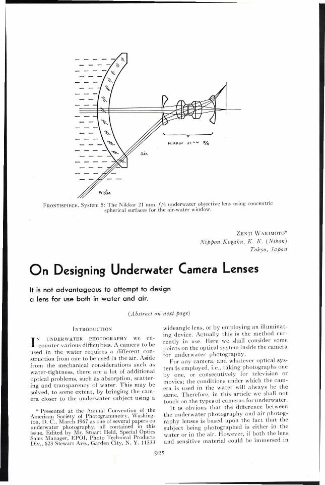
FRONTlSP1ECE. System 5: The .Nikkor 21 mm. J/4 u.nderwater objective lens using concentricphencal surfaces for the aIr-water window.
ZE:" Jl \\1 AKIMOTO*
Nippon Kogaku, K. K. (Nikon)Tokyo, Japan
On Designing Underwater Camera Lenses
It is not advantageous to attempt to designa lens for use both in water and air.
(Abstract on next page)
925
INTRODUCTION
I N NDERWATER PHOTOGRAPHY we encounter various difficulties. A camera to be
used in the water requires a different construction from one to be used in the air. Asidefrom the mechanical considerations such aswater-tightness, there are a lot of additional?ptical problems, such as absorption, scatterIng and transparency of water. This may besolved, to some extent, by bringing the camera closer to the underwater subject using a
* Presented at the Annual Convention of theAmerican Society of Photogrammetry, Washington, D. c., March 1967 as one of several papers onunderwater photography, all contained in thisissue. Edited by Mr. Stuart Held, Special OpticsSales Manager, EPOI, Photo Technical ProductsDiv., 623 Stewart Ave., Garden City, N. Y. 11533
wideangle lens, or by employing an illuminating device. Actually this is the method currently in use. Here we shall consider somepoints on the optical system inside the camerafor underwater photography.
For any camera, and whatever optical system is employed, i.e., taking photographs oneby one, or consecu ti vely for teleyision ormovies; the conditions under which the camera is used in the water will always be thesame. Therefore, in this article we shall nottouch on the types of cameras for underwater.
I t is obvious that the difference betweenthe underwater photography and air photography lenses is based upon the fact that thesubject being photographed is either in thewater or in the air. However, if both the lensand sensitive material could be immersed in

926 PHOTOGRAMMETRIC ENGINEERING
water, the problems ,,'ould be simplified.Thus, the refracti"e indices both in the subject and in the image area become the sameand we need only to consider the refractiveindex of air as replaced by that of water. Usually, a lens immersed in the water has aweaker refracting power than that in the air.and shows different aberrations. However, nosubstantial change will take place in the function of the lens. Therefore, any underwaterlens to be used this way needs only to be corrected the same way as lens for air photography. Several years ago, a trial com bi nationof an ordinary lens and light sensiti,'e material was made by the Konan Camera Institute
Although several studies have been published on the methods to eliminate the deterioration of the image due to water in the subject area, most of them have been made onlyon the basis of some fundamental and approximate formula. There are actually only afew exacting optical systems developed exclusively for underwater use.
It is a well known fact that in designing alens of excellent image characteristics; it isnecessary to carry ou t the so-called "opticalray tracing" method. In other words, theelemental arrangement of a lens system is notsufficient. In the last few years equipment forswim mi ng, picture taki ng, illu mi nation, etc,
A RSTRACT: .11any types of lenses have been designed for photographic use understandard atmospheric conditions, but only very few lenses have been buill exclusively for underwater photograph)'. In many cases those that have been designedfor standard use are applicable to underwater photography without any alteration. The Nippon firm is the manufacturers of the lenses for our underwatercamera NIKONOS. These lenses have remarkable differences in characteristicsfrom atmospheric photographic lenses. In designing such lenses, the d~fferences
to be considered were theoretically examined and all the conceivable types ofunderwater lenses were systematically class~fied, Several examples of the underwater lenses are in current manufacture, and some interesting types of lenses canbe expected in the future.
for underwater photography, where neitherwater-proofing nor water pressure was considered. The construction was extremely simple.The institute realized that even though thefilm is immersed in seawater for several days,the film is usable enough for making a pictureafter it is washed with fresh water and developed. However. this is an exceptional case,
In general, the underwater camera is supplied with a piece of window glass or the likefor water-tightness and is designed so as toproduce an image in the air contained withinthe camera. Then, the refraction of light takesplace at the boundary surface between thewater and the air, thus giving rise to variousproblems. Therefore in designing a lens system the difference of refractive index betweenthe subject and image area should be considered. As an example, the oil-immersion objecti,'e lens for a microscope, Until now, formost underwater lenses, owing to manydifficulties encountered in taking a picture, nogreat importance has been placed on the image characteristics. I n most cases, in underwater photography, the lens designed for airphotography is applied without any alteration,
has undergone a marked developmen t,whereas the lens for underwater photographyhas been neglected.
We have closely studied the problems ofdeveloping proper underwater lenses. Belowwe shall discuss some problems and suggestdifferent types of lenses for underwaterphotography, based on our experience in designing underwater lens systems which willperform as satisfactorily as the lens systemsfor air photography.
PROllLEM 0:-< UNDERWATER LENSES
Looking at a subject in the water fromabo"e through the air, it appears as if the su bject were closer to the surface of the waterthan it actually is, If we observe it slantwiseto the surface of water, the edge of the subjectin the water is accompanied by color fringes.This is attribu ted to the fact that the ligh tcoming from the subject undergoes refractionas well as color dispersion at the boundarysurface between water and air. To such aphenomenon, the law of refraction is applied,whereby the refracting angle Oa as against thenormal angle is always larger than the incidence angle Ow in the water.

ON DESIGNING UNDERWATER CAMERA LENSES 927
Furthermore, this refracting angle, \'aryingwith the wavelength (color) of light, bringsabout color dispersion (Figure 1).
If the picture of a subject in water is taken,using a photographic lens which is well corrected for use in the air, the subject \\·ill be reproduced as a photograph. the same as seenby the eye.
If a distorted and colored image of the subject as seen by the eye were to be taken asreal, nothing would be said about the underwater lens. Problems arise though in the factthat the image of the subject the eye sees isnot the same as the actual image of the subject. The first problem is that the Rat surfaceappears as a cun'ed one and distorted in itsshape. I n order that the subject)' and its image y' are in an analogous relation to eachother, the dimensional ratio is to be constantbetween them. This means that it is necessaryto fulfill the following equation (Figure 2):
y' tan 0'-- = c--- = Conslanty tan 0
However, according to the law of refraction,as (sin O'/sin 0) is equal to nw and constant,(tan 0' /tan 0) is not constan t, bu t will bedifferent depending on the value of O.
For this reason, the larger the incidenceangle 0, the more distorted the image. For onewho stands on the edge of a swimming pooland obsen'es the Rat bottom of the pool, thefarther the subject, the closer the subject will
D
- _ - _-_wo!f:t-
FIG. 1. Optical refraction is accompaniedby color dispersion.
_7lYI __
FIG. 2. The law of refraction.
seem to approach the water surface and bemore distorted. This, if taken photographically, will show a different form from theactual one on the figure, caused by the lensaberrations, the so-called distortion and thecun'ature of the image plane.
The second problem is the occurrence ofcolor fringes on the edge of the image of thesubject caused by the di persion of light. Incolor photography the fringes result in coloredsmudges which appear more markedly on theedge of the image. As the image locates farther from the center of the picture, a redcolored smudge on the inside and a bluecolored smudge on the outside \\·ill appear. [nblack-and-white photography, the outline ofthe image will be blurred to an extent of the\\"id th of the color fri nges. From the viewpoint of lens design this occurrence corresponds to the chromatic aberrations whichproduce the same result as using a lens withits color aberrations not corrected, which is anunfavorable condition causing a lowering ofthe resolution in the photograph. The actualsubject has no such color fringe.
The third problem is concerned wi th thefact that even using a wide-angle lens, theunden\'ater picture area cO\'ered by this lensis narrowed to a noticeable degree, and theangular field of the lens is restricted. This \\·illbe easily understood if \\'e consider the refracting angle in the air which becomes largerthan the incidence angle in the water according to the law of refraction.
In practice, however, this problem is quitea di fficul t one to soh·e. As men tioned pre\'iously, as the transparency of \\'ater is not always good, it will be necessary to use artificialillumination at a great depth, or one must approach the subject as closely as possible. However, to come closer to the subject withoutnarro\\"ing the picture area, a lens ha\'ing afield angle as wide as possible is necessary.

928 PHOTOGRAMMETRIC El GINEERING
AirIn: 1.0)
FIG. 3. Convergent rays at various angles afterrefraction do not intersect at a common point.
Actually, wide-angle lenses are desirable foruse in underwater photography.
On the other hand, we must remember thatthe wider the field angle of the lens, the moremarked will be chromatic aberrations, distortion, and image plane curvature. This willcause much more deterioration of the picturequality. Frequently we encounter underwaterpictures in which the image quality is somewhat poorer at the circumference of the picture than at the center.
If we apply a lens designed for air photography to underwater use, some deteriorationof the image unavoidably takes place.
ANALYSIS OF THE ABERRATIONS CAUSED
BY THE WATER-AIR SURFACE
Until now, geometrical optical analysis ofsuch problems as above were often made, andmany papers on the solutions have been published. Among these papers is one by Prof.Alexandre Ivanoff in Revue D'optiquet, whichis excellent. However, like many other papers,it treats merely the analysis on the basis ofthe elemental formulas of geometrical opticsin the paraxial region. It is obvious that, inpractice, it does not suffice to examine the lenssystem only in the Gaussian region.
Furthermore, as far as a wide-angle lens isconcerned, the Seidel's region is still insufficient. If we consider the present situation wheremost lenses, including photographic lenses,are generally designed through ray tracing,the lens for underwater photography cannotbe an exception. In fact the lens, if used underwater, will give rise to extremely largeaberrations at the boundary surface betweenwater and air, and the light bundle converging to a point in the water will not performthe same as in air. See drawing as shown in(Figure 3). This shows how the optical theoryis imperfect so far as it stands only on the as-
sumption that the light bundle can convergeto a point on the basis of the elementary formulas.
Therefore, we should analyze the problemsconcerning the occurrence of such aberrationson the boundary surface between water andair with the aid of the regular designingmethod for optical systems.
I n general, the lens for underwater use, hasa plane-parallel glass window in front. Takingthe refractive indices of water, glass, and airas n"" ng and na , respectively, and their incidence angles of light rays against the normalas Ow, Og, and Oa, respectively, the followingequation will be obtained according to the lawof refraction (See Figure 4):
n wsin IJw = no sin lJo = n. sin IJ.. (.1)
Therefore, the resul t will be the same as thecase where water and air come into direct contact without any intermediate glasslayer. In fact, as long as the subject is at theinfinity distance, the presence of a glass hasno influence to the aberrations. Even thoughthe subject is at a finite distance, as long as itis relatively far distant, and the thickness ofglass is thin in relation to the distance, theglass can be neglected. Even though a filter isattached to an air lens, the change of the image characteristics may be practically neglected. Of course, if necessary we can correctthe aberrations taking into consideration thethickness of glass by ray tracing.
To simplify the problems, we assume thatthe subject in the water is at the infinity distance. Then, the refractive index n" in the air
71 ..
110...9w _
FIG. 4. A plane-parallel glass window does notinfluence the aberrations.

ON DESIGNI G UNDERWATER CAMERA LENSES 929
being equal to 1, the above Equation 1 of refraction will be
ll w sin Ow = sin Oa. (2)_ _ _ _ _I-_~-,L-
go. A
On the other hand, the refractive index 1iw
depends on the color of light. The index forred light ll wr is different from the refracti\'e index for violet light nwv , As a result, the refractive angle in the air Oar and Oa" each for redand voilet light respectively, will differ fromeach other, as clearly seen from the followingequations:
n wr sin Ow = sin Oar
nwv sin Ow = sin Oaf}' (3)
------eO.
nCl =nw
FIG. 6. Refraction gives rise to a difference in size,
that for all the photographic lenses being corrected for color aberrations for air use (meaning lenses used without any alteration), it willbe necessary to provide the glass window withsuch a property as that enabling OaT =Oav.
f\ subject in the water \\'ill seem distorted ifviewed through the surface of water orthrough a plane glass window pane. This isbecause the apparent size of the subject in thewater is not equal to the actual size. Lookingat a subject Yw in the water from a position ofA, the light rays coming from the subject atan angle of Ow in the water \\,ill bend to thedirection of 0". Then, the apparent image Ya ofthe su bject will be seen in the direction (J"(Figure 6). Provided tan Ow is proportional totan (Ja in this case, the apparen t size will beanalogous to the actual. That IS,
If these rays are imaged by a lens and chromatically corrected for the air, the incidenceangle Oa will vary with color, the image pointbeing divided into two points, each located asv and r points on the focal plane (Figure 5),\Vi th regard to the other colors, each respective image point is produced at an intermediate location. The result is that the imagepoint spreads over from v to Y, co\'ering aspectrum, thus producing a chromatic aberration. From the Equation 3 it follows
sin Oav - sin Oar = (/t wv - II v") sin Ow' (ol)
This difference is proportional to the sine ofthe incidence angle Ow in the water. The largerthe incidence angle, the larger the chromaticaberration, To eliminate this displacement ofcolor, it is necessary to prm'ide the photographic lens with a property which enables removal of such displacements of rand v. Ofcourse, it is not yet known whether such a lenscan be obtained or not. I t is certai n, howe\'er,that no good result can be attained only bycombining lenses whose chromatic aberrationshave been corrected. Thus, \I'e understand
tan Oa
tan Ow
sin Oa
cos Oa
sin Ow
cos Ow
sin Oa cosOw
sin Ow cos Oa
Taking into account the la\\' of refraction,that is, Equation 2,
(5)LanOa COS Ow--= Jl w -
tan ell' cos Oa
lIw is constan t bu t (Jw and 0.. are changed by theEquation 2, Therefore, (cos (Jwlcos (Ja) is notconstant and tan Oa is not proportional to tanOw' This means that if a subject in the water islooked at from the air, the apparent size ischanged by Oa (or Ow) so that it is distorted inproportion to (cos Owlcos IJ,,). l f we take a picture of a subject covering the angle lJa in theair from the position A, using a photographiclens which is corrected for its distortion, thesize y of its image will be
y = c tan Oa C = Constant. (6)FIG. S. Plane refraction followed by a lens in airresults in chromatic aberration.
nw nO.

930 PHOTOGRAMMETRIC ENGINEERING
FIG. 7. Percentage increase in size varies with theangle off axis.
/2 /4 It /8 1].14 26 28
2.(~~: _J)X/OO
(If the subject is at an infinite distance, c willbe equal to the focal length of the lens.)
If, using the same lens, we take a picture ofa subject in the water \I'ith an incidence angleof Ow, the image size II'ill be obtained as belowfrom the Equation 5
That is, the image size bccomcs analogous tothe subject size. If we take this condition asthe requirement for an ideal image, the actualimage size ill\'oh'es a difference of Y-yo. Thisdifference, expressed in terms of percen tageagainst the ideal image size Yo, is termed thedistortion of the lens:
(5')1 cos 00tan Ow
tan 0" n w cos Ow
Therefore, as long as a plane-parallel windowpane is used, the distortion takes a plus sign.Figure 7 shows the relation between Ow and 0"and the amount of distortion where ll
w
= 1.3331. If an underwater photograph withno distortion is required, it will be necessaryto combine a photographic lens producing aminus distortion which compensates theabove distortion taking place on the boundarysurface between water and air. The al ternati\'e is to devise for a glass window a contrivance which pre\'ents the boundary surfacefrom causing the distortion.
As mentioned above, the incident angle Owin the water is changed to the refracting angleOa in the air. Then, if we use a photographiclens with an angular field of 20a (Figure 8), wecan cover the angle 20w . To make this matterclear, take the reciprocal of Equation 5:
where '/lw > 1, therefore 1/nw< 1 and 0" 'i;, Ow. Asa result, cosO,,/cosOw~1. Consequently (tanOw/tan 0,,) < (J/1lw) at all times.
The possible angular field in water will thenbe quite narrow as compared to that of thephotographic lens. To cover the underwaterpicture angle equal to the nominal pictureangle of the photographic lens, it will benecessary to add an optical system whichholds the incidence angle in the water equal tothe refracting angle in the air, or to changethe plane boundary surface to a properlypowered spherical one (Figure 9). For thispurpose one may use a concave lens whichkeeps the refracting angle equal to the incidence angle, or a telescopic system of a poweras large as (l/11 w)' (cos O,,/cos Ow) times may beinserted.
Furthermore, if we make the boundary surface itself spherical with its center coincidentwith the frontal principal point of the photographic lens, the light rays passing through
(7)
(9);'0 = cn w tan OW'
eo5.45
40'
35 8 w
36 //
/25 /
/
20/
//
,,' II
,,' II
I5
cos Ow)' = cn w tan ()w -- .
cos Oa
On the other hand, between Ow and 0" thereis a refracti\'e relation such as represented bythe Equation 2 and Ow <0" at all times, so that
(cos Ow/cos Oa) > 1 (8)
(lfOw=o, 0,,=0, and cos Ow/cos 0,,= 1). \\'hatever the size Ow may be, if we assume that (cosOw/cos 0,,) = I, and the image size in that caseis Yo, Equation 7 will be
Y - "0Distortion = --'- X 100Yo
(COS 0.. )
= -- -1 X 100.cos 00
Provided Ow has a value,
cos Ow-- > 1, orcos 00 nwcos Om
cos 00
1> a FIG. 8. The angular field of a lens is effectivelynarrowed if used in water.

ON DESIGNING UNDERWATER CAMERA LENSE931
9a.= 9w
nw n~
FIG. 9. A lens element may be added to offset the narrowing of the angular field.
the cen ter of the sphere will undergo no refraction, keeping thc incidence angle normal.Thus the field angle remains unchanged, resulting in no occurrence of chromatic aberrations or distortion. This method will be mostdesirable as long as the photographic lens forair use is applied.
Howe\'er, in view of the fact that in thiscase a bending of the subjcct plane into a concentric spherical surface may be una\'oidableunder the inAuence of the spherical surface, itwill be preferable to compensate for such a defect (Figure 10) by making thc photographiclens itself produce a proper cun'ature of image plane.
C01':STRUCTlONS AND DESIG1':S OF LENSES
USED EXCLUSIVELY FOR Ui\DERWATER
PHOTOGRAPHY
Considering the abO\'e, let us examine a fewconstructed practical examples of lenses thatthe Nippon firm has exclusively dcsigned forundcrwater photography.
A complete optical system divided intocomponents may not always be appropriate.However, for convenience we like to classifythe lenses used for underwater photographyinto five groups according to the window glassin contact with water or to thc type of Icns as
follows.
1. LE:\S SYSTE\[ \vITH A PLANE-PARALLEL
GLASS IN FR01':T
The most generally used underwater lensesbelong to this group. In this lens system, thefield angle covered is reduced to about 3/4,compared with that cO\'ered in the air. Asclearly seen from the previous description, ifthe lens covers only a narrow angle (8" issmall), and cos 8w/cos 8a is regarded as equalto 1, distortion will not be a question. Chro-
matic aberrations will also be neglible, because of thc small difference of 8,,, from 8"v.Howe\'er, this difference should be limited to8
0< 10°, considcring the aberrations generally
permitted in photographic lenses (the ficldangle of the photographic lens is 28" <20°).
For this reason, this type can be used without much difficulty for a mo\·ie lens which hasa comparati\'ely narrow angular field. If, ho\\'e\·er. a largcr ficld angle than 20° is required,combining a Icns having a distortion of (cos8,,/cos 8~.) with the master lens is recommended. For cxample, if \\-e use a con\'cxmeniscus type (Figure 11) such as for a presbyopic eye lens, \\ith its com'ex surfaccturned toward the image behind the aperturediaphragm, no distortion \\·ill arise. In thiscase it is ad\'antageous to LIse a single com'cxlens. one wi th a pO\\'er to com pensate thechromatic aberrations caLI sed by the glasswindow. However, as this lens will produce anextremely dark image, it is recommended touse the rear half of a sym metrical type lenssuch as a DOLI ble- Protar or Orthometer, etc.,with its front half removed. Because the nu-
II
II
III,,
II _
I,\\\\\ ,
/\
FIG. 10. The front element "'ith the proper curvature can be used as the glass window.
932 PHOTOGRAMMETRIC ENG1 TEER1NG
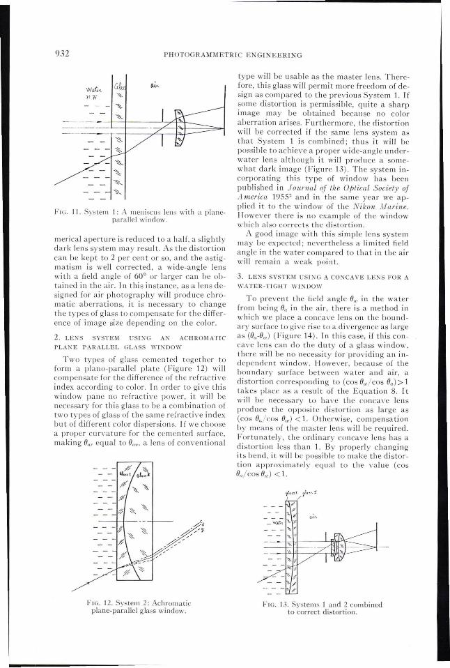
type will be usable as the master lens. Therefore, this glass will permit more freedom of design as compared to the previous System 1. Ifsome distortion is permissible, quite a sharpimage may be obtained because no coloraberration arises. Furthermore, the distortionwill be corrected if the same lens system asthat System 1 is combined; thus it will bepossible to achie\'e a proper wide-angle underwater lens although it will produce a somewhat dark image (Figure 13). The system incorporating this type of window has beenpublished in Journal of th.e Optical Society ofAmerica 19552 and in the same year we applied it to the window of the Nikon Jrarine.However there is no example of the windowwhich also corrects the distortion.
A good image with this simple lens systemmay be expected; nevertheless a limited fieldangle in the water compared to that in the airwill remain a weak point.
;Y
- - .... '-_w~ '\. %___ "A'
"
FlG. 13. Systems 1 and 2 combinedto correct distortion.
3. LE:-iS SYSTDI USI:-iG A CO:-iCA VE LEKS FOR A
\YATER-TIGHT WINDOW
To prevent the field angle Ow in the waterfrom being 0,. in the air, there is a method inwhich we place a concave lens on the boundary surface to give rise to a divergence as largeas (On-Ow) (Figure 14). In this case, if this conca\·e lens can do the duty of a glass window.there will be no necessity for providing an independent window. However, because of theboundary surface between water and air, adistortion correspondi ng to (cos OTu/COS On) > 1takes place as a result of the Equation 8. Itwill be necessary to have the concave lensproduce the opposite distortion as large as(cos O,jcos Ow) < 1. Otherwise, compensationby means of the master lens will be required.Fortunately, the ordinary conca\'e lens has adistortion less than 1. By properly changingits bend, it will be possible to make the distortion approximately equal to the value (cosO,.!cos Ow) < 1.
------1--+-----'--,7"-14___
FIG. 12. System 2: Achromaticplane-parallel glass window.
Wativ..YlW
- - - A
"
FIG. II. System I: A meniscus lens with a planeparallel window.
merical aperture is reduced to a half. a slightlydark lens system may result. As the distortioncan be kept to 2 per cen t or so, and the astigmatism is well corrected, a wide-angle lenswi th a field angle of 60° or larger can be obtained in the air. In this instance, as a lens designed for air photography will produce chromatic aberrations, it is necessary to changethe types of glass to compensate for the difference of image size depending on the color.
2. LE\'S SYSTE\{ USING A1\ ACHROMATIC
PLANE PARALLEL GLASS \\'I='DOW
Two types of glass cemen ted together toform a plano-parallel plate (Figure 12) willcompensate for the difference of the refractiveindex according to color. In order to give thiswindow pane no rcfracti\·e po\\·er, it will benecessary for this glass to be a combination oftwo types of glass of the same refractive indexbut of diff rent color dispersions. If we choosea prop r cun·ature for the cemented surface,making Onr equal to On", a lens of cOI1\·entional

ON DESIGNING UNDERWATER CAMERA LENSES 933
FIG. l-l. System 3: Concave Jens as awater-tight window.
Furthermore, because the chromatic aberrations caused by the boundary surface between water and air have an opposite sign tothose caused by a concave lens, such aberrations can be compensated to some extent bychoosing appropriate types of glass. Thus, ifboth the distortion and the chromatic aberrations are compensated, the conventional lensdesigned for air photography can be used as amaster lens, with the possibility of achieving alens system of large aperture and angularfield. However, owing to the characteristic ofa concave lens which bends the image surfacein the plus direction, choice of a master lenswhich bends the image surface in the oppositeor minus direction is recommended. TheU. W. (Underwater) lens Nikkor 28 mm.1/3.5has been designed on the basis of this conception.
A perfect underwater lens is one in whichother aberrations are additionally correctedby ray tracing to the same degree as those ofthe lens for air photography (Figure 15, Table
FIG. 15. An example of an ideal lensfor photography in air.
t). However, taking into account the concavelens used as the window glass, a slight difference cannot be avoided in the picture angle Oaof the master lens from the underwater picture angle Ow. Consequently, if this lens is usedin the air, some aberrations will unavoidablyremain, giving poor results. Therefore it cannot be used as a perfect lens for air photograp y even though the concave lens is removed.
4. LENS SYSTEM IN COMBINATION WITH A
TELESCOPE SYSTEM
The boundary surface between water andair causes a narrowing of the field angle Ow inthe water in comparison to Oa in the air as expressed in the proportion below:
1 cos Oatan Ow = _._- tan Oa.
1L w cos Ow
Consequently, it will be obvious that by attaching a telescope system with a magnifyingpm er of (l/nw)'(cos Ow/cos 0,,), the pictureangle in the water will be maintained. Thismeans that when the telescope system has a
TABLE 1
NikkoI' 28 mm. f /3.5VII" Nikkor
2811/.1/1.·1/3.5
A berrations on the 111. water
circle 43 rn,1/1. In air Plane A chromatic planeIn water
in diameterglass window glass window
6yo +0.013 +0.224 +0.160 -0.010
6yc -0.001 -0.053 -0.041 -0.010
Distortion -0.5 +11.3 +11.3 +0.3
Picture angle (20) 74° 53.6° 53.6° 59°

934 PHOTOGRAMMETRIC ENGINEERING
use any special camera. Based on this idea wehave designed a glass window for a telephotosystem to be used on a 16 mm. cine camera(Figure 17).
This system, if used as a narrow-angle andlong-focus lens, may produce almost the sameresults as with plane glass window. But whenit is used for a wide-angle, short-focus lens, remarkable improvements will be attained inthe image characteristics (See Table 2). However we can achie\'e a better high performance' lens system by correcting the aberrationsconsidering the master lens (Figure 18, Table3). By comparing the aberration curves, itwill be clear that such a lens system producessuperior results to the conventional one.
5. LENS SYSTEM USIKG CONCENTRIC SPHERI
CAL SURFACES
The refraction, dispersion and distortionthrough the boundary surface between waterand air, are caused by the fact that this surface is flat. If this boundary surface is givensuch a curvature that all the incident rayscome vertically against the surface, the problems will be solved at a single stroke. Wherethe center of the master lens is brought to thecenter of the curvature of this sphericalboundary surface, neither change of pictureangle nor distortion will take place.
\;Vhen a super wide-angle lens is used in thisway, we can expect an excellent lens for useexclusi\'ely under water.
However, the spherical window surface produces a spherical virtual image with its concave side facing the master lens. This masterlens produces an image with a plus curvatur an image plane being convex towardthe lens. The shorter the radius of curvatureof the spherical window surface, the strongerthe curvature of the convex image plane.Therefore, it is desirable to choose a windowwith a radius of curvature as long as permissible. Or it is also desirable to choose as themaster lens a lens producing the image curvature in the opposite direction. Actually, asatisfactory result has been obtained with the
FIG. 18. A more nearly corrected version of thelens shown in Figure 17.
- - - - L........L._-'-....
- - -=---';-=-!---zil"--ft,-1--
FIG. J6. System 4: the Nikkor 25 mm. 1/2,8 designed for unden"ater use exclusively.
power of (l/nw ) and a distortion corr~spond
ing to (cos Ow/cos Of.), both the dIstortIOn andthe picture angle will be compensated. ~or
this purpose, the use of a reversed CalIleotype telescope system is suited, w.ith th~ frontconca\'e lens used as the water-tIght wllldowglass. Fortunately, as the reversed Calileotype telescope system has a min~ls ?istortion,(cos Oa/COS Ow) is likely to be elIminated. Asthe Calileo system uses two groups of lensesas constituents, it is easier to correct chromatic and other aberrations. In addition, it isan ad\'antage that thef-number of the masterlens undergoes no change, so that a bright lel~s
system can be obtained. Such a lens system IS
recommended by Dr. J\'anoA, and some practical examples are given 3.4 On this basis, wehave made a trial lens, Nikkor 25 mm. f/2.8.designed exclusi\'ely for underwater use(Figure 16). Howe\'er, as a result of the correction performed by ray tracing throug!l th.eentire system of the lens, the magnIficatIOn IS
slightly different from (l/nw ), and could notform a perfect telescope type. In any case,when a telescope system is used, it is advantageous that the image position be maintained.Consequently if the aberrations are correctedonly by the u'se of a telescope sys~e!ll, it willbe possible to apply the camera ongl nally designed for air use without alteration to underwater use. In other words, there is no need to
FIG. 17. A glass \Vindo\" designed for a telephotosystem for use on a J6-mm. movie camera.

A bel'rations on th.ecircle J3 11/111.
in diameter
Distortion
Picture angle (211)
Focal length
ON DESIGNING l'NDER\\XI'ER C.\~IERA LENSES
TABLE 2. CO~IPARISOJ' OF CHAI{ACTERISTfCSNikkor for 16 111111. cine 13 I11111.f/I.8
[11 ~vater
[n air p lane glassplate
+0.00-1, +0 .051
+0.001 -0.011
-1.28 +3.95
53° 39°
13111111. 13111111.
Nikkor for 16 n1lll. cine 50 III 111. f/I .8
Telescope system(fj=I/I.2)
-0.008
+0.002
+0.71
10.83111111.
935
Distortion
Picture angle (211)
Focal length
-0.003
+0.002
-037
50l111ll.
+0.035
-0.008
o
50 III Ill.
-0.007
-0.002
-0.19
41.64 III Ill.
TABLE 3. UKDERWATER LENS FOR16 111111. CIKE CAMERAf= 10 111111. (0.4 inch)
B-j=25.4 111111. (l inch)
tion nor dispersion will arise on the front surface of the window. It is therefore possible topermit the front surface of the window toha\'e any desirable cUr\'ature or a Rat surface.
COl\CLUSrON
Because large aberrations occur throughthe boundary surface between water and air,it is not desirable to use an ordinary lens forunderwater photography wi thou t al teration,unless the field angle of the lens does not exceed about 20°, or some special contri\'ance isintroduced at the window surface in contact
Nikkor 21 111m. f/4 (Frontispiece and Figure19) by ray tracing. COllsidering the externalpressure, it is preferahle to use a spherical surface window rather than a Rat one. (Exceptsome difficulties are invoked in fabrication.)Thus, with this spherical window surface asuper wide-angle lens, or fish-eye len, etc.may be used as an underwater lens, the fieldangle remaining the same.
In the United States, trial lens systemssuch as this have been made fi ,6.7. I n practice,however, it is necessary to bring the positionof the entrance pupil in coincidence with thecenter of the spherical surface of the windoll'.I f this position is displaced, or a lens is used inwhich the location of the entrance pupil \'arieswith the incidence angle of the ray, the perpendicularity of the incident rays with respectto the spherical window may undergo achange. There then arises the possibility ofcausing aberrations, except where these aberrations are corrected 8 Of course, we must admit a decrease, even slightly, of thef-numberas compared to that which can be gi\'en for airphotography. On the other hand, if the typeof glass used for the windo\\' is of the same refractive index and dispersion as those ofwater, it is not always necessary to givespherical concentric cUr\'atures to the surfaces of the window. Because neither refrac-
A berra/ions 011 /lieClrrle 13 III/II.
m dialileter
D.y"
Distortion
Field angle (20)
+0.005
+0.002
-1.5

936
- ".5
PHOTOGRAMMETRIC ENGINEERING
--+-1- B • 30·
9. 4-2.5·
(}. 30·
"2.0 _j.
FIG. 19. Aberration curves of the Nikkor 21 111111. f /4 used through a spherical glass window forunderwater photography. Angular field, 85°; focal length, 17.64 111111.; 111aximum aperture, f /4.
with the water. From the designing point of"iew, better results can be obtained if a lenssystem is designed, including the window,than if an ordinary lens is used.
To achieve a good lens for underwaterphotography, it is recommended that it be designed from the beginning. It is not advantageous to attempt to design a lens usable bothin water and in the air. Also note that lensesexclusively designed for underwater use donot always have a Rat surface in contact withwater; therefore, if we take pictures in the airusing these lenses, the position of the imageplane will undergo a change, resulting in anou t-of-focus image.
We have not only studied several possibletypes of underwater lenses, but have madetrial lenses for comparison with pictures takenwith conventional lenses. We find that ourunderwater lenses can obviously bring aboutthe same good performance as that obtainedby the lenses used in the air in their calculatedaberrations as well as in the actual photographs taken.
Among our trial lenses, the 28 mm. f/3.5has been produced in large quantities since1965. It is supplied as an interchangeable lensfor the all-weather camera Nikonos. This lens,though slightly inferior the 35 mm. f/2.5 inbrigh tness, is superior in picture angle, in correction of distortion, correction of color aberrations, and in other optical performances. Tt
results in an excellent resolving power up tothe circumference of the image field.
It becomes evident that if we conduct afaithful optical design by ray tracing, such asused in atmospheric lenses, there is a possibility of improving the performance of underwater lenses to the same degree as that oflenses used for air photography.
'vYe have studied only a few of the manyphotographic lenses available. 10/e hope to beinvolved in the development of more advanced lens systems, corrected for improvedbrightness and wider picture angles. In thepast this field has been neglected. With the increased interest in underwater photography,we can expect definite improvements in underwater lens designs.
REFERENCES
1. A. Ivanoff, Revue d'Optiqu No.4, April, 1953.p. 193-203
2. M. Thorndike, Journal of the Optical Society ofAmerica, Yol. 45, July, 1955. p. 584-585
3. A. Ivanoff, U. S. Patent 10 . 2730014 patentedJan ..1956
4. A. Ivanoff, S.M.P.T.E. Vol. 69, p. 264-2665. ---, Modern Photography, April 1966. p. 64
656. G. 1'. McNeil, Photogram.m.etric Engineering,
January, 1966, p. 37-427. G. T. McNeil, S.P.I.E., Feb./Mar., 1966. p. 95
1028. M. Thorndike, Journal of the Optical Society of
A men:Ca, Vol. 40, Dece111ber, 1950. p. 823-824
See announcement of 1968 Congress in Switzerland on page 940.