on flywheel leg press design and its benefits have developed a gravity independent mechanical ......
TRANSCRIPT
ISSN 1750-9823 (print)
International Journal of Sports Science and Engineering
Vol. 07 (2013) No. 02, pp. 087-100
On Flywheel Leg Press Design and its Benefits
Dodge R., Fisher B., King J., Kuehl P., Matsuki S., Boyajian D., Gegner J., Geisler J., Dailey J.
Physics and Engineering, Taylor University, 236 W Reade Ave, Upland, Indiana 46989-1001
(Received November 14, 2012, accepted December 9, 2012)
Abstract. We have developed a gravity independent mechanical device that provides resistance in both the concentric and eccentric motions of the leg press exercise that is to be used in future human performance studies. This paper will provide an overview of the engineering process used in designing this specialty press machine. We will also qualitatively and quantitatively compare and contrast the force curves for the free-weight leg press as well as our newly designed fly-wheel leg press (FWLP) for the purposes of evaluating the effectiveness of the new device.
Keywords: flywheel, leg press, engineering
1. Introduction One of the purposes of this paper is to present the design process by which we engineered this particular
gravity-independent ergometer (GEm) leg press. We employed a modified design process as defined by Ertas and Jones [3]. This process included recognition of need, conceptualization, development of work breakdown structure, feasibility assessment, preliminary design, funding approval, detailed design, production planning, and production.
Gravity dependent exercise equipment have long provided an effective means of developing muscle mass in its users [4]. Research and development in the area of human performance has also long sought out more effective means of working the musculoskeletal realm of the human body which we envision to be the topic of future studies on this machine. One of the first to work with one such different means, in the medium of fly wheels, was A.V. Hill in the 1920s [10]. However, flywheels originated over 100 years ago to keep machinery running smoothly from cycle to cycle, as in the case automobile engines [2].
Various other research efforts have shown that the inertial loads provided by flywheels, most closely resemble the challenges of human musculoskeletal development in everyday exertions [10]. This in combination with the fact that many athletic and day-to-day leg movements having neuromuscular similarities to those movements exerted during the leg press [6], provided the initiations for the undertaking of this particular project – the GEm leg press.
In exercise, concentric training is based on muscle contraction, which is commonly referred to as being a “positive” motion. Eccentric training is based on muscle extension, and is so referred to as “negative” motion [3]. Clear demonstration of the superiority of resistance training that combines both concentric and eccentric actions over merely concentric ones alone, has been the subject of recent research studies [4]. To this end, inertial flywheels have provided an effective means of implementing equipment that produces resistance in both the eccentric and concentric directions [12][8]. We moved forward with the engineering design process of the GEm leg press based off of a desire to build a piece of exercise equipment that would provide an effective means of exercise for future human performance studies as previously stated. These human performance studies also need a way of measuring the forces being exerted along with the corresponding displacements, for quantifying physical properties, e.g. work and power, in conducting research.
Moving forward with the design of the GEm leg press involved accounting for various factors, some of which have been set forth in past studies. For example, in the commonly used Engineering Anthropometric Methods textbook it is said that even slight, almost imperceptible changes in limb angles can have very different results in exerted forces [13]. Because of this, and our desire to develop a leg press that closely produces a movement common to day-to-day human activities[11], led to the impetus for the design of the current machine. With the knee angle defined as 0º in a fully extended position, the leg press motion ends
Published by World Academic Press, World Academic Union
Dodge R., et al: On Flywheel Leg Press Design and its Benefits 88
with the subject contracting their knees to a knee flexion of approximately 90º-100º [5]. For athletes with healthy knees, performing the squat, or similarly the leg press, at higher knee flexion angles (90º-110º) should not be problematic, as long as heavy loads are not used excessively [7]. Thus, we knew we needed to design our leg press to accommodate knee angles approaching these values for the range of subjects to study. In addition, previous research has shown that various foot placements for the leg press exercise are preferred by different users. It is recommended that users employ a foot angle that is most comfortable for them, and thus a large foot platform is best to accommodate the variety of user preferences [6].
Also taken into design consideration is that, in a rotary system, other factors in addition to inertia are always present, and a constant torque opposing wheel rotation can be detected in a run-down test. This test involves suspending a known mass from the inertial wheel at a given distance from the floor and allowing the mass to fall [10]. Based on such findings, this setup is appropriate for measuring the actual user-exerted forces during exercise as achieved through the use of four polymer flywheels of varying dimensions to achieve a comparable gravity-dependent resistance of 1500 lb [1].
Not included in this machine is a device able to detect the position of the flywheel. The advantage of being able to track the flywheel at discrete time intervals is that it allows torque and velocity to be determined throughout the exertion period. This could be used in parallel with a strain gage system to compare and achieve more accurate data readings [10]. Future work on this machine should include a rotary encoder to collect such measurements.
2. Design The purpose of this particular project was to design and manufacture a machine that utilizes a
mechanism to store and release energy from a leg press motion in order to study human performance by measuring certain parameters during this motion. From our research, it was determined that the most effective way of doing this was through the fly wheel mechanism. The following is a concise list of design drivers:
To maintain leg press biomechanics To minimize non-flywheel inertial masses The drivetrain utilizing a belt that is wound/unwound on rotating shaft To be able to sense both force and displacement measurements To accommodate users ranging in height from five to six feet eight inches tall To maintain overall structural stability
These design drivers allowed the engineering process to be focused yet allow for restricted freedom within the various subsystems. The following elaborates upon each of these specialized areas.
Leg press biomechanics are, simply put, the body’s motion in a typical leg press movement. As our research indicated, the leg press is an exceptional exercise for simulating day-to-day leg movements and exertions. Thus, we wanted to maintain the integrity of the leg press exercise in our machine design. To do this, we had to fully understand what the leg press entailed.
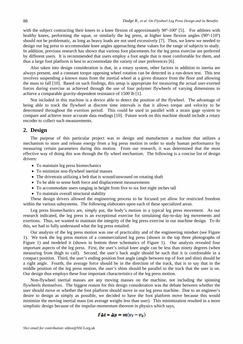
Our analysis of the leg press motion was one of practicality and of the engineering mindset (see Figure 1). We took the leg press motion of a commercialized leg press (shown in the top three photographs of Figure 1) and modeled it (shown in bottom three schematics of Figure 1). Our analysis revealed four important aspects of the leg press. First, the user’s initial knee angle can be less than ninety degrees (when measuring from thigh to calf). Second, the user’s back angle should be such that it is comfortable in a compact position. Third, the user’s ending position foot angle (angle between top of foot and shin) should be a right angle. Fourth, the average force should be in the direction of the track, that is to say that in the middle position of the leg press motion, the user’s shins should be parallel to the track that the user is on. Our design thus employs these four important characteristics of the leg press motion.
Non-flywheel inertial masses are any moving masses on the machine, not including the spinning flywheels themselves. The biggest reason for this design consideration was the debate between whether the user should move or whether the foot platform should move in our leg press machine. Due to an engineer’s desire to design as simply as possible, we decided to have the foot platform move because this would minimize the moving inertial mass (on average weighs less than user). This minimization resulted in a more simplistic design because of the impulse-momentum theorem in physics which says,
SSci email for contribution: [email protected]
International Journal of Sports Science and Engineering, 7(2013) 2, pp 087-100 89
Fig. 1: Leg Press Biomechanical Analysis
Thus, a larger moving mass results in a larger force further resulting in a larger force requirement placed on the materials used in the frame, drivetrain belt, etc.
Our desire to design the machine around the belt, drivetrain connection came simply from the fact that this subsystem is the crux of this particular leg press design. We did not want to compromise the design in this area but rather wanted to design it first and have all other systems be designed to accommodate it. Also, because we wanted the ability to record and analyze data from the users of this machine, we wanted the ability to measure the force and displacement of the foot platform. For this reason, we added both a strain gage and a string potentiometer at this location. Based on these sensor readings, we are able to obtain force and displacement readings and to compute parameters such as power, work, and speed.
2.1. Mechanics Due to the time constraints of an academic year, we decided to use primarily 8020 engineered
aluminum for the material building of the frame structure. This not only saved time but also aided the senior capstone team in their design and build phase. The following sections outline the reasoning and considerations of the mechanical design.
2.1.1 Structure Our intent in designing the structure of the leg press machine was basic. We wanted it to be able to
withstand user forces, with minimal member deflections, as well as to minimize the cost. Again, in the structure, mostly 8020 material was utilized. The structure of the GEm leg press machine consists of both the frame of the machine itself as well as the seating system. Each of these systems were designed separately with key integration points in mind.
2.1.2 Frame The finalized design driver of the GEm leg press frame was simplicity. To minimize the complexity of
the exercise movement, we decided on a two rail, flat track design. This allowed for both structural integrity as well as simplicity of force analysis, as opposed to an angled track. To stick with this linear flat track we accounted for both machine rocking, due to the back and forth forces of the user, as well as side-to-side wobble.
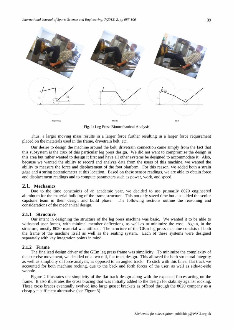
Figure 2 illustrates the simplicity of the flat track design along with the expected forces acting on the frame. It also illustrates the cross bracing that was initially added to the design for stability against rocking. These cross braces eventually evolved into large gusset brackets as offered through the 8020 company as a cheap yet sufficient alternative (see Figure 3).
SSci email for subscription: [email protected]
Dodge R., et al: On Flywheel Leg Press Design and its Benefits 90
Fig. 2: Flat track design and expected forces
Due to customer constraints the frame had to stay within an 8’x3’ footprint. Members were then analyzed based on these design constraints. Analysis was performed with maximum capacity in mind. Maximum capacity in this case refers to the heaviest expected user exerting the strongest possible force on the foot platform. With these forces in mind, a simply supported, centrally loaded beam deflection analysis was performed using the equation:
The following table shows the results and a comparison of a single beam design against our chosen two beam design.
Table 1: Frame deflection analysis
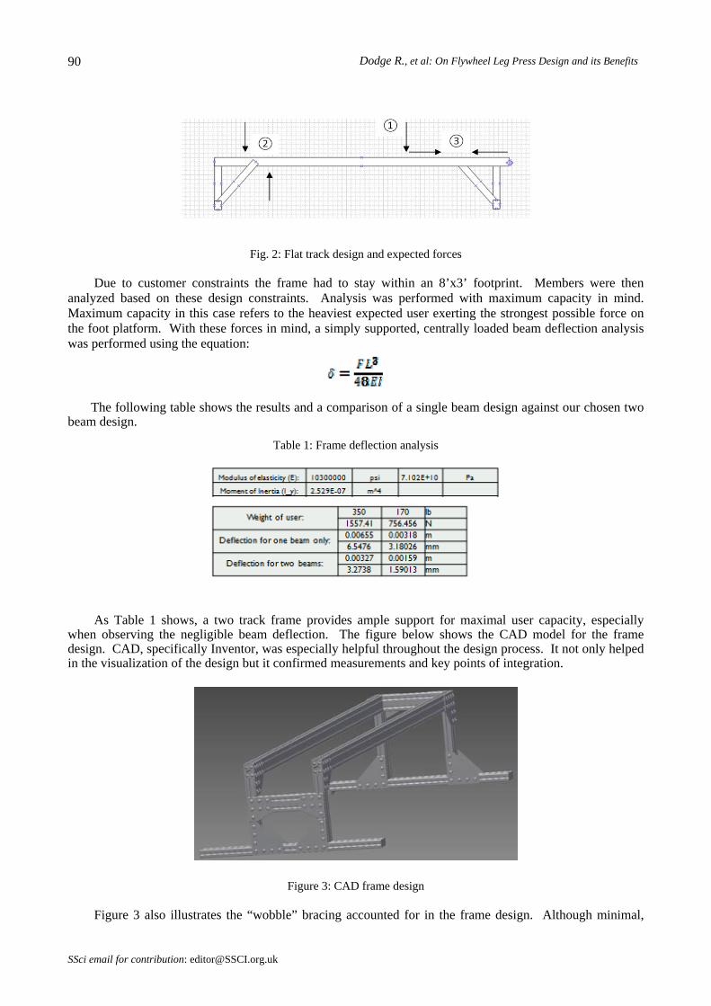
As Table 1 shows, a two track frame provides ample support for maximal user capacity, especially when observing the negligible beam deflection. The figure below shows the CAD model for the frame design. CAD, specifically Inventor, was especially helpful throughout the design process. It not only helped in the visualization of the design but it confirmed measurements and key points of integration.
Figure 3: CAD frame design
Figure 3 also illustrates the “wobble” bracing accounted for in the frame design. Although minimal,
SSci email for contribution: [email protected]
International Journal of Sports Science and Engineering, 7(2013) 2, pp 087-100 91 wobble from left to right was designed for in the frame with the bracings from vertical members to horizontal floor members. A further design consideration consisted of machine “walking” while in use. This was rationalized in the design by simply realizing the application of Newton’s 3rd Law where for every action there is an equal and opposite reaction (collinear). In other words, without any external forces the machine will stay stationary throughout use.
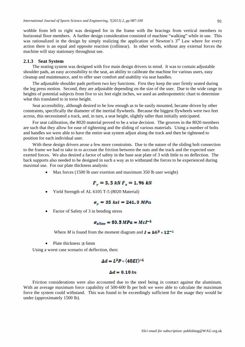
2.1.3 Seat System The seating system was designed with five main design drivers in mind. It was to contain adjustable
shoulder pads, an easy accessibility to the seat, an ability to calibrate the machine for various users, easy cleanup and maintenance, and to offer user comfort and usability via seat handles.
The adjustable shoulder pads perform two key functions. First they keep the user firmly seated during the leg press motion. Second, they are adjustable depending on the size of the user. Due to the wide range in heights of potential subjects from five to six feet eight inches, we used an anthropometric chart to determine what this translated to in torso height.
Seat accessibility, although desired to be low enough as to be easily mounted, became driven by other constraints, specifically the diameter of the inertial flywheels. Because the biggest flywheels were two feet across, this necessitated a track, and, in turn, a seat height, slightly taller than initially anticipated.
For seat calibration, the 8020 material proved to be a wise decision. The grooves in the 8020 members are such that they allow for ease of tightening and the sliding of various materials. Using a number of bolts and handles we were able to have the entire seat system adjust along the track and then be tightened to position for each individual user.
With these design drivers arose a few more constraints. Due to the nature of the sliding bolt connection to the frame we had to take in to account the friction between the nuts and the track and the expected user exerted forces. We also desired a factor of safety in the base seat plate of 3 with little to no deflection. The back supports also needed to be designed in such a way as to withstand the forces to be experienced during maximal use. For our plate thickness analysis:
Max forces (1500 lb user exertion and maximum 350 lb user weight)
Yield Strength of AL 6105 T-5 (8020 Material)
Factor of Safety of 3 in bending stress
Where M is found from the moment diagram and
Plate thickness 6mm
Using a worst case scenario of deflection, then:
Friction considerations were also accounted due to the steel being in contact against the aluminum. With an average maximum force capability of 500-600 lb per bolt we were able to calculate the maximum force the system could withstand. This was found to be exceedingly sufficient for the usage they would be under (approximately 1500 lb).
SSci email for subscription: [email protected]
Dodge R., et al: On Flywheel Leg Press Design and its Benefits 92
Figure 4: Seating system (handles not shown)
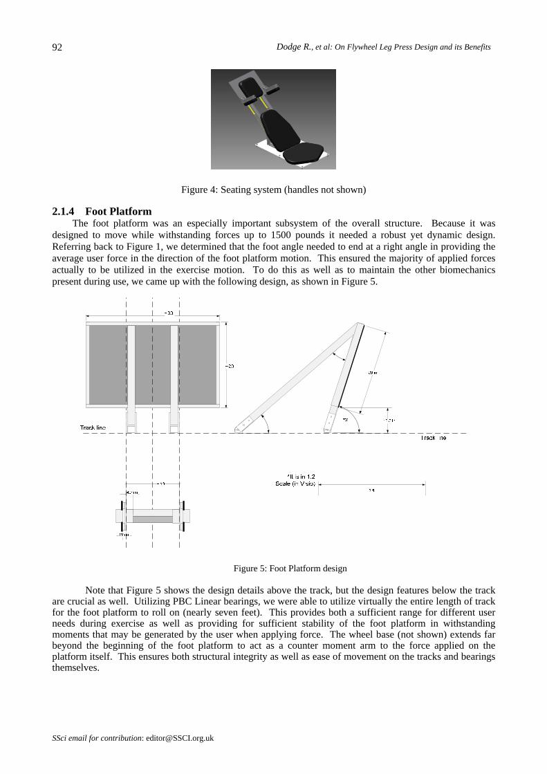
2.1.4 Foot Platform The foot platform was an especially important subsystem of the overall structure. Because it was
designed to move while withstanding forces up to 1500 pounds it needed a robust yet dynamic design. Referring back to Figure 1, we determined that the foot angle needed to end at a right angle in providing the average user force in the direction of the foot platform motion. This ensured the majority of applied forces actually to be utilized in the exercise motion. To do this as well as to maintain the other biomechanics present during use, we came up with the following design, as shown in Figure 5.
Figure 5: Foot Platform design
Note that Figure 5 shows the design details above the track, but the design features below the track are crucial as well. Utilizing PBC Linear bearings, we were able to utilize virtually the entire length of track for the foot platform to roll on (nearly seven feet). This provides both a sufficient range for different user needs during exercise as well as providing for sufficient stability of the foot platform in withstanding moments that may be generated by the user when applying force. The wheel base (not shown) extends far beyond the beginning of the foot platform to act as a counter moment arm to the force applied on the platform itself. This ensures both structural integrity as well as ease of movement on the tracks and bearings themselves.
SSci email for contribution: [email protected]
International Journal of Sports Science and Engineering, 7(2013) 2, pp 087-100 93
Figure 6: Bearing to track connection
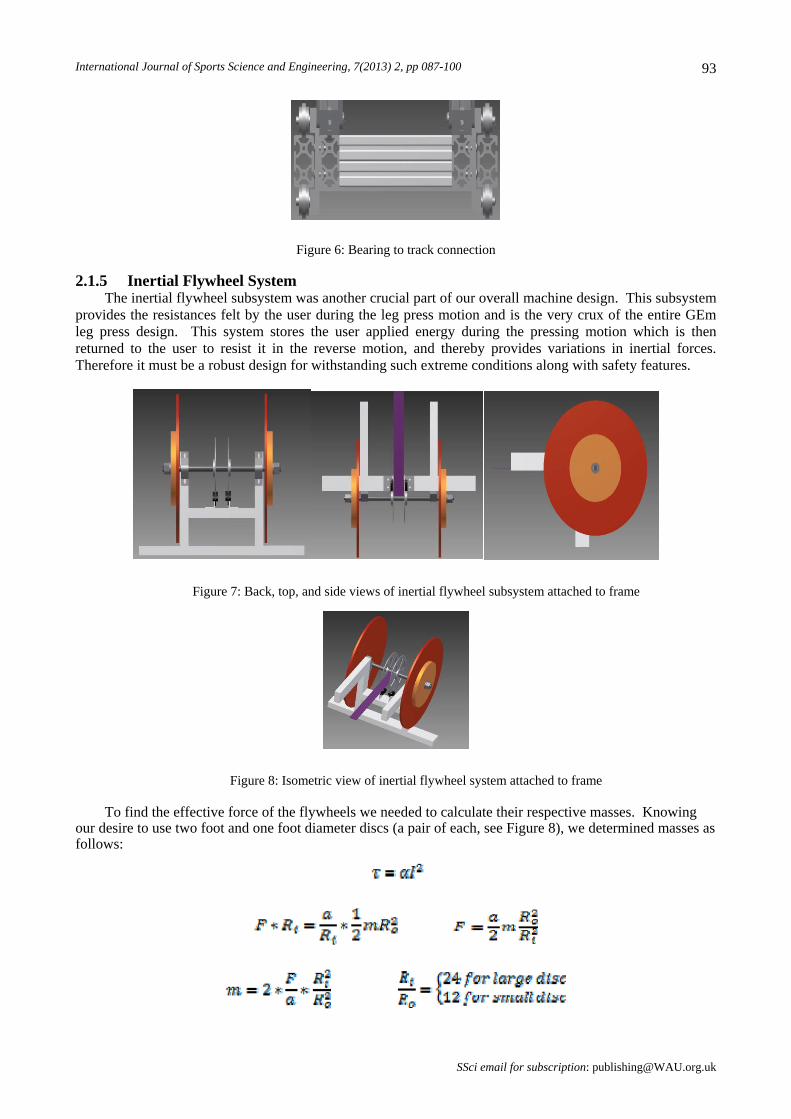
2.1.5 Inertial Flywheel System The inertial flywheel subsystem was another crucial part of our overall machine design. This subsystem
provides the resistances felt by the user during the leg press motion and is the very crux of the entire GEm leg press design. This system stores the user applied energy during the pressing motion which is then returned to the user to resist it in the reverse motion, and thereby provides variations in inertial forces. Therefore it must be a robust design for withstanding such extreme conditions along with safety features.
Figure 7: Back, top, and side views of inertial flywheel subsystem attached to frame
Figure 8: Isometric view of inertial flywheel system attached to frame
To find the effective force of the flywheels we needed to calculate their respective masses. Knowing our desire to use two foot and one foot diameter discs (a pair of each, see Figure 8), we determined masses as follows:
SSci email for subscription: [email protected]

Dodge R., et al: On Flywheel Leg Press Design and its Benefits 94
Based on these calculations and a desired effective force felt by the user at typical leg press accelerations (approximated as a squat to standing acceleration), the thickness of the discs were determined for a particular PVC polymer material chosen (see Table 3).
Table 2: Table of approximate user accelerations (m/s^2), effective force felt (N), and coinciding masses (kg)
Acceleration
lb N 1 2 3 4 5 6 7 8 9 1
100 445 2.225 1.113 0.742 0.556 0.445 0.371 0.318 0.278 0.247 0.2225
200 890 4.45 2.225 1.483 1.113 0.89 0.742 0.636 0.556 0.494 0.445
300 1335 6.675 3.338 2.225 1.669 1.335 1.113 0.954 0.834 0.742 0.6675
400 1780 8.9 4.45 2.967 2.225 1.78 1.483 1.271 1.113 0.989 0.89
500 2225 11.13 5.563 3.708 2.781 2.225 1.854 1.589 1.391 1.236 1.1125
600 2670 13.35 6.675 4.45 3.338 2.67 2.225 1.907 1.669 1.483 1.335
700 3115 15.58 7.788 5.192 3.894 3.115 2.596 2.225 1.947 1.731 1.5575
800 3560 17.8 8.9 5.933 4.45 3.56 2.967 2.543 2.225 1.978 1.78
900 4005 20.03 10.01 6.675 5.006 4.005 3.338 2.861 2.503 2.225 2.0025
1000 4450 22.25 11.13 7.417 5.563 4.45 3.708 3.179 2.781 2.472 2.225
1100 4895 24.48 12.24 8.158 6.119 4.895 4.079 3.496 3.059 2.719 2.4475
1200 5340 26.7 13.35 8.9 6.675 5.34 4.45 3.814 3.338 2.967 2.67
1300 5785 28.93 14.46 9.642 7.231 5.785 4.821 4.132 3.616 3.214 2.8925
1400 6230 31.15 15.58 10.38 7.788 6.23 5.192 4.45 3.894 3.461 3.115
1500 6675 33.38 16.69 11.13 8.344 6.675 5.563 4.768 4.172 3.708 3.3375
Eff.
Force
0
Table 3: PVC material chosen based off of its tensile strength and economic feasibility
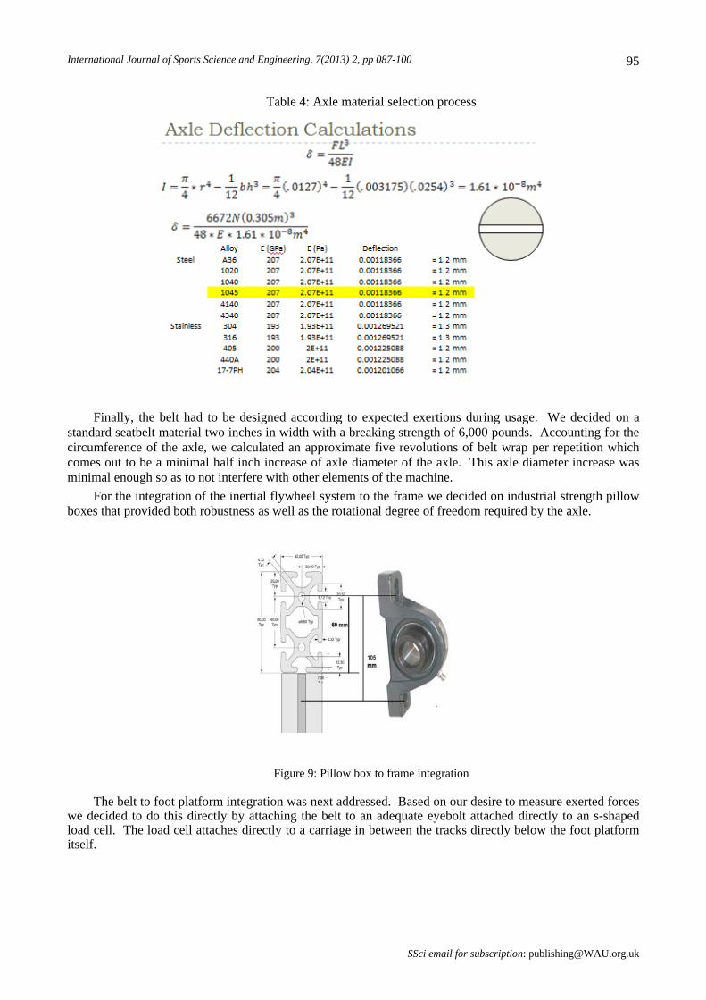
The axle was then designed for the system with a minimization of deflection, flywheel fit, and belt attachment in mind. For the minimization of axle deflection, steel 1045 was chosen as both an economic and sufficient option with a maximum deflection calculation yielding only 1.2 mm.
SSci email for contribution: [email protected]
International Journal of Sports Science and Engineering, 7(2013) 2, pp 087-100 95
Table 4: Axle material selection process
Finally, the belt had to be designed according to expected exertions during usage. We decided on a standard seatbelt material two inches in width with a breaking strength of 6,000 pounds. Accounting for the circumference of the axle, we calculated an approximate five revolutions of belt wrap per repetition which comes out to be a minimal half inch increase of axle diameter of the axle. This axle diameter increase was minimal enough so as to not interfere with other elements of the machine.
For the integration of the inertial flywheel system to the frame we decided on industrial strength pillow boxes that provided both robustness as well as the rotational degree of freedom required by the axle.
Figure 9: Pillow box to frame integration
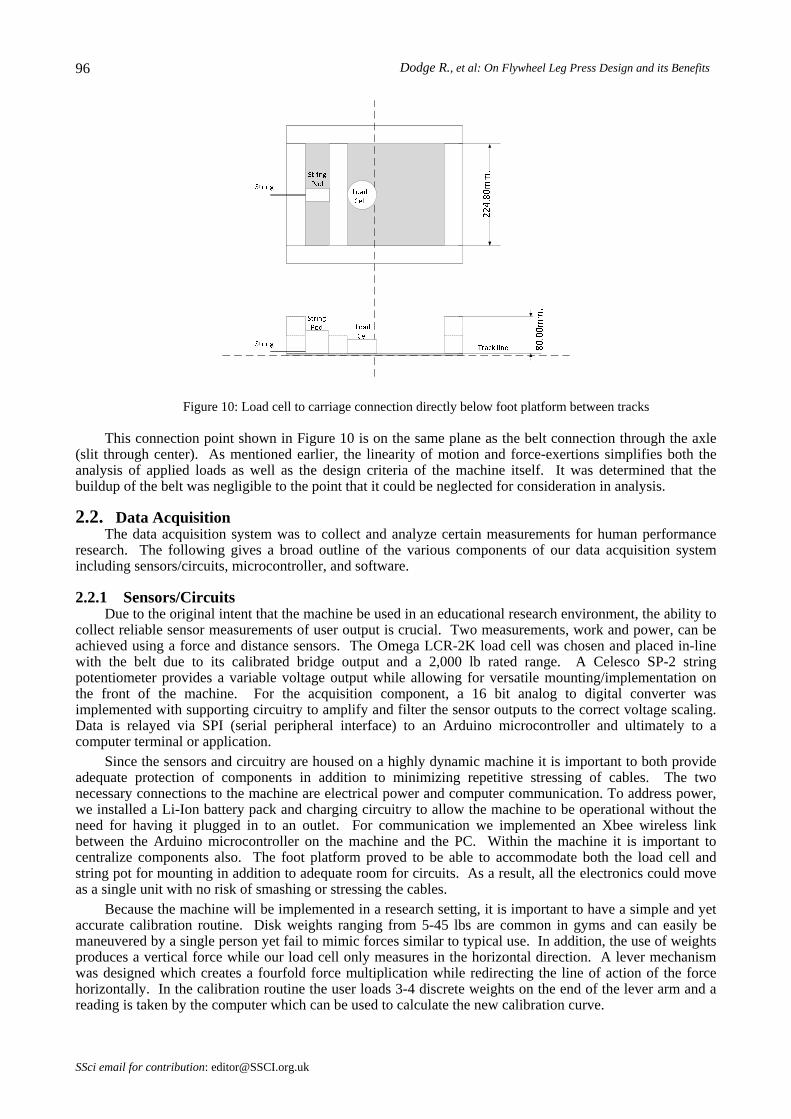
The belt to foot platform integration was next addressed. Based on our desire to measure exerted forces we decided to do this directly by attaching the belt to an adequate eyebolt attached directly to an s-shaped load cell. The load cell attaches directly to a carriage in between the tracks directly below the foot platform itself.
SSci email for subscription: [email protected]
Dodge R., et al: On Flywheel Leg Press Design and its Benefits 96
Figure 10: Load cell to carriage connection directly below foot platform between tracks
This connection point shown in Figure 10 is on the same plane as the belt connection through the axle (slit through center). As mentioned earlier, the linearity of motion and force-exertions simplifies both the analysis of applied loads as well as the design criteria of the machine itself. It was determined that the buildup of the belt was negligible to the point that it could be neglected for consideration in analysis.
2.2. Data Acquisition The data acquisition system was to collect and analyze certain measurements for human performance
research. The following gives a broad outline of the various components of our data acquisition system including sensors/circuits, microcontroller, and software.
2.2.1 Sensors/Circuits Due to the original intent that the machine be used in an educational research environment, the ability to
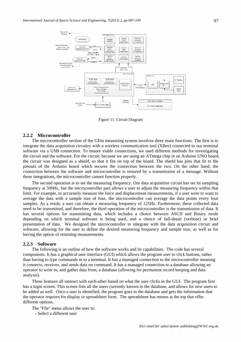
collect reliable sensor measurements of user output is crucial. Two measurements, work and power, can be achieved using a force and distance sensors. The Omega LCR-2K load cell was chosen and placed in-line with the belt due to its calibrated bridge output and a 2,000 lb rated range. A Celesco SP-2 string potentiometer provides a variable voltage output while allowing for versatile mounting/implementation on the front of the machine. For the acquisition component, a 16 bit analog to digital converter was implemented with supporting circuitry to amplify and filter the sensor outputs to the correct voltage scaling. Data is relayed via SPI (serial peripheral interface) to an Arduino microcontroller and ultimately to a computer terminal or application.
Since the sensors and circuitry are housed on a highly dynamic machine it is important to both provide adequate protection of components in addition to minimizing repetitive stressing of cables. The two necessary connections to the machine are electrical power and computer communication. To address power, we installed a Li-Ion battery pack and charging circuitry to allow the machine to be operational without the need for having it plugged in to an outlet. For communication we implemented an Xbee wireless link between the Arduino microcontroller on the machine and the PC. Within the machine it is important to centralize components also. The foot platform proved to be able to accommodate both the load cell and string pot for mounting in addition to adequate room for circuits. As a result, all the electronics could move as a single unit with no risk of smashing or stressing the cables.
Because the machine will be implemented in a research setting, it is important to have a simple and yet accurate calibration routine. Disk weights ranging from 5-45 lbs are common in gyms and can easily be maneuvered by a single person yet fail to mimic forces similar to typical use. In addition, the use of weights produces a vertical force while our load cell only measures in the horizontal direction. A lever mechanism was designed which creates a fourfold force multiplication while redirecting the line of action of the force horizontally. In the calibration routine the user loads 3-4 discrete weights on the end of the lever arm and a reading is taken by the computer which can be used to calculate the new calibration curve.
SSci email for contribution: [email protected]
International Journal of Sports Science and Engineering, 7(2013) 2, pp 087-100 97
Figure 11: Circuit Diagram
2.2.2 Microcontroller The microcontroller section of the GEm measuring system involves three main functions. The first is to
integrate the data acquisition circuitry with a wireless communication tool (XBee) connected to our terminal software via a USB connection. To ensure viable connections, we used different methods for investigating the circuit and the software. For the circuit, because we are using an ATmega chip in an Arduino UNO board, the circuit was designed as a shield, so that it fits on top of the board. The shield has pins that fit to the pinouts of the Ardunio board which secures the connection between the two. On the other hand, the connection between the software and microcontroller is ensured by a transmission of a message. Without these integrations, the microcontroller cannot function properly.
The second operation is to set the measuring frequency. Our data acquisition circuit has set its sampling frequency at 500Hz, but the microcontroller part allows a user to adjust the measuring frequency within that limit. For example, to accurately measure the force and displacement measurements, if a user were to want to average the data with a sample size of four, the microcontroller can average the data points every four samples. As a result, a user can obtain a measuring frequency of 125Hz. Furthermore, these collected data need to be transmitted, and therefore, the third operation of the microcontroller is the transmission of data. It has several options for transmitting data, which includes a choice between ASCII and Binary mode depending on which terminal software is being used, and a choice of full-detail (verbose) or brief presentation of data. We designed the microcontroller to integrate with the data acquisition circuit and software, allowing for the user to define the desired measuring frequency and sample size, as well as for having the option of returning measurements.
2.2.3 Software The following is an outline of how the software works and its capabilities. The code has several
components. It has a graphical user interface (GUI) which allows the program user to click buttons, rather than having to type commands in to a terminal. It has a managed connection to the microcontroller meaning it connects, receives, and sends data on command. It has a managed connection to a database allowing an operator to write to, and gather data from, a database (allowing for permanent record keeping and data analysis).
These features all interact with each-other based on what the user clicks in the GUI. The program first has a login screen. This screen lists all the users currently known to the database, and allows for new users to be added as well. Once a user is identified, the program goes to the database and gets the information that the operator requires for display in spreadsheet form. The spreadsheet has menus at the top that offer different options.
The "File" menu allows the user to: - Select a different user
SSci email for subscription: [email protected]

Dodge R., et al: On Flywheel Leg Press Design and its Benefits 98
-Save as ".csv" so that the operator can do more analysis of the data in a spreadsheet program -Quit The "Run" menu allows the user to: -Start (tell the microcontroller to start sending sensor readings, and store the readings in the database, as a new set for the selected user) -Stop (tell the microcontroller to stop sending sensor readings) -Calibrate (this guides the user through the process of calibrating the sensors by asking for different weights and storing this information. It then compares the sensor value with the (known) expected value, and determines an offset equation to calibrate the readings.
3. Comparative Study Pictured below are the force versus time curves for both a standard, gravity-dependent leg press machine
as well as our GEm leg press machine.
Figure 12: Force chart comparison (left figure [9])
Taking a look at a repetition comparison, for the figure on the right start at ~46 seconds and end at ~48 seconds, we can get a good notion of the effective differences between the two machines. By normalizing the curves (i.e. taking the maximum value to simply be one), one can see the consistency and maximum forces that are applied during the GEm leg press exercise as opposed to the traditional leg press exercise. In the GEm leg press, the maximum force is felt by the user at both the beginning (46 sec) and end (48 sec) of the repetition (note: a jump in the force can be seen in the middle of the repetition as caused by the impulse of the sled “turn-around”). Comparing this to the traditional leg press exercise where the maximum force is seen at around 75% of the repetition, one can clearly see that the GEm leg press gives a higher average force as well as forces at key positions of the leg press exercise (the beginning and the end). A more in depth study of user effectiveness of the GEm leg press will be conducted with test subjects to further substantiate this preliminary observation.
4. Conclusion The GEm leg press has been shown to be an effective alternative to exercising the leg press muscles of
the human body. The design process used proved to be an effective means for attaining a viable machine for studying muscular development achieved by a gravity independent machine versus the more conventional weight stack machines. Future studies and improvements can be done in the area of material optimization, sensor additions, and software improvements.
5. Acknowledgements We would like to thank Ted Mitchell, Jon Moore, and Will Mitchell for their help in design of the software and safety system respectively. We would also like to thank Dr. Joel Gegner, Dr. Jonathan Geisler, Dr. David Boyajian, and Professor Jeff Dailey for their input into the design process. Also, a special thanks
SSci email for contribution: [email protected]
International Journal of Sports Science and Engineering, 7(2013) 2, pp 087-100 99 to Dr. Erik Hayes for funding the project as the customer.
6. References [1] Berg, Hans E.; Tesch, Per A., “A Gravity-Independent Ergometer to be Used for Resistance Training in Space”
Aviation, Space, and Environmental Medicine, 1994
[2] Bitterly, Jack G., “Flywheel Technology: Past, Present, and 21st Century Projections” IEEE AES Systems Magazine, 1998
[3] Coombs, Dana Joseph. “DESIGN OF USER-WEIGHT-BASED EXERCISE MACHINES." Virginia Polytechnic Institute and State University, 7 Feb. 1997. Web. 16 Feb. 2012. <http://scholar.lib.vt.edu/theses/public/etd-5115131974430/DJC_THES.PDF>.
[4] Dudley, Gary A., et al., “Importance of Eccentric Actions in Performance Adaptations to Resistance Training” Aviation, Space, and Environmental Medicine, 1991
[5] Escamilla, Rafael F.; et al., “Biomechanics of the knee during closed kinetic chain and open kinetic chain exercises” Medicine & Science in Sports & Exercise, 1998
[6] Escamilla, R. F., G. S. Fleisig, N. Zheng, J. E. Lander, S. W. Barrentine, J. R. Andrews, B. W. Bergemann, and C. T. Moorman, III. Effects of technique variations on knee biomechanics during the squat and leg press. Med. Sci. Sports Exerc., Vol. 33, No. 9, 2001, pp. 1552-1566.
[7] Escamilla, R. F. Knee biomechanics of the dynamic squat exercise. Med. Sci. Sports Exerc., Vol. 33, No. 1, 2001, pp. 127-141.
[8] Hans E. Berg, Per A. Tesch, Force and power characteristics of a resistive exercise device for use in space, Acta Astronautica, Volume 42, Issues 1–8, January–April 1998, Pages 219-230, ISSN 0094-5765, 10.1016/S0094-5765(98)00119-2.
[9] Jane, G. K. "ISO-INERTIAL MEASUREMENT OF MUSCULAR STRENGTH: AN ASSESSMENT ALTERNATIVE." International Symposium on Biomechanics in Sports (1995): 330-35. Web. 2 Apr. 2012. <http://w4.ub.uni-konstanz.de/cpa/article/viewFile/2960/2806>.
[10] Pearson, S. J., S. D. R. HARRIDGE, D. W. GRIEVE, A. YOUNG, and R. C. WOLEDGE. A variable inertial system for measuring the contractile properties of human muscle. Med. Sci. Sports Exerc., Vol. 33, No. 12, 2001, pp. 2072-2076.
[11] Reilly, T; Lees, A. "Exercise and sports equipment: Some ergonomics aspects" Applied Ergonomics 1984, 259-279
[12] Rittweger, Jorn; et al., “Muscle atrophy and bone loss after 90 days’ bed rest and the effects of flywheel resistive exercise and pamidronate: Results from the LTBR study” Bone, 2005, 1019-1029
[13] Roebuck, John A., Engineering Anthropometric Methods, John Wiley & Sons, Inc., 1975
SSci email for subscription: [email protected]

Dodge R., et al: On Flywheel Leg Press Design and its Benefits
SSci email for contribution: [email protected]
100