on the design of a low-cost racing car chassis
TRANSCRIPT
TECHNICAL SYSTEMS 1035
INTERNATIONAL DESIGN CONFERENCE - DESIGN 2002 Dubrovnik, May 14 - 17, 2002.
ON THE DESIGN OF A LOW-COST RACING CAR CHASSIS
S. Chignola, M. Gadola, L. Leoni and M. Resentera
Keywords: Racecar design, aluminium extrusion, chassis
1. Introduction Traditional chassis technologies still play an important role in the racing and sports car market. The design of such a specialist vehicle is a matter of finding a compromise between performance, safety and manufacturing costs. Performance mainly means a high torsional stiffness - or rather a high stiffness-to-weight ratio - which directly affects the cornering behaviour of the vehicle. Safety issues regard the impact absorbing capability of the structure. On the cost side it should be underlined that racing cars are usually hand-made in very small numbers. The production of low power, low cost racing cars in particular is heavily affected by workmanship costs. A typical structure is the so-called tube spaceframe where low-carbon steel tubes are welded to form the vehicle chassis. Tubes are cut, faced by machining, assembled on a jig and welded. This technology was widely used in the late fifties and early sixties. It still seems to be the most common way for building low-cost racing cars because simple tools are required; also modifications and repair are easily carried out. A good design can achieve fairly good levels of structural efficiency but, apart from the labour cost, tube frames are known to be quite poor in terms of dimensional tolerances and safety. On the other side the Formula 1-style composite monocoques are reknown for very high structural efficiency, reduced tolerances and excellent driver safety - provided the designer is experienced enough to exploit the composite skin properties by choosing the fiber orientation properly. Another advantage is that virtually any chassis shape can be realised. Unfortunately the complex tailoring labour and expensive materials involved together with the high mould costs make production not very suitable to the requirements of a low-cost racecar. The paper aims to present a project currently under development at the University of Brescia with the co-operation of Metra, one of the leading European companies in the field of aluminium alloy extrusion. A single-seater chassis has been designed with the main target of matching reduced manufacturing costs with high safety and structural performance levels. The chassis sidewalls are one-piece, closed section light alloy extrusions which provide bending and torsion stiffness as well as energy absorption properties for either front and side impacts. The two beams directly support the front suspension and engine. A casting and traditional steel tube rollbars connect the beams, together with a few honeycomb panels bonded into rails designed in the section. Purposely designed extrusions also replace traditional castings for components like wheel uprights and clutch bell allowing for relevant scale economy. The CAD package Solidworks was used for the modelling phases, while various software tools developed by the Vehicle Dynamics group were used to simulate performance and load cases. The project is currently under evaluation by CSAI (the Motorsport National Authority in Italy), the aim being the creation of a new national championship where the budget is affordable for a large number of young drivers.
TECHNICAL SYSTEMS 1036
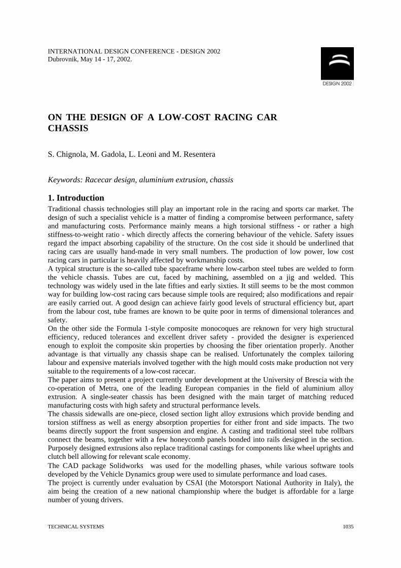
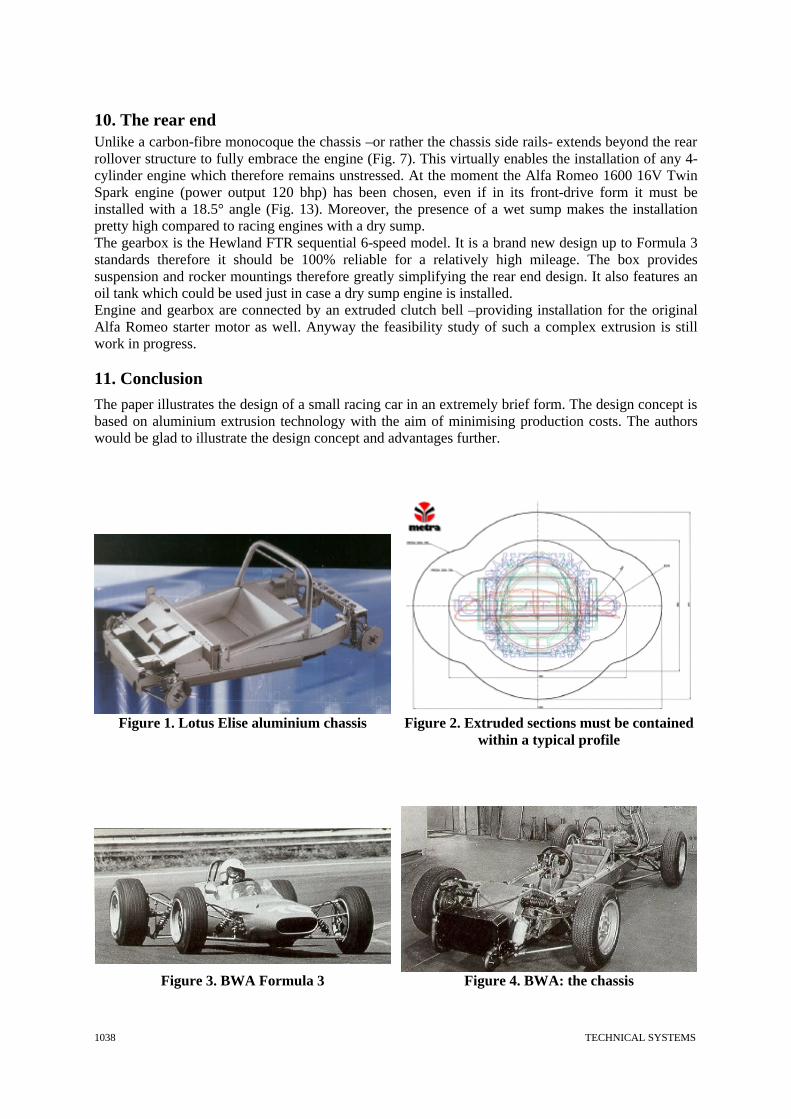
2. The design concept In the early nineties Lotus designed a truly innovative sportscar, the Elise. Its chassis is entirely composed by bonded aluminium extrusions (Fig. 1). This technology was said to suit very well the needs of a low-volume production car, where traditional steel sheet pressing is simply prohibitive. But the idea of building a sports vehicle with simple extrusions was born much earlier: a tiny racecar called BWA was designed and manufactured by Giorgio Valentini from 1963 to ’66 (Fig. 3). The chassis was composed by two main rectangular extruded beams (Fig. 4). This car has recently been defined “the simplest and probably cheaper racecar built in the last fourty years” by Gianpaolo Dallara, the world known Italian racing car manufacturer [Dallara 2001]. This very basic concept has been re-examined with the aim of exploiting scale economy allowed by current extrusion technologies; the vehicle chassis is therefore made of two one-piece side rails which provide most of the structural performance required. Also other bits and pieces are extruded and even traditional castings like uprights and clutch bell are manufactured from extruded sections.
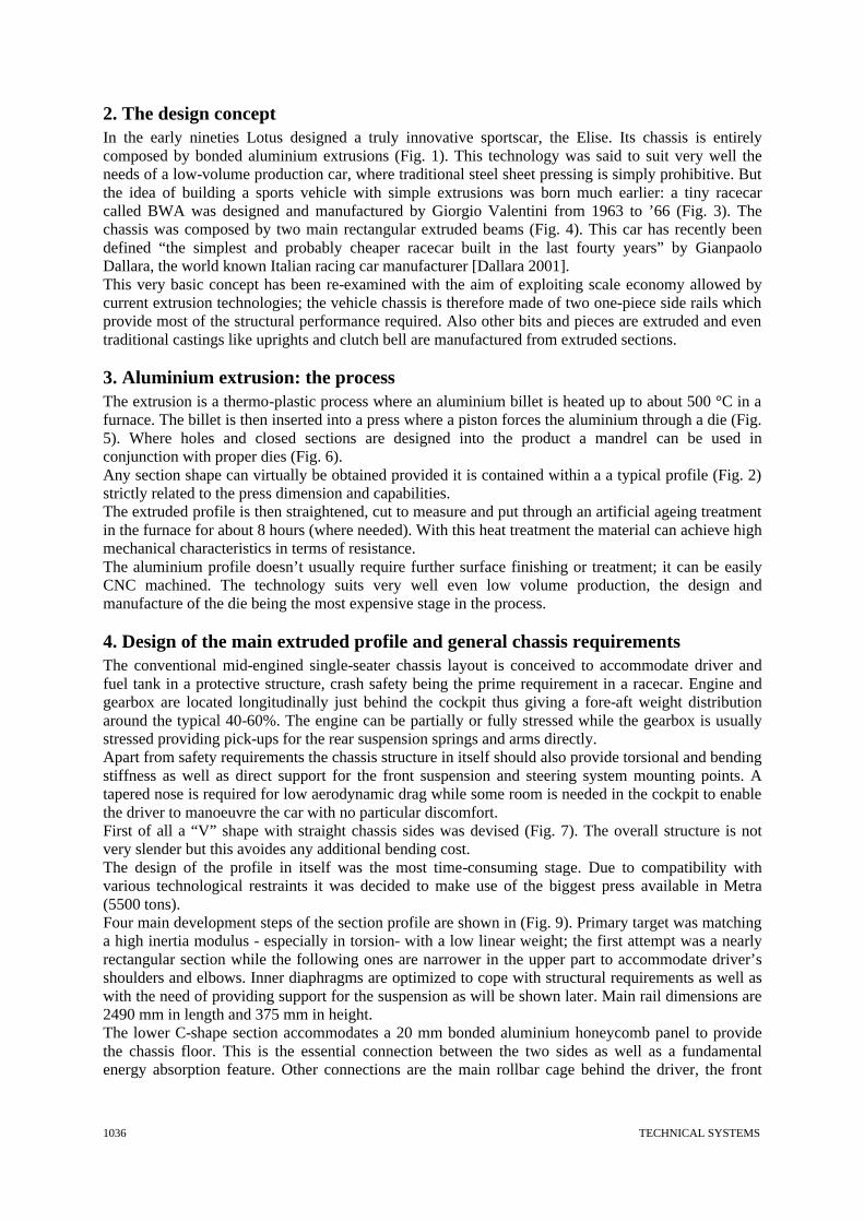
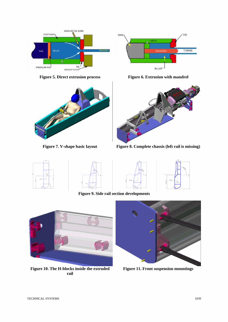
3. Aluminium extrusion: the process The extrusion is a thermo-plastic process where an aluminium billet is heated up to about 500 °C in a furnace. The billet is then inserted into a press where a piston forces the aluminium through a die (Fig. 5). Where holes and closed sections are designed into the product a mandrel can be used in conjunction with proper dies (Fig. 6). Any section shape can virtually be obtained provided it is contained within a a typical profile (Fig. 2) strictly related to the press dimension and capabilities. The extruded profile is then straightened, cut to measure and put through an artificial ageing treatment in the furnace for about 8 hours (where needed). With this heat treatment the material can achieve high mechanical characteristics in terms of resistance. The aluminium profile doesn’t usually require further surface finishing or treatment; it can be easily CNC machined. The technology suits very well even low volume production, the design and manufacture of the die being the most expensive stage in the process.
4. Design of the main extruded profile and general chassis requirements The conventional mid-engined single-seater chassis layout is conceived to accommodate driver and fuel tank in a protective structure, crash safety being the prime requirement in a racecar. Engine and gearbox are located longitudinally just behind the cockpit thus giving a fore-aft weight distribution around the typical 40-60%. The engine can be partially or fully stressed while the gearbox is usually stressed providing pick-ups for the rear suspension springs and arms directly. Apart from safety requirements the chassis structure in itself should also provide torsional and bending stiffness as well as direct support for the front suspension and steering system mounting points. A tapered nose is required for low aerodynamic drag while some room is needed in the cockpit to enable the driver to manoeuvre the car with no particular discomfort. First of all a “V” shape with straight chassis sides was devised (Fig. 7). The overall structure is not very slender but this avoides any additional bending cost. The design of the profile in itself was the most time-consuming stage. Due to compatibility with various technological restraints it was decided to make use of the biggest press available in Metra (5500 tons). Four main development steps of the section profile are shown in (Fig. 9). Primary target was matching a high inertia modulus - especially in torsion- with a low linear weight; the first attempt was a nearly rectangular section while the following ones are narrower in the upper part to accommodate driver’s shoulders and elbows. Inner diaphragms are optimized to cope with structural requirements as well as with the need of providing support for the suspension as will be shown later. Main rail dimensions are 2490 mm in length and 375 mm in height. The lower C-shape section accommodates a 20 mm bonded aluminium honeycomb panel to provide the chassis floor. This is the essential connection between the two sides as well as a fundamental energy absorption feature. Other connections are the main rollbar cage behind the driver, the front

TECHNICAL SYSTEMS 1037
rollbar, the front suspension casting, a secondary transverse beam under the driver’s knees and the front and rear end panels (Fig. 8).
5. Structural analysis According to numerical results the chassis turned out to be quite stiff in torsion. Again, vital components as well as the whole chassis have been FEM verified by simulating typical events (maximum G cornering and braking, jump on a kerb etc). A future paper will be published on this topic.
6. Design of the safety structures According to FIA (Federation Internationale de l’Automobile) standards any single-seater must be equipped with a steel tube structure capable of standing the following set of forces at the same time in the unlucky event of a rollover:
• 7.5 w, vertical • 5.5 w, longitudinal • 1.5 w, transverse
where w is the weight of the running vehicle. In this case the structure is manufactured from welded 25CrMo4 steel tube; it is conceived to become a stressed part of the chassis by connecting the sides, floor and engine and to provide a full torsion box behind the driver. The fuel tank is located inside this box. The roll over structure has been FEM verified to comply with FIA standards. Apart from rollover protection, the similar front tube structure provides support to the steering wheel, the dashboard, the front springs and to the front suspension by bracing the casting.
7. Pick-up points Various point loads -primarily suspension forces- are fed into the chassis. It is therefore necessary to spread these loads by involving the side section as a whole; local stiffness is effectively vital to achieve predictable handling characteristics just like allover stiffness. A modular system based on an extruded H-section has been designed with this aim. This profile is sliced into different thickness blocks (referred to as H-blocks, Fig. 10) and inserted through the main side rails. Four M8 bolts connect the side rail walls and the H-blocks to actually spread the point loads on a large area. Suspension ball joints are pressed into the H-block therefore they are positioned inside the main rail. Suspension wishbones carry end forks and run through small openings in the rail wall as shown in Fig. 11.
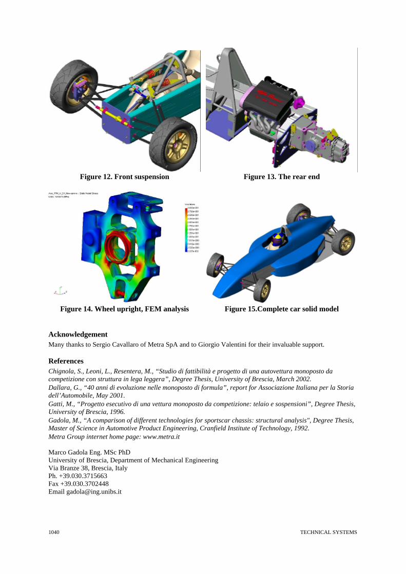
8. Suspension system Both front and rear suspension systems are quite conventional. They are fully adjustable, double wishbone geometries. Coilover dampers are actuated via pushrods and rockers, while anti-roll bars are adjustable T-blades. At the front, the above mentioned casting supports rockers and anti-roll bar. It shares the chassis mounting H-blocks with the upper suspension arms (Fig. 12). The rear geometry must cope with the high-mounted gearbox (see paragraph n. 10).
9. Wheel uprights Extruded uprights have been designed to replace traditional castings or fabricated steel sheet components. Front and rear uprights are exactly the same shape and extrusion thickness, while machining can be kept down to a minimum to cut costs. According to FEM analysis the structural performance is up to the standard required for such a type of racing car (Fig. 14).
TECHNICAL SYSTEMS 1038
10. The rear end Unlike a carbon-fibre monocoque the chassis –or rather the chassis side rails- extends beyond the rear rollover structure to fully embrace the engine (Fig. 7). This virtually enables the installation of any 4-cylinder engine which therefore remains unstressed. At the moment the Alfa Romeo 1600 16V Twin Spark engine (power output 120 bhp) has been chosen, even if in its front-drive form it must be installed with a 18.5° angle (Fig. 13). Moreover, the presence of a wet sump makes the installation pretty high compared to racing engines with a dry sump. The gearbox is the Hewland FTR sequential 6-speed model. It is a brand new design up to Formula 3 standards therefore it should be 100% reliable for a relatively high mileage. The box provides suspension and rocker mountings therefore greatly simplifying the rear end design. It also features an oil tank which could be used just in case a dry sump engine is installed. Engine and gearbox are connected by an extruded clutch bell –providing installation for the original Alfa Romeo starter motor as well. Anyway the feasibility study of such a complex extrusion is still work in progress.
11. Conclusion The paper illustrates the design of a small racing car in an extremely brief form. The design concept is based on aluminium extrusion technology with the aim of minimising production costs. The authors would be glad to illustrate the design concept and advantages further.
Figure 1. Lotus Elise aluminium chassis Figure 2. Extruded sections must be contained
within a typical profile
Figure 3. BWA Formula 3 Figure 4. BWA: the chassis
TECHNICAL SYSTEMS 1039
Figure 5. Direct extrusion process Figure 6. Extrusion with mandrel
Figure 7. V-shape basic layout
Figure 8. Complete chassis (left rail is missing)
Figure 9. Side rail section developments
Figure 10. The H-blocks inside the extruded
rail Figure 11. Front suspension mountings
TECHNICAL SYSTEMS 1040
Figure 12. Front suspension
Figure 13. The rear end
Figure 14. Wheel upright, FEM analysis Figure 15.Complete car solid model
Acknowledgement Many thanks to Sergio Cavallaro of Metra SpA and to Giorgio Valentini for their invaluable support.
References Chignola, S., Leoni, L., Resentera, M., “Studio di fattibilità e progetto di una autovettura monoposto da competizione con struttura in lega leggera”, Degree Thesis, University of Brescia, March 2002. Dallara, G., “40 anni di evoluzione nelle monoposto di formula”, report for Associazione Italiana per la Storia dell’Automobile, May 2001. Gatti, M., “Progetto esecutivo di una vettura monoposto da competizione: telaio e sospensioni”, Degree Thesis, University of Brescia, 1996. Gadola, M., “A comparison of different technologies for sportscar chassis: structural analysis", Degree Thesis, Master of Science in Automotive Product Engineering, Cranfield Institute of Technology, 1992. Metra Group internet home page: www.metra.it Marco Gadola Eng. MSc PhD University of Brescia, Department of Mechanical Engineering Via Branze 38, Brescia, Italy Ph. +39.030.3715663 Fax +39.030.3702448 Email [email protected]