on the fundamental mechanism of seam welding in extrusion of aluminum alloys
TRANSCRIPT
On the fundamental mechanism of seam welding in extrusion of aluminum alloys
Henry Valberg1, a and Yawar Abbas Khan1,b 1Norwegian University of Science and Technology, Department of Engineering Design and
Materials, Richard Birkelands v. 2B, 7491 Trondheim, Norway.
ahenry.valberg @ntnu.no, [email protected]
Keywords: Extrusion seam welding, Pressure welding, Mechanism of welding
Abstract. In extrusion of hollow Al-profiles two kinds of pressure welds are present inside the extrusion.
One is called the charge weld (CW) and forms across the boundary interface between two billets
extruded in sequence. The other is the seam weld (SW) which extends longitudinally along the
extruded profile and the extrusion metal behind each die bridge. It is considered to form because of
the splitting of the extrusion metal over the die bridge into metal streams which flow past the bridge
and rejoin as they encounter behind the bridge.
Over the time attempts have been made to explain the mechanics of extrusion welding for both
the CW and the SW. Still there is lack of understanding of how these welds form, the main reasons
for this is that the deformation conditions around a die bridge are complex and difficult to
investigate.
Because of the recent advancement of two technological fields, experimental grid pattern
analysis and simulation of metal flow by FEA; new tools for analysis of the mechanics of formation
of the SW and the CW are now available. The simplest possible case of 2D-extrusion seam welding
is considered here and an attempt is made to describe the fundamental deformation mechanisms
present when this weld forms behind a butt-ended die bridge.
Introduction
In the beginning of an extrusion process [1] through a porthole die the CW inside the extrusion
will have inferior quality as there is only partial joining across the interface between the two billets
extruded after each other. Because of this, a short piece from the extruded profile containing the
first part of the CW is cut away and discarded. Later during extrusion the CW becomes as good as
the parent material of the extrusion outside the weld and does not represent any weakness inside the
extrusion.
Most commonly the SW will also be good [1], and as for the CW, it will not represent any
weakness in the profile. However, if process conditions are not set properly, or contamination is
trapped behind the bridge and flows out into the SW, an inferior SW may form.
Metal flow around a die bridge and into the weld chamber behind it, has been studied at various
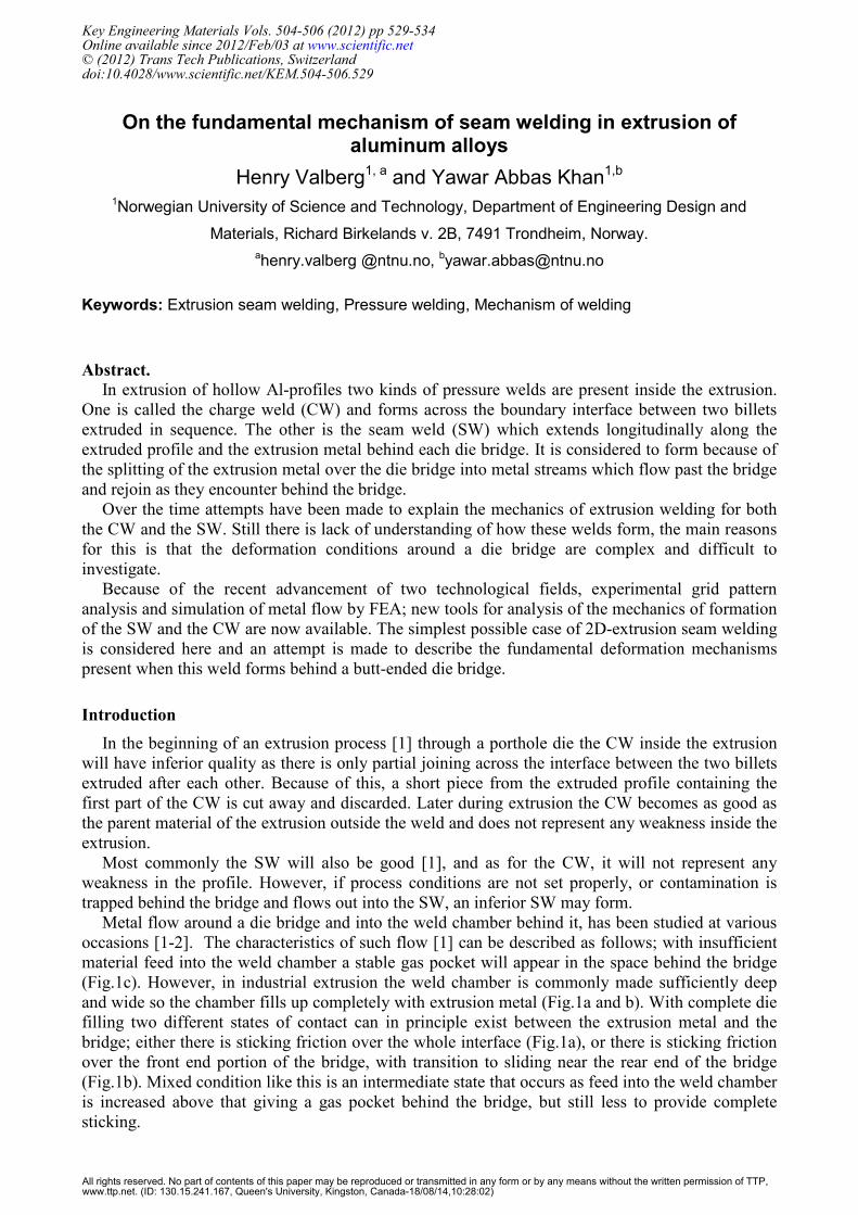
occasions [1-2]. The characteristics of such flow [1] can be described as follows; with insufficient
material feed into the weld chamber a stable gas pocket will appear in the space behind the bridge
(Fig.1c). However, in industrial extrusion the weld chamber is commonly made sufficiently deep
and wide so the chamber fills up completely with extrusion metal (Fig.1a and b). With complete die
filling two different states of contact can in principle exist between the extrusion metal and the
bridge; either there is sticking friction over the whole interface (Fig.1a), or there is sticking friction
over the front end portion of the bridge, with transition to sliding near the rear end of the bridge
(Fig.1b). Mixed condition like this is an intermediate state that occurs as feed into the weld chamber
is increased above that giving a gas pocket behind the bridge, but still less to provide complete
sticking.
Key Engineering Materials Vols. 504-506 (2012) pp 529-534Online available since 2012/Feb/03 at www.scientific.net© (2012) Trans Tech Publications, Switzerlanddoi:10.4028/www.scientific.net/KEM.504-506.529
All rights reserved. No part of contents of this paper may be reproduced or transmitted in any form or by any means without the written permission of TTP,www.ttp.net. (ID: 130.15.241.167, Queen's University, Kingston, Canada-18/08/14,10:28:02)
a) b) c)
Figure 1. Possible situations of metal flow and boundary contact around an extrusion bridge.
Experimental studies of metal flow around a bridge with butt back-end shape
Some of the first experimental studies of metal flow in extrusion around a bridge are due to
Akeret [2]. Later this phenomenon has been investigated using grid pattern techniques based on
insertion of contrast pins [4] into holes drilled into a billet [4-8]. This technique allows a detailed
characterization of the nature of the shear zones inside the metal as the applied grid pattern does not
erase in the layers subjected to heavy deformations.
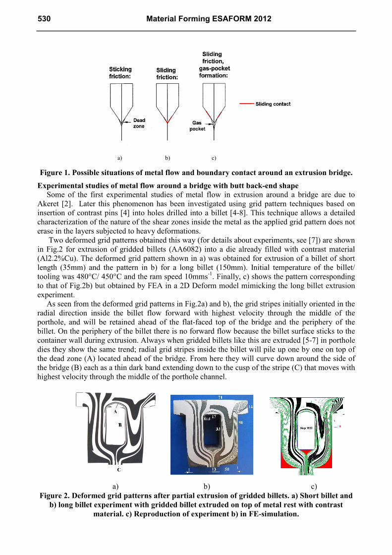
Two deformed grid patterns obtained this way (for details about experiments, see [7]) are shown
in Fig.2 for extrusion of gridded billets (AA6082) into a die already filled with contrast material
(Al2.2%Cu). The deformed grid pattern shown in a) was obtained for extrusion of a billet of short
length (35mm) and the pattern in b) for a long billet (150mm). Initial temperature of the billet/
tooling was 480°C/ 450°C and the ram speed 10mms-1. Finally, c) shows the pattern corresponding
to that of Fig.2b) but obtained by FEA in a 2D Deform model mimicking the long billet extrusion
experiment.
As seen from the deformed grid patterns in Fig.2a) and b), the grid stripes initially oriented in the
radial direction inside the billet flow forward with highest velocity through the middle of the
porthole, and will be retained ahead of the flat-faced top of the bridge and the periphery of the
billet. On the periphery of the billet there is no forward flow because the billet surface sticks to the
container wall during extrusion. Always when gridded billets like this are extruded [5-7] in porthole
dies they show the same trend; radial grid stripes inside the billet will pile up one by one on top of
the dead zone (A) located ahead of the bridge. From here they will curve down around the side of
the bridge (B) each as a thin dark band extending down to the cusp of the stripe (C) that moves with
highest velocity through the middle of the porthole channel.
a) b) c) Figure 2. Deformed grid patterns after partial extrusion of gridded billets. a) Short billet and
b) long billet experiment with gridded billet extruded on top of metal rest with contrast
material. c) Reproduction of experiment b) in FE-simulation.
530 Material Forming ESAFORM 2012
(a)
(b)
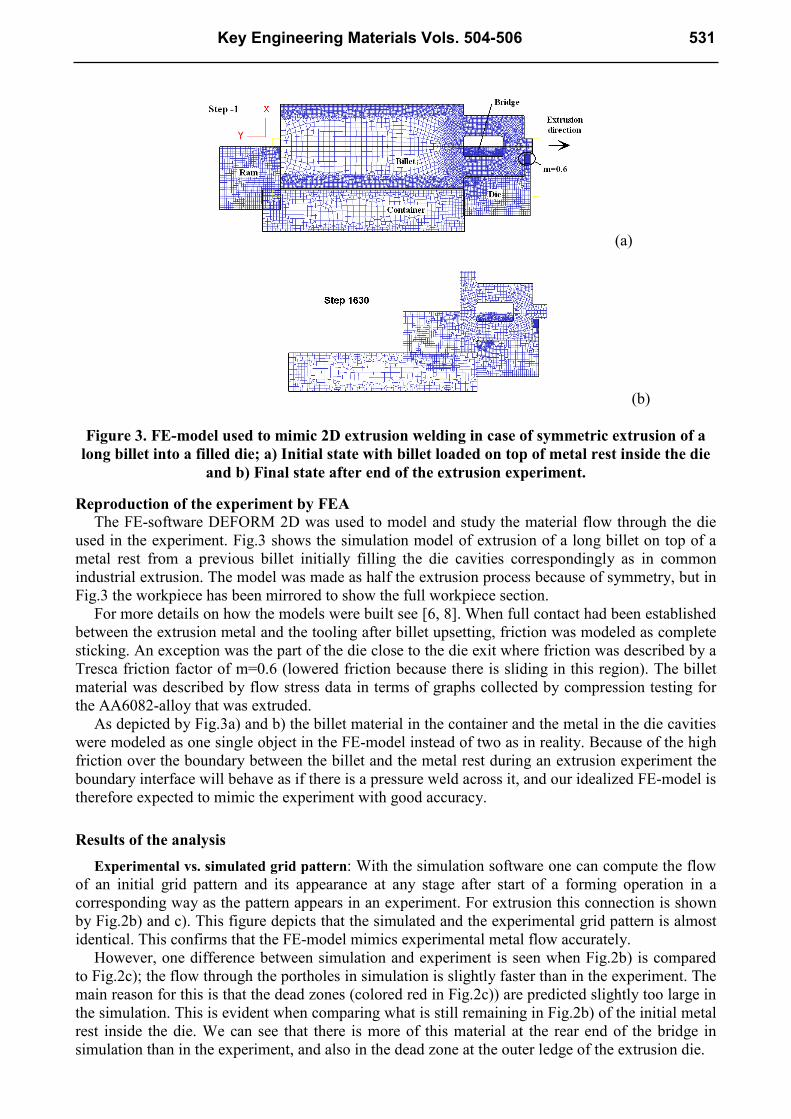
Figure 3. FE-model used to mimic 2D extrusion welding in case of symmetric extrusion of a
long billet into a filled die; a) Initial state with billet loaded on top of metal rest inside the die
and b) Final state after end of the extrusion experiment.
Reproduction of the experiment by FEA
The FE-software DEFORM 2D was used to model and study the material flow through the die
used in the experiment. Fig.3 shows the simulation model of extrusion of a long billet on top of a
metal rest from a previous billet initially filling the die cavities correspondingly as in common
industrial extrusion. The model was made as half the extrusion process because of symmetry, but in
Fig.3 the workpiece has been mirrored to show the full workpiece section.
For more details on how the models were built see [6, 8]. When full contact had been established
between the extrusion metal and the tooling after billet upsetting, friction was modeled as complete
sticking. An exception was the part of the die close to the die exit where friction was described by a
Tresca friction factor of m=0.6 (lowered friction because there is sliding in this region). The billet
material was described by flow stress data in terms of graphs collected by compression testing for
the AA6082-alloy that was extruded.
As depicted by Fig.3a) and b) the billet material in the container and the metal in the die cavities
were modeled as one single object in the FE-model instead of two as in reality. Because of the high
friction over the boundary between the billet and the metal rest during an extrusion experiment the
boundary interface will behave as if there is a pressure weld across it, and our idealized FE-model is
therefore expected to mimic the experiment with good accuracy.
Results of the analysis
Experimental vs. simulated grid pattern: With the simulation software one can compute the flow
of an initial grid pattern and its appearance at any stage after start of a forming operation in a
corresponding way as the pattern appears in an experiment. For extrusion this connection is shown
by Fig.2b) and c). This figure depicts that the simulated and the experimental grid pattern is almost
identical. This confirms that the FE-model mimics experimental metal flow accurately.
However, one difference between simulation and experiment is seen when Fig.2b) is compared
to Fig.2c); the flow through the portholes in simulation is slightly faster than in the experiment. The
main reason for this is that the dead zones (colored red in Fig.2c)) are predicted slightly too large in
the simulation. This is evident when comparing what is still remaining in Fig.2b) of the initial metal
rest inside the die. We can see that there is more of this material at the rear end of the bridge in
simulation than in the experiment, and also in the dead zone at the outer ledge of the extrusion die.
Key Engineering Materials Vols. 504-506 531
a) b) c)
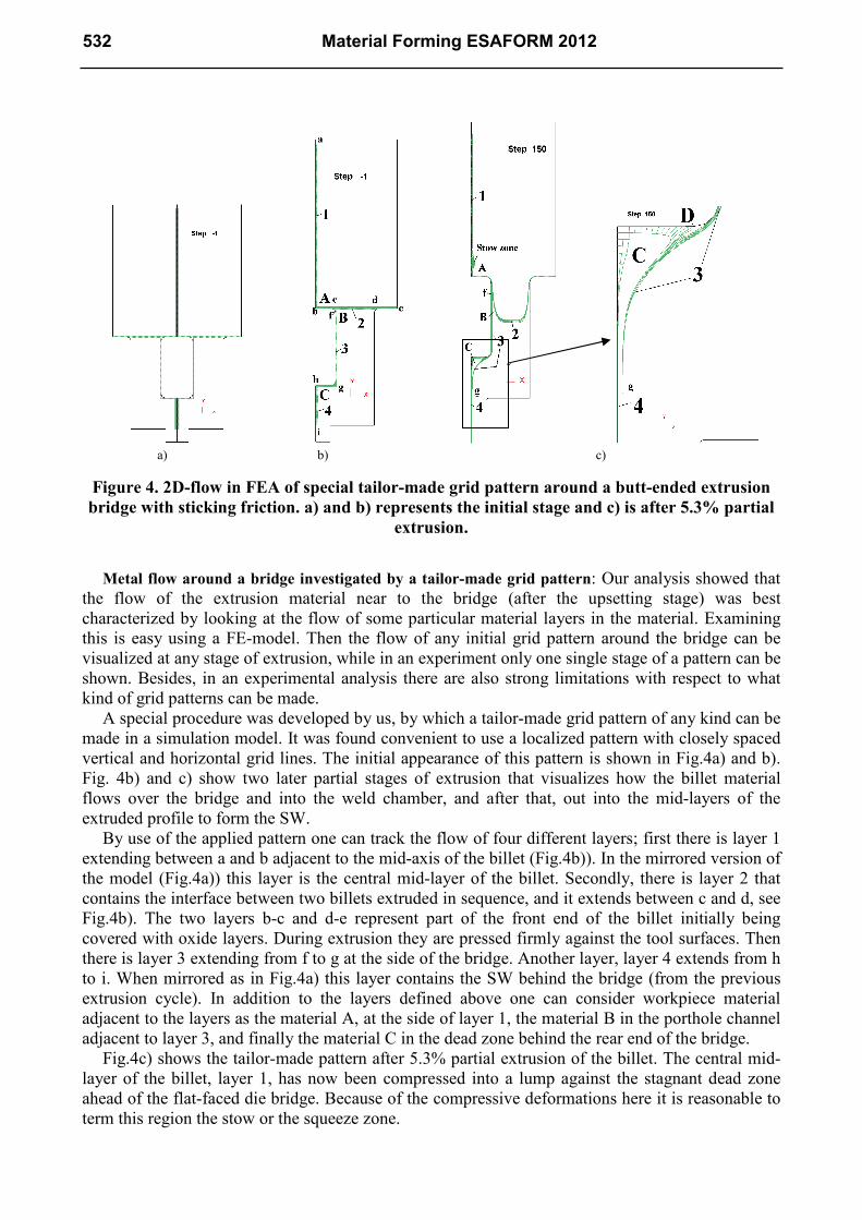
Figure 4. 2D-flow in FEA of special tailor-made grid pattern around a butt-ended extrusion
bridge with sticking friction. a) and b) represents the initial stage and c) is after 5.3% partial
extrusion.
Metal flow around a bridge investigated by a tailor-made grid pattern: Our analysis showed that
the flow of the extrusion material near to the bridge (after the upsetting stage) was best
characterized by looking at the flow of some particular material layers in the material. Examining
this is easy using a FE-model. Then the flow of any initial grid pattern around the bridge can be
visualized at any stage of extrusion, while in an experiment only one single stage of a pattern can be
shown. Besides, in an experimental analysis there are also strong limitations with respect to what
kind of grid patterns can be made.
A special procedure was developed by us, by which a tailor-made grid pattern of any kind can be
made in a simulation model. It was found convenient to use a localized pattern with closely spaced
vertical and horizontal grid lines. The initial appearance of this pattern is shown in Fig.4a) and b).
Fig. 4b) and c) show two later partial stages of extrusion that visualizes how the billet material
flows over the bridge and into the weld chamber, and after that, out into the mid-layers of the
extruded profile to form the SW.
By use of the applied pattern one can track the flow of four different layers; first there is layer 1
extending between a and b adjacent to the mid-axis of the billet (Fig.4b)). In the mirrored version of
the model (Fig.4a)) this layer is the central mid-layer of the billet. Secondly, there is layer 2 that
contains the interface between two billets extruded in sequence, and it extends between c and d, see
Fig.4b). The two layers b-c and d-e represent part of the front end of the billet initially being
covered with oxide layers. During extrusion they are pressed firmly against the tool surfaces. Then
there is layer 3 extending from f to g at the side of the bridge. Another layer, layer 4 extends from h
to i. When mirrored as in Fig.4a) this layer contains the SW behind the bridge (from the previous
extrusion cycle). In addition to the layers defined above one can consider workpiece material
adjacent to the layers as the material A, at the side of layer 1, the material B in the porthole channel
adjacent to layer 3, and finally the material C in the dead zone behind the rear end of the bridge.
Fig.4c) shows the tailor-made pattern after 5.3% partial extrusion of the billet. The central mid-
layer of the billet, layer 1, has now been compressed into a lump against the stagnant dead zone
ahead of the flat-faced die bridge. Because of the compressive deformations here it is reasonable to
term this region the stow or the squeeze zone.
532 Material Forming ESAFORM 2012
Layer 2 containing the charge weld has been deformed into U-shape with one end (c) attached to the edge of the bridge and the other (d) to the edge of the die. Along the side of the bridge layer 3 has become thinner due to shearing and the end g of it has flown forward and appears as the tip of a tongue close to the SW. Layer 4 (initially the SW in the weld chamber from the previous billet) has stretched out and has flown through the die exit to become the SW of the extrusion. Close to the rear end of the bridge this layer still remains in the dead zone - and as extrusion proceeds - it seeps out gradually into the SW. In addition material from the dead zone (C) has flown forward as a thin layer in between layer 3 and 4.
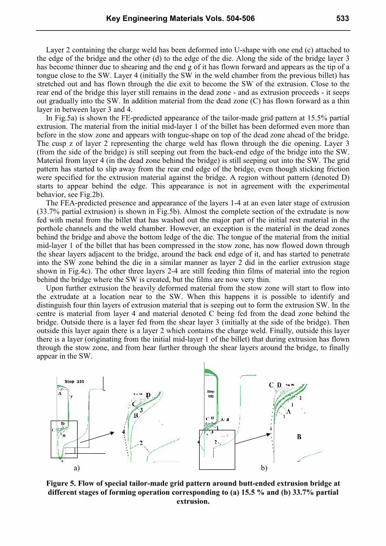
In Fig.5a) is shown the FE-predicted appearance of the tailor-made grid pattern at 15.5% partial extrusion. The material from the initial mid-layer 1 of the billet has been deformed even more than before in the stow zone and appears with tongue-shape on top of the dead zone ahead of the bridge. The cusp z of layer 2 representing the charge weld has flown through the die opening. Layer 3 (from the side of the bridge) is still seeping out from the back-end edge of the bridge into the SW. Material from layer 4 (in the dead zone behind the bridge) is still seeping out into the SW. The grid pattern has started to slip away from the rear end edge of the bridge, even though sticking friction were specified for the extrusion material against the bridge. A region without pattern (denoted D) starts to appear behind the edge. This appearance is not in agreement with the experimental behavior, see Fig.2b).
The FEA-predicted presence and appearance of the layers 1-4 at an even later stage of extrusion (33.7% partial extrusion) is shown in Fig.5b). Almost the complete section of the extrudate is now fed with metal from the billet that has washed out the major part of the initial rest material in the porthole channels and the weld chamber. However, an exception is the material in the dead zones behind the bridge and above the bottom ledge of the die. The tongue of the material from the initial mid-layer 1 of the billet that has been compressed in the stow zone, has now flowed down through the shear layers adjacent to the bridge, around the back end edge of it, and has started to penetrate into the SW zone behind the die in a similar manner as layer 2 did in the earlier extrusion stage shown in Fig.4c). The other three layers 2-4 are still feeding thin films of material into the region behind the bridge where the SW is created, but the films are now very thin.
Upon further extrusion the heavily deformed material from the stow zone will start to flow into the extrudate at a location near to the SW. When this happens it is possible to identify and distinguish four thin layers of extrusion material that is seeping out to form the extrusion SW. In the centre is material from layer 4 and material denoted C being fed from the dead zone behind the bridge. Outside there is a layer fed from the shear layer 3 (initially at the side of the bridge). Then outside this layer again there is a layer 2 which contains the charge weld. Finally, outside this layer there is a layer (originating from the initial mid-layer 1 of the billet) that during extrusion has flown through the stow zone, and from hear further through the shear layers around the bridge, to finally appear in the SW.
a) b)
Figure 5. Flow of special tailor-made grid pattern around butt-ended extrusion bridge at
different stages of forming operation corresponding to (a) 15.5 % and (b) 33.7% partial
extrusion.
Key Engineering Materials Vols. 504-506 533
Discussion
The reader has perhaps already noticed that the thicknesses of the layers 1-4 defined inside the
billet material were chosen arbitrarily. If other thicknesses had been chosen, the stage at which each
layer penetrates into the SW would differ from that obtained here. Nevertheless, the sequence of
appearance in the SW of these layers of extrusion material of different origin, would be the same,
only the instant when they appear in the SW would differ.
The analysis shows that the layers 2-4 thin out strongly when 1/3rd of the billet has been extruded
and that at this instant the mid-layer 1 from the stow zone starts to appear near (or in) the SW. At
the 1/3rd stage one can again consider new layers 1-4 introduced close to the bridge in the same
manner as for the initial stage of extrusion (see Fig.4b), and on further running of the process up to
2/3rds full extrusion, these new layers would flow out into the SW in the same manner as the
corresponding initially defined layers did during the first 1/3rd of the process. And the same
procedure can be repeated once more, a third time, until the whole billet has been extruded. This
way of reasoning gives a good picture of how strongly the material flowing around the bridge is
deforming.
Conclusion
By comparison of FE-modeled and experimental grid patterns in 2D-extrusion it is shown that
FE-simulated metal flow describes the real flow in the experiment accurately.
By using a tailor-made grid-pattern built-up of four different layers inside the extrusion material
it has been possible to determine how these layers flow over the die bridge to form corresponding
layers in the seam weld. A new flow phenomena has been identified; as the analysis reveals that an
initial thin layer of material from close to the mid-axis of the billet, becomes heavily compressed
against the dead zone ahead of the bridge (in the stow zone), before it subsequently deforms more in
shear as it flows through the shear zones at the side of the bridge. Finally, this material will appear
near to the seam weld as a very heavily deformed layer.
References
[1] H. Valberg, “Extrusion welding in aluminium extrusion”, Int. J. of Materials & Product
Technology, Vol.17, No.7, 2002, pp. 497-556.
[2] R. Akeret, “Extrusion Welds-quality aspects are now center stage”. 5th Int. Al Extrusion
Technology Seminar, Vol 1, 1992, pp. 319-336.
[3] H. S. Valberg, “Applied metal forming; including FEM analysis”, 1st Ed, Cambridge
University Press, NY, USA, 2010.
[4] A. Smaabrekke, “Verification of simulation results by Forge2”, MSc.-thesis, NTNU, 1992, (in
Norwegian).
[5] T. Welo, A. Smaabrekke and H. Valberg, "Two-dimensional simulation of porthole extrusion",
Aluminium, Vol.71, no.1, 1995, pp. 90-94.
[6] H. Valberg; Y. A. Khan and P. T. Moe, “The mechanics of two-dimensional extrusion welding
investigated by FEM-analysis with experiment”, Proc. 9th Int. Conf. on Technol. of Plasticity“,
Gyeongju, Korea.
[7] F. Hagemann, “Metal flow in porthole extrusion; Simulation and verifying experiment”, Project
report, NTNU, Trondheim, 1995.
[8] Y. A. Khan, H. Valberg and I. Irgens, “Joining of metal streams in extrusion welding”, Int. J.
Mater. Form., 2009, Suppl. 1, pp. 109-112.
534 Material Forming ESAFORM 2012

Material Forming ESAFORM 2012 10.4028/www.scientific.net/KEM.504-506 On the Fundamental Mechanism of Seam Welding in Extrusion of Aluminum Alloys 10.4028/www.scientific.net/KEM.504-506.529