on the radiation patterns of common emc antennas · 2013-09-16 · transition from the transmission...
TRANSCRIPT

34 interference technology emc Directory & Design guiDe 2011
testing & test equipment On the Radiat iOn Pat teRns Of COmmOn emC antennas
Vicente RodRiguezets-lindgren l.P. cedar Park, texas usA
Antennas have been used in EMC measurements since the early days. Knowledge of the antenna pattern
was not a requirement of the standards. While MIL STD 461 and some SAE stan-dards called for information on the half power beamwidth, most standards did not require any knowledge of the antenna radia-tion characteristics. With the evolution of standards to cover frequencies above 1 GHz knowledge of the pattern has become more important. Since above 1 GHz most antennas are very directive and very un-dipole-like, information on the pattern has become very important, especially when it comes to un-derstanding how much area the main beam is covering. The present paper starts by giv-ing the reader a refresher on antenna pattern parameters and then shows typical patterns for the most common antennas used in EMC. The antennas covered are biconicals, log periodic dipole arrays, hybrid antennas and dual ridge horns. Measured data is presented except for patterns above 18 GHz.
intRoductionAn antenna is a device that radiates and receives radio waves. There are different methods or mechanisms by which antennas radiate. We all are familiar with resonator antennas. Dipoles are a clear example of this type on antennas. In resonant antennas there is a movement of charges as the en-ergy changes between the electric field and the magnetic field. This movement of the charges on the antenna causes the field lines to vibrate, generating waves that propagate in free space away from the resonant an-tenna. Figure 1 shows this type of behavior. Another mechanism by which antennas radiate is by having an impedance transition that causes the energy being propagated in a transmission line to be launched into free space. Horn antennas are an example of a travelling wave antenna. Their method for radiation is based on a wave impedance transition from the transmission waveguide or line to the impedance of free space. Fig-ure 2 shows this mechanism of radiation on a horn antenna.
RAdiAtion PAtteRnSAn antenna radiation pattern or antenna pattern is a mathematical function or a graphical representation of the radiation properties of the antenna as a function of space coordinates [1]. That is, as we rotate the antenna around on two orthogonal axes we measure the intensity of the radiated field. Figure 3 shows one of these plots of magnitude of radiation versus direction.
e and H planeWhile today it is really easy to create pat-
on the Radiation Patterns of common eMc Antennas
Figure 1. A modified shaped dipole (biconical) radiating; example of a resonant antenna.
All photos used with permission of ETS-Lindgren
2011 emC diReCtORy & design guide, may 2011

ROdRiguez
interferencetechnology.com interference technology 35
testing & test equipment
terns such as the one in Figure 3 and to manipulate them on the computer, this was not the case in the earlier days of antenna engineering. Hence, to fa-cilitate the graphical representation of radiation patterns, engineers usually plotted two single orthogonal planes of the pattern. Rather than arbitrarily plot a plane for a given angle of the spheri-cal coordinate system (for example
φ=90o), engineers chose the plane on which the Electric field was oscillating. This plane was called the E plane. The orthogonal plane to this one was named the H-plane. Even today patterns are commonly shown in E and H planes in the literature.
omnidirectional and directional Like many other things in nature, the
human brain likes to classify things to make it easier to study them. Radiation patterns are no different. One of the first divisions that we can do is to break patterns into two principal groups: Directional and Omnidirectional pat-terns. Omnidirectional comes from the Latin word omni meaning “every” or “all” and “direction”. These, it ap-pears, are patterns that radiate in all directions. That is not exactly it. Om-nidirectional antennas, which radiate omnidirectional patterns, radiate in all directions on a given principal plane (the E or the H plane. Figure 4 shows the most simple of all omnidirectional antennas, the dipole. The dipole radi-ates in all directions on the H plane, but it has two nulls (areas of little or no radiation) on the E plane.
Omnidirectional should not be confused with isotropic. Isotropic (from the Greek, isos meaning “the same” or “equal” and tropos meaning “direction”) implies that the radiator puts exactly the same radiation in all directions around it. There is no such thing as an isotropic antenna. A com-bination of three dipole-like antennas may have certain isotropicity, but it will never be a perfect isotropic source. Isotropic sources are a mathematical tool that is used in describing the gain of antennas. Directional antennas are clearly antennas where the radiation is mainly on one direction as we rotate around the antenna.
Main lobe, side lobes, back lobe We now continue our human approach to classify things to make them easier to study. If we look at a radiation pat-tern we observe a series of features. There is going to be an area of the pattern where most of the radiation is directed. That is the main lobe. To the sides of the main lobe we may find areas where the radiation is higher than the adjacent areas. These are side lobes. The side lobes are usually sepa-rated by areas of little radiation called nulls. There is usually a side lobe in the direction opposite the main lobe. This special side lobe is known as the back lobe. Figure 5 shows a pattern and the features described above.
Figure 2. A pyramidal horn radiating; a sample of an impedance transition between the transmission line and free space.
Figure 3. A horn antenna and its radiation pattern at a given frequency.
Figure 4. Omnidirectional antenna.
2011 emC diReCtORy & design guide, may 2011

36 interference technology emc Directory & Design guiDe 2011
testing & test equipment On the Radiat iOn Pat teRns Of COmmOn emC antennas
Half power beam widthIt should be clear that the most impor-tant lobe is the main lobe. After all, the main lobe contains most of the radi-ated energy. This does not mean that the other lobes are irrelevant. The back lobe should be small. We do not want to send too much radiation towards the back. This is especially important during immunity at frequencies above 1 GHz, when usually the amplifiers are placed inside the chamber close to the antenna to reduce cable losses. Side lobes are also important; high side lobes illuminating the sides of a cham-ber will affect the field uniformity if the absorber treatment is not adequate. Outside of EMC these parameters of the patterns are even more important.
But clearly, as mentioned above, the main lobe is the most important as it is the one that should encompass the EUT. The parameter that describes the main lobe size is the half power beamwidth. Since 1/2 is 0.5 and 10Log10 (0.5) ≈-3dB, the half power beamwidth (HPBW) is also known as the 3dB beam width. The HPBW is given in degrees and it describes the arc of the angle between the two points to the side of the point of highest radiation that are 3dB lower in radiated power. Figure 6 shows the half power beamwidth for the pattern shown in Figure 5. For clarity, the pattern is represented in Cartesian coordinates rather than po-lar coordinates. It is important to note that the HPBW is from -3dB point to -3dB point not from -3dB point to peak.
Manufacturers should supply the HPBW information to users of their antennas. The HPBW will be given for the E and H plane. For a linearly
polarized antenna, the E plane will be vertical when the antenna is on verti-cal polarization. When the antenna is rotated to horizontal polarization, the E plane will be horizontal. Similarly the H plane will be horizontal when the an-tenna is set for vertical polarization and the H plane will be vertical when the antenna is on horizontal polarization.
Another important issue is that the HPBW, like any other pattern param-eter, is a free space, far field param-eters. The beamwidth will give you an idea of the area covered, but in some cases structures in the test area such as grounded benches and ground planes will affect the radiation pattern and the beamwidth. Figures 7 and 8 show a log periodic antenna placed on horizontal polarization radiation 1 meter away from a bench. This is a common set up in CISPR 25 and other standards [2-4].
So the user must be careful when us-ing the HPBW extracted from the pat-tern to estimate the area of coverage of the main beam. In some cases, such as the new set up from above 1GHz test-ing [5], it will provide a good estimate. In other cases, such as in the presence of benches and other features, it will be better to use field probes to estimate the coverage of the main beam.
PAtteRn MeASuReMentSAs mentioned above, in most cases the measured pattern and HPBW is good enough to give the user of the antenna an idea of the coverage. Since
the HPBW gives you an arc or coverage given the test distance and some trigo-nometry it is possible to estimate an area of coverage for a given antenna. In the next sections we show typical pat-terns for the most common antennas used in EMC. Rectangular Anechoic chamber and Tapered Anechoic cham-bers were used to measure the radia-tion pattern of typical EMC antennas from 400 MHz to 18 GHz. Below that, the antennas were set on the OATS and the patterns on the two principal planes were measured. Figure 9 shows a hybrid antenna covering from 30 MHz to 6 GHz being measured inside a rectangular anechoic chamber. The rectangular anechoic chamber pro-vides better results for the 2 to 6 GHz range when compared to the taper anechoic chamber, which covers from 400 MHz to 2 GHz optimally. Figure 10 shows the outdoor set up. A biconical antenna is being measured in this case. A hybrid antenna is used as the source antenna while the antenna under test (AUT) is rotated in its presence.
BiconicALSTo start we look at the biconical an-tenna. These antennas are the work-horse of EMC from 30 MHz to 200 MHz. In general models are available covering from down on the 20 MHz range to up in the 300 MHz range. Biconical antennas are an example of omnidirectional antennas. Its pattern is omnidirectional on the H plane and
Figure 5. A pattern showing typical features.
Figure 6. HPBW identified in red for a given pattern.

ROdRiguez
interferencetechnology.com interference technology 37
testing & test equipment
has two nulls on the E plane. Figures 11 and 12 show the typical measured pattern for a biconical antenna com-monly used in EMC.
From these patterns we can extract the HPBW. For the H plane it is clear that the HPBW is larger than 180 de-grees; there is no main beam. For the E plane the beamwidth ranges between 45 and 90 degrees.
LPdASThe other workhorse for the EMC en-gineer is the Log Periodic Dipole Array (LPDA) antenna. These are directional antennas and have a very well defined main beam as well as all the other features commonly seen in directional patterns. In this particular case we measured an LPDA model covering from 80 MHz to 2 GHz. The most com-mon models are those covering from
ticularly liked by CISPR 16 [5] because of their length, other standards do not have a problem. Additionally, because of their wide coverage they are ideal for preliminary scans of the EUT prior to the final compliance measurement. These antennas are a hybrid of the two types shown before. The biconical elements have been transformed into bowties to better match the geometry of the LPDA section. Their patterns clearly show this. At low frequency they behave like biconical antennas and at high frequencies the log peri-odic behavior is evident. Figures 17 to 20 show the patterns at the principal planes for lower and upper frequencies of the range. It is important to notice the biconical behavior at the lower frequencies of the range.
As with the biconical antennas the hybrids have HPBW larger than 180
Figure 7. Model of a log periodic in front of a metal top bench (the ground is metallic).
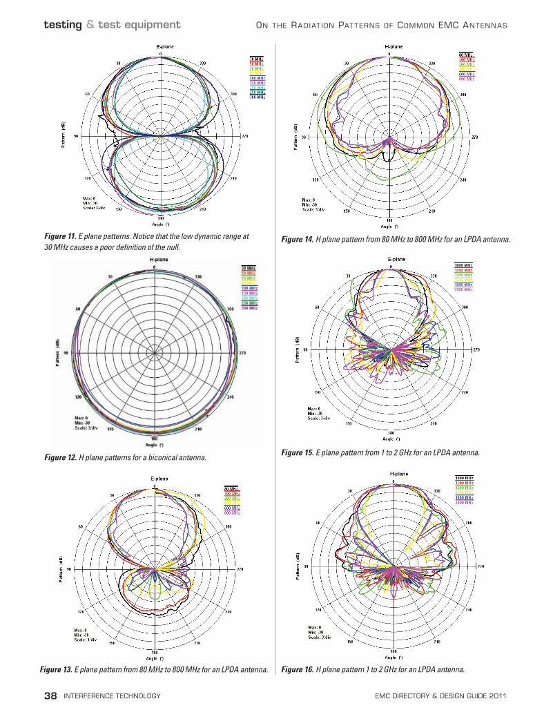
200 MHz to 2 GHz. Their patterns are very similar as long as their geometry has the same design parameters [1]. Figures 13 and 14 show the pattern for the log periodic antenna for frequen-cies below 1GHz. Notice that the E plane pattern has a null in the 90 and 270 degrees direction. This is similar to dipoles, which are the elements that make the array on a LPDA. Figures 15 and 16 show the patterns at different frequencies above 1GHz.
The HPBW of LPDA antennas is usually fairly flat. This is especially the case for the center of the frequency band that the antenna covers. From about 200 to 1500 MHz the antennas being measured exhibit an HPBW averaging 50 degrees for both planes.
HYBRid AntennASAlthough hybrid antennas are not par-
Figure 8. Results for the model in Figure 7. Notice that the radiation is deflected by the presence of the metallic top bench.
Figure 9. The test set up in the rectangular anechoic chamber.
Figure 10. The outdoor set up. A ferrite tile patch is place on the ground plane between the antennas to reduce the effects of the OATS on the measurement.
38 interference technology emc Directory & Design guiDe 2011
testing & test equipment On the Radiat iOn Pat teRns Of COmmOn emC antennas
Figure 11. E plane patterns. Notice that the low dynamic range at 30 MHz causes a poor definition of the null.
Figure 12. H plane patterns for a biconical antenna.
Figure 13. E plane pattern from 80 MHz to 800 MHz for an LPDA antenna.
Figure 15. E plane pattern from 1 to 2 GHz for an LPDA antenna.
Figure 14. H plane pattern from 80 MHz to 800 MHz for an LPDA antenna.
Figure 16. H plane pattern 1 to 2 GHz for an LPDA antenna.

ROdRiguez
interferencetechnology.com interference technology 39
testing & test equipment
Figure 17. E plane pattern from 30 to 900 MHz for a hybrid antenna.
Figure 18. H plane pattern from 30 to 900 MHz for a hybrid antenna.
Figure 19. E plane pattern from 2 to 6 GHz for a hybrid antenna.
Figure 20. H plane pattern from 2 to 6 GHz for a hybrid antenna.
degrees at the frequencies below 100 MHz. Once the log periodic section is active, the HPBW is fairly flat unless there are changes to the LPDA design parameters.
duAL Ridge HoRnSDual Ridge Horn Antennas (DRHA) are the antenna of choice for MIL STD [2]. This family of antennas have been the best described family in the literature. This is especially true regarding their radiation patterns. Starting with [6] there was a big issue with the upper frequency behavior of the patterns of Dual Ridge Horn Antennas. In [7-10] several improvements were done to the radiation patterns of these antennas to avoid nulls in the middle on the main beam. HPBW information for the three most common models of dual ridge horn antennas are shown in Figures 21 to 23. These are the models where the pattern performance has been improved as described in the references [8-10].
concLuSion The reader has been introduced to antenna pattern nomen-clature. The different concepts and parameters that describe patterns have been defined and illustrated. Finally pattern and HPBW information has been given for the most com-mon EMC antennas used.
AcKnoWLedgeMentSThe author would like to thank the antenna calibration lab at ETS-Lindgren in Cedar Park, Texas for their help in setting up the OATS for measuring the patterns below 400 MHz. The author also would like to thank the staff of the CTIA authorized test laboratory (CATL) at ETS-Lindgren for their help in measuring the patterns in two of their four anechoic chambers. Finally, the author thanks the marketing depart-ment at ETS-Lindgren for the pictures taken of the different set-ups needed for the measurement of the patterns.

40 interference technology emc Directory & Design guiDe 2011
testing & test equipment On the Radiat iOn Pat teRns Of COmmOn emC antennas
ReFeRenceS• [1] C. Balanis, Antenna Theory: Analysis and Design, 2nd ed., John
Wiley and Sons: New York, 1997.• [2] “Mil STD 461F Department of Defense Interface Standard: Re-
quirements for the Control of Electromagnetic Interference Charac-teristics of Subsystems and Equipment,” U.S. Department of Defense, December 2007.
• [3] CISPR 25, “Radio Disturbance Characteristics for the Protection of Receivers used on Board Vehicles, Boats, and on Devices- Limits and Methods of Measurement,” 2nd ed., IEC Geneva, Switzerland 2002.
• [4] “SAE Surface Vehicle Electromagnetic Compatibility (EMC) Stan-dards Manual,” Society of Automotive Engineers, Warrendale, PA 1999.
• [5] CISPR 16-1-4, “Specification for Radio Disturbance and Immunity Measurement Apparatus and Methods Part 1-4 Radio Disturbance and Immunity Measuring Apparatus – Antennas and Test Sites for Radiated Disturbance Measurements,” 3rd ed., IEC Geneva, Swit-zerland 2010.
• [6] C. Bruns, P. Leuchtmann, and R. Vahldieck, “Analysis of a 1-18 GHz Broadband Double-Ridge Antenna,” IEEE Transactions of Elec-tromagnetic Compatibility, Vol. 45 No. 1 February 2003: 55-60. Print.
• [7] V. Rodriguez, “New Broadband EMC Double-Ridge Guide Horn Antenna,” RF Design, May 2004: 44-50. Print.
• [8] V. Rodriguez, “A New Broadband Double Ridge Guide Horn with Improved Radiation Pattern for Electromagnetic Compatibility Testing,” 16th International Zurich Symposium on Electromagnetic compatibility, Zurich, Switzerland, February 2005.
• [9] V. Rodriguez, “Improvements to Broadband Dual Ridge Waveguide Horn Antennas,” 2009 IEEE International Symposium on Antennas and Propagation and USNC/URSI National Radio Science Meeting, Charleston, SC, June 2009.
• [10] V. Rodriguez, “Recent Improvements to Dual Ridge Horn Anten-nas: The 200 MHz to 2 GHz and 18 GHz to 40 GHz Models,” 2009 IEEE International Symposium on EMC, Austin, TX, Aug. 2009.
Vicente Rodriguez attended Ole Miss, in Oxford Miss., where he ob-tained his B.S.E.E. M.S. and Ph.D. degrees in 1994, 96 and 99 respectively. In June 2000, after a short period as visiting professor at the department of Electrical Engineering and Computer Science at Texas A&M University-Kingsville, Dr. Rodriguez joined EMC Test Systems (now ETS-Lindgren) as an RF and Electromagnetics engineer. In September 2004, Dr. Rodriguez took over the position of Senior Principal Antenna Design Engineer, placing him in charge of the development of new antennas for different applications and on improving the existing antenna line. In 2006, Dr. Rodriguez became Acting Antenna Product Manager placing him in charge of the development, marketing and maintenance of the antenna product line. During the fall of 2010, Dr. Rodriguez became the official Antenna Product Manager.
During his time at ETS-Lindgren, he has been involved in the RF an-echoic design of several chambers, including rectangular and taper antenna pattern measurement chambers, some of which operate from 100 MHz to 40 GHz. He was also the principal RF engineer for the anechoic chamber at the Brazilian Institute for Space Research (INPE), the largest chamber in Latin America and the only fully automotive EMC and Satellite test-ing chamber. Among the antennas developed by Dr. Rodriguez are new broadband double and quad-ridged guide horns with single lobe pattern and high field generator horns for the automotive and defense industry, as well as omnidirectional antennas for field surveying. He can be reached at [email protected] n
Figure 21. HPBW for both principal planes for an improved designed of the 200 MHz to 2 GHz DRHA.
Figure 22. HPBW for both principal planes for the improved design of the 1 to 18 GHz DRHA.
Figure 23. HPBW for both principal planes for an improved design of the 18 to 40 GHz DRHA.