on the stability of a geodetic no-net-rotation frame and
TRANSCRIPT

On the stability of a geodetic no-net-rotation frame and its implication
for the International Terrestrial Reference Frame
Corne Kreemer,1 David A. Lavallee,2 Geoffrey Blewitt,1,3 and William E. Holt4
Received 1 June 2006; revised 15 July 2006; accepted 31 July 2006; published 7 September 2006.
[1] One of the important implications of a no-net-rotation(NNR) model of the Earth’s horizontal surface velocity is thatit is used as a constraint in the definition of the InternationalTerrestrial Reference Frame (ITRF).Wepresent here ourmostrecent estimates of an NNRmodel (GSRM-NNR-2) that usesover 5700 geodetic station velocities. We test the sensitivityof our model by varying data input and model assumptions.The difference between our various models is maximally0.6mmyr�1, but can be larger if we use only a geographicallylimited core velocity data set, or if a significant bias in frameorigin translation rate exists. Although plate boundary zonesshould not be considered as being part of rigid plates(Kreemer and Holt, 2001), the details of the velocity fieldwithin the plate boundaries have an insignificant effect on theNNR frame. The difference between the variousNNRmodelsthat we test is small compared to the difference between ourNNRmodels and ITRF2000,which can be up to 3.1mmyr�1.We conclude that the ITRF2000 does not satisfy the NNRcondition when considering an NNR model that is based onthe actual present-day velocity of the entire Earth’s surface,instead of NNR-NUVEL-1A. Citation: Kreemer, C., D. A.
Lavallee, G. Blewitt, and W. E. Holt (2006), On the stability of a
geodetic no-net-rotation frame and its implication for the
International Terrestrial Reference Frame, Geophys. Res. Lett.,
33, L17306, doi:10.1029/2006GL027058.
1. Introduction
[2] By convention [e.g., McCarthy and Petit, 2004], thetime evolution of the International Terrestrial ReferenceFrame (ITRF) is defined such that there should be no-net-rotation (NNR) of the frame with respect to the Earth’slithosphere. In practice the ITRF2000 orientation timeevolution was defined by minimizing its 3 rotation rateswith respect to the NNR-NUVEL-1A plate motion modelusing the horizontal velocities of a polyhedron of core ITRFsites [Altamimi et al., 2002, 2003]. The NNR condition iskinematically defined by setting the following integral overthe Earth’s surface to be zero [Solomon and Sleep, 1974]:
IZsurface
v� r½ �dA ¼ 0 ð1Þ
where v is the horizontal velocity at surface position r, anddA is an infinitesimal element of surface area at r. Inpractice we evaluate (1) over finite areas (0.6� by 0.5�).From (1) one can derive an NNR model from any platemotion model. NNR-NUVEL-1A [Argus and Gordon,1991] is one such model that satisfies the NNR condition,but is based on a surface velocity model of the Earth(i.e., NUVEL-1A [DeMets et al., 1994]) that incorrectlydescribes the present-day velocity of part of the Earth’ssurface [Kreemer and Holt, 2001]. These shortcomings ofNNR-NUVEL1A result from the Earth’s surface beingsolely parameterized by rigid spherical caps (therebyignoring the deforming plate boundary zones, which canbe very wide), and from errors in NUVEL-1A’s estimate ofpresent-day relative plate motions [e.g., Sella et al., 2002;Kreemer et al., 2003].[3] The alignment of ITRF2000 to NNR-NUVEL1A
does not guarantee that the ITRF2000 frame satisfies anNNR condition that is internally consistent with the surfacevelocity field implied by the ITRF2000 station velocities. Amore accurate NNR condition is one based on an NNRmodel that is derived from our best knowledge of thepresent-day horizontal surface velocity field everywhereon the Earth’s surface. Such models are starting to emergethrough a combination of geodetic velocity data and inter-polation and/or finite element techniques [Kreemer et al.,2000; Drewes and Angermann, 2001]. One such model isthe Global Strain Rate Map (GSRM) [Kreemer et al., 2003],which is parameterized as a set of rigid spherical caps withdeformable plate boundary zones between them. GSRM ismainly based on geodetic velocity estimates and is definedin a self-consistent manner by the rigid body rotations of 25spherical caps and a velocity gradient tensor field for theplate boundary zones [Kreemer et al., 2003]. When usingthe GSRM model, the NNR model is implicitly derivedfrom a plate-fixed kinematic model. This study aims toquantify the stability and sensitivity of the latest GSRM-NNR frame in terms of modeling assumptions and datainput. These tests are necessary to verify the stability of theGSRM-NNR model and to assess its difference with ITRF.This, in turn, would be important if a model like GSRM-NNR-2 were to be adopted as the NNR model for thealignment of future generations of ITRF.
2. Kinematic Model
[4] We use a core velocity solution onto which availablepublished velocities are transformed. The core solutionconsists of a velocity field estimated from weekly globaland regional GPS solutions from the International GNSSService (IGS) analysis for 372 sites between 1996.75 and2005.5. Velocity solutions are computed for four IGS
GEOPHYSICAL RESEARCH LETTERS, VOL. 33, L17306, doi:10.1029/2006GL027058, 2006ClickHere
for
FullArticle
1Nevada Bureau of Mines and Geology, and Seismological Laboratory,University of Nevada, Reno, Nevada, USA.
2School of Civil Engineering and Geosciences, Newcastle University,Newcastle upon Tyne, UK.
3Also at School of Civil Engineering and Geosciences, NewcastleUniversity, Newcastle upon Tyne, UK.
4Department of Geosciences, State University of New York, StonyBrook, New York, USA.
Copyright 2006 by the American Geophysical Union.0094-8276/06/2006GL027058$05.00
L17306 1 of 5
regional associate analysis centers (Australia, Europe, Southand North America) and are attached to a central solutioncomputed from re-processed results from the IGS analysiscenter at Scripps Institute of Oceanography. Using a free-network approach [Davies and Blewitt, 2000] all stationswith a minimum of 104 observations over a minimum of2.5-year data-span are fitted to a constant linear stationmotion model. The minimum data requirements are intro-duced so that velocity estimates are reliable in the presenceof seasonal signals [Blewitt and Lavallee, 2002]. Theresulting free network solution is aligned to ITRF2000 byestimating a 14 parameter Helmert transformation.[5] Station velocity solutions from 93 published (or
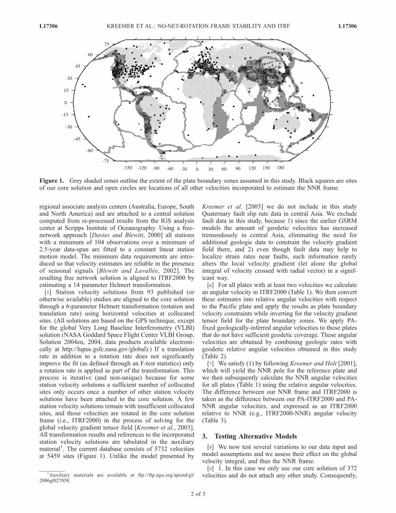
otherwise available) studies are aligned to the core solutionthrough a 6-parameter Helmert transformation (rotation andtranslation rate) using horizontal velocities at collocatedsites. (All solutions are based on the GPS technique, exceptfor the global Very Long Baseline Interferometry (VLBI)solution (NASA Goddard Space Flight Center VLBI Group,Solution 2004en, 2004, data products available electroni-cally at http://lupus.gsfc.nasa.gov/global).) If a translationrate in addition to a rotation rate does not significantlyimprove the fit (as defined through an F-test statistics) onlya rotation rate is applied as part of the transformation. Thisprocess is iterative (and non-unique) because for somestation velocity solutions a sufficient number of collocatedsites only occurs once a number of other station velocitysolutions have been attached to the core solution. A fewstation velocity solutions remain with insufficient collocatedsites, and those velocities are rotated in the core solutionframe (i.e., ITRF2000) in the process of solving for theglobal velocity gradient tensor field [Kreemer et al., 2003].All transformation results and references to the incorporatedstation velocity solutions are tabulated in the auxiliarymaterial1. The current database consists of 5732 velocitiesat 5459 sites (Figure 1). Unlike the model presented by
Kreemer et al. [2003] we do not include in this studyQuaternary fault slip rate data in central Asia. We excludefault data in this study, because 1) since the earlier GSRMmodels the amount of geodetic velocities has increasedtremendously in central Asia, eliminating the need foradditional geologic data to constrain the velocity gradientfield there, and 2) even though fault data may help tolocalize strain rates near faults, such information rarelyalters the local velocity gradient (let alone the globalintegral of velocity crossed with radial vector) in a signif-icant way.[6] For all plates with at least two velocities we calculate
an angular velocity in ITRF2000 (Table 1). We then convertthese estimates into relative angular velocities with respectto the Pacific plate and apply the results as plate boundaryvelocity constraints while inverting for the velocity gradienttensor field for the plate boundary zones. We apply PA-fixed geologically-inferred angular velocities to those platesthat do not have sufficient geodetic coverage. These angularvelocities are obtained by combining geologic rates withgeodetic relative angular velocities obtained in this study(Table 2).[7] We satisfy (1) by following Kreemer and Holt [2001],
which will yield the NNR pole for the reference plate andwe then subsequently calculate the NNR angular velocitiesfor all plates (Table 1) using the relative angular velocities.The difference between our NNR frame and ITRF2000 istaken as the difference between our PA-ITRF2000 and PA-NNR angular velocities, and expressed as an ITRF2000relative to NNR (e.g., ITRF2000-NNR) angular velocity(Table 3).
3. Testing Alternative Models
[8] We now test several variations to our data input andmodel assumptions and we assess their effect on the globalvelocity integral, and thus the NNR frame.[9] 1. In this case we only use our core solution of 372
velocities and do not attach any other study. Consequently,
Figure 1. Grey shaded zones outline the extent of the plate boundary zones assumed in this study. Black squares are sitesof our core solution and open circles are locations of all other velocities incorporated to estimate the NNR frame.
1Auxiliary materials are available at ftp://ftp.agu.org/apend/gl/2006gl027058.
L17306 KREEMER ET AL.: NO-NET-ROTATION FRAME STABILITY AND ITRF L17306
2 of 5

for many plate boundary zones the site coverage is verysmall, and for several plates the geographic coverage ismore limited (e.g., Pacific, Nazca, Somalia) than our pre-ferred solution (Figure 1) leading to some different plateangular velocities.[10] 2. Instead of our own core velocity solution we use
another global solution (Z. Altamimi, personal communica-tion, 2006) to which to attach the published station velocitysolutions. Because Altamimi’s solution already has theDORIS and VLBI techniques included, we do not attachvelocities from the VLBI technique, as we would otherwisedo (see Table S1).[11] 3. Kreemer and Holt [2001] argued that plate bound-
ary zones, which deform, should not be modeled as beingpart of adjacent rigid plates, and they showed that such afalse assumption significantly changed their NNR model.Most plate boundaries are now fairly well covered withgeodetic velocity measurements (Figure 1), but any signif-icant future change to the global velocity field couldarguably come from a refined knowledge of the velocityfield there. As an extreme test we calculate the velocitygradient tensor field without using any data within the plateboundary zones. The velocity field within those zones istherefore simply the velocity gradient field that satisfies theplate velocity constraints imposed on the rigid adjacentplates and blocks.[12] 4. Our estimate of the angular velocities of some
plates (e.g., North America (NA), Eurasia) could changesignificantly once the effects of glacial isostatic adjustments(GIA) have been properly accounted for. In an ongoingstudy of NA plate motion the GIA signal has been removedfrom the observed velocities in order to obtain an improved
secular estimate [Blewitt et al., 2005]. As a test we use thatestimate (wx = 0.0183, wy = �0.1851, wz = �0.0241),converted to a PA-fixed frame, as a velocity boundaryconstraint instead of that listed in Table 1.[13] 5. Some plates’ geodetic motions are currently
undetermined because there are insufficient geodetic veloc-ities to calculate an angular velocity. Examples are the Juande Fuca (JF) and Cocos (CO) plates. Geologic rates havebeen estimated for these plates (Table 2), but it is possiblethat these are significantly different than the actual present-day rates. For example, such a discrepancy has been foundfor the Nazca plate [Angermann et al., 1999; Norabuena etal., 1999], which geodetic rotation rate relative to SouthAmerica is 84% of that of NUVEL-1A [Kreemer et al.,2003]. As a test we impose an angular velocity constraintfor the unconstrained plates (JF, CO, Rivera, Scotia, Cap-
Table 1. Plate Angular Velocitiesa
Plate Nb
ITRF2000 No-Net-Rotation
wx, � Myr�1 wy, � Myr�1 wz, � Myr�1 r(x, y) r(x, z) r(y, z) wx wy wz
Amur 38 �0.063 ± 0.006 �0.118 ± 0.009 0.248 ± 0.012 �0.88 �0.89 0.95 �0.055 �0.130 0.266Anatolia 3 0.907 ± 0.180 0.460 ± 0.122 0.891 ± 0.170 1.00 1.00 1.00 0.915 0.448 0.910Antarctica 12 �0.065 ± 0.001 �0.087 ± 0.001 0.186 ± 0.003 0.14 �0.18 0.38 �0.057 �0.099 0.205Arabia 9 0.325 ± 0.014 �0.001 ± 0.016 0.417 ± 0.011 0.98 0.96 0.96 0.334 �0.013 0.436Australia 36 0.414 ± 0.002 0.314 ± 0.001 0.328 ± 0.001 �0.71 0.71 �0.60 0.422 0.302 0.347Capricornc – – – – – – – 0.422 0.318 0.409Caribbean 5 �0.016 ± 0.006 �0.207 ± 0.015 0.161 ± 0.006 �0.93 0.74 �0.78 �0.008 �0.219 0.180Carolinec – – – – – – – 0.462 �0.132 �0.747Cocosc – – – – – – – �0.617 �1.211 0.648Eurasia 157 �0.030 ± 0.001 �0.137 ± 4e-4 0.208 ± 0.001 0.29 0.93 0.33 �0.022 �0.149 0.226India 5 0.298 ± 0.011 �0.028 ± 0.049 0.389 ± 0.015 0.95 0.88 0.92 0.307 �0.041 0.408J. de Fucac – – – – – – – 0.577 0.890 �0.859Nazca 5 �0.076 ± 0.004 �0.408 ± 0.012 0.436 ± 0.006 0.14 0.08 0.68 �0.068 �0.420 0.454N. America 104 0.022 ± 4e-4 �0.193 ± 0.002 �0.017 ± 0.002 �0.18 0.16 �0.76 0.030 �0.205 0.002Nubia 11 0.032 ± 0.003 �0.159 ± 0.001 0.200 ± 0.001 �0.07 0.30 �0.08 0.040 �0.172 0.218Okhotsk 6 0.151 ± 0.161 �0.228 ± 0.064 �0.231 ± 0.259 �0.99 �1.00 1.00 0.159 �0.241 �0.213Pacific 30 �0.098 ± 0.002 0.281 ± 0.002 �0.608 ± 0.001 0.25 0.08 �0.06 �0.090 0.269 �0.589Philip. Sea 3 0.483 ± 0.206 �0.216 ± 0.225 �0.652 ± 0.125 �0.98 �0.99 0.99 0.491 �0.229 �0.634Riverac – – – – – – – �1.232 �4.054 1.582Scotiac 1 – – – – – – �0.011 �0.148 �0.008Somalia 7 �0.010 ± 0.008 �0.199 ± 0.008 0.253 ± 0.003 0.91 0.11 0.10 �0.002 �0.211 0.272S. America 37 �0.055 ± 0.002 �0.085 ± 0.002 �0.047 ± 0.002 �0.77 �0.69 0.76 �0.047 �0.098 �0.029S. China 24 �0.078 ± 0.012 �0.107 ± 0.028 0.293 ± 0.016 �0.98 �0.97 0.98 �0.070 �0.120 0.312Sunda 21 �0.002 ± 0.006 �0.265 ± 0.021 0.252 ± 0.004 �0.92 �0.46 0.49 0.006 �0.277 0.270Tarim 5 �0.003 ± 0.010 �0.528 ± 0.116 �0.110 ± 0.096 0.90 0.90 1.00 0.005 �0.540 �0.091
ar(x, y), r(x, z), and r(y, z) are the correlation coefficient between x and y, x and z, and y and z directions, respectively.bNumber of velocities per plate.cThese plates have insufficient velocities to determine their angular velocity geodetically. Their no-net-rotation angular velocity is inferred from
including published geologic rates. One could infer their ITRF2000 angular velocities by subtracting our ITRF2000-NNR angular velocity (Table 3).
Table 2. Angular Velocities of Plates That Are Not Constrained
by Geodetic Velocitiesa
PlateLat.,�N
Lon.,�E
_w,�Myr�1 Study
Capricorn 62.8 5.5 1.12 DeMets et al. [2005]Caroline �13.0 �36.0 0.70 Weissel and Anderson [1978]Cocos 38.2 �109.6 2.00 DeMets [2001]J. de Fuca �16.5 43.0 0.95 Wilson [1993]Rivera 25.9 �104.8 4.97 DeMets and Wilson [1997]Scotia 53.9 �79.3 0.72 Thomas et al. [2003]
aAngular velocities are with respect to the Pacific plate. If study providedan angular velocity with respect to a plate other than Pacific, we have addedto the published values the appropriate relative angular velocity determinedgeodetically in this study.
L17306 KREEMER ET AL.: NO-NET-ROTATION FRAME STABILITY AND ITRF L17306
3 of 5
ricorn, Caroline) that is also at 84% of the rate presented inthe literature.[14] 6. Any real net translation rate of the crust relative to
the Earth’s center of mass that is not due to tectonicdeformation is likely to be small, <1mm yr�1 [Trupin etal., 1992; Argus et al., 1999; Greff-Lefftz, 2000]. Geodesyhas not yet reached the required precision to quantify anysuch translation rate; furthermore, defining the translationrate of the frame origin is confounded by orbit errors anddeficiencies in tracking network sampling [Argus et al.,1999]. Altamimi et al. [2002] found that SLR translationrates can be �1.0 mm yr�1 (in Z-direction) and can be evenlarger for GPS. The ITRF origin rate definition is thereforeuncertain at this level.[15] To test the affect on the NNR frame, we translate our
velocity solution with 1.7 mm yr�1 towards 36�N and111�E, which changes the horizontal velocity field, beforewe calculate plate angular rotations and determine the NNRframe. This translation rate is equal to that inferred on thebasis of the comparison between vertical VLBI velocitiesand GIA predictions [Argus, 1996]. Although this transla-tion rate does not necessarily reflect any existing translationrate bias in ITRF2000, it serves as an illustration. It shouldbe noted that the direction of the translation rate is impor-tant, because different directions will impact the plateangular velocities differently, and therefore the impact onthe NNR frame will vary with the direction of any transla-tion rate.
4. Discussion and Conclusions
[16] We find that the inter-model differences betweenmost of our different NNR model realizations are relativelysmall. The difference between the NNR models in Table 3leads to a maximum velocity (at 90� away from the Eulerpole corresponding to the relative angular velocities: umax)that is 1.8 mm yr�1 for Case 1, 1.8 mm yr�1 for Case 6, and0.6 mm yr�1 for the other cases. It is anticipated that thedifference between Case 1 and our preferred model willdiminish in the future as the spatial coverage of the IGSnetwork (and hence our core solution) increases. Theincorporation of a large translation rate of 1.7 mm yr�1
results in the largest difference in NNR frame compared toour preferred model. The fact that the difference betweenthe ITRF2000-NNR angular velocities for Case 6 and ourpreferred model (Table 3) is minimal is because the addi-
tional translation rate in Case 6 equally affects the ITRF andNNR velocities. We conclude that the assessment of apossible frame translation rate bias should be a subject forcontinuing research, because it not only affects the origindefinition but, if the bias is significant, the NNR frame aswell. Also, future work needs to assess the sensitivity of thedirection of the translation rate bias on the NNR frame.[17] Our results indicate that if we use the SNARF
angular velocity for North America instead of the one basedon velocities that are not adjusted for the effects of GIA, ourNNR frame is not significantly affected. However, it is notcertain whether this conclusion still stands if SNARF-likeangular velocities would be available, and used, for otherplates, such as Eurasia.[18] Kreemer and Holt [2001] showed that it is important
to not model the plate boundary zones as if they are part ofthe rigid adjacent plates. That conclusion still stands, but thesmall difference between Case 3 and our preferred modelindicates that the NNR frame is not very sensitive to the finedetails of the velocity field within the plate boundary zones(the difference in models relates to a maximum differentialvelocity of 0.3 mm yr�1). When we set the rates for theunconstrained plates to be 84% of the most recent estimatedgeologic rates (i.e., Case 5) the difference in NNR model isrelatively small. In our preferred model the summed arealvelocity of the six unconstrained plates is 2.6% of the globalintegral, and evidently changing those velocities has nosignificant effect on the outcome of (1). However, furthertests show that if we change those plate rates to being 50%of published geologic rates the impact on NNR is signifi-cant. Such a drastic difference between true and inferredgeologic rates is, on the other hand, probably unrealistic.[19] The difference between our various NNR model
cases is small compared to the difference between any ofour NNR frames and ITRF2000. For most cases thedifference amounts to a rotation whose associated Eulerpole can generally be found in western Canada. The relatedvelocity difference can be up to 2.6–3.1 mm yr�1 (vmax:Table 3) in parts of Eurasia, South America, Africa and thePacific (not considering Case 1). This is a large differenceconsidering the uncertainty in the NNR frame and thestandard velocity error for most (continuous) stations. Thedifference is slightly larger than the 2.3 mm yr�1 thatAltamimi et al. [2003] estimated to be the maximumvelocity related to the difference between ITRF2000 andthe NNR model of Kreemer and Holt [2001] (as estimatedusing the velocities at 50 ITRF core sites). We conclude thatITRF2000 does not satisfy the NNR constraint if the NNRmodel is based on the actual present-day velocity of theentire Earth’s surface.[20] For matters of consistency it would be acceptable for
future ITRF generations to continue having the framealigned to the NNR-NUVEL1A model, even if that entailsthat ITRF does not satisfy a true NNR condition based onpresent-day surface kinematics. However, one of the mainproblems with the current alignment procedure is that it islimited to using only sites far away from plate boundaries.The use of the GSRM-NNR-2 model instead of NNR-NUVEL1A would alleviate that restriction and would si-multaneously ensure a proper NNR condition for ITRF. Weshow here that given a small frame translation rate bias andsufficient global coverage, GSRM-NNR-2 has sub mm yr�1
Table 3. ITRF2000-NNR Angular Velocitiesa
wx wy wz vmax umax
Pref. Model 0.00811 �0.01222 0.01860 2.6 –Case 1 0.01641 �0.01860 0.02300 4.3 1.8Case 2 0.01124 �0.01087 0.01744 2.6 0.6Case 3 0.00759 �0.01485 0.01950 2.9 0.3Case 4 0.00854 �0.01272 0.01868 2.7 0.1Case 5 0.00960 �0.01185 0.02367 3.1 0.6Case 6 0.00896 �0.01239 0.01982 2.8 1.8
aDifference between our NNR model and ITRF2000 expressed as anangular velocity (� Myr�1) and vmax (mm yr�1) which is the horizontalvelocity 90� away from corresponding Euler pole. Different cases arediscussed in text. umax is the maximum velocity difference corresponding tothe relative angular velocity between our preferred NNR model and thedifferent cases.
L17306 KREEMER ET AL.: NO-NET-ROTATION FRAME STABILITY AND ITRF L17306
4 of 5
stability. Whether it is worth making the change from usingNNR- NUVEL1A to a model like GSRM-NNR (and suchchange may also require significant change in Earth Orien-tation Parameters) should remain subject to ongoing re-search and discussions.
[21] Acknowledgments. We thank the IGS community for both GPSdata and SINEX products, in particular we thank the IGS analysis centers;Australian Surveying and Land Information Group (AUSLIG), EuropeanCoordinating Regional Network Analysis Center (EUREF), NaturalResources Canada (NRCAN), Scripps Institute of Oceanography (SIO)and the IGS regional network for South America (SIRGAS) for providingweekly SINEX. We thank Z. Altamimi for making his most recent velocitydata set available to us. This research has made use of NASA GoddardSpace Flight Center’s VLBI terrestrial reference frame solution number2004en. We thank the following individuals for kindly providing us with(supplemental) geodetic velocities from their studies: T. Arnadottir,A. Avallone, J. Beavan, B. Brooks, E. Calais, C. DeMets, R. Fernandez,J. Freymueller, B. Hager, W. Hammond, T. Kato, J. Klotz, P. LaFemina,S. Mazzotti, S. McClusky, J.-M. Nocquet, J. Oldow, C. Reigber, T. Sagiya,R. Trenkamp (and INGEOMINAS), R. Smalley, R. Smith. A. Socquet,P. Tregoning, and A. van der Hoeven. We are grateful to the Jet PropulsionLaboratory for the GIPSY OASIS II software and precise GPS orbitproducts. This work has been conducted with support from NASA’s SolidEarth and Natural Hazards grant SENH-0225-0008 and a Royal SocietyUniversity Research Fellowship to DAL. This paper benefited from com-ments by Z. Altamimi and an anonymous reviewer.
ReferencesAltamimi, Z., P. Sillard, and C. Boucher (2002), ITRF2000: A new releaseof the International Terrestrial Reference Frame for earth science applica-tions, J. Geophys. Res., 107(B10), 2214, doi:10.1029/2001JB000561.
Altamimi, Z., P. Sillard, and C. Boucher (2003), The impact of a No-Net-Rotation Condition on ITRF2000, Geophys. Res. Lett., 30(2), 1064,doi:10.1029/2002GL016279.
Angermann, D., et al. (1999), Space-geodetic estimation of the Nazca-South America Euler vector, Earth Planet. Sci. Lett., 171, 329–334.
Argus, D. F. (1996), Postglacial rebound from VLBI geodesy: On establish-ing vertical reference, Geophys. Res. Lett., 23, 973–976.
Argus, D. F., and R. G. Gordon (1991), No-net-rotation model of currentplate velocities incorporating plate motion model NUVEL-1, Geophys.Res. Lett., 18, 2039–2042.
Argus, D. F., et al. (1999), Glacial isostatic adjustment observed using verylong baseline interferometry and satellite laser ranging geodesy, J. Geo-phys. Res., 104, 29,077–29,093.
Blewitt, G., and D. Lavallee (2002), Effect of annual signals on geodeticvelocity, J. Geophys. Res., 107(B7), 2145, doi:10.1029/2001JB000570.
Blewitt, G., et al. (2005), A stable North America reference frame(SNARF): First release, paper presented at UNAVCO-IRIS Joint Work-shop, Stevenson, Wash.
Davies, P., and G. Blewitt (2000), Methodology for global geodetic timeseries estimation: A new tool for geodynamics J, Geophys. Res., 105,11,083–11,100.
DeMets, C. (2001), A new estimate for present-day Cocos-Caribbean platemotion: Implications for slip along the Central American volcanic arc,Geophys. Res. Lett., 28, 4043–4046.
DeMets, C., and D. Wilson (1997), Relative motions of the Pacific, Rivera,North American, and Cocos plates since 0.78 Ma, J. Geophys. Res., 102,2789–2806.
DeMets, C., et al. (1994), Effect of recent revisions to the geomagneticreversal time-scale on estimates of current plate motions, Geophys. Res.Lett., 21, 2191–2194.
DeMets, C., et al. (2005), Motion between the Indian, Capricorn and So-malian plates since 20 Ma: Implications for the timing and magnitude ofdistributed lithospheric deformation in the equatorial Indian ocean, Geo-phys. J. Int., 161, 445–468.
Drewes, H., and D. Angermann (2001), The actual plate kinematic andcrustal deformation model 2000 (APKIM2000) as a geodetic referencesystem, paper presented at IAG Scientific Assembly, Int. Assoc. ofGeod., Budapest.
Greff-Lefftz, M. (2000), Secular variation of the geocenter, J. Geophys.Res., 105, 25,685–625,692.
Kreemer, C., and W. E. Holt (2001), A no-net-rotation model of present-daysurface motions, Geophys. Res. Lett., 28, 4407–4410.
Kreemer, C., et al. (2000), On the determination of a global strain ratemodel, Earth Planets Space, 52, 765–770.
Kreemer, C., et al. (2003), An integrated global model of present-dayplate motions and plate boundary deformation, Geophys. J. Int., 154,8–34.
McCarthy, D. M., and G. Petit (2004), IERS Conventions, 2003, IERS Tech.Note 32, 127 pp., Verlag des Bundesamts fur Kartogr. und Geod., Frank-furt, Germany.
Norabuena, E. O., et al. (1999), Decelerating Nazca-South America andNazca-Pacific plate motions, Geophys. Res. Lett., 26, 3405–3408.
Sella, G. F., T. H. Dixon, and A. Mao (2002), REVEL: A model for Recentplate velocities from space geodesy, J. Geophys. Res., 107(B4), 2081,doi:10.1029/2000JB000033.
Solomon, S. C., and N. H. Sleep (1974), Some physical models for absoluteplate motions, J. Geophys. Res., 79, 2557–2567.
Thomas, C., et al. (2003), Motion of the Scotia Sea plates, Geophys. J. Int.,155, 789–804.
Trupin, A. S., et al. (1992), Effect of melting glaciers on the Earthsrotation and gravitational field—1965–1984, Geophys. J. Int., 108,1–15.
Weissel, J. K., and R. N. Anderson (1978), Is there a caroline plate?, EarthPlanet. Sci. Lett., 41, 142–158.
Wilson, D. S. (1993), Confidence intervals for motion and deformation ofthe Juan de Fuca plate, J. Geophys. Res., 98, 16,053–16,071.
�����������������������G. Blewitt and C. Kreemer, Nevada Bureau of Mines and Geology, and
Seismological Laboratory, University of Nevada, Reno, NV 89557, USA.([email protected])W. E. Holt, Department of Geosciences, State University of New York,
Stony Brook, NY 11790, USA.D. A. Lavallee, School of Civil Engineering and Geosciences, Newcastle
University, Newcastle upon Tyne, NE1 7RU, UK.
L17306 KREEMER ET AL.: NO-NET-ROTATION FRAME STABILITY AND ITRF L17306
5 of 5