on the take-off of airborne wind energy systems based · pdf fileon the take-off of airborne...
TRANSCRIPT

On the Take-off of Airborne Wind Energy SystemsBased on Rigid Wings
L. Fagiano and S. Schnez∗
AbstractThe problem of launching a tethered aircraft to be used forairborne wind energy generation is investigated. Exploitingwell-assessed physical principles, an analysis of three dif-ferent take-off approaches is carried out. The approachesare then compared on the basis of quantitative and quali-tative criteria introduced to assess their technical and eco-nomic viability. Finally, a deeper study of the concept that isdeemed the most viable one, i.e. a linear take-off maneuvercombined with on-board propellers, is performed by meansof numerical simulations. The latter are used to refine theinitial analysis in terms of power required for take-off, andfurther confirm the viability of the approach.
1 IntroductionThe term airborne wind energy (AWE) refers to a class ofwind power generators that exploit tethered aircrafts to con-vert wind energy into electricity [4, 19]. The benefits ofAWE systems, compared to traditional wind turbines, areessentially two: lower construction and installation costsand the possibility to reach higher altitudes, where fasterand steadier winds blow. According to the current estimatesthe combination of these two benefits should render AWEsystems competitive with the established energy sources,including fossil fuels [20], in terms of both cost of energyand land occupation. The first papers and patents concernedwith AWE appeared in the late 1970s (see e.g. [31, 29]),yet only in recent years a significant and growing researcheffort has been undertaken by both small companies anduniversities to develop such concepts via theoretical, nu-merical and experimental methods [4]. AWE is still in itsinfancy and no commercial system exists; however, thanksto the continuous progresses that are being achieved, a rel-atively well-established set of few different approaches hasemerged, while other, less promising ideas have been aban-doned.
Today, AWE systems can be classified by the way thelift force that keeps the aircraft airborne is generated – ei-ther aerodynamic lift [24, 33, 36, 9, 34, 28], or aerostaticlift [37] – and by the placement of the electrical generators- either on-board of the aircraft [28, 37] or on the ground
∗This is the pre-print of a paper submitted for possible publicationto the Elsevier journal Energy. The authors are with ABB SwitzerlandLtd., Corporate Research, 5405 Baden-Dättwil - Switzerland. E-mail ad-dresses: { lorenzo.fagiano | stephan.schnez}@ch.abb.com. Both authorscontributed equally to this publication.
[24, 33, 9, 36, 34]. Among the systems that exploit aerody-namic lift and ground-level generators, a further distinctioncan be made between concepts that rely on rigid wings [34],similar to gliders, and concepts that employ flexible wings,like power kites [24, 33, 36, 9]. Small-scale prototypes(10-50 kW of rated power) of all of the mentioned con-cepts have been realized and successfully tested to demon-strate their power generation functionalities. Moreover, sci-entific contributions concerned with several different tech-nical aspects, primarily aerodynamics [11, 12, 10, 16, 27]and controls [26, 13, 7, 15, 22, 17, 23, 39, 14, 40] but alsoresource assessment [6, 5], economics [20, 41], prototypedesign [18] and power conversion [35], have recently ap-peared, gradually improving and expanding our understand-ing of such systems.
Despite the steady and promising development of thefield, the complexity and multidisciplinary nature of AWEsystems are such that several relevant aspects still need tobe addressed in order to ultimately prove the technical andeconomic feasibility of the idea. One of such aspects is thetake-off of the aircraft, particularly for concepts that em-ploy rigid wings and ground-level generation. In fact, whilesystems with on-board generation [28, 37], as well as kite-based systems with ground generation [24] are able to take-off autonomously from a quite compact ground area, thesame functionality for AWE systems with rigid wings andground-level generators has not been achieved yet. Thereis evidence of autonomous take-off of this class of gener-ators [1]; however by using a winch launch that requires asignificant space in all directions in order to adapt to thewind conditions during take-off. As a consequence, one ofthe main advantages of AWE systems, i.e. the possibility ofbeing installed in a large variety of locations at low costs,might be lost due to the need of a large area of land suit-able for the take-off. So far, this issue has been addressedonly to a limited extent within the scientific community.In Ref. [38], a rotational take-off is studied and simulated;however the focus is on the control and optimization aspectsof this approach, rather than on its economic viability andthe comparison with other possible methods. In Ref. [8], ananalysis of several approaches is first carried out, consid-ering different performance criteria, and three alternativesare deemed the most promising: buoyant systems, linearground acceleration plus on-board propeller, and rotationaltake-off. Then, the rotational take-off is examined in moredetail by means of numerical simulations.
In order to contribute to address this important problem,we present here an analysis of three candidate approaches torealize the take-off of a rigid tethered aircraft with ground-
1
arX
iv:1
510.
0670
1v1
[m
ath.
OC
] 2
2 O
ct 2
015

based generation. This is the concept which is also pursuedby the company Ampyx Power [1, 34]. More specifically,we compare a vertical lift approach with on-board vertical-axis propellers, a rotational take-off like the one consideredin Refs. [38, 8], and a linear take-off technique combinedwith on-board horizontal-axis propellers. The analysis isinstrumental to carry out a comparison among the consid-ered approaches, based on a series of performance criteriathat we introduce in order to quantify their viability. Theanalysis and the subsequent comparison represent the firstmain contribution that the present paper adds to the exist-ing scientific literature. Then, we study in more depth theconcept that is deemed the most viable one, i.e. the lineartake-off maneuver combined with on-board propellers. Inparticular, we derive a dynamical model of the system thatincludes realistic aerodynamic coefficients, as well as fric-tion and inertia, and we use it to refine the initial analysisin terms of power required for take-off. Since the system isunstable in open-loop, we also develop the feedback controlalgorithms required to stabilize the take-off maneuver andcarry out the numerical simulations.
The paper is organized as follows: section 2 providesmore details on the considered type of AWE system, whichare needed to formulate the problem that we address in arigorous way, and a brief description of the considered take-off approaches. The performance criteria are given in sec-tion 2, too. section 3 presents the analysis of the three take-off concepts using basic physical equations. The numericalsimulation study is reported in section 4. Final conclusionsare drawn in section 5 together with a discussion of futuredevelopments of this research.
2 Preliminaries and problem formu-lation
We first describe the system under consideration and intro-duce the physical equations that link the main lumped de-sign parameters to the generated mechanical power. Theseequations can be employed in a first-approximation dimen-sioning phase of the AWE generator and are used here tocompute one of our performance criteria. For the completedetails and derivation of the equations recalled in the fol-lowing, we refer to [29, 21, 19, 4].
2.1 Airborne wind energy systems based onrigid aircrafts and ground-level genera-tion
The considered AWE system is composed of a rigid aircraft,a ground unit (GU), and a tether connecting them, as de-picted in Figure 1. The aircraft is equipped with sensors,actuators and on-board intelligence to attain autonomousflight and realize the flight patterns required to generatepower, as well as with communication capabilities to ex-change information with the GU and possibly with othersystems and infrastructure nearby.
The GU consists of several subsystems, the main onesbeing a drum, around which the tether is coiled, an electric
Wind
Ground unit
X
Y
Z
ߴ
TractionRecovery
Transition
Transition Tether
Aircraft
Figure 1: Sketch of the considered AWE generator and itsworking principle during power production. In the trac-tion phase (red solid line) the aircraft is controlled to fol-low figure-of-eight patterns in crosswind conditions, andthe tether is reeled out under large load from the drum in-stalled in the GU. In the retraction phase (blue dash-dottedline), the aircraft is controlled to glide towards the groundstation, and the tether is reeled-in under small load. Twotransitions (green dashed lines) link the traction and retrac-tion phases. The aircraft position with respect to the incom-ing wind can be defined by the elevation angle ϑ and theazimuth angle ϕ.
machine (generator/motor), linked to the drum through amechanical transmission system, and the power electronicsystem to control the generator and to convert mechanicalpower into electrical one and vice-versa.
The described AWE system generates energy by meansof a cyclic operating principle composed essentially by fourphases: the power generation (or traction) phase, the retrac-tion phase, and two transition phases linking them, shownin Figure 1. During the traction phase, the on-board controlsystem steers the aircraft into figure-of-eight patterns undercrosswind conditions. The generated aerodynamic forcesexert a large traction load on the line, which is reeled-outfrom the drum. The electric machine exerts a torque onthe drum in order to achieve a desired reel-out speed andto produce power. In particular, an aircraft with effectivearea A, aerodynamic lift and drag coefficients Cl and Cd,respectively, flying at a relative elevation ϑ and azimuth ϕwith respect to a wind flow of speed W (see Figure 1), ex-erts a traction load T on the tether approximately equal to[29, 21, 19]:
T (t) ' 12ρA
Cl(t)3
Cd,eq(t)2(W (t) cos (ϕ(t)) cos (ϑ(t))− l(t)
)2 (1)
where t is the continuous time variable, ρ is the air density,Cd,eq
.= Cd(t) +
dl l(t)Cd,l4A is the equivalent drag coeffi-
cient (taking into account the drag of both the aircraft andthe line), l is the length of the line, assumed straight, dl its
2

diameter, Cd,l its drag coefficient, and l .= dldt is the tether
reeling speed. For l > 0, the line is reeled out from thedrum, hence effectively decreasing the apparent wind speedparallel to the tether direction, given by W cos (ϕ) cos (ϑ).The tether force T (t) multiplied with the reeling speed l(t)provides an estimate of the instantaneous mechanical powerPm(t) generated during the traction phase:
Pm(t) ' T (t) l(t). (2)
The maximum generated power is achieved when the reel-ing speed is equal to 1/3 of the absolute wind speed pro-
jected along the line direction, i.e. l =1
3W cos (ϕ) cos (ϑ),
and ideally with ϕ = ϑ = 0. In this case, the obtainedmechanical power is:
P ∗m(t) ' 2
27ρA .
Cl(t)3
Cd,eq(t)2W (t)3. (3)
For the sake of estimating the generated power, the massof the airborne components is irrelevant as a first approxi-mation, since the weight and apparent forces of the aircraftand of the line are significantly smaller than the force actingon the tether during the traction phase. On the other hand,this parameter clearly plays a crucial role when discussingtake-off approaches. In order to evaluate a given take-offtechnique on a quantitative basis, the total mass of the air-craft m has to be linked to the system’s capability in termsof force and power. Such a link is given by the so-calledwing loading wl, i.e. the ratio between m and the effectiveaerodynamic area A:
m = wlA. (4)
The total mass of the aircraft is the sum of m and of theadditional mass ∆mi required for the take-off capability.This will be discussed further in section 2.3.
2.2 Take-off approachesHere, we briefly describe the three take-off concepts underconsideration.
Vertical take-off with rotors. In this approach, the air-craft is equipped with vertical-axis propellers which pro-vide enough lift to take-off vertically. In the frameworkof ground-level generation, this approach is pursued by thecompany TwingTec [2]. In the AWE field, the companyMakani Power owned by Google [30, 28] employs this ap-proach for the take-off and landing their system with on-board power generation.
Rotational take-off. This is the only proposal for rigid-wing systems which has been studied in the literature withnumerical simulations in addition to static equations [8, 38].In this approach, the hull of the aircraft is initially attachedat the tip of a rotating arm. When the tangential speed ofthe arm is large enough, the aircraft takes off exploiting itsaerodynamic lift and the tether is gradually extended out ofthe rotating arm until a certain altitude is reached. Then, therotating arm is gradually stopped while the aircraft transi-tions into power-generating mode. The company EnerKite[3, 9] is implementing this concept for its AWE system.
Linear take-off with on-board propellers. In this ap-proach the aircraft is accelerated on a rectilinear path up totake-off speed by an external source of power, for exam-ple the winch itself or a linear motion system. Horizontal-axis on-board propellers are then employed to sustain theforward speed during the climb to the operational altitude.This approach was briefly analyzed and deemed promisingin Ref. [8], but without carrying out a deeper analysis bymeans of e.g. numerical simulations. The company AmpyxPower [1, 34] pursues a similar take-off concept as the onediscussed here.
In the remainder of this paper, we will use the sub-scripts 1, 2, 3 respectively for the vertical, rotational andlinear take-off approaches described above.
2.3 Performance criteria and problem formu-lation
A well-established metric to compare different electric powergeneration schemes on economic grounds is the levelizedcost of electricity (LCOE). In our case, additional compo-nents or land occupation required to implement the take-offapproach will increase upfront costs (and potentially main-tenance costs) and will lead to an increase in the LCOE ofthe AWE system, as compared to the same system withoutthe take-off functionality. Hence, when comparing differ-ent take-off approaches, their impact on the LCOE shouldbe assessed. However, the precise calculation of the LCOEis not feasible for new power generation concepts like AWEsystems.
Rather than the LCOE, we will therefore consider a se-ries of other quantitative and qualitative criteria which areeasier to evaluate based on the existing know-how of AWEgenerators, and which are related to the system’s cost, com-plexity and required land occupation. If a specific take-offapproach performs well according to these criteria, we canexpect that the impact on the LCOE of the AWE system willbe small.
The quantitative criteria are:
C1 The additional power installed on-board and on theground, relative to the peak mechanical power of thesystem, required to carry out the take-off procedure:
P g,i ' ηPg,i P ∗mP ob,i ' ηPob,i P ∗m
(5)
where P g and P ob stand for the peak ground and on-board power, respectively, and i = 1, 2, 3 refers tothe three considered take-off approaches. The higherthe values of ηPg,i, ηPob,i, the worse the approach.
C2 The additional on-board mass, relative to the aircraft’smass without the system required for the take-off:
∆mi ' ηm,i m. (6)
Although, as recalled in section 2.1, the mass doesnot impact the maximum power generation in a firstapproximation, it is an important parameter for the
3

controllability and maneuverability of the system andfor its capability to operate in a wide range of windconditions [22]. Again, the higher ηm,i, the worse theapproach.
C3 The ground area occupied by the take-off system, in-dicated with Ag,i:
Ag,i ' Ag,i + ηAg,i A, (7)
The higher Ag,i, ηAg,i, the worse the approach.
The qualitative criteria that we consider are:
C4 The complexity and cost of the apparatus that needsto be added to the system for the take-off functional-ity.
C5 The capability to take-off under most wind conditions(including no wind).
The problem we will address in the next section is tocarry out a comparison of the three considered approachesin light of criteria C1-C5. In particular, we will derive equa-tions that allow to compute the quantitative criteria C1-C3,and we will assess the criteria C4-C5 on the basis of theknowledge on AWE systems available in the literature andof our own hands-on experience.
3 Assessment of take-off concepts forrigid-wing AWE systems
In the following three sections 3.1, 3.2, and 3.3, we will in-troduce the relevant assumptions and derive the governingequations of the considered take-off approaches. Quantita-tive results and the related discussion will be presented insection 3.4.
3.1 Vertical take-off with rotorsAccording to the Actuator Disk Theory [25], the thrust througha disk with area Aprop is
T =1
2ρAprop
(v2out − v2in
), (8)
where the velocities are taken far in front and far behind thedisk. The associated power is then
Pob,1 =1
2(vout + vin)T. (9)
In order to lift an object with vertical velocity vc and massm, the thrust must equal the weight, T = mg. By settingvin = vc with vc being the desired climb velocity, consid-ering a conversion efficiency η < 1 between mechanicalpower at the shaft and fluid-dynamic power, and solvingEqs. (8) and (9) for Pob,1, it then follows that the requiredtake-off power is
Pob,1 =(m+ ∆m1)g
η
(√(m+ ∆m1)g
2ρAprop+v2c4
+1
2vc
).
(10)
rotation axis
gH
gV •
Figure 2: Sketch of an aircraft attached to a rotating arm viathe tether during a rotational start. The azimuth of the planeis given by the angle γh; the angle γv denotes the anglebetween the tether and the plane of the rotating arm.
In our assessment, for the sake of computing Pob,1, wewill consider a wing with wingspan d and aspect ratio (i.e.wingspan divided by the chord) λ, and we will assume thatthe aircraft employs two propellers with a diameter equal tothe chord length, i.e. d/λ. Thus, we have A = d2/λ and
Aprop =π d2
2λ2. With regard to the additional on-board mass
∆m1, this is given mainly by the onboard batteries andelectric motors that drive the propellers. The required bat-tery mass is calculated from the energy density of lithium-polymer batteries Ebatt and the required power Pob,1, targetaltitude h and climb speed vc (i.e. the climb duration ish/vc). The power density of an electric motor is indicatedby Emot. The resulting equation for the additional on-boardmass is:
∆m1 = Pob,1
(h
vcEbatt+
1
Emot
)(11)
We solve the system of Eqs. (10) and (11) to compute therequired take-off power, in order to account also for the ad-ditional mass.
Finally, as regards the occupied ground area, we assumethat the vertical take-off can be carried out with all possi-ble angles between the wing and the nominal wind speed.Hence, we have
Ag,1 =πd2
4=πλ
4A (12)
3.2 Rotational take-offA schematic arrangement of the rotational take-off is shownin Figure 2: the hull of the aircraft is attached to the tip ofa rotating arm with length R via the tether. The two anglesγv and γh describe the orientation of the tether, assumedstraight, with respect to the arm. The combination of liftforce and centrifugal force due to the rotation leads to a reelout of the tether and the rise of the plane. If we assume thatthe angles γv and γh are constant during the rotational take-off, the sum of all forces perpendicular to the tether mustcancel each other. Then, the required power to rotate the
4

𝜓 𝛾𝐻
𝐹𝑑
𝐹𝑙 cos 𝜁
𝑅
𝐹𝑐 = 𝑚𝑣2/𝑅′
(𝛾𝐻 − ψ)
Figure 3: Drag, lift and centrifugal forces (or their compo-nents, respectively) and angles during the rotational take-off in the plane of the rotating arm. The rotating arm has alength R and the tether (in red) of l.
𝛾𝑉
𝜁
𝐹𝑔 = 𝑚𝑔
𝐹𝑙 cos 𝛾𝐻 − 𝜓
𝛾𝑉
𝑚𝑣2/𝑅′ ∙ cos 𝛾𝐻 − 𝜓
𝐹𝑑 sin(𝛾𝐻 − ψ)
Figure 4: Drag, lift, centrifugal and gravitation forces (ortheir components, respectively) and angles during the rota-tional take-off in the plane perpendicular to the rotating armand containing the tether.
whole system (neglecting the drag of the rotating arm) is
Pg,2 = RT⊥ω, (13)
whereT⊥ = T · sin (γH) cos (γV ) (14)
is the tether tension T projected onto the plane of the rotat-ing arm and perpendicular to it and ω is the angular velocityof the system.
We consider a projection of Figure 2 onto the plane ofthe rotating arm, as depicted in Figure 3. GivenR, ω, γH , γVand line length l, we define the angle ψ and the distance R′
as:
ψ.= arctan
(l · cos (γV ) · sin (γH)
R+ l · cos (γV ) · cos (γH)
), (15)
R′.=R+ l cos(γH) cos(γV )
cos(ψ). (16)
Then, assuming that the absolute wind speed is zero, the air-craft will develop a lift force Fl and a drag force Fd whose
magnitudes are equal to
Fl =1
2ρACl(R
′ ω)2
Fd =1
2ρACd,eq(R
′ ω)2(17)
Figure 3 also shows the projections of all the consideredforces (lift, drag, and centrifugal force) onto the plane of therotating arm. The components perpendicular to the tetherare the ones parallel to the dot-dashed line in the Figure.The requirement that they cancel each other yields
Fd cos (γH − ψ) =
(Fl cos (ζ) +m
v2
R′
)· sin (γH − ψ) ,
(18)where ζ is the roll angle of the aircraft, as shown in Figure 4which is the projection of Figure 2 onto the plane perpen-dicular to that of the rotating arm and containing the tether.Again, the forces perpendicular to the tether are the onesparallel to the dot-dashed line in Figure 4. Thus, the fol-lowing condition must hold at the equilibrium, too:
Fl cos (γH − ψ) sin (ζ − γV ) = mg · cos (γV )
+
(mv2
R′cos (γH − ψ) + Fd sin (γH − ψ)
)· sin (γV ).
(19)
Finally, the tether tension in Eq. (13) is
T =Fl · cos (γH − ψ) cos (ζ − γV )−mg · sin (γV )
+
[Fd sin (γH − ψ) +m
v2
R′cos (γH − ψ)
]· cos (γV )
(20)
Eqs. (13)-(20) can be used to derive the power and groundarea required for the rotational take-off. Since there existmany potential solutions that satisfy the equilibrium con-straints (18)-(19), we choose to evaluate this take-off ap-proach by means of numerical optimization. We computethe involved variables (i.e. ω, ζ etc.) and minimize therequired mechanical power installed on the ground, P g,2,under certain operational constraints. More specifically, wefix the value of the arm length R and, for each pair (l, γV ),we solve the following nonlinear program:
P ∗g,2(l, γV , R) = minζ,ω,γH
(RT⊥ω) (21a)
subject toEqs. (14)− (20) (21b)
and |ζ − γV | ≤ ζ (21c)
where the constraint (21c) is used to guarantee that the rollangle of the aircraft is such that the inner wing does not gettoo close to the tether, which might lead to entanglementand subsequent crash. Then, for each considered arm lengthR, we compute the peak required power as
P∗g,2(R) = min
γV ∈[γV, γV ]
maxl∈[0, l]
P ∗g,2(l, γV , R). (22)
The intervals [γV, γV ] and [0, l] considered in Eq. (22)
cover the range of reasonable equilibrium configurations
5

that can occur when setting a constant vertical inclinationγV and reeling out the line. In particular, we assume thatthe line is reeled-out at a constant speed vl � ωR′, and thata specified vertical velocity vc of the aircraft is achieved.Then, from geometrical considerations we have that a min-
imum angle γV
= arcsin
(vcvl
)shall be achieved.
The rationale behind problems (21)-(22) is the follow-ing: For a given arm length R, we fix the vertical incli-nation of the line γV during the ascend and we computethe required peak power over a reasonable range of linelength values. Then, we search for the vertical inclinationthat achieves the lowest peak power. In this way, we ob-tain the minimal peak power, P
∗g,2(R), achievable with the
considered arm length R and the strategy of ascending withconstant vertical inclination. Finally, we repeat this proce-dure over a range of arm lengths R ∈ [R, R] in order tofind the minimal peak power P g,2 required to compute ourquantitative criterium C1:
P g,2 = minR∈[R,R]
P∗g,2(R). (23)
Regarding the required peak onboard power P ob,2 and ad-ditional mass ∆m, both these quantities are virtually zeroin this approach. Finally, the required ground area Ag,2 isequal to π R2
opt, where Ropt is the argument that minimizes(23).
3.3 Linear take-off with on-board propellersIn the following discussion of the linear take-off, we firstanalyze the on-ground acceleration phase and then the climb-ing phase.
3.3.1 Acceleration phase on the ground
The acceleration phase on the ground lasts until the take-offspeed v∗ is reached:
v∗ =
√2(m+ ∆m3)g
ρACl, (24)
computed by setting Fl = (m + ∆m3) g and using Fl =1
2ρAClv
∗2. Assuming that this speed shall be reached aftera horizontal acceleration distance L, the required accelera-tion is a = v∗2/(2L). The corresponding required force isthen Fg = (m + ∆m3) a. The other forces acting at take-off are significantly smaller, but not negligible, namely the
drag force Fd =1
2ρCd,eqAv
∗2 and the viscous resistanceFv = cv v
∗, where cv is the viscous friction coefficient ofthe system employed for the linear acceleration. Hence, therequired maximal power on the ground is
P g,3 = v∗ (Fg + Fd + Fv) . (25)
As regards the land occupation, we choose to fix the travellength, such that it is independent from the wing size, andwe assume that the system shall be able to adapt to the
Δ
Δ
Figure 5: Schematic representation of an airplane with hori-zontal speed of vfwd (assuming no wind) and a vertical speedof vc. The lift force has a component opposite to the thrustand the drag force has a component which adds to the grav-itational pull.
widest possible range of prevalent wind conditions, i.e. thelinear acceleration phase can be carried out in all directions.At the same time, like the vertical take-off the area spannedby the wings throughout the ground launching phase is con-sidered to be occupied by the system. Thus, we obtain
Ag,3 'πL2
4+πλ
4A. (26)
3.3.2 Powering the plane during the ascend
It is rather complicated for an external device like the winchto power the plane during the ascend. Indeed, on-boardpropellers are preferable because they can be small, sincethey do not have to accelerate the plane any further, andthey shall just balance the aerodynamic drag and part ofthe lift depending on the climbing angle. In the following,we analyze the climbing phase assuming the worst condi-tions possible, i.e. with zero prevalent wind speed, whichyields the peak on-board power. In the presence of wind,the climb may be carried out upwind with correspondinglylower power.
We denote the vertical climb velocity with vc again, seeFigure 5. At the same time, the airplane moves horizontallywith the speed vfwd so that the total speed relative to the airis va = vfwd ·
√1 + c2r with the climb ratio cr := vc/vfwd.
From Figure 5, it follows that sin (∆α) = cr/√
1 + c2r andcos (∆α) = 1/
√1 + c2r .
The vertical component of the lift force must counteractthe gravitational pull and the vertical component of the dragforce in order to yield a constant climb rate; i.e. the verticalequilibrium condition is Fl · cos (∆α) − Fd · sin (∆α) =(m+ ∆m3)g. This gives
1
2ρACl
√1 + c2r
(1− cr
Cd,eqCl
)v2fwd = (m+ ∆m3)g.
(27)For horizontal propulsion the required thrust is equal to
the sum of the horizontal components of the lift and drag
6
force, i.e.
FT = Fl · sin (∆α) + Fd · cos (∆α)
=1
2ρACl
√1 + c2r
(cr +
Cd,eqCl
)v2fwd.
(28)
Considering that the climb ratio is typically of the orderof 0.1-0.2 and that the aerodynamic efficiency of the aircraftis of the order of 10-20, we assume that Cl/Cd,eq � cr andobtain from Eqs. (27) and (28) the final expression for therequired thrust:
FT = (m+∆m3)g ·1 + cr
ClCd,eq
ClCd,eq
− cr≈ (m+∆m3)g ·
(Cd,eqCl
+ cr
).
(29)The required horizontal (forward) velocity can be calcu-
lated from (27). Thus, for a desired climb rate cr, both forceand horizontal velocity can be computed using Eqs. (27)and (29). Similarly to what discussed for the vertical take-off, the corresponding required peak power P ob,3 for thepropellers is then given by:
P ob,3 =FTη
(√FT
2ρAprop+v2fwd
4+
1
2vfwd
). (30)
For the propeller area Aprop, we consider two propellers(this time with horizontal axis) with a diameter of half thechord and an efficiency of η.
Finally, as regards the additional on-board mass ∆m3,similarly to the vertical take-off we consider the energy den-sity of on-board batteries and electric motors (see (11)) andsolve the resulting system of equations to obtain consistentvalues of P g,3, P ob,3 and ∆m3.
3.4 Results and DiscussionIn this section, we apply the results presented so far to eval-uate the criteria C1-C3. In particular, we consider threedifferent wing sizes and corresponding design parametersas shown in Table 1. The obtained results are used, to-gether with the qualitative criteria C4-C5, to discuss theconsidered take-off approaches and draw conclusions ontheir viability. For the computation of C1, the mechani-cal power P ∗m is calculated with Eq. (3) with a wind speedW = 15 m/s. Regarding the energy density of on-boardbatteries and the power density of on-board motors, we con-sidered Ebatt = 720 kJ/kg and Emot = 2.5 kg/kW [8]. Ta-ble 1 also shows in bold the results obtained according tothe analysis described in sections 3.1-3.3, including the val-ues of P g,i, P ob,i, ∆mi, andAg,i. Finally, Table 2 summa-rizes the values of the scaling factors that define the criteriaC1-C3, obtained with the parameters of Table 1. Beforedrawing a final assessment, we briefly comment on the re-sults obtained with each approach.
Vertical take-off. As expected, this approach requiresthe largest amount of additional on-board power (about 20%of the peak mechanical power of the system) and of addi-tional mass (20% of the aircraft mass), see Table 2. Onthe other hand, the required ground area turns out to be the
smallest among the three approaches. The additional com-plexity (criterium C4) can be substantial, since the aircraftand on-board equipment have to be designed to sustain thelarge accelerations experienced during crosswind flight, andsince large electric on-board power is required. This mightrequire a completely new design of the wing. The additionalmass also leads to a larger cut-in speed for the generator,since a larger wind speed will be required for the system tobe able to remain airborne during power generation. More-over, in a deeper analysis the presence of the propellers willhave a detrimental influence on the aerodynamics, hence ei-ther requiring a larger wing for the same power, or givinglower power for the same size. These aspects lead in turnto a reduced capacity factor. The possibility to take-off in alarge range of wind conditions (criterium C5) is in princi-ple given, although more detailed studies should be carriedout to assess whether the control surfaces and the propellerscan effectively stabilize the aircraft during the ascend withrelatively strong wind.
Rotational take-off. While the results for the verticaland linear approaches are derived in a straightforward wayfrom the equations presented in sections 3.1 and 3.3, somemore comments are due on the results pertaining to the ro-tational take-off. The application of the optimization pro-cedure described in section 3.2 provides several interestingoutcomes. First, it turns out that there exist a minimal armlength R that allows the system to achieve vertical inclina-tion angles larger than the minimum required one, i.e. γ
V.
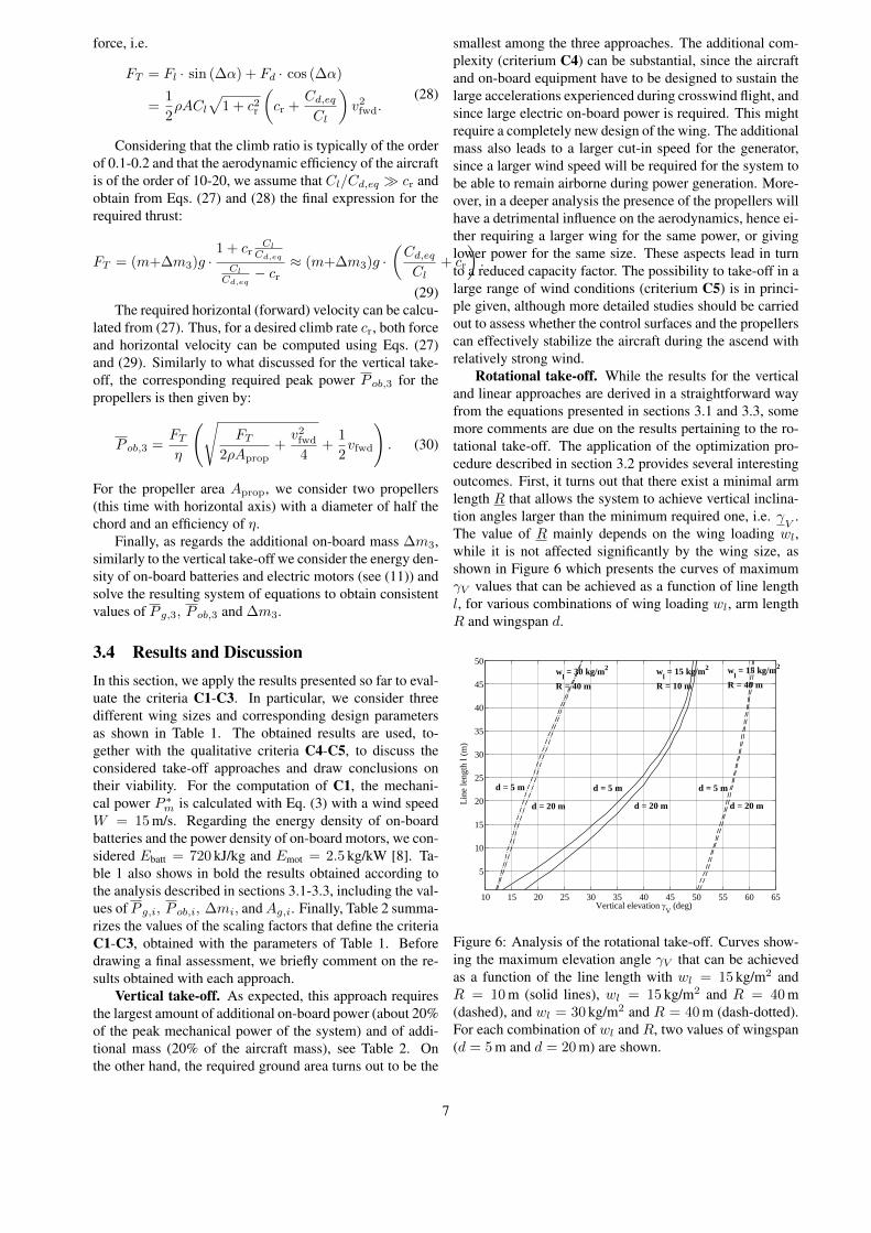
The value of R mainly depends on the wing loading wl,while it is not affected significantly by the wing size, asshown in Figure 6 which presents the curves of maximumγV values that can be achieved as a function of line lengthl, for various combinations of wing loading wl, arm lengthR and wingspan d.
10 15 20 25 30 35 40 45 50 55 60 65
5
10
15
20
25
30
35
40
45
50
Vertical elevation gV (deg)
Line
leng
thl(
m)
d = 5 m
d = 20 m
d = 5 m
d = 20 md = 20 m
d = 5 m
wl = 30 kg/m2
R = 40 m
wl = 15 kg/m2
R = 40 mwl = 15 kg/m2
R = 10 m
Figure 6: Analysis of the rotational take-off. Curves show-ing the maximum elevation angle γV that can be achievedas a function of the line length with wl = 15 kg/m2 andR = 10 m (solid lines), wl = 15 kg/m2 and R = 40 m(dashed), and wl = 30 kg/m2 and R = 40 m (dash-dotted).For each combination of wl and R, two values of wingspan(d = 5 m and d = 20 m) are shown.
7

Table 1: Design parameters for the assessment of the different take-off concepts. Bold-faced parameters are the resultsobtained according to the assumptions and analysis described in sections 3.1-3.3.
Parameter Aircraft 1 Aircraft 2 Aircraft 3Common parameters
Wing span d (m) 5 10 20Aspect ratio λ 10Chord d/λ (m) 0.5 1 2Wing area A (m2) 2.5 10 40Wing loading wl = m/A (kg/m2) 15Mass m0 (without additional equipment for take-off 37.5 150 600Lift coefficient Cl 1Drag coefficient Cd,eq 0.1Desired vertical velocity vc (m/s) 1Propeller efficiency η 0.7Peak mechanical power P ∗m with W = 15 m/s (kW) 75 300 1200
Vertical take-offTarget height h (m) 100Energy density of on-board batteries Ebatt (kJ/kg) 720Power density of on-board motors Emot (kW/kg) 2.5Propeller diameter d/λ (m) 0.5 1 2Peak additional on-board power P ob,1 (kW) 14 56 223Additional on-board mass ∆m1 (kg) 8 30 120Required ground area Ag,1 (m2) 20 80 315
Rotational take-offMaximum angle between the wingsand the plane perpendicular to the line ζ (deg) 50Reel-out speed of the line vl (m/s) 1.6Minimum vertical inclination γ
V(deg) 40
Maximum vertical inclination γV (deg) 90Minimum arm length R (m) 30Maximum arm length R (m) 50Optimal arm length Ropt (m) 50Maximal angular velocity ω (rad/s) 0.4Maximal tangential velocity of the tip of the arm ωR (m/s) 20Peak additional ground power P g,2 (kW) 3 12 47Additional on-board mass ∆m2 (kg) 0Required ground area Ag,2 (m2) 7854
Linear take-off with on-board propellersGround travel distance L (m) 12Target height h (m) 100Viscous friction coefficient cv (kg/s) 0.1 0.3 1Take-off speed v∗ (m/s) 15.7Propeller’s diameter d/(2λ) (m) 0.25 0.5 1Peak additional ground power P g,3 (kW) 8 31 124Peak additional on-board power P ob,3 (kW) 2 9 37Additional on-board mass ∆m3 (kg) 2 5 20Required ground area Ag,3 (m2) 132 192 428
8

Table 2: Results for the quantitative performance criteria C1, C2, and C3 (Eqs.(5)-(7) ) with the parameters of Table 1.C1: power C2: mass C3: area
Concept ηPg,i (%) ηPob,i (%) ηm,i (%) Ag,i ηAg,i (%)
Vertical 0 19 21 0 πλ4
Rotational 4 0 0 πR2
4 0
Linear 11 3 5 πL2
4πλ4
The main explanation for this phenomenon is that theaerodynamic forces have to counteract the centrifugal force(see section 3.2), which decreases as the arm length R in-creases. For the wing loading and minimal vertical inclina-tion values chosen for our comparison, i.e. wl = 15 kg/m2
and γV = 40◦, we obtain R ' 30 m, as reported in Table 1.Second, the required peak power increases with γV , since
the equilibrium conditions (18)-(19) become less favorableand a larger rotational speed is required to generate enoughlift to maintain the desired vertical inclination. This is shownin Figure 7. Hence, for the sake of minimizing the requiredadditional power, the minimum vertical inclination is cho-sen.
5 10 15 20 25 30 35 40 45 50 55 60 650.4
0.6
0.8
1
1.2
1.4
1.6
1.8
2
2.2
2.4
x 104
Vertical inclination gV (deg)
Peak
mec
hani
calp
ower
(W)
Figure 7: Analysis of the rotational take-off. Curves show-ing the peak ground mechanical power P ∗g,2 for l = 1 m as afunction of the elevation angle γV and with R = 10 m (thinsolid line), R = 20 m (dashed), R = 40 m (dash-dotted)and R = 80 m (thick solid line). The vertical dashed linesindicate the maximum elevation angle achievable for eachconsidered arm length. Wing span d = 10 m, wing loadingwl = 15 kg/m2.
Last, the peak mechanical power decreases with the armlength and approaches an asymptotic value. The reason isthat, as the centrifugal force decreases (i.e. R increases),the aerodynamic forces have to win just the aircraft weight.This condition leads asymptotically, for growing R, to aminimum required tangential speed and corresponding forceswhich then determine the required power to rotate the arm.The mentioned trend is shown in Figure 8. In order to re-strict our analysis to a finite value of R, we chose an upper
bound of R = 50 m, which is then the optimal value ac-cording to Eq. (23).
30 32 34 36 38 40 42 44 46 48 500
1
2
3
4
5
6
7
8
9x 10⁴
Arm length (m)
Mec
hani
calp
ower
(kW
)
Figure 8: Analysis of the rotational take-off. Curves show-ing the peak ground mechanical power P ∗g,2 for l = 1 mas a function of the arm length R for d = 5 m (solid),d = 10 m (dashed), and d = 20 m (dash-dotted). Wingloading wl = 15 kg/m2.
Due to the mentioned findings, the rotational start-upresults in the lowest value of peak ground and on-boardpower, as well as the lowest value of additional mass, buta very large ground-area occupation as compared with theother two approaches, see Tables 1-2. Such a land occu-pation is fundamentally linked to the wing loading as dis-cussed above, i.e. it is not possible to decrease the landoccupation below a minimum threshold by increasing theinstalled power or decreasing the wing size. As a matterof fact, the minimum ground occupation is quite large for areasonable wing loading.
As regards complexity (C4), this is expected to be large,considering that the system would feature a 50-m-long rigidarm whose tip rotates at about 20 m/s. Moreover, the wholemain winch should rotate as well with many full revolu-tions while at the same time reeling the line, which posesa challenge for the winch mechanics and the electrical con-nections. The manufacturing and installation costs of such astructure could be comparable to those of a traditional windturbine and appear to be prohibitive for the economic viabil-ity of the approach. Finally, about wind adaptation (C5) itis unclear how this concept would handle a strong prevalentwind during take-off, when the relative wind speed could
9

changes e.g. by ±10 m/s during a half turn, with the air-craft speed relative to ground of about 20 m/s.
Linear take-off. The required peak power installed onthe ground for this approach is larger than that of the ro-tational take-off, however with a significantly smaller re-quired area. Moreover, differently from the rotational take-off, in the linear take-off the ground area and required powercan be easily traded off. As regards the on-board power andadditional mass, they result to be about six times smallerthan for the vertical take-off. The required ground occu-pation is comparable to the vertical take-off and dominatedby the wing size when scaling up, hence it turns out to bequite favorable. About the complexity of the approach, thisappears to be small, since in principle one could envisiona solution where the winch used to generate power is alsoemployed in the initial phase of the take-off, e.g. by meansof a clutch to (dis-) engage a linear motion system to ac-celerate the aircraft. Similarly, the on-board propellers andbatteries are necessary in any case to power the on-boardcontrol systems, hence the use of slightly larger and morepowerful on-board motors does not appear to be critical.Moreover, the on-board propellers can also be used to re-charge the batteries to supply energy to the control systemduring long periods of power generation. Finally, since thewhole setup can be turned, the take-off is independent ofthe current prevalent wind direction.
Discussion. The results presented so far indicate thatboth the vertical and the rotational take-off require exten-sive modifications of the AWE system, which will have astrong influence on the design and require significant ad-ditional equipment. On the other hand, the linear take-offapproach will have less impact on the system design. If themain winch can also be used for the acceleration phase, theadditionally required equipment is in fact reduced to a min-imum. In terms of mechanical power, the linear take-offprovides a good tradeoff between on-board and on-groundpower. Moreover the additional on-board components likebatteries and small propellers will have further applications,like powering the on-board electronics. Finally, the land oc-cupation of the linear take-off is almost as small as that ofthe vertical one. For these reasons, we favor the linear take-off for rigid-wing AWE systems with ground-based electricgeneration. This approach will be analysed in more detailin the following section.
4 Simulation of a linear take-off ap-proach
In this section, we further study, by means of numericalsimulations, the linear take-off combining ground motorsand on-board propellers. We first introduce a dynamicalmodel of the system, then we describe the control algo-rithms to carry out the take-off maneuver, finally we presentthe simulation results and compare them with the static equa-tions derived in section 3.3.
4.1 A dynamical model for linear take-offWe consider a ground unit composed of a winch, where theaircraft’s tether is coiled, and of a linear motion system,whose aim is to accelerate the aircraft up to take-off speed,see Figure 9. The winch rotation is controlled by a gearedmotor/generator M1, which is the main electrical machineof the AWE system, responsible for converting mechani-cal power into electricity during the power generation cy-cles. The linear motion system consists of a slide, carryingthe aircraft during take-off, that can move along rails. Theslide motion is controlled by a second geared motor M2
through a transmission system (e.g. a belt). The slide isequipped with sheaves that guide the tether from the winchto the attachment point on the aircraft. This system can bewell described by a hybrid dynamical model: a first oper-ating mode (Figure 9(a)) describes the system’s behaviorfrom zero speed up to the take-off, when the aircraft andthe slide can be considered as a unique rigid body; a sec-ond operating mode (Figure 9(b)) describes the aircraft mo-tion after take-off, when it is separated from the slide. Forthe sake of simplicity, we consider a two-dimensional mo-tion only in the second mode, i.e. vertical and horizontaldisplacements and pitch rotation of the aircraft, assumingthat suitable stabilizing systems act on the on-board actua-tors (rudder and ailerons) in order to keep the roll and yawangles at small values, counteracting potential lateral windturbulence. Moreover, we assume that no wind opposite tothe take-off direction is present, i.e. the take-off is carriedout only by means of the ground motors and on-board pro-pellers. In case of substantial wind, we assume the systemto be capable to orient the rails according to the wind di-rection to take advantage of the additional apparent windvelocity, hence reducing the take-off speed. Thus, the con-ditions simulated here provide the worst-case in terms ofrequired power, in line with the analysis of section 3.3. Allthe equations presented in the following have been derivedby applying Newton’s second law of motion.
The state of the model, i.e. the variables that describecompletely and univocally its configuration at any time in-stant t, is given by x(t)
.= [ϑM1
(t), ϑM1(t), ϑM2
(t), ϑM2(t),
xg(t), xg(t), yg(t), yg(t), ϑg(t), ϑg(t)]T , where ϑM1
isthe angular position of the winch, ϑM1
.=
dϑM1
dt its an-gular speed, ϑM2
, ϑM2are the angular position and speed
of the motor that controls the linear motion system, xg(t),xg(t), yg(t), yg(t), the horizontal (x) and vertical (y) po-sitions and speeds of the aircraft’s center of gravity in aninertial reference frame. The latter has its center at thepoint where the tether exits the winch, the xg-axis paral-lel to the ground and the yg-axis vertical and pointing up-wards (see Figure 9). Finally, ϑg(t), ϑg(t) are the aircraft’spitch angle and its rate. The manipulated inputs availableto control and operate the system are denoted with u(t)
.=
[CM1(t), CM2
(t), FT (t)]T whereCM1, CM2
are the torquesapplied by the two electrical machines, and FT is the thrustforce exerted by the on-board propeller. The motor torquesconsidered in the model are taken after any gear that canbe installed between the motor and the winch (respectivelythe belt’s pulley) to adapt the motor’s torque/speed profile
10

ߴ
M1 M2
ଵߴ
௦ݔ
ଶߴ
M1 M2
ଵߴ
௦ݔ
ଶߴ
(a)
(b)
ݔ
ݕ
ݔ
ݕ
Figure 9: Sketch of the system considered to simulate thelinear take-off procedure. (a) First operating mode, with theaircraft carried by the slide up to take-off speed; (b) secondoperating mode, with the aircraft gaining altitude by meansof the on-board propeller.
to the application. In the following, for the sake of simplic-ity we denote with xj (resp. uj) the jth component of thestate (resp. input) vector defined above. Assuming that thelinear motion system is realized by a belt, driven by a pulleydirectly attached to the shaft of motor M2, and neglectingits elasticity, the model is given by the following equationsin the first operating mode:
x1(t) = x2(t)
x2(t) =1
JM1
(rM1T (t)− βM1
x2(t) + u1(t))
x3(t) = x4(t)
x4(t) =1
JM2 + (ms +m) r2M2
(rM2 (−T (t)+
−Fd(t) cos(∆α(t))++Fl(t) sin(∆α(t))− βs rM2 x4(t))−βM2 x4(t) + u2(t))
x5(t) = x6(t)x6(t) = rM2
x4(t)x7(t) = x8(t)x8(t) = 0x9(t) = x10(t)x10(t) = 0.
(31)In (31), rM1
is the radius of the winch (assuming for sim-plicity that the latter is directly connected to the motor/generator),rM2 the radius of the pulley that links motor M2 to the belt,JM1
, JM2the moments of inertia of the winch and of the
pulley plus their respective motors, βM1, βM2
their viscousfriction coefficients, ms the mass of the slide, βs the vis-cous friction coefficient of the belt/slide/rail system, m themass of the aircraft. The angle ∆α is defined as:
∆α(t) = arctan
(−ygxg
), (32)
i.e. the angle between the velocity vector of the aircraft and
-0.1 -0.05 0 0.05 0.1 0.15 0.2 0.25 0.3-0.2
0
0.2
0.4
0.6
0.8
1
Angle of attack a (rad)
Lift
coef
ficie
nt,D
rag
coef
ficie
nt
Figure 10: Lift (solid line) and drag (dashed) coefficientsused in the dynamical simulation model of the take-offphase, and initial wing trimming ϑ0 (dash-dotted line).
the inertial xg-axis, measured positive if the yg-axis com-ponent of the velocity is negative, i.e. if the aircraft is de-scending. T is the tension force on the tether:
T (t) = min (0, kt (‖(xg(t), yg(t))‖2 − rM1x1(t))) ,
(33)where kt is the stiffness of the tether, assumed constant forsimplicity. The saturation to 0 in Eq. (33) accounts for thefact that the tether can only transfer force when under ten-sion, i.e. when its length rM1
x1(t) is smaller than the po-sition of the aircraft relative to its attachment point on theground. Finally, Fl and Fd are, respectively, the aerody-namic lift and drag forces developed by the aircraft, com-puted as:
Fl(t) = 12ρACl(α(t)) · ‖(xg(t), yg(t))‖22
Fd(t) = 12ρACd,eq(α(t)) · ‖(xg(t), yg(t))‖22
(34)
where α(t) is the angle of attack:
α(t) = ϑ0 + ∆α(t) + x9(t). (35)
The angle ϑ0 is a fixed setting for the wings’ orientation,such that if the aircraft is flying horizontally (i.e. ∆α = 0)at zero pitch angle then we have α = ϑ0. The consideredcourses of Cl, Cd as a function of α are shown in Figure 10and correspond to a finite wing with Clark-Y profile [32].The same figure also shows the chosen trimming for ϑ0.
We denote the initial state with xI0, which is required tosimulate the model (31), i.e. x(0) = xI0. In particular, wechoose the initial condition
xI0 =
[l0rM1
, 0, 0, 0, xg,0, 0, 0, 0, 0, 0
]T, (36)
meaning that the motors, the slide and the aircraft are ini-tially at rest, a length l0 of tether is reeled out and the dis-tance of the aircraft’s starting position from the attachmentpoint of the line on the winch is equal to xg,0, with xg,0 > l0
11

so that the tether is not exerting any force on the glider andthe slide (see Eq. (33)).
The switch between the first and the second operatingmodes takes place at the time instant t∗ defined as:
t∗ = min (τ ≥ 0 : Fl(τ) cos(∆α(τ)) > mg) . (37)
Thus, t∗ represents the time instant when the vertical liftforce developed by the glider is larger than its weight, henceobtaining a positive vertical acceleration. The initial condi-tion xII0 of the model that describes the system in the secondoperating mode is then given by:
xII0 = x(t∗), (38)
i.e. the state of the system in the first operating mode at theswitching instant t∗. The model equations for the secondoperating mode are the following:
x1(t) = x2(t)
x2(t) =1
JM1
(rM1 T (t)− βM1 x2(t) + u1(t))
x3(t) = x4(t)
x4(t) =1
JM2+ms r2M2
(−r2M2βs x4(t)− βM2
x4(t)
+u2(t))x5(t) = x6(t)
x6(t) =1
m+mt(t)(Fl(t) sin(∆α(t))
−Fd(t) cos(∆α(t)) + cos(x9(t))u3(t))x7(t) = x8(t)
x8(t) =1
m+mt(t)(Fl(t) cos(∆α(t))
+Fd(t) sin(∆α(t))−(m+mt(t)) g + sin(x9(t))u3(t))
x9(t) = x10(t)x10(t) = ωβ(−∆α(t)− x10(t)),
(39)where mt is the mass of the tether that has been reeled out:
mt(t) = ρt π r2t rM1 x1(t) (40)
with ρt and rt being respectively the density and the radiusof the tether. Regarding the last two equations in Eq. (39),which describe the behavior of the pitch angle, we assumefor simplicity that an active control system actuates the el-evator in order to track the angle ϑg,ref
.= −∆α(t) with
no offset, and that the resulting closed-loop dynamical be-havior is given by a first-order system with time constant1ωβ
, where ωβ is a constant parameter. In this way, if asteady state is attained during the ascend, the correspondingangle of attack will match the parameter ϑ0, see Eq. (35).Note that the pitch angle ϑg (i.e. x9) affects how the thrustforce u3 exerted by the propeller acts on the horizontal andvertical dynamics of the aircraft, hence providing a furthercoupling between the pitch dynamics and the aircraft trans-lational motion.
Eqs. (31)-(40) provide the hybrid model that we use torefine the results given in section 3. However, this modelcannot be simulated without first implementing suitable feed-back controllers, since the open-loop behavior of the systemis not stable. In the next section, we briefly describe the con-trollers we employ to carry out the numerical simulations.
4.2 Control designThe control objectives are different between the first andsecond operating mode. In the first mode, the winch mo-tor M1 has to accelerate fast enough, such that the tethertension is always zero, but avoiding at the same time thatan excessive tether length is reeled-out, to limit the line sag.At the same time, the slide motorM2 has to accelerate fromzero to take-off speed. To achieve these goals, we employthe following proportional controllers:
u1(t) = KM1(xg,to − rM1
x2(t))u2(t) = KM2(xg,to − rM2 x2(t))
(41)
where KM1, KM2
are the controllers’ gains, and xg,to is areference speed.
In the second operating mode, the winch motorM1 shallmaintain a reel-out speed that matches that of the aircraft,again to keep the tether tension at a low value. The motorM2 shall brake and stop the slide. Finally, the on-boardpropeller shall track a desired vertical velocity yg,to. Toobtain these goals, we employ the following proportionalcontrollers for the motors:
u1(t) = KM1(‖(xg(t), yg(t))‖2 − rM1
x2(t))u2(t) = −KM2rM2 x2(t),
(42)
while for the propeller we implement a dynamical cascadecontroller whose transfer function in the Laplace domain isthe following
C(s).=
U3(s)
Eyg (s)= KT
(1 + s
wz,1
)(1 + s
wz,2
)s(
1 + swp
) (43)
where s is the Laplace variable, U3(s) and Eyg (s) are theLaplace transforms of the propeller thrust signal u3(t) andof the tracking error eyg (t)
.= yg,to−yg(t), respectively, and
KT , wz,1, wz,2 andwp are design parameters. The need forthe slightly more complex controller (43) for the propeller,with respect to the simple proportional gains (41)-(42) usedfor the motors, stems from the presence of additional dy-namics in the glider, for example due to the interaction be-tween the pitch dynamics and the translational motion, thatneed to be compensated in order to avoid an oscillatory be-havior of the system’s response. All three inputs u1, u2, u3are saturated due to physical limitations of the motors:
−CM1≤ u1(t) ≤ CM1
−CM2≤ u2(t) ≤ CM2
0 ≤ u3(t) ≤ FT(44)
Finally, the described controllers are implemented in dis-crete time with a sampling frequency of 100 Hz.
4.3 Simulation results and discussionWe simulate the take-off maneuver for three different air-crafts, whose effective areas matches those considered insection 3. The model and control parameters employed forthe simulations are shown in Tables 3 and 4, respectively.In addition, the values ρ = 1.2 kg/m3, g = 9.81 m/s2 and
12

Table 3: System parameters employed to simulate the take-off maneuver.
d (m) 5 10 20JM1 (kg m2) 1.3 30 490βM1
(kg/s) 0.001 0.002 0.003rM1
(m) 0.2 0.5 1JM2 (kg m2) 0.03 0.1 2βM2
(kg/s) 0.001 0.002 0.003rM2
(m) 0.1 0.15 0.4ms (kg) 6 30 120m (kg) 37.5 150 600βs (kg/s) 0.1 0.3 1kt (N/m) 1 105 9.1 105 2.5 105
rt (m) 0.0025 0.0075 0.0125ρt (kg/m3) 970 970 970ωβ (rad/s3) 10 10 10ϑ0 (rad) 0.24 0.24 0.24
Table 4: Control parameters employed to simulate the take-off maneuver.
d (m) 5 10 20xg,to (m/s) 30 30 30yg,to (m/s) 1 1 1KM1 (N m s/rad) 3 20 160KM2 (N m s/rad) 10 50 200KT (N m s/rad) 100 150 600ωp (rad/s) 16 32 32ωz,1 (rad/s) 0.2 0.2 0.2ωz,2 (rad/s) 1 2 2CM1
(N m) 750 3000 12000CM2 (N m) 48 290 3500FT (N) 80 350 600
the aerodynamic coefficients shown in Figure 10 have beenused. The initial conditions (36) with l0 = 2 m and xg,0 = 0were used for all three aircrafts. The number and size of thepropellers, required to compute the related power accord-ing to equation (10), are the same as those considered insection 3, i.e. 2 propellers with efficiency 0.7 and 0.25 m,0.5 m, 1 m of diameter, respectively, for the three aircraftsizes.
Examples of simulation results for the aircraft with d =10 m are shown in Figures 11-14. In Figure 11, it can benoted that the total travel distance of the slide is equal to 15m, and that the aircraft starts the ascend after 12.4 m, i.e.when the take-off speed of 15.7 m/s has been reached. Asshown in Figure 12, the motor M2 exploits the full ratedtorque to accelerate and then to brake the slide, while M1
employs a relatively small fraction of its available torquefor the acceleration and then settles to a constant torque cor-responding to the viscous friction at the aircraft’s velocity.We remark that the power required to accelerate the drum,although substantial, does not give rise to additional costs,since the machine M1 is already present and the power re-quired for take-off is a small fraction of the one that occursduring power generation. The propeller is engaged only af-
0 3 6 9 12 150
5
10
15
20
25
30
time (s)
Posi
tion
Aircraft height (m)Slide position (m)Aircraft position (10 m)
Figure 11: Simulation results with the 10-m-wingspan air-craft. Courses of the aircraft height, slide position and air-craft distance from the ground station (divided by 10 for thesake of clarity).
0 3 6 9 12 15-400
-200
0
200
400
600
800
1000
time (s)
Torq
ue(N
m),
Forc
e(N
)Slide motor (Nm)Winch motor (Nm)Propeller (N)
Figure 12: Simulation results with the 10-m-wingspan air-craft. Courses of the motor torques and of the propellerthrust.
ter take-off and, after a short transient, it settles to a steadyvalue sufficient to achieve the desired vertical velocity. Thebehavior of the latter quantity as compared with its refer-ence is reported in Figure 13. As shown in Figure 14, thepeak power for the motors is reached at the instant whenthe aircraft takes off. The results obtained with the othertwo aircrafts (d = 5 and 20 m) are qualitatively similar tothose shown in Figures 11-14. In all cases, the total traveldistance of the slide was about 15 m.
Table 5 shows a comparison between the power figuresobtained from the simplified analysis of section 3 and thoseobtained with the simulations. The values of power requiredon the ground are very well matching, hence confirmingthe outcome of our simplified analysis. The larger simu-lated values for the required on-board power, with respectto the simplified analysis, are due to the inertia of the air-
13

Table 5: Comparison between the power values provided by the simplified equations and those provided by the numericalsimulations. The percentages in brackets refer to the peak mechanical power of the generator with 15 m/s wind speed.
Wingspan (m) 5 10 20Ground motor (kW) - simple equation 8 (11%) 31 (10%) 124 (10%)Ground motor (kW) - simulation 8 (11%) 30 (10%) 140(11%)Propeller (kW) - simple equation 2 (3%) 9 (3%) 37 (3%)Propeller (kW) - simulation 3 (4%) 13 (4%) 50 (4%)
0 3 6 9 12 150
0.1
0.2
0.3
0.4
0.5
0.6
0.7
0.8
0.9
1
1.1
time (s)
Ver
tical
spee
d(m
/s)
Figure 13: Simulation results with the 10-m-wingspan air-craft. Course of the vertical speed of the aircraft (solid) andthe target value (dashed).
0 3 6 9 12 15
-3
-2
-1
0
1
2
3
x 104
time (s)
Pow
er(W
)
Slide motorWinch motorPropeller
Figure 14: Simulation results with the 10-m wingspan air-craft. Courses of the motors’ and propeller’s power.
craft, which plays a role in the transient from zero verticalspeed to the target one (see Figure 12), and due to its pitch,which has the effect of decreasing the thrust in horizontaldirection and adding a braking contribution from the liftforce projected onto the xg−axis. Again, notwithstandingthese effects, the on-board power required for the ascendappears to be a reasonable fraction of the system’s power.
Moreover, we did not carry out any optimization neither ofthe design parameters nor of the controllers, which can stillbe adjusted in order to achieve different tradeoffs betweenpeak power consumption and velocity of the transient fromzero to the target vertical speed.
5 ConclusionsWe presented an analysis of different concepts for the take-off phase of AWE systems based on rigid wings and ground-level power conversion, by means of basic equations. Basedon the analysis, we concluded that a linear take-off ma-neuver with a ground acceleration phase and on-board pro-pellers is the most viable approach. We refined the anal-ysis of this maneuver by means of numerical simulationswith a hybrid dynamical model. The simulation results pre-dict slightly larger on-board power values than the simpli-fied analysis, but still they are small compared to the to-tal power of the generator. This indicates that the take-offequipment constitutes a rather small cost fraction of the to-tal system costs. At the same time, the required land occu-pation appears to be reasonable. These outcomes confirmthe technical and economic feasibility of this take-off tech-nique. Further studies will be devoted to a deeper analysisof the approach and to the study of the landing maneuver,both with finer dynamical models, also accounting also forwind turbulence, and with experimental activities.
References[1] Ampyx Power website,
http://www.ampyxpower.com/.
[2] TwingTec website, http://www.twingtec.ch.
[3] Enerjite Gmbh website, http://www.enerkite.com/.
[4] U. Ahrens, M. Diehl, and R. Schmehl, editors. Air-borne Wind Energy. Green Energy and Technology.Springer-Verlag Berlin, 2014.
[5] C.L. Archer. Airborne Wind Energy, chapter 5. An In-troduction to Meteorology for Airborne Wind Energy,page 81. Green Energy and Technology. Springer-Verlag, Berlin, 2014.
[6] C.L. Archer and K. Caldeira. Global assessment ofhigh-altitude wind power. Energies, 2(2):307–319,2009.
14

[7] J. H. Baayen and W. J. Ockels. Tracking control withadaption of kites. IET Control Theory and Applica-tions, 6(2):182–191, 2012.
[8] Eelke Bontekoe. Up! - how to launch and re-trieve a tethered aircraft. Master’s thesis, TUDelft, August 2010. Accessed in August 2015 athttp://repository.tudelft.nl/.
[9] A. Bormann, M. Ranneberg, P. Kövesdi, C. Gebhardt,and S. Skutnik. Airborne Wind Energy, chapter 24.Development of a Three-Line Ground-Actuated Air-borne Wind Energy Converter, page 427. Green En-ergy and Technology. Springer-Verlag, Berlin, 2014.
[10] A. Bosch, R. Schmehl, P. Tiso, and D. Rixen. AirborneWind Energy, chapter 17. Nonlinear Aeroelasticity,Flight Dynamics and Control of a Flexible MembraneTraction Kite, page 307. Green Energy and Technol-ogy. Springer-Verlag, Berlin, 2014.
[11] A. Bosch, R. Schmehl, P. Tiso, and D. Rixen. Dy-namic nonlinear aeroelastic model of a kite for powergeneration. AIAA Journal of Guidance, Control andDynamics, 37(5):1426–1436, 2014.
[12] J. Breukels, R. Schmehl, and W. Ockels. AirborneWind Energy, chapter 16. Aeroelastic Simulation ofFlexible Membrane Wings based on Multibody Sys-tem Dynamics, page 287. Green Energy and Technol-ogy. Springer-Verlag, Berlin, 2014.
[13] M. Canale, L. Fagiano, and M. Milanese. High al-titude wind energy generation using controlled powerkites. IEEE Transactions on Control Systems Technol-ogy, 18(2):279 –293, mar. 2010.
[14] Michael Erhard and Hans Strauch. Flight control oftethered kites in autonomous pumping cycles for air-borne wind energy. Control Engineering Practice,submitted. preprint available on arXiv:1409.3083.
[15] Michael Erhard and Hans Strauch. Control of towingkites for seagoing vessels. IEEE Transactions on Con-trol Systems Technology, 21(5):1629 – 1640, 2013.
[16] R. H. Luchsinger F. Gohl. Airborne Wind Energy,chapter 18. Simulation Based Wing Design for KitePower, page 325. Green Energy and Technology.Springer-Verlag, Berlin, 2014.
[17] L. Fagiano, K. Huynh, B. Bamieh, and M. Khammash.On sensor fusion for airborne wind energy systems.IEEE Transactions on Control Systems Technology,22(3):930–943, 2014.
[18] L. Fagiano and T. Marks. Design of a small-scale prototype for research in airborne wind en-ergy. IEEE/ASME Transactions on Mechatronics,20(1):166–177, 2014.
[19] L. Fagiano and M. Milanese. Airborne wind energy:an overview. In American Control Conference 2012,pages 3132–3143, Montreal, Canada, 2012.
[20] L. Fagiano, M. Milanese, and D. Piga. High-altitudewind power generation. IEEE Transactions on EnergyConversion, 25(1):168 –180, mar. 2010.
[21] L. Fagiano, M. Milanese, and D. Piga. Optimization ofairborne wind energy generators. International Jour-nal of Robust and Nonlinear Controll, 2011. In press,early view available. doi: 10.1002/rnc.1808.
[22] L. Fagiano, A.U. Zgraggen, M. Morari, and M. Kham-mash. Automatic crosswind flight of tethered wingsfor airborne wind energy: modeling, control designand experimental results. IEEE Transactions on Con-trol Systems Technology, 22(4):1433–1447, 2014.
[23] U. Fechner and R. Schmehl. Feed-forward control ofkite power systems. Journal of Physics: ConferenceSeries, 524:012081, 2014.
[24] F. Fritz. Airborne Wind Energy, chapter 20. Applica-tion of an Automated Kite System for Ship Propulsionand Power Generation, page 359. Green Energy andTechnology. Springer-Verlag, Berlin, 2014.
[25] J. H. Horlock. Actuator Disk Theory: Discontinuitiesin Thermo Fluid Dynamics. McGraw-Hill, 1978.
[26] B. Houska and M. Diehl. Optimal control for powergenerating kites. In 9th European Control Conference,pages 3560–3567, Kos, GR, 2007.
[27] R. Leloup, K. Roncin, G. Bles, J.B. Leroux,C. Jochum, and Y. Parlier. Airborne Wind Energy,chapter 19. Estimation of the Lift-to-Drag Ratio Us-ing the Lifting Line Method: Application to a Lead-ing Edge Inflatable Kite, page 339. Green Energy andTechnology. Springer-Verlag, Berlin, 2014.
[28] D. Vander Lind. Airborne Wind Energy, chapter 28.Analysis and Flight Test Validation of High Perfor-mance Airborne Wind Turbines, page 473. Green En-ergy and Technology. Springer-Verlag, Berlin, 2014.
[29] M. L. Loyd. Crosswind kite power. Journal of Energy,4(3):106–111, 1980.
[30] Makani Power Inc. http://www.makanipower.com.
[31] M. S. Manalis. Airborne windmills and communi-cation aerostats. Journal of Aircraft, 13(7):543–544,1976.
[32] Barnes W. Mccormick. Aerodynamics, Aeronautics,and Flight Mechanics. John Wiley and Sons, 1995.
[33] M. Milanese, F. Taddei, and S. Milanese. AirborneWind Energy, chapter 21. Design and Testing of a60 kW Yo-Yo Airborne Wind Energy Generator, page373. Green Energy and Technology. Springer-Verlag,Berlin, 2014.
[34] R. Ruiterkamp and Sören Sieberling. Airborne WindEnergy, chapter 26. Description and Preliminary TestResults of a Six Degrees of Freedom Rigid Wing
15

Pumping System, page 443. Green Energy and Tech-nology. Springer-Verlag, Berlin, 2014.
[35] J. Stuyts, G. Horn, W. Vandermeulen, J. Driesen, andM. Diehl. Effect of the electrical energy conversionon optimal cycles for pumping airborne wind energy.IEEE Transactions on Sustainable Energy, 6(1):2–10,2015.
[36] R. van der Vlugt, J. Peschel, and R. Schmehl. Air-borne Wind Energy, chapter 23. Design and Exper-imental Characterization of a Pumping Kite PowerSystem, page 403. Green Energy and Technology.Springer-Verlag, Berlin, 2014.
[37] C. Vermillion, B. Glass, and A. Rein. Airborne WindEnergy, chapter 30. Lighter-Than-Air Wind EnergySystems, page 501. Green Energy and Technology.Springer-Verlag, Berlin, 2014.
[38] M. Zanon, S. Gros, and M. Diehl. Rotational start-upof tethered airplanes based on nonlinear mpc and mhe.In European Control Conference (ECC) 2013, pages1023–1028, Zuerich, Switzerland, July 2013, 2013.
[39] M. Zanon, S. Gros, and M Diehl. Airborne WindEnergy, chapter 12. Model Predictive Control ofRigid-Airfoil Airborne Wind Energy Systems, page219. Green Energy and Technology. Springer-Verlag,Berlin, 2014.
[40] A.U. Zgraggen, L. Fagiano, and M. Morari. Real-timeoptimization and adaptation of the crosswind flight oftethered wings for airborne wind energy. IEEE Trans-actions on Control Systems Technology, 23(2):434–448, 2015.
[41] U. Zillmann and S. Hach. Airborne Wind Energy,chapter 7. Financing Strategies for Airborne WindEnergy, page 117. Green Energy and Technology.Springer-Verlag, Berlin, 2014.
16