on the thermal and kinetic performance of a coal-co2 slurry-fed
TRANSCRIPT
On the Thermal and Kinetic Performance of a Coal-CO2 Slurry-fed Gasifier:Optimization of CO
2
and H2
O flow using CO2
skimming and steam injection
Cristina Botero∗, Randall P. Field, Howard J. Herzog, Ahmed F. Ghoniem
Massachusetts Institute of Technology, 77 Massachusetts Avenue, Cambridge, MA 02139
Abstract
Coal-CO2 slurry feed provides significant thermal advantages when compared to conventional coal-waterslurry for feeding pressurized entrained-flow gasifiers, assuming complete carbon conversion. However, sub-stituting H2O by CO2 in the feeding system a↵ects the heterogeneous gasification kinetics and could reducecarbon conversion. This work examines CO2 slurry skimming, or flashing, in combination with steam in-jection, as a way to increase conversion by controlling and optimizing the flow of CO2 and H2O enteringthe reactor. We use multiscale computational tools developed at MIT to examine the thermal and kineticperformance of a gasifier with CO2 and H2O injection and quantify how it a↵ects the overall plant economics.The gasifier is part of a plant producing clean syngas with a H2:CO ratio of 2.0 after water-gas shift. Theslurry feeding system uses the Phase Inversion-based Coal-CO2 Slurry (PHICCOS) method to prepare coal-CO2 slurry from bituminous coal and lignite. The results show that the minimum syngas production cost is$132.9/kNm3 for bituminous coal and $128.6/kNm3 for lignite when the gasifier operates with a fixed outlettemperature of 1,400� and 1,300�, respectively. This economic optimum is achieved when CO2 skimmingto dry feed conditions is combined with the injection of 0.23 kg of steam per kg of coal (dry basis). Multi-variable optimization is currently being conducted to include the e↵ect of reactor temperature, among otherimportant operating and design variables, into the optimization process. The e↵ect of uncertain parameterson the process technoeconomics is also being studied.
Keywords: Coal, Gasification, Slurry, CO2, Technoeconomics
1. Introduction
Coal-water slurry (CWS) is currently the least capital-intensive technology for feeding pulverized coalinto a pressurized entrained-flow gasifier (EFG) [1]. Unlike lock-hopper-based dry feeding systems, CWSis attractive because of its simplicity and the high pressures that it can achieve. Nonetheless, heating upliquid water to the high temperature of >1300� at which EFGs typically operate requires large amountsof thermal energy. Slurry-fed EFGs are thus ine�cient, when compared to dry feeding systems, which isespecially problematic for low-rank coal. Besides increasing fuel consumpution, this leads to high capital andoperating costs in the air separation unit (ASU) required to supply O2 for autothermal reactor operation.
Coal-CO2 slurry is being studied as a more e�cient alternative to CWS feed in plants with carbon capture[2–6]. Liquid CO2 -or supercritical CO2 with liquid-like density- is available in such plants and is especiallyappealing as a slurrying medium as a result of its lower enthalpy of vaporization, heat capacity, and viscosity,among others [4].
The thermodynamic benefits of CO2 slurry feed are significant: a gasifier with this feeding system andcomplete carbon conversion is predicted to have an 11%-points (%-pt.) higher cold gas e�ciency (CGE)than one with CWS feed, for lignite, and a 7%-pt. advantage for bituminous coal [4]. The CGE for the latteris 82%, on a higher heating value basis, and is hence in the same range as the 78-83% typical for commerciallock-hopper based dry-fed reactors [7].
∗Corresponding authorEmail address: [email protected] (Cristina Botero)
38
th
International Technical Conference on Clean Coal and Fuel Systems, Clearwater (FL), USA, June 2-6 2013
Slurry preparation has proved to be a challenging step in a coal-CO2 slurry-fed system. The PhaseInversion-based Coal-CO2 Slurry (PHICCOS) preparation and feeding system has been proposed as a wayto address this challenge [5, 8]. Unlike other slurry preparation methods being studied [2], the PHICCOSsystem operates at ambient temperature and without the use of lock hoppers.
Despite the thermodynamic appeal of liquid CO2 in the feeding system, recent work has shown thatinjecting CO2 instead of H2O with the feed leads to the production of high concentrations of CO in thegasifier. This slows down the heterogeneous gasification kinetics directly, through inhibition of the steamand CO2 gasification reactions, as well as indirectly, through a slower di↵usion of reactants and productsin the pores of the pulverized coal particles. Once this is accounted for, a 7%-pt. reduction in the carbonconversion is predicted in a gasifier operating with CO2 slurry, relative to a reactor with CWS feed and thesame volume and outlet temperature [6].
The conversion reduction caused by the presence of CO2 has a significant impact on the gasifier per-formance. For example, for bituminous coal, once the conversion reduction is accounted for, the CGE ofa gasifier with CO2 slurry feed is the same as that of a CWS-fed gasifier, i.e. no performance advantageis predicted. The gasifier outlet temperature must be raised by over 100K to make up for the conversionreduction. This increases oxygen consumption by 10-20%, further contributing to the already high capi-tal and operating costs incurred in the ASU. The overall economic attractiveness of increasing the gasifiertemperature as a means to raise conversion in a coal-CO2 slurry-fed reactor is currently being studied.
As an alternative to, or in addition to, increasing the reactor temperature, the carbon conversion in aCO2 slurry-fed gasifier could be increased by addressing the actual source of the slower gasification kinetics:the fraction of CO2 in the gasification agent. This fraction can be reduced by either injecting less CO2 ormore H2O into the reactor, both of which can be practically implemented.
The flow of CO2 entering the gasifier can be reduced by flashing -or evaporating- CO2 from the pressurizedcoal-CO2 slurry. This process, which has been suggested in the past and is also known as CO2 skimming[9], requires only a small amount of thermal energy, if any, due to the proximity of CO2 in the slurry to itssaturation line. Furthermore, the flow of H2O in the feed can be increased by injecting steam to the gasifierin a way similar to how dry-fed gasifiers operate.
This work uses multiscale analysis to evaluate the technoeconomics of CO2 skimming and steam injectionas a way to control the fraction of CO2 and H2O in the feed of a PHICCOS-fed gasifier. The thermal benefitsof CO2 are combined with the kinetic benefits of H2O in order to optimize plant economics. The finalproduct is clean syngas with a H2:CO ratio of 2.0 after water-gas shift, which can be used for the productionof synthetic liquid fuels. The only application-specific component of this analysis is the H2:CO ratio of thesyngas, which can be adjusted without major hurdles in the shift reactor. Hence, the results of this studyare applicable to any syngas application, including the production of synthetic fuels and chemicals, as well aspower generation in an Integrated Gasification Combined Cycle (IGCC) power plant with carbon capture.
This paper begins by discussing the motivation for studying gasification in an environment of mixed CO2
and steam. A PHICCOS-fed gasifier with CO2 skimming and steam injection is introduced as an attractiveplatform to do this. The modeling methodology and tools used for the analysis are then presented. This isfollowed by a discussion of the main findings, which show that an optimum flow of CO2 and H2O exists, whichis a tradeo↵ between kinetics, thermodynamics, and costs and leads to the most favorable plant economics.The work concludes with an insight into the main challenges associated with the proposed feeding systemand an overview of ongoing and future work.
2. Gasification in a Mixed Environment of H2O and CO2
The motivation behind combining CO2 and steam injection in an EFG can be better understood byconsidering the chemical and thermal processes taking place inside an autothermal reactor and how thesea↵ect its performance.
2.1. Thermochemistry in an autothermal entrained-flow gasifier
The main gasification reactions occurring in an EFG are the steam-gasification and CO2-gasification(Boudouard) reactions. These yield a mixture of H2 and CO known as synthesis gas, or syngas, and are
2
given by
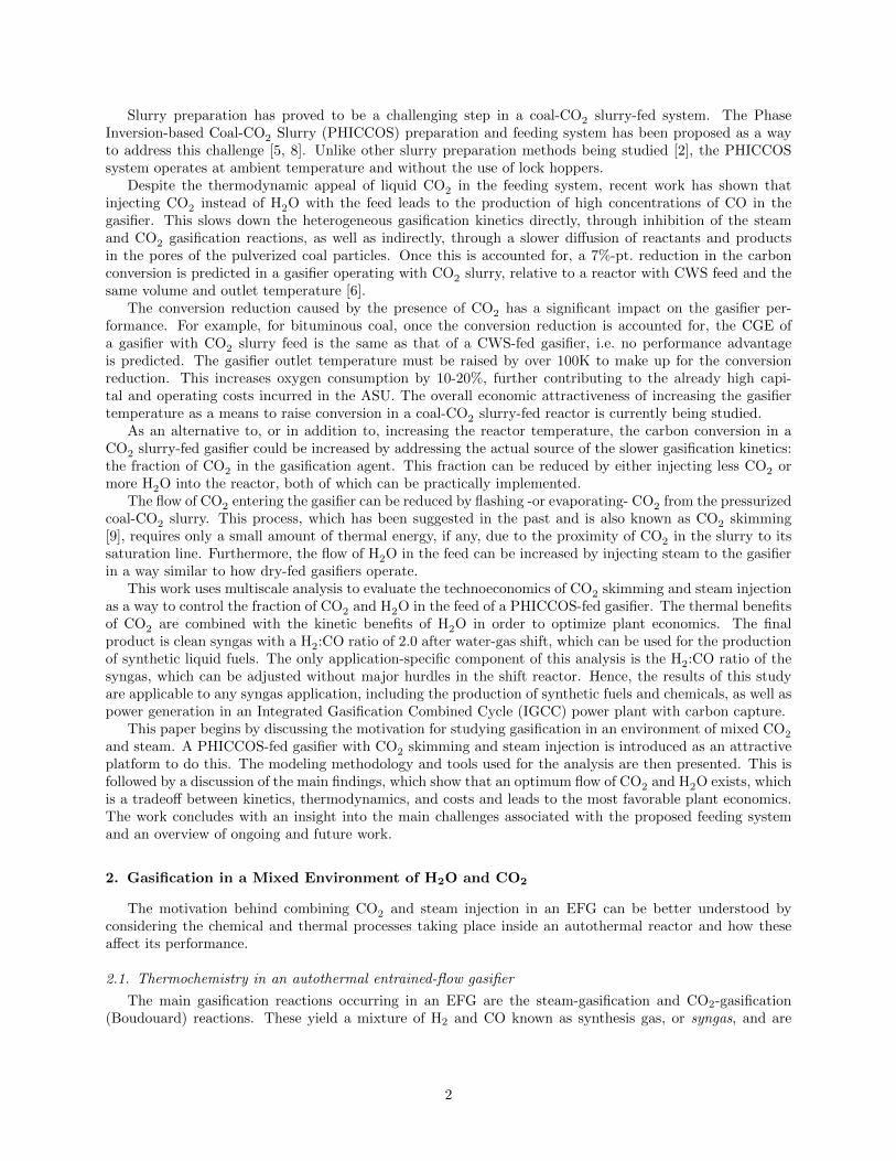
C(s) +H2O� CO +H2 +131 MJ/kmol (1)
C(s) +CO2 � 2CO +172 MJ/kmol (2)
respectively [10]. The heats of reaction are given above and the positive sign indicates that the reactions areendothermic.
Oxygen is required in the gasifier for oxidation reactions such as [10]
C(s) + 12O2 → CO −111 MJ/kmol (3)
CO + 12O2 → CO2 −283 MJ/kmol (4)
H2 + 12O2 → H2O −242 MJ/kmol. (5)
These exothermic reactions enable the reactor to operate at autothermal conditions by providing the energynecessary a) for the endothermic pyrolysis and gasification reactions, b) to heat up the reactants, and c) tomake up for any heat losses to the environment. This is schematically illustratred in Figure 1.
Figure 1: Schematic of autothermal operation of an oxygen-blown, entrained flow coal gasifier.
2.2. Quantifying gasifier performance
The cold gas e�ciency is the most commonly used measure of gasifier performance. It is defined as thefraction of the feedstock’s chemical energy that is recovered in the cooled gaseous product. It is calculatedfrom the heating value and mass flow (m) of the gasifier feed and product gas streams, according to:
CGE = (mgas) (HHV gas)(mfeed) (HHV feed) , (6)
where a higher heating value (HHV) basis has been used.The CGE has a thermal and a kinetic component. The thermal component is an indication of how
energy-intensive the reactor is, i.e. how much feedstock must be oxidized -rather than gasified- in order tomaintain autothermal operation. In eq. (6), the thermal performance is contained in the heating value ofthe gas, since oxidation products have a negligible heating value.
Feedstock heating is a major loss of thermal performance in an EFG. This is especially problematic forgasifiers with CWS feed due to the high heat capacity and vaporization enthalpy of H2O. The potentialfor better thermal performance in a reactor with coal-CO2 slurry feed has been the main motivation forconducting research in this field [4]. Beyond making the gasifier more e�cient, a good thermal performance
3
implies that less oxygen is consumed for reactions (3)-(5), reducing the high capital and operating costs ofthe air separation unit.
The kinetic gasifier performance is a measure of how fast the chemical reactions are. It can be quantifiedthrough the fraction of carbon that was converted to gas, also known as carbon conversion, and is containedin mgas in eq. (6).
Note that just like the HHV of the produced gas is not a direct indication of carbon conversion, thelatter says nothing about the characteristics of the product: a carbon conversion of 100% could mean thatthe entire feedstock has been oxidized to CO2, producing a gas with no heating value. Hence, neither thethermal performance alone nor the kinetic performance alone is su�cient to characterize gasifier operation.The CGE includes both components and is hence a much more attractive performance measure than carbonconversion or syngas heating value alone.
2.3. Optimizing the fraction of H2O and CO2 in the feed
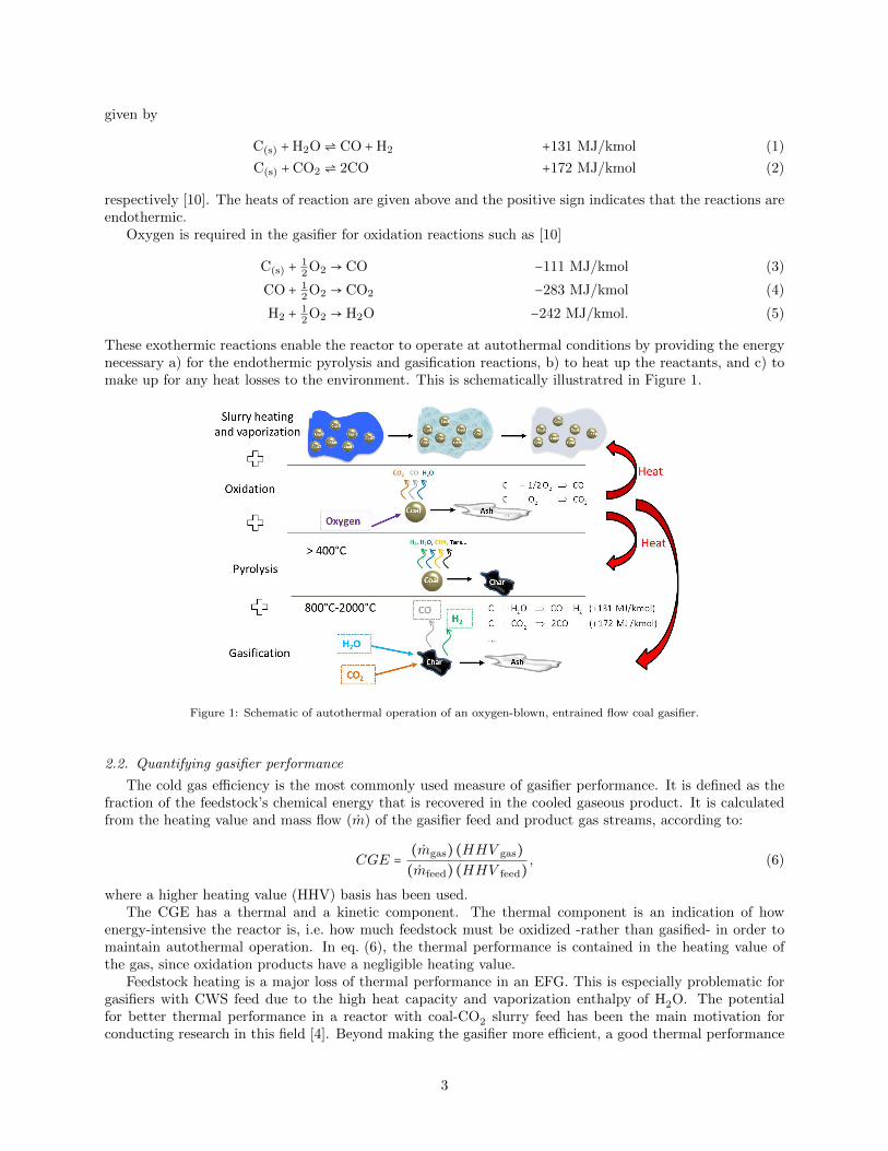
In view of the thermal advantages of CO2 as slurrying medium and of the kinetic advantages of H2Oas a gasification agent it is desirable to combine these two in order to optimize gasifier performance andeconomics. This is schematically illustrated in Figure 2, which shows qualitative gasifier performance trendsbased on preliminary calculations. For a given total flow of gasification agent (CO2+H2O), extreme casesof gasification only with steam and only with CO2 are shown, as well as intermediate cases in which bothsteam and CO2 are injected.
Figure 2: Qualitative performance and cost trends as a function of the gasification agent composition
The figure shows that a gasifier with CO2 as the sole gasification agent has low O2 consumption butalso low carbon conversion. On the other hand, a steam-injected gasifier with no CO2 injection convertsmore of the coal’s carbon content to gas but at the cost of a higher oxygen demand. Overall, the gasifierperformance can be optimized by combining steam injection and CO2 injection to achieve the best tradeo↵between oxygen consumption and conversion, i.e. a maximum gasifier cold gas e�ciency. This e�ciencyoptimum may or may not coincide with the economic optimum. Given the high cost of producing pure O2,the latter is likely to lie to the left of the performance optimum, as the figure shows, where the CGE is lowerbut so is the oxygen consumption.
2.4. PHICCOS feed with CO2 skimming and steam injection
The injection of CO2 and steam into a pressurized EFG can be implemented regardless of the charac-teristics of the reactor and feeding system. Nonetheless, CO2 slurry-fed reactors are an especially appealingplatform: CO2 is inherently contained in the feed and can be combined with steam injection to operate thegasifier at the optimum conditions in Figure 2.
The PHICCOS feeding system has been proposed as a way to feed coal to a high-pressure entrainedflow gasifier by using liquid CO2 instead of water. Unlike other proposed coal-CO2 slurry feeding systems,PHICCOS has the unique advantage that the slurry is prepared at ambient temperature and without theuse of lock hoppers. This can be achieved by using CWS as an intermediate and by taking advantage of thesurface properties of coal, as it has been described in more detail elsewhere [5, 8].
4
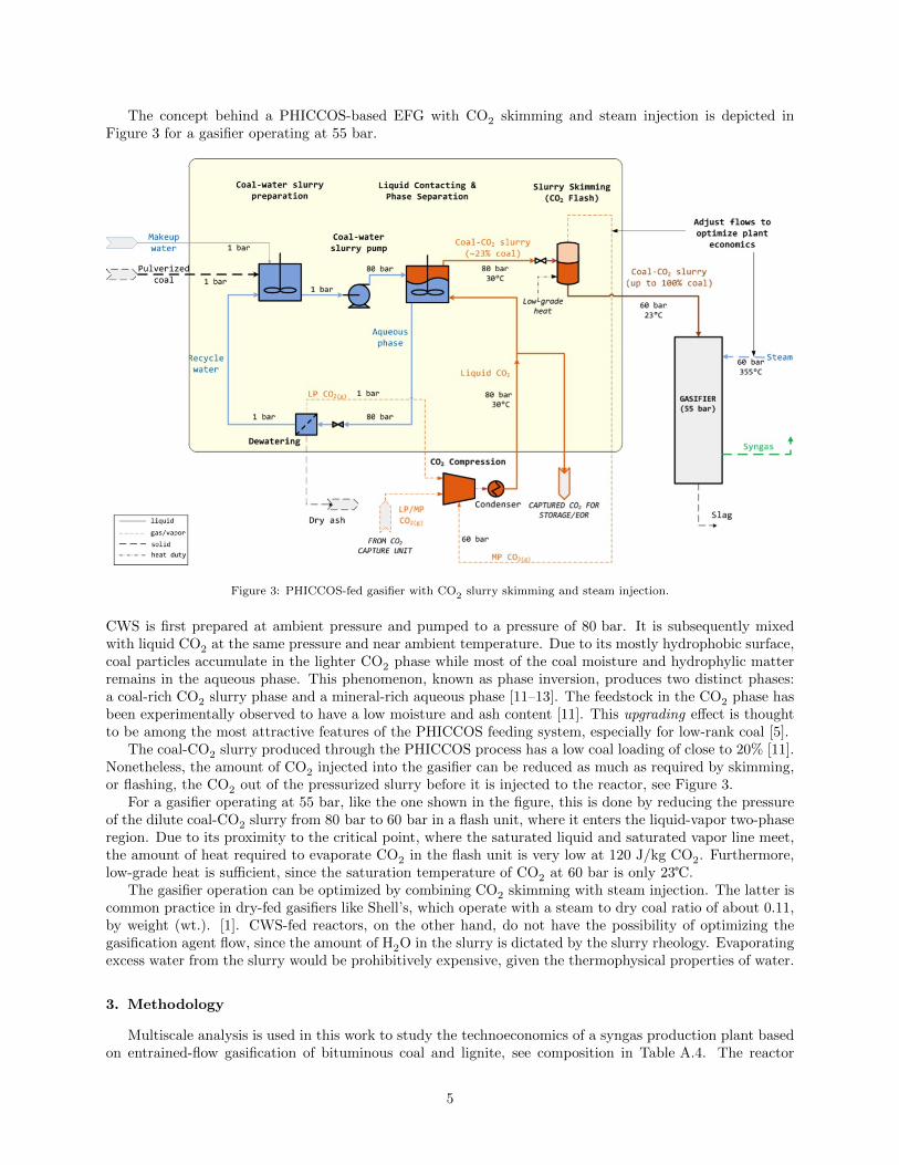
The concept behind a PHICCOS-based EFG with CO2 skimming and steam injection is depicted inFigure 3 for a gasifier operating at 55 bar.
Figure 3: PHICCOS-fed gasifier with CO2 slurry skimming and steam injection.
CWS is first prepared at ambient pressure and pumped to a pressure of 80 bar. It is subsequently mixedwith liquid CO2 at the same pressure and near ambient temperature. Due to its mostly hydrophobic surface,coal particles accumulate in the lighter CO2 phase while most of the coal moisture and hydrophylic matterremains in the aqueous phase. This phenomenon, known as phase inversion, produces two distinct phases:a coal-rich CO2 slurry phase and a mineral-rich aqueous phase [11–13]. The feedstock in the CO2 phase hasbeen experimentally observed to have a low moisture and ash content [11]. This upgrading e↵ect is thoughtto be among the most attractive features of the PHICCOS feeding system, especially for low-rank coal [5].
The coal-CO2 slurry produced through the PHICCOS process has a low coal loading of close to 20% [11].Nonetheless, the amount of CO2 injected into the gasifier can be reduced as much as required by skimming,or flashing, the CO2 out of the pressurized slurry before it is injected to the reactor, see Figure 3.
For a gasifier operating at 55 bar, like the one shown in the figure, this is done by reducing the pressureof the dilute coal-CO2 slurry from 80 bar to 60 bar in a flash unit, where it enters the liquid-vapor two-phaseregion. Due to its proximity to the critical point, where the saturated liquid and saturated vapor line meet,the amount of heat required to evaporate CO2 in the flash unit is very low at 120 J/kg CO2. Furthermore,low-grade heat is su�cient, since the saturation temperature of CO2 at 60 bar is only 23�.
The gasifier operation can be optimized by combining CO2 skimming with steam injection. The latter iscommon practice in dry-fed gasifiers like Shell’s, which operate with a steam to dry coal ratio of about 0.11,by weight (wt.). [1]. CWS-fed reactors, on the other hand, do not have the possibility of optimizing thegasification agent flow, since the amount of H2O in the slurry is dictated by the slurry rheology. Evaporatingexcess water from the slurry would be prohibitively expensive, given the thermophysical properties of water.
3. Methodology
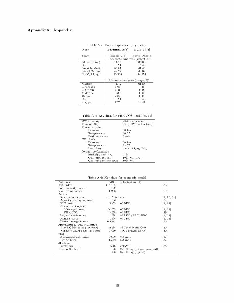
Multiscale analysis is used in this work to study the technoeconomics of a syngas production plant basedon entrained-flow gasification of bituminous coal and lignite, see composition in Table A.4. The reactor
5

considered operates with PHICCOS feed, CO2 skimming, and steam injection. The degree of CO2 skimmingand steam injection are optimized to yield the minimum syngas production costs.
The scope of the plant considered is schematically illustrated in Figure 4. The plant produces cleansyngas, made primarily of H2 and CO, and includes the coal handling and feeding system, the gasifier, andthe main syngas processing units.
Figure 4: Scope of syngas production plant considered and summary of tools used for the analysis. Coal preparation andhandling, ash handling, and Claus unit were not modeled but are included in the cost model.
Coal-CO2 slurry is prepared at 80 bar with the PHICCOS system and concentrated in a flash unit beforebeing introduced into a steam-injected gasifier operating at 55 bar. The raw syngas produced in the gasifieris saturated with water in a full-quench (FQ) cooler, leaving at a temperature of 225�. Its H2:CO ratio isthen adjusted in a water-gas shift (WGS) reactor. The target H2:CO ratio for the shifted syngas dependson the application. A ratio of 2.0 was assumed here, which is close to that required for the production ofsynthetic liquid fuels.
The shifted syngas is brought to 40� and hereby freed of the majority of its H2O content, which leavesthe cooler as condensate. The cool syngas enters an acid gas removal (AGR) unit, where the majority of itsCO2 and H2S content is separated. The clean, pressurized syngas leaving the AGR is the final product. It hasa pressure of about 50 bar, consists of mainly CO and H2 and, with minor modification in the WGS reactoroperation, can be used for any application requiring syngas, e.g. a Fischer-Tropsh process for synthetic liquidfuel production, an IGCC plant, methanol synthesis, etc.
The modeling approach and tools used are also indicated in Figure 4. Except for the gasifier, all processunits are modeled as 0-D components using Microsoft Excel [14] and Aspen Properties Excel Calculator[15]. For the gasifier, a detailed, 1-D reduced order model is used, which includes a high-pressure chemicalkinetics submodel and is capable of predicting carbon conversion. The gasifier ROM is implemented in AspenCustom Modeler (ACM) [16] and is linked to Excel through Aspen Simulation Workbook (ASW) [17].
The economics of the plant are assessed with a cost model, also in Excel, that uses the performanceand equipment size from the simulation results as an input. The economic figure of merit is the syngasproduction cost per mole of exported syngas.
The cost model is used to find the optimum flow and composition of the gasification agent fed to thereactor, i.e. that leading to a minimum syngas production cost. The optimizer and tools in the Excel-basedsoftware Crystal Ball (CB) [18] are used for this purpose. The latter is linked to ASW through Visual Basicfor Applications (VBA) [19].
6
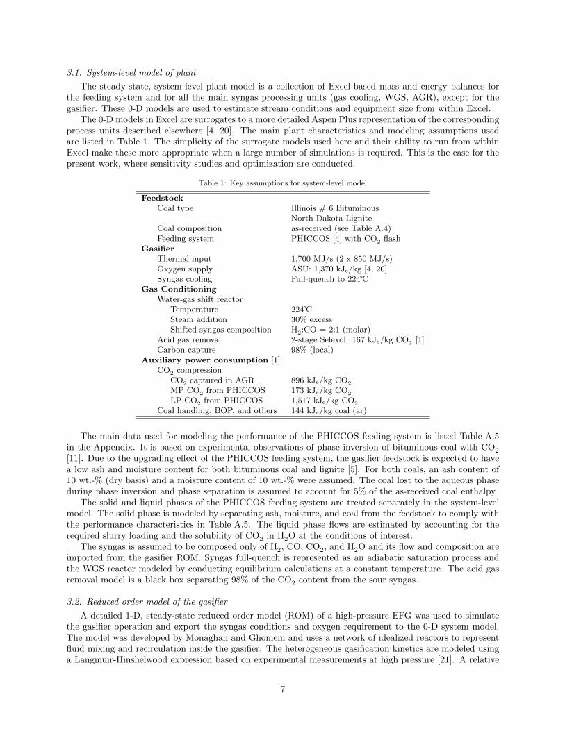
3.1. System-level model of plant
The steady-state, system-level plant model is a collection of Excel-based mass and energy balances forthe feeding system and for all the main syngas processing units (gas cooling, WGS, AGR), except for thegasifier. These 0-D models are used to estimate stream conditions and equipment size from within Excel.
The 0-D models in Excel are surrogates to a more detailed Aspen Plus representation of the correspondingprocess units described elsewhere [4, 20]. The main plant characteristics and modeling assumptions usedare listed in Table 1. The simplicity of the surrogate models used here and their ability to run from withinExcel make these more appropriate when a large number of simulations is required. This is the case for thepresent work, where sensitivity studies and optimization are conducted.
Table 1: Key assumptions for system-level model
Feedstock
Coal type Illinois # 6 BituminousNorth Dakota Lignite
Coal composition as-received (see Table A.4)Feeding system PHICCOS [4] with CO2 flash
Gasifier
Thermal input 1,700 MJ/s (2 x 850 MJ/s)Oxygen supply ASU: 1,370 kJe/kg [4, 20]Syngas cooling Full-quench to 224�
Gas Conditioning
Water-gas shift reactorTemperature 224�Steam addition 30% excessShifted syngas composition H2:CO = 2:1 (molar)
Acid gas removal 2-stage Selexol: 167 kJe/kg CO2 [1]Carbon capture 98% (local)
Auxiliary power consumption [1]CO2 compression
CO2 captured in AGR 896 kJe/kg CO2
MP CO2 from PHICCOS 173 kJe/kg CO2
LP CO2 from PHICCOS 1,517 kJe/kg CO2
Coal handling, BOP, and others 144 kJe/kg coal (ar)
The main data used for modeling the performance of the PHICCOS feeding system is listed Table A.5in the Appendix. It is based on experimental observations of phase inversion of bituminous coal with CO2
[11]. Due to the upgrading e↵ect of the PHICCOS feeding system, the gasifier feedstock is expected to havea low ash and moisture content for both bituminous coal and lignite [5]. For both coals, an ash content of10 wt.-% (dry basis) and a moisture content of 10 wt.-% were assumed. The coal lost to the aqueous phaseduring phase inversion and phase separation is assumed to account for 5% of the as-received coal enthalpy.
The solid and liquid phases of the PHICCOS feeding system are treated separately in the system-levelmodel. The solid phase is modeled by separating ash, moisture, and coal from the feedstock to comply withthe performance characteristics in Table A.5. The liquid phase flows are estimated by accounting for therequired slurry loading and the solubility of CO2 in H2O at the conditions of interest.
The syngas is assumed to be composed only of H2, CO, CO2, and H2O and its flow and composition areimported from the gasifier ROM. Syngas full-quench is represented as an adiabatic saturation process andthe WGS reactor modeled by conducting equilibrium calculations at a constant temperature. The acid gasremoval model is a black box separating 98% of the CO2 content from the sour syngas.
3.2. Reduced order model of the gasifier
A detailed 1-D, steady-state reduced order model (ROM) of a high-pressure EFG was used to simulatethe gasifier operation and export the syngas conditions and oxygen requirement to the 0-D system model.The model was developed by Monaghan and Ghoniem and uses a network of idealized reactors to representfluid mixing and recirculation inside the gasifier. The heterogeneous gasification kinetics are modeled usinga Langmuir-Hinshelwood expression based on experimental measurements at high pressure [21]. A relative
7
reactivity factor ( ) is used to account for reactivity di↵erences between coals of di↵erent ranks. Internalmass transfer limitations at high temperatures are accounted for through the e↵ectiveness factor approach.The ROM [22–25] and its high-pressure kinetic submodel [6] have been described in detail elsewhere.
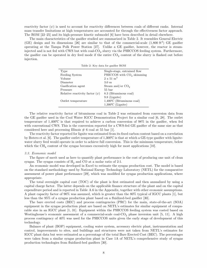
The main characteristics of the gasifier studied are summarized in Table 2. It resembles General Electric(GE) design and its dimensions [26] are similar to that of the commercial-scale (1,800 ft3) GE gasifieroperating at the Tampa Polk Power Station [27]. Unlike a GE gasifier, however, the reactor is steam-injected and is not fed with CWS but with coal-CO2 slurry via the PHICCOS feeding system. Furthermore,the gasifier can be operated in dry feed mode if the entire CO2 content of the slurry is flashed out beforeinjection.
Table 2: Key data for gasifier ROM
Type Single-stage, entrained flowFeeding System PHICCOS with CO2 skimmingVolume 2 x 51 m3
Diameter 3.0 mGasification agent Steam and/or CO2
Pressure 55 barRelative reactivity factor ( ) 8.3 (Bituminous coal)
9.8 (Lignite)Outlet temperature 1,400� (Bituminous coal)
1,300� (Lignite)
The relative reactivity factor of bituminous coal in Table 2 was estimated from conversion data fromthe GE gasifier used in the Cool Water IGCC Demonstration Project for a similar coal [6, 28]. The outlettemperature of 1,400� is that required to achieve a carbon conversion of 98% in the gasifier, when fedwith conventional CWS. This is the conversion reported for a CWS-fed GE gasifier of the same size as thatconsidered here and processing Illinois # 6 coal at 55 bar [1].
The reactivity factor reported for lignite was estimated from its fixed carbon content based on a correlationby Botero et al. [6]. The gasifier outlet temperature of 1,300� is that at which a GE-type gasifier with lignite-water slurry feed would operate in order to achieve full conversion. This is the minimum temperature, belowwhich the CH4 content of the syngas becomes excessively high for most applications [10].
3.3. Economic modelThe figure of merit used as here to quantify plant performance is the cost of producing one unit of clean
syngas. The syngas consists of H2 and CO at a molar ratio of 2:1.An economic model was developed in Excel to estimate the syngas production cost. The model is based
on the standard methodology used by National Energy Technology Laboratory (NETL) for the comparativeassessment of power plant performance [29], which was modified for syngas production applications, whereappropriate.
The total overnight capital cost (TOC) of the plant is first estimated and then annualized by using acapital charge factor. The latter depends on the applicable finance structure of the plant and on the capitalexpenditure period and is reported in Table A.6 in the Appendix, together with other economic assumptions.A plant capacity factor of 90% was assumed, which is greater than the 80% typical of IGCC plants [1], butless than the 95% of a syngas production plant based on a fluidized-bed gasifier [30].
The bare erected costs (BEC) and process contingencies (PRC) for the main, state-of-the-art (SOA)equipment in the syngas production plant are based on NETL’s estimates for similar equipment of compa-rable size in an IGCC plant [1, 31]. Equipment within the PHICCOS feeding system was costed based onWestinghouse’s economic assessment of a commercial-scale coal-CO2 phase inversion unit [5, 11]. A highprocess contingency of 40% was used for the PHICCOS units given the early stage of development of thistechnology.
Balance of plant (BOP) equipment, cooling water system, accessory electric plant, instrumentation andcontrol, improvements to sites, and buildings and structures were not taken from NETL’s estimates forIGCC plant data but were estimated as a percentage of the total Bare Erected Cost (BEC). The percentageswere taken from a similar syngas production plant in Case 1A of NETL’s comprehensive study of syngasproduction technologies from fluidized-bed gasifiers [30].
8
The latter source was also used for estimating operating and maintenance (O&M) costs in the plant,excluding electricity as well as oxygen and nitrogen purchase costs. These gases are produced in the plant’sASU.
Steam and electricity are assumed to be imported rather than produced locally. Process integration isnot considered. The fuel value of steam was used to calculate the cost of steam in Table A.6, assuming aboiler e�ciency of 90% [32].
Finally, the Chemical Engineering Plant Cost Index (CEPCI) [33] was used to convert all equipmentcosts to 2011 U.S. dollars, where necessary. Furthermore, the six-tenths factor rule [34] was used to scale allreference BECs for the individual pieces of equipment to the capacity predicted by the simulations.
3.4. Cases studied
The e↵ectiveness of steam injection and CO2 skimming are assessed here as a means to overcome thelow conversion in a slurry-fed gasifier with PHICCOS feed, when compared to one with CWS feed. Bothbituminous coal and lignite were studied in order to cover a broad range of coal ranks.
A gasifier with CWS feed was used as a reference to set the gasifier temperature at a fixed value. Thelatter was left unchanged during the analysis in order to isolate the e↵ects of CO2 and steam injection.Hence, the gasifier operates at a constant outlet temperature of 1,400� for bituminous coal feed and 1,300�for lignite. The e↵ect of temperature on conversion in a gasifier with coal-CO2 slurry feed has been reportedelsewhere [6] and is currently being studied when in conjunction with CO2 skimming and steam injection.
The moisture and ash content of the feedstock delivered by the PHICCOS feeding system to the gasifieris expected to be the same for both coals, see Table A.5. The main di↵erence between the two feedstocks isthus in their fixed carbon and oxygen content, as well as in the temperature at which they are gasified.
4. Results and Discussion
This section presents and discusses the e↵ect of CO2 slurry skimming (i.e. of di↵erent slurry loadings) andof H2O injection on the performance and economics of a syngas production plant with a PHICCOS-basedgasifier operating on bituminous coal or lignite. The gasifier outlet temperature is constant and correspondsto that of a CWS-fed gasifier with the same feedstock.
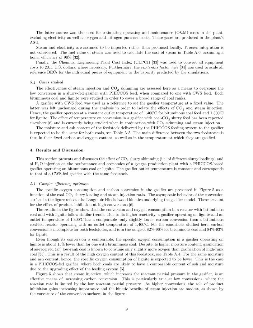
4.1. Gasifier e�ciency optimum
The specific oxygen consumption and carbon conversion in the gasifier are presented in Figure 5 as afunction of the coal-CO2 slurry loading and steam injection ratio. The asymptotic behavior of the conversionsurface in the figure reflects the Langmuir-Hinshelwood kinetics underlying the gasifier model. These accountfor the e↵ect of product inhibition at high conversions [6].
The results in the figure show that the conversion and oxygen consumption in a reactor with bituminouscoal and with lignite follow similar trends. Due to its higher reactivity, a gasifier operating on lignite and anoutlet temperature of 1,300� has a comparable -only slightly lower- carbon conversion than a bituminouscoal-fed reactor operating with an outlet temperature of 1,400�. For the conditions studied here, carbonconversion is incomplete for both feedstocks, and is in the range of 82%-96% for bituminous coal and 84%-93%for lignite.
Even though its conversion is comparable, the specific oxygen consumption in a gasifier operating onlignite is about 15% lower than for one with bituminous coal. Despite its higher moisture content, gasificationof as-received (ar) low-rank coal is known to consume only slightly more oxygen than gasification of high-rankcoal [35]. This is a result of the high oxygen content of this feedstock, see Table A.4. For the same moistureand ash content, hence, the specific oxygen consumption of lignite is expected to be lower. This is the casein a PHICCOS-fed gasifier, where both coals are likely to have a comparable content of ash and moisturedue to the upgrading e↵ect of the feeding system [5].
Figure 5 shows that steam injection, which increases the reactant partial pressure in the gasifier, is ane↵ective means of increasing carbon conversion. This is particularly true at low conversions, where thereaction rate is limited by the low reactant partial pressure. At higher conversions, the role of productinhibition gains increasing importance and the kinetic benefits of steam injection are modest, as shown bythe curvature of the conversion surfaces in the figure.
9
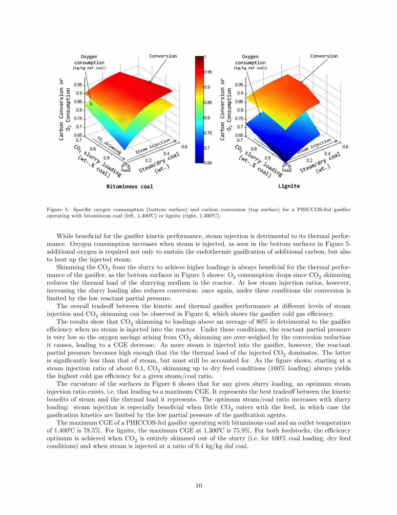
Figure 5: Specific oxygen consumption (bottom surface) and carbon conversion (top surface) for a PHICCOS-fed gasifieroperating with bituminous coal (left, 1,400�) or lignite (right, 1,300�).
While beneficial for the gasifier kinetic performance, steam injection is detrimental to its thermal perfor-mance. Oxygen consumption increases when steam is injected, as seen in the bottom surfaces in Figure 5:additional oxygen is required not only to sustain the endothermic gasification of additional carbon, but alsoto heat up the injected steam.
Skimming the CO2 from the slurry to achieve higher loadings is always beneficial for the thermal perfor-mance of the gasifier, as the bottom surfaces in Figure 5 shows: O2 consumption drops since CO2 skimmingreduces the thermal load of the slurrying medium in the reactor. At low steam injection ratios, however,increasing the slurry loading also reduces conversion: once again, under these conditions the conversion islimited by the low reactant partial pressure.
The overall tradeo↵ between the kinetic and thermal gasifier performance at di↵erent levels of steaminjection and CO2 skimming can be observed in Figure 6, which shows the gasifier cold gas e�ciency.
The results show that CO2 skimming to loadings above an average of 80% is detrimental to the gasifiere�ciency when no steam is injected into the reactor. Under these conditions, the reactant partial pressureis very low so the oxygen savings arising from CO2 skimming are over-weighed by the conversion reductionit causes, leading to a CGE decrease. As more steam is injected into the gasifier, however, the reactantpartial pressure becomes high enough that the the thermal load of the injected CO2 dominates. The latteris significantly less than that of steam, but must still be accounted for. As the figure shows, starting at asteam injection ratio of about 0.1, CO2 skimming up to dry feed conditions (100% loading) always yieldsthe highest cold gas e�ciency for a given steam/coal ratio.
The curvature of the surfaces in Figure 6 shows that for any given slurry loading, an optimum steaminjection ratio exists, i.e. that leading to a maximum CGE. It represents the best tradeo↵ between the kineticbenefits of steam and the thermal load it represents. The optimum steam/coal ratio increases with slurryloading: steam injection is especially beneficial when little CO2 enters with the feed, in which case thegasification kinetics are limited by the low partial pressure of the gasification agents.
The maximum CGE of a PHICCOS-fed gasifier operating with bituminous coal and an outlet temperatureof 1,400� is 78.5%. For lignite, the maximum CGE at 1,300� is 75.9%. For both feedstocks, the e�ciencyoptimum is achieved when CO2 is entirely skimmed out of the slurry (i.e. for 100% coal loading, dry feedconditions) and when steam is injected at a ratio of 0.4 kg/kg daf coal.
10
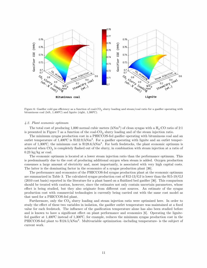
Figure 6: Gasifier cold gas e�ciency as a function of coal-CO2 slurry loading and steam/coal ratio for a gasifier operating withbituminous coal (left, 1,400�) and lignite (right, 1,300�).
4.2. Plant economic optimum
The total cost of producing 1,000 normal cubic meters (kNm3) of clean syngas with a H2:CO ratio of 2:1is presented in Figure 7 as a function of the coal-CO2 slurry loading and of the steam injection ratio.
The minimum syngas production cost in a PHICCOS-fed gasifier operating with bituminous coal and anoutlet temperature of 1,400� is $132.9/kNm3. For a gasifier operating with lignite and an outlet temper-ature of 1,300�, the minimum cost is $128.6/kNm3. For both feedstocks, the plant economic optimum isachieved when CO2 is completely flashed out of the slurry, in combination with steam injection at a ratio of0.23 kg/kg ar coal.
The economic optimum is located at a lower steam injection ratio than the performance optimum. Thisis predominantly due to the cost of producing additional oxygen when steam is added. Oxygen productionconsumes a large amount of electricity and, most importantly, is associated with very high capital costs.The latter is the dominating factor in the economics of a syngas production plant [36].
The performance and economics of the PHICCOS-fed syngas production plant at the economic optimumare summarized in Table 3. The calculated syngas production cost of $12-13/GJ is lower than the $15-19/GJ(2010 cost basis) reported in the literature for a plant based on a fluidized bed gasifier [36]. This comparisonshould be treated with caution, however, since the estimates not only contain uncertain parameters, whosee↵ect is being studied, but they also originate from di↵erent cost sources. An estimate of the syngasproduction cost with commercial technologies is currently being carried out with the same cost model asthat used for a PHICCOS-fed plant.
Furthermore, only the CO2 slurry loading and steam injection ratio were optimized here. In order tostudy the e↵ect of these two variables in isolation, the gasifier outlet temperature was maintained at a fixedvalue for each feedstock. The influence of the gasification temperature alone has also been studied beforeand is known to have a significant e↵ect on plant performance and economics [6]. Operating the lignite-fed gasifier at 1,400� instead of 1,300�, for example, reduces the minimum syngas production cost in thePHICCOS-fed plant to $124.5/kNm3. Multivariable optimization -including temperature- is the subject ofcurrent work.
11
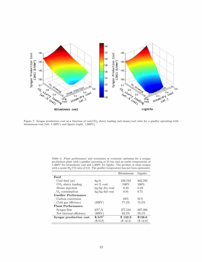
Figure 7: Syngas production cost as a function of coal-CO2 slurry loading and steam/coal ratio for a gasifier operating withbituminous coal (left, 1,400�) and lignite (right, 1,300�).
Table 3: Plant performance and economics at economic optimum for a syngasproduction plant with a gasifier operating at 55 bar and an outlet temperature of1,400� for bituminous coal and 1,300� for lignite. The product is clean syngaswith a molar H2:CO ratio of 2.0. The gasifier temperature has not been optimized.
Bituminous LigniteFeed
Coal feed (ar) kg/h 238,783 402,705CO2 slurry loading wt.% coal 100% 100%Steam injection kg/kg dry coal 0.23 0.23O2 consumption kg/kg daf coal 0.81 0.71
Gasifier Performance
Carbon conversion 93% 91%Cold gas e�ciency (HHV) 77.4% 75.5%
Plant Performance
Syngas flow kN3/h 377,516 367,466Net thermal e�ciency (HHV) 62.5% 59.1%
Syngas production cost $/kN3 $ 132.9 $128.6($/GJ) ($ 12.4) ($ 12.0)
12
5. Conclusions and Outlook
The Phase Inversion-based Coal-CO2 Slurry (PHICCOS) feeding system has been suggested as a moree�cient alternative to conventional coal-water slurry feed in gasification-based plants with carbon capture.While coal-CO2 slurry has significant thermal advantages, a lower carbon conversion is expected in anenvironment with a high ratio of CO2:H2O in the feed.
Multiscale analysis was used to study CO2 skimming and steam injection as a way to control the flow ofCO2 and H2O injected into a PHICCOS-fed gasifier and improve carbon conversion. Both bituminous coaland lignite feedstocks were considered within the scope of a gasification-based plant producing clean syngaswith a H2:CO ratio of 2.0.
The optimum gasifier e�ciency was found to be a tradeo↵ between the gasification kinetics and thethermal load associated with the injection of the gasification agents H2O and CO2. A maximum gasifiercold gas e�ciency is achieved when the CO2 content of the slurry is flashed completely to yield a dry feed,in combination with steam injection at a ratio of 0.4 kg per kg of coal (dry basis).
For a fixed gasifier temperature of 1,400� for bituminous coal and 1,300� for lignite, the minimumsyngas production cost in the plant is $132.9/kNm3 and $128.6/kNm3, respectively. The plant economicoptimum is achieved at a steam injection ratio of 0.23 kg per kg of dry coal.
The optima unveiled in this study do not consider the influence of gasification temperature, which hasbeen studied in isolation before and is known to have a significant e↵ect on plant technoeconomics. Futurework will conduct multivariable optimization in order to include this in the analysis, together with the e↵ectof other important operating and design variables and of their uncertainty. Furthermore, a comparisonwith commerical syngas production technologies will be carried out and the potential practical challengesassociated with the transport of a nearly dry solid from the CO2 skimming vessel to the gasifier of aPHICCOS-fed system with full skimming will be addressed.
Acknowledgments
The authors would like to acknowledge BP for the financial support and Aspen Technology, Inc. for thesimulation software.
References
[1] National Energy Technology Laboratory , Cost and performance baseline for fossil energy plants, revision 2, TechnicalReport DOE/NETL-2010/1397 (2010).
[2] Dooher J., Marasigan J., Goldstein H. N., Liquid CO2 slurry (LCO2) for feeding low rank coal (LRC) to gasifiers, in: 37thInternational Technical Conference on Clean Coal and Fuel Systems, Clearwater, FL (USA), 2012.
[3] Dooher J. P., Castaldi M. J., Rubin D., Phillips J. N., Scho↵ R., Evaluation of low rank coal/liquid CO2 slurries forgeneric, single-stage, slurry-fed gasifiers, in: 35th International Technical Conference of Coal Utilization and Fuel Systems,Clearwater, Florida (USA), 2010.
[4] Botero C., Field R. P., Herzog H., Ghoniem A. F., Performance of an IGCC plant with carbon capture and coal-CO2-slurryfeed: Impact of coal rank, slurry loading, and syngas cooling technology, Industrial & Engineering Chemistry Research51 (36) (2012) 11778–11790.
[5] Botero C., Field R., Herzog H., Ghoniem A., Coal-CO2 slurry feed for pressurized gasifiers: Slurry preparation systemcharacterization and economics, in: Greenhouse Gas Technologies Conference (GHGT-11), Kyoto, Japan, 2012.
[6] Botero C., Field R. P., Herzog H. J., Ghoniem A. F., Impact of finite-rate kinetics on carbon conversion in a high-pressure,single-stage entrained flow gasifier with coal-CO2 slurry feed, Applied Energy 104 (0) (2013) 408–417.
[7] Black & Veatch , Holcomb generation expansion project: Coal technology selection study, Technical Report 144102 (2006).
[8] Botero C., Field R., Herzog H., Ghoniem A., Method for preparing a slurry of pulverized solid material in liquid orsupercritical carbon dioxide, U.S. Patent Application No.: 61/712954 (2012).
[9] McNamee G. P., White G. A., Use of lignite in texaco gasification-based-combined-cycle power plants, Technical ReportAP-4509, Prepared by Energy Conversion Systems, Inc. for Electric Power Research Institute (1986).
[10] Higman C., van der Burgt M., Gasification, 2nd Edition, Elsevier, 2008.
13
[11] Westinghouse Electric Corporation , Development of the LICADO coal cleaning process, Technical Report DOE/PC/79873-T1; (1990).
[12] Cooper M., Muenchow H. O., Chiang S. H., Klinzing G. E., Morsi S., Venkatadri R., The licado coal cleaning process: Astrategy for reducing SO2 emissions from fossil-fueled power plants, in: Energy Conversion Engineering Conference, 1990.IECEC-90. Proceedings of the 25th Intersociety, Vol. 4, 1990, pp. 137–142.
[13] Chi S. M., Interfacial properties and coal cleaning in the licado process, Ph.D. thesis, University of Pittsburgh (1986).
[14] Microsoft Corporation , Microsoft Excel 2010 (2010).
[15] Aspen Technology, Inc. , Aspen Properties Excel Calculator, Version 7.3 (2011).
[16] Aspen Technology, Inc. , Aspen Custom Modeler, Version 7.3 (2011).
[17] Aspen Technology, Inc. , Aspen Simulation Workbook, Version 7.3 (2011).
[18] Oracle , Oracle Crystal Ball Clasroom Edition, Release 11.1.2.2.000 (2012).
[19] Microsoft Corporation , Microsoft Visual Basic for Applications, Version 7.0 (2010).
[20] Field R. P., Brasington R., Baseline flowsheet model for IGCC with carbon capture, Industrial & Engineering ChemistryResearch 50 (19) (2011) 11306–11312.
[21] Muehlen H. J., van Heek K. H., Juentgen H., Kinetic studies of steam gasification of char in the presence of H2, CO2 andCO, Fuel 64 (7) (1985) 944–949.
[22] Monaghan R. F. D., Ghoniem A. F., A dynamic reduced order model for simulating entrained flow gasifiers: Part I: Modeldevelopment and description, Fuel 91 (1) (2012) 61–80.
[23] Monaghan R. F. D., Ghoniem A. F., A dynamic reduced order model for simulating entrained flow gasifiers. part ii: Modelvalidation and sensitivity analysis, Fuel 94 (0) (2012) 280–297.
[24] Monaghan R. F. D., Ghoniem A. F., Simulation of a commercial-scale entrained flow gasifier using a dynamic reducedorder model, Energy & Fuels 26 (2) (2011) 1089–1106.
[25] Monaghan R. F. D., Dynamic reduced order modeling of entrained flow gasifiers, Phd thesis, Massachusetts Institute ofTechnology (2010).
[26] Chinese Academy of Sciences (CAS) and U.S. Department of Energy (DOE) , The United States of America and the People’sRepublic of China experts report on integrated gasification combined cycle technology, Technical Report DOE/FE-0357(1996).
[27] Mc.Daniel J. E., Tampa Electric Polk Power Station Integrated Gasification Combined Cycle Project, Technical report,Prepared by Tampa Electric Company for The U.S. Department of Energy (2002).
[28] Electric Power Research Institute , Cool Water coal gasification program: Final report, Technical Report GS-6805 (1990).
[29] U.S. Department of Energy, National Energy Technology Laboratory (NETL) , Quality guidelines for energy system studies:Cost estimation methodology for NETL assessments of power plant performance, Technical Report DOE/NETL-2011/1455,NETL (2011).
[30] U.S. Department of Energy, National Energy Technology Laboratory (NETL) , Industrial size gasification for syngas,substitute natural gas and power production, Technical Report DOE/NETL-401/040607, U.S. Department of Energy,National Energy Technology Laboratory (2007).
[31] U.S. Department of Energy, National Energy Technology Laboratory (NETL) , Cost and performance baseline for fossilenergy plants, volume 3a: Low rank coal to electricity: Igcc cases, Technical report, U.S. Department of Energy, NationalEnergy Technology Laboratory (NETL).
[32] U.S. Department of Energy , Energy E�ciency and Renewable Energy, Advanced Manufacturing O�ce: benchmark thefuel cost of steam generation (2012).
[33] Lozowski D., Economic indicators, Chemical Engineering 120 (1) (2013) 63–64.
[34] Peters M., Timmerhaus K., West R., Plant Design and economics for chemical engineers, 5th Edition, McGraw-Hill, 2003.
[35] Klosek J., Smith A. R., Solomon P. R., The role of oxygen in coal gasification, in: Proceedings of the Eighth AnnualIndustrial Energy Technology Conference, Houston, TX (USA), 1986.
[36] International Energy Agency , Energy Technology Systems Analysis Program, Technology Brief S01: Syngas Productionfrom Coal (2010).
[37] U.S. Energy Information Administration , Annual coal report 2011 (2012).
[38] U.S. Energy Information Administration , Electric power monthly (January 2013).
14
AppendixA. Appendix
Table A.4: Coal composition (dry basis)
Rank Bituminous[1] Lignite [31]
Seam Illinois # 6 North DakotaProximate Analyses (weight %)
Moisture (ar) 11.12 36.08Ash 10.91 15.43Volatile Matter 39.37 41.49Fixed Carbon 49.72 43.09HHV, kJ/kg 30,506 24,254
Ultimate Analyses (weight %)Carbon 71.72 61.88Hydrogen 5.06 4.29Nitrogen 1.41 0.98Chlorine 0.33 0.00Sulfur 2.82 0.98Ash 10.91 15.43Oxygen 7.75 16.44
Table A.5: Key data for PHICCOS model [5, 11]
CWS loading 20%-wt. ar coalFlow of CO2 CO2:CWS = 0.5 (wt.)Phase inversion
Pressure 80 barTemperature 30 �Residence time 5 min.
CO2 flashPressure 60 barTemperature 23 �Heat duty < 0.12 kJ/kg CO2
Overall performanceEnthalpy recovery 95%Coal product ash 10%-wt. (dry)Coal product moisture 10%-wt.
Table A.6: Key data for economic model
Cost basis 2011 U.S. Dollars ($)Cost index CEPCI [33]Plant capacity factor 0.9Levelization factor 1.268 [29]CapitalBare erected costs see Reference [1, 30, 31]Capacity scaling exponent 0.6 [34]EPC costs 9.4% of BEC [1, 31]Process contingency
SOA equipment 0-20% of BEC [1, 31]PHICCOS 40% of BEC [29]
Project contingency 16% of BEC+EPC+PRC [1, 31]Owner’s costs 23% of TPC [1, 31]Capital charge factor 0.1243 [29]
Operation & MaintenanceFixed O&M costs (1st year) 2.6% of Total Plant Cost [30]Variable O&M costs (1st year) 0.450 $/GJ syngas (HHV) [30]
FuelBituminous coal price 50.80 $/tonne [37]Lignite price 15.72 $/tonne [37]
UtilitiesElectricity 6.46 c/kWh [38]Steam (60 bar) 8.3 $/1000 kg (bituminous coal)
4.6 $/1000 kg (lignite)
15