onan cck generator manual
TRANSCRIPT
.;
FOR
onan~@CCK INDUSTRIAL ENGINE
MODELS
CCK- MS/663FCCK- MS/1070F
~CCK- MS/1244GCCK- MS/1395GCCK- MS/1400G
Postal vehicle Application I
______~—-”’”
ONAN 1400 73RD AVENUE N.E. “ MINNEAPOLIS, MINNESOTA 55432A DIVISION OF ONAN CORPORATION
927-1037 6/12/68 Printed in u.s. A
INTRODUCTION,— 1(
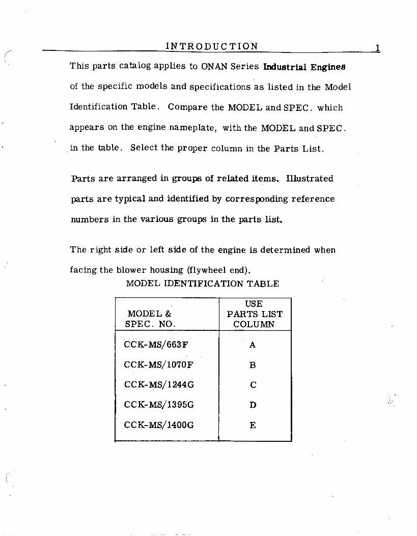
This parts Catilog applies to ONAN Series Industrtil Engines
of the specific models and specifications as listed in the Model
Identification Table. compare the MODEL and SPEC. which
appears on the engine nameplate, with the MODEL and SPE C.
in the table. Select the proper column in the Parts List.
Parts are arranged in groups of related items. Illustrated
parts are typical and identified by corresponding reference
numbers in the various groups in the parts list.
The right side or left side of the engine is determined when
facing the -- - “ ‘-- - - “blower housing (Ilywheel end).
MODEL IDENTIFICATION TABLE
USEMODE L &’ PARTS LIST
SPEC. NO. COLUMN
CCK-MS/663F A
ccK-Ms/lo70F B
CCK-MS/1244G c
ccK-Ms/1395G D
ccK-Ms/1400G E
:..-..
/

2
- T34
24
\
01.....*?,‘:
f
., ”..
t.:::,,,,
[
22{t
r–’
;
126/ \eII
II
FIG. A - CYLINDER BLOCK, OIL BASE AND
22
I
,,
5
EAR COVER GROUP
,./
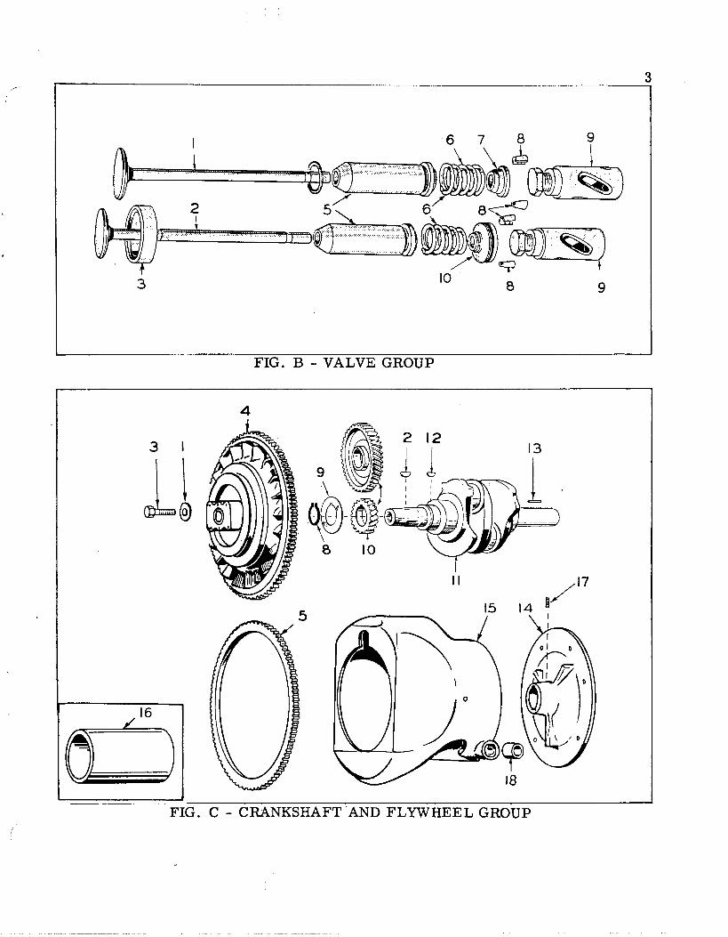
FIG . B - VALVE GROUP
31
,16
4
II
FIG. C - CRANKSHAFT AND FLWHEEL GROUP
.

4
6
FIG. D - CAMSHAFT AND GOVERNOR CUP GROUP
FIG. E - CONNECTING ROD AND PISTON GROUP

o
29
22
b S.,h. 13
-..FIG. F - FUEL SYSTEM GROUP
FIG. G - CARBURETOR PARTS GROUP

6HY
~;,,~—-”
~y..,: +&@,-.#“ , X,514 0 ‘“” 10
FIG. H - FUEL PUMP PARTS GROUP
I
14 al,
FIG. :
6
(3—
5—
- OIL PUMP GROUP
oa
. . . . .. . . .
..*40
,.,. .
. . . .
12

...
‘e- ●-m@T● /y\
-33-6
8-
15$— ,’
I 20 6
FIG. J - IGNITION GROUP

I
I
7
FIG. K - AIR HOUSING GROUP
@
0,-
9
(“
FIG . L - START MOTOR & AiTE~ATOR “GROUP

FIG . M - START MOTOR PARTS GROUP

10 PARTS LIST
REF. PARTNO. NO.
991011
11
12131313A13B141516171920222323242425252628282829293031A
31B
323334
3637
38394041424344
45
103C224103A296103B1111OA1O19
11OA1418
l“23B~9,3123A678123A129123-591123A64311OA66611OA667517-48520A114123A191102B158110A89211OD89O11OD88411OD89111OD883102E457102B55150S-56505P435505-347505-497509A40509A97516A11101K389
104A57S
101K115101C316101A367
509A41516A72
11OA445123A104526-63850-45141A78123B67511OA879
114A22
G
r—
1
1
1
11
1
122151121
1
1
1
1
22
2
112
14
5125118
0
Al
E—
1
1
1
1
1
22
5112
1
1
11
1
1
22
2
112
14
5125118
0
E—
1
1
1
1
1
22
5112
1
1
11
11
22
2
112
14
5125118
0
SIE—
1
1
1
1
1
22
5112
1
1
11
11
22
2
112
14
5125118
0
)
F—
1
11
1
1
2215112
1
1
11
1
122
2
112
14
5125118
0
DESCRIPTION
FIG. A,- CYLINDER BLOCK, OIL BASE AND GEAR COVER GROUP
Cover, Gear - Includes Oil SealCover, Gear - Includes Oil SealGasket, Gear coverBlock, Cylinder - Includes Bearing Plate, Bearings,Valve Guides and Seats
Block, Cylinder - Includes Bearing Plate, Bearings,Valve Guides and Seats
Cap, Breather TubeTube, Breather - Includes BaffleTube, Breather - Includes BafflesBaffle (Mesh), Breather TubeRetainer, Breather Tube BaffleCover, ‘ValveGasket, Valve CoverPlug, Expansion - Rear Camshaft Bearing OpeningStud, Rear Bearing PlateGasket, Oil FillGasket, Oil BaseGasket, Cylinder HeadHead, Cylinder - Right Hand (No. 2)Head, Cylinder - Right Hand (No. 2)Head, Cylinder - Left Hand (No. 1)Head, Cylinder - Left Hand (No. 1)Base, OilBase, OilPlug, pipe - 1/2 - Oil BasePlug, Oil Drain - MagneticPlug, Oil Drain - MagneticPlug, Oil Drain - MagneticSeal, Oil - Gear Cover (Replaces #509All)Seal, Oil - Gear CoverPin, Dowel - Gear Cover LocatingBearing Kit, Crankshaft - Front or Rear - IncludesThrust Washer and Stop Pins - Specify Size:Standard, or, .002”, .010”, .020”, or .030” Undersize
Washer, Thrust - Crankshaft Bearing (Included withBearing Kit)
Gasket Kit, Rear Bearing PlatePlate, Rear Bearing - Less BearingBearing, Camshaft Rear and Front - Precision Type -
Standard Size Only (Replaces #101A49 and 101A5O)Seal, Oil - Bearing Plate (Replaces #509Al)Pin, Drive - Crankshaft Thrust Washer Stop - (Includedwith Bearing Kit)
Nut, Hex - Bearing Plate Mounting - 5/16-24 -HardenedValve, BreatherWasher, Copper - Valve Cover or Fuel Pump Hole PlateWasher, Lock - Bearing Plate Mounting - 5/16” MediumGasket, Oil Fill TubeTube, Oil FillScrew, Hex Head - Cylinder Head - 5/16’’-18x 1-1/4” -Hardened
Screw, Hex Head - Cylinder Head - 5/16’’-18x 1-3/4” -Hardened
REF. PART
NO. ‘“NO.
46474849
1
23
5678910
1
1
23344458910
11
11
12131415161718
67899911121314
120A386123A657149A136149A3
I1OB88111OB88O11OA872
11OA9O211OA53911OA89311OA639115A611OA9O4
526A17526A185515-2104A17O104A369134B106O134B1192134B1734134C673518-14104A43105A72
104D436104D638515-1515-146104C614190A266190A267815-298190A265
105A72105A4515-1105C15O105B233105C251105A58105A59160A791516-144
QUANT. USE
z—
11
222
442842
1
11
1
1111
1
11
1111
11
i—
11
222
442842
11
1
1
1111
1
11
111
1
1114
F—
11
222
442842
11
1
1
1111
1
1111112
111
1
1114
5—
1
11
1
222
442842
11
1
1
1111
1
11
111
1
1114
7.
—
1
1
1
1
222
442842
11
1
11111
11111112
111
111
PARTS LIST 11
DESCRIPTION
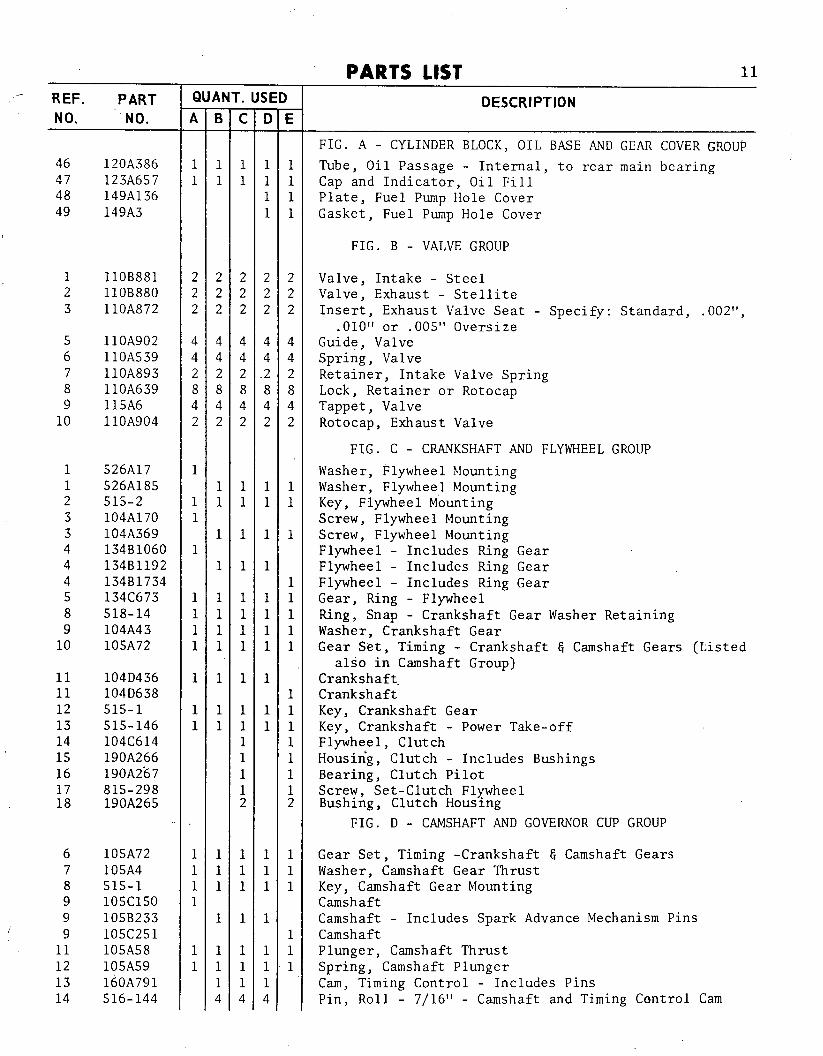
FIG. A - CYLINDER BLOCK, OIL BASE AND GEAR COVER GROUP
Tube, Oil Passage - Internal, to rear main bearingCap and Indicator, Oil FillPlate, Fuel Pump Hole CoverGasket, Fuel Pump Hole Cover
FIG. B - VALVE GROUP
Valve, Intake - SteelValve, Exhaust - StelliteInsert, Exhaust Valve Seat - Specify: Standard, .002”,
.010” or .005” OversizeGuide, ValveSpring, ValveRetainer, Intake Valve SpringLock, Retainer or RotocapTappet, ValveRotocap, Exhaust Valve
FIG. C - CRANKSHAFT AND FLYWHEEL GROUP
Washer, Flywheel JlountingWasher, Flywheel MountingKey, Flywheel MountingScrew, Flywheel MountingScrew, Flywheel MountingFlywheel - Includes Ring GearFlywheel - Includes Ring GearFlywheel - Includes Ring GearGear, Ring - FlywheelRing, Snap - Crankshaft Gear Washer RetainingWasher, Crankshaft GearGear Set, Timing - Crankshaft G Camshaft Gears (Listed
also in Camshaft Group)Crankshaft.CrankshaftKey, Crankshaft GearKey, Crankshaft - Power Take-offFlywheel, ClutchHousin’g, Clutch - Includes BushingsBearing, Clutch PilotScrew, Set-Clutch FlywheelBushing, Clutch Housing
FIG. D - CAMSHAFT AND GOVERNOR CUP GROUP
Gear Set, Timing -Crankshaft G Camshaft GearsWasher, Camshaft Gear ThrustKey, Camshaft Gear MountingCamshaftCamshaft - Includes Spark Advance Mechanism PinsCamshaftPlunger, Camshaft ThrustSpring, Camshaft PlungerCam, Timing Control - Includes PinsPin, Roll - 7/16” - Camshaft and Timing Control Cam

12
REF. PART
NO. NO.
151617181920
3
456
7
81112
1233455A6
6
6
791011121213141.516161717181920
160A790516A146160A999518-185160A72711OA1283
112-71
112A69112A3114B28
113A88
,805-10114A36114B145
d .
149D693149A648502-65502-2149A611502-2502-20142A412
142A435
142A446
145B266154A360141A78153-263154D656154D356154A13149A45149A3154C658154C899154C659154C898145B264503-107145A271
QUANT. USED
i—
2
242
2
424
111
1111
12111
2121
1
111
<—
221211
2
242
2
424
1
1
111
1
12111
212
1
111
F—
221211
2
242
2
424
1
1111
1
211
1212
1
1
1
F—
221211
2
242
2
424
1
1
211
1
1
1
.—
F—
2
242
2
424
1
1
21
1
1
1
1
1
PARTS LIST
DESCRIPTION[’
FIG. D - CAMSHAFT AND GOVERNOR CUP GROUP (Cont.)Weight Assembly, Timing Control - Includes PinsPin, Groove - 1“ - Timing Control CamRetainer, Timing Control (Replaces #160A726)Lock, Timing Control RetainerSpring, Timing ControlCover, Timing Control
FIG. E - CONNECTING ROD AND PISTON GROUP
Piston and Pin - Includes Pin Retaining Rings - Specify:Standard, .010”, .020”, .030” or .040” Oversize “
Pin, Piston - Specify: Standard or ,002” OversizeRing, Retaining - Piston PinRod Assembly, Connecting (Forged) Includes Bushing
and Place Bolts - Less InsertsRing Set, Piston - For One Piston - Includes Expander -Specify: Standard .010”, .020”, .030” or .040” Oversize
Bolt, Place - Connecting RodBushing, Piston Pin - Connecting RodInsert Bearing, Connecting Rod - Specify: Standard,
.002”, .010”, .020” or,.030” Undersize (Replaces#l14B55)
FIG. F - FUEL SYSTEM GROUP
Pump, Fuel - ONW Mfr.Rod, Fuel Pump PrimerElbow, Carburetor Inlet (45°)Elbow, Carburetor InletLine, Fuel - Fuel Pump to CarburetorElbow, Fuel Pump OutletElbow, Street - Fuel Pump InletCarburetor - With Special Combined Throttle Lever andThrottle
Carburetor - With Special Combined Throttle Lever andThrottle
Carburetor - With Special Combined Throttle Lever and.Throttle
Gasket, Carburetor Adapter to ManifoldGasket, Exhaust Tube to ManifoldGasket, Carburetor MountingBracket and Clamp, Manual Choke RodManifold, IntakeManifold, IntakeGasket, Intake Nlanifoldto Cylinder BlockSpacer, Fuel Pump MountingGasket, Fuel Pump Mounting or Hole Cover PlateTube, Exhaust - Left - #l-CylinderTube, Exhaust - Left - #l-CylinderTube, Exhaust - Right -#2-CylinderTube, Exhaust - Right - #2-CylinderAdapter, Carburetor - Leveling WedgeClamp, Air Inlet To CarburetorInlet, Carburetor Air

REF. PARTNO. NO.
202021212223
24
252627282930313233
1123“455
.,678
91011
(, 12
131314
15
145A353145A367503-280503-280140A211855-11
814-151
526-63518-176140C865140-8&6140P837140B869140B863140C862520A114
142A412
142A435
142A446
142K371
142K428
142-33815-103815-109815-91142-55142-205142-217142-420142A39142A31148A17
142-49142-32142-285
142-361142A41O145B361142A40
142-282
QUAI
7—
1
12
2
21
1
1
1
1122111
112
111
11
1
1
F—
1
1
2
2
21
1
1
1
112211
1112
111
11
1
1
?—
1
1
2112
1224
1
1
112211
1111
111
1
11
1
SIi—
1
1
1
4
1
1
112211
1111
111
1
11
1
)
E—
1
4
1
1
112211
1111
111
1
11
1
PARTS LIST 13
DESCRIPTION
FIG. F - FUEL SYSTEM GROUP (Cont.)
Inlet, Carburetor Air (Replaces #145A305)Inlet, Carburetor AirClamp, Air Inlet to SleeveClamp, Air Cleaner to Air InletSleeve, Air Cleaner HoseWasher, Lock - Tooth Type, Countersunk - 1/4” -
Carburetor MountingScrew, Flat Head Machine - 1/4-20 x 3/4” -
Carburetor MountingWasher, Flat Copper - Fuel Pump MountingClip, Carburetor Control SecuringCleaner; Air - CompleteElement, Air Cleaner - Includes GasketElement, Air CleanerBody ~ Bracket, Air CleanerPlate, Element RetainerSpring, Element Retainer PlateStud, Exhaust Tube to Manifold
FIG. G - CARBURETOR PARTS GROUP
Carburetor - With Special Combined Throttle Lever andThrottle Stop
Carburetor - With Special Combined Throttle Lever andThrottle Stop
Carburetor - With Special Combined Throttle Lever andThrottle Stop
Repair Kit, Carburetor Parts - Includes Parts Marked* and **.
Repair Kit. Carburetor Parts - Includes Parts Marked* and#.
*Gasket Kit, CarburetorScrew, Bowl Cover - #10-24 x 1/2”Screw, Bowl Cover - #10-24 x 5/8”*Screw, Choke Fly - #4-40 X 3/16”Fly Assembly, ChokeSleeve Assembly, ChokeShaft Assembly, ChokeShaft Assembly, Choke*Shaft, FloatGasket, Body to Bowl
‘Gasket, Float Valve Seat and Main Adjusting NeedleRetainer
*Valve and Seat Assy., Float - Includes GasketGasket, NozzleNozzle Assembly
Float and Lever Assembly (Replaces #142-38)Lever, Idle Stop G ThrottleLever, Idle Stop G Throttle
*Needle, Idle Adjusting
Spring, Idle Needle Adjusting

14 PARTS LIST
REF. PARTNO. NO.
1617181920202121222324252627282930313233
12
3
456789101112141516171819
1
2
142A35812-65815-72142-369142A368142-454142-370142-393142-46142-206142-45516A27142-41
505-53142-42142-343813-102870-53142-15
149D693149K526
815-148
815-147
149-96149A95149A582149A672149A539149A675516A113
149-710149A551509-65149A404149A3518-129149A858
120A491
120B400
QUANT. USED
i—
11
211
1
1111111211
1114
2
221111111121111
1
1
E—
11
211
1
11
2111
1114
2
221111111121111
1
1
PL
—
11
21
1
1
11
2111
1114
2
221111111121111
1
i—
1121
1
1
11
2111
1
E—
1121
1
1
11
2111
1
DESCRIPTION (“
FIG. G - CARBURETOR PARTS GROUP (Cont.)
Spring, Throttle Stop Adjusting ScrewScrew, Throttle Stop Adjusting - #6-32 x 5/8”*Screw, Throttle Fly - #4-40 x 1/4”Fly, Throttle*Shaft Assembly, Throttle*Shaft, ThrottleNut and Jet, Nozzle
#Nut and Jet, NozzleRetainer, Main Adjusting NeedlePacking, Main Adjusting NeedleRetainer, Main Adjusting Needle PackingPin, Main Adjusting Needle*Needle, Main AdjustingBody Assembly - Not Sold SeparatelyPlug, Gas InletNeedle Assembly - Includes Packing Nut and Retainer#Bushing, Throttle ShaftScrew, Idle Stop and Throttle Lever Screw - #10-32 x 5/8”Nut, Idle Stop and Throttle Lever Screw - #10-32 Hex SteelPlug, Nozzle
* and ** _ Contained in Repair Kit #142K371.* and # - Contained in Repair Kit #142K428.
FIG. H. - FUEL PUMP PARTS GROUP
Prep, FuelRepair Kit, Fuel Pump - Includes Parts Llarked’Body, Upper - Not Sold SeparatelyScrew, Hex Head Self Tapping - #8-32 x 7/8” - PumpAssembly
Screw, Phillips Flat Head Self Tapping - #6-32 x 5/8”- Valve Retainer
*Valve and Cage*Gasket, Valve*Diaphragm Assembly*Spring, DiaphragmRetainer, Valve Cage*Spring, Rocker ArmPin, Rocker ArmBody, Lower - Not Sold SeparatelyArm and Link Set (Individual Parts Not Supplied)Lever, Hand PrimerSeal, !1011 Ring
Spring, Fuel Pump Priming Lever*Gasket, Fuel Pump MountingRing, I!E!’Retainer - Priming Lever Shaft
*Gasket, Diaphragm
* - Contained in Repair Kit #149K526.
FIG. I - OIL PUMP GROUP\
Prep, Oil -
I Intake, Oil
Internal Parts Not Sold SeparatelyPump - Includes Cup, Screen and Pipe

PARTS LIST 15
REF. PARTNO. NO.
234567891010111112131415
12345568910
101111111212A131313151616A1717A1820212224242526
120B648120A187120A140120A398
120K161526-66193A108226A577501A118501A9502A20502-2122-75333-114323-397323-396
160A930160A150160A75160A2166A376166A438312A69160A43508-5160A776
160A723167A1308167A1073167A1408160C792166C346167A1309167A1459167A1491167-177160A642160A963160A488503P458160A558160A428332A319332A284336A565336A1574160A261304A60
QUANT. US
i
1
1
1
1
111
1
1
1
1
1
1
221
1
1
1
21
1
21111
11
i—
1
1
1
11
1
1
1
1
1
1
1
1
1
2
1
1
1
1
21
121111
11
E—
1111
1
1
1
1
1111
1
11
1
1
1
1
2
1
12111
1
i—
1
11
1
11
1
1
111
1
1
1
1
1
1
1
1
2
1
12111
1
1
)
:—
1
11
1
11
11
1
11
1
11
1
1
1
1
12
1
12111
1
DESCRIPTION
FIG. I - OIL PUMP GROUP (Cont.)
Intake, Oil Pump - Includes Cup, Screen and PipeStud and Nut - By-Pass AdjustingSpring, By-Pass ValveValve, By-Pass
Gasket Kit, Oil PumpWasher, Copper - By-Pass Stud Nut
Sender, Oil PressureLead, Oil Pressure SenderLine, Flexible OilLine, Flexible OilElbow, Street - Oil Line to BlockElbow, Inverted - Oil Line to BlockElement, Oil FilterHeater, Oil Immersion (Optional Equip.)Base, Heater Male Plug (Optional Equip.)Boot, Heater Plug Base (Optional Equip.)
FIG. J - IGNITION GROUP
Cover, Breaker Box (Replaces #160A152)Gasket, Breaker Box CoverCam, Point Gap AdjustingPoint Set, BreakerBracket, Coil and Resistor Mounting ~Bracket, Coil and Resistor MountingCondenser, Breaker PointsGasket, Breaker Box and Spacer MountingGrommet, Spark Plug Cable - Blower HousingPlunger, Breaker - Includes Plunger, Diaphragm and
Guide (Replaces #160A636)Plunger, BreakerCable, Spark Plug - Right Hand (Short)Cable, Spark Plug - Right Hand (Short)Cable, Spark Plug - Right Hand (Short)Coil, Ignition (Replaces #160C483)Coil, IgnitionCable, Spark Plug - Left Hand (Long)Cable, Spark Plug - Left Hand (Long)Cable, Spark Plug - Left Hand (Long)Plug, SparkBox Assembly, Breaker - CompleteBox Assembly, Breaker - CompleteClamp, CoilClamp, CoilNipple, Rubber - Coil“Strap, point Set to Terminal BlockBlock, Insulator - TerminalScrew, TerminalLead, Breaker Box GroundLead, Breaker Box GroundWick, Breaker Box Oil DrainResistor, Ignition - For 12-Volt System
16
REF. PARTNO. NO.
2727282930313233
34
1122233456789
123344
4
5678910
336A1270336A723304-14336A1045160B633508A2304A61O160A929
160A263
134D589134D1644134DI058134D1647134C1731134C1075134D1645134B670517-9134D1638134D1639517-35508-84
191C129191C575191C150191C511191-543191-620
191P660
191-542191-544511-76191B576191-621191-622
191C150191C511
QUANT. USED
i—
1
2111
1
1
1
1
11
1
1
1
i
121L
1
1
1
1
1
1
1
1
11
1
.
.
1~
1
11
1
1
1
11
111
1
1
1
1111
1
F—
121
11
1
1
1
1
11
—:—
1
21
11
1
1
1’
11
111
1
1
1
1111
1
PARTS LIST,/”
DESCRIPTION(
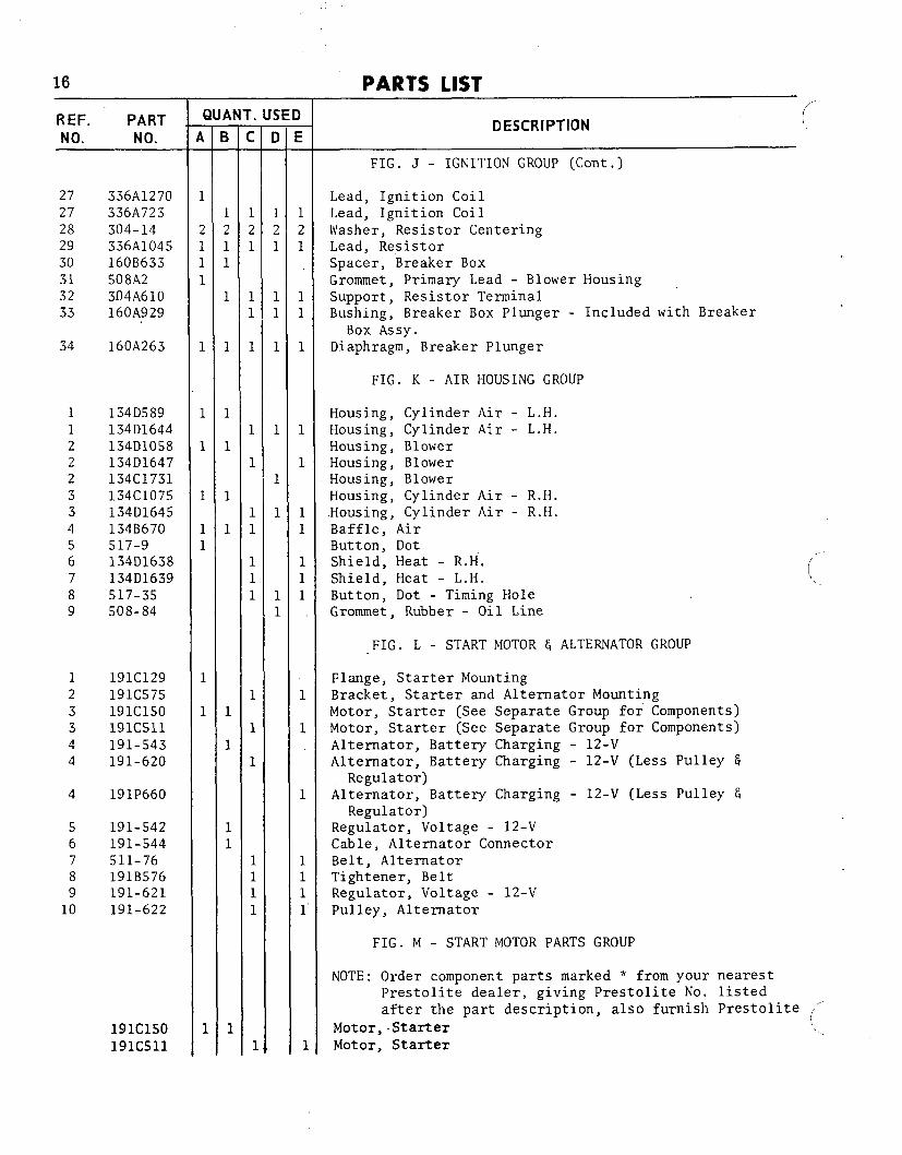
FIG. J - IGNITION GROUP (Cont.)
Lead, Ignition CoilLead, Ignition CoilWasher, Resistor CenteringLead, ResistorSpacer, Breaker BoxGrommet, Primary Lead - Blower HousingSupport, Resistor TerminalBushing, Breaker Box Plunger - Included with Breaker
Box ASSY.
Diaphragm, Breaker Plunger
FIG. K - AIR HOUSING GROUP
Housing, Cylinder Air - L.H.Housing, Cylinder Air - L.H.Housing, BlowerHousing, BlowerHousing, BlowerHousing, Cylinder Air - R.H.Housing, Cylinder Air - R.H.Baffle, AirButton, DotShield, Heat - R.H.Shield, Heat - L.H.Button, Dot - Timing HoleGrommet, Rubber - Oil Line
,.-“(I.
FIG. L - START MOTOR & ALTERNATOR GROUP
Flange, Starter MountingBracket, Starter and Alternator MountingMotor, Starter (See Separate Group for Components)Motor, Starter (See Separate Group for Components)Alternator, Battery Charging - 12-VAlternator, Battery Charging - 12-V (Less Pulley 6
Regulator)Alternator, Battery Charging - 12-V (Less Pulley &
Regulator)Regulator, Voltage - 12-VCable, Alternator ConnectorBelt, AlternatorTightener, BeltRegulator, Voltage - 12-VPulley, Alternator
FIG. M - START MOTOR PARTS GROUP
NOTE: Order component parts marked * from your nearestprestolite dealer, giving Prestolite No. listedafter the part description, also furnish Prestolite (“
Motor, -Starter (~..
Motor, Starter..

,,.~REF. PARTNO. NO.
1
2
345678891011
12
191-517*
191-513***
191P271*****
*
191-543191-620191P660
*************************
j
A—
11
1
11
11
1
1
11
1
~
3
11111111
111
1
1
1
1
4
1
1
1
1
1
1
1
1
.
F—
1
1
1
1
1
1
1
1
1
1
1
1
1
1
1
1
1
1
1
1
1
3
1
1
)
E—
1
1
1
11
1
1
111
1
1
1
1
1
1
1
1
1
1
1
3
3
1
1
PARTS LIST 17
DESCRIPTION
FIG. M - START MOTOR PARTS GROUP (Cont.)
ArmatureCoil Assembly Package, Field - #P20-14Brush Set, ServiceHead Assembly, Brush End - #P19-27Band, Cover - #P36-321Bearing Assembly, Intermediate - #P36-4Drive Assembly, BendixHousing, Pinion - #P21-156Housing, Pinion - #P21-277Bearing, Drive End - #P24-23Spring Set, Brush (Set of 4) - #P50-263Washer; Armature Thrust (Pkg. - Use as Required) -
#P90-263Terminal, Stud (Pkg.) - #P90-333
BATTERY CHARGING ALTE~ATOR PARTS GROUP (NotIllustrated)
NOTE: Order component parts marked * from your nearestdealer, giving manufacturers No. listed afterthe part description, also check nameplate and
furnish manufacturers alternator No.
Alternator, Battery Charge - 12-V Motorola
Alternator, Battery Charge - 12-V PrestoliteAlternator, Battery Charge - 12-V PrestoliteBearing, Ball-Brush End - #n-2Bearing, Ball-Brush End - #X-3433Bearing, Ball - Drive End - # 11-1Bearing, Ball - Brush End - #X-3416Bolt, Housing Thru - # 20-1Bolt Package, Thru - #ALA-20BSBrush G Holder Assembly - # 3-1Brush G Holder Assembly - #ALE-1045Cover, Brush Holder - #3-3Brush Set - #ALE-1012KSSpring Set, Brush - #ALA-19SDiode Assembly, Isolation - #l-3Diode, Output - #P90-761Diode Assy., Negative (3 diodes with black print) - #l-2Diode, Negative - Isolation - #XA-944CDiode, Negative - #XA-944JDiode Assy., Positive (3 diodes with red print) - #l-1Diode, Positive - #XA-943CDiode, Positive - #XA-943FFan, Ventilation - #7-8Fan, Ventilation -.#PU-625Housing, Front - #14-1Housing, Front - #ALE-1043EHousing, Front - #ALE-1043KHousing, Rear - #14-2
18 PARTS LIST
REF. PARINO. NO.
***
*****************
168K67
168K88
1A
F—
21
1
1
1
1
1
1
1
r.F—
1
1
1
1
1
1
1
1
1
1
1
SED
i—
1
1
1
1
1
111
1
DESCRI PTlON (-
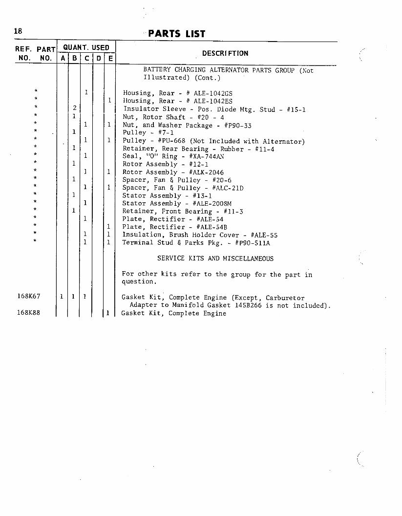
BATTERY CHARGING ALTE~ATOR PARTS GROUP (NotIllustrated) (Cont.)
Housing, Rear - # ALE-1042GSHousing, Rear - # ALE-1042ES
Insulator Sleeve - Pos. Diode Mtg. Stud - #lS-lNut, Rotor Shaft - #20 - 4Nut, and Washer Package - #P90-33Pulley - #7-1Pulley - #PU-668 (Not Included with Alternator)Retainer, Rear Bearing - Rubber - #n-4Seal, “O” Ring - #XA-744ANRotor Assembly - #12-1Rotor Assembly - #ALK-2046Spacer, Fan G Pulley - #20-6Spacer, Fan 6 Pulley - #ALC-21DStator Assembly - #13-1Stator Assembly - #ALE-2008MRetainer, Front Bearing - #n-3Plate, Rectifier - #ALE-54Plate, Rectifier - #ALE-54BInsulation, Brush Holder Cover - #ALE-55Terminal Stud & Parks Pkg. - #P90-511A
SERVICE KITS AND MISCELLANEOUS
For other kits refer to the group for the part inquestion.
Gasket Kit; Complete Engine (Except, CarburetorAdapter to Manifold Gasket 145B266 is not included).
Gasket Kit, Complete Engine
(,,
.,
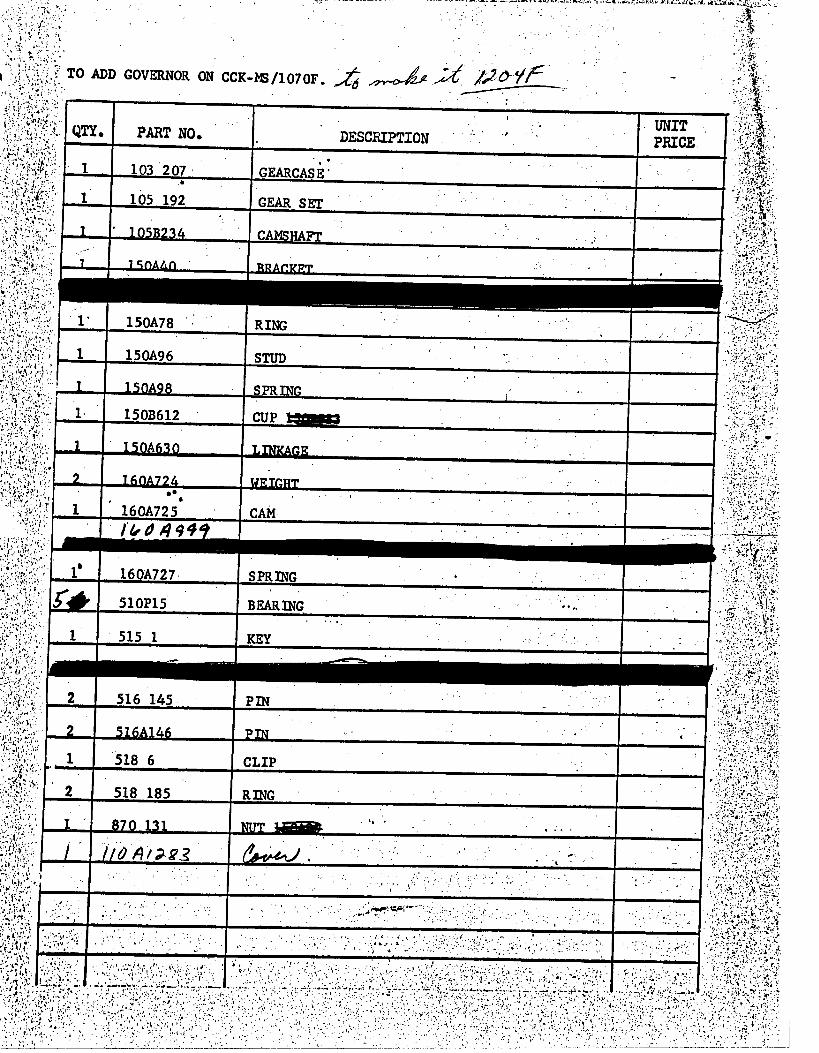
ADD GOVERNOR
~mG ~~ ‘“
,.,.
:.$..;4 .../ ;., ,
,,.s,,,. (,: .,
., :.,’ )~t..
........ . . ...---- ..-: -,;,:..-
,: !.+,.,.,,,j,,:, ,.!.? .;. -,.>,.i:,.,<, ,
‘-,,, ‘.; ,.~j.?[.i;,~,$ ~,,,.<,’,:,;,.! y,,,?,, ..,., ; 1’,~~::,I!.!:;.’;>:..;4,:,.,,.,.“:.,~.,ti‘ ii, , ),
,: ., .-, , !:’>.’ ,.
. -. ~,>.., ~; ,,,
..; :,,l .!.,
,.,!, ,.
. . . . . . . . . ,,. ,,+..’. , .,, ,, -.
. :;.!’”,:. . . . . . ,, .,, .,
. . . . . ,, .”’.,’.
. .,..:; . .. ,.,,, .,, .-
,. . i .,. .,, :.., ... . . . . . . ... . ~
. . . ,., L, . -.,.;..”,::’ ,: V,.z, =.-.,,,,:,<,,<,, .; :;.“’”* -.’! ,>,.: ,. .,,.,: ..t ..4: ,. .-.
.,, ,J,., ,-. , ;; !,
-,
,,: , —,. : -— . . . .——.