once the files have been loaded to the computer, efb can be started … · once the files have been...
TRANSCRIPT

1
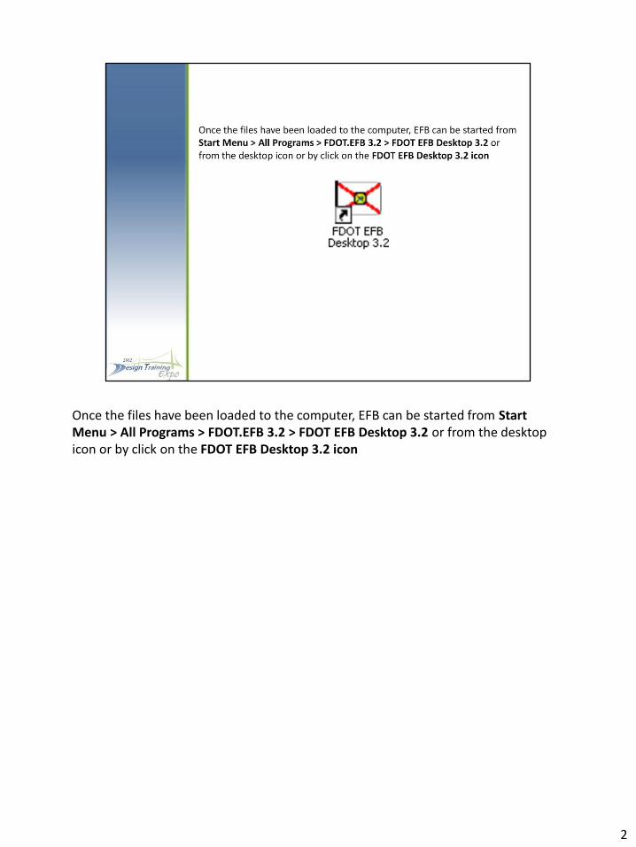
Once the files have been loaded to the computer, EFB can be started from Start Menu > All Programs > FDOT.EFB 3.2 > FDOT EFB Desktop 3.2 or from the desktop icon or by click on the FDOT EFB Desktop 3.2 icon
2

This is the EFB 3 desktop as it first opens. The desktop has all the same functionality as the data collector program plus a few others that will be covered. Just like Data Collector version you have to create or open a SDF file before you can start using the desktop. The SDF file has replaced the RAW file. The reason for the new SDF file is because is based on a sequel database format. And they could not crack the code for the RAW file.
3

Most of the time you will be opening an .SDF file that you have copied from the data collector. The Data and CTL tabs are grayed out if you click on one of them you….
4
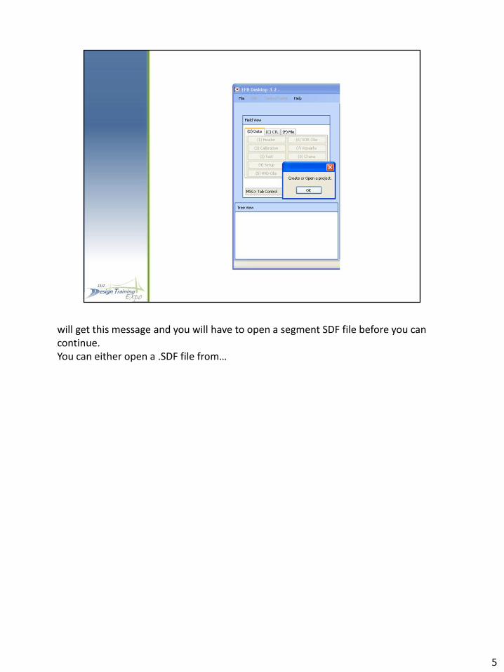
will get this message and you will have to open a segment SDF file before you can continue. You can either open a .SDF file from…
5

the File tab and selecting the Open button or…
6

from the File option in the Menu bar. Once you have made you choice…
7
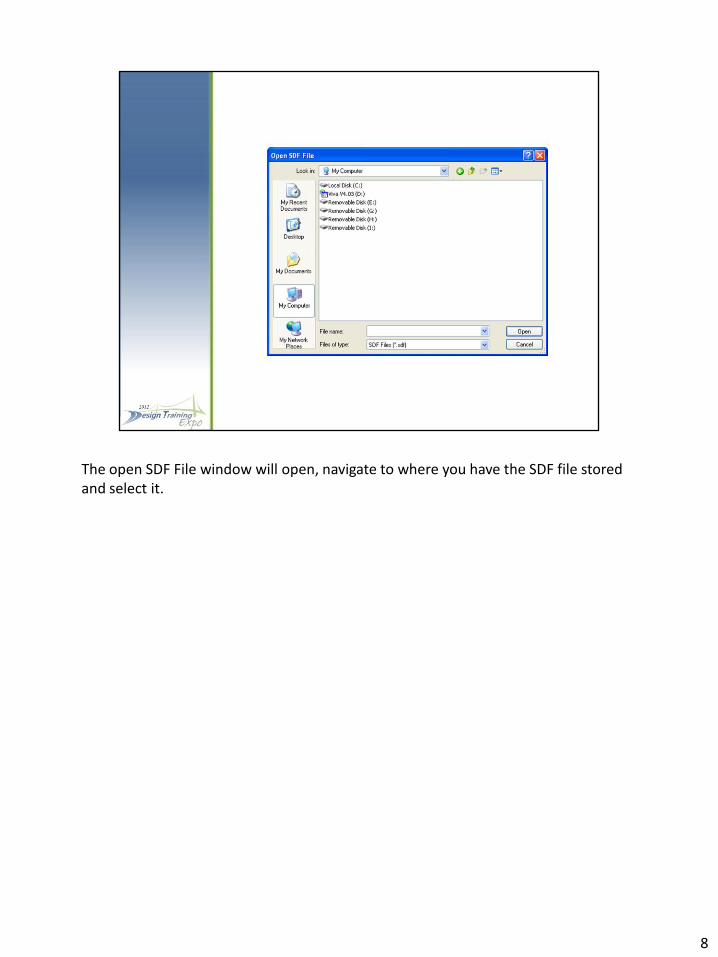
The open SDF File window will open, navigate to where you have the SDF file stored and select it.
8

The segment file name will be shown in Header of the desktop and the Data and CLT tabs are now available to be selected. Also you will notice that there is information showing up in the Tree View. From here….
9
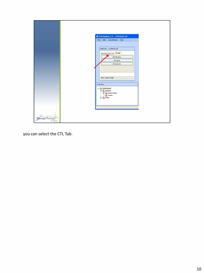
you can select the CTL Tab.
10
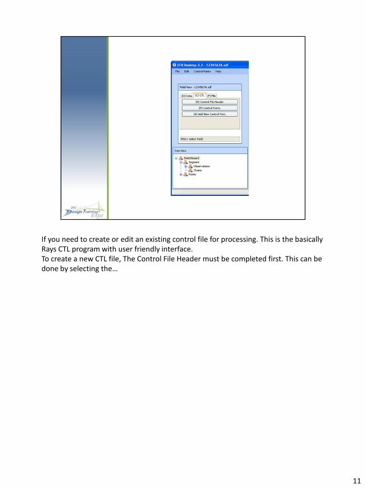
If you need to create or edit an existing control file for processing. This is the basically Rays CTL program with user friendly interface. To create a new CTL file, The Control File Header must be completed first. This can be done by selecting the…
11

(H) Control File Header button or by…
12

Selecting Control Points Setting under Control Points in the Menu Bar…
13
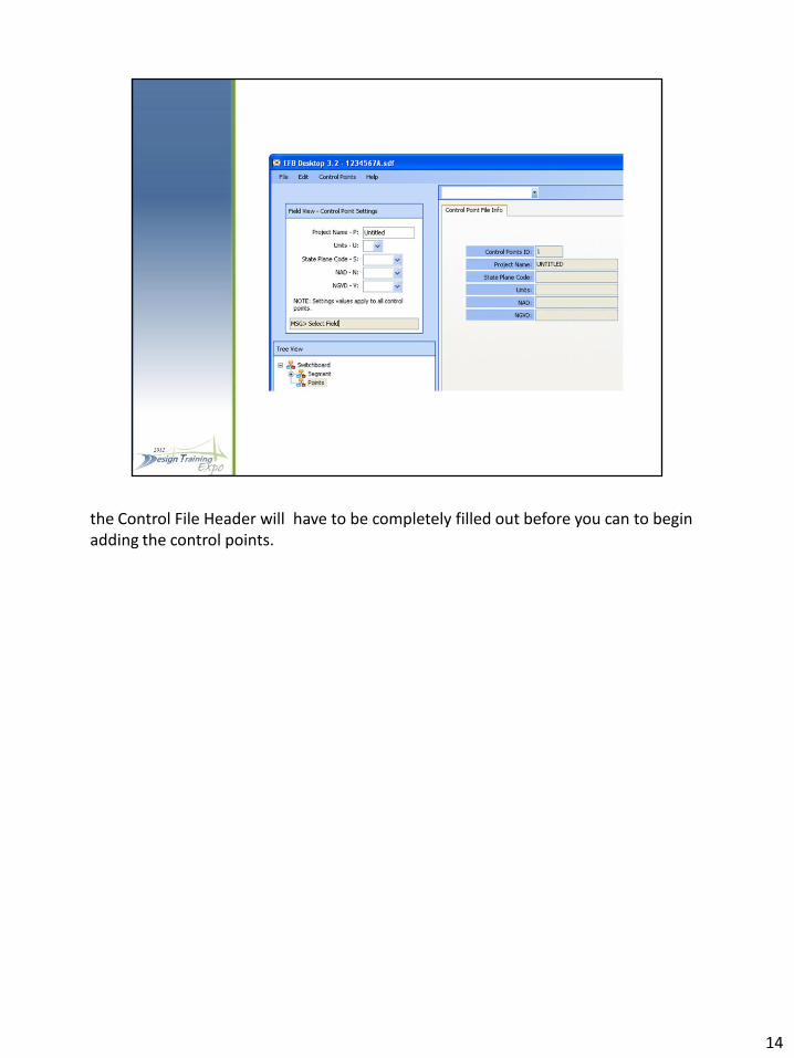
the Control File Header will have to be completely filled out before you can to begin adding the control points.
14

Once you have filled out the information make sure the cursor in in the message field and press “0” (Zero button) to store then hit Enter to go back to the main CTL tab.
15

To add a control point you can select the…
16
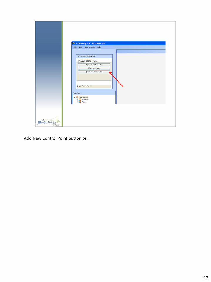
Add New Control Point button or…
17

Select “Add Point” from the Control Point from the Bar menu…
18

This will open the Control Point window. As you select the fields to fill in keep an eye on the message field, it will tell you what information goes in the box you are in. The 2nd columns of boxes after the X,Y, and E…
19
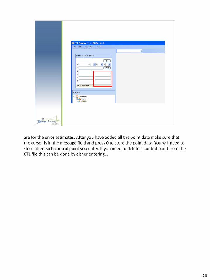
are for the error estimates. After you have added all the point data make sure that the cursor is in the message field and press 0 to store the point data. You will need to store after each control point you enter. If you need to delete a control point from the CTL file this can be done by either entering…
20

the point name in the name field and pressing the 3 key…
21
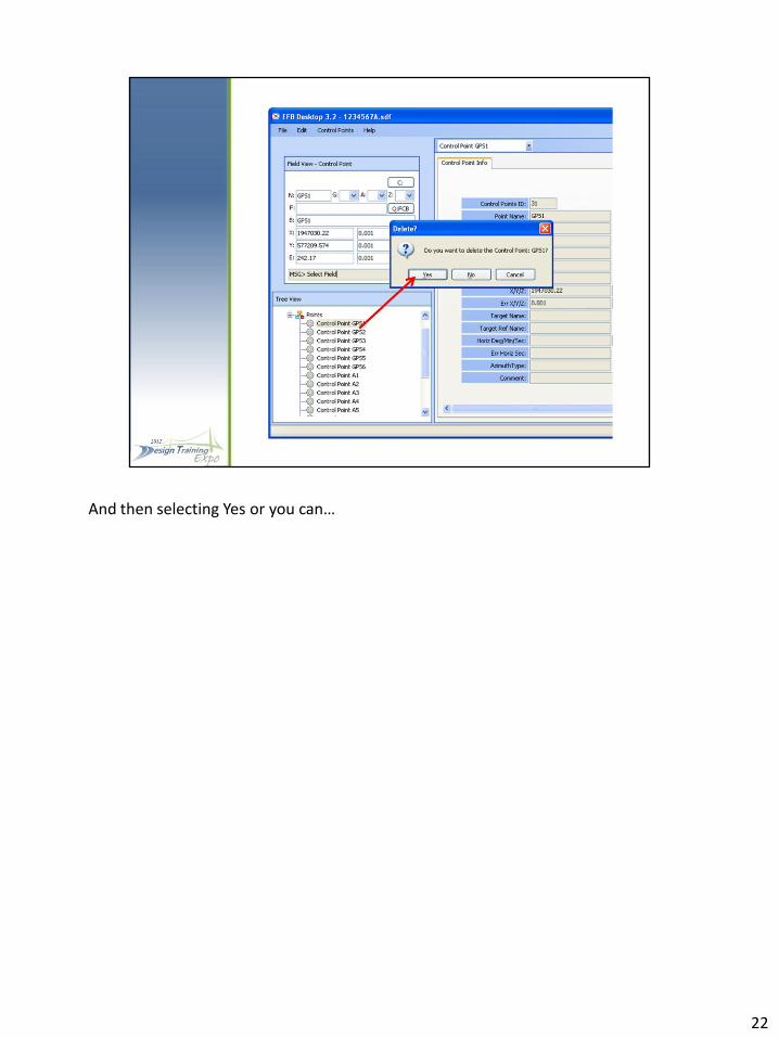
And then selecting Yes or you can…
22

Select the control point in the Tree View and then select…
23
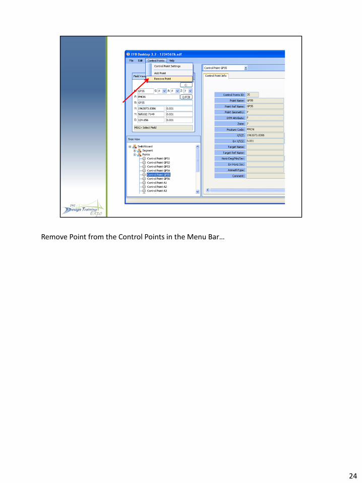
Remove Point from the Control Points in the Menu Bar…
24

And then select Yes.
25
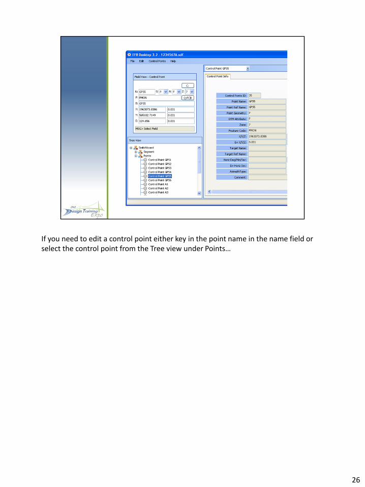
If you need to edit a control point either key in the point name in the name field or select the control point from the Tree view under Points…
26

make any corrections and then ensure that the cursor is in the message field and press zero to store. After you have completed creating or editing the segment control file make sure the cursor is in message filed and press the enter key to go back to the CTL main tab…
27

Then select the..
28
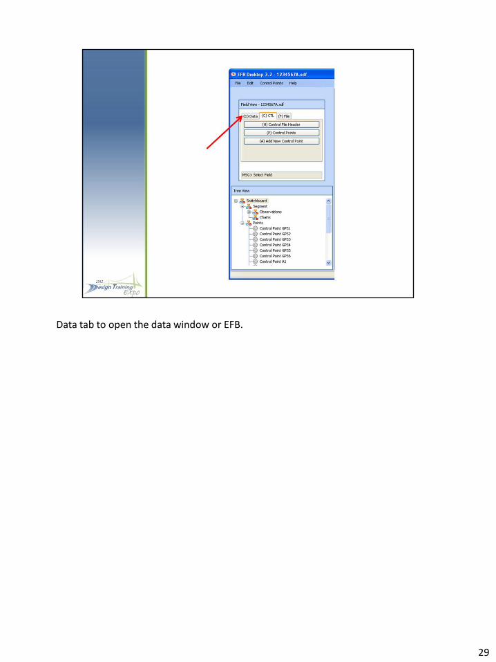
Data tab to open the data window or EFB.
29

The Data tab will allow you to review the field data and perform the same field edits that you just as you would in the field on a data collector. This was not designed to be a full editor any major edits are still going to be made in the OBS.
30
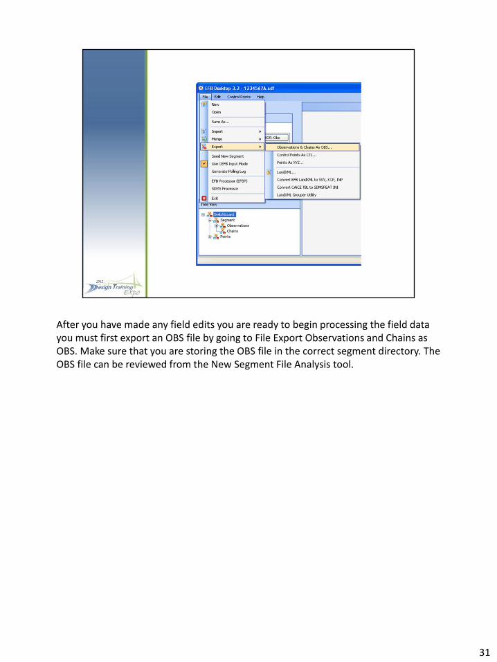
After you have made any field edits you are ready to begin processing the field data you must first export an OBS file by going to File Export Observations and Chains as OBS. Make sure that you are storing the OBS file in the correct segment directory. The OBS file can be reviewed from the New Segment File Analysis tool.
31

The Segment Files Analysis tool box opens when “EFB Processor (EFB)” is selected from the File Menu bar.
32

The Segment Files Analysis tool box runs EFBP to make it a little more user friendly. It is still running Dr. Hintz’s EFBP programs in the background so the same reports that you are used to seeing are still getting created.
33

Selecting the Browse… button will open the…
34
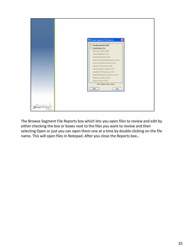
The Browse Segment File Reports box which lets you open files to review and edit by either checking the box or boxes next to the files you want to review and then selecting Open or just you can open them one at a time by double clicking on the file name. This will open files in Notepad. After you close the Reports box…
35

Focus is brought back to the Segment Files Analysis box. To change or review the Error Estimates before processing select the…
36
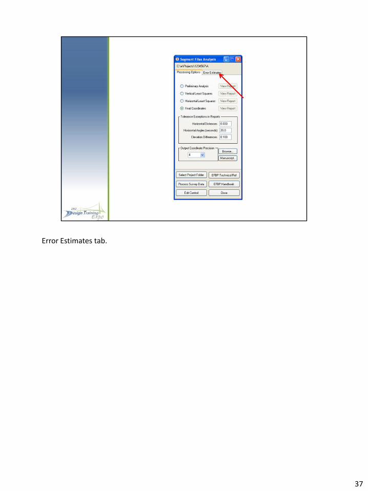
Error Estimates tab.
37
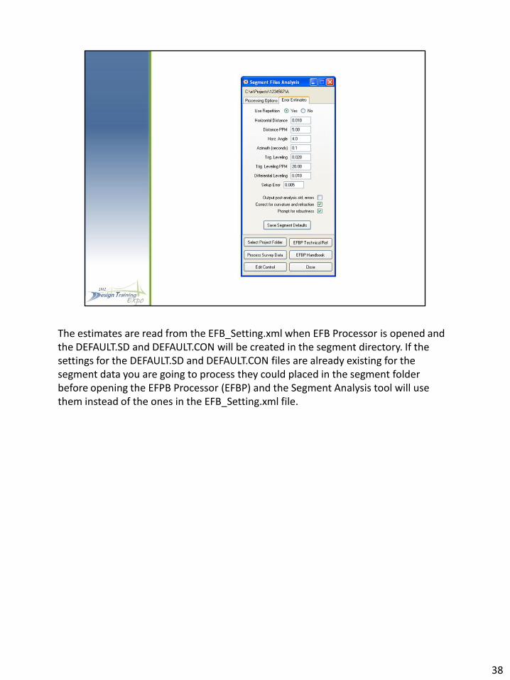
The estimates are read from the EFB_Setting.xml when EFB Processor is opened and the DEFAULT.SD and DEFAULT.CON will be created in the segment directory. If the settings for the DEFAULT.SD and DEFAULT.CON files are already existing for the segment data you are going to process they could placed in the segment folder before opening the EFPB Processor (EFBP) and the Segment Analysis tool will use them instead of the ones in the EFB_Setting.xml file.
38
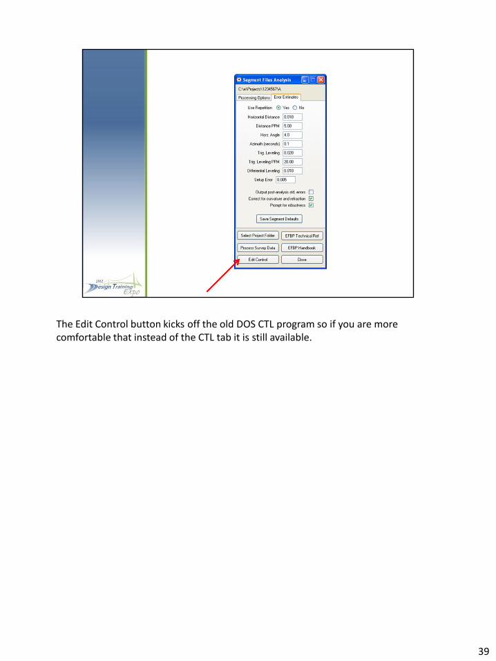
The Edit Control button kicks off the old DOS CTL program so if you are more comfortable that instead of the CTL tab it is still available.
39
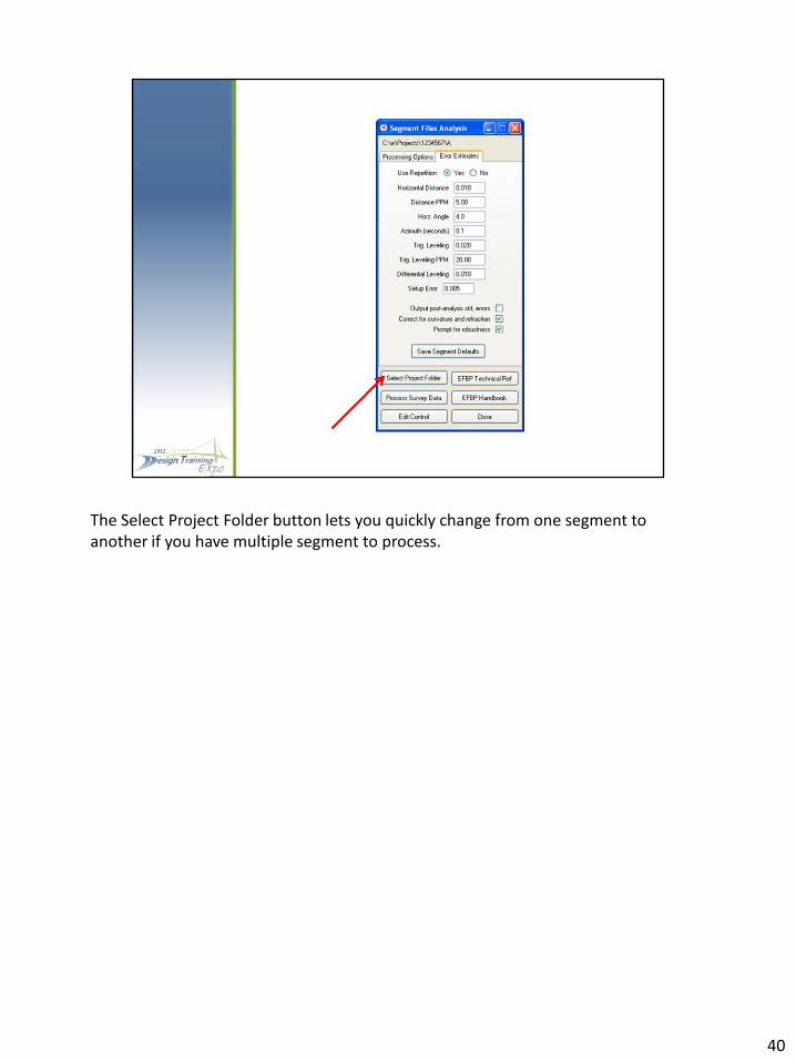
The Select Project Folder button lets you quickly change from one segment to another if you have multiple segment to process.
40

The Process Survey Data button runs EFBP. But before EFBP is run there are a few options back in the Processing Options Tab that you may want to look at.
41

Here you can select which report you want EFBP to Stop processing at, the default is Final Coordinates so you can review the .SUM file from the Browse button for all flagged issues.
42

Once you are ready to process click on the Process Survey Data button, after EFBP has run…
43

The View Report buttons in the Processing Options tab should be available, or you can view reports from the …
44

the Browse Button and select which report you want to review. If you are reprocessing a segment you will get a message…
45
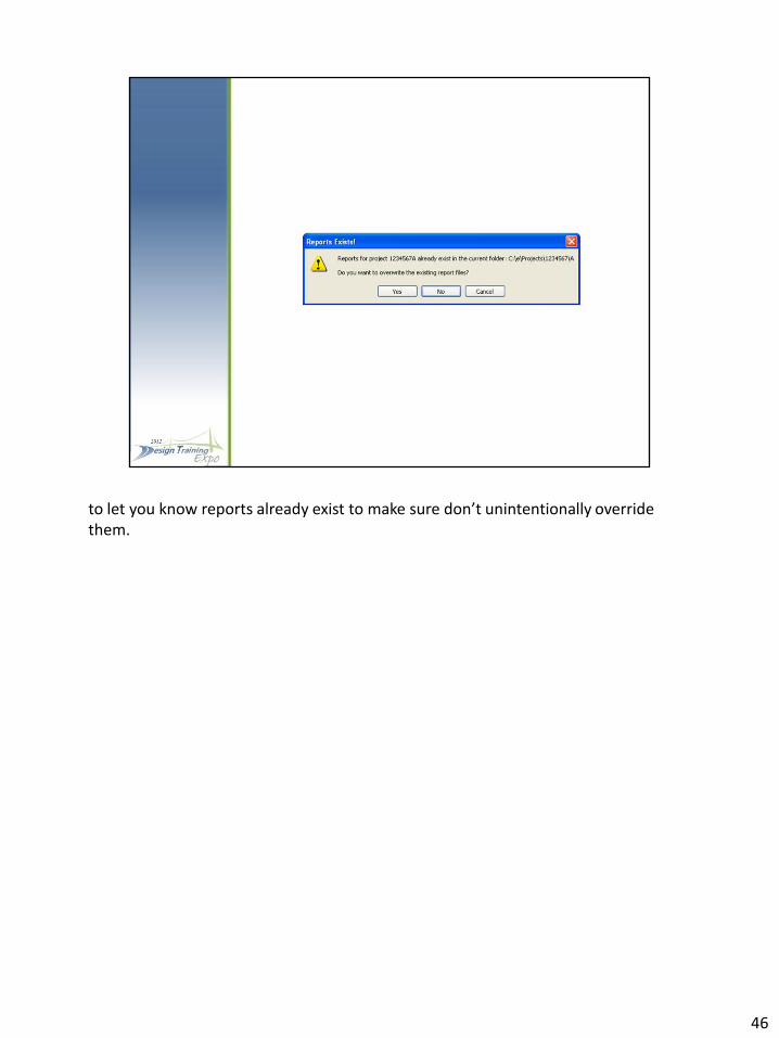
to let you know reports already exist to make sure don’t unintentionally override them.
46
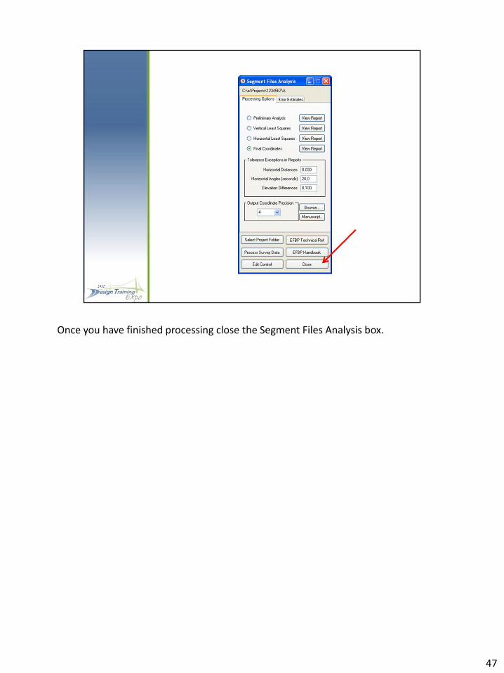
Once you have finished processing close the Segment Files Analysis box.
47
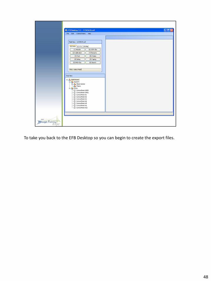
To take you back to the EFB Desktop so you can begin to create the export files.
48
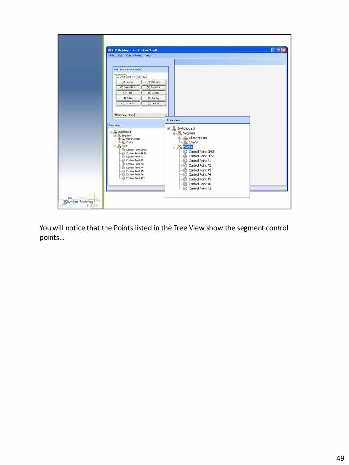
You will notice that the Points listed in the Tree View show the segment control points…
49

The final segment XYZ file will have to be imported into the segment SDF file to create the segment LandXML file. This file can read into MicroStation/Geopak and Civil 3D.The segment XML file is also used to create files to be read into CAiCE and GEOPAK. You may want to make sure that you have a clean back-up copy of all your SDF files before importing since the segment points will be written to the SDF file.
50
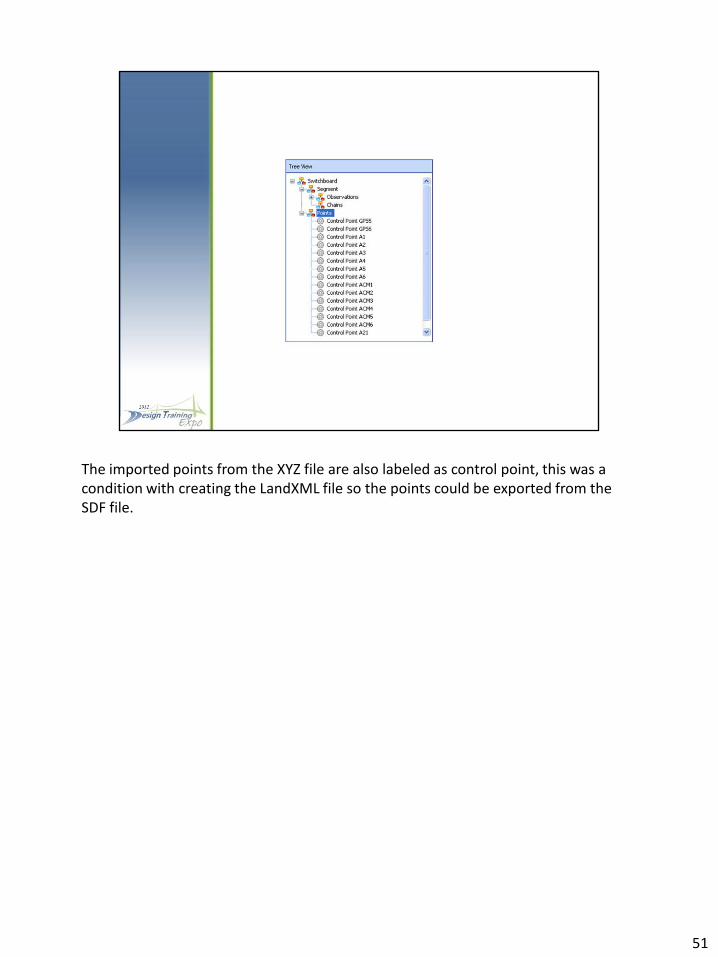
The imported points from the XYZ file are also labeled as control point, this was a condition with creating the LandXML file so the points could be exported from the SDF file.
51

To export the segment LandXML file go to File \ Export \ LandXML…
52
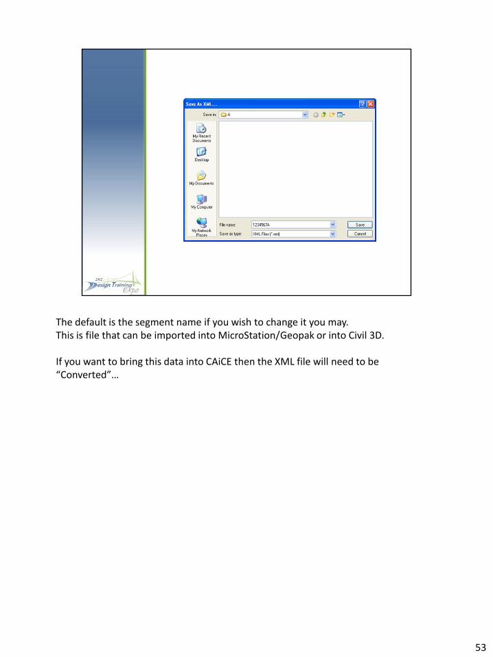
The default is the segment name if you wish to change it you may. This is file that can be imported into MicroStation/Geopak or into Civil 3D. If you want to bring this data into CAiCE then the XML file will need to be “Converted”…
53

The Conversion utility is opened from File \ Export \ Convert EFB LandXML to SRV, KCP, INP…
54

One the Conversion Utility opens select the “Input XML” button…
55

and select the segment XML file to should default to the segment folder.
56
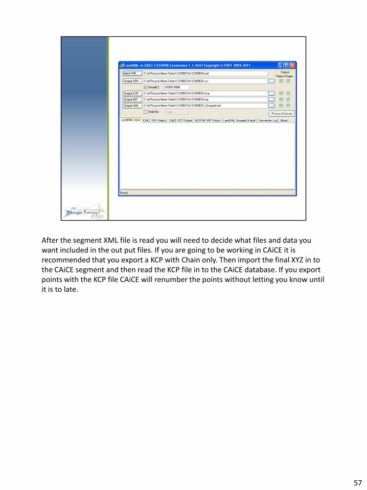
After the segment XML file is read you will need to decide what files and data you want included in the out put files. If you are going to be working in CAiCE it is recommended that you export a KCP with Chain only. Then import the final XYZ in to the CAiCE segment and then read the KCP file in to the CAiCE database. If you export points with the KCP file CAiCE will renumber the points without letting you know until it is to late.
57
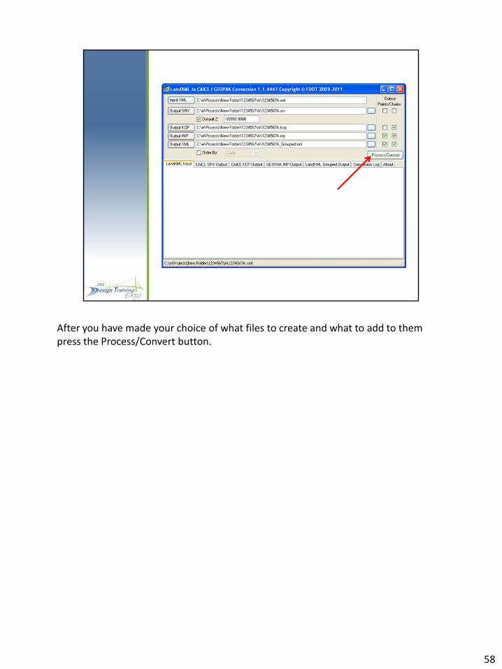
After you have made your choice of what files to create and what to add to them press the Process/Convert button.
58

After the files have been created review the Conversion Log Tab to see if there were any issues.
59

From here you can close the Conversion Utility and the EFB Desktop and move on to your CADD program.
60

61