one fire-lite place northford, ct 06472 (203) 484-7161 · one fire-lite place northford, ct 06472...
TRANSCRIPT

One Fire-Lite Place
Northford, CT 06472
(203) 484-7161
(203) 484-7118 (Fax)
AFP-100Intelligent Fire Panel
Installation, Programming and Operating Manual
PN 51010:A ECN 99-012
Document 51010
12/15/98 Revision A
WAenecauwitRuwhresto c
InWAconassmoins
CApro199Recomwir
All affeopenottes
ThandHocomhuminsF.
VeMovol
r canstem ising will
due toical
ards.
nchingr.
magew
ith avedblies
uals.
Fi
AndetwitSulos
An
Smas detfloomosenby esccirc
IMPcontranotabi
s arether
er fails,
. For once
control.
l
e bych
quireds should
F
s of the
nt leseunica-
Techn
RNING: This equipment generates, uses, and can radiate radio frequencyrgy and if not installed and used in accordance with the instruction manual, mayse interference to radio communications. It has been tested and found to comply
h the limits for class A computing device pursuant to Subpart B of Part 15 of FCCles, which is designed to provide reasonable protection against such interferenceen operated in a commercial environment. Operation of this equipment in aidential area is likely to cause interference, in which case the user will be requiredorrect the interference at his own expense.
stallation Precautions - Adherence to the following will aid in problem-free installation with long-term reliability:
RNING - Several different sources of power can be connected to the fire alarmtrol panel. Disconnect all sources of power before servicing. Control unit andociated equipment may be damaged by removing and/or inserting cards,dules, or interconnecting cables while the unit is energized. Do not attempt totall, service, or operate this unit until this manual is read and understood.
UTION - System Reacceptance Test after Software Changes: To ensureper system operation, this product must be tested in accordance with NFPA 72-3 Chapter 7 after any programming operation or change in site-specific software.
acceptance testing is required after any change, addition or deletion of systemponents, or after any modification, repair or adjustment to system hardware or
ing.
components, circuits, system operations, or software functions known to bected by a change must be 100% tested. In addition, to ensure that otherrations are not inadvertently affected, at least 10% of initiating devices that are
directly affected by the change, up to a maximum of 50 devices, must also beted and proper system operation verified.
is system meets NFPA requirements for operation at 0-49O C/32-120O F at a relative humidity of 85% RH (non-condensing) at 30O C/86O F.
wever, the useful life of the system's standby batteries and the electronicponents may be adversely affected by extreme temperature ranges andidity. Therefore, it is recommended that this system and its peripherals be
talled in an environment with a nominal room temperature of 15-27O C/60-80O
rify that wire sizes are adequate for all initiating and indicating device loops.st devices cannot tolerate more than a 10% I.R. drop from the specified devicetage.
Like all solid state electronic devices, this system may operate erratically obe damaged when subjected to lightning induced transients. Although no sycompletely immune from lightning transients and interferences, proper groundreduce susceptibility. Overhead or outside aerial wiring is not recommended,an increased susceptibility to nearby lightning strikes. Consult with the TechnServices Department if any problems are anticipated or encountered.
Disconnect AC power and batteries prior to removing or inserting circuit boFailure to do so can damage circuits.
Remove all electronic assemblies prior to any drilling, filing, reaming, or puof the enclosure. When possible, make all cable entries from the sides or reaBefore making modifications, verify that they will not interfere with battery,transformer, and printed circuit board location.
Do not tighten screw terminals more than 9 in-lbs. Over tightening may dathreads, resulting in reduced terminal contact pressure and difficulty with screterminal removal.
This system contains static-sensitive components. Always ground yourself wproper wrist strap before handling any circuits so that static charges are remofrom the body. Use static suppressive packaging to protect electronic assemremoved from the unit.
Follow the instructions in the installation, operating, and programming manThese instructions must be followed to avoid damage to the control panel andassociated equipment. FACP operation and reliability depend upon properinstallation.
re Alarm System Limitations While installing a fire alarm system may make lower insurancerates possible, it is not a substitute for fire insurance!
automatic fire alarm system - typically made up of smoke detectors, heatectors, manual pull stations, audible warning devices, and a fire alarm controlh remote notification capability can provide early warning of a developing fire.ch a system, however, does not assure protection against property damage ors of life resulting from a fire.
y fire alarm system may fail for a variety of reasons:
oke detectors may not sense fire where smoke cannot reach the detectors suchin chimneys, in walls, or roofs, or on the other side of closed doors. Smokeectors also may not sense a fire on another level or floor of a building. A secondr detector, for example, may not sense a first floor or basement fire. Further-re, all types of smoke detectors - both ionization and photoelectric types, havesing limitations. No type of smoke detector can sense every kind of fire causedcarelessness and safety hazards like smoking in bed, violent explosions,aping gas, improper storage of flammable materials, overloaded electricaluits, children playing with matches, or arson.
ORTANT! Smoke detectors must be installed in the same room as thetrol panel and in rooms used by the system for the connection of alarm
nsmission wiring, communications, signaling, and/or power. If detectors are so located, a developing fire may damage the alarm system, crippling itslity to report a fire.
Audible warning devices such as bells may not alert people if these devicelocated on the other side of closed or partly open doors or are located on anofloor of a building.
A fire alarm system will not operate without any electrical power. If AC powthe system will operate from standby batteries only for a specified time.
Rate-of-Rise heat detectors may be subject to reduced sensitivity over timethis reason, the rate-of-rise feature of each detector should be tested at leastper year by a qualified fire protection specialist.
Equipment used in the system may not be technically compatible with the It is essential to use only equipment listed for service with your control panel.
Telephone lines needed to transmit alarm signals from a premise to a centramonitoring station may be out of service or temporarily disabled.
The most common cause of fire alarm malfunctions, however, is inadequatmaintenance. All devices and system wiring should be tested and maintainedprofessional fire alarm installers following written procedures supplied with eadevice. System inspection and testing should be scheduled monthly or as reby National and/or local fire codes. Adequate written records of all inspectionbe kept.
CC WarningCanadian RequirementsThis digital apparatus does not exceed the Class A limits for radiation noiseemissions from digital apparatus set out in the Radio Interference RegulationCanadian Department of Communications.
Le present appareil numerique n'emet pas de bruits radioelectriques depassalimites applicables aux appareils numeriques de la classe A prescrites dans lReglement sur le brouillage radioelectrique edicte par le ministere des Commtions du Canada.
ical Publishing Document PRECAULG.PM6 12/31/96

.... 7
..... 7
... 9
.. 10
... 10... 10.. 10. 1011.. 11. 11
12.. 12... 12.... 12... 12
... 13
.. 14
.. 14.... 14... 15.... 15.... 16.. 16. 17.... 18
. 19
. 19
. 19
.. 19190
. 20
.. 21
.... 21
... 21... 21... 22.. 22.. 2323. 23.. 23... 24
.. 25
. 25
27
. 28
... 28
��������
����� �������������Overview...................................................................................................................
Features...................................................................................................................
Terminal Layout .......................................................................................................
Specifications............................................................................................................Overview ..............................................................................................................AC Power – TB8..................................................................................................Battery (Lead Acid Only) – J3 ..............................................................................Signaling Line Circuit (SLC) – TB6......................................................................Notification Appliance Circuits (NACs) – TB1 and TB2.......................................Alarm, Trouble and Supervisory Relays – TB3....................................................DC Power for Output Circuits (TB4).....................................................................
Controls and Indicators ............................................................................................LCD Display .........................................................................................................System Status LED Indicators .............................................................................Membrane Panel..................................................................................................Local Sounder ......................................................................................................
Circuits ....................................................................................................................
Components..............................................................................................................Main Circuit Board ...............................................................................................Cabinet ................................................................................................................Transformer Assembly.........................................................................................Batteries...............................................................................................................Addressable Devices ...........................................................................................
Intelligent Detectors..........................................................................................CMX and MMX Series Modules.......................................................................
Addressable Device Accessories.........................................................................
Optional Modules .....................................................................................................ACM-8R Relay Control Module............................................................................Fire•Lite RTM-8F Relay Module...........................................................................PIM-24 Printer/PC Interface Module....................................................................Veri•Fire 100 Software for Local Downloading.....................................................UDACT (Universal Digital Alarm Communicator/Transmitter)............................ 2DIM-485 Display Interface Module.......................................................................
Accessories................................................................................................................Dress Panel..........................................................................................................Battery Boxes .......................................................................................................CHG-120 Battery Charger ...................................................................................Annunciators ........................................................................................................
ACS Series LED Zone Type Annunciators ......................................................LCD-2x20 Series Remote Fire Annunciators .......................................................LDM Series Lamp Driver Modules – Graphic Annunciator ..................................
The LDM -32......................................................................................................The LDM-E32...................................................................................................
FCPS-24 Remote Field Charger Power Supply ...................................................
��������������Overview...................................................................................................................
Backbox Mounting ...................................................................................................
Component Installation.............................................................................................
AC and DC Power....................................................................................................AC Power and Earth Ground Connections ..........................................................
AFP-100 Instruction PN 51010:A 12/15/98 3

... 28... 28
29
0
1. 3132
3... 33... 33.. 33.. 33.. 33.. 33... 33.. 34... 34.. 36... 3637. 38. 39... 40
. 41.... 41. 41... 424243445678
49... 49... 4999. 49... 49... 5050
... 50... 50... 502
. 54
55... 55556
. 5656
Battery Power.......................................................................................................DC Power Output Connections............................................................................
Standard Relays (TB3)..............................................................................................Notification Appliance Circuits ................................................................................ 3
UL Power-limited Wiring Requirements ................................................................ 3General UL Power-Limited Wiring Requirements ................................................Fire•Lite RTM-8F UL Power-limited Wiring Requirements..................................
Wiring the Signaling Line Circuit (TB6) ................................................................. 3Overview ..............................................................................................................SLC Devices.........................................................................................................
ISO-X Modules.................................................................................................MMX Series Modules.......................................................................................CMX Series Modules........................................................................................Intelligent Detectors..........................................................................................Device Capacity ...............................................................................................
Style 4 Wiring and T-tapping................................................................................How to Calculate Branch Resistance ...................................................................Style 6 Wiring .......................................................................................................Measuring Resistance of the SLC ........................................................................Wiring a Style 4 Two-Wire SLC (supervised and Power-limited) .........................Style 6 Four-Wire SLC (Supervised and Power-limited) ......................................Style 7 Four-Wire SLC (Supervised and Power-limited) ......................................Shielded Wire Termination Requirements...........................................................
The ISO-X Module ...................................................................................................Purpose................................................................................................................Wiring an ISO-X Module.......................................................................................How to Set a Module Address .............................................................................The MMX-1 Monitor Module.................................................................................Wiring MMX-101 Monitor Modules ......................................................................Wiring MMX-2 Monitor Modules ..........................................................................Wiring a Style B IDC with MMX-1 Modules ........................................................ 4Wiring a Style D IDC with MMX-1 Modules ........................................................ 4Wiring a Style B IDC with MMX-2 Modules ........................................................ 4Wiring a Style D IDC with MMX-2 Modules ........................................................ 4
Wiring CMX Modules ...............................................................................................Overview ..............................................................................................................
SLC Connections .............................................................................................NFPA Style W or Y Notification Appliance Circuit or Speaker Circuit ............ 4NFPA Style X or Z Notification Appliance Circuit or Speaker Circuit ............. 4Notification Appliance Power............................................................................Coded Operation ..............................................................................................Test Switch ......................................................................................................
Wiring a CMX Module as a Form-C Relay Module...............................................SLC Connections .............................................................................................Contact Connections ........................................................................................Contact Ratings................................................................................................
Wiring an NFPA Style Y NAC with a CMX Module ............................................ 5
Wiring an Addressable Manual Pull Station.......................................................... 53
Wiring Detectors.......................................................................................................
Wiring Optional Modules .........................................................................................Overview ..............................................................................................................Installing an Fire•Lite RTM-8F Module .................................................................UDACT Universal Digital Alarm Communicator/Transmitter .............................. 5
UDACT Mounting Options ...............................................................................Mounting a UDACT into an AFP-100 Cabinet ..................................................
4 AFP-100 Instruction PN 51010:A 12/15/98

... 56
.. 57
. 5961
64... 64... 64.. 65... 65
.. 67
. 69
.. 70
.. 71
72.... 72... 72... 737677... 78... 79.... 81... 82
83... 83... 84... 84.. 85... 85.... 86.... 86
.. 87
... 87... 87... 87.. 88.... 88
9... 89... 89... 89... 89... 89... 89
. 90
. 91.... 91. 92
. 94
95
Programming ...................................................................................................External Mounting ............................................................................................
ACM-8R Relay Control Module............................................................................Fire•Lite RTM-8F Option Module Installation.......................................................
Printer/PC Interface Module ....................................................................................Overview ..............................................................................................................Installation............................................................................................................Printer Configuration ............................................................................................PC Configuration .................................................................................................
����������������������� �Overview...................................................................................................................
Initial Power-up ........................................................................................................
Programming ...........................................................................................................
Passwords.................................................................................................................Program Change – Level One..................................................................................
Clear ....................................................................................................................Autoprogram ........................................................................................................
New Detectors..................................................................................................MMX Module Autoprogram ..............................................................................CMX Module Autoprogramming .......................................................................
Point Edit..............................................................................................................System Edit ..........................................................................................................Password Change ................................................................................................Load......................................................................................................................
Program Change – Level 2.......................................................................................Disable..................................................................................................................Clear History ........................................................................................................Walktest................................................................................................................
Shorted/Alarm Condition..................................................................................Open Condition................................................................................................
Set Time and Date...............................................................................................Check...................................................................................................................
�����������Control Keys ............................................................................................................
Introduction ..........................................................................................................Acknowledge/Step ...............................................................................................Alarm Silence.......................................................................................................Drill Hold 2 Sec. ...................................................................................................System Reset .......................................................................................................
System Status LED Indicators................................................................................. 8Introduction ..........................................................................................................AC Power .............................................................................................................Fire Alarm ............................................................................................................Supervisory ..........................................................................................................Alarm Silence.......................................................................................................System Trouble ....................................................................................................
Normal Operation ....................................................................................................
Trouble Operation ....................................................................................................Addressable Smoke Detectors ........................................................................Monitor and Control Modules ...........................................................................
Alarm Operation ......................................................................................................
Supervisory Operation..............................................................................................
NAC (Notification Appliance Circuit) Operation .................................................. 95
AFP-100 Instruction PN 51010:A 12/15/98 5

5
. 96
... 96
... 96... 96.. 96
6
.. 97
98.. 98.. 98... 9898.. 99... 99
100
101.. 101. 102. 102. 102102
03
04
07
08
10
115
. 116
117
118
123
6
129
131
Control-By-Event (CBE)Operation ......................................................................... 9
Detector Functions....................................................................................................Maintenance Alert ................................................................................................Automatic Test Operation ....................................................................................Type Code Supervision ........................................................................................System Alarm Verification ...................................................................................
Coded Operation - NAC 01 and NAC 02................................................................ 9
Presignal...................................................................................................................Special System Timers..............................................................................................
Silence Inhibit Timer (None or 60 Seconds).........................................................Auto-silence Timer (None or 10 Minutes)............................................................Trouble Reminder ................................................................................................Alarm Verification (None or Two Minutes) ...........................................................Waterflow Circuits Operation ...............................................................................Disable/Enable Operation ....................................................................................
Style 6 Wiring ..........................................................................................................
Read Status...............................................................................................................Read Status Entry................................................................................................Display Point ........................................................................................................Read History.........................................................................................................Print Program .......................................................................................................Print History ..........................................................................................................
��������������� ��� ���� �������The AC Branch Circuit ........................................................................................... 1
The Main Power Supply......................................................................................... 1
��������!���"�����#����Overview of Software Zones................................................................................... 1
Examples of Software Zones................................................................................... 1
Correlation of Inputs and Outputs to Zones......................................................... 109
Sample Programming Sheets.................................................................................. 1
����������$��%���&��������� �������'�����Overview...................................................................................................................
Wiring ......................................................................................................................
������������� �������'�����Overview...................................................................................................................
Wiring Diagrams .....................................................................................................
��������(�)*���������%�����"����+ ��������Overview...................................................................................................................
NFPA Signaling Systems for Central Station Service (Protected Premises Unit)...125
NFPA 72 Auxiliary Fire Alarm System................................................................. 12
NFPA 72 Remote Station Protective Signaling System........................................ 127
NFPA 72 Proprietary Protective Signaling Systems............................................ 128
��������*�'�����+ ��������Overview...................................................................................................................
��������,��������������*����-���Overview...................................................................................................................
6 AFP-100 Instruction PN 51010:A 12/15/98

nel) le l
uit hic ote
s)
Cs
SECTION 1 PRODUCT DESCRIPTION
��������
The AFP-100 is a compact, cost effective, intelligent FACP (Fire Alarm Control Pawith an extensive list of powerful features. The combination of Notifier's addressabdevices and the AFP-100 offers the latest in fire protection technology. The powersupply and all electronics are contained on a single circuit board housed in a metacabinet, providing a complete fire control system for most applications. Optional modules, such as the Fire•Lite RTM-8F and ACM-8R,which plug into the main circboard, are available for special functions. Available accessories include LED, grapand LCD annunciators, digital communicator, local downloading software and rempower expansion.
Note Throughout this manual, the “control panel” refers to an AFP-100 FACP.
������
The control panel features the following:
• Single standard SLC loop which meets NFPA Style 4, 6 and 7 requirements• 198 addressable device capacity (99 detectors and 99 monitor/control module• 56 software zones• Two main circuit board NACs (Notification Appliance Circuits)• Optional Fire•Lite RTM-8F eight zone relay module with local energy/reverse
polarity transmitter• Optional ACM-8R Relay Control Module• Optional Printer/PC Interface Module• 3.6 amps system power expandable to 6.6 amps• 3.0 amps NAC power expandable to 6.0 amps• 40 character LCD display (backlit)• Real-time clock/calendar• History file with 500 event capacity• Advanced fire technology features:
✓ Automatic device Type Code verification
✓ Auto detector test
✓ Maintenance alert
✓ Point trouble identification• Three levels of detector sensitivity• Waterflow (nonsilenceable) selection per module point• Supervisory (latching or nonlatching) selection per point• System alarm verification selection• Walktest with report of two devices set to same address• Presignal per NFPA 72• LED, LCD or Graphic Annunciators• Silence inhibit timer option• Autosilence timer option• Continuous/March Time/Temporal or California code for main circuit board NA• Remote ACK/Silence/Reset/Drill via MMX-1, MMX-101 modules, AFM
annunciators or LCD-2x20 Remote Fire Annunciator• Autoprogram (learn mode) reduces installation time
AFP-100 Instruction PN 51010:A 12/15/98 7

������� ���� ���� ��������
nt
• Password and key-protected nonvolatile memory• User programmable password• Fully programmable from panel keyboard or off-line PC• Rapid poll algorithm for manual stations (U.S. Patent Pending)• SLC operates up to 10,000 ft. (3,000 m) or 1,000 ft. (300 m) with untwisted,
unshielded wire (U.S. Patent #5,210,523)• Uses the following intelligent and addressable devices:
✓ CPX Series - Ionization Smoke Detector
✓ SDX Series - Photoelectric Smoke Detector
✓ SDX Series T - Photoelectric Smoke Detector with 135o Thermal Detec-tion
✓ CMX - Control Module
✓ MMX-1 - Monitor Module
✓ MMX-101 - Miniature Monitor Module
✓ MMX-2 - two-wire Detector Module
✓ ISO-X - Isolator Module• All CMX and MMX Series devices feature decade code wheels for addressing• UDACT Digital Communicator, reports up to 56 zones or 198 points (all intellige
and addressable devices) to a UL-listed Central Station
8 AFP-100 Instruction PN 51010:A 12/15/98
������ ������ ������� ���� ����
��� ���������
Power-limited Power-limited
Power-limited
Power-limited
Power-limited
Power-limited
OPTIONPRINTER/LCD-40
& UP/DOWN LOAD
PIM-24 Printer/PCDIM-485 for LCD-2X20
Interface Connector
NAC # 2 NAC # 1
SLC Loop2 or 4-Wire
Normal Position is Up. If UsingCommunicator for Central Station(see Figure E-1), Must be Down, As Shown, to enable AC Loss Delay Reporting.
������� ��� ����
� ��� � � �� ����
������������� ��������������� ��������� ���
���������� ��� �� �������
����� ���� �� ���
������ �� ���������� � �� � !��� �� ��� ���� "� ������ ��� �� �� ������ # $%�%&�'
��()��� � *�������+������ ������
��,��� �� ������- ��# .�����������
�/ ������ �� 0�)1�.����� )�#���
��&��� �� 0�)1�.*��� "����
2 ���� �����
� �����3� ��
*2�
*2�
4� ������� ��2 ��� � �����5!*��� � 3�12 ��� � ������ � ��� �������'
���� �������
�,
���
��� ���
���
���
��
���
���
��
���
���������
����� ���
����������
��� ��� ��
������������ ��
AFP-100 Instruction PN 51010:A 12/15/98 9

������� ���� ���� �����������
vided
�������������
��������
This section contains specifications for the control panel.
��������������
120 VAC, 50/60 Hz, 2.3 amps
Wire size: minimum #14 AWG (2.00 mm2) with 600 VAC insulation
��������������������� ���!"
• Specifications for batteries are:
Note Jumper JP1, on the main circuit board, must be cut to disable FACP battery charger when using the CHG-120.
��#�����#���������������� �����$
The SLC is supervised and power-limited. It can leave the protected premises, proan appropriate surge suppressor is used (refer to the Notifier Device CompatibilityDocument for a list of UL-listed compatible surge suppressors).
Maximum Charging Circuit Normal Flat Charge — 27.6V @ 0.8 amp
Maximum Battery Capacity 12 AH batteries in the cabinet. Batteries greater than 12 AH, up to 18 AH, require Notifier BB-17 or other UL-listed battery cabinet). For 25 to 120 AH batteries, use the CHG-120 Battery Charger.
Voltage 15 VDC nominal, 27.6 VDC maximum
Maximum length 10,000 ft. (3,000 m) total twisted pair length
Maximum loop current 250 mA (short circuit) or 100 mA (normal)
Maximum loop resistance 40 ohms
10 AFP-100 Instruction PN 51010:A 12/15/98

����������� ������� ���� ����
NACs, 24
ed
%����������������������������%��� �����&�������'
The control panel provides two NACs that provide nonregulated, special purpose power with the following:
���� (����)������������������*����������"
Specifications for the relays available from TB3 are:
Note Refer to Figure 10 on page 29 for information on power-limited wiring for relay circuits.
+�������������������������,
TB4 provides three types of DC power circuits (power-limited) as listed below.
• Power-limited circuitry • Maximum voltage drop in wiring: 2.0 VDC
• Nominal operating voltage: 24 VDC • Current for all external devices: 3.0 amps expandable to 6.0 amps (
• Current-limit: Fuseless, electronic, power-limited circuitry
• Maximum signaling current per circuit: 2.50 amps
• End-of-line resistor: 4.7K ohms, ½ watt (PN 71252 UL-listed) for NACs
Contact rating: 2.0 amps @ 30 VDC (resistive)0.5 amps @ 30 VAC (resistive)
Alarm and Trouble relays Form-C
Supervisory relay Form-A
Type of PowerTB4 Terminals
Specifications
Four-wire smoke detector power – 24 VDC nominal
TB4-5 (+)TB4-6 (–)
Maximum ripple voltage: 10 mVRMS
Maximum standby current: 50 mAUp to 300 mA is available for powering four-wire
smoke detectors 1 2 3
1. For power supply calculations, refer to Appendix A.2. Total current for special purpose power, nonresettable power, four-wire smoke power, and the two
must not exceed 6.0 amps. Total external system current in excess of 3.6 amps requires the XRM-transformer and 12 AH or 18 AH batteries, not 7 AH batteries.
3. Total current for resettable four-wire smoke detector power and nonresettable power must not exce600 mA.
Nonresettable, filtered 24 VDC power (24 VDC nominal)
TB4-3 (+)TB4-4 (–)
Maximum ripple voltage: 10mVRMS
Maximum standby current: 150 mATotal DC current available from this output is up
to 300 mA 1 2 3
Nonregulated special purpose 24 VDC power
TB4-1 (+)TB4-2 (–)
Operating voltage range: 18 VDC to 30 VDCTotal DC current available for powering external
devices is 2.5 amps 2
Note: This power is not recommended for AFM, LDM or LCD-2x20 annunciators
AFP-100 Instruction PN 51010:A 12/15/98 11

������� ���� ���� �������� ��� ���������
LCD m,
:
s pad
for
������������-��������
The control panel controls and indicators include the LCD display, the five systemstatus LED indicators, the membrane panel, and the panel sounder.
��+�+������
The control panel uses a 40-character (2 lines x 20 characters) high viewing angledisplay with a character height of 3/16 inches. The display includes a long-life LEDbacklight that remains illuminated. If AC power is lost and the system is not in alarthe LED backlight will turn off to conserve batteries.
������ � �� � ������ ���� �����
���� ������.+�-��������
System Status LED Indicators are provided to annunciate the following conditions
/� )����������
Mounted on the main circuit board, the membrane panel includes a window for theLCD display and five system status LED indicators. The membrane panel, which ivisible with the cabinet door closed, has 21 keys, including a 12 key alphanumericsimilar to a telephone keypad.
Figure 2 AFP-100 Membrane/Display Panel
������������
The control panel has a local sounder to provide separate and distinct pulse ratesalarm, trouble, and supervisory conditions.
• AC Power (green) • Supervisory (yellow)
• Fire Alarm ((red) • Alarm Silence (yellow)
• System Trouble (yellow) • Ground Fault (yellow) – located on the bottom of the main circuit board (refer to Figure 3 on page 14)
������� ��� ����
� � � � �� ����
�������� ����������� ����������� ������������������ ����� ����� �����
����� ���� ��������� ������� � � �� ��������� ���� ��� ��� ���! �������� ���" � � ��� ���� � �# ��# �� $���� ��"��%���������&���� ���
12 AFP-100 Instruction PN 51010:A 12/15/98

������ ������� ���� ����
ith
m-C VDC
������
��#�����#���������������� ��$
One SLC, configurable for NFPA Style 4, 6 or 7, is provided for communication toaddressable monitor (initiating device) and control (output device) modules.
��������� ��,
The following output circuits are available on the FACP:• 24 VDC Resettable Power Output 300 mA• 24 VDC Nonresettable Power Output 300 mA• 24 VDC Battery Charger (up to 18 AH batteries)
%����������������������������%��� ��&�������'
Two NACs, configurable for Style Y (Class B) or Style Z (Class A), are provided wvarious programmable features.
*����� ��"
Three dry contact relays are provided for System Alarm and System Trouble (Forcontacts) and Supervisory (Form-A contacts). Contacts are rated 2.0 amps @ 30 (resistive) and 0.5 amps @ 30 VAC (resistive).
AFP-100 Instruction PN 51010:A 12/15/98 13
������� ���� ���� ���������
. he
�� ������
/���������������
The main circuit board contains the system's CPU, power supply, other primary components and wiring interface connectors. Optional modules plug-in and are mounted to the main circuit board.
������ � ��� ������� ����
��)���
The AFP-100 cabinet is gray with a navy blue front overlay. The backbox provides space for two batteries (up to 12 AH). Refer to “AFP-100 Cabinet Mounting” on page26 for information on dimensions. Ample knockouts are provided for system wiringAlso available is an optional dress panel (DP-1-R), which mounts to the inside of tcabinet (required and included on the ULC version)
������ � ������
'(�
14 AFP-100 Instruction PN 51010:A 12/15/98
��������� ������� ���� ����
. An y t.
use
H es
�������� ������� )��
One 100VA transformer is provided standard with the panel (3.6 amps maximum)optional 100 VA transformer (XRM-24) is available to provide maximum accessorpower (6.6 amps total). Transformers mount horizontally (as shown) in the cabine
������ � �����������
�������
The cabinet provides space for two batteries (up to 12 AH). 18 AH batteries requireof the Notifier BB-17 or similar UL-listed battery cabinet. The main circuit board provides jumper JP1 for disabling the onboard battery charger to allow use of the CHG-120 battery charger for charging 25 AH to 120 AH batteries (25 AH to 120 Abatteries must be mounted in the Notifier BB-55 UL-listed battery cabinet). Batterimust be ordered separately.
�������� �����"����
)������ *�+,-. �����"����
%������ /���� (0 12-31
AFP-100 Instruction PN 51010:A 12/15/98 15
������� ���� ���� ���������
ke
trol etector ach ce (or
ing
.
in
s.
��������)���+������
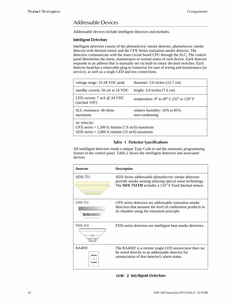
Addressable devices include intelligent detectors and modules.
����������� ������
Intelligent detectors consist of the photoelectric smoke detector, photoelectric smodetector with thermal sensor and the CPX Series ionization smoke detector. The detectors communicate with the main circuit board CPU through the SLC. The conpanel determines the alarm, maintenance or normal status of each device. Each dresponds to an address that is manually set via built-in rotary decimal switches. Edetector head has a removable plug-in connector for ease of wiring and maintenanservice), as well as a single LED and test connections.
����� � ������ �����������
All intelligent detectors sends a unique Type Code to aid the automatic programmfeature in the control panel. Table 2 shows the intelligent detectors and associateddevices
����� � ����������� ������
voltage range: 15-28 VDC peak diameter: 5.0 inches (12.7 cm)
standby current: 50 uA at 24 VDC height: 3.0 inches (7.6 cm)
LED current: 7 mA @ 24 VDC (latched 'ON')
temperature: 0o to 49o C (32o to 120o F
SLC resistance: 40 ohms maximum
relative humidity: 10% to 85% non-condensing
air velocity: CPX series = 1,500 ft./minute (7.6 m/S) maximumSDX series = 3,000 ft./minute (15 m/S) maximum
Detector Description
SDX-751 SDX Series addressable photoelectric smoke detectors provide smoke sensing utilizing optical sense technologyThe SDX-751TH includes a 135o F fixed thermal sensor.
CPX-751 CPX series detectors are addressable ionization smoke detectors that measure the level of combustion products its chamber using the ionization principle.
FDX-551 FDX series detectors are intelligent heat smoke detector
RA400Z The RA400Z is a remote single LED annunciator that canbe wired directly to an addressable detector for annunciation of that detector's alarm status.
16 AFP-100 Instruction PN 51010:A 12/15/98
��������� ������� ���� ����
and er via he s,
nd ss
m
r
e
m
02
AC
et. a
to or
��� ��� ��� ����� ������
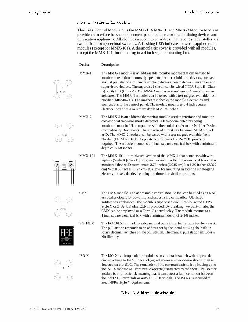
The CMX Control Module plus the MMX-1, MMX-101 and MMX-2 Monitor Modulesprovide an interface between the control panel and conventional initiating devicesnotification appliances. All modules respond to an address that is set by the installtwo built-in rotary decimal switches. A flashing LED indicates power is applied to tmodules (except for MMX-101). A thermoplastic cover is provided with all moduleexcept the MMX-101, for mounting to a 4 inch square mounting box.
����� � ����� ���� ������
Device Description
MMX-1 The MMX-1 module is an addressable monitor module that can be used to monitor conventional normally open contact alarm initiating devices, such asmanual pull stations, four-wire smoke detectors, heat detectors, waterflow asupervisory devices. The supervised circuit can be wired NFPA Style B (ClaB) or Style D (Class A). The MMX-1 module will not support two-wire smoke detectors. The MMX-1 modules can be tested with a test magnet available froNotifier (M02-04-00). The magnet test checks the module electronics and connections to the control panel. The module mounts to a 4 inch square electrical box with a minimum depth of 2-1/8 inches.
MMX-2 The MMX-2 is an addressable monitor module used to interface and monitoconventional two-wire smoke detectors. All two-wire detectors being monitored must be UL compatible with the module (refer to the Notifier DevicCompatibility Document). The supervised circuit can be wired NFPA Style Bor D. The MMX-2 module can be tested with a test magnet available from Notifier (PN M02-04-00). Separate filtered switched 24 VDC power is required. The module mounts to a 4 inch square electrical box with a minimudepth of 2-1/8 inches.
MMX-101 The MMX-101 is a miniature version of the MMX-1 that connects with wire pigtails (Style B [Class B] only) and mount directly in the electrical box of themonitored device. Dimensions of 2.75 inches (6.985 cm) L x 1.30 inches (3.3cm) W x 0.50 inches (1.27 cm) D, allow for mounting in existing single-gangelectrical boxes, the device being monitored or similar locations.
CMX The CMX module is an addressable control module that can be used as an Nor speaker circuit for powering and supervising compatible, UL-listed notification appliances. The module's supervised circuit can be wired NFPA Style Y or Z. A 47K ohm ELR is provided. By breaking two built-in tabs, the CMX can be employed as a Form-C control relay. The module mounts to a 4 inch square electrical box with a minimum depth of 2-1/8 inches.
BG-10LX The BG-10LX is an addressable manual pull station featuring a key-lock resThe pull station responds to an address set by the installer using the built-inrotary decimal switches on the pull station. The manual pull station includes Notifier key.
ISO-X The ISO-X is a loop isolator module is an automatic switch which opens thecircuit voltage to the SLC branch(es) whenever a wire-to-wire short circuit isdetected on that SLC. The remainder of the communications loop leading upthe ISO-X module will continue to operate, unaffected by the short. The isolatmodule is bi-directional, meaning that it can detect a fault condition betweenthe input SLC terminals or output SLC terminals. The ISO-X is required to meet NFPA Style 7 requirements.
AFP-100 Instruction PN 51010:A 12/15/98 17

������� ���� ���� ���������
��������)���+�����������������
Table 1-4 contains descriptions of accessories used with addressable devices:
����� � �� ���� ��� ����� ���� ����
Device Description
EOL Resistor Assembly Notifier PN R-47K
The 47K End-of-Line Resistor Assembly is used to supervise the MMX-1 module and CMX module circuits. The resistor is included with each MMX-1 and CMX module.
EOL Power Supervision Relay The UL-listed End-of-Line Power Supervision Relay is used to supervise the power to four-wire smoke detectors and notification appliances.
N-ELR Mounting Plate The N-ELR is a single End-of-Line resistor plate which is required for use in Canada. An ELR, which is supplied with each module and fire alarm control panel, is mounted to the ELR plate. Resistors mounted to the N-ELR plate can be usedfor the supervision of an MMX-1 and MMX-101 module and CMX module circuit.
18 AFP-100 Instruction PN 51010:A 12/15/98
������� ������� ������� ���� ����
ated
5
wer ing
nts
n.
des
red s are
ter
the
to o the ect a , for
s is on face
��������/�����
The AFP-100 main circuit board includes option module connectors which are locon the right side of the board. Available option modules include the following:
��/0�*�*������������/����
The ACM-8R Relay Control Module contains eight high current (5 amps) Form-C relays. The module interfaces to host fire alarm control panels which employ an EIA-485 communications bus. ACM-8R modules may be connected to the EIA-48bus up to 6,000 feet (1,800 m) away from the host control panel. Power-limited, filtered, nonresettable power must be supplied by the host FACP or a UL-listed posupply such as the FCPS-24. Figure 41, “Wiring the ACM-8R,” on page 60, for wirdetails.
����1����*�/0���*�����/����
The Fire•Lite RTM-8F Relay/Transmitter Module plugs into connector J6 and mouon the bottom right side of the AFP-100 main circuit board. When the module is installed, jumper JP4 must be cut in order to provide module placement supervisioThe Fire•Lite RTM-8F provides eight high current (5 amps) Form-C relays. These relays track software zones 1 through 8. The Relay/Transmitter Module also proviMunicipal Box or Remote Station transmitters. A control panel equipped with an Fire•Lite RTM-8F meets NFPA 72 codes for Auxiliary and Remote Station requirements. In remote station applications, the Fire•Lite RTM-8F can be configuto transmit alarm only or alarm and trouble signals. Disable switches and indicatorprovided on the Fire•Lite RTM-8F module. Refer to Figure 42, “Fire•Lite RTM-8F Module Installation,” on page 61 and Figure 43, “Fire•Lite RTM-8F Relay TransmitModule Components,” on page 62, for additional information.
�-/0',�������2���-��������/����
The Printer/PC Interface Module may be used to permanently connect a printer tocontrol panel for the purpose of printing a history report, walktest file or program listing. Printers require separate primary AC power. The PIM-24 module connectsthe serial EIA-232 port on the printer using cable PN 75267. The module mounts tJ11 connector on the AFP-100 main circuit board. The PIM-24 is also used to conncomputer for upload/download of programming data. Refer to Figure 44 on page 64information on connections and "System Edit" on page 79, for information on programming the control panel for use with a printer or PC.
Note The PIM-24 option cannot be used simultaneously with the DIM-485/LCD-2x20 option.
3���1�����&44�������������������+���������#
You can use the Veri•Fire 100 Upload/Download Software to program the control panel directly from most IBM PC/XT/AT or compatible computers, including laptopand portables, equipped with a serial port. Typically, you program files can also becreated and stored on the PC, then downloaded to the control panel. The softwarefour 3½ inch disks, and requires separate purchase of the PIM-24 Printer/PC InterModule with cable PN 75267 and DB9F/25 connectors PN 46029.
AFP-100 Instruction PN 51010:A 12/15/98 19

������� ���� ���� ������� �������
the
et.
Fire the
5+�����5���������+�#�������� ��� ������2����� ���
The UDACT transmits system status to UL-listed Central Station receivers throughpublic switched telephone network. The UDACT is compact in size and may be mounted inside the host control panel or may mount externally in a separate cabinEIA-485 annunciator communications bus and filtered 24 VDC connections are required. The UDACT transmits 198 points or 56 zones when connected to the AFP-100. Refer to Figure 38 on page 57 and Figure 39, “External UDACT Connections,” on page 58, for wiring details and "System Edit" on page 79, for information on programming the AFP-100 for use with the UDACT.
+-/0,�6�+�������-��������/����
The Display Interface Module is required to connect an LCD-2x20 Series RemoteAnnunciator to the control panel. The DIM-485 plugs into connector J11 located ontop right side of the AFP-100 main circuit board. Refer to “Annunciator Wiring” on page 117, for wiring details and "System Edit" on page 79, for information on programming the control panel for use with the LCD-2x20.
Note The the DIM-485 and LCD-2x20 cannot be used simultaneously with the PIM-24 module.
20 AFP-100 Instruction PN 51010:A 12/15/98
he
lder
eries one
CP ttery hen can the
ard in
�����������
+����������
A gray dress panel (DP-1-R) is available as an option (required for Canadian installations) and included with the AFP-100. The dress panel restricts access to tsystem wiring while allowing access to the membrane panel.
��������7��
The BB-17 battery box may be used to house two 12 AH or 18 AH (required with oor newer backbox) batteries. The battery box mounts directly below the AFP-100 cabinet. The box is red gray and is provided with knockouts.
The BB-55 battery box may be used to house two 25 AH batteries, two 60 AH battor one 100 AH battery. When the CHG-120 is mounted in the BB-55, two 25 AH or 60 AH battery may also be housed in the battery box.
�890&'4��������:��#��
The CHG-120 is capable of charging 25 AH to 120 AH lead-acid batteries with thenewer version of the AFP-100 main circuit board which allows disabling of the FAbattery charger. The batteries and charger can be housed in the Notifier BB-55 BaBox which can be mounted up to 20 feet away from the control panel. Note that wusing the BB-55 for housing the charger and batteries, a maximum 25 AH batterybe accommodated. For larger Amp Hour batteries, use multiple BB-55s. Refer to CHG-120 Manual for additional information.
WARNING: Do not apply AC power or batteries until the system is completely wired and ready for testing. Set the CHG-120 Voltage Select switch (SW1) to match the AC powersource voltage (120VAC or 240 VAC). With the breaker at the main power distribution panel turned off, connect AC power wires to CHG-120 TB1 as shown below.
Wire the CHG-120 to the AFP-100 as shown. You must disable the main circuit bobattery charger when using the CHG-120. Do so by cutting jumper JP1 as shown Figure 3 on page 14.
!
AFP-100 Instruction PN 51010:A 12/15/98 21

������� ���� ���� ����������
T te
r r to ,
d
t and
sets an
with
d ly
last
h ne
����������
��� ����� � !��� �"�� ����������
The ACS Series Annunciators remotely display system status. The ACM/AEM-16Aannunciators display zone alarm and trouble status. In addition, they provide remoAcknowledge, Silence, Reset and Drill functions. The ACM/AEM-32 annunciators display zone alarm status only and provide no remote system switch functions. Fomore detailed information, refer to the appropriate ACM Annunciator manual. Refe“Annunciator Wiring” on page 117, for wiring details and "System Edit" on page 79for information on programming the AFP-100 for annunciator use.
ACM-16AT and AEM-16AT The Annunciator Control Module-16AT contains 16 realarm and 16 yellow trouble LEDs, a System Trouble LED, an On Line/Power LEDand a local piezo sounder with switches for AFP-100 Acknowledge, Silence, ReseDrill. The ACM-16AT will accept up to three AEM-16AT Expanders.
The Annunciator Expander Module-16AT connects to the ACM-16AT and adds 16of red alarm LEDs and yellow trouble LEDs. Three AEM-16ATs may be added to ACM-16AT.
AFM-16AT The Annunciator Fixed Module-16AT contains 16 red alarm and 16 yellow trouble LEDs, a System Trouble LED, an On Line/Power LED and a local sounder with switches for AFP-100 Acknowledge, Silence, Reset and Drill. The AFM-16AT is fixed at address 1 and communication is via the EIA-485 data line.
ACM-32A and AEM-32A The Annunciator Control Module-32A contains 32 red alarm LEDs, a System Trouble LED, an On Line/Power LED and a local sounder a local Silence/Acknowledge switch. The ACM-32A will accept one AEM-32A Expander.
The Annunciator Expander Module-32A connects to the ACM-32A and adds 32 realarm LEDs. The AEM-32A is identical in frontal appearance to the ACM-32A. Onone expander module is allowed.
AFM-32A The Annunciator Fixed Module-32A has 32 red alarm LEDs. Multiple annunciators may be used by setting all annunciators to Receive Only, except theAFM-32A in line. Each annunciator's address is internally fixed at '1', and communication is via the EIA-485 data line. The Local Silence/Acknowledge switcfunctions as local lamp test and silence for annunciator piezo. LEDs include On Liand System Trouble indicators.
AFM-16A The same as the AFM-32A except it has 16 red alarm LEDs.
22 AFP-100 Instruction PN 51010:A 12/15/98
���������� ������� ���� ����
fire
lay
t and
hed
cted r n
LED ee used
em .
k d to he
est emote ther
r 16 nica-he sis
g itch.
di-
s SW1
��+0'7'4��������*� ������������������
Consists of the LCD-2x20 and LCD-2x20L, are compact, 40-character backlit LCDannunciators that are capable of displaying English-language text. The LCD-2x20mimics the display on the control panel and annunciates device type, point alarm,trouble or supervisory condition, zone assignment plus any custom alpha labels programmed into the control panel. They also provide system status LEDs to disppower, alarm, trouble and supervisory conditions. Additionally, the LCD-2x20 is capable of performing critical system functions such as acknowledge, silence, resedrill, remotely from the host control panel.
Communication between the control panel and the LCD-2x20 Series is accomplisover a serial interface employing the EIA-485 communication standard (DIM-485 option module is required). Up to 32 LCD-2x20 Series Annunciators may be conneto the EIA-485 circuit. The annunciators may be powered from the host FACP or aremote UL-listed filtered power supply such as the FCPS-24. Refer to “AnnunciatoWiring” on page 117 for wiring details and "System Edit" on page 79 for informatioon programming the AFP-100 for annunciator use.\
�+/���������� ��+������/��������9���:������������
The LDM Series Lamp Driver Modules, which consist of the LDM-32 master and LDM-E32 expander modules, are used to provide an interface to a custom graphicannunciator. The master module provides power and control for a maximum of threxpander modules. The LDM-32 and LDM-E32 have output connectors which are to drive lamps or LEDs and input connectors which are used for remote switch functions. Refer to the LDM Series Lamp Drive Modules Manual for a complete description. Refer to “Annunciator Wiring” on page 117 for wiring details and "SystEdit" on page 79 for information on programming the AFP-100 for annunciator use
�#� ��$��
The Lamp Drive Module LDM-32 has 32 alarm lamp/LED driver outputs which sincurrent to system common (–) on activation. A single positive (+) voltage is requiresupply total operating power for all lamps or LEDs when all drivers are activated. TLDM-32 provides a separate driver for system trouble and inputs for a local lamp tswitch. A maximum of 16 external control switches may be wired to the LDM-32F.DIP switch SW3 is used to enable or disable the onboard piezo sounder, enable rswitch functions, select a flashing LED function for new alarms and troubles and ofunctions. Switch SW4 is used to configure the module to annunciate 32 alarms oalarms and 16 troubles. A green On Line LED flashes to indicate ongoing commutions with the host FACP. One LDM-32 supports up to three LDM-E32 modules. TLDM-32 is supplied with four standoffs and screws for mounting to a CHS-4L chasor custom backbox.
�#� ��$ ��
Each LDM-E32 expander module provides 32 additional lamp/LED driver outputs from J5, J6, J7 and J8. The expander module has a slide switch, SW4, for selectinalarm only or alarm and trouble annunciation and an input for a local lamp test swIn alarm only mode, use only one LDM-32 and one LDM-E32 for a maximum of 56alarm indicators and 8 system status indicators. In alarm/trouble mode, use one LDM-32 and three LDM-E32Fs for a maximum of 56 alarm indicators, 56 trouble incators, 16 status indicators and 64 optional control switch inputs. Multiple sets of LDM-32Fs with LDM-E32 expanders increase the system annunciation capabilitiebeyond 56 zones or points. This is possible by various settings of address switchesand SW2 on the LDM-32 (refer to Appendix D). Each LDM-E32 is supplied with a 26-conductor expander ribbon cable, four standoffs and screws.
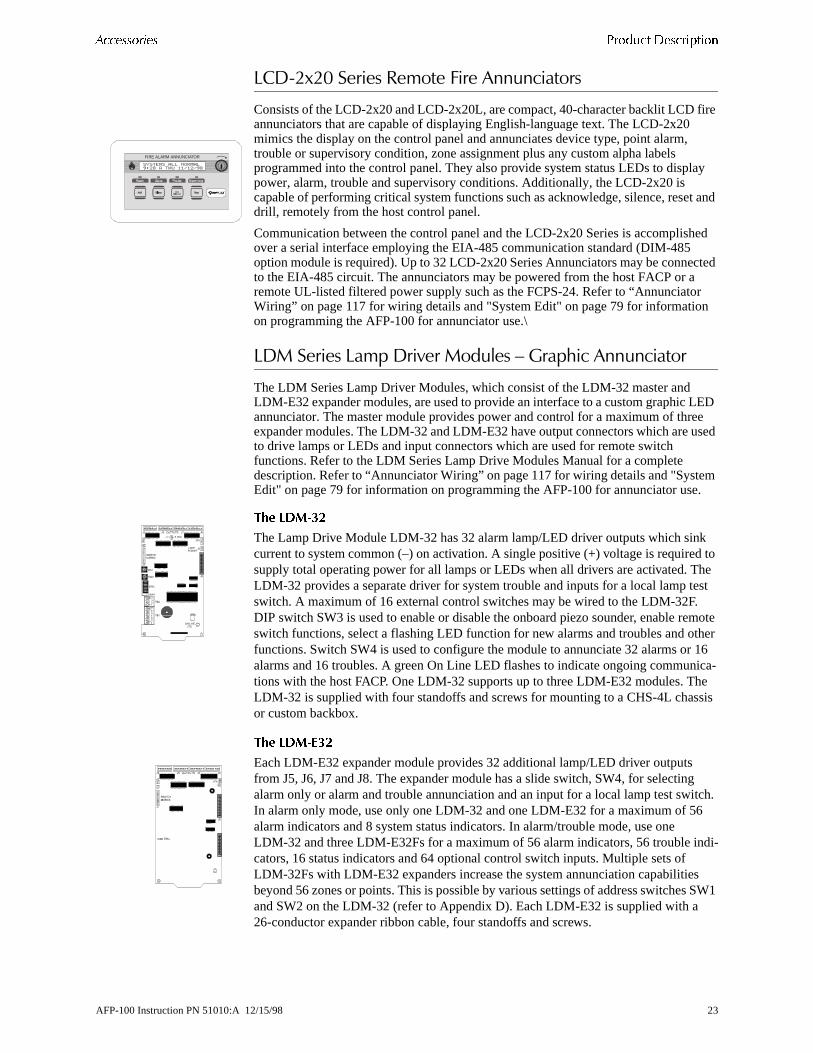
FIRE ALARM ANNUNCIATOR
AFP-100 Instruction PN 51010:A 12/15/98 23

������� ���� ���� ����������
ing may s
for
u can er
re m
des m
AC ut put
for on r, nger ult,
one the ires
n
may FCPS L
����0',�*� ����������:��#��������������
The FCPS-24 is a compact, remote power supply with battery charger for expandsystem power. This remote power supply consists of a filtered 24 VDC output that be configured to drive up to four Notification Appliance Circuits [four Style Y (ClasB) or two Style Z (Class A) and two Style Y (Class B)]. Alternately, the four Notification Appliance Circuits may be used as auxiliary filtered power configured resettable or nonresettable operation.
The FCPS-24 may be used in a number of different applications. For instance, youse the FCPS-24 as a remotely-mounted power supply and battery charger to powfour, coded or noncoded, Notification Appliance Circuits. Alternately, any or all of these circuits may be used as 24 VDC output circuits capable of powering four-wismoke detectors or any device that requires filtered power. These circuits may beconfigured as resettable or nonresettable outputs to expand FACP auxiliary systepower.
One of the most common applications for the FCPS-24 remote power supply incluthe NAC expander mode. In this application, you can connect one or two NACs frothe main control panel NAC output(s) to the remote power supply control Input circuits. When these Control Input circuits activate (due to reverse polarity of the Noutput), the power supply will activate its corresponding outputs. NAC Control Inp#1 controls power supply output circuits 1 and 2. NAC Control Input 2 controls outcircuits 3 and 4.
During the inactive state, the remote power supply supervises its NAC field wiringshort and open circuits. If a fault is detected, the supply will enter a trouble conditiand illuminate the corresponding NAC trouble LED (Output Circuits 1-4). Howeveonce the NACs are activated, the supervision is disabled and the circuits are no losupervised. Supervision of other power supply faults such as low battery, earth faAC loss and battery charger failure will continue and may be monitored via the independent trouble relay contact.
If a specific application requires that all four outputs activate at the same time, onlyNAC control input from the FACP is necessary. For this application, the NAC fromFACP is wired into NAC Control Input #1 of the remote supply and then a pair of ware connected from NAC Control Output #1 to NAC Control Input #2. Refer to the FCPS-24 Installation, Operation and Application Manual for a complete descriptioand examples of applications.
A CMX module, which can be located up to 10,000 feet (3,000 m) from the FACP, be used to activate the FCPS power supply. The module can be powered from theauxiliary 24 VDC power output (TB3 Terminals 8 and 9) and supervised by an EOrelay.
�����"������������(��
4/(� 5� ��� /����� ) �� �
�/ (��
0��"������ ���������/��� �� /���� 6�� � -�"�� 4�/(�
0��"������ ���������/��� �� /���� 6�� � ��"�� 4�/(�
����� 7������ 8 0��"��������������� /��� �� � -. 9�/) �� � ��
����� 7 0��"������ ���������/��� �� � -. 9�/ ) �� � �-
����� 7������ 8 0��"��������������� /��� �� � -. 9�/) �� � �:
����� 7 0��"������ ���������/��� �� � -. 9�/ ) �� � �.
%������ /$�� ��
24 AFP-100 Instruction PN 51010:A 12/15/98
a The n the floor for ce. ll
ions
.
SECTION 2 INSTALLATION
��������
Carefully unpack the system and check for shipping damage. Mount the cabinet inclean, dry, vibration-free area where extreme temperatures are not encountered. area should be readily accessible with sufficient room to easily install and maintaicontrol panel. Locate the top of the cabinet approximately 5 feet (1.5 m) above thewith the hinge mounting on the left. Determine the number of conductors requiredthe devices to be installed. Sufficient knockouts are provided for wiring convenienSelect the appropriate knockout(s) and pull the required conductors into the box. Awiring should be in accordance with the National and/or Local codes for fire alarmsystems.
���;)�7�/����#
1 Mark and predrill holes for the top two keyhole mounting bolts using the dimensshown in Figure 6 on page 26.
2 Install two upper fasteners in the wall with the screw heads protruding.
3 Using the upper “keyholes,” mount the backbox over the two screws.
4 Mark and drill the lower two holes.
5 Secure backbox by installing the remaining fasteners and tightening all screws
AFP-100 Instruction PN 51010:A 12/15/98 25
������������ ������� �������
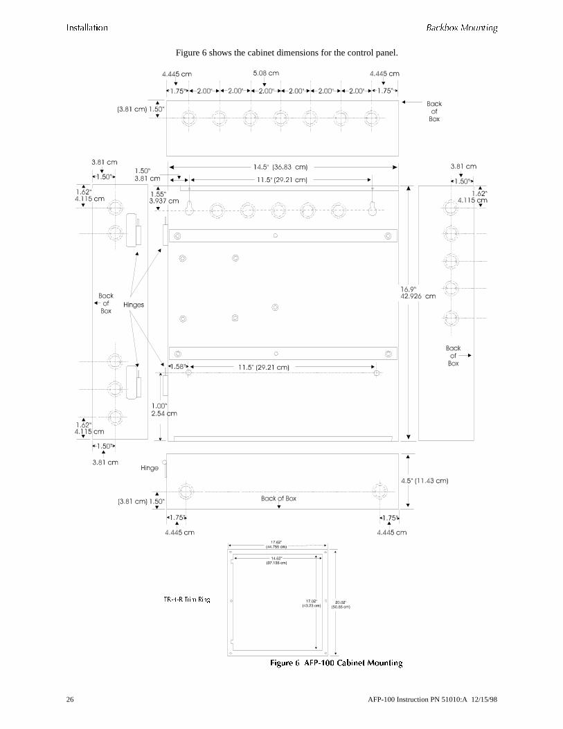
Figure 6 shows the cabinet dimensions for the control panel.
������ � �!"�## ������ ��������
������ ���� ��
26 AFP-100 Instruction PN 51010:A 12/15/98

�������� ����������� ������������
, as
�� ������-���������
1 Ascertain that backbox area is dry and free of construction dust.
2 Mount the transformer(s) to the backbox studs as shown in Figure 7.
3 Using the nuts supplied, secure transformer(s) to studs.
4 Position the Main Circuit Board over the backbox rails, aligning mounting holesshown in Figure 7.
5 Secure in place with four (4) screws. Tighten securely.
6 Plug transformer leads into circuit board connectors:
• Top transformer (supplied) to J17
• Bottom transformer (optional) to J19
Figure 7 shows transformer and main circuit board mounting into backbox.
������ $ ��������� ��������
����������
���
���
AFP-100 Instruction PN 51010:A 12/15/98 27
������������ �� ��� � !�"��
own
e.
the
�������+�������
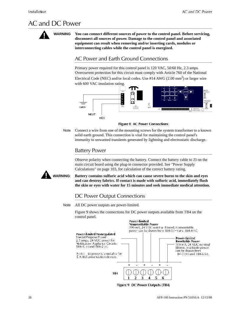
WARNING You can connect different sources of power to the control panel. Before servicing, disconnect all sources of power. Damage to the control panel and associated equipment can result when removing and/or inserting cards, modules or interconnecting cables while the control panel is energized.
�������������.��:�9���������������
Primary power required for this control panel is 120 VAC, 50/60 Hz, 2.3 amps. Overcurrent protection for this circuit must comply with Article 760 of the National
Electrical Code (NEC) and/or local codes. Use #14 AWG (2.00 mm2) or larger wire with 600 VAC insulation rating.
������ % � !�&�� �����������
Note Connect a wire from one of the mounting screws for the system transformer to a knsolid earth ground. This connection is vital for maintaining the control panel's immunity to unwanted transients generated by lightning and electrostatic discharg
�����������
Observe polarity when connecting the battery. Connect the battery cable to J3 on main circuit board using the plug-in connector provided. See "Power Supply Calculations" on page 103, for calculation of the correct battery rating.
WARNING: Battery contains sulfuric acid which can cause severe burns to the skin and eyes and can destroy fabrics. If contact is made with sulfuric acid, immediately flush the skin or eyes with water for 15 minutes and seek immediate medical attention.
+���������������������
Note All DC power outputs are power-limited.
Figure 9 shows the connections for DC power outputs available from TB4 on the control panel.
������ ' (� !�&�� )������ *���+
!
���
����
��
!
���������� ���������������� ( ���� (��-;2 ����# -. 9�/ ��� "�0��"������ ��������� /��� ���;5%.,��<� ��� 5%.,- �=�;
1 2 3 4 5 6
+ - + - + -
������������������� ���:!! ��# -. 9�/ ������ "�������# ��������������� ��� �� ���� "�� 5%.,: �<� ��� 5%.,. �=�;
����������������� ���:!! ��# -. 9�/ ������"�������# ���������� ������ �� ���� "��5%.,2 �<� ��� 5%.,> �=�;0��� 5$�� ��� �� �� ������ "�
&6�,.32 ��� ������� ��?����;
���
28 AFP-100 Instruction PN 51010:A 12/15/98

�������� #����� $��%& ������������
or sory
nch
��������*���������"
The AFP-100 provides a set of Form-C alarm and Form-C trouble contacts rated f2.0 amps @ 30 VDC (resistive). The control panel also provides a Form-A supervicontact rated for 2.0 amps @ 30 VDC (resistive). Refer to Figure 10 forUL power-limited wiring requirements.
Note Relay connections may be power-limited or nonpower-limited, provided that 0.25 ispacing is maintained between conductors of power-limited and nonpower-limitedcircuits.
������ �# ,� � ����������� *���+
1 2 3 4 5 6 7 8���
SUPV ALARM TROUBLENO C NO NC C NO NC C
�� �� ���� ������������� ���������������� ���� ���� ������� ��� ������� ������������������� ���������������� ���� ����
����� �� ������ ��� ��� �� ����������������� ���� ����� � ������ ����� �� ����������� �� ������� �� �� ������������������
!����"������
!����"������
AFP-100 Instruction PN 51010:A 12/15/98 29
������������ '�������� �������� ������
wn sted fer
n uit
d t.
%��������������������������
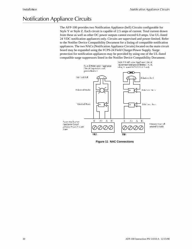
The AFP-100 provides two Notification Appliance (bell) Circuits configurable for Style Y or Style Z. Each circuit is capable of 2.5 amps of current. Total current drafrom these as well as other DC power outputs cannot exceed 6.0 amps. Use UL-li24 VDC notification appliances only. Circuits are supervised and power-limited. Reto the Notifier Device Compatibility Document for a listing of compatible notificatioappliances. The two NACs (Notification Appliance Circuits) located on the main circboard may be expanded using the FCPS-24 Field Charger/Power Supply. Surge protection for notification appliances may be provided by using one of the UL-listecompatible surge suppressors listed in the Notifier Device Compatibility Documen
Figure 11 NAC Connections
#$ %$ %� #� #$ %$ %� #�
���
& ��� "��� ��� ��� ���� ���
����� ����������� ���� ������ ������ ����� �� ����������
+
+ -
+
+ -
+
!�����'�� (��
!�����'�� (��
!�����'�� (��
!�����'�� )�����
!�����'�� #��� !�����'�� #���
)���� * ����������� %�������+��� �� ,� �������� ���������������-
)���� . ����������� %������� +��� ��,� �������� �� ������������� � ��/0���� 1 ���� !� /2343 5"�������-
��
30 AFP-100 Instruction PN 51010:A 12/15/98

(� !�"��)���� *��� #�+������� ������������
) it
5�������0�� ����<����#�*�=��� ���
9�������5�������0�� ����<����#�*�=��� ���
Power-limited and nonpower-limited circuit wiring must remain separated in the cabinet. All power-limited circuit wiring must remain at least 0.25 inches (6.35 mmaway from any nonpower-limited circuit wiring. Furthermore, all power-limited circuwiring and nonpower-limited circuit wiring must enter and exit the cabinet through different knockouts and/or conduits. A typical wiring diagram for the AFP-100 is shown in Figure 12.
������ �- ����� ./ !�&��" ������ 0����� ,�1���������
!������������ +��� ��� !������������ +��� ������������������ +��� ���
!������������+��� ���
���������������+��� ���
%+ !��������� ���� � �� � �� ����������������� ����������� �� � � ��������6 � �� ��
AFP-100 Instruction PN 51010:A 12/15/98 31

������������ (� !�"��)���� *��� #�+�������
are
����1����*�/0���5�������0�� ����<����#�*�=��� ���
Nonpower-limited and power-limited wiring must have a minimum distance of 0.25 inches wire-to-wire. If this module is used to drive nonpower-limited and power-limited circuits, follow the instructions below:
1. Skip a set of dry contacts to maintain the 0.25 inches required space betweenpower-limited and nonpower-limited circuits.
2. If this module is needed to drive power-limited and nonpower-limited relays thatnext to each other, make no connection to the Normally Open contact which separates the two groups of relays. Refer to the wiring diagram in Figure 13.
Note Refer to "Fire•Lite RTM-8F Option Module Installation" on page 61, for additional information on the Fire•Lite RTM-8F.
������ �� ����2/��� ,��"%� ./ 0�����
!������������ +��� ��
��������������� +��� ��
��������������� +��� ��
�� �������
!������������ +��� ��
!������������ +��� ��
!������������ +��� ��
��������������� +��� ��
��������������� +��� ��
��������������� +��� ��
32 AFP-100 Instruction PN 51010:A 12/15/98
*��� �,� ������� ��� ����� $��-& ������������
es
t.
all
from t of are
, ure
r
and
itional les.
<����#�:����#�����#���������������$
��������
The AFP-100 communicates with addressable initiating, monitor and control devicthrough a Signaling Line Circuit (SLC). You can wire the SLC to meet the followingNFPA requirements:
• Style 4 (see Figure 18 on page 37)
• Style 6 (Figure 19 on page 39)
• Style 7 (Figure 20 on page 40)
Notes Note the following when wiring the SLC:
Surge protection for the SLC may be provided by using one of the UL-listed compatible surge suppressors listed in the Notifier Device Compatibility DocumenThe SLC is allowed to leave the building only with the use of a UL-listed surge suppressor found in the Notifier Device Compatibility Document.
Setting detector and module addresses Make sure to change the decade wheels on detectors and modules from the factory setting of “00.” For instructions for setting decade addresses, refer to Figure 25 on page 42.
����+������
You can connect the following devices on the SLC:
��%$� ������
ISO-X Modules permit a zone of detectors and modules to be electrically 'isolated' the remainder of the SLC, allowing critical SLC components to function in the evena short circuit on the SLC wiring (see Figure 18, Figure 19 and Figure 20). These required to meet the requirements of NFPA Style 7.
��� ����� ������
Addressable Monitor Modules allow the control panel to monitor entire circuits of conventional normally-open contacts, alarm initiating devices, manual pull stationsfour-wire smoke detectors, heat detectors, waterflow, supervisory devices (see Fig28 and Figure 29) and conventional detectors (see Figure 30 and Figure 31). The BG-10LX is an addressable manual pull station which contains a miniature monitomodule providing point annunciation (see Figure 18, Figure 19 and Figure 20).
��� ����� ������ Through addressable Control Modules, the control panel can selectively activate Notification Appliance Circuits or Form-C output relays (see Figure 32 on page 49Figure 33 on page 51).
����������� ������ Through the SLC, the control panel communicates with addressable ionization, photoelectric and photoelectric/thermal detectors (see Figure 36 on page 54).
���� ������"The capacity of each AFP-100 includes up to 99 addressable detectors and an addcombination of up to 99 addressable pull stations, CMX modules, and MMX moduIn addition, the control panel supports two NACs.
AFP-100 Instruction PN 51010:A 12/15/98 33

������������ *��� �,� ������� ��� ����� $��-&
for
tal trated ,000
sure . s.
xceed
Note Refer to Appendix A and the installation drawings supplied with each SLC device rating and specifications.
�����,�<����#������0�����#
T-tapping of the SLC wiring is allowed for two-wire (Style 4) configurations. The toresistance of any branch cannot exceed 40 ohms. Measure the resistance as illusbelow. The total wire length of all combined branches cannot exceed 10,000 feet (3m).
8������������������:�*��������
With power removed, short the termination point of one branch at a time and meathe DC resistance from the beginning of the SLC to the end of that particular branchThe total resistance from control panel to each branch end cannot exceed 40 ohmRepeat this procedure for all remaining branches.
������ �� �������� ,�������� �� �&�"0��� /�
For Each SLC, Add the lengths of all the branches on one SLC. This sum cannot e10,000 feet (3,000 m) using 12 AWG (3.25 mm2) twisted, shielded wire.
����� & ��� '�����(���
Single Open on SLC
Single Ground on SLC
Shorted SLC
SLC Shorted and Opened
SLC Shorted and Grounded
SLC Opened and Grounded
Communications Loss
Style 4 (two-wire) SLC Operation (meets NFPA 72 Style 4 requirements)
Trouble Alarm Capability and Trouble
Trouble Trouble Trouble Trouble Trouble
Style 6 (four-wire) SLC Operation (meets NFPA 72 Style 6 requirements)
Alarm Capability and Trouble
Alarm Capability and Trouble
Trouble Trouble Trouble Alarm Capability and Trouble
Trouble
Style 7 (four-wire) SLC Operation (meets NFPA Style 7 requirements)
Alarm Capability and Trouble
Alarm Capability and Trouble
Alarm Capability and Trouble
Trouble Alarm Capability and Trouble
Alarm Capability and Trouble
Trouble
Trouble indicates that a trouble signal will be generated at the control panel during the abnormal condition
Alarm Capability indicates an alarm signal can be transmitted to the control panel during the abnormal condition.
SLC operation meeting Style 7 requirements isolates entire physical zone on the SLC from faults that occur within other areas of the SLC.
)"+ 7 �
#����
34 AFP-100 Instruction PN 51010:A 12/15/98
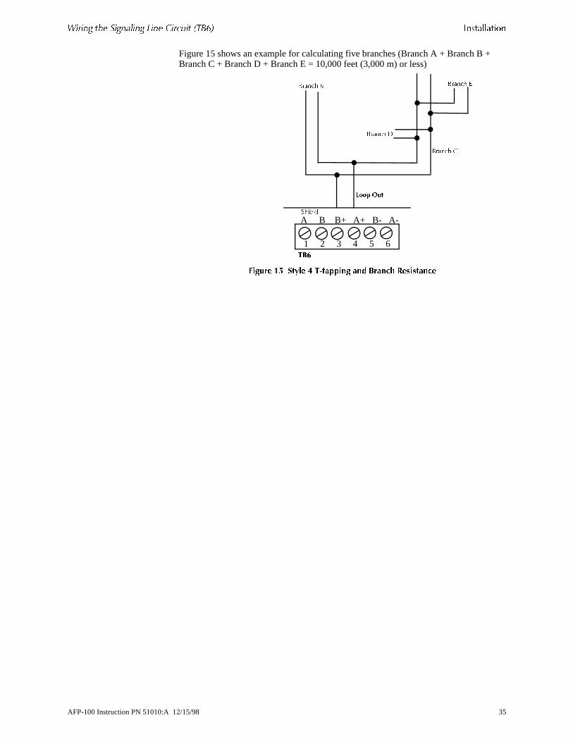
*��� �,� ������� ��� ����� $��-& ������������
Figure 15 shows an example for calculating five branches (Branch A + Branch B +Branch C + Branch D + Branch E = 10,000 feet (3,000 m) or less)������ �� �� � � �"������ �� ����3 ,��������
1 2 3 4 5 6��!
A B B+ A+ B- A-)�����
#���� +
#���� &
#���� 8#���� #
��� ��
AFP-100 Instruction PN 51010:A 12/15/98 35

������������ *��� �,� ������� ��� ����� $��-&
ot
WG
�����$�<����#
T-tapping of the SLC wiring is not allowed for Style 6 configuration. The total resistance of the complete wire run cannot exceed 40 ohms and total length cannexceed 10,000 feet (3,000 m).
• Total length of the SLC cannot exceed 10,000 feet (3,000 m) using 12 A(3.25 mm2) wire.
• DC Resistance of the SLC pair cannot exceed 40 ohms.
/������#�*������������:�����
With power removed, do the following:
1. Disconnect SLC Out and SLC Return at the control panel.
2. Short the two leads of SLC Retupn and c`nnect tbe meter to SLC Out.
3. Measure the resistance as shown in Figure 16.
������ �� �������� ,�������� ��� ����"0��� /�
.
������ �$ �� � � 0����� ,�1���������
�@/ ) �
�@/ ��� ��
1 2 3 4 5 6��!
A B B+ A+ B- A-)�����
�� �������� ��
�� ���������
%< ��� %, A ) �� � �@/�< ��� �, A ��� �� �@/
36 AFP-100 Instruction PN 51010:A 12/15/98
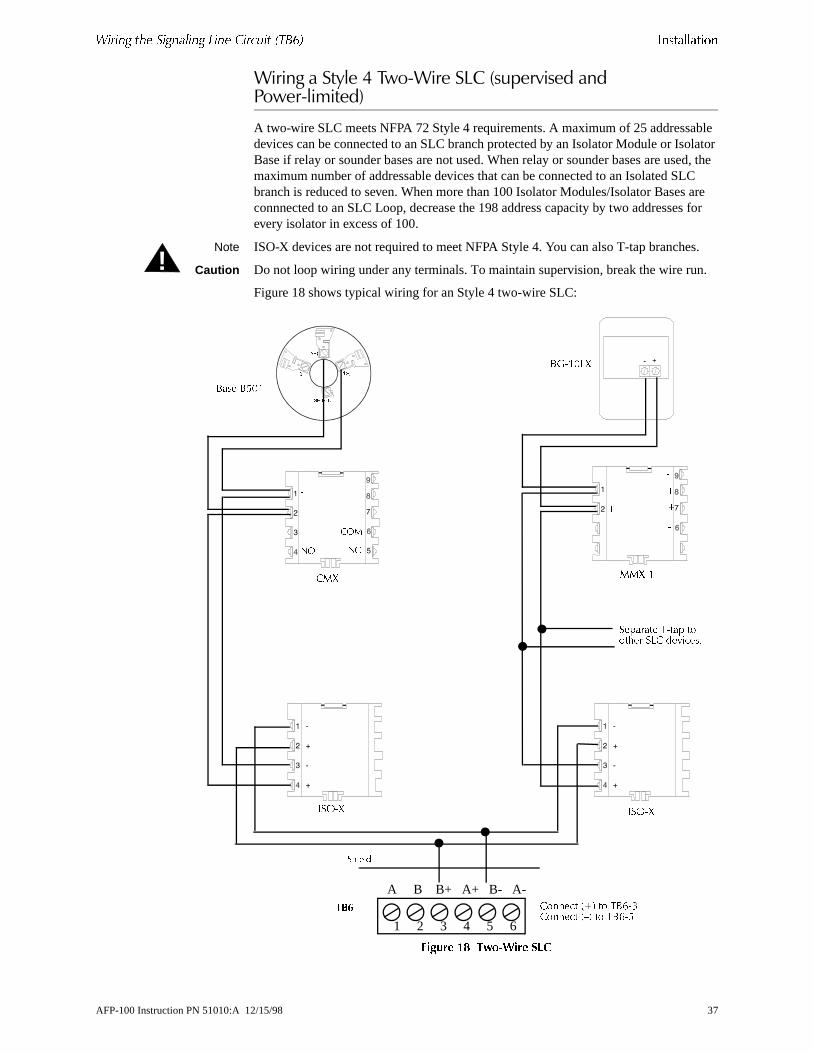
*��� �,� ������� ��� ����� $��-& ������������
ble olator ed, the C
are s for
s.
n.
<����#��������,����0<����������������������������0�� ���
A two-wire SLC meets NFPA 72 Style 4 requirements. A maximum of 25 addressadevices can be connected to an SLC branch protected by an Isolator Module or IsBase if relay or sounder bases are not used. When relay or sounder bases are usmaximum number of addressable devices that can be connected to an Isolated SLbranch is reduced to seven. When more than 100 Isolator Modules/Isolator Basesconnnected to an SLC Loop, decrease the 198 address capacity by two addresseevery isolator in excess of 100.
Note ISO-X devices are not required to meet NFPA Style 4. You can also T-tap branche
Caution Do not loop wiring under any terminals. To maintain supervision, break the wire ru
Figure 18 shows typical wiring for an Style 4 two-wire SLC:
������ �% �&�"0��� /�
!
1 2 3 4 5 6
��!
A B B+ A+ B- A-
)�����
/����� �<� � 5%>,:/����� �=� � 5%>,2
%B,�!@*
%��� %2!�
/+* ++*,�
6�),*6�),*
�������� 5,��� ��$�� �@/ ��?����;
�
$
�
$
$
�
�
$
�7 �+
+79
����
����
�
���
AFP-100 Instruction PN 51010:A 12/15/98 37

������������ *��� �,� ������� ��� ����� $��-&
nder ted to s/
ty by
n.
�����$����0<����������������������������0�� ���
The four-wire SLC meets NFPA 72 Style 6 requirements. A maximum of 25 addressable devices can be connected to an SLC branch protected by an IsolatorModule or Isolator Base if relay or sounder bases are not used. When relay or soubases are used, the maximum number of addressable devices that can be connecan Isolated SLC branch is reduced to seven. When more than 100 Isolator ModuleIsolator Bases are connnected to an SLC Loop, decrease the 198 address capacitwo addresses for every isolator in excess of 100.
Note: You cannot T-tap a Style 6 SLC.
Caution Do not loop wiring under any terminals. To maintain supervision, break the wire ru
Figure 19 shows typical wiring for an Style 6 four-wire SLC:
!
1 2 3 4 5 6
TB6
A B B+ A+ B- A-)�����
/����� �@/ ) � � 5%>,: �<� ��� 5%>,2 �=�/����� �@/ ��� �� � 5%>,. �<� ��� 5%>,> �=�
%B,�!@*%��� %2!�
/+* ++*,�
6�),*6�),*
0��� 6�),* ��?���� ��� ����C ���� � ���� 04(������ >;
�
$
$
$
�
�
$
�
�7 �+
+79
����
����
�
���
38 AFP-100 Instruction PN 51010:A 12/15/98

*��� �,� ������� ��� ����� $��-& ������������
vice t nes
01 n. ble same
8
������ �' ����"0��� /�
�����>����0<����������������������������0�� ���
The four-wire SLC meets NFPA 72 Style 7 requirements. By flanking each SLC dewith a pair of ISO-X modules, each device is protected from short circuit faults thamay occur on other SLC devices. For example, a fault on zone 02 will not affect zo01 and 03. The ISO-X modules on either side of Zone 02 will open the SLC. Zonewill still operate from power on SLC Out and Zone 03 will operate from SLC ReturBecause the AFP-100 will no longer be able to communicate with Zone 02, a trousignal(s) will be generated for that device. The ratings and characteristics are the as for a four-wire circuit meeting NFPA Style 6 requirements. When more than 100Isolator Modules/Isolator Bases are connnected to an SLC Loop, decrease the 19address capacity by two addresses for every isolator in excess of 100.
Note No T-tapping or branching is allowed on this circuit.
1 2 3 4
9 8 7 6 5
�����
1 2 3 4
9 8 7 6 5
�����
1 2 3 4
9 8 7 6 5
�����
1 2 3 4
9 8 7 6 5
�����
1 2 3 4
9 8 7 6 5
�����
1 2 3 4
9 8 7 6 5
�����
� � �� �� �� ��
� �
� � � �
� �
� �
� �
� �
� � � �
� �
� �
� �
��� �
���
�
���
�������
������
����
� ����
����
� ����
����
� ����
����
� ����
����
� ����
����
� ����
�������
������
"#$�%&�' � �� �� ���� ���� ��� ���������; %���� ���� � � �������� � ���?����;
/����� �@/ ) � � %< ��� %=/����� �@/ ��� �� � �< ��� �=
���
0��� 5����������� ������ ��� �$�"� ��� 6�),* �� ���;
AFP-100 Instruction PN 51010:A 12/15/98 39
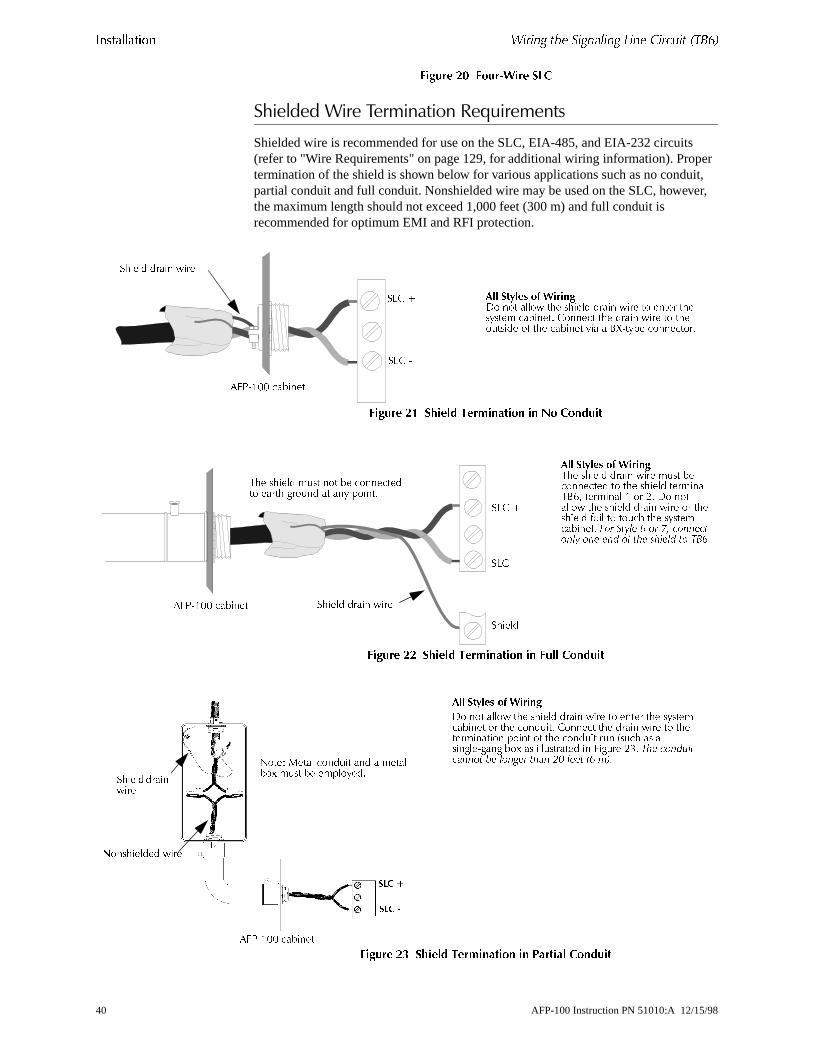
������������ *��� �,� ������� ��� ����� $��-&
er it, er,
������ -# ����"0��� /�
�:�������<������� �������*�=��� ���
Shielded wire is recommended for use on the SLC, EIA-485, and EIA-232 circuits(refer to "Wire Requirements" on page 129, for additional wiring information). Proptermination of the shield is shown below for various applications such as no condupartial conduit and full conduit. Nonshielded wire may be used on the SLC, howevthe maximum length should not exceed 1,000 feet (300 m) and full conduit is recommended for optimum EMI and RFI protection.
������ -� 3�� � ���������� �� �� �������
������ -- 3�� � ���������� �� �� �������
������ -� 3�� � ���������� �� !��� �������
�$���� ����� ���
�4(,�!! �������
�@/ (
�@/ �
#�� ��)�� �* +����� �� ��� �$� �$���� ����� ��� � ����� �$������� �������; /����� �$� ����� ��� � �$� ����� " �$� ������� ?�� � %*,���� �������;
�4(,�!! ������� �$���� ����� ���
5$� �$���� � �� �� �� ��������� ����$ � �� �� ��� ����;
�@/ ,
�$����
#�� ��)�� �* +����5$� �$���� ����� ��� � �� ���������� � �$� �$���� ��������5%># �������� � � -; � ����� �$� �$���� ����� ��� � �$��$���� "�� � � �$ �$� �������������; ��� ���� �� �� ��� ����� �� �� �� �� ����� �� ���
�@/ (
�4(,�!! �������
�� �
�� �
0��$������ ���
0��� +���� ��� �� ��� � ������D � �� �� �������;
#�� ��)�� �* +����
� �� ��� �$� �$���� ����� ��� � ����� �$� ������������� � �$� ��� ��; /����� �$� ����� ��� � �$����������� ���� " �$� ��� �� � � �� �$ �� ���� ��, �� �D �� ��� ������� �� 4� �� -:; �� ������ ����� � ����� ���� �� �� � ���
�$���� ��������
40 AFP-100 Instruction PN 51010:A 12/15/98

�,� ���). ������ ������������
her C is her faulty
ved, A ire
on
eting am
ted -X ing
�:��-��0?�/����
������
The ISO-X module is used to protect critical elements of the SLC from faults on otbranches or sections of the SLC. The ISO-X module continuously monitors the SLconnected to terminal 1(–), 3 (–), 2 (+) and 4 (+). Upon power-up, an integral relaylatched on. The ISO-X periodically pulses the coil of this relay. A short circuit on eitside of the SLC resets the relay. The ISO-X senses the short and disconnects thebranch by opening the positive side of the SLC (terminal 2 or 4). This effectively isolates the shorted branch from the remainder of the SLC. Once the fault is remothe ISO-X automatically reapplies power to the SLC branch. Figure 18, “Two-WireSLC,” on page 37, illustrates the use of an ISO-X on a two-wire SLC meeting NFPStyle 4 requirements. Figure 20, “Four-Wire SLC,” on page 40, illustrates a four-w
SLC meeting NFPA Style 7 requirements.
Note During a fault condition, the AFP-100 will register a trouble for each device isolatedthe SLC branch.
<����#����-��0?�/����
In Figure 24, a short on any T-tapped branch off an ISO-X module on the SLC meNFPA Style 4 wiring requirements, is isolated from all devices installed both upstreof the ISO-X module (SLC In) and on the continuation of the SLC (shown as a dotline). For example, if a short occurs on Branch A of the first ISO-X shown, the ISOmodule would disconnect Branch A and its devices from the rest of the SLC, allowall devices connected before and after that ISO-X module to operate normally.
������ -� 4�� ���� �&�"0��� /��
�@/ 6� �<�
�@/ ) � �<��@/ ) � �=�
�@/ 6� �=�6�),*
6�),* 6�),*
%����$ %%����$ �
�@/ 6�
/���� ���� " �$� �@/
5,������ %����$�� "" " �$� �@/
AFP-100 Instruction PN 51010:A 12/15/98 41

������������ �,� ���). ������
set g the e and
n can he ure
n the
B
nated
9(–
ont is
8����������/������������
MMX and CMX modules provide two rotary decimal switches that you can use to the SLC address of the module. Addresses from 01 to 99 may be set by positioninleft rotary switch to the value of the '10s' digit and the right switch to the value of th'1s' digit. For example, in Figure 25, address 31 is set by turning the left switch to 3turning the right switch to 1.
������ -� ���� � ��������� &���3��
�:��//?0&�/������/����
The MMX-1 Monitor Module is an addressable module that monitors normally-opecontacts and shorting-type alarm initiating devices. The supervised module circuitsbe wired as NFPA Style B or Style D Initiating Device Circuits. There is no limit to tnumber of contact-type devices installed on a monitor module circuit. Refer to Fig28, “Style B Circuit using an MMX-1 Module,” on page 45 and Figure 29, “Style D IDC using an MMX-1 Module,” on page 46, for wiring diagrams.
��� ��������� Connect the AFP-100 SLC to MMX-1 terminals 1 (–) and 2 (+). The MMX-1 occupies one module address on the SLC. Use the rotary switches oMMX-1 to set the module to the required SLC address.
)*'� ��"�� + ���������� ���� ������ Connect the normally-open contacts of the alarm initiating devices to a single two-wire circuit as illustrated in Figure 28, “StyleCircuit using an MMX-1 Module,” on page 45. Connect the circuit to MMX-1 terminals 6(–) and 7(+).
Note A Style B circuit cannot be T-tapped or branched in any manner and must be termiacross the last device by a UL-listed ELR.
)*'� ��"�� ���������� ���� ������ Connect the alarm initiating devices to a single four-wire circuit as illustrated in Figure 29, “Style D IDC using an MMX-1 Module,” on page 46. Connect the four-wire circuit to MMX-1 terminals 6(–) and ), then 7(+) and 8(+).
Note A Style D circuit cannot be T-tapped or branched in any manner.
�� � �,��# The MMX-1 includes a magnetic test switch located near the center frof the module (shown in Figure 27, “MMX-2 Module,” on page 44). Activation of thswitch will cause an open circuit indication in the Style B and Style D SLC.
�@/ ������� ��� � E:�F�!G� �� ��
�G� �� ��
42 AFP-100 Instruction PN 51010:A 12/15/98

�,� ���). ������ ������������
ly er
um
s
<����#�//?0&4&�/������/�����
The MMX-101 module is an addressable module that is functionally and electricalidentical to an MMX-1 Monitor Module (Style B circuits only), but offered in a smallpackage for mounting directly in the electrical box of the contact-type device beingmonitored.
������ -� ��5"�#� ���� �
MMX-1 and MMX-101 modules incorporate the following features:
1. The Initiating Device Circuit is supervised and current-limited to 230 uA @ 24 VDC (nominal).
2. The Initiating Device Circuit wiring may be up to 2,500 feet (760 m) or a maximof 40 ohms for the MMX-1 and 20 ohms for the MMX-101.
3. The Initiating Device Circuit provides the following services (DO NOT MIX):Fire Alarm ServiceAutomatic/Manual Waterflow Alarm Service with normally-open contact deviceSprinkler Supervision with normally-open contact devices
4. The maximum SLC resistance, due to wiring, is 40 ohms.
��� �$� �@/ ������� �� ��� ��$�$��� ����$��; 5$� �@/������� �� �$� "���� ��"� ��E!!F $��$ � �� �� �$�� ��;
�@/ �=��������
�@/ �<������
6�/ �=�������
6�/ �<��?�����
���# ��)� � %��������� ,���"�����
5�������� ��$ � .1H $�# I ���&@� �0,&@� �� /������;
�!G� �� ��
�G� �� ��
AFP-100 Instruction PN 51010:A 12/15/98 43

������������ �,� ���). ������
rs
uired
r t
n -18
d
<����#�//?0'�/������/�����
The MMX-2 Monitor Module is an addressable module that interfaces and monitoUL compatible conventional two-wire smoke detectors. Refer to the Notifier DeviceCompatibility Document. The supervised circuit may be wired as NFPA Style B orStyle D.
��� ��������� Connect the AFP-100 SLC to MMX-2 terminals 1 (–) and 2 (+). The MMX-2 occupies one module address on the SLC. To set a module to the reqSLC address, use rotary switches on the MMX-2 as shown in Figure 25, “Module Addressing Switches,” on page 42.
'�,�� ��������� �� � �,��# The MMX-2 includes a magnetic test switch sensolocated near the center front of the module. Activation of this switch by test magnePN M02-04-00 will cause an open circuit indication in the Style B/D SLC.
)*'� ��"�� + ���������� ���� ������ Connect two-wire smoke detectors to MMX-2 terminals 6 (B-) and 7 (B+) as illustrated in Figure 30, “Style B IDC using aMMX-2 Module,” on page 47. IDC installation wiring must not exceed 25 ohms, 12
AWG (0.75 - 3.25 mm2) wire. Use a 3.9K ohm ELR across the last initiating device.
)*'� ��"�� ���������� ���� ������ Connect two-wire smoke detectors to MMX-2 terminals 6 (B-) and 9 (D-), 7 (B+) and 8 (D+) as illustrated in Figure 31, “Style D Circuit using MMX-2,” on page 48. IDC installation wiring must not excee
25 ohms, 12-18 AWG (0.75 - 3.25 mm2) wire.
MMX-2 Monitor Module Notes
1. IDC and power connections are supervised by the MMX-2 and reported to theAFP-100.
2. Maximum current in alarm is 90 mA power-limited.
3. See "Power Supply Calculations" on page 103, for power supply calculations.
������ -$ ��5"- ���� �
���� � @&�
����� ������ ������� ����$��
+� ��� 5��� (�����
44 AFP-100 Instruction PN 51010:A 12/15/98

�,� ���). ������ ������������
n.
<����#����������-+����:�//?0&�/�����
The NFPA Style B IDC (Initiating Device Circuit), using an MMX-1 module, is supervised and power-limited. Figure 28 shows typical wiring for a Style B IDC:
Caution Do not loop wiring under any terminals. To maintain supervision, break the wire ru
������ -% �� � � ������� ����� � ��5"� ���� �
!
1 2 3 4 5 6
TB6
A B B+ A+ B- A-)�����
1 2 3 4 5 6
TB4
+ - + - + - #��� --
�@/ �<� 5%>,:�@/ �=� 5%>,2
-. 9�/ �<� 5%.,2-. 9�/ �=� 5%.,>
+
+ -
-
+
+ -
-
+
+ -
- +
+ -
-
../�
5 �$� ��D� ��?��� � �$� �@/
+ -
������� &� �� )"+ ���� ��� �� ��������� #��� ����� �� ������ � ������������������� -. 9�/
" �,��� ����������� ����:!! �� ��D;�
J��� �������
+�� �� ( ��������
K@,������ (�� � ���?��������� �� �� �� ���� �� ������?��� � �@/ �� �$��;
-. 9�/ " �,��� ���� �������
&��,",@��� �������.1H $�# I ��� ��������0,&@� �� /������
SLC Out
�
$
$
$
�
�
AFP-100 Instruction PN 51010:A 12/15/98 45

������������ �,� ���). ������
n.
<����#��������+�-+����:�//?0&�/�����
The Style D IDC (Initiating Device Circuit), using an MMX-1 module, is supervisedand power-limited.
Note An ELR is not required when wiring Style D (Class A).
Caution Do not loop wiring under any terminals. To maintain supervision, break the wire ru
������ -' �� � ( 4(� ����� � ��5"� ���� �
!
1 2 3 4 5 6��!
A B B+ A+ B- A-)�����
1 2 3 4 5 6���
+ - + - + - #��� --
�@/ �<� 5%>,:�@/ �=� 5%>,2
-. 9�/ �<� 5%.,2-. 9�/ �=� 5%.,>
+
+ -
-
+
+ -
-
+
+ -
- +
+ -
-
../�
5 �$� ��D� ��?��� � �$� �@/
+ -
"#$�%&�'� �� �@/ ���� ���� ������������; %���� ��� � � � ��������� ���?����;���������� -. 9�/
" �,��� ����������� ����:!! �� ��D;�
J����������
K@,������ (�� � ���?��������� �� �� �� ���� �� ������?��� � �@/ �� �$��;
-. 9�/" �,��������������
+�� �� ( ��������
�@/ ) �
��� ���
�
�
$
$
$
�
46 AFP-100 Instruction PN 51010:A 12/15/98

�,� ���). ������ ������������
n.
<����#����������-+����:�//?0'�/�����
The NFPA Style B IDC (Initiating Device Circuit) is supervised and power-limited.
Caution Do not loop wiring under any terminals. To maintain supervision, break the wire ru
������ �# �� � � 4(� ����� � ��5"- ���� �
!
1 2 3 4 5 6
A B B+ A+ B- A-)�����
1 2 3 4 5 6
+ - + - + -#��� --
�@/ �<� 5%>,:�@/ �=� 5%>,2
-. 9�/ �<� 5%.,2-. 9�/ �=� 5%.,>
+
+ -
-
++*,-
5 �$� ��D���?��� � �$��@/
+ -
"������' � �� �@/ ���� ���� ������������; %���� ��� � � � ��������� ���?����;
���������� -. 9�/" �,��� ����������� ����:!! �� ��D;�
K@,������ /������������ �������
&��,",@��� �������:;�H $� ����� ����
+
+ -
-
+
+ -
-
K@,������ /������������ �������
K@,������ /������������ �������
�@/ ) �
�
�
� �
$
$
$
$
:
�
��!���
AFP-100 Instruction PN 51010:A 12/15/98 47
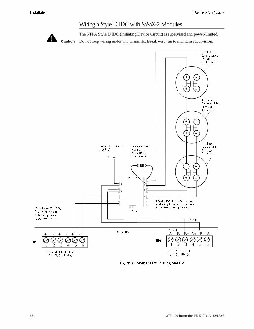
������������ �,� ���). ������
<����#��������+�-+����:�//?0'�/�����
The NFPA Style D IDC (Initiating Device Circuit) is supervised and power-limited.
Caution Do not loop wiring under any terminals. Break wire run to maintain supervision.
������ �� �� � ( ������� ����� ��5"-
!
1 2 3 4 5 6
A B B+ A+ B- A-)�����
1 2 3 4 5 6
+ - + - + -#��� --
�@/ �<� 5%>,:�@/ �=� 5%>,2
-. 9�/ �<� 5%.,2-. 9�/ �=� 5%.,>
+
+ -
-
++*,-
5 ��D� ��?��� ��$� �@/
+ -
������� &� �� )"+ ���� ��� �� ��������� #��� ����� �� ������ � ������������������� -. 9�/
" �,��� ����������� ����:!! �� ��D;�
+
+ -
-
+
+ -
-
K@,������/�������������������
�@/ ) �
K@,������/�������������������
K@,������/�������������������
&��,",@����������:;�H $������ ����
��!���
48 AFP-100 Instruction PN 51010:A 12/15/98

*��� ��. ������� ������������
o a Y ntrol
odule
cuit. ge
st be
le
ted
4. . Set
ate
<����#��/?�/�����
��������
The CMX module is an addressable module that supervises and switches power tNotification Appliance Circuit. You can wire a CMX module for NFPA Styles W, X, or Z NACs or for speaker circuits. You can also use a CMX module as a Form-C corelay.
������ �- ��5 ���� � 6 �� !� ����
��� ���������
Connect the SLC (TB6) to CMX module terminals 1 (–) and 2 (+). A CMX module occupies one module address on the SLC. Set the rotary switches on the CMX mto the applicable SLC address.
)*'� ��"�� - �� . )���������� �������� ������ �� ����/�� ������
Connect polarized alarm notification appliances or speakers to a single two-wire cirConnect the circuit to CMX module terminals 6 (+) and 7 (–). See Figure 34 on pa52.
Note A Style W or Style Y circuit cannot be T-tapped or branched in any fashion and muterminated across the last device by a 47K ohm, ½ watt ELR (PN A2143-00).
)*'� ��"�� � �� ! )���������� �������� ������ �� ����/�� ������
Connect polarized alarm notification appliances or speakers to a single four-wire circuit. Connect the circuit to CMX terminals 6 (+), 9 (+), 7 (–) and 8 (–).
Note When wiring a Style Z circuit, do not install an ELR since one is built into the CMX module.
)���������� �������� '�,��
Connect notification appliance power from AFP-100 TB4 terminal 1 to CMX moduterminal 4 (+24 VDC) and AFP-100 TB4 terminal 2 to CMX module terminal 3 (-24 VDC). Notification appliance power must be supervised by a UL-lisPower Supervision Relay, wired as shown in Figure 34 on page 52.
����� %��������
Connect notification appliance power from either TB1 (NAC 01 Output) terminals 1and 4 or TB2 (NAC 02 Output) terminals 1 and 4 to CMX module terminals 3 and Make sure to place one ELR across the last device on the module for Style B wiringNAC 01 or NAC 02, which is now being used to drive the CMX module, for appropricoded function. Refer to "System Edit" on page 79, for additional information.
���
����� * � ����� 8 �<�
����� * � ����� 8 �=�
����� L � ����� 7 �=�
����� L � ����� 7 �<�
�@/ �=�
�@/ �<�
-. 9�/ (�� �=�
-. 9�/ (�� �<�
-
-
--
+
++
+
AFP-100 Instruction PN 51010:A 12/15/98 49

������������ *��� ��. �������
front
, ak
ause
e r SLC
s of
�� � �,��#
The CMX module includes a magnetic test switch sensor located near the center of the module. Activation of this switch by test magnet PN M02-04-00 will cause ashort circuit indication for the Style W/X/Y/Z circuit connected to the module.
<����#����/?�/������������� 0��*�����/����
To configure a CMX module as a Form-C relay, the two break-off tabs (J1 and J2)illustrated in Figure 33 on page 51, must be broken off of the CMX module. To breoff each tab, use a pair of needle-nose pliers.
Caution : Failure to break the tabs when configuring the module for Form-C operation can cdamage to the CMX module.
��� ���������
Connect the AFP-100 SLC to CMX terminals 1(–) and 2(+). The CMX occupies onmodule address on the SLC. Set the rotary switches on the module to the particulaaddress required.
������ ���������
Wire the common and the normally-open or normally closed contacts to the CMX module as needed.
������ 0����� Contact ratings for the CMX module are:
!
Resistive 2 amps @ 30 VDC
Inductive amp @ 30 VDC (0.6 PF)
Pilot Duty 0.6 amps @ 30 VDC (0.35 PF)0.3 amps @ 110 VDC (0.35 PF)0.3 amps @ 120 VAC (0.35 PF)
Certain electromechanical devices exhibit inductive loading characteristics. For these typedevices, derate the outputs to 1 amp. Refer to the Device Compatibility Document for loadcharacteristics by device.
50 AFP-100 Instruction PN 51010:A 12/15/98

*��� ��. ������� ������������
lay
Figure 33 shows wiring connections for a CMX module configured as a Form-C reCaution Do not loop wiring under any terminals. Break wire run to maintain supervision
������ �� ��5 ���� � " .��� � ����"� ,� �
!
1 2 3 4 5 6
TB6
A B B+ A+ B- A-)�����
�@/ �<� 5%>,:�@/ �=� 5%>,2
#��� --
5 �$� ��D� ��?��� � �$� �@/
/��� /�����
0������,/���� /�����
%���� "" 5���0������,)��� /�����
"������' � �� �@/ ���� ������� ���������; %���� ��� � � ��������� � ���?����;
���
-
-
--
+
+
+
+
AFP-100 Instruction PN 51010:A 12/15/98 51

������������ *��� ��. �������
nd
<����#����%���������@�%�����:����/?�/����
Figure 34 shows typical wiring for Style Y NAC, where all circuits are supervised apower-limited
Caution Do not loop wiring under any terminals. Break wire run to maintain supervision.
������ �� �� � 7 � � ����� ��5 ���� �
!
1 2 3 4 5 6
��!
A B B+ A+ B- A-)�����
1 2 3 4 5 6
���
+ - + - + - #��� --
�@/ �<� 5%>,:�@/ �=� 5%>,2
-. 9�/ �<� 5%.,�-. 9�/ �=� 5%.,-
+
+ -
-
"./
5 �$� ��D� ��?��� � �$� �@/
+ -
"#$�%&�' � �� �@/ ���� ���� ������������; %���� ��� � � � ��������� ���?����;
���������� -. 9�/" �,��� ����������� ����:!! �� ��D;�
K@,������ (�� � ���?��������� �� �� �� ���� �� ������?��� � �@/ �� �$��;
-. 9�/ 0��"������ ���������
&��,",@��� ������� .1H $�# I ��� ��������0,&@� �� /������
�@/ ) �
+
+ -
-
+
+ -
-
0��� 6" ��� �$�� �� /+* 0�/�� ��?����# ������� �$� ���� ���?���� ����� �"��� �$� �������"������ ���������;
-. 9�/ 0��"���������������
�
$
$
�
�
�
$
$:
�
-. 9�/ 0��"���������������
52 AFP-100 Instruction PN 51010:A 12/15/98
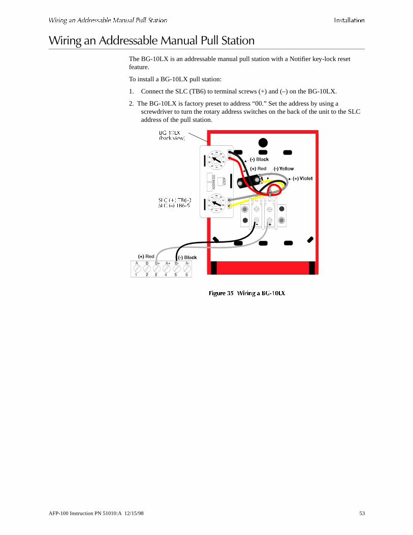
*��� �� ����������� ������ !��� ������ ������������
LC
<����#������������)���/��������������
The BG-10LX is an addressable manual pull station with a Notifier key-lock reset feature.
To install a BG-10LX pull station:
1. Connect the SLC (TB6) to terminal screws (+) and (–) on the BG-10LX.
2. The BG-10LX is factory preset to address “00.” Set the address by using a screwdriver to turn the rotary address switches on the back of the unit to the Saddress of the pull station.
������ �� 0����� �8"�#/5
%B,�!@*����� ?���
�@/ �<� 5%>,:�@/ �=� 5%>,2
AFP-100 Instruction PN 51010:A 12/15/98 53

������������ *��� ��������
ive
SLC he
<����#�+������
To install addressable detectors:
1. Connect the SLC to terminal (–) and (+) on the removable terminal block.
2. If using an RA400Z Remote LED Annunciator, connect the RA400Z positive terminal to the RA (+) terminal on the removable terminal block and the negatterminal to the RA (–) terminal on the removable block.
3. Before installing the appropriate addressable detector head, set the detector’s address on the head with a small flathead screwdriver. Mark this address on thead.
4. Place the removable terminal block into the connector in the detector head. Becertain to properly align and snap-in securely.
������ �� 0����� (������� &��3 ,���9� � ! ��"�� ���������
/$����� �<�
/$����� �=�
/$����� �<�
/$����� �=�
� �$� ��D� ��?���� �$� �@/�@/
%��� %2!�
��.!!8 ����� @&���� ������
����
����
�
������
54 AFP-100 Instruction PN 51010:A 12/15/98

*��� ������� ������� ������������
s)
ctor, e
<����#���������/�����
��������
The control panel supports the following optional modules:
• Fire•Lite RTM-8F Relay/transmitter Module• PIM-24 Printer/PC Interface Module• UDACT Universal Digital Alarm Communicator/Transmitter• DIM-485 Display Interface Module (for use with LCD-2x20 Series annunciator
-�������#��������1����*�/0���/����
To install an Fire•Lite RTM-8F module, follow these steps:
1. Cut jumper JP4 (to enable module placement supervision) on the main circuitboard.
2. Plug the Fire•Lite RTM-8F module into plug J6 on the main circuit board.
Note Devices connected to the standard EIA-485 connector, the optional EIA-232 connethe optional EIA-485 connector via the PIM-24 or DIM-485 modules or SLC may bprotected from voltage transients by using one of the UL-listed compatible surge suppressors listed in the Notifier Device Compatibility Document.
������ �$ )����� ���� � /�������
'�� ������� (6+,-. � �6+,.32
/ � '(. "�4���M@��� �5+,34� ���?����
'> (� ��4���M@��� �5+,34�� ��
'�> ������� K��/5
AFP-100 Instruction PN 51010:A 12/15/98 55

������������ *��� ������� �������
es or 0
to ntrol he CT
e d on d to fer to
f
o
5+����5���������+�#�������� ��� ������2����� ���
The UDACT transmits system status to UL-listed Central Station receivers via thepublic switched telephone network. It is capable of reporting up to 56 software zonup to 198 addressable points. The UDACT may be mounted directly to the AFP-10main circuit board or remotely in a UBS-1 or ABS-8R enclosure. For additional information, refer to the UDACT Manual.
WARNING Disconnect all sources of power (AC and DC) before installing or removing any modules or wiring.
1��� �������� %����� The UDACT may be mounted as follows:
• Directly to the main circuit board in the cabinent or
• Remotely in an ABS-8R or UBS-1 enclosure up to 6,000 feet (1,800 m) away fromthe control panel.
All power must be removed from the control panel before making any connectionsprevent circuit damage. The EIA-485 serial interface is connected between the copanel and UDACT, using twisted shielded pair wire. Power should be wired from tcontrol panel's 24 VDC (nominal) filtered, nonresettable output to TB1 on the UDA(except when mounted in the AFP-100).
�������� � 1��� ���� �� �*'$�22 �������Remove all power from the AFP-100 by disconnecting AC and batteries. Install thsupplied standoffs (three nylon and one aluminum) in the appropriate holes locatethe right side of the main circuit board. Carefully connect the ribbon cable provideconnector J16 on the main circuit board and to connector J10 on the UDACT. ReFigure 38 on page 57. Secure the UDACT to the aluminum standoff with screw provided.
The EIA-485 circuit and 24 VDC power are provided directly from connector J16 othe AFP-100. Note that a 120 ohm EOL resistor is not required on the UDACT EIA-485 terminals when it is installed inside the AFP-100 cabinet. The EOL resistor is required at the last device (if any are installed) on the EIA-485 line external to the control panel.
'�����((���Refer to “System Edit” on page 79, for information on programming the AFP-100 tfunction with the UDACT.
!
56 AFP-100 Instruction PN 51010:A 12/15/98
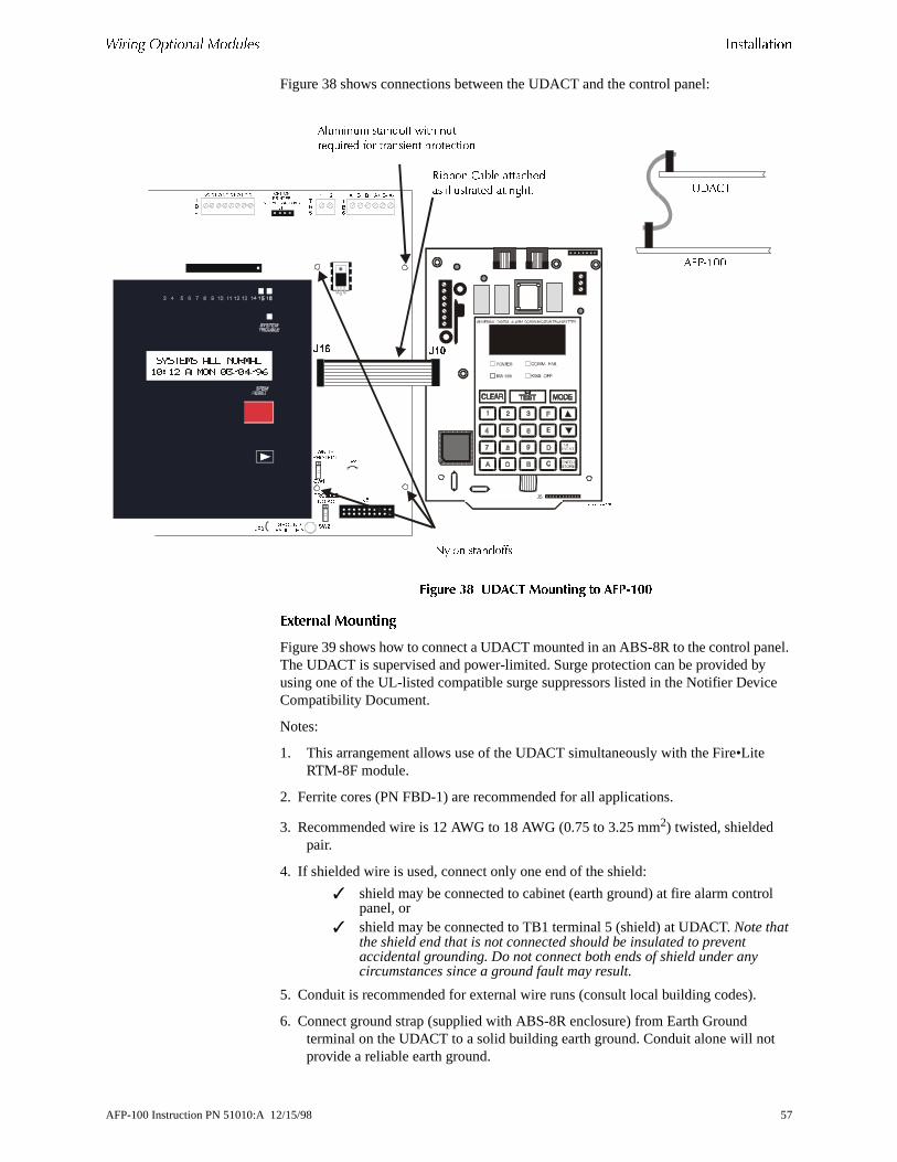
*��� ������� ������� ������������
nel. ce
l
Figure 38 shows connections between the UDACT and the control panel:
������ �% .( �� �������� �� �!"�##
3������ ��������
Figure 39 shows how to connect a UDACT mounted in an ABS-8R to the control paThe UDACT is supervised and power-limited. Surge protection can be provided byusing one of the UL-listed compatible surge suppressors listed in the Notifier DeviCompatibility Document.
Notes:
1. This arrangement allows use of the UDACT simultaneously with the Fire•Lite RTM-8F module.
2. Ferrite cores (PN FBD-1) are recommended for all applications.
3. Recommended wire is 12 AWG to 18 AWG (0.75 to 3.25 mm2) twisted, shielded pair.
4. If shielded wire is used, connect only one end of the shield:
✓ shield may be connected to cabinet (earth ground) at fire alarm contropanel, or
✓ shield may be connected to TB1 terminal 5 (shield) at UDACT. Note that the shield end that is not connected should be insulated to prevent accidental grounding. Do not connect both ends of shield under any circumstances since a ground fault may result.
5. Conduit is recommended for external wire runs (consult local building codes).
6. Connect ground strap (supplied with ABS-8R enclosure) from Earth Ground terminal on the UDACT to a solid building earth ground. Conduit alone will notprovide a reliable earth ground.
������� ��� ����
� ��� � � �� ����
�� ��� �� � �� �� � � �
���
��� ���
�����
����
� ������ ����
�����
�����
�� ��
�� �� ���
�� ���
� ��
��
��
��
���
���
� � �� �� �� ��
�
�
�
�
�
�
�
�
�
J5���������
�� ��� � �����"" ��$ � ���C ���� "� ��������� ��������
����� /���� �����$���� ��� ������� �� �� $�;
0��� �����""�
�4(,�!!
K��/5
AFP-100 Instruction PN 51010:A 12/15/98 57
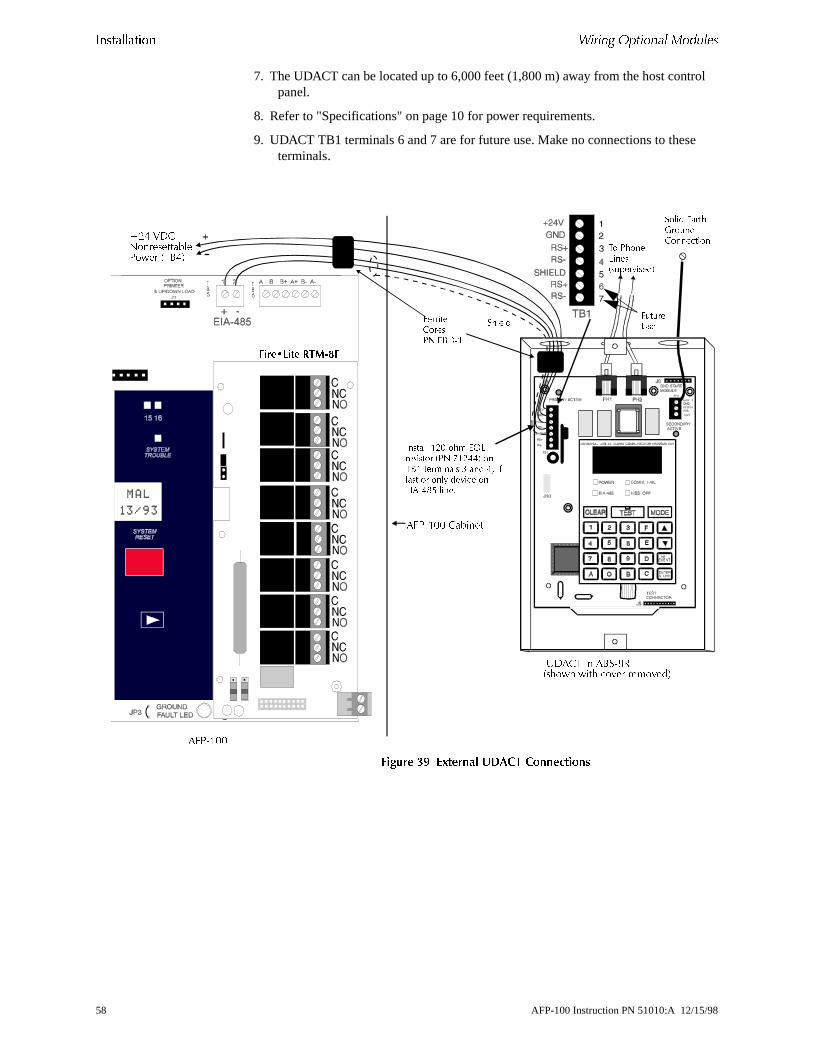
������������ *��� ������� �������
rol
e
7. The UDACT can be located up to 6,000 feet (1,800 m) away from the host contpanel.
8. Refer to "Specifications" on page 10 for power requirements.
9. UDACT TB1 terminals 6 and 7 are for future use. Make no connections to thesterminals.
������ �' :;���� .( �� �����������
<-. 9�/0�����������(�� �5%.�
;������+����!� ;#&�2
�� !���"���,� ��������-
)���� 8����<�� �+������
; � ��5��)�����
�4(,�!! /������
������ 23= ��� 87"�������� ,!� /23��- ��#2 �������� : �� �� ������ �� ��� ������ �8�%��>4 ����
K��/5 �� �%�,3���$� ��$ �?�� ���?���
�4(,�!!
��01�� ��.�2�
58 AFP-100 Instruction PN 51010:A 12/15/98

*��� ������� ������� ������������
. r for
is bus ded
ons.
ect be
��/0�*�*������������/����
WARNING Disconnect all sources of power (AC and DC) before installing or removing any modules or wiring.
The ACM-8R module provides eight Form-C relays with contacts rated for 5 ampsWhen installed with an AFP-100, the ACM-8R modules provide relay activation foeach of the 56 possible FACP zones plus special functions. Options exist to allowalarm only or alarm and trouble activations per zone. Output activation for generalalarm, general trouble, general supervisory, NAC fault, AC fail, walktest start and battery trouble are also available. Refer to the ACM-8R Manual Appendix for information on setting module switches for addressing and relay functions.
������ �# �"%, :�� �����
The ACM-8R is installed on the standard EIA-485 communication bus and wiring supervised by the FACP. Power for the module must be power-limited and may beprovided by the FACP or a UL-listed power supply such as the FCPS-24. Up to 32ACM-8R Relay Control Modules may be placed onto the EIA-485 communication (if no other devices are installed on the bus). Removable terminal blocks are provifor ease of wiring installation and servicing. Refer to the ACM-8R Manual for UL power-limited wiring requirements and switch SW4 receive/transmit selection optiThe ACM-8R module can be mounted remotely in an ABS-8R annunciator surface-mount backbox.
CAUTION It is vitally important that, following relay programming, all relays be tested for corractivation by triggering zones and/or special functions at the FACP. It should also noted:
• ACM-8R relays will activate during the Alarm Presignal sequence• ACM-8R relays will not activate during the Alarm Verification Retard and Reset
Periods
!
!
AFP-100 Instruction PN 51010:A 12/15/98 59

������������ *��� ������� �������
Figure 41 shows how to mount an ACM-8R
������ �� 0����� �3� ��"%,
#".�2�
�4(,�!!
&6�,.32 5%2,� �<� ��� - �=�0����������� -. 9�/ (��) � 5%.,: �<� ��� . �=�
60 AFP-100 Instruction PN 51010:A 12/15/98

*��� ������� ������� ������������
ge of ht the n ion
is is
����1����*�/0���������/�����-���������
WARNING Disconnect all sources of power (AC and DC) before installing or removing any modules or wiring.
Insert the three supplied nylon standoffs into the holes located on the right-side edthe AFP-100 main circuit board. Insert the supplied metal standoff on the lower-rigcorner. Carefully align the pins of J6 on the main circuit board with connector J1 onFire•Lite RTM-8F option board. Press firmly on the Fire•Lite RTM-8F until it locks iplace on the standoffs. Affix the terminal identification labels provided with the optmodule.
Note Be certain to tighten the screw into the metal standoff on the lower-right corner. Thcritical to the Fire•Lite RTM-8F transient protection.
������ �- ����2/��� ,��"%� ���� � 4��� ����
!
��01�� ��.�2�
#��� -- .��� "����� ����N ���$ �� ��� � �����"" ��$ � ���C ���� "� ��������� ��������
N ���$ ���� �����""�
K�� ����� ���� ��� �����"" $���
+��� /��� �� %���
������ $���
��01�� ��.�2� & ����.����
�����""�
AFP-100 Instruction PN 51010:A 12/15/98 61

������������ *��� ������� �������
0 s
arity )
tion.
.
Figure 43 shows the components on the Fire•Lite RTM-8F board:
������ �� ����2/��� ,��"%� ,� � ���������� ���� � ����������
Notes:1. Zone Relay Contact Ratings:
✓ Maximum Switched Power is 170W or 1800 VA✓ Maximum Switched Current is 6 amps✓ Maximum Switched Voltage is 30 VDC or 300 VAC✓ UL Rating is 6 amps @ 28 VDC or 120/300 VAC 1/8 HP @ 120/24
VAC (100,000 CYC) 1.5/0.8 A @ 120/240 VAC Pilot Duty i30,000 CYC
✓ Contact Material is Silver Nickel, Gold Plated
2. Polarity Reversal Output: 24 VDC (nominal), 18.5 mA maximum rated current. Internal Resistance: 1,200 ohms (nominal). Intended for connection to the polreversal circuit of a remote station receiving circuit (such as the Notifier RS-82having compatible ratings. The Fire•Lite RTM-8F is not suitable for separate transmission of both alarm and trouble signals simultaneously to a remote staOutput is power-limited and wiring can leave the building.
Continued on the next page..
�����
���
��
0��� 6" ������ ��� ��� �����,������� ���� ���#����� � ������ ����� ��������� ���� �� ���������;
8�� �
8�� -
8�� :
8�� .
8�� 2
8�� >
8�� 1
8�� 3
����� &������� "8& ,������-���������� &������� "8& ,������-
���������� 7 �� �,?- �����,$- �����
9���� )������
@2 ,� ��� �� ���� �� �����-
����� ��������� ����$
5���������� ��������� ����$
����$ ������ �
�����������
0����
3�� , ' ���� ������ ��
������5� ��� (��������?����� ����� �������(��,��������
����� )��� (������ ��?���������� �������(��,��������
@��� &��� � + ������� %D�0����,��������
@��� &��� � + �������%D 5� ��� @&� ������
'(� , / � "� (������ ��?���������� ������ �������
62 AFP-100 Instruction PN 51010:A 12/15/98

nd
ing
t is ox tput must must r the
ise
3. Municipal box output: Supervised for open circuit. Output is nonpower-limited awiring can leave the building. Yellow Trouble LED, when on, indicates open circuit condition. Check wiring and make certain Municipal Box is reset accordto local codes. Maximum current (short circuit) is 0.6 amps. Maximum Voltage(open circuit) is 30.0 V. Maximum Wire Resistance is 3 ohms.
4. To prevent the yellow Trouble LED from turning on when the Transmitter Outpunot used (no connections), move jumper JP2 to the Local Energy Municipal Bposition (bottom two pins) and install a dummy load across the Transmitter Outerminals as shown below. The dummy load is a 1N4004 diode. The cathode be connected to the terminal labeled '(–) normal' in Figure 43, and the anode be connected to the terminal labeled '(+) normal'. Polarity must be observed oTrouble LED will remain on.
Caution The diode must be removed when using the Transmitter Output to properly supervthe connections.
!
�0.!!.5����������) �� �
AFP-100 Instruction PN 51010:A 12/15/98 63
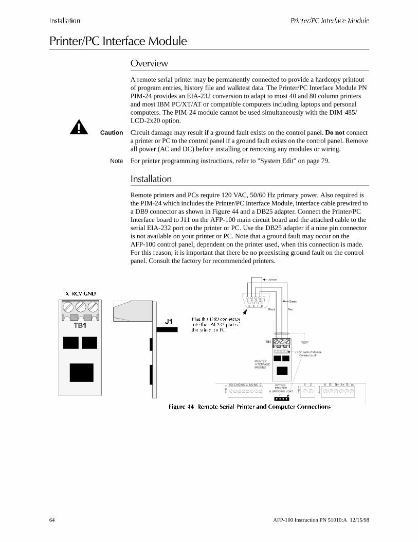
������������ !�����/!� ��������� ������
tout PN rs /
ove
is d to PC o the ctor
ade. trol
������2���-��������/����
��������
A remote serial printer may be permanently connected to provide a hardcopy prinof program entries, history file and walktest data. The Printer/PC Interface ModulePIM-24 provides an EIA-232 conversion to adapt to most 40 and 80 column printeand most IBM PC/XT/AT or compatible computers including laptops and personalcomputers. The PIM-24 module cannot be used simultaneously with the DIM-485LCD-2x20 option.
Caution Circuit damage may result if a ground fault exists on the control panel. Do not connect a printer or PC to the control panel if a ground fault exists on the control panel. Remall power (AC and DC) before installing or removing any modules or wiring.
Note For printer programming instructions, refer to "System Edit" on page 79.
-���������
Remote printers and PCs require 120 VAC, 50/60 Hz primary power. Also requiredthe PIM-24 which includes the Printer/PC Interface Module, interface cable prewirea DB9 connector as shown in Figure 44 and a DB25 adapter. Connect the Printer/Interface board to J11 on the AFP-100 main circuit board and the attached cable tserial EIA-232 port on the printer or PC. Use the DB25 adapter if a nine pin conneis not available on your printer or PC. Note that a ground fault may occur on the AFP-100 control panel, dependent on the printer used, when this connection is mFor this reason, it is important that there be no preexisting ground fault on the conpanel. Consult the factory for recommended printers.
������ �� ,����� ��� !������ �� �������� �����������
!
!� ���� &#A ���������� ��� 8%��3:3 ���� ����� ������ �� !+�
�/ �"4 5�,
64 AFP-100 Instruction PN 51010:A 12/15/98
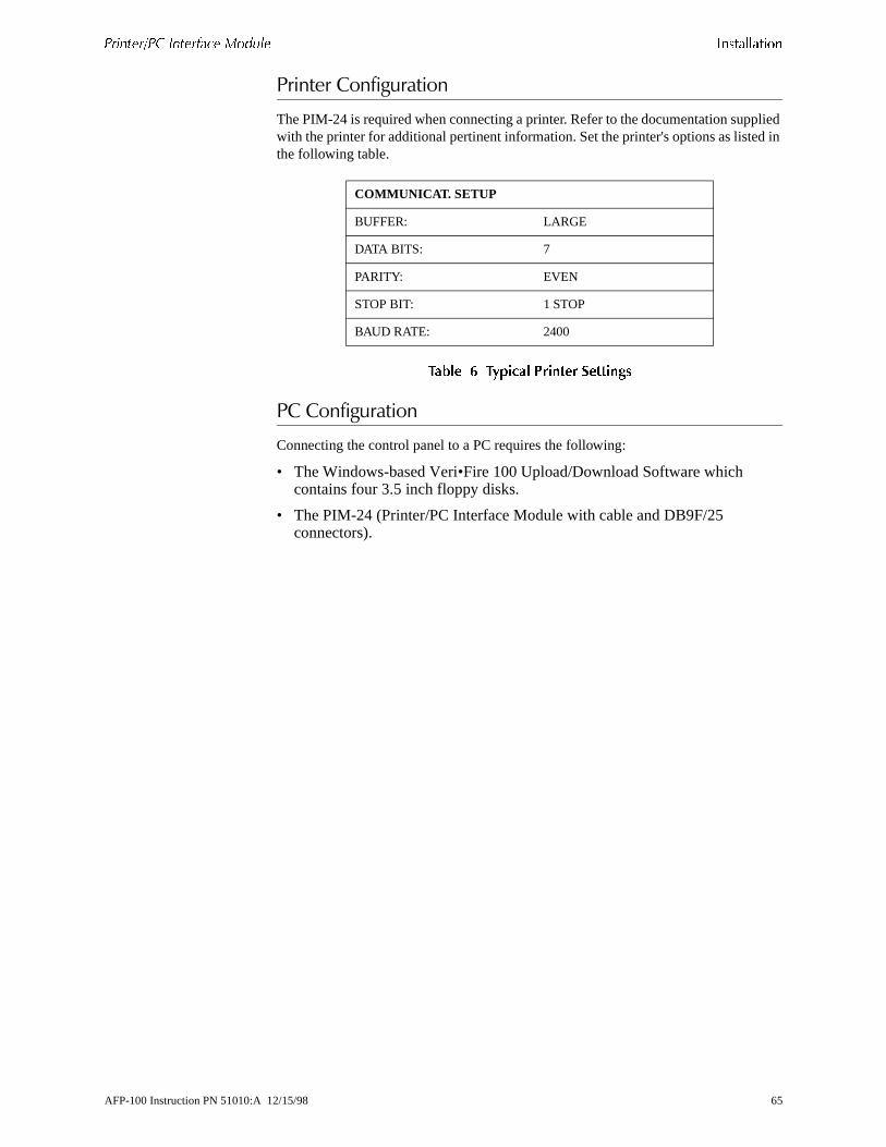
!�����/!� ��������� ������ ������������
plied d in
������������#�����
The PIM-24 is required when connecting a printer. Refer to the documentation supwith the printer for additional pertinent information. Set the printer's options as listethe following table.
����� 4 �"���� '������ �������
��������#�����
Connecting the control panel to a PC requires the following:
• The Windows-based Veri•Fire 100 Upload/Download Software which contains four 3.5 inch floppy disks.
• The PIM-24 (Printer/PC Interface Module with cable and DB9F/25 connectors).
COMMUNICAT. SETUP
BUFFER: LARGE
DATA BITS: 7
PARITY: EVEN
STOP BIT: 1 STOP
BAUD RATE: 2400
AFP-100 Instruction PN 51010:A 12/15/98 65

������������ !�����/!� ��������� ������
�����
66 AFP-100 Instruction PN 51010:A 12/15/98

your
re
the
fic large
ories,
t, the
d rite ain ter
er a gram
SECTION 3 PROGRAMMING AND READ STATUS
��������
This section provides detailed instructions for programming the control panel. For convenience, a Programming Flowchart has been included in "Screen Options Flowchart" on page 131. It may be helpful to follow along with the flowchart as thissection is reviewed.
The control panel is completely field programmable and requires no special softwaskills. Programming may be accomplished in one of three ways:
• The Autoprogram Feature - this method is very convenient for quickly bringingcontrol panel on-line or for program editing
• Manual Programming or editing, using the control panel keypad• The Off-Line Programming Feature - this method allows creation of site-speci
custom programs using a Windows-based computer. For programs requiring aamount of data entry, this method may be preferred. You can order the Veri•Fire 100 Off-Line Programming Utility kit for off line programming.
When a programmed system is normal with no active alarms, troubles or supervisthe 'SYSTEMS ALL NORMAL' screen will be displayed as shown below:
To (1) program the system, (2) read system status, (3) print, (4) edit or (5) WalktesENTER key must first be pressed. After pressing the ENTER key, the following screen displays:
Pressing the 1 key will select system Programming, which may only be accomplisheby an authorized user. Before attempting to program the system, place the SW1 WProtect switch in the down position. SW1 is located on the lower-right side of the mcircuit board. If the switch is in the up 'Write Protect' position while attempting to enthe Programming Mode, the following message appears in the LCD display:
To program the system (Program Level 1 and Program Level 2), you must first entvalid password. Once the correct password is entered, the you can select Autopro
����������������
� � ����� �� ����
���������������
��������������������
���������������
���������������
AFP-100 Instruction PN 51010:A 12/15/98 67

����������� ��� ��� ������ �0��0�"
able, l 2,
oint/ram. "Read
C n is
tem. ng
or Program Edit. After programming is completed, return switch SW1 to the Write Protect position.
1 = Programming: There are two programming levels.
• Program Level 1 is for system configuration in which data relating to device types, zoning, messages, etc. is entered into the system memory.
• Program Level 2 is where a qualified operator can access features such as DisClear History, Walktest, Time Change and Program Check. For Program Levethe SW1 Write Protect switch should remain in the up 'Write Protect' position.
2 = Read Status: Entering Read Status allows the user to read the status of any pzone in the system plus display or print the history file or print the entire user progThe Read Status feature is NOT password protected. Read Status is explained in Status" on page 101.
3 = AC/BAT: Entering AC/BAT allows the user to read the battery voltage and the Aline voltage. The AC/BAT feature is NOT password protected. The following screedisplayed upon entering AC/BAT:
"Initial Power-up" on page 69 describes initial programming procedures for a new system. The same procedures are used to modify programming in an existing sysMake certain the SW1 Write Protect switch is in the down position before attemptiany Level 1 Programming functions.
����������� � �!
���������� � !
68 AFP-100 Instruction PN 51010:A 12/15/98

����� !�"��)�� ����������� ��� ��� ������
larm nel, ill
utes.
-�����������0�
After completing the wiring of addressable devices to the SLC, power up the fire asystem. Because the addressable devices are not programmed into the control patheir LEDs will not flash, the System Trouble LED will be on and the LCD display walternate between the following two displays:
If the system remains unprogrammed, the panel sounder will activate after two minIt can be silenced by pressing the ACKNOWLEDGE/STEP switch, but it will continue to resound until the system is programmed.
���������������
���������������
���������������
���!�����������
AFP-100 Instruction PN 51010:A 12/15/98 69
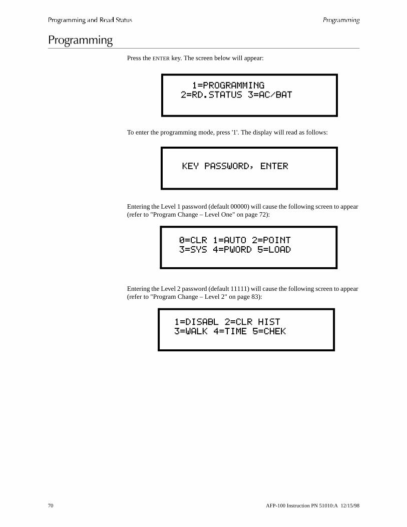
����������� ��� ��� ������ !�������
pear
pear
���#�� ��#
Press the ENTER key. The screen below will appear:
To enter the programming mode, press '1'. The display will read as follows:
Entering the Level 1 password (default 00000) will cause the following screen to ap(refer to "Program Change – Level One" on page 72):
Entering the Level 2 password (default 11111) will cause the following screen to ap(refer to "Program Change – Level 2" on page 83):
�������������
��������������������
�����������"�����
����������������
������ ������#����
���������������$���
������� ������#��$��
70 AFP-100 Instruction PN 51010:A 12/15/98

!���"���� ����������� ��� ��� ������
l the can invalid
edly.
tings.
���������
There are two factory set programming passwords, '00000' and '11111', which wilaccess two different screens as indicated in the preceding section. From either of screens, access to specific system and device programming may be obtained. Allprogramming entries are stored in nonvolatile memory. The factory set passwordsbe changed by the user and a method exists to clear one or both passwords. If an password is entered, the display will read 'INCORRECT PASSWORD'. To exit fromProgramming operations at any time, press the Backspace (left arrow) key repeat
Note For Canadian applications, both passwords must be changed from the factory set
AFP-100 Instruction PN 51010:A 12/15/98 71

����������� ��� ��� ������ !����� �,���� 1 ��0�� ���
shes lay
from , the
the to sible.
g with
If
oun dress.
Be
e
���#�� ��:��#�������������
When the correct password is entered, the control panel will enter Level 1 programmode. In this mode, the trouble relay is activated and the System Trouble LED flaand cannot be changed to steady and the panel sounder is off. The following dispwill appear:
�����
The Clear function is useful when the control panel is first installed, before autoprogramming. Pressing the 0 key clears all general system programming optionsdescribed in "System Edit" on page 79, and all programmed addressable devices the nonvolatile memory of the control panel. Before executing the Clear commanddisplay will prompt the user to press the ENTER key to verify the command before the system actually clears programming data.
Note It is necessary to autoprogram the control panel after using the clear function.
�����#��
The first time the system is brought on-line, it must be autoprogrammed. Pressing1 key enters the Autoprogramming mode. The main purpose of autoprogramming isallow the installer a fast and easy way to bring the system on-line as quickly as pos
Note Autoprogram is also the only way to add or delete devices.
Once Autoprogram is selected, the control panel automatically polls all devices installed/wired to the SLC. The control panel communicates with each individual addressable device and displays the type of device at each address location startindetectors and then modules.
While autoprogramming the system, the control panel will display the following:
Verification of each device address and type installed on the SLC may now occur.information is correct, press the ENTER key to save the device in the program; if incorrect, press the left arrow key to delete the device. In addition, adjective and ndescriptors plus zone assignments may be added to the display field per device adIf the SYSTEM RESET key is pressed at this time or the control panel is allowed to time-out after 10 minutes of inactivity, a “System Corrupted” message will appear.certain to step through all devices, using the ENTER or left arrow key.
The first time that autoprogramming is selected, all points installed on the SLC are identified. Default device type (monitor, smoke detector, control) and software zonassignments for each device are displayed. On any successive enabling of the
����������������
������ ������#����
���������
�����������
72 AFP-100 Instruction PN 51010:A 12/15/98

!����� �,���� 1 ��0�� ��� ����������� ��� ��� ������
r
t dress ss are
nd
und
.es C
“H” n be
e, dure.
rsor e
e
r the is
ield hen
ored w or
autoprogram feature, the LCD display only displays the newly installed, deleted, ochanged devices on the SLC.
Devices which match the program already in memory are not changed and are noshown to the operator. Devices which do not match the program (not the same adand/or type) are shown to the operator. Devices inadvertently set to the same addreidentified and displayed on the screen.
)�, ������
For each new detector, the Autoprogram feature selects default program values apresents the information to the user. A typical example follows:
In the preceding example:
• “P” in “P01” represents the actual Type Code (photoelectric) of the detector foat address 01. ('I' would represent an Ionization detector).
• The ADJ (adjective) and NOUN fields are blank, but may be user programmed• “MZ00” is the default detector sensitivity and zone selection where “M” indicat
medium sensitivity and “Z00” indicates “general alarm” (main circuit board NAoutputs 1 and 2). Refer to "Software Zones" on page 107, for software zone assignments. Sensitivity setting sincludes (H)igh, (M)edium, and (L)ow where indicates the highest sensitivity to smoke. The zone and detector sensitivity causer-programmed.
After the new detector is displayed, press the ENTER key to accept the default information shown or press the left arrow (triangle to the left of the ENTER key) to reject the autoprogram information and not enter it into memory. In most cases, adjectivnoun descriptors and zone assignments will be added by using the following proce
The control panel will lead you through the program editing process. A blinking cumoves through the fields as you press the right arrow key (triangle to the right of thENTER key). After moving into other fields, you may return to a previous field by pressing the left arrow. Change the blinking fields by pressing the up arrow key, thdown arrow key or by pressing the appropriate numeric key.
Custom words may be entered via the keypad. The alphanumeric operation of thekeypad changes a blinking letter in the ADJ and NOUN fields. For example, to enteletter “R,” repeatedly press the 7 key to step through 7, P, R and S, stopping when Rdisplayed. Press the right arrow key (do not press the ENTER key at this time) to move to the next letter display position.
The ADJ field serves one of two puposes:
• Allow a second zone to be associated with the detector. For example, entering “Z10” associates the detector with zone 10. Because the ADJ fcan be five characters long, the last two characters should not be used wassociating a second zone.
• Provide an adjective portion of the description for the detector.
To reduce the number of key presses, the user may also select from a library of stwords. The ADJ field library provides five-character words selected by the up arro
����������������� �
%��&'���%�'����(
AFP-100 Instruction PN 51010:A 12/15/98 73

����������� ��� ��� ������ !����� �,���� 1 ��0�� ���
ied rary. t his
or. oves the tter
ursor
the
er. last
nd the
down arrow keys from the following list of available words:
����� 5 ��6����� ������"
The ADJ (adjective) field may be loaded from the library list above and then modifletter-by-letter if desired. Pressing the up or down arrow keys steps through the libOnce the up or down arrow keys are pressed, the blinking cursor moves to the lascharacter of the ADJ field, assuming that the user will next want to move beyond tfield.
Pressing a key on the 12-key pad changes the letter indicated by the blinking cursAny alphanumeric character may be entered. Pressing the right or left arrow key mthe blinking cursor one letter right or left. When the right arrow key is pressed withblinking cursor on the last letter of the ADJ label, the cursor will move to the first leof the NOUN field.
Altering the NOUN field is done in a similar way. Use the up or down arrow keys tostep through the NOUN library which is listed below:
����� 7 )��� ������"
In addition, the user may use the Recall/Increment function at any time when the cis on the first letter of the ADJ or NOUN field as follows:
• If the 0 key is pressed, a '0' is placed in the first letter position.• If the zero key is then pressed a second time with no intervening key actions,
entire ADJ field is replaced with the field entered for the previous device programmed, and the cursor moves to the last character of the field (Recall function). The Recalled ADJ or NOUN field may now be changed letter-by-lett
• If the 0 key is pressed again with no other intervening key actions and the lastcharacter in the field is a number '0-9', the number is incremented by one. If thecharacter is a letter, it changes to a '0'. If the last character goes from 9 to 0 acharacters to the left of the last character are also numbers, they are also incremented (overflow).
_____ (default of blanks)NORTHSOUTH_EAST_WESTFRONTCENTR_REARUPPERLOWER_MAIN
FIRST__2ND__3RD__4TH__5THFLR_1FLR_2FLR_3FLR_4FLR_5RM___
_________ (default of blanks)BASEMENT_BOILER_RMCLASSROOMCLOSET___CORRIDOR_ELECT._RMELEVATOR_ENTRANCE_FLOOR____GARAGE___HALLWAY__
HVAC_ROOMKITCHEN__LOBBY____OFFICE___PATIENT__RESTROOM_ROOM_____STAIRWAY_STOREROOMWING_____ZONE_____
74 AFP-100 Instruction PN 51010:A 12/15/98
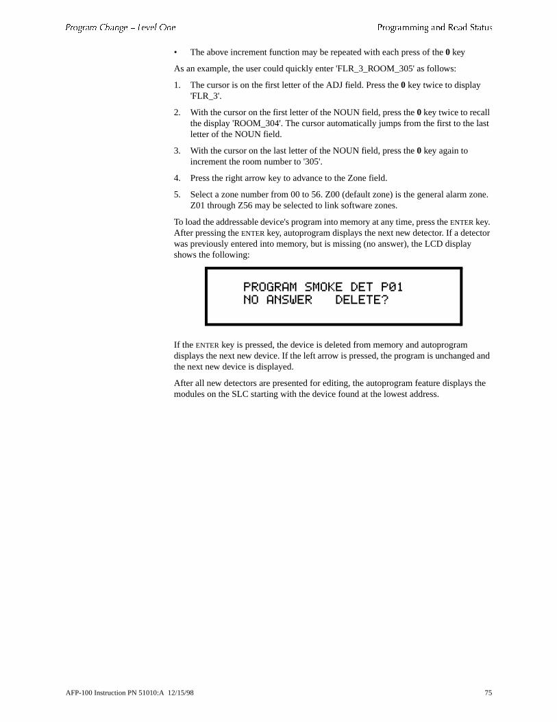
!����� �,���� 1 ��0�� ��� ����������� ��� ��� ������
ast
one.
tor
d and
the
• The above increment function may be repeated with each press of the 0 key
As an example, the user could quickly enter 'FLR_3_ROOM_305' as follows:
1. The cursor is on the first letter of the ADJ field. Press the 0 key twice to display 'FLR_3'.
2. With the cursor on the first letter of the NOUN field, press the 0 key twice to recall the display 'ROOM_304'. The cursor automatically jumps from the first to the lletter of the NOUN field.
3. With the cursor on the last letter of the NOUN field, press the 0 key again to increment the room number to '305'.
4. Press the right arrow key to advance to the Zone field.
5. Select a zone number from 00 to 56. Z00 (default zone) is the general alarm zZ01 through Z56 may be selected to link software zones.
To load the addressable device's program into memory at any time, press the ENTER key. After pressing the ENTER key, autoprogram displays the next new detector. If a detecwas previously entered into memory, but is missing (no answer), the LCD display shows the following:
If the ENTER key is pressed, the device is deleted from memory and autoprogram displays the next new device. If the left arrow is pressed, the program is unchangethe next new device is displayed.
After all new detectors are presented for editing, the autoprogram feature displaysmodules on the SLC starting with the device found at the lowest address.
����������������� �
���������������)
AFP-100 Instruction PN 51010:A 12/15/98 75
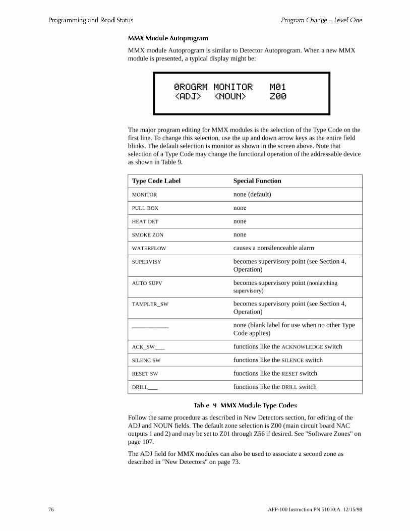
����������� ��� ��� ������ !����� �,���� 1 ��0�� ���
the ield
ice
he
s" on
��� ������ ����������(
MMX module Autoprogram is similar to Detector Autoprogram. When a new MMXmodule is presented, a typical display might be:
The major program editing for MMX modules is the selection of the Type Code onfirst line. To change this selection, use the up and down arrow keys as the entire fblinks. The default selection is monitor as shown in the screen above. Note that selection of a Type Code may change the functional operation of the addressable devas shown in Table 9.
����� 8 ��� ������ �"�� ����
Follow the same procedure as described in New Detectors section, for editing of tADJ and NOUN fields. The default zone selection is Z00 (main circuit board NAC outputs 1 and 2) and may be set to Z01 through Z56 if desired. See "Software Zonepage 107.
The ADJ field for MMX modules can also be used to associate a second zone as described in "New Detectors" on page 73.
Type Code Label Special Function
MONITOR none (default)
PULL BOX none
HEAT DET none
SMOKE ZON none
WATERFLOW causes a nonsilenceable alarm
SUPERVISY becomes supervisory point (see Section 4, Operation)
AUTO SUPV becomes supervisory point (nonlatching supervisory)
TAMPLER_SW becomes supervisory point (see Section 4, Operation)
___________ none (blank label for use when no other TypeCode applies)
ACK_SW___ functions like the ACKNOWLEDGE switch
SILENC SW functions like the SILENCE switch
RESET SW functions like the RESET switch
DRILL___ functions like the DRILL switch
������������� �
%��&'��%�'����(
76 AFP-100 Instruction PN 51010:A 12/15/98
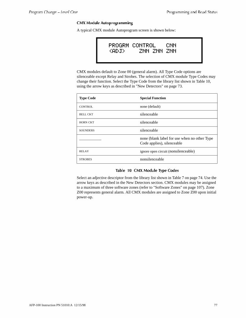
!����� �,���� 1 ��0�� ��� ����������� ��� ��� ������
may ,
e the igned one nitial
��� ������ ����������((���
A typical CMX module Autoprogram screen is shown below:
CMX modules default to Zone 00 (general alarm). All Type Code options are silenceable except Relay and Strobes. The selection of CMX module Type Codeschange their function. Select the Type Code from the library list shown in Table 10using the arrow keys as described in "New Detectors" on page 73.
����� �2 ��� ������ �"�� ����
Select an adjective descriptor from the library list shown in Table 7 on page 74. Usarrow keys as described in the New Detectors section. CMX modules may be assto a maximum of three software zones (refer to "Software Zones" on page 107). ZZ00 represents general alarm. All CMX modules are assigned to Zone Z00 upon ipower-up.
Type Code Special Function
CONTROL none (default)
BELL CKT silenceable
HORN CKT silenceable
SOUNDERS silenceable
___________ none (blank label for use when no other TypeCode applies), silenceable
RELAY ignore open circuit (nonsilenceable)
STROBES nonsilenceable
��������������
%��&'����(�(�(
AFP-100 Instruction PN 51010:A 12/15/98 77

����������� ��� ��� ������ !����� �,���� 1 ��0�� ���
l
ss, is
or), r
her
ng e *
KT'
is
�����.��
While displaying the Program Level 1 Menu screen (see "Program Change – LeveOne" on page 72), pressing the 2 key allows for editing of the point (addressable device) descriptor screens. These screens show the device type, the device addreadjective and noun field descriptors and the software zone locations that the pointassigned to. Point editing is performed after autoprogramming and may be done at anytime, except during an alarm condition. The following display will appear:
For example, select Detector address 3 program edit by pressing * key (* = detectfollowed by numeric key '3', followed by the ENTER key. To select module address 3 foprogram edit, press the # key (# = module), press the 3 key, then press the ENTER key. If there is no device installed at this address, the control panel displays the next higaddress where a device is installed. After finished editing, press the ENTER key, the display returns to the above menu. Rather than reentering the next point number, the user may press the up or down arrow key to display the next lower or higher existipoint. Using software PN #AFP100V1.0 or greater, to edit NAC 1 or NAC 2, press thkey, then the # key, the press '1' for NAC 1 or '2' for NAC 2. Select either 'BELL_Cfor silenceable functionality or 'STROBE' for nonsilenceable functionality. Use the system edit menu described in "System Edit" on page 79, to select coding. Codingonly possible if the NAC is programmed as 'BELL_CKT'. The point display formatsand the method of editing are described in "Autoprogram" on page 72.
���������������
������*�+"���"����
78 AFP-100 Instruction PN 51010:A 12/15/98

!����� �,���� 1 ��0�� ��� ����������� ��� ��� ������
.
the
���� �.��
The System Edit function is selected by pressing the 3 key. The system edit screen appears as shown below. This software does not support the LCD-2x20 Annunciator
Use the up and down arrow keys to scroll through the choices for each option andleft and right arrow keys to move from option to option.
!,�������������
���������� �����
AFP-100 Instruction PN 51010:A 12/15/98 79

����������� ��� ��� ������ !����� �,���� 1 ��0�� ���
n
r
The
8
There are eight system function options for software releases prior to PN #AFP100V1.0. The factory default selections and user option selections are showbelow:
����� �� �" ��( *������ %�����
The system edit screen appears as shown below for software PN #AFP100V1.0 ogreater. This software is required to support the LCD-2x20 Series Annunciators.
There are nine system function options for software PN #AFP100V1.0 or greater. factory default selections and user option selections are shown below:
Function Default Selection
VF = Alarm Verification
(N)one (Y) 120 seconds
SI = Silence Inhibit (N)one (Y) 60 seconds1
AS = Autosilence (N)one (Y) 10 minutes1
PS = Presignal (N)one (Y) 3 minutes with 15 second
Acknowledge1
CD = Bell Code 1Note: Bell 2 is fixed steady
(M)arch Time (N)one(T) = Temporal(C) = California
AN = Annunciators (N)one (Z) = 56 Zones(ZU) = 56 Zones Annunciator with
UDACT2
(P) = 198 Points(PU) = 198 Points Annunciator with
UDACT2
ST = SLC style (4) = Style 4 (6) = Style 6
REM = Alarm/Trbl Reminder
(N)o (Y)es = Sound onboard piezo every 15 seconds during alarm and every two minutesduring trouble after pressing the ACKNOWLEDGE or SILENCE key.
1 Requires prior approval of Local Authority Having Jurisdiction.
2 When the UDACT has a fault, this entry allows the FACP to display 'DACT Trouble' on the LCD display and printer hardcopy. The history file will also be updated with this information. For zone annunciation, up to 56 zones, use AFM Series Annunciators or LDM Series Annunciators. For 19point annunciation, use the LDM Series Annunciators.
Function Default Selection
V = Alarm Verification (N)one (Y) 120 seconds
I = Silence Inhibit (N)one (Y) 60 seconds1
A = Autosilence (N)one (Y) 10 minutes1
!�������������
������������� ���
80 AFP-100 Instruction PN 51010:A 12/15/98

!����� �,���� 1 ��0�� ��� ����������� ��� ��� ������
.
us
the . nd
reen.
8
����������:��#�
While displaying the Program Menu, press the 4 key to change either of two passwordsOne high level password, defaulted to '00000', allows for point and system programming. A second lower level password, defaulted to '11111', allows for statchanges such as:
• Disable points/zones• Clear history file• Walktest enable• Time and date set• Program check
Pressing the 4 key will display the following:
Select the password to change by typing * or #, then enter the new password. As new program or status password is entered, it is displayed. When the enter key ispressed, the display reads PRESS ENTER IF OK, NNNNN=NEW PROGRAM PWAfter the ENTER key is pressed, the new password is stored in EEPROM memory athe program returns to the program change screen. If BACKSPACE is entered, thepassword remains unchanged and the program returns to the program change sc
P = Presignal (N)one (Y) 3 minutes with 15 second Acknowledge1
C = Bell Code (N)one (M) = March Time(T) = Temporal(C) = California
A/U = Annunciators with or without UDACT
(N)one (Z) = 56 Zones
(ZU) = 56 Zones Annunciator with UDACT2
(P) = 198 Points(PU) = 198 Points Annunciator with
UDACT2
L/P = LCD-2x20 or Printer/PC in use
(N)one L = LCD-2x20 Series installed (requires DIM-485)P = Printer or local PC installed (requires PIM-24)
S = SLC style (4) = Style 4 (6) = Style 6
R = Alarm/Trbl Reminder
(N)o (Y)es = Sound onboard piezo every 15 seconds during alarm and every 2 minutesduring has been pressed
1 Requires prior approval of Local Authority Having Jurisdiction.
2 When the UDACT has a fault, this entry allows the FACP to display 'DACT Trouble' on the LCD display and printer hardcopy. The history file will also be updated with this information. For zone annunciation, up to 56 zones, use AFM Series Annunciators or LDM Series Annunciators. For 19point annunciation, use the LDM Series Annunciators.
Function Default Selection
*""�����!�������
+""�����!�������
AFP-100 Instruction PN 51010:A 12/15/98 81

����������� ��� ��� ������ !����� �,���� 1 ��0�� ���
l for e vice l. en
����
WARNING Changes to program entries occur as a result of the downloading process. After successful downloading, make sure to perform the following steps:
1 Print out all programmed data via the print mode or manually view programmed enteries and compare to intended program data.
2 Test all affected control panel operations.
3 Immediately corrent any problems that you find.
While displaying the Program Menu, program selection '5' sets up the control panetransfer of its application database from/to a Window-based computer. This may bused to save the program that exists in an control panel for security and future serreasons; or may be used to transfer a program created off-line to the control paneRefer to the AFP-100 Off-Line Programming Manual for additional information. Whthe Load option is selected, the following screen will be displayed:
The left arrow key may be used to return to the program change screen. The PC connects to the EIA-232 printer interface (instructions provided with the Upload/Download software kit). Continue to press the left arrow key to return to the main program screen.
!
��������������
����������,�����
82 AFP-100 Instruction PN 51010:A 12/15/98

the
ry,
���#�� ��:��#����������'
While the control panel is normal with no active alarms, troubles or supervisories, screen shown below will be displayed:
To access the programming mode, the ENTER key must be pressed, causing the following screen to be displayed:
Pressing '1' will cause the following screen to appear:
Enter the Level 2 password (default = 11111) then press the ENTER key to access Programming Change Level 2. The screen shown below will appear:
From this screen, the available function choices include point Disable, Clear HistoWalktest, Set Time and Check programming.
+���)��
Press the 1 key to display the following screen:
Press the * key to display detectors, the # key to display modules, enter the device
����������������
� � ���� �� ����
�������������
��������������������
�����������"�����
���������������$���
������� ������#��$��
�������������
������*�+"��"����
!
AFP-100 Instruction PN 51010:A 12/15/98 83
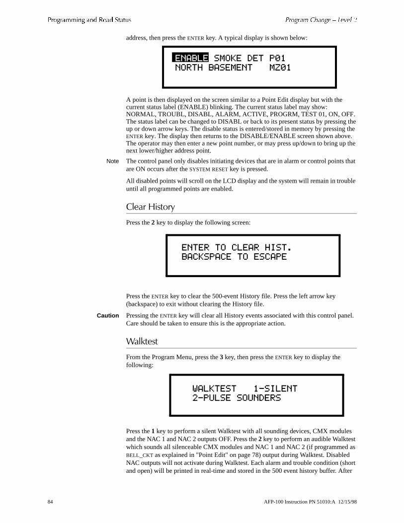
����������� ��� ��� ������ !����� �,���� 1 ��0�� 2
ng the g the e. p the
that
le
l.
s d as d ort
ter
address, then press the ENTER key. A typical display is shown below:
A point is then displayed on the screen similar to a Point Edit display but with the current status label (ENABLE) blinking. The current status label may show: NORMAL, TROUBL, DISABL, ALARM, ACTIVE, PROGRM, TEST 01, ON, OFF. The status label can be changed to DISABL or back to its present status by pressiup or down arrow keys. The disable status is entered/stored in memory by pressinENTER key. The display then returns to the DISABLE/ENABLE screen shown abovThe operator may then enter a new point number, or may press up/down to bring unext lower/higher address point.
Note The control panel only disables initiating devices that are in alarm or control pointsare ON occurs after the SYSTEM RESET key is pressed.
All disabled points will scroll on the LCD display and the system will remain in troubuntil all programmed points are enabled.
������8�����
Press the 2 key to display the following screen:
Press the ENTER key to clear the 500-event History file. Press the left arrow key (backspace) to exit without clearing the History file.
Caution Pressing the ENTER key will clear all History events associated with this control paneCare should be taken to ensure this is the appropriate action.
<��;��
From the Program Menu, press the 3 key, then press the ENTER key to display the following:
Press the 1 key to perform a silent Walktest with all sounding devices, CMX moduleand the NAC 1 and NAC 2 outputs OFF. Press the 2 key to perform an audible Walktestwhich sounds all silenceable CMX modules and NAC 1 and NAC 2 (if programmeBELL_CKT as explained in "Point Edit" on page 78) output during Walktest. DisableNAC outputs will not activate during Walktest. Each alarm and trouble condition (shand open) will be printed in real-time and stored in the 500 event history buffer. Af
���������������� �
��$������������( �
�������������$����
������������������
������������-�����
�-������������
84 AFP-100 Instruction PN 51010:A 12/15/98

!����� �,���� 1 ��0�� 2 ����������� ��� ��� ������
y A
and e o ause a report
uts VDC en
n hen ble
n all CD
pressing either '1' or '2', the screen shown below will appear:
If the ENTER key is pressed, the second line goes blank and the control panel is in Walktest mode. Walktest may be stopped at any time by pressing the left arrow ke(backspace), which returns the control panel to the “All Systems Normal” display. one hour time-out automatically returns the system to normal operation.
�#�����9����( ���������
When in Walktest, the control panel responds to each new alarm and activates itsprogrammed control outputs for four seconds, if those control outputs have been programmed for silenceable activation. It also stores each alarm in the history file printer with a 'TEST XX' status label. XX is a count of the number of times a devicwith this address has been tested. Note that this is a convenient way to identify twdetectors that are erroneously set to the same address. A complete Walktest will c'TEST 02' indication for the addresses to which both devices are set and no TEST for the address that one of the devices should have been set to.
Note If the system under Walktest includes one or more enabled MMX-2 modules, the following may apply:
If the MMX-2 module is used for a supervised, two-wire smoke zone, alarming anyMMX module in the system will result in the activation of programmed control outpfor an additional 8 seconds or less. This is caused by the temporary removal of 24resettable power from the MMX-2. The MMX-2 reports this loss of power as an opcondition in addition to the alarm condition.
%��� ���������
All intelligent devices on the SLC, as well as the two main circuit board NACs, aremonitored for fault conditions during Walktest mode. When a new trouble conditiooccurs, it activates all CMX modules programmed for Walktest and Bell Circuit 1, tshuts them off after an 8 second interval (4 seconds longer than alarms). The troustatus label is 'TEST T'.
While in Walktest, the trouble relay is on and the System Trouble LED flashes (as iof Program and Status change operations). The alarm relay is not activated. The Ldisplays the following:
�������������������
���������������
�������������������
AFP-100 Instruction PN 51010:A 12/15/98 85

����������� ��� ��� ������ !����� �,���� 1 ��0�� 2
he day
l ny p
ad
et to Slide
����� ������+��
From the Program Menu, press the 4 key to display the following screen:
The first digit of the hours is flashing and may be changed with the numeric pad. Tright arrow moves to the next digit. The up and down arrows select (A)M or (P)M, of the week, month, day and year. Pressing the ENTER key stores the time and date andreturns to the Level 2 screen.
�:��;
Program selection '5' performs a check on software zone assignments. The contropanel looks for output devices assigned to a software zone that does not contain ainput devices (detectors, monitor modules). If multiple devices fail the check, the uand down arrow keys are used to step through the list of devices. The user must return to point editing to correct any errors.
Note The system continues monitoring alarm conditions during all Programming and ReStatus operations with the exception of Walktest.
At the completion of system programming, switch SW1 (Write Protect) should be sthe Write Protect position to prevent inadvertent changes to programmed features.the switch to the up position to select the Write Protect feature.
�$�������������
� � ����� �� ����
86 AFP-100 Instruction PN 51010:A 12/15/98
er of an
key uent
the
SECTION 4 OPERATION
�������A���
-��������
Figure 45 shows the control keys on the control panel:
������ �� ������ <���
��;������#�2���
The ACKNOWLEDGE/STEP key silences the control panel sounder and changes all flashing LEDs to steady. Only one key press is necessary regardless of the numbnew alarms, troubles or supervisory signals. When the panel sounder is silenced,“Acknowledge” message is sent to the printer and the history file. Multiple active events are scrolled on the display at a three second rate. Acknowledge also automatically sends a “Silence Piezo” command to the LCD-2x20, AFM and LDMSeries annunciators.
When more than one event exists, the first press of the ACKNOWLEDGE/STEP key silences the panel sounder and changes all flashing LEDs to steady. The secondpress stops the scrolling and holds the event on the display for 1 minute. Subseqpressing of the key “steps” through each active event.
���� ��������
The ALARM SILENCE key performs the same functions as ACKNOWLEDGE/STEP key. In addition, if an alarm exists, it turns off all silenceable circuits and causes the AlarmSilence LED to turn on. It also sends an “Alarm Silenced” message to the printer,history file and the LCD-2x20. A subsequent new alarm will resound the system.
Note The ALARM SILENCE key operates on silenceable NAC outputs only.
/���� H���
AFP-100 Instruction PN 51010:A 12/15/98 87

� ������ ������� 3���
nd
sage e. It
+�����8����'����B
When the DRILL key is held for 2 seconds (time required to prevent accidental activations), the control panel turns on both control panel NAC outputs and all silenceable circuits (all control modules/NACs that are programmed silenceable) aturns off the ALARM SILENCE LED. The “Manual Evacuate” message is shown on theLCD display. The same message is sent to the printer and history file.
���� �*���
Pressing the SYSTEM RESET key turns off all control modules and NACs, temporarily turns off resettable power to 4-wire detectors, causes an “All Systems Normal” mesto be displayed on the LCD and stores “System Reset” in the printer and history filalso turns on all LEDs, panel sounder and LCD display segments as long as the SYSTEM RESET key is held (lamp test). Any alarm or trouble that exists after pressing the SYSTEM RESET key will resound the system.
88 AFP-100 Instruction PN 51010:A 12/15/98

����� ������ �4 ��������� � ������
l
nel.
such
ays
if
���� ������.+�-��������
-��������
The control panel has five System Status LED Indicators on the front of the contropanel. Figure 46 shows the system status LED indicators on the control panel:
������ �� ����� ���� /:( 4�������� <���
��������
This is a green LED which illuminates if 120 VAC power is applied to the control pa
���������
This is a red LED that flashes when one or more alarms occur. The FIRE ALARM LED illuminates steady when you press the ACKNOWLEDGE/STEP key or the ALARM SILENCE key. The FIRE ALARM LED turns off when you press the SYSTEM RESET key.
����������
This is a yellow LED that flashes when one or more supervisory conditions occur, as a sprinkler valve tamper condition. It illuminates steady when you press the ACKNOWLEDGE/STEP key or the ALARM SILENCE key. The SUPERVISORY LED turns off when you press the SYSTEM RESET key.
���� ��������
This is a yellow LED that turns on after the ALARM SILENCE key is pressed (preceded bya fire alarm condition). It turns off when you press the DRILL key or the SYSTEM RESET key.
���� ����)��
This is a yellow LED that flashes when one or more trouble conditions occur. It ston steady when the ACKNOWLEDGE/STEP key or ALARM SILENCE key is pressed. The LED turns off when all trouble conditions are cleared. This LED will also illuminatethe microprocessor watchdog circuit is activated.
������ ���� � @&�6��������
AFP-100 Instruction PN 51010:A 12/15/98 89

� ������ '���� ��������
mal' fer to
al
tc.
%�� �����������
With no alarms or troubles in the system, the display message is 'Systems All Noralong with the current time and date as shown below. To set the time and date, re"Set Time and Date" on page 86.
The control panel performs the following functions at regular intervals while in normmode:
• Polls all devices on the SLC, checking for valid reply, alarms, troubles, e
• Monitors the AC input voltage and the battery capacity
• Refreshes the LCD display and updates the system time
• Scans the keypad for entries
• Performs detector auto test
• Tests memory
• Update and reads the EIA-485 communications bus
����������������
� � ����� �� ����
90 AFP-100 Instruction PN 51010:A 12/15/98

er to age e is
o d, to
ical
ing
igit
r
ry
al
n
ics t
���)�����������
With no alarms, the detection of a trouble in the system will cause the panel soundsound, the System Trouble LED to flash and the trouble relay to activate. A messwill appear on the LCD display indicating the trouble condition. The same messagsent to the printer and history file along with time and date. A ground fault will alscause the yellow Ground Fault LED, located on the bottom of the main circuit boarturn on.
����� ���� �(�/� ������
For addressable Ionization or Photoelectric smoke detectors, the following is a typmessage that could appear on the LCD display for a detector in trouble.
The information displayed in the first line in the example above provides the followinformation:
• The type of event – in this example, TRBL indicates Device Trouble• The Specific Device Trouble for a Detector - the # symbol will be replace by a d
representing a specific trouble condition (refer to the list of Specific Device Troubles listed below)
• Type of device – in this example, SMOKE DET indicates smoke detector• Point type and address – in this example, P01 indicates Photoelectric detecto
assigned to address 01
The information displayed in the second line in the example above provides the following information:• <ADJ> – user programmed adjective descriptor from library list or custom ent
(five characters maximum)• <NOUN> – user programmed noun descriptor from library list or custom entry
(ten characters maximum)• Zone – zone to which the point is assigned
The # symbol in the display will be replaced by a digit that represents the Specific Device Troubles as listed in Table 12.
����� �� ������ ���� ������� ��� � ������
# Specific Device Troubles
1 An Invalid Reply may be due to:(1) incorrect pulse width received from a detector(2) no answer from a detector due to either a complete device failure or removfrom the SLC loop(3) an incorrect identification code received, i.e. a photo detector replaced by aion detector or vice-versa
2 Maintenance Alert - indicates that a detector has been within 80% of its alarm threshold for 24 hours, indicating that the detector needs cleaning
3 Fail Automatic Test - indicates that a detector's sensing chamber and electron(which are tested for normal safe operation every two hours) has failed the tes
�����+����������� �
%��&'%�'������(
AFP-100 Instruction PN 51010:A 12/15/98 91

� ������ ������� ��������
or
a e
ned
ry
.
file. age
������� ��� ������� ������
The following is a typical message that could appear on the LCD display for monitmodules and control modules in trouble.
The information displayed in the first line in the previous example provides the following information:
• The type of event – in this example TRBL indicates Device Trouble• The Specific Device Troubles for a module – the # symbol will be replaced by
digit representing a specific trouble condition (refer to the list of Specific DevicTroubles for a module below)
• Type of device – in this example, MONITOR indicates a monitor module• Point type and address – in this example, M01 indicates monitor module assig
to address 01
The information displayed in the second line in the previous example provides thefollowing information:
• <ADJ> – user programmed adjective descriptor from library list or custom ent(five characters maximum)
• <NOUN> – user programmed noun descriptor from library list or custom entry(ten characters maximum)
• Zone – zone to which the point is assigned
The # symbol in the display will be replaced by a digit that represents the SpecificDevice Troubles as listed in Table 13:
����� �� ������ ���� ������� ��� � ������
Pressing the ACKNOWLEDGE/STEP key will cause the panel sounder to silence and theSystem Trouble LED to turn on steady. This occurs regardless of the number of troubles, alarms and supervisory events active in the system (block acknowledge)When you press the ACKNOWLEDGE/STEP key, and at least one new alarm or trouble exists in the system, the “Acknowledge” message is sent to the printer and historyIf the trouble clears, either before or after Acknowledge, the “Clear Trouble” messis sent to the printer as illustrated by the following example:
CLR TRBL_# SMOKE DET P01 <ADJ><NOUN> ZONE# TIME and DATE
# Specific Device Troubles
1 An Invalid Reply may be due to:(1) incorrect pulse width received from a module(2) no answer from a module due to either a complete device failure or removal from the SLC loop(3) an incorrect identification code received, i.e. a monitor module replacedby a control module or vice-versa
2 Short Circuit Control Module - indicates a short circuit exists across a control module's NAC
3 Open Circuit Monitor/Control Module - indicates an open circuit exists on a control module’s NAC or the monitor module's Initiating Device Circuit
�����+������� �
%��&'%�'�����(
92 AFP-100 Instruction PN 51010:A 12/15/98

������� �������� � ������
tem, age is re
tem
ssed in
If all troubles clear and there are no supervisory or fire conditions active in the systhe system returns to normal operation status and the “Systems All Normal” messshown on the LCD display and stored in the history and printer files. Trouble restooccurs even if the troubles were never acknowledged (auto-restore).
If the ALARM SILENCE key is pressed when only troubles exist, it will have the sameeffect as the ACKNOWLEDGE/STEP key. The Alarm Silence LED will not be illuminatedunless there was also an alarm in the system.
Note If a combination of alarms, troubles and/or supervisory conditions occur in the syssimultaneously, only the alarms are scrolled on the display.
If multiple trouble conditions exist in the system, they scroll on the LCD display automatically at a 3-second rate. If the ACKNOWLEDGE/STEP key is pressed, the displaystops on the present item for one minute or until the Acknowledge/Step key is preagain. As the ACKNOWLEDGE/STEP key is pressed, the control panel displays events the following priority order:
6. Alarms in address order
7. Supervisories in address order
8. Troubles in address order
AFP-100 Instruction PN 51010:A 12/15/98 93
� ������ ���� ��������
���� ���������
Alarm operation is similar to trouble operation, but with the following differences:
• The panel sounder produces a steady output, not pulsed• The System Alarm (not Trouble) LED flashes• ALARM: device name, type and address are displayed• Alarms latch and are not allowed to clear automatically• Alarms activate software zones (control-by-event logic) if so programmed• Timers (Silence Inhibit, Auto-silence, Trouble Reminder) are started• Alarms activate the general alarm relay and zone Z00 (NAC 01 and NAC 02)• The trouble relay is not activated
A typical alarm display would be:
������������������� �
%��&'%�'�(��+
94 AFP-100 Instruction PN 51010:A 12/15/98
es:
zone. uits in ble
.
alarm A
d by
, it ) ped,
�������������������
Supervisory operation is similar to alarm operation but with the following differenc• The panel sounder is a warbling sound• The Supervisory LED (not Alarm) flashes• The Display Status label is Active• Supervisory relay is activated• Silenced alarms are not resounded• Timers are not started• The alarm relay is not activated
A typical Supervisory event would display:
Note that, like alarms, supervisory signals latch and can be assigned to a softwareSupervisory alarms do not cause resound as do other alarm conditions. Open circsupervisory wiring are processed by the control panel the same way as other trouconditions.
%����%������������������������� ���������
The control panel has two NACs: NAC 01 and NAC 02.
NAC 01 and NAC 02 are programmable. Both NACs may be either silenceable or nonsilenceable and may be programmed as steady or coded operations. Coded operation includes March Time, Temporal or California types. Refer to "Coded Operation - NAC 01 and NAC 02" on page 96, for additional information on coding
������0��0.�������. ��������
Each addressable detector and monitor module can be assigned to one software zone. Control modules may be assigned to a maximum of three software zones. general alarm zone (Z00) may be listed for output (control) points, but it is not necessary to list Z00 for input points, as this is the default zone. Z00 is not activatesupervisory points.
When an input device (detector, MMX series modules) alarms and is not disabledactivates all software zones assigned to it. An output device (CMX module or NACthat is not disabled is turned on when any of the software zones, to which it is mapbecome active.
Note For more information on CBE operation, refer to Appendix B, “Software Zones.”
����!���������� �
%��&'%�'�(��+
AFP-100 Instruction PN 51010:A 12/15/98 95
� ������ ������� ��������
tector
ng.
sing ble
,
efer
d day M.
tion
n,
+�������������
/��������������
Each detector is monitored by the control panel for its maintenance status. If a deis within 80% of its alarm threshold for a 24-hour period, a “maintenance alert” message will be automatically displayed, signaling that the detector needs servici
�� ����������������
An automatic test of each detector is performed every 2 hours. The detector's senchamber and electronics are functionally tested for normal, safe operation. A troumessage is displayed upon failure of this test. You can also clear this trouble by pressing the SYSTEM RESET key.
��������������������
The control panel monitors hardware device type codes (CPX, SDX, and FDX, MMX-1, MMX-101, MMX-2 and CMX) at slow intervals. Mismatch of any type codecompared to the system program, will cause a device trouble.
���� ����� �3����������
You can also program the control panel to perform alarm verification to detectors. Rto "Alarm Verification (None or Two Minutes)" on page 98, for a description of the Alarm Verification Timer.
������ ������������������ �
The control panel includes a crystal-based clock that provides time of day, date anof week. Time is displayed as 12 hour time with month/day/year and is stored in RAIf both AC and battery power are lost, the time must be reset.
���������������0�%�� 4&�����%�� 4'
Shown below are the pulse rate outputs via NAC 01 or NAC 02 when coded operais selected.
����� �� '�� � 0��� ��� )�� ����� ��������
Code Selection Pulse Rate
Continuous Continuous
March Time Pulses at 120 ppm (pulses per minute)
Temporal Code Pulses at ½ second On, ½ second Off, ½ second O½ second Off, ½ second On, 1½ seconds Off
California Code 10 seconds On, 5 seconds Off
96 AFP-100 Instruction PN 51010:A 12/15/98

!������� � ������
ing
ot anel
ot
�����#���
Presignal is used to delay output activation (control modules and NACs) while allowfor visual verification by a person. Once a detector or monitor module triggers an alarm, the panel sounder immediately, but the Notification Appliance Circuits are nactivated for 15 seconds. During this time, if the Acknowledge key is pressed, the psounder is silenced and the notification appliances will not activate for up to three minutes. After three minutes, the NACs will activate if the source of the alarm is ncleared. This does not affect monitor modules programmed as waterflow or supervisory. Presignal operation requires the approval of the local Authority HavingJurisdiction.
AFP-100 Instruction PN 51010:A 12/15/98 97
� ������ ������ ����� ����
e
fter
tion.
n ition
for a set.
nt the rent anel t the ts and
������������ ��� ���
��������-�:�)���� ����%�������$4��������
This option, if selected, prevents the ALARM SILENCE key from functioning for 60 seconds after an alarm. A new alarm during the initial 60 seconds will cause thtimer to restart with a new 60 seconds.
Note Silence Inhibit operation requires the approval of the local Authority Having Jurisdiction.
��0���������� ����%�������&4�/����
If Auto-silence is selected, the notification appliances are silenced automatically a10 minutes of activation. Pressing the DRILL key will restart the timer with a new 10 minutes.
Note Auto-silence operation requires the approval of the local Authority Having Jurisdic
���)���*� �����
If selected, this feature causes a reminding “beep” tone every 15 seconds during aalarm (after the Silence key is pressed) and every 2 minutes during a trouble cond(after the ACKNOWLEDGE/STEP key or ALARM SILENCE key is pressed). The “beep” tones from the panel sounder will occur until the alarm or fault is cleared.
���� �3������������%�����������/����
If alarm verification is selected, an addressable smoke detector's alarm is ignoredRetard period of 13 seconds and the detector's alarm condition is automatically reThere will be no alarm indication at the control panel during the Retard period. A Confirmation period of 1 minute and 47 seconds follows, during which a subsequealarm from the same detector will cause the control panel to immediately activate appropriate outputs and indicate the alarm condition at the control panel. If a diffedetector alarms any time during the first detector's verification period, the control pwill immediately activate all appropriate outputs and indicate the alarm condition acontrol panel. If no additional detector alarms occur within two minutes of the firstalarm (13 second retard plus 1 minute and 47 second confirmation), the timer resethe control panel is ready to verify any new detector alarms which may occur.
������ �$ �� =���������� ������
120 sec.13 sec.0 sec.
CONFIRMATIONRETARD
Alarm Ignored Control Panel Processes Alarm if Same Detector is Still in Alarm
Control Panel Immediately Processes Alarm
Detector Alarm Verification (Retard + Confirmation)
Detector Goes Into Alarm
Different Detector Alarms During First Detector's Verification Period
98 AFP-100 Instruction PN 51010:A 12/15/98

ent) ted
<�����������������������
If an alarm exists from a monitor module point that has a WATERFLOW type code, the Alarm Silence key will not function.
+���)��2.��)�����������
Input points which are disabled do not cause an alarm or any CBE (Control-By-Evactivity. Disabled output points are held in the off state. All disabled points are treaas if they were in trouble, with the exception being the status label that displays isDISABL.
AFP-100 Instruction PN 51010:A 12/15/98 99

� ������ ����� - *���
rol
�����$�<����#
If the SLC is wired and programmed for Style 6 and a single fault occurs, the contpanel will detect the fault and drive both ends of the line, fully recovering from the fault. The control panel latches the trouble and displays it until the SYSTEM RESET key is pressed. The display shows Style 6 trouble type.
100 AFP-100 Instruction PN 51010:A 12/15/98

#��� ������ � ������
to hile se
5:
that in
cel atus,
*�������
Read Status functions do not require a password. The control panel will continueprovide fire protection while in Read Status mode. Read Status may be entered wthe control panel is in alarm or trouble. If a new alarm or trouble occurs during thefunctions, the Read Status is exited to prevent confusion.
*��������.���
Press the ENTER key to display the programming menu on the LCD display:
To enter Read Status, press the 2 key. The control panel displays the following:
From the display shown above, you can take any of the functions listed in Table 1
����� �& 0��� ����� %��������
During all Read Status operations, except print operations, a 2-minute timer startscauses the control panel to return to the previous display if no key is pressed with2 minutes. Each key press restarts the 2-minute timer. Pressing the left arrow (backspace) key deletes the previous entry. (If there is no previous entry, it will canthe Read Status operation and return to the previous display.) To cancel Read Stpress the SYSTEM RESET key.
To Do this
Display Point Status Identify the type of device to be read by pressing the * key for a detector or the # key for a module. Key in the two-digit device address, then press the ENTER key.
Display Zone status Press the * key two times, key in the zone number (1–56), then press the ENTER key. To view the next or previous zone, press the Up or Down arrow keys.
Display System Parameters
Press the * key two times, then press the ENTER key.
Display Bell Circuit status
Press the * key, press the # key, press the 1 or 2 key, then press the ENTER key.
To display the 500-event History file one event at a time
Press the 1 key then press the ENTER key. Use the Up and Down arrow keys to step through the entries in the history file.
Print the program contents and current system status or the history file
Press the 2 key, then press the ENTER key. A new menu appears which prompts the user to press '1' to print Program/Status or '2' to print History file
�����������
��������������������
������������*�+"���
$�����������������
AFP-100 Instruction PN 51010:A 12/15/98 101

� ������ #��� ������
fter e next e 1-99, d 5)
r
oint
er
ory
g status.
age
age
+�����������
Display Point operations display addressable device status on the LCD display. Athe status of the device displays, press the Up arrow key to display the status of thhighest addressable device or press the Down arrow key to display the status of thprevious addressable device. The sequence of display point is 1) Detector points 02) Module points 01-99, 3) NAC bell circuits 01 and 02, 4) System Parameters, anZones 1-56.
A typical Read Status display is as follows:
In the preceding display:
• NORMAL is the present status (could be ALARM, TRBL_#, DISABL, etc.)
• SMOKE (DET) is the device type; P indicates that this is a photoelectric detecto(could be I if ionization or PULL BOX, HORN CKT, etc.) and 01 is the device address
• WEST HALLWAY is the custom label programmed for this device
• MZ56 is the assigned software zone
If the point is not installed, a Read Status command to that point will result in a NOT INSTALLED message on the display.
*����8�����
The control panel provides a history file that can store up to 500 events, such as PStatus, System Troubles, and Acknowledge/Step, Alarm Silence, Drill and SystemReset key presses. All history events are recorded with the time and date.
History events are stored in volatile memory, therefore, removal of primary AC powand secondary battery power will clear the history buffer. To clear the History file without removing power, see"Clear History" on page 84. To view events in the histfile, use the Up and Down arrow keys to step through the events.
��������#��
You can use Print Program function to print all user-programmed options, includindevice types, software zone assignments, system parameters, and current system
Note For instructions on connecting a printer, refer to “Printer/PC Interface Module” on p64.
�����8�����
You can use Print Program function to print the entire 500-event history file.
Note For instructions on connecting a printer, refer to“Printer/PC Interface Module” on p64.
��������������� �
�����$�����������(#.
102 AFP-100 Instruction PN 51010:A 12/15/98

ircuit, e of red
nel.
APPENDIX A POWER SUPPLY CALCULATIONS
�:����������:������
The control panel requires connection to a separate dedicated 120 VAC branch cwhich must be labeled “Fire Alarm.” The branch circuit must connect to the line sidthe main power feed of the protected premises. No other equipment may be powefrom the fire alarm branch circuit. The branch circuit wire must run continuously, without any disconnect devices, from the power source to the fire alarm control paOvercurrent protection for this circuit must comply with Article 760 of the National Electrical Code as well as local codes. Use #14 AWG (2.00 mm2) wire with 600 volt insulation for this branch circuit.
Use Table 16 to determine the total amount of current, in AC amps, that must be supplied to the fire alarm system.
����� �4 �� +���# ������ 0�:����(��� ; ��2<��
Unit TypeNumber of Units
Current Draw (amps)
Total Current per Device
AFP-100 1 X 2.3 = 2.3
CHG-120 Charger [ ] X 2.0 =
Total AC Branch Current Required = amps
AFP-100 Instruction PN 51010:A 12/15/98 103

��� ���� ��� �����
ting ) to y.
h each
������������� �����
The AFP-100 provides filtered power for operating the fire alarm control panel, operating external devices and operating the standby battery. The power for operaexternal devices is limited. Use Table 1 (standby or nonalarm) and Table 2 (alarmdetermine if external loading is within the capabilities of the AFP-100 power suppl
Concerning smoke detectors: refer to the manufacturer's data sheet packaged witsmoke detector to find the standby and alarm current draws to use in the followingtables. Make sure to power detectors from TB4, terminals 5 and 6.
����� � ������ ��� � ������ � ������� ������ �������� � ��� ����
Notes:
1. TB4, terminals 1 and 2; nonregulated 24 VDC, 2.5 amps
2. TB4, terminals 3 and 4; filtered 24 VDC +/-5% 120Hz ripple @ 10 mVRMS
3. TB4, terminals 5 and 6; filtered 24 VDC +/-5% 120Hz ripple @ 10 mVRMS
4. TB4, terminals 3 and 4; nonresettable auxiliary power, 300 mA
Device Type # of DevicesStandby Current (amps)
Total Current (amps)
Main Circuit Board 1 X 0.08 = 0.08
Fire•Lite RTM-8F [ ] one max. X 0.009 =
ACM-8R [ ] X 0.030 =
AFM-16ATAFM-32A
[ ] one max. X 0.04 =
AEM-16ATAEM-32A
[ ] X 0.002 =
AFM-16ATAFM-32A
[ ] X 0.04 =
AFM-16A [ ] X 0.025 =
UDACT [ ] one max. X 0.04 =
LDM-32 [ ] X 0.04 =
LDM-E32 [ ] X 0.002 =
LCD-2x20 Series [ ] X 0.054 =
4-Wire Smoke Detector [ ] X [ ] =
Power Supervision Relay [ ] X 0.025 =
CPX Series detectors [ ] X 0.00015 =
SDX Series detectors [ ] X 0.00015 =
FDX Series detectors [ ] X 0.0002 =
MMX-1 [ ] X 0.0002 =
MMX-101 [ ] X 0.0002 =
MMX-2 [ ] X 0.007 =
BG-10LX [ ] X 0.0002 =
CMX [ ] X 0.0002 =
ISO-X [ ] X 0.0004 =
Auxiliary Devices Powered from TB4
[ ] X [ ] =
Sum Column for Standby Load =
AFP-100 Instruction PN 51010:A 12/15/98 1

��� ���� ��� �����
5. TB4, terminals 5 and 6; resettable smoke detector power, 300 mA
6. Refer to Current Limitations on following page
����� � ������ ��� � ����� � ������� ������ �������� � ��� ��� �������
Device Type # of DevicesAlarm Current (amps)
Total Current 1 (amps)
Main Circuit Board 1 X 0.168 = 0.168
Fire•Lite RTM-8F [ ] one max. X 0.1462 =
ACM-8R [ ] X 0.1583 =
AFM-16ATAFM-32A
[ ] one max. X 0.0564 =
AEM-16AAEM-32A
[ ] X 0.018d =
AFM-16ATAFM-32A
[ ] X 0.0564 =
AFM-16A [ ] X 0.0654 =
UDACT [ ] one max. X 0.0755 =
LDM-32 [ ] X 0.0566 =
LDM-E32 [ ] X 0.018s =
LCD-2x20 Series [ ] X 0.054 =
4-Wire Smoke Detector [ ] X [ ] =
Power Supervision Relay [ ] X [ ] =
Addressable Devices maximum draw for all devices
X 0.27 = 0.2
Notification Appliances [ ] X [ ] =
Auxiliary Devices Powered from TB4
[ ] X [ ] =
Sum Column for Alarm Load = amps8
1. Current limitations of terminals:TB4, terminals 1 and 2 = 2.5 ampsTB4, terminals 3 and 4 = 0.3 ampsTB4, terminals 5 and 6 = 0.3 ampsTB1 and TB2, any one circuit = 2.5 ampsTotal current draw from all terminals cannot exceed 3.6 amps with standard XRM-1 transformer installed; 6.0 amps with both standard XRM-1 transformer and optional XRM-24 transformer installed. Note that total current from TB4, terminals 3 and 4 and terminals 5 and 6 must not exceed 0.600 amps.
2. All Fire•Lite RTM-8F Relays activated.3. All eight ACM-8R Relays activated on a single module.4. All annunciator LEDs on.5. UDACT actively making phone call to Central Station. If the normally open contact is used, current
consumption increases to 100 mA.6. LDM-32 with LEDs on7. MMX-2 Monitor Module current-limited at 90 mA in alarm.8. This column must not exceed total system current draw of 6.6 amps.
2 AFP-100 Instruction PN 51010:A 12/15/98

���� �� �� ������������ �,� ��� !�"�� ������
����� �8 +�����" ����������
Notes:
1 Up to 12 AH batteries can be located in the AFP-100 backbox.
2 12 AH to 18 AH batteries require the Notifier BB-17 battery box.
3 The AFP-100 main circuit board allows disabling of AFP-100 battery charger if using the CHG-120 Battery Charger for 25 AH to 100 AH batteries (requires separate housing).
Standby Load Current (amps)[ ]
X Required Standby Time in Hours (24 or 60 Hours)[ ]
= __________
Alarm Load Current (amps)[ ]
X Required Alarm Time in Hours (5 minutes = 0.084)[ ]
= __________
Add Standby and Alarm Load for Required Ampere Hour Battery
= __________
Multiply by the Derating Factor or 1.2 X 1.2 __________
Total Ampere Hours (AH) Required = __________
106 AFP-100 Instruction PN 51010:A 12/15/98

tem. ons, ed ect
sable
l
um ically f one
d to a to a
nitor es of ot
APPENDIX B SOFTWARE ZONES
��������������������C����
Setup and configuration of an addressable system differs from a conventional sysIn a conventional system, assignment of input devices (smoke detectors, pull statiheat detectors, etc.) to zones is straightforward. Wiring is direct from clearly markcontrol panel terminals to any device assigned to a particular zone. Connection ofoutput devices (horns, bells, strobes, etc.) in a conventional system is done by dirwiring of the output device to terminals marked 'bell'.
With addressable systems, the same pair of wires is used to connect to all addresinput and output devices. Communications between the control panel and all addressable devices takes place over one pair of wires originating from the contropanel. Software programming is used to configure the system, versus direct wiring. Zone assignment is created via software means, hence the term 'software zones'.
Setup of an AFP-100 software zone is straightforward. Any zone may have a minimof one and a maximum of 99 addressable input devices. Each detector is automatassigned to a general alarm output (zone Z00). A zone may also have a minimum oand a maximum of 99 addressable output devices. CMX modules can be assignemaximum of three software zones. Detectors and MMX modules can be assignedmaximum of two software zones.
Use the charts on the following pages to help in 'zoning' the system. Note that moand control modules make up one group of 99 addresses. It is critical that addressdetectors are not duplicated and that monitor and control module addresses are nduplicated.
AFP-100 Instruction PN 51010:A 12/15/98 107

������� ���� 4������ �� ����"��� 5����
two
.7� ����������������C����
In the example in Figure 48 on the following page, Software Zones are zoned as follows:
Software Zone 1 has the following addressable devices assigned to it:
• Two SDX photoelectric detectors with addresses “01” and “02”
• One MMX-1 module with address “01”
• Three CMX modules with addresses “03”, “04” and “05”
Software Zone 2 has the following addressable devices assigned to it:
• Two CPX ionization detectors with addresses “03” and “04”
• One MMX-101 module with address “02”
• Three CMX modules with addresses “03”, “06” and “07”
• One SDX photoelectric detector with address “05”
Software Zone 3 has the following addressable devices assigned to it:
• Two SDX photoelectric detectors with addresses “05” and “06”
• One CPX ionization detector with address “07”
• Three CMX modules with addresses “03”, “08” and “09”
Figure 48 shows some of the key assignment features of the control panel:
• Addresses of detectors and addresses of MMX and CMX modules are not duplicated
• The CMX module at address “03” is assigned to the maximum three software zones (providing for floor above and floor below).
• The SDX photoelectric detector at address “05” is assigned to the maximum ofsoftware zones (providing a special action like elevator recall)
• Detectors and MMX modules are assigned to one software zone
Note Make sure to properly plan the installation before installing any devices.
108 AFP-100 Instruction PN 51010:A 12/15/98

���������� �� ������ ��� ������� �� 5���� ������� ����
��������������-��������������C����
Figure 48 shows examples of software zones for inputs and outputs.
������ �% ���&�� >����� :;�� ��
SDX 01
SDX 02
MMX-1 01
CMX 05
CMX 04
ZONE 01
MMX-101 02
CPX 03
CPX 04
CMX 07
CMX 06
CMX 03
ZONE 02
SDX 05
SDX 06
CPX 07
CMX 09
CMX 08
ZONE 03
����� �� ���
�������� �����
������ �� ���
AFP-100 Instruction PN 51010:A 12/15/98 109

������� ���� ����� !������� �,����
�� �������#�� ��#��:���
Table 20 contains a sample programming sheet for detectors.
����� �2 ������ '�����((��� �#��� 3�(���
DETECTOR ZONE ASSIGNMENT
AddressDevice Type
Zone Number
ADJ (5 charact. max)NOUN (9 charact. max)
AddressDevice Type
Zone Number
ADJ (5 charact. max)NOUN (9 charact. max)
01 SDX 1 FIRST HALL 5102 SDX 1 ELEV. LOBBY 5203 CPX 2 2ND FLOOR 5304 CPX 2 ROOM 210 5405 SDX 3 3RD FLOOR 5506 SDX 3 MEZZANINE 5607 CPX 3 MECH. ROOM 5708 SDX 1, 2 Z02 OFFICE 5809 5910 6011 6112 6213 6314 6415 6516 6617 6718 6819 6920 7021 7122 7223 7324 7425 7526 7627 7728 7829 7930 8031 8132 8233 8334 8435 8536 8637 8738 8839 8940 9041 9142 9243 9344 9445 9546 9647 9748 9849 9950
110 AFP-100 Instruction PN 51010:A 12/15/98
Table 21 contains a sample programming sheet for modules:
����� �� ������ '�����((��� �#��� 3�(���
MONITOR/CONTROL MODULE ZONE ASSIGNMENT
Address
Device Type
Zone Number
ADJ (5 charact. max)NOUN (9 charact. max)
AddressDevice Type
Zone Number
ADJ (5 charact. max)NOUN (9 charact. max)
01 MMX-1 1 WEST HALL 5102 MMX-101 2 EAST STAIRWELL 5203 CMX 1, 2, 3 2ND FLOOR 5304 CMX 1 1ST FLOOR 5405 CMX 1 EAST HALL 5506 CMX 2 ELEV. LOBBY 5607 CMX 2 MEZZANINE 5708 CMX 3 3RD FLOOR 5809 CMX 3 MECH. ROOM 5910 MMX-101 2, 3 Z03 CLOSET 6011 6112 6213 6314 6415 6516 6617 6718 6819 6920 7021 7122 7223 7324 7425 7526 7627 7728 7829 7930 8031 8132 8233 8334 8435 8536 8637 8738 8839 8940 9041 9142 9243 9344 9445 9546 9647 9748 9849 99
50
AFP-100 Instruction PN 51010:A 12/15/98 111
������� ���� ����� !������� �,����
������ �' � �? >����� 3���
Input Devices Zones Output Devices
112 AFP-100 Instruction PN 51010:A 12/15/98

DETECTOR ZONE ASSIGNMENT
AddressDevice Type
Zone Number
ADJ (5 charact. max)NOUN (9 charact. max)
AddressDevice Type
Zone Number
ADJ (5 charact. max)NOUN (9 charact. max)
01 5102 5203 5304 5405 5506 5607 5708 5809 5910 6011 6112 6213 6314 6415 6516 6617 6718 6819 6920 7021 7122 7223 7324 7425 7526 7627 7728 7829 7930 8031 8132 8233 8334 8435 8536 8637 8738 8839 8940 9041 9142 9243 9344 9445 9546 9647 9748 9849 9950
AFP-100 Instruction PN 51010:A 12/15/98 113
������� ���� ����� !������� �,����
MONITOR/CONTROL MODULE ZONE ASSIGNMENT
AddressDevice Type
Zone Number
ADJ (5 charact. max)NOUN (9 charact. max)
AddressDevice Type
Zone Number
ADJ (5 charact. max)NOUN (9 charact. max)
01 5102 5203 5304 5405 5506 5607 5708 5809 5910 6011 6112 6213 6314 6415 6516 6617 6718 6819 6920 7021 7122 7223 7324 7425 7526 7627 7728 7829 7930 8031 8132 8233 8334 8435 8536 8637 8738 8839 8940 9041 9142 9243 9344 9445 9546 9647 9748 9849 9950
114 AFP-100 Instruction PN 51010:A 12/15/98

n a -1) rs by
ifier
APPENDIX C LCD-2X20 SERIES ANNUNCIATOR WIRING
��������
Figure 50 illustrates the wiring of two LCD-2x20 Series Remote Annunciators to aAFP-100. A maximum of 32 LCD-2x20 Series annunciators may be connected tosingle control panel. The EIA-485 wiring must pass through a ferrite core (PN FBDin each LCD-2x20 Series. Figure 50 also shows power supplied to the annunciatothe AFP-100. For system applications requiring greater than the 300 mA of nonresettable power the AFP-100 can supply or for remote locations, use the NotFCPS-24 Field Charger Power Supply.
AFP-100 Instruction PN 51010:A 12/15/98 115

������ ���� !���������� "����� *���
t the
ctor ole at the
<����#
The DIM-485 interface module is required when using the LCD-2x20 Series. Inserplastic standoff, supplied with the DIM-485, into the hole located near the J11 connector on the top right side of the AFP-100 main circuit board. Align the conneon the DIM-485 board with J11 on the AFP-100 main circuit board and align the hon the DIM-485 with the standoff inserted into the main circuit board. Carefully sethe DIM-485 connector on the main circuit board J11 connector and press to seatDIM-485 on the standoff.
������ �# /�("-;-# ����� 0�����
@/�,-D-! ������ �� � ����
@/�,-D-! ������ �� � ���� �D
4������ /�� (0 4%�,� ��C ����
4������ /�� (0 4%�,���C ����
&6�,.32
DIM-485 J11
-. 9�/ 5%.��������� : �<���� . �=�
�4(,�!! �� � ���� �D
Earth Ground- optional shield connection
(+) (–) 24 VDC Out
n/c
(+) 24 VDC IN(-) 24 VDC
(+) EIA-485 IN(-) EIA-485
(+) (-) EIA-485 Out
DIM-485 Connections
DIM-485 LCD-403 Series
Terminal 1 - Out (+) P1 Terminal 2
Terminal 2 - In (+) P1 Terminal 12
Terminal 3 - Out (-) P1 Terminal 4
Terminal 4 - In (+) P1 Terminal 32
Notes:
1. The table above shows terminal to terminal wiring between the DIM-485 and one LCD-2x20 Series Annunciator.
2. If more than one LCD-2x20 Series is installed, the wiring to the DIM-485 In (+) Terminal 2 and In (-) Terminal 4 will be from the Out terminals of the last installed LCD-2x20 Series Annunciator
3. The LCD-2x20 Series must have the two supplied R120 (120 ohm) resistors installed across the In Terminals 2 and 4 and Out terminals 1 and 3. These resistors are required for impedance matching.
4. Refer to the LCD-2x20 Series Technical Manual Document 51105 for detailed wiring information.
116 AFP-100 Instruction PN 51010:A 12/15/98

ng
00. the
APPENDIX D ANNUNCIATOR WIRING
��������
The following illustrations show the various configurations which may be wired usiAFM and ACM Series Annunciators. LDM Series Annunciators may be used in a similar manner. All illustrations show power supplied to annunciators by the AFP-1For system applications requiring greater than the 300 mA of nonresettable powerAFP-100 can supply, use the Notifier FCPS-24 Field Charger Power Supply.
AFP-100 Instruction PN 51010:A 12/15/98 117

!���������� "����� *��� �����
set h to
<����#�+��#�� �
The following figure shows a configuration which provides 56 zones of alarm and trouble indications, remote Acknowledge/Step, Alarm Silence, Drill and System Rekeys, System Supervisory, AC Fail, and Trouble indications. Use AKS-1 keyswitcprevent unauthorized actuation of control switches. Refer to the ACS Manual for further details.
�/+,�>�5 �&+,�>�5 �&+,�>�5 �&+,�>�5
Ribbon Cable
Ribbon Cable
Ribbon Cable
3 8��� ������ ��� 5� ����. ����$�� 6�/H# �6@# ��6@@#�&�&5�# ������ 5� ��� @&�#)�,@����)"",@��� (�� @&�#(��O � ����
�> 8�� ������ ���5� ����
�> 8�� ������ ���5� ����
�> 8�� ������ ���5� ����
Ribbon Cable
Ribbon Cable
Ribbon Cable
Annunciator Power - 12 to 18 AWG
2-wire EIA-485 circuit - max. 6,000 ft. @ 16 AWG
#��� --
���� /�� ������� (���&6�,.32 P -!H %� �
118 AFP-100 Instruction PN 51010:A 12/15/98

le e
The following configuration provides 56 zones of alarm indication, a System TroubLED, an On Line/Power LED, local panel sounder and a local Silence/Acknowledgswitch.
The following configuration provides 16 alarm and trouble LEDs, System Trouble LED, On Line/Power LED, local Silence/Acknowledge, Drill and Reset remote switches and panel sounder. Only one per system.
The following configuration provides 32 alarm LEDs, On Line/Power LED, SystemTrouble LED and local Silence/Acknowledge switch. Only one per system.
�/+,:-� �/+,:-�
�����/����
�4(,�!!
#��� --
�4+,�>�5
�4+,:-�
#��� --
AFP-100 Instruction PN 51010:A 12/15/98 119
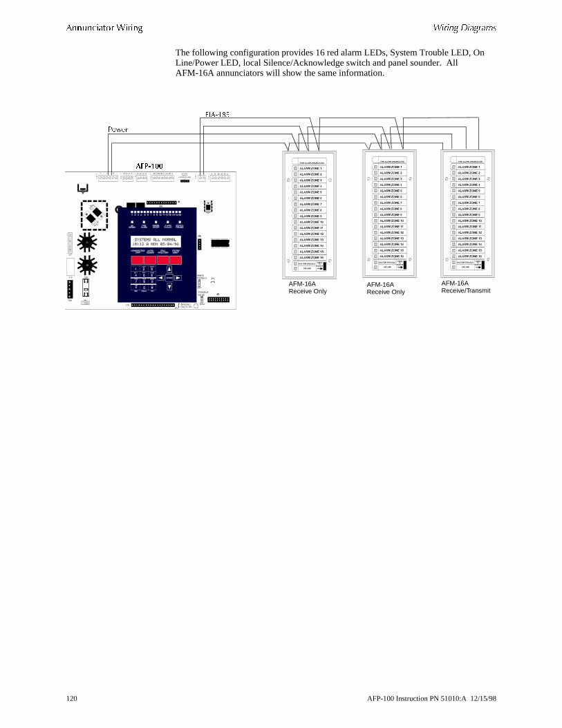
!���������� "����� *��� �����
The following configuration provides 16 red alarm LEDs, System Trouble LED, OnLine/Power LED, local Silence/Acknowledge switch and panel sounder. All AFM-16A annunciators will show the same information.&6�,.32
(��
#��� --
AFM-16AReceive Only
AFM-16AReceive Only
AFM-16AReceive/Transmit
120 AFP-100 Instruction PN 51010:A 12/15/98

*��� ����� !���������� "�����
me 56 set).
The following configuration allows the annunciation of 56 zones on the first two annunciators. 56 zones are annunciated on the second four annunciators. The sazones are annunciated on the last four annunciators (which duplicate the previous
Ribbon Cable
Ribbon Cable
Ribbon Cable
�/+,:-� �&+,:-�
�����/����
#��� --
Ribbon Cable
Ribbon Cable
Ribbon Cable
�/+,�>�5 �&+,�>�5 �&+,�>�5 �&+,�>�5
�/+,�>�5 �&+,�>�5 �&+,�>�5 �&+,�>�5
�����?� )���0 /���� ����$��
�����?� )��������� ����$����Q� 4 �����
�����?��5�������/���� ����$��4 �����
AFP-100 Instruction PN 51010:A 12/15/98 121

!���������� "����� *��� �����
�����
122 AFP-100 Instruction PN 51010:A 12/15/98

ction
d
ted
APPENDIX E NFPA STANDARD-SPECIFIC REQUIREMENTS
��������
The AFP-100 is designed for use in commercial, industrial and institutional applications and meets the requirements for service under the National Fire ProteAssociation (NFPA) Standards outlined in this Appendix. The minimum system components required for compliance with the appropriate NFPA standard are listebelow:
• AFP-100 Control Panel Contains the main control board, cabinet (backbox anddoor), main power supply transformer and power supply.
• Batteries Refer to “Appendix A”, for Standby Power Requirements.
• Initiating Devices Connected to one of the control panel's Initiating Device Circuits.
• Notification Appliances Connected to the control panel's Notification ApplianceCircuit via a control module.
The following additional equipment if needed for compliance with the NFPA 72 standards listed below:
)*'� 5� )������� *��� ����( �������� ���= Fire Alarm Systems for Central Station Service (Protected Premises Unit) and Remote Station Service requires:
• MS-5012 for connection to a compatible listed Central Station DACR or ProtecPremises Receiving Unit. This unit must be installed as outlined in Figure 51, “Central Station Service Using MS-5012,” on page 125.
OR
• UDACT may be installed as illustrated in Figure 39, “External UDACT Connections,” on page 58.
AFP-100 Instruction PN 51010:A 12/15/98 123

#$�! ���������� ����� �%������� �0��0�"
e
53, ion
ling
)*'� 5� ��3�����" *��� ����( �" ��( Fire•Lite RTM-8F Relay/Transmitter Module for connection to a compatible listed Local Energy Municipal Box. This unit must binstalled as outlined in Figure 52, “Municipal Box Connected to Fire•Lite RTM-8F Relay Transmitter Module,” on page 126.
)*'� 5� 0�(��� ������� *��� ����( �" ��( Fire•Lite RTM-8F Relay/Transmitter Module for connection to the Notifier RS82 Remote Station Receiver. See Figure “NFPA 72 Remote Station Protective Signaling System,” on page 127, for installatinstructions for this unit.
)*'� 5� '���������" *��� ����( �" ��( AFP-100 Alarm, Trouble and Supervisorycontacts connected to Transmitter(s). See Figure 54, “Proprietary Protective SignaSystem,” on page 128, for installation instructions for this unit.
124 AFP-100 Instruction PN 51010:A 12/15/98
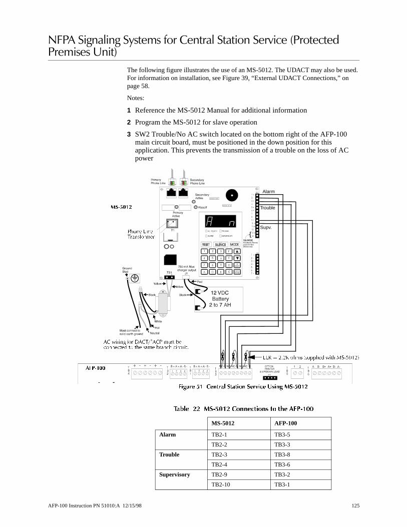
ed.
%������#�����#����� ��������������������������������������� �����5��
The following figure illustrates the use of an MS-5012. The UDACT may also be usFor information on installation, see Figure 39, “External UDACT Connections,” on page 58.
Notes:
1 Reference the MS-5012 Manual for additional information
2 Program the MS-5012 for slave operation
3 SW2 Trouble/No AC switch located on the bottom right of the AFP-100 main circuit board, must be positioned in the down position for this application. This prevents the transmission of a trouble on the loss of ACpower
������ �� ����� ����� ��9��� .���� �"�#�-
&@� A -;-H $�� �� ������ ��$ +�,2!�-�
�/ ���� "� ��/5�4�/( � �� ���������� � �$� ���� �����$ ���� ��;
#��� --
.��6- �
($�� @���5����"����
Alarm
Trouble
Supv.
����� �� ��$&2�� ��������� �� �#� �*'$�22
MS-5012 AFP-100
Alarm TB2-1 TB3-5
TB2-2 TB3-3
Trouble TB2-3 TB3-8
TB2-4 TB3-6
Supervisory TB2-9 TB3-2
TB2-10 TB3-1
AFP-100 Instruction PN 51010:A 12/15/98 125
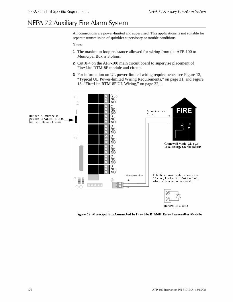
#$�! ���������� ����� �%������� '�!� 62 ������� ��� ���� �����
for
, e
%����>'��7���������������� �����
All connections are power-limited and supervised. This applications is not suitableseparate transmission of sprinkler supervisory or trouble conditions.
Notes:
1 The maximum loop resistance allowed for wiring from the AFP-100 to Municipal Box is 3 ohms.
2 Cut JP4 on the AFP-100 main circuit board to supervise placement of Fire•Lite RTM-8F module and circuit.
3 For information on UL power-limited wiring requirements, see Figure 12“Typical UL Power-limited Wiring Requirements,” on page 31, and Figur13, “Fire•Lite RTM-8F UL Wiring,” on page 32, .
������ �- ������� ��; ��������� �� ����2/��� ,��"%� ,� � ���������� ���� �
FIRE
5����� .��� .���6!1���� 7��) .����� �� ��8
(�������� �$� �� ����� ��������� ��� ��� ��$ � �0.!!. ����$�� � �������� �� �����
5���������� ) �� �
+
-
Nonpower-lim-
+ ������� %D/��� �� +
-
' ���� '(- � �� �� �������� 17 .$�"�1 �&/"� �� �� �$�� ����������
126 AFP-100 Instruction PN 51010:A 12/15/98
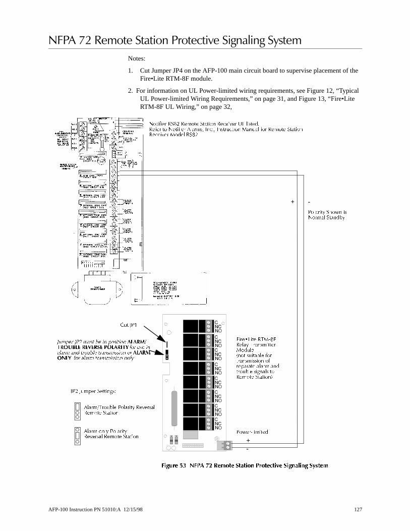
f the
al
%����>'�*� ��������������������#�����#�����
Notes:
1. Cut Jumper JP4 on the AFP-100 main circuit board to supervise placement oFire•Lite RTM-8F module.
2. For information on UL Power-limited wiring requirements, see Figure 12, “TypicUL Power-limited Wiring Requirements,” on page 31, and Figure 13, “Fire•LiteRTM-8F UL Wiring,” on page 32,
������ �� ��! $- ,����� ����� !�������9� ��� ��� �����
0��"��� ��3- ����� ������ �����?�� K@ ������;��"�� � 0��"��� ������# 6��;# 6���� ���� +�� �� "� ����� �����������?�� +��� ��3-;
+ -
(������ �$� ��0���� �������
4���M@��� �5+,34����� 5����������+� ����� � ������ "������������ "�������� ����� ����� ��� �� ���� ������ �������
/ � '(�
��!� "� ���� � �� !������� #1#�.���&$�17 �747��7 �&1#�%�9 ��� �� ������� ��� ������ ������������ �� #1#�.&�19 ��� ����� ������������ ����
'(- ' ���� ������ ��
������5� ��� (������ ��?���������� ������
����� ��� (��������?����� ����� ������
+-
(��,�������
AFP-100 Instruction PN 51010:A 12/15/98 127

#$�! ���������� ����� �%������� '�!� 62 !��������� !������0� ������� ������
ary
%����>'�����������������������#�����#����� �
Notes:
1. Connection between the AFP-100 and the transmitter are supervised by the transmitter.
2. This AFP-100/Transmitter arrangement can be employed for NFPA 72 ProprietProtective Signaling System.
������ �� !��������� !�������9� ��� ��� �����
4��,� ����� ������ �� ������� ����?��� � � ���?�����������;
4��,/ 5� ��� ������ $��$��� � ���������� ����?��� ���� 5� ��� �������;
4��,/ ����� �������� ������ � ����?���� B������ �����;
#��� -- .��� ����
#��� -- #������� �� "����� ����
128 AFP-100 Instruction PN 51010:A 12/15/98

l ches
efully re, w to
c
APPENDIX F WIRE REQUIREMENTS
��������
T-tapping of the SLC wiring is allowed for 2-wire (Style 4) configurations. The totaresistance of any branch cannot exceed 40 ohms. The total wire length of all brancannot exceed 10,000 feet (3,000 m).
Connecting external system accessories to the AFP-100 main circuits must be carconsidered to ensure proper operation. It is important to use the correct type of wiwire gauge and wire run length for each AFP-100 circuit. Reference the chart belospecify wire requirements and limitations for each AFP-100 circuit.
Note If the SLC is to be run in conduit with Notification Appliance Circuits, the risk of encountering problems can be greatly reduced by exclusively employing electronisounders (such as MA/SS-24D) instead of more electronically noisy notification appliances such as electromechanical bells or horns.
AFP-100 Instruction PN 51010:A 12/15/98 129

"�� �%������� �0��0�"
The following table contains wire requirements for the AFP-100:
����� �� �*'$�22 -��� �����������
CIRCUIT CONNECTIONS WIRE REQUIREMENTS
Circuit TypeCircuit Function
Wire Type and Limitations
Recommended Max. DistanceFeet (meters)
Wire Gauge and Compatible Brands
SLC (power-limited)
Connects to Addressable Devices
Twisted, shielded pair, 40 ohms maximum per length of Style 6 and 7 loops. 40 ohms per branch maximum for Style 4
loops1
10,000 (3,000 m)8,000 (2,400 m)4,875 (1,450 m)3,225 (980 m)
12 AWG (3.25 mm2): Genesis 4410, Signal 98230, Belden 9583, WPW999
14 AWG (2.00 mm2):Genesis 4408 & 4608 Signal 98430, Belden 9581, WPW995
16 AWG (1.30 mm2):Genesis 4406 & 4606 Signal 98630, Belden 9575, WPW991
18 AWG (0.75 mm2):Genesis 4402 & 4602 Signal 98300, Belden 9574, WPW975
Untwisted, unshielded pair 1,000 (300 m) 12-18 AWG (3.25 - 0.75 mm2)
EIA-485(power-limited)
Connects to annunciator modules
Twisted, shielded pair with a characteristic impedance of 120 ohms
6,000 (1,800 m) 18 AWG (0.75 mm2)
EIA-232(power-limited)
PIM-24 output connects to remote printer and PC computer
Twisted, shielded pair 50 (15 m) 18 AWG (0.75 mm2) minimum
MMX-1 and MMX-101(power-limited)
Initiating Device Circuit
Maximum loop wire resistance is 40 ohms for the MMX-1 and 20 ohms for the MMX-101
2,500 (760 m) 12-18 AWG (3.25 - 0.75 mm2)
MMX-2(power-limited)
Initiating Device Circuit
No more than a 2.4 volt drop allowed at end of circuit. Maximum loop wire resistance is 25 ohms
2,500 (760 m) 12-18 AWG (3.25 - 0.75 mm2)
CMX(power-limited)
Notification Appliance Circuit
In alarm, no more than a 1.2 volt drop allowed at end of circuit
Distance limitation set by 1.2 volt maximum line drop
12-18 AWG (3.25 - 0.75 mm2)
24 VDC filtered resettable and nonresettable(power-limited)
Connects to annunciators and other accessories
No more than 1.2 volt drop allowed from supply source to end of any branch
Distance limitation set by 1.2 volt maximum line drop
12-18 AWG (3.25 - 0.75 mm2)
24 VDC nonregulated(power-limited)
Connects to CMX control modules and accessories
No more than 1.2 volt drop allowed from supply source to end of any branch
Distance limitation set by 1.2 volt maximum line drop
12-18 AWG (3.25 - 0.75 mm2)
CHG-120 Remote secondary power source
12 AWG (3.25 mm2) in conduit
20 (6 m) 12-18 AWG (3.25 - 0.75 mm2)
1. When using untwisted, unshielded wire, full conduit is recommended for optimum EMI/RFI protection.
130 AFP-100 Instruction PN 51010:A 12/15/98

.
APPENDIX G SCREEN OPTIONS FLOWCHART
��������
The figures on the following pages contain diagrams of the programming options.
AFP-100 Instruction PN 51010:A 12/15/98 131
���� � ����� $����&��� �0��0�"
��"���� (0 :#�� --4 ;- � ������� Trouble in SystemNo Device Installed
Trouble in SystemProgram Corrupted
SYSTEMNORMAL
�,�/@AB����CB���CB�DCB����C >AA (UNPROGRAMMED SYSTEM)(SYSTEM
TROUBLE)
Press 'ENTER'
1=Programming2=Read Status3=AC/BAT
Press '2' Press '3' Press '1'
WriteProtect
Key Password, 'ENTER'
Continued on Next Page
Battery: 24VAC Line: 120V
Press '11111' 'ENTER'
1=Disable 2=Clr Hist3=Walk 4=Time 5=Chek
Press '1' Disable/Enable Point
Press '2'Clear Event File
Press '3' Walktest
Press '4' Time
Press '5' Program Check
Disable/EnablePress */#, AA,ENTER
ENTER to Clear Hist Backspace to Escape
Walktest 1=Silent 2=Pulse Sounders
Press '00000'Press 'ENTER'
Change Time/Date 00:00A TUE 00/00/00
Program Check OKRetest Panel Now
0 = Clr 1 = Auto2 = Point 3 = Sys4 = Pword 5 = Load
Press '0'Press 'ENTER'
Press '1'Press 'ENTER'
Press '2'Press 'ENTER'
Press '3' Press 'ENTER'
ENTER to Clear Program Backspace to Escape
Press '4' Press 'ENTER'
Press '5' Press 'ENTER'
AutoprogramPlease Wait
Point Program EditPress *,/#, AA, ENTER
V=N I=N A-N P=N C=M A/U=M L/P=N S=4 R=N
*, NNNNN, E=Level 1 PW #, NNNNN, E=Level 2 PW
Connect Computer NowRun Program From PC
132 AFP-100 Instruction PN 51010:A 12/15/98
�0��0�" ���� � ����� $����&���
Press '2'
Display Point = */#, AAHistory = 1 Print = 2
Press *AAPress 'ENTER'
Press #AAPress 'ENTER'
Press **Press 'ENTER'
Press **AA Press 'ENTER'
EXAMPLE: NORMAL SMOKE DET I01 MZ##
Press *#AA Press 'ENTER'
Press '1' Press '2'
EXAMPLE: NORMAL MONITOR M01 Z##
V=N I=N A=N P=N C=MA/U=M L/P=N S=4 R=N
EXAMPLE: OFF SOFTWARE ZONE Z##
EXAMPLE: OFF BELL CKT B01 PANEL CIRCUIT Z##
EVENT HISTORY STARTEVENTS IN HIST:XXXX
Press '1'ENTER
Program/Status Print
Press '2'ENTER
History Print
/:8:�(
5�D� ������ �D ��� ���� ��������� @/� �������
5�D� ������ ?�� ��������� ��� �����
L���� (����� ����$ � �$� �4(,�!!��$������Write Protect
AFP-100 Instruction PN 51010:A 12/15/98 133

���� � ����� $����&��� �0��0�"
�����
134 AFP-100 Instruction PN 51010:A 12/15/98

�AC Branch Circuit 103AC line voltage 68AC Power 10
connecting 28AC Power LED 12AC/BAT 68Acknowledge key 97Acknowledge/Step key 87, 89, 92, 98Acknowledge/Step switch 69ACM-8R Relay Control Module 19Addressable Device Accessories 18Addressable Modules 17AFM Series Annunciators 22, 117alarm
SLC 34alarm contacts 29Alarm operation 94Alarm Polarity
CMX module 49Alarm relay 11Alarm Silence key 87, 89, 93, 98Alarm Silence LED 12, 88alarm verification 96, 98Annunciators 22automatic test 96Autoprogram Feature 67Auto-silence Timer 98Auxiliary Fire Alarm System 126auxiliary power 24
�Backbox Mounting 25Backspace key 12batteries 15
CHG-120 battery charger 21connecting 28handling, WARNING 21sizes of 10specifications 10
Battery Boxes 21Battery Cable 15battery charger 10battery charger (FCPS-24) 24battery voltage 68BB-17 battery box 21BB-55 battery box 21BB-55 battery cabinet 15bell circuits see NAC 30BG-10LX manual pull station 17BG-10LX pull station, wiring 53
�cabinet
SLC wiring 40cabinet dimenstions 26cabinet, locating 25
Canadian installations 18, 21Caution
Form-C relay, configuring CMX module 50RTM-8, removing diode 63SLC wiring 37, 38wiring SLC 45, 46, 47, 48, 51, 52
Central Station Service 125CHG-120 10CHG-120 Battery Charger 15, 21Clear 84Clear command 72Clear function 72Clear History 84clock 96CMX module 17
47K End-of-Line Resistor 18coded operation 49description of 49Form-C relay connections 50Form-C relay, configuring 50notification appliance power 49purpose of 33SLC address, setting 42Style W circuits 49Style Y circuits 49Style Y NAC, wiring 52
CMX modules 107Coded Operation 49Command, "Silence Piezo" 87conduit
SLC wiring 40Control Keys 87Control Module see CMX module 17Control-By-Event Operation 95CPU 14CPX series 16CPX series detector 16
�DC Power
specifications 11DC power
connecting 28special purpose power 11
detectorSLC address, setting 54
detectorswiring 54
DIM-485 20, 23Disable 83Disable/Enable 99disabling the onboard battery charger 15Display Interface Module 20Display Point operations 102dress panel (DP-1-R) 21Drill key 88, 98dummy load for NACs 30
AFP-100 Instruction PN 51010:A 12/15/98 135

�EIA-485 communication 19, 23End-of-Line Power Supervision Relay 18End-of-Line Resistor (Style B IDC) 45End-of-Line Resistor, 47K 18Enter key 12EOL see End-of-Line resistor 18
�fault condition 85faults
isolating on SLC 41FCPS-24 24FDX series detectors 16Ferrite cores 57filtered power 104Fire Alarm LED 12, 89Form-A 11Form-A contacts 29Form-C 11Form-C contacts 29Form-C relay
configuring 50Form-C relay contact ratings 50Form-C relays 19four-wire SLC 36Four-wire smoke detector power (TB4) 11Function
Print Program 102Function keys 12
�ground connections 28Ground Fault LED 12
�History events 84, 102History file 84, 102
IDC 45
wiring 45wiring specifications 44
Initiating Device Circuitspecifications 43wiring 43
Initiating Device Circuit see IDC 44, 47intelligent detectors
specifications 16ISO-X module 17
purpose of 33, 41wiring 39
J11 (DIM-485 connections) 20J3 (battery connections) 28J6 (RTM-8 connection) 19JP1 14, 15
�key, BG-10LX manual pull station 17knockouts 25
�Lamp Drive Module LDM-32 23LCD Display 12LCD-2x20 20, 87, 115
wiring 116LCD-2x20 Annunciator 79LDM Series Annunciators 117LDM Series Lamp Driver Modules 23LED
120 VAC 89alarm silence 89fire alarm 89green 89red 89system trouble 89yellow 89
Load option 82local sounder 12loop isolator module see ISO-X module 17
Magnet Test Position 44magnet, testing 17main circuit board 14maintenance status 96Manual Evacuate 88Manual Programming 67Membrane Panel 12Message
“Acknowledge” 92“maintenance alert” 96“Systems All Normal” 93NOT INSTALLED 102
Message, "Clear Trouble" 92metal standoff 61MMX module 17, 107
purpose of 33SLC address, setting 42
MMX-1 module 1747K End-of-Line Resistor 18features 43wiring 42, 45
MMX-1 Modules (IDC wiring) 46MMX-101 17MMX-101 module
features 43MMX-2 Module
wiring Style B IDC 47MMX-2 module 17, 85
wiring 44wiring Style B IDC 48
module, SLC address, setting 42Monitor Module see MMX module 17
136 AFP-100 Instruction PN 51010:A 12/15/98

MS-5012 125Municipal Box 19
nonpower-limited output 31
�NAC
current draw 30exanding with FCPS-24 30expanding 24NAC 01 24NAC 02 24Style W and Style Y wiring 49Style W circuits 49Style X or Z circuit wiring 49Style Y NAC, wiring 52surge protection 30wiring 30
NAC 01 49NAC 02 49NAC Operation 95NACs 11, 13N-ELR 18NFPA Signaling Systems 125Nonpower-limited Circuit 32Nonpower-limited Circuits 29Nonregulated special purpose power (TB4) 11nonresettable power 24Nonresettable power (TB4) 11Nonresettable Power (TB4), connecting 28Nonshielded wire 40nonvolatile memory 71normal 83normal mode 90Notification Appliance Circuit see NAC 24notification appliance power 49nylon standoffs 61
�Off-Line Programming Feature 67Open Condition 85Output Circuits 11Output Circuits (TB4) 13
�panel sounder 69, 91, 97password 81, 83password, default 70passwords 71
factory set 71piezo see local sounder 12PIM-24
DIM-485/LCD-40, not used with 19installation 64
Point Edit 78, 84power supplies
FCPS-24 24power up 69Power-limited Circuit 32
power-limited requirementsrelays 29
power-limited wiring requirements 31primary power see AC power 28Print Program 102printer's options 65Printer/PC Interface Module 19, 64Programming 67, 68programming mode 70Programming Sheet
detectors 110modules 111
Proprietary Protective Signaling Systems 128pull station see BG-10LX 53pulse rate outputs 96
�RA400Z 16RA400Z annunciator
wiring 54Read Status 68
Functions, Read Status 101relays 11remote serial printer 64Remote Station Protective Signaling System 127Remote Station transmitters 19removable terminal block 54resettable power 24Resettable Power (TB4), connecting 28resistance, calculating for SLC branches 34Retard period 98Rotary Decade Address Switches 44RTM-8F 124
components 62module 55Option Module Installation 61Relay/Transmitter Module 19
�SDX series 16SDX series detector 16Service/program keys 12shielded wire 57short circuit indication
test switch 50Shorted/Alarm Condition 85Signaling Line Circuit 10Silence Inhibit Timer
Timer, Silence Inhibit 98SLC 13
address, setting for BG-10LX 53address, setting for modules 42BG-10LX manual pull station, wiring 53branch resistance, calculating 34detector resistance 16device capacity 33devices used 33
AFP-100 Instruction PN 51010:A 12/15/98 137

Form-C relay connections 50four-wire (Style 6 and Style 7) operation 34ISO-X module wiring 41MMX-101 wiring 43performance 34resistance, measuring 36shielded and non-shielded wiring 40specifications 10Style 4, wiring 37Style 6 four-wire configuration 38Style 6 wiring 36Style 7 (four-wire) configuration 39Style 7 four-wire configuration 39Style 7 wiring 41surge protection 33T-tapping 37, 41T-tapping (Style 4 only) 34, 35two-wire (Style 4) operation 34wiring 42wiring, Caution 37, 38
SLC (TB6)wiring 33
SLC deviceisolating 39
smoke detectorsfour-wire detector power 11
Smoke Detectors, Addressable 91software
zone assignmentscheck on 86
software zone 107Software Zones
Examples 108speaker circuit
wiring 49special purpose power 11Special Purpose Power (TB4), connecting 28standby battery 104status changes 81Style 4
wiring 34Style 4 SLC
wiring 37Style 6 four-wire 38Style 6 Wiring 36, 100Style 6 wiring 36Style 7 39Style 7 Four-Wire SLC 39Style 7 requirements 34Style 7 wiring 41Style B circuit termination 42Style B IDC wiring 44, 47Style B wiring 45Style D IDC 46Style D IDC wiring 48Style D IDC wiringt 44Style W circuits 49
Style X or Z circuit 49Style Y NAC wiring 52Style Z NAC 30supervisory contact 29Supervisory LED 12
LED, Supervisory 89Supervisory operation 95Supervisory relay 11surge protection 33surge protection for NACs 30surge suppressors 10SW1 Write Protect 67, 86system function options 80System Reset key 88, 89, 100, 101system reset key 96System Status LED Indicators 12, 89System Trouble LED 12, 91
�TB1 and TB2 (NACs) 13TB3 29TB3 (relays) 11TB4 13
total current available 11TB4 (DC power connections) 28TB4 (DC power) 11TB6 (SLC connections) 10TB6 (SLC)
wiring 33TB8 (AC power connections) 10Test switch
CMX module 50MMX-1 module 42
thermal sensor 16Timer, Auto-silence 98Transformer Assembly 15transformers 15Trouble
control modules 92monitor modules 92
troubleSLC 34Style 7 circuit 41
trouble condition 24, 84, 85, 91, 92, 93, 95, 98, 126trouble contacts 29Trouble Operation 91Trouble relay 11Troubles
Specific Device 92Troubles, Specific Device (Table) 91T-tapping 37, 41T-tapping (Style 4 only) 34two-wire SLC 37Type Code 16Type Codes 96
138 AFP-100 Instruction PN 51010:A 12/15/98

�UDACT 20, 56UL power-limited wiring requirements 29, 32UL wiring requirements 31UL-listed Power Supervision Relay 45Universal Digital Alarm Communicator/Transmitter see
UDACT 20unpacking the system 25
�Veri•Fire 100 Off-Line Programming Utility 19, 65
�Walktest 67, 84WARNING
battery handling 21, 82battery, handling 28
Waterflow 99Wire size (AC power) 10wiring
addressable detectors 54IDC (Style D) 46Initiating Device Circuit 43manual pull station 53MMX modules 44MMX-1 module 42MMX-101modules 43Sspeaker circuit 49Style B IDC 48Style D IDC with MMX-2 module 47Style Y NAC 52
wiring AC power 28
�XRM-24 15
AFP-100 Instruction PN 51010:A 12/15/98 139

AFP-100 Instruction PN 51010:A 12/15/98 140


NONONONONOTIFIERTIFIERTIFIERTIFIERTIFIER®®®®® warrants its products to be free from defects in materials and workmanshipfor eighteen (18) months from the date of manufacture, under normal use and service.Products are date stamped at time of manufacture. The sole and exclusive obligationof NONONONONOTIFIERTIFIERTIFIERTIFIERTIFIER®®®®® is to repair or replace, at its option, free of charge for parts and labor,any part which is defective in materials or workmanship under normal use and service.For products not under NONONONONOTIFIERTIFIERTIFIERTIFIERTIFIER®®®®® manufacturing date-stamp control, the warrantyis eighteen (18) months from date of original purchase by NONONONONOTIFIERTIFIERTIFIERTIFIERTIFIER®®®®®'s distributorunless the installation instructions or catalog sets forth a shorter period, in whichcase the shorter period shall apply. This warranty is void if the product is altered,repaired or serviced by anyone other than NONONONONOTIFIERTIFIERTIFIERTIFIERTIFIER®®®®® or its authorized distributors orif there is a failure to maintain the products and systems in which they operate in aproper and workable manner. In case of defect, secure a Return Material Authorizationform from our customer service department. Return product, transportation prepaid,to NONONONONOTIFIERTIFIERTIFIERTIFIERTIFIER®®®®®, One Fire-Lite Place, Northford, Connecticut 06472-1653.
This writing constitutes the only warranty made by NONONONONOTIFIERTIFIERTIFIERTIFIERTIFIER®®®®® with respect to itsproducts. NONONONONOTIFIERTIFIERTIFIERTIFIERTIFIER®®®®® does not represent that its products will prevent any loss byfire or otherwise, or that its products will in all cases provide the protection for whichthey are installed or intended. Buyer acknowledges that NONONONONOTIFIERTIFIERTIFIERTIFIERTIFIER®®®®® is not an insurerand assumes no risk for loss or damages or the cost of any inconvenience,transportation, damage, misuse, abuse, accident or similar incident.
NONONONONOTIFIERTIFIERTIFIERTIFIERTIFIER®®®®® GIVES NO WARRANTY, EXPRESSED OR IMPLIED, OFMERCHANTABILITY, FITNESS FOR ANY PARTICULAR PURPOSE, OROTHERWISE WHICH EXTEND BEYOND THE DESCRIPTION ON THE FACEHEREOF. UNDER NO CIRCUMSTANCES SHALL NONONONONOTIFIERTIFIERTIFIERTIFIERTIFIER®®®®® BE LIABLE FOR ANYLOSS OF OR DAMAGE TO PROPERTY, DIRECT, INCIDENTAL ORCONSEQUENTIAL, ARISING OUT OF THE USE OF, OR INABILITY TO USENONONONONOTIFIERTIFIERTIFIERTIFIERTIFIER®®®®® PRODUCTS. FURTHERMORE, NONONONONOTIFIERTIFIERTIFIERTIFIERTIFIER®®®®® SHALL NOT BE LIABLEFOR ANY PERSONAL INJURY OR DEATH WHICH MAY ARISE IN THE COURSEOF, OR AS A RESULT OF, PERSONAL, COMMERCIAL OR INDUSTRIAL USE OFITS PRODUCTS.
This warranty replaces all previous warranties and is the only warranty made byNONONONONOTIFIERTIFIERTIFIERTIFIERTIFIER®®®®®. No increase or alteration, written or verbal, of the obligation of this warrantyis authorized.
"NO"NO"NO"NO"NOTIFIER"TIFIER"TIFIER"TIFIER"TIFIER" is a registered trademark.
Limited Limited Limited Limited Limited WWWWWarrarrarrarrarrantyantyantyantyanty
One Fire-Lite Place, Northford, CT 06472Phone: (203) 484-7161FAX: (203) 484-7118
Technical Publishing Document WARNBG-E.P65 11/08/98