onefs 7.2.1 web administration guide - dell emc · remote support using esrs ... enable and...
TRANSCRIPT
IsilonOneFSVersion 7.2.1
Web Administration Guide

Copyright © 2001-2016 EMC Corporation. All rights reserved. Published in the USA.
Published June 2016
EMC believes the information in this publication is accurate as of its publication date. The information is subject to changewithout notice.
The information in this publication is provided as is. EMC Corporation makes no representations or warranties of any kind withrespect to the information in this publication, and specifically disclaims implied warranties of merchantability or fitness for aparticular purpose. Use, copying, and distribution of any EMC software described in this publication requires an applicablesoftware license.
EMC², EMC, and the EMC logo are registered trademarks or trademarks of EMC Corporation in the United States and othercountries. All other trademarks used herein are the property of their respective owners.
For the most up-to-date regulatory document for your product line, go to EMC Online Support (https://support.emc.com).
EMC CorporationHopkinton, Massachusetts 01748-91031-508-435-1000 In North America 1-866-464-7381www.EMC.com
2 OneFS 7.2.1 Web Administration Guide

Introduction to this guide 19
About this guide............................................................................................20Isilon scale-out NAS overview........................................................................20Where to go for support.................................................................................20
Isilon scale-out NAS 21
OneFS storage architecture........................................................................... 22Isilon node components................................................................................22Internal and external networks...................................................................... 23Isilon cluster................................................................................................. 23
Cluster administration......................................................................23Quorum............................................................................................23Splitting and merging.......................................................................24Storage pools...................................................................................25IP address pools.............................................................................. 25
The OneFS operating system......................................................................... 25Data-access protocols......................................................................25Identity management and access control......................................... 26
Structure of the file system............................................................................27Data layout...................................................................................... 27Writing files......................................................................................28Reading files.................................................................................... 28Metadata layout...............................................................................28Locks and concurrency.....................................................................29Striping............................................................................................29
Data protection overview...............................................................................29N+M data protection........................................................................ 30Data mirroring..................................................................................31The file system journal..................................................................... 31Virtual hot spare.............................................................................. 31Balancing protection with storage space.......................................... 31
VMware integration....................................................................................... 31Software modules......................................................................................... 32
General cluster administration 35
General cluster administration overview........................................................36User interfaces.............................................................................................. 36Connecting to the cluster...............................................................................37
Log in to the web administration interface........................................37Open an SSH connection to a cluster................................................37
Licensing.......................................................................................................38License status..................................................................................39License configuration.......................................................................41Activate a license............................................................................. 42View license information.................................................................. 42Unconfigure a license.......................................................................42
Certificates....................................................................................................43Replace or renew the SSL certificate.................................................43
Chapter 1
Chapter 2
Chapter 3
CONTENTS
OneFS 7.2.1 Web Administration Guide 3
Verify an SSL certificate update........................................................44Self-signed SSL certificate data example..........................................45
Cluster identity..............................................................................................45Set the cluster name........................................................................ 46
Cluster contact information........................................................................... 46Specify contact information..............................................................46
Cluster date and time.................................................................................... 46Set the cluster date and time........................................................... 47Specify an NTP time server............................................................... 47
SMTP email settings...................................................................................... 48Configure SMTP email settings......................................................... 48
Configuring the cluster join mode..................................................................48Specify the cluster join mode........................................................... 49
File system settings.......................................................................................49Enable or disable access time tracking.............................................49Specify the cluster character encoding............................................. 50
Security hardening........................................................................................ 50STIG hardening profile......................................................................51Apply a security hardening policy.....................................................52Revert a security hardening policy.................................................... 53View the security hardening status...................................................55
Cluster monitoring.........................................................................................55Monitor the cluster...........................................................................56View node status............................................................................. 57
Monitoring cluster hardware..........................................................................57View node hardware status.............................................................. 57Chassis and drive states.................................................................. 58Check battery status........................................................................ 60SNMP monitoring............................................................................. 60
Events and notifications................................................................................64Coalesced events.............................................................................64Viewing event information................................................................66Responding to events.......................................................................68Managing event notification settings................................................69Managing event notification rules.................................................... 71
Cluster maintenance..................................................................................... 72Replacing node components............................................................ 72Upgrading node components........................................................... 73Managing drive firmware..................................................................73Managing cluster nodes................................................................... 78Upgrading OneFS............................................................................. 80
Remote support.............................................................................................81Remote support using SupportIQ..................................................... 81Remote support using ESRS............................................................. 84
Access zones 87
Access zones overview ................................................................................. 88Access zone base directory rules...................................................................88Access zones best practices..........................................................................89Access zone limits.........................................................................................89Quality of service...........................................................................................90Managing access zones................................................................................ 90
Create an access zone......................................................................90Associate an IP address pool with an access zone............................91View a list of access zones............................................................... 91
Chapter 4
CONTENTS
4 OneFS 7.2.1 Web Administration Guide
Modify an access zone..................................................................... 92Delete an access zone......................................................................92
Authentication 93
Authentication.............................................................................................. 94Authentication provider features................................................................... 94Supported authentication providers.............................................................. 94Active Directory............................................................................................. 95LDAP............................................................................................................. 95NIS................................................................................................................96Kerberos authentication................................................................................ 96
Keytabs and SPNs overview..............................................................96MIT Kerberos protocol support......................................................... 97
File provider.................................................................................................. 97Local provider............................................................................................... 97Managing Active Directory providers..............................................................98
Configure an Active Directory provider..............................................98Modify an Active Directory provider.................................................. 99Delete an Active Directory provider...................................................99Active Directory provider settings..................................................... 99
Managing LDAP providers............................................................................100Configure an LDAP provider............................................................101Modify an LDAP provider................................................................ 102Delete an LDAP provider.................................................................102LDAP query settings....................................................................... 102LDAP advanced settings.................................................................103
Managing NIS providers.............................................................................. 105Configure an NIS provider.............................................................. 105Modify an NIS provider...................................................................106Delete an NIS provider................................................................... 106
Managing MIT Kerberos authentication....................................................... 106Managing MIT Kerberos realms...................................................... 106Managing MIT Kerberos providers.................................................. 108Managing MIT Kerberos domains................................................... 111
Managing file providers...............................................................................112Configure a file provider................................................................. 113Generate a password file................................................................113Password file format...................................................................... 114Group file format............................................................................115Netgroup file format....................................................................... 116Modify a file provider..................................................................... 116Delete a file provider...................................................................... 116
Managing local users and groups................................................................ 117View a list of users or groups by provider....................................... 117Create a local user......................................................................... 117Create a local group....................................................................... 118Naming rules for local users and groups.........................................119Modify a local user.........................................................................119Modify a local group.......................................................................119Delete a local user......................................................................... 120Delete a local group....................................................................... 120
Configuration access control 121
Role-based access...................................................................................... 122
Chapter 5
Chapter 6
CONTENTS
OneFS 7.2.1 Web Administration Guide 5

Roles and privileges.................................................................................... 122Roles............................................................................................. 122Privileges....................................................................................... 126
Managing roles........................................................................................... 134Create a custom role...................................................................... 134Modify a role..................................................................................134Copy a role.....................................................................................134Add a privilege to a custom role..................................................... 135Add a member to a role.................................................................. 135Delete a custom role...................................................................... 135View a role..................................................................................... 136View privileges...............................................................................136
Identity management 137
Identity management overview....................................................................138Identity types.............................................................................................. 138Access tokens............................................................................................. 139Access token generation............................................................................. 140
ID mapping.................................................................................... 140User mapping................................................................................ 142On-disk identity............................................................................. 144
Managing ID mappings............................................................................... 145Create an identity mapping............................................................ 145Modify an identity mapping............................................................146Delete an identity mapping............................................................ 146View an identity mapping...............................................................146Flush the identity mapping cache...................................................147View a user token...........................................................................147Configure identity mapping settings...............................................148View identity mapping settings...................................................... 148
Managing user identities.............................................................................148View user identity.......................................................................... 149Create a user-mapping rule............................................................ 150Test a user-mapping rule................................................................150Merge Windows and UNIX tokens...................................................151Retrieve the primary group from LDAP............................................ 152Mapping rule options.....................................................................153Mapping rule operators..................................................................154
Home directories 157
Home directories overview.......................................................................... 158Home directory permissions........................................................................158Authenticating SMB users........................................................................... 158Home directory creation through SMB......................................................... 158
Create home directories with expansion variables..........................159Create home directories with the --inheritable-path-acl option....... 160Create special home directories with the SMB share %U variable...161
Home directory creation through SSH and FTP............................................. 162Set the SSH or FTP login shell ........................................................ 162Set SSH/FTP home directory permissions.......................................162Set SSH/FTP home directory creation options.................................163Provision home directories with dot files........................................164
Home directory creation in a mixed environment......................................... 165Interactions between ACLs and mode bits................................................... 165
Chapter 7
Chapter 8
CONTENTS
6 OneFS 7.2.1 Web Administration Guide
Default home directory settings in authentication providers........................ 165Supported expansion variables...................................................................166Domain variables in home directory provisioning........................................ 168
Data access control 169
Data access control overview...................................................................... 170ACLs............................................................................................................170UNIX permissions........................................................................................171Mixed-permission environments................................................................. 171
NFS access of Windows-created files..............................................171SMB access of UNIX-created files................................................... 171
Managing access permissions.....................................................................172View expected user permissions.................................................... 172Configure access management settings......................................... 173Modify ACL policy settings..............................................................174ACL policy settings options............................................................ 175Update cluster permissions............................................................180
File sharing 183
File sharing overview...................................................................................184Mixed protocol environments.........................................................184Write caching with SmartCache...................................................... 185
SMB............................................................................................................ 186SMB shares in access zones.......................................................... 187SMB Multichannel..........................................................................187SMB share management through MMC.......................................... 189Symbolic links and SMB clients......................................................190Anonymous access to SMB shares................................................. 191Managing SMB settings................................................................. 191Managing SMB shares................................................................... 195
NFS............................................................................................................. 200NFS exports....................................................................................200NFS aliases.................................................................................... 201NFS log files................................................................................... 201Managing the NFS service.............................................................. 202Managing NFS exports................................................................... 203Managing NFS aliases.................................................................... 209
FTP..............................................................................................................211Enable and configure FTP file sharing............................................. 211
HTTP and HTTPS.......................................................................................... 211Enable and configure HTTP.............................................................212
Auditing 215
Auditing overview........................................................................................216Syslog......................................................................................................... 216
Enable syslog.................................................................................216Syslog forwarding.......................................................................... 217
Protocol audit events.................................................................................. 217Sample config audit log................................................................. 218
Supported event types................................................................................ 219Supported audit tools................................................................................. 219Enable system configuration auditing..........................................................220Enable protocol access auditing..................................................................220
Chapter 9
Chapter 10
Chapter 11
CONTENTS
OneFS 7.2.1 Web Administration Guide 7
Auditing settings.........................................................................................221
Snapshots 223
Snapshots overview.................................................................................... 224Data protection with SnapshotIQ.................................................................224Snapshot disk-space usage........................................................................ 224Snapshot schedules....................................................................................225Snapshot aliases........................................................................................ 225File and directory restoration.......................................................................225Best practices for creating snapshots..........................................................226Best practices for creating snapshot schedules...........................................226File clones...................................................................................................227
Shadow-store considerations.........................................................228Snapshot locks........................................................................................... 228Snapshot reserve........................................................................................ 229SnapshotIQ license functionality.................................................................229Creating snapshots with SnapshotIQ...........................................................229
Create a SnapRevert domain.......................................................... 230Create a snapshot schedule........................................................... 230Create a snapshot.......................................................................... 231Snapshot naming patterns............................................................. 232
Managing snapshots ..................................................................................234Reducing snapshot disk-space usage............................................ 234Delete snapshots........................................................................... 235Modify snapshot attributes............................................................ 236Assign a snapshot alias to a snapshot........................................... 236View snapshots..............................................................................236Snapshot information.................................................................... 236
Restoring snapshot data............................................................................. 237Revert a snapshot.......................................................................... 237Restore a file or directory using Windows Explorer..........................237Restore a file or directory through a UNIX command line.................238Clone a file from a snapshot...........................................................238
Managing snapshot schedules....................................................................239Modify a snapshot schedule.......................................................... 239Delete a snapshot schedule........................................................... 239View snapshot schedules...............................................................239
Managing snapshot aliases.........................................................................240Configure a snapshot alias for a snapshot schedule.......................240Assign a snapshot alias to a snapshot........................................... 240Reassign a snapshot alias to the live file system............................ 240View snapshot aliases................................................................... 241Snapshot alias information............................................................ 241
Managing with snapshot locks.................................................................... 241Create a snapshot lock...................................................................242Modify a snapshot lock expiration date..........................................242Delete a snapshot lock...................................................................242Snapshot lock information............................................................. 243
Configure SnapshotIQ settings.................................................................... 243SnapshotIQ settings.......................................................................243
Set the snapshot reserve.............................................................................245
Deduplication with SmartDedupe 247
Deduplication overview...............................................................................248
Chapter 12
Chapter 13
CONTENTS
8 OneFS 7.2.1 Web Administration Guide
Deduplication jobs......................................................................................248Data replication and backup with deduplication..........................................249Snapshots with deduplication.....................................................................249Deduplication considerations......................................................................249Shadow-store considerations......................................................................250SmartDedupe license functionality..............................................................250Managing deduplication............................................................................. 250
Assess deduplication space savings.............................................. 251Specify deduplication settings....................................................... 251View deduplication space savings..................................................252View a deduplication report........................................................... 252Deduplication job report information............................................. 252Deduplication information............................................................. 253
Data replication with SyncIQ 255
SyncIQ backup and recovery overview.........................................................256Replication policies and jobs...................................................................... 256
Automated replication policies.......................................................257Source and target cluster association.............................................257Full and differential replication.......................................................258Controlling replication job resource consumption.......................... 258Replication reports.........................................................................259
Replication snapshots.................................................................................259Source cluster snapshots...............................................................259Target cluster snapshots................................................................ 260
Data failover and failback with SyncIQ.........................................................260Data failover.................................................................................. 261Data failback..................................................................................261
Recovery times and objectives for SyncIQ....................................................262SyncIQ license functionality........................................................................ 262Creating replication policies........................................................................263
Excluding directories in replication.................................................263Excluding files in replication.......................................................... 264File criteria options........................................................................ 264Configure default replication policy settings...................................266Create a replication policy..............................................................266Create a SyncIQ domain................................................................. 271Assess a replication policy............................................................. 272
Managing replication to remote clusters......................................................272Start a replication job.....................................................................273Pause a replication job...................................................................273Resume a replication job................................................................273Cancel a replication job..................................................................273View active replication jobs............................................................273Replication job information............................................................ 274
Initiating data failover and failback with SyncIQ.......................................... 274Fail over data to a secondary cluster...............................................274Revert a failover operation............................................................. 275Fail back data to a primary cluster.................................................. 275
Performing disaster recovery for SmartLock directories................................276Recover SmartLock directories on a target cluster...........................276Migrate SmartLock directories........................................................277
Managing replication policies..................................................................... 278Modify a replication policy............................................................. 278Delete a replication policy..............................................................279
Chapter 14
CONTENTS
OneFS 7.2.1 Web Administration Guide 9
Enable or disable a replication policy.............................................279View replication policies................................................................ 279Replication policy information........................................................280Replication policy settings............................................................. 280
Managing replication to the local cluster..................................................... 283Cancel replication to the local cluster.............................................284Break local target association........................................................ 284View replication policies targeting the local cluster........................ 284Remote replication policy information............................................ 284
Managing replication performance rules..................................................... 285Create a network traffic rule........................................................... 285Create a file operations rule........................................................... 285Modify a performance rule............................................................. 286Delete a performance rule.............................................................. 286Enable or disable a performance rule............................................. 286View performance rules..................................................................286
Managing replication reports.......................................................................287Configure default replication report settings...................................287Delete replication reports...............................................................287View replication reports................................................................. 287Replication report information........................................................288
Managing failed replication jobs................................................................. 288Resolve a replication policy............................................................289Reset a replication policy............................................................... 289Perform a full or differential replication.......................................... 289
Managing changelists................................................................................. 290Create a changelist........................................................................ 290View a changelist........................................................................... 291Changelist information...................................................................292
Data layout with FlexProtect 295
FlexProtect overview....................................................................................296File striping................................................................................................. 296Requested data protection.......................................................................... 296FlexProtect data recovery.............................................................................297
Smartfail........................................................................................ 297Node failures................................................................................. 297
Requesting data protection......................................................................... 298Requested protection settings.....................................................................298Requested protection disk space usage...................................................... 299
NDMP backup 301
NDMP backup and recovery overview.......................................................... 302NDMP two-way backup................................................................................302NDMP three-way backup............................................................................. 303
Setting preferred IPs for NDMP three-way operations .....................303Configure preferred IP settings for NDMP three-way operations...... 303
Snapshot-based incremental backups........................................................ 304NDMP protocol support............................................................................... 305Supported DMAs......................................................................................... 305NDMP hardware support............................................................................. 305NDMP backup limitations............................................................................306NDMP performance recommendations........................................................ 306Excluding files and directories from NDMP backups.................................... 307
Chapter 15
Chapter 16
CONTENTS
10 OneFS 7.2.1 Web Administration Guide

Configuring basic NDMP backup settings.................................................... 309Configure and enable NDMP backup.............................................. 309Disable NDMP backup....................................................................309View NDMP backup settings...........................................................309NDMP backup settings................................................................... 310
Managing NDMP user accounts................................................................... 310Create an NDMP user account........................................................ 310Modify the password of an NDMP user account.............................. 310Delete an NDMP user account........................................................ 310View NDMP user accounts..............................................................311
Managing NDMP backup devices.................................................................311Detect NDMP backup devices.........................................................311Modify the name of an NDMP backup device..................................311Delete an entry for an NDMP backup device................................... 312View NDMP backup devices........................................................... 312NDMP backup device settings........................................................ 312
Managing NDMP backup ports.................................................................... 313Modify NDMP backup port settings................................................ 313Enable or disable an NDMP backup port.........................................313View NDMP backup ports............................................................... 313NDMP backup port settings............................................................313
Managing NDMP backup sessions...............................................................314End an NDMP session.................................................................... 314View NDMP sessions......................................................................314NDMP session information.............................................................315
Managing restartable backups.................................................................... 316Configure restartable backups for EMC NetWorker..........................316Delete a restartable backup context............................................... 317View restartable backup contexts...................................................317Configure restartable backup settings............................................ 318View restartable backup settings................................................... 318
Managing file list backups.......................................................................... 318Format of a backup file list............................................................. 319Placement of the file list.................................................................319Start a file list backup.................................................................... 320
NDMP restore operations............................................................................ 320Parallel restore operation...............................................................320NDMP serial restore operation........................................................320Specify a serial restore operation................................................... 321
Sharing tape drives between clusters.......................................................... 321Managing default NDMP settings.................................................................321
Set default NDMP settings for a directory....................................... 322Modify default NDMP settings for a directory.................................. 322View default NDMP settings for directories..................................... 322NDMP environment variables......................................................... 323
Managing snapshot based incremental backups.........................................326Enable snapshot-based incremental backups for a directory.......... 326View snapshots for snapshot-based incremental backups............. 326Delete snapshots for snapshot-based incremental backups...........326
View NDMP backup logs..............................................................................327
File retention with SmartLock 329
SmartLock overview.................................................................................... 330Compliance mode....................................................................................... 330SmartLock directories................................................................................. 330
Chapter 17
CONTENTS
OneFS 7.2.1 Web Administration Guide 11
Replication and backup with SmartLock...................................................... 331SmartLock replication and backup limitations................................331
SmartLock license functionality...................................................................332SmartLock considerations........................................................................... 332Set the compliance clock............................................................................ 333View the compliance clock.......................................................................... 333Creating a SmartLock directory.................................................................... 334
Retention periods...........................................................................334Autocommit time periods...............................................................334Create a SmartLock directory..........................................................334
Managing SmartLock directories................................................................. 335Modify a SmartLock directory......................................................... 335View SmartLock directory settings..................................................336SmartLock directory configuration settings.....................................336
Managing files in SmartLock directories...................................................... 339Set a retention period through a UNIX command line..................... 340Set a retention period through Windows Powershell.......................340Commit a file to a WORM state through a UNIX command line........ 340Commit a file to a WORM state through Windows Explorer..............341Override the retention period for all files in a SmartLock directory.. 341Delete a file committed to a WORM state .......................................341View WORM status of a file.............................................................342
Protection domains 343
Protection domains overview...................................................................... 344Protection domain considerations...............................................................344Create a protection domain......................................................................... 345Delete a protection domain......................................................................... 345
Data-at-rest-encryption 347
Data-at-rest encryption overview................................................................. 348Self-encrypting drives..................................................................................348Data security on self-encrypted drives......................................................... 348Data migration to a self-encrypted-drives cluster.........................................349Chassis and drive states............................................................................. 349Smartfailed drive REPLACE state..................................................................352Smartfailed drive ERASE state..................................................................... 353
SmartQuotas 355
SmartQuotas overview................................................................................ 356Quota types................................................................................................ 356Default quota type.......................................................................................357Usage accounting and limits....................................................................... 359Disk-usage calculations.............................................................................. 360Quota notifications..................................................................................... 361Quota notification rules...............................................................................362Quota reports..............................................................................................362Creating quotas...........................................................................................363
Create an accounting quota........................................................... 363Create an enforcement quota......................................................... 364
Managing quotas........................................................................................ 364Search for quotas...........................................................................365Manage quotas.............................................................................. 365
Chapter 18
Chapter 19
Chapter 20
CONTENTS
12 OneFS 7.2.1 Web Administration Guide
Export a quota configuration file.................................................... 366Import a quota configuration file.................................................... 367
Managing quota notifications......................................................................367Configure default quota notification settings..................................367Configure custom quota notification rules...................................... 368Map an email notification rule for a quota...................................... 369
Email quota notification messages..............................................................369Custom email notification template variable descriptions.............. 371Customize email quota notification templates................................371
Managing quota reports.............................................................................. 372Create a quota report schedule...................................................... 372Generate a quota report................................................................. 373Locate a quota report..................................................................... 373
Basic quota settings....................................................................................374Advisory limit quota notification rules settings............................................ 374Soft limit quota notification rules settings................................................... 375Hard limit quota notification rules settings..................................................375Limit notification settings............................................................................376Quota report settings.................................................................................. 376
Storage Pools 379
Storage pools overview............................................................................... 380Storage pool functions................................................................................ 380Autoprovisioning.........................................................................................382Node pools................................................................................................. 382
Node class compatibilities............................................................. 383SSD compatibilities........................................................................384Manual node pools........................................................................ 384
Virtual hot spare..........................................................................................385Spillover..................................................................................................... 385Suggested protection.................................................................................. 386Protection policies...................................................................................... 386SSD strategies.............................................................................................387Global namespace acceleration.................................................................. 388L3 cache overview.......................................................................................388
Migration to L3 cache.....................................................................389L3 cache on NL-series and HD-series node pools............................390
Tiers............................................................................................................390File pool policies......................................................................................... 390Managing node pools in the web administration interface...........................391
Add node pools to a tier................................................................. 391Change the name or requested protection of a node pool...............392Create a node class compatibility...................................................392Merge compatible node pools........................................................393Delete a node class compatibility...................................................394Create an SSD compatibility........................................................... 394Delete an SSD compatibility........................................................... 395
Managing L3 cache from the web administration interface.......................... 396Set L3 cache as the default for node pools..................................... 396Set L3 cache on a specific node pool..............................................396Restore SSDs to storage drives for a node pool.............................. 397
Managing tiers............................................................................................ 397Create a tier................................................................................... 397Edit a tier....................................................................................... 398Delete a tier................................................................................... 398
Chapter 21
CONTENTS
OneFS 7.2.1 Web Administration Guide 13
Creating file pool policies............................................................................399Create a file pool policy..................................................................399File-matching options for file pool policies..................................... 400Valid wildcard characters............................................................... 402SmartPools settings....................................................................... 402
Managing file pool policies......................................................................... 405Configure default file pool protection settings................................ 405Default file pool requested protection settings............................... 406Configure default I/O optimization settings....................................407Default file pool I/O optimization settings...................................... 407Modify a file pool policy................................................................. 408Prioritize a file pool policy.............................................................. 408Create a file pool policy from a template........................................ 409Delete a file pool policy..................................................................409
Monitoring storage pools............................................................................ 410Monitor storage pools.................................................................... 410View subpools health.....................................................................410View the results of a SmartPools job.............................................. 410
System jobs 413
System jobs overview..................................................................................414System jobs library......................................................................................414Job operation.............................................................................................. 417Job performance impact.............................................................................. 418Job priorities............................................................................................... 419Managing system jobs................................................................................ 419
View active jobs............................................................................. 420View job history............................................................................. 420Start a job...................................................................................... 420Pause a job.................................................................................... 420Resume a job................................................................................. 421Cancel a job................................................................................... 421Update a job.................................................................................. 421Modify job type settings.................................................................421
Managing impact policies........................................................................... 422Create an impact policy..................................................................422Copy an impact policy.................................................................... 423Modify an impact policy................................................................. 423Delete an impact policy..................................................................424View impact policy settings............................................................424
Viewing job reports and statistics................................................................424View statistics for a job in progress................................................ 424View a report for a completed job...................................................425
Networking 427
Networking overview................................................................................... 428Internal network overview........................................................................... 428
Internal IP address ranges..............................................................428Internal network failover................................................................ 429
External client network overview................................................................. 429External network settings............................................................... 429IP address pools............................................................................ 430IPv6 support.................................................................................. 430SmartConnect module....................................................................431
Chapter 22
Chapter 23
CONTENTS
14 OneFS 7.2.1 Web Administration Guide
Connection balancing.................................................................... 432IP address allocation......................................................................432IP address failover......................................................................... 433IP address rebalancing...................................................................433SmartConnect DNS service.............................................................434DNS name resolution..................................................................... 434NIC aggregation............................................................................. 435Routing options............................................................................. 436VLANs............................................................................................ 437
Configuring the internal network................................................................. 437Modify the internal IP address range.............................................. 437Modify the internal network netmask............................................. 438Configure and enable internal failover ...........................................438Disable internal network failover....................................................439
Configuring an external network.................................................................. 439Adding a subnet.............................................................................439Managing external network subnets...............................................445Managing IP address pools............................................................ 448Managing network interface members............................................450
Managing external client connections with SmartConnect........................... 455Configure client connection balancing............................................455
Managing network interface provisioning rules............................................456Create a node provisioning rule......................................................456Modify a node provisioning rule..................................................... 458Delete a node provisioning rule......................................................458
Managing routing options........................................................................... 458Enable or disable source-based routing......................................... 458Add or remove a static route...........................................................459
Hadoop 461
Hadoop overview........................................................................................ 462Hadoop architecture....................................................................................462
Hadoop compute layer................................................................... 462HDFS storage layer......................................................................... 462
How Hadoop is implemented on OneFS.......................................................463Hadoop distributions supported by OneFS.................................................. 463WebHDFS.................................................................................................... 464Secure impersonation................................................................................. 464Ambari agent.............................................................................................. 465Virtual HDFS racks.......................................................................................466HDFS implementation considerations..........................................................466
HDFS directories and Hadoop user accounts.................................. 466HDFS settings in access zones....................................................... 466HDFS and SmartConnect................................................................ 467Implementing Hadoop with OneFS................................................. 467
Managing the HDFS service......................................................................... 468Configure HDFS service settings..................................................... 468HDFS service settings.....................................................................468View HDFS service settings.............................................................469Enable or disable the HDFS service................................................ 470
Managing HDFS access zone settings..........................................................470Supported HDFS authentication methods.......................................470Set the HDFS authentication method in an access zone..................471Configure HDFS authentication properties on the Hadoop client.....471Create a local Hadoop user............................................................ 472
Chapter 24
CONTENTS
OneFS 7.2.1 Web Administration Guide 15
Set the HDFS root directory in an access zone................................ 472Enable or disable WebHDFS within an access zone........................ 473Configure Ambari agent settings.................................................... 473
Configuring secure impersonation...............................................................474Create a proxy user........................................................................ 474Modify a proxy user........................................................................474Delete a proxy user........................................................................ 475List the members of a proxy user....................................................475View proxy users............................................................................ 475
Managing virtual HDFS racks....................................................................... 476Create a virtual HDFS rack.............................................................. 476Modify a virtual HDFS rack..............................................................476Delete a virtual HDFS rack.............................................................. 477View virtual HDFS racks..................................................................478
Antivirus 479
Antivirus overview....................................................................................... 480On-access scanning.................................................................................... 480Antivirus policy scanning............................................................................ 481Individual file scanning............................................................................... 481Antivirus scan reports................................................................................. 481ICAP servers................................................................................................ 481Supported ICAP servers...............................................................................482Anitvirus threat responses...........................................................................482Configuring global antivirus settings........................................................... 483
Exclude files from antivirus scans.................................................. 483Configure on-access scanning settings...........................................484Configure antivirus threat response settings.................................. 485Configure antivirus report retention settings...................................485Enable or disable antivirus scanning..............................................485
Managing ICAP servers................................................................................485Add and connect to an ICAP server................................................. 485Test an ICAP server connection.......................................................486Modify ICAP connection settings.................................................... 486Temporarily disconnect from an ICAP server................................... 486Reconnect to an ICAP server........................................................... 486Remove an ICAP server...................................................................486
Create an antivirus policy............................................................................ 487Managing antivirus policies.........................................................................487
Modify an antivirus policy.............................................................. 487Delete an antivirus policy............................................................... 488Enable or disable an antivirus policy.............................................. 488View antivirus policies................................................................... 488
Managing antivirus scans............................................................................488Scan a file...................................................................................... 488Manually run an antivirus policy.....................................................488Stop a running antivirus scan.........................................................489
Managing antivirus threats..........................................................................489Manually quarantine a file..............................................................489Rescan a file.................................................................................. 489Remove a file from quarantine........................................................489Manually truncate a file..................................................................489View threats...................................................................................490Antivirus threat information........................................................... 490
Managing antivirus reports..........................................................................491
Chapter 25
CONTENTS
16 OneFS 7.2.1 Web Administration Guide

Export an antivirus report............................................................... 491View antivirus reports.................................................................... 491View antivirus events..................................................................... 491
VMware integration 493
VMware integration overview.......................................................................494VAAI............................................................................................................494VASA...........................................................................................................494
Isilon VASA alarms.........................................................................494VASA storage capabilities.............................................................. 495
Configuring VASA support........................................................................... 495Enable VASA.................................................................................. 496Download the Isilon vendor provider certificate..............................496Create a self-signed certificate....................................................... 496Add the Isilon vendor provider....................................................... 498
Disable or re-enable VASA...........................................................................498Troubleshooting VASA storage display failures............................................499
File System Explorer 501
File System Explorer overview......................................................................502Browse the file system................................................................................ 502
File System Explorer icons..............................................................503Create a directory........................................................................................ 503Modify file and directory properties............................................................. 503View file and directory properties................................................................ 504File and directory properties........................................................................504
Chapter 26
Chapter 27
CONTENTS
OneFS 7.2.1 Web Administration Guide 17

CONTENTS
18 OneFS 7.2.1 Web Administration Guide
CHAPTER 1
Introduction to this guide
This section contains the following topics:
l About this guide....................................................................................................20l Isilon scale-out NAS overview................................................................................20l Where to go for support.........................................................................................20
Introduction to this guide 19

About this guideThis guide describes how the Isilon OneFS web administration interface provides accessto cluster configuration, management, and monitoring functionality.
We value your feedback. Please let us know how we can improve this document.
l Take the survey at https://www.research.net/s/isi-docfeedback.
l Send your comments or suggestions to [email protected].
Isilon scale-out NAS overviewThe EMC Isilon scale-out NAS storage platform combines modular hardware with unifiedsoftware to harness unstructured data. Powered by the OneFS operating system, an EMCIsilon cluster delivers a scalable pool of storage with a global namespace.
The platform's unified software provides centralized web-based and command-lineadministration to manage the following features:
l A cluster that runs a distributed file system
l Scale-out nodes that add capacity and performance
l Storage options that manage files and tiering
l Flexible data protection and high availability
l Software modules that control costs and optimize resources
Where to go for supportYou can contact EMC Isilon Technical Support for any questions about EMC Isilonproducts.
Online Support Live Chat
Create a Service Request
Telephone Support United States: 1-800-SVC-4EMC (800-782-4362)
Canada: 800-543-4782
Worldwide: +1-508-497-7901
For local phone numbers in your country, see EMC CustomerSupport Centers.
Help with onlinesupport
For questions specific to EMC Online Support registration oraccess, email [email protected].
Introduction to this guide
20 OneFS 7.2.1 Web Administration Guide
CHAPTER 2
Isilon scale-out NAS
This section contains the following topics:
l OneFS storage architecture................................................................................... 22l Isilon node components........................................................................................22l Internal and external networks.............................................................................. 23l Isilon cluster......................................................................................................... 23l The OneFS operating system................................................................................. 25l Structure of the file system....................................................................................27l Data protection overview.......................................................................................29l VMware integration............................................................................................... 31l Software modules................................................................................................. 32
Isilon scale-out NAS 21
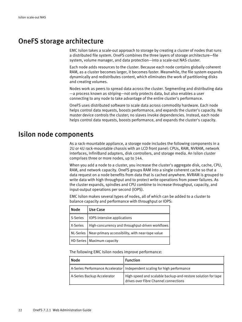
OneFS storage architectureEMC Isilon takes a scale-out approach to storage by creating a cluster of nodes that runsa distributed file system. OneFS combines the three layers of storage architecture—filesystem, volume manager, and data protection—into a scale-out NAS cluster.
Each node adds resources to the cluster. Because each node contains globally coherentRAM, as a cluster becomes larger, it becomes faster. Meanwhile, the file system expandsdynamically and redistributes content, which eliminates the work of partitioning disksand creating volumes.
Nodes work as peers to spread data across the cluster. Segmenting and distributing data—a process known as striping—not only protects data, but also enables a userconnecting to any node to take advantage of the entire cluster's performance.
OneFS uses distributed software to scale data across commodity hardware. Each nodehelps control data requests, boosts performance, and expands the cluster's capacity. Nomaster device controls the cluster; no slaves invoke dependencies. Instead, each nodehelps control data requests, boosts performance, and expands the cluster's capacity.
Isilon node componentsAs a rack-mountable appliance, a storage node includes the following components in a2U or 4U rack-mountable chassis with an LCD front panel: CPUs, RAM, NVRAM, networkinterfaces, InfiniBand adapters, disk controllers, and storage media. An Isilon clustercomprises three or more nodes, up to 144.
When you add a node to a cluster, you increase the cluster's aggregate disk, cache, CPU,RAM, and network capacity. OneFS groups RAM into a single coherent cache so that adata request on a node benefits from data that is cached anywhere. NVRAM is grouped towrite data with high throughput and to protect write operations from power failures. Asthe cluster expands, spindles and CPU combine to increase throughput, capacity, andinput-output operations per second (IOPS).
EMC Isilon makes several types of nodes, all of which can be added to a cluster tobalance capacity and performance with throughput or IOPS:
Node Use Case
S-Series IOPS-intensive applications
X-Series High-concurrency and throughput-driven workflows
NL-Series Near-primary accessibility, with near-tape value
HD-Series Maximum capacity
The following EMC Isilon nodes improve performance:
Node Function
A-Series Performance Accelerator Independent scaling for high performance
A-Series Backup Accelerator High-speed and scalable backup-and-restore solution for tapedrives over Fibre Channel connections
Isilon scale-out NAS
22 OneFS 7.2.1 Web Administration Guide
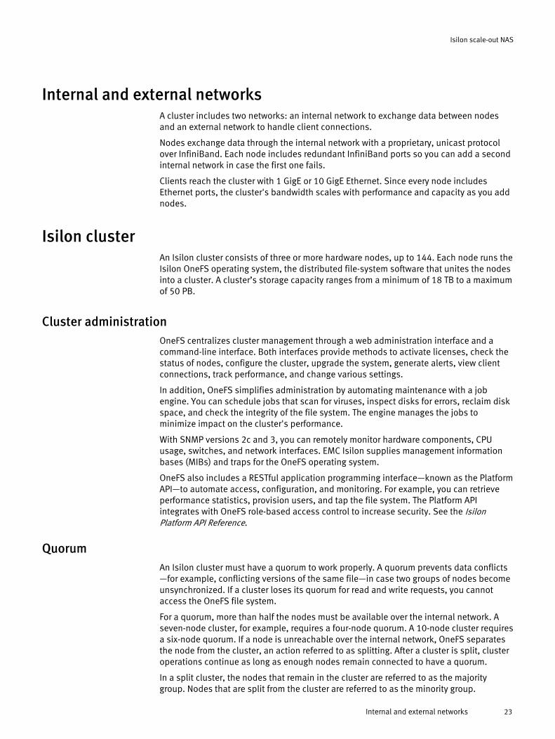
Internal and external networksA cluster includes two networks: an internal network to exchange data between nodesand an external network to handle client connections.
Nodes exchange data through the internal network with a proprietary, unicast protocolover InfiniBand. Each node includes redundant InfiniBand ports so you can add a secondinternal network in case the first one fails.
Clients reach the cluster with 1 GigE or 10 GigE Ethernet. Since every node includesEthernet ports, the cluster's bandwidth scales with performance and capacity as you addnodes.
Isilon clusterAn Isilon cluster consists of three or more hardware nodes, up to 144. Each node runs theIsilon OneFS operating system, the distributed file-system software that unites the nodesinto a cluster. A cluster’s storage capacity ranges from a minimum of 18 TB to a maximumof 50 PB.
Cluster administrationOneFS centralizes cluster management through a web administration interface and acommand-line interface. Both interfaces provide methods to activate licenses, check thestatus of nodes, configure the cluster, upgrade the system, generate alerts, view clientconnections, track performance, and change various settings.
In addition, OneFS simplifies administration by automating maintenance with a jobengine. You can schedule jobs that scan for viruses, inspect disks for errors, reclaim diskspace, and check the integrity of the file system. The engine manages the jobs tominimize impact on the cluster's performance.
With SNMP versions 2c and 3, you can remotely monitor hardware components, CPUusage, switches, and network interfaces. EMC Isilon supplies management informationbases (MIBs) and traps for the OneFS operating system.
OneFS also includes a RESTful application programming interface—known as the PlatformAPI—to automate access, configuration, and monitoring. For example, you can retrieveperformance statistics, provision users, and tap the file system. The Platform APIintegrates with OneFS role-based access control to increase security. See the IsilonPlatform API Reference.
QuorumAn Isilon cluster must have a quorum to work properly. A quorum prevents data conflicts—for example, conflicting versions of the same file—in case two groups of nodes becomeunsynchronized. If a cluster loses its quorum for read and write requests, you cannotaccess the OneFS file system.
For a quorum, more than half the nodes must be available over the internal network. Aseven-node cluster, for example, requires a four-node quorum. A 10-node cluster requiresa six-node quorum. If a node is unreachable over the internal network, OneFS separatesthe node from the cluster, an action referred to as splitting. After a cluster is split, clusteroperations continue as long as enough nodes remain connected to have a quorum.
In a split cluster, the nodes that remain in the cluster are referred to as the majoritygroup. Nodes that are split from the cluster are referred to as the minority group.
Isilon scale-out NAS
Internal and external networks 23
When split nodes can reconnect with the cluster and resynchronize with the other nodes,the nodes rejoin the cluster's majority group, an action referred to as merging.
A OneFS cluster contains two quorum properties:
l read quorum (efs.gmp.has_quorum)
l write quorum (efs.gmp.has_super_block_quorum)
By connecting to a node with SSH and running the sysctl command-line tool as root,you can view the status of both types of quorum. Here is an example for a cluster that hasa quorum for both read and write operations, as the command's output indicates with a1, for true:
sysctl efs.gmp.has_quorum efs.gmp.has_quorum: 1 sysctl efs.gmp.has_super_block_quorum efs.gmp.has_super_block_quorum: 1
The degraded states of nodes—such as smartfail, read-only, offline, and so on—affectquorum in different ways. A node in a smartfail or read-only state affects only writequorum. A node in an offline state, however, affects both read and write quorum. In acluster, the combination of nodes in different degraded states determines whether readrequests, write requests, or both work.
A cluster can lose write quorum but keep read quorum. Consider a four-node cluster inwhich nodes 1 and 2 are working normally. Node 3 is in a read-only state, and node 4 isin a smartfail state. In such a case, read requests to the cluster succeed. Write requests,however, receive an input-output error because the states of nodes 3 and 4 break thewrite quorum.
A cluster can also lose both its read and write quorum. If nodes 3 and 4 in a four-nodecluster are in an offline state, both write requests and read requests receive an input-output error, and you cannot access the file system. When OneFS can reconnect with thenodes, OneFS merges them back into the cluster. Unlike a RAID system, an Isilon nodecan rejoin the cluster without being rebuilt and reconfigured.
Splitting and mergingSplitting and merging optimize the use of nodes without your intervention.
OneFS monitors every node in a cluster. If a node is unreachable over the internalnetwork, OneFS separates the node from the cluster, an action referred to as splitting.When the cluster can reconnect to the node, OneFS adds the node back into the cluster,an action referred to as merging.
When a node is split from a cluster, it will continue to capture event information locally.You can connect to a split node with SSH and run the isi events list command toview the local event log for the node. The local event log can help you troubleshoot theconnection issue that resulted in the split. When the split node rejoins the cluster, localevents gathered during the split are deleted. You can still view events generated by asplit node in the node's event log file located at /var/log/isi_celog_events.log.
If a cluster splits during a write operation, OneFS might need to re-allocate blocks for thefile on the side with the quorum, which leads allocated blocks on the side without aquorum to become orphans. When the split nodes reconnect with the cluster, the OneFSCollect system job reclaims the orphaned blocks.
Meanwhile, as nodes split and merge with the cluster, the OneFS AutoBalance jobredistributes data evenly among the nodes in the cluster, optimizing protection andconserving space.
Isilon scale-out NAS
24 OneFS 7.2.1 Web Administration Guide
Storage poolsStorage pools segment nodes and files into logical divisions to simplify the managementand storage of data.
A storage pool comprises node pools and tiers. Node pools group equivalent nodes toprotect data and ensure reliability. Tiers combine node pools to optimize storage byneed, such as a frequently used high-speed tier or a rarely accessed archive.
The SmartPools module groups nodes and files into pools. If you do not activate aSmartPools license, the module provisions node pools and creates one file pool. If youactivate the SmartPools license, you receive more features. You can, for example, createmultiple file pools and govern them with policies. The policies move files, directories, andfile pools among node pools or tiers. You can also define how OneFS handles writeoperations when a node pool or tier is full. SmartPools reserves a virtual hot spare toreprotect data if a drive fails regardless of whether the SmartPools license is activated.
IP address poolsWithin a subnet, you can partition a cluster's external network interfaces into pools of IPaddress ranges. The pools enable you to customize your storage network to servedifferent groups of users. You can configure subnets in IPv4 or IPv6.
You can associate IP address pools with a node, a group of nodes, or NIC ports. Forexample, you can set up one subnet for storage nodes and another subnet for acceleratornodes. Similarly, you can allocate ranges of IP addresses on a subnet to different teams,such as engineering and sales. These options help you create a storage topology thatmatches the demands of your network.
In addition, network provisioning rules streamline the setup of external connections.After you configure the rules with network settings, you can apply the settings to newnodes.
As a standard feature, the OneFS SmartConnect module balances connections amongnodes by using a round-robin policy with static IP addresses and one IP address pool foreach subnet. Activating a SmartConnect Advanced license adds features, such asdefining IP address pools to support multiple DNS zones.
The OneFS operating systemA distributed operating system based on FreeBSD, OneFS presents an Isilon cluster's filesystem as a single share or export with a central point of administration.
The OneFS operating system does the following:
l Supports common data-access protocols, such as SMB and NFS.
l Connects to multiple identity management systems, such as Active Directory andLDAP.
l Authenticates users and groups.
l Controls access to directories and files.
Data-access protocolsWith the OneFS operating system, you can access data with multiple file-sharing andtransfer protocols. As a result, Microsoft Windows, UNIX, Linux, and Mac OS X clients canshare the same directories and files.
OneFS supports the following protocols.
Isilon scale-out NAS
Storage pools 25
SMB
The Server Message Block (SMB) protocol enables Windows users to access thecluster. OneFS works with SMB 1, SMB 2, and SMB 2.1, as well as SMB 3.0 forMultichannel only. With SMB 2.1, OneFS supports client opportunity locks (oplocks)and large (1 MB) MTU sizes. The default file share is /ifs.
NFS
The Network File System (NFS) protocol enables UNIX, Linux, and Mac OS X systemsto remotely mount any subdirectory, including subdirectories created by Windowsusers. OneFS works with NFS versions 3 and 4. The default export is /ifs.
HDFS
The Hadoop Distributed File System (HDFS) protocol enables a cluster to work withApache Hadoop, a framework for data-intensive distributed applications. HDFSintegration requires you to activate a separate license.
FTP
FTP allows systems with an FTP client to connect to the cluster and exchange files.
HTTP and HTTPS
HTTP and its secure variant, HTTPS, give systems browser-based access to resources.OneFS includes limited support for WebDAV.
Swift
Isilon Swift enables you to access existing file-based data stored on your EMC Isiloncluster as objects. The Swift API is implemented as a set of Representational StateTransfer (REST) web services over HTTP or secure HTTP (HTTPS). Content andmetadata can be ingested as objects and concurrently accessed through othersupported EMC Isilon protocols.
Identity management and access controlOneFS works with multiple identity management systems to authenticate users andcontrol access to files. In addition, OneFS features access zones that allow users fromdifferent directory services to access different resources based on their IP address. Role-based access control, meanwhile, segments administrative access by role.
OneFS authenticates users with the following identity management systems:
l Microsoft Active Directory (AD)
l Lightweight Directory Access Protocol (LDAP)
l Network Information Service (NIS)
l Local users and local groups
l A file provider for accounts in /etc/spwd.db and /etc/group files. With the fileprovider, you can add an authoritative third-party source of user and groupinformation.
You can manage users with different identity management systems; OneFS maps theaccounts so that Windows and UNIX identities can coexist. A Windows user accountmanaged in Active Directory, for example, is mapped to a corresponding UNIX account inNIS or LDAP.
To control access, an Isilon cluster works with both the access control lists (ACLs) ofWindows systems and the POSIX mode bits of UNIX systems. When OneFS musttransform a file's permissions from ACLs to mode bits or from mode bits to ACLs, OneFSmerges the permissions to maintain consistent security settings.
Isilon scale-out NAS
26 OneFS 7.2.1 Web Administration Guide
OneFS presents protocol-specific views of permissions so that NFS exports display modebits and SMB shares show ACLs. You can, however, manage not only mode bits but alsoACLs with standard UNIX tools, such as the chmod and chown commands. In addition,ACL policies enable you to configure how OneFS manages permissions for networks thatmix Windows and UNIX systems.
Access zones
OneFS includes an access zones feature. Access zones allow users from differentauthentication providers, such as two untrusted Active Directory domains, to accessdifferent OneFS resources based on an incoming IP address. An access zone cancontain multiple authentication providers and SMB namespaces.
RBAC for administration
OneFS includes role-based access control (RBAC) for administration. In place of aroot or administrator account, RBAC lets you manage administrative access by role.A role limits privileges to an area of administration. For example, you can createseparate administrator roles for security, auditing, storage, and backup.
Structure of the file systemOneFS presents all the nodes in a cluster as a global namespace—that is, as the defaultfile share, /ifs.
In the file system, directories are inode number links. An inode contains file metadataand an inode number, which identifies a file's location. OneFS dynamically allocatesinodes, and there is no limit on the number of inodes.
To distribute data among nodes, OneFS sends messages with a globally routable blockaddress through the cluster's internal network. The block address identifies the node andthe drive storing the block of data.
Note
It is recommended that you do not save data to the root /ifs file path but in directories
below /ifs. The design of your data storage structure should be planned carefully. A
well-designed directory optimizes cluster performance and cluster administration.
Data layoutOneFS evenly distributes data among a cluster's nodes with layout algorithms thatmaximize storage efficiency and performance. The system continuously reallocates datato conserve space.
OneFS breaks data down into smaller sections called blocks, and then the system placesthe blocks in a stripe unit. By referencing either file data or erasure codes, a stripe unithelps safeguard a file from a hardware failure. The size of a stripe unit depends on thefile size, the number of nodes, and the protection setting. After OneFS divides the datainto stripe units, OneFS allocates, or stripes, the stripe units across nodes in the cluster.
When a client connects to a node, the client's read and write operations take place onmultiple nodes. For example, when a client connects to a node and requests a file, thenode retrieves the data from multiple nodes and rebuilds the file. You can optimize howOneFS lays out data to match your dominant access pattern—concurrent, streaming, orrandom.
Isilon scale-out NAS
Structure of the file system 27
Writing filesOn a node, the input-output operations of the OneFS software stack split into twofunctional layers: A top layer, or initiator, and a bottom layer, or participant. In read andwrite operations, the initiator and the participant play different roles.
When a client writes a file to a node, the initiator on the node manages the layout of thefile on the cluster. First, the initiator divides the file into blocks of 8 KB each. Second, theinitiator places the blocks in one or more stripe units. At 128 KB, a stripe unit consists of16 blocks. Third, the initiator spreads the stripe units across the cluster until they span awidth of the cluster, creating a stripe. The width of the stripe depends on the number ofnodes and the protection setting.
After dividing a file into stripe units, the initiator writes the data first to non-volatilerandom-access memory (NVRAM) and then to disk. NVRAM retains the information whenthe power is off.
During the write transaction, NVRAM guards against failed nodes with journaling. If anode fails mid-transaction, the transaction restarts without the failed node. When thenode returns, it replays the journal from NVRAM to finish the transaction. The node alsoruns the AutoBalance job to check the file's on-disk striping. Meanwhile, uncommittedwrites waiting in the cache are protected with mirroring. As a result, OneFS eliminatesmultiple points of failure.
Reading filesIn a read operation, a node acts as a manager to gather data from the other nodes andpresent it to the requesting client.
Because an Isilon cluster's coherent cache spans all the nodes, OneFS can store differentdata in each node's RAM. By using the internal InfiniBand network, a node can retrievefile data from another node's cache faster than from its own local disk. If a read operationrequests data that is cached on any node, OneFS pulls the cached data to serve itquickly.
In addition, for files with an access pattern of concurrent or streaming, OneFS pre-fetchesin-demand data into a managing node's local cache to further improve sequential-readperformance.
Metadata layoutOneFS protects metadata by spreading it across nodes and drives.
Metadata—which includes information about where a file is stored, how it is protected,and who can access it—is stored in inodes and protected with locks in a B+ tree, astandard structure for organizing data blocks in a file system to provide instant lookups.OneFS replicates file metadata across the cluster so that there is no single point offailure.
Working together as peers, all the nodes help manage metadata access and locking. If anode detects an error in metadata, the node looks up the metadata in an alternatelocation and then corrects the error.
Isilon scale-out NAS
28 OneFS 7.2.1 Web Administration Guide
Locks and concurrencyOneFS includes a distributed lock manager that orchestrates locks on data across all thenodes in a cluster.
The lock manager grants locks for the file system, byte ranges, and protocols, includingSMB share-mode locks and NFS advisory locks. OneFS also supports SMB opportunisticlocks.
Because OneFS distributes the lock manager across all the nodes, any node can act as alock coordinator. When a thread from a node requests a lock, the lock manager's hashingalgorithm typically assigns the coordinator role to a different node. The coordinatorallocates a shared lock or an exclusive lock, depending on the type of request. A sharedlock allows users to share a file simultaneously, typically for read operations. Anexclusive lock allows only one user to access a file, typically for write operations.
StripingIn a process known as striping, OneFS segments files into units of data and thendistributes the units across nodes in a cluster. Striping protects your data and improvescluster performance.
To distribute a file, OneFS reduces it to blocks of data, arranges the blocks into stripeunits, and then allocates the stripe units to nodes over the internal network.
At the same time, OneFS distributes erasure codes that protect the file. The erasure codesencode the file's data in a distributed set of symbols, adding space-efficient redundancy.With only a part of the symbol set, OneFS can recover the original file data.
Taken together, the data and its redundancy form a protection group for a region of filedata. OneFS places the protection groups on different drives on different nodes—creatingdata stripes.
Because OneFS stripes data across nodes that work together as peers, a user connectingto any node can take advantage of the entire cluster's performance.
By default, OneFS optimizes striping for concurrent access. If your dominant accesspattern is streaming--that is, lower concurrency, higher single-stream workloads, such aswith video--you can change how OneFS lays out data to increase sequential-readperformance. To better handle streaming access, OneFS stripes data across more drives.Streaming is most effective on clusters or subpools serving large files.
Data protection overviewAn Isilon cluster is designed to serve data even when components fail. By default, OneFSprotects data with erasure codes, enabling you to retrieve files when a node or disk fails.As an alternative to erasure codes, you can protect data with two to eight mirrors.
When you create a cluster with five or more nodes, erasure codes deliver as much as 80percent efficiency. On larger clusters, erasure codes provide as much as four levels ofredundancy.
In addition to erasure codes and mirroring, OneFS includes the following features to helpprotect the integrity, availability, and confidentiality of data:
Feature Description
Antivirus OneFS can send files to servers running the Internet Content AdaptationProtocol (ICAP) to scan for viruses and other threats.
Isilon scale-out NAS
Locks and concurrency 29

Feature Description
Clones OneFS enables you to create clones that share blocks with other files to savespace.
NDMP backup andrestore
OneFS can back up data to tape and other devices through the Network DataManagement Protocol. Although OneFS supports both NDMP 3-way and 2-way backup, 2-way backup requires an Isilon Backup Accelerator node.
Protectiondomains
You can apply protection domains to files and directories to preventchanges.
The following software modules also help protect data, but they require you to activate aseparate license:
LicensedFeature
Description
SyncIQ SyncIQ replicates data on another Isilon cluster and automates failover andfailback operations between clusters. If a cluster becomes unusable, you canfail over to another Isilon cluster.
SnapshotIQ You can protect data with a snapshot—a logical copy of data stored on acluster.
SmartLock The SmartLock tool prevents users from modifying and deleting files. You cancommit files to a write-once, read-many state: The file can never be modifiedand cannot be deleted until after a set retention period. SmartLock can helpyou comply with Securities and Exchange Commission Rule 17a-4.
N+M data protectionOneFS supports N+M erasure code levels of N+1, N+2, N+3, and N+4.
In the N+M data model, N represents the number of nodes, and M represents the numberof simultaneous failures of nodes or drives that the cluster can handle without losingdata. For example, with N+2 the cluster can lose two drives on different nodes or lose twonodes.
To protect drives and nodes separately, OneFS also supports N+M:B. In the N+M:Bnotation, M is the number of disk failures, and B is the number of node failures. With N+3:1 protection, for example, the cluster can lose three drives or one node without losingdata.
The default protection level for clusters larger than 18 TB is N+2:1. The default forclusters smaller than 18 TB is N+1.
The quorum rule dictates the number of nodes required to support a protection level. Forexample, N+3 requires at least seven nodes so you can maintain a quorum if three nodesfail.
You can, however, set a protection level that is higher than the cluster can support. In afour-node cluster, for example, you can set the protection level at 5x. OneFS protects thedata at 4x until a fifth node is added, after which OneFS automatically reprotects the dataat 5x.
Isilon scale-out NAS
30 OneFS 7.2.1 Web Administration Guide

Data mirroringYou can protect on-disk data with mirroring, which copies data to multiple locations.OneFS supports two to eight mirrors. You can use mirroring instead of erasure codes, oryou can combine erasure codes with mirroring.
Mirroring, however, consumes more space than erasure codes. Mirroring data threetimes, for example, duplicates the data three times, which requires more space thanerasure codes. As a result, mirroring suits transactions that require high performance.
You can also mix erasure codes with mirroring. During a write operation, OneFS dividesdata into redundant protection groups. For files protected by erasure codes, a protectiongroup consists of data blocks and their erasure codes. For mirrored files, a protectiongroup contains all the mirrors of a set of blocks. OneFS can switch the type of protectiongroup as it writes a file to disk. By changing the protection group dynamically, OneFS cancontinue writing data despite a node failure that prevents the cluster from applyingerasure codes. After the node is restored, OneFS automatically converts the mirroredprotection groups to erasure codes.
The file system journalA journal, which records file-system changes in a battery-backed NVRAM card, recoversthe file system after failures, such as a power loss. When a node restarts, the journalreplays file transactions to restore the file system.
Virtual hot spareWhen a drive fails, OneFS uses space reserved in a subpool instead of a hot spare drive.The reserved space is known as a virtual hot spare.
In contrast to a spare drive, a virtual hot spare automatically resolves drive failures andcontinues writing data. If a drive fails, OneFS migrates data to the virtual hot spare toreprotect it. You can reserve as many as four disk drives as a virtual hot spare.
Balancing protection with storage spaceYou can set protection levels to balance protection requirements with storage space.
Higher protection levels typically consume more space than lower levels because youlose an amount of disk space to storing erasure codes. The overhead for the erasurecodes depends on the protection level, the file size, and the number of nodes in thecluster. Since OneFS stripes both data and erasure codes across nodes, the overheaddeclines as you add nodes.
VMware integrationOneFS integrates with several VMware products, including vSphere, vCenter, and ESXi.
For example, OneFS works with the VMware vSphere API for Storage Awareness (VASA) sothat you can view information about an Isilon cluster in vSphere. OneFS also works withthe VMware vSphere API for Array Integration (VAAI) to support the following features forblock storage: hardware-assisted locking, full copy, and block zeroing. VAAI for NFSrequires an ESXi plug-in.
With the Isilon for vCenter plug-in, you can backup and restore virtual machines on anIsilon cluster. With the Isilon Storage Replication Adapter, OneFS integrates with the
Isilon scale-out NAS
Data mirroring 31
VMware vCenter Site Recovery Manager to recover virtual machines that are replicatedbetween Isilon clusters.
Software modulesYou can access advanced features by activating licenses for EMC Isilon softwaremodules.
SmartLock
SmartLock protects critical data from malicious, accidental, or premature alterationor deletion to help you comply with SEC 17a-4 regulations. You can automaticallycommit data to a tamper-proof state and then retain it with a compliance clock.
SyncIQ automated failover and failback
SyncIQ replicates data on another Isilon cluster and automates failover and failbackbetween clusters. If a cluster becomes unusable, you can fail over to another Isiloncluster. Failback restores the original source data after the primary cluster becomesavailable again.
File clones
OneFS provides provisioning of full read/write copies of files, LUNs, and otherclones. OneFS also provides virtual machine linked cloning through VMware APIintegration.
SnapshotIQ
SnapshotIQ protects data with a snapshot—a logical copy of data stored on acluster. A snapshot can be restored to its top-level directory.
SmartPools
SmartPools enable you to create multiple file pools governed by file-pool policies.The policies move files and directories among node pools or tiers. You can alsodefine how OneFS handles write operations when a node pool or tier is full.
SmartConnect
If you activate a SmartConnect Advanced license, you can balance policies to evenlydistribute CPU usage, client connections, or throughput. You can also define IPaddress pools to support multiple DNS zones in a subnet. In addition, SmartConnectsupports IP failover, also known as NFS failover.
InsightIQ
The InsightIQ virtual appliance monitors and analyzes the performance of your Isiloncluster to help you optimize storage resources and forecast capacity.
Aspera for Isilon
Aspera moves large files over long distances fast. Aspera for Isilon is a cluster-awareversion of Aspera technology for non-disruptive, wide-area content delivery.
HDFS
OneFS works with the Hadoop Distributed File System protocol to help clientsrunning Apache Hadoop, a framework for data-intensive distributed applications,analyze big data.
SmartQuotas
The SmartQuotas module tracks disk usage with reports and enforces storage limitswith alerts.
Isilon scale-out NAS
32 OneFS 7.2.1 Web Administration Guide

Isilon Swift
Isilon Swift is an object storage gateway compatible with the OpenStack Swift 1.0API. Through Isilon Swift, you can access existing file-based data stored on your EMCIsilon cluster as objects. The Swift API is implemented as a set of RESTful webservices over HTTP or HTTPS. Since the Swift API is considered as a protocol, contentand metadata can be ingested as objects and concurrently accessed through othersupported EMC Isilon protocols.
Isilon scale-out NAS
Software modules 33

Isilon scale-out NAS
34 OneFS 7.2.1 Web Administration Guide
CHAPTER 3
General cluster administration
This section contains the following topics:
l General cluster administration overview................................................................36l User interfaces...................................................................................................... 36l Connecting to the cluster.......................................................................................37l Licensing...............................................................................................................38l Certificates............................................................................................................43l Cluster identity......................................................................................................45l Cluster contact information................................................................................... 46l Cluster date and time............................................................................................ 46l SMTP email settings.............................................................................................. 48l Configuring the cluster join mode..........................................................................48l File system settings...............................................................................................49l Security hardening................................................................................................ 50l Cluster monitoring.................................................................................................55l Monitoring cluster hardware..................................................................................57l Events and notifications........................................................................................64l Cluster maintenance............................................................................................. 72l Remote support.....................................................................................................81
General cluster administration 35

General cluster administration overviewYou can manage general OneFS settings and module licenses for the EMC Isilon cluster.
General cluster administration covers several areas. You can:
l manage general settings such as cluster name, date and time, and email
l monitor the cluster status and performance, including hardware components
l configure how events and notifications are handled
l perform cluster maintenance such as adding, removing, and restarting nodes
Most management tasks are accomplished through both the web administration orcommand-line interface; however, you will occasionally encounter a task that can only bemanaged by one or the other.
User interfacesOneFS provides several interfaces for managing the EMC Isilon cluster.
Interface Description Comment
OneFS webadministrationinterface
The browser-based OneFS web administrationinterface provides secure access with OneFS-supported browsers. Use this interface to viewrobust graphical monitoring displays and toperform cluster-management tasks.
The OneFS webadministration interface usesport 8080 as its default port.
OneFS command-line interface
Run OneFS isi commands in the command-
line interface to configure, monitor, andmanage the cluster. Access to the command-line interface is through a secure shell (SSH)connection to any node in the cluster.
The OneFS command-lineinterface provides anextended standard UNIXcommand set for managingthe cluster.
OneFS API The OneFS application programming interface(API) is divided into two functional areas: onearea enables cluster configuration,management, and monitoring functionality,and the other area enables operations on filesand directories on the cluster. You can sendrequests to the OneFS API through aRepresentational State Transfer (REST)interface, which is accessed through resourceURIs and standard HTTP methods.
You should have a solidunderstanding of HTTP/1.1and experience writing HTTP-based client software beforeyou implement client-basedsoftware through the OneFSAPI.
Node front panel With the exception of accelerator nodes, thefront panel of each node contains an LCDscreen with five buttons that you can use tomonitor node and cluster details.
Node status, events, clusterdetails, capacity, IP and MACaddresses, throughput, anddrive status are availablethrough the node front panel.
General cluster administration
36 OneFS 7.2.1 Web Administration Guide

Connecting to the clusterEMC Isilon cluster access is provided through the web administration interface or throughSSH. You can use a serial connection to perform cluster-administration tasks through thecommand-line interface.
You can also access the cluster through the node front panel to accomplish a subset ofcluster-management tasks. For information about connecting to the node front panel, seethe installation documentation for your node.
Log in to the web administration interfaceYou can monitor and manage your EMC Isilon cluster from the browser-based webadministration interface.
Procedure
1. Open a browser window and type the URL for your cluster in the address field,replacing <yourNodeIPaddress> with the first IP address you provided when youconfigured ext-1 in the one of the following examples:
IPv4https://<yourNodeIPaddress>:8080
IPv6https://[<yourNodeIPaddress>]:8080
The system displays a message if your security certificates have not been configured.Resolve any certificate configurations and continue to the web site.
2. Log in to OneFS by typing your OneFS credentials in the Username and Passwordfields.
After you log into the web administration interface, there is a 4-hour login timeout.
Open an SSH connection to a clusterYou can use any SSH client such as OpenSSH or PuTTY to connect to an EMC Isiloncluster.
Before you begin
You must have valid OneFS credentials to log in to a cluster after the connection is open.
Procedure
1. Open a secure shell (SSH) connection to any node in the cluster, using the IP addressof the node and port number 22.
2. Log in with your OneFS credentials.
At the OneFS command line prompt, you can use isi commands to monitor andmanage your cluster.
General cluster administration
Connecting to the cluster 37
LicensingAdvanced cluster features are available when you activate licenses for OneFS softwaremodules. Each optional OneFS software module requires you to activate a separatelicense.
For more information about the following optional software modules, contact your EMCIsilon sales representative.
l HDFS
l InsightIQ
l Isilon for vCenter
l SmartConnect Advanced
l SmartDedupe
l SmartLock
l SmartPools
l SmartQuotas
l SnapshotIQ
l SyncIQ
l Isilon Swift
General cluster administration
38 OneFS 7.2.1 Web Administration Guide

License statusThe status of a OneFS module license indicates whether the functionality provided by amodule is available on the cluster.
Licenses exist in one of the following states:
Status Description
Inactive The license has not been activated on the cluster. You cannot access the featuresprovided by the corresponding module.
Evaluation The license has been temporarily activated on the cluster. You can access thefeatures provided by the corresponding module for a limited period of time. After thelicense expires, the features become unavailable unless the license is reactivated.
Activated The license has been activated on the cluster. You can access the features providedby the corresponding module.
Expired The evaluation license has expired on the cluster. You can no longer access thefeatures provided by the corresponding module. The features will remain unavailableunless you reactivate the license.
The following table describes what functionality is available for each license dependingon the license's status:
License Inactive Evaluation/Activated
Expired
Isilon Swift Clients cannotaccess the clusterthrough Swift.
Clients can accessexisting file-baseddata stored on thecluster as objectsthrough a Swift APIclient applicationover HTTP or HTTPS.
Clients can no longer accessthe cluster through Swift.
HDFS Clients cannotaccess the clusterthrough HDFS.
You can configureHDFS settings andclients can accessthe cluster throughHDFS.
You cannot configure HDFSsettings. After the HDFSservice restarts, clients canno longer access the clusterthrough HDFS.
InsightIQ You cannot monitorthe cluster withInsightIQ.
You can monitor thecluster withInsightIQ.
InsightIQ stops monitoringthe cluster. Data previouslycollected by InsightIQ is stillavailable on the InsightIQinstance.
Isilon for vCenter You cannot back upvirtual machines thatare stored on anIsilon cluster withIsilon for vCenter.
You can back upvirtual machines thatare stored on anIsilon cluster withIsilon for vCenter.
You cannot create newbackups of virtual machinesthat are stored on an Isiloncluster.
SmartPools All files belong to thedefault file pool and
You can createmultiple file pools
You can no longer managefile pool policies, and the
General cluster administration
License status 39
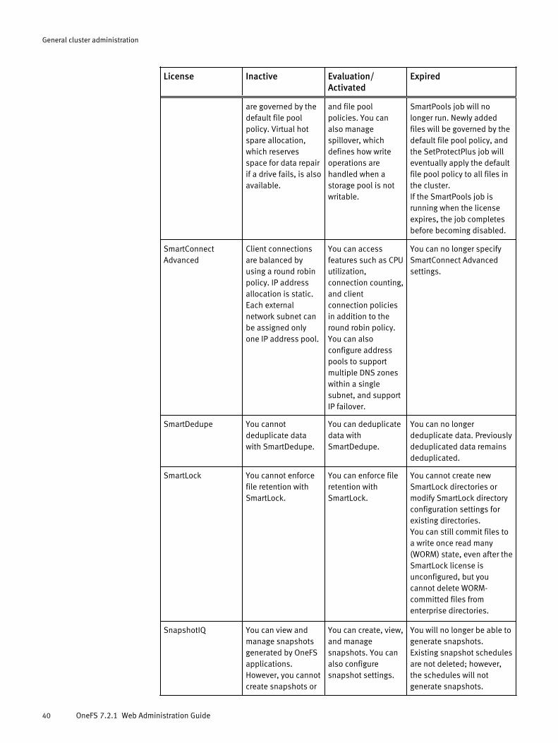
License Inactive Evaluation/Activated
Expired
are governed by thedefault file poolpolicy. Virtual hotspare allocation,which reservesspace for data repairif a drive fails, is alsoavailable.
and file poolpolicies. You canalso managespillover, whichdefines how writeoperations arehandled when astorage pool is notwritable.
SmartPools job will nolonger run. Newly addedfiles will be governed by thedefault file pool policy, andthe SetProtectPlus job willeventually apply the defaultfile pool policy to all files inthe cluster.If the SmartPools job isrunning when the licenseexpires, the job completesbefore becoming disabled.
SmartConnectAdvanced
Client connectionsare balanced byusing a round robinpolicy. IP addressallocation is static.Each externalnetwork subnet canbe assigned onlyone IP address pool.
You can accessfeatures such as CPUutilization,connection counting,and clientconnection policiesin addition to theround robin policy.You can alsoconfigure addresspools to supportmultiple DNS zoneswithin a singlesubnet, and supportIP failover.
You can no longer specifySmartConnect Advancedsettings.
SmartDedupe You cannotdeduplicate datawith SmartDedupe.
You can deduplicatedata withSmartDedupe.
You can no longerdeduplicate data. Previouslydeduplicated data remainsdeduplicated.
SmartLock You cannot enforcefile retention withSmartLock.
You can enforce fileretention withSmartLock.
You cannot create newSmartLock directories ormodify SmartLock directoryconfiguration settings forexisting directories.You can still commit files toa write once read many(WORM) state, even after theSmartLock license isunconfigured, but youcannot delete WORM-committed files fromenterprise directories.
SnapshotIQ You can view andmanage snapshotsgenerated by OneFSapplications.However, you cannotcreate snapshots or
You can create, view,and managesnapshots. You canalso configuresnapshot settings.
You will no longer be able togenerate snapshots.Existing snapshot schedulesare not deleted; however,the schedules will notgenerate snapshots.
General cluster administration
40 OneFS 7.2.1 Web Administration Guide
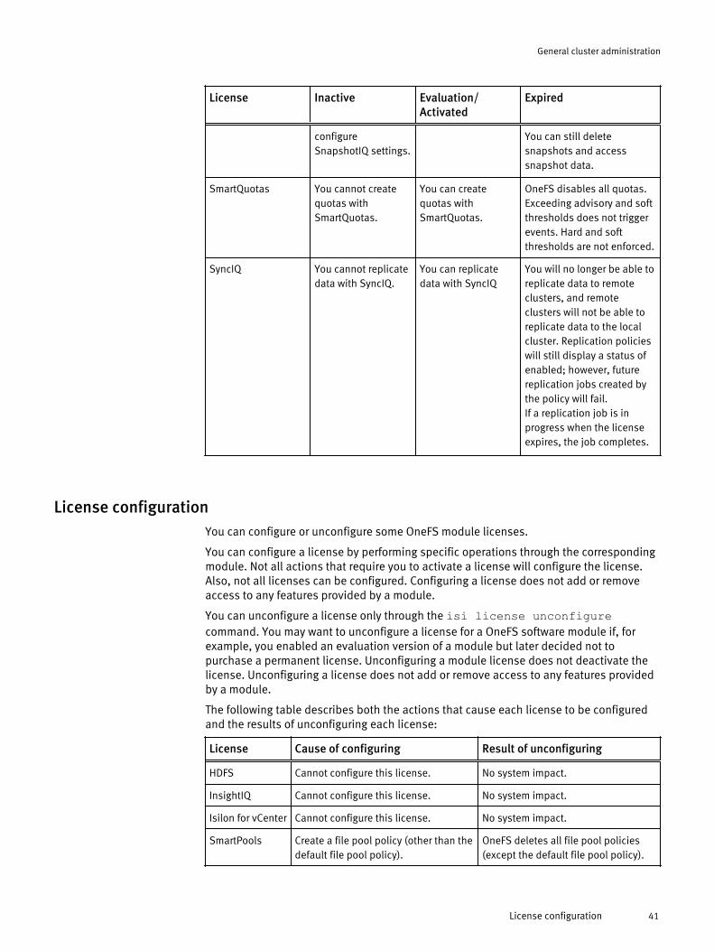
License Inactive Evaluation/Activated
Expired
configureSnapshotIQ settings.
You can still deletesnapshots and accesssnapshot data.
SmartQuotas You cannot createquotas withSmartQuotas.
You can createquotas withSmartQuotas.
OneFS disables all quotas.Exceeding advisory and softthresholds does not triggerevents. Hard and softthresholds are not enforced.
SyncIQ You cannot replicatedata with SyncIQ.
You can replicatedata with SyncIQ
You will no longer be able toreplicate data to remoteclusters, and remoteclusters will not be able toreplicate data to the localcluster. Replication policieswill still display a status ofenabled; however, futurereplication jobs created bythe policy will fail.If a replication job is inprogress when the licenseexpires, the job completes.
License configurationYou can configure or unconfigure some OneFS module licenses.
You can configure a license by performing specific operations through the correspondingmodule. Not all actions that require you to activate a license will configure the license.Also, not all licenses can be configured. Configuring a license does not add or removeaccess to any features provided by a module.
You can unconfigure a license only through the isi license unconfigurecommand. You may want to unconfigure a license for a OneFS software module if, forexample, you enabled an evaluation version of a module but later decided not topurchase a permanent license. Unconfiguring a module license does not deactivate thelicense. Unconfiguring a license does not add or remove access to any features providedby a module.
The following table describes both the actions that cause each license to be configuredand the results of unconfiguring each license:
License Cause of configuring Result of unconfiguring
HDFS Cannot configure this license. No system impact.
InsightIQ Cannot configure this license. No system impact.
Isilon for vCenter Cannot configure this license. No system impact.
SmartPools Create a file pool policy (other than thedefault file pool policy).
OneFS deletes all file pool policies(except the default file pool policy).
General cluster administration
License configuration 41
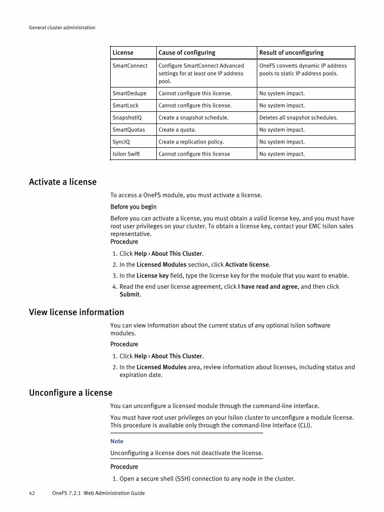
License Cause of configuring Result of unconfiguring
SmartConnect Configure SmartConnect Advancedsettings for at least one IP addresspool.
OneFS converts dynamic IP addresspools to static IP address pools.
SmartDedupe Cannot configure this license. No system impact.
SmartLock Cannot configure this license. No system impact.
SnapshotIQ Create a snapshot schedule. Deletes all snapshot schedules.
SmartQuotas Create a quota. No system impact.
SyncIQ Create a replication policy. No system impact.
Isilon Swift Cannot configure this license No system impact.
Activate a licenseTo access a OneFS module, you must activate a license.
Before you begin
Before you can activate a license, you must obtain a valid license key, and you must haveroot user privileges on your cluster. To obtain a license key, contact your EMC Isilon salesrepresentative.Procedure
1. Click Help > About This Cluster.
2. In the Licensed Modules section, click Activate license.
3. In the License key field, type the license key for the module that you want to enable.
4. Read the end user license agreement, click I have read and agree, and then clickSubmit.
View license informationYou can view information about the current status of any optional Isilon softwaremodules.
Procedure
1. Click Help > About This Cluster.
2. In the Licensed Modules area, review information about licenses, including status andexpiration date.
Unconfigure a licenseYou can unconfigure a licensed module through the command-line interface.
You must have root user privileges on your Isilon cluster to unconfigure a module license.This procedure is available only through the command-line interface (CLI).
Note
Unconfiguring a license does not deactivate the license.
Procedure
1. Open a secure shell (SSH) connection to any node in the cluster.
General cluster administration
42 OneFS 7.2.1 Web Administration Guide
You must log in as root.
2. Run the isi license unconfigure command.
The following command unconfigures the license for SmartConnect:
isi license unconfigure -m smartconnect
If you do not know the module name, run the isi license command for a list ofOneFS modules and their status.
OnesFS returns a confirmation message similar to the following text: TheSmartConnect module has been unconfigured. The license isunconfigured, and any processes enabled for the module are disabled.
CertificatesYou can renew the Secure Sockets Layer (SSL) certificate for the Isilon web administrationinterface or replace it with a third-party SSL certificate.
All Platform API communication, which includes communication through the webadministration interface, is over SSL. You can replace or renew the self-signed certificatewith a certificate that you generate. To replace or renew an SSL certificate, you must belogged in as root.
Replace or renew the SSL certificateYou can replace or renew the Secure Sockets Layer (SSL) certificate, which is used toaccess the EMC Isilon cluster through a browser.
Before you begin
When you renew or replace a self-signed SSL certificate, you must provide information foryour organization in the format that is described in the Self-signed SSL certificate dataexample.
The following folders are the default locations for the server.crt and server.keyfiles in OneFS 6.0 and higher.
l SSL certificate: /usr/local/apache2/conf/ssl.crt/server.crtl SSL certificate key: /usr/local/apache2/conf/ssl.key/server.keyProcedure
1. Establish an SSH connection to any node in the cluster.
2. At the command prompt, run the following command to create the appropriatedirectory.
mkdir /ifs/local/
3. At the command prompt, run the following command to change to the directory.
cd /ifs/local/
4. Choose the type of certificate you want to install.
General cluster administration
Certificates 43
Option Description
Third-party(public orprivate) CA-issuedcertificate
a. At the command prompt, run the following command togenerate a new Certificate Signing Request (CSR) in addition toa new key, where <common_name> is the host name, such asisilon.example.com:
openssl req -new -nodes -newkey rsa:1024 -keyout <common name>.key \ -out <common-name>.csr
b. Send the contents of the <common_name>.csr file from thecluster to your Certificate Authority (CA) for signing. When youreceive the signed certificate (now a .crt file) from the CA,copy the certificate to /ifs/local/<common-name>.crt.
Self-signedcertificatebased on theexisting (stock)ssl.key
a. At the command prompt, run the following command to create atwo-year certificate. Increase or decrease the value for -daysto generate a certificate with a different expiration date.
cp /usr/local/apache2/conf/ssl.key/server.key ./openssl req -new \/ -days 730 -nodes -x509 -key server.key -out server.crt
A renewal certificate is created, based on the existing (stock) ssl.key file.
5. (Optional) At the command prompt, run the following command to verify the attributesin an SSL certificate.
openssl x509 -text -noout -in <common-name>.crt
6. Run the following commands to install the certificate and key:
isi services -a isi_webui disablechmod 640 <common name>.keyisi_for_array -s 'cp /ifs/local/<common-name>.key /usr/local/apache2/conf/ssl.key/server.key'isi_for_array -s 'cp /ifs/local/<common-name>.crt /usr/local/apache2/conf/ssl.crt/server.crt'isi services -a isi_webui enable
7. Run the following command to remove the files in /ifs/local.
rm /ifs/local/*
Verify an SSL certificate updateYou can verify the details stored in a Secure Sockets Layer (SSL) certificate.
Procedure
1. Open a web browser window.
2. Browse to https://<common name>:8080, where <common name> is the hostname for the EMC Isilon web administration interface, such as isilon.example.com.
3. In the security details for the web page, verify that the subject line and other detailsthat you provided are correct.
General cluster administration
44 OneFS 7.2.1 Web Administration Guide
Note
The steps to view security details vary by browser. For example, in some browsers, youcan click the padlock icon in the address bar to view the security details for the webpage. Follow the steps that are specific to your browser.
Self-signed SSL certificate data exampleSelf-signed SSL certificate renewal or replacement requires you to provide data such asyour fully qualified domain name and a contact email address.
When you renew or replace a self-signed SSL certificate, you are asked to provide data inthe format shown in the following example. Some fields in the certificate file contain adefault value. If you type '.', the field is left blank when the certificate is generated.
l Country Name (2 letter code) [XX]:USl State or Province Name (full name) [Some-State]:Washingtonl Locality Name (for example, city) [default city]:Seattlel Organization Name (for example, company) [Internet Widgits Pty Ltd]:Isilonl Organizational Unit Name (for example, section) []:Supportl Common Name (for example, server FQDN or server name) []:isilon.example.coml Email Address []:[email protected] addition, you should add the following attributes to be sent with your certificaterequest:
l Challenge password []:Isilon1l Optional company name []:
Cluster identityYou can specify identity attributes for the EMC Isilon cluster.
Cluster name
The cluster name appears on the login page, and it makes the cluster and its nodesmore easily recognizable on your network. Each node in the cluster is identified bythe cluster name plus the node number. For example, the first node in a clusternamed Images may be named Images-1.
Cluster description
The cluster description appears below the cluster name on the login page. Thecluster description is useful if your environment has multiple clusters.
Login message
The login message appears as a separate box on the login page. The login messagecan convey cluster information, login instructions, or warnings that a user shouldknow before logging into the cluster.
General cluster administration
Self-signed SSL certificate data example 45
Set the cluster nameYou can specify a name, description, and login message to your EMC Isilon cluster.
Cluster names must begin with a letter and can contain only numbers, letters, andhyphens. If the cluster is joined to an Active Directory domain, the cluster name must be11 characters or fewer.
Procedure
1. Click Cluster Management > General Settings > Cluster Identity.
2. (Optional) In the Cluster Name and Description area, type a name for the cluster in theCluster Name field and type a description in the Cluster Description field.
3. (Optional) In the Login Message area, type a title in the Message Title field and amessage in the Message Body field.
4. Click Submit.
After you finish
You must add the cluster name to your DNS servers.
Cluster contact informationIsilon Technical Support personnel and event notification recipients will communicatewith the specified contacts.
You can specify the following contact information for your EMC Isilon cluster:
l Company name and location
l Primary and secondary contact names
l Phone number and email address for each contact
Specify contact informationYou can specify contact information so that Isilon Technical Support personnel and eventnotification recipients can contact you.
Procedure
1. Click Cluster Management > General Settings > Cluster Identity.
2. In the Contact Information area, type the name and contact information in the fieldsfor those details.
3. Click Submit.
To modify this information, you can access the aforementioned screen, or you can goto the Contact Information area of Dashboard > Events > Notification Settings.
Cluster date and timeThe Network Time Protocol (NTP) service is configurable manually, so you can ensure thatall nodes in a cluster are synchronized to the same time source.
The NTP method automatically synchronizes cluster date and time settings through anNTP server. Alternatively, you can set the date and time reported by the cluster bymanually configuring the service.
Windows domains provide a mechanism to synchronize members of the domain to amaster clock running on the domain controllers, so OneFS adjusts the cluster time to that
General cluster administration
46 OneFS 7.2.1 Web Administration Guide
of Active Directory with a service. If there are no external NTP servers configured, OneFSuses the Windows domain controller as the NTP time server. When the cluster anddomain time become out of sync by more than 4 minutes, OneFS generates an eventnotification.
Note
If the cluster and Active Directory become out of sync by more than 5 minutes,authentication will not work.
Set the cluster date and timeYou can set the date, time, and time zone that is used by the EMC Isilon cluster.
Procedure
1. Click Cluster Management > General Settings > Date & Time.
The Date and Time page displays a list of each node's IP address and the date andtime settings for each node.
2. From the Date and time lists, select the month, date, year, hour, and minute settings.
3. From the Time zone list, select a value.
If the time zone that you want is not in the list, select Advanced from the Time zonelist, and then select the time zone from the Advanced time zone list.
4. Click Submit.
Specify an NTP time serverYou can specify one or more Network Time Protocol (NTP) servers to synchronize thesystem time on the EMC Isilon cluster. The cluster periodically contacts the NTP serversand sets the date and time based on the information that it receives.
Procedure
1. Click Cluster Management > General Settings > NTP.
2. (Optional) Add a server.
a. In the Server IP or hostname field, type the IPv4 or IPv6 address or host name ofthe NTP server, click Add, and then click Submit.
b. (Optional) To enable NTP authentication with a keyfile, type the path and file namein the Keyfile field, and then click Submit.
3. (Optional) Delete a server.
a. Select the check box next to the server name in the Server list for each server thatyou want to delete.
b. Click Delete.
c. Click Submit.
General cluster administration
Set the cluster date and time 47
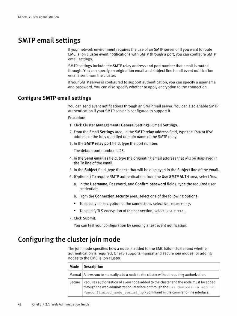
SMTP email settingsIf your network environment requires the use of an SMTP server or if you want to routeEMC Isilon cluster event notifications with SMTP through a port, you can configure SMTPemail settings.
SMTP settings include the SMTP relay address and port number that email is routedthrough. You can specify an origination email and subject line for all event notificationemails sent from the cluster.
If your SMTP server is configured to support authentication, you can specify a usernameand password. You can also specify whether to apply encryption to the connection.
Configure SMTP email settingsYou can send event notifications through an SMTP mail server. You can also enable SMTPauthentication if your SMTP server is configured to support it.
Procedure
1. Click Cluster Management > General Settings > Email Settings.
2. From the Email Settings area, in the SMTP relay address field, type the IPv4 or IPv6address or the fully qualified domain name of the SMTP relay.
3. In the SMTP relay port field, type the port number.
The default port number is 25.
4. In the Send email as field, type the originating email address that will be displayed inthe To line of the email.
5. In the Subject field, type the text that will be displayed in the Subject line of the email.
6. (Optional) To require SMTP authentication, from the Use SMTP AUTH area, select Yes.
a. In the Username, Password, and Confirm password fields, type the required usercredentials.
b. From the Connection security area, select one of the following options:
l To specify no encryption of the connection, select No security.
l To specify TLS encryption of the connection, select STARTTLS.
7. Click Submit.
You can test your configuration by sending a test event notification.
Configuring the cluster join modeThe join mode specifies how a node is added to the EMC Isilon cluster and whetherauthentication is required. OneFS supports manual and secure join modes for addingnodes to the EMC Isilon cluster.
Mode Description
Manual Allows you to manually add a node to the cluster without requiring authorization.
Secure Requires authorization of every node added to the cluster and the node must be addedthrough the web administration interface or through the isi devices -a add -d<unconfigured_node_serial_no> command in the command-line interface.
General cluster administration
48 OneFS 7.2.1 Web Administration Guide
Mode Description
Note
If you specify a secure join mode, you cannot join a node to the cluster through serialconsole wizard option [2] Join an existing cluster.
Specify the cluster join modeYou can specify a join mode that determines how nodes are added to the EMC Isiloncluster.
Procedure
1. Click Cluster Management > General Settings > Join Mode.
2. In the Settings area, select the mode that will determine how nodes can be added tothe cluster.
l Manual— joins can be manually initiated.
l Secure—joins can be initiated only by the cluster and require authentication.
3. Click Submit.
File system settingsYou can configure global file system settings on an EMC Isilon cluster pertaining toaccess time tracking and character encoding.
You can enable or disable access time tracking, which monitors the time of access oneach file. If necessary, you can also change the default character encoding on the cluster.
Enable or disable access time trackingYou can enable access time tracking to support features that require it.
By default, the EMC Isilon cluster does not track the timestamp when files are accessed.You can enable this feature to support OneFS features that use it. For example, access-time tracking must be enabled to configure SyncIQ policy criteria that match files basedon when they were last accessed.
Note
Enabling access-time tracking may affect cluster performance.
Procedure
1. Click File System Management > File System Settings > Access Time Tracking.
2. In the Access Time Tracking area, select a configuration option.
l To enable access time tracking, click Enabled, and then specify in the Precisionfields how often to update the last-accessed time by typing a numeric value and byselecting a unit of measure, such as Seconds, Minutes, Hours, Days, Weeks,Months, or Years.
For example, if you configure a Precision setting of 1 day, the cluster updates thelast-accessed time once each day, even if some files were accessed more oftenthan once during the day.
General cluster administration
Specify the cluster join mode 49
l To disable access-time tracking, click Disabled.
3. Click Submit.
Specify the cluster character encodingYou can modify the character encoding set for the EMC Isilon cluster after installation.
Only OneFS-supported character sets are available for selection. UTF-8 is the defaultcharacter set for OneFS nodes.
Note
If the cluster character encoding is not set to UTF-8, SMB share names are case-sensitive.
You must restart the cluster to apply character encoding changes.
CAUTION
Character encoding is typically established during installation of the cluster. Modifyingthe character encoding setting after installation may render files unreadable if doneincorrectly. Modify settings only if necessary after consultation with Isilon TechnicalSupport.
Procedure
1. Click File System Management > File System Settings > Character Encoding.
2. (Optional) From the Character encoding list, select the character-encoding set thatyou want to use.
3. Click Submit, and then click Yes to acknowledge that the encoding change becomeseffective after the cluster is restarted.
4. Restart the cluster.
Results
After the cluster restarts, the web administration interface reflects your change.
Security hardeningSecurity hardening is the process of configuring your system to reduce or eliminate asmany security risks as possible. You can apply a hardening policy that secures theconfiguration of OneFS, according to policy guidelines.
Security hardening on OneFS is carried out by a hardening engine that reads a hardeningprofile and applies the profile guidelines. During this process, the hardening engineidentifies configuration issues that will prevent hardening on the nodes. For example, thehardening engine might find that the file permissions set for a particular directory are notset to the expected value, or that the required directories are missing. When an issue isfound, you can choose to allow the hardening engine to resolve the issue or to deferresolution and fix the issue manually.
Note
At this time, OneFS supports only Defense Information Systems Agency (DISA) SecurityTechnology Security Guide (STIG) hardening. No other security profiles are available.
OneFS enables you to revert a security hardening policy if the hardening configuration isnot right for your system. Reverting a policy returns OneFS to the configuration achievedby resolving issues, if any, prior to hardening.
General cluster administration
50 OneFS 7.2.1 Web Administration Guide

OneFS also enables you to apply successive hardening. If a security hardening policy hasalready been applied to the system, you can apply a new policy with a new profile or withthe same profile.
You must have an active security hardening license and be logged in to the cluster as theroot user to apply hardening to OneFS. To obtain a license, contact your EMC Isilon salesrepresentative.
STIG hardening profileThe STIG hardening profile contains configuration requirements set by the Department ofDefense.
To meet federal Approved Products List (APL) requirements, the configuration of OneFSmust comply with several Security Technology Implementation Guides (STIG) that containhardening configuration requirements. STIGs are maintained by the Defense InformationSystems Agency (DISA), which produces a STIG for several computing technologiesreferred to as assessment areas. The STIG hardening profile contains the requirementsfor all of the assessment areas that are applicable to OneFS.
After you apply the STIG hardening profile, the configuration of OneFS is modified to meetthe STIG requirements. The following modifications are examples of the many systemchanges:
l After you log in through SSH or the web interface, the system will display a messagethat you are accessing a U.S. Government Information System and will display theterms and conditions of using the system.
l On each node, SSH and the web interface will listen only on the node's external IPaddress.
l Password complexity requirements for local user accounts will increase. Passwordsmust be at least 14 characters and contain at least one of each of the followingcharacter types: numeric, uppercase, lowercase, symbol.
l Root SSH will be disabled. To log in after hardening is applied, you can log in as rootonly through the web interface or through a serial console session.
STIG profile assessment areasThe STIG hardening profile contains configuration requirements for several aspects of thesystem, which are referred to as areas of assessment.
The following table displays each area of assessment and the associated SecurityTechnology Implementation Guide (STIG) that is enforced by the hardening profile:
Area of assessment STIG
Operating system UNIX Manual SRG - Version 1, Release 3UNIX Policy Manual SRG - Version 1, Release 2
Apache Web server Apache 2.2 STIG UNIX - Version 1, Release 4
Web server Web Server SRG - Version 1, Release 1Web Policy Manual STIG - Version 1, Release 1
Application security anddevelopment
Application Security and Development STIG - Version 3, Release 8
Application server Application Server SRG - Version 1, Release 1
Network Network Devices STIG - Version 8, Release 17
General cluster administration
STIG hardening profile 51
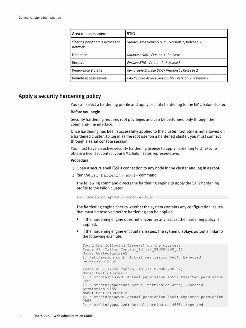
Area of assessment STIG
Sharing peripherals across thenetwork
Storage Area Network STIG - Version 2, Release 2
Database Database SRG - Version 1, Release 1
Enclave Enclave STIG - Version 4, Release 5
Removable storage Removable Storage STIG - Version 1, Release 2
Remote access server RAS Remote Access Server STIG - Version 2, Release 7
Apply a security hardening policyYou can select a hardening profile and apply security hardening to the EMC Isilon cluster.
Before you begin
Security hardening requires root privileges and can be performed only through thecommand-line interface.
Once hardening has been successfully applied to the cluster, root SSH is not allowed ona hardened cluster. To log in as the root user on a hardened cluster, you must connectthrough a serial console session.
You must have an active security hardening license to apply hardening to OneFS. Toobtain a license, contact your EMC Isilon sales representative.
Procedure
1. Open a secure shell (SSH) connection to any node in the cluster and log in as root.
2. Run the isi hardening apply command.
The following command directs the hardening engine to apply the STIG hardeningprofile to the Isilon cluster.
isi hardening apply --profile=STIG
The hardening engine checks whether the system contains any configuration issuesthat must be resolved before hardening can be applied.
l If the hardening engine does not encounter any issues, the hardening policy isapplied.
l If the hardening engine encounters issues, the system displays output similar tothe following example:
Found the following Issue(s) on the cluster:Issue #1 (Isilon Control_id:isi_GEN001200_01)Node: test-cluster-21: /etc/syslog.conf: Actual permission 0664; Expected permission 0654
Issue #2 (Isilon Control_id:isi_GEN001200_02)Node: test-cluster-31: /usr/bin/passwd: Actual permission 4555; Expected permission 05552: /usr/bin/yppasswd: Actual permission 4555; Expected permission 0555Node: test-cluster-21: /usr/bin/passwd: Actual permission 4555; Expected permission 05552: /usr/bin/yppasswd: Actual permission 4555; Expected
General cluster administration
52 OneFS 7.2.1 Web Administration Guide
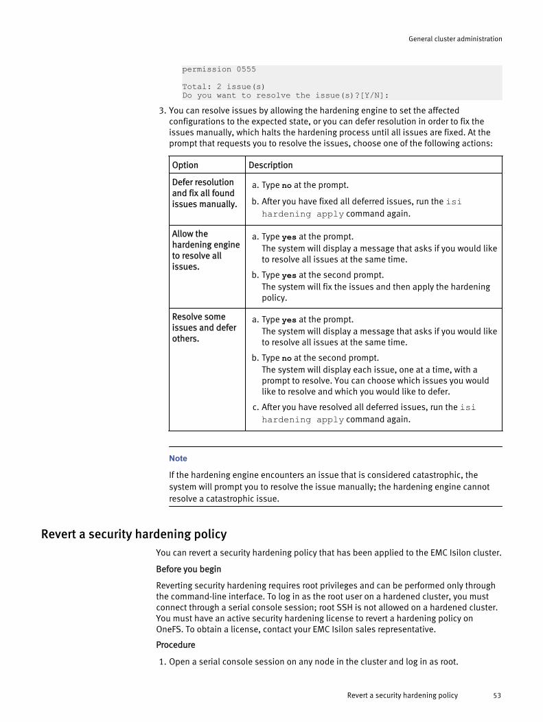
permission 0555
Total: 2 issue(s)Do you want to resolve the issue(s)?[Y/N]:
3. You can resolve issues by allowing the hardening engine to set the affectedconfigurations to the expected state, or you can defer resolution in order to fix theissues manually, which halts the hardening process until all issues are fixed. At theprompt that requests you to resolve the issues, choose one of the following actions:
Option Description
Defer resolutionand fix all foundissues manually.
a. Type no at the prompt.
b. After you have fixed all deferred issues, run the isihardening apply command again.
Allow thehardening engineto resolve allissues.
a. Type yes at the prompt.The system will display a message that asks if you would liketo resolve all issues at the same time.
b. Type yes at the second prompt.The system will fix the issues and then apply the hardeningpolicy.
Resolve someissues and deferothers.
a. Type yes at the prompt.The system will display a message that asks if you would liketo resolve all issues at the same time.
b. Type no at the second prompt.The system will display each issue, one at a time, with aprompt to resolve. You can choose which issues you wouldlike to resolve and which you would like to defer.
c. After you have resolved all deferred issues, run the isihardening apply command again.
Note
If the hardening engine encounters an issue that is considered catastrophic, thesystem will prompt you to resolve the issue manually; the hardening engine cannotresolve a catastrophic issue.
Revert a security hardening policyYou can revert a security hardening policy that has been applied to the EMC Isilon cluster.
Before you begin
Reverting security hardening requires root privileges and can be performed only throughthe command-line interface. To log in as the root user on a hardened cluster, you mustconnect through a serial console session; root SSH is not allowed on a hardened cluster.You must have an active security hardening license to revert a hardening policy onOneFS. To obtain a license, contact your EMC Isilon sales representative.
Procedure
1. Open a serial console session on any node in the cluster and log in as root.
General cluster administration
Revert a security hardening policy 53
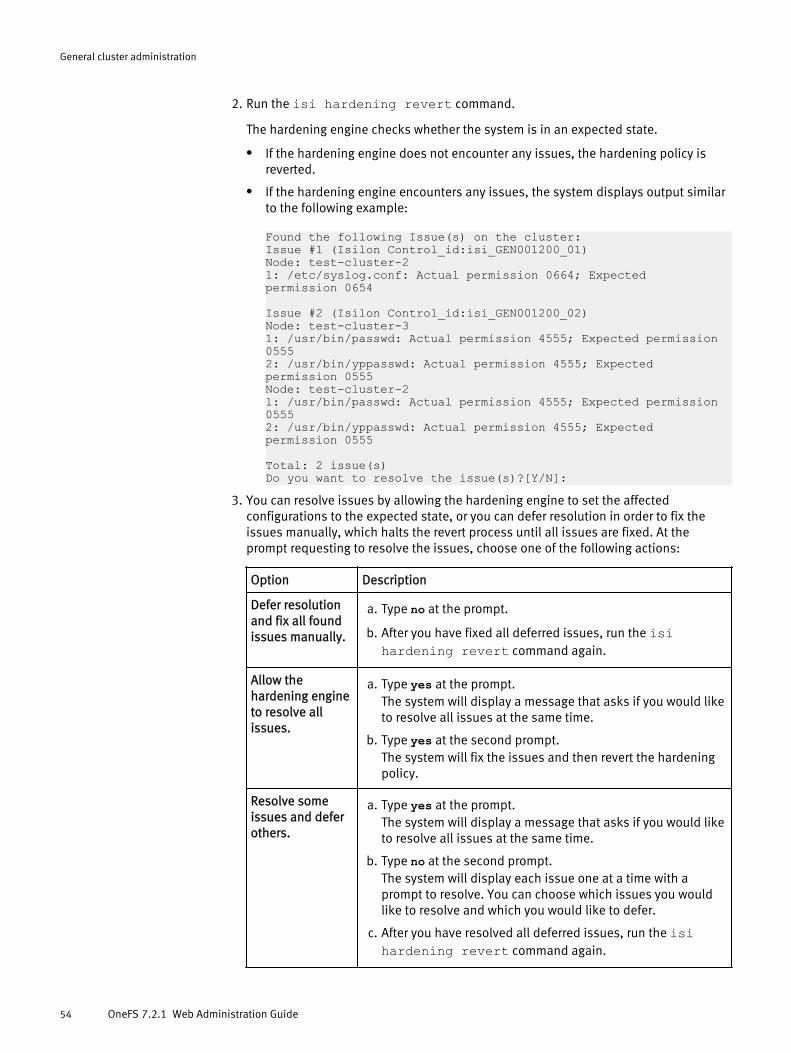
2. Run the isi hardening revert command.
The hardening engine checks whether the system is in an expected state.
l If the hardening engine does not encounter any issues, the hardening policy isreverted.
l If the hardening engine encounters any issues, the system displays output similarto the following example:
Found the following Issue(s) on the cluster:Issue #1 (Isilon Control_id:isi_GEN001200_01)Node: test-cluster-21: /etc/syslog.conf: Actual permission 0664; Expected permission 0654
Issue #2 (Isilon Control_id:isi_GEN001200_02)Node: test-cluster-31: /usr/bin/passwd: Actual permission 4555; Expected permission 05552: /usr/bin/yppasswd: Actual permission 4555; Expected permission 0555Node: test-cluster-21: /usr/bin/passwd: Actual permission 4555; Expected permission 05552: /usr/bin/yppasswd: Actual permission 4555; Expected permission 0555
Total: 2 issue(s)Do you want to resolve the issue(s)?[Y/N]:
3. You can resolve issues by allowing the hardening engine to set the affectedconfigurations to the expected state, or you can defer resolution in order to fix theissues manually, which halts the revert process until all issues are fixed. At theprompt requesting to resolve the issues, choose one of the following actions:
Option Description
Defer resolutionand fix all foundissues manually.
a. Type no at the prompt.
b. After you have fixed all deferred issues, run the isihardening revert command again.
Allow thehardening engineto resolve allissues.
a. Type yes at the prompt.The system will display a message that asks if you would liketo resolve all issues at the same time.
b. Type yes at the second prompt.The system will fix the issues and then revert the hardeningpolicy.
Resolve someissues and deferothers.
a. Type yes at the prompt.The system will display a message that asks if you would liketo resolve all issues at the same time.
b. Type no at the second prompt.The system will display each issue one at a time with aprompt to resolve. You can choose which issues you wouldlike to resolve and which you would like to defer.
c. After you have resolved all deferred issues, run the isihardening revert command again.
General cluster administration
54 OneFS 7.2.1 Web Administration Guide
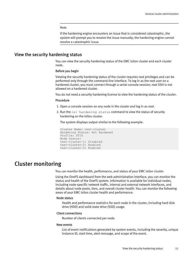
Note
If the hardening engine encounters an issue that is considered catastrophic, thesystem will prompt you to resolve the issue manually; the hardening engine cannotresolve a catastrophic issue.
View the security hardening statusYou can view the security hardening status of the EMC Isilon cluster and each clusternode.
Before you begin
Viewing the security hardening status of the cluster requires root privileges and can beperformed only through the command-line interface. To log in as the root user on ahardened cluster, you must connect through a serial console session; root SSH is notallowed on a hardened cluster.
You do not need a security hardening license to view the hardening status of the cluster.
Procedure
1. Open a console session on any node in the cluster and log in as root.
2. Run the isi hardening status command to view the status of securityhardening on the Isilon cluster.
The system displays output similar to the following example:
Cluster Name: test-clusterHardening Status: Not HardenedProfile: STIGNode status:test-cluster-1: Disabledtest-cluster-2: Enabledtest-cluster-3: Enabled
Cluster monitoringYou can monitor the health, performance, and status of your EMC Isilon cluster.
Using the OneFS dashboard from the web administration interface, you can monitor thestatus and health of the OneFS system. Information is available for individual nodes,including node-specific network traffic, internal and external network interfaces, anddetails about node pools, tiers, and overall cluster health. You can monitor the followingareas of your EMC Isilon cluster health and performance:
Node status
Health and performance statistics for each node in the cluster, including hard diskdrive (HDD) and solid-state drive (SSD) usage.
Client connections
Number of clients connected per node.
New events
List of event notifications generated by system events, including the severity, uniqueinstance ID, start time, alert message, and scope of the event.
General cluster administration
View the security hardening status 55
Cluster size
Current view: Used and available HDD and SSD space and space reserved for thevirtual hot spare (VHS).
Historical view: Total used space and cluster size for a one-year period.
Cluster throughput (file system)
Current view: Average inbound and outbound traffic volume passing through thenodes in the cluster for the past hour.
Historical view: Average inbound and outbound traffic volume passing through thenodes in the cluster for the past two weeks.
CPU usage
Current view: Average system, user, and total percentages of CPU usage for the pasthour.
Historical view: CPU usage for the past two weeks.
Monitor the clusterYou can monitor the health and performance of an EMC Isilon cluster with charts andtables that show the status and performance of nodes, client connections, events, clustersize, cluster throughput, and CPU usage.
Procedure
1. Click Dashboard > Cluster Overview > Cluster Status.
2. (Optional) View cluster details.
l Status: To view details about a node, click the ID number of the node.
l Client connection summary: To view a list of current connections, click Dashboard >Cluster Overview > Client Connections Status.
l New events: To view more information about an event, click View details in theActions column.
l Cluster size: To switch between current and historical views, click Historical orCurrent near the Monitoring section heading. In historical view, click Used orCluster size to change the display.
l Cluster throughput (file system): To switch between current and historical views,click Historical or Current next to the Monitoring section heading. To viewthroughput statistics for a specific period within the past two weeks, clickDashboard > Cluster Overview > Throughput Distribution.
Note
You can hide or show inbound or outbound throughput by clicking Inbound orOutbound in the chart legend. To view maximum throughput, next to Show, selectMaximum.
l CPU usage: To switch between current and historical views, click Historical orCurrent near the Monitoring section heading.
Note
You can hide or show a plot by clicking System, User, or Total in the chart legend.To view maximum usage, next to Show, select Maximum.
General cluster administration
56 OneFS 7.2.1 Web Administration Guide
View node statusYou can view the current and historical status of a node.
Procedure
1. Click Dashboard > Cluster Overview > Cluster Status.
2. (Optional) In the Status area, click the ID number for the node that you want to viewstatus for.
3. View node details.
l Status: To view networks settings for a node interface or subnet or pool, click thelink in the Status area.
l Client connections: To view current clients connected to this node, review the listin this area.
l Chassis and drive status: To view the state of drives in this node, review this area.To view details about a drive, click the name link of the drive; for example, Bay1.
l Node size: To switch between current and historical views, click Historical orCurrent next to the Monitoring area heading. In historical view, click Used orCluster size to change the display accordingly.
l Node throughput (file system): To switch between current and historical views,click Historical or Current next to the Monitoring area heading. To view throughputstatistics for a period within the past two weeks, click Dashboard > ClusterOverview > Throughput Distribution.
Note
You can hide or show inbound or outbound throughput by clicking Inbound orOutbound in the chart legend. To view maximum throughput, next to Show, selectMaximum.
l CPU usage: To switch between current and historical views, click Historical orCurrent next to the Monitoring area heading.
Note
You can hide or show a plot by clicking System, User, or Total in the chart legend.To view maximum usage, next to Show, select Maximum.
Monitoring cluster hardwareYou can manually check the status of hardware on the EMC Isilon cluster as well asenable SNMP to remotely monitor components.
View node hardware statusYou can view the hardware status of a node.
Procedure
1. Click Dashboard > Cluster Overview > Cluster Status.
2. (Optional) In the Status area, click the ID number for a node.
3. In the Chassis and drive status area, click Platform.
General cluster administration
View node status 57
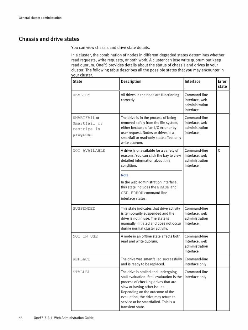
Chassis and drive statesYou can view chassis and drive state details.
In a cluster, the combination of nodes in different degraded states determines whetherread requests, write requests, or both work. A cluster can lose write quorum but keepread quorum. OneFS provides details about the status of chassis and drives in yourcluster. The following table describes all the possible states that you may encounter inyour cluster.
State Description Interface Errorstate
HEALTHY All drives in the node are functioningcorrectly.
Command-lineinterface, webadministrationinterface
SMARTFAIL or
Smartfail orrestripe inprogress
The drive is in the process of beingremoved safely from the file system,either because of an I/O error or byuser request. Nodes or drives in asmartfail or read-only state affect onlywrite quorum.
Command-lineinterface, webadministrationinterface
NOT AVAILABLE A drive is unavailable for a variety ofreasons. You can click the bay to viewdetailed information about thiscondition.
Note
In the web administration interface,this state includes the ERASE and
SED_ERROR command-line
interface states.
Command-lineinterface, webadministrationinterface
X
SUSPENDED This state indicates that drive activityis temporarily suspended and thedrive is not in use. The state ismanually initiated and does not occurduring normal cluster activity.
Command-lineinterface, webadministrationinterface
NOT IN USE A node in an offline state affects bothread and write quorum.
Command-lineinterface, webadministrationinterface
REPLACE The drive was smartfailed successfullyand is ready to be replaced.
Command-lineinterface only
STALLED The drive is stalled and undergoingstall evaluation. Stall evaluation is theprocess of checking drives that areslow or having other issues.Depending on the outcome of theevaluation, the drive may return toservice or be smartfailed. This is atransient state.
Command-lineinterface only
General cluster administration
58 OneFS 7.2.1 Web Administration Guide

State Description Interface Errorstate
NEW The drive is new and blank. This is thestate that a drive is in when you runthe isi dev command with the -aadd option.
Command-lineinterface only
USED The drive was added and containedan Isilon GUID but the drive is notfrom this node. This drive likely will beformatted into the cluster.
Command-lineinterface only
PREPARING The drive is undergoing a formatoperation. The drive state changes toHEALTHY when the format issuccessful.
Command-lineinterface only
EMPTY No drive is in this bay. Command-lineinterface only
WRONG_TYPE The drive type is wrong for this node.For example, a non-SED drive in a SEDnode, SAS instead of the expectedSATA drive type.
Command-lineinterface only
BOOT_DRIVE Unique to the A100 drive, which hasboot drives in its bays.
Command-lineinterface only
SED_ERROR The drive cannot be acknowledged bythe OneFS system.
Note
In the web administration interface,this state is included in Notavailable.
Command-lineinterface, webadministrationinterface
X
ERASE The drive is ready for removal butneeds your attention because thedata has not been erased. You canerase the drive manually to guaranteethat data is removed.
Note
In the web administration interface,this state is included in Notavailable.
Command-lineinterface only
INSECURE Data on the self-encrypted drive isaccessible by unauthorizedpersonnel. Self-encrypting drivesshould never be used for non-encrypted data purposes.
Command-lineinterface only
X
General cluster administration
Chassis and drive states 59

State Description Interface Errorstate
Note
In the web administration interface,this state is labeled UnencryptedSED.
UNENCRYPTED SED
Data on the self-encrypted drive isaccessible by unauthorizedpersonnel. Self-encrypting drivesshould never be used for non-encrypted data purposes.
Note
In the command-line interface, thisstate is labeled INSECURE.
Webadministrationinterface only
X
Check battery statusYou can monitor the status of NVRAM batteries and charging systems.
This functionality is available only from the command line on node hardware thatsupports the command.
Procedure
1. Run the isi batterystatus command to view the status of all NVRAM batteriesand charging systems on the node.
The system displays output similar to the following example:
battery 1 : Goodbattery 2 : Good
SNMP monitoringYou can use SNMP to remotely monitor the EMC Isilon cluster hardware components,such as fans, hardware sensors, power supplies, and disks. The default Linux SNMP toolsor a GUI-based SNMP tool of your choice can be used for this purpose.
You can enable SNMP monitoring on individual nodes on your cluster, and you can alsomonitor cluster information from any node. Generated SNMP traps are sent to your SNMPnetwork. You can configure an event notification rule that specifies the network stationwhere you want to send SNMP traps for specific events, so that when an event occurs, thecluster sends the trap to that server. OneFS supports SNMP in read-only mode. OneFSsupports SNMP version 2c, which is the default value, and SNMP version 3.
Note
OneFS does not support SNMP v1. Although an option for v1/v2c may be displayed, if youselect the v1/v2c pair, OneFS will only monitor through SNMP v2c.
You can configure settings for SNMP v3 alone or for both SNMP v2c and v3.
General cluster administration
60 OneFS 7.2.1 Web Administration Guide

Note
If you configure SNMP v3, OneFS requires the SNMP-specific security level of AuthNoPrivas the default value when querying the cluster. The security level AuthPriv is notsupported.
Elements in an SNMP hierarchy are arranged in a tree structure, similar to a directory tree.As with directories, identifiers move from general to specific as the string progresses fromleft to right. Unlike a file hierarchy, however, each element is not only named, but alsonumbered.
For example, the SNMPentity .iso.org.dod.internet.private.enterprises.isilon.oneFSss.ssLocalNodeId.0 maps to .1.3.6.1.4.1.12124.3.2.0. The part of the name thatrefers to the OneFS SNMP namespace is the 12124 element. Anything further to the rightof that number is related to OneFS-specific monitoring.
Management Information Base (MIB) documents define human-readable names formanaged objects and specify their data types and other properties. You can downloadMIBs that are created for SNMP-monitoring of an Isilon cluster from the web-administration interface or manage them using the command-line interface. MIBs arestored in /usr/local/share/snmp/mibs/ on a OneFS node. The OneFS ISILON-MIBs serve two purposes:
l Augment the information available in standard MIBs
l Provide OneFS-specific information that is unavailable in standard MIBs
ISILON-MIB is a registered enterprise MIB. Isilon clusters have two separate MIBs:
ISILON-MIB
Defines a group of SNMP agents that respond to queries from a network monitoringsystem (NMS) called OneFS Statistics Snapshot agents. As the name implies, theseagents snapshot the state of the OneFS file system at the time that it receives arequest and reports this information back to the NMS.
ISILON-TRAP-MIB
Generates SNMP traps to send to an SNMP monitoring station when thecircumstances occur that are defined in the trap protocol data units (PDUs).
The OneFS MIB files map the OneFS-specific object IDs with descriptions. Download orcopy MIB files to a directory where your SNMP tool can find them, such as /usr/share/snmp/mibs/ or /usr/local/share/snmp/mibs, depending on the tool that youuse.
To enable Net-SNMP tools to read the MIBs to provide automatic name-to-OID mapping,add -m All to the command, as in the following example:
snmpwalk -v2c -c public -m All <node IP> isilon
If the MIB files are not in the default Net-SNMP MIB directory, you may need to specify thefull path, as in the following example. Note that all three lines are a single command.
snmpwalk -m /usr/local/share/snmp/mibs/ISILON-MIB.txt:/usr/local\/share/snmp/mibs/ISILON-TRAP-MIB.txt:/usr/local/share/snmp/mibs \/ONEFS-TRAP-MIB.txt -v2c -C c -c public <node IP> enterprises.onefs
General cluster administration
SNMP monitoring 61

Note
The previous examples are run from the snmpwalk command on a cluster. Your SNMP
version may require different arguments.
Managing SNMP settingsSNMP can be used to monitor cluster hardware and system information. Settings can beconfigured through either the web administration interface or the command-lineinterface.
You can enable SNMP monitoring on individual nodes in the cluster, and you can monitorinformation cluster-wide from any node when you enable SNMP on each node. Whenusing SNMP on an Isilon cluster, you should use a fixed general username. A passwordfor the general user can be configured in the web administration interface.
You should configure a network monitoring system (NMS) to query each node directlythrough a static IPv4 or IPv6 address. This approach allows you to confirm that all nodeshave external IP addresses and therefore respond to SNMP queries. Because the SNMPproxy is enabled by default, the SNMP implementation on each node is configuredautomatically to proxy for all other nodes in the cluster except itself. This proxyconfiguration allows the Isilon Management Information Base (MIB) and standard MIBs tobe exposed seamlessly through the use of context strings for supported SNMP versions.After you download and save the appropriate MIBs, you can configure SNMP monitoringthrough either the web administration interface or though the command-line interface.
Configure the cluster for SNMP monitoringYou can configure your EMC Isilon cluster to remotely monitor hardware componentsusing SNMP.
Before you begin
When SNMP v3 is used, OneFS requires the SNMP-specific security level of AuthNoPriv asthe default value when querying the cluster. The security level AuthPriv is not supported.
You can enable or disable SNMP monitoring, allow SNMP access by version, andconfigure other settings, some of which are optional. All SNMP access is read-only.
Note
The Isilon cluster does not generate SNMP traps unless you configure an eventnotification rule to send events.
Procedure
1. Click Cluster Management > General Settings > SNMP Monitoring.
2. In the Service area of the SNMP Monitoring page, enable or disable SNMP monitoring.
a. To disable SNMP monitoring, click Disable, and then click Submit.
b. To enable SNMP monitoring, click Enable, and then continue with the followingsteps to configure your settings.
3. In the Downloads area, click Download for the MIB file that you want to download.
Follow the download process that is specific to your browser.
4. (Optional) If you are using Internet Explorer as your browser, right-click the Downloadlink, select Save As from the menu, and save the file to your local drive.
You can save the text in the file format that is specific to your Net-SNMP tool.
General cluster administration
62 OneFS 7.2.1 Web Administration Guide

5. Copy MIB files to a directory where your SNMP tool can find them, such as /usr/share/snmp/mibs/ or /usr/local/share/snmp/mibs, depending on theSNMP tool that you use.
To have Net-SNMP tools read the MIBs to provide automatic name-to-OID mapping,add -m All to the command, as in the following example: snmpwalk -v2c -cpublic -m All <node IP> isilon
6. Navigate back to the SNMP Monitoring page and configure General Settings.
a. In the Settings area, configure protocol access by selecting the version that youwant.
OneFS does not support writable OIDs; therefore, no write-only community stringsetting is available.
b. In the System location field, type the system name.
This setting is the value that the node reports when responding to queries. Type aname that helps to identify the location of the node.
c. Type the contact email address in the System contact field.
7. (Optional) If you selected SNMP v1/v2 as your protocol, locate the SNMP v1/v2cSettings section and type the community name in the Read-only community field.
The default community name is I$ilonpublic For security reasons, we recommendthat you change the community name or disable the SNMP service.
Note
OneFS no longer supports SNMP v1. Although an option for v1/v2c may be displayed,if you select the v1/v2c pair, OneFS will only monitor through SNMP v2c.
8. Configure SNMP v3 Settings.
a. In the Read-only user field, type the SNMP v3 security name to change the name ofthe user with read-only privileges.
The default read-only user is general.The password must contain at least eight characters and no spaces.
b. In the SNMP v3 password field, type the new password for the read-only user toset a new SNMP v3 authentication password.
The default password is password. We recommend that you change thepassword to improve security.
c. Type the new password in the Confirm password field to confirm the newpassword.
9. Click Submit.
View SNMP settingsYou can review SNMP monitoring settings.
Procedure
1. Click Cluster Management > General Settings > SNMP Monitoring.
General cluster administration
SNMP monitoring 63
Events and notificationsYou can monitor the health and performance of your EMC Isilon cluster through OneFSevent notifications.
When OneFS identifies an occurrence on your cluster that may require additionalattention, an event is generated. OneFS records events related to file system integrity,network connections, hardware, and other vital components of your cluster.
You can select the events that you want to monitor, and you can cancel, quiet, or unquietevents.
In addition, you can configure event notification rules to determine who receives anotification when an event occurs.
Coalesced eventsOneFS coalesces related, group events or repeated, duplicate events into a single event.
General cluster administration
64 OneFS 7.2.1 Web Administration Guide
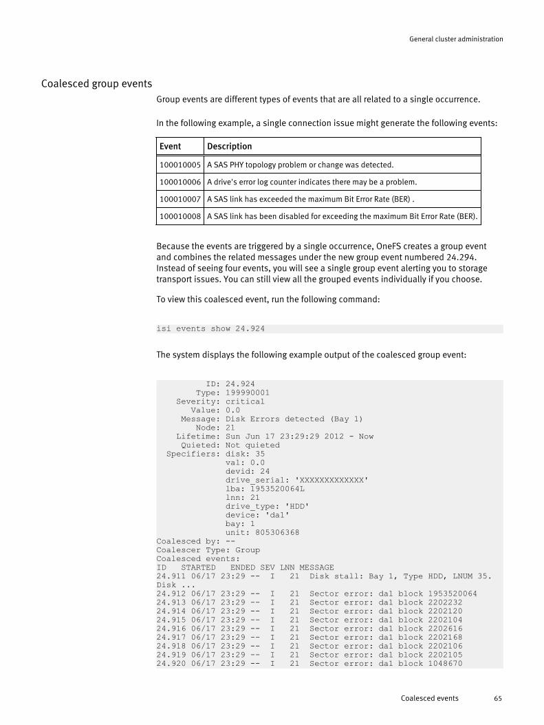
Coalesced group eventsGroup events are different types of events that are all related to a single occurrence.
In the following example, a single connection issue might generate the following events:
Event Description
100010005 A SAS PHY topology problem or change was detected.
100010006 A drive's error log counter indicates there may be a problem.
100010007 A SAS link has exceeded the maximum Bit Error Rate (BER) .
100010008 A SAS link has been disabled for exceeding the maximum Bit Error Rate (BER).
Because the events are triggered by a single occurrence, OneFS creates a group eventand combines the related messages under the new group event numbered 24.294.Instead of seeing four events, you will see a single group event alerting you to storagetransport issues. You can still view all the grouped events individually if you choose.
To view this coalesced event, run the following command:
isi events show 24.924
The system displays the following example output of the coalesced group event:
ID: 24.924 Type: 199990001 Severity: critical Value: 0.0 Message: Disk Errors detected (Bay 1) Node: 21 Lifetime: Sun Jun 17 23:29:29 2012 - Now Quieted: Not quieted Specifiers: disk: 35 val: 0.0 devid: 24 drive_serial: 'XXXXXXXXXXXXX' lba: 1953520064L lnn: 21 drive_type: 'HDD' device: 'da1' bay: 1 unit: 805306368Coalesced by: --Coalescer Type: GroupCoalesced events:ID STARTED ENDED SEV LNN MESSAGE24.911 06/17 23:29 -- I 21 Disk stall: Bay 1, Type HDD, LNUM 35. Disk ...24.912 06/17 23:29 -- I 21 Sector error: da1 block 195352006424.913 06/17 23:29 -- I 21 Sector error: da1 block 220223224.914 06/17 23:29 -- I 21 Sector error: da1 block 220212024.915 06/17 23:29 -- I 21 Sector error: da1 block 220210424.916 06/17 23:29 -- I 21 Sector error: da1 block 220261624.917 06/17 23:29 -- I 21 Sector error: da1 block 220216824.918 06/17 23:29 -- I 21 Sector error: da1 block 220210624.919 06/17 23:29 -- I 21 Sector error: da1 block 220210524.920 06/17 23:29 -- I 21 Sector error: da1 block 1048670
General cluster administration
Coalesced events 65
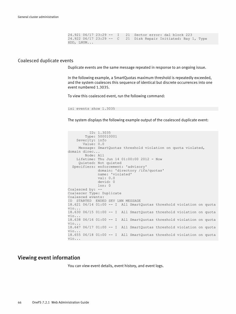
24.921 06/17 23:29 -- I 21 Sector error: da1 block 22324.922 06/17 23:29 -- C 21 Disk Repair Initiated: Bay 1, Type HDD, LNUM...
Coalesced duplicate eventsDuplicate events are the same message repeated in response to an ongoing issue.
In the following example, a SmartQuotas maximum threshold is repeatedly exceeded,and the system coalesces this sequence of identical but discrete occurrences into oneevent numbered 1.3035.
To view this coalesced event, run the following command:
isi events show 1.3035
The system displays the following example output of the coalesced duplicate event:
ID: 1.3035 Type: 500010001 Severity: info Value: 0.0 Message: SmartQuotas threshold violation on quota violated, domain direc... Node: All Lifetime: Thu Jun 14 01:00:00 2012 - Now Quieted: Not quieted Specifiers: enforcement: 'advisory' domain: 'directory /ifs/quotas' name: 'violated' val: 0.0 devid: 0 lnn: 0Coalesced by: --Coalescer Type: DuplicateCoalesced events:ID STARTED ENDED SEV LNN MESSAGE18.621 06/14 01:00 -- I All SmartQuotas threshold violation on quota vio...18.630 06/15 01:00 -- I All SmartQuotas threshold violation on quota vio...18.638 06/16 01:00 -- I All SmartQuotas threshold violation on quota vio...18.647 06/17 01:00 -- I All SmartQuotas threshold violation on quota vio...18.655 06/18 01:00 -- I All SmartQuotas threshold violation on quota vio...
Viewing event informationYou can view event details, event history, and event logs.
General cluster administration
66 OneFS 7.2.1 Web Administration Guide
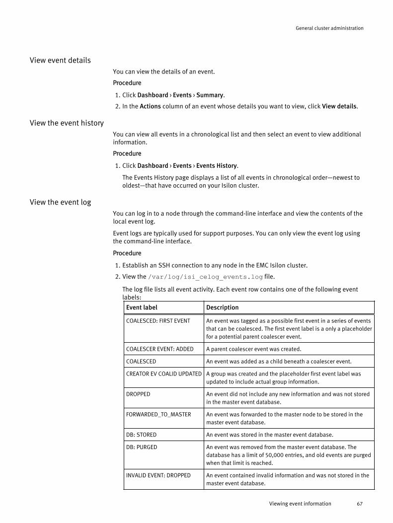
View event detailsYou can view the details of an event.
Procedure
1. Click Dashboard > Events > Summary.
2. In the Actions column of an event whose details you want to view, click View details.
View the event historyYou can view all events in a chronological list and then select an event to view additionalinformation.
Procedure
1. Click Dashboard > Events > Events History.
The Events History page displays a list of all events in chronological order—newest tooldest—that have occurred on your Isilon cluster.
View the event logYou can log in to a node through the command-line interface and view the contents of thelocal event log.
Event logs are typically used for support purposes. You can only view the event log usingthe command-line interface.
Procedure
1. Establish an SSH connection to any node in the EMC Isilon cluster.
2. View the /var/log/isi_celog_events.log file.
The log file lists all event activity. Each event row contains one of the following eventlabels:
Event label Description
COALESCED: FIRST EVENT An event was tagged as a possible first event in a series of eventsthat can be coalesced. The first event label is a only a placeholderfor a potential parent coalescer event.
COALESCER EVENT: ADDED A parent coalescer event was created.
COALESCED An event was added as a child beneath a coalescer event.
CREATOR EV COALID UPDATED A group was created and the placeholder first event label wasupdated to include actual group information.
DROPPED An event did not include any new information and was not storedin the master event database.
FORWARDED_TO_MASTER An event was forwarded to the master node to be stored in themaster event database.
DB: STORED An event was stored in the master event database.
DB: PURGED An event was removed from the master event database. Thedatabase has a limit of 50,000 entries, and old events are purgedwhen that limit is reached.
INVALID EVENT: DROPPED An event contained invalid information and was not stored in themaster event database.
General cluster administration
Viewing event information 67

Event label Description
UPDATE EVENT: DROPPED A request to update the group information in a parent coalescerevent was discontinued.
Responding to eventsYou can view event details and respond to cluster events.
You can view and manage new events, open events, and recently ended events. You canalso view coalesced events and additional, more-detailed information about a specificevent. You also can quiet or cancel events.
Quieting, unquieting, and canceling eventsYou can change an event's state by quieting, unquieting, or canceling an event.
You can select the following actions to change the state of an event:
Quiet
Acknowledges and removes the event from the list of new events and adds the eventto a list of quieted events.
Note
If a new event of the same event type is triggered, it is a separate new event andmust be quieted.
Unquiet
Returns a quieted event to an unacknowledged state in the list of new events andremoves the event from the list of quieted events.
Cancel
Permanently ends an occurrence of an event. The system cancels an event whenconditions are met that end its duration, which is bounded by a start time and anend time, or when you cancel the event manually.
Most events are canceled automatically by the system when the event reaches the end ofits duration. The event remains in the system until you manually acknowledge or quietthe event. You can acknowledge events through either the web administration interfaceor the command-line interface.
Change the status for an eventYou can change the status of an event by quieting, unquieting, or canceling it.
Procedure
1. Click Dashboard > Events > Summary.
2. Perform one of the following actions:
l To acknowledge an event, click Quiet.
l To restore an event to an unacknowledged state, click Unquiet.
l To permanently remove an occurrence of an event, click Cancel.
General cluster administration
68 OneFS 7.2.1 Web Administration Guide

Managing event notification settingsYou can view and modify event notification settings and configure batch notifications.
Event notification methodsYou can define the method by which OneFS delivers notifications.
You can send email messages to distribution lists and apply email templates tonotifications. You can also specify SMTP, authorization, and security settings.
SupportIQ
You can deliver notifications to Isilon Technical Support over HTTPS, SMTP, or both.
SNMP trap
You can send SNMP traps to one or more network monitoring stations or trapreceivers. Each event can generate one or more SNMP traps. You can downloadmanagement information base files (MIBs) from the cluster at /usr/local/share/snmp/mibs/. The ISILON-TRAP-MIB.txt file describes the traps thatthe cluster can generate, and the ISILON-MIB.txt file describes the associatedvarbinds that accompany the traps.
ESRS
You can receive alerts from EMC Secure Remote Services (ESRS), which is a secure,IP-based customer service support system.
ESRS is similar to SupportIQ and performs many of the same functions:
l Send alerts regarding the health of your devices.
l Enable support personnel to run the same scripts used by SupportIQ to gatherdata from your devices.
l Allow support personnel to establish remote access to troubleshoot your cluster.
Event notification settingsYou can specify whether you want to receive event notifications as aggregated batches oras individual notifications for each event. Batch notifications are sent every 10 seconds.
The batch options that are described in this table affect both the content and the subjectline of notification emails that are sent in response to system events. You can specifyevent notification batch options when you configure SMTP email settings.
Setting Option Description
Notification batchmode
Batch all Generates a single email for each eventnotification.
Batch by severity Generates an email that containsaggregated notifications for each event ofthe same severity, regardless of eventcategory.
Batch by category Generates an email that containsaggregated notifications for event of thesame category, regardless of severity.
General cluster administration
Managing event notification settings 69

Setting Option Description
No batching Generates one email per event.
Custom notificationtemplate
No custom notificationtemplate is set
Sends the email notification in the defaultOneFS notification template format.
Set custom notificationtemplate
Sends the email notifications in the formatthat you defined in your custom templatefile.
View event notification settingsYou can view email, SupportIQ, and contact information for event notifications.
Procedure
1. Click Dashboard > Events > Notification Settings.
Modify event notification settingsYou can modify email, SupportIQ, and contact settings for event notifications.
Procedure
1. Click Dashboard > Events > Notification Settings.
2. Click the Modify link for the setting that you want to change.
3. Click Submit.
Specify event-notification batch mode or template settingsYou can choose an event-notification batch option to specify whether you want to receivenotifications individually or as an aggregate. You also can specify a custom notificationtemplate for email notifications.
Before you begin
You must first create a custom notification template and then upload it to a directory atthe same level or below /ifs; for example, /ifs/templates.
Procedure
1. Click Cluster Management > General Settings > Email Settings.
2. In the Event Notification Settings area on the General Settings page, select aNotification batch mode option.
3. Leave the Set custom notification template field blank to use the default notificationtemplate.
4. In the Custom notification template field, select the custom event notificationtemplate.
l Click Browse, navigate to and select the template file that you want to use, andthen click OK.
l In the Set custom notification template field, type the path and file name of thetemplate file that you want to use.
5. Click Submit.
General cluster administration
70 OneFS 7.2.1 Web Administration Guide
Managing event notification rulesYou can create, modify, or delete event notification rules to determine when and how youreceive information about specific system events.
Create an event notification ruleYou can configure event notification rules based on specified events and event types.
You can configure email notification and SNMP trap generation for a specific event.
Procedure
1. Click Dashboard > Events > Event Notification Rules.
2. In the Notification Rules area on the Cluster Events page, click Add Rule.
3. In the Rule name field on the Add Notification Rule page, type a name for the rule.
4. In the Recipients area, specify a notification method.
a. To notify a recipient through email, select Email, type the email address to whichnotifications will be sent, and then click Add.
b. To notify a community through SNMP traps, select SNMP, select the communityname and the SNMP host, which is the network monitoring station, from therespective lists, and then click Add.
c. To add additional notification recipients or communities, repeat these steps.
5. In the Events area, expand the event types and select the check boxes for the eventsand event types that you want to trigger this notification.
6. Click Submit.
Send a test event notificationYou can generate a test event notification to confirm that event notifications are workingas you intend.
Procedure
1. Click Dashboard > Events > Notification Settings.
2. In the Send Test Event area on the Cluster Events page, click Send test event.
3. On the Cluster Events page, click Summary to verify whether the test event wassuccessful.
A corresponding test event notification appears in the New Events list, which appearsin the Message column as a message similar to Test event sent from WebUI.
View event notification rulesYou can view a list of event notification rules and details about specific rules.
Procedure
1. Click Dashboard > Events > Event Notification Rules.
2. In the Actions column of the rule whose settings you want to view, click Edit.
3. When you have finished viewing the rule details, click Cancel.
General cluster administration
Managing event notification rules 71
Modify an event notification ruleYou can modify event notification rules that you created. System event notification rulescannot be modified.
Procedure
1. Click Dashboard > Events > Event Notification Rules.
2. In the Actions column for the rule that you want to modify, click Edit.
3. Modify the event notification rule settings as needed.
4. Click Submit.
Delete an event notification ruleYou can delete event notification rules that you created, but system event notificationrules cannot be deleted.
Procedure
1. Click Dashboard > Events > Event Notification Rules.
2. In the Notification Rules area, in the Actions column for the rule that you want todelete, click Delete.
3. Click Yes to confirm the deletion.
Cluster maintenanceTrained service personnel can replace or upgrade components in Isilon nodes.
Isilon Technical Support can assist you with replacing node components or upgradingcomponents to increase performance.
Replacing node componentsIf a node component fails, Isilon Technical Support will work with you to quickly replacethe component and return the node to a healthy status.
Trained service personnel can replace the following field replaceable units (FRUs):
l battery
l boot flash drive
l SATA/SAS Drive
l memory (DIMM)
l fan
l front panel
l intrusion switch
l network interface card (NIC)
l InfiniBand card
l NVRAM card
l SAS controller
l power supply
General cluster administration
72 OneFS 7.2.1 Web Administration Guide

If you configure your cluster to send alerts to Isilon, Isilon Technical Support will contactyou if a component needs to be replaced. If you do not configure your cluster to sendalerts to Isilon, you must initiate a service request.
Upgrading node componentsYou can upgrade node components to gain additional capacity or performance.
Trained service personnel can upgrade the following components in the field:
l drive
l memory (DIMM)
l network interface card (NIC)
If you want to upgrade components in your nodes, contact Isilon Technical Support.
Managing drive firmwareIf the firmware of any drive in a cluster becomes obsolete, the cluster performance orhardware reliability might get affected. To ensure overall data integrity, you may updatethe drive firmware to the latest revision by installing the drive support package or thedrive firmware package.
You can determine whether the drive firmware on your cluster is of the latest revision byviewing the status of the drive firmware.
Note
We recommend that you contact EMC Isilon Technical Support before updating the drivefirmware.
Drive firmware update overviewYou can update the drive firmware through drive support packages or drive firmwarepackages.
Download and install either of these packages from http://support.emc.com dependingon the OneFS version running on your cluster and the type of drives on the nodes.
Drive Support PackageFor clusters running OneFS 7.1.1 and later, install a drive support package to update thedrive firmware. You do not need to reboot the affected nodes to complete the firmwareupdate. A drive support package provides the following additional capabilities:
l Updates the following drive configuration information:
n List of supported drives
n Drive firmware metadata
n SSD wear monitoring data
n SAS and SATA settings and attributes
l Automatically updates the drive firmware for new and replacement drives to the latestrevision before those drives are formatted and used in a cluster. This is applicableonly for clusters running OneFS 7.2 and later.
Note
Firmware of drives in use cannot be updated automatically.
General cluster administration
Upgrading node components 73
Drive Firmware PackageFor clusters running OneFS versions earlier than 7.1.1, or for clusters with non-bootflashnodes, install a cluster-wide drive firmware package to update the drive firmware. Youmust reboot the affected nodes to complete the firmware update.
Install a drive support packageFor clusters running OneFS 7.1.1 and later, install the latest drive support package toupdate your drive firmware to the latest supported revision. See the Considerations forinstalling the latest drive support package section before you begin the installation.
Procedure
1. Go to the EMC Support page that lists all the available versions of the drive supportpackage.
2. Click the latest version of the drive support package and download the file.
Note
See the Considerations for installing the latest drive support package section in orderto select the appropriate variant of the package.
3. Open a secure shell (SSH) connection to any node in the cluster and log in.
4. Create or check for the availability of the directory structure /ifs/data/Isilon_Support/dsp.
5. Copy the downloaded file to the dsp directory through SCP, FTP, SMB, NFS, or anyother supported data-access protocols.
6. Unpack the file by running the tar command.
For example, based on the variant selected for drive support package version 1.5,unpack the package by running one of the following commands:
tar -zxvf Drive_Support_v1.5.tgztar –zxvf Drive_Support_v1.5_No_SSD.tgz
7. Install the package by running the isi_dsp_install command.
For example, based on the variant selected for drive support package version 1.5,install the package by running one of the following commands:
isi_dsp_install Drive_Support_v1.5.tarisi_dsp_install Drive_Support_v1.5_No_SSD.tar
Note
l You must run the isi_dsp_install command to install the drive supportpackage. Do not use the isi pkg command.
l The installation process takes care of installing all the necessary files from thedrive support package followed by the uninstallation of the package. You do notneed to delete the package after its installation or prior to installing a later version.
General cluster administration
74 OneFS 7.2.1 Web Administration Guide
View drive firmware statusYou can view the status of the drive firmware on the cluster to determine whether youneed to update the firmware.
Procedure
1. Open a secure shell (SSH) connection to any node in the cluster and log in.
2. Perform one of the following tasks:
l To view the drive firmware status of all the nodes, run the following command:
isi drivefirmware statusl To view the drive firmware status of drives on a specific node, run the isi
devices command with the -a fwstatus option. Run the following commandto view the drive firmware status of each drive on node 1:
isi devices -a fwstatus -d 1
The output of the previous command is shown in the following example:
Node 1 Model FW Desired FWBay 1 HGST HUS724030ALA640 MF80AAC0Bay 2 HGST HUS724030ALA640 MF80AAC0Bay 3 HGST HUS724030ALA640 MF80AAC0
Run the following command to view the drive firmware status on node 1 and disk12:
isi devices -a fwstatus -d 1:12If a drive firmware update is not required, the Desired FW column is empty.
Update the drive firmwareDetermine the type of drive in the node, and then execute the update. The node restartsautomatically after the loading process is complete.
Before you begin
Install the drive firmware package.
Note
Do not restart or power off the node before the update is complete. When the updateprocess completes successfully, the node restarts automatically.
Procedure
1. Log in to the node through either a serial console port or an internal SSH connectionbetween nodes.
Note
External network interfaces are disabled as part of the reboot process. The commandin the next step will fail if you run the command from an external network interface.
2. Determine whether a drive firmware update is required by typing the followingcommand:
isi_disk_firmware_reboot
General cluster administration
Managing drive firmware 75

3. Determine whether any of the drives on the node that need to be updated are WesternDigital drives by typing the following command:
isi_radish -q
CAUTION
If you are performing a drive firmware update on Western Digital drives, you mustupdate the drives sequentially to avoid significant drive damage.
4. Type one of the following commands depending on whether the node contains anyWestern Digital drives that require a drive firmware update:
l To update the drive firmware of a node with any Western Digital drives, type thefollowing command to perform a sequential update:isi_disk_firmware_reboot -sv
l To update the drive firmware of a node without any Western Digital drives, type thefollowing command to perform a parallel update:isi_disk_firmware_reboot -p
A drive firmware update takes 20–60 seconds, depending on the drive model. A nodecontaining Western Digital drives takes approximately fifteen minutes to complete theentire process.
After the update process is complete, the node reboots automatically.If the update is unsuccessful, the LED display on the front panel of the node willindicate an error and the node will not reboot. Wait for a few minutes and then run thereboot command to reboot the node manually. If this process is unsuccessful,contact EMC Isilon Technical Support.
Verify a drive firmware updateAfter you update the drive firmware in a node, confirm that the firmware is updatedproperly and that the affected drives are operating correctly.
Procedure
1. Ensure that no drive firmware updates are currently in progress by running thefollowing command:
isi devices
If a drive is currently being updated, [FW_UPDATE] appears in the status column.
2. Verify that all drives have been updated by running the following command:
isi drivefirmware status
If all drives have been updated, the Desired FW column is empty.
3. Verify that all affected drives are operating in a healthy state by running the followingcommand:
isi devices
If a drive is operating in a healthy state, [HEALTHY] appears in the status column.
General cluster administration
76 OneFS 7.2.1 Web Administration Guide

Drive firmware status informationYou can view information about the status of the drive firmware through the OneFScommand-line interface.
The following example shows the output of the isi drivefirmware statuscommand:
Model FW Desired FW Count NodesHGST HUS724030ALA640 MF80AAC0 30 1
Where:
Model
Displays the name of the drive model.
FW
Displays the version number of the firmware currently running on the drives.
Desired FW
If the drive firmware should be upgraded, displays the version number of the drivefirmware that the firmware should be updated to.
Count
Displays the number of drives of this model that are currently running the specifieddrive firmware.
Nodes
Displays the LNNs of nodes that the specified drives exist in.
The following example shows the output of the isi devices command with the -afwstatus option:
Node 1 Model FW Desired FWBay 1 HGST HUS724030ALA640 MF80AAC0Bay 2 HGST HUS724030ALA640 MF80AAC0Bay 3 HGST HUS724030ALA640 MF80AAC0
Where:
Drive
Displays the number of the bay that the drive is in.
Note
This column is not labeled in the output. The information appears under the nodenumber.
Model
Displays the name of the drive model.
FW
Displays the version number of the firmware currently running on the drive.
General cluster administration
Managing drive firmware 77
Desired FW
Displays the version number of the drive firmware that the drive should be updatedto. If a drive firmware update is not required, the Desired FW column is empty.
Formatting a drive for OneFS compatibilityIf the Add operation fails when a drive is not formatted for OneFS, you can reformat, andadd the drive.
When adding a drive in OneFS, a message is displayed that the drive is not compatiblefor OneFS and must be formatted.Figure 1 Reformat a drive message
Procedure
1. To format and add the drive to OneFS, run the following command:
isi devices -a format
2. To complete the operation, follow the instructions when prompted.
Results
The operation can take several minutes to complete, and destroys any data on the drive.
Automatic update of drive firmwareFor clusters running OneFS 7.2 or later, install the latest drive support package on a nodeto automatically update the firmware for a new or replacement drive.
The information within the drive support package determines whether the firmware of adrive must be updated before the drive is formatted and used. If an update is available,the drive is automatically updated with the latest firmware.
Note
New and replacement drives added to a cluster are formatted regardless of the status oftheir firmware revision. You can identify a firmware update failure by viewing the firmwarestatus for the drives on a specific node. In case of a failure, run the isi devicescommand with the fwupdate action on the node to update the firmware manually. For
example, run the following command to manually update the firmware on node 1:
isi devices -a fwupdate -d 1
Managing cluster nodesYou can add and remove nodes from a cluster. You can also shut down or restart theentire cluster.
General cluster administration
78 OneFS 7.2.1 Web Administration Guide
Add a node to a clusterYou can add a new node to an existing EMC Isilon cluster.
Before you begin
Before you add a node to a cluster, verify that an internal IP address is available. Add IPaddresses as necessary before you add a new node.
If a new node is running a different version of OneFS than a cluster, the system changesthe node version of OneFS to match the cluster.
Note
For specific information about version compatibility between OneFS and EMC Isilonhardware, refer to the Isilon Supportability and Compatibility Guide.
Procedure
1. Click Cluster Management > Hardware Configuration > Add Nodes.
2. In the Available Nodes table, click Add for the node that you want to add to thecluster.
Remove a node from the clusterYou can remove a node from an EMC Isilon cluster. When you remove a node, the systemsmartfails the node to ensure that data on the node is transferred to other nodes in thecluster.
Removing a storage node from a cluster deletes the data from that node. Before thesystem deletes the data, the FlexProtect job safely redistributes data across the nodesremaining in the cluster.
Procedure
1. Navigate to Cluster Management > Hardware Configuration > Remove Nodes.
2. In the Remove Node area, specify the node you want to remove.
3. Click Submit.
If you remove a storage node, the Cluster Status area displays smartfail progress. Ifyou remove a non-storage accelerator node, it is immediately removed from thecluster.
Modify the LNN of a nodeYou can modify the logical node number (LNN) of a node. This procedure is available onlythrough the command-line interface (CLI).
The nodes within your cluster can be renamed to any name/integer between 1 and 144.By changing the name of your node, you are resetting the LNN.
Note
Although you can specify any integer as an LNN, we recommend that you do not specifyan integer greater than 144. Specifying LNNs above 144 can result in significantperformance degradation.
Procedure
1. Open a secure shell (SSH) connection to any node in the cluster and log in.
General cluster administration
Managing cluster nodes 79
2. Open the isi config command prompt by running the following command:
isi config
3. Run the lnnset command.
The following command switches the LNN of a node from 12 to 73:
lnnset 12 734. Enter commit .
Results
You might need to reconnect to your SSH session before the new node name isautomatically changed.
Shut down or restart a clusterYou can shut down or restart an entire EMC Isilon cluster.
Procedure
1. Navigate to Cluster Management > Hardware Configuration > Shutdown & RebootControls.
2. In the Shut Down or Reboot This Cluster area, specify an action:
Option Description
Shut down Shuts down the cluster.
Reboot Stops then restarts the cluster.
3. Click Submit.
Upgrading OneFSTwo options are available for upgrading the OneFS operating system: a rolling upgrade ora simultaneous upgrade. Before upgrading OneFS software, a pre-upgrade check must beperformed.
A rolling upgrade individually upgrades and restarts each node in the EMC Isilon clustersequentially. During a rolling upgrade, the cluster remains online and continues servingclients with no interruption in service, although some connection resets may occur onSMB clients. Rolling upgrades are performed sequentially by node number, so a rollingupgrade takes longer to complete than a simultaneous upgrade. The final node in theupgrade process is the node that you used to start the upgrade process.
Note
Rolling upgrades are not available for all clusters. For instructions on how to plan anupgrade, prepare the cluster for upgrade, and perform an upgrade of the operatingsystem, see the OneFS Upgrade Planning and Process Guide.
A simultaneous upgrade installs the new operating system and restarts all nodes in thecluster at the same time. Simultaneous upgrades are faster than rolling upgrades butrequire a temporary interruption of service during the upgrade process. Your data isinaccessible during the time that it takes to complete the upgrade process.
Before beginning either a simultaneous or rolling upgrade, OneFS compares the currentcluster and operating system with the new version to ensure that the cluster meets
General cluster administration
80 OneFS 7.2.1 Web Administration Guide
certain criteria, such as configuration compatibility (SMB, LDAP, SmartPools), diskavailability, and the absence of critical cluster events. If upgrading puts the cluster atrisk, OneFS warns you, provides information about the risks, and prompts you to confirmwhether to continue the upgrade.
If the cluster does not meet the pre-upgrade criteria, the upgrade does not proceed, andthe unsupported statuses are listed.
Remote supportIsilon Technical Support personnel can remotely manage your Isilon cluster totroubleshoot an open support case with your permission.
You can enable remote customer service support through SupportIQ or EMC SecureRemote Services (ESRS).
Remote support using SupportIQIsilon Technical Support personnel can remotely manage your Isilon cluster totroubleshoot an open support case with your permission. The Isilon SupportIQ moduleallows Isilon Technical Support personnel to gather diagnostic data about the cluster.
Note
SupportIQ is targeted for End of Service Life on June 30, 2016. As of OneFS 7.1, Isilonsupports EMC Secure Remote Services (ESRS) for remote connectivity. ESRS is aproactive, IP-based, bi-directional remote servicing capability for customer EMC productsthat is secure, high speed, and operates 24x7. See the ESRS section in the OneFS 7.1FAQ for more information.
Isilon Technical Support representatives run scripts that gather data about clustersettings and operations. The SupportIQ agent then uploads the information to a secureIsilon FTP site so it is available for Isilon Technical Support personnel to review. Thesescripts do not affect cluster services or data availability.
Note
The SupportIQ scripts are based on the Isilon isi_gather_info log-gathering tool.
The SupportIQ module is included with the OneFS operating system and does not requireyou to activate a separate license. You must enable and configure the SupportIQ modulebefore SupportIQ can run scripts to gather data. The feature may have been enabledwhen the cluster was first set up, but you can enable or disable SupportIQ through theIsilon web administration interface.
In addition to enabling the SupportIQ module to allow the SupportIQ agent to run scripts,you can enable remote access, which allows Isilon Technical Support personnel tomonitor cluster events and remotely manage your cluster using SSH or the webadministration interface. Remote access helps Isilon Technical Support to quickly identifyand troubleshoot cluster issues. Other diagnostic tools are available for you to use inconjunction with Isilon Technical Support to gather and upload information such aspacket capture metrics.
General cluster administration
Remote support 81
Note
If you enable remote access, you must also share cluster login credentials with IsilonTechnical Support personnel. Isilon Technical Support personnel remotely access yourcluster only in the context of an open support case and only after receiving yourpermission.
Configuring SupportIQOneFS logs contain data that Isilon Technical Support personnel can securely upload,with your permission, and then analyze to troubleshoot cluster problems. The SupportIQtechnology must be enabled and configured for this process.
When SupportIQ is enabled, Isilon Technical Support personnel can request logs throughscripts that gather cluster data and then upload the data to a secure location. You mustenable and configure the SupportIQ module before SupportIQ can run scripts to gatherdata. The feature may have been enabled when the cluster was first set up.
You can also enable remote access, which allows Isilon Technical Support personnel totroubleshoot your cluster remotely and run additional data-gathering scripts. Remoteaccess is disabled by default. To enable remote SSH access to your cluster, you mustprovide the cluster password to a Technical Support engineer.
Enable and configure SupportIQYou can enable and configure SupportIQ to allow the SupportIQ agent to run scripts thatgather and upload information about your cluster to Isilon Technical Support personnel.Optionally, you can enable remote access to your EMC Isilon cluster.
Procedure
1. Click Cluster Management > General Settings > SupportIQ.
2. In the SupportIQ Settings area, select the Enable SupportIQ check box.
3. For SupportIQ alerts, select an option.
l Send alerts via SupportIQ agent (HTTPS) and by email (SMTP) – SupportIQdelivers notifications to Isilon through the SupportIQ agent over HTTPS and byemail over SMTP.
l Send alerts via SupportIQ agent (HTTPS) – SupportIQ delivers notifications toIsilon only through the SupportIQ agent over HTTPS.
4. (Optional) Enable HTTPS proxy support for SupportIQ.
a. Select the HTTPS proxy for SupportIQ check box.
b. In the Proxy host field, type the IPv4 address, IPv6 address, or fully qualifieddomain name (FQDN) of the HTTP proxy server.
c. In the Proxy port field, type the port number on which the HTTP proxy serverreceives requests.
d. (Optional) In the Username field, type the user name for the proxy server.
e. (Optional) In the Password field, type the password for the proxy server.
5. (Optional) Enable remote access to the cluster.
a. Select the Enable remote access to cluster via SSH and web interface check box.
b. Review the remote-access end user license agreement (EULA) and, if you agree tothe terms and conditions, select the I have read and agree to check box.
6. Click Submit.
General cluster administration
82 OneFS 7.2.1 Web Administration Guide

A successful configuration is indicated by a message similar to SupportIQsettings have been updated.
Disable SupportIQYou can disable SupportIQ so the SupportIQ agent does not run scripts to gather andupload data about your EMC Isilon cluster.
Procedure
1. Click Cluster Management > General Settings > SupportIQ.
2. Clear the Enable SupportIQ check box.
3. Click Submit.
SupportIQ scriptsWhen SupportIQ is enabled, Isilon Technical Support personnel can request logs withscripts that gather cluster data and then upload the data. The SupportIQ scripts arelocated in the /usr/local/SupportIQ/Scripts/ directory on each node.
The following table lists the data-gathering activities that SupportIQ scripts perform.These scripts can be run automatically, at the request of an Isilon Technical Supportrepresentative, to collect information about your cluster's configuration settings andoperations. The SupportIQ agent then uploads the information to a secure Isilon FTP site,so that it is available for Isilon Technical Support personnel to analyze. The SupportIQscripts do not affect cluster services or the availability of your data.
Action Description
Clean watch folder Clears the contents of /var/crash.
Get application data Collects and uploads information about OneFS applicationprograms.
Generate dashboard filedaily
Generates daily dashboard information.
Generate dashboard filesequence
Generates dashboard information in the sequence that it occurred.
Get ABR data (as builtrecord)
Collects as-built information about hardware.
Get ATA control and GMirrorstatus
Collects system output and invokes a script when it receives anevent that corresponds to a predetermined eventid.
Get cluster data Collects and uploads information about overall clusterconfiguration and operations.
Get cluster events Gets the output of existing critical events and uploads theinformation.
Get cluster status Collects and uploads cluster status details.
Get contact info Extracts contact information and uploads a text file that containsit.
Get contents (var/crash) Uploads the contents of /var/crash.
Get job status Collects and uploads details on a job that is being monitored.
General cluster administration
Remote support using SupportIQ 83

Action Description
Get domain data Collects and uploads information about the cluster’s ActiveDirectory Services (ADS) domain membership.
Get file system data Collects and uploads information about the state and health of theOneFS /ifs/ file system.
Get IB data Collects and uploads information about the configuration andoperation of the InfiniBand back-end network.
Get logs data Collects and uploads only the most recent cluster log information.
Get messages Collects and uploads active /var/log/messages files.
Get network data Collects and uploads information about cluster-wide and node-specific network configuration settings and operations.
Get NFS clients Runs a command to check if nodes are being used as NFS clients.
Get node data Collects and uploads node-specific configuration, status, andoperational information.
Get protocol data Collects and uploads network status information and configurationsettings for the NFS, SMB, FTP, and HTTP protocols.
Get Pcap client stats Collects and uploads client statistics.
Get readonly status Warns if the chassis is open and uploads a text file of the eventinformation.
Get usage data Collects and uploads current and historical information aboutnode performance and resource usage.
isi_gather_info Collects and uploads all recent cluster log information.
isi_gather_info --incremental
Collects and uploads changes to cluster log information that haveoccurred since the most recent full operation.
isi_gather_info --incremental singlenode
Collects and uploads details for a single node.Prompts you for the node number.
isi_gather_infosingle node
Collects and uploads changes to cluster log information that haveoccurred since the most recent full operation.Prompts you for the node number.
Upload the dashboard file Uploads dashboard information to the secure Isilon TechnicalSupport FTP site.
Remote support using ESRSEMC Isilon clusters support enablement of EMC Secure Remote Services (ESRS).
ESRS is a secure, IP-based customer service support system. ESRS features include 24x7remote monitoring and secure authentication with AES 256-bit encryption and RSA digitalcertificates. You can select monitoring on a node-by node basis, allow or deny remotesupport sessions, and review remote customer service activities.
ESRS is similar to SupportIQ and performs many of the same functions:
l Send alerts regarding the health of your devices.
General cluster administration
84 OneFS 7.2.1 Web Administration Guide
l Enable support personnel to run the same scripts used by SupportIQ to gather datafrom your devices.
l Allow support personnel to establish remote access to troubleshoot your cluster.
You can only enable one remote support system on your Isilon cluster. We recommendESRS due to the following features:
l Manages nodes individually; you select which nodes should be managed
l Can monitor multiple EMC products.
l Preferable in a high-security environment.
See the most recent version of the document titled EMC Secure Remote Services TechnicalDescription for a complete description of ESRS features and functionality.
Additional documentation about ESRS can be found on the EMC Online Support site.
Configuring ESRS supportYou can configure support for EMC Secure Remote Services (ESRS) on your Isilon cluster.
Before configuring ESRS, at least one ESRS gateway server must be installed andconfigured. The gateway server acts as the single point of entry and exit for remotesupport activities and monitoring notifications. You can also set up a secondary gatewayserver as a failover, specify whether to use SMTP if ESRS transmission fails, and specifywhether an email should be sent upon transmission failure.
ESRS does not support IPv6 communications. To support ESRS transmissions and remoteconnections, at least one subnet on the EMC Isilon cluster must be configured for IPv4addresses. All nodes that you want managed by ESRS must have at least one networkinterface that is a member of an IPv4 subnet.
To support ESRS, you must designate a subnet as a point for remote access by supportpersonnel. We recommend that you designate a subnet that is dedicated to remoteconnections through ESRS, and that the subnet contains a static IP address pool in theSystem access zone. If you cannot dedicate a subnet for remote connections, ensure thatthe first IP address pool in the designated subnet is configured to use static IP addressesand is assigned to the System access zone.
When you enable support for ESRS on a cluster, the serial number and IP address of eachnode is sent to the gateway server. Once node information is received, you can:
l Select which nodes you want managed through ESRS with the ESRS ConfigurationTool.
l Create rules for remote support connections to Isilon nodes with the ESRS PolicyManager.
See the most recent version of the document titled EMC Secure Remote Services SitePlanning Guide for a complete description the gateway server requirements, installation,and configuration.
See the most recent version of the document titled EMC Secure Remote ServicesInstallation and Operations Guide for a complete description of the ESRS ConfigurationTool.
See the most recent version of the document titled EMC Secure Remote Services PolicyManager Operations Guide for a complete description of the ESRS Policy Manger.
Additional documentation about ESRS can be found on the EMC Online Support site.
General cluster administration
Remote support using ESRS 85
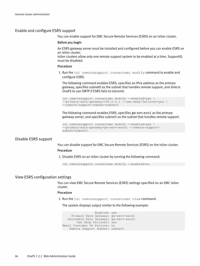
Enable and configure ESRS supportYou can enable support for EMC Secure Remote Services (ESRS) on an Isilon cluster.
Before you begin
An ESRS gateway server must be installed and configured before you can enable ESRS onan Isilon cluster.Isilon clusters allow only one remote support system to be enabled at a time. SupportIQmust be disabled.
Procedure
1. Run the isi remotesupport connectemc modify command to enable andconfigure ESRS.
The following command enables ESRS, specifies an IPv4 address as the primarygateway, specifies subnet0 as the subnet that handles remote support, and directsOneFS to use SMTP if ESRS fails to transmit:
isi remotesupport connectemc modify --enabled=yes \ --primary-esrs-gateway=192.0.2.1 --use-smtp-failover=yes \--remote-support-subnet=subnet0
The following command enables ESRS, specifies gw-serv-esrs1 as the primarygateway server, and specifies subnet5 as the subnet that handles remote support:
isi remotesupport connectemc modify --enabled=yes \ --primary-esrs-gateway=gw-serv-esrs1 --remote-support-subnet=subnet5
Disable ESRS supportYou can disable support for EMC Secure Remote Services (ESRS) on the Isilon cluster.
Procedure
1. Disable ESRS on an Isilon cluster by running the following command:
isi remotesupport connectemc modify --enabled=no
View ESRS configuration settingsYou can view EMC Secure Remote Services (ESRS) settings specified on an EMC Isiloncluster.
Procedure
1. Run the isi remotesupport connectemc view command.
The system displays output similar to the following example:
Enabled: yes Primary Esrs Gateway: gw-serv-esrs1 Secondary Esrs Gateway: gw-serv-esrs2 Use Smtp Failover: yesEmail Customer On Failure: no Remote Support Subnet: subnet0
General cluster administration
86 OneFS 7.2.1 Web Administration Guide
CHAPTER 4
Access zones
This section contains the following topics:
l Access zones overview ......................................................................................... 88l Access zone base directory rules...........................................................................88l Access zones best practices..................................................................................89l Access zone limits.................................................................................................89l Quality of service...................................................................................................90l Managing access zones........................................................................................ 90
Access zones 87
Access zones overviewAlthough the default view of an EMC Isilon cluster is that of one physical machine, youcan partition a cluster into multiple virtual containers called access zones. Access zonesallow you to isolate data and control who can access data in each zone.
Access zones support all configuration settings for authentication and identitymanagement services on a cluster, so you can configure authentication providers andprovision SMB shares and NFS exports on a zone-by-zone basis. When you create anaccess zone, a local provider is created automatically, which allows you to configure eachaccess zone with a list of local users and groups. You can also authenticate through adifferent authentication provider in each access zone.
To control data access, you can direct incoming connections to the access zone through aspecific IP address pool. Associating an access zone with an IP address pool restrictsauthentication to the associated access zone and reduces the number of available andaccessible SMB shares and NFS exports. Another advantage to multiple access zones isthe ability to configure audit protocol access for individual access zones. You can modifythe default list of successful and failed protocol audit events and then generate reportsthrough a third-party tool for an individual access zone.
A cluster includes a built-in access zone named System, where you manage all aspects ofa cluster and other access zones. By default, all cluster IP addresses connect to theSystem zone. Even if you create additional access zones, you configure all access zonesin the System zone. Role-based access, which primarily allows configuration actions, isavailable through only the System zone. All administrators, including those givenprivileges by a role, must connect to the System zone to configure a cluster.
Configuration management of a non-System access zone is not permitted through SSH,the OneFS Platform API, or the web administration interface. However, you can create anddelete SMB shares in an access zone through the Microsoft Management Console (MMC).
Access zone base directory rulesYou must assign a base directory to each access zone. A base directory defines the filesystem tree exposed by an access zone and isolates data contained in the directory tothe access zone.
A base directory path is unique for each access zone and cannot overlap or be nestedinside base directories of other access zones.
Base directories restrict configuration options for several features such as SMB sharepaths, NFS exports, the HDFS root directory, and the local provider home directorytemplate. You must observe the following rules when specifying a base directory:
l The base directory cannot be identical to the base directory of any other access zone,except the System zone. For example, you cannot specify /ifs/data/hr to boththe zone2 and zone3 access zones.
l Cannot overlap with the file system tree of a base directory in any other access zone,except the System zone. For example, if /ifs/data/hr is assigned to zone2, youcannot assign /ifs/data/hr/personnel to zone3.
l The base directory of the default System access zone is /ifs and cannot bemodified.
Access zones
88 OneFS 7.2.1 Web Administration Guide

Note
Assigning a base directory that is identical to or overlaps with the System zone isallowed, but only recommended as a temporary base directory when modifying the basedirectory path and migrating data to the new directory.
Access zones best practicesYou can avoid configuration problems on the EMC Isilon cluster when creating accesszones by following best practices guidelines.
Best practice Details
Create unique base directories. The base directory path of each access zone must be uniqueand cannot overlap or be nested inside the base directory ofanother access zone.
Separate the function of theSystem zone from other accesszones.
If you choose to create any additional access zones, do notallow data access in both the System zone and created zones.Reserve the System zone for configuration access, and createadditional zones for data access. Move current data out of theSystem zone and into a new access zone.
Create access zones to isolatedata access for different clientsor users.
Do not create access zones if a workflow requires data sharingbetween different classes of clients or users.
Assign only one authenticationprovider of each type to eachaccess zone.
An access zone is limited to a single Active Directory provider;however, OneFS allows multiple LDAP, NIS, and fileauthentication providers in each access zone. It isrecommended that you assign only one type of each providerper access zone in order to simplify administration.
Avoid overlapping UID or GIDranges for authenticationproviders in the same accesszone.
The potential for zone access conflicts is slight but possible ifoverlapping UIDs/GIDs are present in the same access zone.
Configure a single DNS serverfor all access zones.
OneFS does not support one DNS server per access zone. It isrecommended that all access zones point to a single DNSserver.
Access zone limitsYou can follow access zone limits guidelines to help size the workloads on the OneFSsystem.
If you configure multiple access zones on an EMC Isilon cluster, limits guidelines arerecommended for optimal system performance. The limits described in the EMC IsilonGuidelines for Large Workloads publication are recommended for heavy enterpriseworkflows on a cluster, treating each access zone as a separate physical machine.
Access zones
Access zones best practices 89

Quality of serviceYou can set upper bounds on quality of service by assigning specific physical resourcesto each access zone.
Quality of service addresses physical hardware performance characteristics that can bemeasured, improved, and sometimes guaranteed. Characteristics measured for quality ofservice include but are not limited to throughput rates, CPU usage, and disk capacity.When you share physical hardware in an EMC Isilon cluster across multiple virtualinstances, competition exists for the following services:
l CPU
l Memory
l Network bandwidth
l Disk I/O
l Disk capacity
Access zones do not provide logical quality of service guarantees to these resources, butyou can partition these resources between access zones on a single cluster. The followingtable describes a few ways to partition resources to improve quality of service:
Use Notes
NICs You can assign specific NICs on specific nodes to an IP address pool that isassociated with an access zone. By assigning these NICs, you can determine thenodes and interfaces that are associated with an access zone. This enables theseparation of CPU, memory, and network bandwidth.
SmartPools SmartPools are separated by node hardware equivalence classes, usually intomultiple tiers of high, medium, and low performance. The data written to aSmartPool is written only to the disks in the nodes of that pool.Associating an IP address pool with only the nodes of a single SmartPool enablespartitioning of disk I/O resources.
SmartQuotas Through SmartQuotas, you can limit disk capacity by a user or a group or in adirectory. By applying a quota to an access zone's base directory, you can limitdisk capacity used in that access zone.
Managing access zonesYou can create access zones on the EMC Isilon cluster, view and modify access zonesettings, and delete access zones.
Create an access zoneYou can create an access zone and define a base directory and authentication providers.
Procedure
1. Click Access > Access Zones.
2. Click Create an access zone.
3. In the Access Zone Name field, type a name for the access zone.
Access zones
90 OneFS 7.2.1 Web Administration Guide
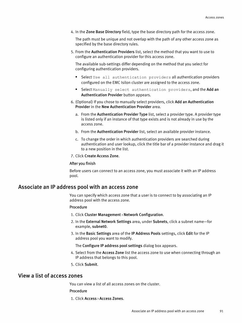
4. In the Zone Base Directory field, type the base directory path for the access zone.
The path must be unique and not overlap with the path of any other access zone asspecified by the base directory rules.
5. From the Authentication Providers list, select the method that you want to use toconfigure an authentication provider for this access zone.
The available sub-settings differ depending on the method that you select forconfiguring authentication providers.
l Select Use all authentication providers all authentication providersconfigured on the EMC Isilon cluster are assigned to the access zone.
l Select Manually select authentication providers, and the Add anAuthentication Provider button appears.
6. (Optional) If you chose to manually select providers, click Add an AuthenticationProvider in the New Authentication Provider area.
a. From the Authentication Provider Type list, select a provider type. A provider typeis listed only if an instance of that type exists and is not already in use by theaccess zone.
b. From the Authentication Provider list, select an available provider instance.
c. To change the order in which authentication providers are searched duringauthentication and user lookup, click the title bar of a provider instance and drag itto a new position in the list.
7. Click Create Access Zone.
After you finish
Before users can connect to an access zone, you must associate it with an IP addresspool.
Associate an IP address pool with an access zoneYou can specify which access zone that a user is to connect to by associating an IPaddress pool with the access zone.
Procedure
1. Click Cluster Management > Network Configuration.
2. In the External Network Settings area, under Subnets, click a subnet name—forexample, subnet0.
3. In the Basic Settings area of the IP Address Pools settings, click Edit for the IPaddress pool you want to modify.
The Configure IP address pool settings dialog box appears.
4. Select from the Access Zone list the access zone to use when connecting through anIP address that belongs to this pool.
5. Click Submit.
View a list of access zonesYou can view a list of all access zones on the cluster.
Procedure
1. Click Access > Access Zones.
Access zones
Associate an IP address pool with an access zone 91

2. Click View details for more information about a specific access zone.
Modify an access zoneYou can modify the properties of any access zone with one exception: You cannot changethe name of the built-in System zone.
Procedure
1. Click Access > Access Zones.
2. For the access zone whose settings you want to modify, click View details.
3. For each setting that you want to modify, click Edit, make the change, and then clickSave.
Delete an access zoneYou can delete any access zone except the built-in System zone. When you delete anaccess zone, all associated authentication providers remain available to other zones, butIP addresses are not reassigned to other zones. SMB shares, NFS exports, and HDFS datapaths are deleted when you delete an access zone; however, the directories and data stillexist, and you can map new shares, exports, or paths in another access zone.
Procedure
1. Click Access > Access Zones.
2. From the table of access zones, click Delete next to the access zone that you want todelete.
3. In the Confirm Delete dialog box, click Delete.
Access zones
92 OneFS 7.2.1 Web Administration Guide
CHAPTER 5
Authentication
This section contains the following topics:
l Authentication...................................................................................................... 94l Authentication provider features........................................................................... 94l Supported authentication providers...................................................................... 94l Active Directory..................................................................................................... 95l LDAP..................................................................................................................... 95l NIS........................................................................................................................96l Kerberos authentication........................................................................................ 96l File provider.......................................................................................................... 97l Local provider....................................................................................................... 97l Managing Active Directory providers......................................................................98l Managing LDAP providers....................................................................................100l Managing NIS providers...................................................................................... 105l Managing MIT Kerberos authentication............................................................... 106l Managing file providers.......................................................................................112l Managing local users and groups........................................................................ 117
Authentication 93
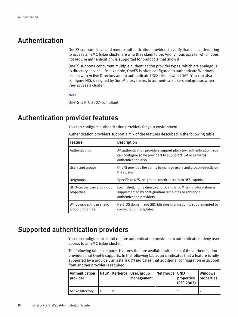
AuthenticationOneFS supports local and remote authentication providers to verify that users attemptingto access an EMC Isilon cluster are who they claim to be. Anonymous access, which doesnot require authentication, is supported for protocols that allow it.
OneFS supports concurrent multiple authentication provider types, which are analogousto directory services. For example, OneFS is often configured to authenticate Windowsclients with Active Directory and to authenticate UNIX clients with LDAP. You can alsoconfigure NIS, designed by Sun Microsystems, to authenticate users and groups whenthey access a cluster.
Note
OneFS is RFC 2307-compliant.
Authentication provider featuresYou can configure authentication providers for your environment.
Authentication providers support a mix of the features described in the following table.
Feature Description
Authentication All authentication providers support plain-text authentication. Youcan configure some providers to support NTLM or Kerberosauthentication also.
Users and groups OneFS provides the ability to manage users and groups directly onthe cluster.
Netgroups Specific to NFS, netgroups restrict access to NFS exports.
UNIX-centric user and groupproperties
Login shell, home directory, UID, and GID. Missing information issupplemented by configuration templates or additionalauthentication providers.
Windows-centric user andgroup properties
NetBIOS domain and SID. Missing information is supplemented byconfiguration templates.
Supported authentication providersYou can configure local and remote authentication providers to authenticate or deny useraccess to an EMC Isilon cluster.
The following table compares features that are available with each of the authenticationproviders that OneFS supports. In the following table, an x indicates that a feature is fullysupported by a provider; an asterisk (*) indicates that additional configuration or supportfrom another provider is required.
Authenticationprovider
NTLM Kerberos User/groupmanagement
Netgroups UNIXproperties(RFC 2307)
Windowsproperties
Active Directory x x * x
Authentication
94 OneFS 7.2.1 Web Administration Guide
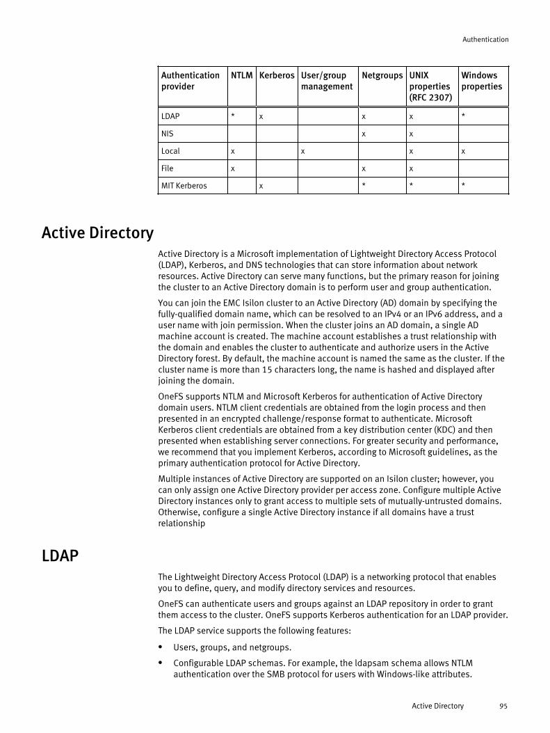
Authenticationprovider
NTLM Kerberos User/groupmanagement
Netgroups UNIXproperties(RFC 2307)
Windowsproperties
LDAP * x x x *
NIS x x
Local x x x x
File x x x
MIT Kerberos x * * *
Active DirectoryActive Directory is a Microsoft implementation of Lightweight Directory Access Protocol(LDAP), Kerberos, and DNS technologies that can store information about networkresources. Active Directory can serve many functions, but the primary reason for joiningthe cluster to an Active Directory domain is to perform user and group authentication.
You can join the EMC Isilon cluster to an Active Directory (AD) domain by specifying thefully-qualified domain name, which can be resolved to an IPv4 or an IPv6 address, and auser name with join permission. When the cluster joins an AD domain, a single ADmachine account is created. The machine account establishes a trust relationship withthe domain and enables the cluster to authenticate and authorize users in the ActiveDirectory forest. By default, the machine account is named the same as the cluster. If thecluster name is more than 15 characters long, the name is hashed and displayed afterjoining the domain.
OneFS supports NTLM and Microsoft Kerberos for authentication of Active Directorydomain users. NTLM client credentials are obtained from the login process and thenpresented in an encrypted challenge/response format to authenticate. MicrosoftKerberos client credentials are obtained from a key distribution center (KDC) and thenpresented when establishing server connections. For greater security and performance,we recommend that you implement Kerberos, according to Microsoft guidelines, as theprimary authentication protocol for Active Directory.
Multiple instances of Active Directory are supported on an Isilon cluster; however, youcan only assign one Active Directory provider per access zone. Configure multiple ActiveDirectory instances only to grant access to multiple sets of mutually-untrusted domains.Otherwise, configure a single Active Directory instance if all domains have a trustrelationship
LDAPThe Lightweight Directory Access Protocol (LDAP) is a networking protocol that enablesyou to define, query, and modify directory services and resources.
OneFS can authenticate users and groups against an LDAP repository in order to grantthem access to the cluster. OneFS supports Kerberos authentication for an LDAP provider.
The LDAP service supports the following features:
l Users, groups, and netgroups.
l Configurable LDAP schemas. For example, the ldapsam schema allows NTLMauthentication over the SMB protocol for users with Windows-like attributes.
Authentication
Active Directory 95
l Simple bind authentication, with and without SSL.
l Redundancy and load balancing across servers with identical directory data.
l Multiple LDAP provider instances for accessing servers with different user data.
l Encrypted passwords.
l IPv4 and IPv6 server URIs.
NISThe Network Information Service (NIS) provides authentication and identity uniformityacross local area networks. OneFS includes an NIS authentication provider that enablesyou to integrate the cluster with your NIS infrastructure.
NIS, designed by Sun Microsystems, can authenticate users and groups when theyaccess the cluster. The NIS provider exposes the passwd, group, and netgroup maps froman NIS server. Hostname lookups are also supported. You can specify multiple servers forredundancy and load balancing.
Note
NIS is different from NIS+, which OneFS does not support.
Kerberos authenticationKerberos is a network authentication provider that negotiates encryption tickets forsecuring a connection. OneFS supports Microsoft Kerberos and MIT Kerberosauthentication providers on an EMC Isilon cluster. If you configure an Active Directoryprovider, support for Microsoft Kerberos authentication is provided automatically. MITKerberos works independently of Active Directory.
For MIT Kerberos authentication, you define an administrative domain known as a realm.Within this realm, an authentication server has the authority to authenticate a user, host,or service; the server can resolve to either IPv4 or IPv6 addresses. You can optionallydefine a Kerberos domain to allow additional domain extensions to be associated with arealm.
The authentication server in a Kerberos environment is called the Key Distribution Center(KDC) and distributes encrypted tickets. When a user authenticates with an MIT Kerberosprovider within a realm, an encrypted ticket with the user's service principal name (SPN)is created and validated to securely pass the user's identification for the requestedservice.
You can include an MIT Kerberos provider in specific access zones for authentication.Each access zone may include at most one MIT Kerberos provider. You can discontinueauthentication through an MIT Kerberos provider by removing the provider from all thereferenced access zones.
Keytabs and SPNs overviewA Key Distribution Center (KDC) is an authentication server that stores accounts andkeytabs for users connecting to a network service within an EMC Isilon cluster. A keytab isa key table that stores keys to validate and encrypt Kerberos tickets.
One of the fields in a keytab entry is a service principal name (SPN). An SPN identifies aunique service instance within a cluster. Each SPN is associated with a specific key in theKDC. Users can use the SPN and its associated keys to obtain Kerberos tickets thatenable access to various services on the cluster. A member of the SecurityAdmin role can
Authentication
96 OneFS 7.2.1 Web Administration Guide

create new keys for the SPNs and modify them later as necessary. An SPN for a servicetypically appears as <service>/<fqdn>@<realm>.
Note
SPNs must match the SmartConnect zone name and the FQDN hostname of the cluster. Ifthe SmartConnect zone settings are changed, you must update the SPNs on the cluster tomatch the changes.
MIT Kerberos protocol supportMIT Kerberos supports certain standard network communication protocols such as HTTP,HDFS, and NFS. MIT Kerberos does not support SMB, SSH, and FTP protocols.
For the NFS protocol support, MIT Kerberos must be enabled for an export and also aKerberos provider must be included within the access zone.
File providerA file provider enables you to supply an authoritative third-party source of user and groupinformation to an EMC Isilon cluster. A third-party source is useful in UNIX and Linuxenvironments that synchronize /etc/passwd, /etc/group, and etc/netgroupfiles across multiple servers.
Standard BSD /etc/spwd.db and /etc/group database files serve as the fileprovider backing store on a cluster. You generate the spwd.db file by running thepwd_mkdb command in the OneFS command-line interface (CLI). You can script updatesto the database files.
On an Isilon cluster, a file provider hashes passwords with libcrypt. For the bestsecurity, we recommend that you use the Modular Crypt Format in the source /etc/passwd file to determine the hashing algorithm. OneFS supports the followingalgorithms for the Modular Crypt Format:
l MD5
l NT-Hash
l SHA-256
l SHA-512
For information about other available password formats, run the man 3 cryptcommand in the CLI to view the crypt man pages.
Note
The built-in System file provider includes services to list, manage, and authenticateagainst system accounts such as root, admin, and nobody. We recommended that you donot modify the System file provider.
Local providerThe local provider provides authentication and lookup facilities for user accounts addedby an administrator.
Local authentication is useful when Active Directory, LDAP, or NIS directory services arenot configured or when a specific user or application needs access to the cluster. Localgroups can include built-in groups and Active Directory groups as members.
Authentication
MIT Kerberos protocol support 97
In addition to configuring network-based authentication sources, you can manage localusers and groups by configuring a local password policy for each node in the cluster.OneFS settings specify password complexity, password age and re-use, and password-attempt lockout policies.
Managing Active Directory providersYou can view, configure, modify, and delete Active Directory providers. OneFS includes aKerberos configuration file for Active Directory in addition to the global Kerberosconfiguration file, both of which you can configure through the command-line interface.You can discontinue authentication through an Active Directory provider by removing itfrom all access zones that are using it.
Configure an Active Directory providerYou can configure one or more Active Directory providers, each of which must be joined toa separate Active Directory domain. By default, when you configure an Active Directoryprovider, it is automatically added to the System access zone.
Note
Consider the following information when you configure an Active Directory provider:
l When you join Active Directory from OneFS, cluster time is updated from the ActiveDirectory server, as long as an NTP server has not been configured for the cluster.
l If you migrate users to a new or different Active Directory domain, you must re-set theACL domain information after you configure the new provider. You can use third-partytools such as Microsoft SubInACL.
Procedure
1. Click Access > Authentication Providers > Active Directory.
2. Click Join a domain.
3. In the Domain Name field, specify the fully-qualified Active Directory domain name,which can be resolved to an IPv4 or an IPv6 address.
The domain name will also be used as the provider name.
4. In the User field, type the username of an account that is authorized to join the ActiveDirectory domain.
5. In the Password field, type the password of the user account.
6. (Optional) In the Organizational Unit field, type the name of the organizational unit(OU) to connect to on the Active Directory server. Specify the OU in the format OuNameor OuName1/SubName2.
7. (Optional) In the Machine Account field, type the name of the machine account.
Note
If you specified an OU to connect to, the domain join will fail if the machine accountdoes not reside in the OU.
8. (Optional) To enable Active Directory authentication for NFS, select the Enable SecureNFS check box.
Authentication
98 OneFS 7.2.1 Web Administration Guide
Note
If you specified an OU to connect to, the domain join will fail if the machine accountdoes not reside in the OU.
If you enable this setting, OneFS registers NFS service principal names (SPNs) duringthe domain join.
9. (Optional) To configure advanced settings, click Advanced Active Directory Settings.
10. Click Join.
Modify an Active Directory providerYou can modify the advanced settings for an Active Directory provider.
Procedure
1. Click Access > Authentication Providers > Active Directory.
2. In the Active Directory Providers table, click View details for the provider whosesettings you want to modify.
3. Click Advanced Active Directory Settings.
4. For each setting that you want to modify, click Edit, make the change, and then clickSave.
5. (Optional) Click Close.
Delete an Active Directory providerWhen you delete an Active Directory provider, you disconnect the cluster from the ActiveDirectory domain that is associated with the provider, disrupting service for users whoare accessing it. After you leave an Active Directory domain, users can no longer accessthe domain from the cluster.
Procedure
1. Click Access > Authentication Providers > Active Directory.
2. In the Active Directory Providers table, click Leave for the domain you want to leave.
3. In the confirmation dialog box, click Leave.
Active Directory provider settingsYou can view or modify the advanced settings for an Active Directory provider.
Setting Description
Services For UNIX Specifies whether to support RFC 2307 attributes for domaincontrollers. RFC 2307 is required for Windows UNIX Integration andServices For UNIX technologies.
Map to primary domain Enables the lookup of unqualified user names in the primary domain.If this setting is not enabled, the primary domain must be specifiedfor each authentication operation.
Ignore trusted domains Ignores all trusted domains.
Trusted Domains Specifies trusted domains to include if the Ignore TrustedDomains setting is enabled.
Authentication
Modify an Active Directory provider 99
Setting Description
Domains to Ignore Specifies trusted domains to ignore even if the Ignore TrustedDomains setting is disabled.
Send notification whendomain is unreachable
Sends an alert as specified in the global notification rules.
Use enhanced privacy andencryption
Encrypts communication to and from the domain controller.
Home Directory Naming Specifies the path to use as a template for naming home directories.The path must begin with /ifs and can contain variables, such as
%U, that are expanded to generate the home directory path for theuser.
Create home directorieson first login
Creates a home directory the first time that a user logs in if a homedirectory does not already exist for the user.
UNIX Shell Specifies the path to the login shell to use if the Active Directoryserver does not provide login-shell information. This setting appliesonly to users who access the file system through SSH.
Query all other providersfor UID
If no UID is available in the Active Directory, looks up Active Directoryusers in all other providers for allocating a UID.
Match users withlowercase
If no UID is available in the Active Directory, normalizes ActiveDirectory user names to lowercase before lookup.
Auto-assign UIDs If no UID is available in the Active Directory, enables UID allocationfor unmapped Active Directory users.
Query all other providersfor GID
If no GID is available in the Active Directory, looks up Active Directorygroups in all other providers before allocating a GID.
Match groups withlowercase
If no GID is available in the Active Directory, normalizes ActiveDirectory group names to lowercase before lookup.
Auto-assign GIDs If no GID is available in the Active Directory, enables GID allocationfor unmapped Active Directory groups.
Make UID/GIDassignments for users andgroups in these specificdomains
Restricts user and group lookups to the specified domains.
Managing LDAP providersYou can view, configure, modify, and delete LDAP providers. You can discontinueauthentication through an LDAP provider by removing it from all access zones that areusing it.
Authentication
100 OneFS 7.2.1 Web Administration Guide
Configure an LDAP providerBy default, when you configure an LDAP provider, it is automatically added to the Systemaccess zone.
Procedure
1. Click Access > Authentication Providers > LDAP.
2. Click Add an LDAP provider.
3. In the LDAP Provider Name field, type a name for the provider.
4. In the Server URIs field, type one or more valid LDAP server URIs, one per line, in theformat ldaps://<server>:<port> (secure LDAP) or ldap://<server>:<port> (non-secureLDAP). An LDAP server URI can be specified as an IPv4 address, IPv6 address, orhostname.
Note
l If you do not specify a port, the default port is used. The default port for non-secure LDAP (ldap://) is 389; for secure LDAP (ldaps://), it is 636. If you specifynon-secure LDAP, the bind password is transmitted to the server in clear text.
l If you specify an IPv6 address, the address must be enclosed in square brackets.For example, ldap://[2001:DB8:170:7cff::c001] is the correct IPv6 format for thisfield.
5. (Optional) Configure the following settings as needed.
Load balance servers
Select the check box to connect to a random server, or clear the check box toconnect according to the order in which the servers are listed in the Servers field.
Base Distinguished Name
Type the distinguished name (DN) of the entry at which to start LDAP searches.Base DNs can include cn (Common Name), l (Locality), dc (Domain Component),ou (Organizational Unit), or other components. For example, dc=emc,dc=com isa base DN for emc.com.
Bind to
Type the distinguished name of the entry at which to bind to the LDAP server.
Password
Specify the password to use when binding to the LDAP server. Use of thispassword does not require a secure connection; if the connection is not usingTransport Layer Security (TLS), the password is sent in clear text.
6. (Optional) To modify the default settings for user, group, and netgroup queries, clickDefault Query Settings.
7. (Optional) To modify the settings for user queries and home directory provisioning,click User Query Settings.
8. (Optional) To modify the settings for group queries, click Group Query Settings.
9. (Optional) To modify the settings for netgroup queries, click Netgroup Query Settings.
10. (Optional) To modify the default LDAP attributes that contain user information or tomodify LDAP security settings, click Advanced LDAP Settings.
Authentication
Configure an LDAP provider 101
11. Click Add LDAP Provider.
Modify an LDAP providerYou can modify any setting for an LDAP provider except its name. You must specify atleast one server for the provider to be enabled.
Procedure
1. Click Access > Authentication Providers > LDAP.
2. In the LDAP Providers table, click View details for the provider whose settings youwant to modify.
3. For each setting that you want to modify, click Edit, make the change, and then clickSave.
4. (Optional) Click Close.
Delete an LDAP providerWhen you delete an LDAP provider, it is removed from all the access zones. As analternative, you can stop using an LDAP provider by removing it from each access zonethat contains it so that the provider remains available for future use.
Procedure
1. Click Access > Authentication Providers > LDAP.
2. In the LDAP Providers table, click Delete for the provider you want to delete.
3. In the confirmation dialog box, click Delete.
LDAP query settingsYou can configure the entry point and depth at which to search for LDAP users, groups,and netgroups. You also can configure the settings for user home directory provisioning.
Note
OneFS is RFC 2307-compliant.
Distinguished Name
Specifies the base distinguished name (base DN) of the entry at which to start LDAPsearches for user, group, or netgroup objects. Base DNs can include cn (CommonName), l (Locality), dc (Domain Component), ou (Organizational Unit), or othercomponents. For example, dc=emc,dc=com is a base DN for emc.com.
Search Scope
Specifies the depth from the base DN at which to perform LDAP searches.The following values are valid:
defaultApplies the search scope that is defined in the default query settings. Thisoption is not available for the default query search scope.
baseSearches only the entry at the base DN.
onelevelSearches all entries exactly one level below the base DN.
Authentication
102 OneFS 7.2.1 Web Administration Guide

subtreeSearches the base DN and all entries below it.
childrenSearches all entries below the base DN, excluding the base DN itself.
Search Timeout
Specifies the number of seconds after which to stop retrying and fail a search. Thedefault value is 100. This setting is available only in the default query settings.
Query Filter
Specifies the LDAP filter for user, group, or netgroup objects. This setting is notavailable in the default query settings.
Authenticate users from this provider
Specifies whether to allow the provider to respond to authentication requests. Thissetting is available only in the user query settings.
Home Directory Naming
Specifies the path to use as a template for naming home directories. The path mustbegin with /ifs and can contain variables, such as %U, that are expanded togenerate the home directory path for the user. This setting is available only in theuser query settings.
Create home directories on first login
Specifies whether to create a home directory the first time a user logs in, if a homedirectory does not already exist for the user. This setting is available only in the userquery settings.
UNIX Shell
Specifies the path to the user's login shell, for users who access the file systemthrough SSH. This setting is available only in the user query settings.
LDAP advanced settingsYou can configure LDAP security settings and specify the LDAP attributes that containuser information.
Note
OneFS is RFC 2307-compliant.
Name Attribute
Specifies the LDAP attribute that contains UIDs, which are used as login names. Thedefault value is uid.
Common Name Attribute
Specifies the LDAP attribute that contains common names (CNs). The default value iscn.
Email Attribute
Specifies the LDAP attribute that contains email addresses. The default value ismail.
Authentication
LDAP advanced settings 103

GECOS Field Attribute
Specifies the LDAP attribute that contains GECOS fields. The default value is gecos.
UID Attribute
Specifies the LDAP attribute that contains UID numbers. The default value isuidNumber.
GID Attribute
Specifies the LDAP attribute that contains GIDs. The default value is gidNumber.
Home Directory Attribute
Specifies the LDAP attribute that contains home directories. The default value ishomeDirectory.
UNIX Shell Attribute
Specifies the LDAP attribute that contains UNIX login shells. The default value isloginShell.
Member Of Attribute
Sets the attribute to be used when searching LDAP for reverse memberships. ThisLDAP value should be an attribute of the user type posixAccount that describes thegroups in which the POSIX user is a member. This setting has no default value.
Netgroup Members Attribute
Specifies the LDAP attribute that contains netgroup members. The default value ismemberNisNetgroup.
Netgroup Triple Attribute
Specifies the LDAP attribute that contains netgroup triples. The default value isnisNetgroupTriple.
Group Members Attribute
Specifies the LDAP attribute that contains group members. The default value ismemberUid.
Unique Group Members Attribute
Specifies the LDAP attribute that contains unique group members. This attribute isused to determine which groups a user belongs to if the LDAP server is queried bythe user’s DN instead of the user’s name. This setting has no default value.
Alternate Security Identities Attribute
Specifies the name to be used when searching for alternate security identities. Thisname is used when OneFS attempts to resolve a Kerberos principal to a user. Thissetting has no default value.
UNIX Password Attribute
Specifies the LDAP attribute that contains UNIX passwords. This setting has nodefault value.
Windows Password Attribute
Specifies the LDAP attribute that contains Windows passwords. A commonly usedvalue is ntpasswdhash.
Certificate Authority File
Specifies the full path to the root certificates file.
Authentication
104 OneFS 7.2.1 Web Administration Guide
Require secure connection for passwords
Specifies whether to require a Transport Layer Security (TLS) connection.
Ignore TLS Errors
Continues over a secure connection even if identity checks fail.
Managing NIS providersYou can view, configure, and modify NIS providers or delete providers that are no longerneeded. You can discontinue authentication through an NIS provider by removing it fromall access zones that are using it.
Configure an NIS providerBy default, when you configure an NIS provider it is automatically added to the Systemaccess zone.
Procedure
1. Click Access > Authentication Providers > NIS.
2. Click Add a NIS provider.
3. In the NIS Provider Name field, type a name for the provider.
4. In the Servers field, type one or more valid IPv4 addresses, host names, or fullyqualified domain names (FQDNs), separated by commas.
Note
If the Load balance servers option is not selected, servers are accessed in the order inwhich they are listed.
5. In the NIS Domain field, type the domain name.
6. (Optional) Configure the Load balance servers setting:
l To connect to a random server, select the check box.
l To connect according to the order in which the servers are listed in the Serversfield, clear the check box.
7. (Optional) Specify the Default Query Settings.
a. In the Search Timeout field, specifies the number of seconds after which to stopretrying and fail a search. The default value is 20.
b. In the Retry Frequency field, specify the timeout period in seconds after which arequest will be retried. The default value is 5.
8. (Optional) Specify the User Query Settings.
a. Select the Authenticate users from this provider check box to allow the provider torespond to authentication requests.
b. Type a path in the Home Directory Naming field to use as a template for naminghome directories. The path must begin with /ifs and can contain expansionvariables, such as %U, which expand to generate the home directory path for theuser. For more information, see the Home directories section.
Authentication
Managing NIS providers 105
c. Select the Create home directories on first login check box to specify whether tocreate a home directory the first time a user logs in, if a home directory does notalready exist for the user.
d. Select a path from the UNIX Shell list to specify the path to the user's login shellfor users who access the file system through SSH.
9. (Optional) Click Host Name Query Settings and then configure the Resolve hosts fromthis provider setting:
l To enable host resolution, select the check box.
l To disable host resolution, clear the check box.
10. Click Add NIS provider.
Modify an NIS providerYou can modify any setting for an NIS provider except its name. You must specify at leastone server for the provider to be enabled.
Procedure
1. Click Access > Authentication Providers > NIS.
2. In the NIS Providers table, click View details for the provider whose settings you wantto modify.
3. For each setting that you want to modify, click Edit, make the change, and then clickSave.
4. Click Close.
Delete an NIS providerWhen you delete an NIS provider, it is removed from all access zones. As an alternative,you can stop using an NIS provider by removing it from each access zone that contains itso that the provider remains available for future use.
Procedure
1. Click Access > Authentication Providers > NIS.
2. In the NIS Providers table, click Delete for the provider that you want to delete.
3. In the confirmation dialog box, click Delete.
Managing MIT Kerberos authenticationYou can configure an MIT Kerberos provider for authentication without Active Directory.Configuring an MIT Kerberos provider involves creating an MIT Kerberos realm, creating aprovider, and joining a predefined realm. Optionally, you can configure an MIT Kerberosdomain for the provider. You can also update the encryption keys if there are anyconfiguration changes to the Kerberos provider. You can include the provider in one ormore access zones.
Managing MIT Kerberos realmsAn MIT Kerberos realm is an administrative domain that defines the boundaries withinwhich an authentication server has the authority to authenticate a user or service. Youcan create, view, edit, or delete a realm. As a best practice, specify a realm name usinguppercase characters.
Authentication
106 OneFS 7.2.1 Web Administration Guide
Create an MIT Kerberos realmAn MIT Kerberos realm is an administrative domain that defines the boundaries withinwhich an authentication server has the authority to authenticate a user or service. Youcan create a realm by defining a Key Distribution Center (KDC) and an administrativeserver.
Procedure
1. Click Access > Authentication Providers > Kerberos Provider.
2. Click Create a Kerberos Realm.
3. In the Realm Name field, type a domain name in uppercase characters. For example,CLUSTER-NAME.COMPANY.COM.
4. Select the Set as the default realm check box to set the realm as the default.
5. In the Key Distribution Centers (KDCs) field add one or more KDCs by specifying theIPv4 address, IPv6 address, or the hostname of each server.
6. (Optional) In the Admin Server field, specify the IPv4 address, IPv6 address, orhostname of the administration server, which will be fulfill the role of master KDC. Ifyou omit this step, the first KDC that you added previously is used as the defaultadministrative server.
7. (Optional) In the Default Domain field, specify the domain name to use for translatingthe service principal names.
8. Click Create Realm.
Modify an MIT Kerberos realmYou can modify an MIT Kerberos realm by modifying the Key Distribution Center (KDC) andthe administrative server settings for that realm.
Procedure
1. Click Access > Authentication Providers > Kerberos Provider.
2. In the Kerberos Realms table, select a realm and click View / Edit.
3. In the View a Kerberos Realm page, click Edit Realm.
4. Select or clear the Set as the default realm check box to modify the default realmsetting.
5. In the Key Distribution Centers (KDCs) field, specify the IPv4 address, IPv6 address, orthe hostname of each additional KDC server.
6. In the Admin Server field, specify the IPv4 address, IPv6 address, or hostname of theadministration server, which will be fulfill the role of master KDC.
7. In the Default Domain field, specify an alternate domain name for translating theservice principal names (SPNs).
8. Click Save Changes to return to the View a Kerberos Realm page.
9. Click Close.
View an MIT Kerberos realmYou can view details related to the name, Key Distribution Centers (KDCs), andadministrative server associated with an MIT Kerberos realm.
Procedure
1. Click Access > Authentication Providers > Kerberos Provider.
Authentication
Managing MIT Kerberos realms 107
2. In the Kerberos Realms table, select a realm and click View / Edit to view theinformation associated with the realm.
Delete an MIT Kerberos realmYou can delete one or more MIT Kerberos realms and all the associated MIT Kerberosdomains. Kerberos realms are referenced by Kerberos providers. Hence before you deletea realm for which you have created a provider, you must first delete that provider.
Procedure
1. Click Access > Authentication Providers > Kerberos Provider.
2. In the Kerberos Realms table, select one or more realms and then perform one of thefollowing actions:
l To delete a single realm, select the realm and click More > Delete from the Actionscolumn.
l To delete multiple realms, select the realms and then select Delete Selection fromthe Select a bulk action list.
3. In the confirmation dialog box, click Delete.
Managing MIT Kerberos providersYou can create view, delete, or modify an MIT Kerberos provider. You can also configurethe Kerberos provider settings.
Creating an MIT Kerberos providerYou can create an MIT Kerberos provider by obtaining the credentials for accessing acluster through the Key Distribution Center (KDC) of the Kerberos realm. This process isalso known as joining a realm. Thus when you create a Kerberos provider you also join arealm that you have previously created. You must be a member of the SecurityAdmin roleto create an MIT Kerberos provider.
Using the web interface, you can perform the following tasks through a single workflow orperform each task individually before creating the provider.
l Defining a realm
l Defining a domain
l Managing a service principal name (SPN)
Create an MIT Kerberos realm, domain, and a provider
You can create an MIT Kerberos realm, domain, and a provider through a single workflowinstead of configuring each of these objects individually.
Procedure
1. Click Access > Authentication Providers > Kerberos Provider.
2. Click Get Started.
3. In the Create Realm section, specify the following parameters:
a. In the Realm Name field, type a domain name preferably in uppercase characters.For example, type CLUSTER-NAME.COMPANY.COM.
b. Select the Set as the default realm check box to set the realm as the default.
c. In the Key Distribution Centers (KDCs) field, add one or more KDCs by specifyingthe IPv4 address, IPv6 address, or the hostname of each server.
Authentication
108 OneFS 7.2.1 Web Administration Guide
d. In the Admin Server field, specify the IPv4 address, IPv6 address, or hostname ofthe administration server, which will be fulfill the role of master KDC. If you omitthis step, the first KDC that you added previously is used as the default adminserver.
e. (Optional) In the Default Domain field, specify the domain name to use fortranslating the service principal names (SPNs).
4. (Optional) In the Create Domain(s) section, specify one or more domain names toassociate with the realm.
5. In the Authenticate to Realm section, specify the following parameters:
a. In the User field, type a user name who has the permission to create the SPNs inthe Kerberos realm.
b. In the Password field, type the password for the user.
6. In the Create Provider section, select one of the following options for managing theSPNs:
l Use the recommended SPNs.
l Type an SPN in the format service/principal@realm to manually associateit with the selected realm. You can add more than one SPNs for association, ifnecessary.
7. Click Create Provider and Join Realm.
Create an MIT Kerberos provider and join a realm
You join a realm automatically as you create an MIT Kerberos provider. A realm defines adomain within which the authentication for a specific user or service takes place.
Before you begin
You must be a member of the SecurityAdmin role to view and access the Create aKerberos Provider button and perform the tasks described in this procedure.
Procedure
1. Click Access > Authentication Providers > Kerberos Provider.
2. Click Create a Kerberos Provider.
3. In the Realm Authentication Information section, specify the following parameters:
a. In the User field, type a user name who has the permission to create serviceprincipal names (SPNs) in the Kerberos realm.
b. In the Password field, type the password for the user.
4. In the Provider Information section, specify the following parameters:
a. Select a pre-existing realm from the list.
b. Select one of the following options for managing the SPNs:
l Use the recommended SPNs.
l Type an SPN in the format service/principal@realm to manually associateit with the selected realm. You can add more than one SPN for association, ifnecessary.
5. Click Create Provider and Join Realm.
Authentication
Managing MIT Kerberos providers 109
Modify an MIT Kerberos providerYou can modify the realm authentication information and the service principal name(SPN) information for an MIT Kerberos provider.
Before you begin
You must be a member of the SecurityAdmin role to view and access the View / Editbutton to modify an MIT Kerberos provider.
Procedure
1. Click Access > Authentication Providers > Kerberos Provider.
2. In the Kerberos Provider table, select a domain and click View / Edit.
3. In the View a Kerberos Provider page, click Edit Provider.
4. In the Realm Authentication Information section, specify the credentials for a userwith permissions to create SPNs in the given Kerberos realm.
5. In the Provider Information section, select one of the following options for managingthe SPNs:
l Use the recommended SPNs.
l Type an SPN in the format service/principal@realm to manually associatethe SPN with the selected realm. You can add more than one SPN for association,if necessary.
6. Click Save Changes to return to the View a Kerberos Provider page.
7. Click Close.
View an MIT Kerberos providerYou can view information related to MIT Kerberos realms and service principal names(SPNs) associated with an MIT Kerberos provider.
Procedure
1. Click Access > Authentication Providers > Kerberos Provider.
2. In the Kerberos Providers table, select a provider and click View / Edit to view theprovider information including the realm, recommended SPNs, and any other SPNsthat are discovered.
Delete an MIT Kerberos providerYou can delete an MIT Kerberos provider and remove it from all the referenced accesszones. When you delete a provider, you also leave an MIT Kerberos realm.
Before you begin
You must be a member of the SecurityAdmin role to perform the tasks described in thisprocedure.
Procedure
1. Click Access > Authentication Providers > Kerberos Provider.
2. In the Kerberos Providers table, select one or more providers and then perform one ofthe following actions:
l To delete a single provider, select the provider and click More > Delete from theActions column.
l To delete multiple providers, select the providers and then select Delete Selectionfrom the Select a bulk action list.
Authentication
110 OneFS 7.2.1 Web Administration Guide
3. In the confirmation dialog box, click Delete.
Configure Kerberos provider settingsYou can configure the settings of a Kerberos provider to allow the DNS records to locatethe Key Distribution Center (KDC), Kerberos realms, and the authentication serversassociated with a Kerberos realm. These settings are global to all the users of Kerberosacross all the nodes, services, and access zones. Some settings are applicable only tothe client-side Kerberos that is relevant when joining a realm or when communicatingwith an Active Directory KDC. Typically, you do not need to change the settings after theinitial configuration.
Procedure
1. Click Access > Authentication Providers > Kerberos Settings.
2. In the Default Realm field, specify the realm to use for the service principal name(SPN). The default realm is the first realm that you create.
3. Select a check box to always send pre-authentication. This is a client-side Kerberosconfiguration setting.
Selecting this check box enables the Kerberos ticket requests to includeENC_TIMESTAMP as the pre-authentication data even if the authentication server didnot request it. This is useful when working with Active Directory servers.
4. Select a check box to specify whether to use the DNS server records to locate theKDCs and other servers for a realm, if that information is not listed for the realm.
5. Select a check box to specify whether to use the DNS text records to determine theKerberos realm of a host.
6. Click Save Changes.
Managing MIT Kerberos domainsYou can optionally define MIT Kerberos domains to allow additional domain extensions tobe associated with an MIT Kerberos realm. You can always specify a default domain for arealm.
You can create, modify, delete, and view an MIT Kerberos domain. A Kerberos domainname is a DNS suffix that you specify typically using lowercase characters.
Create an MIT Kerberos domainYou optionally create an MIT Kerberos domain to allow additional domain extensions tobe associated with an MIT Kerberos realm apart from the default domains.
Before you begin
You must be a member of the SecurityAdmin role to perform the tasks described in thisprocedure.
Procedure
1. Click Access > Authentication Providers > Kerberos Provider.
2. Click Create a Kerberos Domain.
3. In the Domain field, specify a domain name which is typically a DNS suffix inlowercase characters.
4. From the Realm list, select a realm that you have configured previously.
5. Click Create Domain.
Authentication
Managing MIT Kerberos domains 111
Modify an MIT Kerberos domainYou can modify an MIT Kerberos domain by modifying the realm settings.
Before you begin
You must be a member of the SecurityAdmin role to perform the tasks described in thisprocedure.
Procedure
1. Click Access > Authentication Providers > Kerberos Provider.
2. In the Kerberos Domains table, select a domain and click View / Edit.
3. In the View a Kerberos Domain page, click Edit Domain.
4. From the Realm list, select an alternate realm.
5. Click Save Changes to return to the View a Kerberos Domain page.
6. Click Close.
View an MIT Kerberos domainYou can view the properties of an MIT Kerberos domain mapping.
Procedure
1. Click Access > Authentication Providers > Kerberos Provider.
2. In the Kerberos Domains table, select a domain and click View / Edit to view theproperties of the domain mapping.
Delete an MIT Kerberos domainYou can delete one or more MIT Kerberos domain mappings.
Before you begin
You must be a member of the SecurityAdmin role to perform the tasks described in thisprocedure.
Procedure
1. Click Access > Authentication Providers > Kerberos Provider.
2. In the Kerberos Domains table, select one or more domain mappings and thenperform one of the following actions:
l To delete a single domain mapping, select the mapping and click More > Deletefrom the Actions column.
l To delete multiple domain mappings, select the mappings and then select DeleteSelection from the Select a bulk action list.
Managing file providersYou can configure one or more file providers, each with its own combination ofreplacement files, for each access zone. Password database files, which are also calleduser database files, must be in binary format.
Each file provider pulls directly from up to three replacement database files: a group filethat has the same format as /etc/group; a netgroups file; and a binary password file,spwd.db, which provides fast access to the data in a file that has the /etc/master.passwd format. You must copy the replacement files to the cluster andreference them by their directory path.
Authentication
112 OneFS 7.2.1 Web Administration Guide
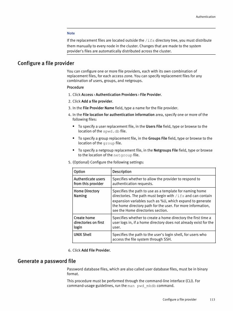
Note
If the replacement files are located outside the /ifs directory tree, you must distribute
them manually to every node in the cluster. Changes that are made to the systemprovider's files are automatically distributed across the cluster.
Configure a file providerYou can configure one or more file providers, each with its own combination ofreplacement files, for each access zone. You can specify replacement files for anycombination of users, groups, and netgroups.
Procedure
1. Click Access > Authentication Providers > File Provider.
2. Click Add a file provider.
3. In the File Provider Name field, type a name for the file provider.
4. In the File location for authentication information area, specify one or more of thefollowing files:
l To specify a user replacement file, in the Users File field, type or browse to thelocation of the spwd.db file.
l To specify a group replacement file, in the Groups File field, type or browse to thelocation of the group file.
l To specify a netgroup replacement file, in the Netgroups File field, type or browseto the location of the netgroup file.
5. (Optional) Configure the following settings:
Option Description
Authenticate usersfrom this provider
Specifies whether to allow the provider to respond toauthentication requests.
Home DirectoryNaming
Specifies the path to use as a template for naming homedirectories. The path must begin with /ifs and can containexpansion variables such as %U, which expand to generatethe home directory path for the user. For more information,see the Home directories section.
Create homedirectories on firstlogin
Specifies whether to create a home directory the first time auser logs in, if a home directory does not already exist for theuser.
UNIX Shell Specifies the path to the user's login shell, for users whoaccess the file system through SSH.
6. Click Add File Provider.
Generate a password filePassword database files, which are also called user database files, must be in binaryformat.
This procedure must be performed through the command-line interface (CLI). Forcommand-usage guidelines, run the man pwd_mkdb command.
Authentication
Configure a file provider 113
Procedure
1. Establish an SSH connection to any node in the cluster.
2. Run the pwd_mkdb <file> command, where <file> is the location of the source passwordfile.
Note
By default, the binary password file, spwd.db, is created in the /etc directory. You
can override the location to store the spwd.db file by specifying the -d option with a
different target directory.
The following command generates an spwd.db file in the /etc directory from apassword file that is located at /ifs/test.passwd:
pwd_mkdb /ifs/test.passwd
The following command generates an spwd.db file in the /ifs directory from apassword file that is located at /ifs/test.passwd:
pwd_mkdb -d /ifs /ifs/test.passwd
Password file formatThe file provider uses a binary password database file, spwd.db. You can generate abinary password file from a master.passwd-formatted file by running the pwd_mkdbcommand.
The master.passwd file contains ten colon-separated fields, as shown in the followingexample:
admin:*:10:10::0:0:Web UI Administrator:/ifs/home/admin:/bin/zsh
The fields are defined below in the order in which they appear in the file.
Note
UNIX systems often define the passwd format as a subset of these fields, omitting the
Class, Change, and Expiry fields. To convert a file from passwd to master.passwdformat, add :0:0: between the GID field and the Gecos field.
Username
The user name. This field is case-sensitive. OneFS does not limit the length; manyapplications truncate the name to 16 characters, however.
Password
The user’s encrypted password. If authentication is not required for the user, you cansubstitute an asterisk (*) for a password. The asterisk character is guaranteed to notmatch any password.
UID
The UNIX user identifier. This value must be a number in the range 0-4294967294that is not reserved or already assigned to a user. Compatibility issues occur if thisvalue conflicts with an existing account's UID.
Authentication
114 OneFS 7.2.1 Web Administration Guide

GID
The group identifier of the user’s primary group. All users are a member of at leastone group, which is used for access checks and can also be used when creatingfiles.
Class
This field is not supported by OneFS and should be left empty.
Change
OneFS does not support changing the passwords of users in the file provider. Thisfield is ignored.
Expiry
OneFS does not support the expiration of user accounts in the file provider. This fieldis ignored.
Gecos
This field can store a variety of information but is usually used to store the user’s fullname.
Home
The absolute path to the user’s home directory, beginning at /ifs.
Shell
The absolute path to the user’s shell. If this field is set to /sbin/nologin, theuser is denied command-line access.
Group file formatThe file provider uses a group file in the format of the /etc/group file that exists onmost UNIX systems.
The group file consists of one or more lines containing four colon-separated fields, asshown in the following example:
admin:*:10:root,admin
The fields are defined below in the order in which they appear in the file.
Group name
The name of the group. This field is case-sensitive. Although OneFS does not limitthe length of the group name, many applications truncate the name to 16 characters.
Password
This field is not supported by OneFS and should contain an asterisk (*).
GID
The UNIX group identifier. Valid values are any number in the range 0-4294967294that is not reserved or already assigned to a group. Compatibility issues occur if thisvalue conflicts with an existing group's GID.
Group members
A comma-delimited list of user names.
Authentication
Group file format 115
Netgroup file formatA netgroup file consists of one or more netgroups, each of which can contain members.Hosts, users, or domains, which are members of a netgroup, are specified in a membertriple. A netgroup can also contain another netgroup.
Each entry in a netgroup file consists of the netgroup name, followed by a space-delimited set of member triples and nested netgroup names. If you specify a nestednetgroup, it must be defined on a separate line in the file.A member triple takes the following form:
(<host>, <user>, <domain>)
Where <host> is a placeholder for a machine name, <user> is a placeholder for a user name,and <domain> is a placeholder for a domain name. Any combination is valid except anempty triple: (,,).
The following sample file contains two netgroups. The rootgrp netgroup contains fourhosts: two hosts are defined in member triples and two hosts are contained in the nestedothergrp netgroup, which is defined on the second line.
rootgrp (myserver, root, somedomain.com) (otherserver, root, somedomain.com) othergrpothergrp (other-win,, somedomain.com) (other-linux,, somedomain.com)
Note
A new line signifies a new netgroup. You can continue a long netgroup entry to the nextline by typing a backslash character (\) in the right-most position of the first line.
Modify a file providerYou can modify any setting for a file provider, with the exception that you cannot renamethe System file provider.
Procedure
1. Click Access > Authentication Providers > File Provider.
2. In the File Providers table, click View details for the provider whose settings you wantto modify.
3. For each setting that you want to modify, click Edit, make the change, and then clickSave.
4. Click Close.
Delete a file providerTo stop using a file provider, you can clear all of its replacement file settings or you canpermanently delete the provider.
Procedure
1. Click Access > Authentication Providers > File Provider.
2. In the File Providers table, select the provider name.
3. Select Delete from the Select an action list.
4. In the confirmation dialog box, click Delete.
Authentication
116 OneFS 7.2.1 Web Administration Guide
Managing local users and groupsWhen you create an access zone, each zone includes a local provider that allows you tocreate and manage local users and groups. Although you can view the users and groupsof any authentication provider, you can create, modify, and delete users and groups inthe local provider only.
View a list of users or groups by providerYou can view the users and groups of any authentication provider.
Procedure
1. Click Access > Membership & Roles.
2. Click one of the following, depending on what you want to view:
Option Description
Users Select this tab to view all users by provider.
Groups Select this tab to view all groups by provider.
3. From the Current Access Zone list, select an access zone.
4. Depending on your selection in step 2, select the local provider for the access zonefrom the Users list or the Groups list.
Create a local userEach access zone includes a local provider that allows you to create and manage localusers and groups. When creating a local user account, you can configure its name,password, home directory, UNIX user identifier (UID), UNIX login shell, and groupmemberships.
Procedure
1. Click Access > Membership & Roles > Users.
2. From the Current Access Zone list, select an access zone.
3. From the Users list, select the local provider for the zone.
4. Click Create a user.
5. In the Username field, type a username for the account.
6. In the Password field, type a password for the account.
7. (Optional) Configure the following additional settings as needed.
Option Description
Allow passwordto expire
Select this check box to specify that the password is allowed toexpire.
UID If this setting is left blank, the system automatically allocates aUID for the account. This is the recommended setting. You cannotassign a UID that is in use by another local user account.
Full Name Type a full name for the user.
Authentication
Managing local users and groups 117
Option Description
Email Address Type an email address for the account.
Primary Group Click Select group to specify the owner group using the Select aPrimary Group dialog box.
a. To locate a group under the selected local provider, type agroup name or click Search.
b. Select a group to return to the Manage Users window.
AdditionalGroups
Click Add group to specify any additional groups to make this usera member of.
Home Directory Type the path to the user's home directory. If you do not specify apath, a directory is automatically created at /ifs/home/<username>.
UNIX Shell This setting applies only to users who access the file systemthrough SSH. From the list, select a shell. By default,the /bin/zsh shell is selected.
AccountExpiration Date
Click the calendar icon to select the expiration date or type theexpiration date in the field, and then type the date in the format<mm>/<dd>/<yyyy>.
Enable theaccount
Select this check box to allow the user to authenticate against thelocal database for SSH, FTP, HTTP, and Windows file sharingthrough SMB. This setting is not used for UNIX file sharing throughNFS.
8. Click Create.
Create a local groupIn the local provider of an access zone, you can create groups and assign members tothem.
Procedure
1. Click Access > Membership & Roles > Groups.
2. From the Current Access Zone list, select an access zone.
3. From the Groups list, select the local provider for the zone.
4. Click Create a group.
5. In the Group Name field, type a name for the group.
6. (Optional) To override automatic allocation of the UNIX group identifier (GID), in theGID field, type a numerical value.
Note
You cannot assign a GID that is in use by another group. It is recommended that youleave this field blank to allow the system to automatically generate the GID.
7. (Optional) For each member that you want to add to the group, click Add user andperform the following tasks in the Select a User dialog box:
a. Search for either Users or Well-known SIDs.
Authentication
118 OneFS 7.2.1 Web Administration Guide
b. If you selected Users, specify values for the following fields:
UsernameType all or part of a user name, or leave the field blank to return all users.Wildcard characters are accepted.
Access ZoneSelect the access zone that contains the authentication provider that youwant to search.
ProviderSelect an authentication provider.
c. Click Search.
d. In the Search Results table, select a user and then click Select.
The dialog box closes.
8. Click Create.
Naming rules for local users and groupsLocal user and group names must follow naming rules in order to ensure properauthentication and access to the EMC Isilon cluster.
You must adhere to the following naming rules when creating and modifying local usersand groups:
l The maximum name length is 104 characters. It is recommended that names do notexceed 64 characters.
l Names cannot contain the following invalid characters:" / \ [ ] : ; | = , + * ? < >
l Names can contain any special character that is not in the list of invalid characters. Itis recommend that names do not contain spaces.
l Names are not case sensitive.
Modify a local userYou can modify any setting for a local user account except the user name.
Procedure
1. Click Access > Membership & Roles > Users.
2. From the Current Access Zone list, select an access zone.
3. From the Users list, select the local provider for the access zone.
4. In the list of users, click View details for the local user whose settings you want tomodify.
5. For each setting that you want to modify, click Edit, make the change, and then clickSave.
6. Click Close.
Modify a local groupYou can add or remove members from a local group.
Procedure
1. Click Access > Membership & Roles > Groups.
Authentication
Naming rules for local users and groups 119
2. From the Current Access Zone list, select an access zone.
3. From the Groups list, select the local provider for the access zone.
4. In the list of groups, click View details for the local group whose settings you want tomodify.
5. For the Members setting, click Edit.
6. Add or remove the users that you want, and then click Save.
7. Click Close.
Delete a local userA deleted user can no longer access the cluster through the command-line interface, webadministration interface, or file access protocol. When you delete a local user account,the corresponding home directory remains in place.
Procedure
1. Click Access > Membership & Roles > Users.
2. From the Current Access Zone list, select an access zone.
3. From the Users list, select the local provider for the access zone.
4. Click Delete for the user that you want to delete.
5. In the confirmation dialog box, click Delete.
Delete a local groupYou can delete a local group even if members are assigned to it; deleting a group doesnot affect the members of that group.
Procedure
1. Click Access > Membership & Roles > Groups.
2. From the Current Access Zone list, select an access zone.
3. From the Groups list, select the local provider for the access zone.
4. Click Delete for the group that you want to delete.
5. In the confirmation dialog box, click Delete.
Authentication
120 OneFS 7.2.1 Web Administration Guide

CHAPTER 6
Configuration access control
This section contains the following topics:
l Role-based access.............................................................................................. 122l Roles and privileges............................................................................................ 122l Managing roles................................................................................................... 134
Configuration access control 121

Role-based accessYou can assign role-based access to delegate administrative tasks to selected users.
Role based access control (RBAC) allows the right to perform particular administrativeactions to be granted to any user who can authenticate to a cluster. Roles are created bya Security Administrator, assigned privileges, and then assigned members. Alladministrators, including those given privileges by a role, must connect to the Systemzone to configure the cluster. When these members log in to the cluster through aconfiguration interface, they have these privileges. All administrators can configuresettings for access zones, and they always have control over all access zones on thecluster.
Roles also give you the ability to assign privileges to member users and groups. Bydefault, only the root user and the admin user can log in to the web administrationinterface through HTTP or the command-line interface through SSH. Using roles, the rootand admin users can assign others to built-in or customer roles that have login andadministrative privileges to perform specific administrative tasks.
Note
As a best practice, assign users to roles that contain the minimum set of necessaryprivileges. For most purposes, the default permission policy settings, system accesszone, and built-in roles are sufficient. You can create role-based access managementpolicies as necessary for your particular environment.
Roles and privilegesIn addition to controlling access to files and directories through ACLs and POSIX modebits, OneFS controls configuration-level access through administrator roles. A role is acollection of OneFS privileges that are usually associated with a configuration subsystem.Those privileges are granted to members of that role as they log in to the cluster throughthe Platform API, command-line interface, or web administration interface
RolesYou can permit and limit access to administrative areas of your EMC Isilon cluster on aper-user basis through roles.
OneFS includes built-in administrator roles with predefined sets of privileges that cannotbe modified. The following list describes what you can and cannot do through roles:
l You can assign privileges through role membership.
l You can add any user to a role as long as the user can authenticate to the cluster.
l You can create custom roles and assign privileges to those roles.
l You can add users singly or as groups, including well-known groups.
l You can assign a user as a member of more than one role.
l You can add a group to a role, which grants to all users who are members of thatgroup all of the privileges associated with the role.
l You cannot assign privileges directly to users or groups.
Configuration access control
122 OneFS 7.2.1 Web Administration Guide

Note
When OneFS is first installed, only users with root- or admin-level can log in and assignusers to roles.
Built-in rolesBuilt-in roles include privileges to perform a set of administrative functions.
The following tables describe each of the built-in roles from most powerful to leastpowerful. The tables include the privileges and read/write access levels, if applicable,that are assigned to each role. You can assign users and groups to built-in roles and toroles that you create.
Table 1 SecurityAdmin role
Description Privileges Read/writeaccess
Administer security configuration on the cluster,including authentication providers, local users andgroups, and role membership.
ISI_PRIV_LOGIN_CONSOLE N/A
ISI_PRIV_LOGIN_PAPI N/A
ISI_PRIV_LOGIN_SSH N/A
ISI_PRIV_AUTH Read/write
ISI_PRIV_ROLE Read/write
Table 2 SystemAdmin role
Description Privileges Read/writeaccess
Administer all aspects of cluster configuration thatare not specifically handled by the SecurityAdminrole.
ISI_PRIV_LOGIN_CONSOLE N/A
ISI_PRIV_LOGIN_PAPI N/A
ISI_PRIV_LOGIN_SSH N/A
ISI_PRIV_SYS_SHUTDOWN N/A
ISI_PRIV_SYS_SUPPORT N/A
ISI_PRIV_SYS_TIME N/A
ISI_PRIV_ANTIVIRUS Read/write
ISI_PRIV_AUDIT Read/write
ISI_PRIV_CLUSTER Read/write
ISI_PRIV_DEVICES Read/write
ISI_PRIV_EVENT Read/write
ISI_PRIV_FTP Read/write
ISI_PRIV_HDFS Read/write
ISI_PRIV_HTTP Read/write
ISI_PRIV_ISCSI Read/write
ISI_PRIV_JOB_ENGINE Read/write
Configuration access control
Roles 123
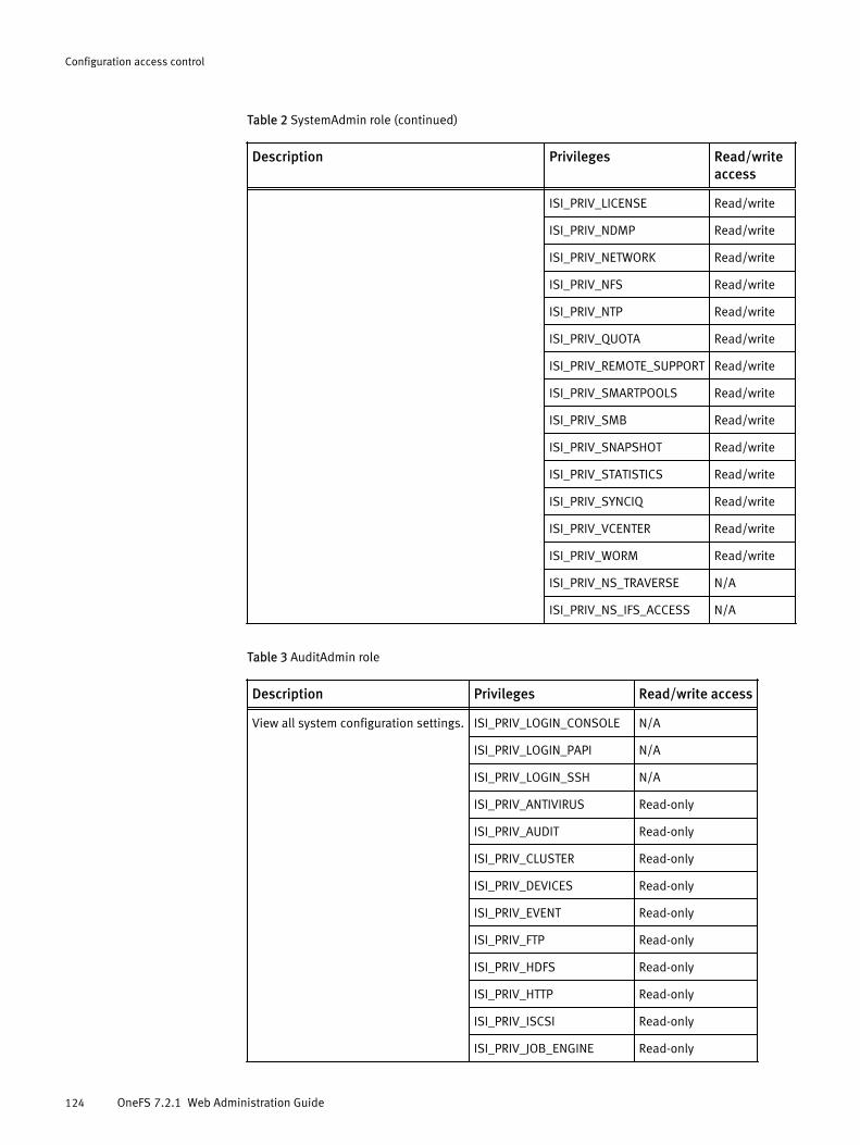
Table 2 SystemAdmin role (continued)
Description Privileges Read/writeaccess
ISI_PRIV_LICENSE Read/write
ISI_PRIV_NDMP Read/write
ISI_PRIV_NETWORK Read/write
ISI_PRIV_NFS Read/write
ISI_PRIV_NTP Read/write
ISI_PRIV_QUOTA Read/write
ISI_PRIV_REMOTE_SUPPORT Read/write
ISI_PRIV_SMARTPOOLS Read/write
ISI_PRIV_SMB Read/write
ISI_PRIV_SNAPSHOT Read/write
ISI_PRIV_STATISTICS Read/write
ISI_PRIV_SYNCIQ Read/write
ISI_PRIV_VCENTER Read/write
ISI_PRIV_WORM Read/write
ISI_PRIV_NS_TRAVERSE N/A
ISI_PRIV_NS_IFS_ACCESS N/A
Table 3 AuditAdmin role
Description Privileges Read/write access
View all system configuration settings. ISI_PRIV_LOGIN_CONSOLE N/A
ISI_PRIV_LOGIN_PAPI N/A
ISI_PRIV_LOGIN_SSH N/A
ISI_PRIV_ANTIVIRUS Read-only
ISI_PRIV_AUDIT Read-only
ISI_PRIV_CLUSTER Read-only
ISI_PRIV_DEVICES Read-only
ISI_PRIV_EVENT Read-only
ISI_PRIV_FTP Read-only
ISI_PRIV_HDFS Read-only
ISI_PRIV_HTTP Read-only
ISI_PRIV_ISCSI Read-only
ISI_PRIV_JOB_ENGINE Read-only
Configuration access control
124 OneFS 7.2.1 Web Administration Guide
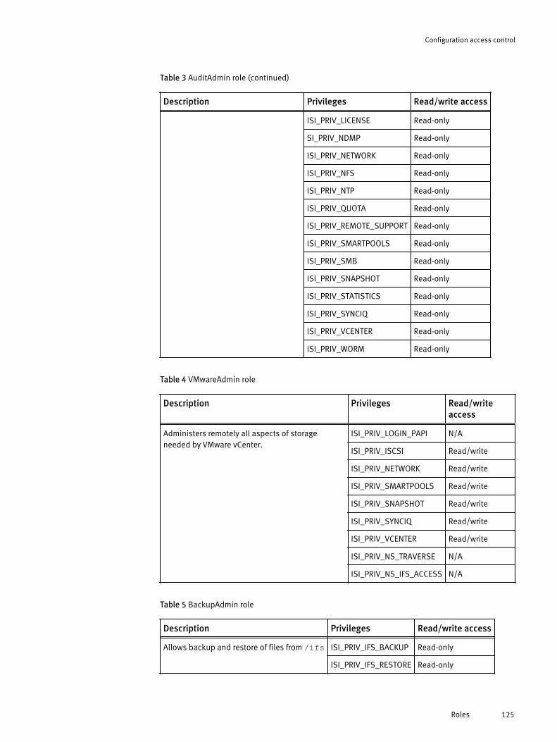
Table 3 AuditAdmin role (continued)
Description Privileges Read/write access
ISI_PRIV_LICENSE Read-only
SI_PRIV_NDMP Read-only
ISI_PRIV_NETWORK Read-only
ISI_PRIV_NFS Read-only
ISI_PRIV_NTP Read-only
ISI_PRIV_QUOTA Read-only
ISI_PRIV_REMOTE_SUPPORT Read-only
ISI_PRIV_SMARTPOOLS Read-only
ISI_PRIV_SMB Read-only
ISI_PRIV_SNAPSHOT Read-only
ISI_PRIV_STATISTICS Read-only
ISI_PRIV_SYNCIQ Read-only
ISI_PRIV_VCENTER Read-only
ISI_PRIV_WORM Read-only
Table 4 VMwareAdmin role
Description Privileges Read/writeaccess
Administers remotely all aspects of storageneeded by VMware vCenter.
ISI_PRIV_LOGIN_PAPI N/A
ISI_PRIV_ISCSI Read/write
ISI_PRIV_NETWORK Read/write
ISI_PRIV_SMARTPOOLS Read/write
ISI_PRIV_SNAPSHOT Read/write
ISI_PRIV_SYNCIQ Read/write
ISI_PRIV_VCENTER Read/write
ISI_PRIV_NS_TRAVERSE N/A
ISI_PRIV_NS_IFS_ACCESS N/A
Table 5 BackupAdmin role
Description Privileges Read/write access
Allows backup and restore of files from /ifs ISI_PRIV_IFS_BACKUP Read-only
ISI_PRIV_IFS_RESTORE Read-only
Configuration access control
Roles 125
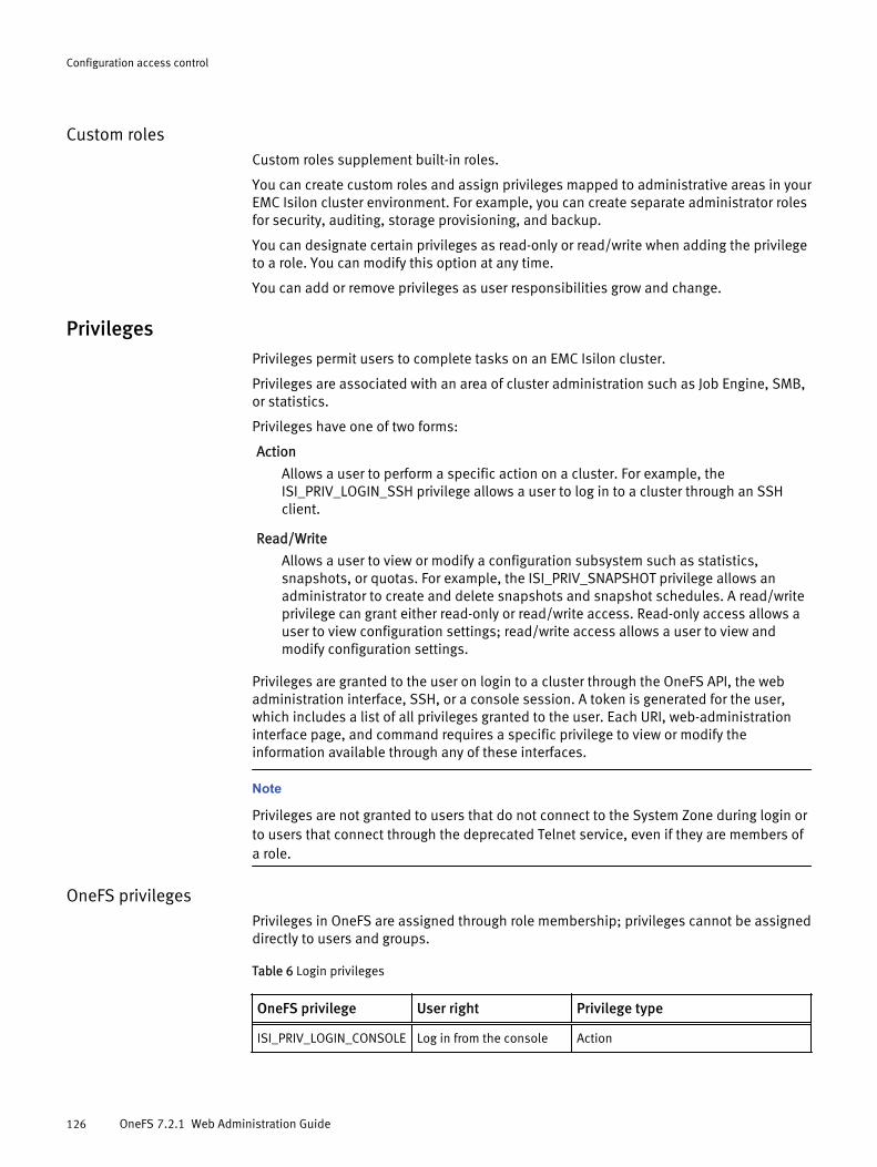
Custom rolesCustom roles supplement built-in roles.
You can create custom roles and assign privileges mapped to administrative areas in yourEMC Isilon cluster environment. For example, you can create separate administrator rolesfor security, auditing, storage provisioning, and backup.
You can designate certain privileges as read-only or read/write when adding the privilegeto a role. You can modify this option at any time.
You can add or remove privileges as user responsibilities grow and change.
PrivilegesPrivileges permit users to complete tasks on an EMC Isilon cluster.
Privileges are associated with an area of cluster administration such as Job Engine, SMB,or statistics.
Privileges have one of two forms:
Action
Allows a user to perform a specific action on a cluster. For example, theISI_PRIV_LOGIN_SSH privilege allows a user to log in to a cluster through an SSHclient.
Read/Write
Allows a user to view or modify a configuration subsystem such as statistics,snapshots, or quotas. For example, the ISI_PRIV_SNAPSHOT privilege allows anadministrator to create and delete snapshots and snapshot schedules. A read/writeprivilege can grant either read-only or read/write access. Read-only access allows auser to view configuration settings; read/write access allows a user to view andmodify configuration settings.
Privileges are granted to the user on login to a cluster through the OneFS API, the webadministration interface, SSH, or a console session. A token is generated for the user,which includes a list of all privileges granted to the user. Each URI, web-administrationinterface page, and command requires a specific privilege to view or modify theinformation available through any of these interfaces.
Note
Privileges are not granted to users that do not connect to the System Zone during login orto users that connect through the deprecated Telnet service, even if they are members ofa role.
OneFS privilegesPrivileges in OneFS are assigned through role membership; privileges cannot be assigneddirectly to users and groups.
Table 6 Login privileges
OneFS privilege User right Privilege type
ISI_PRIV_LOGIN_CONSOLE Log in from the console Action
Configuration access control
126 OneFS 7.2.1 Web Administration Guide
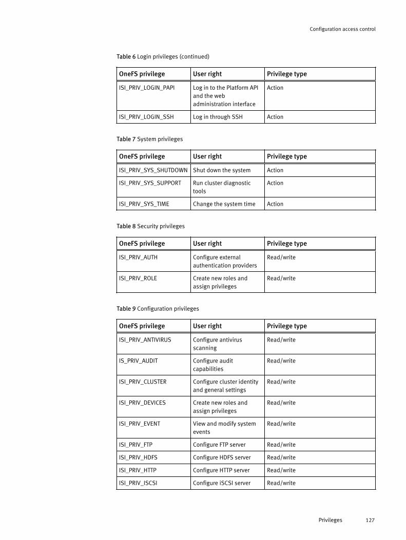
Table 6 Login privileges (continued)
OneFS privilege User right Privilege type
ISI_PRIV_LOGIN_PAPI Log in to the Platform APIand the webadministration interface
Action
ISI_PRIV_LOGIN_SSH Log in through SSH Action
Table 7 System privileges
OneFS privilege User right Privilege type
ISI_PRIV_SYS_SHUTDOWN Shut down the system Action
ISI_PRIV_SYS_SUPPORT Run cluster diagnostictools
Action
ISI_PRIV_SYS_TIME Change the system time Action
Table 8 Security privileges
OneFS privilege User right Privilege type
ISI_PRIV_AUTH Configure externalauthentication providers
Read/write
ISI_PRIV_ROLE Create new roles andassign privileges
Read/write
Table 9 Configuration privileges
OneFS privilege User right Privilege type
ISI_PRIV_ANTIVIRUS Configure antivirusscanning
Read/write
IS_PRIV_AUDIT Configure auditcapabilities
Read/write
ISI_PRIV_CLUSTER Configure cluster identityand general settings
Read/write
ISI_PRIV_DEVICES Create new roles andassign privileges
Read/write
ISI_PRIV_EVENT View and modify systemevents
Read/write
ISI_PRIV_FTP Configure FTP server Read/write
ISI_PRIV_HDFS Configure HDFS server Read/write
ISI_PRIV_HTTP Configure HTTP server Read/write
ISI_PRIV_ISCSI Configure iSCSI server Read/write
Configuration access control
Privileges 127
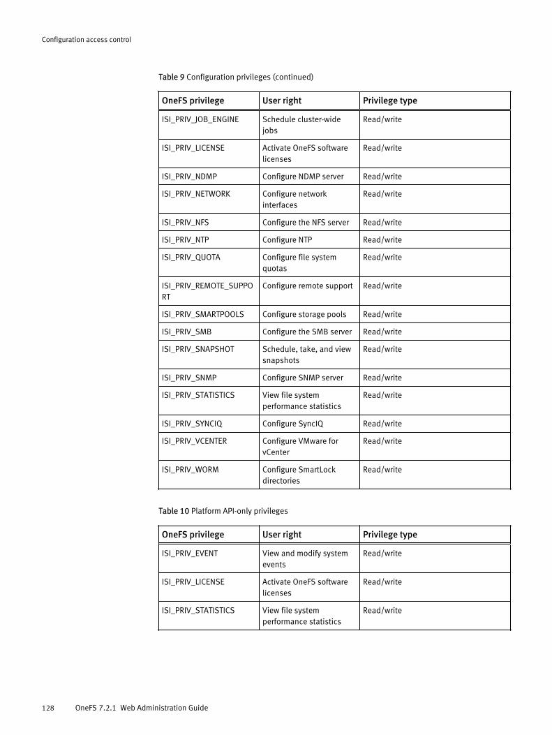
Table 9 Configuration privileges (continued)
OneFS privilege User right Privilege type
ISI_PRIV_JOB_ENGINE Schedule cluster-widejobs
Read/write
ISI_PRIV_LICENSE Activate OneFS softwarelicenses
Read/write
ISI_PRIV_NDMP Configure NDMP server Read/write
ISI_PRIV_NETWORK Configure networkinterfaces
Read/write
ISI_PRIV_NFS Configure the NFS server Read/write
ISI_PRIV_NTP Configure NTP Read/write
ISI_PRIV_QUOTA Configure file systemquotas
Read/write
ISI_PRIV_REMOTE_SUPPORT
Configure remote support Read/write
ISI_PRIV_SMARTPOOLS Configure storage pools Read/write
ISI_PRIV_SMB Configure the SMB server Read/write
ISI_PRIV_SNAPSHOT Schedule, take, and viewsnapshots
Read/write
ISI_PRIV_SNMP Configure SNMP server Read/write
ISI_PRIV_STATISTICS View file systemperformance statistics
Read/write
ISI_PRIV_SYNCIQ Configure SyncIQ Read/write
ISI_PRIV_VCENTER Configure VMware forvCenter
Read/write
ISI_PRIV_WORM Configure SmartLockdirectories
Read/write
Table 10 Platform API-only privileges
OneFS privilege User right Privilege type
ISI_PRIV_EVENT View and modify systemevents
Read/write
ISI_PRIV_LICENSE Activate OneFS softwarelicenses
Read/write
ISI_PRIV_STATISTICS View file systemperformance statistics
Read/write
Configuration access control
128 OneFS 7.2.1 Web Administration Guide
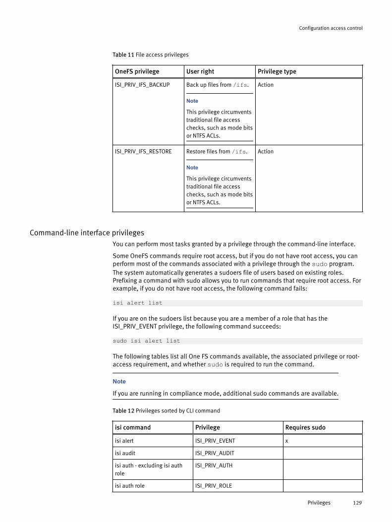
Table 11 File access privileges
OneFS privilege User right Privilege type
ISI_PRIV_IFS_BACKUP Back up files from /ifs.
Note
This privilege circumventstraditional file accesschecks, such as mode bitsor NTFS ACLs.
Action
ISI_PRIV_IFS_RESTORE Restore files from /ifs.
Note
This privilege circumventstraditional file accesschecks, such as mode bitsor NTFS ACLs.
Action
Command-line interface privilegesYou can perform most tasks granted by a privilege through the command-line interface.
Some OneFS commands require root access, but if you do not have root access, you canperform most of the commands associated with a privilege through the sudo program.The system automatically generates a sudoers file of users based on existing roles.Prefixing a command with sudo allows you to run commands that require root access. Forexample, if you do not have root access, the following command fails:
isi alert list
If you are on the sudoers list because you are a member of a role that has theISI_PRIV_EVENT privilege, the following command succeeds:
sudo isi alert list
The following tables list all One FS commands available, the associated privilege or root-access requirement, and whether sudo is required to run the command.
Note
If you are running in compliance mode, additional sudo commands are available.
Table 12 Privileges sorted by CLI command
isi command Privilege Requires sudo
isi alert ISI_PRIV_EVENT x
isi audit ISI_PRIV_AUDIT
isi auth - excluding isi authrole
ISI_PRIV_AUTH
isi auth role ISI_PRIV_ROLE
Configuration access control
Privileges 129
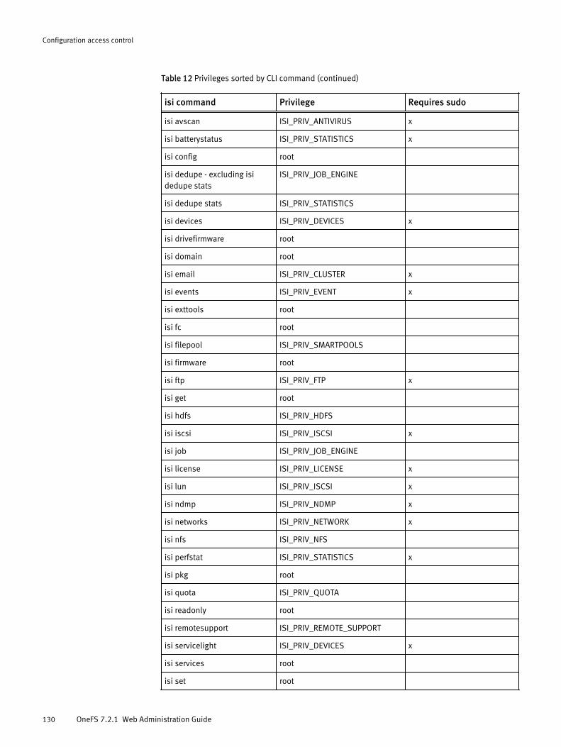
Table 12 Privileges sorted by CLI command (continued)
isi command Privilege Requires sudo
isi avscan ISI_PRIV_ANTIVIRUS x
isi batterystatus ISI_PRIV_STATISTICS x
isi config root
isi dedupe - excluding isidedupe stats
ISI_PRIV_JOB_ENGINE
isi dedupe stats ISI_PRIV_STATISTICS
isi devices ISI_PRIV_DEVICES x
isi drivefirmware root
isi domain root
isi email ISI_PRIV_CLUSTER x
isi events ISI_PRIV_EVENT x
isi exttools root
isi fc root
isi filepool ISI_PRIV_SMARTPOOLS
isi firmware root
isi ftp ISI_PRIV_FTP x
isi get root
isi hdfs ISI_PRIV_HDFS
isi iscsi ISI_PRIV_ISCSI x
isi job ISI_PRIV_JOB_ENGINE
isi license ISI_PRIV_LICENSE x
isi lun ISI_PRIV_ISCSI x
isi ndmp ISI_PRIV_NDMP x
isi networks ISI_PRIV_NETWORK x
isi nfs ISI_PRIV_NFS
isi perfstat ISI_PRIV_STATISTICS x
isi pkg root
isi quota ISI_PRIV_QUOTA
isi readonly root
isi remotesupport ISI_PRIV_REMOTE_SUPPORT
isi servicelight ISI_PRIV_DEVICES x
isi services root
isi set root
Configuration access control
130 OneFS 7.2.1 Web Administration Guide
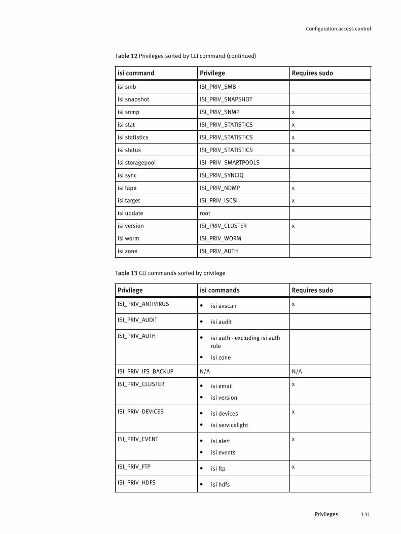
Table 12 Privileges sorted by CLI command (continued)
isi command Privilege Requires sudo
isi smb ISI_PRIV_SMB
isi snapshot ISI_PRIV_SNAPSHOT
isi snmp ISI_PRIV_SNMP x
isi stat ISI_PRIV_STATISTICS x
isi statistics ISI_PRIV_STATISTICS x
isi status ISI_PRIV_STATISTICS x
isi storagepool ISI_PRIV_SMARTPOOLS
isi sync ISI_PRIV_SYNCIQ
isi tape ISI_PRIV_NDMP x
isi target ISI_PRIV_ISCSI x
isi update root
isi version ISI_PRIV_CLUSTER x
isi worm ISI_PRIV_WORM
isi zone ISI_PRIV_AUTH
Table 13 CLI commands sorted by privilege
Privilege isi commands Requires sudo
ISI_PRIV_ANTIVIRUS l isi avscan x
ISI_PRIV_AUDIT l isi audit
ISI_PRIV_AUTH l isi auth - excluding isi authrole
l isi zone
ISI_PRIV_IFS_BACKUP N/A N/A
ISI_PRIV_CLUSTER l isi email
l isi version
x
ISI_PRIV_DEVICES l isi devices
l isi servicelight
x
ISI_PRIV_EVENT l isi alert
l isi events
x
ISI_PRIV_FTP l isi ftp x
ISI_PRIV_HDFS l isi hdfs
Configuration access control
Privileges 131
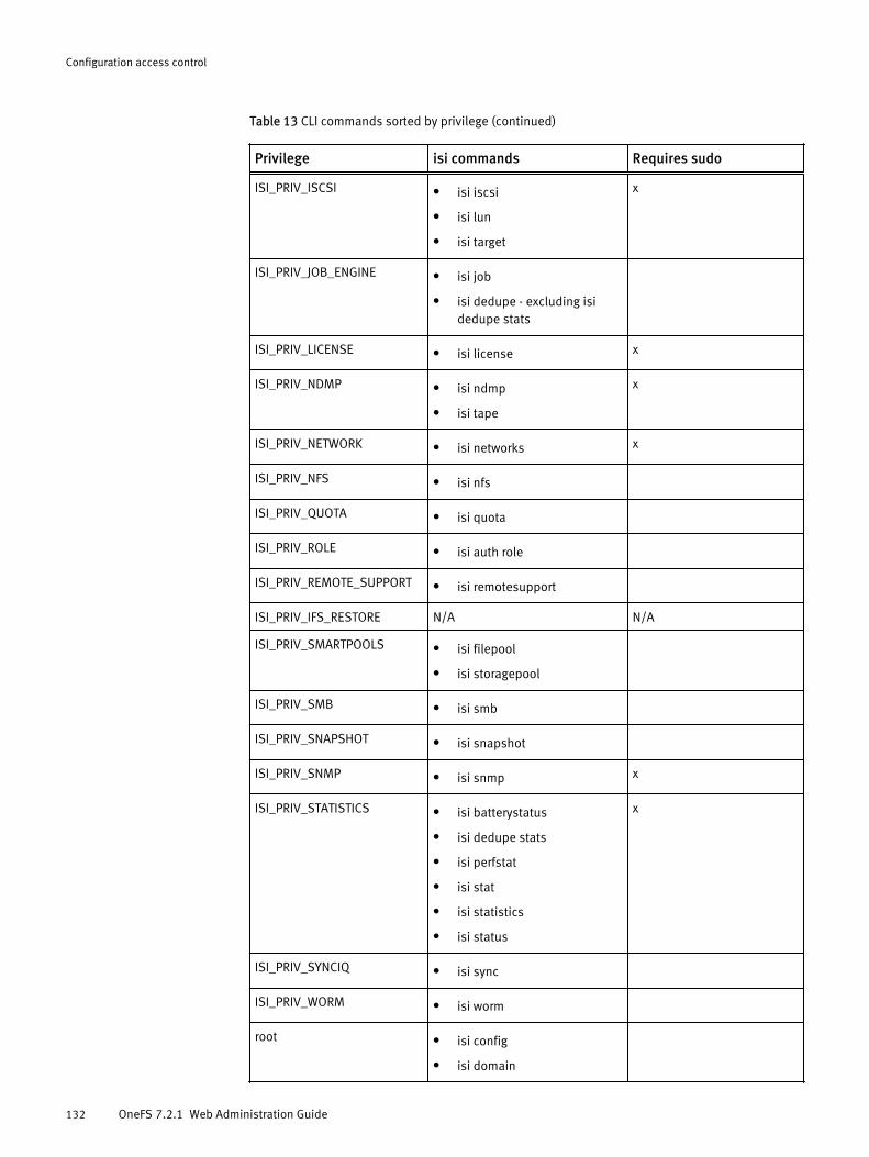
Table 13 CLI commands sorted by privilege (continued)
Privilege isi commands Requires sudo
ISI_PRIV_ISCSI l isi iscsi
l isi lun
l isi target
x
ISI_PRIV_JOB_ENGINE l isi job
l isi dedupe - excluding isidedupe stats
ISI_PRIV_LICENSE l isi license x
ISI_PRIV_NDMP l isi ndmp
l isi tape
x
ISI_PRIV_NETWORK l isi networks x
ISI_PRIV_NFS l isi nfs
ISI_PRIV_QUOTA l isi quota
ISI_PRIV_ROLE l isi auth role
ISI_PRIV_REMOTE_SUPPORT l isi remotesupport
ISI_PRIV_IFS_RESTORE N/A N/A
ISI_PRIV_SMARTPOOLS l isi filepool
l isi storagepool
ISI_PRIV_SMB l isi smb
ISI_PRIV_SNAPSHOT l isi snapshot
ISI_PRIV_SNMP l isi snmp x
ISI_PRIV_STATISTICS l isi batterystatus
l isi dedupe stats
l isi perfstat
l isi stat
l isi statistics
l isi status
x
ISI_PRIV_SYNCIQ l isi sync
ISI_PRIV_WORM l isi worm
root l isi config
l isi domain
Configuration access control
132 OneFS 7.2.1 Web Administration Guide
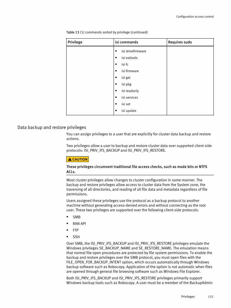
Table 13 CLI commands sorted by privilege (continued)
Privilege isi commands Requires sudo
l isi drivefirmware
l isi exttools
l isi fc
l isi firmware
l isi get
l isi pkg
l isi readonly
l isi services
l isi set
l isi update
Data backup and restore privilegesYou can assign privileges to a user that are explicitly for cluster data backup and restoreactions.
Two privileges allow a user to backup and restore cluster data over supported client-sideprotocols: ISI_PRIV_IFS_BACKUP and ISI_PRIV_IFS_RESTORE.
CAUTION
These privileges circumvent traditional file access checks, such as mode bits or NTFSACLs.
Most cluster privileges allow changes to cluster configuration in some manner. Thebackup and restore privileges allow access to cluster data from the System zone, thetraversing of all directories, and reading of all file data and metadata regardless of filepermissions.
Users assigned these privileges use the protocol as a backup protocol to anothermachine without generating access-denied errors and without connecting as the rootuser. These two privileges are supported over the following client-side protocols:
l SMB
l RAN API
l FTP
l SSH
Over SMB, the ISI_PRIV_IFS_BACKUP and ISI_PRIV_IFS_RESTORE privileges emulate theWindows privileges SE_BACKUP_NAME and SE_RESTORE_NAME. The emulation meansthat normal file-open procedures are protected by file system permissions. To enable thebackup and restore privileges over the SMB protocol, you must open files with theFILE_OPEN_FOR_BACKUP_INTENT option, which occurs automatically through Windowsbackup software such as Robocopy. Application of the option is not automatic when filesare opened through general file browsing software such as Windows File Explorer.
Both ISI_PRIV_IFS_BACKUP and ISI_PRIV_IFS_RESTORE privileges primarily supportWindows backup tools such as Robocopy. A user must be a member of the BackupAdmin
Configuration access control
Privileges 133
built-in role to access all Robocopy features, which includes copying file DACL and SACLmetadata.
Managing rolesYou can view, add, or remove members of any role. Except for built-in roles, whoseprivileges you cannot modify, you can add or remove OneFS privileges on a role-by-rolebasis.
Note
Roles take both users and groups as members. If a group is added to a role, all users whoare members of that group are assigned the privileges associated with the role. Similarly,members of multiple roles are assigned the combined privileges of each role.
Create a custom roleYou can create a custom role and add privileges and members to that role.
Procedure
1. Click Access > Membership & Roles > Roles.
2. Click Create a Role.
3. In the Role Name field, type a name for the role.
4. In the Description field, type a description.
5. Click Add a member to this role to add a member to the role.
6. Click Add a privilege to this role to assign access rights and privileges.
7. Click Create Role.
Modify a roleYou can modify the description and the user or group membership of any role, includingbuilt-in roles. However, you can modify the name and privileges only for custom roles.
Procedure
1. Click Access > Membership & Roles > Roles.
2. In the Roles area, select a role and click View / Edit.
The View Role Details dialog box appears.
3. Click Edit Role and modify the settings as needed in the Edit Role Details dialog box.
4. Click Save Changes to return to the View Role Details dialog box.
5. Click Close.
Copy a roleYou can copy an existing role and add or remove privileges and members for that role asneeded.
Procedure
1. Click Access > Membership & Roles > Roles.
2. In the Roles area, select a role and click More > Copy.
3. Modify the role name, description, members, and privileges as needed.
Configuration access control
134 OneFS 7.2.1 Web Administration Guide
4. Click Copy Role.
Add a privilege to a custom roleYou can add or remove privileges to a custom role as needed. You can designate certainprivileges as read-only or read/write. You cannot modify the privileges assigned to abuilt-in role. Repeat this procedure for each privilege that you want to add to a customrole.
Procedure
1. Click Add a privilege to this role in the dialog box for creating, copying, or editing arole.
2. In the Add a privilege to this role dialog box, select an access type for the role.
3. Select a privilege from the list.
4. Click Add Privilege.
Add a member to a roleYou can add one or more members to a role when creating, copying, or modifying therole. A user or a group can be a member of more than one role. The privileges associatedwith a role are granted to all members of that role. Repeat this procedure to add moremembers to the role.
Procedure
1. Click Add a member to this role in the dialog box for creating, copying, or editing arole.
2. In the Select a User dialog box, select one of following options:
l Users
l Groups
l Well-known SIDs
3. If you selected User or Group, locate the user or group through one of the followingmethods:
l Type the Username or Group Name you want to search for in the text field.
l Select the authentication provider you want to search for from the Provider list.Only providers that are currently configured and enabled on the cluster are listed.
4. Click Search.
5. Select a user name, group name, or a well-known SID from the search results to addas members to the role.
6. Click Select.
Delete a custom roleDeleting a custom role does not affect the privileges or users that are assigned to it. Youcannot delete built-in roles.
Procedure
1. Click Access > Membership & Roles > Roles.
2. In the Roles area, select one or more roles, and then perform one of the followingactions:
Configuration access control
Add a privilege to a custom role 135

l To delete a single role, click More > Delete from the Actions column against theselected role.
l To delete multiple roles, select Delete Selection from the Select a bulk action list.
3. In the confirmation dialog box, click Delete.
View a roleYou can view information about built-in and custom roles.
Procedure
1. Click Access > Membership & Roles > Roles.
2. In the Roles area, select a role and click View / Edit.
3. In the View Role Details dialog box, view information about the role.
4. Click Close to return to the Membership & Roles page.
View privilegesYou can view user privileges.
This procedure must be performed through the command-line interface (CLI). You canview a list of your privileges or the privileges of another user using the followingcommands:
Procedure
1. Establish an SSH connection to any node in the cluster.
2. To view privileges, run one of the following commands.
l To view a list of all privileges, run the following command:
isi auth privileges --verbosel To view a list of your privileges, run the following command:
isi auth idl To view a list of privileges for another user, run the following command, where
<user> is a placeholder for another user by name:
isi auth mapping token <user>
Configuration access control
136 OneFS 7.2.1 Web Administration Guide
CHAPTER 7
Identity management
This section contains the following topics:
l Identity management overview............................................................................138l Identity types...................................................................................................... 138l Access tokens..................................................................................................... 139l Access token generation..................................................................................... 140l Managing ID mappings........................................................................................145l Managing user identities.....................................................................................148
Identity management 137
Identity management overviewIn environments with several different types of directory services, OneFS maps the usersand groups from the separate services to provide a single unified identity on an EMCIsilon cluster and uniform access control to files and directories, regardless of theincoming protocol. This process is called identity mapping.
Isilon clusters are frequently deployed in multiprotocol environments with multiple typesof directory services, such as Active Directory and LDAP. When a user with accounts inmultiple directory services logs in to a cluster, OneFS combines the user’s identities andprivileges from all the directory services into a native access token.
You can configure OneFS settings to include a list of rules for access token manipulationto control user identity and privileges. For example, you can set a user mapping rule tomerge an Active Directory identity and an LDAP identity into a single token that works foraccess to files stored over both SMB and NFS. The token can include groups from ActiveDirectory and LDAP. The mapping rules that you create can solve identity problems bymanipulating access tokens in many ways, including the following examples:
l Authenticate a user with Active Directory but give the user a UNIX identity.
l Select a primary group from competing choices in Active Directory or LDAP.
l Disallow login of users that do not exist in both Active Directory and LDAP.
For more information about identity management, see the white paper Managing identitieswith the Isilon OneFS user mapping service at EMC Online Support.
Identity typesOneFS supports three primary identity types, each of which you can store directly on thefile system. Identity types are user identifier and group identifier for UNIX, and securityidentifier for Windows.
When you log on to an EMC Isilon cluster, the user mapper expands your identity toinclude your other identities from all the directory services, including Active Directory,LDAP, and NIS. After OneFS maps your identities across the directory services, itgenerates an access token that includes the identity information associated with youraccounts. A token includes the following identifiers:
l A UNIX user identifier (UID) and a group identifier (GID). A UID or GID is a 32-bitnumber with a maximum value of 4,294,967,295.
l A security identifier (SID) for a Windows user account. A SID is a series of authoritiesand sub-authorities ending with a 32-bit relative identifier (RID). Most SIDs have theform S-1-5-21-<A>-<B>-<C>-<RID>, where <A>, <B>, and <C> are specific to a domain orcomputer and <RID> denotes the object in the domain.
l A primary group SID for a Windows group account.
l A list of supplemental identities, including all groups in which the user is a member.
The token also contains privileges that stem from administrative role-based accesscontrol.
On an Isilon cluster, a file contains permissions, which appear as an access control list(ACL). The ACL controls access to directories, files, and other securable system objects.
When a user tries to access a file, OneFS compares the identities in the user’s accesstoken with the file’s ACL. OneFS grants access when the file’s ACL includes an accesscontrol entry (ACE) that allows the identity in the token to access the file and that does
Identity management
138 OneFS 7.2.1 Web Administration Guide
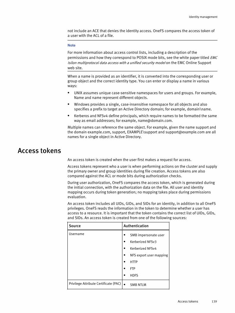
not include an ACE that denies the identity access. OneFS compares the access token ofa user with the ACL of a file.
Note
For more information about access control lists, including a description of thepermissions and how they correspond to POSIX mode bits, see the white paper titled EMCIsilon multiprotocol data access with a unified security model on the EMC Online Supportweb site.
When a name is provided as an identifier, it is converted into the corresponding user orgroup object and the correct identity type. You can enter or display a name in variousways:
l UNIX assumes unique case-sensitive namespaces for users and groups. For example,Name and name represent different objects.
l Windows provides a single, case-insensitive namespace for all objects and alsospecifies a prefix to target an Active Directory domain; for example, domain\name.
l Kerberos and NFSv4 define principals, which require names to be formatted the sameway as email addresses; for example, [email protected].
Multiple names can reference the same object. For example, given the name support andthe domain example.com, support, EXAMPLE\support and [email protected] are allnames for a single object in Active Directory.
Access tokensAn access token is created when the user first makes a request for access.
Access tokens represent who a user is when performing actions on the cluster and supplythe primary owner and group identities during file creation. Access tokens are alsocompared against the ACL or mode bits during authorization checks.
During user authorization, OneFS compares the access token, which is generated duringthe initial connection, with the authorization data on the file. All user and identitymapping occurs during token generation; no mapping takes place during permissionsevaluation.
An access token includes all UIDs, GIDs, and SIDs for an identity, in addition to all OneFSprivileges. OneFS reads the information in the token to determine whether a user hasaccess to a resource. It is important that the token contains the correct list of UIDs, GIDs,and SIDs. An access token is created from one of the following sources:
Source Authentication
Username l SMB impersonate user
l Kerberized NFSv3
l Kerberized NFSv4
l NFS export user mapping
l HTTP
l FTP
l HDFS
Privilege Attribute Certificate (PAC) l SMB NTLM
Identity management
Access tokens 139
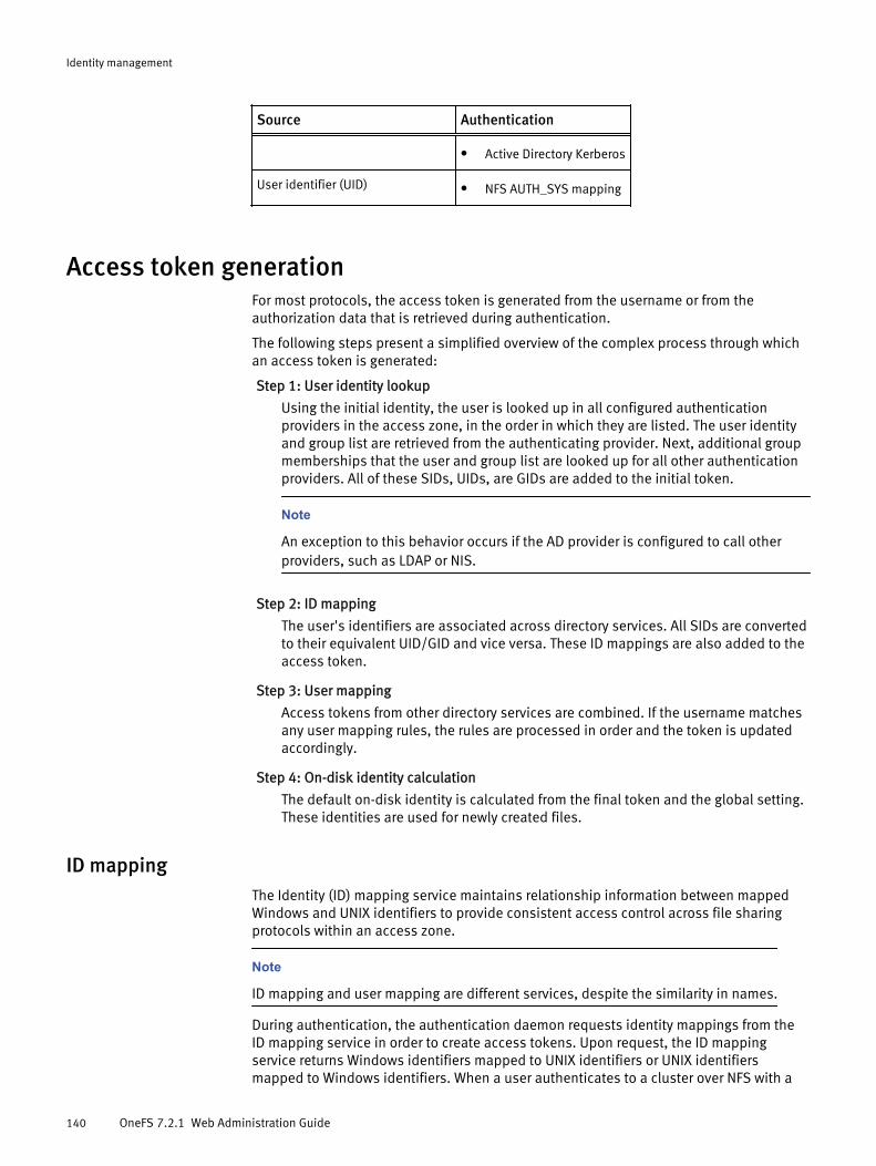
Source Authentication
l Active Directory Kerberos
User identifier (UID) l NFS AUTH_SYS mapping
Access token generationFor most protocols, the access token is generated from the username or from theauthorization data that is retrieved during authentication.
The following steps present a simplified overview of the complex process through whichan access token is generated:
Step 1: User identity lookup
Using the initial identity, the user is looked up in all configured authenticationproviders in the access zone, in the order in which they are listed. The user identityand group list are retrieved from the authenticating provider. Next, additional groupmemberships that the user and group list are looked up for all other authenticationproviders. All of these SIDs, UIDs, are GIDs are added to the initial token.
Note
An exception to this behavior occurs if the AD provider is configured to call otherproviders, such as LDAP or NIS.
Step 2: ID mapping
The user's identifiers are associated across directory services. All SIDs are convertedto their equivalent UID/GID and vice versa. These ID mappings are also added to theaccess token.
Step 3: User mapping
Access tokens from other directory services are combined. If the username matchesany user mapping rules, the rules are processed in order and the token is updatedaccordingly.
Step 4: On-disk identity calculation
The default on-disk identity is calculated from the final token and the global setting.These identities are used for newly created files.
ID mappingThe Identity (ID) mapping service maintains relationship information between mappedWindows and UNIX identifiers to provide consistent access control across file sharingprotocols within an access zone.
Note
ID mapping and user mapping are different services, despite the similarity in names.
During authentication, the authentication daemon requests identity mappings from theID mapping service in order to create access tokens. Upon request, the ID mappingservice returns Windows identifiers mapped to UNIX identifiers or UNIX identifiersmapped to Windows identifiers. When a user authenticates to a cluster over NFS with a
Identity management
140 OneFS 7.2.1 Web Administration Guide
UID or GID, the ID mapping service returns the mapped Windows SID, allowing access tofiles that another user stored over SMB. When a user authenticates to the cluster overSMB with a SID, the ID mapping service returns the mapped UNIX UID and GID, allowingaccess to files that a UNIX client stored over NFS.
Mappings between UIDs or GIDs and SIDs are stored according to access zone in acluster-distributed database called the ID map. Each mapping in the ID map is stored as aone-way relationship from the source to the target identity type. Two-way mappings arestored as complementary one-way mappings.
Mapping Windows IDs to UNIX IDsWhen a Windows user authenticates with an SID, the authentication daemon searchesthe external Active Directory provider to look up the user or group associated with theSID. If the user or group has only an SID in the Active Directory, the authenticationdaemon requests a mapping from the ID mapping service.
Note
User and group lookups may be disabled or limited, depending on the Active Directorysettings. You enable user and group lookup settings through the isi auth adsmodify command.
If the ID mapping service does not locate and return a mapped UID or GID in the ID map,the authentication daemon searches other external authentication providers configuredin the same access zone for a user that matches the same name as the Active Directoryuser.
If a matching user name is found in another external provider, the authentication daemonadds the matching user's UID or GID to the access token for the Active Directory user, andthe ID mapping service creates a mapping between the UID or GID and the ActiveDirectory user's SID in the ID map. This is referred to as an external mapping.
Note
When an external mapping is stored in the ID map, the UID is specified as the on-diskidentity for that user. When the ID mapping service stores a generated mapping, the SIDis specified as the on-disk identity.
If a matching user name is not found in another external provider, the authenticationdaemon assigns a UID or GID from the ID mapping range to the Active Directory user'sSID, and the ID mapping service stores the mapping in the ID map. This is referred to as agenerated mapping. The ID mapping range is a pool of UIDs and GIDs allocated in themapping settings.
After a mapping has been created for a user, the authentication daemon retrieves the UIDor GID stored in the ID map upon subsequent lookups for the user.
Mapping UNIX IDs to Windows IDsThe ID mapping service creates temporary UID-to-SID and GID-to-SID mappings only if amapping does not already exist. The UNIX SIDs that result from these mappings are neverstored on disk.
UIDs and GIDs have a set of predefined mappings to and from SIDs.
If a UID-to-SID or GID-to-SID mapping is requested during authentication, the ID mappingservice generates a temporary UNIX SID in the format S-1-22-1-<UID> or S-1-22-2-<GID> byapplying the following rules:
Identity management
ID mapping 141

l For UIDs, the ID mapping service generates a UNIX SID with a domain of S-1-22-1 anda resource ID (RID) matching the UID. For example, the UNIX SID for UID 600 isS-1-22-1-600.
l For GIDs, the ID mapping service generates a UNIX SID with a domain of S-1-22-2 andan RID matching the GID. For example, the UNIX SID for GID 800 is S-1-22-2-800.
ID mapping rangesIn access zones with multiple external authentication providers, such as Active Directoryand LDAP, it is important that the UIDs and GIDs from different providers that areconfigured in the same access zone do not overlap. Overlapping UIDs and GIDs betweenproviders within an access zone might result in some users gaining access to other users'directories and files.
The range of UIDs and GIDs that can be allocated for generated mappings is configurablein each access zone through the isi auth settings mappings modifycommand. The default range for both UIDs and GIDs is 1000000–2000000 in eachaccess zone.
Do not include commonly used UIDs and GIDs in your ID ranges. For example, UIDs andGIDs below 1000 are reserved for system accounts and should not be assigned to usersor groups.
User mappingUser mapping provides a way to control permissions by specifying a user's securityidentifiers, user identifiers, and group identifiers. OneFS uses the identifiers to check fileor group ownership.
With the user-mapping feature, you can apply rules to modify which user identity OneFSuses, add supplemental user identities, and modify a user's group membership. Theuser-mapping service combines a user’s identities from different directory services into asingle access token and then modifies it according to the rules that you create.
Note
You can configure mapping rules on a per-zone basis. Mapping rules must be configuredseparately in each access zone that uses them. OneFS maps users only during login orprotocol access.
Default user mappingsDefault user mappings determine access if explicit user-mapping rules are not created.
If you do not configure rules, a user who authenticates with one directory service receivesthe identity information in other directory services when the account names are the same.For example, a user who authenticates with an Active Directory domain as Desktop\janeautomatically receives identities in the final access token for the corresponding UNIX useraccount for jane from LDAP or NIS.
In the most common scenario, OneFS is connected to two directory services, ActiveDirectory and LDAP. In such a case, the default mapping provides a user with thefollowing identity attributes:
l A UID from LDAP
l The user SID from Active Directory
l An SID from the default group in Active Directory
The user's groups come from Active Directory and LDAP, with the LDAP groups and theautogenerated group GID added to the list. To pull groups from LDAP, the mapping
Identity management
142 OneFS 7.2.1 Web Administration Guide

service queries the memberUid attribute. The user’s home directory, gecos, and shellcome from Active Directory.
Elements of user-mapping rulesYou combine operators with user names to create a user-mapping rule.
The following elements affect how the user mapper applies a rule:
l The operator, which determines the operation that a rule performsl Fields for usernamesl Optionsl A parameterl Wildcards
User-mapping best practicesYou can follow best practices to simplify user mapping.
Use Active Directory with RFC 2307 and Windows Services for UNIX
Use Microsoft Active Directory with Windows Services for UNIX and RFC 2307attributes to manage Linux, UNIX, and Windows systems. Integrating UNIX and Linuxsystems with Active Directory centralizes identity management and easesinteroperability, reducing the need for user-mapping rules. Make sure your domaincontrollers are running Windows Server 2003 or later.
Employ a consistent username strategy
The simplest configurations name users consistently, so that each UNIX usercorresponds to a similarly named Windows user. Such a convention allows ruleswith wildcard characters to match names and map them without explicitly specifyingeach pair of accounts.
Do not use overlapping ID ranges
In networks with multiple identity sources, such as LDAP and Active Directory withRFC 2307 attributes, you should ensure that UID and GID ranges do not overlap. It isalso important that the range from which OneFS automatically allocates UIDs andGIDs does not overlap with any other ID range. OneFS automatically allocates UIDsand GIDs from the range 1,000,000-2,000,000. If UIDs and GIDs overlap multipledirectory services, some users might gain access to other users’ directories and files.
Avoid common UIDs and GIDs
Do not include commonly used UIDs and GIDs in your ID ranges. For example, UIDsand GIDs below 1000 are reserved for system accounts; do not assign them to usersor groups.
Do not use UPNs in mapping rules
You cannot use a user principal name (UPN) in a user mapping rule. A UPN is anActive Directory domain and username that are combined into an Internet-stylename with an @ symbol, such as an email address: jane@example. If you include aUPN in a rule, the mapping service ignores it and may return an error. Instead,specify names in the format DOMAIN\user.com.
Group rules by type and order them
The system processes every mapping rule by default, which can present problemswhen you apply a deny-all rule—for example, to deny access to all unknown users. Inaddition, replacement rules might interact with rules that contain wildcardcharacters. To minimize complexity, it is recommended that you group rules by typeand organize them in the following order:
Identity management
User mapping 143

1. Replacement rules: Specify all rules that replace an identity first to ensure thatOneFS replaces all instances of the identity.
2. Join, add, and insert rules: After the names are set by any replacementoperations, specify join, add, and insert rules to add extra identifiers.
3. Allow and deny rules: Specify rules that allow or deny access last.
Note
Stop all processing before applying a default deny rule. To do so, create a rulethat matches allowed users but does nothing, such as an add operator with nofield options, and has the break option. After enumerating the allowed users,you can place a catchall deny at the end to replace anybody unmatched with anempty user.
To prevent explicit rules from being skipped, in each group of rules, order explicitrules before rules that contain wildcard characters.
Add the LDAP or NIS primary group to the supplemental groups
When an Isilon cluster is connected to Active Directory and LDAP, a best practice isto add the LDAP primary group to the list of supplemental groups. This lets OneFShonor group permissions on files created over NFS or migrated from other UNIXstorage systems. The same practice is advised when an Isilon cluster is connected toboth Active Directory and NIS.
On-disk identityAfter the user mapper resolves a user's identities, OneFS determines an authoritativeidentifier for it, which is the preferred on-disk identity.
OnesFS stores either UNIX or Windows identities in file metadata on disk. On-disk identitytypes are UNIX, SID, and native. Identities are set when a file is created or a file's accesscontrol data is modified. Almost all protocols require some level of mapping to operatecorrectly, so choosing the preferred identity to store on disk is important. You canconfigure OneFS to store either the UNIX or the Windows identity, or you can allow OneFSto determine the optimal identity to store.
On-disk identity types are UNIX, SID, and native. Although you can change the type of on-disk identity, the native identity is best for a network with UNIX and Windows systems. Innative on-disk identity mode, setting the UID as the on-disk identity improves NFSperformance.
Note
The SID on-disk identity is for a homogeneous network of Windows systems managedonly with Active Directory. When you upgrade from a version earlier than OneFS 6.5, theon-disk identity is set to UNIX. When you upgrade from OneFS 6.5 or later, the on-diskidentity setting is preserved. On new installations, the on-disk identity is set to native.
The native on-disk identity type allows the OneFS authentication daemon to select thecorrect identity to store on disk by checking for the identity mapping types in thefollowing order:
Identity management
144 OneFS 7.2.1 Web Administration Guide
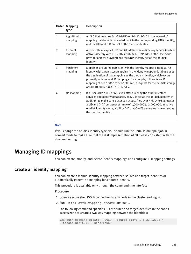
Order Mappingtype
Description
1 Algorithmicmapping
An SID that matches S-1-22-1-UID or S-1-22-2-GID in the internal IDmapping database is converted back to the corresponding UNIX identity,and the UID and GID are set as the on-disk identity.
2 Externalmapping
A user with an explicit UID and GID defined in a directory service (such asActive Directory with RFC 2307 attributes, LDAP, NIS, or the OneFS fileprovider or local provider) has the UNIX identity set as the on-diskidentity.
3 Persistentmapping
Mappings are stored persistently in the identity mapper database. Anidentity with a persistent mapping in the identity mapper database usesthe destination of that mapping as the on-disk identity, which occursprimarily with manual ID mappings. For example, if there is an IDmapping of GID:10000 to S-1-5-32-545, a request for the on-disk storageof GID:10000 returns S-1-5-32-545.
4 No mapping If a user lacks a UID or GID even after querying the other directoryservices and identity databases, its SID is set as the on-disk identity. Inaddition, to make sure a user can access files over NFS, OneFS allocatesa UID and GID from a preset range of 1,000,000 to 2,000,000. In nativeon-disk identity mode, a UID or GID that OneFS generates is never set asthe on-disk identity.
Note
If you change the on-disk identity type, you should run the PermissionRepair job inconvert mode to make sure that the disk representation of all files is consistent with thechanged setting.
Managing ID mappingsYou can create, modify, and delete identity mappings and configure ID mapping settings.
Create an identity mappingYou can create a manual identity mapping between source and target identities orautomatically generate a mapping for a source identity.
This procedure is available only through the command-line interface.
Procedure
1. Open a secure shell (SSH) connection to any node in the cluster and log in.
2. Run the isi auth mapping create command.
The following command specifies IDs of source and target identities in the zone3access zone to create a two-way mapping between the identities:
isi auth mapping create --2way --source-sid=S-1-5-21-12345 \--target-uid=5211 --zone=zone3
Identity management
Managing ID mappings 145
Modify an identity mappingYou can modify the configuration of an identity mapping.
This procedure is available only through the command-line interface.
Procedure
1. Open a secure shell (SSH) connection to any node in the cluster and log in.
2. Run the isi auth mapping modify command.
The following command modifies the mapping of the user with UID 4236 in the zone3access zone to include a reverse, 2-way mapping between the source and targetidentities:
isi auth mapping modify --source-uid=4236 \--target-sid=S-1-5-21-12345 --zone=zone3 --2way
Delete an identity mappingYou can delete one or more identity mappings.
This procedure is available only through the command-line interface.
Procedure
1. Open a secure shell (SSH) connection to any node in the cluster and log in.
2. Run the isi auth mapping delete command.
The following command deletes all identity mappings in the zone3 access zone:
isi auth mapping delete --all --zone=zone3
The following command deletes all identity mappings in the zone3 access zone thatwere both created automatically and include a UID or GID from an externalauthentication source:
isi auth mapping delete --all --only-external --zone=zone3
The following command deletes the identity mapping of the user with UID 4236 in thezone3 access zone:
isi auth mapping delete --source-uid=4236 --zone=zone3
View an identity mappingYou can display mapping information for a specific identity.
This procedure is available only through the command-line interface.
Procedure
1. Open a secure shell (SSH) connection to any node in the cluster and log in.
2. Run the isi auth mapping view command.
The following command displays mappings for the user with UID 4236 in the zone3access zone:
isi auth mapping view --uid=4236 --zone=zone3
Identity management
146 OneFS 7.2.1 Web Administration Guide

The system displays output similar to the following example:
Name: user_36 On-disk: UID: 4236Unix uid: 4236Unix gid: -100000 SMB: S-1-22-1-4236
Flush the identity mapping cacheYou can flush the ID map cache to remove in-memory copies of all or specific identitymappings.
Modifications to ID mappings may cause the cache to become out-of-sync and usersmight experience slowness or stalls when authenticating. You can flush the cache tosynchronize the mappings.
This procedure is available only through the command-line interface.
Procedure
1. Open a secure shell (SSH) connection to any node in the cluster and log in.
2. Run the isi auth mapping flush command.
The following command flushes all identity mappings on the EMC Isilon cluster:
isi auth mapping flush --all
The following command flushes the mapping of the user with UID 4236 in the zone3access zone:
isi auth mapping flush --source-uid-4236 --zone=zone3
View a user tokenYou can view the contents of an access token generated for a user during authentication.
This procedure is available only through the command-line interface.
Procedure
1. Open a secure shell (SSH) connection to any node in the cluster and log in.
2. Run the isi auth mapping token command.
The following command displays the access token of a user with UID 4236 in thezone3 access zone:
isi auth mapping token --uid=4236 --zone=zone3
The system displays output similar to the following example:
User Name: user_36 UID: 4236 SID: S-1-22-1-4236 On Disk: 4236ZID: 3Zone: zone3Privileges: -Primary Group Name: user_36 GID: 4236
Identity management
Flush the identity mapping cache 147
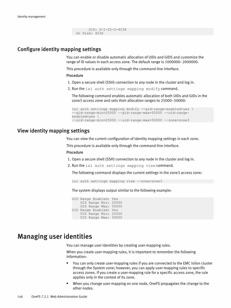
SID: S-1-22-2-4236 On Disk: 4236
Configure identity mapping settingsYou can enable or disable automatic allocation of UIDs and GIDS and customize therange of ID values in each access zone. The default range is 1000000–2000000.
This procedure is available only through the command-line interface.
Procedure
1. Open a secure shell (SSH) connection to any node in the cluster and log in.
2. Run the isi auth settings mapping modify command.
The following command enables automatic allocation of both UIDs and GIDs in thezone3 access zone and sets their allocation ranges to 25000–50000:
isi auth settings mapping modify --gid-range-enabled=yes \--gid-range-min=25000 --gid-range-max=50000 --uid-range-enabled=yes \--uid-range-min=25000 --uid-range-max=50000 --zone=zone3
View identity mapping settingsYou can view the current configuration of identity mapping settings in each zone.
This procedure is available only through the command-line interface.
Procedure
1. Open a secure shell (SSH) connection to any node in the cluster and log in.
2. Run the isi auth settings mapping view command.
The following command displays the current settings in the zone3 access zone:
isi auth settings mapping view --zone=zone3
The system displays output similar to the following example:
GID Range Enabled: Yes GID Range Min: 25000 GID Range Max: 50000UID Range Enabled: Yes UID Range Min: 25000 UID Range Max: 50000
Managing user identitiesYou can manage user identities by creating user-mapping rules.
When you create user-mapping rules, it is important to remember the followinginformation:
l You can only create user-mapping rules if you are connected to the EMC Isilon clusterthrough the System zone; however, you can apply user-mapping rules to specificaccess zones. If you create a user-mapping rule for a specific access zone, the ruleapplies only in the context of its zone.
l When you change user-mapping on one node, OneFS propagates the change to theother nodes.
Identity management
148 OneFS 7.2.1 Web Administration Guide
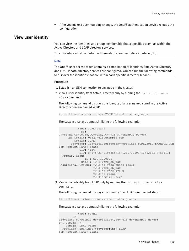
l After you make a user-mapping change, the OneFS authentication service reloads theconfiguration.
View user identityYou can view the identities and group membership that a specified user has within theActive Directory and LDAP directory services.
This procedure must be performed through the command-line interface (CLI).
Note
The OneFS user access token contains a combination of identities from Active Directoryand LDAP if both directory services are configured. You can run the following commandsto discover the identities that are within each specific directory service.
Procedure
1. Establish an SSH connection to any node in the cluster.
2. View a user identity from Active Directory only by running the isi auth usersview command.
The following command displays the identity of a user named stand in the ActiveDirectory domain named YORK:
isi auth users view --user=YORK\\stand --show-groups
The system displays output similar to the following example:
Name: YORK\stand DN: CN=stand,CN=Users,DC=york,DC=hull,DC=example,DC=com DNS Domain: york.hull.example.com Domain: YORK Provider: lsa-activedirectory-provider:YORK.HULL.EXAMPLE.COMSam Account Name: stand UID: 4326 SID: S-1-5-21-1195855716-1269722693-1240286574-591111 Primary Group ID : GID:1000000 Name : YORK\york_sh_udg Additional Groups: YORK\sd-york space group YORK\york_sh_udg YORK\sd-york-group YORK\sd-group YORK\domain users
3. Vew a user identity from LDAP only by running the isi auth users viewcommand.
The following command displays the identity of an LDAP user named stand:
isi auth user view --user=stand --show-groups
The system displays output similar to the following example:
Name: stand DN: uid=stand,ou=People,dc=colorado4,dc=hull,dc=example,dc=comDNS Domain: - Domain: LDAP_USERS Provider: lsa-ldap-provider:Unix LDAPSam Account Name: stand
Identity management
View user identity 149
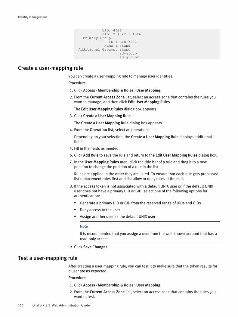
UID: 4326 SID: S-1-22-1-4326 Primary Group ID : GID:7222 Name : stand Additional Groups: stand sd-group sd-group2
Create a user-mapping ruleYou can create a user-mapping rule to manage user identities.
Procedure
1. Click Access > Membership & Roles > User Mapping.
2. From the Current Access Zone list, select an access zone that contains the rules youwant to manage, and then click Edit User Mapping Rules.
The Edit User Mapping Rules dialog box appears.
3. Click Create a User Mapping Rule.
The Create a User Mapping Rule dialog box appears.
4. From the Operation list, select an operation.
Depending on your selection, the Create a User Mapping Rule displays additionalfields.
5. Fill in the fields as needed.
6. Click Add Rule to save the rule and return to the Edit User Mapping Rules dialog box.
7. In the User Mapping Rules area, click the title bar of a rule and drag it to a newposition to change the position of a rule in the list.
Rules are applied in the order they are listed. To ensure that each rule gets processed,list replacement rules first and list allow or deny rules at the end.
8. If the access token is not associated with a default UNIX user or if the default UNIXuser does not have a primary UID or GID, select one of the following options forauthentication:
l Generate a primary UID or GID from the reserved range of UIDs and GIDs
l Deny access to the user
l Assign another user as the default UNIX user
Note
It is recommended that you assign a user from the well-known account that has aread-only access.
9. Click Save Changes.
Test a user-mapping ruleAfter creating a user-mapping rule, you can test it to make sure that the token results fora user are as expected.
Procedure
1. Click Access > Membership & Roles > User Mapping.
2. From the Current Access Zone list, select an access zone that contains the rules youwant to test.
Identity management
150 OneFS 7.2.1 Web Administration Guide
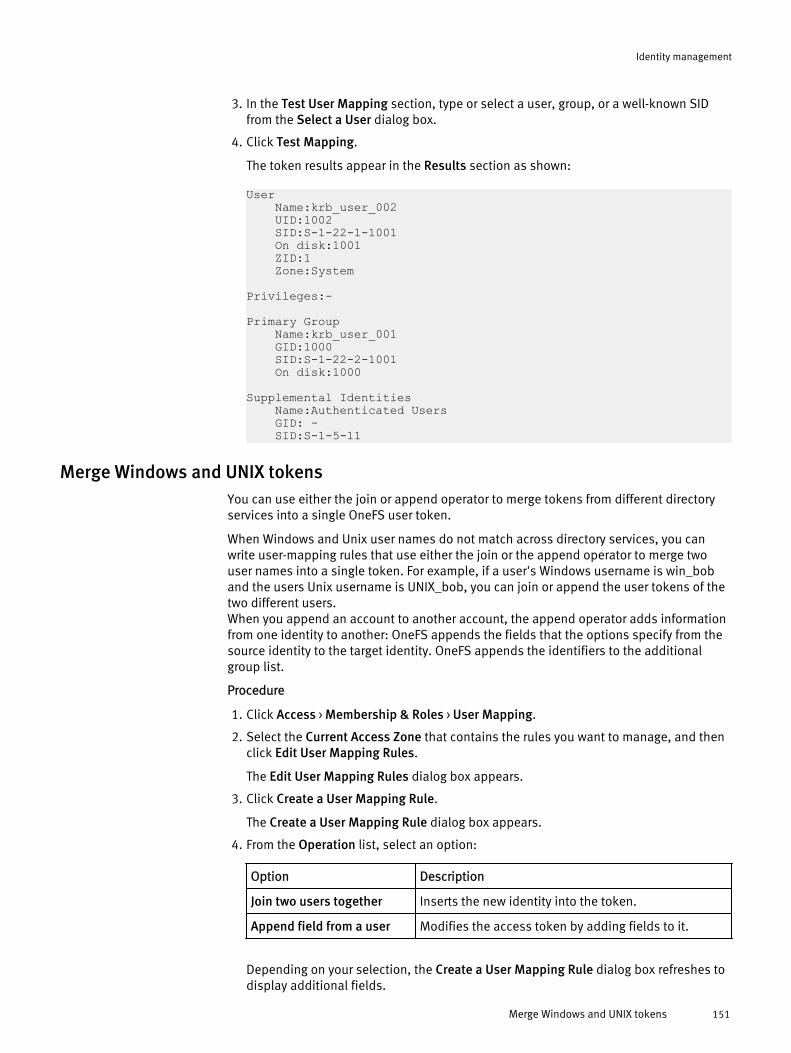
3. In the Test User Mapping section, type or select a user, group, or a well-known SIDfrom the Select a User dialog box.
4. Click Test Mapping.
The token results appear in the Results section as shown:
User Name:krb_user_002 UID:1002 SID:S-1-22-1-1001 On disk:1001 ZID:1 Zone:System Privileges:-
Primary Group Name:krb_user_001 GID:1000 SID:S-1-22-2-1001 On disk:1000
Supplemental Identities Name:Authenticated Users GID: - SID:S-1-5-11
Merge Windows and UNIX tokensYou can use either the join or append operator to merge tokens from different directoryservices into a single OneFS user token.
When Windows and Unix user names do not match across directory services, you canwrite user-mapping rules that use either the join or the append operator to merge twouser names into a single token. For example, if a user's Windows username is win_boband the users Unix username is UNIX_bob, you can join or append the user tokens of thetwo different users.When you append an account to another account, the append operator adds informationfrom one identity to another: OneFS appends the fields that the options specify from thesource identity to the target identity. OneFS appends the identifiers to the additionalgroup list.
Procedure
1. Click Access > Membership & Roles > User Mapping.
2. Select the Current Access Zone that contains the rules you want to manage, and thenclick Edit User Mapping Rules.
The Edit User Mapping Rules dialog box appears.
3. Click Create a User Mapping Rule.
The Create a User Mapping Rule dialog box appears.
4. From the Operation list, select an option:
Option Description
Join two users together Inserts the new identity into the token.
Append field from a user Modifies the access token by adding fields to it.
Depending on your selection, the Create a User Mapping Rule dialog box refreshes todisplay additional fields.
Identity management
Merge Windows and UNIX tokens 151
5. Populate the fields as needed.
6. Click Add Rule.
Note
Rules are called in the order they are listed. To ensure that each rule gets processed,list replacements first and allow/deny rules last. You can change the order in which arule is listed by clicking its title bar and dragging it to a new position.
7. Click Save Changes.
Retrieve the primary group from LDAPYou can create a user-mapping rule to insert primary group information from LDAP into auser's access token.
By default, the user-mapping service combines information from AD and LDAP but givesprecedence to the information from AD. You can create a mapping rule to control howOneFS combines the information, giving precedence to a primary group from LDAP ratherthan from Active Directory for a user.
Procedure
1. Click Access > Membership & Roles > User Mapping.
2. Select the Current Access Zone that contains the rules you want to manage, and thenclick Edit User Mapping Rules.
The Edit User Mapping Rules dialog box appears.
3. Click Create a User Mapping Rule.
The Create a User Mapping Rule dialog box appears.
4. From the Operation list, select Insert fields from a user.
The Create a User Mapping Rule dialog box refreshes to display additional fields.
5. To populate the Insert Fields into this User field, perform the following steps:
a. Click Browse.
The Select a User dialog box appears.
b. Select a user and an Active Directory authentication provider.
c. Click Search to view the search results.
d. Select a username and click Select to return to the Create a User Mapping Ruledialog box.
The primary group of the second user is inserted as the primary group of the firstuser.
6. Select the Insert primary group SID and GID check box.
7. To populate the Insert Fields from this User field, perform the following steps:
a. Click Browse.
The Select a User dialog box appears.
b. Select a user and an LDAP authentication provider.
c. Click Search to view the search results.
d. Select a username and click Select to return to the Create a User Mapping Ruledialog box.
Identity management
152 OneFS 7.2.1 Web Administration Guide

8. Click Add Rule.
Note
Rules are called in the order they are listed. To ensure that each rule gets processed,list the replacements first and the allow or deny rules at the end. You can change theorder in which a rule is listed by clicking its title bar and dragging it to a new position.
9. Click Save Changes.
Mapping rule optionsMapping rules can contain options that target the fields of an access token.
A field represents an aspect of a cross-domain access token, such as the primary UID andprimary user SID from a user that you select. You can see some of the fields in the OneFSweb administration interface. User in the web administration interface is the same asusername. You can also see fields in an access token by running the command isiauth mapping token.
When you create a rule, you can add an option to manipulate how OneFS combinesaspects of two identities into a single token. For example, an option can force OneFS toappend the supplement groups to a token.
A token includes the following fields that you can manipulate with user mapping rules:
l username
l unix_name
l primary_uid
l primary_user_sid
l primary_gid
l primary_group_sid
l additional_ids (includes supplemental groups)
Options control how a rule combines identity information in a token. The break option isthe exception: It stops OneFS from processing additional rules.
Although several options can apply to a rule, not all options apply to all operators. Thefollowing table describes the effect of each option and the operators that they work with.
Option Operator Description
user insert, append Copies the primary UID and primary user SID, if they exist, to thetoken.
groups insert, append Copies the primary GID and primary group SID, if they exist, to thetoken.
groups insert, append Copies all the additional identifiers to the token. The additionalidentifiers exclude the primary UID, the primary GID, the primaryuser SID, and the primary group SID.
default_user all operatorsexcept removegroups
If the mapping service fails to find the second user in a rule, theservice tries to find the username of the default user. The nameof the default user cannot include wildcards. When you set theoption for the default user in a rule with the command-lineinterface, you must set it with an underscore: default_user.
Identity management
Mapping rule options 153

Option Operator Description
break all operators Stops the mapping service from applying rules that follow theinsertion point of the break option. The mapping servicegenerates the final token at the point of the break.
Mapping rule operatorsThe operator determines what a mapping rule does.
You can create user-mapping rules through either the web-administration interface,where the operators are spelled out in a list, or from the command-line interface.
When you create a mapping rule with the OneFS command-line interface (CLI), you mustspecify an operator with a symbol. The operator affects the direction in which themapping service processes a rule. For more information about creating a mapping rule,see the white paper Managing identities with the Isilon OneFS user mapping service. Thefollowing table describes the operators that you can use in a mapping rule.
A mapping rule can contain only one operator.
Operator Web interface CLI Direction Description
append Append fieldsfrom a user
++ Left-to-right Modifies an access token by adding fields toit. The mapping service appends the fieldsthat are specified in the list of options (user,group, groups) to the first identity in therule. The fields are copied from the secondidentity in the rule. All appended identifiersbecome members of the additional groupslist. An append rule without an optionperforms only a lookup operation; you mustinclude an option to alter a token.
insert Insert fieldsfrom a user
+= Left-to-right Modifies an existing access token by addingfields to it. Fields specified in the optionslist (user, group, groups) are copied fromthe new identity and inserted into theidentity in the token. When the rule inserts aprimary user or primary group, it become thenew primary user and primary group in thetoken. The previous primary user andprimary group move to the additionalidentifiers list. Modifying the primary userleaves the token’s username unchanged.When inserting the additional groups froman identity, the service adds the new groupsto the existing groups.
replace Replace oneuser with adifferent user
=> Left-to-right Removes the token and replaces it with thenew token that is identified by the secondusername. If the second username is empty,the mapping service removes the firstusername in the token, leaving nousername. If a token contains no username,OneFS denies access with a no suchuser error.
Identity management
154 OneFS 7.2.1 Web Administration Guide

Operator Web interface CLI Direction Description
removegroups
Removesupplementalgroups from auser
-- Unary Modifies a token by removing thesupplemental groups.
join Join two userstogether
&= Bidirectional Inserts the new identity into the token. If thenew identity is the second user, themapping service inserts it after the existingidentity; otherwise, the service inserts itbefore the existing identity. The location ofthe insertion point is relevant when theexisting identity is already the first in the listbecause OneFS uses the first identity todetermine the ownership of new file systemobjects.
Identity management
Mapping rule operators 155

Identity management
156 OneFS 7.2.1 Web Administration Guide
CHAPTER 8
Home directories
This section contains the following topics:
l Home directories overview.................................................................................. 158l Home directory permissions................................................................................158l Authenticating SMB users................................................................................... 158l Home directory creation through SMB................................................................. 158l Home directory creation through SSH and FTP..................................................... 162l Home directory creation in a mixed environment................................................. 165l Interactions between ACLs and mode bits........................................................... 165l Default home directory settings in authentication providers................................ 165l Supported expansion variables...........................................................................166l Domain variables in home directory provisioning................................................ 168
Home directories 157
Home directories overviewWhen you create a local user, OneFS automatically creates a home directory for the user.OneFS also supports dynamic home directory provisioning for users who access thecluster by connecting to an SMB share or by logging in through FTP or SSH. Regardless ofthe method by which a home directory was created, you can configure access to thehome directory through a combination of SMB, SSH, and FTP.
Home directory permissionsYou can set up a user's home directory with a Windows ACL or with POSIX mode bits,which are then converted into a synthetic ACL. The method by which a home directory iscreated determines the initial permissions that are set on the home directory.
When you create a local user, the user's home directory is created with mode bits bydefault.
For users who authenticate against external sources, you can specify settings to createhome directories dynamically at login time. If a home directory is created during a loginthrough SSH or FTP, it is set up with mode bits; if a home directory is created during anSMB connection, it receives either mode bits or an ACL. For example, if an LDAP user firstlogs in through SSH or FTP, the user's home directory is created with mode bits. If thesame user first connects through an SMB share, the home directory is created with thepermissions indicated by the configured SMB settings. If the --inheritable-path-acl option is enabled, an ACL is generated; otherwise, mode bits are used.
Authenticating SMB usersYou can authenticate SMB users from authentication providers that can handle NThashes.
SMB sends an NT password hash to authenticate SMB users, so only users fromauthentication providers that can handle NT hashes can log in over SMB. The followingOneFS-supported authentication providers can handle NT hashes:
l Active Directory
l Local
l LDAPSAM (LDAP with Samba extensions enabled)
Home directory creation through SMBYou can create SMB shares by including expansion variables in the share path.Expansion variables give users to access their home directories by connecting to theshare. You can also enable dynamic provisioning of home directories that do not exist atSMB connection time.
Note
Share permissions are checked when files are accessed, before the underlying filesystem permissions are checked. Either of these permissions can prevent access to thefile or directory.
Home directories
158 OneFS 7.2.1 Web Administration Guide
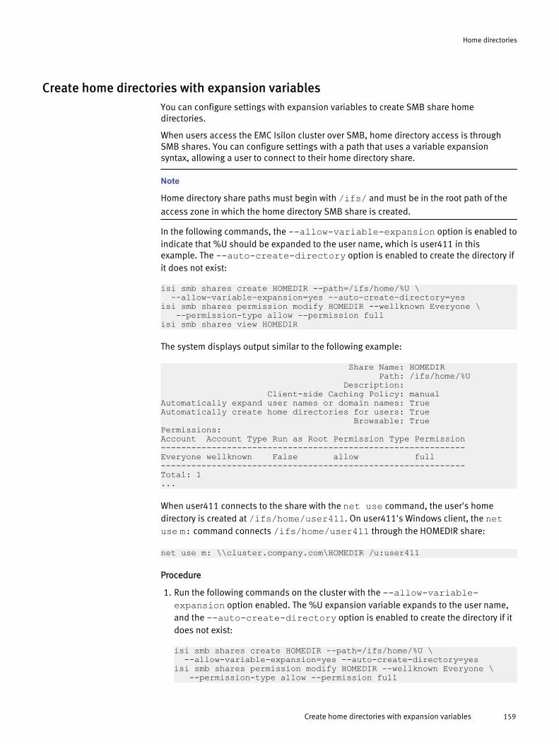
Create home directories with expansion variablesYou can configure settings with expansion variables to create SMB share homedirectories.
When users access the EMC Isilon cluster over SMB, home directory access is throughSMB shares. You can configure settings with a path that uses a variable expansionsyntax, allowing a user to connect to their home directory share.
Note
Home directory share paths must begin with /ifs/ and must be in the root path of the
access zone in which the home directory SMB share is created.
In the following commands, the --allow-variable-expansion option is enabled toindicate that %U should be expanded to the user name, which is user411 in thisexample. The --auto-create-directory option is enabled to create the directory ifit does not exist:
isi smb shares create HOMEDIR --path=/ifs/home/%U \ --allow-variable-expansion=yes --auto-create-directory=yes isi smb shares permission modify HOMEDIR --wellknown Everyone \ --permission-type allow --permission full isi smb shares view HOMEDIR
The system displays output similar to the following example:
Share Name: HOMEDIR Path: /ifs/home/%U Description: Client-side Caching Policy: manualAutomatically expand user names or domain names: TrueAutomatically create home directories for users: True Browsable: TruePermissions:Account Account Type Run as Root Permission Type Permission------------------------------------------------------------Everyone wellknown False allow full ------------------------------------------------------------Total: 1...
When user411 connects to the share with the net use command, the user's homedirectory is created at /ifs/home/user411. On user411's Windows client, the netuse m: command connects /ifs/home/user411 through the HOMEDIR share:
net use m: \\cluster.company.com\HOMEDIR /u:user411
Procedure
1. Run the following commands on the cluster with the --allow-variable-expansion option enabled. The %U expansion variable expands to the user name,and the --auto-create-directory option is enabled to create the directory if itdoes not exist:
isi smb shares create HOMEDIR --path=/ifs/home/%U \ --allow-variable-expansion=yes --auto-create-directory=yes isi smb shares permission modify HOMEDIR --wellknown Everyone \ --permission-type allow --permission full
Home directories
Create home directories with expansion variables 159
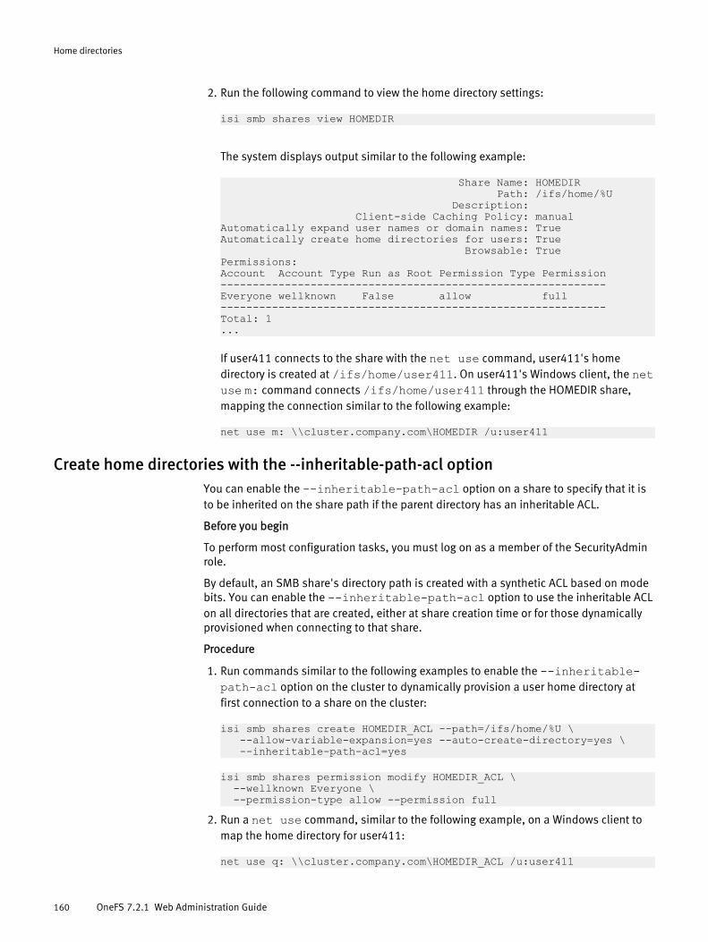
2. Run the following command to view the home directory settings:
isi smb shares view HOMEDIR
The system displays output similar to the following example:
Share Name: HOMEDIR Path: /ifs/home/%U Description: Client-side Caching Policy: manualAutomatically expand user names or domain names: TrueAutomatically create home directories for users: True Browsable: TruePermissions:Account Account Type Run as Root Permission Type Permission------------------------------------------------------------Everyone wellknown False allow full ------------------------------------------------------------Total: 1...
If user411 connects to the share with the net use command, user411's homedirectory is created at /ifs/home/user411. On user411's Windows client, the netuse m: command connects /ifs/home/user411 through the HOMEDIR share,mapping the connection similar to the following example:
net use m: \\cluster.company.com\HOMEDIR /u:user411
Create home directories with the --inheritable-path-acl optionYou can enable the --inheritable-path-acl option on a share to specify that it isto be inherited on the share path if the parent directory has an inheritable ACL.
Before you begin
To perform most configuration tasks, you must log on as a member of the SecurityAdminrole.
By default, an SMB share's directory path is created with a synthetic ACL based on modebits. You can enable the --inheritable-path-acl option to use the inheritable ACLon all directories that are created, either at share creation time or for those dynamicallyprovisioned when connecting to that share.
Procedure
1. Run commands similar to the following examples to enable the --inheritable-path-acl option on the cluster to dynamically provision a user home directory atfirst connection to a share on the cluster:
isi smb shares create HOMEDIR_ACL --path=/ifs/home/%U \ --allow-variable-expansion=yes --auto-create-directory=yes \ --inheritable-path-acl=yes
isi smb shares permission modify HOMEDIR_ACL \ --wellknown Everyone \ --permission-type allow --permission full
2. Run a net use command, similar to the following example, on a Windows client tomap the home directory for user411:
net use q: \\cluster.company.com\HOMEDIR_ACL /u:user411
Home directories
160 OneFS 7.2.1 Web Administration Guide
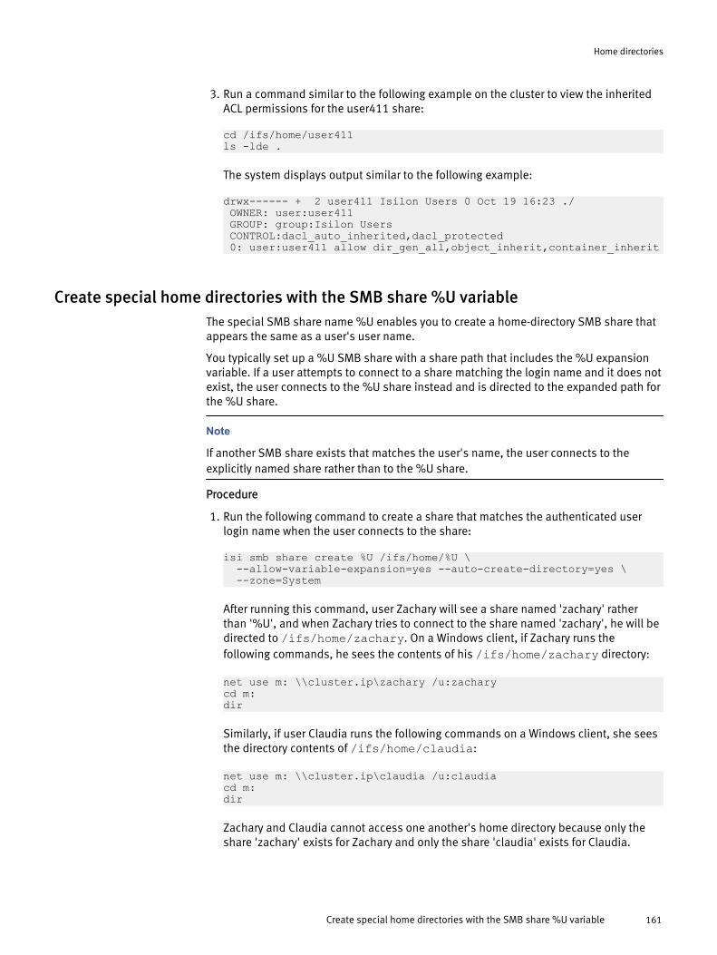
3. Run a command similar to the following example on the cluster to view the inheritedACL permissions for the user411 share:
cd /ifs/home/user411ls -lde .
The system displays output similar to the following example:
drwx------ + 2 user411 Isilon Users 0 Oct 19 16:23 ./ OWNER: user:user411 GROUP: group:Isilon Users CONTROL:dacl_auto_inherited,dacl_protected 0: user:user411 allow dir_gen_all,object_inherit,container_inherit
Create special home directories with the SMB share %U variableThe special SMB share name %U enables you to create a home-directory SMB share thatappears the same as a user's user name.
You typically set up a %U SMB share with a share path that includes the %U expansionvariable. If a user attempts to connect to a share matching the login name and it does notexist, the user connects to the %U share instead and is directed to the expanded path forthe %U share.
Note
If another SMB share exists that matches the user's name, the user connects to theexplicitly named share rather than to the %U share.
Procedure
1. Run the following command to create a share that matches the authenticated userlogin name when the user connects to the share:
isi smb share create %U /ifs/home/%U \ --allow-variable-expansion=yes --auto-create-directory=yes \ --zone=System
After running this command, user Zachary will see a share named 'zachary' ratherthan '%U', and when Zachary tries to connect to the share named 'zachary', he will bedirected to /ifs/home/zachary. On a Windows client, if Zachary runs thefollowing commands, he sees the contents of his /ifs/home/zachary directory:
net use m: \\cluster.ip\zachary /u:zachary cd m:dir
Similarly, if user Claudia runs the following commands on a Windows client, she seesthe directory contents of /ifs/home/claudia:
net use m: \\cluster.ip\claudia /u:claudia cd m: dir
Zachary and Claudia cannot access one another's home directory because only theshare 'zachary' exists for Zachary and only the share 'claudia' exists for Claudia.
Home directories
Create special home directories with the SMB share %U variable 161
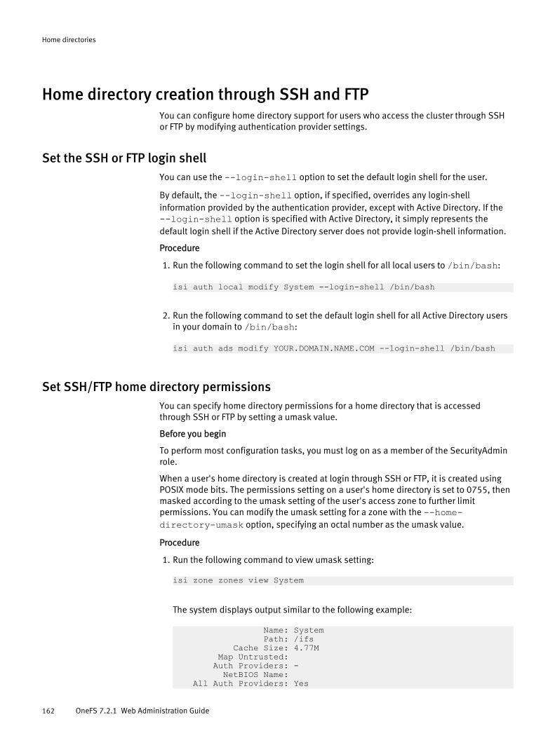
Home directory creation through SSH and FTPYou can configure home directory support for users who access the cluster through SSHor FTP by modifying authentication provider settings.
Set the SSH or FTP login shellYou can use the --login-shell option to set the default login shell for the user.
By default, the --login-shell option, if specified, overrides any login-shellinformation provided by the authentication provider, except with Active Directory. If the--login-shell option is specified with Active Directory, it simply represents thedefault login shell if the Active Directory server does not provide login-shell information.
Procedure
1. Run the following command to set the login shell for all local users to /bin/bash:
isi auth local modify System --login-shell /bin/bash
2. Run the following command to set the default login shell for all Active Directory usersin your domain to /bin/bash:
isi auth ads modify YOUR.DOMAIN.NAME.COM --login-shell /bin/bash
Set SSH/FTP home directory permissionsYou can specify home directory permissions for a home directory that is accessedthrough SSH or FTP by setting a umask value.
Before you begin
To perform most configuration tasks, you must log on as a member of the SecurityAdminrole.
When a user's home directory is created at login through SSH or FTP, it is created usingPOSIX mode bits. The permissions setting on a user's home directory is set to 0755, thenmasked according to the umask setting of the user's access zone to further limitpermissions. You can modify the umask setting for a zone with the --home-directory-umask option, specifying an octal number as the umask value.
Procedure
1. Run the following command to view umask setting:
isi zone zones view System
The system displays output similar to the following example:
Name: System Path: /ifs Cache Size: 4.77M Map Untrusted: Auth Providers: - NetBIOS Name: All Auth Providers: Yes
Home directories
162 OneFS 7.2.1 Web Administration Guide
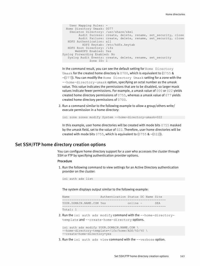
User Mapping Rules: - Home Directory Umask: 0077 Skeleton Directory: /usr/share/skel Audit Success: create, delete, rename, set_security, close Audit Failure: create, delete, rename, set_security, close HDFS Authentication: all HDFS Keytab: /etc/hdfs.keytab HDFS Root Directory: /ifs WebHDFS Enabled: YesSyslog Forwarding Enabled: No Syslog Audit Events: create, delete, rename, set_security Zone ID: 1
In the command result, you can see the default setting for Home DirectoryUmask for the created home directory is 0700, which is equivalent to (0755 &~(077)). You can modify the Home Directory Umask setting for a zone with the--home-directory-umask option, specifying an octal number as the umaskvalue. This value indicates the permissions that are to be disabled, so larger maskvalues indicate fewer permissions. For example, a umask value of 000 or 022 yieldscreated home directory permissions of 0755, whereas a umask value of 077 yieldscreated home directory permissions of 0700.
2. Run a command similar to the following example to allow a group/others write/execute permission in a home directory:
isi zone zones modify System --home-directory-umask=022
In this example, user home directories will be created with mode bits 0755 maskedby the umask field, set to the value of 022. Therefore, user home directories will becreated with mode bits 0755, which is equivalent to (0755 & ~(022)).
Set SSH/FTP home directory creation optionsYou can configure home directory support for a user who accesses the cluster throughSSH or FTP by specifying authentication provider options.
Procedure
1. Run the following command to view settings for an Active Directory authenticationprovider on the cluster:
isi auth ads list
The system displays output similar to the following example:
Name Authentication Status DC Name Site ---------------------------------------------------------YOUR.DOMAIN.NAME.COM Yes online - SEA---------------------------------------------------------Total: 1
2. Run the isi auth ads modify command with the --home-directory-template and --create-home-directory options.
isi auth ads modify YOUR.DOMAIN.NAME.COM \--home-directory-template=/ifs/home/ADS/%D/%U \--create-home-directory=yes
3. Run the isi auth ads view command with the --verbose option.
Home directories
Set SSH/FTP home directory creation options 163
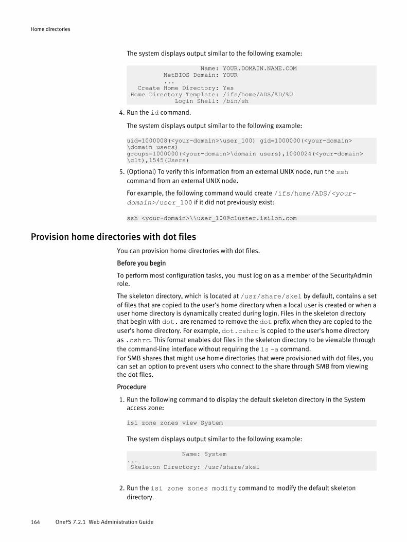
The system displays output similar to the following example:
Name: YOUR.DOMAIN.NAME.COM NetBIOS Domain: YOUR ... Create Home Directory: Yes Home Directory Template: /ifs/home/ADS/%D/%U Login Shell: /bin/sh
4. Run the id command.
The system displays output similar to the following example:
uid=1000008(<your-domain>\user_100) gid=1000000(<your-domain>\domain users) groups=1000000(<your-domain>\domain users),1000024(<your-domain>\c1t),1545(Users)
5. (Optional) To verify this information from an external UNIX node, run the sshcommand from an external UNIX node.
For example, the following command would create /ifs/home/ADS/<your-domain>/user_100 if it did not previously exist:
ssh <your-domain>\\[email protected]
Provision home directories with dot filesYou can provision home directories with dot files.
Before you begin
To perform most configuration tasks, you must log on as a member of the SecurityAdminrole.
The skeleton directory, which is located at /usr/share/skel by default, contains a setof files that are copied to the user's home directory when a local user is created or when auser home directory is dynamically created during login. Files in the skeleton directorythat begin with dot. are renamed to remove the dot prefix when they are copied to theuser's home directory. For example, dot.cshrc is copied to the user's home directoryas .cshrc. This format enables dot files in the skeleton directory to be viewable throughthe command-line interface without requiring the ls -a command.For SMB shares that might use home directories that were provisioned with dot files, youcan set an option to prevent users who connect to the share through SMB from viewingthe dot files.
Procedure
1. Run the following command to display the default skeleton directory in the Systemaccess zone:
isi zone zones view System
The system displays output similar to the following example:
Name: System... Skeleton Directory: /usr/share/skel
2. Run the isi zone zones modify command to modify the default skeletondirectory.
Home directories
164 OneFS 7.2.1 Web Administration Guide

The following command modifies the default skeleton directory, /usr/share/skel,in an access zone, where System is the value for the <zone> option and /usr/share/skel2 is the value for the <path> option:
isi zone zones modify System --skeleton-directory=/usr/share/skel2
Home directory creation in a mixed environmentIf a user logs in through both SMB and SSH, it is recommended that you configure homedirectory settings so the path template is the same for the SMB share and eachauthentication provider against which the user is authenticating through SSH.
Interactions between ACLs and mode bitsHome directory setup is determined by several factors, including how users authenticateand the options that specify home directory creation.
A user's home directory may be set up with either ACLs or POSIX mode bits, which areconverted into a synthetic ACL. The directory of a local user is created when the local useris created, and the directory is set up with POSIX mode bits by default. Directories can bedynamically provisioned at log in for users who authenticate against external sources,and in some cases for users who authenticate against the File provider. In this situation,the user home directory is created according to how the user first logs in.
For example, if an LDAP user first logs in through SSH or FTP and the user home directoryis created, it is created with POSIX mode bits. If that same user first connects through anSMB home directory share, the home directory is created as specified by the SMB optionsettings. If the --inherited-path-acl option is enabled, ACLs are generated.Otherwise, POSIX mode bits are used.
Default home directory settings in authentication providersThe default settings that affect how home directories are set up differ, based on theauthentication provider that the user authenticates against.
Authenticationprovider
Home directory Home directorycreation
UNIX login shell
Local l --home-directory-template=/ifs/home/%U
l --create-home-directory=yes
l --login-shell=/bin/sh
Enabled /bin/sh
File l --home-directory-template=""
Disabled None
Home directories
Home directory creation in a mixed environment 165
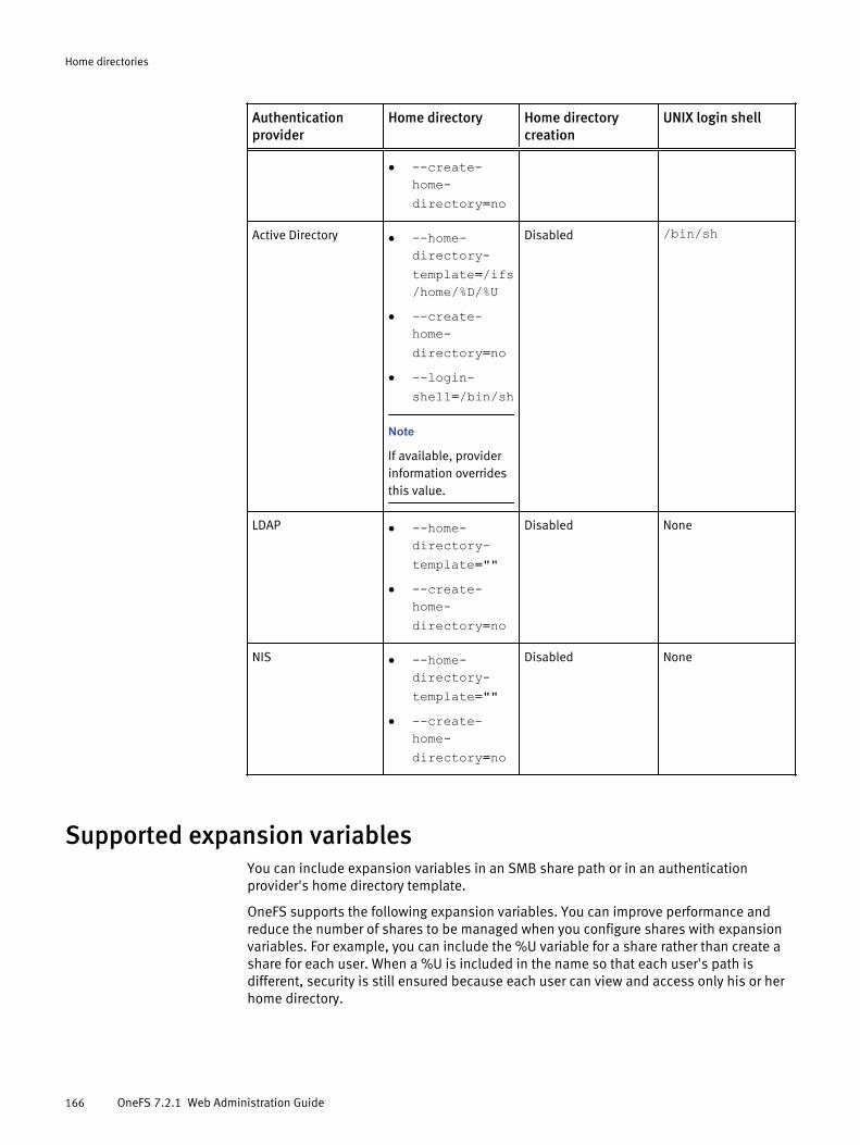
Authenticationprovider
Home directory Home directorycreation
UNIX login shell
l --create-home-directory=no
Active Directory l --home-directory-template=/ifs/home/%D/%U
l --create-home-directory=no
l --login-shell=/bin/sh
Note
If available, providerinformation overridesthis value.
Disabled /bin/sh
LDAP l --home-directory-template=""
l --create-home-directory=no
Disabled None
NIS l --home-directory-template=""
l --create-home-directory=no
Disabled None
Supported expansion variablesYou can include expansion variables in an SMB share path or in an authenticationprovider's home directory template.
OneFS supports the following expansion variables. You can improve performance andreduce the number of shares to be managed when you configure shares with expansionvariables. For example, you can include the %U variable for a share rather than create ashare for each user. When a %U is included in the name so that each user's path isdifferent, security is still ensured because each user can view and access only his or herhome directory.
Home directories
166 OneFS 7.2.1 Web Administration Guide
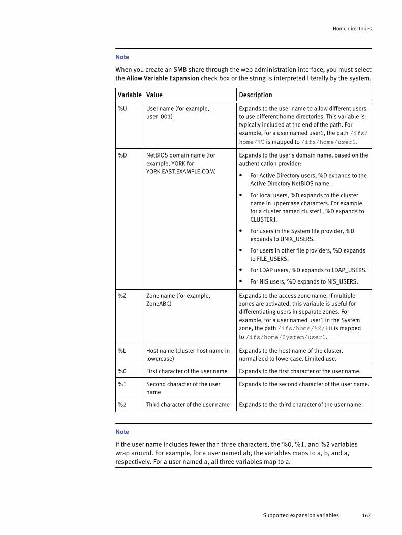
Note
When you create an SMB share through the web administration interface, you must selectthe Allow Variable Expansion check box or the string is interpreted literally by the system.
Variable Value Description
%U User name (for example,user_001)
Expands to the user name to allow different usersto use different home directories. This variable istypically included at the end of the path. Forexample, for a user named user1, the path /ifs/home/%U is mapped to /ifs/home/user1.
%D NetBIOS domain name (forexample, YORK forYORK.EAST.EXAMPLE.COM)
Expands to the user's domain name, based on theauthentication provider:
l For Active Directory users, %D expands to theActive Directory NetBIOS name.
l For local users, %D expands to the clustername in uppercase characters. For example,for a cluster named cluster1, %D expands toCLUSTER1.
l For users in the System file provider, %Dexpands to UNIX_USERS.
l For users in other file providers, %D expandsto FILE_USERS.
l For LDAP users, %D expands to LDAP_USERS.
l For NIS users, %D expands to NIS_USERS.
%Z Zone name (for example,ZoneABC)
Expands to the access zone name. If multiplezones are activated, this variable is useful fordifferentiating users in separate zones. Forexample, for a user named user1 in the Systemzone, the path /ifs/home/%Z/%U is mapped
to /ifs/home/System/user1.
%L Host name (cluster host name inlowercase)
Expands to the host name of the cluster,normalized to lowercase. Limited use.
%0 First character of the user name Expands to the first character of the user name.
%1 Second character of the username
Expands to the second character of the user name.
%2 Third character of the user name Expands to the third character of the user name.
Note
If the user name includes fewer than three characters, the %0, %1, and %2 variableswrap around. For example, for a user named ab, the variables maps to a, b, and a,respectively. For a user named a, all three variables map to a.
Home directories
Supported expansion variables 167
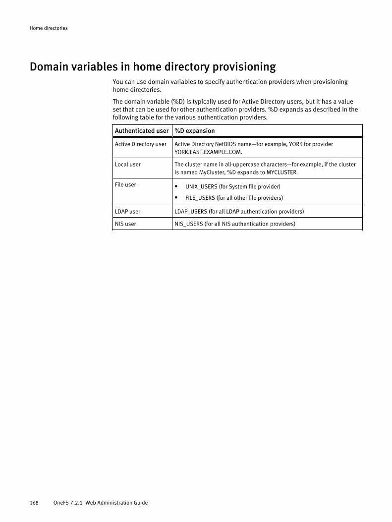
Domain variables in home directory provisioningYou can use domain variables to specify authentication providers when provisioninghome directories.
The domain variable (%D) is typically used for Active Directory users, but it has a valueset that can be used for other authentication providers. %D expands as described in thefollowing table for the various authentication providers.
Authenticated user %D expansion
Active Directory user Active Directory NetBIOS name—for example, YORK for providerYORK.EAST.EXAMPLE.COM.
Local user The cluster name in all-uppercase characters—for example, if the clusteris named MyCluster, %D expands to MYCLUSTER.
File user l UNIX_USERS (for System file provider)
l FILE_USERS (for all other file providers)
LDAP user LDAP_USERS (for all LDAP authentication providers)
NIS user NIS_USERS (for all NIS authentication providers)
Home directories
168 OneFS 7.2.1 Web Administration Guide
CHAPTER 9
Data access control
This section contains the following topics:
l Data access control overview.............................................................................. 170l ACLs....................................................................................................................170l UNIX permissions................................................................................................171l Mixed-permission environments......................................................................... 171l Managing access permissions.............................................................................172
Data access control 169

Data access control overviewOneFS supports two types of permissions data on files and directories that control whohas access: Windows-style access control lists (ACLs) and POSIX mode bits (UNIXpermissions). You can configure global policy settings that enable you to customizedefault ACL and UNIX permissions to best support your environment.
The OneFS file system installs with UNIX permissions as the default. You can give a file ordirectory an ACL by using Windows Explorer or OneFS administrative tools. Typically, filescreated over SMB or in a directory that has an ACL, receive an ACL. If a file receives anACL, OneFS stops enforcing the file's mode bits; the mode bits are provided for onlyprotocol compatibility, not for access control.
OneFS supports multiprotocol data access over Network File System (NFS) and ServerMessage Block (SMB) with a unified security model. A user is granted or denied the sameaccess to a file when using SMB for Windows file sharing as when using NFS for UNIX filesharing.
NFS enables Linux and UNIX clients to remotely mount any subdirectory, includingsubdirectories created by Windows or SMB users. Linux and UNIX clients also can mountACL-protected subdirectories created by a OneFS administrator. SMB provides Windowsusers access to files, directories and other file system resources stored by UNIX and Linuxsystems. In addition to Windows users, ACLs can affect local, NIS, and LDAP users.
By default, OneFS maintains the same file permissions regardless of the client’soperating system, the user’s identity management system, or the file sharing protocol.When OneFS must transform a file’s permissions from ACLs to mode bits or vice versa, itmerges the permissions into an optimal representation that uniquely balances userexpectations and file security.
ACLsIn Windows environments, file and directory permissions, referred to as access rights, aredefined in access control lists (ACLs). Although ACLs are more complex than mode bits,ACLs can express much more granular sets of access rules. OneFS checks the ACLprocessing rules commonly associated with Windows ACLs.
A Windows ACL contains zero or more access control entries (ACEs), each of whichrepresents the security identifier (SID) of a user or a group as a trustee. In OneFS, an ACLcan contain ACEs with a UID, GID, or SID as the trustee. Each ACE contains a set of rightsthat allow or deny access to a file or folder. An ACE can optionally contain an inheritanceflag to specify whether the ACE should be inherited by child folders and files.
Note
Instead of the standard three permissions available for mode bits, ACLs have 32 bits offine-grained access rights. Of these, the upper 16 bits are general and apply to all objecttypes. The lower 16 bits vary between files and directories but are defined in a way thatallows most applications to apply the same bits for files and directories.
Rights grant or deny access for a given trustee. You can block user access explicitlythrough a deny ACE or implicitly by ensuring that a user does not directly, or indirectlythrough a group, appear in an ACE that grants the right.
Data access control
170 OneFS 7.2.1 Web Administration Guide
UNIX permissionsIn a UNIX environment, file and directory access is controlled by POSIX mode bits, whichgrant read, write, or execute permissions to the owning user, the owning group, andeveryone else.
OneFS supports the standard UNIX tools for viewing and changing permissions, ls,chmod, and chown. For more information, run the man ls, man chmod, and manchown commands.
All files contain 16 permission bits, which provide information about the file or directorytype and the permissions. The lower 9 bits are grouped as three 3-bit sets, called triples,which contain the read, write, and execute (rwx) permissions for each class of users—owner, group, and other. You can set permissions flags to grant permissions to each ofthese classes.
Unless the user is root, OneFS checks the class to determine whether to grant or denyaccess to the file. The classes are not cumulative: The first class matched is applied. It istherefore common to grant permissions in decreasing order.
Mixed-permission environmentsWhen a file operation requests an object’s authorization data, for example, with the ls -l command over NFS or with the Security tab of the Properties dialog box in WindowsExplorer over SMB, OneFS attempts to provide that data in the requested format. In anenvironment that mixes UNIX and Windows systems, some translation may be requiredwhen performing create file, set security, get security, or access operations.
NFS access of Windows-created filesIf a file contains an owning user or group that is a SID, the system attempts to map it to acorresponding UID or GID before returning it to the caller.
In UNIX, authorization data is retrieved by calling stat(2) on a file and examining theowner, group, and mode bits. Over NFSv3, the GETATTR command functions similarly. Thesystem approximates the mode bits and sets them on the file whenever its ACL changes.Mode bit approximations need to be retrieved only to service these calls.
Note
SID-to-UID and SID-to-GID mappings are cached in both the OneFS ID mapper and thestat cache. If a mapping has recently changed, the file might report inaccurateinformation until the file is updated or the cache is flushed.
SMB access of UNIX-created filesNo UID-to-SID or GID-to-SID mappings are performed when creating an ACL for a file; allUIDs and GIDs are converted to SIDs or principals when the ACL is returned.
OneFS initiates a two-step process for returning a security descriptor, which containsSIDs for the owner and primary group of an object:
1. The current security descriptor is retrieved from the file. If the file does not have adiscretionary access control list (DACL), a synthetic ACL is constructed from the file’slower 9 mode bits, which are separated into three sets of permission triples—one
Data access control
UNIX permissions 171
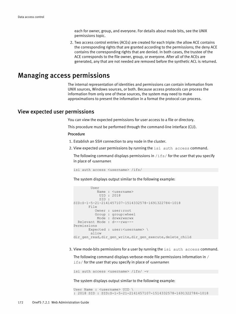
each for owner, group, and everyone. For details about mode bits, see the UNIXpermissions topic.
2. Two access control entries (ACEs) are created for each triple: the allow ACE containsthe corresponding rights that are granted according to the permissions; the deny ACEcontains the corresponding rights that are denied. In both cases, the trustee of theACE corresponds to the file owner, group, or everyone. After all of the ACEs aregenerated, any that are not needed are removed before the synthetic ACL is returned.
Managing access permissionsThe internal representation of identities and permissions can contain information fromUNIX sources, Windows sources, or both. Because access protocols can process theinformation from only one of these sources, the system may need to makeapproximations to present the information in a format the protocol can process.
View expected user permissionsYou can view the expected permissions for user access to a file or directory.
This procedure must be performed through the command-line interface (CLI).
Procedure
1. Establish an SSH connection to any node in the cluster.
2. View expected user permissions by running the isi auth access command.
The following command displays permissions in /ifs/ for the user that you specifyin place of <username>:
isi auth access <username> /ifs/
The system displays output similar to the following example:
User Name : <username> UID : 2018 SID : SID:S-1-5-21-2141457107-1514332578-1691322784-1018 File Owner : user:root Group : group:wheel Mode : drwxrwxrwx Relevant Mode : d---rwx--- Permissions Expected : user:<username> \ allow dir_gen_read,dir_gen_write,dir_gen_execute,delete_child
3. View mode-bits permissions for a user by running the isi auth access command.
The following command displays verbose-mode file permissions information in /ifs/ for the user that you specify in place of <username>:
isi auth access <username> /ifs/ -v
The system displays output similar to the following example:
User Name : <username> UID \: 2018 SID : SID:S-1-5-21-2141457107-1514332578-1691322784-1018
Data access control
172 OneFS 7.2.1 Web Administration Guide
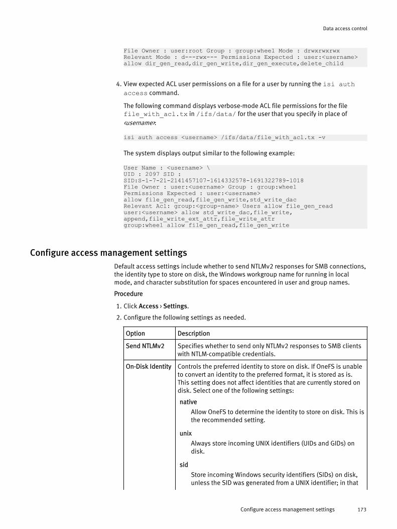
File Owner : user:root Group : group:wheel Mode : drwxrwxrwx Relevant Mode : d---rwx--- Permissions Expected : user:<username>allow dir_gen_read,dir_gen_write,dir_gen_execute,delete_child
4. View expected ACL user permissions on a file for a user by running the isi authaccess command.
The following command displays verbose-mode ACL file permissions for the filefile_with_acl.tx in /ifs/data/ for the user that you specify in place of<username>:
isi auth access <username> /ifs/data/file_with_acl.tx -v
The system displays output similar to the following example:
User Name : <username> \UID : 2097 SID : SID:S-1-7-21-2141457107-1614332578-1691322789-1018 File Owner : user:<username> Group : group:wheel Permissions Expected : user:<username> allow file_gen_read,file_gen_write,std_write_dac Relevant Acl: group:<group-name> Users allow file_gen_read user:<username> allow std_write_dac,file_write,append,file_write_ext_attr,file_write_attr group:wheel allow file_gen_read,file_gen_write
Configure access management settingsDefault access settings include whether to send NTLMv2 responses for SMB connections,the identity type to store on disk, the Windows workgroup name for running in localmode, and character substitution for spaces encountered in user and group names.
Procedure
1. Click Access > Settings.
2. Configure the following settings as needed.
Option Description
Send NTLMv2 Specifies whether to send only NTLMv2 responses to SMB clientswith NTLM-compatible credentials.
On-Disk Identity Controls the preferred identity to store on disk. If OneFS is unableto convert an identity to the preferred format, it is stored as is.This setting does not affect identities that are currently stored ondisk. Select one of the following settings:
native
Allow OneFS to determine the identity to store on disk. This isthe recommended setting.
unix
Always store incoming UNIX identifiers (UIDs and GIDs) ondisk.
sid
Store incoming Windows security identifiers (SIDs) on disk,unless the SID was generated from a UNIX identifier; in that
Data access control
Configure access management settings 173
Option Description
case, convert it back to the UNIX identifier and store it ondisk.
Workgroup Specifies the NetBIOS workgroup. The default value isWORKGROUP.
SpaceReplacement
For clients that have difficulty parsing spaces in user and groupnames, specifies a substitute character.
3. Click Save.
After you finish
If you changed the on-disk identity selection, it is recommended that you run thePermissionRepair job with the Convert repair type to prevent potential permissionserrors. For more information, see Update cluster permissions on page 180.
Modify ACL policy settingsYou can modify ACL policy settings but the default ACL policy settings are sufficient formost cluster deployments.
CAUTION
Because ACL policies change the behavior of permissions throughout the system, theyshould be modified only as necessary by experienced administrators with advancedknowledge of Windows ACLs. This is especially true for the advanced settings, which areapplied regardless of the cluster's environment.
For UNIX, Windows, or balanced environments, the optimal permission policy settings areselected and cannot be modified. However, you can choose to manually configure thecluster's default permission settings if necessary to support your particular environment.
Note
You must be logged in to the web administration interface to perform this task.
Procedure
1. Click Protocols > ACLs > ACL Policies.
2. In the Standard Settings area, under Environment, select the option that bestdescribes your environment, or select Configure permission policies manually toconfigure individual permission policies.
3. If you selected the Configure permission policies manually option, configure thesettings as needed.
For more information about these settings, see ACL policy settings options.
4. In the Advanced Settings area, configure the settings as needed.
Data access control
174 OneFS 7.2.1 Web Administration Guide
ACL policy settings optionsYou can configure an ACL policy by choosing from the available settings options.
Environment settings
UNIX only
Causes cluster permissions to operate with UNIX semantics, as opposed to Windowssemantics. Enabling this option prevents ACL creation on the system.
Balanced
Causes cluster permissions to operate in a mixed UNIX and Windows environment.This setting is recommended for most cluster deployments.
Windows only
Causes cluster permissions to operate with Windows semantics, as opposed to UNIXsemantics. Enabling this option causes the system to return an error on UNIX chmodrequests.
Configure permission policies manually
Allows you to configure the individual permissions policy settings available underPermission Policies.
Permission policies settings
ACL creation over SMB
Specifies whether to allow or deny creation of ACLs over SMB. Select one of thefollowing options.
Do not allow the creation of ACLs over Windows File Sharing (SMB)
Prevents ACL creation on the cluster.
Allow the creation of ACLs over SMB
Allows ACL creation on the cluster.
Note
Inheritable ACLs on the system take precedence over this setting: If inheritable ACLsare set on a folder, any new files and folders created in that folder will inherit thefolder's ACL. Disabling this setting does not remove ACLs currently set on files. If youwant to clear an existing ACL, run the chmod -b <mode> <file> command to remove
the ACL and set the correct permissions.
chmod on files with existing ACLs
Controls what happens when a chmod operation is initiated on a file with an ACL,either locally or over NFS. This setting controls any elements that set UNIXpermissions, including File System Explorer. Enabling this policy setting does notchange how chmod operations affect files that do not have ACLs. Select one of thefollowing options.
Remove the existing ACL and set UNIX permissions instead
For chmod operations, removes any existing ACL and instead sets the chmodpermissions. Select this option only if you do not need permissions to be setfrom Windows.
Data access control
ACL policy settings options 175
Remove the existing ACL and create an ACL equivalent to the UNIX permissions
Stores the UNIX permissions in a Windows ACL. Select this option only if youwant to remove Windows permissions but do not want files to have syntheticACLs.
Remove the existing ACL and create an ACL equivalent to the UNIX permissions, forall users/groups referenced in old ACL
Stores the UNIX permissions in a Windows ACL. Select this option only if youwant to remove Windows permissions but do not want files to have syntheticACLs.
Merge the new permissions with the existing ACL
Causes Windows and UNIX permissions to operate smoothly in a balancedenvironment by merging permissions that are applied by chmod with existingACLs. An ACE for each identity (owner, group, and everyone) is either modifiedor created, but all other ACEs are unmodified. Inheritable ACEs are also leftunmodified to enable Windows users to continue to inherit appropriatepermissions. UNIX users can set specific permissions for each of those threestandard identities, however.
Deny permission to modify the ACL
Prevents users from making NFS and local chmod operations. Enable thissetting if you do not want to allow permission sets over NFS.
Ignore operation if file has an existing ACL
Prevents an NFS client from making changes to the ACL. Select this option if youdefined an inheritable ACL on a directory and want to use that ACL forpermissions.
CAUTION
If you try to run the chmod command on the same permissions that are currently set
on a file with an ACL, you may cause the operation to silently fail—The operationappears to be successful, but if you were to examine the permissions on the cluster,you would notice that the chmod command had no effect. As a workaround, you can
run the chmod command away from the current permissions and then perform a
second chmod command to revert to the original permissions. For example, if your
file shows 755 UNIX permissions and you want to confirm this number, you couldrun chmod 700 file; chmod 755 file.
ACLs created on directories by UNIX chmodOn Windows systems, the access control entries for directories can define fine-grained rules for inheritance; on UNIX, the mode bits are not inherited. Making ACLsthat are created on directories by the chmod command inheritable is more secure fortightly controlled environments but may deny access to some Windows users whowould otherwise expect access.Select one of the following options.
l Make them inheritable
l Do not make them inheritable
chown/chgrp on files with existing ACLs
Changes a file or folder's owning user or group. Select one of the following options.
Data access control
176 OneFS 7.2.1 Web Administration Guide

Modify the owner and/or group
Causes the chown or chgrp operation to perform as it does in UNIX. Enablingthis setting modifies any ACEs in the ACL associated with the old and newowner or group.
Modify the owner and/or group and ACL permissions
Cause the NFS chown or chgrp operation to function as it does in Windows.When a file owner is changed over Windows, no permissions in the ACL arechanged.
Ignore operation if file has an existing ACL
Prevents an NFS client from making changes to the owner or group.
Note
Over NFS, the chown or chgrp operation changes the permissions and the owner or
owning group. For example, consider a file owned by user Joe with rwx------ (700)permissions, signifying rwx permissions for the owner, but no permissions foranyone else. If you run the chown command to change ownership of the file to user
Bob, the owner permissions are still rwx but they now represent the permissions forBob, rather than for Joe, who lost all of his permissions. This setting does not affectUNIX chown or chgrp operations performed on files with UNIX permissions, and it
does not affect Windows chown or chgrp operations, which do not change any
permissions.
Access checks (chmod, chown)
In UNIX environments, only the file owner or superuser has the right to run a chmodor chown operation on a file. In Windows environments, you can implement thispolicy setting to give users the right to perform chmod operations, called the changepermissions right, or the right to perform chown operations, called the takeownership right.
Note
The take ownership right only gives users the ability to take file ownership, not togive ownership away.
Select one of the following options.
Allow only owners to chmod or chown
Causes chmod and chown access checks to operate with UNIX-like behavior.
Allow owner and users with 'take ownership' right to chown, and owner and userswith 'change permissions' right to chmod
Causes chmod and chown access checks to operate with Windows-likebehavior.
Advanced settings
Treatment of 'rwx' permissions
In UNIX environments, rwx permissions signify two things: A user or group has read,write, and execute permissions; and a user or group has the maximum possible levelof permissions.
Data access control
ACL policy settings options 177
When you assign UNIX permissions to a file, no ACLs are stored for that file. AWindows system processes only ACLs; Windows does not process UNIX permissions.Therefore, when you view a file's permissions on a Windows system, the clustermust translate the UNIX permissions into an ACL. This type of ACL is called asynthetic ACL. Synthetic ACLs are not stored anywhere; instead, they are dynamicallygenerated as needed and then they are discarded. If a file has UNIX permissions,you may notice synthetic ACLs when you run the ls file command on the cluster toview a file’s ACLs.
When you generate a synthetic ACL, the cluster maps UNIX permissions to Windowsrights. Windows supports a more granular permissions model than UNIX does, and itspecifies rights that cannot easily be mapped from UNIX permissions. If the clustermaps rwx permissions to Windows rights, you must enable one of the followingoptions. The main difference between rwx and Full Control is the broader set ofpermissions with Full Control.
Select one of the following options.
Retain 'rwx' permissions
Generates an ACE that provides only read, write, and execute permissions.
Treat 'rwx' permissions as Full Control
Generates an ACE that provides the maximum Windows permissions for a useror a group by adding the change permissions right, the take ownership right,and the delete right.
Group owner inheritance
Operating systems tend to work with group ownership and permissions in twodifferent ways: BSD inherits the group owner from the file's parent folder; Windowsand Linux inherit the group owner from the file creator's primary group. If you enablea setting that causes the group owner to be inherited from the creator's primarygroup, you can override it on a per-folder basis by running the chmod command toset the set-gid bit. This inheritance applies only when the file is created. For moreinformation, see the manual page for the chmod command.Select one of the following options.
When an ACL exists, use Linux and Windows semantics, otherwise use BSDsemantics
Controls file behavior based on whether the new file inherits ACLs from itsparent folder. If it does, the file uses the creator's primary group. If it does not,the file inherits from its parent folder.
BSD semantics - Inherit group owner from the parent folder
Causes the group owner to be inherited from the file's parent folder.
Linux and Windows semantics - Inherit group owner from the creator's primarygroup
Causes the group owner to be inherited from the file creator's primary group.
chmod (007) on files with existing ACLs
Specifies whether to remove ACLs when running the chmod (007) command.Select one of the following options.
chmod(007) does not remove existing ACL
Sets 007 UNIX permissions without removing an existing ACL.
Data access control
178 OneFS 7.2.1 Web Administration Guide
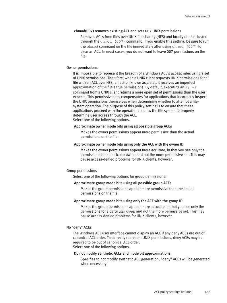
chmod(007) removes existing ACL and sets 007 UNIX permissions
Removes ACLs from files over UNIX file sharing (NFS) and locally on the clusterthrough the chmod (007) command. If you enable this setting, be sure to runthe chmod command on the file immediately after using chmod (007) toclear an ACL. In most cases, you do not want to leave 007 permissions on thefile.
Owner permissions
It is impossible to represent the breadth of a Windows ACL's access rules using a setof UNIX permissions. Therefore, when a UNIX client requests UNIX permissions for afile with an ACL over NFS, an action known as a stat, it receives an imperfectapproximation of the file's true permissions. By default, executing an ls -lcommand from a UNIX client returns a more open set of permissions than the userexpects. This permissiveness compensates for applications that incorrectly inspectthe UNIX permissions themselves when determining whether to attempt a file-system operation. The purpose of this policy setting is to ensure that theseapplications proceed with the operation to allow the file system to properlydetermine user access through the ACL.Select one of the following options.
Approximate owner mode bits using all possible group ACEs
Makes the owner permissions appear more permissive than the actualpermissions on the file.
Approximate owner mode bits using only the ACE with the owner ID
Makes the owner permissions appear more accurate, in that you see only thepermissions for a particular owner and not the more permissive set. This maycause access-denied problems for UNIX clients, however.
Group permissions
Select one of the following options for group permissions:
Approximate group mode bits using all possible group ACEs
Makes the group permissions appear more permissive than the actualpermissions on the file.
Approximate group mode bits using only the ACE with the group ID
Makes the group permissions appear more accurate, in that you see only thepermissions for a particular group and not the more permissive set. This maycause access-denied problems for UNIX clients, however.
No "deny" ACEs
The Windows ACL user interface cannot display an ACL if any deny ACEs are out ofcanonical ACL order. To correctly represent UNIX permissions, deny ACEs may berequired to be out of canonical ACL order.Select one of the following options.
Do not modify synthetic ACLs and mode bit approximations
Specifies to not modify synthetic ACL generation; “deny” ACEs will be generatedwhen necessary.
Data access control
ACL policy settings options 179
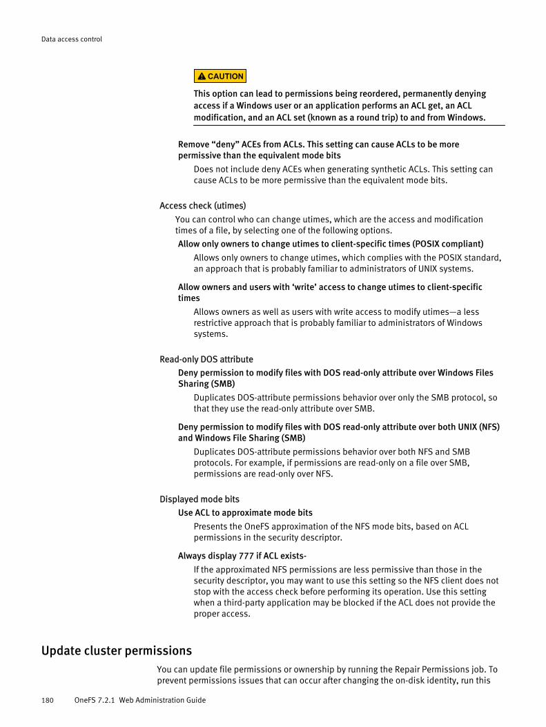
CAUTION
This option can lead to permissions being reordered, permanently denyingaccess if a Windows user or an application performs an ACL get, an ACLmodification, and an ACL set (known as a round trip) to and from Windows.
Remove “deny” ACEs from ACLs. This setting can cause ACLs to be morepermissive than the equivalent mode bits
Does not include deny ACEs when generating synthetic ACLs. This setting cancause ACLs to be more permissive than the equivalent mode bits.
Access check (utimes)
You can control who can change utimes, which are the access and modificationtimes of a file, by selecting one of the following options.
Allow only owners to change utimes to client-specific times (POSIX compliant)
Allows only owners to change utimes, which complies with the POSIX standard,an approach that is probably familiar to administrators of UNIX systems.
Allow owners and users with ‘write’ access to change utimes to client-specifictimes
Allows owners as well as users with write access to modify utimes—a lessrestrictive approach that is probably familiar to administrators of Windowssystems.
Read-only DOS attribute
Deny permission to modify files with DOS read-only attribute over Windows FilesSharing (SMB)
Duplicates DOS-attribute permissions behavior over only the SMB protocol, sothat they use the read-only attribute over SMB.
Deny permission to modify files with DOS read-only attribute over both UNIX (NFS)and Windows File Sharing (SMB)
Duplicates DOS-attribute permissions behavior over both NFS and SMBprotocols. For example, if permissions are read-only on a file over SMB,permissions are read-only over NFS.
Displayed mode bits
Use ACL to approximate mode bits
Presents the OneFS approximation of the NFS mode bits, based on ACLpermissions in the security descriptor.
Always display 777 if ACL exists-
If the approximated NFS permissions are less permissive than those in thesecurity descriptor, you may want to use this setting so the NFS client does notstop with the access check before performing its operation. Use this settingwhen a third-party application may be blocked if the ACL does not provide theproper access.
Update cluster permissionsYou can update file permissions or ownership by running the Repair Permissions job. Toprevent permissions issues that can occur after changing the on-disk identity, run this
Data access control
180 OneFS 7.2.1 Web Administration Guide
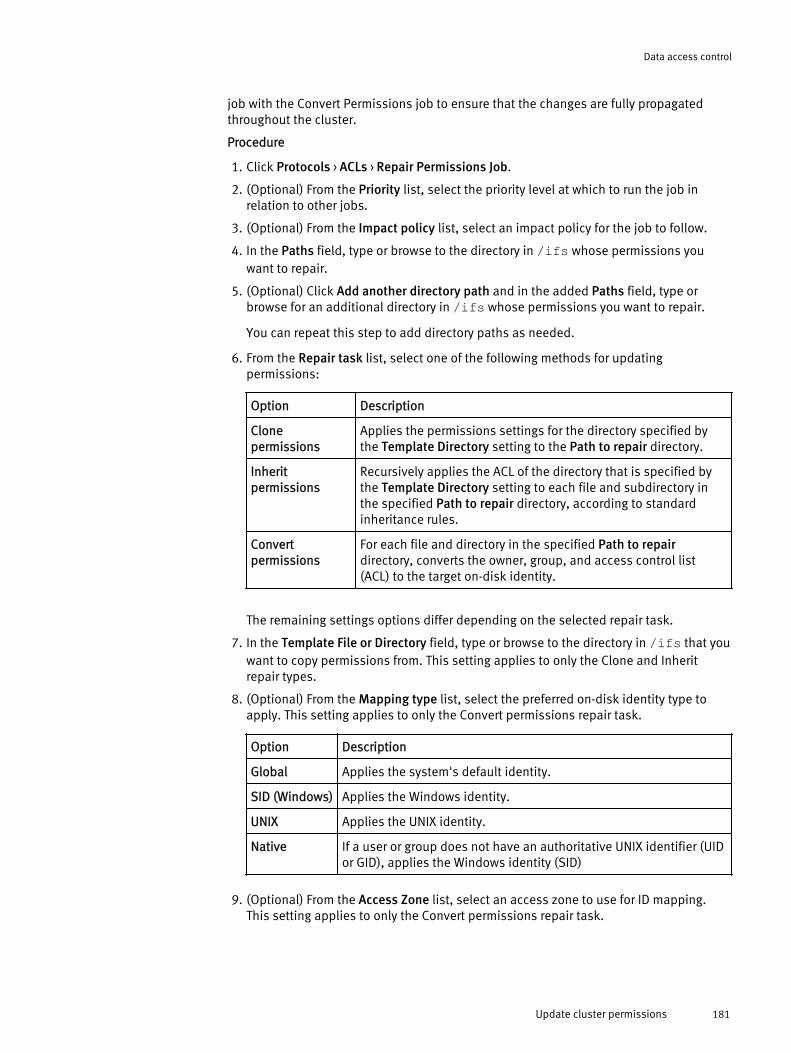
job with the Convert Permissions job to ensure that the changes are fully propagatedthroughout the cluster.
Procedure
1. Click Protocols > ACLs > Repair Permissions Job.
2. (Optional) From the Priority list, select the priority level at which to run the job inrelation to other jobs.
3. (Optional) From the Impact policy list, select an impact policy for the job to follow.
4. In the Paths field, type or browse to the directory in /ifs whose permissions youwant to repair.
5. (Optional) Click Add another directory path and in the added Paths field, type orbrowse for an additional directory in /ifs whose permissions you want to repair.
You can repeat this step to add directory paths as needed.
6. From the Repair task list, select one of the following methods for updatingpermissions:
Option Description
Clonepermissions
Applies the permissions settings for the directory specified bythe Template Directory setting to the Path to repair directory.
Inheritpermissions
Recursively applies the ACL of the directory that is specified bythe Template Directory setting to each file and subdirectory inthe specified Path to repair directory, according to standardinheritance rules.
Convertpermissions
For each file and directory in the specified Path to repairdirectory, converts the owner, group, and access control list(ACL) to the target on-disk identity.
The remaining settings options differ depending on the selected repair task.
7. In the Template File or Directory field, type or browse to the directory in /ifs that youwant to copy permissions from. This setting applies to only the Clone and Inheritrepair types.
8. (Optional) From the Mapping type list, select the preferred on-disk identity type toapply. This setting applies to only the Convert permissions repair task.
Option Description
Global Applies the system's default identity.
SID (Windows) Applies the Windows identity.
UNIX Applies the UNIX identity.
Native If a user or group does not have an authoritative UNIX identifier (UIDor GID), applies the Windows identity (SID)
9. (Optional) From the Access Zone list, select an access zone to use for ID mapping.This setting applies to only the Convert permissions repair task.
Data access control
Update cluster permissions 181

Data access control
182 OneFS 7.2.1 Web Administration Guide
CHAPTER 10
File sharing
This section contains the following topics:
l File sharing overview...........................................................................................184l SMB.................................................................................................................... 186l NFS..................................................................................................................... 200l FTP...................................................................................................................... 211l HTTP and HTTPS.................................................................................................. 211
File sharing 183
File sharing overviewMulti-protocol support in OneFS enables files and directories on the Isilon cluster to beaccessed through SMB for Windows file sharing, NFS for UNIX file sharing, secure shell(SSH), FTP, and HTTP. By default, only the SMB and NFS protocols are enabled.
OneFS creates the /ifs directory, which is the root directory for all file system data onthe cluster. The /ifs directory is configured as an SMB share and an NFS export bydefault. You can create additional shares and exports within the /ifs directory tree.
Note
We recommend that you do not save data to the root /ifs file path but in directories
below /ifs. The design of your data storage structure should be planned carefully. A
well-designed directory structure optimizes cluster performance and administration.
You can set Windows- and UNIX-based permissions on OneFS files and directories. Userswho have the required permissions and administrative privileges can create, modify, andread data on the cluster through one or more of the supported file sharing protocols.
l SMB. Allows Microsoft Windows and Mac OS X clients to access files that are storedon the cluster.
l NFS. Allows Linux and UNIX clients that adhere to the RFC1813 (NFSv3) and RFC3530(NFSv4) specifications to access files that are stored on the cluster.
l HTTP and HTTPS (with optional DAV). Allows clients to access files that are stored onthe cluster through a web browser.
l FTP. Allows any client that is equipped with an FTP client program to access files thatare stored on the cluster through the FTP protocol.
Mixed protocol environmentsThe /ifs directory is the root directory for all file system data in the cluster, serving asan SMB share, an NFS export, and a document root directory. You can create additionalshares and exports within the /ifs directory tree. You can configure your OneFS clusterto use SMB or NFS exclusively. You can also enable HTTP, FTP, and SSH.
Access rights are consistently enforced across access protocols on all security models. Auser is granted or denied the same rights to a file whether using SMB or NFS. Clustersrunning OneFS support a set of global policy settings that enable you to customize thedefault access control list (ACL) and UNIX permissions settings.
OneFS is configured with standard UNIX permissions on the file tree. Through WindowsExplorer or OneFS administrative tools, you can give any file or directory an ACL. Inaddition to Windows domain users and groups, ACLs in OneFS can include local, NIS, andLDAP users and groups. After a file is given an ACL, the mode bits are no longer enforcedand exist only as an estimate of the effective permissions.
Note
We recommend that you configure ACL and UNIX permissions only if you fully understandhow they interact with one another.
File sharing
184 OneFS 7.2.1 Web Administration Guide

Write caching with SmartCacheWrite caching accelerates the process of writing data to the cluster. OneFS includes awrite-caching feature called SmartCache, which is enabled by default for all files anddirectories.
If write caching is enabled, OneFS writes data to a write-back cache instead ofimmediately writing the data to disk. OneFS can write the data to disk at a time that ismore convenient.
Note
We recommend that you keep write caching enabled. You should also enable writecaching for all file pool policies.
OneFS interprets writes to the cluster as either synchronous or asynchronous, dependingon a client's specifications. The impacts and risks of write caching depend on whatprotocols clients use to write to the cluster, and whether the writes are interpreted assynchronous or asynchronous. If you disable write caching, client specifications areignored and all writes are performed synchronously.
The following table explains how clients' specifications are interpreted, according to theprotocol.
Protocol Synchronous Asynchronous
NFS The stable field is set to data_sync or
file_sync.
The stable field is set to unstable.
SMB The write-through flag has been
applied.
The write-through flag has not been
applied.
Write caching for asynchronous writesWriting to the cluster asynchronously with write caching is the fastest method of writingdata to your cluster.
Write caching for asynchronous writes requires fewer cluster resources than write cachingfor synchronous writes, and will improve overall cluster performance for most workflows.However, there is some risk of data loss with asynchronous writes.
The following table describes the risk of data loss for each protocol when write cachingfor asynchronous writes is enabled:
Protocol Risk
NFS If a node fails, no data will be lost except in the unlikely event that a client of thatnode also crashes before it can reconnect to the cluster. In that situation,asynchronous writes that have not been committed to disk will be lost.
SMB If a node fails, asynchronous writes that have not been committed to disk will be lost.
We recommend that you do not disable write caching, regardless of the protocol that youare writing with. If you are writing to the cluster with asynchronous writes, and you decidethat the risks of data loss are too great, we recommend that you configure your clients touse synchronous writes, rather than disable write caching.
File sharing
Write caching with SmartCache 185
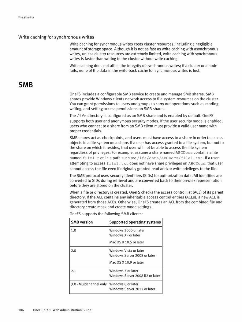
Write caching for synchronous writesWrite caching for synchronous writes costs cluster resources, including a negligibleamount of storage space. Although it is not as fast as write caching with asynchronouswrites, unless cluster resources are extremely limited, write caching with synchronouswrites is faster than writing to the cluster without write caching.
Write caching does not affect the integrity of synchronous writes; if a cluster or a nodefails, none of the data in the write-back cache for synchronous writes is lost.
SMBOneFS includes a configurable SMB service to create and manage SMB shares. SMBshares provide Windows clients network access to file system resources on the cluster.You can grant permissions to users and groups to carry out operations such as reading,writing, and setting access permissions on SMB shares.
The /ifs directory is configured as an SMB share and is enabled by default. OneFSsupports both user and anonymous security modes. If the user security mode is enabled,users who connect to a share from an SMB client must provide a valid user name withproper credentials.
SMB shares act as checkpoints, and users must have access to a share in order to accessobjects in a file system on a share. If a user has access granted to a file system, but not tothe share on which it resides, that user will not be able to access the file systemregardless of privileges. For example, assume a share named ABCDocs contains a filenamed file1.txt in a path such as: /ifs/data/ABCDocs/file1.txt. If a userattempting to access file1.txt does not have share privileges on ABCDocs, that usercannot access the file even if originally granted read and/or write privileges to the file.
The SMB protocol uses security identifiers (SIDs) for authorization data. All identities areconverted to SIDs during retrieval and are converted back to their on-disk representationbefore they are stored on the cluster.
When a file or directory is created, OneFS checks the access control list (ACL) of its parentdirectory. If the ACL contains any inheritable access control entries (ACEs), a new ACL isgenerated from those ACEs. Otherwise, OneFS creates an ACL from the combined file anddirectory create mask and create mode settings.
OneFS supports the following SMB clients:
SMB version Supported operating systems
1.0 Windows 2000 or laterWindows XP or later
Mac OS X 10.5 or later
2.0 Windows Vista or laterWindows Server 2008 or later
Mac OS X 10.9 or later
2.1 Windows 7 or laterWindows Server 2008 R2 or later
3.0 - Multichannel only Windows 8 or laterWindows Server 2012 or later
File sharing
186 OneFS 7.2.1 Web Administration Guide

SMB shares in access zonesYou can create and manage SMB shares within access zones.
You can create access zones that partition storage on the EMC Isilon cluster into multiplevirtual containers. Access zones support all configuration settings for authentication andidentity management services on the cluster, so you can configure authenticationproviders and provision SMB shares on a zone-by-zone basis. When you create an accesszone, a local provider is created automatically, which allows you to configure each accesszone with a list of local users and groups. You can also authenticate through a differentActive Directory provider in each access zone, and you can control data access bydirecting incoming connections to the access zone from a specific IP address in a pool.Associating an access zone with an IP address pool restricts authentication to theassociated access zone and reduces the number of available and accessible SMB shares.
Here are a few ways to simplify SMB management with access zones:
l Migrate multiple SMB servers, such as Windows file servers or NetApp filers, to asingle Isilon cluster, and then configure a separate access zone for each SMB server.
l Configure each access zone with a unique set of SMB share names that do notconflict with share names in other access zones, and then join each access zone to adifferent Active Directory domain.
l Reduce the number of available and accessible shares to manage by associating anIP address pool with an access zone to restrict authentication to the zone.
l Configure default SMB share settings that apply to all shares in an access zone.
The Isilon cluster includes a built-in access zone named System, where you manage allaspects of the cluster and other access zones. If you don't specify an access zone whenmanaging SMB shares, OneFS will default to the System zone.
SMB MultichannelSMB Multichannel supports establishing a single SMB session over multiple networkconnections.
SMB Multichannel is a feature of the SMB 3.0 protocol that provides the followingcapabilities:
Increased throughput
OneFS can transmit more data to a client through multiple connections over highspeed network adapters or over multiple network adapters.
Connection failure tolerance
When an SMB Multichannel session is established over multiple networkconnections, the session is not lost if one of the connections has a network fault,which enables the client to continue to work.
Automatic discovery
SMB Multichannel automatically discovers supported hardware configurations onthe client that have multiple available network paths and then negotiates andestablishes a session over multiple network connections. You are not required toinstall components, roles, role services, or features.
File sharing
SMB shares in access zones 187
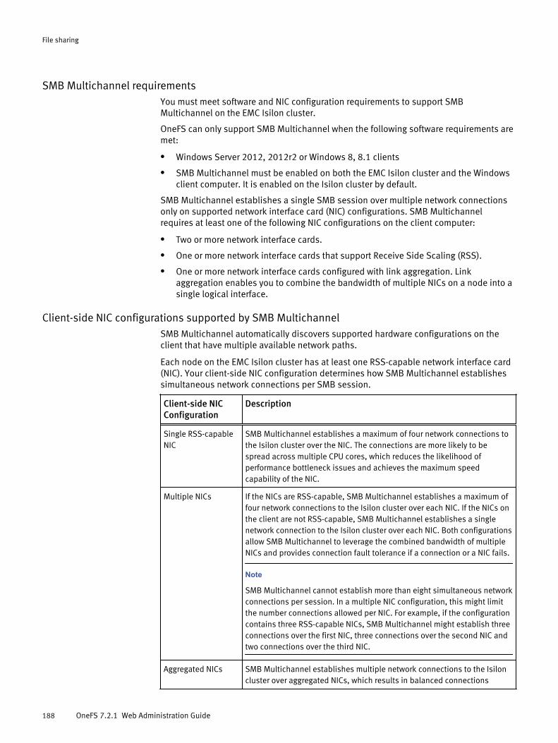
SMB Multichannel requirementsYou must meet software and NIC configuration requirements to support SMBMultichannel on the EMC Isilon cluster.
OneFS can only support SMB Multichannel when the following software requirements aremet:
l Windows Server 2012, 2012r2 or Windows 8, 8.1 clients
l SMB Multichannel must be enabled on both the EMC Isilon cluster and the Windowsclient computer. It is enabled on the Isilon cluster by default.
SMB Multichannel establishes a single SMB session over multiple network connectionsonly on supported network interface card (NIC) configurations. SMB Multichannelrequires at least one of the following NIC configurations on the client computer:
l Two or more network interface cards.
l One or more network interface cards that support Receive Side Scaling (RSS).
l One or more network interface cards configured with link aggregation. Linkaggregation enables you to combine the bandwidth of multiple NICs on a node into asingle logical interface.
Client-side NIC configurations supported by SMB MultichannelSMB Multichannel automatically discovers supported hardware configurations on theclient that have multiple available network paths.
Each node on the EMC Isilon cluster has at least one RSS-capable network interface card(NIC). Your client-side NIC configuration determines how SMB Multichannel establishessimultaneous network connections per SMB session.
Client-side NICConfiguration
Description
Single RSS-capableNIC
SMB Multichannel establishes a maximum of four network connections tothe Isilon cluster over the NIC. The connections are more likely to bespread across multiple CPU cores, which reduces the likelihood ofperformance bottleneck issues and achieves the maximum speedcapability of the NIC.
Multiple NICs If the NICs are RSS-capable, SMB Multichannel establishes a maximum offour network connections to the Isilon cluster over each NIC. If the NICs onthe client are not RSS-capable, SMB Multichannel establishes a singlenetwork connection to the Isilon cluster over each NIC. Both configurationsallow SMB Multichannel to leverage the combined bandwidth of multipleNICs and provides connection fault tolerance if a connection or a NIC fails.
Note
SMB Multichannel cannot establish more than eight simultaneous networkconnections per session. In a multiple NIC configuration, this might limitthe number connections allowed per NIC. For example, if the configurationcontains three RSS-capable NICs, SMB Multichannel might establish threeconnections over the first NIC, three connections over the second NIC andtwo connections over the third NIC.
Aggregated NICs SMB Multichannel establishes multiple network connections to the Isiloncluster over aggregated NICs, which results in balanced connections
File sharing
188 OneFS 7.2.1 Web Administration Guide
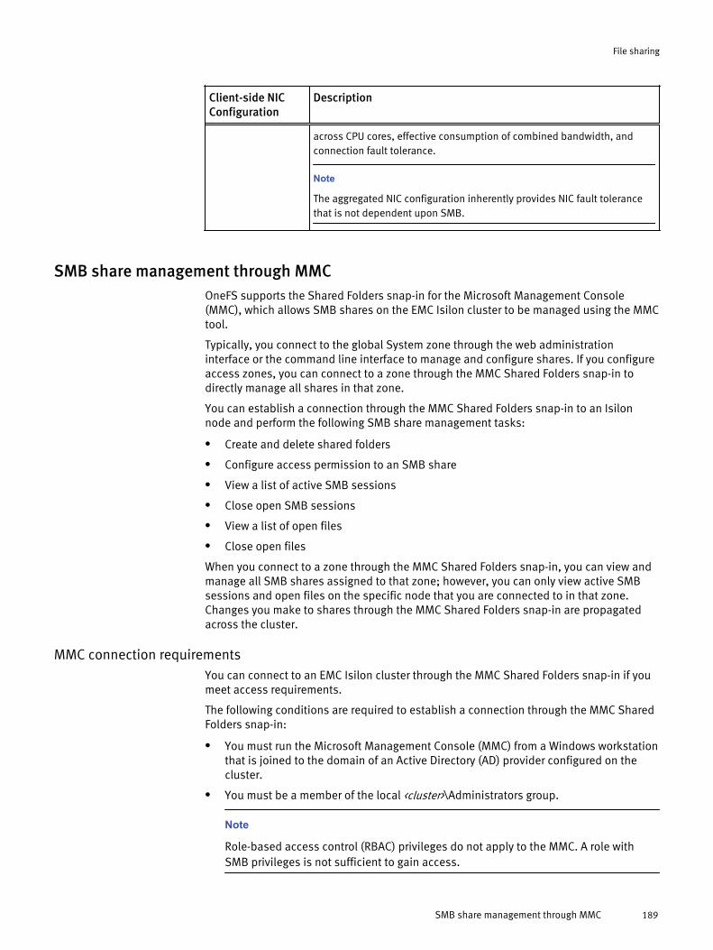
Client-side NICConfiguration
Description
across CPU cores, effective consumption of combined bandwidth, andconnection fault tolerance.
Note
The aggregated NIC configuration inherently provides NIC fault tolerancethat is not dependent upon SMB.
SMB share management through MMCOneFS supports the Shared Folders snap-in for the Microsoft Management Console(MMC), which allows SMB shares on the EMC Isilon cluster to be managed using the MMCtool.
Typically, you connect to the global System zone through the web administrationinterface or the command line interface to manage and configure shares. If you configureaccess zones, you can connect to a zone through the MMC Shared Folders snap-in todirectly manage all shares in that zone.
You can establish a connection through the MMC Shared Folders snap-in to an Isilonnode and perform the following SMB share management tasks:
l Create and delete shared folders
l Configure access permission to an SMB share
l View a list of active SMB sessions
l Close open SMB sessions
l View a list of open files
l Close open files
When you connect to a zone through the MMC Shared Folders snap-in, you can view andmanage all SMB shares assigned to that zone; however, you can only view active SMBsessions and open files on the specific node that you are connected to in that zone.Changes you make to shares through the MMC Shared Folders snap-in are propagatedacross the cluster.
MMC connection requirementsYou can connect to an EMC Isilon cluster through the MMC Shared Folders snap-in if youmeet access requirements.
The following conditions are required to establish a connection through the MMC SharedFolders snap-in:
l You must run the Microsoft Management Console (MMC) from a Windows workstationthat is joined to the domain of an Active Directory (AD) provider configured on thecluster.
l You must be a member of the local <cluster>\Administrators group.
Note
Role-based access control (RBAC) privileges do not apply to the MMC. A role withSMB privileges is not sufficient to gain access.
File sharing
SMB share management through MMC 189

l You must log in to a Windows workstation as an Active Directory user that is amember of the local <cluster>\Administrators group.
Symbolic links and SMB clientsOneFS enables SMB2 clients to access symbolic links in a seamless manner. Manyadministrators deploy symbolic links to virtually reorder file system hierarchies,especially when crucial files or directories are scattered around an environment.
In an SMB share, a symbolic link (also known as a symlink or a soft link) is a type of filethat contains a path to a target file or directory. Symbolic links are transparent toapplications running on SMB clients, and they function as typical files and directories.Support for relative and absolute links is enabled by the SMB client. The specificconfiguration depends on the client type and version.
A symbolic link that points to a network file or directory that is not in the path of theactive SMB session is referred to as an absolute (or remote) link. Absolute links alwayspoint to the same location on a file system, regardless of the present working directory,and usually contain the root directory as part of the path. Conversely, a relative link is asymbolic link that points directly to a user's or application's working directory, so you donot have to specify the full absolute path when creating the link.
OneFS exposes symbolic links through the SMB2 protocol, enabling SMB2 clients toresolve the links instead of relying on OneFS to resolve the links on behalf of the clients.To transverse a relative or absolute link, the SMB client must be authenticated to theSMB shares that the link can be followed through. However, if the SMB client does nothave permission to access the share, access to the target is denied and Windows will notprompt the user for credentials.
SMB2 and NFS links are interoperable for relative links only. For maximum compatibility,create these links from a POSIX client.
Note
SMB1 clients (such as Windows XP or 2002) may still use relative links, but they aretraversed on the server side and referred to as "shortcut files." Absolute links do not workin these environments.
Enabling symbolic linksBefore you can fully use symbolic links in an SMB environment, you must enable them.
For Windows SMB clients to traverse each type of symbolic link, you must enable them onthe client. Windows supports the following link types:
l local to local
l remote to remote
l local to remote
l remote to local
You must run the following Windows command to enable all four link types:
fsutil behavior set SymlinkEvaluation L2L:1 R2R:1 L2R:1 R2L:1
File sharing
190 OneFS 7.2.1 Web Administration Guide
For POSIX clients using Samba, you must set the following options in the [global]section of your Samba configuration file (smb.conf) to enable Samba clients to traverserelative and absolute links:
follow symlinks=yes wide links=yes
In this case, "wide links" in the smb.conf file refers to absolute links. The defaultsetting in this file is no.
Managing symbolic linksAfter enabling symbolic links, you can create or delete them from the Windows commandprompt or a POSIX command line.
Create symbolic links using the Windows mklink command on an SMB2 client or the lncommand from a POSIX command-line interface. For example, an administrator may wantto give a user named User1 access to a file named File1.doc in the /ifs/data/directory without giving specific access to that directory by creating a link named Link1:
mklink \ifs\home\users\User1\Link1 \ifs\data\Share1\File1.doc
When you create a symbolic link, it is designated as a file link or directory link. Once thelink is set, the designation cannot be changed. You can format symbolic link paths aseither relative or absolute.
To delete symbolic links, use the del command in Windows, or the rm command in aPOSIX environment.
Keep in mind that when you delete a symbolic link, the target file or directory still exists.However, when you delete a target file or directory, a symbolic link continues to exist andstill points to the old target, thus becoming a broken link.
Anonymous access to SMB sharesYou can configure anonymous access to SMB shares by enabling the local Guest user andallowing impersonation of the guest user.
For example, if you store files such as browser executables or other data that is public onthe internet, anonymous access allows any user to access the SMB share withoutauthenticating.
Managing SMB settingsYou can enable or disable the SMB service, configure global settings for the SMB service,and configure default SMB share settings that are specific to each access zone.
Configure SMB server settingsYou can enable or disable the SMB server and configure global settings for SMB sharesand snapshot directories.
CAUTION
Modifying the advanced settings could result in operational failures. Be aware of thepotential consequences before committing changes to these settings.
File sharing
Anonymous access to SMB shares 191

Procedure
1. Click Protocols > Windows Sharing (SMB) > SMB Server Settings.
2. From the SMB service setting, select Enabled.
3. From the Snapshot Directory Settings box, choose the system default or a customconfiguration for the following settings:
l Visible at root
l Accessible at root
l Visible in subdirectories
l Accessible in subdirectories
4. Click Save.
Configure default SMB share settingsYou can configure SMB share settings specific to each access zone.
The default settings are applied to all new shares that are added to the access zone.
CAUTION
If you modify the default settings, the changes are applied to all existing shares in theaccess zone unless the setting was configured at the SMB share level.
Procedure
1. Click Protocols > Windows Sharing (SMB) > SMB Default Share Settings.
2. From the Current Access Zones drop-down list, select the access zone that the defaultsettings will apply to.
3. From the File and Directory Permissions Settings box, choose the system default or acustom configuration for the following settings:
l Create Permissions
l Create Mask (Dir)
l Create Mode (Dir)
l Create Mask (File)
l Create Mode (File)
4. From the Performance Settings box, choose the system default or a customconfiguration for the following settings:
l Change Notify
l Oplocks
Performance settings are advanced and should only be modified if necessary.
5. From the Security Settings box, choose the system default or a custom configurationfor the following settings:
l Impersonate Guest
l Impersonate User
l NTFS ACL
l Access Based Enumeration
l HOST ACL
File sharing
192 OneFS 7.2.1 Web Administration Guide
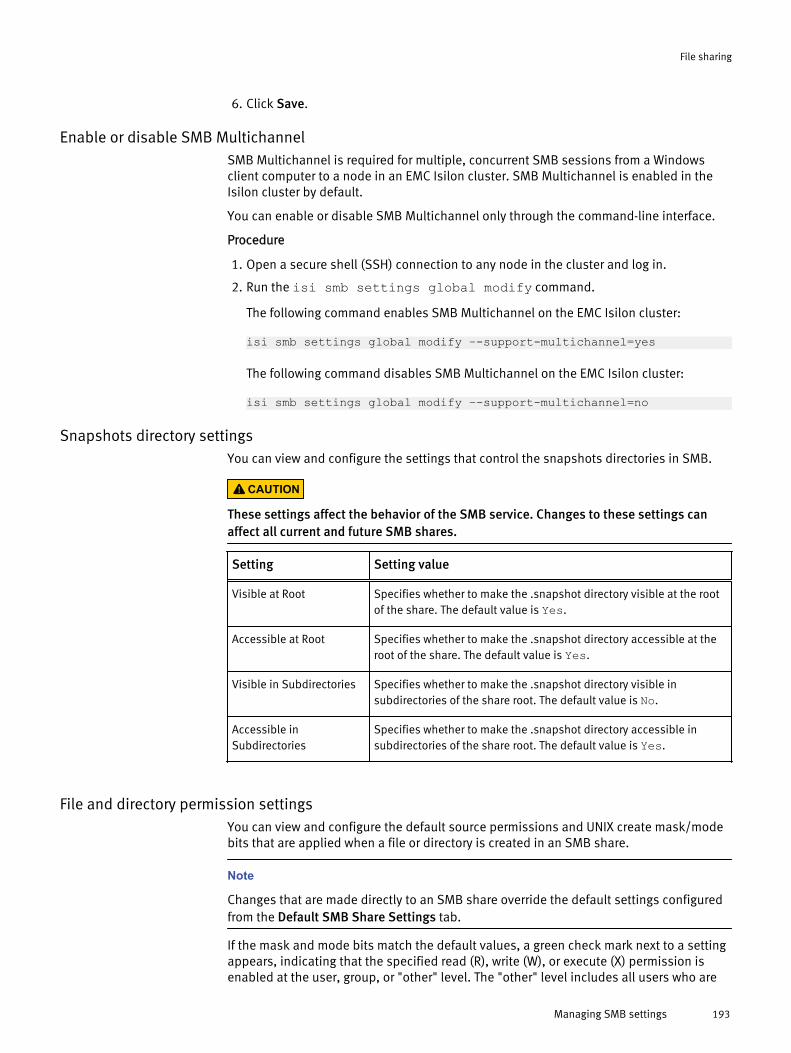
6. Click Save.
Enable or disable SMB MultichannelSMB Multichannel is required for multiple, concurrent SMB sessions from a Windowsclient computer to a node in an EMC Isilon cluster. SMB Multichannel is enabled in theIsilon cluster by default.
You can enable or disable SMB Multichannel only through the command-line interface.
Procedure
1. Open a secure shell (SSH) connection to any node in the cluster and log in.
2. Run the isi smb settings global modify command.
The following command enables SMB Multichannel on the EMC Isilon cluster:
isi smb settings global modify –-support-multichannel=yes
The following command disables SMB Multichannel on the EMC Isilon cluster:
isi smb settings global modify –-support-multichannel=no
Snapshots directory settingsYou can view and configure the settings that control the snapshots directories in SMB.
CAUTION
These settings affect the behavior of the SMB service. Changes to these settings canaffect all current and future SMB shares.
Setting Setting value
Visible at Root Specifies whether to make the .snapshot directory visible at the rootof the share. The default value is Yes.
Accessible at Root Specifies whether to make the .snapshot directory accessible at theroot of the share. The default value is Yes.
Visible in Subdirectories Specifies whether to make the .snapshot directory visible insubdirectories of the share root. The default value is No.
Accessible inSubdirectories
Specifies whether to make the .snapshot directory accessible insubdirectories of the share root. The default value is Yes.
File and directory permission settingsYou can view and configure the default source permissions and UNIX create mask/modebits that are applied when a file or directory is created in an SMB share.
Note
Changes that are made directly to an SMB share override the default settings configuredfrom the Default SMB Share Settings tab.
If the mask and mode bits match the default values, a green check mark next to a settingappears, indicating that the specified read (R), write (W), or execute (X) permission isenabled at the user, group, or "other" level. The "other" level includes all users who are
File sharing
Managing SMB settings 193
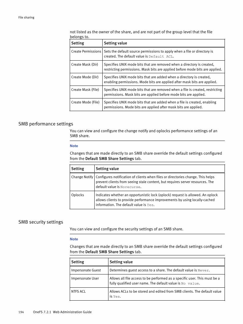
not listed as the owner of the share, and are not part of the group level that the filebelongs to.
Setting Setting value
Create Permissions Sets the default source permissions to apply when a file or directory iscreated. The default value is Default ACL.
Create Mask (Dir) Specifies UNIX mode bits that are removed when a directory is created,restricting permissions. Mask bits are applied before mode bits are applied.
Create Mode (Dir) Specifies UNIX mode bits that are added when a directory is created,enabling permissions. Mode bits are applied after mask bits are applied.
Create Mask (File) Specifies UNIX mode bits that are removed when a file is created, restrictingpermissions. Mask bits are applied before mode bits are applied.
Create Mode (File) Specifies UNIX mode bits that are added when a file is created, enablingpermissions. Mode bits are applied after mask bits are applied.
SMB performance settingsYou can view and configure the change notify and oplocks performance settings of anSMB share.
Note
Changes that are made directly to an SMB share override the default settings configuredfrom the Default SMB Share Settings tab.
Setting Setting value
Change Notify Configures notification of clients when files or directories change. This helpsprevent clients from seeing stale content, but requires server resources. Thedefault value is Norecurse.
Oplocks Indicates whether an opportunistic lock (oplock) request is allowed. An oplockallows clients to provide performance improvements by using locally-cachedinformation. The default value is Yes.
SMB security settingsYou can view and configure the security settings of an SMB share.
Note
Changes that are made directly to an SMB share override the default settings configuredfrom the Default SMB Share Settings tab.
Setting Setting value
Impersonate Guest Determines guest access to a share. The default value is Never.
Impersonate User Allows all file access to be performed as a specific user. This must be afully qualified user name. The default value is No value.
NTFS ACL Allows ACLs to be stored and edited from SMB clients. The default valueis Yes.
File sharing
194 OneFS 7.2.1 Web Administration Guide
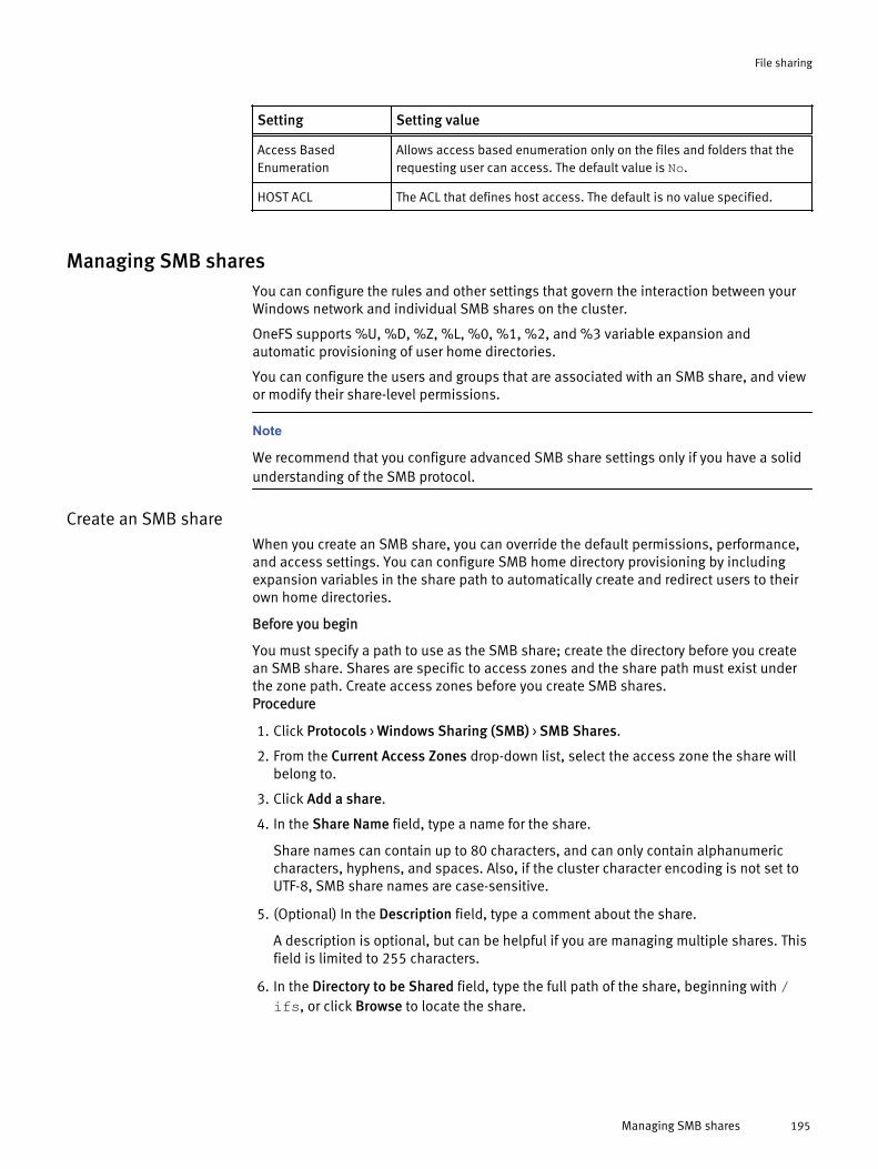
Setting Setting value
Access BasedEnumeration
Allows access based enumeration only on the files and folders that therequesting user can access. The default value is No.
HOST ACL The ACL that defines host access. The default is no value specified.
Managing SMB sharesYou can configure the rules and other settings that govern the interaction between yourWindows network and individual SMB shares on the cluster.
OneFS supports %U, %D, %Z, %L, %0, %1, %2, and %3 variable expansion andautomatic provisioning of user home directories.
You can configure the users and groups that are associated with an SMB share, and viewor modify their share-level permissions.
Note
We recommend that you configure advanced SMB share settings only if you have a solidunderstanding of the SMB protocol.
Create an SMB shareWhen you create an SMB share, you can override the default permissions, performance,and access settings. You can configure SMB home directory provisioning by includingexpansion variables in the share path to automatically create and redirect users to theirown home directories.
Before you begin
You must specify a path to use as the SMB share; create the directory before you createan SMB share. Shares are specific to access zones and the share path must exist underthe zone path. Create access zones before you create SMB shares.Procedure
1. Click Protocols > Windows Sharing (SMB) > SMB Shares.
2. From the Current Access Zones drop-down list, select the access zone the share willbelong to.
3. Click Add a share.
4. In the Share Name field, type a name for the share.
Share names can contain up to 80 characters, and can only contain alphanumericcharacters, hyphens, and spaces. Also, if the cluster character encoding is not set toUTF-8, SMB share names are case-sensitive.
5. (Optional) In the Description field, type a comment about the share.
A description is optional, but can be helpful if you are managing multiple shares. Thisfield is limited to 255 characters.
6. In the Directory to be Shared field, type the full path of the share, beginning with /ifs, or click Browse to locate the share.
File sharing
Managing SMB shares 195

Note
You can specify one or more of the following variables in the directory path but youmust select the Allow Variable Expansion check box or the string is interpretedliterally by the system.
Variable Expansion
%D NetBIOS domain name.
%U User name—for example, user_001.
%Z Zone name—for example, System.
%L Host name of the cluster, normalized to lowercase.
%0 First character of the user name.
%1 Second character of the user name.
%2 Third character of the user name.
For example, if a user is in a domain named DOMAIN and has a username of user_1,the path /ifs/home/%D/%U expands to /ifs/home/DOMAIN/user_1.
7. Apply the initial ACL settings for the directory. You can modify these settings later.
l To apply a default ACL to the shared directory, click Apply Windows default ACLs.
Note
If the Auto-Create Directories setting is enabled, OneFS creates an ACL with theequivalent of UNIX 700 mode bit permissions for any directory that is createdautomatically.
l To maintain the existing permissions on the shared directory, click Do not changeexisting permissions.
8. (Optional) Configure home directory provisioning settings.
l To expand path variables such as %U in the share directory path, select AllowVariable Expansion.
l To automatically create home directories when users access the share for the firsttime, select Auto-Create Directories. This option is available only if the AllowVariable Expansion option is enabled.
9. (Optional) Apply advanced SMB share settings if needed.
10. Click Create.
After you finish
The default permissions configuration is read-only access for the well-known Everyoneaccount. Modify the Users and Groups section settings to allow users to write to theshare.
File sharing
196 OneFS 7.2.1 Web Administration Guide
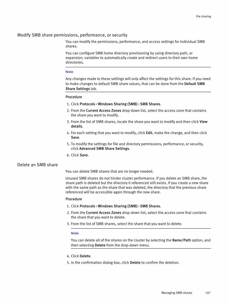
Modify SMB share permissions, performance, or securityYou can modify the permissions, performance, and access settings for individual SMBshares.
You can configure SMB home directory provisioning by using directory path, orexpansion, variables to automatically create and redirect users to their own homedirectories.
Note
Any changes made to these settings will only affect the settings for this share. If you needto make changes to default SMB share values, that can be done from the Default SMBShare Settings tab.
Procedure
1. Click Protocols > Windows Sharing (SMB) > SMB Shares.
2. From the Current Access Zones drop-down list, select the access zone that containsthe share you want to modify.
3. From the list of SMB shares, locate the share you want to modify and then click Viewdetails.
4. For each setting that you want to modify, click Edit, make the change, and then clickSave.
5. To modify the settings for file and directory permissions, performance, or security,click Advanced SMB Share Settings.
6. Click Save.
Delete an SMB shareYou can delete SMB shares that are no longer needed.
Unused SMB shares do not hinder cluster performance. If you delete an SMB share, theshare path is deleted but the directory it referenced still exists. If you create a new sharewith the same path as the share that was deleted, the directory that the previous sharereferenced will be accessible again through the new share.
Procedure
1. Click Protocols > Windows Sharing (SMB) > SMB Shares.
2. From the Current Access Zones drop-down list, select the access zone that containsthe share that you want to delete.
3. From the list of SMB shares, select the share that you want to delete.
Note
You can delete all of the shares on the cluster by selecting the Name/Path option, andthen selecting Delete from the drop-down menu.
4. Click Delete.
5. In the confirmation dialog box, click Delete to confirm the deletion.
File sharing
Managing SMB shares 197

Limit access to /ifs share for the Everyone accountBy default, the /ifs root directory is configured as an SMB share in the System accesszone. We recommend that you restrict the Everyone account of this share to read-onlyaccess.
Procedure
1. Click Protocols > Windows Sharing (SMB) > SMB Shares.
2. From the Current Access Zone drop-down list, select System.
3. Click View details for the /ifs share.
4. Click Edit next to the Users & Groups option.
5. In the User/Group Accounts list, click Edit next to the Everyone account.
6. Click Specify Permission Level and then select the Read option.
The Full Control and Read-Write options should not be selected.
7. Click Save.
Configure anonymous access to a single SMB shareYou can configure anonymous access to data stored on a single share through Guest userimpersonation.
Procedure
1. Click Access > Membership & Roles > Users.
2. From the Current Access Zone list, select the access zone that contains the share youwant to allow anonymous access.
3. From the Users list, select Local.
a. Click View details for the Guest account.
b. Next to the Enable Account area, click Edit.
c. Select the Enable Account check box, and then click Save.
4. Click Protocols > Windows Sharing (SMB) > SMB Shares.
5. Click View details next to the share you to allow anonymous access.
6. Click Advanced SMB Share Settings, and then click Security Settings.
7. From the Impersonate Guest drop-down list, select Use Custom.
8. At the Confirm Default Override dialog box, click Continue.
A second drop-down list is displayed.
9. Select Always from the drop-down list, and then click Save.
Configure anonymous access to all SMB shares in an access zoneYou can configure anonymous access to data stored in an access zone through Guestuser impersonation.
Procedure
1. Click Access > Membership & Roles > Users.
2. From the Current Access Zone list, select the access zone you want to allowanonymous access.
File sharing
198 OneFS 7.2.1 Web Administration Guide
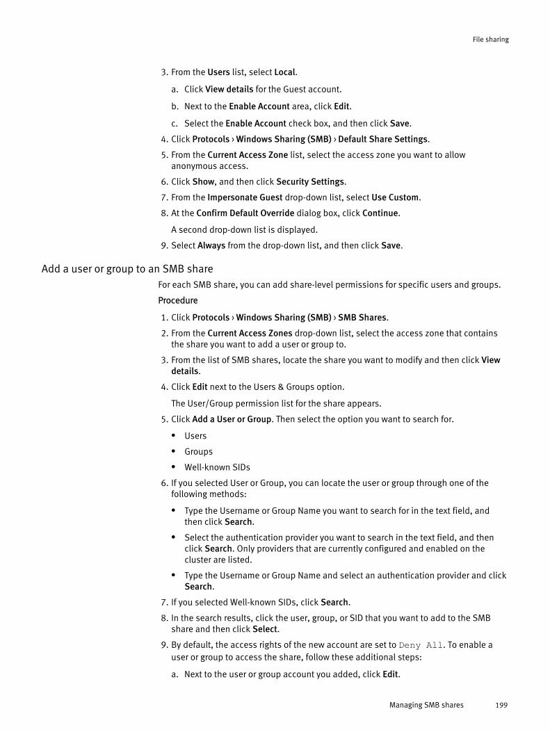
3. From the Users list, select Local.
a. Click View details for the Guest account.
b. Next to the Enable Account area, click Edit.
c. Select the Enable Account check box, and then click Save.
4. Click Protocols > Windows Sharing (SMB) > Default Share Settings.
5. From the Current Access Zone list, select the access zone you want to allowanonymous access.
6. Click Show, and then click Security Settings.
7. From the Impersonate Guest drop-down list, select Use Custom.
8. At the Confirm Default Override dialog box, click Continue.
A second drop-down list is displayed.
9. Select Always from the drop-down list, and then click Save.
Add a user or group to an SMB shareFor each SMB share, you can add share-level permissions for specific users and groups.
Procedure
1. Click Protocols > Windows Sharing (SMB) > SMB Shares.
2. From the Current Access Zones drop-down list, select the access zone that containsthe share you want to add a user or group to.
3. From the list of SMB shares, locate the share you want to modify and then click Viewdetails.
4. Click Edit next to the Users & Groups option.
The User/Group permission list for the share appears.
5. Click Add a User or Group. Then select the option you want to search for.
l Users
l Groups
l Well-known SIDs
6. If you selected User or Group, you can locate the user or group through one of thefollowing methods:
l Type the Username or Group Name you want to search for in the text field, andthen click Search.
l Select the authentication provider you want to search in the text field, and thenclick Search. Only providers that are currently configured and enabled on thecluster are listed.
l Type the Username or Group Name and select an authentication provider and clickSearch.
7. If you selected Well-known SIDs, click Search.
8. In the search results, click the user, group, or SID that you want to add to the SMBshare and then click Select.
9. By default, the access rights of the new account are set to Deny All. To enable auser or group to access the share, follow these additional steps:
a. Next to the user or group account you added, click Edit.
File sharing
Managing SMB shares 199

b. Select Run as Root or select Specify Permission Level and then select one or moreof the following permission levels: Full Control, Read-Write, and Read.
10. Click Save.
Configure multi-protocol home directory accessFor users who will access this share through FTP or SSH, you can make sure that theirhome directory path is the same whether they connect through SMB or they log inthrough FTP or SSH.
This command directs the SMB share to use the home directory template that is specifiedin the user's authentication provider. This procedure is available only through thecommand-line interface.
Procedure
1. Establish an SSH connection to any node in the cluster.
2. Run the following command, where <homedir_share> is the name of the SMB share:
isi smb share modify <homedir_share> --path=""
NFSOneFS provides an NFS server so you can share files on your cluster with NFS clients thatadhere to the RFC1813 (NFSv3) and RFC3530 (NFSv4) specifications.
In OneFS, the NFS server is fully optimized as a multi-threaded service running in userspace instead of the kernel. This architecture load balances the NFS service across allnodes of the cluster, providing the stability and scalability necessary to manage up tothousands of connections across multiple NFS clients.
NFS mounts execute and refresh quickly, and the server constantly monitors fluctuatingdemands on NFS services and makes adjustments across all nodes to ensure continuous,reliable performance. Using a built-in process scheduler, OneFS helps ensure fairallocation of node resources so that no client can seize more than its fair share of NFSservices.
The NFS server also supports access zones defined in OneFS, so that clients can accessonly the exports appropriate to their zone. For example, if NFS exports are specified forZone 2, only clients assigned to Zone 2 can access these exports.
To simplify client connections, especially for exports with large path names, the NFSserver also supports aliases, which are shortcuts to mount points that clients can specifydirectly.
For secure NFS file sharing, OneFS supports NIS and LDAP authentication providers.
NFS exportsYou can manage individual NFS export rules that define mount-points (paths) available toNFS clients and how the server should perform with these clients.
In OneFS, you can create, delete, list, view, modify, and reload NFS exports.
NFS export rules are zone-aware. Each export is associated with a zone, can only bemounted by clients on that zone, and can only expose paths below the zone root. Bydefault, any export command applies to the client's current zone.
Each rule must have at least one path (mount-point), and can include additional paths.You can also specify that all subdirectories of the given path or paths are mountable.
File sharing
200 OneFS 7.2.1 Web Administration Guide
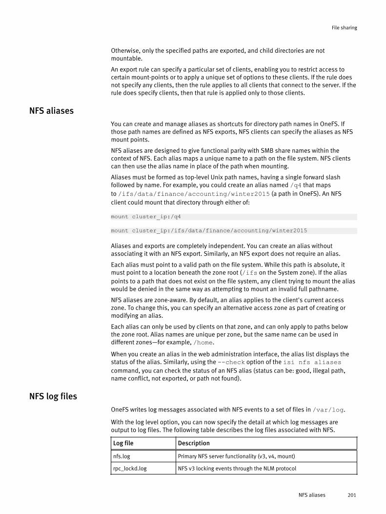
Otherwise, only the specified paths are exported, and child directories are notmountable.
An export rule can specify a particular set of clients, enabling you to restrict access tocertain mount-points or to apply a unique set of options to these clients. If the rule doesnot specify any clients, then the rule applies to all clients that connect to the server. If therule does specify clients, then that rule is applied only to those clients.
NFS aliasesYou can create and manage aliases as shortcuts for directory path names in OneFS. Ifthose path names are defined as NFS exports, NFS clients can specify the aliases as NFSmount points.
NFS aliases are designed to give functional parity with SMB share names within thecontext of NFS. Each alias maps a unique name to a path on the file system. NFS clientscan then use the alias name in place of the path when mounting.
Aliases must be formed as top-level Unix path names, having a single forward slashfollowed by name. For example, you could create an alias named /q4 that mapsto /ifs/data/finance/accounting/winter2015 (a path in OneFS). An NFSclient could mount that directory through either of:
mount cluster_ip:/q4
mount cluster_ip:/ifs/data/finance/accounting/winter2015
Aliases and exports are completely independent. You can create an alias withoutassociating it with an NFS export. Similarly, an NFS export does not require an alias.
Each alias must point to a valid path on the file system. While this path is absolute, itmust point to a location beneath the zone root (/ifs on the System zone). If the aliaspoints to a path that does not exist on the file system, any client trying to mount the aliaswould be denied in the same way as attempting to mount an invalid full pathname.
NFS aliases are zone-aware. By default, an alias applies to the client's current accesszone. To change this, you can specify an alternative access zone as part of creating ormodifying an alias.
Each alias can only be used by clients on that zone, and can only apply to paths belowthe zone root. Alias names are unique per zone, but the same name can be used indifferent zones—for example, /home.
When you create an alias in the web administration interface, the alias list displays thestatus of the alias. Similarly, using the --check option of the isi nfs aliasescommand, you can check the status of an NFS alias (status can be: good, illegal path,name conflict, not exported, or path not found).
NFS log filesOneFS writes log messages associated with NFS events to a set of files in /var/log.
With the log level option, you can now specify the detail at which log messages areoutput to log files. The following table describes the log files associated with NFS.
Log file Description
nfs.log Primary NFS server functionality (v3, v4, mount)
rpc_lockd.log NFS v3 locking events through the NLM protocol
File sharing
NFS aliases 201
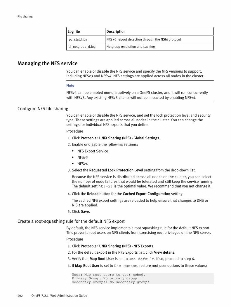
Log file Description
rpc_statd.log NFS v3 reboot detection through the NSM protocol
isi_netgroup_d.log Netgroup resolution and caching
Managing the NFS serviceYou can enable or disable the NFS service and specify the NFS versions to support,including NFSv3 and NFSv4. NFS settings are applied across all nodes in the cluster.
Note
NFSv4 can be enabled non-disruptively on a OneFS cluster, and it will run concurrentlywith NFSv3. Any existing NFSv3 clients will not be impacted by enabling NFSv4.
Configure NFS file sharingYou can enable or disable the NFS service, and set the lock protection level and securitytype. These settings are applied across all nodes in the cluster. You can change thesettings for individual NFS exports that you define.
Procedure
1. Click Protocols > UNIX Sharing (NFS) > Global Settings.
2. Enable or disable the following settings:
l NFS Export Service
l NFSv3
l NFSv4
3. Select the Requested Lock Protection Level setting from the drop-down list.
Because the NFS service is distributed across all nodes on the cluster, you can selectthe number of node failures that would be tolerated and still keep the service running.The default setting [+2] is the optimal value. We recommend that you not change it.
4. Click the Reload button for the Cached Export Configuration setting.
The cached NFS export settings are reloaded to help ensure that changes to DNS orNIS are applied.
5. Click Save.
Create a root-squashing rule for the default NFS exportBy default, the NFS service implements a root-squashing rule for the default NFS export.This prevents root users on NFS clients from exercising root privileges on the NFS server.
Procedure
1. Click Protocols > UNIX Sharing (NFS) > NFS Exports.
2. For the default export in the NFS Exports list, click View details.
3. Verify that Map Root User is set to Use default. If so, proceed to step 6.
4. If Map Root User is set to Use custom, restore root user options to these values:
User: Map root users to user nobodyPrimary Group: No primary groupSecondary Groups: No secondary groups
File sharing
202 OneFS 7.2.1 Web Administration Guide
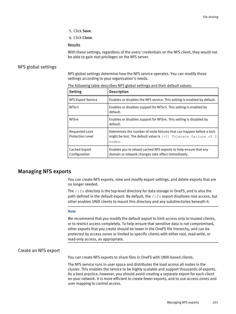
5. Click Save.
6. Click Close.
Results
With these settings, regardless of the users' credentials on the NFS client, they would notbe able to gain root privileges on the NFS server.
NFS global settingsNFS global settings determine how the NFS service operates. You can modify thesesettings according to your organization's needs.
The following table describes NFS global settings and their default values:
Setting Description
NFS Export Service Enables or disables the NFS service. This setting is enabled by default.
NFSv3 Enables or disables support for NFSv3. This setting is enabled bydefault.
NFSv4 Enables or disables support for NFSv4. This setting is disabled bydefault.
Requested LockProtection Level
Determines the number of node failures that can happen before a lockmight be lost. The default value is [+2] Tolerate failure of 2nodes.
Cached ExportConfiguration
Enables you to reload cached NFS exports to help ensure that anydomain or network changes take effect immediately.
Managing NFS exportsYou can create NFS exports, view and modify export settings, and delete exports that areno longer needed.
The /ifs directory is the top-level directory for data storage in OneFS, and is also thepath defined in the default export. By default, the /ifs export disallows root access, butother enables UNIX clients to mount this directory and any subdirectories beneath it.
Note
We recommend that you modify the default export to limit access only to trusted clients,or to restrict access completely. To help ensure that sensitive data is not compromised,other exports that you create should be lower in the OneFS file hierarchy, and can beprotected by access zones or limited to specific clients with either root, read-write, orread-only access, as appropriate.
Create an NFS exportYou can create NFS exports to share files in OneFS with UNIX-based clients.
The NFS service runs in user space and distributes the load across all nodes in thecluster. This enables the service to be highly scalable and support thousands of exports.As a best practice, however, you should avoid creating a separate export for each clienton your network. It is more efficient to create fewer exports, and to use access zones anduser mapping to control access.
File sharing
Managing NFS exports 203
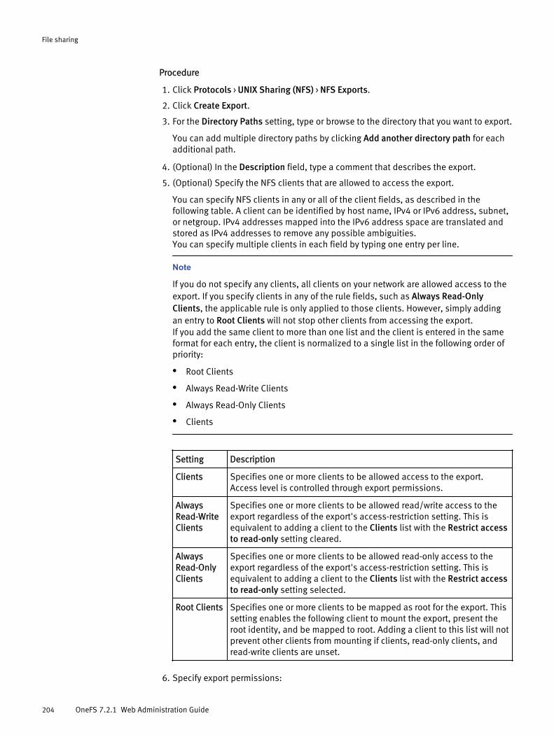
Procedure
1. Click Protocols > UNIX Sharing (NFS) > NFS Exports.
2. Click Create Export.
3. For the Directory Paths setting, type or browse to the directory that you want to export.
You can add multiple directory paths by clicking Add another directory path for eachadditional path.
4. (Optional) In the Description field, type a comment that describes the export.
5. (Optional) Specify the NFS clients that are allowed to access the export.
You can specify NFS clients in any or all of the client fields, as described in thefollowing table. A client can be identified by host name, IPv4 or IPv6 address, subnet,or netgroup. IPv4 addresses mapped into the IPv6 address space are translated andstored as IPv4 addresses to remove any possible ambiguities.You can specify multiple clients in each field by typing one entry per line.
Note
If you do not specify any clients, all clients on your network are allowed access to theexport. If you specify clients in any of the rule fields, such as Always Read-OnlyClients, the applicable rule is only applied to those clients. However, simply addingan entry to Root Clients will not stop other clients from accessing the export.If you add the same client to more than one list and the client is entered in the sameformat for each entry, the client is normalized to a single list in the following order ofpriority:
l Root Clients
l Always Read-Write Clients
l Always Read-Only Clients
l Clients
Setting Description
Clients Specifies one or more clients to be allowed access to the export.Access level is controlled through export permissions.
AlwaysRead-WriteClients
Specifies one or more clients to be allowed read/write access to theexport regardless of the export's access-restriction setting. This isequivalent to adding a client to the Clients list with the Restrict accessto read-only setting cleared.
AlwaysRead-OnlyClients
Specifies one or more clients to be allowed read-only access to theexport regardless of the export's access-restriction setting. This isequivalent to adding a client to the Clients list with the Restrict accessto read-only setting selected.
Root Clients Specifies one or more clients to be mapped as root for the export. Thissetting enables the following client to mount the export, present theroot identity, and be mapped to root. Adding a client to this list will notprevent other clients from mounting if clients, read-only clients, andread-write clients are unset.
6. Specify export permissions:
File sharing
204 OneFS 7.2.1 Web Administration Guide

l Restrict actions to read-only.
l Enable mount access to subdirectories. Allow subdirectories below the path(s) tobe mounted.
7. Specify user/group mappings.
If you select the Use custom option, you can limit access by mapping root users or allusers to a specific user and group ID. For root squash, map root users to the username nobody.
8. Specify security flavor(s).
If you select the Use custom option, you can select one or more of the followingsecurity types:
l UNIX (system)
l Kerberos5
l Kerberos5 Integrity
l Kerberos5 Privacy
9. Click Show Extra Options to configure advanced NFS export settings.
We recommend that you do not change advanced settings unless it is necessary andyou fully understand the consequences of these changes.
10. Click Save.
Results
The new NFS export is created and shown at the top of the NFS Exports list.
Modify an NFS exportYou can modify the settings for an existing NFS export. In some cases, modifying an NFSexport could invalidate existing NFS client connections.
Procedure
1. Select Protocols > UNIX Sharing (NFS) > NFS Exports.
2. In the NFS Exports list, click View details for the export that you want to modify.
3. For each setting that you want to modify, click Edit, make the change, and then clickSave.
4. Click Close.
5. Click Hide details to redisplay the NFS Exports list.
Delete an NFS exportYou can delete unneeded NFS exports. Any current NFS client connections to theseexports become invalid.
Note
You can delete all the exports on a cluster at once. Click the Export ID/Path check box atthe top of the NFS Exports list, and then select Delete from the drop-down list to the right.
Procedure
1. Select Protocols > UNIX Sharing (NFS) > NFS Exports.
2. In the NFS Exports list, click the check box to the left of the export that you want todelete.
File sharing
Managing NFS exports 205
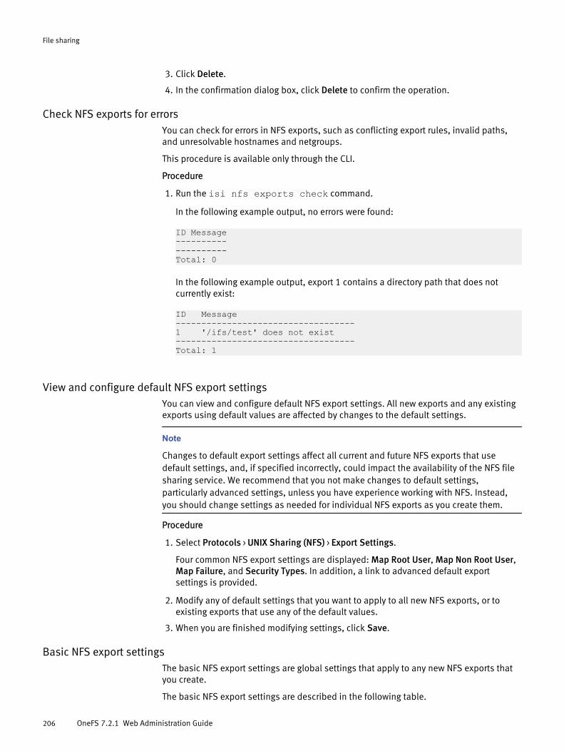
3. Click Delete.
4. In the confirmation dialog box, click Delete to confirm the operation.
Check NFS exports for errorsYou can check for errors in NFS exports, such as conflicting export rules, invalid paths,and unresolvable hostnames and netgroups.
This procedure is available only through the CLI.
Procedure
1. Run the isi nfs exports check command.
In the following example output, no errors were found:
ID Message--------------------Total: 0
In the following example output, export 1 contains a directory path that does notcurrently exist:
ID Message-----------------------------------1 '/ifs/test' does not exist-----------------------------------Total: 1
View and configure default NFS export settingsYou can view and configure default NFS export settings. All new exports and any existingexports using default values are affected by changes to the default settings.
Note
Changes to default export settings affect all current and future NFS exports that usedefault settings, and, if specified incorrectly, could impact the availability of the NFS filesharing service. We recommend that you not make changes to default settings,particularly advanced settings, unless you have experience working with NFS. Instead,you should change settings as needed for individual NFS exports as you create them.
Procedure
1. Select Protocols > UNIX Sharing (NFS) > Export Settings.
Four common NFS export settings are displayed: Map Root User, Map Non Root User,Map Failure, and Security Types. In addition, a link to advanced default exportsettings is provided.
2. Modify any of default settings that you want to apply to all new NFS exports, or toexisting exports that use any of the default values.
3. When you are finished modifying settings, click Save.
Basic NFS export settingsThe basic NFS export settings are global settings that apply to any new NFS exports thatyou create.
The basic NFS export settings are described in the following table.
File sharing
206 OneFS 7.2.1 Web Administration Guide
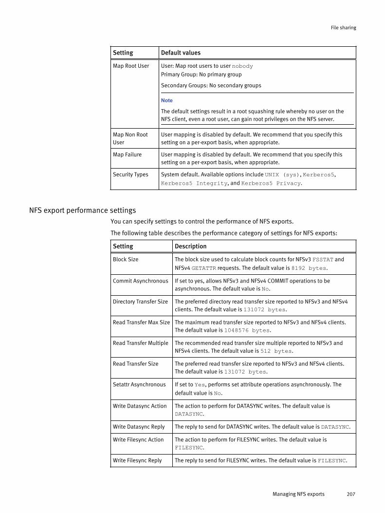
Setting Default values
Map Root User User: Map root users to user nobodyPrimary Group: No primary group
Secondary Groups: No secondary groups
Note
The default settings result in a root squashing rule whereby no user on theNFS client, even a root user, can gain root privileges on the NFS server.
Map Non RootUser
User mapping is disabled by default. We recommend that you specify thissetting on a per-export basis, when appropriate.
Map Failure User mapping is disabled by default. We recommend that you specify thissetting on a per-export basis, when appropriate.
Security Types System default. Available options include UNIX (sys), Kerberos5,
Kerberos5 Integrity, and Kerberos5 Privacy.
NFS export performance settingsYou can specify settings to control the performance of NFS exports.
The following table describes the performance category of settings for NFS exports:
Setting Description
Block Size The block size used to calculate block counts for NFSv3 FSSTAT and
NFSv4 GETATTR requests. The default value is 8192 bytes.
Commit Asynchronous If set to yes, allows NFSv3 and NFSv4 COMMIT operations to beasynchronous. The default value is No.
Directory Transfer Size The preferred directory read transfer size reported to NFSv3 and NFSv4clients. The default value is 131072 bytes.
Read Transfer Max Size The maximum read transfer size reported to NFSv3 and NFSv4 clients.The default value is 1048576 bytes.
Read Transfer Multiple The recommended read transfer size multiple reported to NFSv3 andNFSv4 clients. The default value is 512 bytes.
Read Transfer Size The preferred read transfer size reported to NFSv3 and NFSv4 clients.The default value is 131072 bytes.
Setattr Asynchronous If set to Yes, performs set attribute operations asynchronously. The
default value is No.
Write Datasync Action The action to perform for DATASYNC writes. The default value isDATASYNC.
Write Datasync Reply The reply to send for DATASYNC writes. The default value is DATASYNC.
Write Filesync Action The action to perform for FILESYNC writes. The default value isFILESYNC.
Write Filesync Reply The reply to send for FILESYNC writes. The default value is FILESYNC.
File sharing
Managing NFS exports 207

Setting Description
Write Transfer Max Size The maximum write transfer size reported to NFSv3 and NFSv4 clients.The default value is 1048576 bytes.
Write Transfer Multiple The recommended write transfer size reported to NFSv3 and NFSv4clients. The default value is 512 bytes.
Write Transfer Size The preferred write transfer size reported to NFSv3 and NFSv4 clients.The default value is 524288.
Write Unstable Action The action to perform for UNSTABLE writes. The default value isUNSTABLE.
Write Unstable Reply The reply to send for UNSTABLE writes. The default value is UNSTABLE.
NFS export client compatibility settingsThe NFS export client compatibility settings affect the customization of NFS exports.
These settings are described in the following table.
Setting Setting value
Max File Size Specifies the maximum file size to allow. This setting is advisory in natureand is returned to the client in a reply to an NFSv3 FSINFO or NFSv4 GETATTRrequest. The default value is 9223372036854776000 bytes.
Readdirplus Enable Enables the use of NFSv3 readdirplus service whereby a client can send arequest and received extended information about the directory and files inthe export. The default is Yes.
Return 32 bit FileIDs
Specifies return 32-bit file IDs to the client. The default is No.
NFS export behavior settingsThe NFS export behavior settings control whether NFS clients can perform certainfunctions on the NFS server, such as setting the time.
The NFS export behavior settings are described in the following table.
Setting Description
Can Set Time When this setting is enabled, OneFS allows the NFS client to set various timeattributes on the NFS server. The default value is Yes.
Encoding Overrides the general encoding settings the cluster has for the export. Thedefault value is DEFAULT.
Map Lookup UID Looks up incoming user identifiers (UIDs) in the local authentication database.The default value is No.
Symlinks Informs the NFS client that the file system supports symbolic link file types. Thedefault value is Yes.
Time Delta Sets the server clock granularity. The default value is 1e-9 seconds(0.000000001 second).
File sharing
208 OneFS 7.2.1 Web Administration Guide

Managing NFS aliasesYou can create NFS aliases to simplify exports that clients connect to. An NFS alias mapsan absolute directory path to a simple directory path.
For example, suppose you created an NFS export to /ifs/data/hq/home/archive/first-quarter/finance. You could create the alias /finance1 to map to thatdirectory path.
NFS aliases can be created in any access zone, including the System zone.
Create an NFS aliasYou can create an NFS alias to map a long directory path to a simple pathname.
Aliases must be formed as a simple Unix-style directory path, for example, /home.
Procedure
1. Select Protocols > UNIX Sharing (NFS).
The UNIX Sharing (NFS) page is displayed with four tabs across the top.
2. Click NFS Aliases.
The NFS Aliases list appears, displaying at minimum the current zone's NFS root alias.Any other aliases previously created for the current zone are also listed.
3. Click Create an NFS Alias.
4. In the Create an NFS Alias dialog box, enter a name for the alias.
The alias name must be formed as a simple UNIX-style path with one element, forexample, /home.
5. Enter the full path that the alias is to be associated with.
If you have set up access zones in OneFS, the full path must begin with the root of thecurrent access zone.
6. Click Create Alias.
The Create an NFS Alias dialog box closes.
Results
The name, status, and path of the new alias are shown at the top of the NFS Aliases list.
Modify an NFS aliasYou can modify an NFS alias.
Procedure
1. Select Protocols > UNIX Sharing (NFS).
The UNIX Sharing (NFS) page is displayed with four tabs across the top.
2. Click NFS Aliases.
The NFS Aliases list appears, displaying all aliases for the current access zone.
3. Next to the alias that you intend to modify, click View/Edit.
4. In the View NFS Alias Details dialog box, click Edit Alias.
5. Modify either or both the alias name and the path that the alias represents.
The alias name must be formed as a simple UNIX-style path with one element, forexample, /home. The path must begin with the root of the current access zone. If you
File sharing
Managing NFS aliases 209
are unsure of the pathname, you can click Browse to navigate to the pathname inOneFS.
6. When you are finished modifying the alias, click Save Changes.
The View NFS Alias Details dialog box is displayed, and a message at the top of thedialog box indicates the operation was successful.
7. Click Close.
The View NFS Alias Details dialog box closes.
Results
The modified alias name, status, and path are shown in the NFS Aliases list.
Delete an NFS aliasYou can delete an NFS alias.
If an NFS alias is mapped to an NFS export, deleting the alias can disconnect clients thatused the alias to mount the export.
Procedure
1. Select Protocols > UNIX Sharing (NFS).
The UNIX Sharing (NFS) page is displayed with four tabs across the top.
2. Click NFS Aliases.
The NFS Aliases list appears, displaying all aliases created for the current accesszone.
3. Next to the alias that you intend to delete, select More> Delete Alias.
A Confirm Delete dialog box appears.
4. Click Delete.
The alias is removed from the NFS Aliases list.
List NFS aliasesYou can view a list of NFS aliases that have already been defined.
Procedure
1. Select Protocols > UNIX Sharing (NFS).
The UNIX Sharing (NFS) page is displayed with four tabs across the top.
2. Click NFS Aliases.
The NFS Aliases list appears, displaying all aliases for the current access zone. Thenames, states, and paths for all aliases are shown.
View an NFS aliasYou can view the settings of an NFS alias.
Procedure
1. Select Protocols > UNIX Sharing (NFS).
The UNIX Sharing (NFS) page is displayed with four tabs across the top.
2. Click NFS Aliases.
The NFS Aliases list appears, displaying all aliases for the current access zone.
File sharing
210 OneFS 7.2.1 Web Administration Guide

3. Next to the alias that you want to view, click View/Edit.
The View NFS Alias Details dialog box displays the settings associated with the alias.
4. When you are done viewing the alias, click Close.
FTPOneFS includes a secure FTP service called vsftpd, which stands for Very Secure FTPDaemon, that you can configure for standard FTP and FTPS file transfers.
Enable and configure FTP file sharingYou can set the FTP service to allow any node in the cluster to respond to FTP requeststhrough a standard user account.
You can enable the transfer of files between remote FTP servers and enable anonymousFTP service on the root by creating a local user named anonymous or ftp.
When configuring FTP access, make sure that the specified FTP root is the home directoryof the user who logs in. For example, the FTP root for local user jsmith should be ifs/home/jsmith.
Procedure
1. Click Protocols > FTP Settings.
2. Click Enable.
3. Select one or more of the following settings:
Option Description
Server-to-servertransfers
Enables the transfer of files between two remote FTP servers.This setting is disabled by default.
Anonymousaccess
Enables users with "anonymous" or "ftp" as the user name toaccess files and directories without requiring authentication.This setting is disabled by default.
Local access Enables local users to access files and directories with theirlocal user name and password, allowing them to upload filesdirectly through the file system. This setting is enabled bydefault.
4. Click Submit.
HTTP and HTTPSOneFS includes a configurable HTTP service, which is used to request files that are storedon the cluster and to interact with the web administration interface.
OneFS supports both HTTP and its secure variant, HTTPS. Each node in the cluster runs aninstance of the Apache HTTP Server to provide HTTP access. You can configure the HTTPservice to run in different modes.
Both HTTP and HTTPS are supported for file transfer, but only HTTPS is supported forPlatform API calls. The HTTPS-only requirement includes the web administration interface.In addition, OneFS supports a form of the web-based DAV (WebDAV) protocol thatenables users to modify and manage files on remote web servers. OneFS performs
File sharing
FTP 211

distributed authoring, but does not support versioning and does not perform securitychecks. You can enable DAV in the web administration interface.
Enable and configure HTTPYou can configure HTTP and DAV to enable users to edit and manage files collaborativelyacross remote web servers.
This procedure is available only through the web administration interface.
Procedure
1. Click Protocols > HTTP Settings.
2. From the Service options, select one of the following settings:
Option Description
Enable HTTP Allows HTTP access for cluster administration and browsingcontent on the cluster.
Disable HTTP andredirect to the webinterface
Allows only administrative access to the web administrationinterface. This is the default setting.
Disable HTTP entirely Closes the HTTP port used for file access. Users can continueto access the web administration interface by specifying theport number in the URL. The default port is 8080.
3. In the Document root directory field, type or click Browse to navigate to an existingdirectory in /ifs, or click File System Explorer to create a new directory and set itspermissions.
Note
The HTTP server runs as the daemon user and group. To properly enforce accesscontrols, you must grant the daemon user or group read access to all files under thedocument root, and allow the HTTP server to traverse the document root.
4. In the Server hostname field, type the HTTP server name. The server hostname mustbe a fully-qualified, SmartConnect zone name and valid DNS name. The name mustbegin with a letter and contain only letters, numbers, and hyphens (-).
5. In the Administrator email address field, type an email address to display as theprimary contact for issues that occur while serving files.
6. From the Authentication list, select an authentication setting:
Option Description
Off Disables HTTP authentication.
Basic Authentication Only Enables HTTP basic authentication. User credentialsare sent in plain text.
Integrated AuthenticationOnly
Enables HTTP authentication via NTLM, Kerberos, orboth.
Integrated and BasicAuthentication
Enables both basic and integrated authentication.
File sharing
212 OneFS 7.2.1 Web Administration Guide
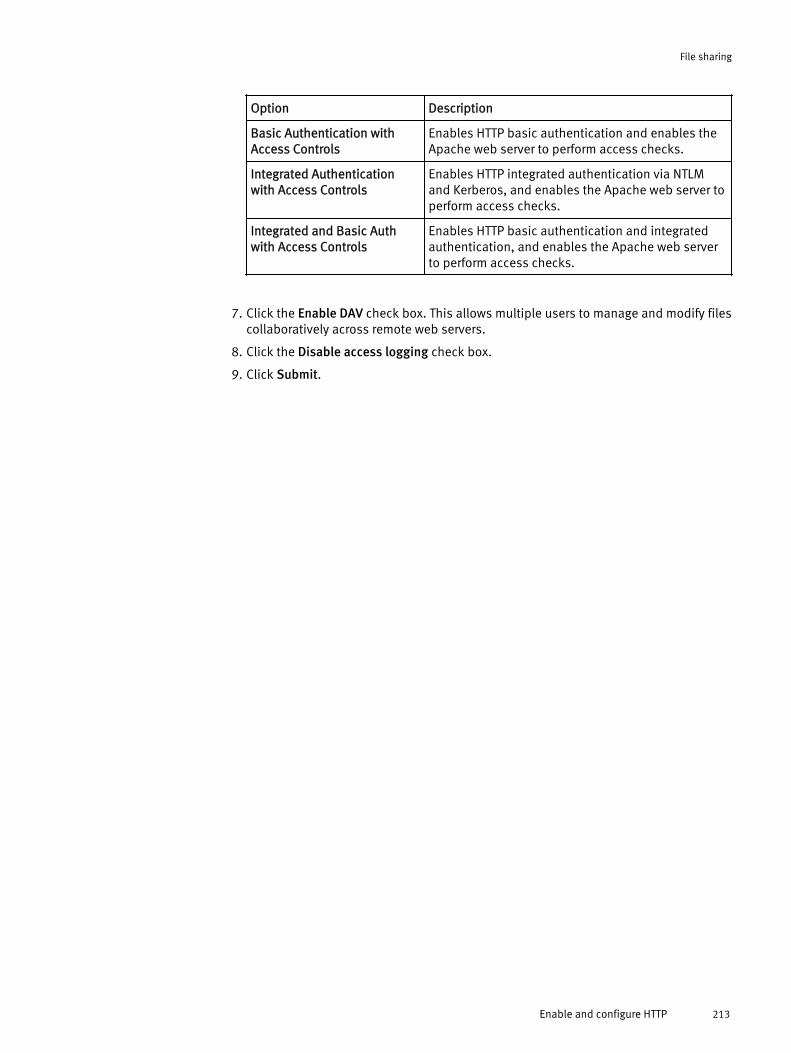
Option Description
Basic Authentication withAccess Controls
Enables HTTP basic authentication and enables theApache web server to perform access checks.
Integrated Authenticationwith Access Controls
Enables HTTP integrated authentication via NTLMand Kerberos, and enables the Apache web server toperform access checks.
Integrated and Basic Authwith Access Controls
Enables HTTP basic authentication and integratedauthentication, and enables the Apache web serverto perform access checks.
7. Click the Enable DAV check box. This allows multiple users to manage and modify filescollaboratively across remote web servers.
8. Click the Disable access logging check box.
9. Click Submit.
File sharing
Enable and configure HTTP 213

File sharing
214 OneFS 7.2.1 Web Administration Guide
CHAPTER 11
Auditing
This section contains the following topics:
l Auditing overview................................................................................................216l Syslog................................................................................................................. 216l Protocol audit events.......................................................................................... 217l Supported event types........................................................................................ 219l Supported audit tools......................................................................................... 219l Enable system configuration auditing..................................................................220l Enable protocol access auditing..........................................................................220l Auditing settings................................................................................................. 221
Auditing 215
Auditing overviewYou can audit system configuration changes and SMB and NFS protocol activity on anEMC Isilon cluster. All audit data is stored and protected in the cluster file system andorganized by audit topics.
When you enable system configuration auditing, no additional configuration is required;all configuration events that are handled by the application programming interface (API)through the command-line interface (CLI) are tracked and recorded in the config audittopic directories.
Auditing can detect many potential sources of data loss, including fraudulent activities,inappropriate entitlements, and unauthorized access attempts. Customers in industriessuch as financial services, health care, life sciences, and media and entertainment, aswell as in governmental agencies, must meet stringent regulatory requirementsdeveloped to protect against these sources of data loss.
You can enable and configure protocol auditing for one or more access zones in a cluster.If you enable protocol auditing for an access zone, file-access events through the SMBand NFS protocol are recorded in the protocol audit topic directories. The protocolaudit log file is consumable by auditing applications that support the EMC Common EventEnabler (CEE). You can specify which events to log in each access zone. For example, youmight want to audit the default set of protocol events in the System access zone butaudit only successful attempts to delete files in a different access zone.
The audit events are logged on the individual nodes where the SMB or NFS client initiatedthe activity. The events are then stored in a binary file under /ifs/.ifsvar/audit/logs. The logs automatically roll over to a new file after the size reaches 1 GB.
SyslogSyslog is a protocol that is used to convey certain event notification messages. The rootuser can configure an Isilon cluster to log audit events and forward them to syslog byusing the syslog forwarder.
By default, all protocol events that occur on a particular node are forwarded tothe /var/log/audit_protocol.log file, regardless of the access zone the eventoriginated from.
Syslog is configured with an identity of audit_protocol, a facility of syslog, and apriority level of info.
Enable syslogBy default, audit event forwarding to syslog is not enabled when auditing is enabled. Toenable this feature, you must configure audit syslog settings through the command lineinterface for zones.
Before you begin
Note
To enable audit event forwarding, you must configure audit syslog settings for eachaccess zone. This procedure is available only through the command-line interface (CLI).
Auditing
216 OneFS 7.2.1 Web Administration Guide
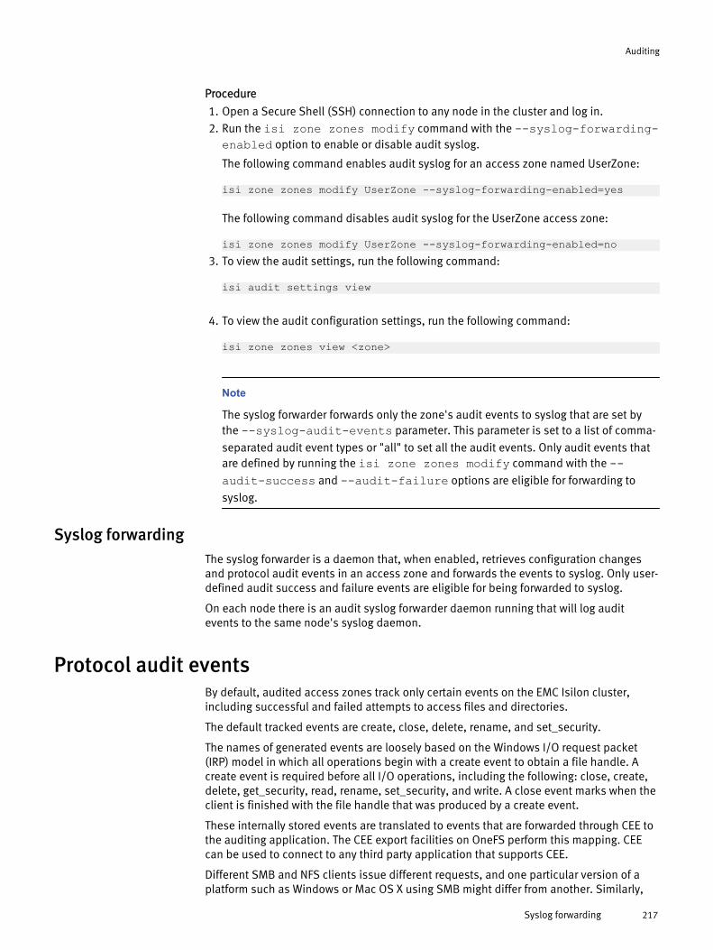
Procedure
1. Open a Secure Shell (SSH) connection to any node in the cluster and log in.
2. Run the isi zone zones modify command with the --syslog-forwarding-enabled option to enable or disable audit syslog.
The following command enables audit syslog for an access zone named UserZone:
isi zone zones modify UserZone --syslog-forwarding-enabled=yes
The following command disables audit syslog for the UserZone access zone:
isi zone zones modify UserZone --syslog-forwarding-enabled=no 3. To view the audit settings, run the following command:
isi audit settings view
4. To view the audit configuration settings, run the following command:
isi zone zones view <zone>
Note
The syslog forwarder forwards only the zone's audit events to syslog that are set bythe --syslog-audit-events parameter. This parameter is set to a list of comma-
separated audit event types or "all" to set all the audit events. Only audit events thatare defined by running the isi zone zones modify command with the --audit-success and --audit-failure options are eligible for forwarding to
syslog.
Syslog forwardingThe syslog forwarder is a daemon that, when enabled, retrieves configuration changesand protocol audit events in an access zone and forwards the events to syslog. Only user-defined audit success and failure events are eligible for being forwarded to syslog.
On each node there is an audit syslog forwarder daemon running that will log auditevents to the same node's syslog daemon.
Protocol audit eventsBy default, audited access zones track only certain events on the EMC Isilon cluster,including successful and failed attempts to access files and directories.
The default tracked events are create, close, delete, rename, and set_security.
The names of generated events are loosely based on the Windows I/O request packet(IRP) model in which all operations begin with a create event to obtain a file handle. Acreate event is required before all I/O operations, including the following: close, create,delete, get_security, read, rename, set_security, and write. A close event marks when theclient is finished with the file handle that was produced by a create event.
These internally stored events are translated to events that are forwarded through CEE tothe auditing application. The CEE export facilities on OneFS perform this mapping. CEEcan be used to connect to any third party application that supports CEE.
Different SMB and NFS clients issue different requests, and one particular version of aplatform such as Windows or Mac OS X using SMB might differ from another. Similarly,
Auditing
Syslog forwarding 217
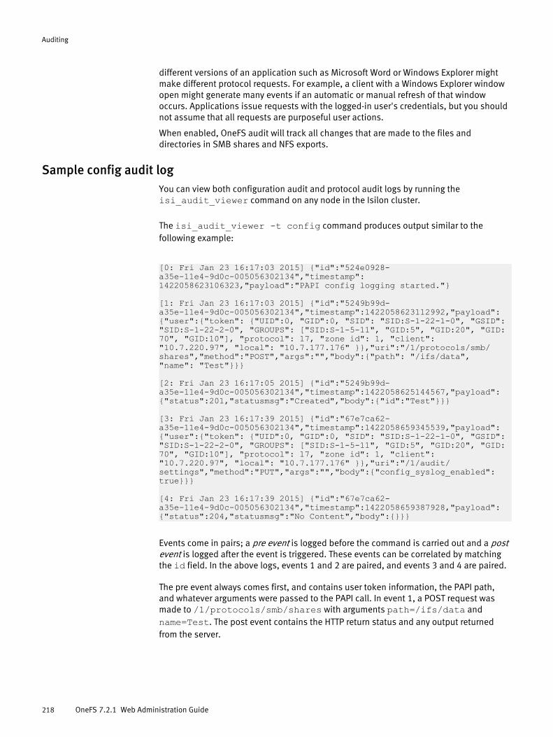
different versions of an application such as Microsoft Word or Windows Explorer mightmake different protocol requests. For example, a client with a Windows Explorer windowopen might generate many events if an automatic or manual refresh of that windowoccurs. Applications issue requests with the logged-in user's credentials, but you shouldnot assume that all requests are purposeful user actions.
When enabled, OneFS audit will track all changes that are made to the files anddirectories in SMB shares and NFS exports.
Sample config audit logYou can view both configuration audit and protocol audit logs by running theisi_audit_viewer command on any node in the Isilon cluster.
The isi_audit_viewer -t config command produces output similar to thefollowing example:
[0: Fri Jan 23 16:17:03 2015] {"id":"524e0928-a35e-11e4-9d0c-005056302134","timestamp":1422058623106323,"payload":"PAPI config logging started."}
[1: Fri Jan 23 16:17:03 2015] {"id":"5249b99d-a35e-11e4-9d0c-005056302134","timestamp":1422058623112992,"payload":{"user":{"token": {"UID":0, "GID":0, "SID": "SID:S-1-22-1-0", "GSID": "SID:S-1-22-2-0", "GROUPS": ["SID:S-1-5-11", "GID:5", "GID:20", "GID:70", "GID:10"], "protocol": 17, "zone id": 1, "client": "10.7.220.97", "local": "10.7.177.176" }},"uri":"/1/protocols/smb/shares","method":"POST","args":"","body":{"path": "/ifs/data", "name": "Test"}}}
[2: Fri Jan 23 16:17:05 2015] {"id":"5249b99d-a35e-11e4-9d0c-005056302134","timestamp":1422058625144567,"payload":{"status":201,"statusmsg":"Created","body":{"id":"Test"}}}
[3: Fri Jan 23 16:17:39 2015] {"id":"67e7ca62-a35e-11e4-9d0c-005056302134","timestamp":1422058659345539,"payload":{"user":{"token": {"UID":0, "GID":0, "SID": "SID:S-1-22-1-0", "GSID": "SID:S-1-22-2-0", "GROUPS": ["SID:S-1-5-11", "GID:5", "GID:20", "GID:70", "GID:10"], "protocol": 17, "zone id": 1, "client": "10.7.220.97", "local": "10.7.177.176" }},"uri":"/1/audit/settings","method":"PUT","args":"","body":{"config_syslog_enabled": true}}}
[4: Fri Jan 23 16:17:39 2015] {"id":"67e7ca62-a35e-11e4-9d0c-005056302134","timestamp":1422058659387928,"payload":{"status":204,"statusmsg":"No Content","body":{}}}
Events come in pairs; a pre event is logged before the command is carried out and a postevent is logged after the event is triggered. These events can be correlated by matchingthe id field. In the above logs, events 1 and 2 are paired, and events 3 and 4 are paired.
The pre event always comes first, and contains user token information, the PAPI path,and whatever arguments were passed to the PAPI call. In event 1, a POST request wasmade to /1/protocols/smb/shares with arguments path=/ifs/data andname=Test. The post event contains the HTTP return status and any output returnedfrom the server.
Auditing
218 OneFS 7.2.1 Web Administration Guide
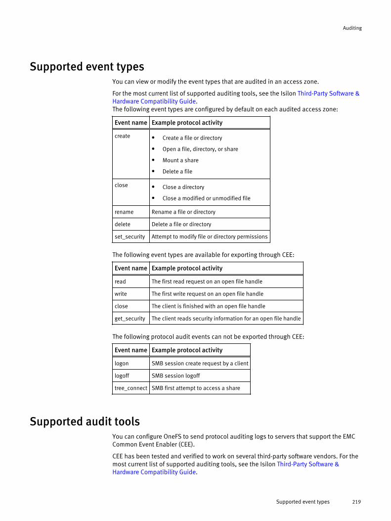
Supported event typesYou can view or modify the event types that are audited in an access zone.
For the most current list of supported auditing tools, see the Isilon Third-Party Software &Hardware Compatibility Guide.The following event types are configured by default on each audited access zone:
Event name Example protocol activity
create l Create a file or directory
l Open a file, directory, or share
l Mount a share
l Delete a file
close l Close a directory
l Close a modified or unmodified file
rename Rename a file or directory
delete Delete a file or directory
set_security Attempt to modify file or directory permissions
The following event types are available for exporting through CEE:
Event name Example protocol activity
read The first read request on an open file handle
write The first write request on an open file handle
close The client is finished with an open file handle
get_security The client reads security information for an open file handle
The following protocol audit events can not be exported through CEE:
Event name Example protocol activity
logon SMB session create request by a client
logoff SMB session logoff
tree_connect SMB first attempt to access a share
Supported audit toolsYou can configure OneFS to send protocol auditing logs to servers that support the EMCCommon Event Enabler (CEE).
CEE has been tested and verified to work on several third-party software vendors. For themost current list of supported auditing tools, see the Isilon Third-Party Software &Hardware Compatibility Guide.
Auditing
Supported event types 219

Note
We recommend that you install and configure third-party auditing applications before youenable the OneFS auditing feature. Otherwise, the large backlog consumed by thisfeature may cause results to not be updated for a considerable amount of time.
Enable system configuration auditingYou can enable or disable the auditing of system configuration changes. No additionalsettings are available.
Note
It is recommended that you install and configure third-party auditing applications beforeyou enable the OneFS auditing feature. Otherwise, the backlog consumed by the tool maybe so large that results may be stale for a prolonged time.
Procedure
1. Click Cluster Management > Auditing.
2. In the Settings area, select the Enable Configuration Change Auditing checkbox.
3. Click Save Changes.
Enable protocol access auditingYou can audit SMB protocol access on a per-access zone basis and optionally forward thegenerated events to the EMC Common Event Enabler (CEE) for export to third-partyproducts.
Note
It is recommended that you install and configure third-party auditing applications beforeyou enable the OneFS auditing feature. Otherwise, the backlog consumed by the tool maybecome so large that results might be stale for a prolonged time.
Procedure
1. Click Cluster Management > Auditing.
2. In the Settings area, select the Enable Protocol Access Auditing checkbox.
3. In the Audited Zones area, click Add Zones.
4. In the Select Zones dialog box, select the checkbox for one or more access zones, andthen click Add Zones.
5. (Optional) In the Event Forwarding area, specify one or more CEE servers to forwardlogged events to.
a. In the CEE Server URIs field, type the URI of each CEE server in the CEE server pool.
The OneFS CEE export service uses round robin load-balancing when exportingevents to multiple CEE servers. Valid URIs start with http:// and include the portnumber and path to the CEE server if necessary—for example, http://example.com:12228/cee.
b. In the Storage Cluster Name field, specify the name of the storage cluster to usewhen forwarding protocol events.
Auditing
220 OneFS 7.2.1 Web Administration Guide

This name value is typically the SmartConnect zone name, but in cases whereSmartConnect is not implemented, the value must match the hostname of thecluster as Varonis recognizes it. If the field is left blank, events from each node arefilled with the node name (clustername + lnn). This setting is required only ifneeded by your third-party audit application.
Note
Although this step is optional, be aware that a backlog of events will accumulateregardless of whether CEE servers have been configured. When configured, CEEforwarding begins with the oldest events in the backlog and moves toward newestevents in a first-in-first-out sequence.
6. Click Save Changes.
Results
The following protocol events, which are the only events supported by VaronisDatAdvantage, are collected for audited access zones by default: create, close,delete, rename, and set_security. You can modify the set of events that areaudited in an access zone by running the isi zone zones modify command in thecommand-line interface. Because each audited event consumes system resources, it isrecommended that you only configure zones for events that are needed by your auditingapplication.
Auditing settingsYou can view or modify basic settings for configuration change auditing and protocolaccess auditing.
Enable Configuration Change AuditingAudits requests that are made through the API for system configuration changes.
Enable Protocol Access AuditingAudits requests that are made through the SMB protocol to access data.
Audited ZonesSpecifies one or more access zones to audit. This setting applies only to protocolaccess auditing.
CEE Server URIsSpecifies one or more CEE server URIs where audit events will be forwarded. TheOneFS CEE export service uses round robin load-balancing when exporting events tomultiple CEE servers. This setting applies only to protocol access auditing.
Storage Cluster NameSpecifies the name of the storage cluster to use when forwarding protocol events—typically, the SmartConnect zone name. This setting is required only if needed byyour third-party audit application.
Auditing
Auditing settings 221

Auditing
222 OneFS 7.2.1 Web Administration Guide
CHAPTER 12
Snapshots
This section contains the following topics:
l Snapshots overview............................................................................................ 224l Data protection with SnapshotIQ.........................................................................224l Snapshot disk-space usage................................................................................ 224l Snapshot schedules............................................................................................225l Snapshot aliases................................................................................................ 225l File and directory restoration...............................................................................225l Best practices for creating snapshots..................................................................226l Best practices for creating snapshot schedules...................................................226l File clones...........................................................................................................227l Snapshot locks................................................................................................... 228l Snapshot reserve................................................................................................ 229l SnapshotIQ license functionality.........................................................................229l Creating snapshots with SnapshotIQ...................................................................229l Managing snapshots .......................................................................................... 234l Restoring snapshot data..................................................................................... 237l Managing snapshot schedules............................................................................239l Managing snapshot aliases.................................................................................240l Managing with snapshot locks............................................................................ 241l Configure SnapshotIQ settings............................................................................ 243l Set the snapshot reserve.....................................................................................245
Snapshots 223

Snapshots overviewA OneFS snapshot is a logical pointer to data that is stored on a cluster at a specific pointin time.
A snapshot references a directory on a cluster, including all data stored in the directoryand its subdirectories. If the data referenced by a snapshot is modified, the snapshotstores a physical copy of the data that was modified. Snapshots are created according touser specifications or are automatically generated by OneFS to facilitate systemoperations.
To create and manage snapshots, you must activate a SnapshotIQ license on the cluster.Some applications must generate snapshots to function but do not require you toactivate a SnapshotIQ license; by default, these snapshots are automatically deletedwhen OneFS no longer needs them. However, if you activate a SnapshotIQ license, youcan retain these snapshots. You can view snapshots generated by other modules withoutactivating a SnapshotIQ license.
You can identify and locate snapshots by name or ID. A snapshot name is specified by auser and assigned to the virtual directory that contains the snapshot. A snapshot ID is anumerical identifier that OneFS automatically assigns to a snapshot.
Data protection with SnapshotIQYou can create snapshots to protect data with the SnapshotIQ software module.Snapshots protect data against accidental deletion and modification by enabling you torestore deleted and modified files. To use SnapshotIQ, you must activate a SnapshotIQlicense on the cluster.
Snapshots are less costly than backing up your data on a separate physical storagedevice in terms of both time and storage consumption. The time required to move data toanother physical device depends on the amount of data being moved, whereassnapshots are always created almost instantaneously regardless of the amount of datareferenced by the snapshot. Also, because snapshots are available locally, end-users canoften restore their data without requiring assistance from a system administrator.Snapshots require less space than a remote backup because unaltered data isreferenced rather than recreated.
Snapshots do not protect against hardware or file-system issues. Snapshots referencedata that is stored on a cluster, so if the data on the cluster becomes unavailable, thesnapshots will also be unavailable. Because of this, it is recommended that you back upyour data to separate physical devices in addition to creating snapshots.
Snapshot disk-space usageThe amount of disk space that a snapshot consumes depends on both the amount ofdata stored by the snapshot and the amount of data the snapshot references from othersnapshots.
Immediately after OneFS creates a snapshot, the snapshot consumes a negligibleamount of disk space. The snapshot does not consume additional disk space unless thedata referenced by the snapshot is modified. If the data that a snapshot references ismodified, the snapshot stores read-only copies of the original data. A snapshotconsumes only the space that is necessary to restore the contents a directory to the stateit was in when the snapshot was taken.
Snapshots
224 OneFS 7.2.1 Web Administration Guide
To reduce disk-space usage, snapshots that reference the same directory reference eachother, with older snapshots referencing newer snapshots. If a file is deleted, and severalsnapshots reference the file, a single snapshot stores a copy the file, and the othersnapshots reference the file from the snapshot that stored the copy. The reported size ofa snapshot reflects only the amount of data stored by the snapshot and does not includethe amount of data referenced by the snapshot.
Because snapshots do not consume a set amount of storage space, there is no available-space requirement for creating a snapshot. The size of a snapshot grows according tohow the data referenced by the snapshot is modified. A cluster cannot contain more than20,000 snapshots.
Snapshot schedulesYou can automatically generate snapshots according to a snapshot schedule.
With snapshot schedules, you can periodically generate snapshots of a directory withouthaving to manually create a snapshot every time. You can also assign an expirationperiod that determines when SnapshotIQ deletes each automatically generatedsnapshot.
Snapshot aliasesA snapshot alias is a logical pointer to a snapshot. If you specify an alias for a snapshotschedule, the alias will always point to the most recent snapshot generated by thatschedule. Assigning a snapshot alias allows you to quickly identify and access the mostrecent snapshot generated according to a snapshot schedule.
If you allow clients to access snapshots through an alias, you can reassign the alias toredirect clients to other snapshots. In addition to assigning snapshot aliases tosnapshots, you can also assign snapshot aliases to the live version of the file system.This can be useful if clients are accessing snapshots through a snapshot alias, and youwant to redirect the clients to the live version of the file system.
File and directory restorationYou can restore the files and directories that are referenced by a snapshot by copyingdata from the snapshot, cloning a file from the snapshot, or reverting the entire snapshot.
Copying a file from a snapshot duplicates the file, which roughly doubles the amount ofstorage space consumed. Even if you delete the original file from the non-snapshotdirectory, the copy of the file remains in the snapshot.
Cloning a file from a snapshot also duplicates the file. However, unlike a copy, whichimmediately consumes additional space on the cluster, a clone does not consume anyadditional space on the cluster unless the clone or cloned file is modified.
Reverting a snapshot replaces the contents of a directory with the data stored in thesnapshot. Before a snapshot is reverted, SnapshotIQ creates a snapshot of the directorythat is being replaced, which enables you to undo the snapshot revert later. Reverting asnapshot can be useful if you want to undo a large number of changes that you made tofiles and directories. If new files or directories have been created in a directory since asnapshot of the directory was created, those files and directories are deleted when thesnapshot is reverted.
Snapshots
Snapshot schedules 225

Note
If you move a directory, you cannot revert snapshots of the directory that were takenbefore the directory was moved.
Best practices for creating snapshotsConsider the following snapshot best practices when working with a large number ofsnapshots.
It is recommended that you do not create more than 1,000 snapshots of a single directoryto avoid performance degradation. If you create a snapshot of a root directory, thatsnapshot counts towards the total number of snapshots for any subdirectories of the rootdirectory. For example, if you create 500 snapshots of /ifs/data and 500 snapshotsof /ifs/data/media, you have created 1000 snapshots of /ifs/data/media.Avoid creating snapshots of directories that are already referenced by other snapshots.
It is recommended that you do not create more than 1000 hard links per file in asnapshot to avoid performance degradation. Always attempt to keep directory paths asshallow as possible. The deeper the depth of directories referenced by snapshots, thegreater the performance degradation.
Creating snapshots of directories higher on a directory tree will increase the amount oftime it takes to modify the data referenced by the snapshot and require more clusterresources to manage the snapshot and the directory. However, creating snapshots ofdirectories lower on directories trees will require more snapshot schedules, which can bedifficult to manage. It is recommended that you do not create snapshots of /ifsor /ifs/data.
You can create up to 20,000 snapshots on a cluster at a time. If you create a largenumber of snapshots, you might not be able to manage snapshots through the OneFSweb administration interface. However, you can manage any number of snapshotsthrough the OneFS command-line interface.
Note
It is recommended that you do not disable the snapshot delete job. Disabling thesnapshot delete job prevents unused disk space from being freed and can also causeperformance degradation.
If the system clock is set to a time zone other than Coordinated Universal Time (UTC),SnapshotIQ modifies snapshot duration periods to match Daylight Savings Time (DST).Upon entering DST, snapshot durations are increased by an hour to adhere to DST; whenexiting DST, snapshot durations are decreased by an hour to adhere to standard time.
Best practices for creating snapshot schedulesSnapshot schedule configurations can be categorized by how they delete snapshots:ordered deletions and unordered deletions.
An ordered deletion is the deletion of the oldest snapshot of a directory. An unordereddeletion is the deletion of a snapshot that is not the oldest snapshot of a directory.Unordered deletions take approximately twice as long to complete and consume morecluster resources than ordered deletions. However, unordered deletions can save spaceby retaining a smaller total number of snapshots.
Snapshots
226 OneFS 7.2.1 Web Administration Guide
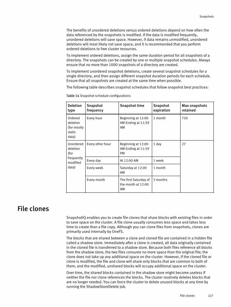
The benefits of unordered deletions versus ordered deletions depend on how often thedata referenced by the snapshots is modified. If the data is modified frequently,unordered deletions will save space. However, if data remains unmodified, unordereddeletions will most likely not save space, and it is recommended that you performordered deletions to free cluster resources.
To implement ordered deletions, assign the same duration period for all snapshots of adirectory. The snapshots can be created by one or multiple snapshot schedules. Alwaysensure that no more than 1000 snapshots of a directory are created.
To implement unordered snapshot deletions, create several snapshot schedules for asingle directory, and then assign different snapshot duration periods for each schedule.Ensure that all snapshots are created at the same time when possible.
The following table describes snapshot schedules that follow snapshot best practices:
Table 14 Snapshot schedule configurations
Deletiontype
Snapshotfrequency
Snapshot time Snapshotexpiration
Max snapshotsretained
Ordereddeletion(for mostlystaticdata)
Every hour Beginning at 12:00AM Ending at 11:59AM
1 month 720
Unordereddeletion(forfrequentlymodifieddata)
Every other hour Beginning at 12:00AM Ending at 11:59PM
1 day 27
Every day At 12:00 AM 1 week
Every week Saturday at 12:00AM
1 month
Every month The first Saturday ofthe month at 12:00AM
3 months
File clonesSnapshotIQ enables you to create file clones that share blocks with existing files in orderto save space on the cluster. A file clone usually consumes less space and takes lesstime to create than a file copy. Although you can clone files from snapshots, clones areprimarily used internally by OneFS.
The blocks that are shared between a clone and cloned file are contained in a hidden filecalled a shadow store. Immediately after a clone is created, all data originally containedin the cloned file is transferred to a shadow store. Because both files reference all blocksfrom the shadow store, the two files consume no more space than the original file; theclone does not take up any additional space on the cluster. However, if the cloned file orclone is modified, the file and clone will share only blocks that are common to both ofthem, and the modified, unshared blocks will occupy additional space on the cluster.
Over time, the shared blocks contained in the shadow store might become useless ifneither the file nor clone references the blocks. The cluster routinely deletes blocks thatare no longer needed. You can force the cluster to delete unused blocks at any time byrunning the ShadowStoreDelete job.
Snapshots
File clones 227
Clones cannot contain alternate data streams (ADS). If you clone a file that containsalternate data streams, the clone will not contain the alternate data streams.
Shadow-store considerationsShadow stores are hidden files that are referenced by cloned and deduplicated files. Filesthat reference shadow stores behave differently than other files.
l Reading shadow-store references might be slower than reading data directly.Specifically, reading non-cached shadow-store references is slower than reading non-cached data. Reading cached shadow-store references takes no more time thanreading cached data.
l When files that reference shadow stores are replicated to another Isilon cluster orbacked up to a Network Data Management Protocol (NDMP) backup device, theshadow stores are not transferred to the target Isilon cluster or backup device. Thefiles are transferred as if they contained the data that they reference from shadowstores. On the target Isilon cluster or backup device, the files consume the sameamount of space as if they had not referenced shadow stores.
l When OneFS creates a shadow store, OneFS assigns the shadow store to a storagepool of a file that references the shadow store. If you delete the storage pool that ashadow store resides on, the shadow store is moved to a pool occupied by anotherfile that references the shadow store.
l OneFS does not delete a shadow-store block immediately after the last reference tothe block is deleted. Instead, OneFS waits until the ShadowStoreDelete job is run todelete the unreferenced block. If a large number of unreferenced blocks exist on thecluster, OneFS might report a negative deduplication savings until theShadowStoreDelete job is run.
l Shadow stores are protected at least as much as the most protected file thatreferences it. For example, if one file that references a shadow store resides in astorage pool with +2 protection and another file that references the shadow storeresides in a storage pool with +3 protection, the shadow store is protected at +3.
l Quotas account for files that reference shadow stores as if the files contained thedata referenced from shadow stores; from the perspective of a quota, shadow-storereferences do not exist. However, if a quota includes data protection overhead, thequota does not account for the data protection overhead of shadow stores.
Snapshot locksA snapshot lock prevents a snapshot from being deleted. If a snapshot has one or morelocks applied to it, the snapshot cannot be deleted and is referred to as a lockedsnapshot. If the duration period of a locked snapshot expires, OneFS will not delete thesnapshot until all locks on the snapshot have been deleted.
OneFS applies snapshot locks to ensure that snapshots generated by OneFS applicationsare not deleted prematurely. For this reason, it is recommended that you do not deletesnapshot locks or modify the duration period of snapshot locks.
A limited number of locks can be applied to a snapshot at a time. If you create snapshotlocks, the limit for a snapshot might be reached, and OneFS could be unable to apply asnapshot lock when necessary. For this reason, it is recommended that you do not createsnapshot locks.
Snapshots
228 OneFS 7.2.1 Web Administration Guide
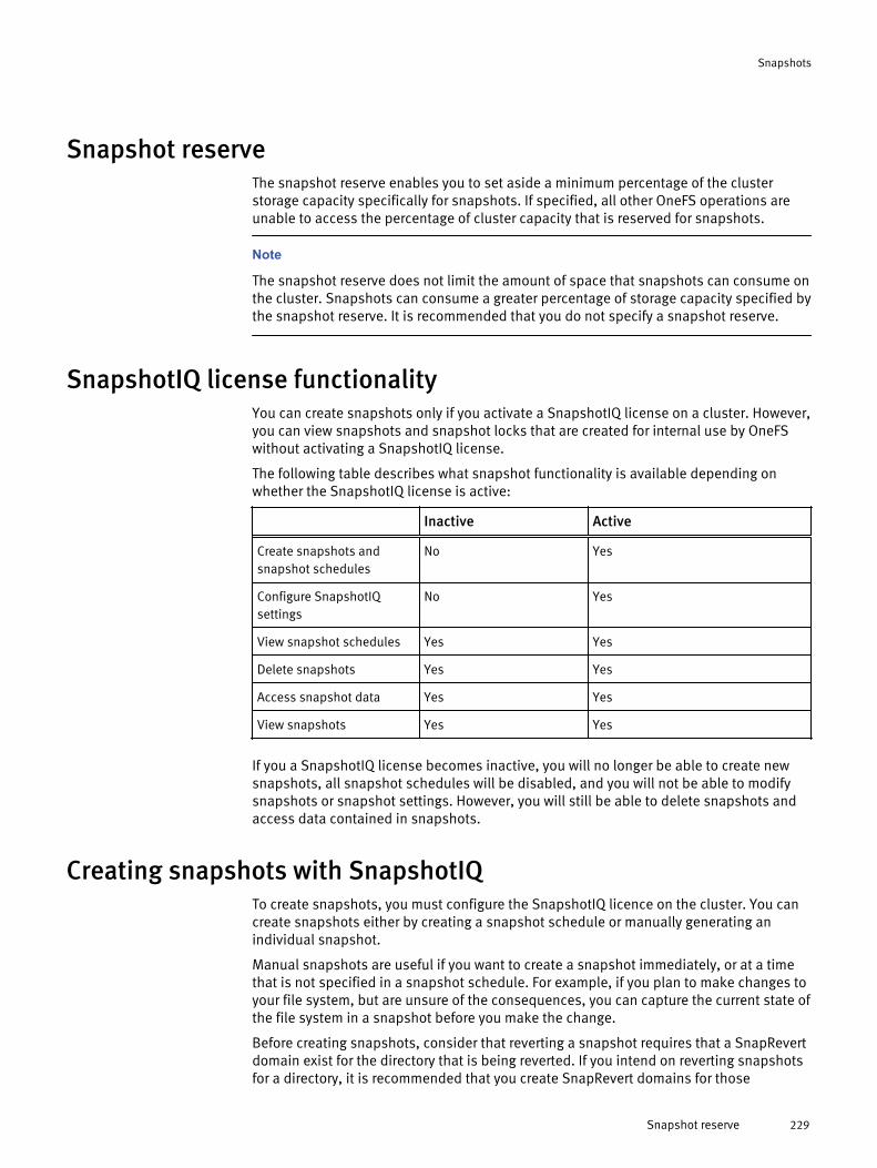
Snapshot reserveThe snapshot reserve enables you to set aside a minimum percentage of the clusterstorage capacity specifically for snapshots. If specified, all other OneFS operations areunable to access the percentage of cluster capacity that is reserved for snapshots.
Note
The snapshot reserve does not limit the amount of space that snapshots can consume onthe cluster. Snapshots can consume a greater percentage of storage capacity specified bythe snapshot reserve. It is recommended that you do not specify a snapshot reserve.
SnapshotIQ license functionalityYou can create snapshots only if you activate a SnapshotIQ license on a cluster. However,you can view snapshots and snapshot locks that are created for internal use by OneFSwithout activating a SnapshotIQ license.
The following table describes what snapshot functionality is available depending onwhether the SnapshotIQ license is active:
Inactive Active
Create snapshots andsnapshot schedules
No Yes
Configure SnapshotIQsettings
No Yes
View snapshot schedules Yes Yes
Delete snapshots Yes Yes
Access snapshot data Yes Yes
View snapshots Yes Yes
If you a SnapshotIQ license becomes inactive, you will no longer be able to create newsnapshots, all snapshot schedules will be disabled, and you will not be able to modifysnapshots or snapshot settings. However, you will still be able to delete snapshots andaccess data contained in snapshots.
Creating snapshots with SnapshotIQTo create snapshots, you must configure the SnapshotIQ licence on the cluster. You cancreate snapshots either by creating a snapshot schedule or manually generating anindividual snapshot.
Manual snapshots are useful if you want to create a snapshot immediately, or at a timethat is not specified in a snapshot schedule. For example, if you plan to make changes toyour file system, but are unsure of the consequences, you can capture the current state ofthe file system in a snapshot before you make the change.
Before creating snapshots, consider that reverting a snapshot requires that a SnapRevertdomain exist for the directory that is being reverted. If you intend on reverting snapshotsfor a directory, it is recommended that you create SnapRevert domains for those
Snapshots
Snapshot reserve 229
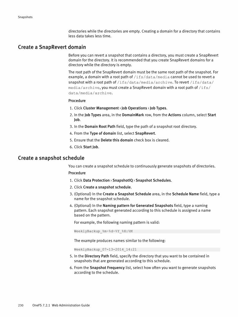
directories while the directories are empty. Creating a domain for a directory that containsless data takes less time.
Create a SnapRevert domainBefore you can revert a snapshot that contains a directory, you must create a SnapRevertdomain for the directory. It is recommended that you create SnapRevert domains for adirectory while the directory is empty.
The root path of the SnapRevert domain must be the same root path of the snapshot. Forexample, a domain with a root path of /ifs/data/media cannot be used to revert asnapshot with a root path of /ifs/data/media/archive. To revert /ifs/data/media/archive, you must create a SnapRevert domain with a root path of /ifs/data/media/archive.
Procedure
1. Click Cluster Management > Job Operations > Job Types.
2. In the Job Types area, in the DomainMark row, from the Actions column, select StartJob.
3. In the Domain Root Path field, type the path of a snapshot root directory.
4. From the Type of domain list, select SnapRevert.
5. Ensure that the Delete this domain check box is cleared.
6. Click Start Job.
Create a snapshot scheduleYou can create a snapshot schedule to continuously generate snapshots of directories.
Procedure
1. Click Data Protection > SnapshotIQ > Snapshot Schedules.
2. Click Create a snapshot schedule.
3. (Optional) In the Create a Snapshot Schedule area, in the Schedule Name field, type aname for the snapshot schedule.
4. (Optional) In the Naming pattern for Generated Snapshots field, type a namingpattern. Each snapshot generated according to this schedule is assigned a namebased on the pattern.
For example, the following naming pattern is valid:
WeeklyBackup_%m-%d-%Y_%H:%M
The example produces names similar to the following:
WeeklyBackup_07-13-2014_14:215. In the Directory Path field, specify the directory that you want to be contained in
snapshots that are generated according to this schedule.
6. From the Snapshot Frequency list, select how often you want to generate snapshotsaccording to the schedule.
Snapshots
230 OneFS 7.2.1 Web Administration Guide
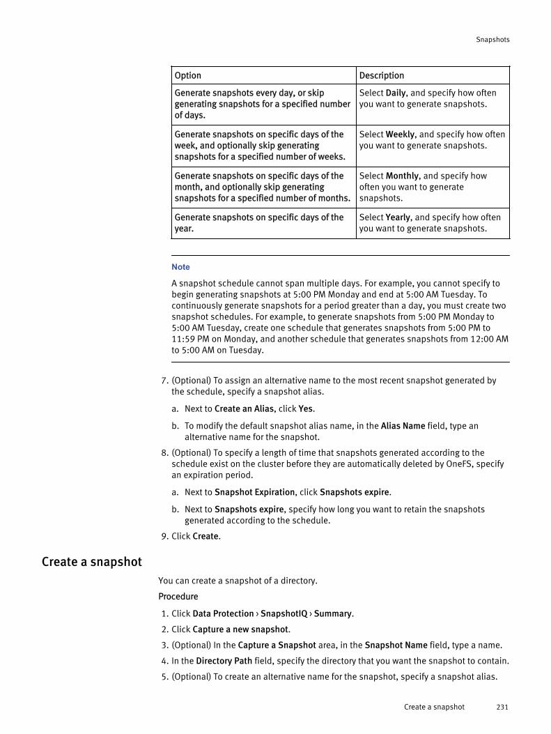
Option Description
Generate snapshots every day, or skipgenerating snapshots for a specified numberof days.
Select Daily, and specify how oftenyou want to generate snapshots.
Generate snapshots on specific days of theweek, and optionally skip generatingsnapshots for a specified number of weeks.
Select Weekly, and specify how oftenyou want to generate snapshots.
Generate snapshots on specific days of themonth, and optionally skip generatingsnapshots for a specified number of months.
Select Monthly, and specify howoften you want to generatesnapshots.
Generate snapshots on specific days of theyear.
Select Yearly, and specify how oftenyou want to generate snapshots.
Note
A snapshot schedule cannot span multiple days. For example, you cannot specify tobegin generating snapshots at 5:00 PM Monday and end at 5:00 AM Tuesday. Tocontinuously generate snapshots for a period greater than a day, you must create twosnapshot schedules. For example, to generate snapshots from 5:00 PM Monday to5:00 AM Tuesday, create one schedule that generates snapshots from 5:00 PM to11:59 PM on Monday, and another schedule that generates snapshots from 12:00 AMto 5:00 AM on Tuesday.
7. (Optional) To assign an alternative name to the most recent snapshot generated bythe schedule, specify a snapshot alias.
a. Next to Create an Alias, click Yes.
b. To modify the default snapshot alias name, in the Alias Name field, type analternative name for the snapshot.
8. (Optional) To specify a length of time that snapshots generated according to theschedule exist on the cluster before they are automatically deleted by OneFS, specifyan expiration period.
a. Next to Snapshot Expiration, click Snapshots expire.
b. Next to Snapshots expire, specify how long you want to retain the snapshotsgenerated according to the schedule.
9. Click Create.
Create a snapshotYou can create a snapshot of a directory.
Procedure
1. Click Data Protection > SnapshotIQ > Summary.
2. Click Capture a new snapshot.
3. (Optional) In the Capture a Snapshot area, in the Snapshot Name field, type a name.
4. In the Directory Path field, specify the directory that you want the snapshot to contain.
5. (Optional) To create an alternative name for the snapshot, specify a snapshot alias.
Snapshots
Create a snapshot 231

a. Next to Create an Alias, click Yes.
b. To modify the default snapshot alias name, in the Alias Name field, type analternative name for the snapshot.
6. (Optional) To assign a time that OneFS will automatically delete the snapshot, specifyan expiration period.
a. Next to Snapshot Expiration, click Snapshot Expires on.
b. In the calendar, specify the day that you want the snapshot to be automaticallydeleted.
7. Click Capture.
Snapshot naming patternsIf you schedule snapshots to be automatically generated, either according to a snapshotschedule or a replication policy, you must assign a snapshot naming pattern thatdetermines how the snapshots are named. Snapshot naming patterns contain variablesthat include information about how and when the snapshot was created.
The following variables can be included in a snapshot naming pattern:
Variable Description
%A The day of the week.
%a The abbreviated day of the week. For example, if the snapshot is generatedon a Sunday, %a is replaced with Sun.
%B The name of the month.
%b The abbreviated name of the month. For example, if the snapshot isgenerated in September, %b is replaced with Sep.
%C The first two digits of the year. For example, if the snapshot is created in2014, %C is replaced with 20.
%c The time and day. This variable is equivalent to specifying %a %b %e %T%Y.
%d The two digit day of the month.
%e The day of the month. A single-digit day is preceded by a blank space.
%F The date. This variable is equivalent to specifying %Y-%m-%d
%G The year. This variable is equivalent to specifying %Y. However, if the
snapshot is created in a week that has less than four days in the current year,the year that contains the majority of the days of the week is displayed. Thefirst day of the week is calculated as Monday. For example, if a snapshot iscreated on Sunday, January 1, 2017, %G is replaced with 2016, because only
one day of that week is in 2017.
%g The abbreviated year. This variable is equivalent to specifying %y. However, if
the snapshot was created in a week that has less than four days in thecurrent year, the year that contains the majority of the days of the week isdisplayed. The first day of the week is calculated as Monday. For example, if a
Snapshots
232 OneFS 7.2.1 Web Administration Guide
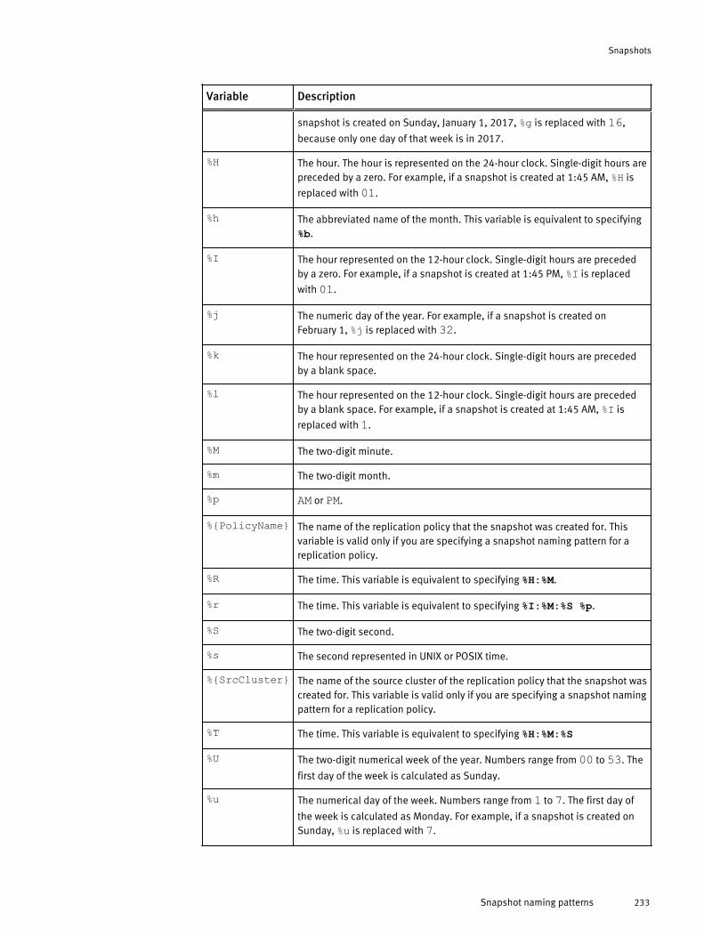
Variable Description
snapshot is created on Sunday, January 1, 2017, %g is replaced with 16,
because only one day of that week is in 2017.
%H The hour. The hour is represented on the 24-hour clock. Single-digit hours arepreceded by a zero. For example, if a snapshot is created at 1:45 AM, %H is
replaced with 01.
%h The abbreviated name of the month. This variable is equivalent to specifying%b.
%I The hour represented on the 12-hour clock. Single-digit hours are precededby a zero. For example, if a snapshot is created at 1:45 PM, %I is replaced
with 01.
%j The numeric day of the year. For example, if a snapshot is created onFebruary 1, %j is replaced with 32.
%k The hour represented on the 24-hour clock. Single-digit hours are precededby a blank space.
%l The hour represented on the 12-hour clock. Single-digit hours are precededby a blank space. For example, if a snapshot is created at 1:45 AM, %I is
replaced with 1.
%M The two-digit minute.
%m The two-digit month.
%p AM or PM.
%{PolicyName} The name of the replication policy that the snapshot was created for. Thisvariable is valid only if you are specifying a snapshot naming pattern for areplication policy.
%R The time. This variable is equivalent to specifying %H:%M.
%r The time. This variable is equivalent to specifying %I:%M:%S %p.
%S The two-digit second.
%s The second represented in UNIX or POSIX time.
%{SrcCluster} The name of the source cluster of the replication policy that the snapshot wascreated for. This variable is valid only if you are specifying a snapshot namingpattern for a replication policy.
%T The time. This variable is equivalent to specifying %H:%M:%S
%U The two-digit numerical week of the year. Numbers range from 00 to 53. The
first day of the week is calculated as Sunday.
%u The numerical day of the week. Numbers range from 1 to 7. The first day of
the week is calculated as Monday. For example, if a snapshot is created onSunday, %u is replaced with 7.
Snapshots
Snapshot naming patterns 233
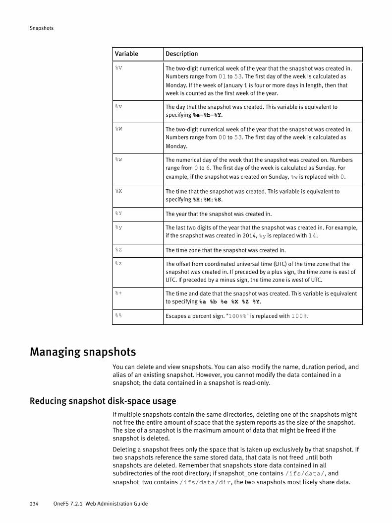
Variable Description
%V The two-digit numerical week of the year that the snapshot was created in.Numbers range from 01 to 53. The first day of the week is calculated as
Monday. If the week of January 1 is four or more days in length, then thatweek is counted as the first week of the year.
%v The day that the snapshot was created. This variable is equivalent tospecifying %e-%b-%Y.
%W The two-digit numerical week of the year that the snapshot was created in.Numbers range from 00 to 53. The first day of the week is calculated as
Monday.
%w The numerical day of the week that the snapshot was created on. Numbersrange from 0 to 6. The first day of the week is calculated as Sunday. For
example, if the snapshot was created on Sunday, %w is replaced with 0.
%X The time that the snapshot was created. This variable is equivalent tospecifying %H:%M:%S.
%Y The year that the snapshot was created in.
%y The last two digits of the year that the snapshot was created in. For example,if the snapshot was created in 2014, %y is replaced with 14.
%Z The time zone that the snapshot was created in.
%z The offset from coordinated universal time (UTC) of the time zone that thesnapshot was created in. If preceded by a plus sign, the time zone is east ofUTC. If preceded by a minus sign, the time zone is west of UTC.
%+ The time and date that the snapshot was created. This variable is equivalentto specifying %a %b %e %X %Z %Y.
%% Escapes a percent sign. "100%%" is replaced with 100%.
Managing snapshotsYou can delete and view snapshots. You can also modify the name, duration period, andalias of an existing snapshot. However, you cannot modify the data contained in asnapshot; the data contained in a snapshot is read-only.
Reducing snapshot disk-space usageIf multiple snapshots contain the same directories, deleting one of the snapshots mightnot free the entire amount of space that the system reports as the size of the snapshot.The size of a snapshot is the maximum amount of data that might be freed if thesnapshot is deleted.
Deleting a snapshot frees only the space that is taken up exclusively by that snapshot. Iftwo snapshots reference the same stored data, that data is not freed until bothsnapshots are deleted. Remember that snapshots store data contained in allsubdirectories of the root directory; if snapshot_one contains /ifs/data/, andsnapshot_two contains /ifs/data/dir, the two snapshots most likely share data.
Snapshots
234 OneFS 7.2.1 Web Administration Guide
If you delete a directory, and then re-create it, a snapshot containing the directory storesthe entire re-created directory, even if the files in that directory are never modified.
Deleting multiple snapshots that contain the same directories is more likely to free datathan deleting multiple snapshots that contain different directories.
If multiple snapshots contain the same directories, deleting older snapshots is morelikely to free disk-space than deleting newer snapshots.
Snapshots that are assigned expiration dates are automatically marked for deletion bythe snapshot daemon. If the daemon is disabled, snapshots will not be automaticallydeleted by the system. It is recommended that you do not disable the snapshot daemon.
Delete snapshotsYou can delete a snapshot if you no longer want to access the data contained in thesnapshot.
OneFS frees disk space occupied by deleted snapshots when the SnapshotDelete job isrun. Also, if you delete a snapshot that contains clones or cloned files, data in a shadowstore might no longer be referenced by files on the cluster; OneFS deletes unreferenceddata in a shadow store when the ShadowStoreDelete job is run. OneFS routinely runsboth the shadow store delete and SnapshotDelete jobs. However, you can also manuallyrun the jobs at any time.
Procedure
1. Click Data Protection > SnapshotIQ > Snapshots.
2. Specify the snapshots that you want to delete.
a. For each snapshot you want to delete, in the Saved File System Snapshots table,in the row of a snapshot, select the check box.
b. From the Select an action list, select Delete.
c. In the confirmation dialog box, click Delete.
3. (Optional) To increase the speed at which deleted snapshot data is freed on thecluster, run the SnapshotDelete job.
a. Click Cluster Management > Job Operations > Job Types.
b. In the Job Types area, in the SnapshotDelete row, from the Actions column, selectStart Job.
c. Click Start.
4. (Optional) To increase the speed at which deleted data shared between deduplicatedand cloned files is freed on the cluster, run the ShadowStoreDelete job.
Run the ShadowStoreDelete job only after you run the SnapshotDelete job.
a. Click Cluster Management > Job Operations > Job Types.
b. In the Job Types area, in the ShadowStoreDelete row, from the Actions column,select Start Job.
c. Click Start.
Snapshots
Delete snapshots 235
Modify snapshot attributesYou can modify the name and expiration date of a snapshot.
Procedure
1. Click File System Management > SnapshotIQ > Snapshots.
2. In the Saved File System Snapshots table, in the row of a snapshot, click ViewDetails.
3. In the Snapshot Details area, modify snapshot attributes.
4. Next to each snapshot attribute that you modified, click Save.
Assign a snapshot alias to a snapshotYou can assign a snapshot alias to a snapshot.
Procedure
1. Click Data Protection > SnapshotIQ > Snapshots.
2. Above the Saved File System Snapshots table, click View snapshot aliases.
3. In the Snapshot Aliases table, in the row of an alias, click View details.
4. In the Snapshot Alias Details pane, in the Alias Name area, click Edit.
5. In the Alias Name field, type a new alias name.
6. Click Save.
View snapshotsYou can view snapshots.
Procedure
1. Click Data Protection > SnapshotIQ > Snapshots.
The 50 most recently generated snapshots appear in the Saved File SystemSnapshots table.
2. (Optional) To view additional snapshots, at the bottom of the Saved File SystemSnapshots table, click Show 50 more.
Snapshot informationYou can view information about snapshots, including the total amount of spaceconsumed by all snapshots.
The following information is displayed in the Saved Snapshots area:
SnapshotIQ Status
Indicates whether a SnapshotIQ license has been activated on the cluster.
Total Number of Saved Snapshots
Indicates the total number of snapshots that exist on the cluster.
Total Number of Snapshots Pending Deletion
Indicates the total number of snapshots that were deleted on the cluster since thelast snapshot delete job was run. The space consumed by the deleted snapshots isnot freed until the snapshot delete job is run again.
Snapshots
236 OneFS 7.2.1 Web Administration Guide
Total Number of Snapshot Aliases
Indicates the total number of snapshot aliases that exist on the cluster.
Capacity Used by Saved Snapshots
Indicates the total amount of space consumed by all snapshots.
Restoring snapshot dataYou can restore snapshot data through various methods. You can revert a snapshot oraccess snapshot data through the snapshots directory.
From the snapshots directory, you can either clone a file or copy a directory or a file. Thesnapshots directory can be accessed through Windows Explorer or a UNIX command line.You can disable and enable access to the snapshots directory for any of these methodsthrough snapshots settings.
Revert a snapshotYou can revert a directory back to the state it was in when a snapshot was taken. BeforeOneFS reverts a snapshot, OneFS generates a snapshot of the directory being reverted, sothat data stored in the directory is not lost. OneFS does not delete a snapshot afterreverting it.
Before you begin
l Create a SnapRevert domain for the directory.
l Create a snapshot of a directory.
Procedure
1. Click Cluster Management > Job Operations > Job Types.
2. In the Job Types area, in the SnapRevert row, from the Actions column, select StartJob.
3. (Optional) To specify a priority for the job, from the Priority list, select a priority.
Lower values indicate a higher priority. If you do not specify a priority, the job isassigned the default snapshot revert priority.
4. (Optional) To specify the amount of cluster resources the job is allowed to consume,from the Impact policy list, select an impact policy.
If you do not specify a policy, the job is assigned the default snapshot revert policy.
5. In the Snapshot ID to revert field, type the name or ID of the snapshot that you want torevert, and then click Start.
Restore a file or directory using Windows ExplorerIf the Microsoft Shadow Copy Client is installed on your computer, you can use it torestore files and directories that are stored in snapshots.
This method of restoring files and directories does not preserve the original permissions.Instead, this method assigns the file or directory the same permissions as the directoryyou are copying that file or directory into. To preserve permissions while restoring datafrom a snapshot, run the cp command with the -a option on a UNIX command line.
Snapshots
Restoring snapshot data 237
Note
You can access up to 64 snapshots of a directory through Windows explorer, starting withthe most recent snapshot. To access more than 64 snapshots for a directory, access thecluster through a UNIX command line.
Procedure
1. In Windows Explorer, navigate to the directory that you want to restore or the directorythat contains the file that you want to restore.
If the directory has been deleted, you must recreate the directory.
2. Right-click the folder, and then click Properties.
3. In the Properties window, click the Previous Versions tab.
4. Select the version of the folder that you want to restore or the version of the folderthat contains the version of the file that you want to restore.
5. Restore the version of the file or directory.
l To restore all files in the selected directory, click Restore.
l To copy the selected directory to another location, click Copy and then specify alocation to copy the directory to.
l To restore a specific file, click Open, and then copy the file into the originaldirectory, replacing the existing copy with the snapshot version.
Restore a file or directory through a UNIX command lineYou can restore a file or directory through a UNIX command line.
Procedure
1. Open a connection to the cluster through a UNIX command line.
2. (Optional) To view the contents of the snapshot you want to restore a file or directoryfrom, run the ls command for a directory contained in the snapshots root directory.
For example, the following command displays the contents of the /archivedirectory contained in Snapshot2012Jun04:
ls /ifs/.snapshot/Snapshot2014Jun04/archive3. Copy the file or directory by using the cp command.
For example, the following command creates a copy of file1:
cp -a /ifs/.snapshot/Snapshot2014Jun04/archive/file1 \/ifs/archive/file1_copy
Clone a file from a snapshotYou can clone a file from a snapshot. This procedure is available only through thecommand-line interface (CLI).
Procedure
1. Open a secure shell (SSH) connection to any node in the cluster and log in.
2. To view the contents of the snapshot you want to restore a file or directory from, runthe ls command for a subdirectory of the snapshots root directory.
Snapshots
238 OneFS 7.2.1 Web Administration Guide
For example, the following command displays the contents of the /archivedirectory contained in Snapshot2014Jun04:
ls /ifs/.snapshot/Snapshot2014Jun04/archive3. Clone a file from the snapshot by running the cp command with the -c option.
For example, the following command clones test.txt from Snapshot2014Jun04:
cp -c /ifs/.snapshot/Snapshot2014Jun04/archive/test.txt \/ifs/archive/test_clone.text
Managing snapshot schedulesYou can modify, delete, and view snapshot schedules.
Modify a snapshot scheduleYou can modify a snapshot schedule. Any changes to a snapshot schedule are appliedonly to snapshots generated after the modifications are made. Existing snapshots are notaffected by schedule modifications.
If you modify the alias of a snapshot schedule, the alias is assigned to the next snapshotgenerated based on the schedule. However, if you do this, the old alias is not removedfrom the last snapshot that it was assigned to. Unless you manually remove the old alias,the alias will remain attached to the last snapshot that it was assigned to.
Procedure
1. Click Data Protection > SnapshotIQ > Snapshot Schedules.
2. In the Snapshot Schedules table, in the row of the snapshot schedule you want tomodify, click View details.
3. In the Snapshot Schedule Details area, modify snapshot schedule attributes.
4. Next to each snapshot schedule attribute that you modified, click Save.
Delete a snapshot scheduleYou can delete a snapshot schedule. Deleting a snapshot schedule will not deletesnapshots that were previously generated according to the schedule.
Procedure
1. Click Data Protection > SnapshotIQ > Snapshot Schedules.
2. In the Snapshot Schedules table, in the row of the snapshot schedule you want todelete, click Delete.
3. In the Confirm Delete dialog box, click Delete.
View snapshot schedulesYou can view snapshot schedules.
Procedure
1. Click Data Protection > SnapshotIQ > Snapshot Schedules.
2. In the Snapshot Schedules table, view snapshot schedules.
3. (Optional) To view detailed information about a snapshot schedule, in the SnapshotSchedules table, in the row of the snapshot schedule that you want to view, click Viewdetails.
Snapshots
Managing snapshot schedules 239
Snapshot schedule settings are displayed in the Snapshot Schedule Details area.Snapshots that are scheduled to be generated according to the schedule aredisplayed in the Snapshot Calendar area.
Managing snapshot aliasesYou can configure snapshot schedules to assign a snapshot alias to the most recentsnapshot created by a snapshot schedule. You can also manually assign snapshotaliases to specific snapshots or the live version of the file system.
Configure a snapshot alias for a snapshot scheduleYou can configure a snapshot schedule to assign a snapshot alias to the most recentsnapshot created by the schedule.
Procedure
1. Click Data Protection > SnapshotIQ > Snapshot Schedules
2. In the Snapshot Schedules table, in the row of the snapshot schedule you want toconfigure, click View details.
3. Next to Snapshot Alias, click Create an Alias.
4. In the Snapshot Alias area, select Yes.
5. In the Alias Name field, type the name of the snapshot alias.
6. In the Snapshot Alias area, click Save.
Assign a snapshot alias to a snapshotYou can assign a snapshot alias to a snapshot.
Procedure
1. Click Data Protection > SnapshotIQ > Snapshots.
2. Above the Saved File System Snapshots table, click View snapshot aliases.
3. In the Snapshot Aliases table, in the row of an alias, click View details.
4. In the Snapshot Alias Details pane, in the Alias Name area, click Edit.
5. In the Alias Name field, type a new alias name.
6. Click Save.
Reassign a snapshot alias to the live file systemYou can reassign a snapshot alias to redirect clients from a snapshot to the live filesystem. This procedure is available only through the command-line interface (CLI).
Procedure
1. Run the isi snapshot aliases modify command.
The following command reassigns the latestWeekly alias to the live file system:
isi snapshot aliases modify latestWeekly --target LIVE
Snapshots
240 OneFS 7.2.1 Web Administration Guide
View snapshot aliasesYou can view a list of all snapshot aliases. This procedure is available only through thecommand-line interface (CLI).
Procedure
1. View a list of all snapshot aliases by running the following command:
isi snapshot aliases list
If a snapshot alias references the live version of the file system, the Target ID is-1.
2. (Optional) View information about a specific snapshot by running the isisnapshot aliases view command.
The following command displays information about latestWeekly:
isi snapshot aliases view latestWeekly
Snapshot alias informationYou can view information about snapshot aliases through the output of the isisnapshot aliases view command.
ID
The numerical ID of the snapshot alias.
Name
The name of the snapshot alias.
Target ID
The numerical ID of the snapshot that is referenced by the alias.
Target Name
The name of the snapshot that is referenced by the alias.
Created
The date that the snapshot alias was created.
Managing with snapshot locksYou can delete, create, and modify the expiration date of snapshot locks.
CAUTION
It is recommended that you do not create, delete, or modify snapshots locks unless youare instructed to do so by Isilon Technical Support.
Deleting a snapshot lock that was created by OneFS might result in data loss. If youdelete a snapshot lock that was created by OneFS, it is possible that the correspondingsnapshot might be deleted while it is still in use by OneFS. If OneFS cannot access asnapshot that is necessary for an operation, the operation will malfunction and data lossmight result. Modifying the expiration date of a snapshot lock created by OneFS can alsoresult in data loss because the corresponding snapshot can be deleted prematurely.
Snapshots
View snapshot aliases 241
Create a snapshot lockYou can create snapshot locks that prevent snapshots from being deleted. Thisprocedure is available only through the command-line interface (CLI).
Although you can prevent a snapshot from being automatically deleted by creating asnapshot lock, it is recommended that you do not create snapshot locks. To prevent asnapshot from being automatically deleted, it is recommended that you extend theduration period of the snapshot.
Procedure
1. Open a secure shell (SSH) connection to any node in the cluster and log in.
2. Create a snapshot lock by running the isi snapshot locks create command.
For example, the following command applies a snapshot lock to"SnapshotApril2012", sets the lock to expire in one month, and adds a description of"Maintenance Lock":
isi snapshot locks create SnapshotApril2012 --expires 1M \--comment "Maintenance Lock"
Modify a snapshot lock expiration dateYou can modify the expiration date of a snapshot lock. This procedure is available onlythrough the command-line interface (CLI).
CAUTION
It is recommended that you do not modify the expiration dates of snapshot locks.
Procedure
1. Open a secure shell (SSH) connection to any node in the cluster and log in.
2. Run the isi snapshot locks modify command.
The following command sets an expiration date two days from the present date for asnapshot lock with an ID of 1 that is applied to a snapshot namedSnapshotApril2014:
isi snapshot locks modify SnapshotApril2014 1 --expires 2D
Delete a snapshot lockYou can delete a snapshot lock. This procedure is available only through the command-line interface (CLI).
CAUTION
It is recommended that you do not delete snapshot locks.
Procedure
1. Open a secure shell (SSH) connection to any node in the cluster and log in.
2. Delete a snapshot lock by running the isi snapshot locks delete command.
Snapshots
242 OneFS 7.2.1 Web Administration Guide

For example, the following command deletes a snapshot lock that is applied toSnapshotApril2014 and has a lock ID of 1:
isi snapshot locks delete Snapshot2014Apr16 1
The system prompts you to confirm that you want to delete the snapshot lock.
3. Type yes and then press ENTER.
Snapshot lock informationYou can view snapshot lock information through the isi snapshot locks view andisi snapshot locks list commands.
ID
Numerical identification number of the snapshot lock.
Comment
Description of the snapshot lock. This can be any string specified by a user.
Expires
The date that the snapshot lock will be automatically deleted by OneFS.
Count
The number of times the snapshot lock is held.The file clone operation can hold a single snapshot lock multiple times. If multiplefile clones are created simultaneously, the file clone operation holds the same lockmultiple times, rather than creating multiple locks. If you delete a snapshot lock thatis held more than once, you will delete only one of the instances that the lock isheld. In order to delete a snapshot lock that is held multiple times, you must deletethe snapshot lock the same number of times as displayed in the count field.
Configure SnapshotIQ settingsYou can configure SnapshotIQ settings that determine how snapshots can be created andthe methods that users can access snapshot data.
Procedure
1. Click Data Protection > SnapshotIQ > Settings.
2. Modify SnapshotIQ settings, and then click Save.
SnapshotIQ settingsSnapshotIQ settings determine how snapshots behave and can be accessed.
The following SnapshotIQ settings can be configured:
Snapshot Scheduling
Determines whether snapshots can be generated.
Note
Disabling snapshot generation might cause some OneFS operations to fail. It isrecommended that you do not disable this setting.
Snapshots
Snapshot lock information 243

Auto-create Snapshots
Determines whether snapshots are automatically generated according tosnapshot schedules.
Auto-delete Snapshots
Determines whether snapshots are automatically deleted according to theirexpiration dates.
NFS Visibility & Accessibility
Root Directory Accessible
Determines whether snapshot directories are accessible through NFS.
Root Directory Visible
Determines whether snapshot directories are visible through NFS.
Sub-directories Accessible
Determines whether snapshot subdirectories are accessible through NFS.
SMB Visibility & Accessible
Root Directory Accessible
Determines whether snapshot directories are accessible through SMB.
Root Directory Visible
Determines whether snapshot directories are visible through SMB.
Sub-directories Accessible
Determines whether snapshot subdirectories are accessible through SMB.
Local Visibility & Accessibility
Root Directory Accessible
Determines whether snapshot directories are accessible through the local filesystem. You can access the local file system through an SSH connection or thelocal console.
Root Directory Visible
Determines whether snapshot directories are visible through the local filesystem. You can access the local file system through an SSH connection or thelocal console.
Sub-directories Accessible
Determines whether snapshot subdirectories are accessible through the localfile system. You can access the local file system through an SSH connection orthe local console.
Snapshots
244 OneFS 7.2.1 Web Administration Guide
Set the snapshot reserveYou can specify a minimum percentage of cluster-storage capacity that you want toreserve for snapshots. This procedure is available only through the command-lineinterface (CLI).
The snapshot reserve does not limit the amount of space that snapshots are allowed toconsume on the cluster. Snapshots can consume more than the percentage of capacityspecified by the snapshot reserve. It is recommended that you do not specify a snapshotreserve.
Procedure
1. Open a secure shell (SSH) connection to any node in the cluster and log in.
2. Set the snapshot reserve by running the isi snapshot settings modifycommand with the --reserve option.
For example, the following command sets the snapshot reserve to 20%:
isi snapshot settings modify --reserve 20
Snapshots
Set the snapshot reserve 245

Snapshots
246 OneFS 7.2.1 Web Administration Guide

CHAPTER 13
Deduplication with SmartDedupe
This section contains the following topics:
l Deduplication overview.......................................................................................248l Deduplication jobs..............................................................................................248l Data replication and backup with deduplication..................................................249l Snapshots with deduplication.............................................................................249l Deduplication considerations..............................................................................249l Shadow-store considerations..............................................................................250l SmartDedupe license functionality......................................................................250l Managing deduplication..................................................................................... 250
Deduplication with SmartDedupe 247

Deduplication overviewThe SmartDedupe software module enables you to save storage space on your cluster byreducing redundant data. Deduplication maximizes the efficiency of your cluster bydecreasing the amount of storage required to store multiple files with similar blocks.
SmartDedupe deduplicates data by scanning an Isilon cluster for identical data blocks.Each block is 8 KB. If SmartDedupe finds duplicate blocks, SmartDedupe moves a singlecopy of the blocks to a hidden file called a shadow store. SmartDedupe then deletes theduplicate blocks from the original files and replaces the blocks with pointers to theshadow store.
Deduplication is applied at the directory level, targeting all files and directoriesunderneath one or more root directories. You can first assess a directory fordeduplication and determine the estimated amount of space you can expect to save. Youcan then decide whether to deduplicate the directory. After you begin deduplicating adirectory, you can monitor how much space is saved by deduplication in real time.
SmartDedupe does not deduplicate files that are 32 KB and smaller, because doing sowould consume more cluster resources than the storage savings are worth. Each shadowstore can contain up to 255 blocks. Each block in a shadow store can be referenced32000 times.
Deduplication jobsDeduplication is performed by maintenance jobs referred to as deduplication jobs. Youcan monitor and control deduplication jobs as you would any other maintenance job onthe cluster. Although the overall performance impact of deduplication is minimal, thededuplication job consumes 256 MB of memory per node.
When a deduplication job is first run on a cluster, SmartDedupe samples blocks fromeach file and creates index entries for those blocks. If the index entries of two blocksmatch, SmartDedupe scans the blocks adjacent to the matching pair and thendeduplicates all duplicate blocks. After a deduplication job samples a file once, newdeduplication jobs will not sample the file again until the file is modified.
The first deduplication job you run might take significantly longer to complete thansubsequent deduplication jobs. The first deduplication job must scan all files under thespecified directories to generate the initial index. If subsequent deduplication jobs take along time to complete, this most likely indicates that a large amount of data is beingdeduplicated. However, it can also indicate that clients are creating a large amount ofnew data on the cluster. If a deduplication job is interrupted during the deduplicationprocess, the job will automatically restart the scanning process from where the job wasinterrupted.
It is recommended that you run deduplication jobs when clients are not modifying dataon the cluster. If clients are continually modifying files on the cluster, the amount ofspace saved by deduplication is minimal because the deduplicated blocks are constantlyremoved from the shadow store. For most clusters, it is recommended that you start adeduplication job every ten days.
The permissions required to modify deduplication settings are not the same as thoseneeded to run a deduplication job. Although a user must have the maintenance jobpermission to run a deduplication job, the user must have the deduplication permissionto modify deduplication settings. By default, the deduplication job is configured to run ata low priority.
Deduplication with SmartDedupe
248 OneFS 7.2.1 Web Administration Guide
Data replication and backup with deduplicationWhen deduplicated files are replicated to another Isilon cluster or backed up to a tapedevice, the deduplicated files no longer share blocks on the target Isilon cluster orbackup device. However, although you can deduplicate data on a target Isilon cluster,you cannot deduplicate data on an NDMP backup device.
Shadows stores are not transferred to target clusters or backup devices. Because of this,deduplicated files do not consume less space than non-deduplicated files when they arereplicated or backed up. To avoid running out of space, you must ensure that targetclusters and tape devices have enough free space to store deduplicated data as if thedata had not been deduplicated. To reduce the amount of storage space consumed on atarget Isilon cluster, you can configure deduplication for the target directories of yourreplication policies. Although this will deduplicate data on the target directory, it will notallow SyncIQ to transfer shadow stores. Deduplication is still performed by deduplicationjobs running on the target cluster.
The amount of cluster resources required to backup and replicate deduplicated data isthe same as for non-deduplicated data. You can deduplicate data while the data is beingreplicated or backed up.
Snapshots with deduplicationYou cannot deduplicate the data stored in a snapshot. However, you can createsnapshots of deduplicated data.
If you create a snapshot for a deduplicated directory, and then modify the contents ofthat directory, the references to shadow stores will be transferred to the snapshot overtime. Therefore, if you enable deduplication before you create snapshots, you will savemore space on your cluster. If you implement deduplication on a cluster that already hasa significant amount of data stored in snapshots, it will take time before the snapshotdata is affected by deduplication. Newly created snapshots can contain deduplicateddata, but snapshots created before deduplication was implemented cannot.
If you plan on reverting a snapshot, it is best to revert the snapshot before running adeduplication job. Restoring a snapshot can overwrite many of the files on the cluster.Any deduplicated files are reverted back to normal files if they are overwritten by asnapshot revert. However, after the snapshot revert is complete, you can deduplicate thedirectory and the space savings persist on the cluster.
Deduplication considerationsDeduplication can significantly increase the efficiency at which you store data. However,the effect of deduplication varies depending on the cluster.
You can reduce redundancy on a cluster by running SmartDedupe. Deduplication createslinks that can impact the speed at which you can read from and write to files. Inparticular, sequentially reading chunks smaller than 512 KB of a deduplicated file can besignificantly slower than reading the same small, sequential chunks of a non-deduplicated file. This performance degradation applies only if you are reading non-cached data. For cached data, the performance for deduplicated files is potentially betterthan non-deduplicated files. If you stream chunks larger than 512 KB, deduplication doesnot significantly impact the read performance of the file. If you intend on streaming 8 KBor less of each file at a time, and you do not plan on concurrently streaming the files, it isrecommended that you do not deduplicate the files.
Deduplication with SmartDedupe
Data replication and backup with deduplication 249
Deduplication is most effective when applied to static or archived files and directories.The less files are modified, the less negative effect deduplication has on the cluster. Forexample, virtual machines often contain several copies of identical files that are rarelymodified. Deduplicating a large number of virtual machines can greatly reduce consumedstorage space.
Shadow-store considerationsShadow stores are hidden files that are referenced by cloned and deduplicated files. Filesthat reference shadow stores behave differently than other files.
l Reading shadow-store references might be slower than reading data directly.Specifically, reading non-cached shadow-store references is slower than reading non-cached data. Reading cached shadow-store references takes no more time thanreading cached data.
l When files that reference shadow stores are replicated to another Isilon cluster orbacked up to a Network Data Management Protocol (NDMP) backup device, theshadow stores are not transferred to the target Isilon cluster or backup device. Thefiles are transferred as if they contained the data that they reference from shadowstores. On the target Isilon cluster or backup device, the files consume the sameamount of space as if they had not referenced shadow stores.
l When OneFS creates a shadow store, OneFS assigns the shadow store to a storagepool of a file that references the shadow store. If you delete the storage pool that ashadow store resides on, the shadow store is moved to a pool occupied by anotherfile that references the shadow store.
l OneFS does not delete a shadow-store block immediately after the last reference tothe block is deleted. Instead, OneFS waits until the ShadowStoreDelete job is run todelete the unreferenced block. If a large number of unreferenced blocks exist on thecluster, OneFS might report a negative deduplication savings until theShadowStoreDelete job is run.
l Shadow stores are protected at least as much as the most protected file thatreferences it. For example, if one file that references a shadow store resides in astorage pool with +2 protection and another file that references the shadow storeresides in a storage pool with +3 protection, the shadow store is protected at +3.
l Quotas account for files that reference shadow stores as if the files contained thedata referenced from shadow stores; from the perspective of a quota, shadow-storereferences do not exist. However, if a quota includes data protection overhead, thequota does not account for the data protection overhead of shadow stores.
SmartDedupe license functionalityYou can deduplicate data only if you activate a SmartDedupe license on a cluster.However, you can assess deduplication savings without activating a SmartDedupelicense.
If you activate a SmartDedupe license, and then deduplicate data, the space savings arenot lost if the license becomes inactive. You can also still view deduplication savingswhile the license is inactive. However, you will not be able to deduplicate additional datauntil you re-activate the SmartDedupe license.
Managing deduplicationYou can manage deduplication on a cluster by first assessing how much space you cansave by deduplicating individual directories. After you determine which directories are
Deduplication with SmartDedupe
250 OneFS 7.2.1 Web Administration Guide
worth deduplicating, you can configure SmartDedupe to deduplicate those directoriesspecifically. You can then monitor the actual amount of disk space you are saving.
Assess deduplication space savingsYou can assess the amount of disk space you will save by deduplicating a directory.
Procedure
1. Click File System Management > Deduplication > Settings.
2. In the Assess Deduplication area, click Browse and select a directory that you want todeduplicate.
If you assess multiple directories, disk savings are not differentiated by directory inthe deduplication report.
3. Click Cluster Management > Job Operations > Job Types.
4. In the Job Types table, in the row of the DedupeAssessment job, from the Actionscolumn, select Start Job.
5. Click Cluster Management > Job Operations > Job Summary.
6. Wait for the assessment job to complete.
When the DedupeAssessment job is complete, the job is removed from the ActiveJobs table.
7. Click File System Management > Deduplication > Summary.
In the Deduplication Assessment Reports table, in the row of the most recentassessment job, click View Details.
8. View the amount of disk space that will be saved if you deduplicate the directory.
The number of blocks that will be deduplicated is displayed in the Deduped blocksfield.
Specify deduplication settingsYou can specify which directories you want to deduplicate.
Procedure
1. Click File System Management > Deduplication > Settings.
2. In the Deduplication Settings area, click Browse and select a directory that you wantto deduplicate.
3. (Optional) Specify additional directories.
a. Click Add another directory path.
b. Click Browse and select a directory that you want to deduplicate.
4. Click Cluster Management > Job Operations > Jobs Types.
5. In the Jobs table, in the row of the Dedupe job, click View/Edit.
6. Click Edit Job Type.
7. Modify the settings of the deduplication job, and then click Save Changes.
Deduplication with SmartDedupe
Assess deduplication space savings 251
View deduplication space savingsYou can view the amount of disk space that you are currently saving with deduplication.
Procedure
1. Click File System Management > Deduplication > Summary.
2. In the Deduplication Savings area, view the amount of disk space saved.
View a deduplication reportAfter a deduplication job completes, you can view information about the job in adeduplication report.
Procedure
1. Click File System Management > Deduplication > Summary.
2. Select a deduplication report.
l To view a report about a deduplication job, in the Deduplication Reports table,click View Report.
l To view a report about a deduplication assessment job, in the DeduplicationAssessment Reports table, click View Report.
Deduplication job report informationYou can view the following deduplication specific information in deduplication jobreports:
Start time
The time the deduplication job started.
End time
The time the deduplication job ended.
Iteration Count
The number of times that SmartDedupe interrupted the sampling process. IfSmartDedupe is sampling a large amount of data, SmartDedupe might interruptsampling in order to start deduplicating the data. After SmartDedupe finishesdeduplicating the sampled data, SmartDedupe will continue sampling the remainingdata.
Scanned blocks
The total number of blocks located underneath the specified deduplicateddirectories.
Sampled blocks
The number of blocks that SmartDedupe created index entries for.
Deduped blocks
The number of blocks that were deduplicated.
Dedupe percent
The percentage of scanned blocks that were deduplicated.
Created dedupe requests
The total number of deduplication requests created. A deduplication request iscreated for each matching pair of data blocks. For example, if you have 3 data blocks
Deduplication with SmartDedupe
252 OneFS 7.2.1 Web Administration Guide
that all match, SmartDedupe creates 2 requests. One of the requests could pair file1and file2 together and the other request could pair file2 and file3 together.
Successful dedupe requests
The number of deduplication requests that completed successfully.
Failed dedupe requests
The number of deduplication requests that failed. If a deduplication request fails, itdoesn't mean that the job failed too. A deduplication request can fail for any numberof reasons. For example, the file might have been modified since it was sampled.
Skipped files
The number of files that were not scanned by the deduplication job. SmartDedupeskips files for a number of reasons. For example, SmartDedupe skips files that havealready been scanned and haven't been modified since. SmartDedupe also skips allfiles that are smaller than 4 KB.
Index entries
The number of entries that currently exist in the index.
Index lookup attempts
The total number of lookups that have been done by earlier deduplication jobs plusthe number of lookups done by this deduplication job. A lookup is when thededuplication job attempts to match a block that was indexed with a block thathasn't been indexed.
Index lookup hits
The number of blocks that matched index entries.
Deduplication informationYou can view the amount of disk space saved by deduplication in the DeduplicationSavings area:
Space Savings
The total amount of physical disk space saved by deduplication, includingprotection overhead and metadata. For example, if you have three identical files thatare all 5 GB, the estimated physical saving would be greater than 10 GB, becausededuplication saved space that would have been occupied by file metadata andprotection overhead.
Deduplicated data
The amount of space on the cluster occupied by directories that were deduplicated.
Other data
The amount of space on the cluster occupied by directories that were notdeduplicated.
Deduplication with SmartDedupe
Deduplication information 253

Deduplication with SmartDedupe
254 OneFS 7.2.1 Web Administration Guide

CHAPTER 14
Data replication with SyncIQ
This section contains the following topics:
l SyncIQ backup and recovery overview.................................................................256l Replication policies and jobs.............................................................................. 256l Replication snapshots.........................................................................................259l Data failover and failback with SyncIQ.................................................................260l Recovery times and objectives for SyncIQ............................................................262l SyncIQ license functionality................................................................................ 262l Creating replication policies................................................................................263l Managing replication to remote clusters..............................................................272l Initiating data failover and failback with SyncIQ.................................................. 274l Performing disaster recovery for SmartLock directories........................................276l Managing replication policies............................................................................. 278l Managing replication to the local cluster............................................................. 283l Managing replication performance rules............................................................. 285l Managing replication reports...............................................................................287l Managing failed replication jobs......................................................................... 288l Managing changelists......................................................................................... 290
Data replication with SyncIQ 255
SyncIQ backup and recovery overviewOneFS enables you to replicate data from one Isilon cluster to another through the SyncIQsoftware module. You must activate a SyncIQ license on both Isilon clusters before youcan replicate data between them.
You can replicate data at the directory level while optionally excluding specific files andsub-directories from being replicated. SyncIQ creates and references snapshots toreplicate a consistent point-in-time image of a root directory. Metadata such as accesscontrol lists (ACLs) and alternate data streams (ADS) are replicated along with data.
SyncIQ enables you to maintain a consistent backup copy of your data on another Isiloncluster. SyncIQ offers automated failover and failback capabilities that enable you tocontinue operations on another Isilon cluster if a primary cluster becomes unavailable.
Replication policies and jobsData replication is coordinated according to replication policies and jobs. Replicationpolicies specify what data is replicated, where the data is replicated to, and how oftenthe data is replicated. Replication jobs are the operations that replicate data from oneIsilon cluster to another. SyncIQ generates replication jobs according to replicationpolicies.
A replication policy specifies two clusters: the source and the target. The cluster on whichthe replication policy exists is the source cluster. The cluster that data is being replicatedto is the target cluster. When a replication policy starts, SyncIQ generates a replicationjob for the policy. When a replication job runs, files from a directory on the source clusterare replicated to a directory on the target cluster; these directories are known as sourceand target directories.
After the first replication job created by a replication policy finishes, the target directoryand all files contained in the target directory are set to a read-only state, and can bemodified only by other replication jobs belonging to the same replication policy. OneFSdoes not limit the number of replication policies that you can create. However, werecommend that you do not create more than 100 policies on a cluster.
Note
To prevent permissions errors, make sure that ACL policy settings are the same acrosssource and target clusters.
You can create two types of replication policies: synchronization policies and copypolicies. A synchronization policy maintains an exact replica of the source directory onthe target cluster. If a file or sub-directory is deleted from the source directory, the file ordirectory is deleted from the target cluster when the policy is run again.
You can use synchronization policies to fail over and fail back data between source andtarget clusters. When a source cluster becomes unavailable, you can fail over data on atarget cluster and make the data available to clients. When the source cluster becomesavailable again, you can fail back the data to the source cluster.
A copy policy maintains recent versions of the files that are stored on the source cluster.However, files that are deleted on the source cluster are not deleted from the targetcluster. Failback is not supported for copy policies. Copy policies are most commonlyused for archival purposes.
Copy policies enable you to remove files from the source cluster without losing those fileson the target cluster. Deleting files on the source cluster improves performance on the
Data replication with SyncIQ
256 OneFS 7.2.1 Web Administration Guide

source cluster while maintaining the deleted files on the target cluster. This can be usefulif, for example, your source cluster is being used for production purposes and your targetcluster is being used only for archiving.
After creating a job for a replication policy, SyncIQ must wait until the job completesbefore it can create another job for the policy. Any number of replication jobs can exist ona cluster at a given time; however, only five replication jobs can run on a source cluster atthe same time. If more than five replication jobs exist on a cluster, the first five jobs runwhile the others are queued to run. The number of replication jobs that a single targetcluster can support concurrently is dependent on the number of workers available on thetarget cluster.
You can replicate any number of files and directories with a single replication job. Youcan prevent a large replication job from overwhelming the system by limiting the amountof cluster resources and network bandwidth that data synchronization is allowed toconsume. Because each node in a cluster is able to send and receive data, the speed atwhich data is replicated increases for larger clusters.
Automated replication policiesYou can manually start a replication policy at any time, but you can also configurereplication policies to start automatically based on source directory modifications or aschedule.
You can configure a replication policy to run according to a schedule, so that you cancontrol when replication is performed. You can also configure a replication policy to startwhen SyncIQ detects a modification to the source directory, so that SyncIQ maintains amore current version of your data on the target cluster.
Scheduling a policy can be useful under the following conditions:
l You want to replicate data when user activity is minimal
l You can accurately predict when modifications will be made to the data
Configuring a policy to start when changes are made to the source directory can be usefulunder the following conditions:
l You want retain a consistent copy of your data at all times
l You are expecting a large number of changes at unpredictable intervals
For policies that are configured to start whenever changes are made to the sourcedirectory, SyncIQ checks the source directories every ten seconds. SyncIQ does notaccount for excluded files or directories when detecting changes, so policies that excludefiles or directories from replication might be run unnecessarily. For example, assume thatnewPolicy replicates /ifs/data/media but excludes /ifs/data/media/temp. If amodification is made to /ifs/data/media/temp/file.txt, SyncIQ will runnewPolicy, but will not replicate /ifs/data/media/temp/file.txt.
If a policy is configured to start whenever changes are made to its source directory, and areplication job fails, SyncIQ will wait one minute before attempting to run the policyagain. SyncIQ will increase this delay exponentially for each failure up to a maximumdelay of eight hours. You can override the delay by running the policy manually at anytime. After a job for the policy completes successfully, SyncIQ will resume checking thesource directory every ten seconds.
Source and target cluster associationSyncIQ associates a replication policy with a target cluster by marking the target clusterwhen the job runs for the first time. Even if you modify the name or IP address of the
Data replication with SyncIQ
Automated replication policies 257

target cluster, the mark persists on the target cluster. When a replication policy is run,SyncIQ checks the mark to ensure that data is being replicated to the correct location.
On the target cluster, you can manually break an association between a replication policyand target directory. Breaking the association between a source and target cluster causesthe mark on the target cluster to be deleted. You might want to manually break a targetassociation if an association is obsolete. If you break the association of a policy, thepolicy is disabled on the source cluster and you cannot run the policy. If you want to runthe disabled policy again, you must reset the replication policy.
Breaking a policy association causes either a full replication or differential replication tooccur the next time you run the replication policy. During a full or differential replication,SyncIQ creates a new association between the source and target clusters. Depending onthe amount of data being replicated, a full or differential replication can take a very longtime to complete.
CAUTION
Changes to the configuration of the target cluster outside of SyncIQ can introduce anerror condition that effectively breaks the association between the source and targetcluster. For example, changing the DNS record of the target cluster could cause thisproblem. If you need to make significant configuration changes to the target clusteroutside of SyncIQ, make sure that your SyncIQ policies can still connect to the targetcluster.
Full and differential replicationIf a replication policy encounters an issue that cannot be fixed (for example, if theassociation was broken on the target cluster), you might need to reset the replicationpolicy. If you reset a replication policy, SyncIQ performs either a full or differentialreplication the next time the policy is run. You can specify the type of replication thatSyncIQ performs.
During a full replication, SyncIQ transfers all data from the source cluster regardless ofwhat data exists on the target cluster. A full replication consumes large amounts ofnetwork bandwidth and can take a very long time to complete. However, a full replicationis less strenuous on CPU usage than a differential replication.
During a differential replication, SyncIQ first checks whether a file already exists on thetarget cluster and then transfers only data that does not already exist on the targetcluster. A differential replication consumes less network bandwidth than a fullreplication; however, differential replications consume more CPU. Differential replicationcan be much faster than a full replication if there is an adequate amount of available CPUfor the differential replication job to consume.
Controlling replication job resource consumptionYou can create rules that limit the network traffic created and the rate at which files aresent by replication jobs. You can also specify the number of workers that are spawned bya replication policy to limit the amount of cluster resources that are consumed. Also, youcan restrict a replication policy to connect only to a specific storage pool.
You can create network-traffic rules that control the amount of network traffic generatedby replication jobs during specified time periods. These rules can be useful if, forexample, you want to limit the amount of network traffic created during other resource-intensive operations.
Data replication with SyncIQ
258 OneFS 7.2.1 Web Administration Guide
You can create multiple network traffic rules to enforce different limitations at differenttimes. For example, you might allocate a small amount of network bandwidth during peakbusiness hours, but allow unlimited network bandwidth during non-peak hours.
When a replication job runs, OneFS generates workers on the source and target cluster.Workers on the source cluster send data while workers on the target cluster write data.OneFS generates no more than 40 workers for a replication job. You can modify themaximum number of workers generated per node to control the amount of resources thata replication job is allowed to consume. For example, you can increase the maximumnumber of workers per node to increase the speed at which data is replicated to thetarget cluster.
You can also reduce resource consumption through file-operation rules that limit the rateat which replication policies are allowed to send files. However, it is recommended thatyou only create file-operation rules if the files you intend to replicate are predictablysimilar in size and not especially large.
Replication reportsAfter a replication job completes, SyncIQ generates a report that contains detailedinformation about the job, including how long the job ran, how much data wastransferred, and what errors occurred.
If a replication report is interrupted, SyncIQ might create a subreport about the progressof the job so far. If the job is then restarted, SyncIQ creates another subreport about theprogress of the job until the job either completes or is interrupted again. SyncIQ creates asubreport each time the job is interrupted until the job completes successfully. If multiplesubreports are created for a job, SyncIQ combines the information from the subreportsinto a single report.
SyncIQ routinely deletes replication reports. You can specify the maximum number ofreplication reports that SyncIQ retains and the length of time that SyncIQ retainsreplication reports. If the maximum number of replication reports is exceeded on acluster, SyncIQ deletes the oldest report each time a new report is created.
You cannot customize the content of a replication report.
Note
If you delete a replication policy, SyncIQ automatically deletes any reports that weregenerated for that policy.
Replication snapshotsSyncIQ generates snapshots to facilitate replication, failover, and failback between Isilonclusters. Snapshots generated by SyncIQ can also be used for archival purposes on thetarget cluster.
Source cluster snapshotsSyncIQ generates snapshots on the source cluster to ensure that a consistent point-in-time image is replicated and that unaltered data is not sent to the target cluster.
Before running a replication job, SyncIQ creates a snapshot of the source directory.SyncIQ then replicates data according to the snapshot rather than the current state of thecluster, allowing users to modify source-directory files while ensuring that an exact point-in-time image of the source directory is replicated.
Data replication with SyncIQ
Replication reports 259
For example, if a replication job of /ifs/data/dir/ starts at 1:00 PM and finishes at1:20 PM, and /ifs/data/dir/file is modified at 1:10 PM, the modifications are notreflected on the target cluster, even if /ifs/data/dir/file is not replicated until1:15 PM.
You can replicate data according to a snapshot generated with the SnapshotIQ tool. Ifyou replicate data according to a SnapshotIQ snapshot, SyncIQ does not generateanother snapshot of the source directory. This method can be useful if you want toreplicate identical copies of data to multiple Isilon clusters.
SyncIQ generates source snapshots to ensure that replication jobs do not transferunmodified data. When a job is created for a replication policy, SyncIQ checks whether itis the first job created for the policy. If it is not the first job created for the policy, SyncIQcompares the snapshot generated for the earlier job with the snapshot generated for thenew job.
SyncIQ replicates only data that has changed since the last time a snapshot wasgenerated for the replication policy. When a replication job is completed, SyncIQ deletesthe previous source-cluster snapshot and retains the most recent snapshot until the nextjob is run.
Target cluster snapshotsWhen a replication job is run, SyncIQ generates a snapshot on the target cluster tofacilitate failover operations. When the next replication job is created for the replicationpolicy, the job creates a new snapshot and deletes the old one.
If a SnapshotIQ license has been activated on the target cluster, you can configure areplication policy to generate additional snapshots that remain on the target cluster evenas subsequent replication jobs run.
SyncIQ generates target snapshots to facilitate failover on the target cluster regardless ofwhether a SnapshotIQ license has been configured on the target cluster. Failoversnapshots are generated when a replication job completes. SyncIQ retains only onefailover snapshot per replication policy, and deletes the old snapshot after the newsnapshot is created.
If a SnapshotIQ license has been activated on the target cluster, you can configureSyncIQ to generate archival snapshots on the target cluster that are not automaticallydeleted when subsequent replication jobs run. Archival snapshots contain the same dataas the snapshots that are generated for failover purposes. However, you can configurehow long archival snapshots are retained on the target cluster. You can access archivalsnapshots the same way that you access other snapshots generated on a cluster.
Data failover and failback with SyncIQSyncIQ enables you to perform automated data failover and failback operations betweenIsilon clusters. If a cluster is rendered unusable, you can fail over to another Isiloncluster, enabling clients to access their data on the other cluster. If the unusable clusterbecomes accessible again, you can fail back to the original Isilon cluster.
For the purposes of explaining failover and failback procedures, the cluster originallyaccessed by clients is referred to as the primary cluster, and the cluster that client data isoriginally replicated to is referred to as the secondary cluster. Failover is the process thatallows clients to modify data on a secondary cluster. Failback is the process that allowsclients to access data on the primary cluster again and begins to replicate data back tothe secondary cluster.
Data replication with SyncIQ
260 OneFS 7.2.1 Web Administration Guide
Failover and failback can be useful in disaster recovery procedures. For example, if aprimary cluster is damaged by a natural disaster, you can migrate clients to a secondarycluster until the primary cluster is repaired and then migrate the clients back to theprimary cluster.
You can fail over and fail back to facilitate scheduled cluster maintenance. For example, ifyou are upgrading the primary cluster, you might want to migrate clients to a secondarycluster until the upgrade is complete and then migrate clients back to the primary cluster.
Note
Data failover and failback is not supported for SmartLock directories.
Data failoverData failover is the process of preparing data on a secondary cluster to be modified byclients. After you fail over to a secondary cluster, you can redirect clients to modify theirdata on the secondary cluster.
Before failover is performed, you must create and run a replication policy on the primarycluster. You initiate the failover process on the secondary cluster. Failover is performedper replication policy; to migrate data that is spread across multiple replication policies,you must initiate failover for each replication policy.
You can use any replication policy to fail over. However, if the action of the replicationpolicy is set to copy, any file that was deleted on the primary cluster will be present onthe secondary cluster. When the client connects to the secondary cluster, all files thatwere deleted on the primary cluster will be available to the client.
If you initiate failover for a replication policy while an associated replication job isrunning, the failover operation completes but the replication job fails. Because datamight be in an inconsistent state, SyncIQ uses the snapshot generated by the lastsuccessful replication job to revert data on the secondary cluster to the last recoverypoint.
If a disaster occurs on the primary cluster, any modifications to data that were made afterthe last successful replication job started are not reflected on the secondary cluster.When a client connects to the secondary cluster, their data appears as it was when thelast successful replication job was started.
Data failbackData failback is the process of restoring clusters to the roles they occupied before afailover operation. After data failback is complete, the primary cluster hosts clients andreplicates data to the secondary cluster for backup.
The first step in the failback process is updating the primary cluster with all of themodifications that were made to the data on the secondary cluster. The next step in thefailback process is preparing the primary cluster to be accessed by clients. The final stepin the failback process is resuming data replication from the primary to the secondarycluster. At the end of the failback process, you can redirect users to resume accessingtheir data on the primary cluster.
You can fail back data with any replication policy that meets all of the following criteria:
l The source directory is not a SmartLock directory.
l The policy has been failed over.
l The policy is a synchronization policy.
l The policy does not exclude any files or directories from replication.
Data replication with SyncIQ
Data failover 261
Recovery times and objectives for SyncIQThe Recovery Point Objective (RPO) and the Recovery Time Objective (RTO) aremeasurements of the impacts that a disaster can have on business operations. You cancalculate your RPO and RTO for a disaster recovery with replication policies.
RPO is the maximum amount of time for which data is lost if a cluster suddenly becomesunavailable. For an Isilon cluster, the RPO is the amount of time that has passed sincethe last completed replication job started. The RPO is never greater than the time it takesfor two consecutive replication jobs to run and complete.
If a disaster occurs while a replication job is running, the data on the secondary cluster isreverted to the state it was in when the last replication job completed. For example,consider an environment in which a replication policy is scheduled to run every threehours, and replication jobs take two hours to complete. If a disaster occurs an hour aftera replication job begins, the RPO is four hours, because it has been four hours since acompleted job began replicating data.
RTO is the maximum amount of time required to make backup data available to clientsafter a disaster. The RTO is always less than or approximately equal to the RPO,depending on the rate at which replication jobs are created for a given policy.
If replication jobs run continuously, meaning that another replication job is created forthe policy before the previous replication job completes, the RTO is approximately equalto the RPO. When the secondary cluster is failed over, the data on the cluster is reset tothe state it was in when the last job completed; resetting the data takes an amount oftime proportional to the time it took users to modify the data.
If replication jobs run on an interval, meaning that there is a period of time after areplication job completes before the next replication job for the policy starts, therelationship between RTO and RPO depends on whether a replication job is running whenthe disaster occurs. If a job is in progress when a disaster occurs, the RTO is roughlyequal to the RPO. However, if a job is not running when a disaster occurs, the RTO isnegligible because the secondary cluster was not modified since the last replication jobran, and the failover process is almost instantaneous.
SyncIQ license functionalityYou can replicate data to another Isilon cluster only if you activate a SyncIQ license onboth the local cluster and the target cluster.
If a SyncIQ license becomes inactive, you cannot create, run, or manage replicationpolicies. Also, all previously created replication policies are disabled. Replication policiesthat target the local cluster are also disabled. However, data that was previouslyreplicated to the local cluster is still available.
Data replication with SyncIQ
262 OneFS 7.2.1 Web Administration Guide
Creating replication policiesYou can create replication policies that determine when data is replicated with SyncIQ.
Excluding directories in replicationYou can exclude directories from being replicated by replication policies even if thedirectories exist under the specified source directory.
Note
Failback is not supported for replication policies that exclude directories.
By default, all files and directories under the source directory of a replication policy arereplicated to the target cluster. However, you can prevent directories under the sourcedirectory from being replicated.
If you specify a directory to exclude, files and directories under the excluded directory arenot replicated to the target cluster. If you specify a directory to include, only the files anddirectories under the included directory are replicated to the target cluster; anydirectories that are not contained in an included directory are excluded.
If you both include and exclude directories, any excluded directories must be containedin one of the included directories; otherwise, the excluded-directory setting has no effect.For example, consider a policy with the following settings:
l The root directory is /ifs/datal The included directories are /ifs/data/media/music and /ifs/data/
media/moviesl The excluded directories are /ifs/data/archive and /ifs/data/media/
music/workingIn this example, the setting that excludes the /ifs/data/archive directory has noeffect because the /ifs/data/archive directory is not under either of the includeddirectories. The /ifs/data/archive directory is not replicated regardless of whetherthe directory is explicitly excluded. However, the setting that excludes the /ifs/data/media/music/working directory does have an effect, because the directory would bereplicated if the setting was not specified.
In addition, if you exclude a directory that contains the source directory, the exclude-directory setting has no effect. For example, if the root directory of a policy is /ifs/data, explicitly excluding the /ifs directory does not prevent /ifs/data from beingreplicated.
Any directories that you explicitly include or exclude must be contained in or under thespecified root directory. For example, consider a policy in which the specified rootdirectory is /ifs/data. In this example, you could include both the /ifs/data/media and the /ifs/data/users/ directories because they are under /ifs/data.
Excluding directories from a synchronization policy does not cause the directories to bedeleted on the target cluster. For example, consider a replication policy thatsynchronizes /ifs/data on the source cluster to /ifs/data on the target cluster. Ifthe policy excludes /ifs/data/media from replication, and /ifs/data/media/file exists on the target cluster, running the policy does not cause /ifs/data/media/file to be deleted from the target cluster.
Data replication with SyncIQ
Creating replication policies 263
Excluding files in replicationIf you do not want specific files to be replicated by a replication policy, you can excludethem from the replication process through file-matching criteria statements. You canconfigure file-matching criteria statements during the replication-policy creation process.
Note
You cannot fail back replication policies that exclude files.
A file-criteria statement can include one or more elements. Each file-criteria elementcontains a file attribute, a comparison operator, and a comparison value. You cancombine multiple criteria elements in a criteria statement with Boolean "AND" and "OR"operators. You can configure any number of file-criteria definitions.
Configuring file-criteria statements can cause the associated jobs to run slowly. It isrecommended that you specify file-criteria statements in a replication policy only ifnecessary.
Modifying a file-criteria statement will cause a full replication to occur the next time that areplication policy is started. Depending on the amount of data being replicated, a fullreplication can take a very long time to complete.
For synchronization policies, if you modify the comparison operators or comparisonvalues of a file attribute, and a file no longer matches the specified file-matching criteria,the file is deleted from the target the next time the job is run. This rule does not apply tocopy policies.
File criteria optionsYou can configure a replication policy to exclude files that meet or do not meet specificcriteria.
You can specify file criteria based on the following file attributes:
Date created
Includes or excludes files based on when the file was created. This option isavailable for copy policies only.You can specify a relative date and time, such as "two weeks ago", or specific dateand time, such as "January 1, 2012." Time settings are based on a 24-hour clock.
Date accessed
Includes or excludes files based on when the file was last accessed. This option isavailable for copy policies only, and only if the global access-time-tracking option ofthe cluster is enabled.You can specify a relative date and time, such as "two weeks ago", or specific dateand time, such as "January 1, 2012." Time settings are based on a 24-hour clock.
Date modified
Includes or excludes files based on when the file was last modified. This option isavailable for copy policies only.You can specify a relative date and time, such as "two weeks ago", or specific dateand time, such as "January 1, 2012." Time settings are based on a 24-hour clock.
File name
Includes or excludes files based on the file name. You can specify to include orexclude full or partial names that contain specific text.
Data replication with SyncIQ
264 OneFS 7.2.1 Web Administration Guide
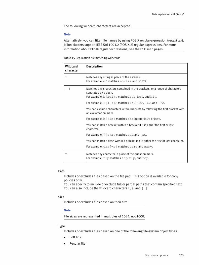
The following wildcard characters are accepted:
Note
Alternatively, you can filter file names by using POSIX regular-expression (regex) text.Isilon clusters support IEEE Std 1003.2 (POSIX.2) regular expressions. For moreinformation about POSIX regular expressions, see the BSD man pages.
Table 15 Replication file matching wildcards
Wildcardcharacter
Description
* Matches any string in place of the asterisk.For example, m* matches movies and m123.
[ ] Matches any characters contained in the brackets, or a range of charactersseparated by a dash.For example, b[aei]t matches bat, bet, and bit.
For example, 1[4-7]2 matches 142, 152, 162, and 172.
You can exclude characters within brackets by following the first bracket withan exclamation mark.
For example, b[!ie] matches bat but not bit or bet.
You can match a bracket within a bracket if it is either the first or lastcharacter.
For example, [[c]at matches cat and [at.
You can match a dash within a bracket if it is either the first or last character.
For example, car[-s] matches cars and car-.
? Matches any character in place of the question mark.For example, t?p matches tap, tip, and top.
Path
Includes or excludes files based on the file path. This option is available for copypolicies only.You can specify to include or exclude full or partial paths that contain specified text.You can also include the wildcard characters *, ?, and [ ].
Size
Includes or excludes files based on their size.
Note
File sizes are represented in multiples of 1024, not 1000.
Type
Includes or excludes files based on one of the following file-system object types:
l Soft link
l Regular file
Data replication with SyncIQ
File criteria options 265
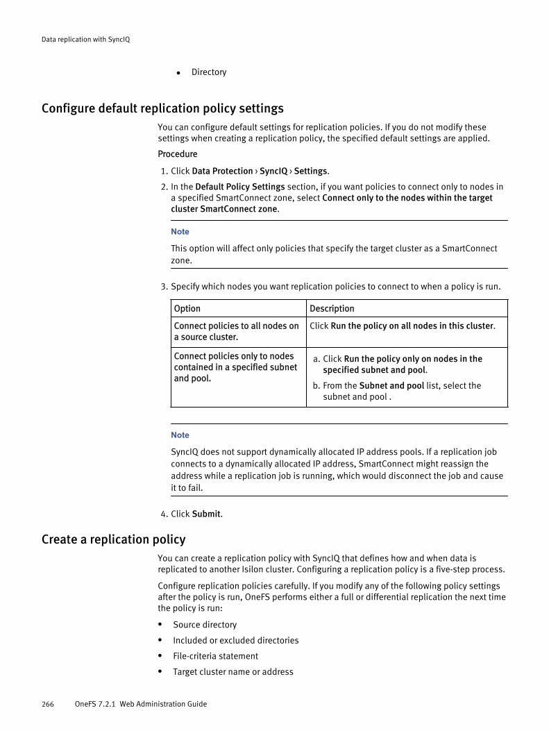
l Directory
Configure default replication policy settingsYou can configure default settings for replication policies. If you do not modify thesesettings when creating a replication policy, the specified default settings are applied.
Procedure
1. Click Data Protection > SyncIQ > Settings.
2. In the Default Policy Settings section, if you want policies to connect only to nodes ina specified SmartConnect zone, select Connect only to the nodes within the targetcluster SmartConnect zone.
Note
This option will affect only policies that specify the target cluster as a SmartConnectzone.
3. Specify which nodes you want replication policies to connect to when a policy is run.
Option Description
Connect policies to all nodes ona source cluster.
Click Run the policy on all nodes in this cluster.
Connect policies only to nodescontained in a specified subnetand pool.
a. Click Run the policy only on nodes in thespecified subnet and pool.
b. From the Subnet and pool list, select thesubnet and pool .
Note
SyncIQ does not support dynamically allocated IP address pools. If a replication jobconnects to a dynamically allocated IP address, SmartConnect might reassign theaddress while a replication job is running, which would disconnect the job and causeit to fail.
4. Click Submit.
Create a replication policyYou can create a replication policy with SyncIQ that defines how and when data isreplicated to another Isilon cluster. Configuring a replication policy is a five-step process.
Configure replication policies carefully. If you modify any of the following policy settingsafter the policy is run, OneFS performs either a full or differential replication the next timethe policy is run:
l Source directory
l Included or excluded directories
l File-criteria statement
l Target cluster name or address
Data replication with SyncIQ
266 OneFS 7.2.1 Web Administration Guide
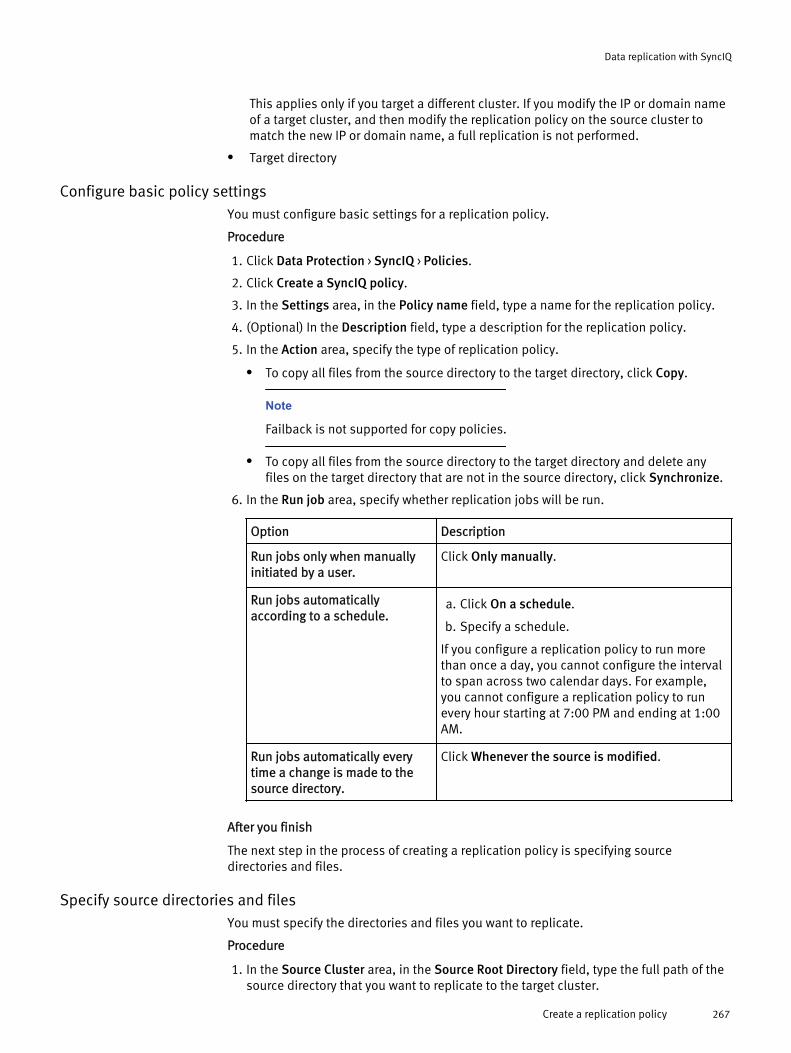
This applies only if you target a different cluster. If you modify the IP or domain nameof a target cluster, and then modify the replication policy on the source cluster tomatch the new IP or domain name, a full replication is not performed.
l Target directory
Configure basic policy settingsYou must configure basic settings for a replication policy.
Procedure
1. Click Data Protection > SyncIQ > Policies.
2. Click Create a SyncIQ policy.
3. In the Settings area, in the Policy name field, type a name for the replication policy.
4. (Optional) In the Description field, type a description for the replication policy.
5. In the Action area, specify the type of replication policy.
l To copy all files from the source directory to the target directory, click Copy.
Note
Failback is not supported for copy policies.
l To copy all files from the source directory to the target directory and delete anyfiles on the target directory that are not in the source directory, click Synchronize.
6. In the Run job area, specify whether replication jobs will be run.
Option Description
Run jobs only when manuallyinitiated by a user.
Click Only manually.
Run jobs automaticallyaccording to a schedule.
a. Click On a schedule.
b. Specify a schedule.
If you configure a replication policy to run morethan once a day, you cannot configure the intervalto span across two calendar days. For example,you cannot configure a replication policy to runevery hour starting at 7:00 PM and ending at 1:00AM.
Run jobs automatically everytime a change is made to thesource directory.
Click Whenever the source is modified.
After you finish
The next step in the process of creating a replication policy is specifying sourcedirectories and files.
Specify source directories and filesYou must specify the directories and files you want to replicate.
Procedure
1. In the Source Cluster area, in the Source Root Directory field, type the full path of thesource directory that you want to replicate to the target cluster.
Data replication with SyncIQ
Create a replication policy 267
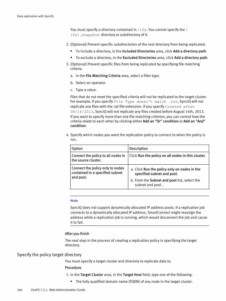
You must specify a directory contained in /ifs. You cannot specify the /ifs/.snapshot directory or subdirectory of it.
2. (Optional) Prevent specific subdirectories of the root directory from being replicated.
l To include a directory, in the Included Directories area, click Add a directory path.
l To exclude a directory, in the Excluded Directories area, click Add a directory path.
3. (Optional) Prevent specific files from being replicated by specifying file matchingcriteria.
a. In the File Matching Criteria area, select a filter type.
b. Select an operator.
c. Type a value.
Files that do not meet the specified criteria will not be replicated to the target cluster.For example, if you specify File Type doesn't match .txt, SyncIQ will notreplicate any files with the .txt file extension. If you specify Created after08/14/2013, SyncIQ will not replicate any files created before August 14th, 2013.If you want to specify more than one file matching criterion, you can control how thecriteria relate to each other by clicking either Add an "Or" condition or Add an "And"condition.
4. Specify which nodes you want the replication policy to connect to when the policy isrun.
Option Description
Connect the policy to all nodes inthe source cluster.
Click Run the policy on all nodes in this cluster.
Connect the policy only to nodescontained in a specified subnetand pool.
a. Click Run the policy only on nodes in thespecified subnet and pool.
b. From the Subnet and pool list, select thesubnet and pool .
Note
SyncIQ does not support dynamically allocated IP address pools. If a replication jobconnects to a dynamically allocated IP address, SmartConnect might reassign theaddress while a replication job is running, which would disconnect the job and causeit to fail.
After you finish
The next step in the process of creating a replication policy is specifying the targetdirectory.
Specify the policy target directoryYou must specify a target cluster and directory to replicate data to.
Procedure
1. In the Target Cluster area, in the Target Host field, type one of the following:
l The fully qualified domain name (FQDN) of any node in the target cluster.
Data replication with SyncIQ
268 OneFS 7.2.1 Web Administration Guide
l The host name of any node in the target cluster.
l The name of a SmartConnect zone in the target cluster.
l The IPv4 or IPv6 address of any node in the target cluster.
l localhostThis will replicate data to another directory on the local cluster.
Note
SyncIQ does not support dynamically allocated IP address pools. If a replication jobconnects to a dynamically allocated IP address, SmartConnect might reassign theaddress while a replication job is running, which would disconnect the job and causeit to fail.
2. In the Target Directory field, type the absolute path of the directory on the targetcluster that you want to replicate data to.
CAUTION
If you specify an existing directory on the target cluster, make sure that the directoryis not the target of another replication policy. If this is a synchronization policy, makesure that the directory is empty. All files are deleted from the target of asynchronization policy the first time that the policy is run.
If the specified target directory does not already exist on the target cluster, thedirectory is created the first time that the job is run. We recommend that you do notspecify the /ifs directory. If you specify the /ifs directory, the entire target clusteris set to a read-only state, which prevents you from storing any other data on thecluster.
If this is a copy policy, and files in the target directory share the same name as files inthe source directory, the target directory files are overwritten when the job is run.
3. If you want replication jobs to connect only to the nodes included in the SmartConnectzone specified by the target cluster, click Connect only to the nodes within the targetcluster SmartConnect Zone.
After you finish
The next step in the process of creating a replication policy is to specify policy targetsnapshot settings.
Configure policy target snapshot settingsYou can optionally specify how archival snapshots are generated on the target cluster.You can access archival snapshots the same way that you access SnapshotIQ snapshots.
SyncIQ always retains one snapshot on the target cluster to facilitate failover, regardlessof these settings.
Procedure
1. To create archival snapshots on the target cluster, in the Target Snapshots area, clickCapture snapshots on the target cluster.
2. (Optional) To modify the default alias of the last snapshot created according to thereplication policy, in the Snapshot Alias Name field, type a new alias.
Data replication with SyncIQ
Create a replication policy 269
You can specify the alias name as a snapshot naming pattern. For example, thefollowing naming pattern is valid:
%{PolicyName}-on-%{SrcCluster}-latest
The previous example produces names similar to the following:
newPolicy-on-Cluster1-latest3. (Optional) To modify the snapshot naming pattern for snapshots created according to
the replication policy, in the Snapshot Naming Pattern field, type a naming pattern.Each snapshot generated for this replication policy is assigned a name based on thispattern.
For example, the following naming pattern is valid:
%{PolicyName}-from-%{SrcCluster}-at-%H:%M-on-%m-%d-%Y
The example produces names similar to the following:
newPolicy-from-Cluster1-at-10:30-on-7-12-20124. Select one of the following options:
l Click Snapshots do not expire.
l Click Snapshots expire after... and specify an expiration period.
After you finish
The next step in the process of creating a replication policy is configuring advancedpolicy settings.
Configure advanced policy settingsYou can optionally configure advanced settings for a replication policy.
Procedure
1. (Optional) In the Worker Threads Per Node field, specify the maximum number ofconcurrent processes per node that will perform replication operations.
Note
Do not modify the default setting without consulting Isilon Technical Support.
2. (Optional) From the Log Level list, select the level of logging you want SyncIQ toperform for replication jobs.
The following log levels are valid, listed from least to most verbose:
l Fatal
l Error
l Info
l Copy
l Debug
l Trace
Replication logs are typically used for debugging purposes. If necessary, you can login to a node through the command-line interface and view the contents ofthe /var/log/isi_migrate.log file on the node.
Data replication with SyncIQ
270 OneFS 7.2.1 Web Administration Guide
Note
Notice is the recommended log level.
3. (Optional) If you want SyncIQ to perform a checksum on each file data packet that isaffected by the replication policy, select the Validate File Integrity check box.
If you enable this option, and the checksum values for a file data packet do notmatch, SyncIQ retransmits the affected packet.
4. (Optional) To modify the length of time SyncIQ retains replication reports for thepolicy, in the Keep Reports For area, specify a length of time.
After the specified expiration period has passed for a report, SyncIQ automaticallydeletes the report.
Some units of time are displayed differently when you view a report than how theywere originally entered. Entering a number of days that is equal to a correspondingvalue in weeks, months, or years results in the larger unit of time being displayed. Forexample, if you enter a value of 7 days, 1 week appears for that report after it iscreated. This change occurs because SyncIQ internally records report retention timesin seconds and then converts them into days, weeks, months, or years.
5. (Optional) Specify whether to record information about files that are deleted byreplication jobs by selecting one of the following options:
l Click Record when a synchronization deletes files or directories.
l Click Do not record when a synchronization deletes files or directories.
This option is applicable for synchronization policies only.
After you finish
The next step in the process of creating a replication policy is saving the replicationpolicy settings.
Save replication policy settingsSyncIQ does not create replication jobs for a replication policy until you save the policy.
Before you begin
Review the current settings of the replication policy. If necessary, modify the policysettings.
Procedure
1. Click Create Policy.
After you finish
You can increase the speed at which you can failback a replication policy by creating aSyncIQ domain for the source directory of the policy.
Create a SyncIQ domainYou can create a SyncIQ domain to increase the speed at which failback is performed fora replication policy. Because you can fail back only synchronization policies, it is notnecessary to create SyncIQ domains for copy policies.
Failing back a replication policy requires that a SyncIQ domain be created for the sourcedirectory. OneFS automatically creates a SyncIQ domain during the failback process.However, if you intend on failing back a replication policy, it is recommended that you
Data replication with SyncIQ
Create a SyncIQ domain 271
create a SyncIQ domain for the source directory of the replication policy while thedirectory is empty. Creating a domain for a directory that contains less data takes lesstime.
Procedure
1. Click Cluster Management > Job Operations > Job Types.
2. In the Job Types area, in the DomainMark row, from the Actions column, select StartJob.
3. In the Domain Root Path field, type the path of a source directory of a replicationpolicy.
4. From the Type of domain list, select SyncIQ.
5. Ensure that the Delete domain check box is cleared.
6. Click Start Job.
Assess a replication policyBefore running a replication policy for the first time, you can view statistics on the filesthat would be affected by the replication without transferring any files. This can be usefulif you want to preview the size of the data set that will be transferred if you run the policy.
Note
You can assess only replication policies that have never been run before.
Procedure
1. Click Data Protection > SyncIQ > Policies.
2. In the SyncIQ Policies table, in the row of a replication policy, from the Actionscolumn, select Assess Sync.
3. Click Data Protection > SyncIQ > Summary.
4. After the job completes, in the SyncIQ Recent Reports table, in the row of thereplication job, click View Details.
The report displays the total amount of data that would have been transferred in theTotal Data field.
Managing replication to remote clustersYou can manually run, view, assess, pause, resume, cancel, resolve, and reset replicationjobs that target other clusters.
After a policy job starts, you can pause the job to suspend replication activities.Afterwards, you can resume the job, continuing replication from the point where the jobwas interrupted. You can also cancel a running or paused replication job if you want tofree the cluster resources allocated for the job. A paused job reserves cluster resourceswhether or not the resources are in use. A cancelled job releases its cluster resources andallows another replication job to consume those resources. No more than five runningand paused replication jobs can exist on a cluster at a time. However, an unlimitednumber of canceled replication jobs can exist on a cluster. If a replication job remainspaused for more than a week, SyncIQ automatically cancels the job.
Data replication with SyncIQ
272 OneFS 7.2.1 Web Administration Guide
Start a replication jobYou can manually start a replication job for a replication policy at any time.
If you want to replicate data according to an existing snapshot, at the OneFS commandprompt, run the isi sync jobs start command with the --source-snapshotoption. You cannot replicate data according to snapshots generated by SyncIQ.
Procedure
1. Click Data Protection > SyncIQ > Policies.
2. In the SyncIQ Policies table, in the Actions column for a job, select Start Job.
Pause a replication jobYou can pause a running replication job and then resume the job later. Pausing areplication job temporarily stops data from being replicated, but does not free the clusterresources replicating the data.
Procedure
1. Click Data Protection > SyncIQ > Summary.
2. In the Active Jobs table, in the Actions column for a job, click Pause Running Job.
Resume a replication jobYou can resume a paused replication job.
Procedure
1. Click Data Protection > SyncIQ > Summary.
2. In the Currently Running table, in the Actions column for a job, click Resume RunningJob.
Cancel a replication jobYou can cancel a running or paused replication job. Cancelling a replication job stopsdata from being replicated and frees the cluster resources that were replicating data. Youcannot resume a cancelled replication job. To restart replication, you must start thereplication policy again.
Procedure
1. Click Data Protection > SyncIQ > Summary.
2. In the Active Jobs table, in the Actions column for a job, click Cancel Running Job.
View active replication jobsYou can view information about replication jobs that are currently running or paused.
Procedure
1. Click Data Protection > SyncIQ > Policies.
2. In the Active Jobs table, review information about active replication jobs.
Data replication with SyncIQ
Start a replication job 273
Replication job informationYou can view information about replication jobs through the Active Jobs table.
Status
The status of the job. The following job statuses are possible:
Running
The job is currently running without error.
Paused
The job has been temporarily paused.
Policy Name
The name of the associated replication policy.
Started
The time the job started.
Elapsed
How much time has elapsed since the job started.
Transferred
The number of files that have been transferred, and the total size of all transferredfiles.
Source Directory
The path of the source directory on the source cluster.
Target Host
The target directory on the target cluster.
Actions
Displays any job-related actions that you can perform.
Initiating data failover and failback with SyncIQYou can fail over from one Isilon cluster to another if, for example, a cluster becomesunavailable. You can then fail back to a primary cluster if the primary cluster becomesavailable again. You can revert failover if you decide that the failover was unnecessary, orif you failed over for testing purposes.
Note
Although you cannot fail over or fail back SmartLock directories, you can recoverSmartLock directories on a target cluster. After you recover SmartLock directories, you canmigrate them back to the source cluster.
Fail over data to a secondary clusterYou can fail over to a secondary Isilon cluster if, for example, a cluster becomesunavailable.
Before you begin
Create and successfully run a replication policy.
Data replication with SyncIQ
274 OneFS 7.2.1 Web Administration Guide
Complete the following procedure for each replication policy that you want to fail over.
Procedure
1. On the secondary Isilon cluster, click Data Protection > SyncIQ > Local Targets.
2. In the SyncIQ Local Targets table, in the row for a replication policy, from the Actionscolumn, select Allow Writes.
3. On the primary cluster, modify the replication policy so that it is set to run onlymanually.
This step will prevent the policy on the primary cluster from automatically running areplication job. If the policy on the primary cluster runs a replication job while writesare allowed to the target directory, the job will fail and the policy will be set to anunrunnable state. If this happens, modify the replication policy so that it is set to runonly manually, resolve the policy, and complete the failback process. After youcomplete the failback process, you can modify the policy to run according to aschedule again.
After you finish
Direct clients to begin accessing the secondary cluster.
Revert a failover operationFailover reversion undoes a failover operation on a secondary cluster, enabling you toreplicate data from the primary cluster to the secondary cluster again. Failover reversionis useful if the primary cluster becomes available before data is modified on thesecondary cluster or if you failed over to a secondary cluster for testing purposes.
Before you begin
Fail over a replication policy.
Reverting a failover operation does not migrate modified data back to the primary cluster.To migrate data that clients have modified on the secondary cluster, you must fail back tothe primary cluster.
Complete the following procedure for each replication policy that you want to fail over:
Procedure
1. Click Data Protection > SyncIQ > Local Targets.
2. In the SyncIQ Local Targets table, in the row for a replication policy, from the Actionscolumn, select Disallow Writes.
Fail back data to a primary clusterAfter you fail over to a secondary cluster, you can fail back to the primary cluster.
Before you begin
Fail over a replication policy.
Procedure
1. On the primary cluster, click Data Protection > SyncIQ > Policies.
2. In the SyncIQ Policies table, in the row for a replication policy, from the Actionscolumn, select Resync-prep.
SyncIQ creates a mirror policy for each replication policy on the secondary cluster.
Data replication with SyncIQ
Revert a failover operation 275

SyncIQ names mirror policies according to the following pattern:
<replication-policy-name>_mirror3. On the secondary cluster, replicate data to the primary cluster by using the mirror
policies.
You can replicate data either by manually starting the mirror policies or by modifyingthe mirror policies and specifying a schedule.
4. Prevent clients from accessing the secondary cluster and then run each mirror policyagain.
To minimize impact to clients, it is recommended that you wait until client access islow before preventing client access to the cluster.
5. On the primary cluster, click Data Protection > SyncIQ > Local Targets.
6. In the SyncIQ Local Targets table, from the Actions column, select Allow Writes foreach mirror policy.
7. On the secondary cluster, click Data Protection > SyncIQ > Policies.
8. In the SyncIQ Policies table, from the Actions column, select Resync-prep for eachmirror policy.
After you finish
Redirect clients to begin accessing the primary cluster.
Performing disaster recovery for SmartLock directoriesAlthough you cannot fail over or fail back SmartLock directories, you can recoverSmartLock directories on a target cluster. After you recover SmartLock directories, you canmigrate them back to the source cluster.
Recover SmartLock directories on a target clusterYou can recover SmartLock directories that you have replicated to a target cluster.
Before you begin
Create and successfully run a replication policy.
Complete the following procedure for each SmartLock directory that you want to recover.
Procedure
1. On the target cluster, click Data Protection > SyncIQ > Local Targets.
2. In the SyncIQ Local Targets table, in the row of the replication policy, enable writes tothe target directory of the policy.
l If the last replication job completed successfully and a replication job is notcurrently running, select Allow Writes.
l If a replication job is currently running, wait until the replication job completes,and then select Allow Writes.
l If the primary cluster became unavailable while a replication job was running,select Break Association.
3. If you clicked Break Association, restore any files that are left in an inconsistent state.
Data replication with SyncIQ
276 OneFS 7.2.1 Web Administration Guide
a. Delete all files that are not committed to a WORM state from the target directory.
b. Copy all files from the failover snapshot to the target directory.
Failover snapshots are named according to the following naming pattern:
SIQ-Failover-<policy-name>-<year>-<month>-<day>_<hour>-<minute>-<second>
Snapshots are stored in the /ifs/.snapshot directory.
4. If any SmartLock directory configuration settings, such as an autocommit time period,were specified for the source directory of the replication policy, apply those settings tothe target directory.
Because autocommit information is not transferred to the target cluster, files thatwere scheduled to be committed to a WORM state on the source cluster will not bescheduled to be committed at the same time on the target cluster. To ensure that allfiles are retained for the appropriate time period, you can commit all files in targetSmartLock directories to a WORM state. For example, the following commandautomatically commits all files in /ifs/data/smartlock to a WORM state afterone minute.
isi smartlock modify --path /ifs/data/smartlock --autocommit 1n
After you finish
Redirect clients to begin accessing the target cluster.
Migrate SmartLock directoriesYou might want to migrate SmartLock directories if you restored the directories on atarget cluster, and want to transfer those directories either back to the source cluster orto a new cluster.
Procedure
1. On a cluster, create a replication policy for each directory that you want to migrate.
The policies must meet the following requirements:
l The source directory is the SmartLock directory that you are migrating.
l The target directory is an empty SmartLock directory. The source and targetdirectories must be of the same SmartLock type. For example, if the targetdirectory is a compliance directory, the source must also be a compliancedirectory.
2. Replicate data to the target cluster by running the policies you created.
You can replicate data either by manually starting the policies or by specifying a policyschedule.
3. (Optional) To ensure that SmartLock protection is enforced for all files, commit all filesin the SmartLock source directory to a WORM state.
Because autocommit information is not transferred to the target cluster, files thatwere scheduled to be committed to a WORM state on the source cluster will not bescheduled to be committed at the same time on the target cluster. To ensure that allfiles are retained for the appropriate time period, you can commit all files in targetSmartLock directories to a WORM state.
Data replication with SyncIQ
Migrate SmartLock directories 277
For example, the following command automatically commits all files in /ifs/data/smartlock to a WORM state after one minute:
isi smartlock modify --path /ifs/data/smartlock --autocommit 1n
This step is unnecessary if you have not configured an autocommit time period for theSmartLock directory being replicated.
4. Prevent clients from accessing the source cluster and run the policy that you created.
To minimize impact to clients, it is recommended that you wait until client access islow before preventing client access to the cluster.
5. On the target cluster, click Data Protection > SyncIQ > Local Targets.
6. In the SyncIQ Local Targets table, in the row of each replication policy, from theActions column, select Allow Writes.
7. (Optional) If any SmartLock directory configuration settings, such as an autocommittime period, were specified for the source directories of the replication policies, applythose settings to the target directories.
8. (Optional) Delete the copy of your SmartLock data on the source cluster.
If the SmartLock directories are compliance directories or enterprise directories withthe privileged delete functionality permanently disabled, you cannot recover thespace consumed by the source SmartLock directories until all files are released from aWORM state. If you want to free the space before files are released from a WORMstate, contact Isilon Technical Support for information about reformatting your cluster.
Managing replication policiesYou can modify, view, enable and disable replication policies.
Modify a replication policyYou can modify the settings of a replication policy.
If you modify any of the following policy settings after a policy runs, OneFS performseither a full or differential replication the next time the policy runs:
l Source directory
l Included or excluded directories
l File-criteria statement
l Target clusterThis applies only if you target a different cluster. If you modify the IP or domain nameof a target cluster, and then modify the replication policy on the source cluster tomatch the new IP or domain name, a full replication is not performed.
l Target directory
Procedure
1. Click Data Protection > SyncIQ > Policies.
2. In the SyncIQ Policies table, in the row for a policy, click View/Edit.
3. In the View SyncIQ Policy Details dialog box, click Edit Policy.
4. Modify the settings of the replication policy, and then click Save Changes.
Data replication with SyncIQ
278 OneFS 7.2.1 Web Administration Guide
Delete a replication policyYou can delete a replication policy. Once a policy is deleted, SyncIQ no longer createsreplication jobs for the policy. Deleting a replication policy breaks the target associationon the target cluster, and allows writes to the target directory.
If you want to temporarily suspend a replication policy from creating replication jobs, youcan disable the policy, and then enable the policy again later.
Procedure
1. Click Data Protection > SyncIQ > Policies.
2. In the SyncIQ Policies table, in the row for a policy, select Delete Policy.
3. In the confirmation dialog box, click Delete.
Note
The operation will not succeed until SyncIQ can communicate with the target cluster;until then, the policy will not be removed from the SyncIQ Policies table. After theconnection between the source cluster and target cluster is reestablished, SyncIQ willdelete the policy the next time that the job is scheduled to run; if the policy isconfigured to run only manually, you must manually run the policy again. If SyncIQ ispermanently unable to communicate with the target cluster, run the isi syncpolicies delete command with the --local-only option. This will delete the
policy from the local cluster only and not break the target association on the targetcluster. For more information, see the OneFS CLI Administration Guide.
Enable or disable a replication policyYou can temporarily suspend a replication policy from creating replication jobs, and thenenable it again later.
Note
If you disable a replication policy while an associated replication job is running, therunning job is not interrupted. However, the policy will not create another job until thepolicy is enabled.
Procedure
1. Click Data Protection > SyncIQ > Policies.
2. In the SyncIQ Policies table, in the row for a replication policy, select either EnablePolicy or Disable Policy.
If neither Enable Policy nor Disable Policy appears, verify that a replication job is notrunning for the policy. If an associated replication job is not running, ensure that theSyncIQ license is active on the cluster.
View replication policiesYou can view information about replication policies.
Procedure
1. Click Data Protection > SyncIQ > Policies.
Data replication with SyncIQ
Delete a replication policy 279
2. In the SyncIQ Policies table, review information about replication policies.
Replication policy informationYou can view information about replication policies through the SyncIQ Policies table.
Policy Name
The name of the policy.
State
Whether the policy is enabled or disabled.
Last Known Good
When the last successful job ran.
Schedule
When the next job is scheduled to run. A value of Manual indicates that the job canbe run only manually. A value of When source is modified indicates that the job willbe run whenever changes are made to the source directory.
Source Directory
The path of the source directory on the source cluster.
Target Host : Directory
The IP address or fully qualified domain name of the target cluster and the full pathof the target directory.
Actions
Any policy-related actions that you can perform.
Replication policy settingsYou configure replication policies to run according to replication policy settings.
Policy name
The name of the policy.
Description
Describes the policy. For example, the description might explain the purpose orfunction of the policy.
Enabled
Determines whether the policy is enabled.
Action
Determines the how the policy replicates data. All policies copy files from the sourcedirectory to the target directory and update files in the target directory to match fileson the source directory. The action determines how deleting a file on the sourcedirectory affects the target. The following values are valid:
Copy
If a file is deleted in the source directory, the file is not deleted in the targetdirectory.
Data replication with SyncIQ
280 OneFS 7.2.1 Web Administration Guide
Synchronize
Deletes files in the target directory if they are no longer present on the source.This ensures that an exact replica of the source directory is maintained on thetarget cluster.
Run job
Determines whether jobs are run automatically according to a schedule or only whenmanually specified by a user.
Last Successful Run
Displays the last time that a replication job for the policy completed successfully.
Last Started
Displays the last time that the policy was run.
Source Root Directory
The full path of the source directory. Data is replicated from the source directory tothe target directory.
Included Directories
Determines which directories are included in replication. If one or more directoriesare specified by this setting, any directories that are not specified are not replicated.
Excluded Directories
Determines which directories are excluded from replication. Any directories specifiedby this setting are not replicated.
File Matching Criteria
Determines which files are excluded from replication. Any files that do not meet thespecified criteria are not replicated.
Restrict Source Nodes
Determines whether the policy can run on all nodes on the source cluster or run onlyon specific nodes.
Target Host
The IP address or fully qualified domain name of the target cluster.
Target Directory
The full path of the target directory. Data is replicated to the target directory from thesource directory.
Restrict Target Nodes
Determines whether the policy can connect to all nodes on the target cluster or canconnect only to specific nodes.
Capture Snapshots
Determines whether archival snapshots are generated on the target cluster.
Snapshot Alias Name
Specifies an alias for the latest archival snapshot taken on the target cluster.
Snapshot Naming Pattern
Specifies how archival snapshots are named on the target cluster.
Data replication with SyncIQ
Replication policy settings 281
Snapshot Expiration
Specifies how long archival snapshots are retained on the target cluster before theyare automatically deleted by the system.
Workers Threads Per Node
Specifies the number of workers per node that are generated by OneFS to performeach replication job for the policy.
Log Level
Specifies the amount of information that is recorded for replication jobs.More verbose options include all information from less verbose options. Thefollowing list describes the log levels from least to most verbose:
l Fatal
l Error
l Notice
l Info
l Copy
l Debug
l Trace
Replication logs are typically used for debugging purposes. If necessary, you can login to a node through the command-line interface and view the contents ofthe /var/log/isi_migrate.log file on the node.
Note
Notice is the recommended log level.
Validate File Integrity
Determines whether OneFS performs a checksum on each file data packet that isaffected by a replication job. If a checksum value does not match, OneFS retransmitsthe affected file data packet.
Keep Reports For
Specifies how long replication reports are kept before they are automatically deletedby OneFS.
Log Deletions on Synchronization
Determines whether OneFS records when a synchronization job deletes files ordirectories on the target cluster.
The following replication policy fields are available only through the OneFS command-lineinterface.
Source Subnet
Specifies whether replication jobs connect to any nodes in the cluster or if jobs canconnect only to nodes in a specified subnet.
Source Pool
Specifies whether replication jobs connect to any nodes in the cluster or if jobs canconnect only to nodes in a specified pool.
Data replication with SyncIQ
282 OneFS 7.2.1 Web Administration Guide
Password Set
Specifies a password to access the target cluster.
Report Max Count
Specifies the maximum number of replication reports that are retained for thispolicy.
Target Compare Initial Sync
Determines whether full or differential replications are performed for this policy. Fullor differential replications are performed the first time a policy is run and after apolicy is reset.
Source Snapshot Archive
Determines whether snapshots generated for the replication policy on the sourcecluster are deleted when the next replication policy is run. Enabling archival sourcesnapshots does not require you to activate the SnapshotIQ license on the cluster.
Source Snapshot Pattern
If snapshots generated for the replication policy on the source cluster are retained,renames snapshots according to the specified rename pattern.
Source Snapshot Expiration
If snapshots generated for the replication policy on the source cluster are retained,specifies an expiration period for the snapshots.
Restrict Target Network
Determines whether replication jobs connect only to nodes in a given SmartConnectzone. This setting applies only if the Target Host is specified as a SmartConnectzone.
Target Detect Modifications
Determines whether SyncIQ checks the target directory for modifications beforereplicating files. By default, SyncIQ always checks for modifications.
Note
Disabling this option could result in data loss. It is recommended that you consultIsilon Technical Support before disabling this option.
Resolve
Determines whether you can manually resolve the policy if a replication jobencounters an error.
Managing replication to the local clusterYou can interrupt replication jobs that target the local cluster.
You can cancel a currently running job that targets the local cluster, or you can break theassociation between a policy and its specified target. Breaking a source and targetcluster association causes SyncIQ to perform a full replication the next time the policy isrun.
Data replication with SyncIQ
Managing replication to the local cluster 283
Cancel replication to the local clusterYou can cancel a replication job that is targeting the local cluster.
Procedure
1. Click Data Protection > SyncIQ > Local Targets.
2. In the SyncIQ Local Targets table, specify whether to cancel a specific replication jobor all replication jobs targeting the local cluster.
l To cancel a specific job, in the row for a replication job, select Cancel Running Job.
l To cancel all jobs targeting the local cluster, select the check box to the left ofPolicy Name and then select Cancel Selection from the Select a bulk action list.
Break local target associationYou can break the association between a replication policy and the local cluster.Breaking the target association will allow writes to the target directory but will alsorequire you to reset the replication policy before you can run the policy again.
CAUTION
After a replication policy is reset, SyncIQ performs a full or differential replication thenext time the policy is run. Depending on the amount of data being replicated, a full ordifferential replication can take a very long time to complete.
Procedure
1. Click Data Protection > SyncIQ > Local Targets.
2. In the SyncIQ Local Targets table, in the row for a replication policy, select BreakAssociation.
3. In the Confirm dialog box, click Yes.
View replication policies targeting the local clusterYou can view information about replication policies that are currently replicating data tothe local cluster.
Procedure
1. Click Data Protection > SyncIQ > Local Targets.
2. In the SyncIQ Local Targets table, view information about replication policies.
Remote replication policy informationYou can view information about replication policies that are currently targeting the localcluster.
The following information is displayed in the SyncIQ Local Targets table:
ID
The ID of the replication policy.
Policy Name
The name of the replication policy.
Source Host
The name of the source cluster.
Data replication with SyncIQ
284 OneFS 7.2.1 Web Administration Guide

Source Cluster GUID
The GUID of the source cluster.
Coordinator IP
The IP address of the node on the source cluster that is acting as the job coordinator.
Updated
The time when data about the policy or job was last collected from the sourcecluster.
Target Path
The path of the target directory on the target cluster.
Status
The current status of the replication job.
Actions
Displays any job-related actions that you can perform.
Managing replication performance rulesYou can manage the impact of replication on cluster performance by creating rules thatlimit the network traffic created and the rate at which files are sent by replication jobs.
Create a network traffic ruleYou can create a network traffic rule that limits the amount of network traffic thatreplication policies are allowed to generate during a specified time period.
Procedure
1. Click Data Protection > SyncIQ > Performance Rules.
2. Click Create a SyncIQ Performance Rule.
3. From the Rule Type list, select Bandwidth.
4. In the Limit field, specify the maximum number of kilobits per second that replicationpolicies are allowed to send.
5. In the Schedule area, specify the time and days of the week that you want to apply therule.
6. Click Create Performance Rule.
Create a file operations ruleYou can create a file-operations rule that limits the number of files that replication jobscan send per second.
Procedure
1. Click Data Protection > SyncIQ > Performance Rules.
2. Click Create a SyncIQ Performance Rule.
3. From the Rule Type list, select Bandwidth.
4. In the Limit field, specify the maximum number of files per second that replicationpolicies are allowed to send.
5. In the Schedule area, specify the time and days of the week that you want to apply therule.
Data replication with SyncIQ
Managing replication performance rules 285

6. Click Create Performance Rule.
Modify a performance ruleYou can modify a performance rule.
Procedure
1. Click Data Protection > SyncIQ > Performance Rules.
2. In the SyncIQ Performance Rules, in the row for the rule you want to modify, clickView/Edit.
3. Click Edit Performance Rule.
4. Modify rule settings, and then click Save Changes.
Delete a performance ruleYou can delete a performance rule.
Procedure
1. Click Data Protection > SyncIQ > Performance Rules.
2. In the SyncIQ Performance Rules table, in the row for the rule you want to delete,select Delete Rule.
3. In the Confirm Delete dialog box, click Delete.
Enable or disable a performance ruleYou can disable a performance rule to temporarily prevent the rule from being enforced.You can also enable a performance rule after it has been disabled.
Procedure
1. Click Data Protection > SyncIQ > Performance Rules.
2. In the SyncIQ Performance Rules table, in the row for a rule you want to enable ordisable, select either Enable Rule or Disable Rule.
View performance rulesYou can view information about replication performance rules.
Procedure
1. Click Data Protection > SyncIQ > Performance Rules.
2. In the SyncIQ Performance Rules table, view information about performance rules.
Data replication with SyncIQ
286 OneFS 7.2.1 Web Administration Guide
Managing replication reportsIn addition to viewing replication reports, you can configure how long reports are retainedon the cluster. You can also delete any reports that have passed their expiration period.
Configure default replication report settingsYou can configure the default amount of time that SyncIQ retains replication reports for.You can also configure the maximum number of reports that SyncIQ retains for eachreplication policy.
Procedure
1. Click Data Protection > SyncIQ > Settings.
2. In the Report Settings area, in the Keep Reports For area, specify how long you wantto retain replication reports for.
After the specified expiration period has passed for a report, SyncIQ automaticallydeletes the report.
Some units of time are displayed differently when you view a report than how youoriginally enter them. Entering a number of days that is equal to a correspondingvalue in weeks, months, or years results in the larger unit of time being displayed. Forexample, if you enter a value of 7 days, 1 week appears for that report after it iscreated. This change occurs because SyncIQ internally records report retention timesin seconds and then converts them into days, weeks, months, or years for display.
3. In the Number of Reports to Keep Per Policy field, type the maximum number ofreports you want to retain at a time for a replication policy.
4. Click Submit.
Delete replication reportsReplication reports are routinely deleted by SyncIQ after the expiration date for thereports has passed. SyncIQ also deletes reports after the number of reports exceeds thespecified limit. Excess reports are periodically deleted by SyncIQ; however, you canmanually delete all excess replication reports at any time. This procedure is availableonly through the command-line interface (CLI).
Procedure
1. Open a secure shell (SSH) connection to any node in the cluster and log in.
2. Delete excess replication reports by running the following command:
isi sync reports rotate
View replication reportsYou can view replication reports and subreports.
Procedure
1. Click Data Protection > SyncIQ > Reports.
2. In the SyncIQ Reports table, in the row for a report, click View Details.
If a report is composed of subreports, the report is displayed as a folder. Subreportsare displayed as files within report folders.
Data replication with SyncIQ
Managing replication reports 287
Replication report informationYou can view information about replication jobs through the Reports table.
Policy Name
The name of the associated policy for the job. You can view or edit settings for thepolicy by clicking the policy name.
Status
Displays the status of the job. The following job statuses are possible:
RunningThe job is currently running without error.
PausedThe job has been temporarily paused.
FinishedThe job completed successfully.
FailedThe job failed to complete.
Started
Indicates when the job started.
Ended
Indicates when the job ended.
Duration
Indicates how long the job took to complete.
Transferred
The total number of files that were transferred during the job run, and the total sizeof all transferred files. For assessed policies, Assessment appears.
Source Directory
The path of the source directory on the source cluster.
Target Host
The IP address or fully qualified domain name of the target cluster.
Action
Displays any report-related actions that you can perform.
Managing failed replication jobsIf a replication job fails due to an error, SyncIQ might disable the correspondingreplication policy. For example SyncIQ might disable a replication policy if the IP orhostname of the target cluster is modified. If a replication policy is disabled, the policycannot be run.
To resume replication for a disabled policy, you must either fix the error that caused thepolicy to be disabled, or reset the replication policy. It is recommended that you attemptto fix the issue rather than reset the policy. If you believe you have fixed the error, youcan return the replication policy to an enabled state by resolving the policy. You can then
Data replication with SyncIQ
288 OneFS 7.2.1 Web Administration Guide

run the policy again to test whether the issue was fixed. If you are unable to fix the issue,you can reset the replication policy. However, resetting the policy causes a full ordifferential replication to be performed the next time the policy is run.
Note
Depending on the amount of data being synchronized or copied, a full and differentialreplications can take a very long time to complete.
Resolve a replication policyIf SyncIQ disables a replication policy due to a replication error, and you fix the issue thatcaused the error, you can resolve the replication policy. Resolving a replication policyenables you to run the policy again. If you cannot resolve the issue that caused the error,you can reset the replication policy.
Procedure
1. Click Data Protection > SyncIQ > Policies.
2. In the Policies table, in the row for a policy, select Resolve.
Reset a replication policyIf a replication job encounters an error that you cannot resolve, you can reset thecorresponding replication policy. Resetting a policy causes OneFS to perform a full ordifferential replication the next time the policy is run. Resetting a replication policydeletes the latest snapshot generated for the policy on the source cluster.
CAUTION
Depending on the amount of data being replicated, a full or differential replication cantake a very long time to complete. Reset a replication policy only if you cannot fix theissue that caused the replication error. If you fix the issue that caused the error, resolvethe policy instead of resetting the policy.
Procedure
1. Click Data Protection > SyncIQ > Policies.
2. In the SyncIQ Policies table, in the row for a policy, select Reset Sync State.
Perform a full or differential replicationAfter you reset a replication policy, you must perform either a full or differentialreplication.
Before you begin
Reset a replication policy.
Procedure
1. Open a secure shell (SSH) connection to any node in the cluster and log in through theroot or compliance administrator account.
2. Specify the type of replication you want to perform by running the isi syncpolicies modify command.
l To perform a full replication, disable the --target-compare-initial-syncoption.
Data replication with SyncIQ
Resolve a replication policy 289
For example, the following command disables differential synchronization fornewPolicy:
isi sync policies modify newPolicy \--target-compare-initial-sync false
l To perform a differential replication, enable the --target-compare-initial-sync option.
For example, the following command enables differential synchronization fornewPolicy:
isi sync policies modify newPolicy \--target-compare-initial-sync true
3. Run the policy by running the isi sync jobs start command.
For example, the following command runs newPolicy:
isi sync jobs start newPolicy
Managing changelistsYou can create and view changelists that describe what data was modified by areplication job. Changelists are most commonly accessed by applications through theOneFS Platform API.
To create a changelist, you must enable changelists for a replication policy. If changelistsare enabled for a policy, SyncIQ does not automatically delete the repstate filesgenerated by the policy; if changelists are not enabled for a policy, SyncIQ automaticallydeletes the repstate files after the corresponding replication jobs complete. SyncIQgenerates one repstate file for each replication job. Because a large amount of repstatefiles can consume a large amount of disk space, it is recommended that you do notenable changelists for a policy unless it is necessary for your workflow.
If changelists are enabled for a policy, SyncIQ does not automatically delete sourcecluster snapshots for the policy. To create a changelist, you must have access to twoconsecutive snapshots and an associated repstate generated by a replication policy.
Create a changelistYou can create a changelist to view what data was modified by a replication job.
Before you begin
Through the OneFS command line, enable changelists for a replication policy, and thenrun the policy at least twice. The following command enables changelists for newPolicy:
isi sync policies modify newPolicy --changelist true
Note
You can enable changelists only through the command-line interface (CLI).
Procedure
1. (Optional) Record the IDs of the snapshots generated by the replication policy.
a. Click File System Management > SnapshotIQ > Snapshots.
b. In the row of the snapshots that were created for the replication policies that youwant to create a change list for, click, View Details and record the IDs of thesnapshots
Data replication with SyncIQ
290 OneFS 7.2.1 Web Administration Guide
The snapshots must have been generated sequentially for the same replicationpolicy. Changelist snapshots are generated according to the following snapshotnaming convention:
SIQ-Changelist-<policy-name>-<date>
If source-archival snapshots are enabled for the policy, the change-list snapshotsare named according to the naming convention specified by the policy.
2. Click Cluster Management > Job Operations > Job Types.
3. In the Job Types area, in the ChangelistCreate row, from the Actions column, selectStart Job.
4. In the Older Snapshot ID field, type the ID of the snapshot generated when thereplication policy started.
5. In the Newer Snapshot ID field, type the ID of the snapshot generated when thereplication policy ended.
6. (Optional) If you want to recreate the changelist later, select Retain the replicationrecord after a changelist is created. If you do not select this option, the repstate fileused to generate the changelist is deleted after the changelist is created.
7. Click Start Job.
View a changelistYou can view a changelist that describes what data was modified by a replication job.This procedure is available only through the command-line interface (CLI).
Procedure
1. View the IDs of changelists by running the following command:
isi_changelist_mod -l
Changelist IDs include the IDs of both snapshots used to create the changelist. IfOneFS is still in the process of creating a changelist, inprog is appended to thechangelist ID.
2. (Optional) View all contents of a changelist by running the isi_changelist_modcommand with the -a option.
The following command displays the contents of a changelist named 2_6:
isi_changelist_mod -a 2_63. View a specific changelist entry by running the isi_changelist_mod command
with the -g option.
The following command displays an entry with a LIN of 1003402c3 from a changelistnamed 2_6:
isi_changelist_mod -g 2_6 1003402c3
Data replication with SyncIQ
View a changelist 291
Changelist informationYou can view the information contained in changelists.
Note
The information contained in changelists is meant to be consumed by applicationsthrough the OneFS Platform API. The information might be less useful when consumedthrough the command-line interface (CLI).
The following information is displayed in the output of the isi_changelist_modcommand:
lin
The LIN of the changelist entry. Metadata entries are assigned a LIN of 1.
entry_type
The type of changelist entry. The field is set to either metadata or file.
size
The total size of the changelist entry, in bytes.
reserved
This field is not currently used by changelists.
root_path
The root path of the snapshots used to create the changelist.
owning_job_id
The ID of the ChangelistCreate job that created the changelist.
num_cl_entries
The number of changelist entries in the changelist.
root_path_size
The total size of the null-terminated UTF-8 string that contains the root path of thesnapshots, in bytes.
root_path_offset
The number of bytes between the start of the changelist entry structure and the null-terminated UTF-8 string that contains the root path of the snapshots.
path
The path, relative to the root path, of the file or directory that was modified orremoved.
type
If an item was modified, describes the type of item that was modified. The followingtypes of items might have been modified:
regular
A regular file was modified.
directory
A directory was modified.
Data replication with SyncIQ
292 OneFS 7.2.1 Web Administration Guide

symlink
A symbolic link was modified.
fifo
A first-in-first-out (FIFO) queue was modified.
socket
A Unix domain socket was modified.
char device
A character device was modified.
block device
A block device was modified.
unknown
An unknown type of file was modified.
If any type of item was removed, this field is set to (REMOVED).
size
The size of the item that was modified, in bytes. If an item was removed, this field isset to 0.
path_size
The total size of the null-terminated UTF-8 string that contains the path, relative tothe root path, of the file or directory that was modified or removed, in bytes.
path_offset
The number of bytes between the start of the changelist entry structure and the path,relative to the root path, of the file or directory that was modified or removed.
atime
The POSIX timestamp of when the item was last accessed.
atimensec
The number of nanoseconds past the atime that the item was last accessed.
ctime
The POSIX timestamp of when the item was last changed.
ctimensec
The number of nanoseconds past the ctime that the item was last changed.
mtime
The POSIX timestamp of when the item was last modified.
mtimensec
The number of nanoseconds past the mtime that the item was last modified.
Data replication with SyncIQ
Changelist information 293

Data replication with SyncIQ
294 OneFS 7.2.1 Web Administration Guide

CHAPTER 15
Data layout with FlexProtect
This section contains the following topics:
l FlexProtect overview............................................................................................296l File striping......................................................................................................... 296l Requested data protection.................................................................................. 296l FlexProtect data recovery.....................................................................................297l Requesting data protection................................................................................. 298l Requested protection settings.............................................................................298l Requested protection disk space usage.............................................................. 299
Data layout with FlexProtect 295
FlexProtect overviewAn Isilon cluster is designed to continuously serve data, even when one or morecomponents simultaneously fail. OneFS ensures data availability by striping or mirroringdata across the cluster. If a cluster component fails, data stored on the failed componentis available on another component. After a component failure, lost data is restored onhealthy components by the FlexProtect proprietary system.
Data protection is specified at the file level, not the block level, enabling the system torecover data quickly. Because all data, metadata, and parity information is distributedacross all nodes, the cluster does not require a dedicated parity node or drive. Thisensures that no single node limits the speed of the rebuild process.
File stripingOneFS uses the internal network to automatically allocate and stripe data across nodesand disks in the cluster. OneFS protects data as the data is being written. No separateaction is necessary to stripe data.
OneFS breaks files into smaller logical chunks called stripes before writing the files todisk; the size of each file chunk is referred to as the stripe unit size. Each OneFS block is8 KB, and a stripe unit consists of 16 blocks, for a total of 128 KB per stripe unit. During awrite, OneFS breaks data into stripes and then logically places the data in a stripe unit.As OneFS stripes data across the cluster, OneFS fills the stripe unit according to thenumber of nodes and protection level.
OneFS can continuously reallocate data and make storage space more usable andefficient. As the cluster size increases, OneFS stores large files more efficiently.
Requested data protectionThe requested protection of data determines the amount of redundant data created onthe cluster to ensure that data is protected against component failures. OneFS enablesyou to modify the requested protection in real time while clients are reading and writingdata on the cluster.
OneFS provides several data protection settings. You can modify these protectionsettings at any time without rebooting or taking the cluster or file system offline. Whenplanning your storage solution, keep in mind that increasing the requested protectionreduces write performance and requires additional storage space for the increasednumber of nodes.
OneFS uses the Reed Solomon algorithm for N+M protection. In the N+M data protectionmodel, N represents the number of data-stripe units, and M represents the number ofsimultaneous node or drive failures—or a combination of node and drive failures—thatthe cluster can withstand without incurring data loss. N must be larger than M.
In addition to N+M data protection, OneFS also supports data mirroring from 2x to 8x,allowing from two to eight mirrors of data. In terms of overall cluster performance andresource consumption, N+M protection is often more efficient than mirrored protection.However, because read and write performance is reduced for N+M protection, datamirroring might be faster for data that is updated often and is small in size. Datamirroring requires significant overhead and might not always be the best data-protectionmethod. For example, if you enable 3x mirroring, the specified content is duplicated threetimes on the cluster; depending on the amount of content mirrored, this can consume asignificant amount of storage space.
Data layout with FlexProtect
296 OneFS 7.2.1 Web Administration Guide
FlexProtect data recoveryOneFS uses the FlexProtect proprietary system to detect and repair files and directoriesthat are in a degraded state due to node or drive failures.
OneFS protects data in the cluster based on the configured protection policy. OneFSrebuilds failed disks, uses free storage space across the entire cluster to further preventdata loss, monitors data, and migrates data off of at-risk components.
OneFS distributes all data and error-correction information across the cluster and ensuresthat all data remains intact and accessible even in the event of simultaneous componentfailures. Under normal operating conditions, all data on the cluster is protected againstone or more failures of a node or drive. However, if a node or drive fails, the clusterprotection status is considered to be in a degraded state until the data is protected byOneFS again. OneFS reprotects data by rebuilding data in the free space of the cluster.While the protection status is in a degraded state, data is more vulnerable to data loss.
Because data is rebuilt in the free space of the cluster, the cluster does not require adedicated hot-spare node or drive in order to recover from a component failure. Becausea certain amount of free space is required to rebuild data, it is recommended that youreserve adequate free space through the virtual hot spare feature.
As you add more nodes, the cluster gains more CPU, memory, and disks to use duringrecovery operations. As a cluster grows larger, data restriping operations become faster.
SmartfailOneFS protects data stored on failing nodes or drives through a process calledsmartfailing.
During the smartfail process, OneFS places a device into quarantine. Data stored onquarantined devices is read only. While a device is quarantined, OneFS reprotects thedata on the device by distributing the data to other devices. After all data migration iscomplete, OneFS logically removes the device from the cluster, the cluster logicallychanges its width to the new configuration, and the node or drive can be physicallyreplaced.
OneFS smartfails devices only as a last resort. Although you can manually smartfailnodes or drives, it is recommended that you first consult Isilon Technical Support.
Occasionally a device might fail before OneFS detects a problem. If a drive fails withoutbeing smartfailed, OneFS automatically starts rebuilding the data to available free spaceon the cluster. However, because a node might recover from a failure, if a node fails,OneFS does not start rebuilding data unless the node is logically removed from thecluster.
Node failuresBecause node loss is often a temporary issue, OneFS does not automatically startreprotecting data when a node fails or goes offline. If a node reboots, the file system doesnot need to be rebuilt because it remains intact during the temporary failure.
If you configure N+1 data protection on a cluster, and one node fails, all of the data is stillaccessible from every other node in the cluster. If the node comes back online, the noderejoins the cluster automatically without requiring a full rebuild.
To ensure that data remains protected, if you physically remove a node from the cluster,you must also logically remove the node from the cluster. After you logically remove anode, the node automatically reformats its own drives, and resets itself to the factory
Data layout with FlexProtect
FlexProtect data recovery 297
default settings. The reset occurs only after OneFS has confirmed that all data has beenreprotected. You can logically remove a node using the smartfail process. It is importantthat you smartfail nodes only when you want to permanently remove a node from thecluster.
If you remove a failed node before adding a new node, data stored on the failed nodemust be rebuilt in the free space in the cluster. After the new node is added, OneFSdistributes the data to the new node. It is more efficient to add a replacement node to thecluster before failing the old node because OneFS can immediately use the replacementnode to rebuild the data stored on the failed node.
Requesting data protectionYou can specify the protection of a file or directory by setting its requested protection.This flexibility enables you to protect distinct sets of data at higher than default levels.
Requested protection of data is calculated by OneFS and set automatically on storagepools within your cluster. The default setting is referred to as suggested protection, andprovides the optimal balance between data protection and storage efficiency. Forexample, a suggested protection of N+2:1 means that two drives or one node can failwithout causing any data loss.
For best results, we recommend that you accept at least the suggested protection for dataon your cluster. You can always specify a higher protection level than suggestedprotection on critical files, directories, or node pools.
OneFS allows you to request protection that the cluster is currently incapable ofmatching. If you request an unmatchable protection, the cluster will continue trying tomatch the requested protection until a match is possible. For example, in a four-nodecluster, you might request a mirror protection of 5x. In this example, OneFS would mirrorthe data at 4x until you added a fifth node to the cluster, at which point OneFS wouldreprotect the data at 5x.
If you set requested protection to a level below suggested protection, OneFS warns you ofthis condition.
Note
For 4U Isilon IQ X-Series and NL-Series nodes, and IQ 12000X/EX 12000 combinationplatforms, the minimum cluster size of three nodes requires a minimum protection of N+2:1.
Requested protection settingsRequested protection settings determine the level of hardware failure that a cluster canrecover from without suffering data loss.
Requested protectionsetting
Minimum number ofnodes required
Definition
[+1n] 3 The cluster can recover from onedrive or node failure withoutsustaining any data loss.
[+2d:1n] 3 The cluster can recover from twosimultaneous drive failures or onenode failure without sustaining anydata loss.
Data layout with FlexProtect
298 OneFS 7.2.1 Web Administration Guide
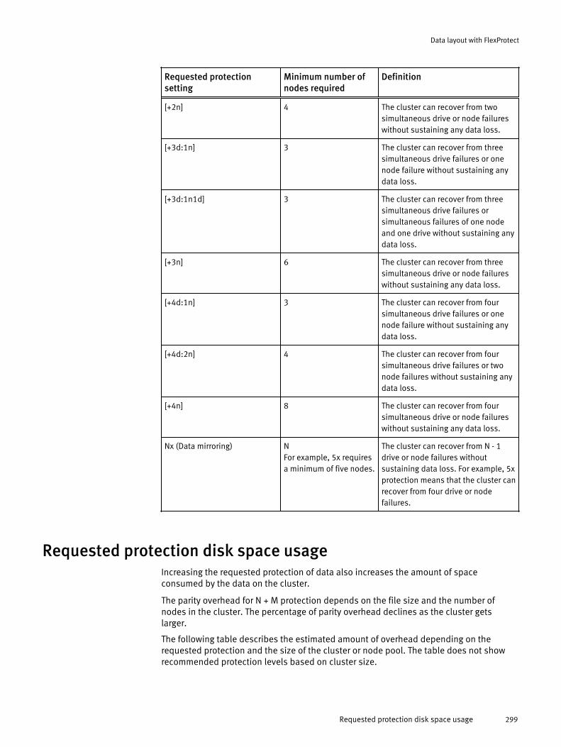
Requested protectionsetting
Minimum number ofnodes required
Definition
[+2n] 4 The cluster can recover from twosimultaneous drive or node failureswithout sustaining any data loss.
[+3d:1n] 3 The cluster can recover from threesimultaneous drive failures or onenode failure without sustaining anydata loss.
[+3d:1n1d] 3 The cluster can recover from threesimultaneous drive failures orsimultaneous failures of one nodeand one drive without sustaining anydata loss.
[+3n] 6 The cluster can recover from threesimultaneous drive or node failureswithout sustaining any data loss.
[+4d:1n] 3 The cluster can recover from foursimultaneous drive failures or onenode failure without sustaining anydata loss.
[+4d:2n] 4 The cluster can recover from foursimultaneous drive failures or twonode failures without sustaining anydata loss.
[+4n] 8 The cluster can recover from foursimultaneous drive or node failureswithout sustaining any data loss.
Nx (Data mirroring) NFor example, 5x requiresa minimum of five nodes.
The cluster can recover from N - 1drive or node failures withoutsustaining data loss. For example, 5xprotection means that the cluster canrecover from four drive or nodefailures.
Requested protection disk space usageIncreasing the requested protection of data also increases the amount of spaceconsumed by the data on the cluster.
The parity overhead for N + M protection depends on the file size and the number ofnodes in the cluster. The percentage of parity overhead declines as the cluster getslarger.
The following table describes the estimated amount of overhead depending on therequested protection and the size of the cluster or node pool. The table does not showrecommended protection levels based on cluster size.
Data layout with FlexProtect
Requested protection disk space usage 299
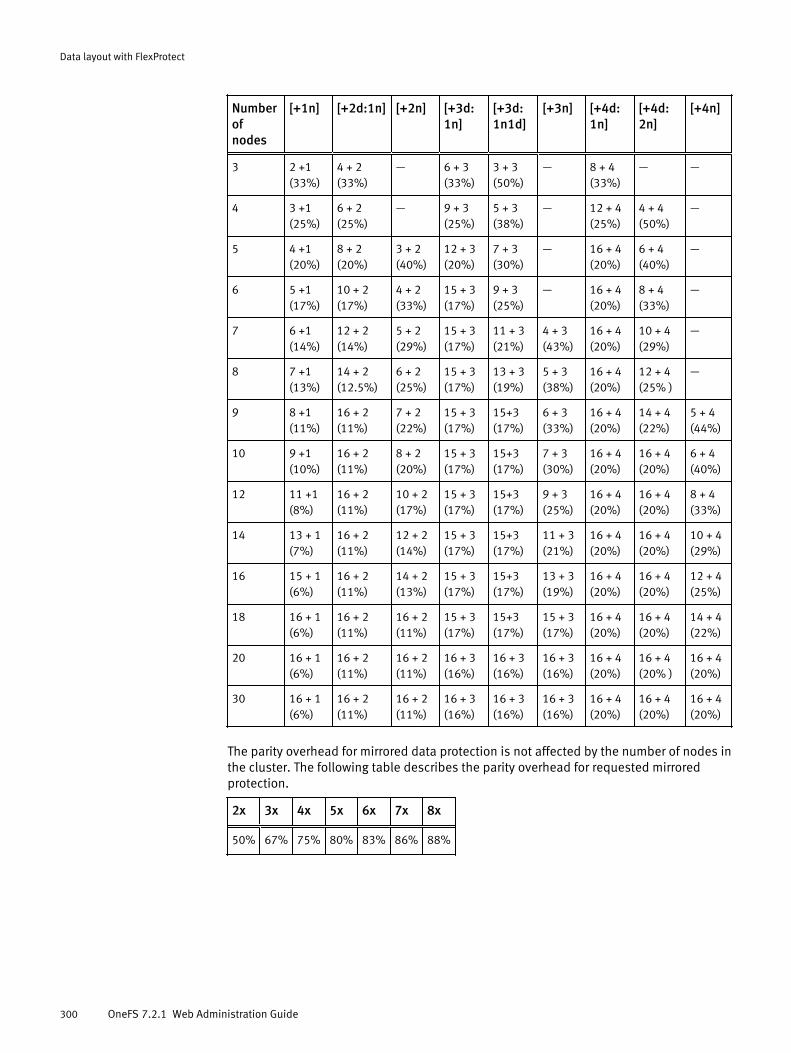
Numberofnodes
[+1n] [+2d:1n] [+2n] [+3d:1n]
[+3d:1n1d]
[+3n] [+4d:1n]
[+4d:2n]
[+4n]
3 2 +1(33%)
4 + 2(33%)
— 6 + 3(33%)
3 + 3(50%)
— 8 + 4(33%)
— —
4 3 +1(25%)
6 + 2(25%)
— 9 + 3(25%)
5 + 3(38%)
— 12 + 4(25%)
4 + 4(50%)
—
5 4 +1(20%)
8 + 2(20%)
3 + 2(40%)
12 + 3(20%)
7 + 3(30%)
— 16 + 4(20%)
6 + 4(40%)
—
6 5 +1(17%)
10 + 2(17%)
4 + 2(33%)
15 + 3(17%)
9 + 3(25%)
— 16 + 4(20%)
8 + 4(33%)
—
7 6 +1(14%)
12 + 2(14%)
5 + 2(29%)
15 + 3(17%)
11 + 3(21%)
4 + 3(43%)
16 + 4(20%)
10 + 4(29%)
—
8 7 +1(13%)
14 + 2(12.5%)
6 + 2(25%)
15 + 3(17%)
13 + 3(19%)
5 + 3(38%)
16 + 4(20%)
12 + 4(25% )
—
9 8 +1(11%)
16 + 2(11%)
7 + 2(22%)
15 + 3(17%)
15+3(17%)
6 + 3(33%)
16 + 4(20%)
14 + 4(22%)
5 + 4(44%)
10 9 +1(10%)
16 + 2(11%)
8 + 2(20%)
15 + 3(17%)
15+3(17%)
7 + 3(30%)
16 + 4(20%)
16 + 4(20%)
6 + 4(40%)
12 11 +1(8%)
16 + 2(11%)
10 + 2(17%)
15 + 3(17%)
15+3(17%)
9 + 3(25%)
16 + 4(20%)
16 + 4(20%)
8 + 4(33%)
14 13 + 1(7%)
16 + 2(11%)
12 + 2(14%)
15 + 3(17%)
15+3(17%)
11 + 3(21%)
16 + 4(20%)
16 + 4(20%)
10 + 4(29%)
16 15 + 1(6%)
16 + 2(11%)
14 + 2(13%)
15 + 3(17%)
15+3(17%)
13 + 3(19%)
16 + 4(20%)
16 + 4(20%)
12 + 4(25%)
18 16 + 1(6%)
16 + 2(11%)
16 + 2(11%)
15 + 3(17%)
15+3(17%)
15 + 3(17%)
16 + 4(20%)
16 + 4(20%)
14 + 4(22%)
20 16 + 1(6%)
16 + 2(11%)
16 + 2(11%)
16 + 3(16%)
16 + 3(16%)
16 + 3(16%)
16 + 4(20%)
16 + 4(20% )
16 + 4(20%)
30 16 + 1(6%)
16 + 2(11%)
16 + 2(11%)
16 + 3(16%)
16 + 3(16%)
16 + 3(16%)
16 + 4(20%)
16 + 4(20%)
16 + 4(20%)
The parity overhead for mirrored data protection is not affected by the number of nodes inthe cluster. The following table describes the parity overhead for requested mirroredprotection.
2x 3x 4x 5x 6x 7x 8x
50% 67% 75% 80% 83% 86% 88%
Data layout with FlexProtect
300 OneFS 7.2.1 Web Administration Guide

CHAPTER 16
NDMP backup
This section contains the following topics:
l NDMP backup and recovery overview.................................................................. 302l NDMP two-way backup........................................................................................302l NDMP three-way backup..................................................................................... 303l Snapshot-based incremental backups................................................................ 304l NDMP protocol support....................................................................................... 305l Supported DMAs................................................................................................. 305l NDMP hardware support..................................................................................... 305l NDMP backup limitations.................................................................................... 306l NDMP performance recommendations................................................................ 306l Excluding files and directories from NDMP backups............................................ 307l Configuring basic NDMP backup settings............................................................ 309l Managing NDMP user accounts........................................................................... 310l Managing NDMP backup devices.........................................................................311l Managing NDMP backup ports............................................................................ 313l Managing NDMP backup sessions.......................................................................314l Managing restartable backups............................................................................ 316l Managing file list backups...................................................................................318l NDMP restore operations.................................................................................... 320l Sharing tape drives between clusters.................................................................. 321l Managing default NDMP settings.........................................................................321l Managing snapshot based incremental backups.................................................326l View NDMP backup logs......................................................................................327
NDMP backup 301
NDMP backup and recovery overviewIn OneFS, you can back up and restore file-system data through the Network DataManagement Protocol (NDMP). From a backup server, you can direct backup and recoveryprocesses between an Isilon cluster and backup devices such as tape devices, mediaservers, and virtual tape libraries (VTLs).
OneFS supports both three-way and two-way NDMP backup models. Three-way NDMPbackup is also known as the remote NDMP backup and the two-way NDMP backup isknown as the local or direct NDMP backup. During a three-way NDMP backup operation, adata management application (DMA) on a backup server instructs the cluster to startbacking up data to a tape media server that is either attached to the LAN or directlyattached to the DMA.
During a two-way NDMP backup operation, a DMA on a backup server instructs a BackupAccelerator node on the cluster to start backing up data to a tape media server that isattached to the Backup Accelerator node.
Two-way NDMP backup is significantly faster than the three-way NDMP backup. It is alsothe most efficient method in terms of cluster resource consumption. However, a two-wayNDMP backup requires that you attach one or more Backup Accelerator nodes to thecluster.
In both the two-way and three-way NDMP backup models, file history data is transferredfrom the cluster to the backup server. Before a backup begins, OneFS creates a snapshotof the targeted directory, then backs up the snapshot, which ensures that the backupimage represents a specific point in time.
You do not need to activate a SnapshotIQ license on the cluster to perform NDMPbackups. If you have activated a SnapshotIQ license on the cluster, you can generate asnapshot through the SnapshotIQ tool, and then back up the same snapshot to multipletape devices. If you back up a SnapshotIQ snapshot, OneFS does not create anothersnapshot for the backup.
Note
If you are backing up SmartLock directories for compliance purposes, it is recommendedthat you do not specify autocommit time periods for the SmartLock directories. This isbecause, depending on the autocommit period, files in the SmartLock directories maystill be subject to change.
NDMP two-way backupThe NDMP two-way backup is also known as the local or direct NDMP backup. To performNDMP two-way backups, you must attach a Backup Accelerator node to your Isilon clusterand attach a tape device to the Backup Accelerator node. You must then use OneFS todetect the tape device before you can back up to that device.
You can connect supported tape devices directly to the Fibre Channel ports of a BackupAccelerator node. Alternatively, you can connect Fibre Channel switches to the FibreChannel ports on the Backup Accelerator node, and connect tape and media changerdevices to the Fibre Channel switches. For more information, see your Fibre Channelswitch documentation about zoning the switch to allow communication between theBackup Accelerator node and the connected tape and media changer devices.
If you attach tape devices to a Backup Accelerator node, the cluster detects the deviceswhen you start or restart the node or when you re-scan the Fibre Channel ports to
NDMP backup
302 OneFS 7.2.1 Web Administration Guide
discover devices. If a cluster detects tape devices, the cluster creates an entry for thepath to each detected device.
If you connect a device through a Fibre Channel switch, multiple paths can exist for asingle device. For example, if you connect a tape device to a Fibre Channel switch, andthen connect the Fibre Channel switch to two Fibre Channel ports, OneFS creates twoentries for the device, one for each path.
Note
If you perform an NDMP two-way backup operation, you must assign static IP addressesto the Backup Accelerator node. If you connect to the cluster through a data managementapplication (DMA), you must connect to the IP address of a Backup Accelerator node. Ifyou perform an NDMP three-way backup, you can connect to any node in the cluster.
NDMP three-way backupThe NDMP three-way backup is also known as the remote NDMP backup.
During a three-way NDMP backup operation, a data management application (DMA) on abackup server instructs the cluster to start backing up data to a tape media server that iseither attached to the LAN or directly attached to the DMA. The NDMP service runs on oneNDMP Server and the NDMP tape service runs on a separate server. Both the servers areconnected to each other across the network boundary.
Setting preferred IPs for NDMP three-way operationsFor performing NDMP three-way backup and restore operations in an environment withmultiple network interfaces, you can configure preferred IP settings within a networkinterface and apply the settings to all the nodes in a cluster.
You can run the isi ndmp settings variables command with the appropriateoptions to set up the preferred IPs.
Configure preferred IP settings for NDMP three-way operationsYou can configure preferred IP settings for NDMP three-way operations and apply thesettings to all the nodes in a cluster.
Procedure
1. Open a secure shell (SSH) connection to any node in the cluster and log in.
2. Run the following command to specify a cluster-wide preferred IP setting:
isi ndmp settings variables create --path=/CLUSTER --name=DATA_TX_IFS --value=<value>
You must set path to /CLUSTER and name to DATA_TX_IFS. You can set value toa network interface name.
For example, run the following command to configure all the nodes in a cluster to usethe IPs within the network interface em1 as the preferred IPs:
isi ndmp settings variables create -- path=/CLUSTER --name=DATA_TX_IFS --value=em1
NDMP backup
NDMP three-way backup 303
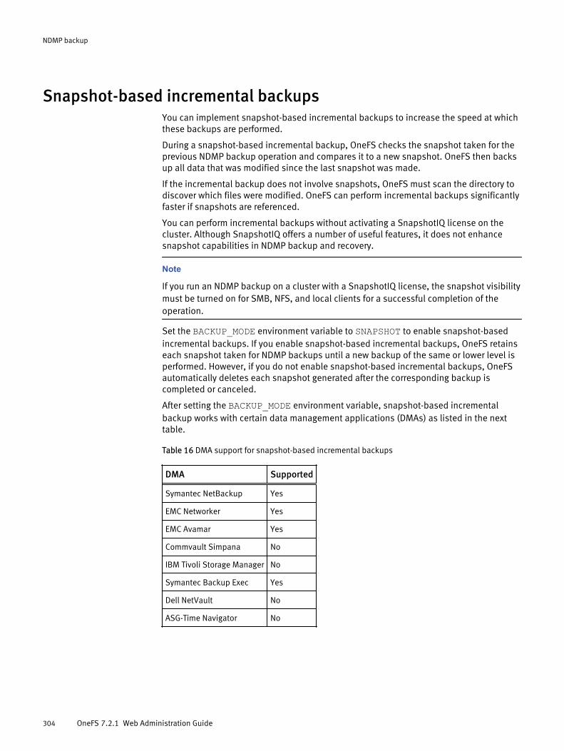
Snapshot-based incremental backupsYou can implement snapshot-based incremental backups to increase the speed at whichthese backups are performed.
During a snapshot-based incremental backup, OneFS checks the snapshot taken for theprevious NDMP backup operation and compares it to a new snapshot. OneFS then backsup all data that was modified since the last snapshot was made.
If the incremental backup does not involve snapshots, OneFS must scan the directory todiscover which files were modified. OneFS can perform incremental backups significantlyfaster if snapshots are referenced.
You can perform incremental backups without activating a SnapshotIQ license on thecluster. Although SnapshotIQ offers a number of useful features, it does not enhancesnapshot capabilities in NDMP backup and recovery.
Note
If you run an NDMP backup on a cluster with a SnapshotIQ license, the snapshot visibilitymust be turned on for SMB, NFS, and local clients for a successful completion of theoperation.
Set the BACKUP_MODE environment variable to SNAPSHOT to enable snapshot-basedincremental backups. If you enable snapshot-based incremental backups, OneFS retainseach snapshot taken for NDMP backups until a new backup of the same or lower level isperformed. However, if you do not enable snapshot-based incremental backups, OneFSautomatically deletes each snapshot generated after the corresponding backup iscompleted or canceled.
After setting the BACKUP_MODE environment variable, snapshot-based incrementalbackup works with certain data management applications (DMAs) as listed in the nexttable.
Table 16 DMA support for snapshot-based incremental backups
DMA Supported
Symantec NetBackup Yes
EMC Networker Yes
EMC Avamar Yes
Commvault Simpana No
IBM Tivoli Storage Manager No
Symantec Backup Exec Yes
Dell NetVault No
ASG-Time Navigator No
NDMP backup
304 OneFS 7.2.1 Web Administration Guide
NDMP protocol supportYou can back up cluster data through version 3 or 4 of the NDMP protocol.
OneFS supports the following features of NDMP versions 3 and 4:
l Full (level 0) NDMP backups
l Incremental (levels 1-10) NDMP backups
Note
In a level 10 NDMP backup, only data changed since the most recent incremental(level 1-9) backup or the last level 10 backup is copied. By repeating level 10backups, you can be assured that the latest versions of files in your data set arebacked up without having to run a full backup.
l Token-based NDMP backups
l NDMP TAR backup type
l Path-based and dir/node file history format
l Direct Access Restore (DAR)
l Directory DAR (DDAR)
l Including and excluding specific files and directories from backup
l Backup of file attributes
l Backup of Access Control Lists (ACLs)
l Backup of Alternate Data Streams (ADSs)
l Backup Restartable Extension (BRE)
OneFS supports connecting to clusters through IPv4 or IPv6.
Supported DMAsNDMP backups are coordinated by a data management application (DMA) that runs on abackup server.
OneFS supports all the DMAs that are listed in the Isilon Third-Party Software andHardware Compatibility Guide.
Note
All supported DMAs can connect to an EMC Isilon cluster through the IPv4 protocol.However, only some of the DMAs support the IPv6 protocol for connecting to an EMCIsilon cluster.
NDMP hardware supportOneFS can back up data to and recover data from tape devices and virtual tape libraries(VTLs).
Supported tape devices
See the OneFS and NDMP hardware compatibility section in the Isilon Third-PartySoftware and Hardware Compatibility Guide for a list of supported tape devices for
NDMP backup
NDMP protocol support 305
two-way NDMP backups. For NDMP three-way backups, the data managementapplication (DMA) determines the tape devices that are supported.
Supported tape libraries
For both the two-way and three-way NDMP backups, OneFS supports all of the tapelibraries that are supported by the DMA.
Supported virtual tape libraries
See the OneFS and NDMP hardware compatibility section in the Isilon Third-PartySoftware and Hardware Compatibility Guide for a list of supported virtual tapelibraries. For three-way NDMP backups, the DMA determines the virtual tape librariesthat will be supported.
NDMP backup limitationsNDMP backups have the following limitations.
l Does not support more than 4 KB path length.
l Does not back up file system configuration data, such as file protection level policiesand quotas.
l Does not back up tape blocks larger than 256 KB.
l Does not support recovering data from a file system other than OneFS. However, youcan migrate data through the NDMP protocol from a NetApp or EMC VNX storagesystem to OneFS through the isi_vol_copy tools. For more information on these tools,see the OneFS Migration Tools Guide.
l Backup accelerator nodes cannot interact with more than 4096 tape paths.
NDMP performance recommendationsConsider the following recommendations to optimize OneFS NDMP backups.
General performance recommendations
l Install the latest patches for OneFS and your data management application (DMA).
l Run a maximum of eight NDMP concurrent sessions per A100 Backup Acceleratornode and four NDMP concurrent sessions per Isilon IQ Backup Accelerator node toobtain optimal throughput per session.
l NDMP backups result in very high Recovery Point Objectives (RPOs) and RecoveryTime Objectives (RTOs). You can reduce your RPO and RTO by attaching one or moreBackup Accelerator nodes to the cluster and then running two-way NDMP backups.
l The throughput for an Isilon cluster during the backup and recovery operations isdependent on the dataset and is considerably reduced for small files.
l If you are backing up large numbers of small files, set up a separate schedule foreach directory.
l If you are performing NDMP three-way backups, run multiple NDMP sessions onmultiple nodes in your Isilon cluster.
l Recover files through Direct Access Restore (DAR), especially if you recover filesfrequently. However, it is recommended that you do not use DAR to recover a fullbackup or a large number of files, as DAR is better suited to restoring smallernumbers of files.
l Recover files through Directory DAR (DDAR) if you recover large numbers of filesfrequently.
NDMP backup
306 OneFS 7.2.1 Web Administration Guide
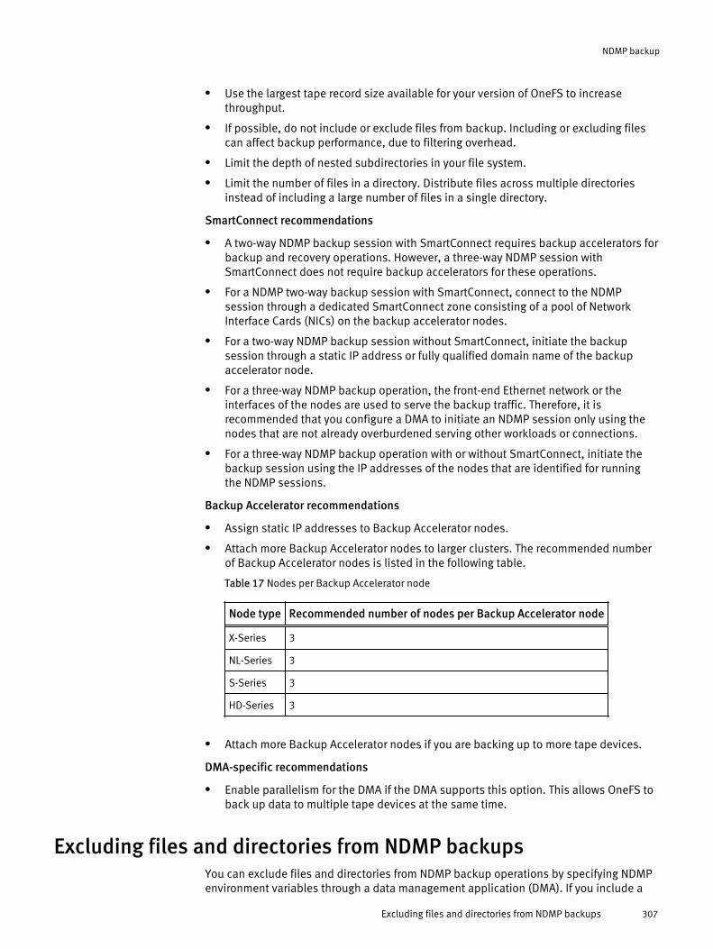
l Use the largest tape record size available for your version of OneFS to increasethroughput.
l If possible, do not include or exclude files from backup. Including or excluding filescan affect backup performance, due to filtering overhead.
l Limit the depth of nested subdirectories in your file system.
l Limit the number of files in a directory. Distribute files across multiple directoriesinstead of including a large number of files in a single directory.
SmartConnect recommendations
l A two-way NDMP backup session with SmartConnect requires backup accelerators forbackup and recovery operations. However, a three-way NDMP session withSmartConnect does not require backup accelerators for these operations.
l For a NDMP two-way backup session with SmartConnect, connect to the NDMPsession through a dedicated SmartConnect zone consisting of a pool of NetworkInterface Cards (NICs) on the backup accelerator nodes.
l For a two-way NDMP backup session without SmartConnect, initiate the backupsession through a static IP address or fully qualified domain name of the backupaccelerator node.
l For a three-way NDMP backup operation, the front-end Ethernet network or theinterfaces of the nodes are used to serve the backup traffic. Therefore, it isrecommended that you configure a DMA to initiate an NDMP session only using thenodes that are not already overburdened serving other workloads or connections.
l For a three-way NDMP backup operation with or without SmartConnect, initiate thebackup session using the IP addresses of the nodes that are identified for runningthe NDMP sessions.
Backup Accelerator recommendations
l Assign static IP addresses to Backup Accelerator nodes.
l Attach more Backup Accelerator nodes to larger clusters. The recommended numberof Backup Accelerator nodes is listed in the following table.
Table 17 Nodes per Backup Accelerator node
Node type Recommended number of nodes per Backup Accelerator node
X-Series 3
NL-Series 3
S-Series 3
HD-Series 3
l Attach more Backup Accelerator nodes if you are backing up to more tape devices.
DMA-specific recommendations
l Enable parallelism for the DMA if the DMA supports this option. This allows OneFS toback up data to multiple tape devices at the same time.
Excluding files and directories from NDMP backupsYou can exclude files and directories from NDMP backup operations by specifying NDMPenvironment variables through a data management application (DMA). If you include a
NDMP backup
Excluding files and directories from NDMP backups 307
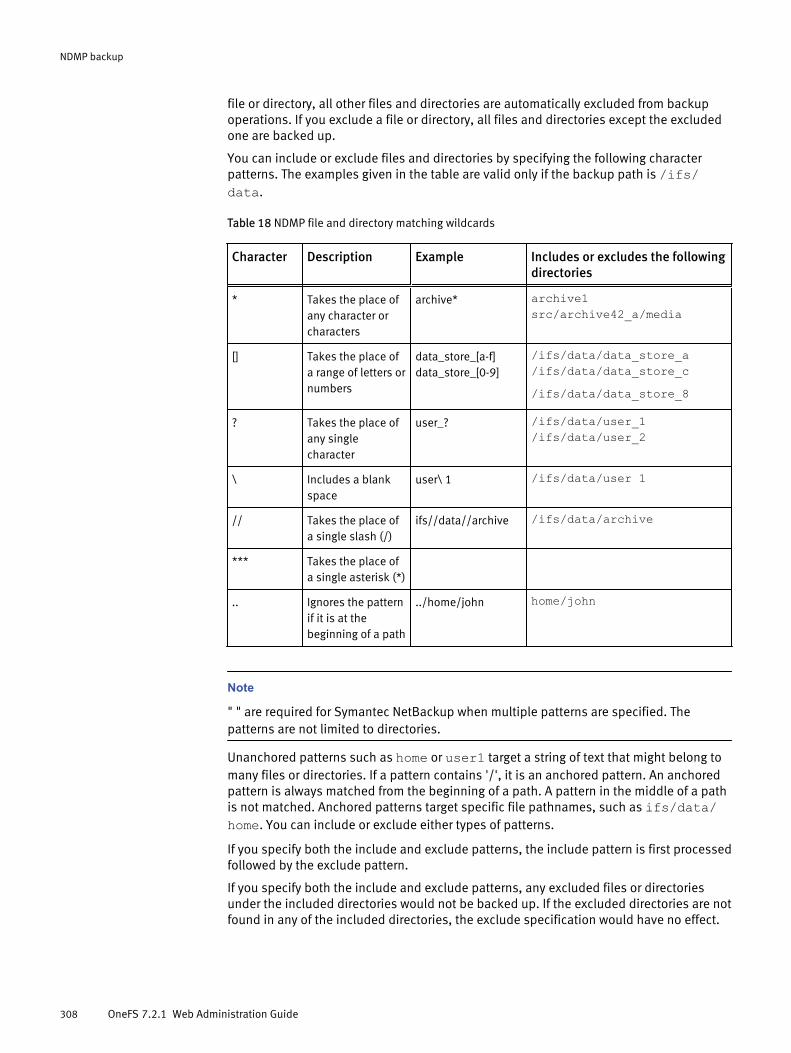
file or directory, all other files and directories are automatically excluded from backupoperations. If you exclude a file or directory, all files and directories except the excludedone are backed up.
You can include or exclude files and directories by specifying the following characterpatterns. The examples given in the table are valid only if the backup path is /ifs/data.
Table 18 NDMP file and directory matching wildcards
Character Description Example Includes or excludes the followingdirectories
* Takes the place ofany character orcharacters
archive* archive1src/archive42_a/media
[] Takes the place ofa range of letters ornumbers
data_store_[a-f]data_store_[0-9]
/ifs/data/data_store_a/ifs/data/data_store_c/ifs/data/data_store_8
? Takes the place ofany singlecharacter
user_? /ifs/data/user_1/ifs/data/user_2
\ Includes a blankspace
user\ 1 /ifs/data/user 1
// Takes the place ofa single slash (/)
ifs//data//archive /ifs/data/archive
*** Takes the place ofa single asterisk (*)
.. Ignores the patternif it is at thebeginning of a path
../home/john home/john
Note
" " are required for Symantec NetBackup when multiple patterns are specified. Thepatterns are not limited to directories.
Unanchored patterns such as home or user1 target a string of text that might belong tomany files or directories. If a pattern contains '/', it is an anchored pattern. An anchoredpattern is always matched from the beginning of a path. A pattern in the middle of a pathis not matched. Anchored patterns target specific file pathnames, such as ifs/data/home. You can include or exclude either types of patterns.
If you specify both the include and exclude patterns, the include pattern is first processedfollowed by the exclude pattern.
If you specify both the include and exclude patterns, any excluded files or directoriesunder the included directories would not be backed up. If the excluded directories are notfound in any of the included directories, the exclude specification would have no effect.
NDMP backup
308 OneFS 7.2.1 Web Administration Guide

Note
Specifying unanchored patterns can degrade the performance of backups. It isrecommended that you avoid unanchored patterns whenever possible.
Configuring basic NDMP backup settingsYou can configure NDMP backup settings to control how these backups are performed forthe cluster. You can also configure OneFS to interact with a specific data managementapplication (DMA) for NDMP backups.
Configure and enable NDMP backupOneFS prevents NDMP backups by default. Before you can perform NDMP backups, youmust enable NDMP backups and configure NDMP settings.
Procedure
1. Click Data Protection > Backup > NDMP Settings.
2. In the Service area, click Enable.
3. (Optional) To specify a port through which data management applications (DMAs)access the cluster, or the DMA vendor that OneFS is to interact with, in the Settingsarea, click Edit settings.
l In the Port number field, type a port number.
l From the DMA vendor list, select the name of the DMA vendor to manage backupoperations.
If your DMA vendor is not included in the list, select generic. However, note thatany vendors not included on the list are not officially supported and might notfunction as expected.
4. Add an NDMP user account through which your DMA can access the cluster.
Disable NDMP backupYou can disable NDMP backup if you no longer want to use this backup method.
Procedure
1. Click Data Protection > Backup > NDMP Settings.
2. In the Service area, click Disable.
View NDMP backup settingsYou can view current NDMP backup settings. These settings define whether NDMPbackup is enabled, the port through which your data management application (DMA)connects to the cluster, and the DMA vendor that OneFS is configured to interact with.
Procedure
1. Click Data Protection > Backup > NDMP Settings and view NDMP backup settings.
2. In the Settings area, review NDMP backup settings.
NDMP backup
Configuring basic NDMP backup settings 309
NDMP backup settingsYou can configure the following settings to control how NDMP backups are performed onthe cluster.
Port number
The number of the port through which the data management application (DMA) canconnect to the cluster.
DMA vendor
The DMA vendor that the cluster is configured to interact with.
Managing NDMP user accountsYou can create, delete, and modify the passwords of NDMP user accounts.
Create an NDMP user accountBefore you can perform NDMP backups, you must create an NDMP user account throughwhich your data management application (DMA) can access the Isilon cluster.
Procedure
1. Click Data Protection > Backup > NDMP Settings.
2. In the NDMP Administrators area, click Add administrator.
3. In the Add Administrator dialog box, in the Name field, type a name for the account.
4. In the Password and Confirm password fields, type a password for the account.
5. Click Submit.
Modify the password of an NDMP user accountYou can modify the password for an NDMP user account.
Procedure
1. Click Data Protection > Backup > NDMP Settings.
2. In the NDMP Administrator table, in the row for an NDMP user account, click Changepassword.
3. In the Password and Confirm password fields, type a new password for the account.
4. Click Submit.
Delete an NDMP user accountYou can delete an NDMP user account.
Procedure
1. Click Data Protection > Backup > NDMP Settings.
2. In the NDMP Administrators table, in the row for an NDMP user account, click Delete.
3. In the Confirm dialog box, click Yes.
NDMP backup
310 OneFS 7.2.1 Web Administration Guide
View NDMP user accountsYou can view information about NDMP user accounts.
Procedure
1. Click Data Protection > Backup > NDMP Settings.
2. In the NDMP administrators area, review information about NDMP user accounts.
Managing NDMP backup devicesAfter you attach a tape or media changer device to a Backup Accelerator node, you mustconfigure OneFS to detect and establish a connection to the device. After the connectionbetween the cluster and the backup device is established, you can modify the name thatthe cluster has assigned to the device, or disconnect the device from the cluster.
Detect NDMP backup devicesIf you connect a tape device or media changer to a Backup Accelerator node, you mustconfigure OneFS to detect the device. Only then can OneFS back up data to and restoredata from the device. In OneFS, you can scan a specific node, a specific port, or all portson all nodes.
Procedure
1. Click Data Protection > Backup > Devices.
2. Click Discover devices.
3. (Optional) To scan only a specific node for NDMP devices, from the Nodes list, select anode.
4. (Optional) To scan only a specific port for NDMP devices, from the Ports list, select aport.
If you specify a port and a node, only the specified port on the node is scanned.However, if you specify only a port, the specified port will be scanned on all nodes.
5. (Optional) To remove entries for devices or paths that have become inaccessible,select the Delete inaccessible paths or devices check box.
6. Click Submit.
Results
For each device that is detected, an entry is added to either the Tape Devices or MediaChangers tables.
Modify the name of an NDMP backup deviceYou can modify the name of an NDMP backup device in OneFS.
Procedure
1. Click Data Protection > Backup > Devices.
2. In the Tape Devices table, click the name of a backup device entry.
3. In the Rename Device dialog box, in the Device Name field, type a new name for thebackup device.
4. Click Submit.
NDMP backup
View NDMP user accounts 311
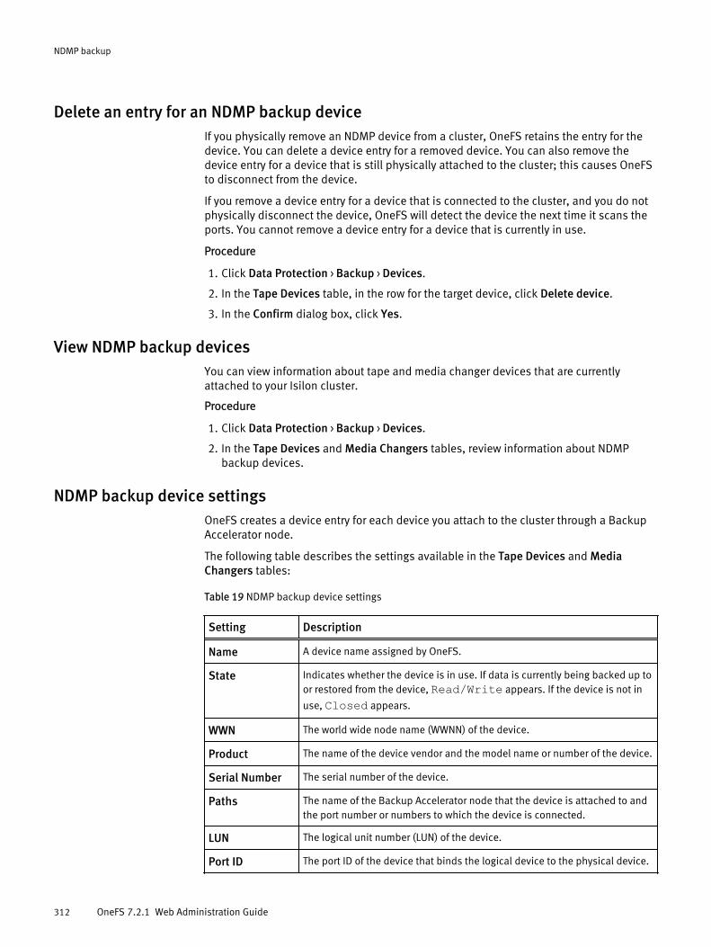
Delete an entry for an NDMP backup deviceIf you physically remove an NDMP device from a cluster, OneFS retains the entry for thedevice. You can delete a device entry for a removed device. You can also remove thedevice entry for a device that is still physically attached to the cluster; this causes OneFSto disconnect from the device.
If you remove a device entry for a device that is connected to the cluster, and you do notphysically disconnect the device, OneFS will detect the device the next time it scans theports. You cannot remove a device entry for a device that is currently in use.
Procedure
1. Click Data Protection > Backup > Devices.
2. In the Tape Devices table, in the row for the target device, click Delete device.
3. In the Confirm dialog box, click Yes.
View NDMP backup devicesYou can view information about tape and media changer devices that are currentlyattached to your Isilon cluster.
Procedure
1. Click Data Protection > Backup > Devices.
2. In the Tape Devices and Media Changers tables, review information about NDMPbackup devices.
NDMP backup device settingsOneFS creates a device entry for each device you attach to the cluster through a BackupAccelerator node.
The following table describes the settings available in the Tape Devices and MediaChangers tables:
Table 19 NDMP backup device settings
Setting Description
Name A device name assigned by OneFS.
State Indicates whether the device is in use. If data is currently being backed up toor restored from the device, Read/Write appears. If the device is not in
use, Closed appears.
WWN The world wide node name (WWNN) of the device.
Product The name of the device vendor and the model name or number of the device.
Serial Number The serial number of the device.
Paths The name of the Backup Accelerator node that the device is attached to andthe port number or numbers to which the device is connected.
LUN The logical unit number (LUN) of the device.
Port ID The port ID of the device that binds the logical device to the physical device.
NDMP backup
312 OneFS 7.2.1 Web Administration Guide

Table 19 NDMP backup device settings (continued)
Setting Description
WWPN The world wide port name (WWPN) of the port on the tape or media changerdevice.
Managing NDMP backup portsYou can manage the Fibre Channel ports that connect tape and media changer devices toa Backup Accelerator node. You can also enable, disable, or modify the settings of anNDMP backup port.
Modify NDMP backup port settingsYou can modify the settings of an NDMP backup port.
Procedure
1. Click Data Protection > Backup > Ports.
2. In the Sessions table, click the name of a port.
3. In the Edit Port dialog box, modify port settings as needed, and then click Submit.
Enable or disable an NDMP backup portYou can enable or disable an NDMP backup port.
Procedure
1. Click Data Protection > Backup > Ports.
2. In the Ports table, in the row of a port, click Enable or Disable.
View NDMP backup portsYou can view information about Fibre Channel ports of Backup Accelerator nodesattached to a cluster.
Procedure
1. Click Data Protection > Backup > Ports.
2. In the Ports table, review information about NDMP backup ports.
NDMP backup port settingsOneFS assigns default settings to each port on each Backup Accelerator node attached tothe cluster. These settings identify each port and specify how the port interacts withNDMP backup devices.
The settings that appear in the Ports table are as follows:
Table 20 NDMP backup port settings
Setting Description
Port The name of the Backup Accelerator node, and the number of the port.
NDMP backup
Managing NDMP backup ports 313
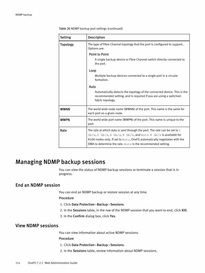
Table 20 NDMP backup port settings (continued)
Setting Description
Topology The type of Fibre Channel topology that the port is configured to support..Options are:
Point to Point
A single backup device or Fibre Channel switch directly connected tothe port.
Loop
Multiple backup devices connected to a single port in a circularformation.
Auto
Automatically detects the topology of the connected device. This is therecommended setting, and is required if you are using a switched-fabric topology.
WWNN The world wide node name (WWNN) of the port. This name is the same foreach port on a given node.
WWPN The world wide port name (WWPN) of the port. This name is unique to theport.
Rate The rate at which data is sent through the port. The rate can be set to 1Gb/s, 2 Gb/s, 4 Gb/s, 8 Gb/s, and Auto. 8 Gb/s is available for
A100 nodes only. If set to Auto, OneFS automatically negotiates with the
DMA to determine the rate. Auto is the recommended setting.
Managing NDMP backup sessionsYou can view the status of NDMP backup sessions or terminate a session that is inprogress.
End an NDMP sessionYou can end an NDMP backup or restore session at any time.
Procedure
1. Click Data Protection > Backup > Sessions.
2. In the Sessions table, in the row of the NDMP session that you want to end, click Kill.
3. In the Confirm dialog box, click Yes.
View NDMP sessionsYou can view information about active NDMP sessions.
Procedure
1. Click Data Protection > Backup > Sessions.
2. In the Sessions table, review information about NDMP sessions.
NDMP backup
314 OneFS 7.2.1 Web Administration Guide
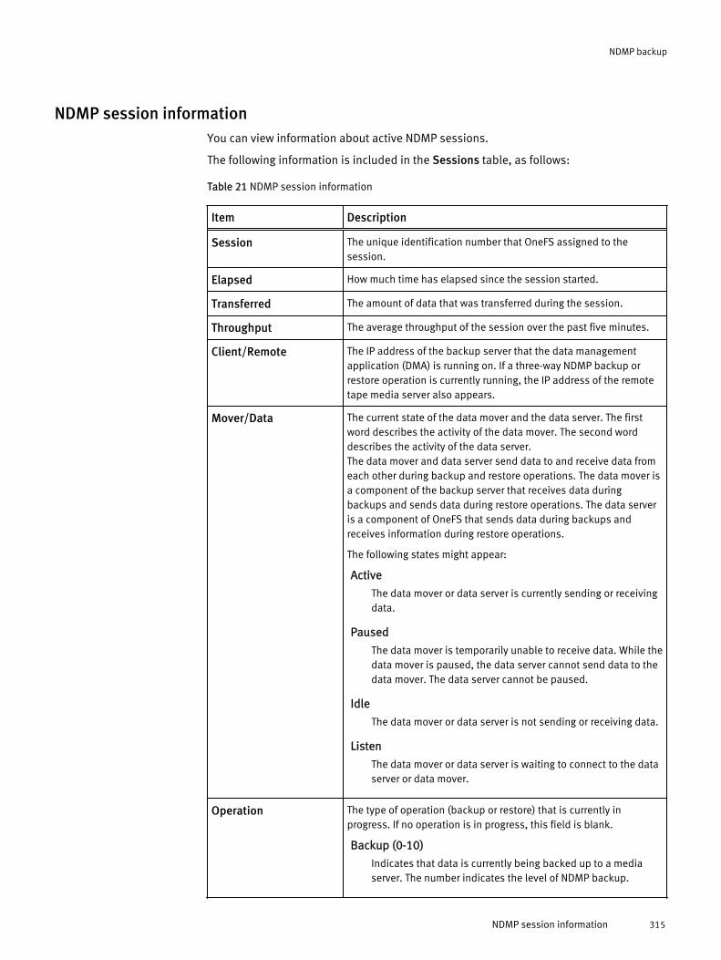
NDMP session informationYou can view information about active NDMP sessions.
The following information is included in the Sessions table, as follows:
Table 21 NDMP session information
Item Description
Session The unique identification number that OneFS assigned to thesession.
Elapsed How much time has elapsed since the session started.
Transferred The amount of data that was transferred during the session.
Throughput The average throughput of the session over the past five minutes.
Client/Remote The IP address of the backup server that the data managementapplication (DMA) is running on. If a three-way NDMP backup orrestore operation is currently running, the IP address of the remotetape media server also appears.
Mover/Data The current state of the data mover and the data server. The firstword describes the activity of the data mover. The second worddescribes the activity of the data server.The data mover and data server send data to and receive data fromeach other during backup and restore operations. The data mover isa component of the backup server that receives data duringbackups and sends data during restore operations. The data serveris a component of OneFS that sends data during backups andreceives information during restore operations.
The following states might appear:
Active
The data mover or data server is currently sending or receivingdata.
Paused
The data mover is temporarily unable to receive data. While thedata mover is paused, the data server cannot send data to thedata mover. The data server cannot be paused.
Idle
The data mover or data server is not sending or receiving data.
Listen
The data mover or data server is waiting to connect to the dataserver or data mover.
Operation The type of operation (backup or restore) that is currently inprogress. If no operation is in progress, this field is blank.
Backup (0-10)
Indicates that data is currently being backed up to a mediaserver. The number indicates the level of NDMP backup.
NDMP backup
NDMP session information 315
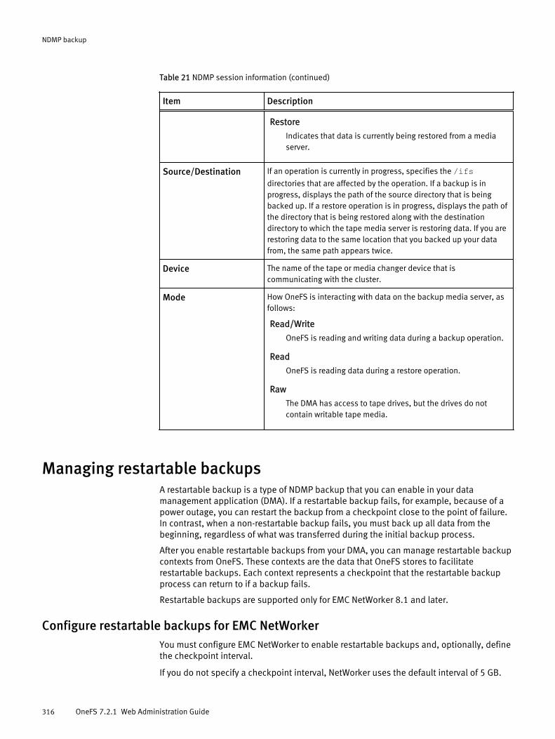
Table 21 NDMP session information (continued)
Item Description
Restore
Indicates that data is currently being restored from a mediaserver.
Source/Destination If an operation is currently in progress, specifies the /ifsdirectories that are affected by the operation. If a backup is inprogress, displays the path of the source directory that is beingbacked up. If a restore operation is in progress, displays the path ofthe directory that is being restored along with the destinationdirectory to which the tape media server is restoring data. If you arerestoring data to the same location that you backed up your datafrom, the same path appears twice.
Device The name of the tape or media changer device that iscommunicating with the cluster.
Mode How OneFS is interacting with data on the backup media server, asfollows:
Read/Write
OneFS is reading and writing data during a backup operation.
Read
OneFS is reading data during a restore operation.
Raw
The DMA has access to tape drives, but the drives do notcontain writable tape media.
Managing restartable backupsA restartable backup is a type of NDMP backup that you can enable in your datamanagement application (DMA). If a restartable backup fails, for example, because of apower outage, you can restart the backup from a checkpoint close to the point of failure.In contrast, when a non-restartable backup fails, you must back up all data from thebeginning, regardless of what was transferred during the initial backup process.
After you enable restartable backups from your DMA, you can manage restartable backupcontexts from OneFS. These contexts are the data that OneFS stores to facilitaterestartable backups. Each context represents a checkpoint that the restartable backupprocess can return to if a backup fails.
Restartable backups are supported only for EMC NetWorker 8.1 and later.
Configure restartable backups for EMC NetWorkerYou must configure EMC NetWorker to enable restartable backups and, optionally, definethe checkpoint interval.
If you do not specify a checkpoint interval, NetWorker uses the default interval of 5 GB.
NDMP backup
316 OneFS 7.2.1 Web Administration Guide
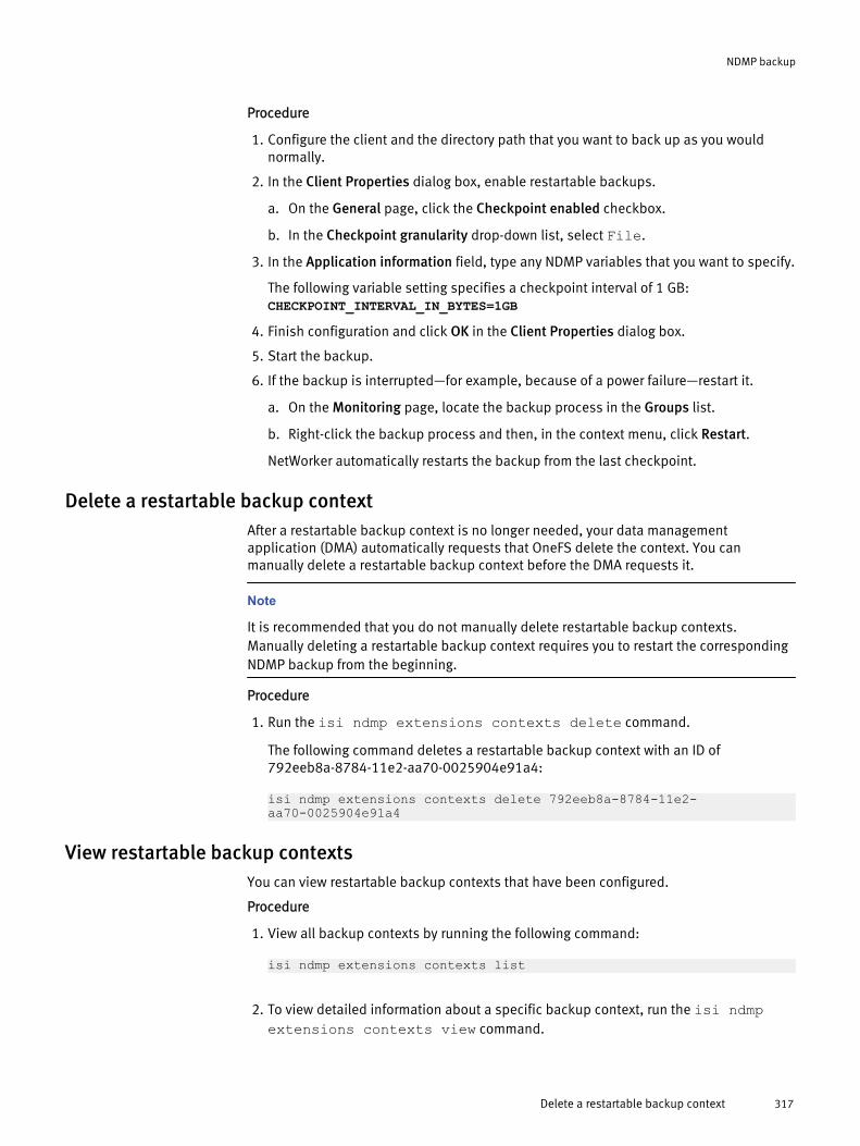
Procedure
1. Configure the client and the directory path that you want to back up as you wouldnormally.
2. In the Client Properties dialog box, enable restartable backups.
a. On the General page, click the Checkpoint enabled checkbox.
b. In the Checkpoint granularity drop-down list, select File.
3. In the Application information field, type any NDMP variables that you want to specify.
The following variable setting specifies a checkpoint interval of 1 GB:CHECKPOINT_INTERVAL_IN_BYTES=1GB
4. Finish configuration and click OK in the Client Properties dialog box.
5. Start the backup.
6. If the backup is interrupted—for example, because of a power failure—restart it.
a. On the Monitoring page, locate the backup process in the Groups list.
b. Right-click the backup process and then, in the context menu, click Restart.
NetWorker automatically restarts the backup from the last checkpoint.
Delete a restartable backup contextAfter a restartable backup context is no longer needed, your data managementapplication (DMA) automatically requests that OneFS delete the context. You canmanually delete a restartable backup context before the DMA requests it.
Note
It is recommended that you do not manually delete restartable backup contexts.Manually deleting a restartable backup context requires you to restart the correspondingNDMP backup from the beginning.
Procedure
1. Run the isi ndmp extensions contexts delete command.
The following command deletes a restartable backup context with an ID of792eeb8a-8784-11e2-aa70-0025904e91a4:
isi ndmp extensions contexts delete 792eeb8a-8784-11e2-aa70-0025904e91a4
View restartable backup contextsYou can view restartable backup contexts that have been configured.
Procedure
1. View all backup contexts by running the following command:
isi ndmp extensions contexts list
2. To view detailed information about a specific backup context, run the isi ndmpextensions contexts view command.
NDMP backup
Delete a restartable backup context 317
The following command displays detailed information about a backup context with anID of 792eeb8a-8784-11e2-aa70-0025904e91a4:
isi ndmp extensions contexts view 792eeb8a-8784-11e2-aa70-0025904e91a4
Configure restartable backup settingsYou can specify the number of restartable backup contexts that OneFS retains at a time,up to a maximum of 1024 contexts.
Procedure
1. Run the isi ndmp extensions settings modify command.
The following command sets the maximum number of restartable backup contexts to128:
isi ndmp extensions settings modify --bre_max_contexts 128
View restartable backup settingsYou can view the current limit of restartable backup contexts that OneFS retains at onetime.
Procedure
1. Run the following command:
isi ndmp extensions settings view
Managing file list backupsIf your data management application (DMA) can pass environment variables to OneFS,you can control backups by specifying a file list.
Currently, EMC Networker and Symantec NetBackup can pass environment variables toOneFS.
With a normal NDMP level 0 (full) backup, your DMA backs up an entire source directory.With an NDMP incremental (level 1-10) backup, your DMA backs up only those files thathave been created or changed since the previous incremental backup of the same level.
When you specify a file list backup, only the listed files and subdirectories in the sourcedirectory are backed up. With a level 0 file list backup, all listed files and directories inthe source directory are backed up.
A backup level other than 0 triggers an incremental file list backup. In an incremental filelist backup, only the listed files that were created or changed in the source directory sincethe last incremental backup of the same level are backed up.
To configure a file list backup, you must complete the following tasks:
l Create the file list and place it in OneFS
l Specify the path of the source directory
l Specify the file list location
The file list is an ASCII text file that lists the pathnames of files to be backed up. Thepathnames must be relative to the path specified in the FILESYSTEM environmentvariable. Absolute file paths in the file list are not supported. The pathnames of all files
NDMP backup
318 OneFS 7.2.1 Web Administration Guide

must be included, or they are not backed up. For example, if you include the pathname ofa subdirectory, only the subdirectory, not the files it contains, is backed up.
To specify the full path of the source directory to be backed up, you must specify theFILESYSTEM environment variable in your DMA. For example:
FILESYSTEM=/ifs/data/projects
To specify the pathname of the file list, you must specify the environment variable,BACKUP_FILE_LIST in your DMA. The file list must be accessible from the nodeperforming the backup. For example:
BACKUP_FILE_LIST=/ifs/data/proj_list.txt
Format of a backup file listYou must create a file list to enable a file list backup.
A file list backup requires an ASCII text file in a particular format to identify thepathnames of files to be backed up. Following is an example of a file list with pathnamesrelative to /ifs/data/projects:
project-summary_rev0.xlsproject-summary_rev3.xlsproj001/plan/plan001.docproj001/plan/plan001.pdfproj001/plan/proj-logo.pngproj001/plan/schedule001.xlsproj001/plan/stakeholders_list.txtproj001/plan/team_pic.pngproj002/plan/logo.pngproj002/plan/projplan002.docproj002/plan/projplan002.pdfproj002/plan/sched-002.xlsproj002/plan/stakeholders.txtproj002/plan/team.pngproj005/plan/projectlogo.pngproj005/plan/projectteam.pngproj005/plan/proj-plan005.docproj005/plan/proj-plan005.pdfproj005/plan/schedule.xlsproj005/plan/stakeholders.txt
As shown in the example, the pathnames are relative to the full path of the sourcedirectory, which you specify in the FILESYSTEM environment variable. Absolute file pathsare not supported in the file list.
Also as shown, the directories and files must be in sorted order for the backup to besuccessful.
The pathnames of all files must be included in the file list, or they are not backed up. Forexample, if you only include the pathname of a subdirectory, the subdirectory is backedup, but not the files the subdirectory contains. The exception is ADS (alternate datastreams). All ADS associated with a file to be backed up are automatically backed up.
Placement of the file listBefore you can perform a file list backup, you must place the file list in OneFS.
For example, suppose the FILESYSTEM environment variable specifies the full path of thedirectory to be backed up as /ifs/data/projects. You can place the text filecontaining the file list anywhere within the /ifs path.
NDMP backup
Format of a backup file list 319
Start a file list backupYou can configure and start a file list backup from your data management application(DMA).
Before you begin
You should have already specified and saved the list of files to be backed up in an ASCIItext file.
Configure a file list backup from your DMA as you would any backup, but with a fewadditional steps as described in the following procedure.
Procedure
1. Copy the file list to the OneFS file system on the cluster containing the files to bebacked up.
For example, if the directory that you specify in the FILESYSTEM environmentvariable is /ifs/data/projects, you could place your file list at /ifs/data.
2. In your DMA, specify the BACKUP_FILE_LIST environment variable to be the fullpathname of the file list.
For example, if the file list was named proj_backup.txt, and you placed itat /ifs/data, specify /ifs/data/proj_backup.txt as the full pathname ofthe file list.
3. Start your backup as you normally would.
Results
The files in your file list are backed up as specified.
NDMP restore operationsNDMP supports the following types of restore operations:
l Parallel restore (multi-threaded process)
l Serial restore (single-threaded process)
Parallel restore operationIn OneFS, the default NDMP restore for any path is the parallel restore operation. Parallel(multi-threaded) restore enables faster full or partial restore operations by writing data tothe cluster as fast as the data can be read from the tape. However, if you specify DAR(direct access restore), the operation reverts to serial processing.
NDMP serial restore operationFor troubleshooting or for other purposes, you can run a serial restore operation whichuses fewer system resources. The serial restore operation runs as a single-threadedprocess and restores one file at a time to the specified path.
NDMP backup
320 OneFS 7.2.1 Web Administration Guide

Specify a serial restore operationYou can use the RESTORE_OPTIONS environment variable to specify a serial (single-threaded) restore operation.
Procedure
1. In your data management application, configure a restore operation as you normallywould.
2. Make sure that the RESTORE_OPTIONS environment variable is set to 1 on your datamanagement application.
If the RESTORE_OPTIONS environment variable is not already set to 1, specify theisi ndmp settings variables modify command from the OneFS commandline. The following command specifies serial restore for the /ifs/data/projectsdirectory:
isi ndmp settings variables modify --path /ifs/data/projects --name restore_options --value 1
The value of the path option is the FILESYSTEM environment variable set during thebackup operation. The value that you specify for the name option is case sensitive.
3. Start the restore operation.
Sharing tape drives between clustersMultiple Isilon clusters, or an Isilon cluster and a third-party NAS system, can beconfigured to share a single tape drive. This helps to maximize the use of the tapeinfrastructure in your data center.
In your data management application (DMA), you must configure NDMP to control thetape drive and ensure that it is shared properly. The following configurations aresupported.
OneFS Versions Supported DMAs Tested configurations
l 7.1.1
l 7.1.0.1 (andlater)*
l 7.0.2.5
l 6.6.5.26
l EMC NetWorker 8.0 and later
l Symantec NetBackup 7.5and later
l Isilon Backup Accelerator with asecond Backup Accelerator
l Isilon Backup Accelerator with aNetApp storage system
* The tape drive sharing function is not supported in the OneFS 7.0.1 release.
EMC NetWorker refers to the tape drive sharing capability as DDS (dynamic drive sharing).Symantec NetBackup uses the term SSO (shared storage option). Consult your DMAvendor documentation for configuration instructions.
Managing default NDMP settingsIn OneFS, you can manage NDMP backup and restore operations by specifying defaultNDMP environment variables. You can also override default NDMP environment variables
NDMP backup
Specify a serial restore operation 321
through your data management application (DMA). For more information about specifyingNDMP environment variables through your DMA, see your DMA documentation.
Set default NDMP settings for a directoryYou can set default NDMP settings for a directory.
Procedure
1. Open a secure shell (SSH) connection to any node in the cluster and log in.
2. Set default NDMP settings by running the isi ndmp settings variablescreate command.
For example, the following command enables snapshot-based incremental backupsfor /ifs/data/media:
isi ndmp settings variables create /ifs/data/media BACKUP_MODE SNAPSHOT
Modify default NDMP settings for a directoryYou can modify the default NDMP settings for a directory.
Procedure
1. Open a secure shell (SSH) connection to any node in the cluster and log in.
2. Modify default NDMP settings by running the isi ndmp settings variablesmodify command.
For example, the following command sets the default file history format to path-basedformat for /ifs/data/media:
isi ndmp settings variables modify /ifs/data/media HIST F3. (Optional) To remove a default NDMP setting for a directory, run the isi ndmpsettings variables delete command:
For example, the following command removes the default file history formatfor /ifs/data/media:
isi ndmp settings variables delete /ifs/data/media --name HIST
View default NDMP settings for directoriesYou can view the default NDMP settings for directories.
Procedure
1. Open a secure shell (SSH) connection to any node in the cluster and log in.
2. View default NDMP settings by running the following command:
isi ndmp settings variables list
NDMP backup
322 OneFS 7.2.1 Web Administration Guide

NDMP environment variablesYou can specify default settings of NDMP backup and restore operations through NDMPenvironment variables. You can also specify NDMP environment variables through yourdata management application (DMA).
Table 22 NDMP environment variables
Environment variable Validvalues
Default Description
BACKUP_MODE= TIMESTAMPSNAPSHOT
TIMESTAMP Enables or disablessnapshot-basedincremental backups. Toenable snapshot-basedincremental backups,specify SNAPSHOT. To
disable snapshot-basedincremental backups,specify TIMESTAMP.
FILESYSTEM= <file-path> None Specifies the full path ofthe directory you want toback up. Must be specifiedby the DMA before startingthe backup, or an error isgenerated.
LEVEL= <integer> 0 Specifies the level ofNDMP backup to perform.The following values arevalid:
0Performs a full NDMPbackup.
1 - 9Performs anincremental backupat the specified level.
10Performs unlimitedincremental backups.
UPDATE= YN
Y Determines whetherOneFS updates the dumpdates file.
YOneFS updates thedump dates file.
NDMP backup
NDMP environment variables 323

Table 22 NDMP environment variables (continued)
Environment variable Validvalues
Default Description
NOneFS does notupdate the dumpdates file.
HIST= <file-history-format>
Y Specifies the file historyformat.The following values arevalid:
DSpecifies dir/nodefile history.
FSpecifies path-basedfile history.
YSpecifies the defaultfile history formatdetermined by yourNDMP backupsettings.
NDisables file history.
DIRECT= YN
N Enables or disables DirectAccess Restore (DAR) andDirectory DAR (DDAR). Thefollowing values are valid:
YEnables DAR andDDAR.
NDisables DAR andDDAR.
FILES= <file-matching-pattern>
None If you specify this option,OneFS backs up only filesand directories that meetthe specified pattern.Separate multiple patternswith a space.
EXCLUDE= <file-matching-pattern>
None If you specify this option,OneFS does not back upfiles and directories that
NDMP backup
324 OneFS 7.2.1 Web Administration Guide

Table 22 NDMP environment variables (continued)
Environment variable Validvalues
Default Description
meet the specified pattern.Separate multiple patternswith a space.
RESTORE_HARDLINK_BY_TABLE=
YN
N Determines whetherOneFS recovers hard linksby building a hard-linktable during restoreoperations. Specify thisoption if hard links wereincorrectly backed up, andrestore operations arefailing.If a restore operation failsbecause hard links wereincorrectly backed up, thefollowing messageappears in the NDMPbackup logs:
Bad hardlink path for <path>
BACKUP_FILE_LIST= <file-path> None Specifies the pathname inOneFS of the file list tocontrol the backup. Thisvariable must be passedfrom the DMA initiating thebackup.Currently, only EMCNetworker and SymantecNetBackup can passenvironment variables toOneFS.
RESTORE_OPTIONS= 01
0 The restore operation, bydefault, is multi-threadedto improve performance.To change the restoreoperation to single-threaded, specifyRESTORE_OPTIONS=1
NDMP backup
NDMP environment variables 325
Managing snapshot based incremental backupsAfter you enable snapshot-based incremental backups, you can view and delete thesnapshots created for these backups.
Enable snapshot-based incremental backups for a directoryYou can configure OneFS to perform snapshot-based incremental backups for a directoryby default. You can also override the default setting in your data management application(DMA).
Procedure
1. Run the isi ndmp settings variable create command.
The following command enables snapshot-based incremental backups for /ifs/data/media:
isi ndmp settings variables create /ifs/data/media BACKUP_MODE SNAPSHOT
View snapshots for snapshot-based incremental backupsYou can view snapshots generated for snapshot-based incremental backups.
Procedure
1. Run the following command:
isi ndmp dumpdates list
Delete snapshots for snapshot-based incremental backupsYou can delete snapshots created for snapshot-based incremental backups.
Note
It is recommended that you do not delete snapshots created for snapshot-basedincremental backups. If all snapshots are deleted for a path, the next backup performedfor the path is a full backup.
Procedure
1. Run the isi ndmp dumpdates delete command.
The following command deletes all snapshots created for backing up /ifs/data/media:
isi ndmp dumpdates delete /ifs/data/media
NDMP backup
326 OneFS 7.2.1 Web Administration Guide
View NDMP backup logsYou can view information about NDMP backup and restore operations through NDMPbackup logs.
Procedure
1. Click Data Protection > Backup > Logs.
2. In the Log Location area, from the Node list, select a node.
3. In the Log Contents area, review information about NDMP backup and restoreoperations.
NDMP backup
View NDMP backup logs 327

NDMP backup
328 OneFS 7.2.1 Web Administration Guide
CHAPTER 17
File retention with SmartLock
This section contains the following topics:
l SmartLock overview............................................................................................ 330l Compliance mode............................................................................................... 330l SmartLock directories..........................................................................................330l Replication and backup with SmartLock.............................................................. 331l SmartLock license functionality...........................................................................332l SmartLock considerations................................................................................... 332l Set the compliance clock.................................................................................... 333l View the compliance clock.................................................................................. 333l Creating a SmartLock directory............................................................................ 334l Managing SmartLock directories......................................................................... 335l Managing files in SmartLock directories.............................................................. 339
File retention with SmartLock 329
SmartLock overviewWith the SmartLock software module, you can prevent users from modifying and deletingfiles on an EMC Isilon cluster. To protect data in this manner, you must activate aSmartLock license.
With SmartLock, you can identify a directory in OneFS as a WORM domain. WORM standsfor write once, read many. All files within the WORM domain will be committed to aWORM state, meaning that those files cannot be overwritten, modified, or deleted.
After a file is removed from a WORM state, you can delete the file. However, you can nevermodify a file that has been committed to a WORM state, even after it is removed from aWORM state.
In OneFS, SmartLock can be configured as one of two modes: compliance mode orenterprise mode.
Compliance modeSmartLock compliance mode enables you to protect your data in compliance with theregulations defined by U.S. Securities and Exchange Commission rule 17a-4.
Note
You can upgrade an EMC Isilon cluster to SmartLock compliance mode only during theinitial cluster configuration process, prior to activating a SmartLock license. A clustercannot be converted to SmartLock compliance mode after the cluster is initiallyconfigured and put into production.
If you upgrade a cluster to SmartLock compliance mode, the root user is removed and youare not able to log in to that cluster through the root user account. Instead, you can log into the cluster through the compliance administrator account that is configured duringinitial cluster configuration.
When you are logged in to a SmartLock compliance mode cluster through the complianceadministrator account, you can perform administrative tasks through the sudocommand.
SmartLock directoriesIn a SmartLock directory, you can commit a file to a WORM state manually or you canconfigure SmartLock to automatically commit the file. Before you can create SmartLockdirectories, you must activate a SmartLock license on the cluster.
You can create two types of SmartLock directories: enterprise and compliance. However,you can create compliance directories only if the EMC Isilon cluster has been set up inSmartLock compliance mode during initial configuration.
Enterprise directories enable you to protect your data without restricting your cluster tocomply with regulations defined by U.S. Securities and Exchange Commission rule 17a-4.If you commit a file to a WORM state in an enterprise directory, the file can never bemodified and cannot be deleted until the retention period passes.
However, if you own a file and have been assigned the ISI_PRIV_IFS_WORM_DELETEprivilege, or you are logged in through the root user account, you can delete the filethrough the privileged delete feature before the retention period passes. The privileged
File retention with SmartLock
330 OneFS 7.2.1 Web Administration Guide

delete feature is not available for compliance directories. Enterprise directories referencethe system clock to facilitate time-dependent operations, including file retention.
Compliance directories enable you to protect your data in compliance with theregulations defined by U.S. Securities and Exchange Commission rule 17a-4. If youcommit a file to a WORM state in a compliance directory, the file cannot be modified ordeleted before the specified retention period has expired. You cannot delete committedfiles, even if you are logged in to the compliance administrator account. Compliancedirectories reference the compliance clock to facilitate time-dependent operations,including file retention.
You must set the compliance clock before you can create compliance directories. You canset the compliance clock only once. After you set the compliance clock, you cannotmodify the compliance clock time. The compliance clock is controlled by the complianceclock daemon. Because root and compliance administrator users can disable thecompliance clock daemon, it is possible for those users to increase the retention periodof WORM committed files in compliance mode. However, it is not possible to decreasethe retention period of a WORM committed file.
Replication and backup with SmartLockYou must ensure that SmartLock directories remain protected during replication andbackup operations.
If you are replicating SmartLock directories with SyncIQ, it is recommended that youconfigure all nodes on the source and target clusters into Network Time Protocol (NTP)peer mode to ensure that the node clocks are synchronized. For compliance clusters, it isrecommended that you configure all nodes on the source and target clusters into NTPpeer mode before you set the compliance clock to ensure that the compliance clocks areinitially set to the same time.
Note
If you replicate data to a SmartLock directory, do not configure SmartLock settings for thatdirectory until you are no longer replicating data to the directory. Configuring anautocommit time period for a SmartLock directory that you are replicating to can causereplication jobs to fail. If the target directory commits a file to a WORM state, and the fileis modified on the source cluster, the next replication job will fail because it cannotupdate the file.
SmartLock replication and backup limitationsBe aware of the limitations of replicating and backing up SmartLock directories withSyncIQ and NDMP.
If the source or target directory of a SyncIQ policy is a SmartLock directory, replicationmight not be allowed. For more information, see the following table:
Source directory type Target directory type Allowed
Non-SmartLock Non-SmartLock Yes
Non-SmartLock SmartLock enterprise Yes
Non-SmartLock SmartLock compliance No
SmartLock enterprise Non-SmartLock Yes; however, retentiondates and commit statusof files will be lost.
File retention with SmartLock
Replication and backup with SmartLock 331
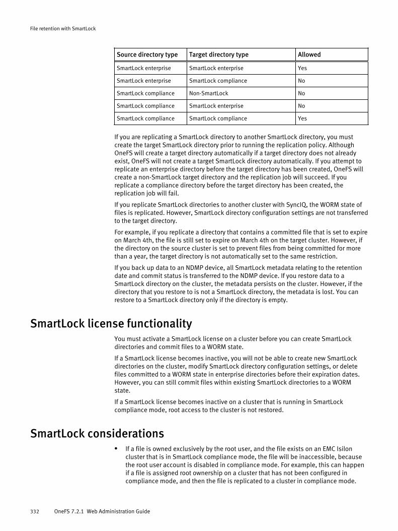
Source directory type Target directory type Allowed
SmartLock enterprise SmartLock enterprise Yes
SmartLock enterprise SmartLock compliance No
SmartLock compliance Non-SmartLock No
SmartLock compliance SmartLock enterprise No
SmartLock compliance SmartLock compliance Yes
If you are replicating a SmartLock directory to another SmartLock directory, you mustcreate the target SmartLock directory prior to running the replication policy. AlthoughOneFS will create a target directory automatically if a target directory does not alreadyexist, OneFS will not create a target SmartLock directory automatically. If you attempt toreplicate an enterprise directory before the target directory has been created, OneFS willcreate a non-SmartLock target directory and the replication job will succeed. If youreplicate a compliance directory before the target directory has been created, thereplication job will fail.
If you replicate SmartLock directories to another cluster with SyncIQ, the WORM state offiles is replicated. However, SmartLock directory configuration settings are not transferredto the target directory.
For example, if you replicate a directory that contains a committed file that is set to expireon March 4th, the file is still set to expire on March 4th on the target cluster. However, ifthe directory on the source cluster is set to prevent files from being committed for morethan a year, the target directory is not automatically set to the same restriction.
If you back up data to an NDMP device, all SmartLock metadata relating to the retentiondate and commit status is transferred to the NDMP device. If you restore data to aSmartLock directory on the cluster, the metadata persists on the cluster. However, if thedirectory that you restore to is not a SmartLock directory, the metadata is lost. You canrestore to a SmartLock directory only if the directory is empty.
SmartLock license functionalityYou must activate a SmartLock license on a cluster before you can create SmartLockdirectories and commit files to a WORM state.
If a SmartLock license becomes inactive, you will not be able to create new SmartLockdirectories on the cluster, modify SmartLock directory configuration settings, or deletefiles committed to a WORM state in enterprise directories before their expiration dates.However, you can still commit files within existing SmartLock directories to a WORMstate.
If a SmartLock license becomes inactive on a cluster that is running in SmartLockcompliance mode, root access to the cluster is not restored.
SmartLock considerationsl If a file is owned exclusively by the root user, and the file exists on an EMC Isilon
cluster that is in SmartLock compliance mode, the file will be inaccessible, becausethe root user account is disabled in compliance mode. For example, this can happenif a file is assigned root ownership on a cluster that has not been configured incompliance mode, and then the file is replicated to a cluster in compliance mode.
File retention with SmartLock
332 OneFS 7.2.1 Web Administration Guide

This can also occur if a root-owned file is restored onto a compliance cluster from abackup.
l It is recommended that you create files outside of SmartLock directories and thentransfer them into a SmartLock directory after you are finished working with the files.If you are uploading files to a cluster, it is recommended that you upload the files to anon-SmartLock directory, and then later transfer the files to a SmartLock directory. If afile is committed to a WORM state while the file is being uploaded, the file willbecome trapped in an inconsistent state.
l Files can be committed to a WORM state while they are still open. If you specify anautocommit time period for a directory, the autocommit time period is calculatedaccording to the length of time since the file was last modified, not when the file wasclosed. If you delay writing to an open file for more than the autocommit time period,the file is automatically committed to a WORM state, and you will not be able to writeto the file.
l In a Microsoft Windows environment, if you commit a file to a WORM state, you canno longer modify the hidden or archive attributes of the file. Any attempt to modifythe hidden or archive attributes of a WORM committed file generates an error. Thiscan prevent third-party applications from modifying the hidden or archive attributes.
Set the compliance clockBefore you can create SmartLock compliance directories, you must set the complianceclock. This procedure is available only through the command-line interface (CLI).
Setting the compliance clock configures the clock to the same time as the cluster systemclock. Before you set the compliance clock, ensure that the system clock is set to thecorrect time. If the compliance clock later becomes unsynchronized with the systemclock, the compliance clock will slowly correct itself to match the system clock. Thecompliance clock corrects itself at a rate of approximately one week per year.
Procedure
1. Open a secure shell (SSH) connection to any node in the cluster and log in through thecompliance administrator account.
2. Set the compliance clock by running the following command.
isi worm cdate set
View the compliance clockYou can view the current time of the compliance clock. This procedure is available onlythrough the command-line interface (CLI).
Procedure
1. Open a secure shell (SSH) connection to any node in the cluster and log in through thecompliance administrator account.
2. View the compliance clock by running the following command:
isi worm cdate view
File retention with SmartLock
Set the compliance clock 333
Creating a SmartLock directoryYou can create a SmartLock directory and configure settings that control how long filesare retained in a WORM state and when files are automatically committed to a WORMstate. You cannot move or rename a directory that contains a SmartLock directory.
It is recommended that you set SmartLock configuration settings only once and do notmodify the settings after files have been added to the SmartLock directory.
Retention periodsA retention period is the length of time that a file remains in a WORM state before beingreleased from a WORM state. You can configure SmartLock directory settings that enforcedefault, maximum, and minimum retention periods for the directory.
If you manually commit a file, you can optionally specify the date that the file is releasedfrom a WORM state. You can configure a minimum and a maximum retention period for aSmartLock directory to prevent files from being retained for too long or too short a timeperiod. It is recommended that you specify a minimum retention period for all SmartLockdirectories.
For example, assume that you have a SmartLock directory with a minimum retentionperiod of two days. At 1:00 PM on Monday, you commit a file to a WORM state, andspecify the file to be released from a WORM state on Tuesday at 3:00 PM. The file will bereleased from a WORM state two days later on Wednesday at 1:00 PM, because releasingthe file earlier would violate the minimum retention period.
You can also configure a default retention period that is assigned when you commit a filewithout specifying a date to release the file from a WORM state.
Autocommit time periodsYou can configure an autocommit time period for SmartLock directories. An autocommittime period causes files that have been in a SmartLock directory for a period of timewithout being modified to be automatically committed to a WORM state.
If you modify the autocommit time period of a SmartLock directory that containsuncommitted files, the new autocommit time period is immediately applied to the filesthat existed before the modification. For example, consider a SmartLock directory with anautocommit time period of 2 hours. If you modify a file in the SmartLock directory at 1:00PM, and you decrease the autocommit time period to 1 hour at 2:15 PM, the file isinstantly committed to a WORM state.
If a file is manually committed to a WORM state, the read-write permissions of the file aremodified. However, if a file is automatically committed to a WORM state, the read-writepermissions of the file are not modified.
Create a SmartLock directoryYou can create a SmartLock directory and commit files in that directory to a WORM state.This procedure is available only through the command-line interface (CLI).
Before creating a SmartLock directory, be aware of the following conditions andrequirements:
l You cannot create a SmartLock directory as a subdirectory of an existing SmartLockdirectory.
l Hard links cannot cross SmartLock directory boundaries.
File retention with SmartLock
334 OneFS 7.2.1 Web Administration Guide
l Creating a SmartLock directory causes a corresponding SmartLock domain to becreated for that directory.
Procedure
1. Open a secure shell (SSH) connection to any node in the cluster and log in.
2. Run the isi worm domains create command.
If you specify the path of an existing directory, the directory must be empty.
The following command creates a compliance directory with a default retention periodof four years, a minimum retention period of three years, and an maximum retentionperiod of five years:
sudo isi worm domains create /ifs/data/SmartLock/directory1 \--compliance --default-retention 4Y --min-retention 3Y \--max-retention 5Y --mkdir
The following command creates an enterprise directory with an autocommit timeperiod of thirty minutes and a minimum retention period of three months:
isi worm domains create /ifs/data/SmartLock/directory2 \--autocommit-offset 30m --min-retention 3M --mkdir
Managing SmartLock directoriesYou can modify SmartLock directory settings only 32 times per directory. SmartLockdirectory settings include the default, minimum, and maximum retention period and theautocommit time period.
A SmartLock directory can be renamed only if the directory is empty.
Modify a SmartLock directoryYou can modify the SmartLock configuration settings for a SmartLock directory. Thisprocedure is available only through the command-line interface (CLI).
Note
You can modify SmartLock directory settings only 32 times per directory. It isrecommended that you set SmartLock configuration settings only once and do not modifythe settings after files are added to the SmartLock directory.
Procedure
1. Open a secure shell (SSH) connection to any node in the cluster and log in.
2. Modify SmartLock configuration settings by running the isi worm modifycommand.
The following command sets the default retention period to one year:
isi worm domains modify /ifs/data/SmartLock/directory1 \--default-retention 1Y
File retention with SmartLock
Managing SmartLock directories 335
View SmartLock directory settingsYou can view the SmartLock directory settings for SmartLock directories. This procedureis available only through the command-line interface (CLI).
Procedure
1. Open a secure shell (SSH) connection to any node in the cluster and log in.2. View all SmartLock domains by running the following command:
isi worm domains list
The system displays output similar to the following example:
ID Path Type-----------------------------------------------65536 /ifs/data/SmartLock/directory1 enterprise65537 /ifs/data/SmartLock/directory2 enterprise65538 /ifs/data/SmartLock/directory3 enterprise-----------------------------------------------
3. (Optional) To view detailed information about a specific SmartLock directory, run theisi worm domains view command.
The following command displays detailed information about /ifs/data/SmartLock/directory2:
isi worm domains view /ifs/data/SmartLock/directory2
The system displays output similar to the following example:
ID: 65537 Path: /ifs/data/SmartLock/directory2 Type: enterprise LIN: 4295426060Autocommit Offset: 30m Override Date: -Privileged Delete: offDefault Retention: 1Y Min Retention: 3M Max Retention: - Total Modifies: 3/32 Max
SmartLock directory configuration settingsYou can configure SmartLock directory settings that determine when files are committedto and how long files are retained in a WORM state.
ID
The numerical ID of the corresponding SmartLock domain.
Path
The path of the directory.
Type
The type of SmartLock directory.
LIN
The inode number of the directory.
File retention with SmartLock
336 OneFS 7.2.1 Web Administration Guide

Autocommit offset
The autocommit time period for the directory. After a file exists in this SmartLockdirectory without being modified for the specified time period, the file isautomatically committed to a WORM state.Times are expressed in the format "<integer> <time>", where <time> is one of thefollowing values:
Y
Specifies years
M
Specifies months
W
Specifies weeks
D
Specifies days
H
Specifies hours
m
Specifies minutes
s
Specifies seconds
Override date
The override retention date for the directory. Files committed to a WORM state arenot released from a WORM state until after the specified date, regardless of themaximum retention period for the directory or whether a user specifies an earlierdate to release a file from a WORM state.
Privileged delete
Indicates whether files in the directory can be deleted through the privileged deletefunctionality.
on
The root user can delete files committed to a WORM state by running the isiworm files delete command.
off
WORM committed files cannot be deleted, even through the isi worm filesdelete command.
disabled
WORM committed files cannot be deleted, even through the isi worm filesdelete command. After this setting is applied, it cannot be modified.
Default retention period
The default retention period for the directory. If a user does not specify a date torelease a file from a WORM state, the default retention period is assigned.
File retention with SmartLock
SmartLock directory configuration settings 337
Times are expressed in the format "<integer> <time>", where <time> is one of thefollowing values:
Y
Specifies years
M
Specifies months
W
Specifies weeks
D
Specifies days
H
Specifies hours
m
Specifies minutes
s
Specifies seconds
Forever indicates that WORM committed files are retained permanently by default.Use Min indicates that the default retention period is equal to the minimumretention date. Use Max indicates that the default retention period is equal to themaximum retention date.
Minimum retention period
The minimum retention period for the directory. Files are retained in a WORM statefor at least the specified amount of time, even if a user specifies an expiration datethat results in a shorter retention period.Times are expressed in the format "<integer> <time>", where <time> is one of thefollowing values:
Y
Specifies years
M
Specifies months
W
Specifies weeks
D
Specifies days
H
Specifies hours
m
Specifies minutes
File retention with SmartLock
338 OneFS 7.2.1 Web Administration Guide

s
Specifies seconds
Forever indicates that all WORM committed files are retained permanently.
Maximum retention period
The maximum retention period for the directory. Files cannot be retained in a WORMstate for more than the specified amount of time, even if a user specifies anexpiration date that results in a longer retention period.Times are expressed in the format "<integer> <time>", where <time> is one of thefollowing values:
Y
Specifies years
M
Specifies months
W
Specifies weeks
D
Specifies days
H
Specifies hours
m
Specifies minutes
s
Specifies seconds
Forever indicates that there is no maximum retention period.
Total modifies
The total number of times that SmartLock settings have been modified for thedirectory. You can modify SmartLock settings only 32 times per directory.
Managing files in SmartLock directoriesYou can commit files in SmartLock directories to a WORM state by removing the read-write privileges of the file. You can also set a specific date at which the retention periodof the file expires. Once a file is committed to a WORM state, you can increase theretention period of the file, but you cannot decrease the retention period of the file. Youcannot move a file that has been committed to a WORM state, even after the retentionperiod for the file has expired.
The retention period expiration date is set by modifying the access time of a file. In aUNIX command line, the access time can be modified through the touch command.Although there is no method of modifying the access time through Windows Explorer, youcan modify the access time through Windows Powershell. Accessing a file does not setthe retention period expiration date.
File retention with SmartLock
Managing files in SmartLock directories 339
If you run the touch command on a file in a SmartLock directory without specifying adate on which to release the file from a SmartLock state, and you commit the file, theretention period is automatically set to the minimum retention period specified for theSmartLock directory. If you have not specified a minimum retention period for theSmartLock directory, the file is assigned a retention period of zero seconds. It isrecommended that you specify a minimum retention period for all SmartLock directories.
Set a retention period through a UNIX command lineYou can specify when a file will be released from a WORM state through a UNIX commandline.
Procedure
1. Open a connection to any node in the cluster through a UNIX command line and log in.
2. Set the retention period by modifying the access time of the file through the touchcommand.
The following command sets an expiration date of June 1, 2015 for /ifs/data/test.txt:
touch -at 201506010000 /ifs/data/test.txt
Set a retention period through Windows PowershellYou can specify when a file will be released from a WORM state through MicrosoftWindows Powershell.
Procedure
1. Open the Windows PowerShell command prompt.
2. (Optional) Establish a connection to the cluster by running the net use command.
The following command establishes a connection to the /ifs directory oncluster.ip.address.com:
net use "\\cluster.ip.address.com\ifs" /user:root password3. Specify the name of the file you want to set a retention period for by creating an
object.
The file must exist in a SmartLock directory.
The following command creates an object for /smartlock/file.txt:
$file = Get-Item "\\cluster.ip.address.com\ifs\smartlock\file.txt" 4. Specify the retention period by setting the last access time for the file.
The following command sets an expiration date of July 1, 2015 at 1:00 PM:
$file.LastAccessTime = Get-Date "2015/7/1 1:00 pm"
Commit a file to a WORM state through a UNIX command lineYou can commit a file to a WORM state through a UNIX command line.
To commit a file to a WORM state, you must remove all write privileges from the file. If afile is already set to a read-only state, you must first add write privileges to the file, andthen return the file to a read-only state.
File retention with SmartLock
340 OneFS 7.2.1 Web Administration Guide
Procedure
1. Open a connection to the cluster through a UNIX command line interface and log in.
2. Remove write privileges from a file by running the chmod command.
The following command removes write privileges of /ifs/data/smartlock/file.txt:
chmod ugo-w /ifs/data/smartlock/file.txt
Commit a file to a WORM state through Windows ExplorerYou can commit a file to a WORM state through Microsoft Windows Explorer. Thisprocedure describes how to commit a file through Windows 7.
To commit a file to a WORM state, you must apply the read-only setting. If a file is alreadyset to a read-only state, you must first remove the file from a read-only state and thenreturn it to a read-only state.
Procedure
1. In Windows Explorer, navigate to the file you want to commit to a WORM state.
2. Right-click the folder and then click Properties.
3. In the Properties window, click the General tab.
4. Select the Read-only check box, and then click OK.
Override the retention period for all files in a SmartLock directoryYou can override the retention period for files in a SmartLock directory. All filescommitted to a WORM state within the directory will remain in a WORM state until afterthe specified day. This procedure is available only through the command-line interface(CLI).
If files are committed to a WORM state after the retention period is overridden, theoverride date functions as a minimum retention date. All files committed to a WORM statedo not expire until at least the given day, regardless of user specifications.
Procedure
1. Open a secure shell (SSH) connection to any node in the cluster and log in.
2. Override the retention period expiration date for all WORM committed files in aSmartLock directory by running the isi worm modify command.
For example, the following command overrides the retention period expiration dateof /ifs/data/SmartLock/directory1 to June 1, 2014:
isi worm domains modify /ifs/data/SmartLock/directory1 \--override-date 2014-06-01
Delete a file committed to a WORM stateYou can delete a WORM committed file before the expiration date only if you are logged inas the root user or compliance administrator. This procedure is available only through thecommand-line interface (CLI).
Before you begin
Privileged delete functionality must not be permanently disabled for the SmartLockdirectory that contains the file.
File retention with SmartLock
Commit a file to a WORM state through Windows Explorer 341

Procedure
1. Open a connection to the cluster through a UNIX command line and log in througheither the root user or compliance administrator account.
2. If privileged delete functionality was disabled for the SmartLock directory, modify thedirectory by running the isi worm domains modify command with the --privileged-delete option.
The following command enables privileged delete for /ifs/data/SmartLock/directory1:
isi worm domains modify /ifs/data/SmartLock/directory1 \--privileged-delete true
3. Delete the WORM committed file by running the isi worm files deletecommand.
The following command deletes /ifs/data/SmartLock/directory1/file:
isi worm files delete /ifs/data/SmartLock/directory1/file
The system displays output similar to the following:
Are you sure? (yes, [no]):4. Type yes and then press ENTER.
View WORM status of a fileYou can view the WORM status of an individual file. This procedure is available onlythrough the command-line interface (CLI).
Procedure
1. Open a connection to the cluster through a UNIX command line.
2. View the WORM status of a file by running the isi worm files view command.
For example, the following command displays the WORM status of a file:
isi worm files view /ifs/data/SmartLock/directory1/file
The system displays output similar to the following:
WORM DomainsID Root Path------------------------------------65539 /ifs/data/SmartLock/directory1
WORM State: COMMITTED Expires: 2015-06-01T00:00:00
File retention with SmartLock
342 OneFS 7.2.1 Web Administration Guide
CHAPTER 18
Protection domains
This section contains the following topics:
l Protection domains overview.............................................................................. 344l Protection domain considerations.......................................................................344l Create a protection domain................................................................................. 345l Delete a protection domain................................................................................. 345
Protection domains 343
Protection domains overviewProtection domains are markers that prevent modifications to files and directories. If adomain is applied to a directory, the domain is also applied to all of the files andsubdirectories under the directory. You can specify domains manually; however, OneFSusually creates domains automatically.
There are three types of domains: SyncIQ, SmartLock, and SnapRevert. SyncIQ domainscan be assigned to source and target directories of replication policies. OneFSautomatically creates a SyncIQ domain for the target directory of a replication policy thefirst time that the policy is run. OneFS also automatically creates a SyncIQ domain for thesource directory of a replication policy during the failback process. You can manuallycreate a SyncIQ domain for a source directory before you initiate the failback process, butyou cannot delete a SyncIQ domain that marks the target directory of a replication policy.
SmartLock domains are assigned to SmartLock directories to prevent committed filesfrom being modified or deleted. OneFS automatically creates a SmartLock domain when aSmartLock directory is created. You cannot delete a SmartLock domain. However, if youdelete a SmartLock directory, OneFS automatically deletes the SmartLock domainassociated with the directory.
SnapRevert domains are assigned to directories that are contained in snapshots toprevent files and directories from being modified while a snapshot is being reverted.OneFS does not automatically create SnapRevert domains. You cannot revert a snapshotuntil you create a SnapRevert domain for the directory that the snapshot contains. Youcan create SnapRevert domains for subdirectories of directories that already haveSnapRevert domains. For example, you could create SnapRevert domains for both /ifs/data and /ifs/data/archive. You can delete a SnapRevert domain if you no longerwant to revert snapshots of a directory.
Protection domain considerationsYou can manually create protection domains before they are required by OneFS toperform certain actions. However, manually creating protection domains can limit yourability to interact with the data marked by the domain.
l Copying a large number of files into a protection domain might take a very long timebecause each file must be marked individually as belonging to the protectiondomain.
l You cannot move directories in or out of protection domains. However, you can movea directory contained in a protection domain to another location within the sameprotection domain.
l Creating a protection domain for a directory that contains a large number of files willtake more time than creating a protection domain for a directory with fewer files.Because of this, it is recommended that you create protection domains for directorieswhile the directories are empty, and then add files to the directory.
l If a domain is currently preventing the modification or deletion of a file, you cannotcreate a protection domain for a directory that contains that file. For example,if /ifs/data/smartlock/file.txt is set to a WORM state by a SmartLockdomain, you cannot create a SnapRevert domain for /ifs/data/.
Protection domains
344 OneFS 7.2.1 Web Administration Guide
Create a protection domainYou can create replication or snapshot revert domains to facilitate snapshot revert andfailover operations. You cannot create a SmartLock domain. OneFS automatically createsa SmartLock domain when you create a SmartLock directory.
Procedure
1. Click Cluster Management > Job Operations > Job Types.
2. In the Job Types area, in the DomainMark row, from the Actions column, select StartJob.
3. In the Domain Root Path field, type the path of the directory you want to create aprotection domain for.
4. From the Type of domain list, specify the type of domain you want to create.
5. Ensure that the Delete this domain check box is cleared.
6. Click Start Job.
Delete a protection domainYou can delete a replication or snapshot revert domain if you want to move directoriesout of the domain. You cannot delete a SmartLock domain. OneFS automatically deletes aSmartLock domain when you delete a SmartLock directory.
Procedure
1. Click Cluster Management > Job Operations > Job Types.
2. In the Job Types area, in the DomainMark row, from the Actions column, select StartJob.
3. In the Domain Root Path field, type the path of the directory you want to delete aprotection domain for.
4. From the Type of domain list, specify the type of domain you want to delete.
5. Select Delete this domain.
6. Click Start Job.
Protection domains
Create a protection domain 345

Protection domains
346 OneFS 7.2.1 Web Administration Guide
CHAPTER 19
Data-at-rest-encryption
This section contains the following topics:
l Data-at-rest encryption overview......................................................................... 348l Self-encrypting drives..........................................................................................348l Data security on self-encrypted drives................................................................. 348l Data migration to a self-encrypted-drives cluster................................................. 349l Chassis and drive states..................................................................................... 349l Smartfailed drive REPLACE state..........................................................................352l Smartfailed drive ERASE state............................................................................. 353
Data-at-rest-encryption 347
Data-at-rest encryption overviewYou can enhance data security with a EMC Isilon cluster that contains only self-encrypting-drive nodes, providing data-at-rest protection.
The OneFS system is available as a cluster that is composed of Isilon OneFS nodes thatcontain only self-encrypting drives (SEDs). The system requirements and management ofdata at rest on self-encrypting nodes are identical to that of nodes that do not containself-encrypting drives. Clusters of mixed node types are not supported.
Self-encrypting drivesSelf-encrypting drives store data on a EMC Isilon cluster that is specially designed fordata-at-rest encryption.
Data-at-rest- encryption on self-encrypted drives occurs when data that is stored on adevice is encrypted to prevent unauthorized data access. All data written to the storagedevice is encrypted when it is stored, and all data read from the storage device isdecrypted when it is read. The stored data is encrypted with a 256-bit data AESencryption key and decrypted in the same manner. OneFS controls data access bycombining the drive authentication key with on-disk data-encryption keys.
Note
All nodes in a cluster must be of the self-encrypting drive type. Mixed nodes are notsupported.
Data security on self-encrypted drivesSmartfailing self-encrypted drives guarantees data security after removal.
Data on self-encrypted drives is protected from unauthorized access by authenticatingencryption keys. Encryption keys never leave the drive. When a drive is locked, successfulauthentication unlocks the drive for data access.
The data on self-encrypted drives is rendered inaccessible in the following conditions:
l When a self-encrypting drive is smartfailed, drive authentication keys are deletedfrom the node. The data on the drive cannot be decrypted and is thereforeunreadable, which secures the drive.
l When a drive is smartfailed and removed from a node, the encryption key on the driveis removed. Because the encryption key for reading data from the drive must be thesame key that was used when the data was written, it is impossible to decrypt datathat was previously written to the drive. When you smartfail and then remove a drive,it is cryptographically erased.
Note
Smartfailing a drive is the preferred method for removing a self-encrypted drive.Removing a node that has been smartfailed guarantees that data is inaccessible.
l When a self-encrypting drive loses power, the drive locks to prevent unauthorizedaccess. When power is restored, data is again accessible when the appropriate driveauthentication key is provided.
Data-at-rest-encryption
348 OneFS 7.2.1 Web Administration Guide
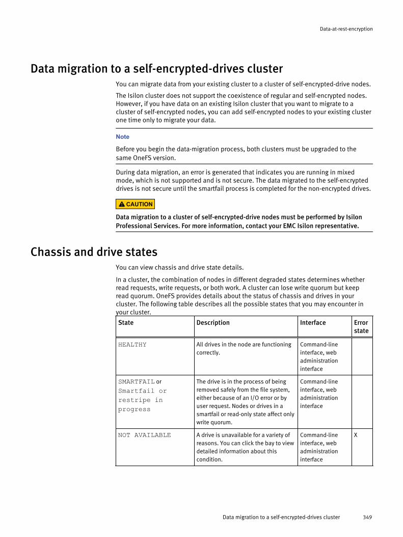
Data migration to a self-encrypted-drives clusterYou can migrate data from your existing cluster to a cluster of self-encrypted-drive nodes.
The Isilon cluster does not support the coexistence of regular and self-encrypted nodes.However, if you have data on an existing Isilon cluster that you want to migrate to acluster of self-encrypted nodes, you can add self-encrypted nodes to your existing clusterone time only to migrate your data.
Note
Before you begin the data-migration process, both clusters must be upgraded to thesame OneFS version.
During data migration, an error is generated that indicates you are running in mixedmode, which is not supported and is not secure. The data migrated to the self-encrypteddrives is not secure until the smartfail process is completed for the non-encrypted drives.
CAUTION
Data migration to a cluster of self-encrypted-drive nodes must be performed by IsilonProfessional Services. For more information, contact your EMC Isilon representative.
Chassis and drive statesYou can view chassis and drive state details.
In a cluster, the combination of nodes in different degraded states determines whetherread requests, write requests, or both work. A cluster can lose write quorum but keepread quorum. OneFS provides details about the status of chassis and drives in yourcluster. The following table describes all the possible states that you may encounter inyour cluster.
State Description Interface Errorstate
HEALTHY All drives in the node are functioningcorrectly.
Command-lineinterface, webadministrationinterface
SMARTFAIL or
Smartfail orrestripe inprogress
The drive is in the process of beingremoved safely from the file system,either because of an I/O error or byuser request. Nodes or drives in asmartfail or read-only state affect onlywrite quorum.
Command-lineinterface, webadministrationinterface
NOT AVAILABLE A drive is unavailable for a variety ofreasons. You can click the bay to viewdetailed information about thiscondition.
Command-lineinterface, webadministrationinterface
X
Data-at-rest-encryption
Data migration to a self-encrypted-drives cluster 349
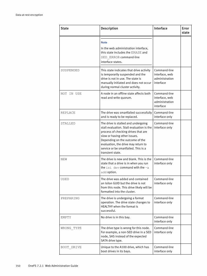
State Description Interface Errorstate
Note
In the web administration interface,this state includes the ERASE and
SED_ERROR command-line
interface states.
SUSPENDED This state indicates that drive activityis temporarily suspended and thedrive is not in use. The state ismanually initiated and does not occurduring normal cluster activity.
Command-lineinterface, webadministrationinterface
NOT IN USE A node in an offline state affects bothread and write quorum.
Command-lineinterface, webadministrationinterface
REPLACE The drive was smartfailed successfullyand is ready to be replaced.
Command-lineinterface only
STALLED The drive is stalled and undergoingstall evaluation. Stall evaluation is theprocess of checking drives that areslow or having other issues.Depending on the outcome of theevaluation, the drive may return toservice or be smartfailed. This is atransient state.
Command-lineinterface only
NEW The drive is new and blank. This is thestate that a drive is in when you runthe isi dev command with the -aadd option.
Command-lineinterface only
USED The drive was added and containedan Isilon GUID but the drive is notfrom this node. This drive likely will beformatted into the cluster.
Command-lineinterface only
PREPARING The drive is undergoing a formatoperation. The drive state changes toHEALTHY when the format issuccessful.
Command-lineinterface only
EMPTY No drive is in this bay. Command-lineinterface only
WRONG_TYPE The drive type is wrong for this node.For example, a non-SED drive in a SEDnode, SAS instead of the expectedSATA drive type.
Command-lineinterface only
BOOT_DRIVE Unique to the A100 drive, which hasboot drives in its bays.
Command-lineinterface only
Data-at-rest-encryption
350 OneFS 7.2.1 Web Administration Guide
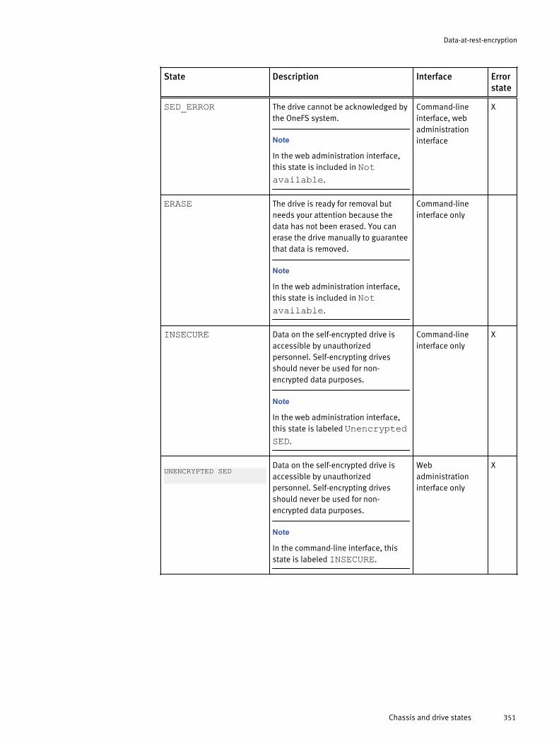
State Description Interface Errorstate
SED_ERROR The drive cannot be acknowledged bythe OneFS system.
Note
In the web administration interface,this state is included in Notavailable.
Command-lineinterface, webadministrationinterface
X
ERASE The drive is ready for removal butneeds your attention because thedata has not been erased. You canerase the drive manually to guaranteethat data is removed.
Note
In the web administration interface,this state is included in Notavailable.
Command-lineinterface only
INSECURE Data on the self-encrypted drive isaccessible by unauthorizedpersonnel. Self-encrypting drivesshould never be used for non-encrypted data purposes.
Note
In the web administration interface,this state is labeled UnencryptedSED.
Command-lineinterface only
X
UNENCRYPTED SED
Data on the self-encrypted drive isaccessible by unauthorizedpersonnel. Self-encrypting drivesshould never be used for non-encrypted data purposes.
Note
In the command-line interface, thisstate is labeled INSECURE.
Webadministrationinterface only
X
Data-at-rest-encryption
Chassis and drive states 351
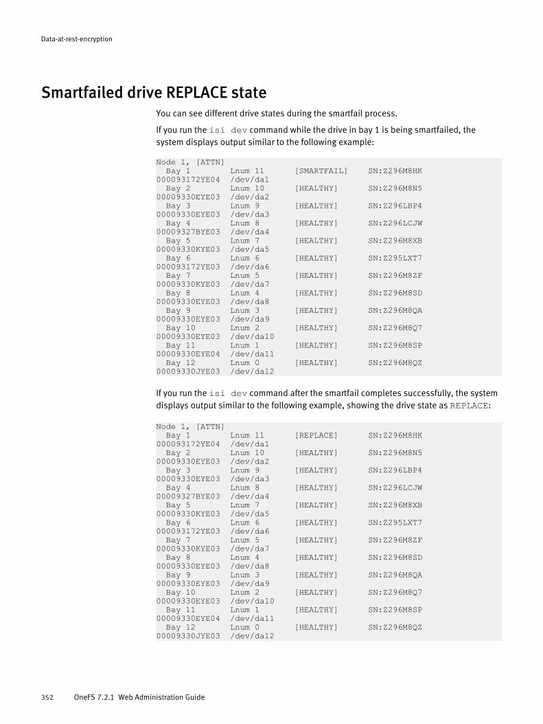
Smartfailed drive REPLACE stateYou can see different drive states during the smartfail process.
If you run the isi dev command while the drive in bay 1 is being smartfailed, thesystem displays output similar to the following example:
Node 1, [ATTN] Bay 1 Lnum 11 [SMARTFAIL] SN:Z296M8HK 000093172YE04 /dev/da1 Bay 2 Lnum 10 [HEALTHY] SN:Z296M8N5 00009330EYE03 /dev/da2 Bay 3 Lnum 9 [HEALTHY] SN:Z296LBP4 00009330EYE03 /dev/da3 Bay 4 Lnum 8 [HEALTHY] SN:Z296LCJW 00009327BYE03 /dev/da4 Bay 5 Lnum 7 [HEALTHY] SN:Z296M8XB 00009330KYE03 /dev/da5 Bay 6 Lnum 6 [HEALTHY] SN:Z295LXT7 000093172YE03 /dev/da6 Bay 7 Lnum 5 [HEALTHY] SN:Z296M8ZF 00009330KYE03 /dev/da7 Bay 8 Lnum 4 [HEALTHY] SN:Z296M8SD 00009330EYE03 /dev/da8 Bay 9 Lnum 3 [HEALTHY] SN:Z296M8QA 00009330EYE03 /dev/da9 Bay 10 Lnum 2 [HEALTHY] SN:Z296M8Q7 00009330EYE03 /dev/da10 Bay 11 Lnum 1 [HEALTHY] SN:Z296M8SP 00009330EYE04 /dev/da11 Bay 12 Lnum 0 [HEALTHY] SN:Z296M8QZ 00009330JYE03 /dev/da12
If you run the isi dev command after the smartfail completes successfully, the systemdisplays output similar to the following example, showing the drive state as REPLACE:
Node 1, [ATTN] Bay 1 Lnum 11 [REPLACE] SN:Z296M8HK 000093172YE04 /dev/da1 Bay 2 Lnum 10 [HEALTHY] SN:Z296M8N5 00009330EYE03 /dev/da2 Bay 3 Lnum 9 [HEALTHY] SN:Z296LBP4 00009330EYE03 /dev/da3 Bay 4 Lnum 8 [HEALTHY] SN:Z296LCJW 00009327BYE03 /dev/da4 Bay 5 Lnum 7 [HEALTHY] SN:Z296M8XB 00009330KYE03 /dev/da5 Bay 6 Lnum 6 [HEALTHY] SN:Z295LXT7 000093172YE03 /dev/da6 Bay 7 Lnum 5 [HEALTHY] SN:Z296M8ZF 00009330KYE03 /dev/da7 Bay 8 Lnum 4 [HEALTHY] SN:Z296M8SD 00009330EYE03 /dev/da8 Bay 9 Lnum 3 [HEALTHY] SN:Z296M8QA 00009330EYE03 /dev/da9 Bay 10 Lnum 2 [HEALTHY] SN:Z296M8Q7 00009330EYE03 /dev/da10 Bay 11 Lnum 1 [HEALTHY] SN:Z296M8SP 00009330EYE04 /dev/da11 Bay 12 Lnum 0 [HEALTHY] SN:Z296M8QZ 00009330JYE03 /dev/da12
Data-at-rest-encryption
352 OneFS 7.2.1 Web Administration Guide
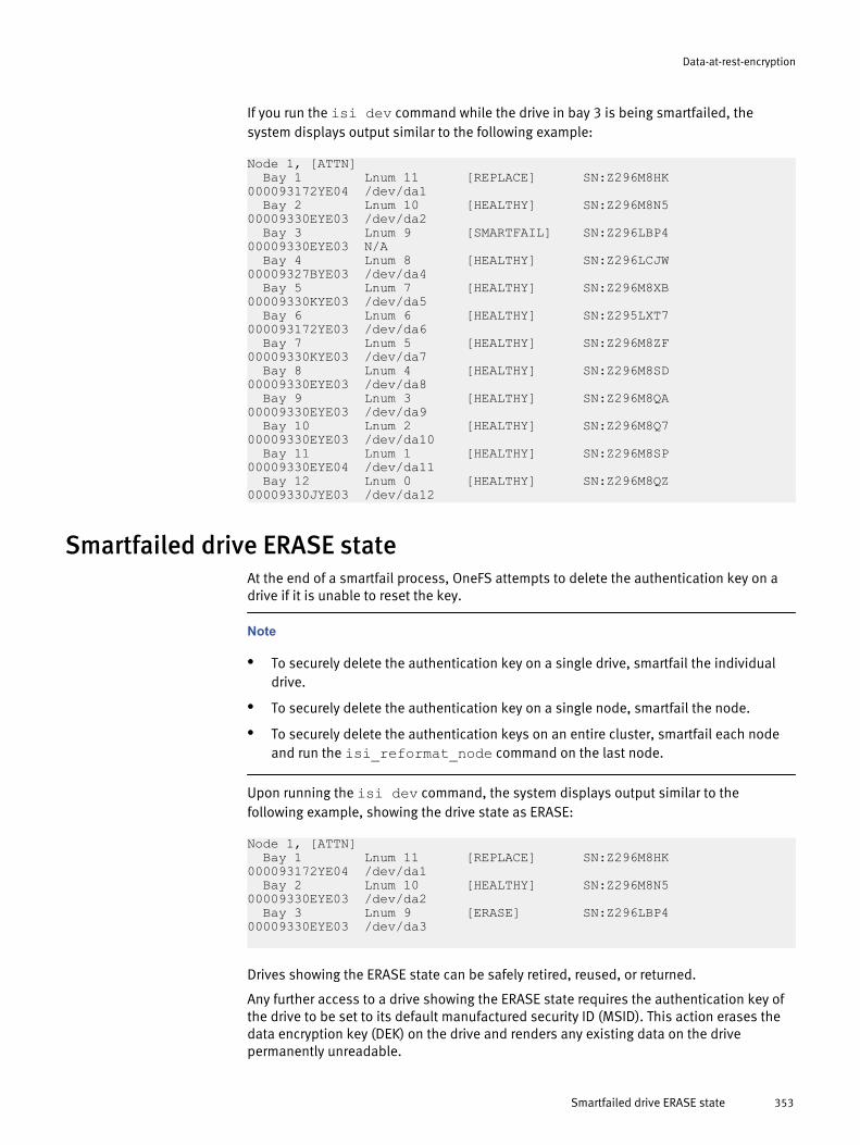
If you run the isi dev command while the drive in bay 3 is being smartfailed, thesystem displays output similar to the following example:
Node 1, [ATTN] Bay 1 Lnum 11 [REPLACE] SN:Z296M8HK 000093172YE04 /dev/da1 Bay 2 Lnum 10 [HEALTHY] SN:Z296M8N5 00009330EYE03 /dev/da2 Bay 3 Lnum 9 [SMARTFAIL] SN:Z296LBP4 00009330EYE03 N/A Bay 4 Lnum 8 [HEALTHY] SN:Z296LCJW 00009327BYE03 /dev/da4 Bay 5 Lnum 7 [HEALTHY] SN:Z296M8XB 00009330KYE03 /dev/da5 Bay 6 Lnum 6 [HEALTHY] SN:Z295LXT7 000093172YE03 /dev/da6 Bay 7 Lnum 5 [HEALTHY] SN:Z296M8ZF 00009330KYE03 /dev/da7 Bay 8 Lnum 4 [HEALTHY] SN:Z296M8SD 00009330EYE03 /dev/da8 Bay 9 Lnum 3 [HEALTHY] SN:Z296M8QA 00009330EYE03 /dev/da9 Bay 10 Lnum 2 [HEALTHY] SN:Z296M8Q7 00009330EYE03 /dev/da10 Bay 11 Lnum 1 [HEALTHY] SN:Z296M8SP 00009330EYE04 /dev/da11 Bay 12 Lnum 0 [HEALTHY] SN:Z296M8QZ 00009330JYE03 /dev/da12
Smartfailed drive ERASE stateAt the end of a smartfail process, OneFS attempts to delete the authentication key on adrive if it is unable to reset the key.
Note
l To securely delete the authentication key on a single drive, smartfail the individualdrive.
l To securely delete the authentication key on a single node, smartfail the node.
l To securely delete the authentication keys on an entire cluster, smartfail each nodeand run the isi_reformat_node command on the last node.
Upon running the isi dev command, the system displays output similar to thefollowing example, showing the drive state as ERASE:
Node 1, [ATTN] Bay 1 Lnum 11 [REPLACE] SN:Z296M8HK 000093172YE04 /dev/da1 Bay 2 Lnum 10 [HEALTHY] SN:Z296M8N5 00009330EYE03 /dev/da2 Bay 3 Lnum 9 [ERASE] SN:Z296LBP4 00009330EYE03 /dev/da3
Drives showing the ERASE state can be safely retired, reused, or returned.
Any further access to a drive showing the ERASE state requires the authentication key ofthe drive to be set to its default manufactured security ID (MSID). This action erases thedata encryption key (DEK) on the drive and renders any existing data on the drivepermanently unreadable.
Data-at-rest-encryption
Smartfailed drive ERASE state 353

Data-at-rest-encryption
354 OneFS 7.2.1 Web Administration Guide
CHAPTER 20
SmartQuotas
This section contains the following topics:
l SmartQuotas overview........................................................................................ 356l Quota types........................................................................................................ 356l Default quota type...............................................................................................357l Usage accounting and limits............................................................................... 359l Disk-usage calculations...................................................................................... 360l Quota notifications............................................................................................. 361l Quota notification rules.......................................................................................362l Quota reports......................................................................................................362l Creating quotas...................................................................................................363l Managing quotas................................................................................................ 364l Managing quota notifications..............................................................................367l Email quota notification messages......................................................................369l Managing quota reports...................................................................................... 372l Basic quota settings............................................................................................374l Advisory limit quota notification rules settings.................................................... 374l Soft limit quota notification rules settings........................................................... 375l Hard limit quota notification rules settings..........................................................375l Limit notification settings....................................................................................376l Quota report settings.......................................................................................... 376
SmartQuotas 355

SmartQuotas overviewThe SmartQuotas module is an optional quota-management tool that monitors andenforces administrator-defined storage limits. Using accounting and enforcement quotalimits, reporting capabilities, and automated notifications, SmartQuotas managesstorage use, monitors disk storage, and issues alerts when disk-storage limits areexceeded.
Quotas help you manage storage usage according to criteria that you define. Quotas areused for tracking—and sometimes limiting—the amount of storage that a user, group, orproject consumes. Quotas are a useful way of ensuring that a user or department doesnot infringe on the storage that is allocated to other users or departments. In some quotaimplementations, writes beyond the defined space are denied, and in other cases, asimple notification is sent.
Note
Do not apply quotas to /ifs/.ifsvar/ or its subdirectories. If you limit the size of
the /ifs/.ifsvar/ directory through a quota, and the directory reaches its limit, jobs suchas File-System Analytics fail. A quota blocks older job reports from being deleted fromthe /ifs/.ifsvar/ subdirectories to make room for newer reports.
The SmartQuotas module requires a separate license. For more information about theSmartQuotas module or to activate the module, contact your EMC Isilon salesrepresentative.
Quota typesOneFS uses the concept of quota types as the fundamental organizational unit of storagequotas. Storage quotas comprise a set of resources and an accounting of each resourcetype for that set. Storage quotas are also called storage domains.
Storage quotas creation requires three identifiers:l The directory to monitorl Whether snapshots are to be tracked against the quota limitl The quota type (directory, user, or group)
Note
You should not create quotas of any type on the OneFS root (/ifs). A root-level quota
may significantly degrade performance.
You can choose a quota type from the following entities:
Directory
A specific directory and its subdirectories.
User
Either a specific user or default user (every user). Specific-user quotas that youconfigure take precedence over a default user quota.
Group
All members of a specific group or all members of a default group (every group). Anyspecific-group quotas that you configure take precedence over a default groupquota. Associating a group quota with a default group quota creates a linked quota.
SmartQuotas
356 OneFS 7.2.1 Web Administration Guide

You can create multiple quota types on the same directory, but they must be of a differenttype or have a different snapshot option. You can specify quota types for any directory inOneFS and nest them within each other to create a hierarchy of complex storage-usepolicies.
Nested storage quotas can overlap. For example, the following quota settings ensure thatthe finance directory never exceeds 5 TB, while limiting the users in the financedepartment to 1 TB each:
l Set a 5 TB hard quota on /ifs/data/finance.
l Set 1 TB soft quotas on each user in the finance department.
Default quota typeDefault quotas automatically create other quotas for users or groups in a specifieddirectory.
A default quota specifies a policy for new entities that match a trigger. The default-user@/ifs/cs becomes specific-user@/ifs/cs for each specific-user that is not otherwisedefined.
For example, you can create a default-user quota on the /ifs/dir-1 directory, wherethat directory is owned by the root user. The default-user type automatically creates anew domain on that directory for root and adds the usage there:
my-OneFS-1# mkdir /ifs/dir-1my-OneFS-1# isi quota quotas create /ifs/dir-1 default-usermy-OneFS-1# isi quota quotas ls --path=/ifs/dir-1 Type AppliesTo Path Snap Hard Soft Adv Used---------------------------------------------------------------default-user DEFAULT /ifs/dir-1 No - - - 0buser root /ifs/dir-1 No - - - 0b---------------------------------------------------------------
Now add a file that is owned by a different user (admin).
my-OneFS-1# touch /ifs/dir-1/somefilemy-OneFS-1# chown admin /ifs/dir-1/somefilemy-OneFS-1# isi quota quotas ls --path=/ifs/dir-1Type AppliesTo Path Snap Hard Soft Adv Used---------------------------------------------------------------default-user DEFAULT /ifs/dir-1 No - - - 0buser root /ifs/dir-1 No - - - 26buser admin /ifs/dir-1 No - - - 0b---------------------------------------------------------------Total: 3
In this example, the default-user type created a new specific-user type automatically(user:admin) and added the new usage to it. Default-user does not have any usagebecause it is used only to generate new quotas automatically. Default-user enforcementis copied to a specific-user (user:admin), and the inherited quota is called a linked quota.In this way, each user account gets its own usage accounting.
Defaults can overlap. For example, default-user@/ifs/dir-1 and default-user@/ifs/csboth may be defined. If the default enforcement changes, OneFS storage quotaspropagate the changes to the linked quotas asynchronously. Because the update isasynchronous, there is some delay before updates are in effect. If a default type, such asevery user or every group, is deleted, OneFS deletes all children that are marked asinherited. As an option, you can delete the default without deleting the children, but it isimportant to note that this action breaks inheritance on all inherited children.
SmartQuotas
Default quota type 357
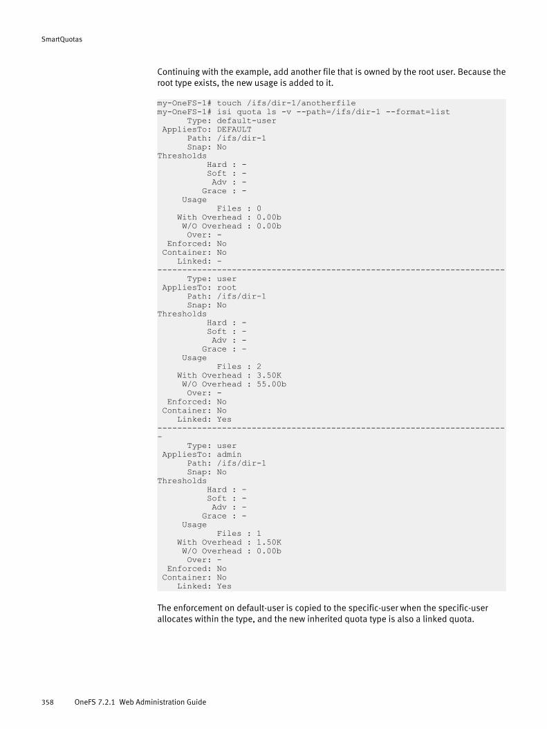
Continuing with the example, add another file that is owned by the root user. Because theroot type exists, the new usage is added to it.
my-OneFS-1# touch /ifs/dir-1/anotherfilemy-OneFS-1# isi quota ls -v --path=/ifs/dir-1 --format=list Type: default-user AppliesTo: DEFAULT Path: /ifs/dir-1 Snap: NoThresholds Hard : - Soft : - Adv : - Grace : - Usage Files : 0 With Overhead : 0.00b W/O Overhead : 0.00b Over: - Enforced: No Container: No Linked: ----------------------------------------------------------------------- Type: user AppliesTo: root Path: /ifs/dir-1 Snap: NoThresholds Hard : - Soft : - Adv : - Grace : - Usage Files : 2 With Overhead : 3.50K W/O Overhead : 55.00b Over: - Enforced: No Container: No Linked: Yes----------------------------------------------------------------------- Type: user AppliesTo: admin Path: /ifs/dir-1 Snap: NoThresholds Hard : - Soft : - Adv : - Grace : - Usage Files : 1 With Overhead : 1.50K W/O Overhead : 0.00b Over: - Enforced: No Container: No Linked: Yes
The enforcement on default-user is copied to the specific-user when the specific-userallocates within the type, and the new inherited quota type is also a linked quota.
SmartQuotas
358 OneFS 7.2.1 Web Administration Guide

Note
Configuration changes for linked quotas must be made on the parent quota that thelinked quota is inheriting from. Changes to the parent quota are propagated to allchildren. To override configuration from the parent quota, you must unlink the quota first.
Usage accounting and limitsStorage quotas support two usage types that you can create to manage storage space.The usage types are accounting and enforcement limits.
You can configure OneFS quotas by usage type to track or limit storage use. Theaccounting option, which monitors disk-storage use, is useful for auditing, planning, andbilling. Enforcement limits set storage limits for users, groups, or directories.
Accounting
The accounting option tracks but does not limit disk-storage use. Using theaccounting option for a quota, you can monitor inode count and physical and logicalspace resources. Physical space refers to all of the space used to store files anddirectories, including data and metadata in the domain. Logical space refers to thesum of all files sizes, excluding file metadata and sparse regions. User data storageis tracked using logical-space calculations, which do not include protectionoverhead. As an example, by using the accounting option, you can do the following:
l Track the amount of disk space used by various users or groups to bill each user,group, or directory for only the disk space used.
l Review and analyze reports that help you identify storage usage patterns anddefine storage policies.
l Plan for capacity and other storage needs.
Enforcement limits
Enforcement limits include all of the functionality of the accounting option, plus theability to limit disk storage and send notifications. Using enforcement limits, you canlogically partition a cluster to control or restrict how much storage that a user, group,or directory can use. For example, you can set hard- or soft-capacity limits to ensurethat adequate space is always available for key projects and critical applications andto ensure that users of the cluster do not exceed their allotted storage capacity.Optionally, you can deliver real-time email quota notifications to users, groupmanagers, or administrators when they are approaching or have exceeded a quotalimit.
Note
If a quota type uses the accounting-only option, enforcement limits cannot be used forthat quota.
The actions of an administrator logged in as root may push a domain over a quotathreshold. For example, changing the protection level or taking a snapshot has thepotential to exceed quota parameters. System actions such as repairs also may push aquota domain over the limit.
The system provides three types of administrator-defined enforcement thresholds.
SmartQuotas
Usage accounting and limits 359

Thresholdtype
Description
Hard Limits disk usage to a size that cannot be exceeded. If an operation, such as a filewrite, causes a quota target to exceed a hard quota, the following events occur:
l the operation fails
l an alert is logged to the cluster
l a notification is issued to specified recipients.
Writes resume when the usage falls below the threshold.
Soft Allows a limit with a grace period that can be exceeded until the grace periodexpires. When a soft quota is exceeded, an alert is logged to the cluster and anotification is issued to specified recipients; however, data writes are permittedduring the grace period.
If the soft threshold is still exceeded when the grace period expires, data writesfail, and a hard-limit notification is issued to the recipients you have specified.
Writes resume when the usage falls below the threshold.
Advisory An informational limit that can be exceeded. When an advisory quota threshold isexceeded, an alert is logged to the cluster and a notification is issued to specifiedrecipients. Advisory thresholds do not prevent data writes.
Disk-usage calculationsFor each quota that you configure, you can specify whether data-protection overhead isincluded in future disk-usage calculations.
Most quota configurations do not need to include overhead calculations. If you do notinclude data-protection overhead in usage calculations for a quota, future disk-usagecalculations for the quota include only the space that is required to store files anddirectories. Space that is required for the data-protection setting of the cluster is notincluded.
Consider the same example user, who is now restricted by a 40 GB quota that does notinclude data-protection overhead in its disk-usage calculations. If your cluster isconfigured with a 2x data-protection level and the user writes a 10 GB file to the cluster,that file consumes 20 GB of space but the 10GB for the data-protection overhead is notcounted in the quota calculation. In this example, the user has reached 25 percent of the40 GB quota by writing a 10 GB file to the cluster. This method of disk-usage calculationis recommended for most quota configurations.
If you include data-protection overhead in usage calculations for a quota, future disk-usage calculations for the quota include the total amount of space that is required tostore files and directories, in addition to any space that is required to accommodate yourdata-protection settings, such as parity or mirroring. For example, consider a user who isrestricted by a 40 GB quota that includes data-protection overhead in its disk-usagecalculations. If your cluster is configured with a 2x data-protection level (mirrored) andthe user writes a 10 GB file to the cluster, that file actually consumes 20 GB of space: 10GB for the file and 10 GB for the data-protection overhead. In this example, the user hasreached 50 percent of the 40 GB quota by writing a 10 GB file to the cluster.
SmartQuotas
360 OneFS 7.2.1 Web Administration Guide
Note
Cloned and deduplicated files are treated as ordinary files by quotas. If the quotaincludes data protection overhead, the data protection overhead for shared data is notincluded in the usage calculation.
You can configure quotas to include the space that is consumed by snapshots. A singlepath can have two quotas applied to it: one without snapshot usage, which is the default,and one with snapshot usage. If you include snapshots in the quota, more files areincluded in the calculation than are in the current directory. The actual disk usage is thesum of the current directory and any snapshots of that directory. You can see whichsnapshots are included in the calculation by examining the .snapshot directory for thequota path.
Note
Only snapshots created after the QuotaScan job finishes are included in the calculation.
Quota notificationsQuota notifications are generated for enforcement quotas, providing users withinformation when a quota violation occurs. Reminders are sent periodically while thecondition persists.
Each notification rule defines the condition that is to be enforced and the action that is tobe executed when the condition is true. An enforcement quota can define multiplenotification rules. When thresholds are exceeded, automatic email notifications can besent to specified users, or you can monitor notifications as system alerts or receiveemails for these events.
Notifications can be configured globally, to apply to all quota domains, or be configuredfor specific quota domains.
Enforcement quotas support the following notification settings. A given quota can useonly one of these settings.
Limit notification settings Description
Turn Off Notifications for thisQuota
Disables all notifications for the quota.
Use Default Notification Rules Uses the global default notification for the specified type ofquota.
Use Custom Notification Rules Enables the creation of advanced, custom notifications thatapply to the specific quota. Custom notifications can beconfigured for any or all of the threshold types (hard, soft, oradvisory) for the specified quota.
SmartQuotas
Quota notifications 361
Quota notification rulesYou can write quota notification rules to generate alerts that are triggered by eventthresholds.
When an event occurs, a notification is triggered according to your notification rule. Forexample, you can create a notification rule that sends an email when a disk-spaceallocation threshold is exceeded by a group.
You can configure notification rules to trigger an action according to event thresholds (anotification condition). A rule can specify a schedule, such as "every day at 1:00 AM," forexecuting an action or immediate notification of certain state transitions. When an eventoccurs, a notification trigger may execute one or more actions, such as sending an emailor sending a cluster alert to the interface. The following examples demonstrate the typesof criteria that you can use to configure notification rules.
l Notify when a threshold is exceeded; at most, once every 5 minutesl Notify when allocation is denied; at most, once an hourl Notify while over threshold, daily at 2 AMl Notify while grace period expired weekly, on Sundays at 2 AM
Notifications are triggered for events grouped by the following categories:
Instant notifications
Includes the write-denied notification, triggered when a hard threshold denies awrite, and the threshold-exceeded notification, triggered at the moment a hard, soft,or advisory threshold is exceeded. These are one-time notifications because theyrepresent a discrete event in time.
Ongoing notifications
Generated on a scheduled basis to indicate a persisting condition, such as a hard,soft, or advisory threshold being over a limit or a soft threshold's grace period beingexpired for a prolonged period.
Quota reportsThe OneFS SmartQuotas module provides reporting options that enable administrators tomanage cluster resources and analyze usage statistics.
Storage quota reports provide a summarized view of the past or present state of thequota domains. After raw reporting data is collected by OneFS, you can produce datasummaries by using a set of filtering parameters and sort types. Storage-quota reportsinclude information about violators, grouped by threshold types. You can generatereports from a historical data sample or from current data. In either case, the reports areviews of usage data at a given time. OneFS does not provide reports on data aggregatedover time, such as trending reports, but you can use raw data to analyze trends. There isno configuration limit on the number of reports other than the space needed to storethem.
OneFS provides the following data-collection and reporting methods:
l Scheduled reports are generated and saved on a regular interval.l Ad hoc reports are generated and saved at the request of the user.l Live reports are generated for immediate and temporary viewing.
Scheduled reports are placed by default in the /ifs/.isilon/smartquotas/reports directory, but the location is configurable to any directory under /ifs. Each
SmartQuotas
362 OneFS 7.2.1 Web Administration Guide

generated report includes quota domain definition, state, usage, and globalconfiguration settings. By default, ten reports are kept at a time, and older reports arepurged. You can create ad hoc reports at any time to view the current state of the storagequotas system. These live reports can be saved manually. Ad hoc reports are saved to alocation that is separate from scheduled reports to avoid skewing the timed-report sets.
Creating quotasYou can create two types of storage quotas to monitor data: accounting quotas andenforcement quotas. Storage quota limits and restrictions can apply to specific users,groups, or directories.
The type of quota that you create depends on your goal.
l Enforcement quotas monitor and limit disk usage. You can create enforcementquotas that use any combination of hard limits, soft limits, and advisory limits.
Note
Enforcement quotas are not recommended for snapshot-tracking quota domains.
l Accounting quotas monitor, but do not limit, disk usage.
Note
Before using quota data for analysis or other purposes, verify that no QuotaScan jobs arerunning.
Create an accounting quotaYou can create an accounting quota to monitor but not limit disk usage.
Optionally, you can include snapshot data, data-protection overhead, or both in theaccounting quota.
Procedure
1. Click File System Management > SmartQuotas > Quotas & Usage.
2. On the Storage Quotas & Usage page, click Create a storage quota.
3. From the Quota Type list, select the target for this quota: a directory, user, or group.
4. Depending on the target that you selected, select the entity that you want to apply thequota to. For example, if you selected User from the Quota Type list, you can targeteither all users or a specific user.
5. In the Directory path field, type the path and directory for the quota, or click Browse,and then select a directory.
6. (Optional) In the Usage Accounting area, select the options that you want.
l To include snapshot data in the accounting quota, select the Include SnapshotData check box.
l To include the data-protection overhead in the accounting quota, select theInclude Data-Protection Overhead check box.
l To include snapshot data in the accounting quota, select the Include SnapshotData check box.
7. In the Usage Limits area, click No Usage Limit (Accounting Only).
8. Click Create Quota.
SmartQuotas
Creating quotas 363

After you finish
Before using quota data for analysis or other purposes, verify that no QuotaScan jobs arein progress by checking Cluster Management > Job Operations > Job Summary.
Create an enforcement quotaYou can create an enforcement quota to monitor and limit disk usage.
You can create enforcement quotas that set hard, soft, and advisory limits.
Procedure
1. Click File System Management > SmartQuotas > Quotas & Usage.
2. On the Storage Quotas & Usage page, click Create a storage quota.
3. From the Quota Type list, select the target for this quota: a directory, user, or group.
4. Depending on the target that you selected, select the entity that you want to apply thequota to. For example, if you selected User from the Quota Type list, you can target allusers or a specific user.
5. In the Directory path field, type the path and directory for the quota, or click Browse,and then select a directory.
6. (Optional) In the Usage Accounting area, click the Include Snapshot Data check box,the Include Data-Protection Overhead check box, or both to include them in thequota.
7. In the Usage Limits area, click Specify Usage Limits.
8. Click the check box next to the option for each type of limit that you want to enforce.
9. Type numerals in the fields and select from the lists the values that you want to usefor the quota.
10. In the Limit Notifications area, click the notification option that you want to apply tothe quota.
11. To generate an event notification, select the Create cluster event check box.
12. (Optional) If you selected the option to use custom notification rules, click the link toexpand the custom notification type that applies to the usage-limit selections.
13. Click Create Quota.
After you finish
Before using quota data for analysis or other purposes, verify that no QuotaScan jobs arein progress by checking Cluster Management > Job Operations > Job Summary.
Managing quotasYou can modify the configured values of a storage quota, and you can enable or disable aquota. You can also create quota limits and restrictions that apply to specific users,groups, or directories.
Quota management in OneFS is simplified by the quota search feature, which helps youto locate a quota or quotas by using filters. You can unlink quotas that are associatedwith a parent quota, and configure custom notifications for quotas. You can also disablea quota temporarily and then enable it when needed.
Note
Moving quota directories across quota domains is not supported.
SmartQuotas
364 OneFS 7.2.1 Web Administration Guide
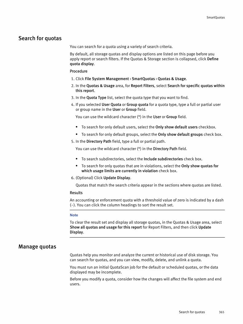
Search for quotasYou can search for a quota using a variety of search criteria.
By default, all storage quotas and display options are listed on this page before youapply report or search filters. If the Quotas & Storage section is collapsed, click Definequota display.
Procedure
1. Click File System Management > SmartQuotas > Quotas & Usage.
2. In the Quotas & Usage area, for Report Filters, select Search for specific quotas withinthis report.
3. In the Quota Type list, select the quota type that you want to find.
4. If you selected User Quota or Group quota for a quota type, type a full or partial useror group name in the User or Group field.
You can use the wildcard character (*) in the User or Group field.
l To search for only default users, select the Only show default users checkbox.
l To search for only default groups, select the Only show default groups check box.
5. In the Directory Path field, type a full or partial path.
You can use the wildcard character (*) in the Directory Path field.
l To search subdirectories, select the Include subdirectories check box.
l To search for only quotas that are in violations, select the Only show quotas forwhich usage limits are currently in violation check box.
6. (Optional) Click Update Display.
Quotas that match the search criteria appear in the sections where quotas are listed.
Results
An accounting or enforcement quota with a threshold value of zero is indicated by a dash(–). You can click the column headings to sort the result set.
Note
To clear the result set and display all storage quotas, in the Quotas & Usage area, selectShow all quotas and usage for this report for Report Filters, and then click UpdateDisplay.
Manage quotasQuotas help you monitor and analyze the current or historical use of disk storage. Youcan search for quotas, and you can view, modify, delete, and unlink a quota.
You must run an initial QuotaScan job for the default or scheduled quotas, or the datadisplayed may be incomplete.
Before you modify a quota, consider how the changes will affect the file system and endusers.
SmartQuotas
Search for quotas 365

Note
l The options to edit or delete a quota display only when the quota is not linked to adefault quota.
l The option to unlink a quota is available only when the quota is linked to a defaultquota.
Procedure
1. Click File System Management > SmartQuotas > Quotas & Usage.
2. From the Quota Report options, select the type of quota report that you want to viewor manage.
l To monitor and analyze current disk storage use, click Show current quotas andusage (Live Report).
l To monitor and analyze historical disk storage use, click Show archived quotareport to select from the list of archived scheduled and manually generated quotareports.
3. For Report Filters, select the filters to be used for this quota report.
l To view all information in the quota report, click Show all quotas and usage forthis report.
l To filter the quota report, click Search for specific quotas within this report, andthen select the filters that you want to apply.
4. Click Update Display.
5. (Optional) Select a quota to view its settings or to perform the following managementactions.
l To review or edit this quota, click View details.l To delete this quota, click Delete.l To unlink a linked quota, click Unlink.
Note
Configuration changes for linked quotas must be made on the parent (default)quota that the linked quota is inheriting from. Changes to the parent quota arepropagated to all children. If you want to override configuration from the parentquota, you must first unlink the quota.
Export a quota configuration fileYou can export quota settings as a configuration file, which can then be imported forreuse to another Isilon cluster. You can also store the exported quota configurations in alocation outside of the cluster. This task may only be performed from the OneFScommand line interface.
You can pipe the XML report to a file or directory. The file can then be imported to anothercluster.
Procedure
1. Open a secure shell (SSH) connection to any node in the cluster and log in.
2. At the command prompt, run the following command:
isi_classic quota list --export
SmartQuotas
366 OneFS 7.2.1 Web Administration Guide
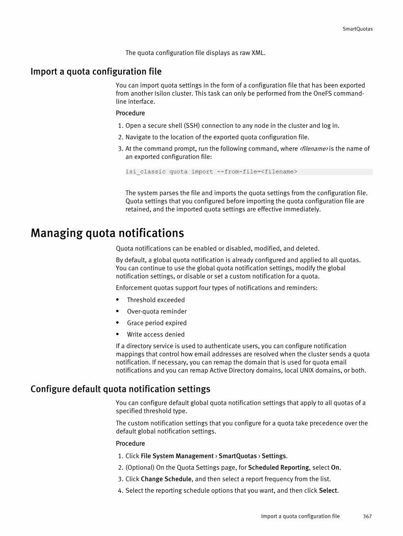
The quota configuration file displays as raw XML.
Import a quota configuration fileYou can import quota settings in the form of a configuration file that has been exportedfrom another Isilon cluster. This task can only be performed from the OneFS command-line interface.
Procedure
1. Open a secure shell (SSH) connection to any node in the cluster and log in.
2. Navigate to the location of the exported quota configuration file.
3. At the command prompt, run the following command, where <filename> is the name ofan exported configuration file:
isi_classic quota import --from-file=<filename>
The system parses the file and imports the quota settings from the configuration file.Quota settings that you configured before importing the quota configuration file areretained, and the imported quota settings are effective immediately.
Managing quota notificationsQuota notifications can be enabled or disabled, modified, and deleted.
By default, a global quota notification is already configured and applied to all quotas.You can continue to use the global quota notification settings, modify the globalnotification settings, or disable or set a custom notification for a quota.
Enforcement quotas support four types of notifications and reminders:
l Threshold exceeded
l Over-quota reminder
l Grace period expired
l Write access denied
If a directory service is used to authenticate users, you can configure notificationmappings that control how email addresses are resolved when the cluster sends a quotanotification. If necessary, you can remap the domain that is used for quota emailnotifications and you can remap Active Directory domains, local UNIX domains, or both.
Configure default quota notification settingsYou can configure default global quota notification settings that apply to all quotas of aspecified threshold type.
The custom notification settings that you configure for a quota take precedence over thedefault global notification settings.
Procedure
1. Click File System Management > SmartQuotas > Settings.
2. (Optional) On the Quota Settings page, for Scheduled Reporting, select On.
3. Click Change Schedule, and then select a report frequency from the list.
4. Select the reporting schedule options that you want, and then click Select.
SmartQuotas
Import a quota configuration file 367
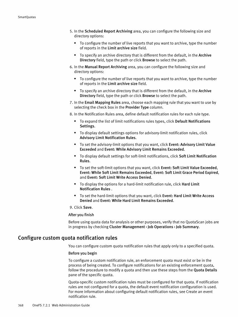
5. In the Scheduled Report Archiving area, you can configure the following size anddirectory options:
l To configure the number of live reports that you want to archive, type the numberof reports in the Limit archive size field.
l To specify an archive directory that is different from the default, in the ArchiveDirectory field, type the path or click Browse to select the path.
6. In the Manual Report Archiving area, you can configure the following size anddirectory options:
l To configure the number of live reports that you want to archive, type the numberof reports in the Limit archive size field.
l To specify an archive directory that is different from the default, in the ArchiveDirectory field, type the path or click Browse to select the path.
7. In the Email Mapping Rules area, choose each mapping rule that you want to use byselecting the check box in the Provider Type column.
8. In the Notification Rules area, define default notification rules for each rule type.
l To expand the list of limit notifications rules types, click Default NotificationsSettings.
l To display default settings options for advisory-limit notification rules, clickAdvisory Limit Notification Rules.
l To set the advisory-limit options that you want, click Event: Advisory Limit ValueExceeded and Event: While Advisory Limit Remains Exceeded.
l To display default settings for soft-limit notifications, click Soft Limit NotificationRules.
l To set the soft-limit options that you want, click Event: Soft Limit Value Exceeded,Event: While Soft Limit Remains Exceeded, Event: Soft Limit Grace Period Expired,and Event: Soft Limit Write Access Denied.
l To display the options for a hard-limit notification rule, click Hard LimitNotification Rules .
l To set the hard-limit options that you want, click Event: Hard Limit Write AccessDenied and Event: While Hard Limit Remains Exceeded.
9. Click Save.
After you finish
Before using quota data for analysis or other purposes, verify that no QuotaScan jobs arein progress by checking Cluster Management > Job Operations > Job Summary.
Configure custom quota notification rulesYou can configure custom quota notification rules that apply only to a specified quota.
Before you begin
To configure a custom notification rule, an enforcement quota must exist or be in theprocess of being created. To configure notifications for an existing enforcement quota,follow the procedure to modify a quota and then use these steps from the Quota Detailspane of the specific quota.
Quota-specific custom notification rules must be configured for that quota. If notificationrules are not configured for a quota, the default event notification configuration is used.For more information about configuring default notification rules, see Create an eventnotification rule.
SmartQuotas
368 OneFS 7.2.1 Web Administration Guide

Procedure
1. In the Limit Notifications area, click Use Custom Notification Rules.
The links display for the rules options that are available for the type of notificationthat you have selected for this quota.
2. Click the link for the limit notification type that you want to configure for this quota.From the list, select the target for this quota: a directory, user, or group.
The Limit Notification Rules options display for the selection type.
3. Select or type the values to configure the custom notification rule for this quota.
4. Click Create quota when you have completed configuring the settings for thisnotification rule.
Results
The quota appears in the Quotas & Usage list.
After you finish
Before using quota data for analysis or other purposes, verify that no QuotaScan jobs arein progress by checking Cluster Management > Job Operations > Job Summary.
Map an email notification rule for a quotaEmail notification mapping rules control how email addresses are resolved when thecluster sends a quota notification.
If necessary, you can remap the domain used for SmartQuotas email notifications. Youcan remap Active Directory Windows domains, local UNIX domains, or NIS domains.
Note
You must be logged in to the web administration interface to perform this task.
Procedure
1. Click File System Management > SmartQuotas > Settings.
2. (Optional) In the Email Mapping area, click Create an email mapping rule.
3. From the Provider Type list, select the authentication provider type for this notificationrule. The default is Local. To determine which authentication providers are availableon your cluster, navigate to Access > Authentication Providers.
4. From the Current Domain list, select the domain that you want to use for the mappingrule. If the list is blank, navigate to Cluster Management > Network Configuration, andthen click Edit in the DNS Settings area to specify the domains that you want to usefor mapping.
5. In the Map-to-Domain field, type the name of the domain that you want to map emailnotifications to. This can be the same domain name you selected from the CurrentDomain list. To specify multiple domains, separate the domain names with commas.
6. Click Save Rule.
Email quota notification messagesIf email notifications for exceeded quotas are enabled, you can customize Isilontemplates for email notifications or create your own.
There are three email notification templates provided with OneFS. The templates arelocated in /etc/ifs and are described in the following table:
SmartQuotas
Map an email notification rule for a quota 369
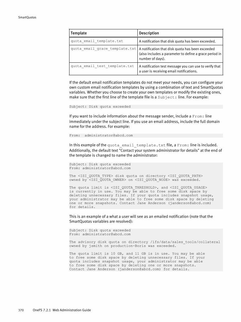
Template Description
quota_email_template.txt A notification that disk quota has been exceeded.
quota_email_grace_template.txt A notification that disk quota has been exceeded(also includes a parameter to define a grace period innumber of days).
quota_email_test_template.txt A notification test message you can use to verify thata user is receiving email notifications.
If the default email notification templates do not meet your needs, you can configure yourown custom email notification templates by using a combination of text and SmartQuotasvariables. Whether you choose to create your own templates or modify the existing ones,make sure that the first line of the template file is a Subject: line. For example:
Subject: Disk quota exceeded
If you want to include information about the message sender, include a From: lineimmediately under the subject line. If you use an email address, include the full domainname for the address. For example:
From: [email protected]
In this example of the quota_email_template.txt file, a From: line is included.Additionally, the default text "Contact your system administrator for details" at the end ofthe template is changed to name the administrator:
Subject: Disk quota exceededFrom: [email protected]
The <ISI_QUOTA_TYPE> disk quota on directory <ISI_QUOTA_PATH> owned by <ISI_QUOTA_OWNER> on <ISI_QUOTA_NODE> was exceeded.
The quota limit is <ISI_QUOTA_THRESHOLD>, and <ISI_QUOTA_USAGE>is currently in use. You may be able to free some disk space by deleting unnecessary files. If your quota includes snapshot usage, your administrator may be able to free some disk space by deleting one or more snapshots. Contact Jane Anderson ([email protected]) for details.
This is an example of a what a user will see as an emailed notification (note that theSmartQuotas variables are resolved):
Subject: Disk quota exceededFrom: [email protected]
The advisory disk quota on directory /ifs/data/sales_tools/collateralowned by jsmith on production-Boris was exceeded.
The quota limit is 10 GB, and 11 GB is in use. You may be able to free some disk space by deleting unnecessary files. If your quota includes snapshot usage, your administrator may be able to free some disk space by deleting one or more snapshots. Contact Jane Anderson ([email protected]) for details.
SmartQuotas
370 OneFS 7.2.1 Web Administration Guide
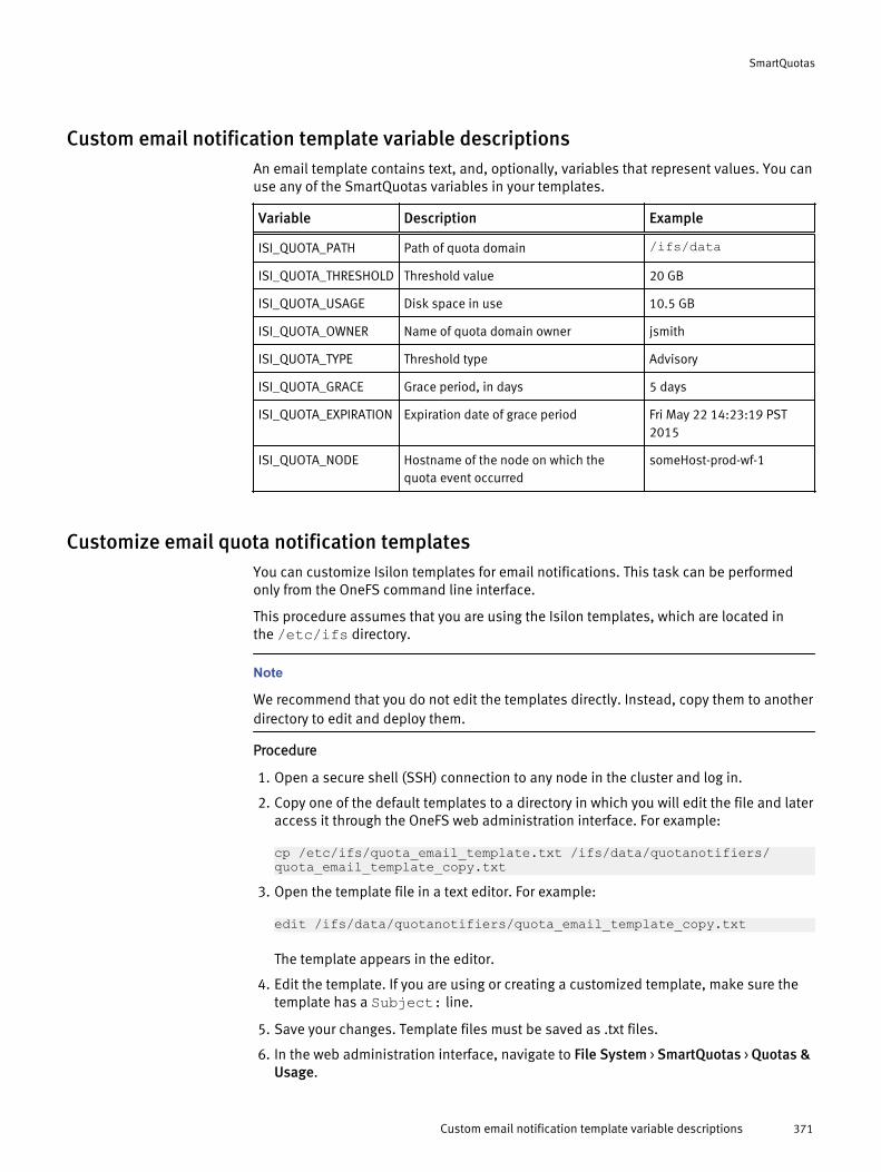
Custom email notification template variable descriptionsAn email template contains text, and, optionally, variables that represent values. You canuse any of the SmartQuotas variables in your templates.
Variable Description Example
ISI_QUOTA_PATH Path of quota domain /ifs/data
ISI_QUOTA_THRESHOLD Threshold value 20 GB
ISI_QUOTA_USAGE Disk space in use 10.5 GB
ISI_QUOTA_OWNER Name of quota domain owner jsmith
ISI_QUOTA_TYPE Threshold type Advisory
ISI_QUOTA_GRACE Grace period, in days 5 days
ISI_QUOTA_EXPIRATION Expiration date of grace period Fri May 22 14:23:19 PST2015
ISI_QUOTA_NODE Hostname of the node on which thequota event occurred
someHost-prod-wf-1
Customize email quota notification templatesYou can customize Isilon templates for email notifications. This task can be performedonly from the OneFS command line interface.
This procedure assumes that you are using the Isilon templates, which are located inthe /etc/ifs directory.
Note
We recommend that you do not edit the templates directly. Instead, copy them to anotherdirectory to edit and deploy them.
Procedure
1. Open a secure shell (SSH) connection to any node in the cluster and log in.
2. Copy one of the default templates to a directory in which you will edit the file and lateraccess it through the OneFS web administration interface. For example:
cp /etc/ifs/quota_email_template.txt /ifs/data/quotanotifiers/quota_email_template_copy.txt
3. Open the template file in a text editor. For example:
edit /ifs/data/quotanotifiers/quota_email_template_copy.txt
The template appears in the editor.
4. Edit the template. If you are using or creating a customized template, make sure thetemplate has a Subject: line.
5. Save your changes. Template files must be saved as .txt files.
6. In the web administration interface, navigate to File System > SmartQuotas > Quotas &Usage.
SmartQuotas
Custom email notification template variable descriptions 371

7. Select the quota that you want to set a notification rule for.
8. Click the Settings tab.
9. Select the notification rule that you want to use with the template that you created (forexample, Advisory Limit Notification Rules). For more information about settingnotification rules, see the instructions for configuring default quota notificationsettings and configuring custom quota notification rules in this chapter.
10. Select the event for the template (for example, Event: Advisory Limit Value Exceeded).
11. In the Send Email area, select one of the owner notification type check boxes.
12. In the Message Template field, enter or browse to find the template that you copied orcustomized.
13. (Optional) In the Event area, select Create Cluster Event to generate an eventnotification in addition to the email notification.
14. (Optional) In the Delay area, select the desired amount of time to wait beforegenerating a notification. The default is zero minutes.
Repeat steps 9 through 14 to specify an email notification template for eachnotification rule you wish to create for the quota.
15. Click Save.
Managing quota reportsYou can configure and schedule reports to help you monitor, track, and analyze storageuse on an Isilon cluster.
You can view and schedule reports and customize report settings to track, monitor, andanalyze disk storage use. Quota reports are managed by configuring settings that giveyou control over when reports are scheduled, how they are generated, where and howmany are stored, and how they are viewed. The maximum number of scheduled reportsthat are available for viewing in the web-administration interface can be configured foreach report type. When the maximum number of reports are stored, the system deletesthe oldest reports to make space for new reports as they are generated.
Create a quota report scheduleYou can configure quota report settings to generate the quota report on a specifiedschedule.
These settings determine whether and when scheduled reports are generated, and whereand how the reports are stored. If you disable a scheduled report, you can still rununscheduled reports at any time.
Procedure
1. Click File System Management > SmartQuotas > Settings.
2. (Optional) On the Quota settings page, for Scheduled Reporting, click On.
The Report Frequency option appears.
3. Click Change schedule, and select the report frequency that you want to set from thelist.
4. Select the reporting schedule options that you want.
5. Click Save.
SmartQuotas
372 OneFS 7.2.1 Web Administration Guide

Results
Reports are generated according to your criteria and can be viewed in the GeneratedReports Archive.
Generate a quota reportIn addition to scheduled quota reports, you can generate a report to capture usagestatistics at a point in time.
Before you begin
Before you can generate a quota report, quotas must exist and no QuotaScan jobs can berunning.
Procedure
1. Click File System Management > SmartQuotas > Generated Reports Archive.
2. In the Generated Quota Reports Archive area, click Generate a quota report.
3. Click Generate Report.
Results
The new report appears in the Quota Reports list.
Locate a quota reportYou can locate quota reports, which are stored as XML files, and use your own tools andtransforms to view them. This task can only be performed from the OneFS command-lineinterface.
Procedure
1. Open a secure shell (SSH) connection to any node in the cluster and log in.
2. Navigate to the directory where quota reports are stored. The following path is thedefault quota report location:
/ifs/.isilon/smartquotas/reports
Note
If quota reports are not in the default directory, you can run the isi quotasettings command to find the directory where they are stored.
3. At the command prompt, run the ls command.
l To view a list of all quota reports in the directory, run the following command:
ls -a *.xmll To view a specific quota report in the directory, run the following command:
ls <filename>.xml
SmartQuotas
Generate a quota report 373
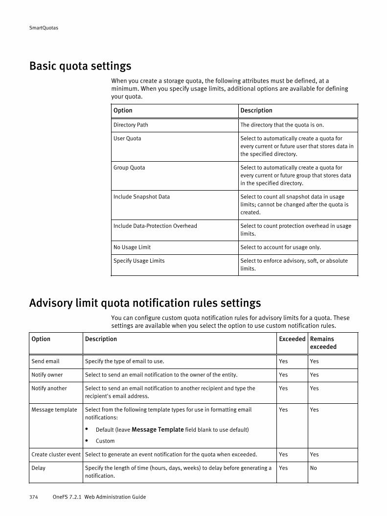
Basic quota settingsWhen you create a storage quota, the following attributes must be defined, at aminimum. When you specify usage limits, additional options are available for definingyour quota.
Option Description
Directory Path The directory that the quota is on.
User Quota Select to automatically create a quota forevery current or future user that stores data inthe specified directory.
Group Quota Select to automatically create a quota forevery current or future group that stores datain the specified directory.
Include Snapshot Data Select to count all snapshot data in usagelimits; cannot be changed after the quota iscreated.
Include Data-Protection Overhead Select to count protection overhead in usagelimits.
No Usage Limit Select to account for usage only.
Specify Usage Limits Select to enforce advisory, soft, or absolutelimits.
Advisory limit quota notification rules settingsYou can configure custom quota notification rules for advisory limits for a quota. Thesesettings are available when you select the option to use custom notification rules.
Option Description Exceeded Remainsexceeded
Send email Specify the type of email to use. Yes Yes
Notify owner Select to send an email notification to the owner of the entity. Yes Yes
Notify another Select to send an email notification to another recipient and type therecipient's email address.
Yes Yes
Message template Select from the following template types for use in formatting emailnotifications:
l Default (leave Message Template field blank to use default)
l Custom
Yes Yes
Create cluster event Select to generate an event notification for the quota when exceeded. Yes Yes
Delay Specify the length of time (hours, days, weeks) to delay before generating anotification.
Yes No
SmartQuotas
374 OneFS 7.2.1 Web Administration Guide
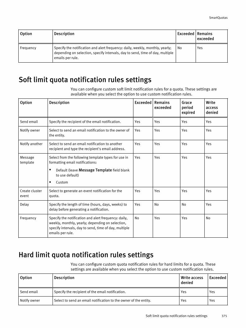
Option Description Exceeded Remainsexceeded
Frequency Specify the notification and alert frequency: daily, weekly, monthly, yearly;depending on selection, specify intervals, day to send, time of day, multipleemails per rule.
No Yes
Soft limit quota notification rules settingsYou can configure custom soft limit notification rules for a quota. These settings areavailable when you select the option to use custom notification rules.
Option Description Exceeded Remainsexceeded
Graceperiodexpired
Writeaccessdenied
Send email Specify the recipient of the email notification. Yes Yes Yes Yes
Notify owner Select to send an email notification to the owner ofthe entity.
Yes Yes Yes Yes
Notify another Select to send an email notification to anotherrecipient and type the recipient's email address.
Yes Yes Yes Yes
Messagetemplate
Select from the following template types for use informatting email notifications:
l Default (leave Message Template field blankto use default)
l Custom
Yes Yes Yes Yes
Create clusterevent
Select to generate an event notification for thequota.
Yes Yes Yes Yes
Delay Specify the length of time (hours, days, weeks) todelay before generating a notification.
Yes No No Yes
Frequency Specify the notification and alert frequency: daily,weekly, monthly, yearly; depending on selection,specify intervals, day to send, time of day, multipleemails per rule.
No Yes Yes No
Hard limit quota notification rules settingsYou can configure custom quota notification rules for hard limits for a quota. Thesesettings are available when you select the option to use custom notification rules.
Option Description Write accessdenied
Exceeded
Send email Specify the recipient of the email notification. Yes Yes
Notify owner Select to send an email notification to the owner of the entity. Yes Yes
SmartQuotas
Soft limit quota notification rules settings 375
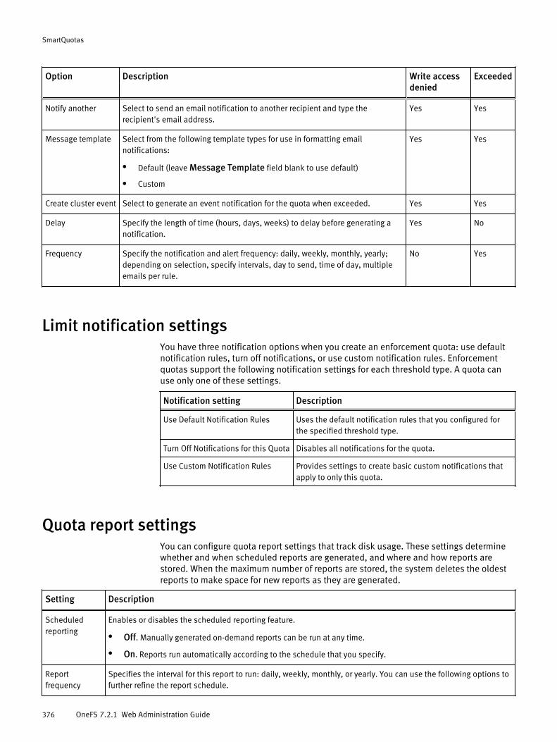
Option Description Write accessdenied
Exceeded
Notify another Select to send an email notification to another recipient and type therecipient's email address.
Yes Yes
Message template Select from the following template types for use in formatting emailnotifications:
l Default (leave Message Template field blank to use default)
l Custom
Yes Yes
Create cluster event Select to generate an event notification for the quota when exceeded. Yes Yes
Delay Specify the length of time (hours, days, weeks) to delay before generating anotification.
Yes No
Frequency Specify the notification and alert frequency: daily, weekly, monthly, yearly;depending on selection, specify intervals, day to send, time of day, multipleemails per rule.
No Yes
Limit notification settingsYou have three notification options when you create an enforcement quota: use defaultnotification rules, turn off notifications, or use custom notification rules. Enforcementquotas support the following notification settings for each threshold type. A quota canuse only one of these settings.
Notification setting Description
Use Default Notification Rules Uses the default notification rules that you configured forthe specified threshold type.
Turn Off Notifications for this Quota Disables all notifications for the quota.
Use Custom Notification Rules Provides settings to create basic custom notifications thatapply to only this quota.
Quota report settingsYou can configure quota report settings that track disk usage. These settings determinewhether and when scheduled reports are generated, and where and how reports arestored. When the maximum number of reports are stored, the system deletes the oldestreports to make space for new reports as they are generated.
Setting Description
Scheduledreporting
Enables or disables the scheduled reporting feature.
l Off. Manually generated on-demand reports can be run at any time.
l On. Reports run automatically according to the schedule that you specify.
Reportfrequency
Specifies the interval for this report to run: daily, weekly, monthly, or yearly. You can use the following options tofurther refine the report schedule.
SmartQuotas
376 OneFS 7.2.1 Web Administration Guide

Setting Description
Generate report every. Specify the numeric value for the selected report frequency; for example, every 2months.
Generate reports on. Select the day or multiple days to generate reports.
Select report day by. Specify date or day of the week to generate the report.
Generate one report per specified by. Set the time of day to generate this report.
Generate multiple reports per specified day. Set the intervals and times of day to generate the report forthat day.
Scheduledreport archiving
Determines the maximum number of scheduled reports that are available for viewing on the SmartQuotas
Reports page.
Limit archive size for scheduled reports to a specified number of reports. Type the integer to specify themaximum number of reports to keep.
Archive Directory. Browse to the directory where you want to store quota reports for archiving.
Manual reportarchiving
Determines the maximum number of manually generated (on-demand) reports that are available for viewing on
the SmartQuotas Reports page.
Limit archive size for live reports to a specified number of reports. Type the integer to specify the maximumnumber of reports to keep.
Archive Directory. Browse to the directory where you want to store quota reports for archiving.
SmartQuotas
Quota report settings 377

SmartQuotas
378 OneFS 7.2.1 Web Administration Guide
CHAPTER 21
Storage Pools
This section contains the following topics:
l Storage pools overview....................................................................................... 380l Storage pool functions........................................................................................ 380l Autoprovisioning.................................................................................................382l Node pools......................................................................................................... 382l Virtual hot spare..................................................................................................385l Spillover..............................................................................................................385l Suggested protection.......................................................................................... 386l Protection policies.............................................................................................. 386l SSD strategies.....................................................................................................387l Global namespace acceleration.......................................................................... 388l L3 cache overview............................................................................................... 388l Tiers....................................................................................................................390l File pool policies................................................................................................. 390l Managing node pools in the web administration interface...................................391l Managing L3 cache from the web administration interface.................................. 396l Managing tiers.................................................................................................... 397l Creating file pool policies....................................................................................399l Managing file pool policies................................................................................. 405l Monitoring storage pools.................................................................................... 410
Storage Pools 379
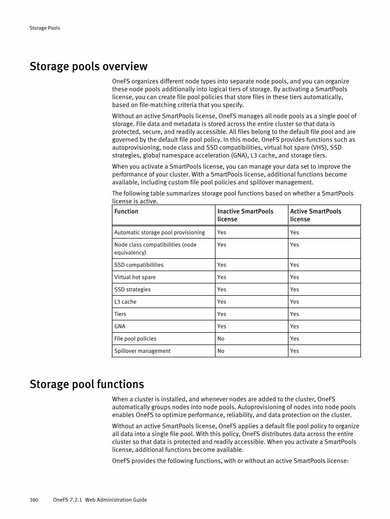
Storage pools overviewOneFS organizes different node types into separate node pools, and you can organizethese node pools additionally into logical tiers of storage. By activating a SmartPoolslicense, you can create file pool policies that store files in these tiers automatically,based on file-matching criteria that you specify.
Without an active SmartPools license, OneFS manages all node pools as a single pool ofstorage. File data and metadata is stored across the entire cluster so that data isprotected, secure, and readily accessible. All files belong to the default file pool and aregoverned by the default file pool policy. In this mode, OneFS provides functions such asautoprovisioning, node class and SSD compatibilities, virtual hot spare (VHS), SSDstrategies, global namespace acceleration (GNA), L3 cache, and storage tiers.
When you activate a SmartPools license, you can manage your data set to improve theperformance of your cluster. With a SmartPools license, additional functions becomeavailable, including custom file pool policies and spillover management.
The following table summarizes storage pool functions based on whether a SmartPoolslicense is active.
Function Inactive SmartPoolslicense
Active SmartPoolslicense
Automatic storage pool provisioning Yes Yes
Node class compatibilities (nodeequivalency)
Yes Yes
SSD compatibilities Yes Yes
Virtual hot spare Yes Yes
SSD strategies Yes Yes
L3 cache Yes Yes
Tiers Yes Yes
GNA Yes Yes
File pool policies No Yes
Spillover management No Yes
Storage pool functionsWhen a cluster is installed, and whenever nodes are added to the cluster, OneFSautomatically groups nodes into node pools. Autoprovisioning of nodes into node poolsenables OneFS to optimize performance, reliability, and data protection on the cluster.
Without an active SmartPools license, OneFS applies a default file pool policy to organizeall data into a single file pool. With this policy, OneFS distributes data across the entirecluster so that data is protected and readily accessible. When you activate a SmartPoolslicense, additional functions become available.
OneFS provides the following functions, with or without an active SmartPools license:
Storage Pools
380 OneFS 7.2.1 Web Administration Guide

Autoprovisioning of node pools
Automatically groups equivalence-class nodes into node pools for optimal storageefficiency and protection. At least three nodes of an equivalence class are requiredfor autoprovisioning to work.
Node class compatibilities (node equivalency)
Enables certain nodes that are not equivalence-class to join existing node pools.OneFS supports node class compatibilities between Isilon S200 and S210 nodes,X200 and X210 nodes, X400 and X410 nodes, and NL400 and NL410 nodes. L3cache must be enabled on the node pools for node class compatibilities to work.
SSD compatibilities
Enables nodes with different SSD capacities to be provisioned to an existingcompatible node pool. Without an SSD compatibility, compatible nodes that havedifferent SSD capacities cannot join the same node pool. If you have fewer thanthree nodes with a difference in SSD capacity, these nodes remain unprovisioned,and, therefore, not functional. L3 cache must be enabled on node pools for SSDcompatibilities to work.
Tiers
Groups node pools into logical tiers of storage. If you activate a SmartPools licensefor this feature, you can create custom file pool policies and direct different filepools to appropriate storage tiers.
Default file pool policy
Governs all file types and can store files anywhere on the cluster. Custom file poolpolicies, which require a SmartPools license, take precedence over the default filepool policy.
Requested protection
Specifies a requested protection setting for the default file pool, per node pool, oreven on individual files. You can leave the default setting in place, or choose thesuggested protection calculated by OneFS for optimal data protection.
Virtual hot spare
Reserves a portion of available storage space for data repair in the event of a diskfailure.
SSD strategies
Defines the type of data that is stored on SSDs in the cluster. For example, storingmetadata for read/write acceleration.
L3 cache
Specifies that SSDs in nodes are used only to cache data and metadata, enablingfaster access to the most frequently requested files.
Global namespace acceleration
Activates global namespace acceleration (GNA), which enables data stored on nodepools without SSDs to access SSDs elsewhere in the cluster to store extra metadatamirrors. Extra metadata mirrors accelerate metadata read operations.
When you activate a SmartPools license, OneFS provides the following additionalfunctions:
Custom file pool policies
Creates custom file pool policies to identify different classes of files, and storesthese file pools in logical storage tiers. For example, you can define a high-
Storage Pools
Storage pool functions 381

performance tier of Isilon S-series node pools and an archival tier of high-capacityIsilon NL400 and HD400 node pools. Then, with custom file pool policies, you canidentify file pools based on matching criteria, and you can define actions to performon these pools. For example, one file pool policy can identify all JPEG files older thana year and store them in an archival tier. Another policy can move all files that werecreated or modified within the last three months to a performance tier.
Storage pool spillover
Enables automated capacity overflow management for storage pools. Spilloverdefines how to handle write operations when a storage pool is not writable. Ifspillover is enabled, data is redirected to a specified storage pool. If spillover isdisabled, new data writes fail and an error message is sent to the client that isattempting the write operation.
AutoprovisioningWhen you add a node to an Isilon cluster, OneFS attempts to assign the node to a nodepool. This process is known as autoprovisioning, which helps OneFS to provide optimalperformance, load balancing, and file system integrity across a cluster.
A node is not autoprovisioned to a node pool and made writable until at least threenodes of the same equivalence class are added to the cluster. If you add only two nodesof an equivalence class, no data is stored on these nodes until a third node of the sameclass is added.
Similarly, if a node goes down or is removed from the cluster so that fewer than threeequivalence-class nodes remain, the node pool becomes under-provisioned. In this case,the two remaining nodes are still writable. However, if only one node of an equivalenceclass remains, this node is not writable, but remains readable.
To work around these restrictions, OneFS offers a node class compatibility function, alsoreferred to as node equivalency. This function enables new node types to be provisionedto existing node pools, even when there are fewer than three of the new nodes. Withnode class compatibilities, you can add nodes one at a time to your cluster, and the newnodes become fully functional peers within a node pool.
For example, an S210 node can be provisioned and added to a node pool of S200 nodes.Similarly, an X410 node can be added to a node pool of X400 nodes.
Node poolsA node pool is a group of three or more Isilon nodes that forms a single pool of storage.As you add nodes to your Isilon cluster, OneFS attempts to automatically provision thenodes into node pools.
To autoprovision a node, OneFS requires that the new node must be of the sameequivalence class as the other nodes in the node pool. OneFS uses the following threecriteria to determine if the new node is of the same equivalence class:
l Family code
l Chassis code
l Generation code
If the new node matches all three criteria, OneFS adds the new node to the node pool. Allnodes in a node pool are peers, and any node can handle a data request. Eachprovisioned node increases the aggregate disk, cache, CPU, and network capacity of thecluster.
Storage Pools
382 OneFS 7.2.1 Web Administration Guide
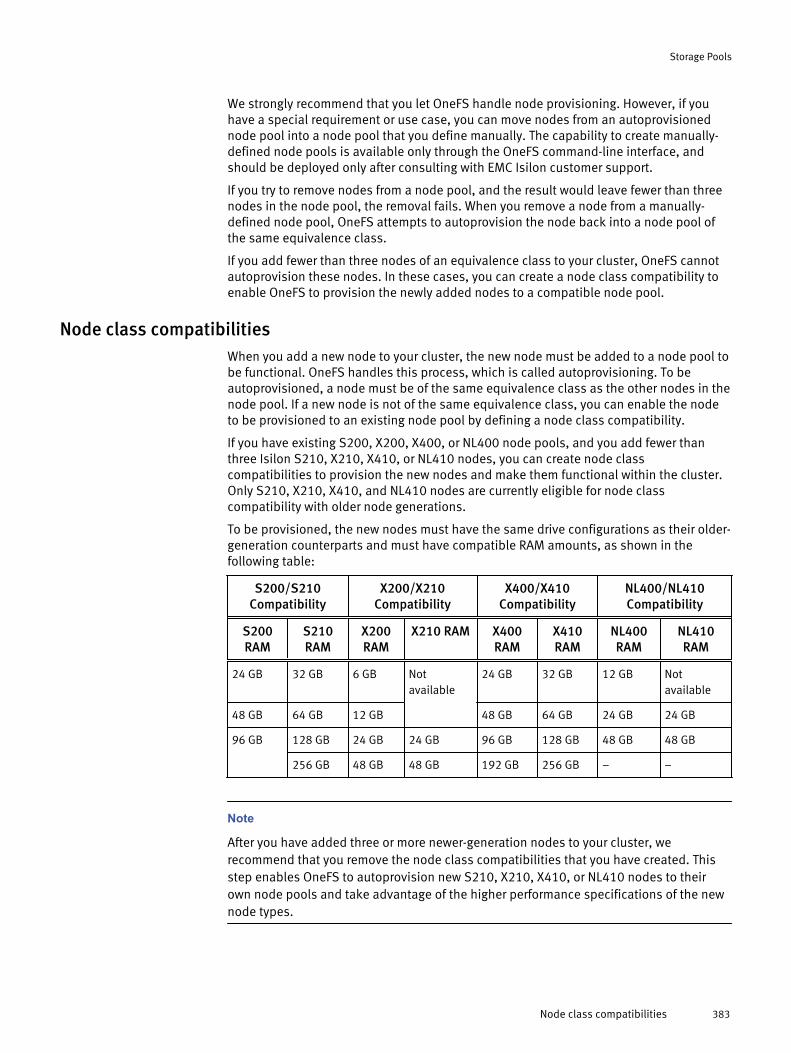
We strongly recommend that you let OneFS handle node provisioning. However, if youhave a special requirement or use case, you can move nodes from an autoprovisionednode pool into a node pool that you define manually. The capability to create manually-defined node pools is available only through the OneFS command-line interface, andshould be deployed only after consulting with EMC Isilon customer support.
If you try to remove nodes from a node pool, and the result would leave fewer than threenodes in the node pool, the removal fails. When you remove a node from a manually-defined node pool, OneFS attempts to autoprovision the node back into a node pool ofthe same equivalence class.
If you add fewer than three nodes of an equivalence class to your cluster, OneFS cannotautoprovision these nodes. In these cases, you can create a node class compatibility toenable OneFS to provision the newly added nodes to a compatible node pool.
Node class compatibilitiesWhen you add a new node to your cluster, the new node must be added to a node pool tobe functional. OneFS handles this process, which is called autoprovisioning. To beautoprovisioned, a node must be of the same equivalence class as the other nodes in thenode pool. If a new node is not of the same equivalence class, you can enable the nodeto be provisioned to an existing node pool by defining a node class compatibility.
If you have existing S200, X200, X400, or NL400 node pools, and you add fewer thanthree Isilon S210, X210, X410, or NL410 nodes, you can create node classcompatibilities to provision the new nodes and make them functional within the cluster.Only S210, X210, X410, and NL410 nodes are currently eligible for node classcompatibility with older node generations.
To be provisioned, the new nodes must have the same drive configurations as their older-generation counterparts and must have compatible RAM amounts, as shown in thefollowing table:
S200/S210Compatibility
X200/X210Compatibility
X400/X410Compatibility
NL400/NL410Compatibility
S200RAM
S210RAM
X200RAM
X210 RAM X400RAM
X410RAM
NL400RAM
NL410RAM
24 GB 32 GB 6 GB Notavailable
24 GB 32 GB 12 GB Notavailable
48 GB 64 GB 12 GB 48 GB 64 GB 24 GB 24 GB
96 GB 128 GB 24 GB 24 GB 96 GB 128 GB 48 GB 48 GB
256 GB 48 GB 48 GB 192 GB 256 GB – –
Note
After you have added three or more newer-generation nodes to your cluster, werecommend that you remove the node class compatibilities that you have created. Thisstep enables OneFS to autoprovision new S210, X210, X410, or NL410 nodes to theirown node pools and take advantage of the higher performance specifications of the newnode types.
Storage Pools
Node class compatibilities 383
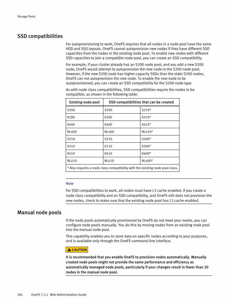
SSD compatibilitiesFor autoprovisioning to work, OneFS requires that all nodes in a node pool have the sameHDD and SSD layouts. OneFS cannot autoprovision new nodes if they have different SSDcapacities from the nodes in the existing node pool. To enable new nodes with differentSSD capacities to join a compatible node pool, you can create an SSD compatibility.
For example, if your cluster already has an S200 node pool, and you add a new S200node, OneFS would attempt to autoprovision the new node to the S200 node pool.However, if the new S200 node has higher-capacity SSDs than the older S200 nodes,OneFS can not autoprovision the new node. To enable the new node to beautoprovisioned, you can create an SSD compatibility for the S200 node type.
As with node class compatibilities, SSD compatibilities require the nodes to becompatible, as shown in the following table:
Existing node pool SSD compatibilities that can be created
S200 S200 S210*
X200 X200 X210*
X400 X400 X410*
NL400 NL400 NL410*
S210 S210 S200*
X210 X210 X200*
X410 X410 X400*
NL410 NL410 NL400*
* Also requires a node class compatibility with the existing node pool class.
Note
For SSD compatibilities to work, all nodes must have L3 cache enabled. If you create anode class compatibility and an SSD compatibility, and OneFS still does not provision thenew nodes, check to make sure that the existing node pool has L3 cache enabled.
Manual node poolsIf the node pools automatically provisioned by OneFS do not meet your needs, you canconfigure node pools manually. You do this by moving nodes from an existing node poolinto the manual node pool.
This capability enables you to store data on specific nodes according to your purposes,and is available only through the OneFS command-line interface.
CAUTION
It is recommended that you enable OneFS to provision nodes automatically. Manuallycreated node pools might not provide the same performance and efficiency asautomatically managed node pools, particularly if your changes result in fewer than 20nodes in the manual node pool.
Storage Pools
384 OneFS 7.2.1 Web Administration Guide

Virtual hot spareVirtual hot spare (VHS) settings enable you to reserve disk space to rebuild the data inthe event that a drive fails.
You can specify both a number of virtual drives to reserve and a percentage of totalstorage space. For example, if you specify two virtual drives and 15 percent, each nodepool reserves virtual drive space equivalent to two drives or 15 percent of their totalcapacity (whichever is larger).
You can reserve space in node pools across the cluster for this purpose by specifying thefollowing options:
l At least 1–4 virtual drives.
l At least 0–20% of total storage.
OneFS calculates the larger number of the two factors to determine the space that isallocated. When configuring VHS settings, be sure to consider the following information:
l If you deselect the option to Ignore reserved space when calculating available freespace (the default), free-space calculations include the space reserved for VHS.
l If you deselect the option to Deny data writes to reserved disk space (the default),OneFS can use VHS for normal data writes. We recommend that you leave this optionselected, or data repair can be compromised.
l If Ignore reserved space when calculating available free space is enabled while Denydata writes to reserved disk space is disabled, it is possible for the file system toreport utilization as more than 100 percent.
Note
VHS settings affect spillover. If the VHS option Deny data writes to reserved disk space isenabled while Ignore reserved space when calculating available free space is disabled,spillover occurs before the file system reports 100% utilization.
SpilloverWhen you activate a SmartPools license, you can designate a node pool or tier to receivespillover data when the hardware specified by a file pool policy is full or otherwise notwritable.
If you do not want data to spill over to a different location because the specified nodepool or tier is full or not writable, you can disable this feature.
Note
Virtual hot spare reservations affect spillover. If the setting Deny data writes to reserveddisk space is enabled, while Ignore reserved space when calculating available free spaceis disabled, spillover occurs before the file system reports 100% utilization.
Storage Pools
Virtual hot spare 385
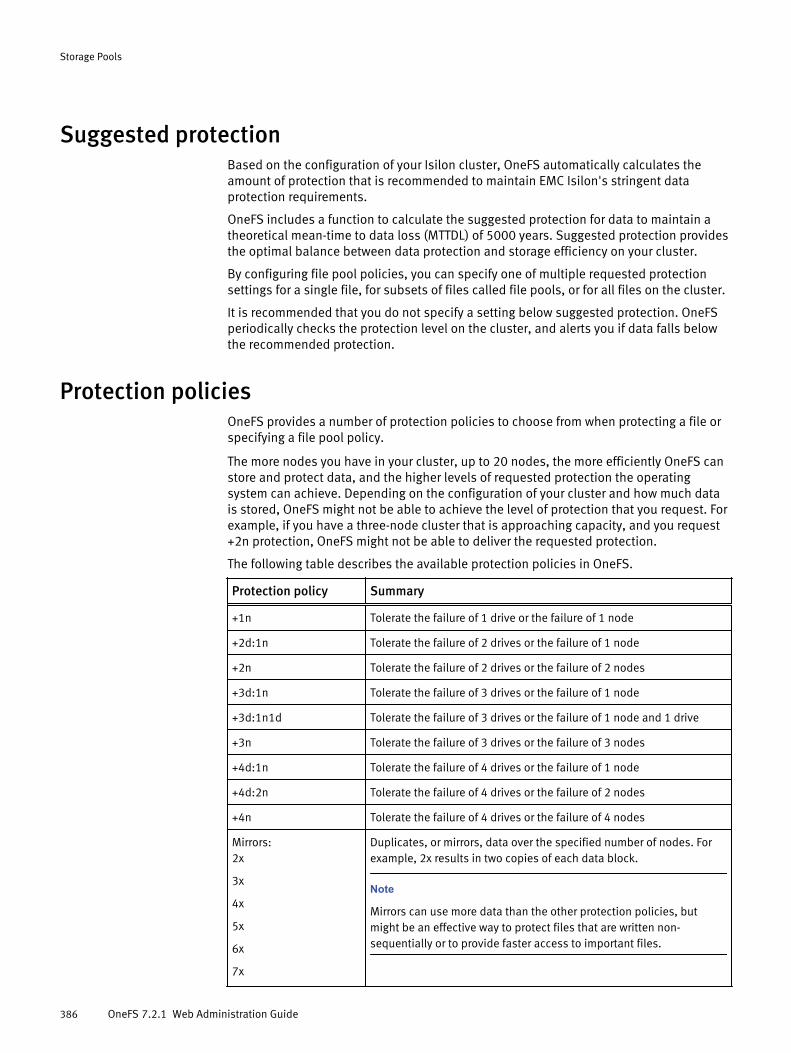
Suggested protectionBased on the configuration of your Isilon cluster, OneFS automatically calculates theamount of protection that is recommended to maintain EMC Isilon's stringent dataprotection requirements.
OneFS includes a function to calculate the suggested protection for data to maintain atheoretical mean-time to data loss (MTTDL) of 5000 years. Suggested protection providesthe optimal balance between data protection and storage efficiency on your cluster.
By configuring file pool policies, you can specify one of multiple requested protectionsettings for a single file, for subsets of files called file pools, or for all files on the cluster.
It is recommended that you do not specify a setting below suggested protection. OneFSperiodically checks the protection level on the cluster, and alerts you if data falls belowthe recommended protection.
Protection policiesOneFS provides a number of protection policies to choose from when protecting a file orspecifying a file pool policy.
The more nodes you have in your cluster, up to 20 nodes, the more efficiently OneFS canstore and protect data, and the higher levels of requested protection the operatingsystem can achieve. Depending on the configuration of your cluster and how much datais stored, OneFS might not be able to achieve the level of protection that you request. Forexample, if you have a three-node cluster that is approaching capacity, and you request+2n protection, OneFS might not be able to deliver the requested protection.
The following table describes the available protection policies in OneFS.
Protection policy Summary
+1n Tolerate the failure of 1 drive or the failure of 1 node
+2d:1n Tolerate the failure of 2 drives or the failure of 1 node
+2n Tolerate the failure of 2 drives or the failure of 2 nodes
+3d:1n Tolerate the failure of 3 drives or the failure of 1 node
+3d:1n1d Tolerate the failure of 3 drives or the failure of 1 node and 1 drive
+3n Tolerate the failure of 3 drives or the failure of 3 nodes
+4d:1n Tolerate the failure of 4 drives or the failure of 1 node
+4d:2n Tolerate the failure of 4 drives or the failure of 2 nodes
+4n Tolerate the failure of 4 drives or the failure of 4 nodes
Mirrors:2x
3x
4x
5x
6x
7x
Duplicates, or mirrors, data over the specified number of nodes. Forexample, 2x results in two copies of each data block.
Note
Mirrors can use more data than the other protection policies, butmight be an effective way to protect files that are written non-sequentially or to provide faster access to important files.
Storage Pools
386 OneFS 7.2.1 Web Administration Guide
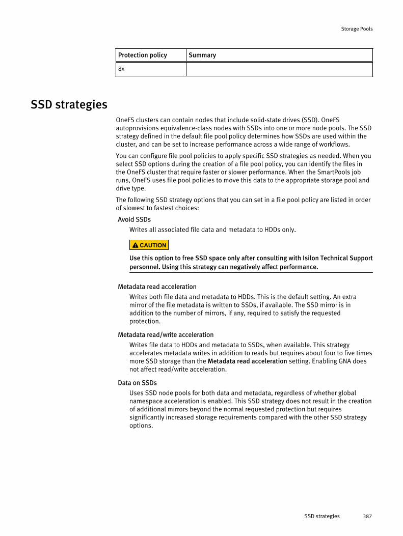
Protection policy Summary
8x
SSD strategiesOneFS clusters can contain nodes that include solid-state drives (SSD). OneFSautoprovisions equivalence-class nodes with SSDs into one or more node pools. The SSDstrategy defined in the default file pool policy determines how SSDs are used within thecluster, and can be set to increase performance across a wide range of workflows.
You can configure file pool policies to apply specific SSD strategies as needed. When youselect SSD options during the creation of a file pool policy, you can identify the files inthe OneFS cluster that require faster or slower performance. When the SmartPools jobruns, OneFS uses file pool policies to move this data to the appropriate storage pool anddrive type.
The following SSD strategy options that you can set in a file pool policy are listed in orderof slowest to fastest choices:
Avoid SSDs
Writes all associated file data and metadata to HDDs only.
CAUTION
Use this option to free SSD space only after consulting with Isilon Technical Supportpersonnel. Using this strategy can negatively affect performance.
Metadata read acceleration
Writes both file data and metadata to HDDs. This is the default setting. An extramirror of the file metadata is written to SSDs, if available. The SSD mirror is inaddition to the number of mirrors, if any, required to satisfy the requestedprotection.
Metadata read/write acceleration
Writes file data to HDDs and metadata to SSDs, when available. This strategyaccelerates metadata writes in addition to reads but requires about four to five timesmore SSD storage than the Metadata read acceleration setting. Enabling GNA doesnot affect read/write acceleration.
Data on SSDs
Uses SSD node pools for both data and metadata, regardless of whether globalnamespace acceleration is enabled. This SSD strategy does not result in the creationof additional mirrors beyond the normal requested protection but requiressignificantly increased storage requirements compared with the other SSD strategyoptions.
Storage Pools
SSD strategies 387
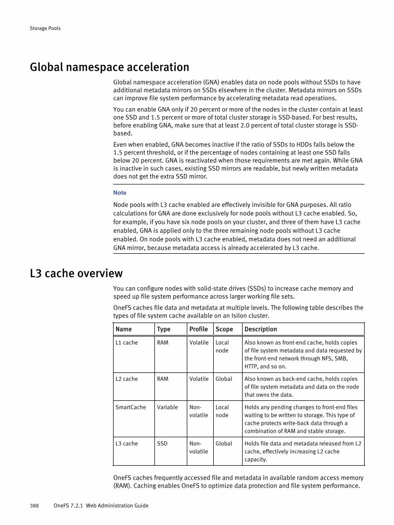
Global namespace accelerationGlobal namespace acceleration (GNA) enables data on node pools without SSDs to haveadditional metadata mirrors on SSDs elsewhere in the cluster. Metadata mirrors on SSDscan improve file system performance by accelerating metadata read operations.
You can enable GNA only if 20 percent or more of the nodes in the cluster contain at leastone SSD and 1.5 percent or more of total cluster storage is SSD-based. For best results,before enabling GNA, make sure that at least 2.0 percent of total cluster storage is SSD-based.
Even when enabled, GNA becomes inactive if the ratio of SSDs to HDDs falls below the1.5 percent threshold, or if the percentage of nodes containing at least one SSD fallsbelow 20 percent. GNA is reactivated when those requirements are met again. While GNAis inactive in such cases, existing SSD mirrors are readable, but newly written metadatadoes not get the extra SSD mirror.
Note
Node pools with L3 cache enabled are effectively invisible for GNA purposes. All ratiocalculations for GNA are done exclusively for node pools without L3 cache enabled. So,for example, if you have six node pools on your cluster, and three of them have L3 cacheenabled, GNA is applied only to the three remaining node pools without L3 cacheenabled. On node pools with L3 cache enabled, metadata does not need an additionalGNA mirror, because metadata access is already accelerated by L3 cache.
L3 cache overviewYou can configure nodes with solid-state drives (SSDs) to increase cache memory andspeed up file system performance across larger working file sets.
OneFS caches file data and metadata at multiple levels. The following table describes thetypes of file system cache available on an Isilon cluster.
Name Type Profile Scope Description
L1 cache RAM Volatile Localnode
Also known as front-end cache, holds copiesof file system metadata and data requested bythe front-end network through NFS, SMB,HTTP, and so on.
L2 cache RAM Volatile Global Also known as back-end cache, holds copiesof file system metadata and data on the nodethat owns the data.
SmartCache Variable Non-volatile
Localnode
Holds any pending changes to front-end fileswaiting to be written to storage. This type ofcache protects write-back data through acombination of RAM and stable storage.
L3 cache SSD Non-volatile
Global Holds file data and metadata released from L2cache, effectively increasing L2 cachecapacity.
OneFS caches frequently accessed file and metadata in available random access memory(RAM). Caching enables OneFS to optimize data protection and file system performance.
Storage Pools
388 OneFS 7.2.1 Web Administration Guide
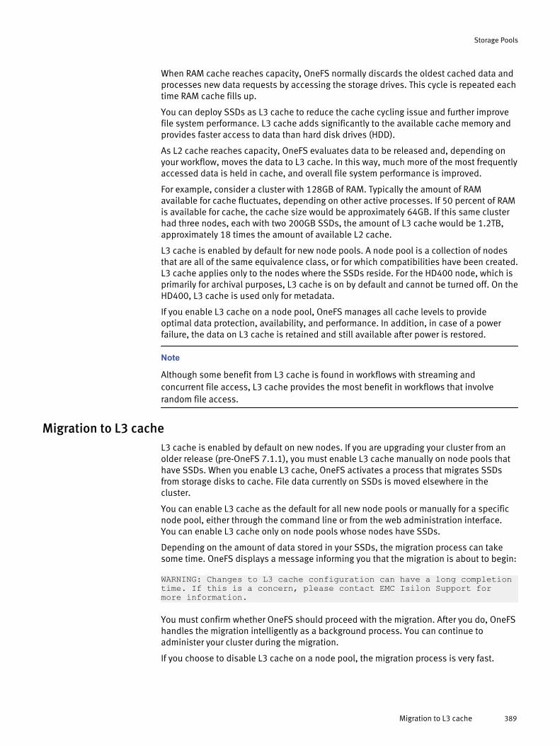
When RAM cache reaches capacity, OneFS normally discards the oldest cached data andprocesses new data requests by accessing the storage drives. This cycle is repeated eachtime RAM cache fills up.
You can deploy SSDs as L3 cache to reduce the cache cycling issue and further improvefile system performance. L3 cache adds significantly to the available cache memory andprovides faster access to data than hard disk drives (HDD).
As L2 cache reaches capacity, OneFS evaluates data to be released and, depending onyour workflow, moves the data to L3 cache. In this way, much more of the most frequentlyaccessed data is held in cache, and overall file system performance is improved.
For example, consider a cluster with 128GB of RAM. Typically the amount of RAMavailable for cache fluctuates, depending on other active processes. If 50 percent of RAMis available for cache, the cache size would be approximately 64GB. If this same clusterhad three nodes, each with two 200GB SSDs, the amount of L3 cache would be 1.2TB,approximately 18 times the amount of available L2 cache.
L3 cache is enabled by default for new node pools. A node pool is a collection of nodesthat are all of the same equivalence class, or for which compatibilities have been created.L3 cache applies only to the nodes where the SSDs reside. For the HD400 node, which isprimarily for archival purposes, L3 cache is on by default and cannot be turned off. On theHD400, L3 cache is used only for metadata.
If you enable L3 cache on a node pool, OneFS manages all cache levels to provideoptimal data protection, availability, and performance. In addition, in case of a powerfailure, the data on L3 cache is retained and still available after power is restored.
Note
Although some benefit from L3 cache is found in workflows with streaming andconcurrent file access, L3 cache provides the most benefit in workflows that involverandom file access.
Migration to L3 cacheL3 cache is enabled by default on new nodes. If you are upgrading your cluster from anolder release (pre-OneFS 7.1.1), you must enable L3 cache manually on node pools thathave SSDs. When you enable L3 cache, OneFS activates a process that migrates SSDsfrom storage disks to cache. File data currently on SSDs is moved elsewhere in thecluster.
You can enable L3 cache as the default for all new node pools or manually for a specificnode pool, either through the command line or from the web administration interface.You can enable L3 cache only on node pools whose nodes have SSDs.
Depending on the amount of data stored in your SSDs, the migration process can takesome time. OneFS displays a message informing you that the migration is about to begin:
WARNING: Changes to L3 cache configuration can have a long completion time. If this is a concern, please contact EMC Isilon Support for more information.
You must confirm whether OneFS should proceed with the migration. After you do, OneFShandles the migration intelligently as a background process. You can continue toadminister your cluster during the migration.
If you choose to disable L3 cache on a node pool, the migration process is very fast.
Storage Pools
Migration to L3 cache 389
L3 cache on NL-series and HD-series node poolsThe HD-series and NL-series nodes are high-capacity units designed primarily for archivalworkflows. Archival workflows feature a higher percentage of data writes compared todata reads, and L3 cache with SSDs can improve significantly the speed of file systemtraversal activities such as directory lookup.
L3 cache is turned on by default on HD-series and NL-series node pools.
For NL-series nodes with hard-disk drives (HDD) smaller than 4 TB in capacity, L3 cachestores both data and metadata in SSDs by default. You can turn off L3 cache on NL-seriesnodes with 4 TB or smaller HDDs. However, we recommend that you leave L3 cacheenabled, as NL-series nodes typically do not have large numbers of SSDs. From aperformance perspective, the benefits of L3 cache outweigh the benefits of using SSDs asstorage drives on these nodes.
For NL-series nodes with HDDs greater than 4 TB in capacity, and for all HD-series nodes,L3 cache stores metadata only in SSDs and cannot be disabled. L3 cache with metadataonly stored in SSDs provides the best performance for archiving data on these high-capacity nodes.
TiersA tier is a user-defined collection of node pools that you can specify as a storage pool forfiles. A node pool can belong to only one tier.
You can create tiers to assign your data to any of the node pools in the tier. For example,you can assign a collection of node pools to a tier specifically created to store data thatrequires high availability and fast access. In a three-tier system, this classification maybe Tier 1. You can classify data that is used less frequently or that is accessed by fewerusers as Tier-2 data. Tier 3 usually comprises data that is seldom used and can bearchived for historical or regulatory purposes.
File pool policiesFile pool policies define sets of files—file pools—and where and how they are stored onyour cluster. You can configure multiple file pool policies with filtering rules that identifyspecific file pools and the requested protection and I/O optimization settings for thesefile pools. Creating custom file pool policies requires an active SmartPools license.
The initial installation of OneFS places all files into a single file pool, which is subject tothe default file pool policy. Without an active SmartPools license, you can configure onlythe default file pool policy, which controls all files and stores them anywhere on thecluster.
With an active SmartPools license, OneFS augments basic storage functions by enablingyou to create custom file pool policies that identify, protect, and control multiple filepools. With a custom file pool policy, for example, you can define and store a file pool ona specific node pool or tier for fast access or archival purposes.
When you create a file pool policy, flexible filtering criteria enable you to specify time-based attributes for the dates that files were last accessed, modified, or created. You canalso define relative time attributes, such as 30 days before the current date. Otherfiltering criteria include file type, name, size, and custom attributes. The followingexamples demonstrate a few ways you can configure file pool policies:
l A file pool policy to set stronger protection on a specific set of important files.
Storage Pools
390 OneFS 7.2.1 Web Administration Guide
l A file pool policy to store frequently accessed files in a node pool that provides thefastest reads or read/writes.
l A file pool policy to evaluate the last time files were accessed, so that older files arestored in a node pool best suited for regulatory archival purposes.
When the SmartPools job runs, typically once a day, it processes file pool policies inpriority order. You can edit, reorder, or remove custom file pool policies at any time. Thedefault file pool policy, however, is always last in priority order. Although you can edit thedefault file pool policy, you cannot reorder or remove it. When custom file pool policiesare in place, the settings in the default file pool policy apply only to files that are notcovered by another file pool policy.
When a new file is created, OneFS chooses a storage pool based on the default file poolpolicy, or, if it exists, a higher-priority custom file pool policy that matches the file. If anew file was originally matched by the default file pool policy, and you later create acustom file pool policy that matches the file, the file will be controlled by the new custompolicy. As a result, the file could be placed in a different storage pool the next time theSmartPools job runs.
Managing node pools in the web administration interfaceYou can manage node pools through the OneFS web administration interface. You musthave the SmartPools or higher administrative privilege.
Add node pools to a tierYou can group available node pools into tiers.
A node pool can only be added to one tier at a time. If no node pools are listed asavailable, they already belong to other tiers.
Procedure
1. Click File System > Storage Pools > SmartPools.
The SmartPools page displays two groups: Tiers & Node Pools and Compatibilities
2. In the Tiers & Node Pools area, click View/Edit next to the tier.
3. In the View Tier Details page, click Edit Tier.
The Edit Tier Details page is displayed.
4. In the Available Node Pools list, select a node pool and click Add.
The node pool moves to the Selected Node Pools for this Tier list.
5. Repeat step 4 for each node pool you intend to add. When all node pools have beenadded, click Save Changes.
A message informs you that the operation was successful. The View Tier Details pageremains open.
6. Click Close.
The Tiers & Node Pools group now shows that the node pools are part of the tier.
Storage Pools
Managing node pools in the web administration interface 391

Change the name or requested protection of a node poolYou can change the name or the requested protection of a node pool.
Procedure
1. Click File System > Storage Pools > SmartPools.
2. In the Tiers & Node Pools group, in the row of the node pool that you want to modify,click View/Edit.
The View Node Pools Details page appears.
3. Click Edit.
The Edit Node Pools Details page appears.
4. Enter a new name for the node pool, or specify a new requested protection level fromthe list, or do both.
A node pool name can start only with a letter or underscore character, and otherwisecan contain only letters, numbers, hyphens, underscores, or periods.
5. Click Save Changes in the Edit Node Pools Details page.
6. Click Close in the View Node Pools Details page.
Create a node class compatibilityOneFS automatically adds a new equivalence-class node to an existing node pool. Fornew nodes that are not equivalence-class, you can create a node class compatibility toadd these nodes to an existing node pool.
The following compatibilities are currently supported: S200/S210, X200/X210, X400/X410, and NL400/NL410. For example, if you have a node pool made up of three or moreS200 nodes, you can create a compatibility so that new S210 nodes are automaticallyadded to the S200 node pool.
Note
New nodes must have compatible RAM and the same drive configurations as their oldercounterparts to be provisioned into those node pools.
Procedure
1. Select File System > Storage Pools > SmartPools.
The SmartPools tab displays two lists: Tiers & Node Pools and Compatibilities.
2. Click Create a Node Class Compatibility.
The Create a Compatibility dialog box displays drop-down lists of compatibilityoptions.
3. In the Make list, select a node type.
4. In the compatible with list, select a node type.
5. Click Create a Compatibility.
A Confirm Changes to this Cluster dialog box appears, with two check boxes that youmust select before proceeding. The check boxes describe the result of the operation.
6. Select all check boxes, and then click Confirm.
Storage Pools
392 OneFS 7.2.1 Web Administration Guide

Results
The node class compatibility is created, and is also described in the Compatibilities list.The result of the new compatibility appears in the Tiers & Node Pools list. For example, amessage such as "The S200 Node Class is now considered compatible with the S210Node Class" is displayed. If the new nodes are node-class compatible, but remainunprovisioned, you still need to create an SSD compatibility for the new nodes. If L3cache is disabled on the targeted node pool, the new nodes remain unprovisioned, andan error message is generated.
Merge compatible node poolsYou can create a node class compatibility to merge multiple compatible node pools.Larger node pools, up to 20 nodes, enable OneFS to protect data more efficiently,therefore providing more storage space for new data.
For example, if you have six S200 nodes in one node pool and three S210 nodes in asecond node pool, you can create a compatibility to merge the two node pools into onenine-node pool.
Note
Newer node types typically have better performance specifications than older node types,so merging them with older node types can reduce performance. Also, when two nodepools are merged, OneFS restripes the data, which can take considerable time,depending on the size of your data set.
Procedure
1. Click File System > Storage Pools > SmartPools.
The SmartPools tab displays two lists: Tiers & Node Pools and Compatibilities.
2. Click Create a Node Class Compatibility.
The Create a Compatibility dialog box displays drop-down lists of compatibilityoptions.
3. In the Make list, select a node type.
4. In the compatible with list, select a node type.
5. Click Create a Compatibility.
A Confirm Changes to this Cluster dialog box appears with two check boxes that youmust select before proceeding. The check boxes describe the result of the operation.
6. Click Confirm.
Results
The node class compatibility is created, and is also described in the Compatibilities list.The result of the new compatibility appears in the Tiers & Node Pools list. For example, amessage such as "The S200 Node Class is now considered compatible with the S210Node Class" is displayed. If the node pools do not merge, either L3 cache is disabled onone or both of the node pools, or you still need to create an SSD compatibility betweenthe two node pools.
Storage Pools
Merge compatible node pools 393

Delete a node class compatibilityYou can delete a node class compatibility. As a result, any nodes that were provisioned toa node pool because of this compatibility are removed from the node pool.
CAUTION
Deleting a node class compatibility could result in unintended consequences. Forexample, if you delete a compatibility, and fewer than three compatible nodes areremoved from the node pool, those nodes will be removed from your cluster's availablepool of storage. The next time the SmartPools job runs, data on those nodes would berestriped elsewhere on the cluster, which could be a time-consuming process. If three ormore compatible nodes are removed from the node pool, these nodes will form their ownnode pool, and data will be restriped. Any file pool policy pointing to the original nodepool will now point to the node pool's tier, if one existed, or, otherwise, to a new tiercreated by OneFS.
Procedure
1. Click File System > Storage Pools > SmartPools.
The SmartPools tab displays two lists: Tiers & Node Pools and Compatibilities.
2. In the Compatibilities list, next to the compatibility that you want to delete, clickDelete.
The Delete a Compatibility dialog box appears, describing the compatibility that youare about to delete.
3. Click Delete Compatibility.
A Confirm Changes to this Cluster dialog box appears with check boxes that you mustselect before proceeding.
4. Select all check boxes in the dialog box, and click Confirm.
Results
The compatibility is deleted, and the new state of the affected nodes appears in the Tiers& Node Pools list.
Create an SSD compatibilityAn SSD compatibility can enable nodes with SSDs to be provisioned to a node poolwhose nodes have lower-capacity or higher-capacity SSDs.
For example, if you have a node pool made up of three S200 nodes, and you add an S200node with a higher SSD capacity to your cluster, you can create an SSD compatibility sothat new S200 node could be provisioned to the S200 node pool. SSD compatibilitiescan be created for the following node types: S200, S210, X200, X210, X400, X410,NL400, and NL410.
Procedure
1. Select File System > Storage Pools > SmartPools.
The SmartPools tab displays two lists: Tiers & Node Pools and Compatibilities.
2. Click Create an SSD Compatibility.
The Create a Compatibility dialog box displays a drop-down list of available SSDcompatibilities.
Storage Pools
394 OneFS 7.2.1 Web Administration Guide
3. From the Available SSD Compatibilities list, select the appropriate node type.
For example, if you select S200, all S200 nodes, regardless of their SSD capacities,become compatible and can be provisioned to the same node pool.
4. Click Create an SSD Compatibility.
A Confirm Changes to this Cluster dialog box appears with one or more check boxesthat you must select before proceeding. The check boxes describe the result of theoperation.
5. Select all check boxes, then click Confirm.
Results
The SSD compatibility is created and is also described in the Compatibilities list. Theresult of the SSD compatibility appears in the Tiers & Node Pools list. For example, amessage such as "S200 and S210 nodes are SSD compatible" is displayed. If L3 cache isturned off on any node pools that would be affected by the SSD compatibility, the SSDcompatibility is not created, and an error message is generated. To correct the situation,turn on L3 cache for those node pools.
Delete an SSD compatibilityYou can delete an SSD compatibility, which can cause provisioned nodes to becomeunprovisioned from a node pool.
CAUTION
Deleting an SSD compatibility could result in unintended consequences. For example, ifyou delete an SSD compatibility, and fewer than three compatible nodes are removedfrom a node pool as a result, these nodes will be removed from your cluster's availablepool of storage. The next time the SmartPools job runs, data on those nodes will berestriped elsewhere on the cluster, which could be a time-consuming process. If three ormore compatible nodes are removed from the node pool, these nodes will form their ownnode pool, but data will still be restriped. Any file pool policy pointing to the originalnode pool will now point to the node pool's tier, if one existed, or, otherwise, to a newtier created by OneFS.
Procedure
1. Click File System > Storage Pools > SmartPools.
The SmartPools tab displays two lists: Tiers & Node Pools and Compatibilities.
2. In the Compatibilities list, next to the SSD compatibility that you want to delete, clickDelete.
The Delete an SSD Compatibility dialog box appears, describing the compatibility thatyou are about to delete.
3. Click Delete SSD Compatibility.
A Confirm Changes to this Cluster dialog box appears with one or more check boxesthat you must select before proceeding. The check boxes describe the result of theoperation.
4. Select all check boxes in the dialog box, and click Confirm.
Storage Pools
Delete an SSD compatibility 395
Results
The SSD compatibility is deleted, and the new state of the affected nodes appears in theTiers & Node Pools list. For example, a previously unprovisioned node is nowprovisioned, or two separate node pools are merged into one node pool.
Managing L3 cache from the web administration interfaceYou can manage L3 cache globally or on specific node pools from the web administrationinterface. You must have the SmartPools or higher administrative privilege. On HD400nodes, L3 cache is turned on by default and cannot be turned off.
Set L3 cache as the default for node poolsYou can set L3 cache as the default, so that when new node pools are created, L3 cacheis enabled automatically.
Before you begin
L3 cache is only effective on nodes that include SSDs. If none of your clusters have SSDstorage, there is no need to enable L3 cache as the default.
Procedure
1. Click File System > Storage Pools > SmartPools Settings.
The Edit SmartPools Settings page appears.
2. Under Local Storage Settings, click Use SSDs as L3 Cache by default for new nodepools.
3. Click Save Changes.
Results
As you add new nodes with SSDs to your cluster, and OneFS designates new node pools,these node pools automatically have L3 cache enabled. New node pools without SSDs donot have L3 cache enabled by default.
Set L3 cache on a specific node poolYou can turn on L3 cache for a specific node pool.
Procedure
1. Click File System > Storage Pools > SmartPools.
The SmartPools page, showing a list of tiers and node pools, appears.
2. In the Tiers & Node Pools list, click View/Edit next to the target node pool.
The View Node Pool Details dialog box appears, showing the current settings of thenode pool.
3. Click Edit.
The Edit Node Pool Details dialog box appears.
4. Click the Enable L3 cache check box.
The check box is grayed out for node pools that do not have SSDs, or for which thesetting cannot be changed.
5. Click Save Changes.
The Confirm Change to L3 Cache Setting message box appears.
Storage Pools
396 OneFS 7.2.1 Web Administration Guide
6. Click the Continue button.
The migration process to L3 cache begins and can take awhile, depending on thenumber and size of the SSDs in the node pool. When the migration process iscomplete, the View Node Pool Details dialog box appears.
7. Click Close.
Restore SSDs to storage drives for a node poolYou can disable L3 cache for SSDs on a node pool and restore those SSDs to storagedrives.
Note
On HD400 node pools, SSDs are only used for L3 cache, which is turned on by defaultand cannot be turned off. All other node pools with SSDs for L3 cache can have theirSSDs migrated back to storage drives.
Procedure
1. Click File System > Storage Pools > SmartPools.
2. In the Tiers & Node Pools area of the SmartPools tab, select View/Edit next to thetarget node pool.
The View Node Pool Details dialog box appears, showing the current settings of thenode pool.
3. Click Edit.
The Edit Node Pool Details dialog box appears.
4. Clear the Enable L3 cache check box.
The setting is grayed out for node pools without SSDs, or for which the setting cannotbe changed.
5. Click Save Changes.
The Confirm Change to L3 Cache Setting message box appears.
6. Click Continue.
The migration process to disable L3 cache begins and can take awhile, depending onthe number and size of the SSDs in the node pool. When the migration process iscomplete, the View Node Pool Details dialog box appears.
7. Click Close.
Managing tiersYou can move node pools into tiers to optimize file and storage management. Managingtiers requires the SmartPools or higher administrative privilege.
Create a tierYou can group create a tier that contains one or more node pools. You can use the tier tostore specific categories of files.
Procedure
1. Click File System > Storage Pools > SmartPools.
Storage Pools
Restore SSDs to storage drives for a node pool 397
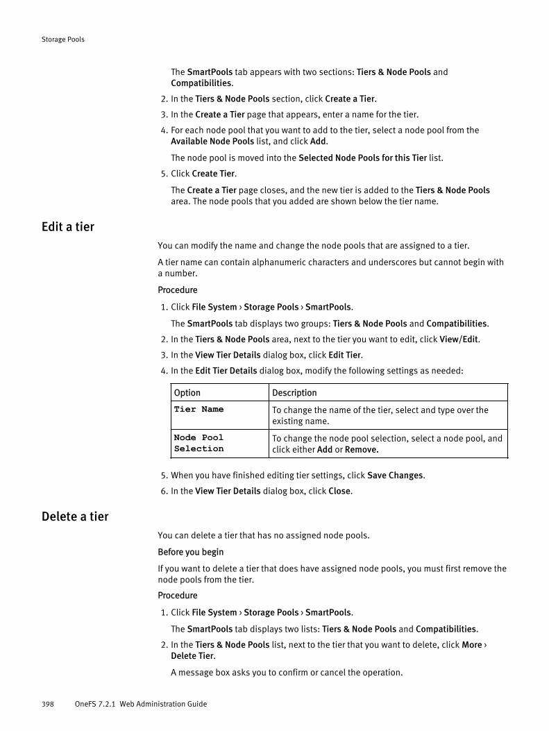
The SmartPools tab appears with two sections: Tiers & Node Pools andCompatibilities.
2. In the Tiers & Node Pools section, click Create a Tier.
3. In the Create a Tier page that appears, enter a name for the tier.
4. For each node pool that you want to add to the tier, select a node pool from theAvailable Node Pools list, and click Add.
The node pool is moved into the Selected Node Pools for this Tier list.
5. Click Create Tier.
The Create a Tier page closes, and the new tier is added to the Tiers & Node Poolsarea. The node pools that you added are shown below the tier name.
Edit a tierYou can modify the name and change the node pools that are assigned to a tier.
A tier name can contain alphanumeric characters and underscores but cannot begin witha number.
Procedure
1. Click File System > Storage Pools > SmartPools.
The SmartPools tab displays two groups: Tiers & Node Pools and Compatibilities.
2. In the Tiers & Node Pools area, next to the tier you want to edit, click View/Edit.
3. In the View Tier Details dialog box, click Edit Tier.
4. In the Edit Tier Details dialog box, modify the following settings as needed:
Option Description
Tier Name To change the name of the tier, select and type over theexisting name.
Node PoolSelection
To change the node pool selection, select a node pool, andclick either Add or Remove.
5. When you have finished editing tier settings, click Save Changes.
6. In the View Tier Details dialog box, click Close.
Delete a tierYou can delete a tier that has no assigned node pools.
Before you begin
If you want to delete a tier that does have assigned node pools, you must first remove thenode pools from the tier.
Procedure
1. Click File System > Storage Pools > SmartPools.
The SmartPools tab displays two lists: Tiers & Node Pools and Compatibilities.
2. In the Tiers & Node Pools list, next to the tier that you want to delete, click More >Delete Tier.
A message box asks you to confirm or cancel the operation.
Storage Pools
398 OneFS 7.2.1 Web Administration Guide
3. Click Delete Tier to confirm the operation.
Results
The tier is removed from the Tiers & Node Pools list.
Creating file pool policiesYou can configure file pool policies to identify logical groups of files called file pools, andyou can specify storage operations for these files.
Before you can create file pool policies, you must activate a SmartPools license, and youmust have the SmartPools or higher administrative privilege.
File pool policies have two parts: file-matching criteria that define a file pool, and theactions to be applied to the file pool. You can define file pools based on characteristics,such as file type, size, path, birth, change, and access timestamps, and combine thesecriteria with Boolean operators (AND, OR).
In addition to file-matching criteria, you can identify a variety of actions to apply to thefile pool. These actions include:
l Setting requested protection and data-access optimization parameters
l Identifying data and snapshot storage targets
l Defining data and snapshot SSD strategies
l Enabling or disabling SmartCache
For example, to free up disk space on your performance tier (S-series node pools), youcould create a file pool policy to match all files greater than 25 MB in size, which have notbeen accessed or modified for more than a month, and move them to your archive tier(NL-series node pools).
You can configure and prioritize multiple file pool policies to optimize file storage for yourparticular work flows and cluster configuration. When the SmartPools job runs, by defaultonce a day, it applies file pool policies in priority order. When a file pool matches thecriteria defined in a policy, the actions in that policy are applied, and lower-prioritycustom policies are ignored for the file pool.
After the list of custom file pool policies is traversed, if any of the actions are not appliedto a file, the actions in the default file pool policy are applied. In this way, the default filepool policy ensures that all actions apply to every file.
Note
You can reorder the file pool policy list at any time, but the default file pool policy isalways last in the list of file pool policies.
OneFS also provides customizable template policies that you can copy to make your ownpolicies. These templates, however, are only available from the OneFS webadministration interface.
Create a file pool policyYou can create a file pool policy to define a specific file set and specify SmartPoolsactions to be applied to the matched files. These SmartPools actions include moving files
Storage Pools
Creating file pool policies 399

to certain tiers or node pools, changing the requested protection levels, and optimizingwrite performance and data access.
CAUTION
If existing file pool policies direct data to a specific storage pool, do not configure otherfile pool policies with anywhere for the Data storage target option. Because thespecified storage pool is included when you use anywhere, target specific storagepools to avoid unexpected results.
Procedure
1. Click File System > Storage Pools > File Pool Policies.
2. Click Create a File Pool Policy.
3. In the Create a File Pool Policy dialog box, enter a policy name and, optionally, adescription.
4. Specify the files to be managed by the file pool policy.
To define the file pool, you can specify file matching criteria by combining IF, AND, andOR conditions. You can define these conditions with a number of file attributes, suchas name, path, type, size, and timestamp information.
5. Specify SmartPools actions to be applied to the selected file pool.
You can specify storage and I/O optimization settings to be applied.
6. Click Create Policy.
Results
The file pool policy is created and applied when the next scheduled SmartPools systemjob runs. By default, this job runs once a day, but you also have the option to start the jobimmediately.
File-matching options for file pool policiesYou can configure a file pool policy for files that match specific criteria.
The following file-matching options can be specified when you create or edit a file poolpolicy.
Note
OneFS supports UNIX shell-style (glob) pattern matching for file name attributes andpaths.
The following table lists the file attributes that you can use to define a file pool policy.
File attribute Specifies
Name Includes or excludes files based on the file name.
You can specify whether to include or exclude full or partialnames that contain specific text. Wildcard characters areallowed.
Path Includes or excludes files based on the file path.
Storage Pools
400 OneFS 7.2.1 Web Administration Guide
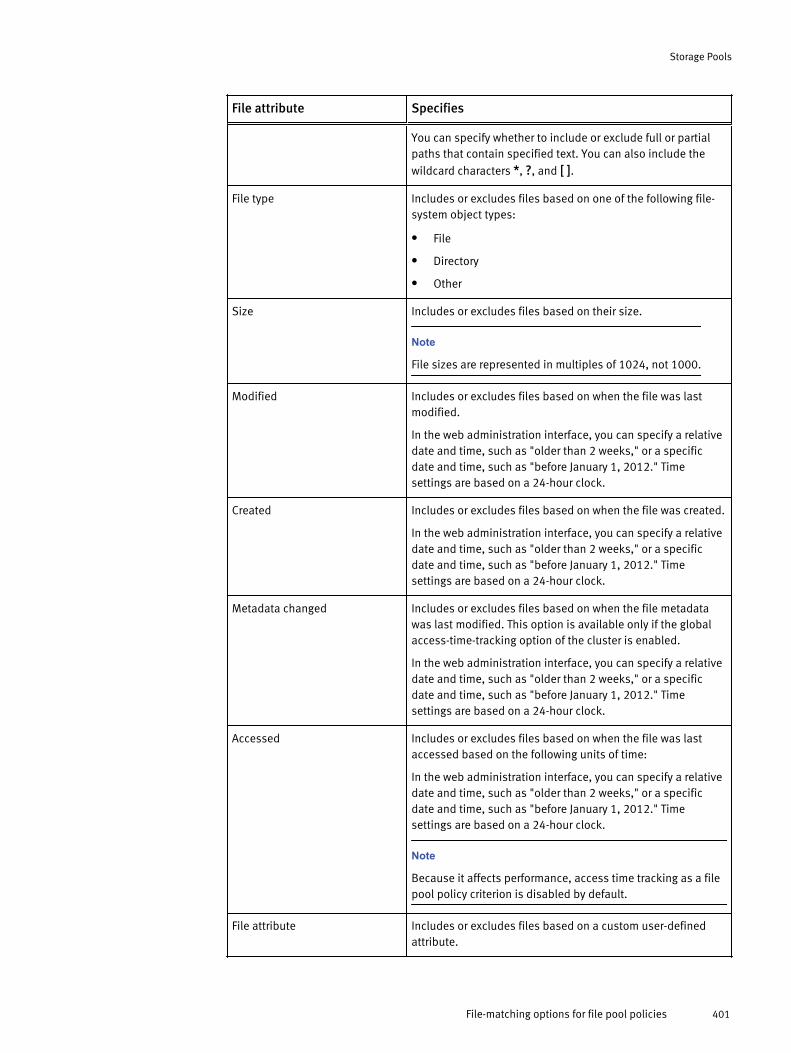
File attribute Specifies
You can specify whether to include or exclude full or partialpaths that contain specified text. You can also include the
wildcard characters *, ?, and [ ].
File type Includes or excludes files based on one of the following file-system object types:
l File
l Directory
l Other
Size Includes or excludes files based on their size.
Note
File sizes are represented in multiples of 1024, not 1000.
Modified Includes or excludes files based on when the file was lastmodified.
In the web administration interface, you can specify a relativedate and time, such as "older than 2 weeks," or a specificdate and time, such as "before January 1, 2012." Timesettings are based on a 24-hour clock.
Created Includes or excludes files based on when the file was created.
In the web administration interface, you can specify a relativedate and time, such as "older than 2 weeks," or a specificdate and time, such as "before January 1, 2012." Timesettings are based on a 24-hour clock.
Metadata changed Includes or excludes files based on when the file metadatawas last modified. This option is available only if the globalaccess-time-tracking option of the cluster is enabled.
In the web administration interface, you can specify a relativedate and time, such as "older than 2 weeks," or a specificdate and time, such as "before January 1, 2012." Timesettings are based on a 24-hour clock.
Accessed Includes or excludes files based on when the file was lastaccessed based on the following units of time:
In the web administration interface, you can specify a relativedate and time, such as "older than 2 weeks," or a specificdate and time, such as "before January 1, 2012." Timesettings are based on a 24-hour clock.
Note
Because it affects performance, access time tracking as a filepool policy criterion is disabled by default.
File attribute Includes or excludes files based on a custom user-definedattribute.
Storage Pools
File-matching options for file pool policies 401
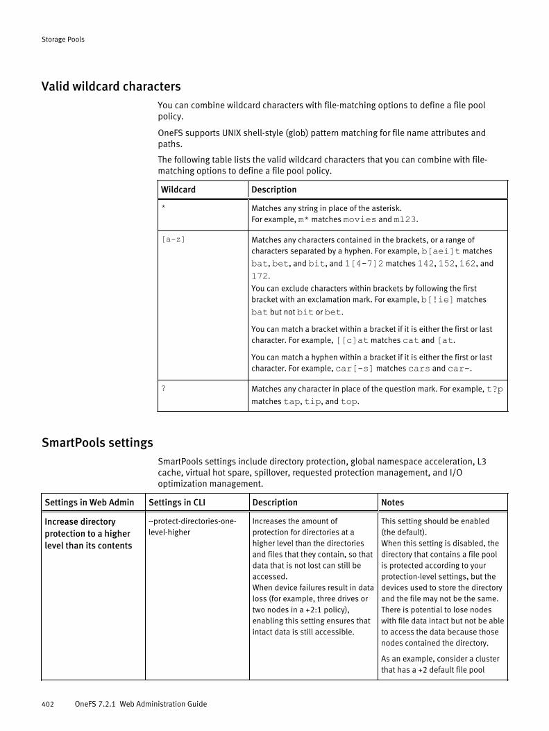
Valid wildcard charactersYou can combine wildcard characters with file-matching options to define a file poolpolicy.
OneFS supports UNIX shell-style (glob) pattern matching for file name attributes andpaths.
The following table lists the valid wildcard characters that you can combine with file-matching options to define a file pool policy.
Wildcard Description
* Matches any string in place of the asterisk.For example, m* matches movies and m123.
[a-z] Matches any characters contained in the brackets, or a range ofcharacters separated by a hyphen. For example, b[aei]t matches
bat, bet, and bit, and 1[4-7]2 matches 142, 152, 162, and
172.
You can exclude characters within brackets by following the firstbracket with an exclamation mark. For example, b[!ie] matches
bat but not bit or bet.
You can match a bracket within a bracket if it is either the first or lastcharacter. For example, [[c]at matches cat and [at.
You can match a hyphen within a bracket if it is either the first or lastcharacter. For example, car[-s] matches cars and car-.
? Matches any character in place of the question mark. For example, t?pmatches tap, tip, and top.
SmartPools settingsSmartPools settings include directory protection, global namespace acceleration, L3cache, virtual hot spare, spillover, requested protection management, and I/Ooptimization management.
Settings in Web Admin Settings in CLI Description Notes
Increase directoryprotection to a higherlevel than its contents
--protect-directories-one-level-higher
Increases the amount ofprotection for directories at ahigher level than the directoriesand files that they contain, so thatdata that is not lost can still beaccessed.When device failures result in dataloss (for example, three drives ortwo nodes in a +2:1 policy),enabling this setting ensures thatintact data is still accessible.
This setting should be enabled(the default).When this setting is disabled, thedirectory that contains a file poolis protected according to yourprotection-level settings, but thedevices used to store the directoryand the file may not be the same.There is potential to lose nodeswith file data intact but not be ableto access the data because thosenodes contained the directory.
As an example, consider a clusterthat has a +2 default file pool
Storage Pools
402 OneFS 7.2.1 Web Administration Guide
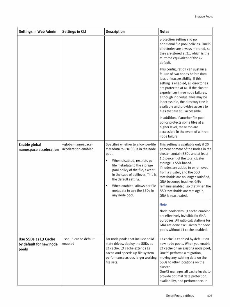
Settings in Web Admin Settings in CLI Description Notes
protection setting and noadditional file pool policies. OneFSdirectories are always mirrored, sothey are stored at 3x, which is themirrored equivalent of the +2default.
This configuration can sustain afailure of two nodes before dataloss or inaccessibility. If thissetting is enabled, all directoriesare protected at 4x. If the clusterexperiences three node failures,although individual files may beinaccessible, the directory tree isavailable and provides access tofiles that are still accessible.
In addition, if another file poolpolicy protects some files at ahigher level, these too areaccessible in the event of a three-node failure.
Enable globalnamespace acceleration
--global-namespace-acceleration-enabled
Specifies whether to allow per-filemetadata to use SSDs in the nodepool.
l When disabled, restricts per-file metadata to the storagepool policy of the file, exceptin the case of spillover. This isthe default setting.
l When enabled, allows per-filemetadata to use the SSDs inany node pool.
This setting is available only if 20percent or more of the nodes in thecluster contain SSDs and at least1.5 percent of the total clusterstorage is SSD-based.If nodes are added to or removedfrom a cluster, and the SSDthresholds are no longer satisfied,GNA becomes inactive. GNAremains enabled, so that when theSSD thresholds are met again,GNA is reactivated.
Note
Node pools with L3 cache enabledare effectively invisible for GNApurposes. All ratio calculations forGNA are done exclusively for nodepools without L3 cache enabled.
Use SSDs as L3 Cacheby default for new nodepools
--ssd-l3-cache-default-enabled
For node pools that include solid-state drives, deploy the SSDs asL3 cache. L3 cache extends L2cache and speeds up file systemperformance across larger workingfile sets.
L3 cache is enabled by default onnew node pools. When you enableL3 cache on an existing node pool,OneFS performs a migration,moving any existing data on theSSDs to other locations on thecluster.OneFS manages all cache levels toprovide optimal data protection,availability, and performance. In
Storage Pools
SmartPools settings 403
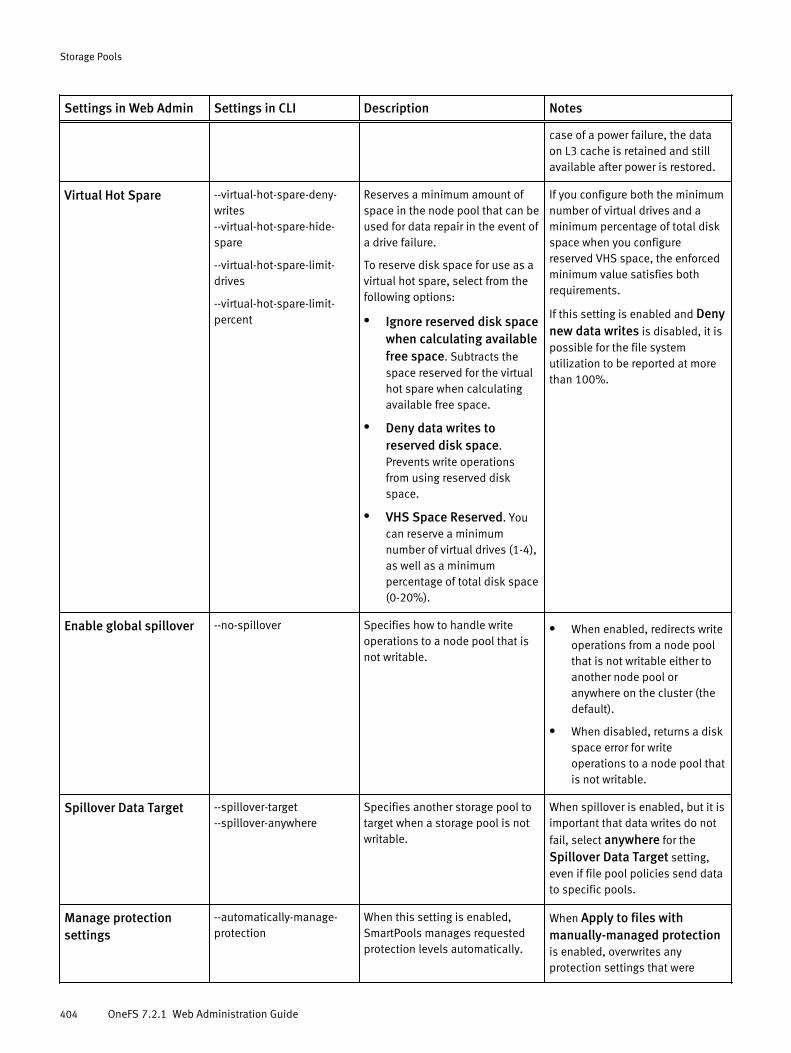
Settings in Web Admin Settings in CLI Description Notes
case of a power failure, the dataon L3 cache is retained and stillavailable after power is restored.
Virtual Hot Spare --virtual-hot-spare-deny-writes--virtual-hot-spare-hide-spare
--virtual-hot-spare-limit-drives
--virtual-hot-spare-limit-percent
Reserves a minimum amount ofspace in the node pool that can beused for data repair in the event ofa drive failure.
To reserve disk space for use as avirtual hot spare, select from thefollowing options:
l Ignore reserved disk spacewhen calculating availablefree space. Subtracts thespace reserved for the virtualhot spare when calculatingavailable free space.
l Deny data writes toreserved disk space.Prevents write operationsfrom using reserved diskspace.
l VHS Space Reserved. Youcan reserve a minimumnumber of virtual drives (1-4),as well as a minimumpercentage of total disk space(0-20%).
If you configure both the minimumnumber of virtual drives and aminimum percentage of total diskspace when you configurereserved VHS space, the enforcedminimum value satisfies bothrequirements.
If this setting is enabled and Denynew data writes is disabled, it ispossible for the file systemutilization to be reported at morethan 100%.
Enable global spillover --no-spillover Specifies how to handle writeoperations to a node pool that isnot writable.
l When enabled, redirects writeoperations from a node poolthat is not writable either toanother node pool oranywhere on the cluster (thedefault).
l When disabled, returns a diskspace error for writeoperations to a node pool thatis not writable.
Spillover Data Target --spillover-target--spillover-anywhere
Specifies another storage pool totarget when a storage pool is notwritable.
When spillover is enabled, but it isimportant that data writes do not
fail, select anywhere for the
Spillover Data Target setting,even if file pool policies send datato specific pools.
Manage protectionsettings
--automatically-manage-protection
When this setting is enabled,SmartPools manages requestedprotection levels automatically.
When Apply to files withmanually-managed protectionis enabled, overwrites anyprotection settings that were
Storage Pools
404 OneFS 7.2.1 Web Administration Guide
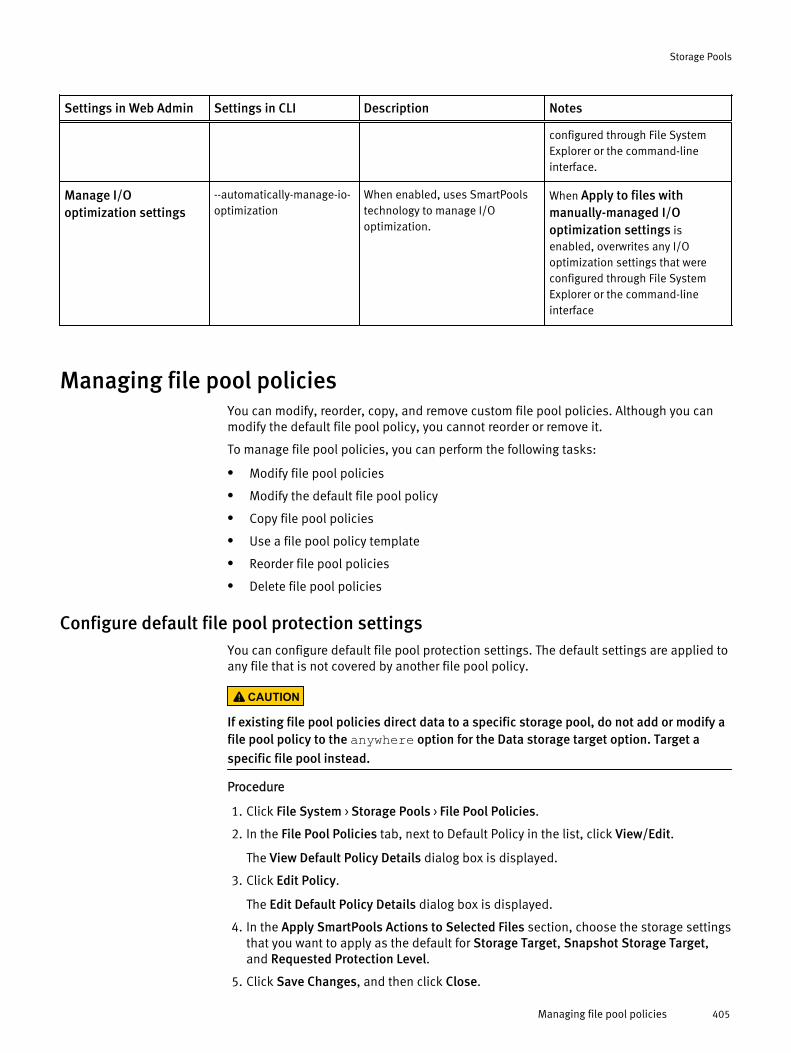
Settings in Web Admin Settings in CLI Description Notes
configured through File SystemExplorer or the command-lineinterface.
Manage I/Ooptimization settings
--automatically-manage-io-optimization
When enabled, uses SmartPoolstechnology to manage I/Ooptimization.
When Apply to files withmanually-managed I/Ooptimization settings isenabled, overwrites any I/Ooptimization settings that wereconfigured through File SystemExplorer or the command-lineinterface
Managing file pool policiesYou can modify, reorder, copy, and remove custom file pool policies. Although you canmodify the default file pool policy, you cannot reorder or remove it.
To manage file pool policies, you can perform the following tasks:
l Modify file pool policies
l Modify the default file pool policy
l Copy file pool policies
l Use a file pool policy template
l Reorder file pool policies
l Delete file pool policies
Configure default file pool protection settingsYou can configure default file pool protection settings. The default settings are applied toany file that is not covered by another file pool policy.
CAUTION
If existing file pool policies direct data to a specific storage pool, do not add or modify afile pool policy to the anywhere option for the Data storage target option. Target a
specific file pool instead.
Procedure
1. Click File System > Storage Pools > File Pool Policies.
2. In the File Pool Policies tab, next to Default Policy in the list, click View/Edit.
The View Default Policy Details dialog box is displayed.
3. Click Edit Policy.
The Edit Default Policy Details dialog box is displayed.
4. In the Apply SmartPools Actions to Selected Files section, choose the storage settingsthat you want to apply as the default for Storage Target, Snapshot Storage Target,and Requested Protection Level.
5. Click Save Changes, and then click Close.
Storage Pools
Managing file pool policies 405
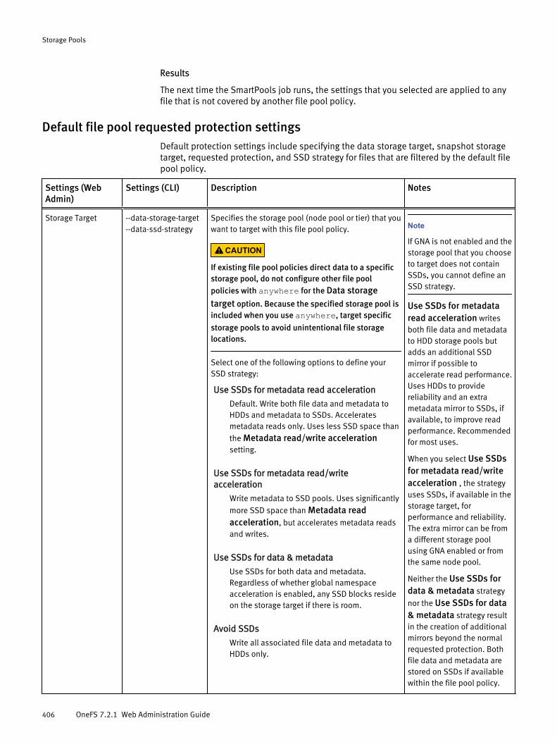
Results
The next time the SmartPools job runs, the settings that you selected are applied to anyfile that is not covered by another file pool policy.
Default file pool requested protection settingsDefault protection settings include specifying the data storage target, snapshot storagetarget, requested protection, and SSD strategy for files that are filtered by the default filepool policy.
Settings (WebAdmin)
Settings (CLI) Description Notes
Storage Target --data-storage-target--data-ssd-strategy
Specifies the storage pool (node pool or tier) that youwant to target with this file pool policy.
CAUTION
If existing file pool policies direct data to a specificstorage pool, do not configure other file pool
policies with anywhere for the Data storagetarget option. Because the specified storage pool isincluded when you use anywhere, target specific
storage pools to avoid unintentional file storagelocations.
Select one of the following options to define yourSSD strategy:
Use SSDs for metadata read acceleration
Default. Write both file data and metadata toHDDs and metadata to SSDs. Acceleratesmetadata reads only. Uses less SSD space than
the Metadata read/write accelerationsetting.
Use SSDs for metadata read/writeacceleration
Write metadata to SSD pools. Uses significantly
more SSD space than Metadata readacceleration, but accelerates metadata readsand writes.
Use SSDs for data & metadata
Use SSDs for both data and metadata.Regardless of whether global namespaceacceleration is enabled, any SSD blocks resideon the storage target if there is room.
Avoid SSDs
Write all associated file data and metadata toHDDs only.
Note
If GNA is not enabled and thestorage pool that you chooseto target does not containSSDs, you cannot define anSSD strategy.
Use SSDs for metadataread acceleration writesboth file data and metadatato HDD storage pools butadds an additional SSDmirror if possible toaccelerate read performance.Uses HDDs to providereliability and an extrametadata mirror to SSDs, ifavailable, to improve readperformance. Recommendedfor most uses.
When you select Use SSDsfor metadata read/writeacceleration , the strategyuses SSDs, if available in thestorage target, forperformance and reliability.The extra mirror can be froma different storage poolusing GNA enabled or fromthe same node pool.
Neither the Use SSDs fordata & metadata strategy
nor the Use SSDs for data& metadata strategy resultin the creation of additionalmirrors beyond the normalrequested protection. Bothfile data and metadata arestored on SSDs if availablewithin the file pool policy.
Storage Pools
406 OneFS 7.2.1 Web Administration Guide

Settings (WebAdmin)
Settings (CLI) Description Notes
CAUTION
Use this to free SSD space only after consultingwith Isilon Technical Support personnel; thesetting can negatively affect performance.
This option requires asignificant amount of SSDstorage.
Snapshot storagetarget
--snapshot-storage-target--snapshot-ssd-strategy
Specifies the storage pool that you want to target forsnapshot storage with this file pool policy. Thesettings are the same as those for data storagetarget, but apply to snapshot data.
Notes for data storage targetapply to snapshot storagetarget
Requestedprotection
--set-requested-protection
Default of storage pool. Assign the defaultrequested protection of the storage pool to thefiltered files.
Specific level. Assign a specified requestedprotection to the filtered files.
To change the requestedprotection , select a newvalue from the list.
Configure default I/O optimization settingsYou can configure default I/O optimization settings.
Procedure
1. Click File System > Storage Pools > File Pool Policies.
2. In the File Pool Policies tab, next to Default Policy in the list, click View/Edit.
The View Default Policy Details dialog box is displayed.
3. Click Edit Policy.
The Edit Default Policy Details dialog box is displayed.
4. In the Apply SmartPools Actions to Selected Files section, under I/O OptimizationSettings,choose the settings that you want to apply as the default for WritePerformance and Data Access Pattern.
5. Click Save Changes, and then click Close.
Results
The next time the SmartPools job runs, the settings that you selected are applied to anyfile that is not covered by another file pool policy.
Default file pool I/O optimization settingsYou can manage the I/O optimization settings that are used in the default file pool policy,which can include files with manually managed attributes.
To allow SmartPools to overwrite optimization settings that were configured using FileSystem Explorer or the isi set command, select the Including files with manually-managed I/O optimization settings option in the Default Protection Settings group. Inthe CLI, use the --automatically-manage-io-optimization option with theisi storagepool settings modify command.
Storage Pools
Configure default I/O optimization settings 407
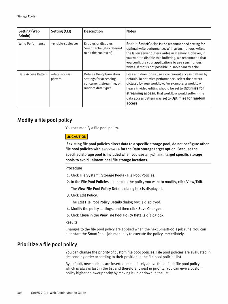
Setting (WebAdmin)
Setting (CLI) Description Notes
Write Performance --enable-coalescer Enables or disablesSmartCache (also referredto as the coalescer).
Enable SmartCache is the recommended setting foroptimal write performance. With asynchronous writes,the Isilon server buffers writes in memory. However, ifyou want to disable this buffering, we recommend thatyou configure your applications to use synchronouswrites. If that is not possible, disable SmartCache.
Data Access Pattern --data-access-pattern
Defines the optimizationsettings for accessingconcurrent, streaming, orrandom data types.
Files and directories use a concurrent access pattern bydefault. To optimize performance, select the patterndictated by your workflow. For example, a workflow
heavy in video editing should be set to Optimize forstreaming access. That workflow would suffer if the
data access pattern was set to Optimize for randomaccess.
Modify a file pool policyYou can modify a file pool policy.
CAUTION
If existing file pool policies direct data to a specific storage pool, do not configure otherfile pool policies with anywhere for the Data storage target option. Because the
specified storage pool is included when you use anywhere, target specific storage
pools to avoid unintentional file storage locations.
Procedure
1. Click File System > Storage Pools > File Pool Policies.
2. In the File Pool Policies list, next to the policy you want to modify, click View/Edit.
The View File Pool Policy Details dialog box is displayed.
3. Click Edit Policy.
The Edit File Pool Policy Details dialog box is displayed.
4. Modify the policy settings, and then click Save Changes.
5. Click Close in the View File Pool Policy Details dialog box.
Results
Changes to the file pool policy are applied when the next SmartPools job runs. You canalso start the SmartPools job manually to execute the policy immediately.
Prioritize a file pool policyYou can change the priority of custom file pool policies. File pool policies are evaluated indescending order according to their position in the file pool policies list.
By default, new policies are inserted immediately above the default file pool policy,which is always last in the list and therefore lowest in priority. You can give a custompolicy higher or lower priority by moving it up or down in the list.
Storage Pools
408 OneFS 7.2.1 Web Administration Guide
Procedure
1. Click File System > Storage Pools > File Pool Policies.
The File Pool Policies tab displays two lists: File Pool Policies and Policy Templates.
2. In the File Pool Policies list, in the Order column, click an arrow icon next to a policy tomove it up or down in the priority order.
3. Repeat the above step for each policy whose priority you want to change.
Results
When the SmartPools system job runs, it processes the file pool policies in priority order.The default file pool policy is applied to all files that are not matched by any other filepool policy.
Create a file pool policy from a templateYou can create a new file pool policy from a policy template. The templates are pre-configured for typical work flows, such as archiving older files or managing virtualmachines (.vmdk files).
Procedure
1. Click File System > Storage Pools > File Pool Policies.
The File Pool Policies tab provides two lists: File Pool Policies and Policy Templates.
2. In the Policy Templates list, next to the template name that you want to use, clickView/Use Template.
The View File Pool Policy Template Details dialog box opens.
3. Click Use Template.
The Create a File Pool Policy dialog box opens.
4. (Required) Specify a policy name and description, and modify any of the policysettings.
5. Click Create Policy.
Results
The new custom policy is added to the File Pool Policies list directly above the defaultpolicy.
Delete a file pool policyYou can delete any file pool policy except the default policy.
When you delete a file pool policy, its file pool is controlled either by another file poolpolicy or by the default policy the next time the SmartPools job runs.
Procedure
1. Click File System > Storage Pools > File Pool Policies.
The File Pool Policies tab displays two lists: File Pool Policies and Policy Templates.
2. In the File Pool Policies list, next to the policy that you want to delete, click More >Delete Policy.
3. In the Confirm Delete dialog box, click Delete.
Results
The file pool policy is removed from the File Pool Policies list.
Storage Pools
Create a file pool policy from a template 409
Monitoring storage poolsYou can access information on storage pool health and usage.
The following information is available:
l File pool policy health
l SmartPools health, including tiers, node pools, and subpools
l For each storage pool, percentage of HDD and SSD disk space usage
l SmartPools job status
Monitor storage poolsYou can view the status of file pool policies, SmartPools, and settings.
Procedure
1. Click File System > Storage Pools > Summary.
The Summary tab displays two areas: the Status list and the Local Storage Usagegraph.
2. In the Status list, check the status of policies, SmartPools, and SmartPools settings.
3. (Optional) If the status of an item is other than Good, you can click View Details toview and fix any issues.
4. In the Local Storage Usage area, view the statistics associated with each node pool.
If node pool usage is unbalanced, for example, you might want to consider whether tomodify your file pool policies.
View subpools healthOneFS exposes unhealthy subpools in a list so that you can correct any issues.
A subpool is otherwise known as a disk pool, a collection of disks that is part of a nodepool.
Procedure
1. Click File System > Storage Pools > SmartPools.
The SmartPools tab displays three groupings: Tiers & Node Pools, Compatibilities,and Subpools Health.
2. In the Subpools Health area, review details of, and mitigate, any unhealthy subpools.
View the results of a SmartPools jobYou can review detailed results from the last time the SmartPools job ran.
Procedure
1. Click Cluster Management > Job Operations > Job Reports.
The Jobs Reports tab displays a list of job reports.
2. In the Job Reports list, in the Type column, find the latest SmartPools job, and clickView Details.
The View Job Report Details dialog box opens, displaying the job report.
Storage Pools
410 OneFS 7.2.1 Web Administration Guide

3. Scroll through the report to see the results of each file pool policy.
4. Click Close in the View Job Report Details dialog box when you are finished.
Storage Pools
View the results of a SmartPools job 411

Storage Pools
412 OneFS 7.2.1 Web Administration Guide

CHAPTER 22
System jobs
This section contains the following topics:
l System jobs overview..........................................................................................414l System jobs library..............................................................................................414l Job operation...................................................................................................... 417l Job performance impact...................................................................................... 418l Job priorities....................................................................................................... 419l Managing system jobs........................................................................................ 419l Managing impact policies................................................................................... 422l Viewing job reports and statistics........................................................................424
System jobs 413
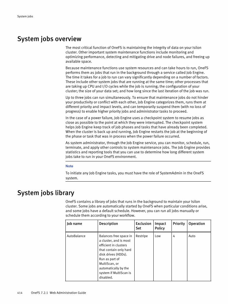
System jobs overviewThe most critical function of OneFS is maintaining the integrity of data on your Isiloncluster. Other important system maintenance functions include monitoring andoptimizing performance, detecting and mitigating drive and node failures, and freeing upavailable space.
Because maintenance functions use system resources and can take hours to run, OneFSperforms them as jobs that run in the background through a service called Job Engine.The time it takes for a job to run can vary significantly depending on a number of factors.These include other system jobs that are running at the same time; other processes thatare taking up CPU and I/O cycles while the job is running; the configuration of yourcluster; the size of your data set; and how long since the last iteration of the job was run.
Up to three jobs can run simultaneously. To ensure that maintenance jobs do not hinderyour productivity or conflict with each other, Job Engine categorizes them, runs them atdifferent priority and impact levels, and can temporarily suspend them (with no loss ofprogress) to enable higher priority jobs and administrator tasks to proceed.
In the case of a power failure, Job Engine uses a checkpoint system to resume jobs asclose as possible to the point at which they were interrupted. The checkpoint systemhelps Job Engine keep track of job phases and tasks that have already been completed.When the cluster is back up and running, Job Engine restarts the job at the beginning ofthe phase or task that was in process when the power failure occurred.
As system administrator, through the Job Engine service, you can monitor, schedule, run,terminate, and apply other controls to system maintenance jobs. The Job Engine providesstatistics and reporting tools that you can use to determine how long different systemjobs take to run in your OneFS environment.
Note
To initiate any Job Engine tasks, you must have the role of SystemAdmin in the OneFSsystem.
System jobs libraryOneFS contains a library of jobs that runs in the background to maintain your Isiloncluster. Some jobs are automatically started by OneFS when particular conditions arise,and some jobs have a default schedule. However, you can run all jobs manually orschedule them according to your workflow.
Job name Description ExclusionSet
ImpactPolicy
Priority Operation
AutoBalance Balances free space ina cluster, and is mostefficient in clustersthat contain only harddisk drives (HDDs).Run as part ofMultiScan, orautomatically by thesystem if MultiScan isdisabled.
Restripe Low 4 Auto
System jobs
414 OneFS 7.2.1 Web Administration Guide
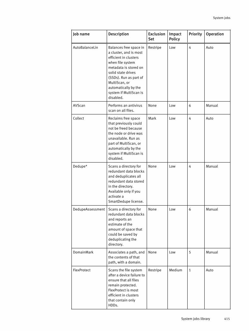
Job name Description ExclusionSet
ImpactPolicy
Priority Operation
AutoBalanceLin Balances free space ina cluster, and is mostefficient in clusterswhen file systemmetadata is stored onsolid state drives(SSDs). Run as part ofMultiScan, orautomatically by thesystem if MultiScan isdisabled.
Restripe Low 4 Auto
AVScan Performs an antivirusscan on all files.
None Low 6 Manual
Collect Reclaims free spacethat previously couldnot be freed becausethe node or drive wasunavailable. Run aspart of MultiScan, orautomatically by thesystem if MultiScan isdisabled.
Mark Low 4 Auto
Dedupe* Scans a directory forredundant data blocksand deduplicates allredundant data storedin the directory.Available only if youactivate aSmartDedupe license.
None Low 4 Manual
DedupeAssessment Scans a directory forredundant data blocksand reports anestimate of theamount of space thatcould be saved bydeduplicating thedirectory.
None Low 6 Manual
DomainMark Associates a path, andthe contents of thatpath, with a domain.
None Low 5 Manual
FlexProtect Scans the file systemafter a device failure toensure that all filesremain protected.FlexProtect is mostefficient in clustersthat contain onlyHDDs.
Restripe Medium 1 Auto
System jobs
System jobs library 415
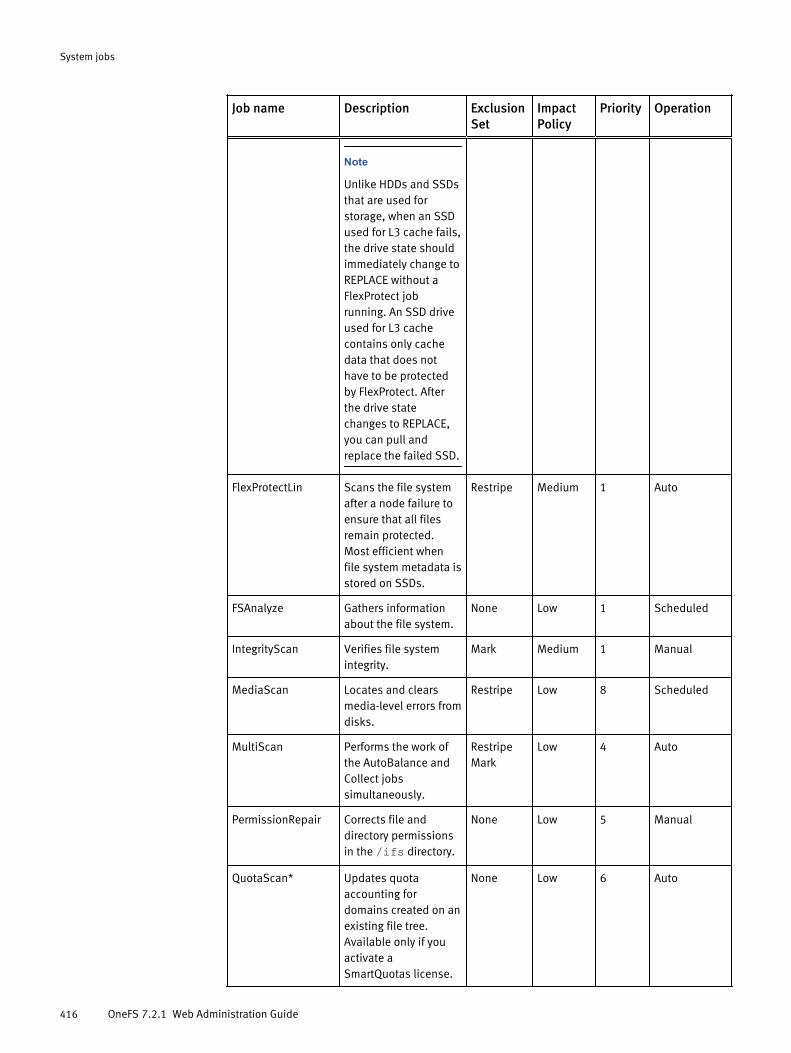
Job name Description ExclusionSet
ImpactPolicy
Priority Operation
Note
Unlike HDDs and SSDsthat are used forstorage, when an SSDused for L3 cache fails,the drive state shouldimmediately change toREPLACE without aFlexProtect jobrunning. An SSD driveused for L3 cachecontains only cachedata that does nothave to be protectedby FlexProtect. Afterthe drive statechanges to REPLACE,you can pull andreplace the failed SSD.
FlexProtectLin Scans the file systemafter a node failure toensure that all filesremain protected.Most efficient whenfile system metadata isstored on SSDs.
Restripe Medium 1 Auto
FSAnalyze Gathers informationabout the file system.
None Low 1 Scheduled
IntegrityScan Verifies file systemintegrity.
Mark Medium 1 Manual
MediaScan Locates and clearsmedia-level errors fromdisks.
Restripe Low 8 Scheduled
MultiScan Performs the work ofthe AutoBalance andCollect jobssimultaneously.
RestripeMark
Low 4 Auto
PermissionRepair Corrects file anddirectory permissionsin the /ifs directory.
None Low 5 Manual
QuotaScan* Updates quotaaccounting fordomains created on anexisting file tree.Available only if youactivate aSmartQuotas license.
None Low 6 Auto
System jobs
416 OneFS 7.2.1 Web Administration Guide
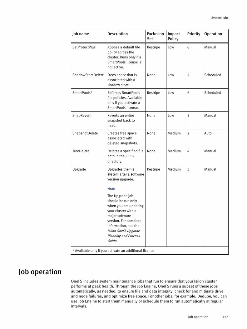
Job name Description ExclusionSet
ImpactPolicy
Priority Operation
SetProtectPlus Applies a default filepolicy across thecluster. Runs only if aSmartPools license isnot active.
Restripe Low 6 Manual
ShadowStoreDelete Frees space that isassociated with ashadow store.
None Low 2 Scheduled
SmartPools* Enforces SmartPoolsfile policies. Availableonly if you activate aSmartPools license.
Restripe Low 6 Scheduled
SnapRevert Reverts an entiresnapshot back tohead.
None Low 5 Manual
SnapshotDelete Creates free spaceassociated withdeleted snapshots.
None Medium 2 Auto
TreeDelete Deletes a specified filepath in the /ifsdirectory.
None Medium 4 Manual
Upgrade Upgrades the filesystem after a softwareversion upgrade.
Note
The Upgrade jobshould be run onlywhen you are updatingyour cluster with amajor softwareversion. For completeinformation, see theIsilon OneFS UpgradePlanning and ProcessGuide.
Restripe Medium 3 Manual
* Available only if you activate an additional license
Job operationOneFS includes system maintenance jobs that run to ensure that your Isilon clusterperforms at peak health. Through the Job Engine, OneFS runs a subset of these jobsautomatically, as needed, to ensure file and data integrity, check for and mitigate driveand node failures, and optimize free space. For other jobs, for example, Dedupe, you canuse Job Engine to start them manually or schedule them to run automatically at regularintervals.
System jobs
Job operation 417
The Job Engine runs system maintenance jobs in the background and prevents jobswithin the same classification (exclusion set) from running simultaneously. Two exclusionsets are enforced: restripe and mark.
Restripe job types are:
l AutoBalance
l AutoBalanceLin
l FlexProtect
l FlexProtectLin
l MediaScan
l MultiScan
l SetProtectPlus
l SmartPools
Mark job types are:
l Collect
l IntegrityScan
l MultiScan
Note that MultiScan is a member of both the restripe and mark exclusion sets. Youcannot change the exclusion set parameter for a job type.
The Job Engine is also sensitive to job priority, and can run up to three jobs, of anypriority, simultaneously. Job priority is denoted as 1–10, with 1 being the highest and 10being the lowest. The system uses job priority when a conflict among running or queuedjobs arises. For example, if you manually start a job that has a higher priority than threeother jobs that are already running, Job Engine pauses the lowest-priority active job, runsthe new job, then restarts the older job at the point at which it was paused. Similarly, ifyou start a job within the restripe exclusion set, and another restripe job is alreadyrunning, the system uses priority to determine which job should run (or remain running)and which job should be paused (or remain paused).
Other job parameters determine whether jobs are enabled, their performance impact, andschedule. As system administrator, you can accept the job defaults or adjust theseparameters (except for exclusion set) based on your requirements.
When a job starts, the Job Engine distributes job segments—phases and tasks—acrossthe nodes of your cluster. One node acts as job coordinator and continually works withthe other nodes to load-balance the work. In this way, no one node is overburdened, andsystem resources remain available for other administrator and system I/O activities notoriginated from the Job Engine.
After completing a task, each node reports task status to the job coordinator. The nodeacting as job coordinator saves this task status information to a checkpoint file.Consequently, in the case of a power outage, or when paused, a job can always berestarted from the point at which it was interrupted. This is important because some jobscan take hours to run and can use considerable system resources.
Job performance impactThe Job Engine service monitors system performance to ensure that maintenance jobs donot significantly interfere with regular cluster I/O activity and other system administration
System jobs
418 OneFS 7.2.1 Web Administration Guide
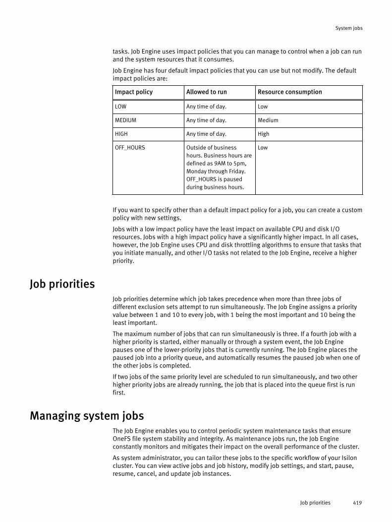
tasks. Job Engine uses impact policies that you can manage to control when a job can runand the system resources that it consumes.
Job Engine has four default impact policies that you can use but not modify. The defaultimpact policies are:
Impact policy Allowed to run Resource consumption
LOW Any time of day. Low
MEDIUM Any time of day. Medium
HIGH Any time of day. High
OFF_HOURS Outside of businesshours. Business hours aredefined as 9AM to 5pm,Monday through Friday.OFF_HOURS is pausedduring business hours.
Low
If you want to specify other than a default impact policy for a job, you can create a custompolicy with new settings.
Jobs with a low impact policy have the least impact on available CPU and disk I/Oresources. Jobs with a high impact policy have a significantly higher impact. In all cases,however, the Job Engine uses CPU and disk throttling algorithms to ensure that tasks thatyou initiate manually, and other I/O tasks not related to the Job Engine, receive a higherpriority.
Job prioritiesJob priorities determine which job takes precedence when more than three jobs ofdifferent exclusion sets attempt to run simultaneously. The Job Engine assigns a priorityvalue between 1 and 10 to every job, with 1 being the most important and 10 being theleast important.
The maximum number of jobs that can run simultaneously is three. If a fourth job with ahigher priority is started, either manually or through a system event, the Job Enginepauses one of the lower-priority jobs that is currently running. The Job Engine places thepaused job into a priority queue, and automatically resumes the paused job when one ofthe other jobs is completed.
If two jobs of the same priority level are scheduled to run simultaneously, and two otherhigher priority jobs are already running, the job that is placed into the queue first is runfirst.
Managing system jobsThe Job Engine enables you to control periodic system maintenance tasks that ensureOneFS file system stability and integrity. As maintenance jobs run, the Job Engineconstantly monitors and mitigates their impact on the overall performance of the cluster.
As system administrator, you can tailor these jobs to the specific workflow of your Isiloncluster. You can view active jobs and job history, modify job settings, and start, pause,resume, cancel, and update job instances.
System jobs
Job priorities 419
View active jobsIf you are noticing slower system response while performing administrative tasks, youcan view jobs that are currently running on your Isilon cluster.
Procedure
1. Click Cluster Management > Job Operations > Job Summary.
2. In the Active Jobs table, view status information about all currently running jobs, jobsettings, and progress details.
a. You can perform bulk actions on the active jobs by selecting the Status check box,then selecting an action from the Select a bulk action drop-down list.
View job historyIf you want to check the last time a critical job ran, you can view recent activity for aspecific job, or for all jobs.
Procedure
1. Click Cluster Management > Job Operations > Job Reports.
The Job Reports table displays a chronological list of the last ten job events that haveoccurred on the cluster. Event information includes the time the event occurred, thejob responsible for the event, and event results.
2. Filter reports by job type by selecting the job from the Filter by Job Type drop-down listand clicking Reset.
3. Click on View Details next to a job name to view recent events for only that job.
Recent events for the job appear in the View Job Report Details window, and includeinformation such as start time, duration, and whether or not the job was successful.
Start a jobBy default, only some system maintenance jobs are scheduled to run automatically.However, you can start any of the jobs manually at any time.
Procedure
1. Click Cluster Management > Job Operations > Job Summary.
2. In the Active Jobs window, select the job you want to start and click More.
3. Click Start Running Job.
Pause a jobYou can pause a job temporarily to free up system resources.
Procedure
1. Click Cluster Management > Job Operations > Job Summary.
2. In the Active Jobs table, click More for the job that you want to pause.
3. Click Pause Running Job in the menu that appears.
The job remains paused until you resume it.
System jobs
420 OneFS 7.2.1 Web Administration Guide
Resume a jobYou can resume a paused job.
Procedure
1. Click Cluster Management > Job Operations > Job Summary.
2. In the Active Jobs table, click More for the job that you want to pause.
3. Click Resume Running Job in the menu that appears.
Results
The job continues from the phase or task at which it was paused.
Cancel a jobIf you want to free up system resources, or for any reason, you can permanentlydiscontinue a running, paused, or waiting job.
Procedure
1. Click Cluster Management > Job Operations > Job Summary.
2. In the Active Jobs table, click More for the job that you want to cancel.
3. Click Cancel Running Job in the menu that appears.
Update a jobYou can change the priority and impact policy of a running, waiting, or paused job.
When you update a job, only the current instance of the job runs with the updatedsettings. The next instance of the job returns to the default settings for that job.
Note
To change job settings permanently, see "Modify job type settings."
Procedure
1. Click Cluster Management > Job Operations > Job Summary.
2. In the Active Jobs table, click View/Edit for the job that you want to update.
3. (Required) In the View Active Job Details window, click Edit Job.
a. Select a new priority level from the Priority drop-down list.
b. Select an impact policy level from the Impact Policy drop-down list.
4. Click Save Changes.
When you update a running job, the job automatically resumes. When you update apaused or idle job, the job remains in that state until you restart it.
Modify job type settingsYou can customize system maintenance jobs for your administrative workflow bymodifying the default priority level, impact level, and schedule for a job type.
Procedure
1. Click Cluster Management > Job Operations > Job Types.
2. In the Job Types table, locate the row for the policy you want to modify and clickView / Edit.
System jobs
Resume a job 421
The View Job Type Details window appears, displaying current default settings,schedule, current state, and recent activity.
3. Click Edit Job Type. The Edit Job Type Details window appears.
4. Modify the details you want to change. You can modify the default priority, the defaultimpact policy, whether the job is enabled, and whether the job runs manually or on aschedule.
5. Click Scheduled to modify a job schedule, then select the schedule option from thedrop-down list.
6. Click Save Changes.
The modifications are saved and applied to all instances of that job type. The resultsare shown in the View Job Type Details window.
7. Click Close.
Managing impact policiesFor system maintenance jobs that run through the Job Engine service, you can create andassign policies that help control how jobs affect system performance.
As system administrator, you can create, copy, modify, and delete impact policies, andview their settings.
Create an impact policyThe Job Engine includes four impact policies, which you cannot modify or delete.However, you can create and configure new impact policies.
Procedure
1. Click Cluster Management > Job Operations > Impact Policies.
2. Click Add an Impact Policy.
The Create Impact Policy window appears.
3. In the Name text field, type a name for the policy. This field is required.
4. (Required) In the Description text field, type a comment about the impact policy.
Include information specific to the impact policy such as unique schedule parametersor logistical requirements that make the impact policy necessary.
5. Click Add an Impact Policy Interval.
a. In the Add an Impact Policy Interval window, select the impact level and start andend times from the drop-down lists.
b. Click Add Impact Policy Interval.
The Add an Impact Policy Interval window disappears, and the settings you selectedappear in the Impact Schedule table.
6. Click Create Impact Policy.
Your copy of the impact policy is saved and is listed in alphabetical order in theImpact Policies table.
System jobs
422 OneFS 7.2.1 Web Administration Guide
Copy an impact policyYou can use a default impact policy as the template for a new policy by making andmodifying a copy.
Procedure
1. Click Cluster Management > Job Operations > Impact Policies.
2. In the Impact Policies table, locate the row for the policy you want to copy and clickMore. The Copy Impact Policy window appears.
3. In the Name field, type a name for the new policy.
4. In the Description text field, enter a description for the new policy.
Include information specific to the impact policy such as unique schedule parametersor logistical requirements that make the impact policy necessary.
5. Click Add an Impact Policy Interval.
a. In the Add an Impact Policy Interval window, select the impact level and start andend times from the drop-down lists.
b. Click Add Impact Policy Interval.
The Add an Impact Policy Interval window closes, and the settings you selectedappear in the Impact Schedule table.
6. Click Copy Impact Policy.
Your copy of the impact policy is saved and is listed in alphabetical order in theImpact Policies table.
Modify an impact policyYou can change the name, description, and impact intervals of a custom impact policy.
Before you begin
You cannot modify the default impact policies, HIGH, MEDIUM, LOW, and OFF_HOURS. Ifyou want to modify a policy, create and modify a copy of a default policy.
Procedure
1. Navigate to Cluster Management > Job Operations > Impact Policies.
2. In the Impact Policies table, click View / Edit for the policy you want to modify.
The Edit Impact Policy window appears.
3. Click Edit Impact Policy, and modify one or all of the following:
Option Description
Policy description a. In the Description field, type a new overview for the impactpolicy.
b. Click Submit.
Impact schedule a. In the Impact Schedule area, modify the schedule of theimpact policy by adding, editing, or deleting impact intervals.
b. Click Save Changes.
System jobs
Copy an impact policy 423
The modified impact policy is saved and listed in alphabetical order in the ImpactPolicies table.
Delete an impact policyYou can delete impact policies that you have created.
You cannot delete default impact policies, HIGH, MEDIUM, LOW, and OFF_HOURS.
Procedure
1. Click Cluster Management > Job Operations > Impact Policies.
2. In the Impact Policies table, click More next to the custom impact policy that you wantto delete.
3. Click Delete.
A confirmation dialog box appears.
4. In the confirmation dialog box, click Delete.
View impact policy settingsYou can view the impact policy settings for any job.
Procedure
1. Click Cluster Management > Job Operations > Job Types.
The Job Types table is displayed.
2. If necessary, scroll through the Job Types table to find a specific job.
The impact policy settings for the job are shown in the Job Types table.
Viewing job reports and statisticsYou can generate reports for system jobs and view statistics to better determine theamounts of system resources being used.
Most system jobs controlled by the Job Engine run at a low priority and with a low impactpolicy, and generally do not have a noticeable impact on cluster performance.
A few jobs, because of the critical functions they perform, run at a higher priority and witha medium impact policy. These jobs include FlexProtect and FlexProtect Lin, FSAnalyze,SnapshotDelete, and TreeDelete.
As a system administrator, if you are concerned about the impact a system job mighthave on cluster performance, you can view job statistics and reports. These tools enableyou to view detailed information about job load, including CPU and memory usage andI/O operations.
View statistics for a job in progressYou can view statistics for a job in progress.
Procedure
1. Click Cluster Management > Job Operations > Job Summary.
You can view jobs that are running in the Active Jobs area.
2. Click the View/Edit option to the right of the job entry.
System jobs
424 OneFS 7.2.1 Web Administration Guide
Results
The View Active Jobs Details screen opens, where you can view statistics such asprocessed data, elapsed time, phase, and progress, including an estimate of the timeremaining for the job to complete.
View a report for a completed jobAfter a job finishes, you can view a report about the job.
Before you begin
A report for a job is not available until after the job is completed.
Procedure
1. Click Cluster Management > Job Operations > Job Reports.
The Job Reports screen appears with a list of the last 10 completed jobs.
2. Locate the job whose report you want to view.
If the job is not on the first page of the Job Reports screen, click the right-arrow icon topage through the list until you locate your job.
3. Click View Details.
The View Job Report Details screen appears, listing job statistics such as elapsedtime, CPU and memory usage, and total I/O operations.
4. When you are finished viewing the report, click Close.
System jobs
View a report for a completed job 425

System jobs
426 OneFS 7.2.1 Web Administration Guide
CHAPTER 23
Networking
This section contains the following topics:
l Networking overview........................................................................................... 428l Internal network overview................................................................................... 428l External client network overview......................................................................... 429l Configuring the internal network......................................................................... 437l Configuring an external network.......................................................................... 439l Managing external client connections with SmartConnect................................... 455l Managing network interface provisioning rules....................................................456l Managing routing options................................................................................... 458
Networking 427
Networking overviewAfter you determine the topology of your network, you can set up and manage yourinternal and external networks.
There are two types of networks associated with an EMC Isilon cluster:
Internal
Nodes communicate with each other using a high speed low latency InfiniBandnetwork. You can optionally configure a second InfiniBand network as a failover forredundancy.
External
Clients connect to the cluster through the external network with Ethernet. The Isiloncluster supports standard network communication protocols, including NFS, SMB,HTTP, and FTP. The cluster includes various external Ethernet connections, providingflexibility for a wide variety of network configurations. External network speeds varyby product.
Internal network overviewThe EMC Isilon cluster must connect to at least one high-speed, low-latency InfiniBandswitch for internal communications and data transfer. The connection to the InfiniBandswitch is also referred to as an internal network. The internal network is separate from theexternal network (Ethernet) by which users access the cluster.
Upon initial configuration of your cluster, OneFS creates a default internal network for theInfiniBand switch. The interface to the default internal network is int-a. An internalnetwork for a second InfiniBand switch can be added for redundancy and failover.Failover allows continuous connectivity during path failures. The interface to the defaultinternal network is int-b, which is referred to as int-b/failover in the web administrationinterface.
Internal IP address rangesThe number of IP addresses assigned to the internal network determines how manynodes can be joined to the EMC Isilon cluster.
When you initially configure the cluster, you specify one or more IP address ranges for theinternal InfiniBand network. This range of addresses is used by the nodes tocommunicate with each other. It is recommended that you create a range of addresseslarge enough to accommodate adding additional nodes to your cluster. If the IP addressrange defined during the initial configuration is too restrictive for the size of the internalnetwork, you can add ranges to the int-a network and int-b network. For certainconfiguration changes, such as deleting an IP address assigned to a node, the clustermust be restarted.
While all clusters will have, at minimum, one internal InfiniBand network (int-a), toenable a second internal network (int-b) you must assign another IP address range to it.To enable internal network failover, assign an IP address range to the failover network.This range is used to refer to the actual IP addresses in use to provide seamless internalIP address failover.
Networking
428 OneFS 7.2.1 Web Administration Guide
Internal network failoverYou can configure an internal switch as a failover network to provide redundancy for intra-cluster communications.
Enable an internal failover network by connecting the int-a interfaces of each node in thecluster to one switch, connecting the int-b ports on each node to another switch, andthen restarting the EMC Isilon cluster.
In addition to the IP address range assigned to the int-a internal network, if you enablefailover on a second InfiniBand switch, you must assign an IP address range that pointsto actual IP addresses used by the cluster. These addresses enable seamless failover inthe event that either the int-a or int-b switches fail.
External client network overviewYou connect a client computer to the EMC Isilon cluster through the external network.OneFS supports network subnets, IP address pools, and features network provisioningrules to simplify configuration.
Subnets simplify external (front-end) network management and provide flexibility inimplementing and maintaining the cluster network. You can create IP address poolswithin subnets to partition your network interfaces according to workflow or node type.You can configure external network settings through provisioning rules, and then thoserules are applied to nodes that are added to the cluster.
IP address pools can be associated with a node or a group of nodes as well as with theNIC ports on the nodes. For example, based on the network traffic that you expect, youmight decide to establish one subnet for storage nodes and another subnet foraccelerator nodes.
How you set up your external network subnets depends on your network topology. In abasic network topology where all client-node communication occurs through a singlegateway, only a single external subnet is required. If clients connect through multiplesubnets or internal connections, you must configure multiple external network subnets.
External network settingsA default external network subnet is created during the initial set up of your EMC Isiloncluster. You can make modifications to this subnet, create new subnets, and makeadditional configuration changes to the external network.
During initial cluster setup, OneFS performs the following actions:
l Creates a default external network subnet called subnet0, with the specifiednetmask, gateway, and SmartConnect service address.
l Creates a default IP address pool called pool0 with the specified IP address range,the SmartConnect zone name, and the external interface of the first node in thecluster as the only member.
l Creates a default network provisioning rule called rule0, which automatically assignsthe first external interface for all newly added nodes to pool0.
l Adds pool0 to subnet0 and configures pool0 to use the virtual IP of subnet0 as itsSmartConnect service address.
l Sets the global, outbound DNS settings to the domain name server list and DNSsearch list, if provided.
Once the initial external network has been established, you can configure the followinginformation about your external network:
Networking
Internal network failover 429
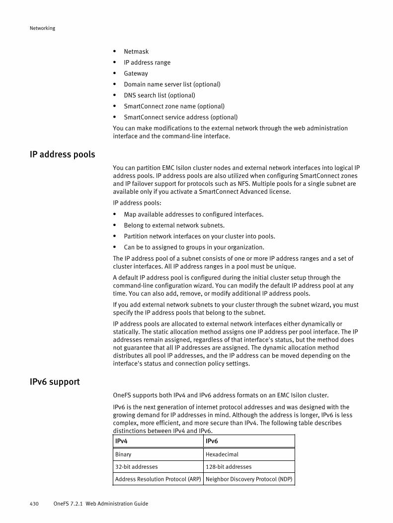
l Netmask
l IP address range
l Gateway
l Domain name server list (optional)
l DNS search list (optional)
l SmartConnect zone name (optional)
l SmartConnect service address (optional)
You can make modifications to the external network through the web administrationinterface and the command-line interface.
IP address poolsYou can partition EMC Isilon cluster nodes and external network interfaces into logical IPaddress pools. IP address pools are also utilized when configuring SmartConnect zonesand IP failover support for protocols such as NFS. Multiple pools for a single subnet areavailable only if you activate a SmartConnect Advanced license.
IP address pools:
l Map available addresses to configured interfaces.
l Belong to external network subnets.
l Partition network interfaces on your cluster into pools.
l Can be to assigned to groups in your organization.
The IP address pool of a subnet consists of one or more IP address ranges and a set ofcluster interfaces. All IP address ranges in a pool must be unique.
A default IP address pool is configured during the initial cluster setup through thecommand-line configuration wizard. You can modify the default IP address pool at anytime. You can also add, remove, or modify additional IP address pools.
If you add external network subnets to your cluster through the subnet wizard, you mustspecify the IP address pools that belong to the subnet.
IP address pools are allocated to external network interfaces either dynamically orstatically. The static allocation method assigns one IP address per pool interface. The IPaddresses remain assigned, regardless of that interface's status, but the method doesnot guarantee that all IP addresses are assigned. The dynamic allocation methoddistributes all pool IP addresses, and the IP address can be moved depending on theinterface's status and connection policy settings.
IPv6 supportOneFS supports both IPv4 and IPv6 address formats on an EMC Isilon cluster.
IPv6 is the next generation of internet protocol addresses and was designed with thegrowing demand for IP addresses in mind. Although the address is longer, IPv6 is lesscomplex, more efficient, and more secure than IPv4. The following table describesdistinctions between IPv4 and IPv6.
IPv4 IPv6
Binary Hexadecimal
32-bit addresses 128-bit addresses
Address Resolution Protocol (ARP) Neighbor Discovery Protocol (NDP)
Networking
430 OneFS 7.2.1 Web Administration Guide
You can configure the Isilon cluster for IPv4, IPv6, or both (dual-stack) in OneFS. You setthe IP family when creating a subnet, and all IP address pools assigned to the subnetmust use the selected format.
Note
If your EMC Isilon cluster must comply with United States federal agency standards and itis configured for IPv6 addresses, enablement of link-local addresses is required in orderto adhere to IPv6 RFCs. You can enable link-local addresses by following the instructionsin the EMC Isilon knowledge base article, How to enable link-local addresses for IPv6.
SmartConnect moduleSmartConnect is a module that specifies how the DNS server on the EMC Isilon clusterhandles connection requests from clients and the methods used to assign IP addressesto network interfaces.
Settings and policies configured for SmartConnect are applied per IP address pool. Youcan configure basic and advanced SmartConnect settings.
SmartConnect BasicSmartConnect Basic is included with OneFS as a standard feature and does not require alicense.
SmartConnect Basic supports the following settings:
l Specification of the DNS zone
l Round robin connection balancing method
l Service subnet to answer DNS requests
SmartConnect Basic has the following limitations to IP address pool configuration:
l You may only specify a static IP address allocation policy.
l You cannot specify an IP address failover policy.
l You cannot specify an IP address rebalance policy.
l You may only assign one IP address pool per external network subnet.
SmartConnect AdvancedSmartConnect Advanced extends the settings available from SmartConnect Basic. Itrequires an active license.
SmartConnect Advanced supports the following settings:
l Round robin, CPU utilization, connection counting, and throughput balancingmethods.
l Static and dynamic IP address allocation.
SmartConnect Advanced allows you to specify the following IP address pool configurationoptions:
l You can define an IP address failover policy for the IP address pool.
l You can define an IP address rebalance policy for the IP address pool.
l SmartConnect Advanced supports multiple IP address pools per external subnet toallow multiple DNS zones within a single subnet.
Networking
SmartConnect module 431

Connection balancingThe connection balancing policy determines how the DNS server handles clientconnections to the EMC Isilon cluster.
You can specify one of the following balancing methods:
Round robin
Selects the next available node on a rotating basis. This is the default method.Without a SmartConnect license for advanced settings, this is the only methodavailable for load balancing.
Connection count
Determines the number of open TCP connections on each available node and selectsthe node with the fewest client connections.
Network throughput
Determines the average throughput on each available node and selects the nodewith the lowest network interface load.
CPU usage
Determines the average CPU utilization on each available node and selects the nodewith lightest processor usage.
IP address allocationThe IP address allocation policy ensures that all of the IP addresses in the pool areassigned to an available network interface.
You can specify whether to use static or dynamic allocation.
Static
Assigns one IP address to each network interface added to the IP address pool, butdoes not guarantee that all IP addresses are assigned.
Once assigned, the network interface keeps the IP address indefinitely, even if thenetwork interface becomes unavailable. To release the IP address, remove thenetwork interface from the pool or remove it from the cluster.
Without a license for SmartConnect Advanced, static is the only method available forIP address allocation.
Dynamic
Assigns IP addresses to each network interface added to the IP address pool until allIP addresses are assigned. This guarantees a response when clients connect to anyIP address in the pool.
If a network interface becomes unavailable, its IP addresses are automaticallymoved to other available network interfaces in the pool as determined by the IPaddress failover policy.
This method is only available with a license for SmartConnect Advanced.
Networking
432 OneFS 7.2.1 Web Administration Guide

Allocation recommendations based on file sharing protocolsIt is recommended that you select a static allocation method if your clients connectthrough stateful protocols and a dynamic allocation method with stateless protocols.
The following table displays several common protocols and the recommended allocationmethod:
File sharing protocol Recommended allocation method
l SMB
l HTTP
l FTP
l sFTP
l FTPS
l HDFS
l SyncIQ
Static
l NFSv4
l NFSv3
l NFSv2
Dynamic
IP address failoverThe IP address failover policy specifies how to handle the IP addresses of networkinterfaces that become unavailable
To define an IP address failover policy, you must have a license for SmartConnectAdvanced, and the IP address allocation policy must be set to dynamic. Dynamic IPallocation ensures that all of the IP addresses in the pool are assigned to availablenetwork interfaces.
When a network interface becomes unavailable, the IP addresses that were assigned to itare redistributed to available network interfaces according to the IP address failoverpolicy. Subsequent client connections are directed to the new network interfaces.
You can select one of the following the connection balancing methods to determine howthe IP address failover policy selects which network interface receives a redistributed IPaddress:
l Round robin
l Connection count
l Network throughput
l CPU usage
IP address rebalancingThe IP address rebalance policy specifies when to redistribute IP addresses if one or morepreviously unavailable network interfaces becomes available again.
To define an IP address rebalance policy, you must have a license for SmartConnectAdvanced, and the IP address allocation policy must be set to dynamic. Dynamic IPaddresses allocation ensures that all of the IP addresses in the pool are assigned toavailable network interfaces.
Networking
IP address failover 433

You can set rebalancing to occur manually or automatically:
Manual
Does not redistribute IP addresses until you manually issue a rebalance commandthrough the command-line interface.
Upon rebalancing, IP addresses will be redistributed according to the connectionbalancing method specified by the IP address failover policy defined for the IPaddress pool.
Automatic
Automatically redistributes IP addresses according to the connection balancingmethod specified by the IP address failover policy defined for the IP address pool.
Automatic rebalance may also be triggered by changes to cluster nodes, networkinterfaces, or the configuration of the external network.
Note
Rebalancing can disrupt client connections. Ensure the client workflow on the IPaddress pool is appropriate for automatic rebalancing.
SmartConnect DNS serviceThe SmartConnect service IP address handles client DNS requests and is configured as asubnet setting.
You must have at least one subnet configured with a SmartConnect service IP address inorder to handle client DNS requests.
Do not designate an IP address from a pool as the SmartConnect service IP. TheSmartConnect service IP should only answer DNS requests; client connections throughthe SmartConnect service IP result in unexpected behavior or disconnection.
When configuring IP address pool settings, you can designate any subnet with a serviceIP address to act as the SmartConnect DNS service for the pool. You can assign aSmartConnect DNS service to multiple pools.
The SmartConnect DNS service handles all incoming DNS requests on behalf of eachassociated pool's SmartConnect zone and it distributes the requests according to eachpool's connection balancing policy.
Any pool that does not specify a SmartConnect DNS service is excluded when answeringincoming DNS requests.
Note
SmartConnect requires that you add a new name server (NS) record to the existingauthoritative DNS zone that contains the cluster, and you must provide the fully qualifieddomain name (FQDN) of the SmartConnect zone.
DNS name resolutionYou can designate up to three DNS servers and up to six search domains for your externalnetwork.
You can configure the DNS server settings during initial cluster configuration with thecommand-line Configuration wizard. After the initial configuration, you can modify the
Networking
434 OneFS 7.2.1 Web Administration Guide
DNS server settings through the web administration interface or through the isinetworks command.
NIC aggregationNetwork interface card (NIC) aggregation, also known as link aggregation, is optional, andenables you to combine the bandwidth of a node's physical network interface cards intoa single logical connection. NIC aggregation provides improved network throughput.
Note
Configuring link aggregation is an advanced function of network switches. Consult yournetwork switch documentation before configuring your EMC Isilon cluster for linkaggregation.
NIC aggregation can be configured during the creation of a new external network subnet.Alternatively, you can configure NIC aggregation on the existing IP address pool of asubnet.
l OneFS provides support for the following link aggregation methods:
Link Aggregation Control Protocol (LACP)
This method supports the IEEE 802.3ad Link Aggregation Control Protocol(LACP). Balances outgoing traffic across the interfaces based on hashed protocolheader information that includes the source and destination address and theVLAN tag, if available. Also assembles interfaces of the same speed into groupscalled Link Aggregated Groups (LAGs) and balances traffic across the fastestLAGs. This option is the default mode for new pools.
Legacy Fast EtherChannel (FEC) mode
This method aggregates network interfaces through an older FEC driverrecommended for OneFS 6.5 and earlier.
Etherchannel (FEC)
This method provides static balancing on aggregated interfaces through theCisco Fast EtherChannel (FEC) driver, which is found on older Cisco switches.Capable of load balancing traffic across Fast Ethernet links. Allows multiplephysical Fast Ethernet links to combine into one logical channel.
Active / Passive Failover
This method switches to the next active interface when the primary interfacebecomes unavailable. Manages traffic only through a primary interface. Thesecond interface takes over the work of the first as soon as it detects aninterruption in communication.
Round-Robin
This method rotates connections through the nodes in a first-in, first-outsequence, handling all processes without priority. Balances outbound trafficacross all active ports in the aggregated link and accepts inbound traffic on anyport.
l Some NICs may allow aggregation of ports only on the same network card.
l For LACP and FEC aggregation modes, the switch must support IEEE 802.3ad linkaggregation. Since the trunks on the network switch must also be configured, thenode must be connected with the correct ports on the switch.
Networking
NIC aggregation 435
Routing optionsBy default, outgoing client traffic on the EMC Isilon cluster is destination-based; traffic isrouted to a particular gateway based on where the traffic is going. OnefS supports source-based routing and static routes; these options allow for more granular control of thedirection of outgoing client traffic.
Source-based routingSource-based routing selects which gateway to direct outgoing client traffic throughbased on the source IP address in each packet header.
In the following example, you enable source-based routing on an Isilon cluster that isconnected to SubnetA and SubnetB. Each subnet is configured with a SmartConnect zoneand a gateway, also labeled A and B. When a client on SubnetA makes a request toSmartConnect ZoneB, the response originates from ZoneB. This results in a ZoneBaddress as the source IP in the packet header, and the response is routed throughGatewayB. Without source-based routing, the default route is destination-based, so theresponse is routed through GatewayA.
In another example, a client on SubnetC, which is not connected to the Isilon cluster,makes a request to SmartConnect ZoneA and ZoneB. The response from ZoneA is routedthrough GatewayA, and the response from ZoneB is routed through GatewayB. In otherwords, the traffic is split between gateways. Without source-based routing, bothresponses are routed through the same gateway.
When enabled, source-based routing automatically scans your network configuration tocreate client traffic rules. If you make modifications to your network configuration, suchas changing the IP address of a gateway server, source-based routing adjusts the rules.Source-based routing is applied across the entire cluster and only supports the IPv4protocol.
Enabling or disabling source-based routing goes into effect immediately. Packets intransit continue on their original courses, and subsequent traffic is routed based on thestatus change. Transactions composed of multiple packets might be disrupted or delayedif the status of source-based routing changes during transmission.
Source-based routing can conflict with static routes. If a routing conflict occurs, source-based routing rules are prioritized over the static route.
You might enable source-based routing if you have a large network with a complextopology. For example, if your network is a multi-tenant environment with severalgateways, traffic is more efficiently distributed with source-based routing.
Static routingA static route directs outgoing client traffic to a specified gateway based on the IPaddress the client is connected through.
You configure static routes by IP address pool, and each route applies to all networkinterfaces that are members of the IP address pool.
You might configure static routing in order to connect to networks that are unavailablethrough the default routes or if you have a small network that only requires one or tworoutes.
Networking
436 OneFS 7.2.1 Web Administration Guide
Note
If you have upgraded from a version earlier than OneFS 7.0, existing static routes thatwere added through rc scripts will no longer work and must be re-created by running theisi networks modify pool command with the --add-static-routes option.
VLANsVirtual LAN (VLAN) tagging is an optional setting that enables an EMC Isilon cluster toparticipate in multiple virtual networks.
You can partition a physical network into multiple broadcast domains, or virtual localarea networks (VLANs). You can enable a cluster to participate in a VLAN which allowsmultiple cluster subnet support without multiple network switches; one physical switchenables multiple virtual subnets.
VLAN tagging inserts an ID into packet headers. The switch refers to the ID to identify fromwhich VLAN the packet originated and to which network interface a packet should besent.
Configuring the internal networkYou can modify the internal network settings of your EMC Isilon cluster.
The following actions are available:
l Modify the IP address ranges of the internal network and the int-b/failover network
l Modify the internal network netmask
l Configure and enable an internal failover network
l Disable internal network failover
You can configure the int-b/failover network to provide backup in the event of an int-anetwork failure. Configuration involves specifying a valid netmask and IP address rangefor the failover network.
Modify the internal IP address rangeEach internal InfiniBand network requires an IP address range. The ranges should have asufficient number of IP addresses for present operating conditions as well as futureexpansion and addition of nodes. You can add, remove, or migrate IP addresses for boththe internal (int-a) and failback (int-b) networks.
Procedure
1. Click Cluster Management > Network Configuration.
2. In the Internal Networks Settings area, select the network that you want to add IPaddresses for.
l To select the int-a network, click int-a.
l To select the int-b/failover network, click int-b/Failover.
3. In the IP Ranges area, you can add, delete, or migrate your IP address ranges.
Ideally, the new range is contiguous with the previous one. For example, if yourcurrent IP address range is 192.168.160.60 - 192.168.160.162, the new range shouldstart with 192.168.160.163.
4. Click Submit.
Networking
VLANs 437

5. Restart the cluster, if needed.
l If the IP address changes are within the internal network netmask, you do not needto restart the cluster.
l If the IP address changes reduce the current range, you must restart the cluster.
l If you migrate the IP address ranges, you must restart the cluster.
Modify the internal network netmaskYou can modify the netmask value for the internal network.
If the netmask is too restrictive for the size of the internal network, you must modify thenetmask settings. It is recommended that you specify a class C netmask, such as255.255.255.0, for the internal netmask. This netmask is large enough to accommodatefuture nodes.
Note
For the changes in netmask value to take effect, you must reboot the cluster.
Procedure
1. Click Cluster Configuration > Network Configuration.
2. In the Internal Network Settings area, select the network that you want to configurethe netmask for.
l To select the int-a network, click int-a.
l To select the int-b/Failover network, click int-b/Failover.
It is recommended that the netmask values you specify for int-a and int-b/failover arethe same. If you modify the netmask value of one, modify the other.
3. In the Netmask field, type a netmask value.
You cannot modify the netmask value if the change invalidates any node addresses.
4. Click Submit.
A dialog box prompts you to reboot the cluster.
5. Specify when you want to reboot the cluster.
l To immediately reboot the cluster, click Yes. When the cluster finishes rebooting,the login page appears.
l Click No to return to the Edit Internal Network page without changing the settingsor rebooting the cluster.
Configure and enable internal failoverYou can enable an internal failover on your EMC Isilon cluster.
Procedure
1. Click Cluster Management > Network Configuration.
2. In the Internal Network Settings area, click int-b/Failover.
3. In the IP Ranges area, for the int-b network, click Add range.
4. On the Add IP Range dialog box, enter the IP address at the low end of the range in thefirst IP range field.
5. In the second IP range field, type the IP address at the high end of the range.
Networking
438 OneFS 7.2.1 Web Administration Guide
Ensure that there is no overlap of IP addresses between the int-a and int-b/failovernetwork ranges. For example, if the IP address range for the int-a network is192.168.1.1 - 192.168.1.100, specify a range of 192.168.2.1 - 192.168.2.100 for theint-b network.
6. Click Submit.
7. In the IP Ranges area for the Failover network, click Add range.
Add an IP address range for the failover network, ensuring there is no overlap with theint-a network or the int-b network.
The Edit Internal Network page appears, and the new IP address range appears in theIP Ranges list.
8. In the Settings area, specify a valid netmask. Ensure that there is no overlap betweenthe IP address range for the int-b network or for the failover network.
It is recommended that the netmask values you specify for int-a and int-b/failover arethe same.
9. In the Settings area, for State, click Enable to enable the int-b and failover networks.
10. Click Submit.
The Confirm Cluster Reboot dialog box appears.
11. Restart the cluster by clicking Yes.
Disable internal network failoverYou can disable the int-b and failover internal networks.
Procedure
1. Click Cluster Management > Network Configuration.
2. In the State area, click Disable.
3. Click Submit.
The Confirm Cluster Reboot dialog box appears.
4. Restart the cluster by clicking Yes.
Configuring an external networkYou can configure all external network connections between the EMC Isilon cluster andclient computers.
Adding a subnetYou can add and configure an external subnet.
To add a subnet to the external network, you must perform the following tasks:
Procedure
1. Configure subnet settings.
2. Add a gateway IP address to a new subnet.
3. (Optional) Configure SmartConnect settings for a new subnet.
4. Select interface members for a new subnet.
Networking
Disable internal network failover 439
Configure subnet settingsYou can add a subnet to the external network of a cluster using the web administrationinterface or the Isilon command line. This procedure describes using the webadministration interface to add a subnet.
Procedure
1. Click Cluster Management > Network Configuration.
2. In the External Network Settings area, click Add subnet.
3. In the Basic section, in the Name field, type a unique name for the subnet.
The name can be up to 32 alphanumeric characters long and can include underscoresor hyphens, but not spaces or other punctuation.
4. (Optional) In the Description field, type a descriptive comment about the subnet.
The comment can be no more than 128 characters.
5. Specify the IP address format for the subnet and configure an associated netmask orprefix length setting:
l For an IPv4 subnet, click IPv4 in the IP Family list. In the Netmask field, type adotted decimal octet (x.x.x.x) that represents the subnet mask.
l For an IPv6 subnet, click IPv6 in the IP family list. In the Prefix length field, type aninteger (ranging from 1 to 128) that represents the network prefix length.
6. In the MTU list, type or select the size of the maximum transmission units the clusteruses in network communication. Any numerical value is allowed, but must becompatible with your network and the configuration of all devices in the network path.Common settings are 1500 (standard frames) and 9000 (jumbo frames).
Although OneFS supports both 1500 MTU and 9000 MTU, using a larger frame size fornetwork traffic permits more efficient communication on the external networkbetween clients and cluster nodes. For example, if a subnet is connected through a 10GbE interface and NIC aggregation is configured for IP address pools in the subnet, itis recommended you set the MTU to 9000. To benefit from using jumbo frames, alldevices in the network path must be configured to use jumbo frames.
7. In the Gateway address field, type the IP address of the gateway server device throughwhich the cluster communicates with systems outside of the subnet.
8. In the Gateway priority field, type an integer for the priority of the subnet gateway fornodes assigned to more than one subnet.
You can configure only one default gateway per node, but each subnet can beassigned a gateway. When a node belongs to more than one subnet, this optionenables you to define the preferred default gateway. A value of 1 represents thehighest priority, and 10 represents the lowest priority.
9. If you plan to use SmartConnect for connection balancing, in the SmartConnectservice IP field, type the IP address that will receive all incoming DNS requests foreach IP address pool according to the client connection policy. You must have at leastone subnet configured with a SmartConnect service IP in order to use connectionbalancing.
10. (Optional) In the Advanced section, you can enable VLAN tagging if you want toenable the cluster to participate in virtual networks.
Networking
440 OneFS 7.2.1 Web Administration Guide

Note
Configuring a VLAN requires advanced knowledge of network switches. Consult yournetwork switch documentation before configuring your cluster for a VLAN.
11. If you enable VLAN tagging, you must also type a VLAN ID that corresponds to the IDnumber for the VLAN set on the switch, with a value from 2 to 4094.
12. (Optional) In the Hardware load balancing field, type the IP address for a hardwareload balancing switch using Direct Server Return (DSR). This routes all client traffic tothe cluster through the switch. The switch determines which node handles the trafficfor the client, and passes the traffic to that node.
13. Click Next.
The Step 2 of 4 -- IP Address Pool Settings dialog box appears.
After you finish
The next step in the process of adding a new subnet is adding an IP address pool.
Add an IP address pool to a new subnetYou can partition the external network interface of your cluster into groups, or pools, ofunique IP address ranges in a subnet.
Before you begin
You must specify basic subnet settings by completing the previous subnet wizard page.
Note
If your cluster is running SmartConnect Basic for connection balancing, you can configureonly one IP address pool per subnet. If you activate a SmartConnect Advanced license,you can configure unlimited IP address pools per subnet.
Procedure
1. In the Step 2 of 4 — IP Address Pool Settings dialog box, type a unique Name for theIP address pool. The name can be up to 32 alphanumeric characters long and caninclude underscores or hyphens, but no spaces or other punctuation.
2. Type a Description for the IP address pool. The description can contain up to 128characters.
3. In the Access zone list, click to select an access zone for the pool. OneFS includes adefault system access zone.
4. In the IP range (low-high) area, click New.
OneFS adds an IP address range with default Low IP and High IP values.
5. Click to select the default Low IP value. Replace the default value with the starting IPaddress of the subnet's IP address pool.
6. Click to select the default High IP value. Replace the default value with the ending IPaddress of the subnet's IP address pool.
7. (Optional) Add IP address ranges to the IP address pool by repeating steps 3 through6 as needed.
8. Click Next.
The Step 3 of 4 — SmartConnect Settings dialog box appears.
Networking
Adding a subnet 441
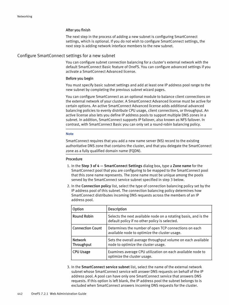
After you finish
The next step in the process of adding a new subnet is configuring SmartConnectsettings, which is optional. If you do not wish to configure SmartConnect settings, thenext step is adding network interface members to the new subnet.
Configure SmartConnect settings for a new subnetYou can configure subnet connection balancing for a cluster's external network with thedefault SmartConnect Basic feature of OneFS. You can configure advanced settings if youactivate a SmartConnect Advanced license.
Before you begin
You must specify basic subnet settings and add at least one IP address pool range to thenew subnet by completing the previous subnet wizard pages.
You can configure SmartConnect as an optional module to balance client connections onthe external network of your cluster. A SmartConnect Advanced license must be active forcertain options. An active SmartConnect Advanced license adds additional advancedbalancing policies to evenly distribute CPU usage, client connections, or throughput. Anactive license also lets you define IP address pools to support multiple DNS zones in asubnet. In addition, SmartConnect supports IP failover, also known as NFS failover. Incontrast, with SmartConnect Basic you can only set a round-robin balancing policy.
Note
SmartConnect requires that you add a new name server (NS) record to the existingauthoritative DNS zone that contains the cluster, and that you delegate the SmartConnectzone as a fully qualified domain name (FQDN).
Procedure
1. In the Step 3 of 4 — SmartConnect Settings dialog box, type a Zone name for theSmartConnect pool that you are configuring to be mapped to the SmartConnect poolthat this zone name represents. The zone name must be unique among the poolsserved by the SmartConnect service subnet specified in step 3 below.
2. In the Connection policy list, select the type of connection balancing policy set by theIP address pool of this subnet. The connection balancing policy determines howSmartConnect distributes incoming DNS requests across the members of an IPaddress pool.
Option Description
Round Robin Selects the next available node on a rotating basis, and is thedefault policy if no other policy is selected.
Connection Count Determines the number of open TCP connections on eachavailable node to optimize the cluster usage.
NetworkThroughput
Sets the overall average throughput volume on each availablenode to optimize the cluster usage.
CPU Usage Examines average CPU utilization on each available node tooptimize the cluster usage.
3. In the SmartConnect service subnet list, select the name of the external networksubnet whose SmartConnect service will answer DNS requests on behalf of the IPaddress pool. A pool can have only one SmartConnect service that answers DNSrequests. If this option is left blank, the IP address pool the subnet belongs to isexcluded when SmartConnect answers incoming DNS requests for the cluster.
Networking
442 OneFS 7.2.1 Web Administration Guide
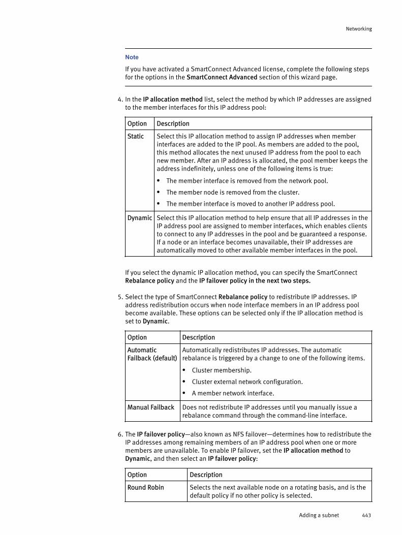
Note
If you have activated a SmartConnect Advanced license, complete the following stepsfor the options in the SmartConnect Advanced section of this wizard page.
4. In the IP allocation method list, select the method by which IP addresses are assignedto the member interfaces for this IP address pool:
Option Description
Static Select this IP allocation method to assign IP addresses when memberinterfaces are added to the IP pool. As members are added to the pool,this method allocates the next unused IP address from the pool to eachnew member. After an IP address is allocated, the pool member keeps theaddress indefinitely, unless one of the following items is true:
l The member interface is removed from the network pool.
l The member node is removed from the cluster.
l The member interface is moved to another IP address pool.
Dynamic Select this IP allocation method to help ensure that all IP addresses in theIP address pool are assigned to member interfaces, which enables clientsto connect to any IP addresses in the pool and be guaranteed a response.If a node or an interface becomes unavailable, their IP addresses areautomatically moved to other available member interfaces in the pool.
If you select the dynamic IP allocation method, you can specify the SmartConnectRebalance policy and the IP failover policy in the next two steps.
5. Select the type of SmartConnect Rebalance policy to redistribute IP addresses. IPaddress redistribution occurs when node interface members in an IP address poolbecome available. These options can be selected only if the IP allocation method isset to Dynamic.
Option Description
AutomaticFailback (default)
Automatically redistributes IP addresses. The automaticrebalance is triggered by a change to one of the following items.
l Cluster membership.
l Cluster external network configuration.
l A member network interface.
Manual Failback Does not redistribute IP addresses until you manually issue arebalance command through the command-line interface.
6. The IP failover policy—also known as NFS failover—determines how to redistribute theIP addresses among remaining members of an IP address pool when one or moremembers are unavailable. To enable IP failover, set the IP allocation method toDynamic, and then select an IP failover policy:
Option Description
Round Robin Selects the next available node on a rotating basis, and is thedefault policy if no other policy is selected.
Networking
Adding a subnet 443
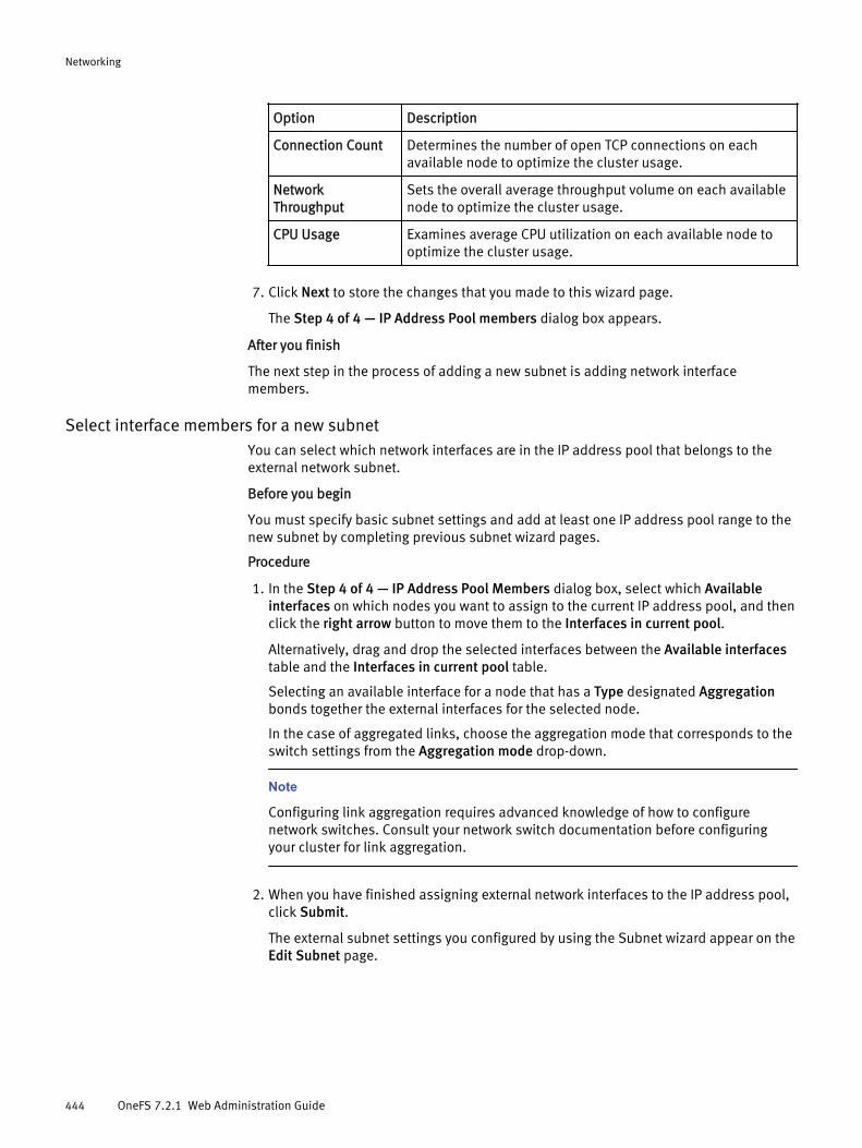
Option Description
Connection Count Determines the number of open TCP connections on eachavailable node to optimize the cluster usage.
NetworkThroughput
Sets the overall average throughput volume on each availablenode to optimize the cluster usage.
CPU Usage Examines average CPU utilization on each available node tooptimize the cluster usage.
7. Click Next to store the changes that you made to this wizard page.
The Step 4 of 4 — IP Address Pool members dialog box appears.
After you finish
The next step in the process of adding a new subnet is adding network interfacemembers.
Select interface members for a new subnetYou can select which network interfaces are in the IP address pool that belongs to theexternal network subnet.
Before you begin
You must specify basic subnet settings and add at least one IP address pool range to thenew subnet by completing previous subnet wizard pages.
Procedure
1. In the Step 4 of 4 — IP Address Pool Members dialog box, select which Availableinterfaces on which nodes you want to assign to the current IP address pool, and thenclick the right arrow button to move them to the Interfaces in current pool.
Alternatively, drag and drop the selected interfaces between the Available interfacestable and the Interfaces in current pool table.
Selecting an available interface for a node that has a Type designated Aggregationbonds together the external interfaces for the selected node.
In the case of aggregated links, choose the aggregation mode that corresponds to theswitch settings from the Aggregation mode drop-down.
Note
Configuring link aggregation requires advanced knowledge of how to configurenetwork switches. Consult your network switch documentation before configuringyour cluster for link aggregation.
2. When you have finished assigning external network interfaces to the IP address pool,click Submit.
The external subnet settings you configured by using the Subnet wizard appear on theEdit Subnet page.
Networking
444 OneFS 7.2.1 Web Administration Guide
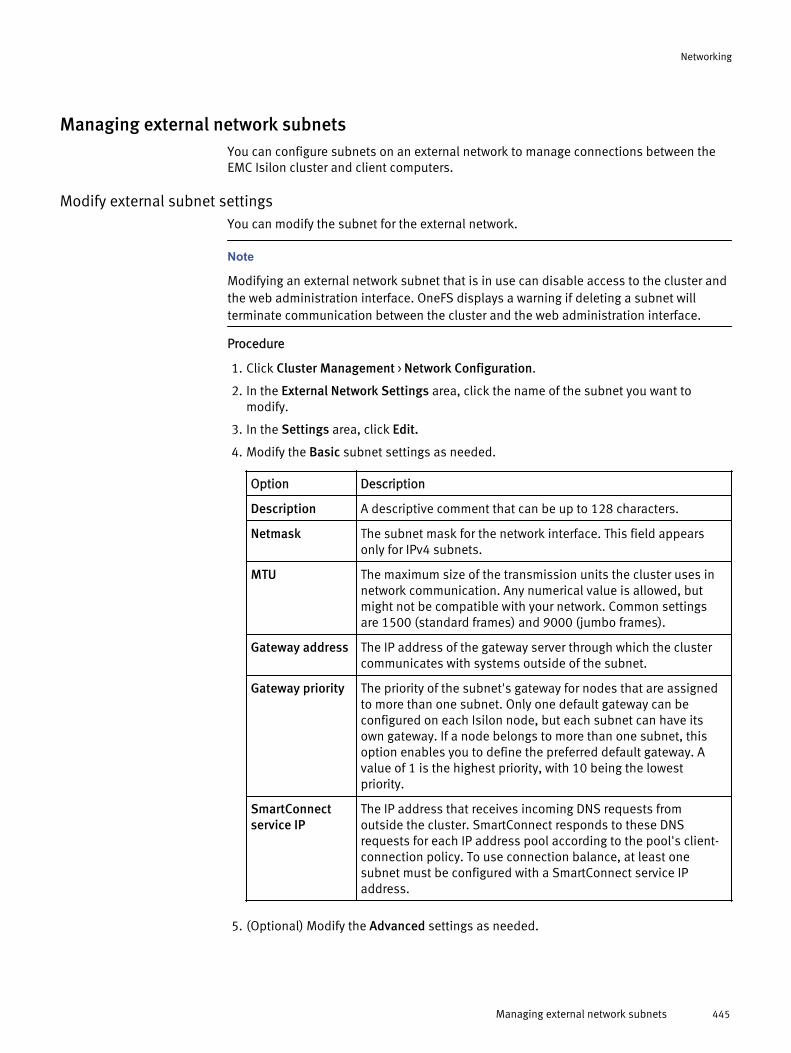
Managing external network subnetsYou can configure subnets on an external network to manage connections between theEMC Isilon cluster and client computers.
Modify external subnet settingsYou can modify the subnet for the external network.
Note
Modifying an external network subnet that is in use can disable access to the cluster andthe web administration interface. OneFS displays a warning if deleting a subnet willterminate communication between the cluster and the web administration interface.
Procedure
1. Click Cluster Management > Network Configuration.
2. In the External Network Settings area, click the name of the subnet you want tomodify.
3. In the Settings area, click Edit.
4. Modify the Basic subnet settings as needed.
Option Description
Description A descriptive comment that can be up to 128 characters.
Netmask The subnet mask for the network interface. This field appearsonly for IPv4 subnets.
MTU The maximum size of the transmission units the cluster uses innetwork communication. Any numerical value is allowed, butmight not be compatible with your network. Common settingsare 1500 (standard frames) and 9000 (jumbo frames).
Gateway address The IP address of the gateway server through which the clustercommunicates with systems outside of the subnet.
Gateway priority The priority of the subnet's gateway for nodes that are assignedto more than one subnet. Only one default gateway can beconfigured on each Isilon node, but each subnet can have itsown gateway. If a node belongs to more than one subnet, thisoption enables you to define the preferred default gateway. Avalue of 1 is the highest priority, with 10 being the lowestpriority.
SmartConnectservice IP
The IP address that receives incoming DNS requests fromoutside the cluster. SmartConnect responds to these DNSrequests for each IP address pool according to the pool's client-connection policy. To use connection balance, at least onesubnet must be configured with a SmartConnect service IPaddress.
5. (Optional) Modify the Advanced settings as needed.
Networking
Managing external network subnets 445
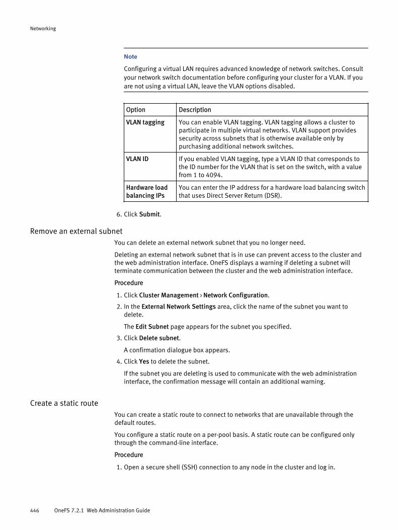
Note
Configuring a virtual LAN requires advanced knowledge of network switches. Consultyour network switch documentation before configuring your cluster for a VLAN. If youare not using a virtual LAN, leave the VLAN options disabled.
Option Description
VLAN tagging You can enable VLAN tagging. VLAN tagging allows a cluster toparticipate in multiple virtual networks. VLAN support providessecurity across subnets that is otherwise available only bypurchasing additional network switches.
VLAN ID If you enabled VLAN tagging, type a VLAN ID that corresponds tothe ID number for the VLAN that is set on the switch, with a valuefrom 1 to 4094.
Hardware loadbalancing IPs
You can enter the IP address for a hardware load balancing switchthat uses Direct Server Return (DSR).
6. Click Submit.
Remove an external subnetYou can delete an external network subnet that you no longer need.
Deleting an external network subnet that is in use can prevent access to the cluster andthe web administration interface. OneFS displays a warning if deleting a subnet willterminate communication between the cluster and the web administration interface.
Procedure
1. Click Cluster Management > Network Configuration.
2. In the External Network Settings area, click the name of the subnet you want todelete.
The Edit Subnet page appears for the subnet you specified.
3. Click Delete subnet.
A confirmation dialogue box appears.
4. Click Yes to delete the subnet.
If the subnet you are deleting is used to communicate with the web administrationinterface, the confirmation message will contain an additional warning.
Create a static routeYou can create a static route to connect to networks that are unavailable through thedefault routes.
You configure a static route on a per-pool basis. A static route can be configured onlythrough the command-line interface.
Procedure
1. Open a secure shell (SSH) connection to any node in the cluster and log in.
Networking
446 OneFS 7.2.1 Web Administration Guide
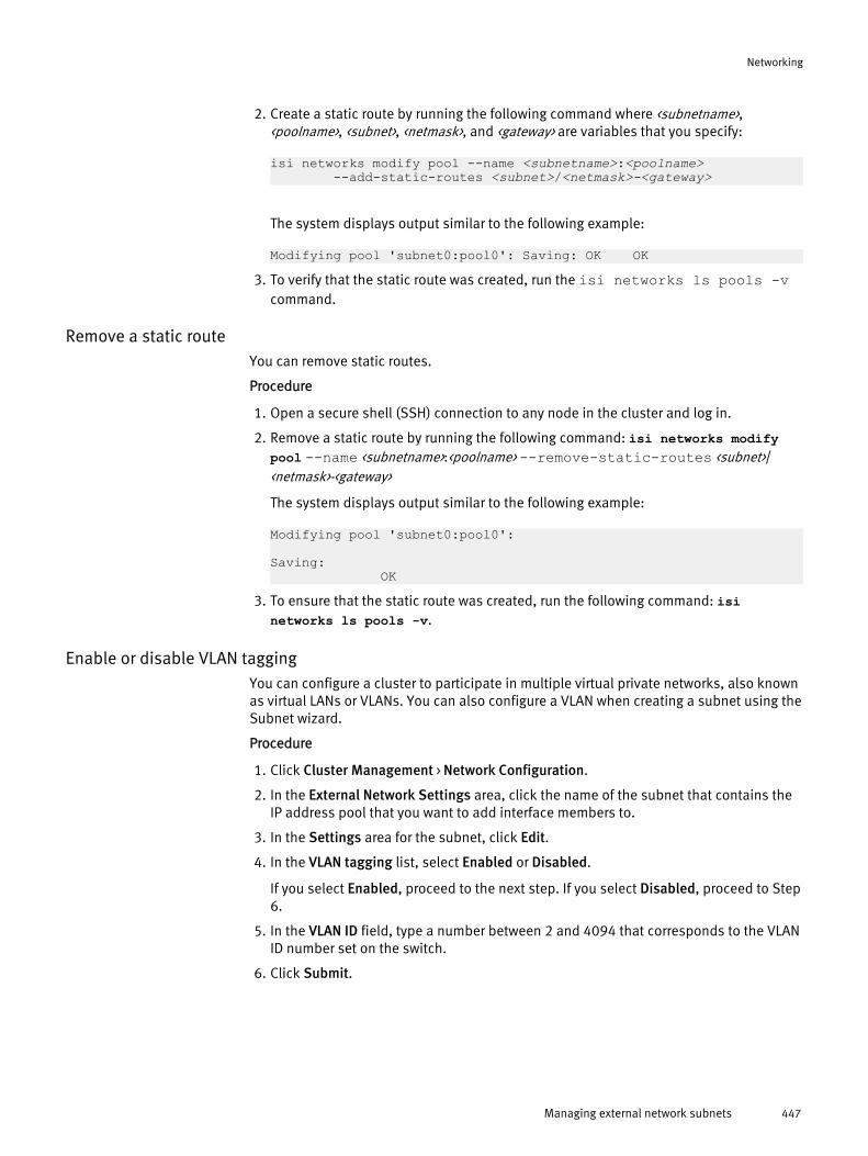
2. Create a static route by running the following command where <subnetname>,<poolname>, <subnet>, <netmask>, and <gateway> are variables that you specify:
isi networks modify pool --name <subnetname>:<poolname> --add-static-routes <subnet>/<netmask>-<gateway>
The system displays output similar to the following example:
Modifying pool 'subnet0:pool0': Saving: OK OK3. To verify that the static route was created, run the isi networks ls pools -v
command.
Remove a static routeYou can remove static routes.
Procedure
1. Open a secure shell (SSH) connection to any node in the cluster and log in.
2. Remove a static route by running the following command: isi networks modifypool --name <subnetname>:<poolname> --remove-static-routes <subnet>/<netmask>-<gateway>
The system displays output similar to the following example:
Modifying pool 'subnet0:pool0':
Saving: OK
3. To ensure that the static route was created, run the following command: isinetworks ls pools -v.
Enable or disable VLAN taggingYou can configure a cluster to participate in multiple virtual private networks, also knownas virtual LANs or VLANs. You can also configure a VLAN when creating a subnet using theSubnet wizard.
Procedure
1. Click Cluster Management > Network Configuration.
2. In the External Network Settings area, click the name of the subnet that contains theIP address pool that you want to add interface members to.
3. In the Settings area for the subnet, click Edit.
4. In the VLAN tagging list, select Enabled or Disabled.
If you select Enabled, proceed to the next step. If you select Disabled, proceed to Step6.
5. In the VLAN ID field, type a number between 2 and 4094 that corresponds to the VLANID number set on the switch.
6. Click Submit.
Networking
Managing external network subnets 447
Managing IP address poolsIP address pools allow you to manage the IP addresses clients use to connect to an EMCIsilon cluster. You can also add network interfaces to IP address pools. Each IP addresspool is associated with a subnet.
Add an IP address poolYou can add an IP address pool to a external network subnet.
Procedure
1. Click Cluster Management > Network Configuration.
2. Click the name of the subnet to which you are adding an IP address pool.
3. In the IP Address Pools area, click Add pool.
4. Specify basic settings for the new IP address pool and click Next.
5. (Optional) Specify SmartConnect settings and click Next.
6. (Optional) Add network interface members and click Submit.
Modify an IP address poolYou can use the web interface to modify IP address pool settings.
Procedure
1. Click Cluster Management > Network Configuration.
2. Click the name of the subnet containing the pool you want to modify.
3. In the Basic Settings area, click Edit for the IP address pool you want to modify.
4. Modify the address pool settings and click Submit.
Delete an IP address poolYou can use the web interface to delete IP address pool settings.
Procedure
1. Click Cluster Management > Network Configuration.
2. Click the name of the subnet containing the pool you want to delete.
3. Click Delete pool by the pool you want to delete.
Modify a SmartConnect zoneYou can modify the settings of a SmartConnect zone that you created for an externalnetwork subnet using the Subnet wizard.
Procedure
1. Click Cluster Management > Network Configuration.
2. Click the name of the external network subnet that contains the SmartConnect zoneyou want to modify.
3. In the SmartConnect settings area of the pool containing the SmartConnect settingsyou want to modify, click Edit.
4. Modify the Zone name, and then click Submit.
The SmartConnect zone should be a fully-qualified domain name (FQDN).
Networking
448 OneFS 7.2.1 Web Administration Guide

Disable a SmartConnect zoneYou can remove a SmartConnect zone from an external network subnet.
Procedure
1. Click Cluster Management > Network Configuration.
2. Click the name of the external network subnet that contains the SmartConnect zoneyou want to disable.
3. In the SmartConnect settings area for the pool containing the SmartConnect zone youwant to delete, click Edit.
4. To disable the SmartConnect zone, delete the name of the SmartConnect zone fromthe Zone name field and leave the field blank.
5. Click Submit to disable the SmartConnect zone.
Configure IP failoverYou can configure IP failover to reassign an IP address from an unavailable node to afunctional node, which enables clients to continue communicating with the cluster, evenafter a node becomes unavailable.
Procedure
1. Click Cluster Management > Network Configuration
2. In the External Network Settings area, click the name of the subnet for which youwant to set up IP failover.
3. Expand the area of the pool you want to modify and click Edit in the SmartConnectSettings area.
4. (Optional) In the Zone name field, enter a name for the zone, using no more than 128characters.
5. In the Connection Policy list, select a balancing policy:
Option Description
Round Robin Selects the next available node on a rotating basis, and is thedefault state if no other policy is selected.
Connection Count Determines the number of open TCP connections on eachavailable node to optimize the cluster usage.
Network Throughput Uses the overall average throughput volume on each availablenode to optimize the cluster usage.
CPU Usage Examines average CPU utilization on each available node tooptimize the cluster usage.
6. If you purchased a license for SmartConnect Advanced, you will also have access tothe following lists:
IP allocation method
This setting determines how IP addresses are assigned to clients. Select eitherDynamic or Static.
Networking
Managing IP address pools 449
Rebalance Policy
This setting defines the client redirection policy for when a node becomesunavailable. The IP allocation list must be set to Dynamic in order for rebalancepolicy options to be selected.
IP failover policy
This setting defines the client redirection policy when an IP address becomesunavailable.
Allocate IP addresses to accommodate new nodesYou can expand capacity by adding new nodes to your Isilon cluster.
After the hardware installation is complete, you can allocate IP addresses for a new nodeon one of the cluster's existing external network subnets, and then add the node'sexternal interfaces to the subnet's IP address pool.
You can also use network provisioning rules to automate the process of configuring theexternal network interfaces for new nodes when they are added to a cluster, although youmay still need to allocate more IP addresses for the new nodes, depending on how manyare already configured.
Procedure
1. Click Cluster Management > Network Configuration.
2. In the External Network Settings area, click the name of the subnet that contains theIP address pool that you want to allocate more IP addresses to in order toaccommodate the new nodes.
3. In the Basic settings area, click Edit.
4. Click New to add a new IP address range using the Low IP and High IP fields. or clickthe respective value in either the Low IP or High IP columns and type a new beginningor ending IP address.
5. Click Submit.
6. In the Pool members area, click Edit.
7. In the Available Interfaces table, select one or more interfaces for the newly addednode, and then click the right arrow button to move the interfaces into the Interfacesin current pool table.
8. Click Submit to assign the new node interfaces to the IP address pool.
Managing network interface membersYou can assign nodes and network interfaces to specific IP address pools.
You can also aggregate network interfaces and specify the aggregation method.
Modify the interface members of a subnetYou can use the web interface to modify interface member settings.
Procedure
1. Click Cluster Management > Network Configuration.
2. In the External Network Settings area, click the subnet containing the interfacemembers you want to modify.
Networking
450 OneFS 7.2.1 Web Administration Guide
3. Click Edit next to the Pool members area.
Remove interface members from an IP address poolYou can use the web interface to remove interface members from an IP address pool.
Procedure
1. Click Cluster Management > Network Configuration.
2. In the External Network Settings area, click the name of the subnet containing the IPaddress pool that you want to remove the interface member(s) for.
3. In the Pool members area, click Edit.
4. Remove a node's interface from the IP address pool by clicking the node's name in theInterfaces in current pool column, and then click the left arrow button. You can alsodrag and drop node interfaces between the Available Interfaces list and the Interfacesin current poolcolumn.
5. When you have finished removing node interfaces from the IP address pool, clickSubmit.
Configure NIC aggregationYou can configure cluster IP address pools to use NIC aggregation.
Before you begin
You must enable NIC aggregation on the cluster before you can enable NIC aggregationon the switch. If the cluster is configured but the switch is not configured, then the clustercan continue to communicate. If the switch is configured, but the cluster is notconfigured, the cluster cannot communicate, and you are unable to configure the clusterfor NIC aggregation.
This procedure describes how to configure network interface card (NIC) aggregation for anIP address pool belonging to an existing subnet. You can also configure NIC aggregationwhile configuring an external network subnet using the Subnet wizard.
Configuring NIC aggregation means that multiple, physical external network interfaces ona node are combined into a single logical interface. If a node has two external GigabitEthernet interfaces, both will be aggregated. On a node with both Gigabit and 10 GigabitEthernet interfaces, both types of interfaces can be aggregated, but only with interfacesof the same type. NIC aggregation cannot be used with mixed interface types.
An external interface for a node cannot be used by an IP address pool in both anaggregated configuration and an individual interface. You must remove the individualinterface for a node from the Interfaces in current pool table before configuring anaggregated NIC. Otherwise, the web administration interface displays an error messagewhen you click Submit.
Note
Configuring link aggregation requires advanced knowledge of network switches. Consultyour network switch documentation before configuring your cluster for NIC aggregation.
Procedure
1. Click Cluster Management > Network Configuration.
2. In the External Network Settings area, click the name of the subnet that contains theIP address pool that you want to add aggregated interface members to.
3. In the Pool members area, click Edit.
Networking
Managing network interface members 451
In the case of multiple IP address pools, expand the pool that you want to add theaggregated interfaces to, and then click Edit in the Pool members area.
4. In the Available interfaces table, click the aggregated interface for the node, which isindicated by a listing of AGGREGATION in the Type column.
For example, if you want to aggregate the network interface card for Node 2 of thecluster, click the interface named ext-agg, Node 2 under Available interfaces, andthen click the right-arrow button to move the aggregated interface to the Interfaces incurrent pool table.
5. From the Aggregation mode drop-down, select the appropriate aggregation mode thatcorresponds to the network switch settings.
Note
Consult your network switch documentation for supported NIC aggregation modes.
OneFS supports the following NIC aggregation modes:
Option Description
Link AggregationControl Protocol(LACP)
This method supports the IEEE 802.3ad Link AggregationControl Protocol (LACP). Balances outgoing traffic across theinterfaces based on hashed protocol header information thatincludes the source and destination address and the VLAN tag,if available. Also assembles interfaces of the same speed intogroups called Link Aggregated Groups (LAGs) and balancestraffic across the fastest LAGs. This option is the default modefor new pools.
Legacy FastEtherChannel(FEC) mode
This method aggregates network interfaces through an olderFEC driver recommended for OneFS 6.5 and earlier.
Etherchannel (FEC) This method provides static balancing on aggregated interfacesthrough the Cisco Fast EtherChannel (FEC) driver, which is foundon older Cisco switches. Capable of load balancing trafficacross Fast Ethernet links. Allows multiple physical FastEthernet links to combine into one logical channel.
Active / PassiveFailover
This method switches to the next active interface when theprimary interface becomes unavailable. Manages traffic onlythrough a primary interface. The second interface takes over thework of the first as soon as it detects an interruption incommunication.
Round-Robin Tx This method rotates connections through the nodes in a first-in,first-out sequence, handling all processes without priority.Balances outbound traffic across all active ports in theaggregated link and accepts inbound traffic on any port.
6. Click Submit.
Networking
452 OneFS 7.2.1 Web Administration Guide

NIC and LNI aggregation optionsNetwork interface card (NIC) and logical network interface (LNI) mapping options can beconfigured for aggregation.
The following list provides guidelines for interpreting the aggregation options:
l Nodes support multiple network card configurations.
l LNI numbering corresponds to the physical positioning of the NIC ports as found onthe back of the node. LNI mappings are numbered from left to right.
l Aggregated LNIs are listed in the order in which they are aggregated at the time theyare created.
l NIC names correspond to the network interface name as shown in command-lineinterface tools such as ifconfig and netstat.
LNI NIC Aggregated LNI Aggregated NIC Aggregated NIC(Legacy FECmode)
ext-1ext-2
em0em1
ext-agg = ext-1 + ext-2 lagg0 fec0
ext-1ext-2
ext-3
ext-4
em2em3
em0
em1
ext-agg = ext-1 + ext-2ext-agg-2 = ext-3 + ext-4
ext-agg-3 = ext-3 + ext-4 + ext-1 +ext-2
lagg0lagg1
lagg2
fec0fec1
fec2
ext-1ext-2
10gige-1
10gige-2
em0em1
cxgb0
cxgb1
ext-agg = ext-1 + ext-210gige-agg-1 = 10gige-1 + 10gige-2
lagg0lagg1
fec0fec1
Remove an aggregated NIC from an IP address pool
You can remove an aggregated NIC configuration from an IP address range in aSmartConnect pool if your network environment has changed. However, you must firstreplace the aggregated setting with single-NIC settings in order for the node to continuesupporting network traffic.
Procedure
1. Click Cluster Management > Network Configuration.
2. In the External Network Settings area, click the name of the subnet that contains theIP address pol with the NIC aggregation settings that you want to remove.
3. In the Pool members area, click Edit.
4. Select the name of the aggregated NIC for the node that you want to remove in theInterfaces in current pool table, and then click the left arrow button to move the nameinto the Available interfaces table.
5. Select one or more individual interfaces for the node in the Available interfaces table,and then click the right arrow button to move the interfaces into the Interfaces incurrent pool table.
6. When you have completed modifying the node interface settings, click Submit.
Networking
Managing network interface members 453
Move nodes between IP address poolsYou can move nodes between IP address pools in the event of a network reconfigurationor installation of a new network switch.
The process of moving nodes between IP address pools involves creating a new IPaddress pool and then assigning it to the nodes so that they are temporarily servicingmultiple subnets. After testing that the new IP address pool is working correctly, the oldIP address pool can safely be deleted.
Procedure
1. Create a new IP address pool with the interfaces belonging to the nodes you want tomove.
2. Verify that the new IP address pool functions properly by connecting to the nodes youwant to move with IP addresses from the new pool.
3. Delete the old IP address pool.
Reassign a node to another external subnetYou can move a node interface to a different subnet.
Nodes can be reassigned to other subnets.
Procedure
1. Click Cluster Management > Network Configuration.
2. In the External Settings area, click the subnet containing the node that you want tomodify.
3. In the IP Address Pools area, click Edit next to the Pool members area.
4. Reassign the interface members that you want to move by dragging and droppingthem from one column to other, or by clicking on an interface member and using theleft arrow and right arrow buttons.
Configure DNS settingsYou can configure the domain name servers (DNS) and DNS search list to resolve hostnames for the EMC Isilon cluster.
Procedure
1. Click Cluster Management > Networking Configuration.
2. In the DNS Settings area, click Edit.
3. In the Domain name server(s) field, enter up to three domain name server IPaddresses. You can specify domain name server addresses in IPv4 or IPv6 format.
4. In the DNS search list field, enter up to six DNS search suffixes. DNS search suffixesare appended to unqualified host names .
5. (Optional) In the DNS resolver options field, enter advanced DNS configurationoptions.
Note
DNS resolver options are described in the /etc/resolv.conf file. Setting DNS
resolver options is not recommended. Most clusters do not need DNS resolver optionsand setting them may change how OneFS performs DNS lookups.
Networking
454 OneFS 7.2.1 Web Administration Guide
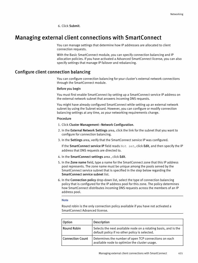
6. Click Submit.
Managing external client connections with SmartConnectYou can manage settings that determine how IP addresses are allocated to clientconnection requests.
With the Basic SmartConnect module, you can specify connection balancing and IPallocation policies. If you have activated a Advanced SmartConnect license, you can alsospecify settings that manage IP failover and rebalancing.
Configure client connection balancingYou can configure connection balancing for your cluster's external network connectionsthrough the SmartConnect module.
Before you begin
You must first enable SmartConnect by setting up a SmartConnect service IP address onthe external network subnet that answers incoming DNS requests.
You might have already configured SmartConnect while setting up an external networksubnet by using the Subnet wizard. However, you can configure or modify connectionbalancing settings at any time, as your networking requirements change.
Procedure
1. Click Cluster Management > Network Configuration.
2. In the External Network Settings area, click the link for the subnet that you want toconfigure for connection balancing.
3. In the Settings area, verify that the SmartConnect service IP was configured.
If the SmartConnect service IP field reads Not set, click Edit, and then specify the IPaddress that DNS requests are directed to.
4. In the SmartConnect settings area , click Edit.
5. In the Zone name field, type a name for the SmartConnect zone that this IP addresspool represents. The zone name must be unique among the pools served by theSmartConnect service subnet that is specified in the step below regarding theSmartConnect service subnet list.
6. In the Connection policy drop-down list, select the type of connection balancingpolicy that is configured for the IP address pool for this zone. The policy determineshow SmartConnect distributes incoming DNS requests across the members of an IPaddress pool.
Note
Round robin is the only connection policy available if you have not activated aSmartConnect Advanced license.
Option Description
Round Robin Selects the next available node on a rotating basis, and is thedefault policy if no other policy is selected.
Connection Count Determines the number of open TCP connections on eachavailable node to optimize the cluster usage.
Networking
Managing external client connections with SmartConnect 455
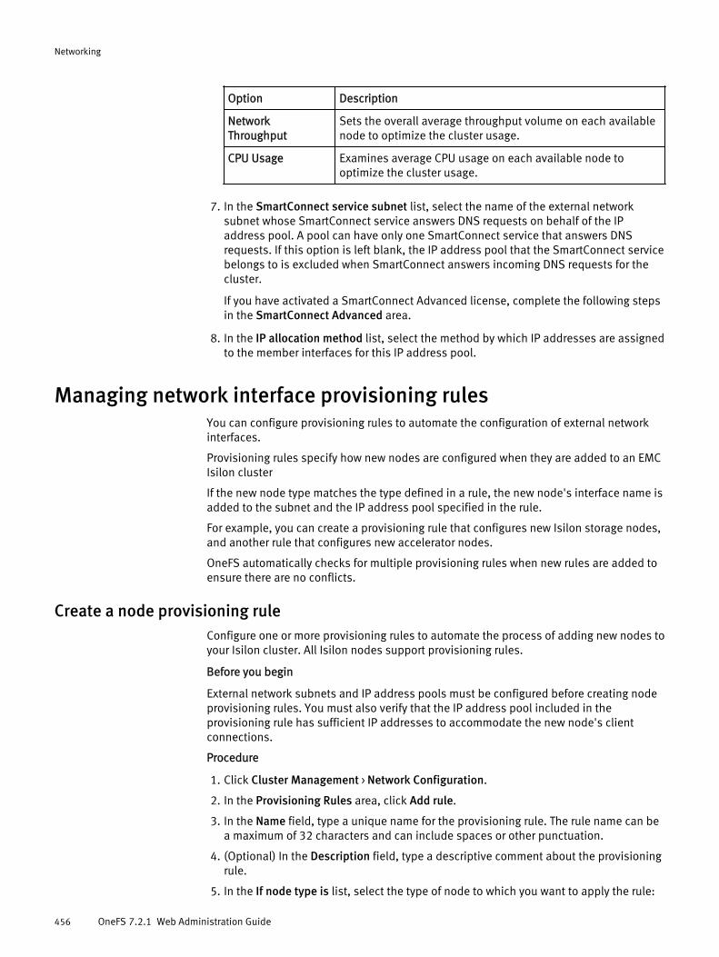
Option Description
NetworkThroughput
Sets the overall average throughput volume on each availablenode to optimize the cluster usage.
CPU Usage Examines average CPU usage on each available node tooptimize the cluster usage.
7. In the SmartConnect service subnet list, select the name of the external networksubnet whose SmartConnect service answers DNS requests on behalf of the IPaddress pool. A pool can have only one SmartConnect service that answers DNSrequests. If this option is left blank, the IP address pool that the SmartConnect servicebelongs to is excluded when SmartConnect answers incoming DNS requests for thecluster.
If you have activated a SmartConnect Advanced license, complete the following stepsin the SmartConnect Advanced area.
8. In the IP allocation method list, select the method by which IP addresses are assignedto the member interfaces for this IP address pool.
Managing network interface provisioning rulesYou can configure provisioning rules to automate the configuration of external networkinterfaces.
Provisioning rules specify how new nodes are configured when they are added to an EMCIsilon cluster
If the new node type matches the type defined in a rule, the new node's interface name isadded to the subnet and the IP address pool specified in the rule.
For example, you can create a provisioning rule that configures new Isilon storage nodes,and another rule that configures new accelerator nodes.
OneFS automatically checks for multiple provisioning rules when new rules are added toensure there are no conflicts.
Create a node provisioning ruleConfigure one or more provisioning rules to automate the process of adding new nodes toyour Isilon cluster. All Isilon nodes support provisioning rules.
Before you begin
External network subnets and IP address pools must be configured before creating nodeprovisioning rules. You must also verify that the IP address pool included in theprovisioning rule has sufficient IP addresses to accommodate the new node's clientconnections.
Procedure
1. Click Cluster Management > Network Configuration.
2. In the Provisioning Rules area, click Add rule.
3. In the Name field, type a unique name for the provisioning rule. The rule name can bea maximum of 32 characters and can include spaces or other punctuation.
4. (Optional) In the Description field, type a descriptive comment about the provisioningrule.
5. In the If node type is list, select the type of node to which you want to apply the rule:
Networking
456 OneFS 7.2.1 Web Administration Guide
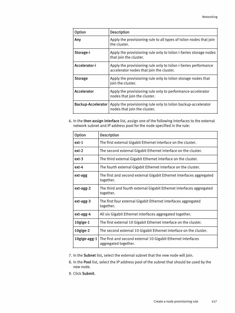
Option Description
Any Apply the provisioning rule to all types of Isilon nodes that jointhe cluster.
Storage-i Apply the provisioning rule only to Isilon i-Series storage nodesthat join the cluster.
Accelerator-i Apply the provisioning rule only to Isilon i-Series performanceaccelerator nodes that join the cluster.
Storage Apply the provisioning rule only to Isilon storage nodes thatjoin the cluster.
Accelerator Apply the provisioning rule only to performance-acceleratornodes that join the cluster.
Backup-Accelerator Apply the provisioning rule only to Isilon backup-acceleratornodes that join the cluster.
6. In the then assign interface list, assign one of the following interfaces to the externalnetwork subnet and IP address pool for the node specified in the rule:
Option Description
ext-1 The first external Gigabit Ethernet interface on the cluster.
ext-2 The second external Gigabit Ethernet interface on the cluster.
ext-3 The third external Gigabit Ethernet interface on the cluster.
ext-4 The fourth external Gigabit Ethernet interface on the cluster.
ext-agg The first and second external Gigabit Ethernet interfaces aggregatedtogether.
ext-agg-2 The third and fourth external Gigabit Ethernet interfaces aggregatedtogether.
ext-agg-3 The first four external Gigabit Ethernet interfaces aggregatedtogether.
ext-agg-4 All six Gigabit Ethernet interfaces aggregated together.
10gige-1 The first external 10 Gigabit Ethernet interface on the cluster.
10gige-2 The second external 10 Gigabit Ethernet interface on the cluster.
10gige-agg-1 The first and second external 10 Gigabit Ethernet interfacesaggregated together.
7. In the Subnet list, select the external subnet that the new node will join.
8. In the Pool list, select the IP address pool of the subnet that should be used by thenew node.
9. Click Submit.
Networking
Create a node provisioning rule 457

Modify a node provisioning ruleYou can modify node provisioning rules.
Procedure
1. Click Cluster Configuration > Network Configuration.
2. In the Provisioning Rules area, click the name of the rule you want to modify.
3. Modify the provisioning rule settings as needed.
4. Click Submit.
Delete a node provisioning ruleYou can delete a provisioning rule that is no longer necessary.
Procedure
1. Click Cluster Management > Network Configuration.
2. In the Provisioning Rules area, click Delete next to the rule you want to delete.
A confirmation dialog box appears.
3. Click Yes to delete the rule, or click No to keep the rule.
Managing routing optionsYou can control the direction of outgoing client traffic through source-based routing orstatic route configuration.
Enable or disable source-based routingYou can enable source-based routing to ensure that outgoing client traffic is routed to thegateway of the source IP address in the packet header. If you disable source-basedrouting, outgoing traffic is destination-based or it follows static routes.
Before you begin
Source-based routing rules are prioritized over static routes. You can check if there arestatic routes configured in any IP address pools by running the following command:
isi networks list pools -v
Source-based routing is enabled or disabled on the entire EMC Isilon cluster andsupports only the IPv4 protocol.Enabling and disabling source-based routing is only supported through the command-line interface.
Procedure
1. Enable source-based routing by running the following command:
isi networks sbr enable
2. Disable source-based routing by running the following command:
isi networks sbr disable
Networking
458 OneFS 7.2.1 Web Administration Guide
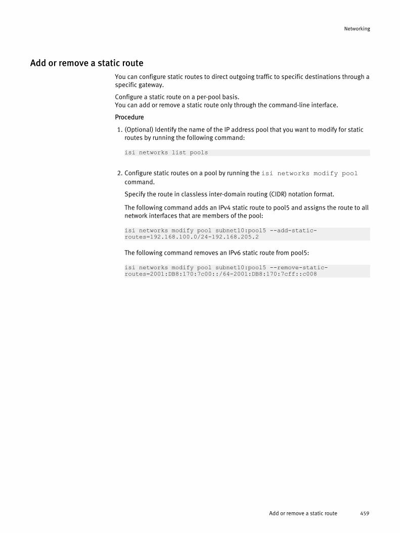
Add or remove a static routeYou can configure static routes to direct outgoing traffic to specific destinations through aspecific gateway.
Configure a static route on a per-pool basis.You can add or remove a static route only through the command-line interface.
Procedure
1. (Optional) Identify the name of the IP address pool that you want to modify for staticroutes by running the following command:
isi networks list pools
2. Configure static routes on a pool by running the isi networks modify poolcommand.
Specify the route in classless inter-domain routing (CIDR) notation format.
The following command adds an IPv4 static route to pool5 and assigns the route to allnetwork interfaces that are members of the pool:
isi networks modify pool subnet10:pool5 --add-static-routes=192.168.100.0/24-192.168.205.2
The following command removes an IPv6 static route from pool5:
isi networks modify pool subnet10:pool5 --remove-static-routes=2001:DB8:170:7c00::/64-2001:DB8:170:7cff::c008
Networking
Add or remove a static route 459

Networking
460 OneFS 7.2.1 Web Administration Guide
CHAPTER 24
Hadoop
This section contains the following topics:
l Hadoop overview................................................................................................ 462l Hadoop architecture............................................................................................462l How Hadoop is implemented on OneFS...............................................................463l Hadoop distributions supported by OneFS.......................................................... 463l WebHDFS............................................................................................................ 464l Secure impersonation......................................................................................... 464l Ambari agent.......................................................................................................465l Virtual HDFS racks...............................................................................................466l HDFS implementation considerations..................................................................466l Managing the HDFS service................................................................................. 468l Managing HDFS access zone settings..................................................................470l Configuring secure impersonation.......................................................................474l Managing virtual HDFS racks............................................................................... 476
Hadoop 461

Hadoop overviewHadoop is an open-source platform that runs analytics on large sets of data across adistributed file system.
In a Hadoop implementation on an EMC Isilon cluster, OneFS acts as the distributed filesystem and HDFS is supported as a native protocol. Clients from a Hadoop clusterconnect to the Isilon cluster through the HDFS protocol to manage and process data.
Hadoop support on the cluster requires you to activate an HDFS license. To obtain alicense, contact your EMC Isilon sales representative.
Hadoop architectureHadoop consists of a compute layer and a storage layer.
In a typical Hadoop implementation, both layers exist on the same cluster.
Hadoop compute layerMapReduce 2.0 (YARN) is the task processing engine of the Hadoop compute layer.
MapReduce runs a variety of jobs (also known as applications), or queries, on large setsof data and pulls information out. MapReduce relies on the following key components:
ResourceManager
Global authority that allocates resources (such as CPU, memory, disk, network) toNodeManagers, and schedules jobs based on their resource requirements.
ApplicationMaster
Per-job component that negotiates job resources from the ResourceManager andtracks job status.
NodeManager
Per-node component that launches jobs and monitors job resource consumption.
HDFS storage layerThe storage layer is known as the Hadoop distributed file system (HDFS).
The storage layer contains the data accessed and processed by the compute layer. HDFSrelies on two key components:
DataNode
Node that stores data and serves read and write requests as directed by theNameNode component.
NameNode
Node that stores in-memory maps of every file, including information about whichDataNode the file resides on and the location of the file on the DataNode.
A typical Hadoop implementation contains one NameNode that acts as a master androutes requests for data access to the proper DataNode.
Hadoop
462 OneFS 7.2.1 Web Administration Guide

How Hadoop is implemented on OneFSIn a Hadoop implementation on the EMC Isilon cluster, data is stored on OneFS. HDFS issupported as a protocol, which is used by Hadoop compute clients to access data.
A Hadoop implementation with OneFS differs from a typical Hadoop implementation inthe following ways:
l The compute and storage layers are on separate clusters instead of the same cluster.
l Instead of storing data within a Hadoop distributed file system, the storage layerfunctionality is fulfilled by OneFS on an EMC Isilon cluster. Nodes on the Isilon clusterfunction as both a NameNode and a DataNode.
l The compute layer is established on a Hadoop compute cluster that is separate fromthe Isilon cluster. MapReduce and its components are installed on the Hadoopcompute cluster only.
l Rather than a storage layer, HDFS is implemented on OneFS as a native, lightweightprotocol layer between the Isilon cluster and the Hadoop compute cluster. Clientsfrom the Hadoop compute cluster authenticate over HDFS to access data on the Isiloncluster.
l In addition to HDFS, clients from the Hadoop compute cluster can connect to theIsilon cluster over any protocol that OneFS supports such as NFS, SMB, FTP, andHTTP.
l Hadoop compute clients can connect to any node on the Isilon cluster that functionsas a NameNode instead of being routed by a single NameNode.
Hadoop distributions supported by OneFSYou can run most of the common Hadoop distributions with the EMC Isilon cluster.
OneFS supports the following Hadoop distributions:
Hadoopdistribution
Versions supported
Cloudera CDH l 3 (Updates 2–5)
l 4.2
l 5.0
l 5.1
l 5.2
l 5.3
l 5.4
ClouderaManager
l 4.0
l 5.2
Greenplum GPHD l 1.1
l 1.2
HAWQ l 1.1.0.1
Hadoop
How Hadoop is implemented on OneFS 463
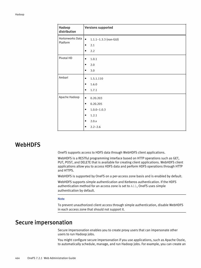
Hadoopdistribution
Versions supported
Hortonworks DataPlatform
l 1.1.1–1.3.3 (non-GUI)
l 2.1
l 2.2
Pivotal HD l 1.0.1
l 2.0
l 3.0
Ambari l 1.5.1.110
l 1.6.0
l 1.7.1
Apache Hadoop l 0.20.203
l 0.20.205
l 1.0.0–1.0.3
l 1.2.1
l 2.0.x
l 2.2–2.6
WebHDFSOneFS supports access to HDFS data through WebHDFS client applications.
WebHDFS is a RESTful programming interface based on HTTP operations such as GET,PUT, POST, and DELETE that is available for creating client applications. WebHDFS clientapplications allow you to access HDFS data and perform HDFS operations through HTTPand HTTPS.
WebHDFS is supported by OneFS on a per-access zone basis and is enabled by default.
WebHDFS supports simple authentication and Kerberos authentication. If the HDFSauthentication method for an access zone is set to All, OneFS uses simpleauthentication by default.
Note
To prevent unauthorized client access through simple authentication, disable WebHDFSin each access zone that should not support it.
Secure impersonationSecure impersonation enables you to create proxy users that can impersonate otherusers to run Hadoop jobs.
You might configure secure impersonation if you use applications, such as Apache Oozie,to automatically schedule, manage, and run Hadoop jobs. For example, you can create an
Hadoop
464 OneFS 7.2.1 Web Administration Guide

Oozie proxy user that securely impersonates a user called HadoopAdmin, which allowsthe Oozie user to request that Hadoop jobs be performed by the HadoopAdmin user.
You configure proxy users for secure impersonation on a per–zone basis, and users orgroups of users that you assign as members to the proxy user must be from the sameaccess zone. A member can be one or more of the following identity types:
l User specified by user name or UID
l Group of users specified by group name or GID
l User, group, machine, or account specified by SID
l Well-known user specified by name
If the proxy user does not present valid credentials or if a proxy user member does notexist on the cluster, access is denied. The proxy user can only access files and sub-directories located in the HDFS root directory of the access zone. It is recommended thatyou limit the members that the proxy user can impersonate to users that have access onlyto the data the proxy user needs.
Ambari agentThe Ambari client/server framework is a third-party tool that enables you to configure,manage, and monitor a Hadoop cluster through a browser-based interface. The OneFSAmbari agent allows you to monitor the status of HDFS services on the EMC Isilon clusterthrough the Ambari interface.
The Ambari agent is configured per access zone; you can configure the OneFS Ambariagent in any access zone that contains HDFS data. To start an Ambari agent in an accesszone, you must specify the IPv4 address of the external Ambari server and the address ofa NameNode that acts as the point of contact for the access zone.
The external Ambari server receives communications from the OneFS Ambari agent. Oncethe Ambari agent assigned to the access zone registers with the Ambari server, the agentprovides a heartbeat status at regular intervals. The OneFS Ambari agent does notprovide metrics or alerts to the Ambari server. The external Ambari server must bespecified by a resolvable hostname, FQDN, or IPv4 address and must be assigned to anaccess zone.
The NameNode is the designated point of contact in an access zone that Hadoop servicesmanaged through the Ambari interface should connect through. For example, if youmanage services such as YARN or Oozie through the Ambari interface, the services willconnect to the access zone through the specified NameNode. The Ambari agentcommunicates the location of the designated NameNode to the Ambari server, and to theAmbari interface, the NameNode represents the access zone. If you change thedesignated NameNode address, the Ambari agent will inform the Ambari server. TheNameNode must be a resolvable SmartConnect zone name or an IP address from the IPaddress pool associated with the access zone.
Note
The specified NameNode value maps to the NameNode, secondary NameNode, andDataNode components on the Ambari interface.
The OneFS Ambari agent is based on the Apache Ambari framework and is compatiblewith Ambari server versions 1.5.1.110, 1.6.0., and 1.7.1.
Hadoop
Ambari agent 465
Virtual HDFS racksYou can create a virtual HDFS rack of nodes on the EMC Isilon cluster to optimizeperformance and reduce latency when accessing HDFS data.
A virtual HDFS rack enables you to specify a pool of preferred HDFS nodes on the EMCIsilon cluster and specify an associated pool of Hadoop compute clients.
When a Hadoop compute client from the defined pool connects to the cluster, OneFSreturns at least two IP addresses from the pool of preferred HDFS nodes.
Virtual HDFS racks allow you to fine-tune client connectivity by directing Hadoop computeclients to go through quicker, less-busy switches or to faster nodes, depending on yournetwork topology.
HDFS implementation considerationsImplementing HDFS requires you to take other areas of OneFS into consideration toensure successful connections and access to HDFS data.
HDFS directories and Hadoop user accountsBefore implementing Hadoop, ensure that the directories and user accounts that you willneed for Hadoop are configured on the EMC Isilon cluster.
When you set up directories, files, accounts, and permissions, ensure that they have thecorrect permissions so that Hadoop clients and applications can access the directoriesand files. Directories and permissions will vary by Hadoop distribution, environment,requirements, and security policies.
You must also ensure that the user accounts that your Hadoop distribution requires areconfigured on the Isilon cluster on a per-zone basis. The user accounts that you need andthe associated owner and group settings vary by distribution, requirements, and securitypolicies. The profiles of the accounts, including UIDs and GIDS, on the Isilon clustershould match those of the accounts on your Hadoop compute clients.
OneFS must be able to look up a local Hadoop user by name. If there are no directoryservices, such as Active Directory or LDAP, that can perform a user lookup, you mustcreate a local Hadoop user. If directory services are available, a local user account is notrequired.
HDFS settings in access zonesSome HDFS attributes must be configured for each access zone on the EMC Isilon cluster.
You configure one HDFS root directory for each access zone. When a Hadoop computeclient connects to the cluster, the user can access all files and sub-directories in thespecified root directory. Unlike NFS mounts or SMB shares, clients connecting to thecluster through HDFS cannot be given access to individual folders within the rootdirectory. The default HDFS directory is /ifs.
If you have multiple Hadoop workflows that require separate sets of data, you can createmultiple access zones and configure a unique HDFS root directory for each zone.
You configure the authentication method for each access zone. HDFS supports simpleauthentication, Kerberos authentication, or both. When a Hadoop compute clientconnects to an access zone on the Isilon cluster, the client must authenticate with the
Hadoop
466 OneFS 7.2.1 Web Administration Guide
method specified for that access zone. By default, HDFS accepts both simple andKerberos authentication.
Proxy users are configured on a per-zone basis. Members assigned to the proxy user mustbelong to the same access zone.
When HDFS is licensed, the HDFS service is enabled on the entire cluster. You cannotdisable HDFS on a per-access zone basis. If you create multiple access zones, you mustconfigure HDFS settings for each zone that you want Hadoop compute clients to accessthrough HDFS.
HDFS and SmartConnectYou can set up a SmartConnect zone for connections from Hadoop compute clients.
SmartConnect is a module that specifies how the DNS server on the EMC Isilon clusterhandles connection requests from clients.
Each SmartConnect zone represents a specific pool of IP addresses. When you associatea SmartConnect zone with an access zone, OneFS only allows Hadoop clients connectingthrough the IP addresses in the SmartConnect zone to reach the HDFS data in the accesszone. A root HDFS directory is specified for each access zone. This configuration isolatesdata within access zones and allows you to restrict client access to the data.
A SmartConnect zone evenly distributes NameNode requests from Hadoop computeclients across the access zone. When a Hadoop compute client makes an initial DNSrequest to connect to the SmartConnect zone, the Hadoop client is routed to an Isilonnode that serves as a NameNode. Subsequent requests from the Hadoop compute clientgo the same node. When a second Hadoop client makes a DNS request for theSmartConnect zone, SmartConnect balances the traffic and routes the client connectionto a different node than that used by the previous Hadoop compute client.
If you create a SmartConnect zone, you must add a new name server (NS) record as adelegated domain to the authoritative DNS zone that contains the Isilon cluster. On theHadoop compute cluster, you must add the name of the DNS entry of the SmartConnectzone to the core-site.xml file so that your Hadoop compute clients connect to aNameNode with the DNS name of the zone.
SmartConnect is discussed in further detail in the Networking section of this guide.
Implementing Hadoop with OneFSTo support Hadoop on the EMC Isilon cluster, you must configure HDFS on the Isiloncluster to communicate with a Hadoop cluster.
The process for configuring HDFS on the Isilon cluster is summarized in the following list:
l Activate a license for HDFS. When a license is activated, the HDFS service is enabledby default.
l Create directories on the cluster that will be set as HDFS root directories.
l Create a SmartConnect zone for balancing connections from Hadoop compute clients.
l Create local Hadoop users in access zones that do not have directory services suchas Active Directory or LDAP.
l Set the HDFS root directory in each access zone that supports HDFS connections.
l Enable or disable WebHDFS in each access zone.
l Set an authentication method in each access zone that supports HDFS connections.
l Configure HDFS service settings on the cluster.
Hadoop
HDFS and SmartConnect 467

l Configure proxy users for secure impersonation.
l Configure virtual HDFS racks.
Managing the HDFS serviceYou can configure HDFS service settings on the EMC Isilon cluster to improve performancefor HDFS workflows.
Configure HDFS service settingsYou can configure HDFS service settings to improve performance for HDFS workflows.
HDFS service settings can be configured only through the command-line interface.
Procedure
1. Open a secure shell (SSH) connection to any node in the cluster and then log in.
2. Run the isi hdfs settings modify command.
The following example command sets the block size to 1 GB:
isi hdfs settings modify --default-block-size=1G
You must specify the block size in bytes. Suffixes K, M, and G are allowed.
The following example command sets the checksum type to crc32:
isi hdfs settings modify --default-checksum-type=crc32
The following example command sets the log level to CRIT:
isi hdfs settings modify --server-log-level=CRIT
The following example command sets the number of server threads to 32:
isi hdfs settings modify --server-threads=32
HDFS service settingsHDFS service settings affect the performance of HDFS workflows.
You can configure the following HDFS service settings:
Setting Description
Block size The HDFS block size setting on the EMC cluster determines how the HDFSservice returns data upon read requests from Hadoop compute client.You can modify the HDFS block size on the cluster to increase the block sizefrom the default of 64 MB up to 128 MB. Increasing the block size enables theIsilon cluster nodes to read and write HDFS data in larger blocks and optimizeperformance for most use cases.
The Hadoop cluster maintains a different block size that determines how aHadoop compute client writes a block of file data to the Isilon cluster. Theoptimal block size depends on your data, how you process your data, and otherfactors. You can configure the block size on the Hadoop cluster in the hdfs-site.xml configuration file in the dfs.block.size property.
Hadoop
468 OneFS 7.2.1 Web Administration Guide

Setting Description
Checksum type The HDFS service sends the checksum type to Hadoop compute clients, but itdoes not send any checksum data, regardless of the checksum type. Thedefault checksum type is set to None. If you Hadoop distribution requires a
checksum type other than None to the client, you can set the checksum type to
CRC32 or CRC32C.
Service threads The HDFS service generates multiple threads to handle HDFS traffic from EMCIsilon nodes.By default, the service thread value is set to auto, which calculates the thread
count by multiplying the number of cores on a node by eight and adding aminimum threshold of thirteen. It generates a maximum of 96 threads on anode.
To support a large system of Hadoop compute clients, you might need toincrease the number of threads. If you are distributing HDFS traffic across all ofthe nodes in an Isilon cluster through a SmartConnect zone, the total number ofHDFS service threads should equal at least half of the total number of maps andreduces on the Hadoop compute cluster. The maximum thread count is 256 pernode.
Logging level The HDFS service supports the following logging levels:
l Emergency—panic conditions broadcast to all users
l Alert—conditions that must be corrected immediately, such as a corruptsystem database
l Critical—critical conditions, such as a hard device error
l Error—general errors
l Notice—conditions that are not errors, but might require special handling
l Information—information messages that do not require action
l Debug—information typically useful only when debugging a program
View HDFS service settingsYou can view configuration details for the HDFS service.
HDFS service settings can be viewed only through the command-line interface.
Procedure
1. Open a secure shell (SSH) connection to any node in the cluster and then log in.
2. Run the isi hdfs settings view command.
The system displays output similar to the following example:
Default Block Size: 64MDefault Checksum Type: noneServer Log Level: critServer Threads: auto
Hadoop
View HDFS service settings 469
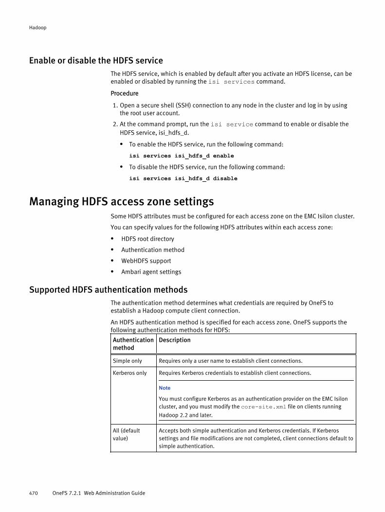
Enable or disable the HDFS serviceThe HDFS service, which is enabled by default after you activate an HDFS license, can beenabled or disabled by running the isi services command.
Procedure
1. Open a secure shell (SSH) connection to any node in the cluster and log in by usingthe root user account.
2. At the command prompt, run the isi service command to enable or disable theHDFS service, isi_hdfs_d.
l To enable the HDFS service, run the following command:
isi services isi_hdfs_d enablel To disable the HDFS service, run the following command:
isi services isi_hdfs_d disable
Managing HDFS access zone settingsSome HDFS attributes must be configured for each access zone on the EMC Isilon cluster.
You can specify values for the following HDFS attributes within each access zone:
l HDFS root directory
l Authentication method
l WebHDFS support
l Ambari agent settings
Supported HDFS authentication methodsThe authentication method determines what credentials are required by OneFS toestablish a Hadoop compute client connection.
An HDFS authentication method is specified for each access zone. OneFS supports thefollowing authentication methods for HDFS:
Authenticationmethod
Description
Simple only Requires only a user name to establish client connections.
Kerberos only Requires Kerberos credentials to establish client connections.
Note
You must configure Kerberos as an authentication provider on the EMC Isiloncluster, and you must modify the core-site.xml file on clients running
Hadoop 2.2 and later.
All (defaultvalue)
Accepts both simple authentication and Kerberos credentials. If Kerberossettings and file modifications are not completed, client connections default tosimple authentication.
Hadoop
470 OneFS 7.2.1 Web Administration Guide
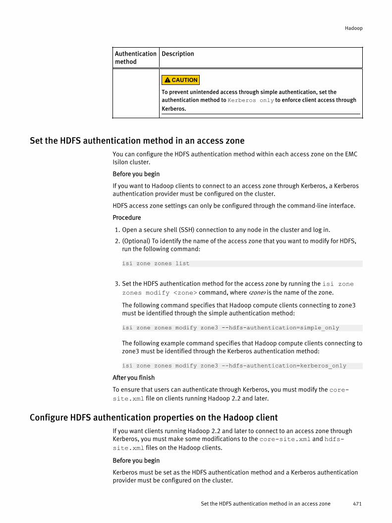
Authenticationmethod
Description
CAUTION
To prevent unintended access through simple authentication, set theauthentication method to Kerberos only to enforce client access through
Kerberos.
Set the HDFS authentication method in an access zoneYou can configure the HDFS authentication method within each access zone on the EMCIsilon cluster.
Before you begin
If you want to Hadoop clients to connect to an access zone through Kerberos, a Kerberosauthentication provider must be configured on the cluster.
HDFS access zone settings can only be configured through the command-line interface.
Procedure
1. Open a secure shell (SSH) connection to any node in the cluster and log in.
2. (Optional) To identify the name of the access zone that you want to modify for HDFS,run the following command:
isi zone zones list
3. Set the HDFS authentication method for the access zone by running the isi zonezones modify <zone> command, where <zone> is the name of the zone.
The following command specifies that Hadoop compute clients connecting to zone3must be identified through the simple authentication method:
isi zone zones modify zone3 --hdfs-authentication=simple_only
The following example command specifies that Hadoop compute clients connecting tozone3 must be identified through the Kerberos authentication method:
isi zone zones modify zone3 --hdfs-authentication=kerberos_only
After you finish
To ensure that users can authenticate through Kerberos, you must modify the core-site.xml file on clients running Hadoop 2.2 and later.
Configure HDFS authentication properties on the Hadoop clientIf you want clients running Hadoop 2.2 and later to connect to an access zone throughKerberos, you must make some modifications to the core-site.xml and hdfs-site.xml files on the Hadoop clients.
Before you begin
Kerberos must be set as the HDFS authentication method and a Kerberos authenticationprovider must be configured on the cluster.
Hadoop
Set the HDFS authentication method in an access zone 471
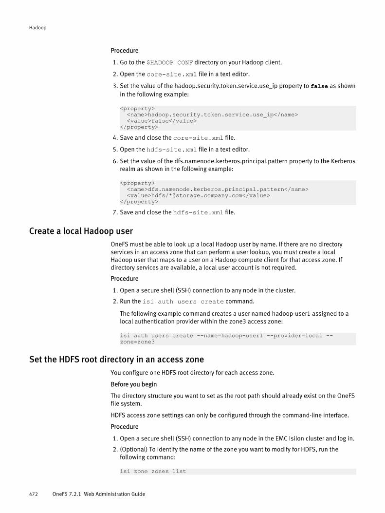
Procedure
1. Go to the $HADOOP_CONF directory on your Hadoop client.
2. Open the core-site.xml file in a text editor.
3. Set the value of the hadoop.security.token.service.use_ip property to false as shownin the following example:
<property> <name>hadoop.security.token.service.use_ip</name> <value>false</value> </property>
4. Save and close the core-site.xml file.
5. Open the hdfs-site.xml file in a text editor.
6. Set the value of the dfs.namenode.kerberos.principal.pattern property to the Kerberosrealm as shown in the following example:
<property> <name>dfs.namenode.kerberos.principal.pattern</name> <value>hdfs/*@storage.company.com</value> </property>
7. Save and close the hdfs-site.xml file.
Create a local Hadoop userOneFS must be able to look up a local Hadoop user by name. If there are no directoryservices in an access zone that can perform a user lookup, you must create a localHadoop user that maps to a user on a Hadoop compute client for that access zone. Ifdirectory services are available, a local user account is not required.
Procedure
1. Open a secure shell (SSH) connection to any node in the cluster.
2. Run the isi auth users create command.
The following example command creates a user named hadoop-user1 assigned to alocal authentication provider within the zone3 access zone:
isi auth users create --name=hadoop-user1 --provider=local --zone=zone3
Set the HDFS root directory in an access zoneYou configure one HDFS root directory for each access zone.
Before you begin
The directory structure you want to set as the root path should already exist on the OneFSfile system.
HDFS access zone settings can only be configured through the command-line interface.
Procedure
1. Open a secure shell (SSH) connection to any node in the EMC Isilon cluster and log in.
2. (Optional) To identify the name of the zone you want to modify for HDFS, run thefollowing command:
isi zone zones list
Hadoop
472 OneFS 7.2.1 Web Administration Guide
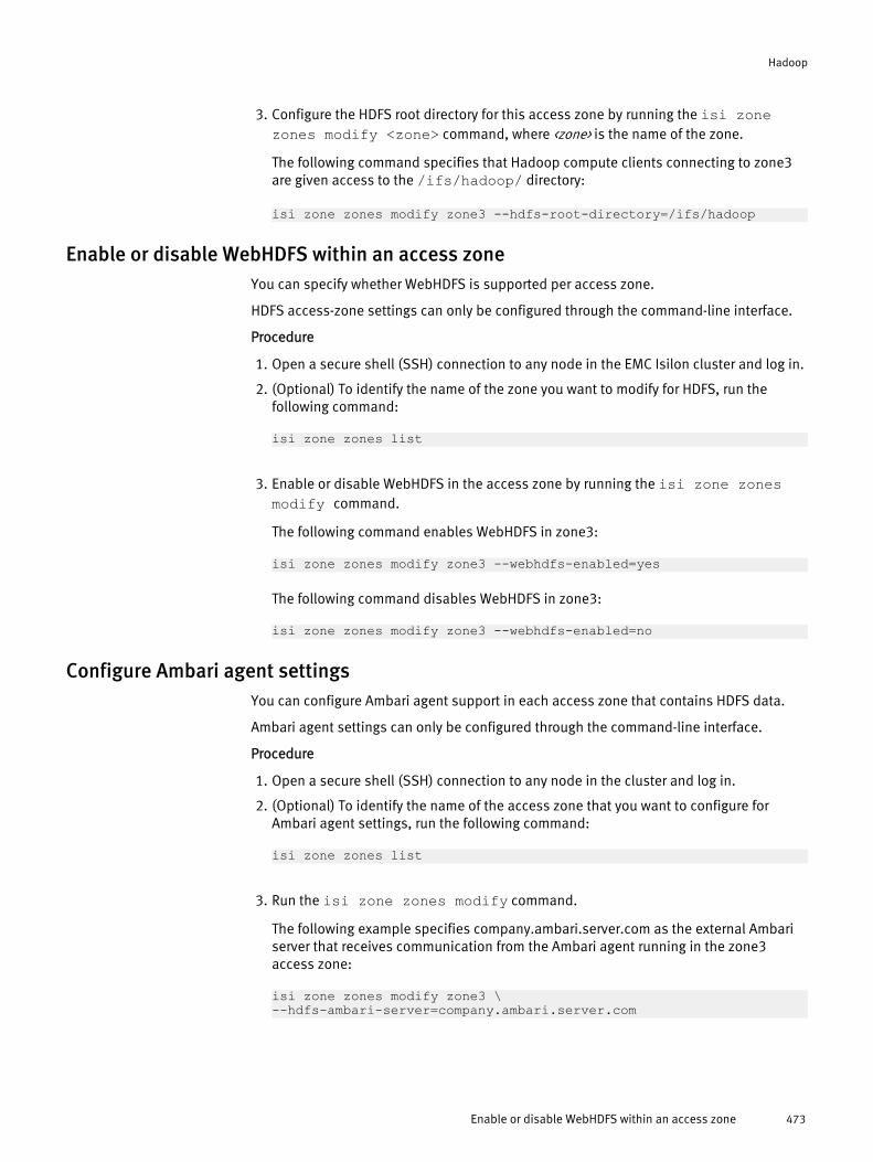
3. Configure the HDFS root directory for this access zone by running the isi zonezones modify <zone> command, where <zone> is the name of the zone.
The following command specifies that Hadoop compute clients connecting to zone3are given access to the /ifs/hadoop/ directory:
isi zone zones modify zone3 --hdfs-root-directory=/ifs/hadoop
Enable or disable WebHDFS within an access zoneYou can specify whether WebHDFS is supported per access zone.
HDFS access-zone settings can only be configured through the command-line interface.
Procedure
1. Open a secure shell (SSH) connection to any node in the EMC Isilon cluster and log in.
2. (Optional) To identify the name of the zone you want to modify for HDFS, run thefollowing command:
isi zone zones list
3. Enable or disable WebHDFS in the access zone by running the isi zone zonesmodify command.
The following command enables WebHDFS in zone3:
isi zone zones modify zone3 --webhdfs-enabled=yes
The following command disables WebHDFS in zone3:
isi zone zones modify zone3 --webhdfs-enabled=no
Configure Ambari agent settingsYou can configure Ambari agent support in each access zone that contains HDFS data.
Ambari agent settings can only be configured through the command-line interface.
Procedure
1. Open a secure shell (SSH) connection to any node in the cluster and log in.
2. (Optional) To identify the name of the access zone that you want to configure forAmbari agent settings, run the following command:
isi zone zones list
3. Run the isi zone zones modify command.
The following example specifies company.ambari.server.com as the external Ambariserver that receives communication from the Ambari agent running in the zone3access zone:
isi zone zones modify zone3 \--hdfs-ambari-server=company.ambari.server.com
Hadoop
Enable or disable WebHDFS within an access zone 473
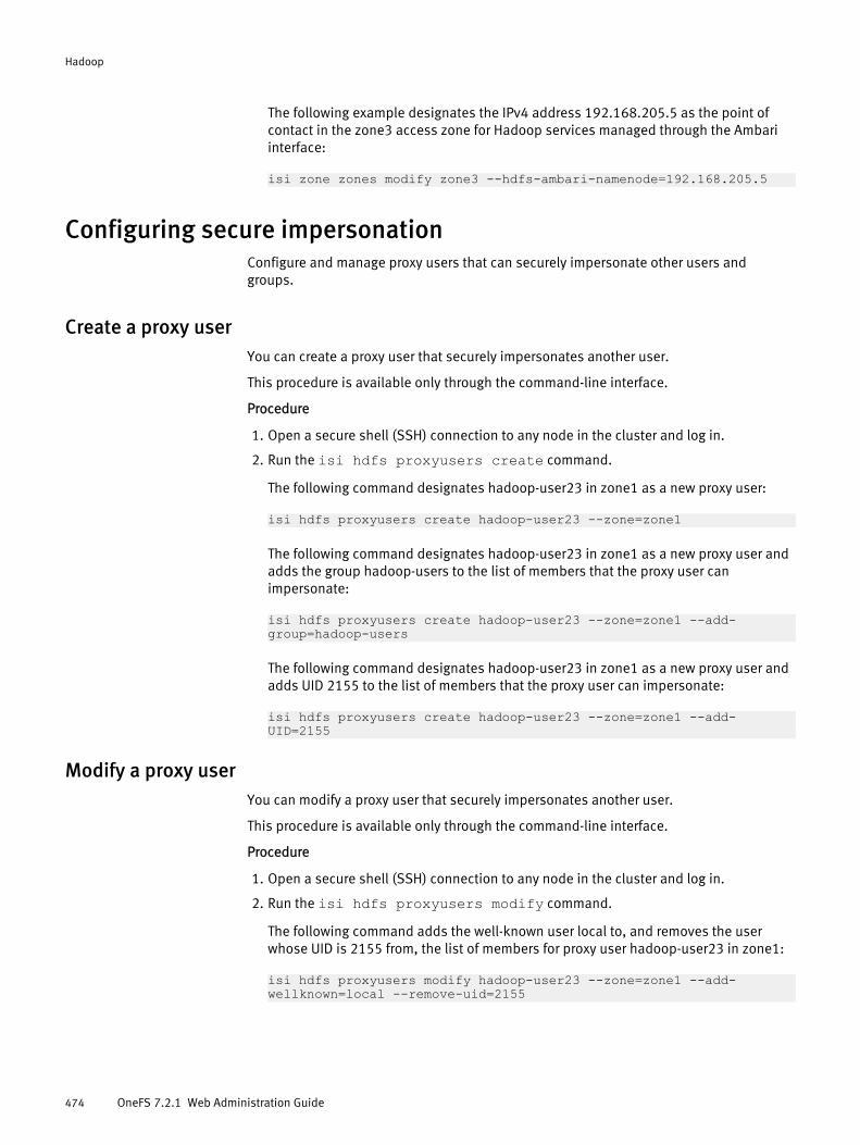
The following example designates the IPv4 address 192.168.205.5 as the point ofcontact in the zone3 access zone for Hadoop services managed through the Ambariinterface:
isi zone zones modify zone3 --hdfs-ambari-namenode=192.168.205.5
Configuring secure impersonationConfigure and manage proxy users that can securely impersonate other users andgroups.
Create a proxy userYou can create a proxy user that securely impersonates another user.
This procedure is available only through the command-line interface.
Procedure
1. Open a secure shell (SSH) connection to any node in the cluster and log in.
2. Run the isi hdfs proxyusers create command.
The following command designates hadoop-user23 in zone1 as a new proxy user:
isi hdfs proxyusers create hadoop-user23 --zone=zone1
The following command designates hadoop-user23 in zone1 as a new proxy user andadds the group hadoop-users to the list of members that the proxy user canimpersonate:
isi hdfs proxyusers create hadoop-user23 --zone=zone1 --add-group=hadoop-users
The following command designates hadoop-user23 in zone1 as a new proxy user andadds UID 2155 to the list of members that the proxy user can impersonate:
isi hdfs proxyusers create hadoop-user23 --zone=zone1 --add-UID=2155
Modify a proxy userYou can modify a proxy user that securely impersonates another user.
This procedure is available only through the command-line interface.
Procedure
1. Open a secure shell (SSH) connection to any node in the cluster and log in.
2. Run the isi hdfs proxyusers modify command.
The following command adds the well-known user local to, and removes the userwhose UID is 2155 from, the list of members for proxy user hadoop-user23 in zone1:
isi hdfs proxyusers modify hadoop-user23 --zone=zone1 --add-wellknown=local --remove-uid=2155
Hadoop
474 OneFS 7.2.1 Web Administration Guide
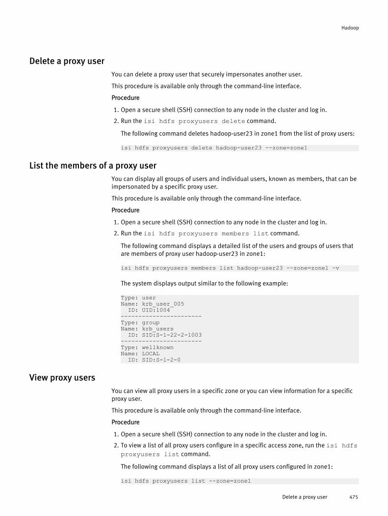
Delete a proxy userYou can delete a proxy user that securely impersonates another user.
This procedure is available only through the command-line interface.
Procedure
1. Open a secure shell (SSH) connection to any node in the cluster and log in.
2. Run the isi hdfs proxyusers delete command.
The following command deletes hadoop-user23 in zone1 from the list of proxy users:
isi hdfs proxyusers delete hadoop-user23 --zone=zone1
List the members of a proxy userYou can display all groups of users and individual users, known as members, that can beimpersonated by a specific proxy user.
This procedure is available only through the command-line interface.
Procedure
1. Open a secure shell (SSH) connection to any node in the cluster and log in.
2. Run the isi hdfs proxyusers members list command.
The following command displays a detailed list of the users and groups of users thatare members of proxy user hadoop-user23 in zone1:
isi hdfs proxyusers members list hadoop-user23 --zone=zone1 -v
The system displays output similar to the following example:
Type: userName: krb_user_005 ID: UID:1004-----------------------Type: groupName: krb_users ID: SID:S-1-22-2-1003-----------------------Type: wellknownName: LOCAL ID: SID:S-1-2-0
View proxy usersYou can view all proxy users in a specific zone or you can view information for a specificproxy user.
This procedure is available only through the command-line interface.
Procedure
1. Open a secure shell (SSH) connection to any node in the cluster and log in.
2. To view a list of all proxy users configure in a specific access zone, run the isi hdfsproxyusers list command.
The following command displays a list of all proxy users configured in zone1:
isi hdfs proxyusers list --zone=zone1
Hadoop
Delete a proxy user 475
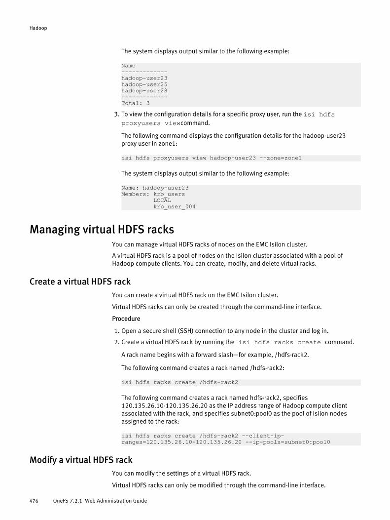
The system displays output similar to the following example:
Name-------------hadoop-user23hadoop-user25hadoop-user28-------------Total: 3
3. To view the configuration details for a specific proxy user, run the isi hdfsproxyusers viewcommand.
The following command displays the configuration details for the hadoop-user23proxy user in zone1:
isi hdfs proxyusers view hadoop-user23 --zone=zone1
The system displays output similar to the following example:
Name: hadoop-user23Members: krb_users LOCAL krb_user_004
Managing virtual HDFS racksYou can manage virtual HDFS racks of nodes on the EMC Isilon cluster.
A virtual HDFS rack is a pool of nodes on the Isilon cluster associated with a pool ofHadoop compute clients. You can create, modify, and delete virtual racks.
Create a virtual HDFS rackYou can create a virtual HDFS rack on the EMC Isilon cluster.
Virtual HDFS racks can only be created through the command-line interface.
Procedure
1. Open a secure shell (SSH) connection to any node in the cluster and log in.
2. Create a virtual HDFS rack by running the isi hdfs racks create command.
A rack name begins with a forward slash—for example, /hdfs-rack2.
The following command creates a rack named /hdfs-rack2:
isi hdfs racks create /hdfs-rack2
The following command creates a rack named hdfs-rack2, specifies120.135.26.10-120.135.26.20 as the IP address range of Hadoop compute clientassociated with the rack, and specifies subnet0:pool0 as the pool of Isilon nodesassigned to the rack:
isi hdfs racks create /hdfs-rack2 --client-ip-ranges=120.135.26.10-120.135.26.20 --ip-pools=subnet0:pool0
Modify a virtual HDFS rackYou can modify the settings of a virtual HDFS rack.
Virtual HDFS racks can only be modified through the command-line interface.
Hadoop
476 OneFS 7.2.1 Web Administration Guide
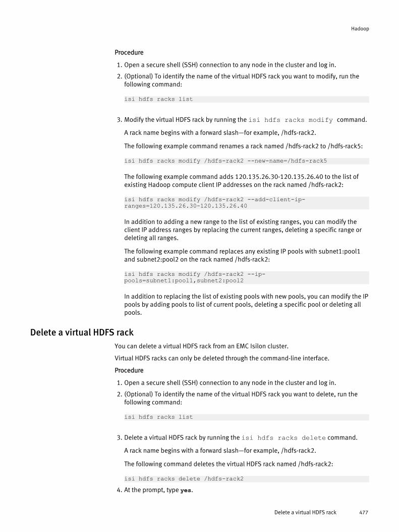
Procedure
1. Open a secure shell (SSH) connection to any node in the cluster and log in.
2. (Optional) To identify the name of the virtual HDFS rack you want to modify, run thefollowing command:
isi hdfs racks list
3. Modify the virtual HDFS rack by running the isi hdfs racks modify command.
A rack name begins with a forward slash—for example, /hdfs-rack2.
The following example command renames a rack named /hdfs-rack2 to /hdfs-rack5:
isi hdfs racks modify /hdfs-rack2 --new-name=/hdfs-rack5
The following example command adds 120.135.26.30-120.135.26.40 to the list ofexisting Hadoop compute client IP addresses on the rack named /hdfs-rack2:
isi hdfs racks modify /hdfs-rack2 --add-client-ip-ranges=120.135.26.30-120.135.26.40
In addition to adding a new range to the list of existing ranges, you can modify theclient IP address ranges by replacing the current ranges, deleting a specific range ordeleting all ranges.
The following example command replaces any existing IP pools with subnet1:pool1and subnet2:pool2 on the rack named /hdfs-rack2:
isi hdfs racks modify /hdfs-rack2 --ip-pools=subnet1:pool1,subnet2:pool2
In addition to replacing the list of existing pools with new pools, you can modify the IPpools by adding pools to list of current pools, deleting a specific pool or deleting allpools.
Delete a virtual HDFS rackYou can delete a virtual HDFS rack from an EMC Isilon cluster.
Virtual HDFS racks can only be deleted through the command-line interface.
Procedure
1. Open a secure shell (SSH) connection to any node in the cluster and log in.
2. (Optional) To identify the name of the virtual HDFS rack you want to delete, run thefollowing command:
isi hdfs racks list
3. Delete a virtual HDFS rack by running the isi hdfs racks delete command.
A rack name begins with a forward slash—for example, /hdfs-rack2.
The following command deletes the virtual HDFS rack named /hdfs-rack2:
isi hdfs racks delete /hdfs-rack24. At the prompt, type yes.
Hadoop
Delete a virtual HDFS rack 477
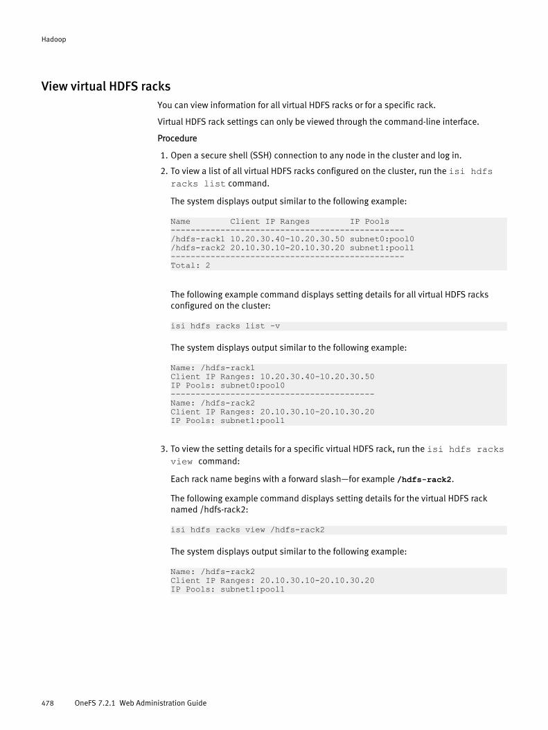
View virtual HDFS racksYou can view information for all virtual HDFS racks or for a specific rack.
Virtual HDFS rack settings can only be viewed through the command-line interface.
Procedure
1. Open a secure shell (SSH) connection to any node in the cluster and log in.
2. To view a list of all virtual HDFS racks configured on the cluster, run the isi hdfsracks list command.
The system displays output similar to the following example:
Name Client IP Ranges IP Pools-----------------------------------------------/hdfs-rack1 10.20.30.40-10.20.30.50 subnet0:pool0/hdfs-rack2 20.10.30.10-20.10.30.20 subnet1:pool1-----------------------------------------------Total: 2
The following example command displays setting details for all virtual HDFS racksconfigured on the cluster:
isi hdfs racks list -v
The system displays output similar to the following example:
Name: /hdfs-rack1Client IP Ranges: 10.20.30.40-10.20.30.50IP Pools: subnet0:pool0-----------------------------------------Name: /hdfs-rack2Client IP Ranges: 20.10.30.10-20.10.30.20IP Pools: subnet1:pool1
3. To view the setting details for a specific virtual HDFS rack, run the isi hdfs racksview command:
Each rack name begins with a forward slash—for example /hdfs-rack2.
The following example command displays setting details for the virtual HDFS racknamed /hdfs-rack2:
isi hdfs racks view /hdfs-rack2
The system displays output similar to the following example:
Name: /hdfs-rack2Client IP Ranges: 20.10.30.10-20.10.30.20IP Pools: subnet1:pool1
Hadoop
478 OneFS 7.2.1 Web Administration Guide
CHAPTER 25
Antivirus
This section contains the following topics:
l Antivirus overview............................................................................................... 480l On-access scanning............................................................................................ 480l Antivirus policy scanning.....................................................................................481l Individual file scanning....................................................................................... 481l Antivirus scan reports......................................................................................... 481l ICAP servers........................................................................................................ 481l Supported ICAP servers....................................................................................... 482l Anitvirus threat responses...................................................................................482l Configuring global antivirus settings................................................................... 483l Managing ICAP servers........................................................................................ 485l Create an antivirus policy.................................................................................... 487l Managing antivirus policies.................................................................................487l Managing antivirus scans....................................................................................488l Managing antivirus threats..................................................................................489l Managing antivirus reports..................................................................................491
Antivirus 479
Antivirus overviewYou can scan the files you store on an Isilon cluster for computer viruses and othersecurity threats by integrating with third-party scanning services through the InternetContent Adaptation Protocol (ICAP). OneFS sends files through ICAP to a server runningthird-party antivirus scanning software. These servers are referred to as ICAP servers.ICAP servers scan files for viruses.
After an ICAP server scans a file, it informs OneFS of whether the file is a threat. If a threatis detected, OneFS informs system administrators by creating an event, displaying nearreal-time summary information, and documenting the threat in an antivirus scan report.You can configure OneFS to request that ICAP servers attempt to repair infected files. Youcan also configure OneFS to protect users against potentially dangerous files bytruncating or quarantining infected files.
Before OneFS sends a file to be scanned, it ensures that the scan is not redundant. If afile has already been scanned and has not been modified, OneFS will not send the file tobe scanned unless the virus database on the ICAP server has been updated since the lastscan.
Note
Antivirus scanning is available only if all nodes in the cluster are connected to theexternal network.
On-access scanningYou can configure OneFS to send files to be scanned before they are opened, after theyare closed, or both. Sending files to be scanned after they are closed is faster but lesssecure. Sending files to be scanned before they are opened is slower but more secure.
If OneFS is configured to ensure that files are scanned after they are closed, when a usercreates or modifies a file on the cluster, OneFS queues the file to be scanned. OneFS thensends the file to an ICAP server to be scanned when convenient. In this configuration,users can always access files without any delay. However, it is possible that after a usermodifies or creates a file, a second user might access the file before the file is scanned. Ifa virus was introduced to the file from the first user, the second user will be able toaccess the infected file. Also, if an ICAP server is unable to scan a file, the file will still beaccessible to users.
If OneFS ensures that files are scanned before they are opened, when a user attempts todownload a file from the cluster, OneFS first sends the file to an ICAP server to bescanned. The file is not sent to the user until the scan is complete. Scanning files beforethey are opened is more secure than scanning files after they are closed, because userscan access only scanned files. However, scanning files before they are opened requiresusers to wait for files to be scanned. You can also configure OneFS to deny access to filesthat cannot be scanned by an ICAP server, which can increase the delay. For example, ifno ICAP servers are available, users will not be able to access any files until the ICAPservers become available again.
If you configure OneFS to ensure that files are scanned before they are opened, it isrecommended that you also configure OneFS to ensure that files are scanned after theyare closed. Scanning files as they are both opened and closed will not necessarilyimprove security, but it will usually improve data availability when compared to scanningfiles only when they are opened. If a user wants to access a file, the file may have already
Antivirus
480 OneFS 7.2.1 Web Administration Guide
been scanned after the file was last modified, and will not need to be scanned again ifthe ICAP server database has not been updated since the last scan.
Antivirus policy scanningYou can create antivirus scanning policies that send files from a specified directory to bescanned. Antivirus policies can be run manually at any time, or configured to runaccording to a schedule.
Antivirus policies target a specific directory on the cluster. You can prevent an antiviruspolicy from sending certain files within the specified root directory based on the size,name, or extension of the file. Antivirus policies do not target snapshots. Only on-accessscans include snapshots. Antivirus scans are handled by the OneFS job engine, andfunction the same as any system job.
Individual file scanningYou can send a specific file to an ICAP server to be scanned at any time.
If a virus is detected in a file but the ICAP server is unable to repair it, you can send thefile to the ICAP server after the virus database had been updated, and the ICAP servermight be able to repair the file. You can also scan individual files to test the connectionbetween the cluster and ICAP servers.
Antivirus scan reportsOneFS generates reports about antivirus scans. Each time that an antivirus policy is run,OneFS generates a report for that policy. OneFS also generates a report every 24 hoursthat includes all on-access scans that occurred during the day.
Antivirus scan reports contain the following information:
l The time that the scan started.
l The time that the scan ended.
l The total number of files scanned.
l The total size of the files scanned.
l The total network traffic sent.
l The network throughput that was consumed by virus scanning.
l Whether the scan succeeded.
l The total number of infected files detected.
l The names of infected files.
l The threats associated with infected files.
l How OneFS responded to detected threats.
ICAP serversThe number of ICAP servers that are required to support an Isilon cluster depends on howvirus scanning is configured, the amount of data a cluster processes, and the processingpower of the ICAP servers.
If you intend to scan files exclusively through antivirus scan policies, it is recommendedthat you have a minimum of two ICAP servers per cluster. If you intend to scan files on
Antivirus
Antivirus policy scanning 481

access, it is recommended that you have at least one ICAP server for each node in thecluster.
If you configure more than one ICAP server for a cluster, it is important to ensure that theprocessing power of each ICAP server is relatively equal. OneFS distributes files to theICAP servers on a rotating basis, regardless of the processing power of the ICAP servers. Ifone server is significantly more powerful than another, OneFS does not send more files tothe more powerful server.
Supported ICAP serversOneFS supports ICAP servers running the following antivirus scanning software:
l Symantec Scan Engine 5.2 and later.
l Trend Micro Interscan Web Security Suite 3.1 and later.
l Kaspersky Anti-Virus for Proxy Server 5.5 and later.
l McAfee VirusScan Enterprise 8.7 and later with VirusScan Enterprise for Storage 1.0and later.
Anitvirus threat responsesYou can configure the system to repair, quarantine, or truncate any files that the ICAPserver detects viruses in.
OneFS and ICAP servers react in one or more of the following ways when threats aredetected:
Alert
All threats that are detected cause an event to be generated in OneFS at the warninglevel, regardless of the threat response configuration.
Repair
The ICAP server attempts to repair the infected file before returning the file to OneFS.
Quarantine
OneFS quarantines the infected file. A quarantined file cannot be accessed by anyuser. However, a quarantined file can be removed from quarantine by the root user ifthe root user is connected to the cluster through secure shell (SSH).
If you backup your cluster through NDMP backup, quarantined files will remainquarantined when the files are restored. If you replicate quarantined files to anotherIsilon cluster, the quarantined files will continue to be quarantined on the targetcluster. Quarantines operate independently of access control lists (ACLs).
Truncate
OneFS truncates the infected file. When a file is truncated, OneFS reduces the size ofthe file to zero bytes to render the file harmless.
You can configure OneFS and ICAP servers to react in one of the following ways whenthreats are detected:
Repair or quarantine
Attempts to repair infected files. If an ICAP server fails to repair a file, OneFSquarantines the file. If the ICAP server repairs the file successfully, OneFS sends the
Antivirus
482 OneFS 7.2.1 Web Administration Guide
file to the user. Repair or quarantine can be useful if you want to protect users fromaccessing infected files while retaining all data on a cluster.
Repair or truncate
Attempts to repair infected files. If an ICAP server fails to repair a file, OneFStruncates the file. If the ICAP server repairs the file successfully, OneFS sends the fileto the user. Repair or truncate can be useful if you do not care about retaining alldata on your cluster, and you want to free storage space. However, data in infectedfiles will be lost.
Alert only
Only generates an event for each infected file. It is recommended that you do notapply this setting.
Repair only
Attempts to repair infected files. Afterwards, OneFS sends the files to the user,whether or not the ICAP server repaired the files successfully. It is recommended thatyou do not apply this setting. If you only attempt to repair files, users will still beable to access infected files that cannot be repaired.
Quarantine
Quarantines all infected files. It is recommended that you do not apply this setting. Ifyou quarantine files without attempting to repair them, you might deny access toinfected files that could have been repaired.
Truncate
Truncates all infected files. It is recommended that you do not apply this setting. Ifyou truncate files without attempting to repair them, you might delete dataunnecessarily.
Configuring global antivirus settingsYou can configure global antivirus settings that are applied to all antivirus scans bydefault.
Exclude files from antivirus scansYou can prevent files from being scanned by antivirus policies.
Procedure
1. Click Data Protection > Antivirus > Settings.
2. In the File size restriction area, specify whether to exclude files from being scannedbased on size.
l Click Scan all files regardless of size.
l Click Only scan files smaller than the maximum file size and specify a maximumfile size.
3. In the Filename restrictions area, specify whether to exclude files from being scannedbased on file names and extensions.
l Click Scan all files.
l Click Only scan files with the following extensions or filenames.
Antivirus
Configuring global antivirus settings 483
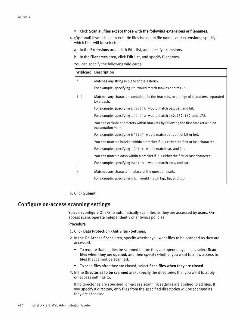
l Click Scan all files except those with the following extensions or filenames.
4. (Optional) If you chose to exclude files based on file names and extensions, specifywhich files will be selected.
a. In the Extensions area, click Edit list, and specify extensions.
b. In the Filenames area, click Edit list, and specify filenames.
You can specify the following wild cards:
Wildcard Description
* Matches any string in place of the asterisk.
For example, specifying m* would match movies and m123.
[ ] Matches any characters contained in the brackets, or a range of characters separatedby a dash.
For example, specifying b[aei]t would match bat, bet, and bit.
For example, specifying 1[4-7]2 would match 142, 152, 162, and 172.
You can exclude characters within brackets by following the first bracket with anexclamation mark.
For example, specifying b[!ie] would match bat but not bit or bet.
You can match a bracket within a bracket if it is either the first or last character.
For example, specifying [[c]at would match cat, and [at.
You can match a dash within a bracket if it is either the first or last character.
For example, specifying car[-s] would match cars, and car-.
? Matches any character in place of the question mark.
For example, specifying t?p would match tap, tip, and top.
5. Click Submit.
Configure on-access scanning settingsYou can configure OneFS to automatically scan files as they are accessed by users. On-access scans operate independently of antivirus policies.
Procedure
1. Click Data Protection > Antivirus > Settings.
2. In the On Access Scans area, specify whether you want files to be scanned as they areaccessed.
l To require that all files be scanned before they are opened by a user, select Scanfiles when they are opened, and then specify whether you want to allow access tofiles that cannot be scanned.
l To scan files after they are closed, select Scan files when they are closed.
3. In the Directories to be scanned area, specify the directories that you want to applyon-access settings to.
If no directories are specified, on-access scanning settings are applied to all files. Ifyou specify a directory, only files from the specified directories will be scanned asthey are accessed.
Antivirus
484 OneFS 7.2.1 Web Administration Guide
4. Click Submit.
Configure antivirus threat response settingsYou can configure how OneFS responds to detected threats.
Procedure
1. Click Data Protection > Antivirus > Settings.
2. In the Action on detection area, specify how you want OneFS to react to potentiallyinfected files.
Configure antivirus report retention settingsYou can configure how long OneFS retains antivirus reports before automatically deletingthem.
Procedure
1. Click Data Protection > Antivirus > Settings.
2. In the Reports area, specify how long you want OneFS to keep reports for.
Enable or disable antivirus scanningYou can enable or disable all antivirus scanning. This procedure is available only throughthe web administration interface.
Procedure
1. Click Data Protection > Antivirus > Summary.
2. In the Service area, click Enable or Disable.
Managing ICAP serversBefore you can send files to be scanned on an ICAP server, you must configure OneFS toconnect to the server. You can test, modify, and remove an ICAP server connection. Youcan also temporarily disconnect and reconnect to an ICAP server.
Add and connect to an ICAP serverYou can add and connect to an ICAP server. After a server is added, OneFS can send filesto the server to be scanned for viruses.
Procedure
1. Click Data Protection > Antivirus > Summary.
2. In the ICAP Servers area, click Add server.
3. In the Add ICAP Server dialog box, in the ICAP URL field, type the IPv4 or IPv6 addressof an ICAP server.
4. (Optional) In the Description field, type a description of this ICAP server.
5. Click Submit.
The ICAP server is displayed in the ICAP Servers table.
Antivirus
Configure antivirus threat response settings 485
Test an ICAP server connectionYou can test the connection between the cluster and an ICAP server. This procedure isavailable only through the web administration interface.
Procedure
1. Click Data Protection > Antivirus > Summary.
2. In the ICAP Servers table, in the row for the ICAP server, click Test connection.
If the connection test succeeds, the Status column displays a green icon. If theconnection test fails, the Status column displays a red icon.
Modify ICAP connection settingsYou can modify the IP address and optional description of ICAP server connections.
Procedure
1. Click Data Protection > Antivirus > Summary.
2. In the ICAP Servers table, in the row for an ICAP server, click Edit.
3. Modify settings, and then click Submit.
Temporarily disconnect from an ICAP serverIf you want to prevent OneFS from sending files to an ICAP server, but want to retain theICAP server connection settings, you can temporarily disconnect from the ICAP server.
Procedure
1. Click Data Protection > Antivirus > Summary.
2. In the ICAP Servers table, in the row for an ICAP server, click Disable.
Reconnect to an ICAP serverYou can reconnect to an ICAP server that you have temporarily disconnected from.
Procedure
1. Click Data Protection > Antivirus > Summary.
2. In the ICAP Servers table, in the row for an ICAP server, click Enable.
Remove an ICAP serverYou can permanently disconnect from the ICAP server.
Procedure
1. Click Data Protection > Antivirus > Summary.
2. In the ICAP Servers table, in the row for an ICAP server, click Delete.
Antivirus
486 OneFS 7.2.1 Web Administration Guide
Create an antivirus policyYou can create an antivirus policy that causes specific files to be scanned for viruseseach time the policy is run.
Procedure
1. Click Data Protection > Antivirus > Policies.
2. Click Add policy.
3. In the Name field, type a name for the antivirus policy.
4. Click Add directory and select a directory that you want to scan.
Optionally, repeat this step to specify multiple directories.
5. In the Restrictions area, specify whether you want to enforce the file size and namerestrictions specified by the global antivirus settings.
l Click Enforce file size and filename restrictions.
l Click Scan all files within the root directories.
6. In the Run policy area, specify whether you want to run the policy according to aschedule or manually.
Scheduled policies can also be run manually at any time.
Option Description
Run the policy onlymanually.
Click Manually
Run the policy accordingto a schedule.
a. Click Scheduled.
b. In the Interval area, specify on what days you wantthe policy to run.
c. In the Frequency area, specify how often you want thepolicy to run on the specified days.
7. Click Submit.
Managing antivirus policiesYou can modify and delete antivirus policies. You can also temporarily disable antiviruspolicies if you want to retain the policy but do not want to scan files.
Modify an antivirus policyYou can modify an antivirus policy.
Procedure
1. Click Data Protection > Antivirus > Policy.
2. In the Policies table, click the name of the antivirus policy that you want to modify.
3. Modify settings, and then click Submit.
Antivirus
Create an antivirus policy 487
Delete an antivirus policyYou can delete an antivirus policy.
Procedure
1. Click Data Protection > Antivirus > Policies.
2. In the Policies table, in the row for an antivirus policy, click Delete.
Enable or disable an antivirus policyYou can temporarily disable antivirus policies if you want to retain the policy but do notwant to scan files.
Procedure
1. Click Data Protection > Antivirus > Policies.
2. In the Policies table, in the row for an antivirus policy, click Enable or Disable.
View antivirus policiesYou can view antivirus policies.
Procedure
1. Click Data Protection > Antivirus > Policies.
2. In the Policies table, view antivirus policies.
Managing antivirus scansYou can scan multiple files for viruses by manually running an antivirus policy, or scan anindividual file without an antivirus policy. You can also stop antivirus scans.
Scan a fileYou can manually scan an individual file for viruses. This procedure is available onlythrough the command-line interface (CLI).
Procedure
1. Open a secure shell (SSH) connection to any node in the cluster and log in.
2. Run the isi avscan manual command.
For example, the following command scans /ifs/data/virus_file:
isi avscan manual /ifs/data/virus_file
Manually run an antivirus policyYou can manually run an antivirus policy at any time. This procedure is available onlythrough the web administration interface.
Procedure
1. Click Data Protection > Antivirus > Policies.
2. In the Policies table, in the row for a policy, click Start.
Antivirus
488 OneFS 7.2.1 Web Administration Guide
Stop a running antivirus scanYou can stop a running antivirus scan. This procedure is available only through the webadministration interface.
Procedure
1. Click Data Protection > Antivirus > Summary.
2. In the Currently Running table, in the row for an antivirus scan, click Cancel.
Managing antivirus threatsYou can repair, quarantine, or truncate files in which threats are detected. If you thinkthat a quarantined file is no longer a threat, you can rescan the file or remove the file fromquarantine.
Manually quarantine a fileYou can quarantine a file to prevent the file from being accessed by users.
Procedure
1. Click Data Protection > Antivirus > Detected Threats.
2. In the Detected Threats table, in the row of a file, click Quarantine.
Rescan a fileYou can rescan the file for viruses if, for example, you believe that a file is no longer athreat.
Procedure
1. Click Data Protection > Antivirus > Detected Threats.
2. In the Detected Threats table, in the row of a file, click Rescan.
Remove a file from quarantineYou can remove a file from quarantine if, for example, you believe that the file is nolonger a threat.
Procedure
1. Click Data Protection > Antivirus > Detected Threats.
2. In the Detected Threats table, in the row of a file, click Restore.
Manually truncate a fileIf a threat is detected in a file, and the file is irreparable and no longer needed, you cantruncate the file.
Procedure
1. Click Data Protection > Antivirus > Detected Threats.
2. In the Detected Threats table, in the row for a file, click Truncate.
The Confirm dialog box appears.
3. Click Yes.
Antivirus
Stop a running antivirus scan 489
View threatsYou can view files that have been identified as threats by an ICAP server.
Procedure
1. Click Data Protection > Antivirus > Detected Threats.
2. In the Detected Threats table, view potentially infected files.
Antivirus threat informationYou can view information about the antivirus threats that are reported by an ICAP server.
Status
The color of the icon indicates the status of the potentially infected file.
Red
OneFS did not take any action on the file.
Orange
OneFS truncated the file.
Yellow
OneFS quarantined the file.
Threat
Displays the name of the detected threat as it is recognized by the ICAP server.
Filename
Displays the name of the potentially infected file.
Directory
Displays the directory in which the file is located.
Remediation
Indicates how OneFS responded to the file when the threat was detected. If OneFSdid not quarantine or truncate the file, Infected appears.
Detected
Displays the time that the threat was detected.
Policy
Displays the name of the antivirus policy that caused the threat to be detected. If thethreat was detected as a result of a manual antivirus scan of an individual file,Manual scan appears.
Currently
Displays the current state of the file.
File size
Displays the size of the file in bytes. Truncated files display a size of zero bytes.
Antivirus
490 OneFS 7.2.1 Web Administration Guide
Managing antivirus reportsIn addition to viewing antivirus reports through the web administration interface, you canexport reports to a comma-separated values (CSV) file. You can also view events that arerelated to antivirus activity.
Export an antivirus reportYou can export an antivirus report to a comma separated values (CSV) file.
Procedure
1. Click Data Protection > Antivirus > Reports.
2. In the Reports table, in the row for a report, click Export.
3. Save the CSV file.
View antivirus reportsYou can view antivirus reports.
Procedure
1. Click Data Protection > Antivirus > Reports.
2. In the Reports table, in the row for a report, click View Details.
View antivirus eventsYou can view events that relate to antivirus activity.
Procedure
1. Click Dashboard > Events > Event History.
2. In the Event History table, view all events.
All events related to antivirus scans are classified as warnings. The following eventsare related to antivirus activities:
Anti-Virus scan found threatsA threat was detected by an antivirus scan. These events refer to specific reportson the Antivirus Reports page but do not provide threat details.
No ICAP Servers availableOneFS is unable to communicate with any ICAP servers.
ICAP Server Unresponsive or InvalidOneFS is unable to communicate with an ICAP server.
Antivirus
Managing antivirus reports 491

Antivirus
492 OneFS 7.2.1 Web Administration Guide

CHAPTER 26
VMware integration
This section contains the following topics:
l VMware integration overview...............................................................................494l VAAI.................................................................................................................... 494l VASA...................................................................................................................494l Configuring VASA support................................................................................... 495l Disable or re-enable VASA...................................................................................498l Troubleshooting VASA storage display failures....................................................499
VMware integration 493
VMware integration overviewOneFS integrates with VMware infrastructures, including vSphere, vCenter, and ESXi.VMware integration enables you to view information about and interact with Isilonclusters through VMware applications.
OneFS interacts with VMware infrastructures through VMware vSphere API for StorageAwareness (VASA) and VMware vSphere API for Array Integration (VAAI).
OneFS integrates with VMware vCenter through the Isilon for vCenter plug-in. The Isilonfor vCenter plug-in enables you to locally backup and restore virtual machines on anIsilon cluster. For more information about Isilon for vCenter, see the following documents:
l Isilon for vCenter Release Notes
l Isilon for vCenter Installation Guide
l Isilon for vCenter User Guide
VAAIOneFS uses VMware vSphere API for Array Integration (VAAI) to support offloadingspecific virtual machine storage and management operations from VMware ESXihypervisors to an Isilon cluster.
VAAI support enables you to accelerate the process of creating virtual machines andvirtual disks. For OneFS to interact with your vSphere environment through VAAI, yourVMware environment must include ESXi 5.0 or later hypervisors.
If you enable VAAI capabilities for an Isilon cluster, when you clone a virtual machineresiding on the cluster through VMware, OneFS clones the files related to that virtualmachine.
To enable OneFS to use VMware vSphere API for Array Integration (VAAI), you must installthe VAAI NAS plug-in for Isilon on the ESXi server. For more information on the VAAI NASplug-in for Isilon, see the VAAI NAS plug-in for Isilon Release Notes.
VASAOneFS communicates with VMware vSphere through VMware vSphere API for StorageAwareness (VASA).
VASA support enables you to view information about Isilon clusters through vSphere,including Isilon-specific alarms in vCenter. VASA support also enables you to integratewith VMware profile driven storage by providing storage capabilities for Isilon clusters invCenter. For OneFS to communicate with vSphere through VASA, your VMwareenvironment must include ESXi 5.0 or later hypervisors.
Isilon VASA alarmsIf the VASA service is enabled on an Isilon cluster and the cluster is added as a VMwarevSphere API for Storage Awareness (VASA) vendor provider in vCenter, OneFS generatesalarms in vSphere.
The following table describes the alarm that OneFS generates:
VMware integration
494 OneFS 7.2.1 Web Administration Guide
Alarm name Description
Thin-provisioned LUNcapacity exceeded
There is not enough available space on the cluster to allocate space forwriting data to thinly provisioned LUNs. If this condition persists, you willnot be able to write to the virtual machine on this cluster. To resolve thisissue, you must free storage space on the cluster.
VASA storage capabilitiesOneFS integrates with VMware vCenter through VMware vSphere API for StorageAwareness (VASA) to display storage capabilities of Isilon clusters in vCenter.
The following storage capabilities are displayed through vCenter:
Archive
The Isilon cluster is composed of Isilon NL-Series nodes. The cluster is configured formaximum capacity.
Performance
The Isilon cluster is composed of Isilon i-Series, Isilon X-Series, or Isilon S-Seriesnodes. The cluster is configured for maximum performance.
Note
If a node type supports SSDs but none are installed, the cluster is recognized as acapacity cluster.
Capacity
The Isilon cluster is composed of Isilon X-Series nodes that do not contain SSDs. Thecluster is configured for a balance between performance and capacity.
Hybrid
The Isilon cluster is composed of nodes associated with two or more storagecapabilities. For example, if the cluster contained both Isilon S-Series and NL-Seriesnodes, the storage capability of the cluster is displayed as Hybrid.
Configuring VASA supportTo enable VMware vSphere API for Storage Awareness (VASA) support for a cluster, youmust enable the VASA daemon on the cluster and add the Isilon vendor providercertificate in vCenter.
Note
If you are running vCenter version 6.0, you must create a self-signed certificate asdescribed in the Create a self-signed certificate section before adding the Isilon vendorprovider certificate and registering the VASA provider through vCenter.
VMware integration
VASA storage capabilities 495

Enable VASAYou must enable an Isilon cluster to communicate with VMware vSphere API for StorageAwareness (VASA) by enabling the VASA daemon.
Procedure
1. Open a secure shell (SSH) connection to any node in the cluster and log in.
2. Enable VASA by running the following command:
isi services isi_vasa_d enable
Download the Isilon vendor provider certificateTo add an Isilon cluster VASA vendor provider in VMware vCenter, you must use a vendorprovider certificate.
Procedure
1. In a supported web browser, connect to an Isilon cluster at https://<IPAddress>, where <IPAddress> is the IP address of the Isilon cluster.
2. Add a security exception and view the security certificate to make sure that it iscurrent.
3. Download the security certificate and save it to a location on your machine.
For more information about exporting a security certificate, see the documentation ofyour browser.
Note
Record the location of where you saved the certificate. You will need this file pathwhen adding the vendor provider in vCenter.
After you finish
If you are running vCenter version 6.0, follow the instructions in the Create a self-signedcertificate section. If you are running the previous versions of vCenter, skip the nextsection and follow the instructions in the Add the Isilon vendor provider section.
Create a self-signed certificateIf you are running VMware vCenter version 6.0, you must create a new self-signedcertificate before adding and registering a VASA provider through vCenter.
You can create a self-signed certificate by opening a secure shell (SSH) connection to anode in the EMC Isilon cluster that will be used as the VASA provider. Alternatively, aftercreating a self-signed certificate on a node, you can copy the certificate to any other nodein the cluster and register that node as a VASA provider in vCenter.
Procedure
1. Create an RSA key by running the following command:
openssl genrsa -aes128 -out vp.key 1024
VMware integration
496 OneFS 7.2.1 Web Administration Guide
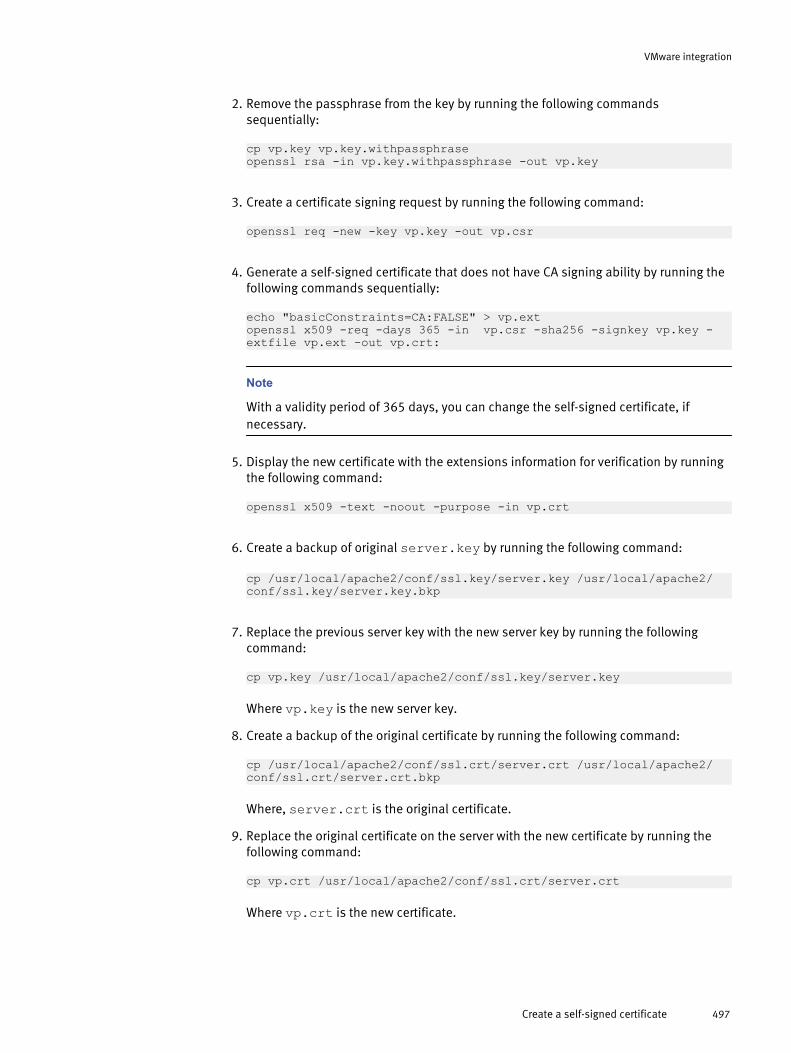
2. Remove the passphrase from the key by running the following commandssequentially:
cp vp.key vp.key.withpassphraseopenssl rsa -in vp.key.withpassphrase -out vp.key
3. Create a certificate signing request by running the following command:
openssl req -new -key vp.key -out vp.csr
4. Generate a self-signed certificate that does not have CA signing ability by running thefollowing commands sequentially:
echo "basicConstraints=CA:FALSE" > vp.extopenssl x509 -req -days 365 -in vp.csr -sha256 -signkey vp.key -extfile vp.ext -out vp.crt:
Note
With a validity period of 365 days, you can change the self-signed certificate, ifnecessary.
5. Display the new certificate with the extensions information for verification by runningthe following command:
openssl x509 -text -noout -purpose -in vp.crt
6. Create a backup of original server.key by running the following command:
cp /usr/local/apache2/conf/ssl.key/server.key /usr/local/apache2/conf/ssl.key/server.key.bkp
7. Replace the previous server key with the new server key by running the followingcommand:
cp vp.key /usr/local/apache2/conf/ssl.key/server.key
Where vp.key is the new server key.
8. Create a backup of the original certificate by running the following command:
cp /usr/local/apache2/conf/ssl.crt/server.crt /usr/local/apache2/conf/ssl.crt/server.crt.bkp
Where, server.crt is the original certificate.
9. Replace the original certificate on the server with the new certificate by running thefollowing command:
cp vp.crt /usr/local/apache2/conf/ssl.crt/server.crt
Where vp.crt is the new certificate.
VMware integration
Create a self-signed certificate 497
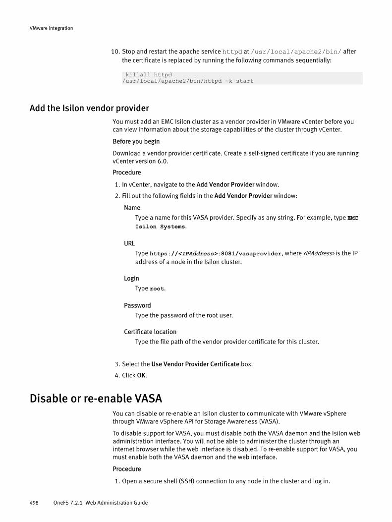
10. Stop and restart the apache service httpd at /usr/local/apache2/bin/ afterthe certificate is replaced by running the following commands sequentially:
killall httpd/usr/local/apache2/bin/httpd -k start
Add the Isilon vendor providerYou must add an EMC Isilon cluster as a vendor provider in VMware vCenter before youcan view information about the storage capabilities of the cluster through vCenter.
Before you begin
Download a vendor provider certificate. Create a self-signed certificate if you are runningvCenter version 6.0.
Procedure
1. In vCenter, navigate to the Add Vendor Provider window.
2. Fill out the following fields in the Add Vendor Provider window:
Name
Type a name for this VASA provider. Specify as any string. For example, type EMCIsilon Systems.
URL
Type https://<IPAddress>:8081/vasaprovider, where <IPAddress> is the IPaddress of a node in the Isilon cluster.
Login
Type root.
Password
Type the password of the root user.
Certificate location
Type the file path of the vendor provider certificate for this cluster.
3. Select the Use Vendor Provider Certificate box.
4. Click OK.
Disable or re-enable VASAYou can disable or re-enable an Isilon cluster to communicate with VMware vSpherethrough VMware vSphere API for Storage Awareness (VASA).
To disable support for VASA, you must disable both the VASA daemon and the Isilon webadministration interface. You will not be able to administer the cluster through aninternet browser while the web interface is disabled. To re-enable support for VASA, youmust enable both the VASA daemon and the web interface.
Procedure
1. Open a secure shell (SSH) connection to any node in the cluster and log in.
VMware integration
498 OneFS 7.2.1 Web Administration Guide
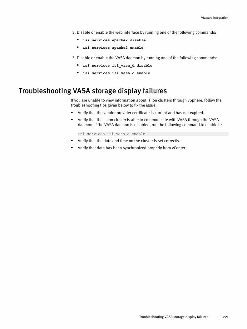
2. Disable or enable the web interface by running one of the following commands:
l isi services apache2 disablel isi services apache2 enable
3. Disable or enable the VASA daemon by running one of the following commands:
l isi services isi_vasa_d disablel isi services isi_vasa_d enable
Troubleshooting VASA storage display failuresIf you are unable to view information about Isilon clusters through vSphere, follow thetroubleshooting tips given below to fix the issue.
l Verify that the vendor provider certificate is current and has not expired.
l Verify that the Isilon cluster is able to communicate with VASA through the VASAdaemon. If the VASA daemon is disabled, run the following command to enable it:
isi services isi_vasa_d enablel Verify that the date and time on the cluster is set correctly.
l Verify that data has been synchronized properly from vCenter.
VMware integration
Troubleshooting VASA storage display failures 499

VMware integration
500 OneFS 7.2.1 Web Administration Guide
CHAPTER 27
File System Explorer
This section contains the following topics:
l File System Explorer overview..............................................................................502l Browse the file system........................................................................................ 502l Create a directory................................................................................................ 503l Modify file and directory properties..................................................................... 503l View file and directory properties........................................................................ 504l File and directory properties................................................................................504
File System Explorer 501
File System Explorer overviewThe File System Explorer is a web-based interface that enables you to manage the contentstored on your EMC Isilon cluster. You can use the File System Explorer to navigate theIsilon file system (/ifs), add directories, and manage file and directory propertiesincluding data protection, I/O optimization, and UNIX permissions.
Isilon file system directory permissions are initially set to allow full access for all users.Any user can delete any file, regardless of the permissions on the individual file.Depending on your environment, you should establish appropriate permissionrestrictions through the File System Explorer.
File System Explorer supports access zones. By default, the root user and sysadmin haveaccess to the top-level access zone, System (/ifs). Other users can be restricted tospecific access zones—for example, /ifs/home.
You can view and configure file and directory properties from within Windows clients thatare connected to the cluster. However, because Windows and UNIX permissions differfrom one another, you must be careful not to make any unwanted changes that affect fileand directory access.
Browse the file systemYou can browse the Isilon file system (/ifs) through the File System Explorer.
Procedure
1. Navigate to File System Management > File System Explorer.
2. View files and directories.
l You can expand and collapse directories in the Directories pane.
l The contents of the selected directory are displayed in the right pane. You can viewthe contents of another directory by clicking the directory in the Directories pane.
File System Explorer
502 OneFS 7.2.1 Web Administration Guide

File System Explorer iconsThe following icons appear in the File System Explorer:
Folder
Represents a directory.
Folder with a red lock
Represents a directory that contains a SmartLock directory.
Red lock
Represents a SmartLock directory.
Yellow lock
Represents a directory that is contained within a SmartLock directory.
Sheet of paper
Represents a file
Sheet of paper with a red lock
Represents a file that has been committed to a WORM state.
Create a directoryYou can create a directory under /ifs through the File System Explorer.
Procedure
1. Navigate to File System Management > File System Explorer.
2. In the Directories pane, specify where you want to create the directory.
3. Click Add Directory.
4. In the New Directory Properties dialog box, in the Directory name field, type a namefor the directory.
5. From the User list, select the owner of the directory.
6. From the Group list, select the group for the directory.
7. From the Permissions table, specify the basic permissions for the directory.
8. Click Submit.
Modify file and directory propertiesYou can modify the data protection, I/O optimization, and UNIX permission properties offiles and directories through the File System Explorer.
Procedure
1. Navigate to File System Management > File System Explorer.
2. In the Directories pane, click the directory that contains the file or directory that youwant to modify permissions for.
3. In the right pane, in the row of the file or directory you want to modify permissions for,click Properties.
File System Explorer
File System Explorer icons 503
4. In the Properties dialog box, specify the properties of the file or directory.
5. Click Submit.
View file and directory propertiesYou can view the data protection, I/O optimization, and UNIX permission properties offiles and directories through the File System Explorer.
Procedure
1. Navigate to File System Management > File System Explorer.
2. In the Directories pane, click the directory that contains the file or directory that youwant to view permissions for.
3. In the right pane, in the row of the file or directory you want to view permissions for,click Properties.
4. In the Properties dialog box, view the properties of the file or directory.
File and directory propertiesEach file and directory is assigned specific data protection, I/O optimization, and UNIXpermission properties that you can view through the File System Explorer.
The following properties are displayed in the Properties dialog box of the File SystemExplorer:
Protection Settings
Settings management
Specifies whether protection settings are managed manually or by SmartPools. If youmodify either or both protection settings, this property automatically refreshes toManually managed. If you specify Managed by SmartPools, the protectionsettings will automatically refresh to match the SmartPools specifications the nexttime the SmartPools job is run.
Disk pool
The disk pool whose requested protection is applied if SmartPools is configured tomanage protection settings. This property is available only if SmartPools is licensedand enabled on the cluster.
SSD
The SSD strategy that will be used for user data and metadata if solid-state drives(SSDs) are available. The following SSD strategies are available:
Metadata acceleration
OneFS creates a mirror backup of file metadata on an SSD and writes the rest ofthe metadata plus all user data to hard disk drives (HDDs). Depending on theglobal namespace acceleration setting, the SSD mirror might be an extra mirrorin addition to the number required to satisfy the protection level.
Avoid SSDs
OneFS does not write data or metadata to SSDs. OneFS writes all data andmetadata to HDDs only.
File System Explorer
504 OneFS 7.2.1 Web Administration Guide
Data on SSDs
Similar to metadata acceleration, OneFS creates a mirror backup of filemetadata on an SSD and writes the rest of the metadata plus all user data tohard disk drives. However, OneFS also writes one copy of the file user data (ifmirrored) or all of the data (if not mirrored) to SSDs. All SSD blocks reside on thefile target pool if there is adequate space available, regardless of whetherglobal namespace acceleration is enabled. OneFS does not create additionalmirrors beyond the normal protection level.
Actual protection
The FlexProtect or data-mirroring requested protection for this file or directory. IfSmartPools is licensed and enabled on the cluster, the default requested protectionfor files and directories is inherited from the specified disk pool.
I/O Optimization Settings
Settings Management
Specifies whether I/O Optimization Settings are managed manually or bySmartPools. If you modify either or both I/O optimization settings, this propertyautomatically refreshes to Manually managed. If you specify Managed bySmartPools, the I/O optimization settings values will automatically refresh to matchthe SmartPools specifications the next time the SmartPools job is run.
SmartCache
Specifies whether write caching with SmartCache is enabled for this file or directory.
Data access pattern
The optimization settings for accessing data. The following data access patterns areavailable:
Concurrency
File or directory is optimized to support many clients simultaneously.
Streaming
File or directory is optimized for high-speed streaming of a single file. Forexample, this pattern can be useful if a single client needs to read very quicklyfrom a single file.
Random
File or directory is optimized for unpredictable access.
The default data access pattern of iSCSI LUNs is the random access pattern. Thedefault data access pattern of other files and directories is the concurrent accesspattern.
UNIX Permissions
User
The owner of the file or directory.
Group
The group of the file or directory.
File System Explorer
File and directory properties 505

Permissions
The basic permissions for the file or directory.
File System Explorer
506 OneFS 7.2.1 Web Administration Guide