online appendix e getting started with mysql workbench ... · database processing appendix e e-6...
TRANSCRIPT

Database Processing: Fundamentals, Design, and Implementation
12th Edition
David M. Kroenke • David J. Auer
Online Appendix E
Getting Started with MySQL Workbench Data Modeling Tools

Database Processing Appendix E
E-2
Appendix E — 10 9 8 7 6 5 4 3 2 1

Database Processing Appendix E
E-3
Objectives:
To learn how to install the MySQL ODBC/Connector
To learn how to create database designs in the MySQL Workbench
What is the Purpose of this Appendix?
One widely used edition of MySQL 5.5 is the MySQL Community Server, which is an open-source, freely
downloadable, enterprise-class DBMS that has been around for many years. In November 2005, MySQL
5.0 was released, and, as of this writing, MySQL 5.5 is the generally available (GA) release, with MySQL
5.6 in development. In February 2008, Sun Microsystems completed its acquisition of MySQL AB, the
company that created and owned MySQL, only to have Oracle Corporation acquire Sun Microsystems
(the deal was finalized on January 27th, 2010, after European Commission approval on January 21st,
2010—see http://www.sun.com/third-party/global/oracle/ ) The Oracle corporation now owns MySQL
in addition to its flagship Oracle Database product.1 MySQL, while not having as many features as SQL
Server, has become widely used and very popular as a DBMS supporting Web sites running the Apache
Web server. The MySQL Workbench graphical user interface (GUI) utility is the main user interface
when using MySQL. The MySQL Connector/ODBC is the ODBC driver for the MySQL DBMS. Open Data-
base Connectivity (ODBC) and OBDC Drivers are discussed in Chapter 11. You will need the MySQL Con-
nector/ODBC if you are using the MySQL DBMS and you want to create the Web database applications
and Web pages discussed in Chapter 11.
1 For information about Oracle Database 11g, see online Chapter 10A.

Database Processing Appendix E
E-4
The purpose of this Appendix is to:
Learn how to use the MySQL Workbench to create database designs as discussed in Chapter 6.
Learn how to install the MySQL Connector/ODBC for use with Web database applications as
discussed in Chapter 11.
Installation and administration of MySQL 5.5, including developing and using databases, is discussed in
Chapter 10B. MySQL and its associated utilities are very easy to install. At this point, install and configure
MySQL Community Edition 5.5 and the MySQL workbench. We will discuss the MySQL Connector/ODBC
later in this appendix.
Why Should I Learn to Use the MySQL Workbench for Database Design?
The MySQL Workbench contains a good set of features for creating database designs. If you are working
with the MySQL DBMS, this is a natural pairing, and you will be using the same GUI for database
designing and implementation. Even if you aren’t using the MySQL DBMS, the database design
capablities of the MySQL Workbench make it well worth considering as your database design tool.
What Will This Appendix Teach Me?
This appendix is designed to get you started creating database designs using the MySQL Workbench, and
discuss the installation of the MySQL Connector/ODBC.
What Won’t This Appendix Teach Me?
The MySQL Workbench has many capabilities beyond those described in Chapter 10B and this Appendix.
It is possible, for example, to use the MySQL Workbench to reverse engineer (discussed in Chapter 8)
MySQL databases. It is also possible to create a database in MySQL from a database design in MySQL
Workbench. For more information on the capabilities of the MySQL Workbench, see the MySQL
Workbench documentation available at http://dev.mysql.com/doc/workbench/en/.
How Do I Install the MySQL Workbench and the MySQL Connector/ODBC?
Unlike the installation of Microsoft Access 2010 (separately or as part of Office 2010), or Microsoft SQL
Server 2008 R2, or Oracle Database 11g, where the GUI management utility and ODBC support is installed as
part of the DBMS installation, you may have to take extra steps to install the MySQL Workbench and ODBC
support for MySQL. Fortunately, MySQL and its associated utilities are very easy to install. A full
disucssion of the installation and administration of the MySQL 5.5, including developing and using
databases, is in online Chapter 10B.
If you are using a version of the Microsoft Windows operating system, you should download, install and
use the MySQL Installer for Windows, which is available at http://dev.mysql.com/tech-
resources/articles/mysql-installer-for-windows.html. Using the MySQL Installer for Windows, you can

Database Processing Appendix E
E-5
select the MySQL Workbench and the MySQL Connector/ODBC as part of your MySQL Installation. The
MySQL Installer for Windows is also used to update installed MySQL components.
If you are using any other operating system, you will need to download and install the appropriate
versions of the MySQL Workbench and the the MySQL Connector/ODBC. The MySQL Workbench can be
downloaded from the MySQL Website http://dev.mysql.com/downloads/workbench/5.2.html, and the
MySQL Connector/ODBC http://dev.mysql.com/downloads/connector/odbc/. After you have downloaded
the files, run the appropriate installation routine. As soon as the installation is complete, the MySQL
Workbench and the MySQL ODBC 5.1 Driver will be available for use.
How Do I Start the MySQL Workbench?
To start the MySQL Workbench running in Microsoft Windows 7, select Start | All Programs | MySQL |
MySQL Workbench 5.2 CE.2 The MySQL Workbench splash screen is displayed, followed by the MySQL
Workbench window with the Home page displayed, as shown in Figure E-1.
Figure E-1 — The MySQL Workbench Home Tab
2 Alternatively, you can start the MySQL Workbench from a desktop icon if you created one during installation. The
CE designation (previously designated OSS in the release candidate versions of this utiltiy) shows that this is the open source, freely downloadable community edition—there is also a commercial version available that includes additional funcitonality.
The Home tab
Click Open Con-nection to Start Querying to work with MySQL data-bases
Click Create new EER Model to work with MySQL data-base design capa-bilities

Database Processing Appendix E
E-6
Figure E-2 — The MySQL Workspace Folder in Windows Explorer
The MySQL Workbench Home tab is a dashboard allowing us access to MySQL database design
(mislabeled as “Data Modeling”), SQL database development and MySQL DBMS adminstration. There
are several means of accessing these provided features, and we will only cover some basic ones here.
How Do I Create a Workspace for the MySQL Workbench Files?
Before using the MySQL Workbench, we recommend creating a folder named MySQL Workbench under
the My Documents folder (or whatever your main data storage area is named). In Windows, this can be
done using Windows Explorer, as shown in Figure E-2. In this workspace, create two folders, EER Models
(for database designs) and Schemas (for database scripts). In the Schemas folder, create a subfolder for
each database project.
How Do I Create Database Designs in the MySQL Workbench?
As we discuss in Chapters 5 and 6, a data model is a logical or conceptual view of the database. A
database design defines the database characteristics that will be implemented in the actual database.
One of the main differences between a data model and a database design is how N:M relationships are
handled. In a data model, N:M relationships exist as N:M non-identifying relationships between two
strong entities. In a database design, N:M relationships are broken into two 1:N identifying relationships
between three ID-dependent entities.
While the MySQL Workbench refers to “data modeling” capabilities, these are really database design
capabilties. The MySQL Workbench (at least the downloadable OSS version we are using) cannot create
true N:M relationships, only the two 1:N relationships between three entities (the two original entities
The My Docu-
ments folder
Create a folder named MySQL
Workbench

Database Processing Appendix E
E-7
in the true data model and an intersection table).
We will illustrate creating database designs in the MySQL Workbench by creating an E-R diagram for the
Wedgewood Pacific Corporation (WPC) database that we created in Microsoft Access in the Project
Question in Chapters 1 and 2, and that we will create in SQL Server 2008 R2 in Chapter 7.3 The column
characteristics for each of the the WPC tables are shown in Figure E-3.
How Do I Create a Database Model and E-R Diagram in the MySQL Workbench?
To create a new data model in the MySQL Workbench, you can:
Use the File | New Model command, or
Click the Create new EER Model link on the Home page.
Once the model is created, entity-relationship (E-R) diagrams, which the MySQL Workbench refers as
EER for the extended entity-relationship model (which, as discussed in Chapter 5, is the correct term,
although today the term E-R model always means the EER model), are created within the model.
Note that you can create database designs without connecting to a MySQL server. In our case, we have
already connected to the MySQL server because we created the WPC database.
Creating a New MySQL E-R (EER) Diagram:
1. If needed, open the MySQL Workbench. Since we haven’t closed the MySQL Workbench in
previous steps, we will assume that it is open with an open SQL Editor tabbed window displayed.
2. Click the File | New Model command. The MySQL Model tabbed window is displayed, as shown
in Figure E-4.
3. Click the File | Save Model As… command to display the Save Model dialog box. Browse to the
My Documents\MySQL Workspace\EER Models folder, and save the new model as WPC-
Database-Design.mwb (note that *.mwb is the default file extension used by the MySQL
Workbench for data models).
4. Double click the Add Diagram icon in the Model Overview section of the MySQL Model page. A
new, blank ERR Diagram page is displayed, as shown in Figure E-5. Again note that MySQL uses
the acronym EER where we are using E-R.
5. Click the Save Model to Current File button to save the WPC-Database-Design model with the E-
R diagram.
3 Of course, it could be agrued that we really should have created the database design first, and then implemented
that design. In many database courses, the data modeling and database design topics (which we cover in Chapter 5 and 6) are taught before using SQL to create the databases (which we cover in Chapter 7). In this case, the database design will proceed the actual implementation of the database in the DBMS. We prefer to introduce SQL queries earlier. There are two reasons for this. First, users who are never involved in creating databases still often use SQL or QBE for querying databases (usually data warehouses or datamarts as discussed in Chapter 13) to gather information. Second, we like to get our students involved with DBMSs, databases and SQL as early in the course as possible. Either approach works, and your Professor will choose the one that he or she likes best.

Database Processing Appendix E
E-8
Figure E-3 — The WPC Database Table Column Characteristics

Database Processing Appendix E
E-9
Figure E-4 — The MySQL Model Tab and Window
Figure E-5 — The Blank E-R Diagram
Now that we have a blank E-R diagram work area available, we can build the E-R diagram itself. We start
by adding a table to the E-R diagram. We will add the DEPARTMENT table. By looking at the column
The MySQL Model tab
The Model Over-view section
The Add Diagram icon
The MySQL Model tab—now named as WPC-Database-Design.wmb
The EER Diagram tab and window
The blank E-R Dia-gram
The Place a New Table button
The Save Model to
Current File button

Database Processing Appendix E
E-10
characteristics of the DEPARTMENT table in Figure E-3, we can see the columns that are used in the
DEPARTMENT table.
Creating the DEPARTMENT Table in the MySQL E-R (EER) Diagram:
1. In the E-R diagram tool bar, click the Place a New Table button shown in Figure E-5.
2. Move the cursor over the blank E-R diagram area, and then click the left mouse button. A new
table object named table1 is created on the E-R Diagram, as shown in Figure E-6.
3. Double-click the table1 object to open the MySQL table editor for table1 as shown in Figure E-7.
Note that the table editor has tabs along the bottom of the edit window, and that the Table tab
is selected so that the Table page is displayed.
NOTE: Alternatively, right-click the table object to display a shortcut menu, and then click Edit
Table… .
4. In the Table page, click the Name text box to select it, and then type in the table name
DEPARTMENT. Note that the new table name immediately appears on the table editor tab and
the table object in the E-R diagram area, as shown in Figure E-8.
Figure E-6 — The table1 Table Object
The table1 table object—double-click to open the MySQL table editor

Database Processing Appendix E
E-11
Figure E-7 — The MySQL Table Editor
Figure E-8 — The Renamed Table
The MySQL table editor—the tab dis-plays the table name
Type the table name in the Name text box
The Columns tab
The table name DEPARTMENT was typed in this text box
The Table tab
The renamed table object
The Table tab
The Columns tab
The renamed table name tab

Database Processing Appendix E
E-12
Creating the DEPARTMENT Table Columns in the MySQL E-R (EER) Diagram:
1. In the MySQL Table Editor, click the Columns tab. The DEPARTMENT Columns page is displayed,
with a MySQL Workbench generated primary key name idDEPARTMENT. This primary key is also
displayed in the DEPARTMENT table object, as shown in Figure E-9.
2. The correct primary key column name for DEPARTMENT (as shown in the CREATE TABLE
DEPARTMENT SQL statement shown previously in this appendix) is DepartmentName. Edit the
Column Name to read DepartmentName.
NOTE: The column characteristics tables in Figure E-3 show a Text data type. However, this
terminology is used only in Microsoft Access. In other DBMS products, the data type Char (for
Character) is used.
3. The Datatype for DepartmentName is currently INT, but it should be Char(35). Click the
Datatype drop-down list arrow in the Datatype field to display the Datatype drop-down list as
shown in Figure E-10. Select the Char datatype from the list (it is at the bottom of the list, and
not visibile in Figure E-10) and edit the datatype to read Char(35).
NOTE: Alternatively, you can just type the correct data type into the Datatype field.
4. There are no other setting that needs to be changed for the DepartmentName column. It is
already marked as PK (Primary Key) and NN (NOT NULL).
5. Double-click the Column Name field in the blank row immediately below DepartmentName. The
completed DepartmentName column row, and a new blank column row is displayed as shown in
Figure E-11. Note that the correct column settings are now displayed in the DEPARMENT table
object in the E-R diagram.
Now we need to add the other columns to the DEPARTMENT table. This is a straightforward procedure
at this point. Note, for use with other tables in the WPC database, the other check boxes and the Default
text box that are available for use as needed. The available checkboxes are:
PK Primary Key – Check if this column is the primary key or part of a composite primary key.
NN NOT NULL – Check if this column must have an inserted value.
UQ UNIQUE – Check if this column must contain a unique value.
BIN Binary – Check if this column uses only two values, such as 0 and 1 or Yes and No.
UN Unsigned Data Type – Check if this column uses numbers without negative values and
you specifically want to not permit negative numbers where they might otherwise be
allowed. Zero fill (ZF) numbers are automatically checked UN.
ZF Zero Fill – Check if this column should be automatically filled with zeros.
AI AUTO_INCREMENT – Check if this column is a primary key that should have sequential
surrogate key values.
The default text is used, of course, for specifying the DEFAULT value for a column if one is required.
Figure E-12 shows the complete DEPARTMENT table. The key symbol indicates the primary key, and the
filled-in, light blue diamonds indicate NOT NULL columns (NULL columns have an empty diamond).
6. Click the Save Model to Current File button to save the changes, and then close the MySQL
Table Editor.

Database Processing Appendix E
E-13
Figure E-9 — The MySQL Table Editor Generated Primary Key idDEPARTMENT
Figure E-10 — The Datatype Drop-Down List
The MySQL table editor generated primary key idDEPARMENT—it should be DepartmentName
Datatype is INT—it should be Char(35)
The Columns tab
The Datatype drop-down list—select Char from this list (it is not visible in the figure —scroll down the list to find it)
Blank new column row

Database Processing Appendix E
E-14
Figure E-11 — The Completed DepartmentName Primary Key Column
Figure E-12 — The Completed DEPARTMENT Table
The completed DepartmentName primary key column
All columns are now in the DE-PARTMENT ta-ble—the blue dia-mond indicates a NOT NULL column
Blank new column row

Database Processing Appendix E
E-15
Now we will build the EMPLOYEE and PROJECT tables, but we will wait to build the ASSIGNMENT table
until we discuss how to create relationships. The process is similar to the process we used to build the
DEPARTMENT table, and the results are shown in Figure E-13. Note that the table objects have been
resized and rearranged.
Now that we have created the tables, we need to connect them with relationships. As shown in Figure E-
14, the MySQL Workbench has buttons (labeled in IE Crow’s Foot notation) to create a variety of
relationships:
1:1 Non-identifying Relationship—Used between two strong entities.
1:N Non-identifying Relationship—Used between two strong entities.
1:1 Identifying Relationship—Used between a strong entity and an ID-dependent weak entity—
see discussion below.
1:N Identifying Relationship—Used between a strong entity and an ID-dependent weak entity.
N:M Identifying Relationship— Used between two strong entities—see discussion below.
Place a Relationship Using Existing Columns—See discussion below.
The usage of 1:1 non-identifying, 1:N non-identifying, and 1:N identifying relationships are standard
and correct. However, by definition an identifying relationship has to be used in a 1:N relationship (see
Chapter 5), so the 1:1 identifying relationship does not make sense. Similarly, pure N:M relationships
Figure E-13 — The Completed DEPARTMENT, EMPLOYEE and PROJECT Tables
The PROJECT table
The DEPARTMENT table
The EMPLOYEE table

Database Processing Appendix E
E-16
Figure E-14 — Relationships in the MySQL Workbench EER Diagram Toolbar
only exist in data models, and they are always non-identifying relationships between two strong entities,
so this symbol uses a dashed line instead of a solid one. However, The MySQL Workbench lets us edit
relationships after we’ve created them so we can change any parameter we want to.
The MySQL Workbench uses the term non-identifying relationship, whereas in
Database Concepts we use the term nonidentifying relationship. We have seen
the term non identifying relationship used in other contexts. All three terms mean exactly the same
thing, and which is used is a matter of style. Since MySQL Workbench uses non-identifying, we will also
use that term in this appendix for consistency with the MySQL Workbench screen shots, while remaining
well aware that we have used nonidentfying in Database Concepts itself.
Among the buttons that MySQL Workbench provides for creating relationships in the database design,
the Place a Relationship Using Existing Columns choice is very useful. Normally, when we create a
relationship, the MySQL Workbench automatically adds a foreign key, even if the column that should be
the foreign key is already there! And this relationship usually turns out to be a non-identifying relation,
despite the solid line shown on the button. Since both EMPLOYEE and PROJECT contain the column that
will be the foreign key—in both cases it is the Department column—we will use this button to create the
relationships between the tables currently in the E-R diagram. We will start with the relationship
between DEPARTMENT and EMPLOYEE.
1:1 non-identifying Relationship
1:N non-identifying Relationship
1:1 identifying Relationship
1:N identifying Relationship
N:M identifying Relationship—this should be non-identifying as dis-cussed in the text of this appendix
Place a Relationship Using Existing Columns—specify the columns to be used in the relationship

Database Processing Appendix E
E-17
Creating a 1:N Nonidentifying Relationship Between Two Tables:
1. Click the Place a Relationship Using Existing Columns button.
2. MySQL Workbench displays a Foreign Key Columns dialog box instructing us to Pick one or more
columns for the foreign key, as shown in Figure E-15.
3. Click the Department column in EMPLOYEE to select it.
4. Click the Pick Referenced Columns button in the Foreign Key Columns dialog box, as shown in
Figure E-16.
5. The Foreign Key Columns dialog box becomes the Referenced Columns dialog box, instructing us
to Pick matching columns for the referenced table, as shown in Figure E-17.
6. Click the DepartmentName column in DEPARTMENT. A 1:N non-identifying relationship is
created between DEPARTMENT (parent-the 1 side of the relationship) and EMPLOYEE (child-the
N side of the relationship), as shown in Figure E-18. Note the red diamond indicating a foreign
key in EMPLOYEE.
7. To see the details of the relationship, right-click the relationship line, then click Edit
Relationship, and then click the Foreign Key tab. The relationship paramenters are displayed as
shown in Figure E-19.
8. Leave the MySQL Relationship Editor open.
Figure E-15 — The Foreign Key Columns Dialog Box – Pick Columns for Foreign Key
The Place a Relation-ship Using Existing Columns button
The Foreign Key Col-umns dialog box
Click the Depart-ment column to select it

Database Processing Appendix E
E-18
Figure E-16 — EMPLOYEE.Department Selected As The Foreign Key Column
Figure E-17 — The Referenced Columns Dialog Box – Pick Referenced Primary Key
The MySQL Relationship Editor shown in Figure E-19 shows that this relationship has been named
fk_EMPLOYEE_DEPARTMENT by the MySQL Workbench, but we can change this if we want, and can
control the name in the SQL code when we actually construct the tables and relationships in our DBMS
The Department column is selected
Click the Pick Ref-erenced Columns button
The Department column is selected
The Referenced Columns dialog box
Click the DepartmentName column to select it

Database Processing Appendix E
E-19
Figure E-18 — The Completed 1:N Non-identifying Relationship
The options on the Foreign Key page shown in Figure E-19 allow us to control all aspects of the
relationship. As shown there, the relationship is one-to-many (1:N), non-identifying, with both
DEPARTMENT and EMPLOYEE having mandatory participartion in the relationship (i.e, minimum
cardinality of 1). The non-identifying 1:N parameters are correct, but what about the minimum
cardinalities?
Does a DEPARTMENT have to have at least one employee? This is actually a business rule question, but
we will assume that the answer for WPC is yes, and that WPC does not allow departments without
employees to exist.
Figure E-19 — The fk_EMPLOYEE_DEPARTMENT Foreign Key Properties
The 1:N non-identifying relation-ship
The red diamond indicates a foreign key column
EMPLOYEE is mandatory
One-to-Many (1:N)
The fk_EMPLOYEE_DEPARTMENT relationship
DEPARTMENT is mandatory
The relationship is non-identifying
Database Processing Appendix E
E-20
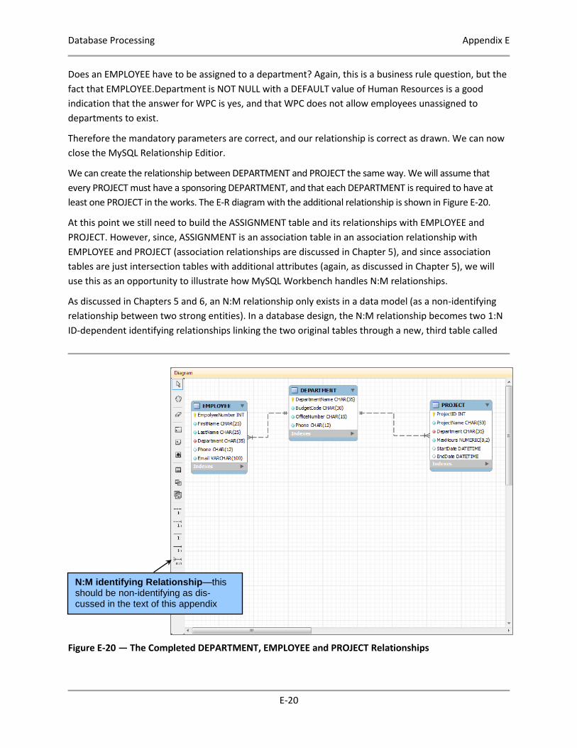
Does an EMPLOYEE have to be assigned to a department? Again, this is a business rule question, but the
fact that EMPLOYEE.Department is NOT NULL with a DEFAULT value of Human Resources is a good
indication that the answer for WPC is yes, and that WPC does not allow employees unassigned to
departments to exist.
Therefore the mandatory parameters are correct, and our relationship is correct as drawn. We can now
close the MySQL Relationship Editior.
We can create the relationship between DEPARTMENT and PROJECT the same way. We will assume that
every PROJECT must have a sponsoring DEPARTMENT, and that each DEPARTMENT is required to have at
least one PROJECT in the works. The E-R diagram with the additional relationship is shown in Figure E-20.
At this point we still need to build the ASSIGNMENT table and its relationships with EMPLOYEE and
PROJECT. However, since, ASSIGNMENT is an association table in an association relationship with
EMPLOYEE and PROJECT (association relationships are discussed in Chapter 5), and since association
tables are just intersection tables with additional attributes (again, as discussed in Chapter 5), we will
use this as an opportunity to illustrate how MySQL Workbench handles N:M relationships.
As discussed in Chapters 5 and 6, an N:M relationship only exists in a data model (as a non-identifying
relationship between two strong entities). In a database design, the N:M relationship becomes two 1:N
ID-dependent identifying relationships linking the two original tables through a new, third table called
Figure E-20 — The Completed DEPARTMENT, EMPLOYEE and PROJECT Relationships
N:M identifying Relationship—this should be non-identifying as dis-cussed in the text of this appendix

Database Processing Appendix E
E-21
an intersection table. However, MySQL Workbench only builds database designs, and will automatically
create the intersection table with the two 1:N relationships whenever we specify an N:M relationship.
Creating a N:M Nonidentifying Relationship Between Two Tables:
1. Click the N:M identifying Relationship button, then click the EMPLOYEE table, and then click the
PROJECT table.
2. As shown in Figure E-21, the MySQL Workbench creates an intersection table named
EMPLOYEE_has_PROJECT, and places it in the E-R diagram together with two 1:N ID-dependent
identifying relationships between (1) EMPLOYEE_has_PROJECT and EMPLOYEE, and (2)
EMPLOYEE_has_PROJECT and PROJECT.
We have just demonstrated that the MySQL Workbench can only create database designs.
Now we simply have to do some editing in the MySQL Table Editor to convert the intersection table into
an association table:
Change the table name to ASSIGNMENT.
Change the primary key attribute names to EmployeeNumber and ProjectID.
Add the HoursWorked attribute.
What about the relationship parameters? We will assume that every project has to have at least one
employee assigned to it, and that every empoyee has to work on at least one project. Therefore the
minimum cardinalities are correct as created. The final E-R diagram is shown in Figure B-22. And that
completes our introduction to the database design capabilites of the MySQL Workbench.
3. Save the WPC-Database-Design in the MySQL Workbench, and close the EER Diagram window.
4. Close the MySQL Model window.
5. Close the MySQL Workbench.
Figure E-21 — The Completed Set of Relationships
EMPLOYEE_has_PROJECT intersection table with two I:N ID-dependent identifying rela-tionships

Database Processing Appendix E
E-22
Figure E-22 — The Completed E-R Diagram
Key Terms
1:1 Identifying Relationship 1:1 Non-identifying Relationship
1:N Identifying Relationship 1:N Non-identifying Relationship
N:M Identifying Relationship Data model
Database design extended entity-relationship
MySQL Connector/ODBC MySQL Community Server
MySQL Installer for Windows MySQL Workbench
Object browser ODBC Driver
Open Database Connectivity (OBDC) Place a New Table button
Place a Relationship Using Existing Columns
button
Review Questions
E.1 What is MySQL?
E.2 What is the MySQL Connector/ODBC?
E.3 What is the MySQL Workbench?
E.4 What are two purposes of the MySQL Workbench?
E.5 The MySQL Workbench creates “database models”. What is a data model? What is a
database design? Which does MySQL Workbench create?

Database Processing Appendix E
E-23
E.6 How do you create a new E-R diagram in the MySQL Workbench?
E.7 How do you create a table in an E-R diagram?
E.8 How do you create a 1:N non-identifying relationship in an E-R diagram?
E.9 How does the MySQL Workbench handle N:M relationships?
Exercises
E.10 If you haven’t already done so, download and install the MySQL Workbench.
E.11 A database design for the Highline University database is shown in Figure 6-27. In the
MySQL Workbench, create a new ERR Model named HU-Database-Design. Recreate the
database design shown in Figure 6-27 in this drawing.
E.12 The database design for the VRG database is shown in Figure 6-37. In the MySQL
Workbench, create a new ERR Model drawing named VRG-Database-Design. Recreate
the database design shown in Figure 6-37 in this drawing.