online book shoppingmain srs final(1)
TRANSCRIPT

Online book shopping
Online Book Shopping

Abstract: Books shops are the integral part of any civilization. They are present in every culture since ages. This application emphasizes on the transaction going on between the customer and shop keeper. The customer approaches the shop keeper/ sales boy and places his order. The shop keeper forwards the order to sales boy who fetches the required goods from inventory. Then the shop keeper calculates bill and issues to the customer. The customer on paying the bill takes goods from the shop keeper. In turn, shop keeper fetches goods from supplier.
Customer places order to the shop keeper/sales boy· Sales boy collects goods and forwards them to shop keeper· Shop owner calculates bill and forwards to the customer· Customer on paying the bill receives goods from shop keeper· Shop keeper places order to supplier and receives goods
TEXTUAL ANALYSIS(a)ACTORSi. Customerii. Shop Owneriii. Sales boyiv. Supplier
(b)VERBSi. Customer:1. Places order to shop owner/sales boy2. Receives bill from shop owner3. Pay the bill4. Receive goods
ii. Shop Owner:1. Receives order from customer2. Forwards order to sales boy3. Receive goods from sales boy4. Calculates bill5. Receives payment6. Places orders to supplier7. Maintains inventory
iii. Supplier1. Receives order from shop owner2. Delivers goods to shop owner
Online Book Shopping

Software Requirement specification
IntroductionOverall Description of proposed system
System featuresOther Non-functional requirements
InterfacesUse case model
Online Book Shopping

1.Introduction
1.1 Purpose
The customer approaches the shop keeper/ sales boy and places his order. The shop keeper forwards the order to sales boy who fetches the required books from inventory. Then the shop keeper calculates bill and issues to the customer. The customer on paying the bill takes books from the shop keeper. In turn, shop keeper fetches books from supplier.
1.2 Document Conventions
The topographical conventions followed in the document are:1. Font used is Times New Roman.2. Main headings with font size 26 in bold with underline.3. Sub headings with font size 16.4. Regular paragraph writing in font size 12.
1.3 Intended Audience and Reading Suggestions
This document is intended and suggested reading for the developer and project managers who may add new features to the proposed project. Marketing staff who markets the project need to know the features of the project to market it. The project users or the customers, those who actually uses of the product, testers those who test the product, different database designers designing the interfacing databases to the have to go through this document.
1.4 Project Scope
The intended purpose of this project is to purchase the books by providing a convenient user interface. The benefits obtained from the project are that the convenient user interface online and ease of getting purchasing books online attract more number of customers to purchase the books and reduces the queues and the inconvenience caused to the customers due to the long queues.
1.5 References
The references used in designing this project are studying the purchase of books from the book shop.. The books can be purchased online providing a convenient user interface.
1.6 Definitions and Acronyms
Some of the following are the acronyms used in this project
Online Book Shopping

1. TCP/IP: Transmission Control Protocol/Internet Protocol
2. HTTP: Hypertext Transfer Protocol
3. HTML: Hypertext Markup Language
4. JSP: Java Server Pages
5. ID: Identification.
Online Book Shopping

2. Overall Description of Proposed System
2.1 Product Perspective
Earlier maintenance systems demanded high amount of time for managing the information as the data in the fields increased. Data updating was a tough task and retrieval also had the same effect. The origin of the product is to address all kinds of drawbacks or problems that are being encountered in the latter maintenance systems.
2.2 Product Features
The functions of the product can be categorized based on the distribution groups i.e. the administrator and the user, this category includes two types of users; users those who purchase the books online and the administrator provides the available books.
2.3 User Classes and Characteristics
Distinguishing user classes in the project is carried out on the basis of security level and expertise level. The user classes are categorized into administrator, Users.
2.4 Operating Environment
Front end of the application is developed using the Java Servlets. Due to the vast advantages the back end is maintained by the Microsoft Access Database
Operating System: Windows 2000 & above.
Software Requirements: Backend--- Microsoft Access Database Frontend---JSP
Hardware Platform: 256 MB and above Main Memory Hard disk Capacity - 40GB or more. Processor --- Pentium 4 and above or its equivalent.
Online Book Shopping

2.5 Design and Implementation Constraints
Certain issues limit the options available to the developers. The developer cannot provide a uniform access to all the user groups to maintain a friendly environment. As a primary measure they restrict the access to particular group to reduce the illegal access and security intrusion.
2.6 User Documentation
A complete user manual is provided with the end product to troubleshoot any problems that occur during the lifecycle of the tool. It comprises of vital information regarding the distribution of the access, backend information.
Online Book Shopping

3. System Features
3.1 Online book Shopping:
` 3.1.1 Description and Priority
System provides the user with the capability of purchasing the books online without queueing. It forms the basic functionality of the system and is of higher priority.
3.1.2 Stimulus/Response Sequences
When the user wants to purchase the books, he has to register first and the login into the system. He has to select the books which he wants to purchase and then gives an order. The sales person deliver the books when the credit card transaction completes.
Online Book Shopping

4.Other Nonfunctional Requirements
Usability
Our main criteria for making the system usable is the difficulty of performing each high frequency use case. Difficulty depends on the number of steps, the knowledge that the user must have at each step, the decisions that the user must make at each step, and the mechanics of each step. The user interface should be as familiar as possible to users who have used other web applications and Windows desktop applications.
Reliability
The product’s automatic upgrade feature will help us easily deploy defect fixes to the end-users. The user guide and product website will include troubleshooting guide and checklist of information to have at hand before contacting technical support.
Supportability
Supportability is our ability to provide cost effective technical support.
Performance Requirements
There is a better component design to get better performance at peak time. Each and every schema is normalized to the maximum normal form that can be attained to get better performance and low redundancy.
Security Requirements
Secure access of confidential data (user’s details) and constrained. access of information to the regular NetUsers who can purchase the books online. Only database administrator has the total access to the system and requires authentication by the system.
Software Quality Attributes
The project is designed based on a flexible service based architecture which will be helpful for future extension.
Online Book Shopping

5. Interfaces
User Interfaces
The project provides GUI forms to the users for easy understanding and application. The screens are designed in JAVA. The project offers different menus to the user to select from the given options.
Hardware Interfaces
Monitor screen – the software shall display information to the user via the monitor screen.
Mouse – the software shall interact with the movement of the mouse and the mouse buttons. The mouse shall activate areas for data input, command buttons and select options from menus.
Keyboard – the software shall interact with the keystrokes of the keyboard. The keyboard will input data into the active area of the database.
Software Interfaces
Windows is the operating system employed in this project as a software interface.
Online Book Shopping

6. Use case Model
Use cases are used during the requirements elicitation and analysis to represent functionality of the system. Use cases focus on the behavior of the system from an external point of view. In its simplest form, a use case can be described as a specific way of using the system from a user’s (actor’s) perspective. Use cases describe the
1. a pattern of behavior the system exhibits
2. a sequence of related transactions performed by an actor and the system
3. delivering something of value to the actor
Use cases provide a means to1. capture system requirements
2. communicate with the end users and domain experts
3. test the system
Use cases are best discovered by examining the actors and defining what the actor will be able to do with the system. Since all the needs of a system typically cannot be covered in one use case, it is usual to have a collection of use cases. Together this use case collection specifies all the ways of using the system.In a use case diagram there can be two kinds of relationships.
1. Association Relationship
An association provides a pathway for communication. The communication can be between use cases, actors, classes or interfaces. Associations are the most general of all relationships and consequentially the most semantically weak. If two objects are usually considered independently, the relationship is an association
NetUser login
2. Generalization Relationship
A generalize relationship is a relationship between a more general class or use case and a more specific class or use case. A generalization is shown as a solid-line path from the more specific element to a more general element. The tip or a generalization is a large hollow triangle pointing to the more general element.
Online Book Shopping
Subclass Superclass
3. Extend Relationship
An extend relationship is a stereotyped relationship that specifies how the functionality of one use case can be inserted into the functionality of another use case. Extend relationships between use cases are modeled as dependencies by using the Extend stereotype.
Extend relationships are important because they show optional functionality or system behavior. For example, Rational Rose allows you to place crop marks on printed diagrams.
4. Include Relationship
An include relationship is a stereotyped relationship that connects a base use case to an inclusion use case. An include relationship specifies how behavior in the inclusion use case is used by the base use case.
Include relationships are important because they represent that the inclusion use case functionality is used by the base use case.
6.1 Identifying Actors1. Netuser: He is the one who books tickets for the passengers who travel by the
train. In order to book ticket he need to get registered himself on the website to get a valid user-ID and Password to login into his account.
2. Passenger: He is the one who travels by the train using the ticket booked to him by the Netuser. He need tyo provide all the details of travel to the Netuser, in order to book his ticket.
3. Administrator: He is the one who manages the database and adds new services to the system.
6.2 Identifying Usecases
Online Book Shopping

1. aLogin: Login for administrator in order to manage the system.
2. uLogin: It is the basic functionality provided to the Netuser by the system in order to perform any other work on the system such booking, cancellation and enquiry. In order to Login into the system and perform some work a User need to provide a legitimate user-ID and password combination that is valid on the domain
3. register: In this the user is provided to get registered on the system in order to become a legitimate user and access the services provided by the system. In order to get registered a user has to provide the details necessary for the registration as asked by the system.
6.4 Usecase templates:
6.4.1 Name of the usecase:
a. login user id and password
b. Search for the items
c. purchase the items.
d. pays the bill
6.4.2 Participating actors:
a. Customer
b. Sales person
c. Sales manager
d. Casheir
Online Book Shopping

Book by name
Book by author
Magazines
Journals
News papers
login
search for books
Order the books
Enter the credit card details
Customer
receive the book
Online Book Shopping

Analysis Document
Sequence Diagrams
Collaboration Diagrams
State Chart Diagram
Online Book Shopping

7. Sequence Diagrams
Sequence diagrams represent the objects participating in the interaction horizontally and time vertically. Each column represents an object that participates in the interaction. Messages are shown by solid arrows. Labels on solid arrows represent message names and may contain arguments. Activations are depicted by the vertical rectangles. The actor who initiates the interaction is shown in the use case diagrams. If other actors communicate with the system during the use case, these actors are represented on the right hand side and can receive messages. Although for simplicity, interactions among objects and actors are uniformly represented as messages, the modeler should keep in mind that interactions between actors and the system are of a different nature than interactions among objects. These diagrams can be used to describe either an abstract sequence or concrete sequences. When describing all possible interactions, sequence diagrams also provide notations for conditionals and iterations. A condition on a message is denoted by an expression in brackets before the message name. If the expression is true the message is sent. Repetitive invocation of a message is denoted by a “*” before the message name.
User registration
User System Database
1: Enter details
2: Store
3: Stores
4: Acknowledgement
5: registered
Online Book Shopping

User Login
User System Database
1: Enter details
2: verify
3: Verifies
4: Acknowledgement
5: Logged in
Online Book Shopping

Make order
User System Database Bank
1: Search for books
2: get details
3: Checks
4: Acknowledgement
5: Display list
6: Select a book
7: Enter Card details
8: Check details
9: Checks
10: Acknowledgement
11: Deduct amount from account
12: deducts
13: Acknowledgement
14: receive book
Online Book Shopping

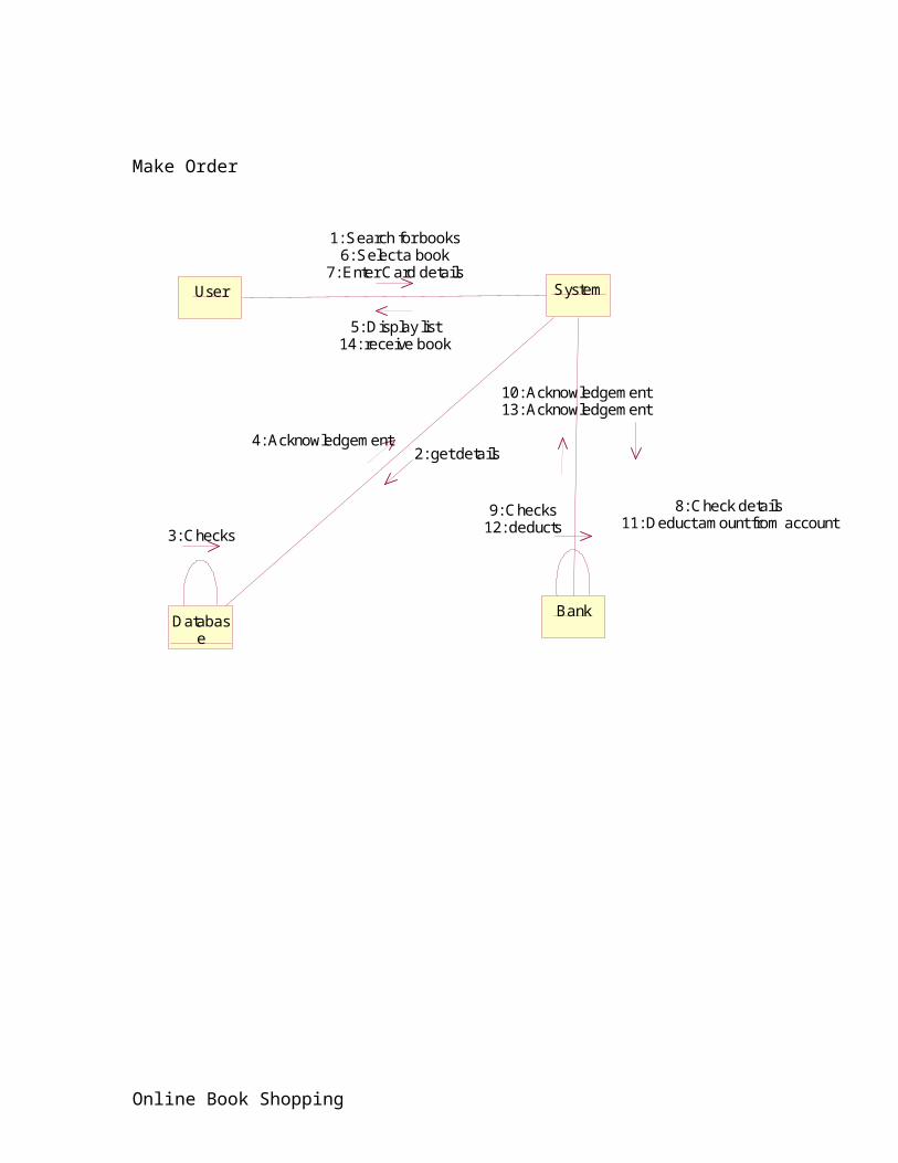
8. Collaboration Diagrams
A collaboration diagram also called a commutation diagram is an illustration of the relationships and interactions among software objects in the unified modeling language (UML). This concept although more than a decade old, has been refined as a model paradigm and evolved.
A collaboration diagram resembles a flowchart that portrays the roles, functionality and behavior of individual objects as well as the overall operation of the system in real time. Objects are shown as rectangles with naming labels inside. These labels are preceded by colons and may be underlined. The relationships between the objects are shown as arrows connecting the relevant rectangles along with labels that define message sequencing.
They are best suited to the portrayal of simple interactions among relatively small numbers of objects. As the number of objects and messages grow, a collaboration diagram can become difficult to read.
User Registration
5: registered
User System
Database
1: Enter details
2: Store3: Stores
4: Acknowledgement
User Login
Online Book Shopping

2: verify
User System
Database
1: Enter details
3: Verifies
4: Acknowledgement
5: Logged in
Make Order
Online Book Shopping

User System
Database
Bank
3: Checks
9: Checks12: deducts
1: Search for books6: Select a book
7: Enter Card details
5: Display list14: receive book
2: get details4: Acknowledgement
8: Check details11: Deduct amount from account
10: Acknowledgement13: Acknowledgement
Online Book Shopping
9. State Chart Diagrams
A state chart diagram is a graph that represents a state machine. State chart diagrams represent the behavior of entities capable of dynamic behavior by specifying its response to the receipt of event in stances.
State charts, often used more in real-time embedded systems than in information systems, show for a class, the order in which incoming calls to operations normally occur and the conditions under which the operations respond and the response. They are a class-centric view of system functionality, as opposed to sequence and collaboration diagrams which are a use case-centric view of functionality.
Purpose
To model dynamic aspect of a system.
To model life time of a reactive system.
Describe different states of an object during its life time.
To define a state machine to model states of an object.
Components of State Chart Diagrams
1. States - oblong boxes which indicate the stable states of the object between events
2. Transitions - the solid arrows which show possible changes of state
3. Events - the text on the transitions before the '/' showing the incoming call to the object interface which causes the change of state.
4. Conditions - a Boolean statement in square brackets which qualifies the event
5. Actions - the text after the '/' which defines the objects response to the transition between states.
6. Extra syntax which defines state centric functionality.
Online Book Shopping

User
Login
Search for books, magazines, journals, etc.,
Select the books
Order the books
Pay the bill by credit card transactions
receive the books
Online book Shop System
Online Book Shopping

view the books
View the order
Authenticate the user
check the credit card payments
deliver the boks
Online Book Shopping

System Design Document
Class DiagramDatabase DesignActivity Diagram
Component DiagramDeployment Diagram
Online Book Shopping
10. Class Diagram
Class diagrams describe the structure of the system in terms of classes and objects. Classes are abstractions that specify the attributes and behavior of set of objects. A class is a collection of objects that share a set of attributes that distinguish the objects as members of the collection. Objects are entities that encapsulate state and behavior. Each object is distinguishable from others.
Classes and objects are depicted by the boxes composed of three components. The top compartment displays the name of the class or object. The centre compartment displays its attributes and the bottom compartment displays the functions performed by it. The object names are underlined to indicate that they are instances. By convention, class name starts with uppercase letter and object name starts with lowercase letter. The type of an attribute is used to specify the valid range of the values the attribute can take. When attributes types are not essential to the definition of the system, attribute type decisions can be delayed until object design.
Inheritance
A very important concept in object-oriented design, inheritance, refers to the ability of one class (child class) to inherit the identical functionality of another class (super class), and then add new functionality of its own. To model inheritance on a class diagram, a solid line is drawn from the child class (the class inheriting the behavior) with a closed arrowhead (or triangle) pointing to the super class.
Association
There are 5 types of associations
Bi-directional (standard) associationAn association is a linkage between two classes. Associations are assumed to be
bi-directional -- in other words, both classes are aware of their relationship and of the other class -- unless you qualify the association as some other type of association. A bi-directional association is indicated by a solid line between the two classes. At either end of the line, we place a role same and a multiplicity value
Unidirectional associationA unidirectional association shows that two classes are related, but only one class
knows that the relationship exists. A unidirectional association is drawn as a solid line with an open arrowhead (not the closed arrowhead, or triangle, used to indicate inheritance) pointing to the known class.
Online Book Shopping

Association classIn modeling an association, there are times when you need to include another
class because it includes valuable information about the relationship. For this you would use an association class that you tie to the primary association. An association class (also called a drop class by my former professor) is represented like a normal class. The difference is that the association line between the primary classes intersects a dotted line connected to the association class.
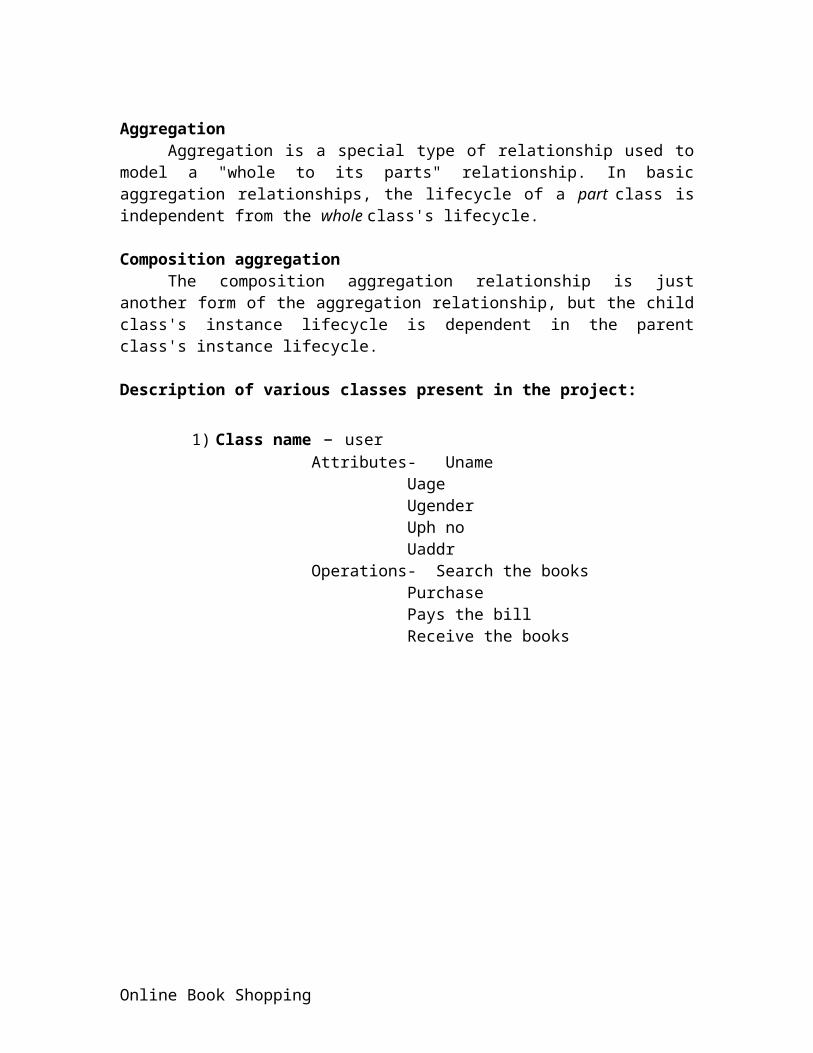
AggregationAggregation is a special type of relationship used to model a "whole to its parts"
relationship. In basic aggregation relationships, the lifecycle of a part class is independent from the whole class's lifecycle.
Composition aggregationThe composition aggregation relationship is just another form of the aggregation
relationship, but the child class's instance lifecycle is dependent in the parent class's instance lifecycle.
Description of various classes present in the project:
1) Class name – userAttributes- Uname
UageUgenderUph noUaddr
Operations- Search the booksPurchasePays the billReceive the books
Online Book Shopping

Books
Journals
Editions
Authors
Publications
UserUNameUAgeUAddressUEmail idUGender
Registration()Login()Search for books()order the books()enter the credit card detail()receive the books()
Book shop companyShopIdShopAddressLIst of books
collection of books()view availability()
DatabaseDBvalueIPAddressDBid
Maintain resources()
SystemIP Address
Communication()
Bank DatabaseBank Name
Verify the credentials()Transfer funds()
Online Book Shopping

11. Activity Diagram
Activity diagrams are diagram technique showing workflows of stepwise activities and actions, with support for choice, iteration and concurrency. In the UML, activity diagrams can be used to describe the business and operational step-by-step workflows of components in a system. An activity diagram shows the overall flow of control.
Activity diagrams should be used in conjunction with other modeling techniques such as interaction diagrams and state diagrams The main reason to use activity diagrams is to model the workflow behind the system being designed. Activity Diagrams are also useful for: analyzing a use case by describing what actions need to take place and when they should occur; describing a complicated sequential algorithm; and modeling applications with parallel processes.
Components of Activity Diagrams
Activity diagrams are constructed with a limited set of building blocks, consisting of:
Nodes - like initial node and activity final node, and.
Activity building blocks, and
Sometimes activity diagrams also contain building block for decision-making, but
it is questionable if these diagrams should be called activity diagram.
The starting point of the diagram is the initial node, which is mostly located on
top or on the left. And the ending of the diagram with an activity final node is on the
bottom or on the right. In between there can be zero, one or more activity building
blocks, which can be represented by rounded rectangles.
Online Book Shopping

login
search for books
Books Magazines
journals
Select the books
order the book
payment of bills
debit credit
receive the books
Verification
Valid userNo
Yes
receive the order
deliver the books
verify the bill
Bankonline book shop systemUser
Online Book Shopping

12. Component Diagram
Component diagrams provide a physical view of the current model. A component diagram shows the organizations and dependencies among software components, including source code components, binary code components, and executable components. These diagrams also show the externally-visible behavior of the components by displaying the interfaces of the components. Calling dependencies among components are shown as dependency relationships between components and interfaces on other components. Note that the interfaces actually belong to the logical view, but they can occur both in class diagrams and in component diagrams
Component diagrams contains· Component packages · Components · Interfaces · Dependency relationships
Component packages represent clusters of logically related components, or major pieces of your system. Component packages parallel the role played by logical packages for class diagrams. They allow you to partition the physical model of the system.
A Component represents a software module (source code, binary code, executable, DLL, etc.) with a well-defined interface. The interface of a component is represented by one or several interface elements that the component provides. Components are used to show compiler and run-time dependencies, as well as interface and calling dependencies among software modules. They also show which components implement a specific class.
A system may be composed of several software modules of different kinds. Each software module is represented by a component in the model. To distinguish different kinds of components from each other, stereotypes are used.
An interface specifies the externally-visible operations of a class and/or component, and has no implementation of its own. An interface typically specifies only a limited part of the behavior of a class or component.
A Dependency is a relationship between two model elements in which a change to one model element will affect the other model element. Use a dependency relationship to connect model elements with the same level of meaning. Typically, on class diagrams, a dependency relationship indicates that the operations of the client invoke operations of the supplier.
Online Book Shopping

User
login
search for books
payment
online book shop system
view the order
authenticate the users
deliver the books
Online Book Shopping

13. Deployment Diagram
A deployment diagram in the Unified Modeling Language serves to model the physical deployment of artifacts on deployment targets. Deployment diagrams show "the allocation of Artifacts to Nodes according to the Deployments defined between them." Deployment of an artifact to a node is indicated by placing the artifact inside the node.
Instances of nodes (and devices and execution environments) are used in deployment diagrams to indicate multiplicity of these nodes. For example, multiple instances of an application server execution environment may be deployed inside a single device node to represent application server clustering.
OBS system
Database
Server
TCP/IP
Online Book Shopping

Test Cases
14. Testing:
Online Book Shopping
Definition:
Testing is the process of finding differences between the expected behavior specified by the system model and the observed behavior of the implemented system.
Description:
It is a fault detection technique that tries to create failures or erroneous states in a planned way. This allows the developer to detect failures in the system before it is released to the customer. System testing is an expensive process but it is required in order to achieve a complete system. Generally the users tend to think that the process of providing that there do not exist, any errors in the system forms the testing part.
Types of Testing:
Unit Testing:
1. the most micro scale of testing.2. A unit is smallest software component3. Objects and methods4. Procedures and functions5. Performed by programmer and units are tested in isolation.6. Ensure that system is working according build design.7. Not to be confused with debugging.8. Also known as component, module testing
Integration Testing:
1. Testing of more than one (tested) unit together to determine if they function correctly.2. Focuses on interfaces of Communication between units3. It is done using the integration test design prepared during the architecture design.4. Helps assembling incrementally a whole system, ensuring the correct flow of data5. Done by developers/designers and testers in collaboration6. Also called Interface Testing or Assembly Testing.
System Testing:
Testing the system as a whole - Black-box type testing that is based on overall requirements specifications; covers all combined parts of a system.1. Ensures that system meets all functional and business requirements.2. Focus on verifying that specifications are met3. Validating that the system can be used for the intended purpose
Online Book Shopping

4. The system test design is derived from the system design documents and is used in this phase.5. It can involve a number of specialized types of tests to check performance, stress, documentation etc. Sometimes testing is automated using testing tools one by Independent testing groupAcceptance testing
1. To determine whether a system satisfies its acceptance criteria and business requirements or not.2. Similar to System testing in that the whole system is checked, but the important difference is the change in focus.3. Done by real business users.4. It enables the customer to determine whether to accept the system or not.
14.1 Test Cases:
A test case is a set of input data and expected results that exercises the component with the purpose of causing failures and detecting faults. Test cases are classified into black box test and white box test. Black box test focuses on input/output behavior of the component. White box test focuses on the internal structure of the components.
Module Name Find books.
Test Case Availability of books.
Input Author name, book name, etc.,
Output A page showing the books available with author name, book name etc.,
Module Name Cost Enquiry
Test Case To find the cost of the book
Input Book name
Output Cost of the book.
Online Book Shopping

Online Book Shopping

15. Conclusion
The project can be applied for any kind of online book shop with the simple modifications. The convenient user interface provided is easy to market and increases the scope of use of the book.
Online Book Shopping