online gas training at . fully train or re ... quickreferenceguide2014.2.2.pdf · gb-gas.co.uk gas...
TRANSCRIPT

Online Gas Training at www.gb-gas.co.uk. Fully Train or Re-Cap information for your assessment in your own time
and your own pace. Hours of videos and quiz questions Aim to Pass with GB-Gas.
This document and many more are available to download from
www.gb-gas.co.uk

gb-gas.co.uk GAS REFERENCE PACKAGE 2014v2 Aim To Pass With GB-Gas
Page | 2
Online Gas Training at www.gb-gas.co.uk.
Table of Contents Combustion ........................................................................................................................................................... 3
Procedure for carrying out a service with the aid of a Combustion Analyser. ............................................... 3
Appliance testing BS 7967-3 ................................................................................................................................ 4
Carrying out a room test with a Combustion Analyser. ................................................................................... 5
Pipe work inspection .......................................................................................................................................... 6
Re-establishing gas supplies ................................................................................................................................. 6
Testing for tightness (Using Gas) NEW SYSTEMS ......................................................................................... 7
Air testing .............................................................................................................................................................. 7
Testing for tightness (Using Gas) Existing Systems .......................................................................................... 8
Testing for tightness (Using Gas) Maximum Operating Pressure (MOP) greater than 75 MB ................... 9
Tightness testing Flow Chart ............................................................................................................................. 10
Ventilation ........................................................................................................................................................... 11
Meter Standing and Working Pressure ............................................................................................................ 13
Inlet working pressure ....................................................................................................................................... 13
Burner pressure .................................................................................................................................................. 13
Heat Inputs And Gas Rates. .............................................................................................................................. 14
Gas Rate Tables .................................................................................................................................................. 15
Gas safety devices and Controls ........................................................................................................................ 16
Additional Info for Cooker Controls ................................................................................................................ 20
Unsafe situations ................................................................................................................................................. 21
Flue inspection .................................................................................................................................................... 21
Room sealed flues................................................................................................................................................ 21
FLUE TESTING ................................................................................................................................................. 22
SPILLAGE TESTING ....................................................................................................................................... 23
Spillage Testing for room sealed appliances ..................................................................................................... 24
Positive Fan Pressure ......................................................................................................................................... 24
Appliance list ....................................................................................................................................................... 24
Flue Termination Points..................................................................................................................................... 25
Condensation and pluming. ............................................................................................................................... 26
Typical Gas Component Faults on Central Heating Boilers and Circulators ............................................... 27
Typical Gas Component Faults On ................................................................................................................... 28
Cookers ................................................................................................................................................................ 28
Typical Gas Component Faults On ................................................................................................................... 29
Space Heating (gas fires) .................................................................................................................................... 29
Typical Gas Component Faults On ................................................................................................................... 30
Warm Air Units. ................................................................................................................................................. 30
Typical Gas Component Faults On ................................................................................................................... 31
Volume and purge calculations for large installations .................................................................................... 32
Pipe work sizing .................................................................................................................................................. 33
Notes: ................................................................................................................................................................... 34
gb-gas.co.uk GAS REFERENCE PACKAGE 2014v2 Aim To Pass With GB-Gas
Page | 3
Hours of videos and quiz questions @ www.gb-gas.co.uk
Combustion See www.gb-gas.co.uk for more details.
Visual inspection
The main reasons for incomplete combustion 1. Lack of oxygen (soft yellow flames) 2. Incorrect burner pressure (over gassed / under gassed) 3. Flame impingement (flame chilling) A good pre-aerated flame should be bright blue with a strong inner and outer cone, and above all will have a roar. If there is any yellow in the flame then it is incorrect. (Do not mistake yellow for orange, as orange flames are usually dust being burnt.)
Procedure for carrying out a service with the aid of a Combustion
Analyser.
1. Carry out the service as per manufacturer’s instructions
Tightness test, clean and inspect.
2. If the appliance is range rated turn to maximum setting
Traditional boilers adjust to max burner pressure.
Combination boiler on hot water mode or chimney sweep mode.
Condensing boilers check manufacturer’s instructions.
All other appliances burner(s) on full.** **Be aware that checking a eye level grill when the hob burners are on will cause
incomplete combustion on the grill.
3. Take flue gas analysis
If acceptable: Reset to original burner pressure / gas rate and retest if ok Then conduct:
Flue and spillage test
Check safety controls.
Ventilation.
Confirm safe operation
If unacceptable: If possible rectify fault(s) then re test If not possible follow the unsafe situations guidelines.
At Risk for flued appliances
Immediately Dangerous for Flueless appliances.
4. Complete job documentation
If using a flue gas analyser acceptable readings vary depending on the appliance type. Consult manufacturers’ instructions. If the manufacturer supplies a Co2 reading only then make sure you are very close to that reading.

gb-gas.co.uk GAS REFERENCE PACKAGE 2014v2 Aim To Pass With GB-Gas
Page | 4
Online Gas Training at www.gb-gas.co.uk.
Appliance testing BS 7967-3 APPLIANCE TYPE CO/CO2 RATIO
Back boiler unit Boiler 0.008
In combination with fire
0.020
Central heating boiler 0.008
Hot water circulator 0.010
Flued space heater 0.020 (check man instructions)
Flueless space heater 0.001
Water heater flued and Flueless 0.020
Warm air heater 0.008
Flueless cooker Oven 0.008
Hob Visual inspection of flames
Grill (CE marked) 0.010
Grill (No CE mark) 0.020
Range oven flued 0.020
Refrigerator (LPG) 0.007
Tumble drier Flued 0.010
Flueless 0.001
Gas lights (LPG) 0.020
Maximum Carbon Monoxide in a Flue (CO) = 350ppm Any ratios above these readings maybe through, misuse, lack of maintenance, damage or aging. Make sure the probe is placed correctly:
Open flued: centre of the flue, or 200mm inside the draught diverter. Room sealed: From the manufacturers test point or 200mm inside the flue duct from outside Flueless appliances: On the flue outlet using the spreader bar tester. The appliance has run for 5 mins. Monitor the Co reading carefully if this starts rising quickly then remove the tester as you may damage the equipment.
If you don’t get the reading you are looking for let it run for a further 10 mins and retest. A full clean and check or repair of the appliance is essential and then re-tested. If it is not possible to achieve these levels then the appliance should be regarded as At Risk for flued appliances and Immediately Dangerous for Flueless appliances.
COMBUSTION
ANALYSER
Natural gas
Co…. 21 O2… 4.8
Co2...8.9
C
Most analysers work out ratios automatically. The
calculation is: 𝐶°/𝐶°2 𝑟𝑎𝑡𝑖𝑜 = 𝐶°
(𝐶°2 ×10,000)
gb-gas.co.uk GAS REFERENCE PACKAGE 2014v2 Aim To Pass With GB-Gas
Page | 5
Hours of videos and quiz questions @ www.gb-gas.co.uk
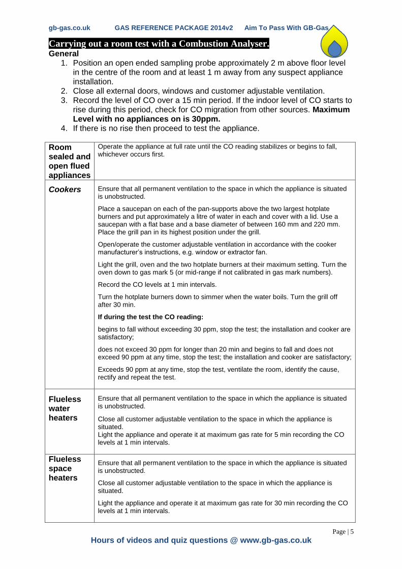
Carrying out a room test with a Combustion Analyser. General
1. Position an open ended sampling probe approximately 2 m above floor level in the centre of the room and at least 1 m away from any suspect appliance installation.
2. Close all external doors, windows and customer adjustable ventilation. 3. Record the level of CO over a 15 min period. If the indoor level of CO starts to
rise during this period, check for CO migration from other sources. Maximum Level with no appliances on is 30ppm.
4. If there is no rise then proceed to test the appliance.
Room sealed and open flued appliances
Operate the appliance at full rate until the CO reading stabilizes or begins to fall, whichever occurs first.
Cookers
Ensure that all permanent ventilation to the space in which the appliance is situated is unobstructed.
Place a saucepan on each of the pan-supports above the two largest hotplate burners and put approximately a litre of water in each and cover with a lid. Use a saucepan with a flat base and a base diameter of between 160 mm and 220 mm. Place the grill pan in its highest position under the grill.
Open/operate the customer adjustable ventilation in accordance with the cooker manufacturer’s instructions, e.g. window or extractor fan.
Light the grill, oven and the two hotplate burners at their maximum setting. Turn the oven down to gas mark 5 (or mid-range if not calibrated in gas mark numbers).
Record the CO levels at 1 min intervals.
Turn the hotplate burners down to simmer when the water boils. Turn the grill off after 30 min.
If during the test the CO reading:
begins to fall without exceeding 30 ppm, stop the test; the installation and cooker are satisfactory;
does not exceed 30 ppm for longer than 20 min and begins to fall and does not exceed 90 ppm at any time, stop the test; the installation and cooker are satisfactory;
Exceeds 90 ppm at any time, stop the test, ventilate the room, identify the cause, rectify and repeat the test.
Flueless water heaters
Ensure that all permanent ventilation to the space in which the appliance is situated is unobstructed.
Close all customer adjustable ventilation to the space in which the appliance is situated. Light the appliance and operate it at maximum gas rate for 5 min recording the CO levels at 1 min intervals.
Flueless space heaters
Ensure that all permanent ventilation to the space in which the appliance is situated is unobstructed.
Close all customer adjustable ventilation to the space in which the appliance is situated.
Light the appliance and operate it at maximum gas rate for 30 min recording the CO levels at 1 min intervals.

gb-gas.co.uk GAS REFERENCE PACKAGE 2014v2 Aim To Pass With GB-Gas
Page | 6
Online Gas Training at www.gb-gas.co.uk.
Pipe work inspection See www.gb-gas.co.uk for more details.
Common faults found on the meter installation:
Valve handle missing
Valve handle drops to on position
On / off label missing
Incorrect materials at meter
Incorrect or no telephone number
No emergency procedures label
No governor on primary meter
Governor not sealed
Common faults found on pipework installation:
No 10mm² bonding within 600mm of
the meter
To close to electric meters or outlets
(150mm)
To close to electric cables or conduits
(25mm)
Pipework inappropriately
supported
Incorrect sleaving methods
Incorrect materials used in pipework
Incorrect fittings used in pipework
Unsatisfactory workmanship
Re-establishing gas supplies
This checklist should be conducted every time the gas has been turned off. Even if only conducting a tightness test.
1. A visual check on the pipework installation
2. A visual check of the appliances should be made
3. Visual check & Calculate the ventilation requirements for the installation
4. Test for Tightness
5. Purge the meter from the furthest practical point Purge volume = 5x the meter badge capacity for installations with pipe up to 28mm e.g. ( imperial meter(ft³) = 5x 0.071ft³ = 0.355ft³) (metric meter(M³) = 5x 0.002m³ = 0.010m³) If there is pipework greater than 28mm or a meter bigger than a 6m capacity a calculation must be used U16 meter Purge volume = pipework length x volume of 1m length x 1.1 (for fittings) x 1.5 plus meter purge volume. Eg 3 m of 35mm pipe plus a U16 meter... 3 x 0.00084 x 1.1 + 0.024 x1.5 =0.042 m³.
See page 32 or IGEUP1B FOR MORE DETAIL or visit gb-gas.co.uk
Material and nominal size of pipe Volume of 1m length of pipe
Steel / stainless steel Copper
15mm ½ 0.00024 (m³) 15mm 0.00014 (m³)
20mm ¾ 0.00046 (m³) 22mm 0.00032 (m³)
25mm 1 0.00064 (m³) 28mm 0.00054 (m³)
32mm 1¼ 0.0011 (m³) 35mm 0.00084 (m³)
6. Purge the remaining sections of the installation (light and detect method)
7. Re-light each appliance in turn checking that all user controls are working satisfactorily
8. Check all open flued appliances for spillage
9. Inform customer on appliance use and gas safety
gb-gas.co.uk GAS REFERENCE PACKAGE 2014v2 Aim To Pass With GB-Gas
Page | 7
Hours of videos and quiz questions @ www.gb-gas.co.uk
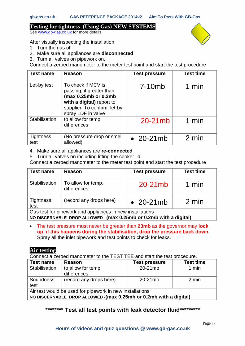
Testing for tightness (Using Gas) NEW SYSTEMS See www.gb-gas.co.uk for more details.
After visually inspecting the installation 1. Turn the gas off 2. Make sure all appliances are disconnected 3. Turn all valves on pipework on. Connect a zeroed manometer to the meter test point and start the test procedure
Test name
Reason
Test pressure Test time
Let-by test To check if MCV is passing, if greater than (max 0.25mb or 0.2mb with a digital) report to supplier. To confirm let-by spray LDF in valve
7-10mb 1 min
Stabilisation to allow for temp. differences
20-21mb 1 min
Tightness test
(No pressure drop or smell allowed)
20-21mb 2 min
4. Make sure all appliances are re-connected 5. Turn all valves on including lifting the cooker lid. Connect a zeroed manometer to the meter test point and start the test procedure
Test name
Reason
Test pressure Test time
Stabilisation To allow for temp. differences
20-21mb 1 min
Tightness test
(record any drops here)
20-21mb 2 min
Gas test for pipework and appliances in new installations NO DISCERNABLE DROP ALLOWED –(max 0.25mb or 0.2mb with a digital)
The test pressure must never be greater than 23mb as the governor may lock up, if this happens during the stabilisation, drop the pressure back down. Spray all the inlet pipework and test points to check for leaks.
Air testing Connect a zeroed manometer to the TEST TEE and start the test procedure.
Test name Reason Test pressure Test time
Stabilisation to allow for temp. differences
20-21mb 1 min
Soundness test
(record any drops here) 20-21mb 2 min
Air test would be used for pipework in new installations NO DISCERNABLE DROP ALLOWED -(max 0.25mb or 0.2mb with a digital)
******** Test all test points with leak detector fluid*********

gb-gas.co.uk GAS REFERENCE PACKAGE 2014v2 Aim To Pass With GB-Gas
Page | 8
Online Gas Training at www.gb-gas.co.uk.
Testing for tightness (Using Gas) Existing Systems
After visually inspecting the installation 1. Turn the gas off 2. Make sure all appliances are connected 3. Turn all valves on pipework on. Connect a zeroed manometer to the meter test point and start the test procedure
Test name
Reason
Test pressure Test time
Let-by test To check if MCV is passing, if greater than (max 0.25mb or 0.2mb with a digital) report to supplier. To confirm let-by spray LDF in valve
7-10mb 1 min
Stabilisation To allow for temp. differences
20-21mb 1 min
Soundness test
(see information below) 20-21mb 2 min
If there is no discernable pressure drop in the system and no smell of gas then the system has passed.
If there is a drop in the system then all the appliances must be isolated and the pipework tested on its own (no discernable drop is allowed in the pipework)
If the drop is at an appliance and within the limits set (below) and no gas can be smelled, then the system may be passed.
The test pressure must never be greater than 23mb as the governor may lock up, if so you will have to spray all the inlet pipework to check for leaks.
Maximum drop allowed
U6 meter 4mb over 2min* or 2.5 mb if there is pipe work greater than 28mm
E6 meter or No meter
8mb over 2min* 4 mb if there is pipe work greater than 28mm
U16 meter 1mb over 2 min* even if the pipe is greater than 28 mm
* in any situation if the recorded drop is in the pipework it is an immediate fail * if there is a sell of gas the installation is an immediate fail
******** Test all test points with leak detector fluid*********

gb-gas.co.uk GAS REFERENCE PACKAGE 2014v2 Aim To Pass With GB-Gas
Page | 9
Hours of videos and quiz questions @ www.gb-gas.co.uk
Testing for tightness (Using Gas) Maximum Operating Pressure (MOP) greater than 75 MB
After visually inspecting the installation 1. Turn the gas off 2. Make sure all appliances are connected and no pilot lights 3. Turn all valves on pipework on. Connect a zeroed manometer to the meter test point and start the test procedure
Test name
How Reason
Test pressure
Test time
Let-by test for Meter Control Valve (A)
Take the system up to standing pressure. Close meter control valve. Release pressure e.g. (by opening a cooker) Hold open regulator valve and observe.
To check if MCV is passing, if greater than (max 0.25mb) report to supplier. To confirm let-by spray LDF in valve
Approx.
7-10mb
1 min
Let-by test for Regulator lock out (B)
Release the regulator valve pressure should increase slightly. Open meter control valve and observe.
to check if regulator is passing on lock out, if greater than (max 0.25mb) report to supplier
Approx.
7-10mb
1 min
Stabilisation Raise pressure to 19 mb close meter control valve
To allow for temp. differences
19mb 1 min
Soundness test
Observe (No discernable pressure drop or smell allowed)
19mb 2 min
No discernable drop is any drop greater than 0.25mb
The test pressure must never be greater than 19mb as the governor may lock up,
Because the inlet pipework is subjected to pressures up to 2 bar you must spray all the inlet pipework to check for leaks.
Maximum drop allowed
U6 meter 4mb over 2min* or 2.5 mb if there is pipe work greater than 28mm
E6 meter or No meter
8mb over 2min* 4 mb if there is pipe work greater than 28mm
U16 meter 1mb over 2 min* even if the pipe is greater than 28 mm
* in any situation if the recorded drop is in the pipework it is an immediate fail * if there is a sell of gas the installation is an immediate fail
******** Test all test points with leak detector fluid*********
gb-gas.co.uk GAS REFERENCE PACKAGE 2014v2 Aim To Pass With GB-Gas
Page | 10
Online Gas Training at www.gb-gas.co.uk.
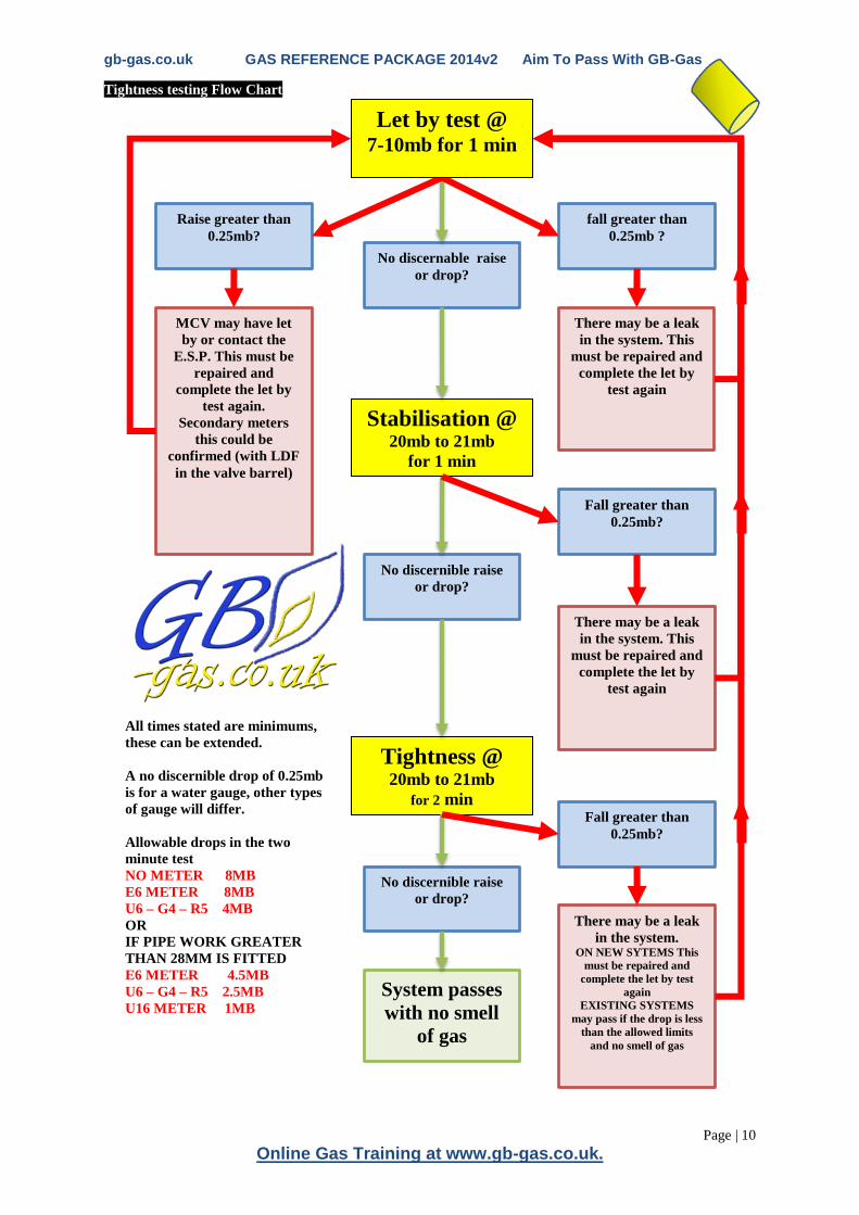
Tightness testing Flow Chart
Raise greater than
0.25mb?
No discernable raise
or drop?
fall greater than
0.25mb ?
MCV may have let
by or contact the
E.S.P. This must be
repaired and
complete the let by
test again.
Secondary meters
this could be
confirmed (with LDF
in the valve barrel)
There may be a leak
in the system. This
must be repaired and
complete the let by
test again
Stabilisation @ 20mb to 21mb
for 1 min
Tightness @ 20mb to 21mb
for 2 min
No discernible raise
or drop?
No discernible raise
or drop?
There may be a leak
in the system. This
must be repaired and
complete the let by
test again
Fall greater than
0.25mb?
Fall greater than
0.25mb?
There may be a leak
in the system. ON NEW SYTEMS This
must be repaired and
complete the let by test
again
EXISTING SYSTEMS
may pass if the drop is less
than the allowed limits
and no smell of gas
System passes
with no smell
of gas
Let by test @ 7-10mb for 1 min
All times stated are minimums,
these can be extended.
A no discernible drop of 0.25mb
is for a water gauge, other types
of gauge will differ.
Allowable drops in the two
minute test
NO METER 8MB
E6 METER 8MB
U6 – G4 – R5 4MB
OR
IF PIPE WORK GREATER
THAN 28MM IS FITTED
E6 METER 4.5MB
U6 – G4 – R5 2.5MB
U16 METER 1MB
gb-gas.co.uk GAS REFERENCE PACKAGE 2014v2 Aim To Pass With GB-Gas
Page | 11
Hours of videos and quiz questions @ www.gb-gas.co.uk
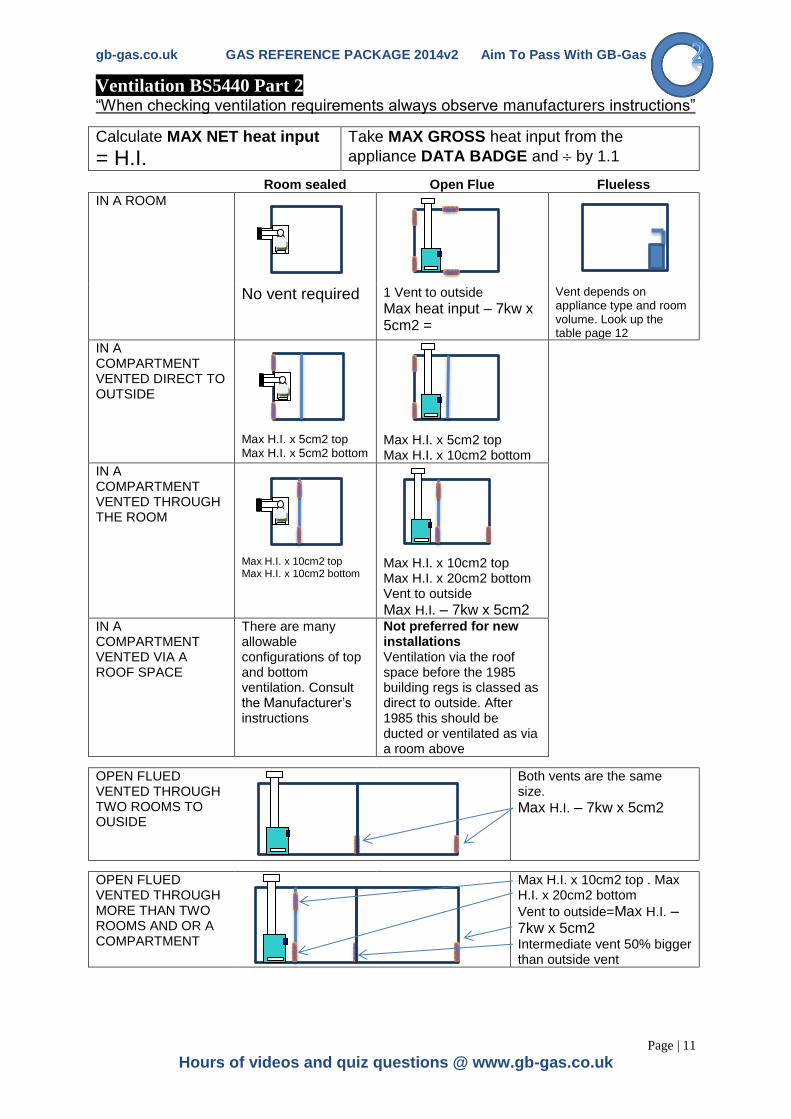
Ventilation BS5440 Part 2 “When checking ventilation requirements always observe manufacturers instructions”
Calculate MAX NET heat input
= H.I. Take MAX GROSS heat input from the
appliance DATA BADGE and by 1.1
Room sealed Open Flue Flueless
IN A ROOM
No vent required 1 Vent to outside
Max heat input – 7kw x 5cm2 =
Vent depends on appliance type and room volume. Look up the table page 12
IN A COMPARTMENT VENTED DIRECT TO OUTSIDE
Max H.I. x 5cm2 top Max H.I. x 5cm2 bottom
Max H.I. x 5cm2 top Max H.I. x 10cm2 bottom
IN A COMPARTMENT VENTED THROUGH THE ROOM
Max H.I. x 10cm2 top Max H.I. x 10cm2 bottom
Max H.I. x 10cm2 top Max H.I. x 20cm2 bottom Vent to outside
Max H.I. – 7kw x 5cm2
IN A COMPARTMENT VENTED VIA A ROOF SPACE
There are many allowable configurations of top and bottom ventilation. Consult the Manufacturer’s instructions
Not preferred for new installations Ventilation via the roof space before the 1985 building regs is classed as direct to outside. After 1985 this should be ducted or ventilated as via a room above
OPEN FLUED VENTED THROUGH TWO ROOMS TO OUSIDE
Both vents are the same size.
Max H.I. – 7kw x 5cm2
OPEN FLUED VENTED THROUGH MORE THAN TWO ROOMS AND OR A COMPARTMENT
Max H.I. x 10cm2 top . Max H.I. x 20cm2 bottom
Vent to outside=Max H.I. – 7kw x 5cm2
Intermediate vent 50% bigger than outside vent
gb-gas.co.uk GAS REFERENCE PACKAGE 2014v2 Aim To Pass With GB-Gas
Page | 12
Online Gas Training at www.gb-gas.co.uk.
OPEN FLUED additional
TWO Open flued GAS FIRES in the same room (less than 14kW)
additional ventilation may not be required
TWO Open flued GAS FIRES in the same room (greater than 14kW)
Add heat inputs together and calculate as for one open flued appliance in a room
IF flue or spillage test fails additional ventilation is required
Two or more DFE fires in a room 100cm2 for first then 135cm
2 for each additional
(extra 35cm2 is adventitious ventilation ie 7kw)
= 235cm2 for two DFE fires.
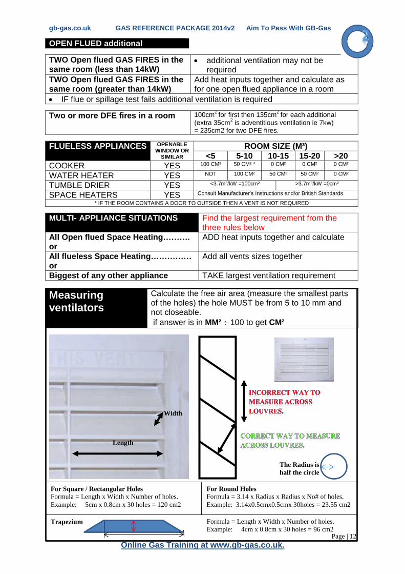
FLUELESS APPLIANCES OPENABLE WINDOW OR
SIMILAR
ROOM SIZE (M³)
<5 5-10 10-15 15-20 >20
COOKER YES 100 CM² 50 CM² * 0 CM² 0 CM² 0 CM²
WATER HEATER YES NOT 100 CM² 50 CM² 50 CM² 0 CM²
TUMBLE DRIER YES <3.7m³/kW =100cm² >3.7m³/kW =0cm²
SPACE HEATERS YES Consult Manufacturer’s Instructions and/or British Standards
* IF THE ROOM CONTAINS A DOOR TO OUTSIDE THEN A VENT IS NOT REQUIRED
MULTI- APPLIANCE SITUATIONS Find the largest requirement from the three rules below
All Open flued Space Heating………. or
ADD heat inputs together and calculate
All flueless Space Heating…………… or
Add all vents sizes together
Biggest of any other appliance TAKE largest ventilation requirement
Measuring ventilators
Calculate the free air area (measure the smallest parts of the holes) the hole MUST be from 5 to 10 mm and not closeable.
if answer is in MM² 100 to get CM²
Length
Width
For Square / Rectangular Holes
Formula = Length x Width x Number of holes.
Example: 5cm x 0.8cm x 30 holes = 120 cm2
For Round Holes
Formula = 3.14 x Radius x Radius x No# of holes.
Example: 3.14x0.5cmx0.5cmx 30holes = 23.55 cm2
The Radius is
half the circle
Trapezium Formula = Length x Width x Number of holes.
Example: 4cm x 0.8cm x 30 holes = 96 cm2

gb-gas.co.uk GAS REFERENCE PACKAGE 2014v2 Aim To Pass With GB-Gas
Page | 13
Hours of videos and quiz questions @ www.gb-gas.co.uk
Pressure testing
Meter Standing and Working Pressure
1. Connect a zeroed manometer to the meter test nipple.** 2. Turn on gas slowly and record STANDING PRESSURE (APPROX. 25mb) 3. Then turn on ONE appliance: 1.Cooker 3 hotplates.
2.Fire on full rate. 3.Boiler on full rate.* 4.Other appliance full rate.
*a range rated boiler may cause a problem, if using a combi. Use hot water mode 4. Record reading on the WORKING PRESSURE (must be from 19mb to 23mb) if
to high or to low contact gas supplier for primary meter, if it is a secondary meter adjust (screw down clockwise to increase pressure.)
**To read the manometer correctly add both legs together and divide by 2** If the meter is running at full rate (6m³/hr), with an inlet pressure of 19mb at the governor. The drop or (absorption) through the meter will be as much as 4mb.
Inlet working pressure
This test is prove the pipework is suitable in size and length with no blockages. 1. Connect a zeroed manometer to the boiler inlet test point. 2. Turn on the appliance and record the reading( only 1mb drop allowed through
the pipeline) see page 29 for more details e.g. working pressure at the meter : 21mb inlet working pressure : 20mb installation acceptable. **To read the manometer correctly add both legs together and divide by 2**
Burner pressure
This test is to prove that the appliance is burning within the limitations set by the manufacturer. 1. Connect a zeroed manometer to the boiler BURNER PRESSURE test point. 2. Turn on the appliance and record the reading (compare the reading against the
appliance data badge. The reading must be within the range) **To read the manometer correctly add both legs together and divide by 2**
******** Test all testpoints with leak detector fluid*********
STANDING PRESSURE at the meter (APPROX. 25mb)
Test method (see below)
WORKING PRESSURE (must be 21± 2 mb) AT THE
METER
Test method (see below)
APPLIANCE INLET
WORKING PRESSURE
(max 1mb drop form working
pressure at the meter)
APPLIANCE BURNER
PRESSURE (check
against appliance data
badge)
Multifunction control
gb-gas.co.uk GAS REFERENCE PACKAGE 2014v2 Aim To Pass With GB-Gas
Page | 14
Online Gas Training at www.gb-gas.co.uk.
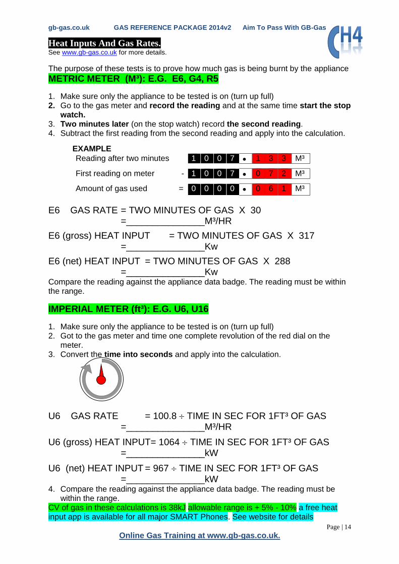
Heat Inputs And Gas Rates. See www.gb-gas.co.uk for more details.
The purpose of these tests is to prove how much gas is being burnt by the appliance
METRIC METER (M³): E.G. E6, G4, R5
1. Make sure only the appliance to be tested is on (turn up full) 2. Go to the gas meter and record the reading and at the same time start the stop
watch. 3. Two minutes later (on the stop watch) record the second reading. 4. Subtract the first reading from the second reading and apply into the calculation.
EXAMPLE
Reading after two minutes 1 0 0 7 1 3 3 M³
First reading on meter - 1 0 0 7 0 7 2 M³
Amount of gas used = 0 0 0 0 0 6 1 M³
E6 GAS RATE = TWO MINUTES OF GAS X 30 =_______________M³/HR
E6 (gross) HEAT INPUT = TWO MINUTES OF GAS X 317 =_______________Kw
E6 (net) HEAT INPUT = TWO MINUTES OF GAS X 288 =_______________Kw Compare the reading against the appliance data badge. The reading must be within the range.
IMPERIAL METER (ft³): E.G. U6, U16
1. Make sure only the appliance to be tested is on (turn up full) 2. Got to the gas meter and time one complete revolution of the red dial on the
meter. 3. Convert the time into seconds and apply into the calculation.
U6 GAS RATE = 100.8 TIME IN SEC FOR 1FT³ OF GAS =_______________M³/HR
U6 (gross) HEAT INPUT= 1064 TIME IN SEC FOR 1FT³ OF GAS =_______________kW
U6 (net) HEAT INPUT = 967 TIME IN SEC FOR 1FT³ OF GAS =_______________kW 4. Compare the reading against the appliance data badge. The reading must be
within the range. CV of gas in these calculations is 38kJ allowable range is + 5% - 10% a free heat input app is available for all major SMART Phones. See website for details

gb-gas.co.uk GAS REFERENCE PACKAGE 2014v2 Aim To Pass With GB-Gas
Page | 15
Hours of videos and quiz questions @ www.gb-gas.co.uk
Gas Rate Tables
gb-gas.co.uk GAS REFERENCE PACKAGE 2014v2 Aim To Pass With GB-Gas
Page | 16
Online Gas Training at www.gb-gas.co.uk.
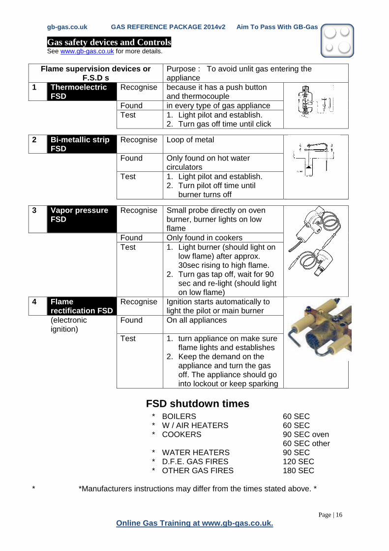
Gas safety devices and Controls See www.gb-gas.co.uk for more details.
Flame supervision devices or F.S.D s
Purpose : To avoid unlit gas entering the appliance
1 Thermoelectric FSD
Recognise because it has a push button and thermocouple
Found in every type of gas appliance
Test 1. Light pilot and establish. 2. Turn gas off time until click
2 Bi-metallic strip FSD
Recognise Loop of metal
Found Only found on hot water circulators
Test 1. Light pilot and establish. 2. Turn pilot off time until
burner turns off
3 Vapor pressure FSD
Recognise Small probe directly on oven burner, burner lights on low flame
Found Only found in cookers
Test 1. Light burner (should light on low flame) after approx. 30sec rising to high flame.
2. Turn gas tap off, wait for 90 sec and re-light (should light on low flame)
4 Flame rectification FSD
Recognise Ignition starts automatically to light the pilot or main burner
(electronic ignition)
Found On all appliances
Test 1. turn appliance on make sure flame lights and establishes
2. Keep the demand on the appliance and turn the gas off. The appliance should go into lockout or keep sparking
FSD shutdown times
* BOILERS 60 SEC * W / AIR HEATERS 60 SEC * COOKERS 90 SEC oven
60 SEC other * WATER HEATERS 90 SEC * D.F.E. GAS FIRES 120 SEC * OTHER GAS FIRES 180 SEC * *Manufacturers instructions may differ from the times stated above. *
gb-gas.co.uk GAS REFERENCE PACKAGE 2014v2 Aim To Pass With GB-Gas
Page | 17
Hours of videos and quiz questions @ www.gb-gas.co.uk
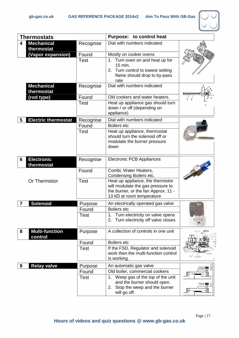
Thermostats Purpose: to control heat
4 Mechanical thermostat
Recognise Dial with numbers indicated
(Vapor expansion) Found Mostly on cooker ovens
Test 1. Turn oven on and heat up for 15 min.
2. Turn control to lowest setting flame should drop to by-pass rate
Mechanical thermostat
Recognise Dial with numbers indicated
(rod type) Found Old cookers and water heaters.
Test Heat up appliance gas should turn down / or off (depending on appliance)
5 Electric thermostat Recognise Dial with numbers indicated
Found Boilers etc
Test Heat up appliance, thermostat should turn the solenoid off or modulate the burner pressure down
6 Electronic thermostat
Recognise Electronic PCB Appliances
Found Combi, Water Heaters, Condensing Boilers etc.
Or Thermistor Test Heat up appliance, the thermistor will modulate the gas pressure to the burner, or the fan Approx. 11 -13 kΏ at room temperature
7 Solenoid Purpose An electrically operated gas valve
Found Boilers etc
Test 1. Turn electricity on valve opens 2. Turn electricity off valve closes
8 Multi-function control
Purpose A collection of controls in one unit
Found Boilers etc
Test If the FSD, Regulator and solenoid work then the multi-function control is working.
9 Relay valve Purpose An automatic gas valve
Found Old boiler, commercial cookers
Test 1. Weep gas of the top of the unit and the burner should open.
2. Stop the weep and the burner will go off.

gb-gas.co.uk GAS REFERENCE PACKAGE 2014v2 Aim To Pass With GB-Gas
Page | 18
Online Gas Training at www.gb-gas.co.uk.
10 Lid or Grill Door safety device
Purpose To turn off the burners, when the lid drops
Mechanical safety Found Cookers, (hotplates)
cut off Test 1. Turn on gas tap to hotplate. 2. Lower lid or close grill door and
gas should turn off
11 Gas tap Purpose To control the flow off gas safely
Found Cooker, fires ,etc
Test 1. tap locks in the off position 2. tap functions correctly
12 Atmospheric Sensing Device (ASD) (VSD)
Purpose To close down the open flued appliance automatically, if the appliance and flue operate incorrectly
Found All open flued appliances after 1998
Test 1. Light pilot. 2. Close air inlet hole and observe
flame (turn yellow)
13 Atmospheric Sensing Device / over heat
Purpose To close down the open flued appliance automatically, if the appliance and flue operate incorrectly
Thermocouple interrupter
Found On water heaters, Flued water heaters this is usually a overheat safety device. Flueless used as an ASD
Test Visual inspection to check wiring to thermocouple (no links) and check FSD
14 Regulator Purpose Adjuster screw to alter burner pressure
Found Boilers etc
Test 1. Attach manometer to test point 2. Adjust screw to alter pressure
15 Zero governor on a atmospheric burner
Purpose To compensate for the negative pressure caused by the fan, on the gas valve (this could pull more gas into the burner than intended)
Found Fan flued room sealed appliances with atmospheric burners
Test 1. Attach manometer to burner pressure test point
2. Turn appliance on when the fan comes on the manometer reads negative pressure, quickly going to positive pressure when the burner comes on.
gb-gas.co.uk GAS REFERENCE PACKAGE 2014v2 Aim To Pass With GB-Gas
Page | 19
Hours of videos and quiz questions @ www.gb-gas.co.uk
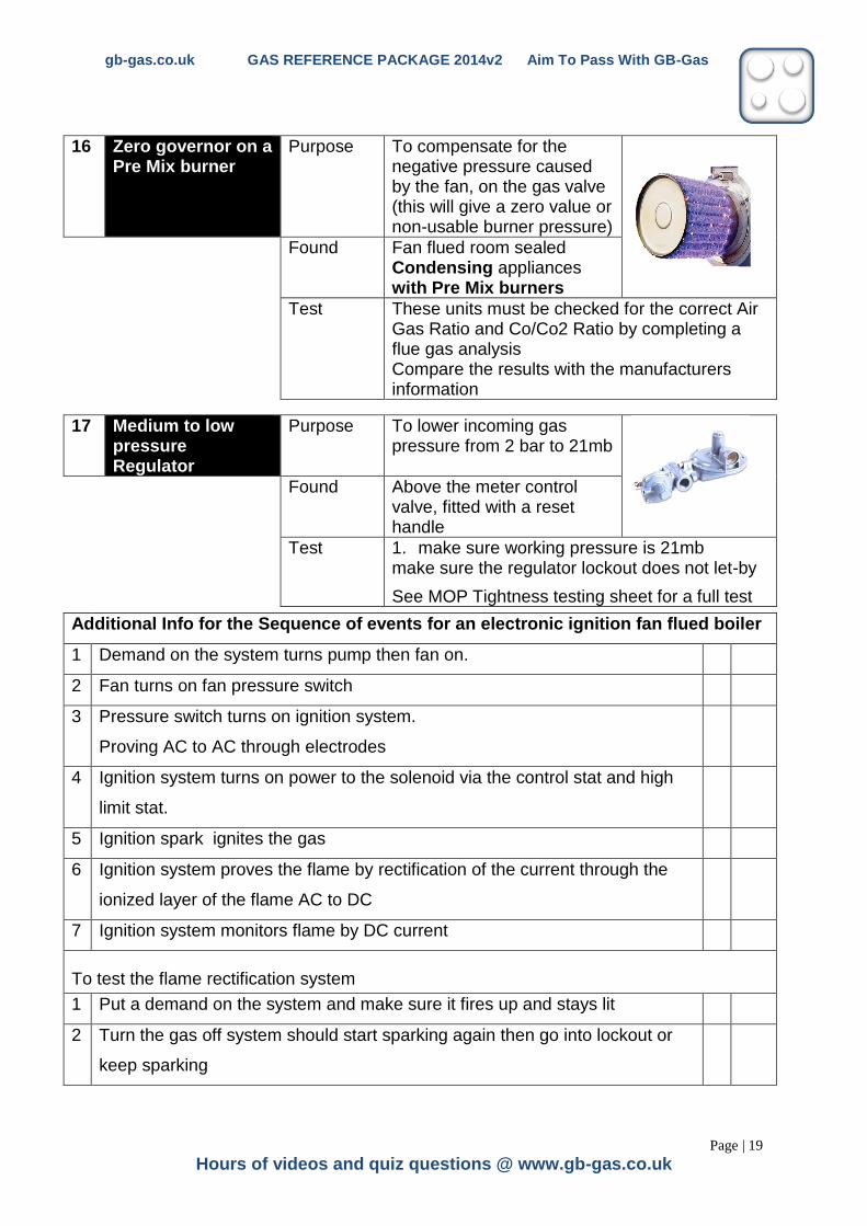
16 Zero governor on a Pre Mix burner
Purpose To compensate for the negative pressure caused by the fan, on the gas valve (this will give a zero value or non-usable burner pressure)
Found Fan flued room sealed Condensing appliances with Pre Mix burners
Test These units must be checked for the correct Air Gas Ratio and Co/Co2 Ratio by completing a flue gas analysis Compare the results with the manufacturers information
17 Medium to low pressure Regulator
Purpose To lower incoming gas pressure from 2 bar to 21mb
Found Above the meter control valve, fitted with a reset handle
Test 1. make sure working pressure is 21mb make sure the regulator lockout does not let-by
See MOP Tightness testing sheet for a full test
Additional Info for the Sequence of events for an electronic ignition fan flued boiler
1 Demand on the system turns pump then fan on.
2 Fan turns on fan pressure switch
3 Pressure switch turns on ignition system.
Proving AC to AC through electrodes
4 Ignition system turns on power to the solenoid via the control stat and high
limit stat.
5 Ignition spark ignites the gas
6 Ignition system proves the flame by rectification of the current through the
ionized layer of the flame AC to DC
7 Ignition system monitors flame by DC current
To test the flame rectification system
1 Put a demand on the system and make sure it fires up and stays lit
2 Turn the gas off system should start sparking again then go into lockout or
keep sparking
gb-gas.co.uk GAS REFERENCE PACKAGE 2014v2 Aim To Pass With GB-Gas
Page | 20
Online Gas Training at www.gb-gas.co.uk.
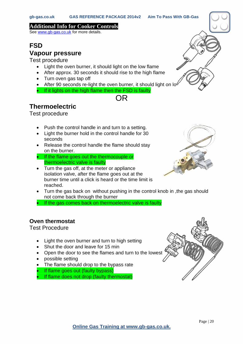
Additional Info for Cooker Controls See www.gb-gas.co.uk for more details.
FSD Vapour pressure
Test procedure Light the oven burner, it should light on the low flame
After approx. 30 seconds it should rise to the high flame
Turn oven gas tap off
After 90 seconds re-light the oven burner, it should light on low flame
If it lights on the high flame then the FSD is faulty
OR Thermoelectric Test procedure
Push the control handle in and turn to a setting.
Light the burner hold in the control handle for 30 seconds
Release the control handle the flame should stay on the burner.
If the flame goes out the thermocouple or thermoelectric valve is faulty
Turn the gas off, at the meter or appliance isolation valve, after the flame goes out at the burner time until a click is heard or the time limit is reached.
Turn the gas back on without pushing in the control knob in ,the gas should not come back through the burner
If the gas comes back on thermoelectric valve is faulty
Oven thermostat Test Procedure
Light the oven burner and turn to high setting
Shut the door and leave for 15 min
Open the door to see the flames and turn to the lowest
possible setting
The flame should drop to the bypass rate
If flame goes out (faulty bypass)
If flame does not drop (faulty thermostat)
gb-gas.co.uk GAS REFERENCE PACKAGE 2014v2 Aim To Pass With GB-Gas
Page | 21
Hours of videos and quiz questions @ www.gb-gas.co.uk
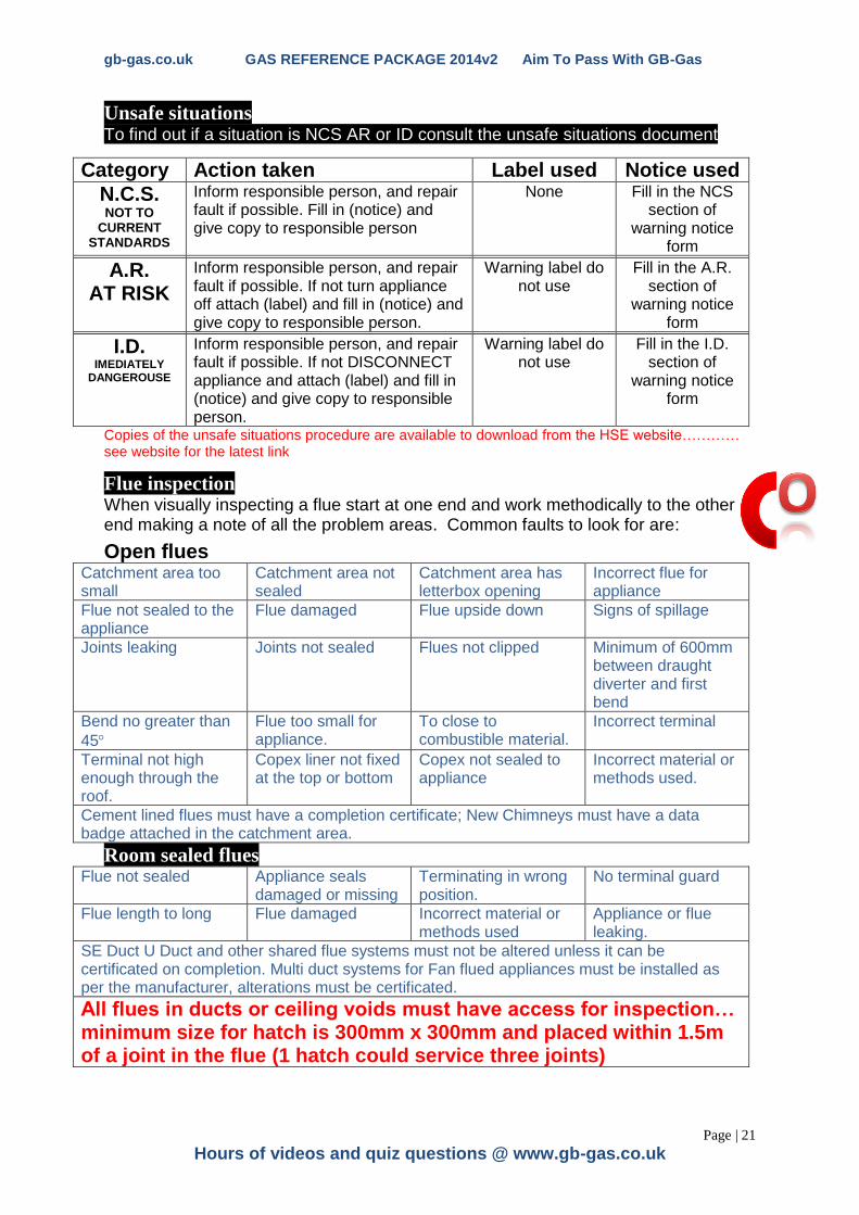
Unsafe situations
To find out if a situation is NCS AR or ID consult the unsafe situations document
Category Action taken Label used Notice used
N.C.S. NOT TO
CURRENT STANDARDS
Inform responsible person, and repair fault if possible. Fill in (notice) and give copy to responsible person
None Fill in the NCS section of
warning notice form
A.R. AT RISK
Inform responsible person, and repair fault if possible. If not turn appliance off attach (label) and fill in (notice) and give copy to responsible person.
Warning label do not use
Fill in the A.R. section of
warning notice form
I.D. IMEDIATELY
DANGEROUSE
Inform responsible person, and repair fault if possible. If not DISCONNECT appliance and attach (label) and fill in (notice) and give copy to responsible person.
Warning label do not use
Fill in the I.D. section of
warning notice form
Copies of the unsafe situations procedure are available to download from the HSE website………… see website for the latest link
Flue inspection When visually inspecting a flue start at one end and work methodically to the other end making a note of all the problem areas. Common faults to look for are:
Open flues Catchment area too small
Catchment area not sealed
Catchment area has letterbox opening
Incorrect flue for appliance
Flue not sealed to the appliance
Flue damaged Flue upside down Signs of spillage
Joints leaking Joints not sealed Flues not clipped Minimum of 600mm between draught diverter and first bend
Bend no greater than
45
Flue too small for appliance.
To close to combustible material.
Incorrect terminal
Terminal not high enough through the roof.
Copex liner not fixed at the top or bottom
Copex not sealed to appliance
Incorrect material or methods used.
Cement lined flues must have a completion certificate; New Chimneys must have a data badge attached in the catchment area.
Room sealed flues Flue not sealed Appliance seals
damaged or missing Terminating in wrong position.
No terminal guard
Flue length to long Flue damaged Incorrect material or methods used
Appliance or flue leaking.
SE Duct U Duct and other shared flue systems must not be altered unless it can be certificated on completion. Multi duct systems for Fan flued appliances must be installed as per the manufacturer, alterations must be certificated.
All flues in ducts or ceiling voids must have access for inspection… minimum size for hatch is 300mm x 300mm and placed within 1.5m of a joint in the flue (1 hatch could service three joints)
gb-gas.co.uk GAS REFERENCE PACKAGE 2014v2 Aim To Pass With GB-Gas
Page | 22
Online Gas Training at www.gb-gas.co.uk.
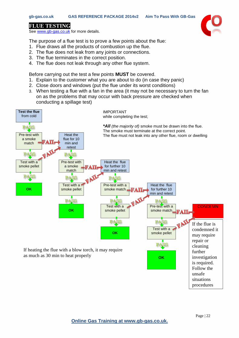
FLUE TESTING See www.gb-gas.co.uk for more details.
The purpose of a flue test is to prove a few points about the flue: 1. Flue draws all the products of combustion up the flue. 2. The flue does not leak from any joints or connections. 3. The flue terminates in the correct position. 4. The flue does not leak through any other flue system. Before carrying out the test a few points MUST be covered. 1. Explain to the customer what you are about to do (in case they panic) 2. Close doors and windows (put the flue under its worst conditions) 3. When testing a flue with a fan in the area (it may not be necessary to turn the fan
on as the problems that may occur with back pressure are checked when conducting a spillage test)
Test the flue
from cold
IMPORTANT while completing the test;
*All (the majority of) smoke must be drawn into the flue. The smoke must terminate at the correct point. The flue must not leak into any other flue, room or dwelling
Pre-test with a smoke match
Heat the flue for 10 min and retest
Test with a smoke pellet
Pre-test with a smoke match
Heat the flue for further 10
min and retest
OK
Test with a smoke pellet
Pre-test with a smoke match
Heat the flue for further 10
min and retest
OK
Test with a smoke pellet
Pre-test with a smoke match
CONDEMN
OK
Test with a smoke pellet
OK
If heating the flue with a blow torch, it may require
as much as 30 min to heat properly
If the flue is
condemned it
may require
repair or
cleaning
further
investigation
is required.
Follow the
unsafe
situations
procedures
Lengt
way

gb-gas.co.uk GAS REFERENCE PACKAGE 2014v2 Aim To Pass With GB-Gas
Page | 23
Hours of videos and quiz questions @ www.gb-gas.co.uk
SPILLAGE TESTING See www.gb-gas.co.uk for more details.
The purpose of a spillage test is to prove a few points about the appliance: 1. The appliance draws all the products of combustion into the flue. 2. The appliance and flue design are working correctly. 3. The appliance has no fumes entering the room 4. The appliance is safe to use Before carrying out the test a few points MUST be covered. 1. Explain to the customer what you are about to do (in case they panic) 2. Close doors and windows (put the flue under its worst conditions) 3. Turn the extractor fans on in the room and test 4. Turn extractor fans on in any other room in the house and leave the door
between the rooms open. And re test 5. When testing a flue with a fan in the area test with the fan on and with the fan off.
Heat the appliance for 5
minutes
IMPORTANT
while completing the test;
*All (the majority of)
smoke should be drawn into the appliance. The appliance must be left on at maximum setting.
Leave the appliance on
and place smoke match in the desired area
Heat the
appliance for further 10 min
Is all* the smoke drawn
into the appliance
Leave the appliance on
and place smoke match in the desired
area
CONDEMN
OK Is all* the smoke drawn
into the appliance
If the appliance fails then further investigation may be required
The appliance may be; 1. Over gassed. 2. Sooted up. 3. Blocked flue or flue ways. 4. Bad flue design. 5. Faulty appliance.
OK
o
Test

gb-gas.co.uk GAS REFERENCE PACKAGE 2014v2 Aim To Pass With GB-Gas
Page | 24
Online Gas Training at www.gb-gas.co.uk.
Spillage Testing for room sealed appliances See www.gb-gas.co.uk for more details.
• This to make sure the appliance is sealed form the room.
• Remove the outer case if it is not part of the seal.
• Visually inspect for any corrosion, distortion and problems with seals
• While the appliance is turned on
• Move a lighter or match around 1. All the case seals, 2. Viewing windows, 3. All Pipes and wires entering the
pressurised case 4. Around the flue seals
• If the lighter flame is distorted or blows out then this is a fail.
Positive Fan Pressure
Appliance list
Manufacturer and Model Manufacturer and Model Manufacturer and Model
Alde International (UK) Ltd Glynwed Domestic & Heating (cont.) Myson (Thorn) Olympic 38/50F
Alde 2927 Slimline Highlight P50 Myson (Thorn) Apollo Fanfare 15/30
Highlight P50A SC Myson (Thorn) Apollo Fanfare 30/50
Brassware Sales Ltd Highlight P50S Supaheat 50/15 with “A” control
Ferrolli 76FF Highlight P50SS Supaheat GC 50/15
Ferrolli 77FF Highlight P50S/A Netaheat MkI 10/16
Highlight P50S/A GLC Netaheat MkI 16/22 BF
Crosslee (JLB) (Pyrocraft) Highlight P50S/A SC Netaheat MkII 10/16 BF
AWB 23.09 WT Combi Highlight P50/A Netaheat MkII 16/22 BF
Highlight P70 Netaheat MkIIF 10-16 BF
Crosslee (Trisave Boilers Ltd) Highlight P70S Netaheat MkIIF 16-22 BF
Trisave Turbo T45 Highlight P70SS Netaheat Electronic 6/10
Trisave Turbo T60 Netaheat Electronic 10/16
Trisave Turbo 30 Halstead Heating & Engineering Ltd Netaheat Electronic 16/22
Trisave Turbo 22 Halstead 45F Netaheat Electronic 10/16e
Halstead 55F Netaheat Electronic 16/22e
Glow-worm Ltd Halstead 65F
Economy 30F Wickes 45F Stelrad Group Ltd
Economy 40F Wickes 65F Ideal Elan 2 40F
Economy 50F Barlo Balmoral 45F Ideal Elan 2 50F
Glow-worm Fuelsaver 35F Barlo Balmoral 55F Ideal Elan 2 60F
Glow-worm Fuelsaver 45F Barlo Balmoral 65F Ideal Elan 2 80F
Glow-worm Fuelsaver 55F Harvey Habridge Ltd Ideal Excel 30F
Glow-worm Fuelsaver 65F Impala MkII Ideal Excel 40F
Glow-worm Fuelsaver 80F Impala MkII Ridgeseal Ideal Excel 50F
Glow-worm Fuelsaver 100F Impala Ideal Excel 60F
Impala Super 2 (VF) Ideal Sprint 80F
Glynwed Domestic & Heating Ideal W2000 30F
AGA A50 Potterton Myson Ltd Ideal W2000 40F
AGA A50 A Netaheat Profile 30e Ideal W2000 50F
AGA A50 NG Netaheat Profile 40e Ideal W2000 60F
AGA A50 SS Netaheat Profile 50e
AGA A50 ANG Netaheat Profile 60e Worcester Bosch
AGA A60 Netaheat Profile 80e Heatslave 9.24 RSF
AGA A50 NG Netaheat Profile 100e Worcester 9.24 Electronic RSF
AGA A75 NG Myson (Thorn) Olympic 20/35F Worcester 9.24 Electronic RSF ‘S’
gb-gas.co.uk GAS REFERENCE PACKAGE 2014v2 Aim To Pass With GB-Gas
Page | 25
Hours of videos and quiz questions @ www.gb-gas.co.uk
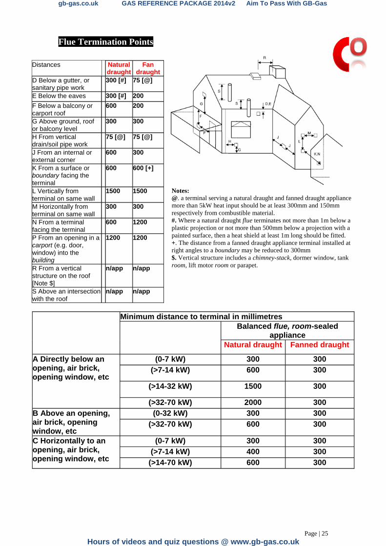
Flue Termination Points
Distances Natural draught
Fan draught
D Below a gutter, or sanitary pipe work
300 [#] 75 [@]
E Below the eaves 300 [#] 200
F Below a balcony or carport roof
600 200
G Above ground, roof or balcony level
300 300
H From vertical drain/soil pipe work
75 [@] 75 [@]
J From an internal or external corner
600 300
K From a surface or boundary facing the terminal
600 600 [+]
L Vertically from terminal on same wall
1500 1500
M Horizontally from terminal on same wall
300 300
N From a terminal facing the terminal
600 1200
P From an opening in a carport (e.g. door, window) into the building
1200 1200
R From a vertical structure on the roof [Note $]
n/app n/app
S Above an intersection with the roof
n/app n/app
Minimum distance to terminal in millimetres
Balanced flue, room-sealed appliance
Natural draught Fanned draught
A Directly below an opening, air brick, opening window, etc
(0-7 kW) 300 300
(>7-14 kW) 600 300
(>14-32 kW) 1500 300
(>32-70 kW) 2000 300
B Above an opening, air brick, opening window, etc
(0-32 kW) 300 300
(>32-70 kW) 600 300
C Horizontally to an opening, air brick, opening window, etc
(0-7 kW) 300 300
(>7-14 kW) 400 300
(>14-70 kW) 600 300
Notes: @. a terminal serving a natural draught and fanned draught appliance
more than 5kW heat input should be at least 300mm and 150mm
respectively from combustible material.
#. Where a natural draught flue terminates not more than 1m below a
plastic projection or not more than 500mm below a projection with a
painted surface, then a heat shield at least 1m long should be fitted.
+. The distance from a fanned draught appliance terminal installed at
right angles to a boundary may be reduced to 300mm
$. Vertical structure includes a chimney-stack, dormer window, tank
room, lift motor room or parapet.
gb-gas.co.uk GAS REFERENCE PACKAGE 2014v2 Aim To Pass With GB-Gas
Page | 26
Online Gas Training at www.gb-gas.co.uk.
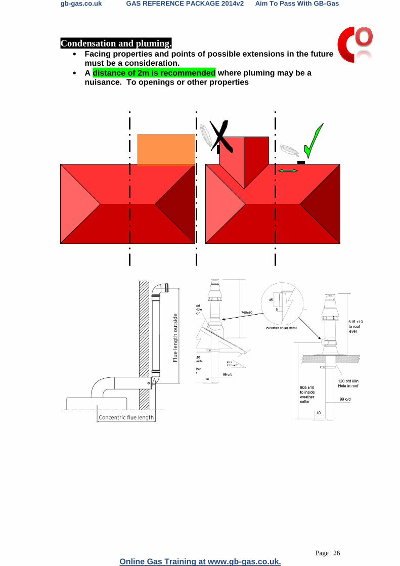
Condensation and pluming. • Facing properties and points of possible extensions in the future
must be a consideration.
• A distance of 2m is recommended where pluming may be a nuisance. To openings or other properties
gb-gas.co.uk GAS REFERENCE PACKAGE 2014v2 Aim To Pass With GB-Gas
Page | 27
Hours of videos and quiz questions @ www.gb-gas.co.uk
Simple gas faultfinding on appliances Typical Gas Component Faults on Central Heating Boilers and
Circulators
Unsatisfactory Ignition Of Burners / Flame Supervision Devices; Flames not igniting, Explosive ignition due to a range of possible faults; Pilot flame to small Pilot flame not in correct position Faulty FSD To much gas at the main burner Not enough gas at the main burner
Unstable Flame Picture
Incorrect flame due to a range of possible faults Over gassed (Long flames with possible yellow tips) Lack of oxygen (Yellow flames) Cracked burners
Blocked burners (Choked with soot)
Signs Of Spillage
Sooting in or around the appliance or appliance seals Pattern staining from the draught diverter
Inoperative Thermostats Inoperative operating thermostats giving temperature problems (to hot or to cold) If operating thermostat fails on a system boiler. The high limit stat will lock the boiler out (requires to be manually reset) If high limit stat also fails steaming hot water will discharge from the pressure relief valve. This will drop the pressure from the boiler. (requires to be manually reset)
Inoperative Air Pressure Switch
Symptoms on a fan flued boiler would be The boiler fan starts up but the ignition sequence does not start ( The fan pressure switch starts the ignition sequence)
Inoperative Multifunction Control Valve
a multifunction control valve contains three main components a FSD, a Solenoid a Regulator all three components must work correctly.
gb-gas.co.uk GAS REFERENCE PACKAGE 2014v2 Aim To Pass With GB-Gas
Page | 28
Online Gas Training at www.gb-gas.co.uk.
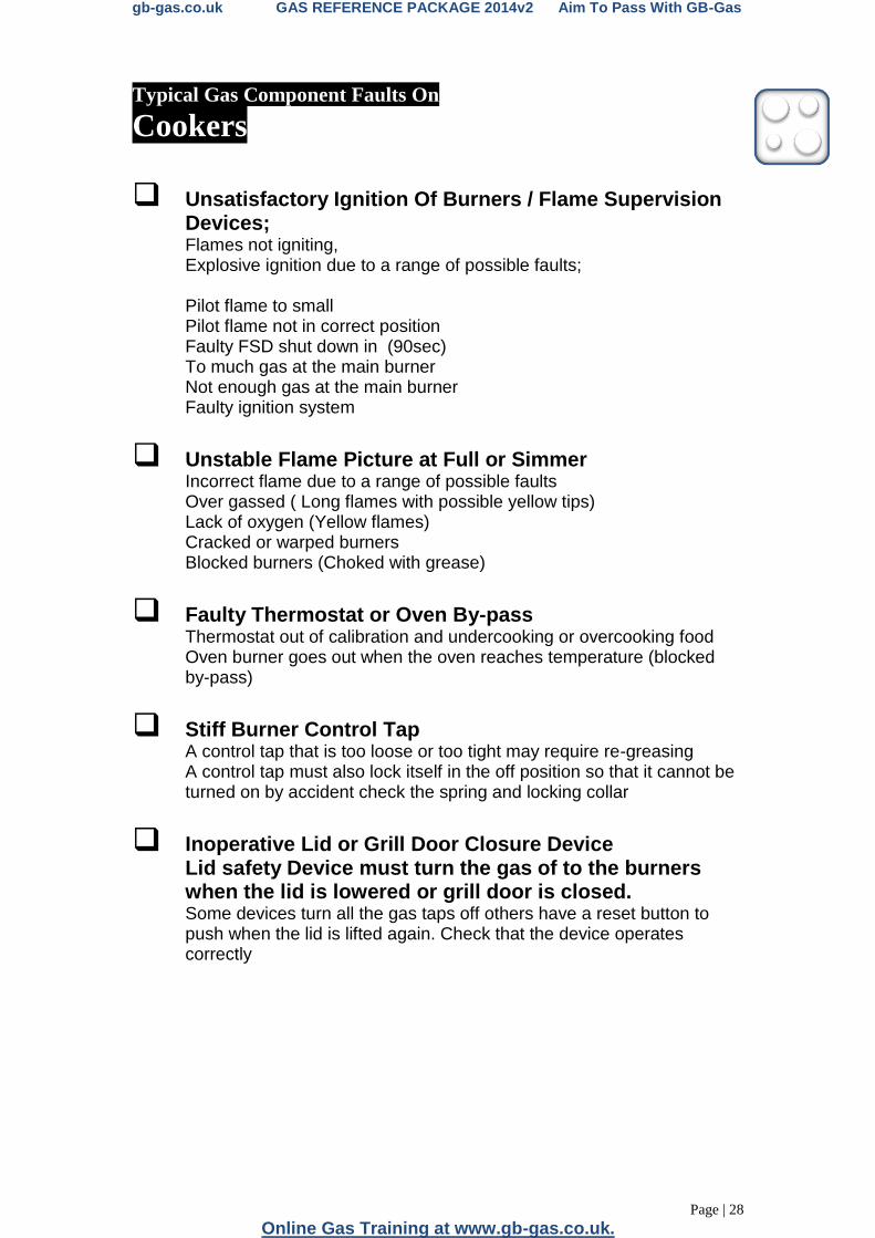
Typical Gas Component Faults On
Cookers
Unsatisfactory Ignition Of Burners / Flame Supervision Devices; Flames not igniting, Explosive ignition due to a range of possible faults; Pilot flame to small Pilot flame not in correct position Faulty FSD shut down in (90sec) To much gas at the main burner Not enough gas at the main burner
Faulty ignition system
Unstable Flame Picture at Full or Simmer
Incorrect flame due to a range of possible faults Over gassed ( Long flames with possible yellow tips) Lack of oxygen (Yellow flames) Cracked or warped burners
Blocked burners (Choked with grease)
Faulty Thermostat or Oven By-pass
Thermostat out of calibration and undercooking or overcooking food Oven burner goes out when the oven reaches temperature (blocked by-pass)
Stiff Burner Control Tap A control tap that is too loose or too tight may require re-greasing A control tap must also lock itself in the off position so that it cannot be turned on by accident check the spring and locking collar
Inoperative Lid or Grill Door Closure Device
Lid safety Device must turn the gas of to the burners when the lid is lowered or grill door is closed. Some devices turn all the gas taps off others have a reset button to push when the lid is lifted again. Check that the device operates correctly

gb-gas.co.uk GAS REFERENCE PACKAGE 2014v2 Aim To Pass With GB-Gas
Page | 29
Hours of videos and quiz questions @ www.gb-gas.co.uk
Typical Gas Component Faults On
Space Heating (gas fires)
Unsatisfactory Ignition Of Burners / Flame Supervision Devices; Flames not igniting, Explosive ignition due to a range of possible faults; Pilot flame to small Pilot flame not in correct position Faulty FSD To much gas at the main burner Not enough gas at the main burner
Unstable Flame Picture
Incorrect flame due to a range of possible faults Over gassed ( Long flames with possible yellow tips) Lack of oxygen (Yellow flames) Cracked burners
Blocked burners (Choked with soot)
Signs Of Spillage
Sooting in or around the appliance or appliance seals Pattern staining from the draught diverter
Incorrect position of fuel on the fuel bed If the wrong size of radiant or the incorrect amount of coals are used on a gas fire the result could be Flame impingement Incomplete combustion In either case the burner will not operate correctly, with the appliance becoming sooted
Inoperable or Stiff control tap Check that the gas tap is easy to work and that it controls the full range of settings on the appliance
Inoperative Air Pressure Switch
Symptoms on a fan gas fire would be The boiler fan starts up but the ignition sequence does not start (The fan pressure switch starts the ignition sequence)

gb-gas.co.uk GAS REFERENCE PACKAGE 2014v2 Aim To Pass With GB-Gas
Page | 30
Online Gas Training at www.gb-gas.co.uk.
Typical Gas Component Faults On
Warm Air Units. Unsatisfactory Ignition Of Burners / Flame Supervision
Devices; Flames not igniting, Explosive ignition due to a range of possible faults; Pilot flame to small Pilot flame not in correct position Faulty FSD To much gas at the main burner Not enough gas at the main burner
Unstable Flame Picture
Incorrect flame due to a range of possible faults Over gassed ( Long flames with possible yellow tips) Lack of oxygen (Yellow flames) Cracked burners CRACKED HEAT EXCHANGER/
Blocked burners (Choked with soot) NO RETURN AIR DUCT
Signs Of Spillage
Sooting in or around the appliance or appliance seals Pattern staining from the draught diverter
Inoperative Thermostats Warm air units have a low temperature thermostat this lets the burner turn on and heat, the heat exchanger before the fan unit turns on. and a high temperature thermostat this turns the burner off when the heat exchanger gets too hot, but lets the fan keep running. If it does not operate in this sequence then the thermostat(s) may be faulty.
Faulty Heat Exchanger
Symptoms of a cracked heat exchanger would be The flame picture is very poor (flames blown side ways) Products of combustion entering all warm air ducting Pilot flame blowing out. Fail spillage test at burner.
Inoperative Multifunction Control Valve
a multifunction control valve contains three main components a FSD, a Solenoid a Regulator all three components must work correctly.
gb-gas.co.uk GAS REFERENCE PACKAGE 2014v2 Aim To Pass With GB-Gas
Page | 31
Hours of videos and quiz questions @ www.gb-gas.co.uk
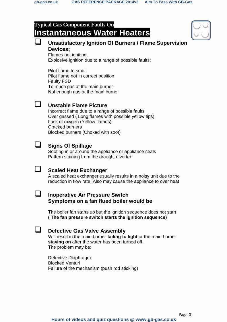
Typical Gas Component Faults On
Instantaneous Water Heaters
Unsatisfactory Ignition Of Burners / Flame Supervision Devices; Flames not igniting, Explosive ignition due to a range of possible faults; Pilot flame to small Pilot flame not in correct position Faulty FSD To much gas at the main burner Not enough gas at the main burner
Unstable Flame Picture
Incorrect flame due to a range of possible faults Over gassed ( Long flames with possible yellow tips) Lack of oxygen (Yellow flames) Cracked burners
Blocked burners (Choked with soot)
Signs Of Spillage
Sooting in or around the appliance or appliance seals Pattern staining from the draught diverter
Scaled Heat Exchanger A scaled heat exchanger usually results in a noisy unit due to the reduction in flow rate. Also may cause the appliance to over heat
Inoperative Air Pressure Switch
Symptoms on a fan flued boiler would be The boiler fan starts up but the ignition sequence does not start ( The fan pressure switch starts the ignition sequence)
Defective Gas Valve Assembly
Will result in the main burner failing to light or the main burner staying on after the water has been turned off. The problem may be: Defective Diaphragm Blocked Venturi Failure of the mechanism (push rod sticking)
gb-gas.co.uk GAS REFERENCE PACKAGE 2014v2 Aim To Pass With GB-Gas
Page | 32
Online Gas Training at www.gb-gas.co.uk.
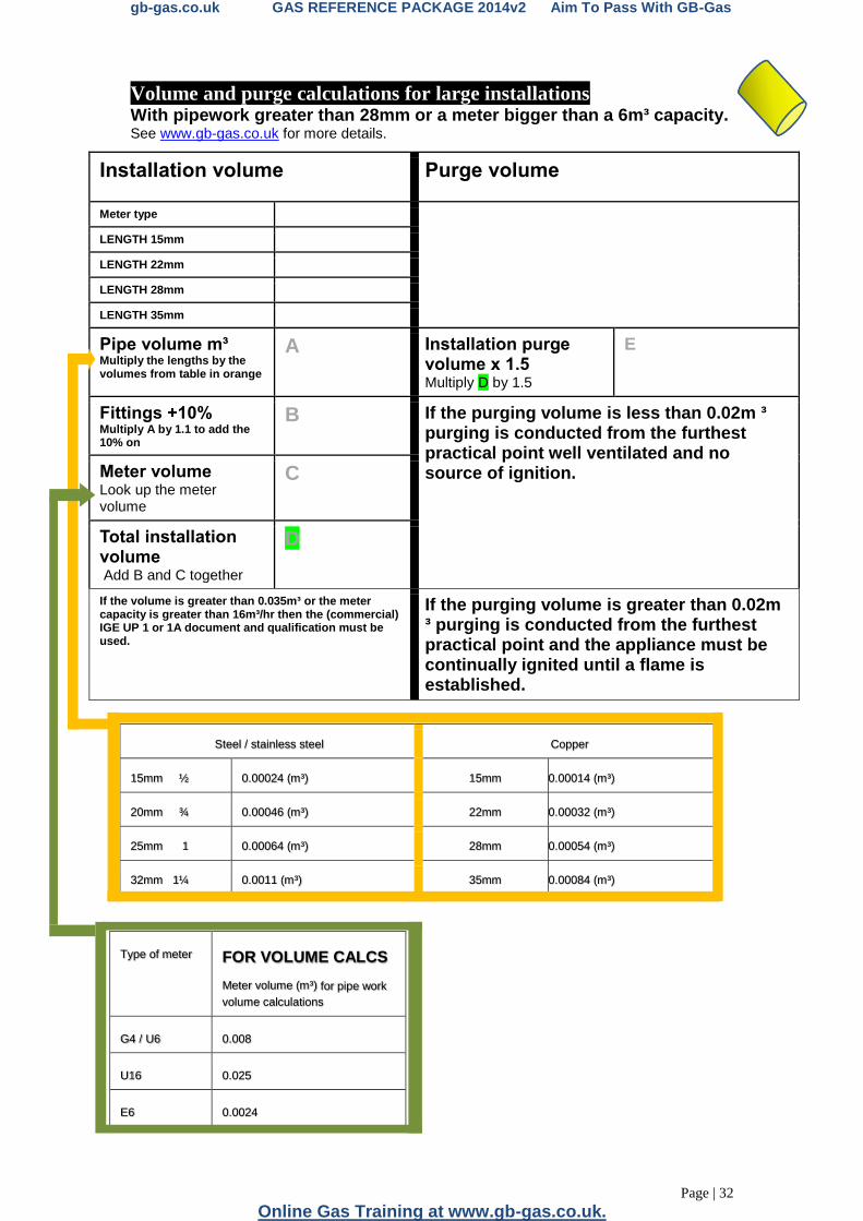
Volume and purge calculations for large installations With pipework greater than 28mm or a meter bigger than a 6m³ capacity. See www.gb-gas.co.uk for more details.
Installation volume Purge volume
Meter type LENGTH 15mm
LENGTH 22mm
LENGTH 28mm
LENGTH 35mm
Pipe volume m³ Multiply the lengths by the volumes from table in orange
A Installation purge volume x 1.5 Multiply D by 1.5
E
Fittings +10% Multiply A by 1.1 to add the 10% on
B If the purging volume is less than 0.02m ³ purging is conducted from the furthest practical point well ventilated and no source of ignition.
Meter volume Look up the meter volume
C
Total installation volume Add B and C together
D
If the volume is greater than 0.035m³ or the meter capacity is greater than 16m³/hr then the (commercial) IGE UP 1 or 1A document and qualification must be used.
If the purging volume is greater than 0.02m ³ purging is conducted from the furthest practical point and the appliance must be continually ignited until a flame is established.
Steel / stainless steel Copper
15mm ½ 0.00024 (m³) 15mm 0.00014 (m³)
20mm ¾ 0.00046 (m³) 22mm 0.00032 (m³)
25mm 1 0.00064 (m³) 28mm 0.00054 (m³)
32mm 1¼ 0.0011 (m³) 35mm 0.00084 (m³)
Type of meter FOR VOLUME CALCS
Meter volume (m³) for pipe work
volume calculations
G4 / U6 0.008
U16 0.025
E6 0.0024
gb-gas.co.uk GAS REFERENCE PACKAGE 2014v2 Aim To Pass With GB-Gas
Page | 33
Hours of videos and quiz questions @ www.gb-gas.co.uk
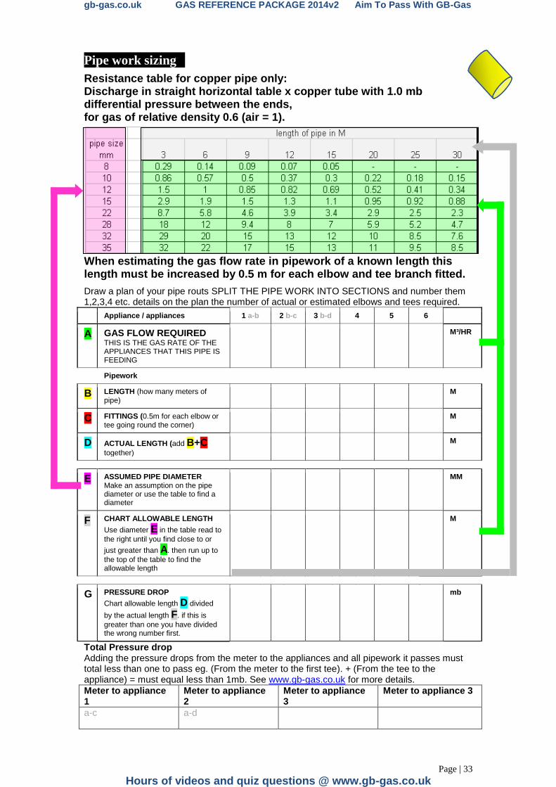
Pipe work sizing
Resistance table for copper pipe only: Discharge in straight horizontal table x copper tube with 1.0 mb differential pressure between the ends, for gas of relative density 0.6 (air = 1).
When estimating the gas flow rate in pipework of a known length this length must be increased by 0.5 m for each elbow and tee branch fitted.
Draw a plan of your pipe routs SPLIT THE PIPE WORK INTO SECTIONS and number them 1,2,3,4 etc. details on the plan the number of actual or estimated elbows and tees required.
Appliance / appliances 1 a-b 2 b-c 3 b-d 4 5 6
A GAS FLOW REQUIRED THIS IS THE GAS RATE OF THE APPLIANCES THAT THIS PIPE IS FEEDING
M³/HR
Pipework
B LENGTH (how many meters of pipe)
M
C FITTINGS (0.5m for each elbow or tee going round the corner)
M
D ACTUAL LENGTH (add B+C together)
M
E ASSUMED PIPE DIAMETER Make an assumption on the pipe diameter or use the table to find a diameter
MM
F CHART ALLOWABLE LENGTH
Use diameter E in the table read to
the right until you find close to or
just greater than A. then run up to
the top of the table to find the allowable length
M
G PRESSURE DROP
Chart allowable length D divided
by the actual length F. if this is
greater than one you have divided the wrong number first.
mb
Total Pressure drop Adding the pressure drops from the meter to the appliances and all pipework it passes must total less than one to pass eg. (From the meter to the first tee). + (From the tee to the appliance) = must equal less than 1mb. See www.gb-gas.co.uk for more details.
Meter to appliance 1
Meter to appliance 2
Meter to appliance 3
Meter to appliance 3
a-c
a-d

gb-gas.co.uk GAS REFERENCE PACKAGE 2014v2 Aim To Pass With GB-Gas
Page | 34
Online Gas Training at www.gb-gas.co.uk.
Notes: