onlite - voltimum sverige · pdf fileonlite contents 5 design by studio matteo thun 6–7...
TRANSCRIPT


ONLITEEmergency lighting
www.zumtobelstaff.com/onlite
Dokument 2 17.03.2004 16:37 Uhr Seite 2
ONLITEEmergency lighting
Dokument 2 17.03.2004 16:37 Uhr Seite 3

Everything is running as smoothly
as clockwork. Everyone knows
precisely what they have to do
and people are working as a team.
Light works with you. It is general
lighting. It ensures a sense of
well-being and provides ergonom-
ically correct and economically
affordable light.
It’s great when everything works.
Dokument 2 17.03.2004 16:37 Uhr Seite 4

Power failure? Danger?
An emergency? Now’s the time
for safety, this is when everything
boils down to one question: do
we have an integrated lighting
solution? Is our emergency lighting
system integrated into our general
lighting system and therefore
really dependable? Does it offer
automatic monitoring and hence
require less effort? Do we have a
system solution which can be
networked in order to cut costs?
People who use ONLITE can
breathe a sigh of relief.
O N L I T E D E S I G N 3


5O N L I T E C O N T E N T S
Design by Studio Matteo Thun 6–7
The ONLITE concept 8–9
The 4-pillar model 10–11
ONLITE look, ONLITE local, ONLITE central, ONLITE service
ONLITE look artsign 12–15
This design wonder is the smallest escape sign
luminaire in the world: a perfect blend of design
and technology.
comsign 16–19
Materials: a light and transparent appearance,
but at the same time hard-wearing.
ecosign 20–23
The all-rounder which incorporates a whole range
of practical qualities. The ecosign family includes
an emergency luminaire of identical construction.
ONLITE local integrated lighting solution 24–25
ONLITE emergency lighting systems are guaranteed
comprehensive lighting solutions: compatible, network-
capable and integrated into the general lighting system
ONLITE local The revolutionary separate battery power supply 26–29
local check and the SB 128 controller 30–31
local check systems and topologies 32–33
ONLITE central integrated lighting solution 34–35
ONLITE section central Inspiring features 36–37
Testing and maintanance 38–39
Modular construction, maximum flexibility 40–41
Systems and topologies 42–43
Systems and topologies using LUXMATE 44–45
ONLITE service 46–47
The complete service package starting from dependable design
work right through to customised training
Summary of emergency power sources 48
ONLITE look artsign 49–50
comsign 51–53
ecosign 54–58
ONLITE local supply and monitoring modules 59–60
Emergency Sets 61–63
ONLITE central section central 360 64
section central 720/1080/1440 65
Power supply and monitoring modules 66–67

“Our Studio promotes extensive interaction
between architecture and industrial design.
In doing so we prefer interdisciplinary
teamwork over individual expressiveness,
consumers’ demands over formal conven-
tions, clarity over complexity, functionality
over imagery and prolific inventiveness
over a consumerist mentality.”
Created byMatteo Thun with Lutz Büsing
ONLITE products are based on the principle
of non-design: formal reduction in order
to put the architecture to the fore, and
optimised use of materials for maximum
functionality at minimum product size.
Matteo Thun introduces the “second
generation” of modern architects: stylistic-
ally hard to pin down and suspicious of
established thought patterns and para-
digms. Matteo Thun searches for strategies
for his customers in order to multiply
identities rather than concentrate them.
People in every sector are talking about
“design” but they always mean the design
of systems – design has become a modern
metaphor: everybody is talking about
design, everybody is thinking about design
– but nobody relates it to singular objects
any more. This is a holistic thought process
which is applied in many areas.
O N L I T E M A T T E O T H U ND E S I G N
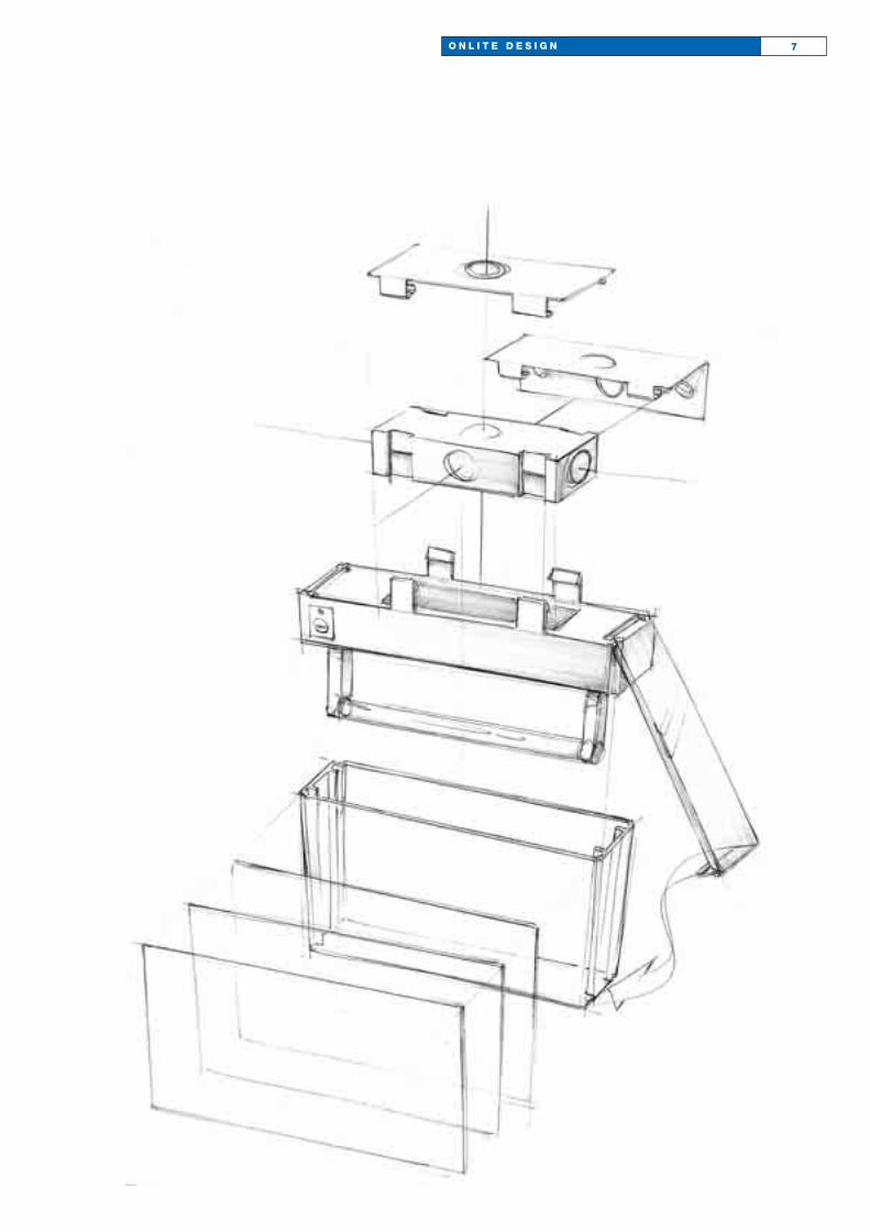
7O N L I T E D E S I G N

ONLITE functions and adapts dependably

9O N L I T E C O N C E P T
Closes gaps and opens up paths
ONLITE is the safety part of a
comprehensive lighting solution:
secured system guarantee,
guaranteed innovation, tried and
tested integration. All this makes
ONLITE a highly compatible safety
tool which effortlessly copes with
everyday life in buildings.
Adapts and watches out
ONLITE achieves the delicate
balancing act between aesthetics
and functionality by taking a
straightforward approach.
ONLITE can adapt to various
dimensions like a chameleon
adapts to its surroundings.
Is simple and remains simple
The systematic thinking behind
ONLITE guarantees everyone
involved the security they need.
From the logical structure of the
product ranges right through
to a sustained service and
support plan.
ONLITE is compatible with other building services. Integration
and networking with bus systems. Multi-functionality with cabling.
ONLITE is perfectly qualified for every task. The right solution for
every application. The quality response to every question.
Consistent brand quality, all-round safety.
ONLITE takes over the management of complex safety systems.
Fully functioning interfaces with all building services.
Competence that reflects thinking outside the box.
ONLITE fits in and pleases the eye. Its design brings fresh
aesthetic responses to old tasks.
ONLITE fulfils all expectations. Everything is possible,
thanks to a broad product range for every application.
ONLITE has an architectural quality. Unobtrusively designed
non-design products for architects and users.
ONLITE has a clear structure with the user-friendly
easy-to-understand 4-pillar model.
ONLITE aims to be the best and achieves satisfaction.
Dependable, reduced design effort. Fast and simple installation.
A reliable partnership on which building owners or general
contractors can depend.
ONLITE is easy to grasp, operate and understand.
Clear application recommendations bring faster results.
The uniform CLIX mechanism is a hit.
Easy to link to Building Management Services (BMS), easy to
interrogate and easy to evaluate to make everyday life simpler.

The ONLITE Family. The 4-pillar model –a certain logic
Product-
type
Product
Product-
name
Luminaires Monitoring/controllingusing separate battery systems
Supplying/monitoringwith central systems
Services
ONLITE look ONLITE local ONLITE central ONLITE service
ONLITE lookartsign
ONLITE lookcomsign
ONLITE lookecosign
ecosignlocal solo DS 1h(maintained mode)
comsignlocal check DS 1h(maintained mode)
artsigncentral EW-LO
ecosignRZ-2U
ONLITE local checkcontroller
ONLITE local checkmoduls
ONLITE local checksoftware
SB 128 local checkcontroller
SB 64 local checkextender
SB GSM local check
ONLITE centralsection
ONLITE centralmoduls
ONLITE centralsoftware
section central360 1h05/2
section central1080 1h05/5
PLC central DALIinterface
section central printer
section central EPDphase monitoring
ONLITE serviceplan
ONLITE serviceoperation
ONLITE servicecare
ONLITE serviceinform
plan concept
operation function
inform trainingsolution
11O N L I T E 4 - P I L L A R M O D E L
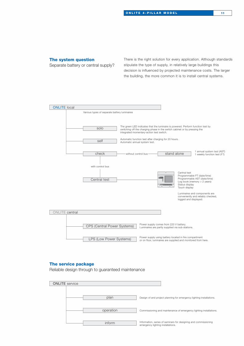
The system questionSeparate battery or central supply?
solo
self
check
with control bus
Central test
stand alone
ONLITE localVarious types of separate battery luminaires
The green LED indicates that the luminaire is powered. Perform function test by switching off the charging phase in the switch cabinet or by pressing the integrated momentary-action test switch.
Automatic function test after charging for 20 hours.Automatic annual system test.
1 annual system test (AST)1 weekly function test (FT)
Central testProgrammable FT (date/time)Programmable AST (date/time)Log book (memory > 2 years)Status displayTouch display
Luminaires and components are conveniently and reliably checked, logged and displayed.
CPS (Central Power Systems)
LPS (Low Power Systems)
ONLITE central
Power supply comes from 220 V battery.Luminaires are partly supplied via sub-stations.
Power supply using battery located in fire compartment or on floor, luminaires are supplied and monitored from here.
without control bus
plan
operation
ONLITE service
Design of and project planning for emergency lighting installations.
Commissioning and maintenance of emergency lighting installations.
inform Information, series of seminars for designing and commissioning emergency lighting installations.
The service packageReliable design through to guaranteed maintenance
There is the right solution for every application. Although standards
stipulate the type of supply, in relatively large buildings this
decision is influenced by projected maintenance costs. The larger
the building, the more common it is to install central systems.


ONLITE lookARTSIGN A design sensation in its own right
This little design sensation is innovation
through and through. Something so small
has never before been seen, such freedom
from maintenance (thanks to the LED tech-
nology used) has never been known before.
ARTSIGN is smaller than a postcard and
almost as slim; it is clearly visible, whilst
remaining invisible! Architects in particular
will like ARTSIGN. The pictogram measures
precisely 75 x 150 mm and can be recessed
flush into the wall.
It will function many years without main-
tenance – special LEDs are responsible
for this long service life and convenience.
The white light is generated by COB
(Chip On Board) LEDs in the case of the
high-output model.
O N L I T E L O O K A R T S I G N 13
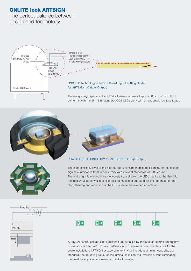
Standard LED 5 mm
TRIDONICpower LED 2 mm
Chip padBond wire (Al, Au)
LP-pad
Bare chip (DIE)Thermal bonding agentSealing compoundPrinted board (substrate)
COB LED technology (Chip On Board Light Emitting Diode)
for ARTSIGN LO (Low Output)
The escape sign symbol is backlit at a luminance level of approx. 80 cd/m2, and thus
conforms with the EN 1838 standard. COB LEDs work with an extremely low loss factor.
POWER LED TECHNOLOGY for ARTSIGN HO (High Output)
The high efficiency level of the high-output luminaire enables backlighting of the escape
sign at a luminance level in conformity with relevant standards of 200 cd/m2.
The white light is emitted homogeneously from all over the LED; thanks to the flip-chip
technology used, in which all electrical connections are fitted on the underside of the
chip, shading and reduction of the LED surface are avoided completely.
ARTSIGN central escape sign luminaires are supplied by the Section central emergency
power source fitted with 10-year batteries which require minimal maintenance for the
entire installation. ARTSIGN escape sign luminaires include a dimming capability as
standard, the actuating value for the luminaires is sent via Powerline, thus eliminating
the need for any special cinema or theatre luminaire.
EPS 360
Powerline
ONLITE look ARTSIGNThe perfect balance between design and technology
15O N L I T E L O O K A R T S I G N
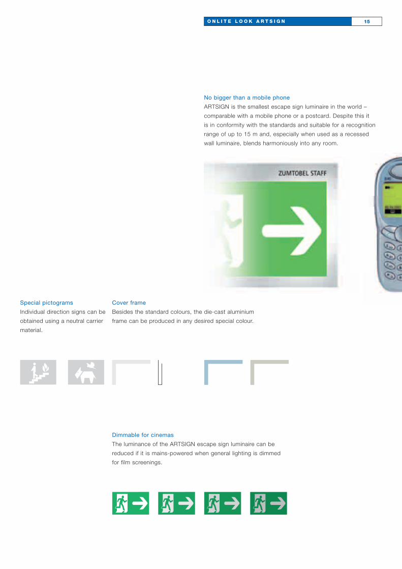
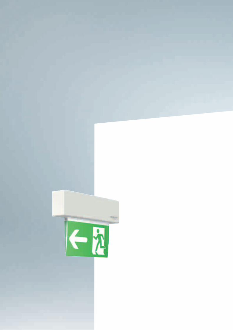
No bigger than a mobile phone
ARTSIGN is the smallest escape sign luminaire in the world –
comparable with a mobile phone or a postcard. Despite this it
is in conformity with the standards and suitable for a recognition
range of up to 15 m and, especially when used as a recessed
wall luminaire, blends harmoniously into any room.
Dimmable for cinemas
The luminance of the ARTSIGN escape sign luminaire can be
reduced if it is mains-powered when general lighting is dimmed
for film screenings.
Cover frame
Besides the standard colours, the die-cast aluminium
frame can be produced in any desired special colour.
Special pictograms
Individual direction signs can be
obtained using a neutral carrier
material.
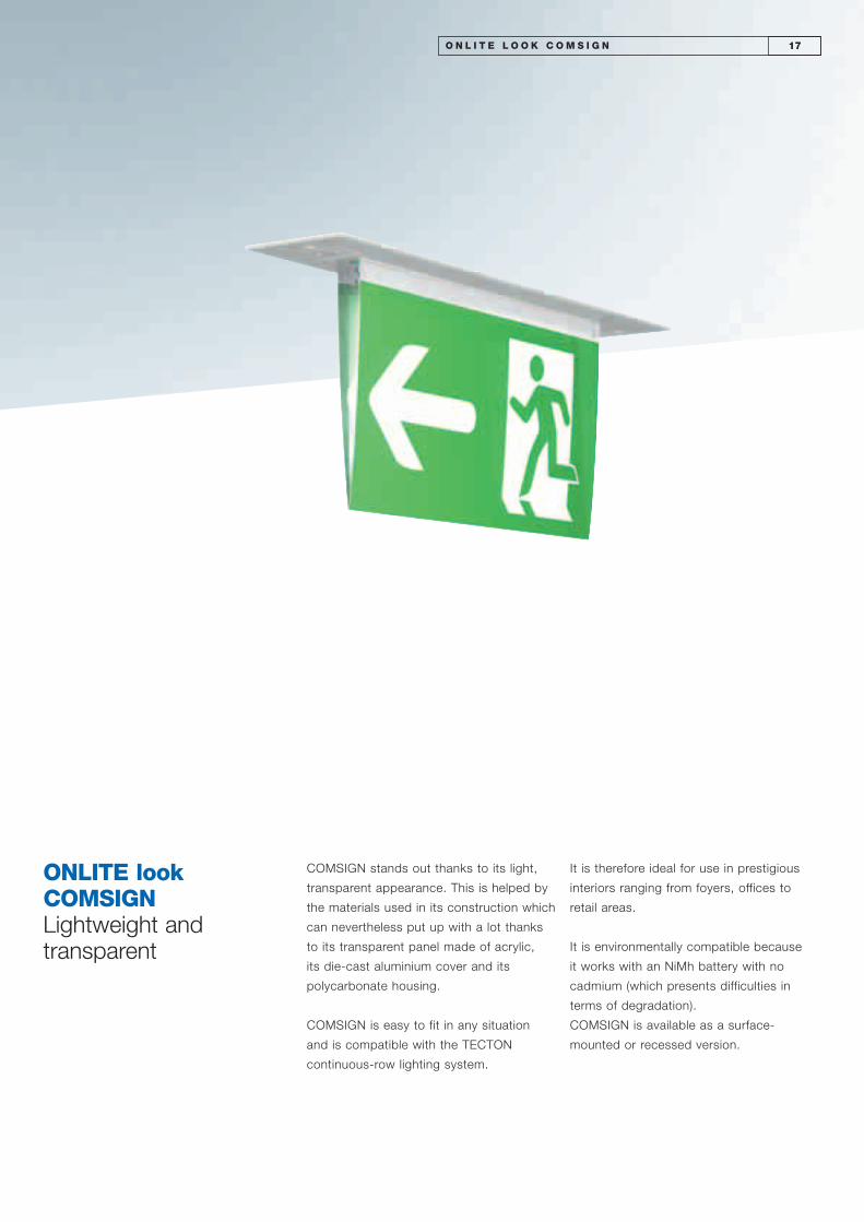
ONLITE lookCOMSIGN Lightweight and transparent
COMSIGN stands out thanks to its light,
transparent appearance. This is helped by
the materials used in its construction which
can nevertheless put up with a lot thanks
to its transparent panel made of acrylic,
its die-cast aluminium cover and its
polycarbonate housing.
COMSIGN is easy to fit in any situation
and is compatible with the TECTON
continuous-row lighting system.
It is therefore ideal for use in prestigious
interiors ranging from foyers, offices to
retail areas.
It is environmentally compatible because
it works with an NiMh battery with no
cadmium (which presents difficulties in
terms of degradation).
COMSIGN is available as a surface-
mounted or recessed version.
O N L I T E L O O K C O M S I G N 17
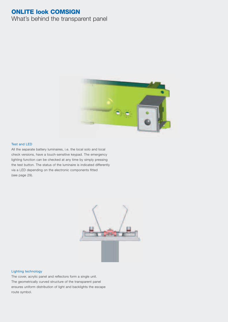
ONLITE look COMSIGN What’s behind the transparent panel
Test and LED
All the separate battery luminaires, i.e. the local solo and local
check versions, have a touch-sensitive keypad. The emergency
lighting function can be checked at any time by simply pressing
the test button. The status of the luminaire is indicated differently
via a LED depending on the electronic components fitted
(see page 29).
Lighting technology
The cover, acrylic panel and reflectors form a single unit.
The geometrically curved structure of the transparent panel
ensures uniform distribution of light and backlights the escape
route symbol.

19O N L I T E L O O K C O M S I G N
Surface mounting
Surface mounting is obtained
using the mounting plate. Once
the two screws are in place, the
luminaire can be snapped into
position without any tools using
the CLIX mechanism. The basic
housing is supplied together
with the mounting plate.
Through-wiring
All luminaires are fitted with
a terminal block for through-
wiring. 2 x 5 x 2.5 mm2
conductors can be looped
through.
Recognition range
The escape route symbol is excellently and uniformly backlit to
ensure a luminaire recognition range of 26 m in accordance with
EN 1838. All products which operate in maintained mode also
have a luminance of 200 cd/m2 if they are mains-powered,
thus being in conformity with standards DIN 4844 and EN 1838.
Glow wire test
(according to EN 60 598-2-22)
Compliance is achieved by
using a polycarbonate material.
This enables the luminaire to
withstand glow wire testing
at 850 °C.
Addressing mode
– Auto addressing
– Mechanical set-up using
rotary switch
– GSM addressing
(using optional module)
Protection type
The construction of the
luminaire provides protection
equivalent to at least IP 20.
TECTON
The pre-wired TECTON-ONLITE adapter can be snapped onto
the track without the use of any tool before fitting the COMSIGN
luminaire. The TECTON adapter can be rotated through up to
90° and then locked in order to ensure perfect alignment with
the direction of escape.
Suspension systems
Optimum flexibility in terms of length is achieved by suspension
systems which can be altered on site:
– Double cord
– 40 x 40 mm aluminium tube which can be cut to length on site
Light sources
Each luminaire is shipped with a T16 fluorescent lamp rated at
410 lm. The patented filament heating system in emergency mode
ensures a long service life and also avoids the lamp being started
when cold.
10
44
26 m
IP 20
F D
Can be installed on normally
flammable surfaces (90 °C).
DF
Surface temperature of
luminaire is limited to 150 °C
(referred to vertical parts of
luminaire)

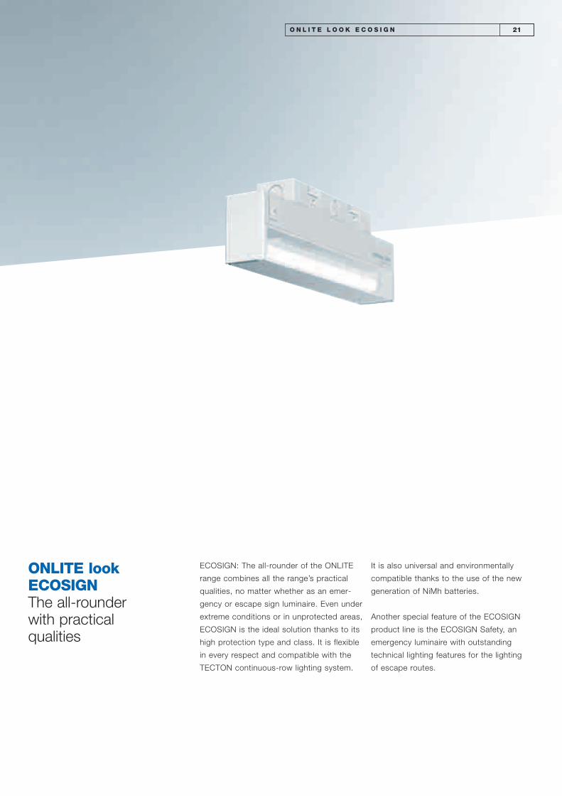
ONLITE lookECOSIGN The all-rounder with practical qualities
ECOSIGN: The all-rounder of the ONLITE
range combines all the range’s practical
qualities, no matter whether as an emer-
gency or escape sign luminaire. Even under
extreme conditions or in unprotected areas,
ECOSIGN is the ideal solution thanks to its
high protection type and class. It is flexible
in every respect and compatible with the
TECTON continuous-row lighting system.
It is also universal and environmentally
compatible thanks to the use of the new
generation of NiMh batteries.
Another special feature of the ECOSIGN
product line is the ECOSIGN Safety, an
emergency luminaire with outstanding
technical lighting features for the lighting
of escape routes.
O N L I T E L O O K E C O S I G N 21
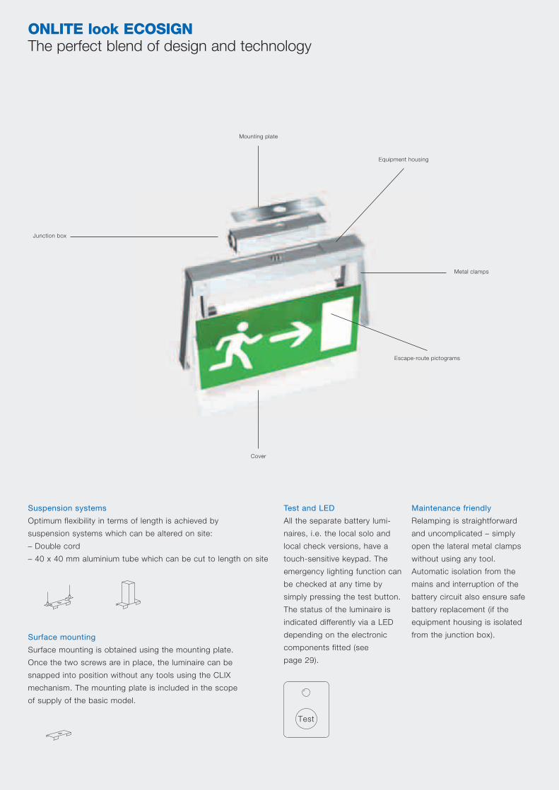
ONLITE look ECOSIGN The perfect blend of design and technology
Mounting plate
Metal clamps
Equipment housing
Escape-route pictograms
Cover
Junction box
Surface mounting
Surface mounting is obtained using the mounting plate.
Once the two screws are in place, the luminaire can be
snapped into position without any tools using the CLIX
mechanism. The mounting plate is included in the scope
of supply of the basic model.
Maintenance friendly
Relamping is straightforward
and uncomplicated – simply
open the lateral metal clamps
without using any tool.
Automatic isolation from the
mains and interruption of the
battery circuit also ensure safe
battery replacement (if the
equipment housing is isolated
from the junction box).
Suspension systems
Optimum flexibility in terms of length is achieved by
suspension systems which can be altered on site:
– Double cord
– 40 x 40 mm aluminium tube which can be cut to length on site
Test and LED
All the separate battery lumi-
naires, i.e. the local solo and
local check versions, have a
touch-sensitive keypad. The
emergency lighting function can
be checked at any time by
simply pressing the test button.
The status of the luminaire is
indicated differently via a LED
depending on the electronic
components fitted (see
page 29).
Test

23O N L I T E L O O K E C O S I G N
Through-wiring
All luminaires are fitted with
a terminal block for through-
wiring. 2 x 5 x 2.5 mm2
conductors can be looped
through.
Recognition range
The escape route symbol is excellently and uniformly backlit to
ensure a luminaire recognition range of 32 m in accordance with
EN 1838. All products which operate in maintained mode also
have a luminance of 200 cd/m2 if they are mains-powered,
thus being in conformity with standards DIN 4844 and EN 1838.
Escape-route lighting
Additional lighting of the escape route is obtained thanks to the
light exit surface underneath, external prisms provide optimum
direction of light.
Glow wire test
(according to EN 60 598-2-22)
Compliance is achieved by using a polycarbonate material. This
enables the luminaire to withstand glow wire testing at 850 °C.
Protection class II
Where the luminaire has a cable,
all products in the ECOSIGN
range meet protecion class II
requirements.
Exception: TECTON luminaire
has earthed metal parts and is
therefore protection class I.
Addressing mode
– Auto addressing
– Mechanical set-up
using rotary switch
– GSM addressing
(using optional module)
Protection type
Where luminaire has a feeder
cable, all products in the
ECOSIGN range meet protec-
tion type IP 65 requirements.
Exception: TECTON luminaire
where protection type is IP 40.
TECTON
The pre-wired TECTON-ONLITE adapter can be snapped onto
the track without the use of any tool before fitting the ECOSIGN
luminaire. The TECTON adapter can be rotated through up to
90° and then locked in order to ensure perfect alignment with
the direction of escape.
Light sources
Each luminaire is shipped with
a T16 fluorescent lamp rated at
410 lm. The patented filament
heating system in emergency
mode ensures a long service
life and also avoids the lamp
being started when cold.
10
44 32 m
IP 65
F D
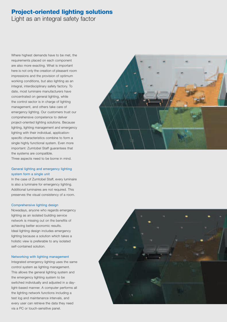
Project-oriented lighting solutionsLight as an integral safety factor
Where highest demands have to be met, the
requirements placed on each component
are also more exacting. What is important
here is not only the creation of pleasant room
impressions and the provision of optimum
working conditions, but also lighting as an
integral, interdisciplinary safety factory. To
date, most luminaire manufacturers have
concentrated on general lighting, while
the control sector is in charge of lighting
management, and others take care of
emergency lighting. Our customers trust our
comprehensive competence to deliver
project-oriented lighting solutions. Because
lighting, lighting management and emergency
lighting with their individual, application-
specific characteristics combine to form a
single highly functional system. Even more
important: Zumtobel Staff guarantees that
the systems are compatible.
Three aspects need to be borne in mind.
General lighting and emergency lighting
system form a single unit
In the case of Zumtobel Staff, every luminaire
is also a luminaire for emergency lighting.
Additional luminaires are not required. This
preserves the visual consistency of a room.
Comprehensive lighting design
Nowadays, anyone who regards emergency
lighting as an isolated building service
network is missing out on the benefits of
achieving better economic results.
Ideal lighting design includes emergency
lighting because a solution which takes a
holistic view is preferable to any isolated
self-contained solution.
Networking with lighting management
Integrated emergency lighting uses the same
control system as lighting management.
This allows the general lighting system and
the emergency lighting system to be
switched individually and adjusted in a day-
light-based manner. A computer performs all
the lighting network functions including a
test log and maintenance intervals, and
every user can retrieve the data they need
via a PC or touch-sensitive panel.

O N L I T E I N T E G R A T E D L I G H T I N G S O L U T I O N 25
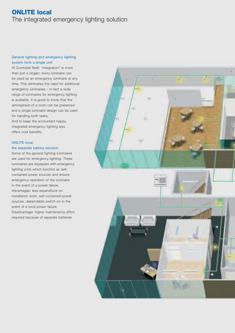
ONLITE local The integrated emergency lighting solution
General lighting and emergency lighting
system form a single unit
At Zumtobel Staff, “integration” is more
than just a slogan: every luminaire can
be used as an emergency luminaire at any
time. This eliminates the need for additional
emergency luminaires – in fact a wide
range of luminaires for emergency lighting
is available. It is good to know that the
atmosphere of a room can be preserved
and a single luminaire design can be used
for handling both tasks.
And to keep the accountant happy,
integrated emergency lighting also
offers cost benefits.
ONLITE local,
the separate battery solution
Some of the general lighting luminaires
are used for emergency lighting. These
luminaires are equipped with emergency
lighting units which function as self-
contained power sources and ensure
emergency operation of the luminaire
in the event of a power failure.
Advantages: less expenditure on
installation work, self-contained power
sources, dependable switch-on in the
event of a local power failure.
Disadvantage: higher maintenance effort
required because of separate batteries

O N L I T E L O C A L 27

ONLITE local The new, revolutionary separate battery power supply
In the case of separate battery luminaires, the battery is always located in the luminaire itself and supplies the lamp with energy
in emergency operating mode. ONLITE has now introduced a revolutionary separate battery in which the latest battery technology,
together with an intelligent charging system, makes a reduction in battery size of 35 % possible. As a result, the ONLITE range
includes the smallest luminaires available on the market.
ONLITE is based on new battery
technology Nickel metal hydride
instead of nickel cadmium
Conventional luminaires are supplied by
NiCd batteries. The use of heavy metals,
and in particular cadmium, is increasingly
attracting criticism, and a general ban
seems likely.
NiCd NiMh
ONLITE is based on an intelligent
charging system
– 35 % smaller in volume with the same
energy output
– No heavy metals (Cd, Hg, Pb)
– 100 % recyclable
– 15 % better temperature/time behaviour
– Expected battery service life is longer
– Faster charging after test
TRICKLE CHARGE
is the intelligent charging system:
– Full capacity available within 7 hours
– Charging is controlled by microprocessor
controller
– Logic circuitry for fast charging (7 h)
– Smart normal charging (0–7 h)
350
300
250
200
150
100
50
0
Time axis
Charging current(mA)
Time axis
3 h version (battery 4.0 Ah)
350
300
250
200
150
100
50
0
1 h version (battery 1.5 Ah)
Charging current(mA)
Installation
Standard battery charge (20 h)
Ready for operation
Trickle charging
Mains fault
Mains supply restored
Fast charge (7 h) Normal charge (0–7 h)
Battery exhaustive discharge
Yes No
Battery supplies lamp, emergency supply duration and battery voltage are monitored
29O N L I T E L O C A L
(furthest luminaire300 m away)
3 FLOOR Luminaires
Luminaires
Luminaires
max
. 30
0 m
Luminaires
rd
2FLOOR
nd
1FLOOR
st
GROUNDFLOOR
SB local checkGSM module
SB 128 local checkcontroller
RS 232 (max. 3 m)
Status Status
Lamp fault
Charging fault
Battery fault
LED
Everything OK
Function test
Annual system test
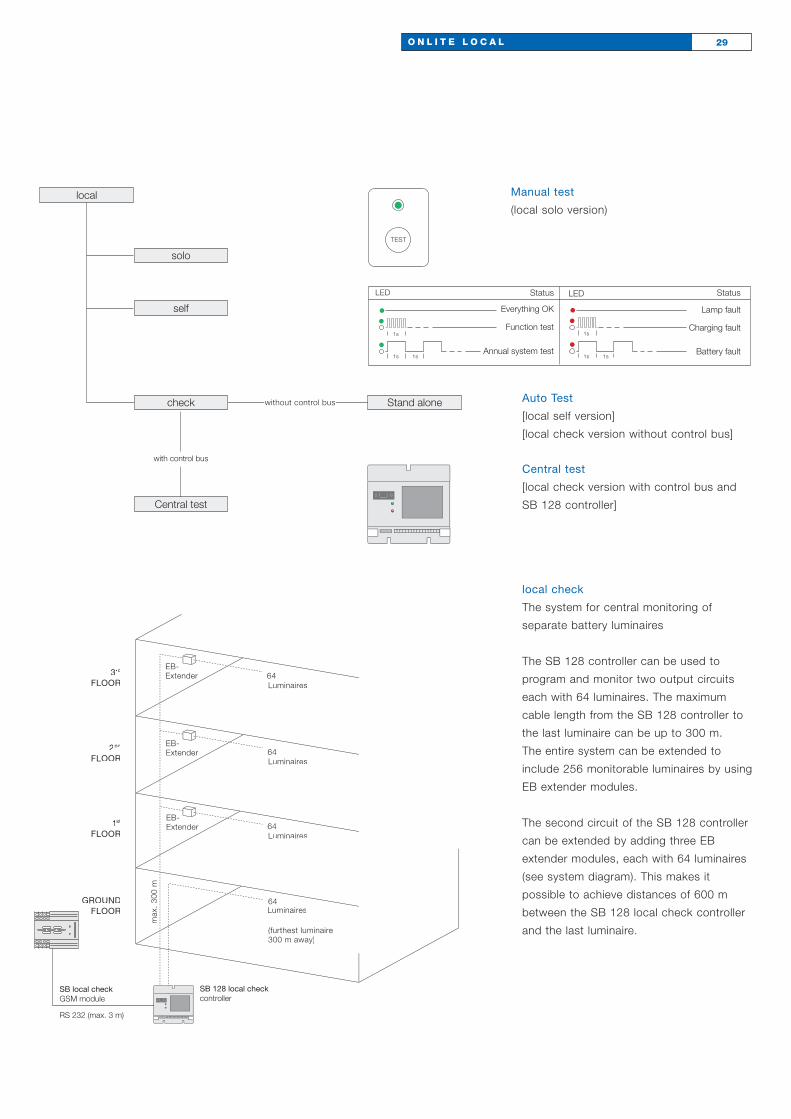
local check
The system for central monitoring of
separate battery luminaires
The SB 128 controller can be used to
program and monitor two output circuits
each with 64 luminaires. The maximum
cable length from the SB 128 controller to
the last luminaire can be up to 300 m.
The entire system can be extended to
include 256 monitorable luminaires by using
EB extender modules.
The second circuit of the SB 128 controller
can be extended by adding three EB
extender modules, each with 64 luminaires
(see system diagram). This makes it
possible to achieve distances of 600 m
between the SB 128 local check controller
and the last luminaire.
local
solo
self
Stand alonewithout control bus
Central test
check
with control bus
Manual test
(local solo version)
Auto Test
[local self version]
[local check version without control bus]
Central test
[local check version with control bus and
SB 128 controller]

ONLITE local check The SB 128 controller monitors, displays and logs
For central monitoring and programming
of local check version separate battery
emergency luminaires. The luminaires are
connected to the SB 128 controller via a
2-wire control bus.
– 128 local check luminaires can be
monitored as standard
– Central logging of lamp or battery
faults in a built-in test book over a
2-year period
– Touch-sensitive screen operation and
programming with backlit graphical
display
– Clock and calendar function for
programming of tests (weekly function
test and annual system test are set by
default)
– Three floating signalling contacts are
available
– Power supply for two output circuits
is built in
– Two RS 232 interfaces on the front for
Notebook connection on terminal strip
for optional modules such as GSM
modules
– TCP/IP connection to building bus
– Optional EB extender modules allow
expansion in order to monitor up to
256 luminaires
RS 232 (max. 3m)Mains
Mains
64 luminaires (furthest luminaire up to 300 m/1.5 mm2 away)
64 luminaires (furthest luminaire up to 300 m/1.5 mm2 away)
SB 128 Power Supply GSM module
31O N L I T E L O C A L C H E C K
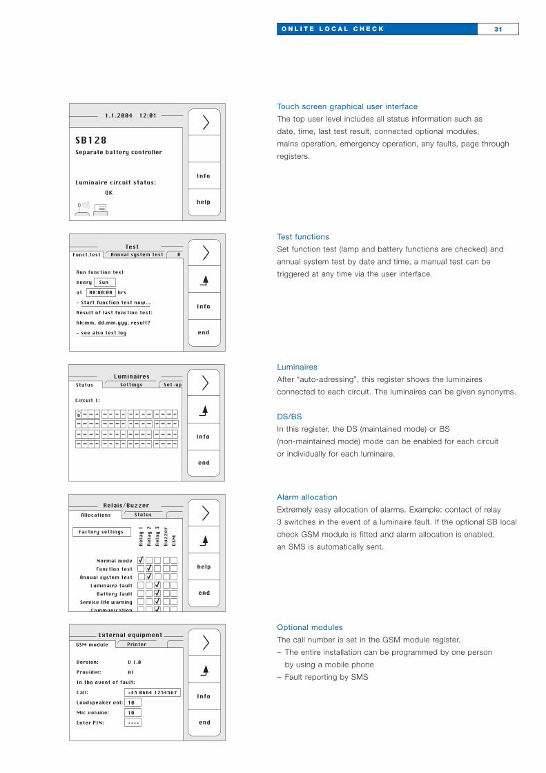
Touch screen graphical user interface
The top user level includes all status information such as
date, time, last test result, connected optional modules,
mains operation, emergency operation, any faults, page through
registers.
Info
help
Separate battery controller
Luminaire circuit status:
OK
1.1.2004 12:01
SB128
Run function test
every Sun
at 00:00:00 hrs
- Start function test now...
Result of last function test:
hh:mm, dd.mm.yyy, result?
- see also test log
Info
end
TestAnnual system test RFunct.test
Circuit 1:
Info
end
LuminairesSettings Set-upStatus
Factory settings
help
end
StatusAllocations
Relais/Buzzer
Normal modeFunction test
Annual system testLuminaire fault
Battery faultService life warning
Communication
Rela
y 1
Rela
y 2
Rela
y 3
Buzz
erGS
M
Version:
Provider:
In the event of fault:
Call:
Loudspeaker vol:
Mic volume:
Enter PIN:
Info
end
PrinterGSM module
External equipment
V 1.0
A1
+43 0664 1234567
10
10
++++
Alarm allocation
Extremely easy allocation of alarms. Example: contact of relay
3 switches in the event of a luminaire fault. If the optional SB local
check GSM module is fitted and alarm allocation is enabled,
an SMS is automatically sent.
Test functions
Set function test (lamp and battery functions are checked) and
annual system test by date and time, a manual test can be
triggered at any time via the user interface.
Luminaires
After “auto-adressing”, this register shows the luminaires
connected to each circuit. The luminaires can be given synonyms.
DS/BS
In this register, the DS (maintained mode) or BS
(non-maintained mode) mode can be enabled for each circuit
or individually for each luminaire.
Optional modules
The call number is set in the GSM module register.
– The entire installation can be programmed by one person
by using a mobile phone
– Fault reporting by SMS
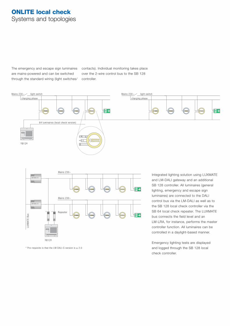
ONLITE local checkSystems and topologies
The emergency and escape sign luminaires
are mains-powered and can be switched
through the standard wiring (light switches/
contacts). Individual monitoring takes place
over the 2-wire control bus to the SB 128
controller.
Mains 230~
64 luminaires ( local check version)
l ight switch
charging phase
Mains 230~ light switch
charging phase
SB128
Integrated lighting solution using LUXMATE
and LM-DALI gateway and an additional
SB 128 controller. All luminaires (general
lighting, emergency and escape sign
luminaires) are connected to the DALI
control bus via the LM-DALI as well as to
the SB 128 local check controller via the
SB 64 local check repeater. The LUXMATE
bus connects the field level and an
LM-LRA, for instance, performs the master
controller function. All luminaires can be
controlled in a daylight-based manner.
Emergency lighting tests are displayed
and logged through the SB 128 local
check controller.
LM DALI-S
Mains 230~
LM DALI-S
Mains 230~
LUXM
ATE
Bus
SB128
Repeater* *
* Pre-requisite is that the LM DALI-S version is ≥ 2.0
O N L I T E L O C A L C H E C K T O P O L O G I E S 33

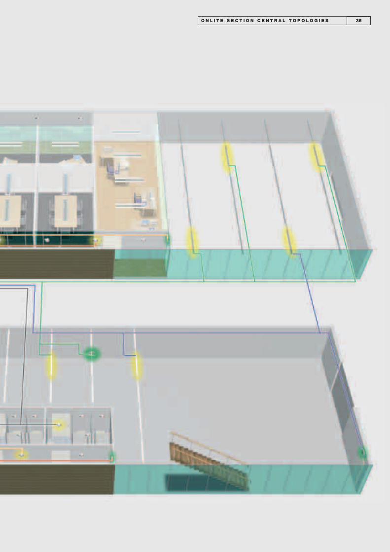
ONLITE central The integrated emergency lighting solution
Each general lighting luminaire is also
a potential emergency luminaire
At Zumtobel Staff, “integration” is more
than just a slogan: every luminaire can be
used as an emergency luminaire at any
time. This eliminates the need for additional
emergency luminaires – in fact a wide
range of luminaires for emergency lighting
is available. It is good to know that the
atmosphere of a room can be preserved
and a single luminaire design can be used
for handling both tasks.
And to keep the accountant happy,
integrated emergency lighting also
offers cost benefits.
ONLITE central, central supply for
emergency luminaires
Some of the mains-powered luminaires are
earmarked for emergency lighting. They are
connected to the section central emer-
gency power source and are supplied by
the latter in the event of a power failure.
The emergency luminaires are assigned
to at least two circuits so that one circuit
remains intact even if the other one fails.
Maximum safety is achieved if all emer-
gency luminaires which are located in the
same fire compartment are supplied and
monitored by an autonomous emergency
power source.
O N L I T E S E C T I O N C E N T R A L T O P O L O G I E S 35
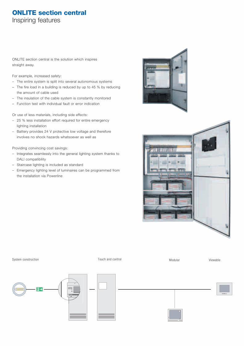
ONLITE section central Inspiring features
ONLITE section central is the solution which inspires
straight away.
For example, increased safety:
– The entire system is split into several autonomous systems
– The fire load in a building is reduced by up to 45 % by reducing
the amount of cable used
– The insulation of the cable system is constantly monitored
– Function test with individual fault or error indication
Or use of less materials, including side effects:
– 25 % less installation effort required for entire emergency
lighting installation
– Battery provides 24 V protective low voltage and therefore
involves no shock hazards whatsoever as well as
Providing convincing cost savings:
– Integrates seamlessly into the general lighting system thanks to
DALI compatibility
– Staircase lighting is included as standard
– Emergency lighting level of luminaires can be programmed from
the installation via Powerline
System construction Touch and control Modular Viewable

The only practical way of carry-
ing this out with self contained
luminaires is via an automated,
preferably fully addressable test
system. Manual keyswitch test
regimes are no longer a viable
option. Automated systems will
quickly and clearly highlight any
shortfalls in the quality of the
emergency lighting equipment
so nothing but the best equip-
ment should be considered.
However, perhaps the largest
effect heralded by these new
systems will be the change in
attitudes towards self contained
solutions. What were once con-
sidered to be fit and forget
systems will now be shown to
be in need of constant and
diligent testing, logging and
maintenance. Nickel cadmium
batteries which, even in the
best designed luminaires,
should be changed every
3–4 years will be highlighted
as requiring huge ongoing
maintenance effort.
The potential for alternative
systems is clear.
ONLITE Section Central con-
sists of a fully self-contained
low power system in a compact
housing. Each system is de-
signed to operate a floor or part
of a building as a separate
safety area. Section Central
does not require the provision
of special rooms or ventilation.
The system delivers 230 V AC
in normal operating mode and
220 V DC during mains failure.
Luminaires can be set to
operate in maintained or non-
maintained modes. Luminaires
equipped with One4All high
frequency ballasts are capable
of operating on AC or DC.
In DC operation the light output
of each luminaire can be set at
the touch panel within each
Section Central.
Communication with the lumi-
naires takes place over the
standard mains supply lines
which, via an interface, also
monitor the luminaires for
correct operation. Individual
luminaires are addressed,
controlled and monitored from
a control panel in each section
central.
Advantages
• Increased safety by splitting
emergency supply into several
autonomous systems in
individual fire compartments
or floors
• Minimised fire load by reduc-
ing the amount of cable used
• Fewer wall openings necessi-
tating fire barriers, resulting in
drastic savings
• No extra or specialist rooms
required to accommodate
batteries
• Easy to extend by adding
extra systems
But perhaps the greatest
advantage
• Huge reduction in ongoing
testing and maintenance effort
and cost
The ongoing maintenance
requirement for Section Central
is, compared to self-contained,
negligible.
37O N L I T E S E C T I O N C E N T R A L

t
+
-
+ – + –
t
+
-
Testing and maintanance
Self Contained emergency
lighting has, for many years,
been the solution of first
choice for the UK market.
There are many reasons for
this not least of which is the
perceived lowest possible cost
of self contained solutions. In
terms of planning, capital pur-
chase and installation cost there
is no doubt that self contained
emergency lighting solutions
offer attractive benefits in the
short term.
However, this is only part of
the story. Whilst there has been
a temptation in the past to
consider emergency lighting as
a fit and forget solution, recent
legislation has passed responsi-
bility firmly back into the hands
of the building owner/occupier.
Via mandatory risk assessment
the owner/occupiers responsi-
bilities have now become crystal
clear. Not only has he the
responsibility to ensure that the
emergency lighting is suitable
and sufficient but the risk
assessment will also show that
procedures must be put in
place and carried out that en-
sure the ongoing testing,
logging and maintenance of
the emergency lighting.
There is little recognition of the true, ongoing cost of performing proper emergency lighting testing and maintenance.Whilst automated and centralised systems may initially cost more, ongoing costs can be decimated.
Without proper emergency lighting testing and maintenance the safety of the building dwindles over time.
39O N L I T E S E C T I O N C E N T R A L
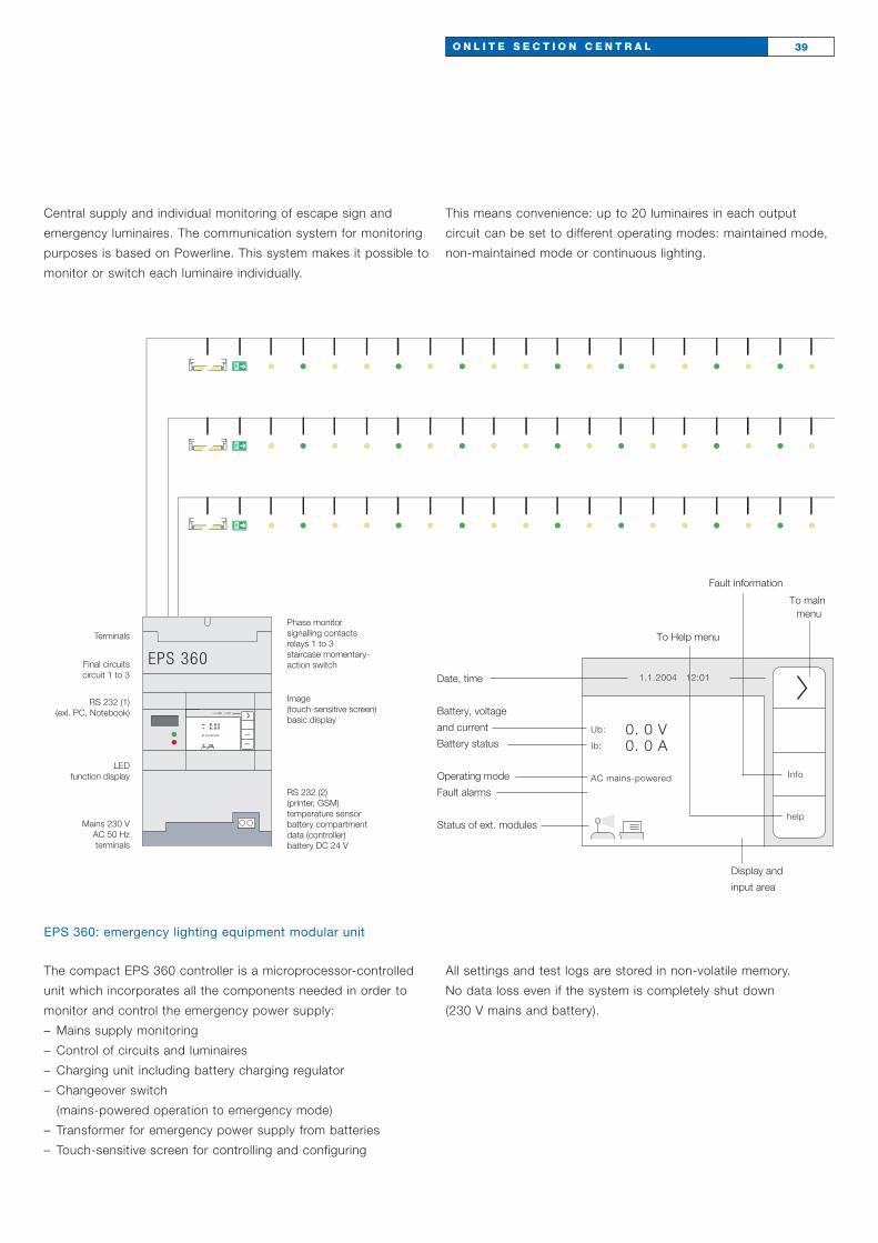
Central supply and individual monitoring of escape sign and
emergency luminaires. The communication system for monitoring
purposes is based on Powerline. This system makes it possible to
monitor or switch each luminaire individually.
This means convenience: up to 20 luminaires in each output
circuit can be set to different operating modes: maintained mode,
non-maintained mode or continuous lighting.
EPS 360
info
hilfe
Ub:
Ib:
AC Netzbetrieb
1.4.2002 12:01
0. 0 V0. 0 A
Terminals
Final circuits circuit 1 to 3
RS 232 (1)(exl. PC, Notebook)
LED function display
Mains 230 V AC 50 Hz terminals
Phase monitor signalling contacts relays 1 to 3staircase momentary-action switch
Image (touch-sensitive screen) basic display
RS 232 (2) (printer, GSM)temperature sensorbattery compartmentdata (controller)battery DC 24 V
Info
help
Ub:
Ib:
AC mains-powered
1.1.2004 12:01
0. 0 V0. 0 A
Display and
input area
Date, time
Battery, voltage
and current
Battery status
Operating mode
Fault alarms
Status of ext. modules
To main menu
Fault information
To Help menu
EPS 360: emergency lighting equipment modular unit
The compact EPS 360 controller is a microprocessor-controlled
unit which incorporates all the components needed in order to
monitor and control the emergency power supply:
– Mains supply monitoring
– Control of circuits and luminaires
– Charging unit including battery charging regulator
– Changeover switch
(mains-powered operation to emergency mode)
– Transformer for emergency power supply from batteries
– Touch-sensitive screen for controlling and configuring
All settings and test logs are stored in non-volatile memory.
No data loss even if the system is completely shut down
(230 V mains and battery).
PLC-DALI PCA
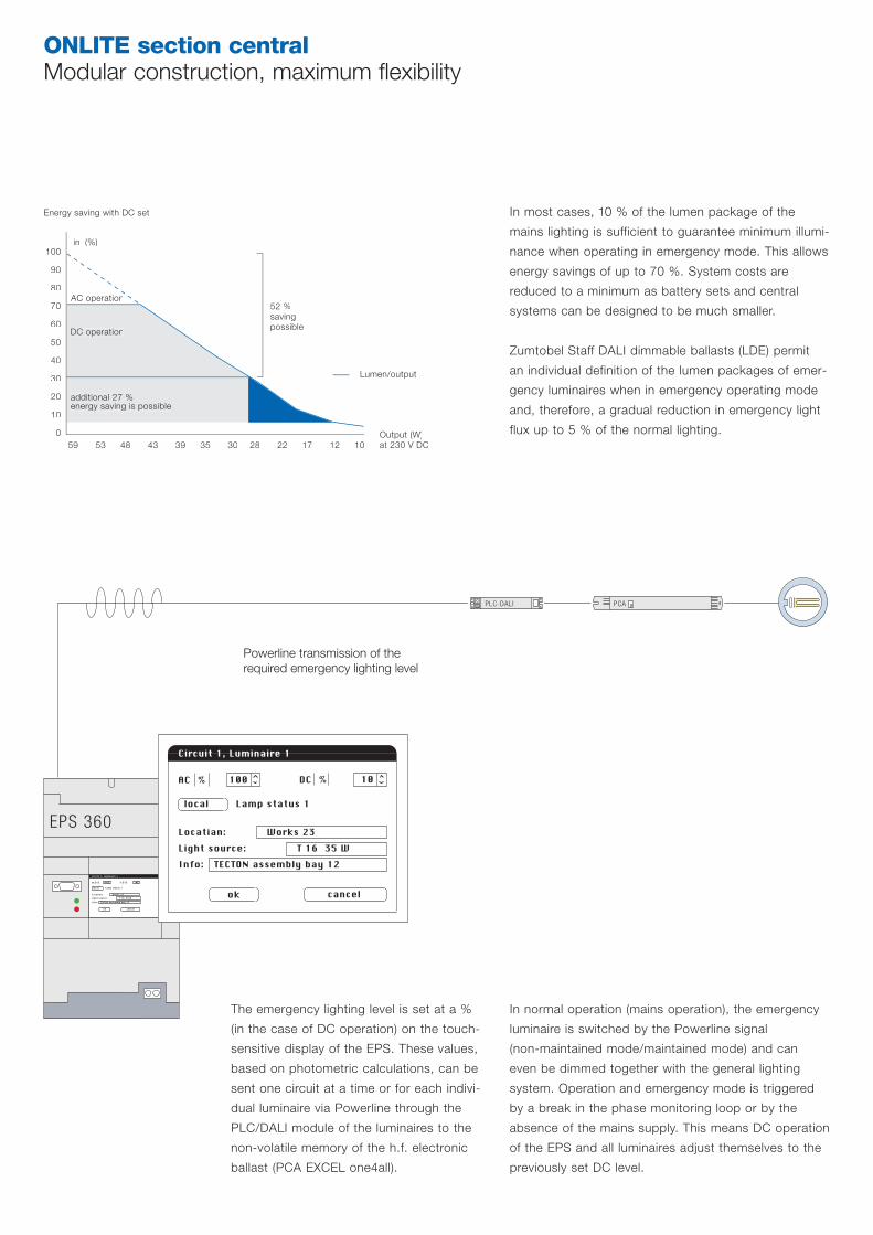
ONLITE section central Modular construction, maximum flexibility
in (%)
Energy saving with DC set
52 %savingpossible
100
90
80
70
60
50
40
30
20
10
0
AC operation
DC operation
additional 27 %energy saving is possible
59 53 48 43 39 35 30 28 22 17 12 10
Lumen/output
Output (W)at 230 V DC
EPS 360
ok cancel
Circuit 1, Luminaire 1
Location: Works 23
Light source: T 16 35 W
Info: TECTON assembly bay 12
100 10AC % IC %
local Lamp status 1
In most cases, 10 % of the lumen package of the
mains lighting is sufficient to guarantee minimum illumi-
nance when operating in emergency mode. This allows
energy savings of up to 70 %. System costs are
reduced to a minimum as battery sets and central
systems can be designed to be much smaller.
Zumtobel Staff DALI dimmable ballasts (LDE) permit
an individual definition of the lumen packages of emer-
gency luminaires when in emergency operating mode
and, therefore, a gradual reduction in emergency light
flux up to 5 % of the normal lighting.
The emergency lighting level is set at a %
(in the case of DC operation) on the touch-
sensitive display of the EPS. These values,
based on photometric calculations, can be
sent one circuit at a time or for each indivi-
dual luminaire via Powerline through the
PLC/DALI module of the luminaires to the
non-volatile memory of the h.f. electronic
ballast (PCA EXCEL one4all).
ok cancel
Circuit 1, Luminaire 1
Locatian: Works 23
Light source: T 16 35 W
Info: TECTON assembly bay 12
100 10AC % DC %
local Lamp status 1
Powerline transmission of the required emergency lighting level
In normal operation (mains operation), the emergency
luminaire is switched by the Powerline signal
(non-maintained mode/maintained mode) and can
even be dimmed together with the general lighting
system. Operation and emergency mode is triggered
by a break in the phase monitoring loop or by the
absence of the mains supply. This means DC operation
of the EPS and all luminaires adjust themselves to the
previously set DC level.
41O N L I T E S E C T I O N C E N T R A L
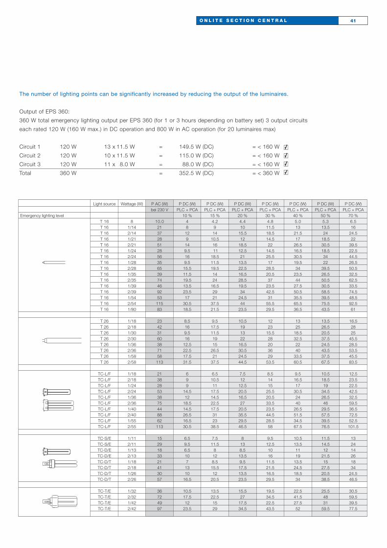
The number of lighting points can be significantly increased by reducing the output of the luminaires.
Output of EPS 360:
360 W total emergency lighting output per EPS 360 (for 1 or 3 hours depending on battery set) 3 output circuits
each rated 120 W (160 W max.) in DC operation and 800 W in AC operation (for 20 luminaires max)
Circuit 1 120 W 13 x 11.5 W = 149.5 W (DC) = < 160 W
Circuit 2 120 W 10 x 11.5 W = 115.0 W (DC) = < 160 W
Circuit 3 120 W 11 x 8.0 W = 88.0 W (DC) = < 160 W
Total 360 W = 352.5 W (DC) = < 360 W
Light source Wattage (W) P AC (W) P DC (W) P DC (W) P DC (W) P DC (W) P DC (W) P DC (W) P DC (W)bei 230 V PLC + PCA PLC + PCA PLC + PCA PLC + PCA PLC + PCA PLC + PCA PLC + PCA
Emergency lighting level 10 % 15 % 20 % 30 % 40 % 50 % 70 %T 16 8 10.0 4 4.2 4.4 4.8 5.0 5.3 6.5T 16 1/14 21 8 9 10 11.5 13 13.5 16T 16 2/14 37 12 14 15.5 18.5 21.5 24 24.5T 16 1/21 28 9 10.5 12 14.5 17 18.5 22T 16 2/21 51 14 16 18.5 22 26.5 30.5 39.5T 16 1/24 28 9.5 11 12.5 14.5 16.5 18.5 22.5T 16 2/24 56 16 18.5 21 25.5 30.5 34 44.5T 16 1/28 35 9.5 11.5 13.5 17 19.5 22 26.5T 16 2/28 65 15.5 19.5 22.5 28.5 34 39.5 50.5T 16 1/35 39 11.5 14 16.5 20.5 23.5 26.5 32.5T 16 2/35 74 19.5 24 28.5 37 44 50.5 62.5T 16 1/39 46 13.5 16.5 19.5 23.5 27.5 30.5 33.5T 16 2/39 92 23.5 29 34 42.5 50.5 58.5 74.5T 16 1/54 53 17 21 24.5 31 35.5 39.5 48.5T 16 2/54 115 30.5 37.5 44 55.5 65.5 75.5 92.5T 16 1/80 83 18.5 21.5 23.5 29.5 36.5 43.5 61
T 26 1/18 23 8.5 9.5 10.5 12 13 13.5 16.5T 26 2/18 42 16 17.5 19 23 25 26.5 28T 26 1/30 31 9.5 11.5 13 15.5 18.5 20.5 25T 26 2/30 60 16 19 22 28 32.5 37.5 45.5T 26 1/36 38 12.5 15 16.5 20 22 24.5 28.5T 26 2/36 71 22.5 26.5 30.5 36 40 43.5 53.5T 26 1/58 58 17.5 21 24.5 29 33.5 37.5 45.5T 26 2/58 113 31.5 37.5 44.5 53.5 60.5 67.5 83.5
TC-L/F 1/18 21 6 6.5 7.5 8.5 9.5 10.5 12.5TC-L/F 2/18 38 9 10.5 12 14 16.5 18.5 23.5TC-L/F 1/24 28 9 11 12.5 15 17 19 22.5TC-L/F 2/24 53 14.5 17.5 20.5 25.5 30.5 34.5 42.5TC-L/F 1/36 38 12 14.5 16.5 20.5 24 26.5 32.5TC-L/F 2/36 75 18.5 22.5 27 33.5 40 46 59.5TC-L/F 1/40 44 14.5 17.5 20.5 23.5 26.5 29.5 36.5TC-L/F 2/40 88 26.5 31 35.5 44.5 51.5 57.5 72.5TC-L/F 1/55 62 16.5 23 29.5 28.5 34.5 39.5 52.5TC-L/F 2/55 113 30.5 38.5 46.5 58 67.5 76.5 101.5
TC-S/E 1/11 15 6.5 7.5 8 9.5 10.5 11.5 13TC-S/E 2/11 29 9.5 11.5 13 12.5 13.5 14.5 24TC-D/E 1/13 18 6.5 8 8.5 10 11 12 14TC-D/E 2/13 33 10 12 13.5 16 19 21.5 26TC-D/T 1/18 21 7 8.5 9.5 11.5 13.5 15 18TC-D/T 2/18 41 13 15.5 17.5 21.5 24.5 27.5 34TC-D/T 1/26 30 10 12 13.5 16.5 18.5 20.5 24.5TC-D/T 2/26 57 16.5 20.5 23.5 29.5 34 38.5 46.5
TC-T/E 1/32 36 10.5 13.5 15.5 19.5 22.5 25.5 30.5TC-T/E 2/32 72 17.5 22.5 27 34.5 41.5 48 59.5TC-T/E 1/42 49 12 15 17.5 22.5 27.5 31 39.5TC-T/E 2/42 97 23.5 29 34.5 43.5 52 59.5 77.5

ONLITE section centralA look at system topologies
The emergency luminaires are centrally supplied and individually
monitored, they are switched with the general lighting system
through switching inputs (S1 and S2).
Mains 230~ Light switch 1
EPS 360
Light switch 2
Mains 230~ Light switch 3
Light switch 4
PLC-DALI
PLC-DALI
PLC-DALI
PLC-DALI
Mains 230~
EPS 360
Mains 230~
PLC-DALI PLC-DALI
Here the emergency luminaires are individually monitored by the
PLC/DALI module and can be switched together with the general
lighting system via the switching input of the PLC/DALI module.

O N L I T E S E C T I O N C E N T R A L T O P O L O G I E S 43
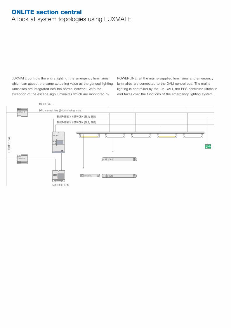
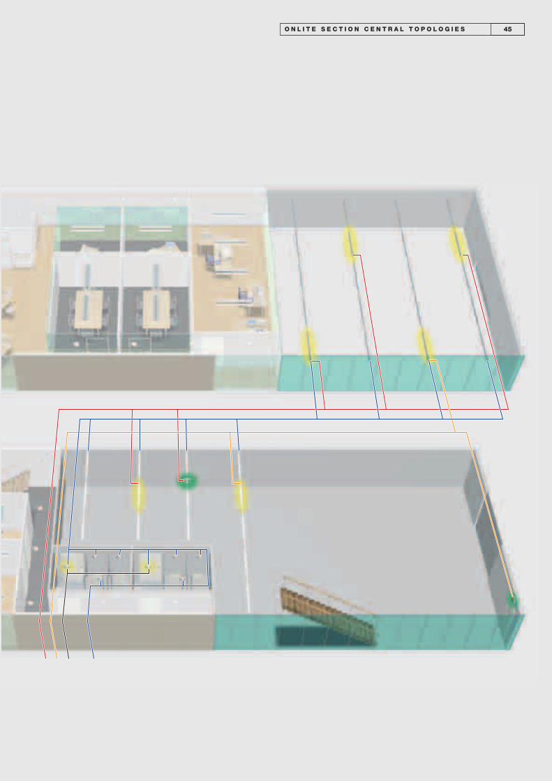
ONLITE section centralA look at system topologies using LUXMATE
LUXMATE controls the entire lighting, the emergency luminaires
which can accept the same actuating value as the general lighting
luminaires are integrated into the normal network. With the
exception of the escape sign luminaires which are monitored by
POWERLINE, all the mains-supplied luminaires and emergency
luminaires are connected to the DALI control bus. The mains
lighting is controlled by the LM-DALI, the EPS controller listens in
and takes over the functions of the emergency lighting system.
LM DALI-S
LM DALI-S
Mains 230~
DALI control l ine (64 luminaires max.)
EMERGENCY NETWORK (EL1; EN1)
EMERGENCY NETWORK (EL2; EN2)
LUXM
ATE
Bus
PCA
PLC-DALI PCA
EPS 360
Control ler EPS
O N L I T E S E C T I O N C E N T R A L T O P O L O G I E S 45
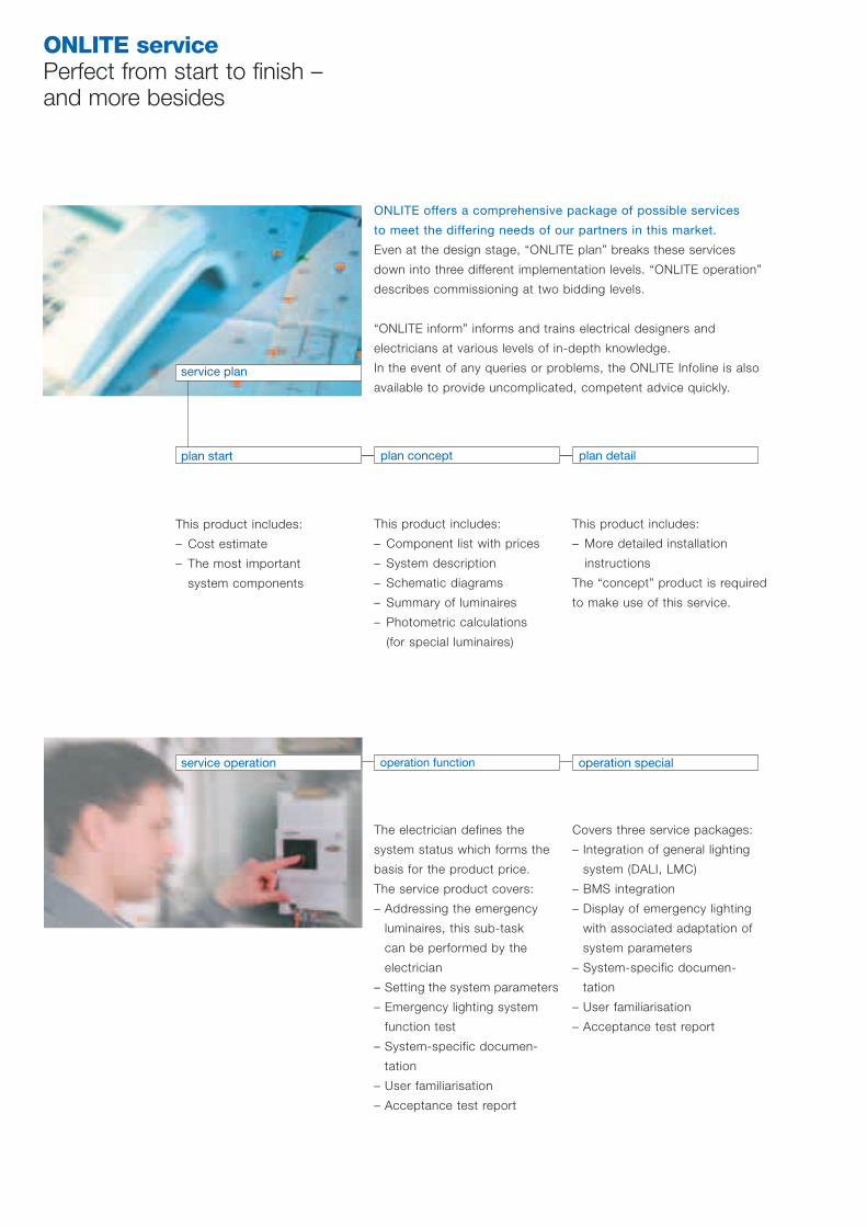
ONLITE servicePerfect from start to finish – and more besides
ONLITE offers a comprehensive package of possible services
to meet the differing needs of our partners in this market.
Even at the design stage, “ONLITE plan” breaks these services
down into three different implementation levels. “ONLITE operation”
describes commissioning at two bidding levels.
“ONLITE inform” informs and trains electrical designers and
electricians at various levels of in-depth knowledge.
In the event of any queries or problems, the ONLITE Infoline is also
available to provide uncomplicated, competent advice quickly.
plan start plan concept plan detail
This product includes:
– Cost estimate
– The most important
system components
This product includes:
– Component list with prices
– System description
– Schematic diagrams
– Summary of luminaires
– Photometric calculations
(for special luminaires)
This product includes:
– More detailed installation
instructions
The “concept” product is required
to make use of this service.
service operation operation function operation special
The electrician defines the
system status which forms the
basis for the product price.
The service product covers:
– Addressing the emergency
luminaires, this sub-task
can be performed by the
electrician
– Setting the system parameters
– Emergency lighting system
function test
– System-specific documen-
tation
– User familiarisation
– Acceptance test report
Covers three service packages:
– Integration of general lighting
system (DALI, LMC)
– BMS integration
– Display of emergency lighting
with associated adaptation of
system parameters
– System-specific documen-
tation
– User familiarisation
– Acceptance test report
service plan
47O N L I T E S E R V I C E
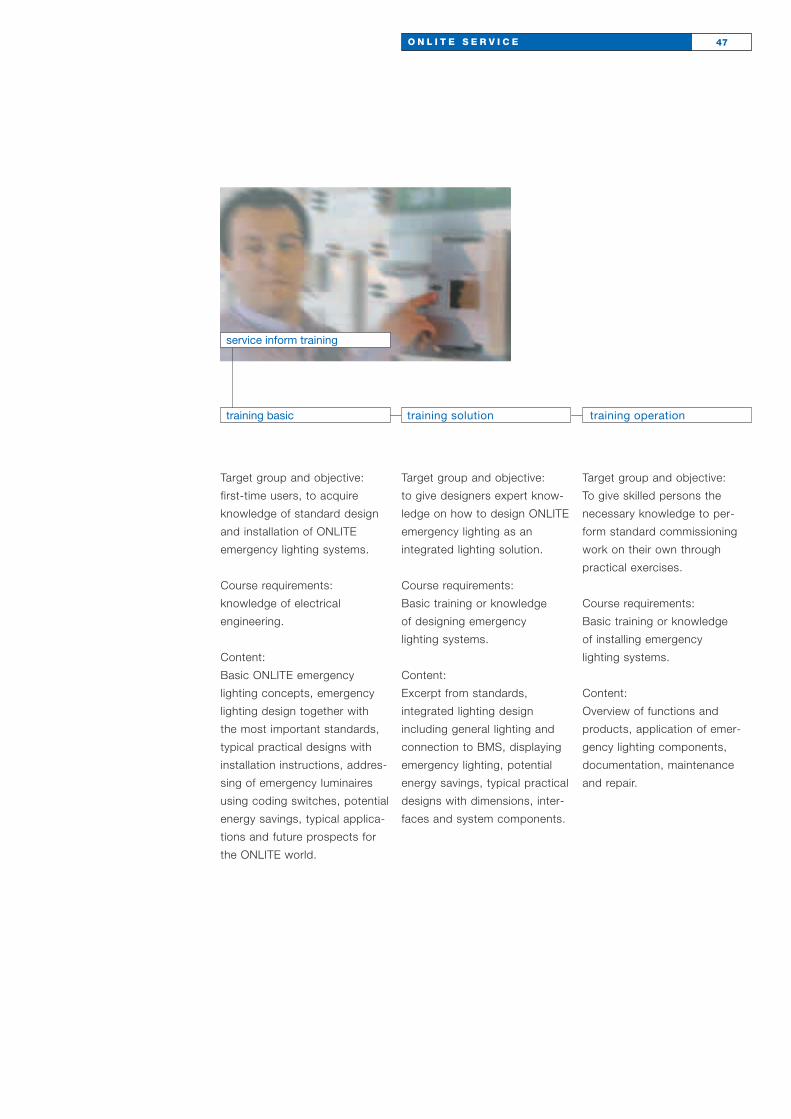
service inform training
Target group and objective:
first-time users, to acquire
knowledge of standard design
and installation of ONLITE
emergency lighting systems.
Course requirements:
knowledge of electrical
engineering.
Content:
Basic ONLITE emergency
lighting concepts, emergency
lighting design together with
the most important standards,
typical practical designs with
installation instructions, addres-
sing of emergency luminaires
using coding switches, potential
energy savings, typical applica-
tions and future prospects for
the ONLITE world.
Target group and objective:
to give designers expert know-
ledge on how to design ONLITE
emergency lighting as an
integrated lighting solution.
Course requirements:
Basic training or knowledge
of designing emergency
lighting systems.
Content:
Excerpt from standards,
integrated lighting design
including general lighting and
connection to BMS, displaying
emergency lighting, potential
energy savings, typical practical
designs with dimensions, inter-
faces and system components.
Target group and objective:
To give skilled persons the
necessary knowledge to per-
form standard commissioning
work on their own through
practical exercises.
Course requirements:
Basic training or knowledge
of installing emergency
lighting systems.
Content:
Overview of functions and
products, application of emer-
gency lighting components,
documentation, maintenance
and repair.
training basic training solution training operation
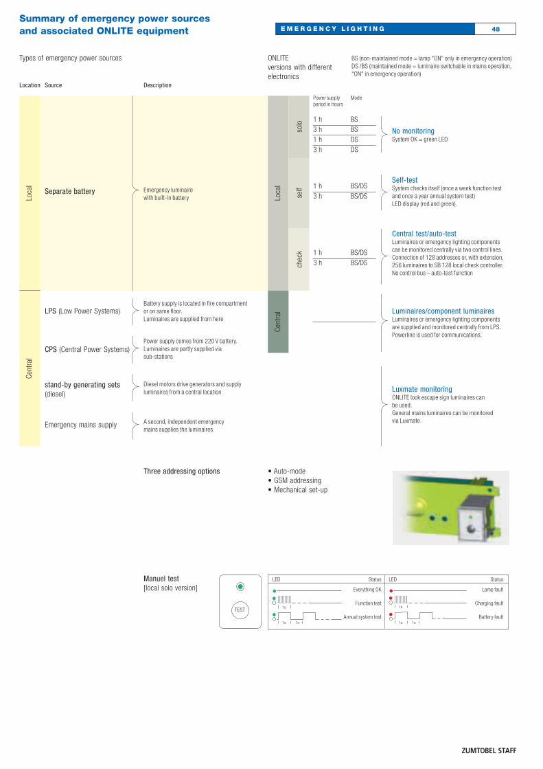
No monitoringSystem OK = green LED
Self-testSystem checks itself (once a week function testand once a year annual system test) LED display (red and green).
Central test/auto-testLuminaires or emergency lighting componentscan be monitored centrally via two control lines.Connection of 128 addresses or, with extension,256 luminaires to SB 128 local check controller.No control bus – auto-test function
Luminaires/component luminairesLuminaires or emergency lighting componentsare supplied and monitored centrally from LPS.Powerline is used for communications.
Luxmate monitoringONLITE look escape sign luminaires can be used.General mains luminaires can be monitored via Luxmate.
Loca
lCe
ntra
l
ONLITEversions with differentelectronics
solo
self
chec
k
BS (non-maintained mode = lamp "ON" only in emergency operation)DS /BS (maintained mode = luminaire switchable in mains operation,"ON" in emergency operation)
Power supply period in hours
Mode
1 h3 h1 h3 h
BSBSDSDS
1 h3 h
BS/DSBS/DS
BS/DSBS/DS
1 h3 h
Types of emergency power sources
Source
Separate battery
LPS (Low Power Systems)
CPS (Central Power Systems)
stand-by generating sets (diesel)
Description
Emergency luminaire with built-in battery
Battery supply is located in fire compartment or on same floor.Luminaires are supplied from here
Power supply comes from 220 V battery.Luminaires are partly supplied via sub-stations
Diesel motors drive generators and supply luminaires from a central location
A second, independent emergency mains supplies the luminaires
Loca
lCe
ntra
l
Location
Emergency mains supply
Summary of emergency power sources and associated ONLITE equipment
• Auto-mode• GSM addressing• Mechanical set-up
Three addressing options
Manuel test[local solo version]
LED Status
Everything OK
Function test
Annual system test
LED Status
Lamp fault
Charging fault
Battery faultTEST
48E M E R G E N C Y L I G H T I N G

ONLITE LOOK ARTSIGN
ONLITE LOOK ARTSIGN EW wall-recessed csRecessed wall luminaire with cover insilver• Recessed housing made of extruded
aluminium section• Power LED (high-output version)
luminance 200 cd/m2
• Chip on board LEDs (low-output version) luminance approx. 70 cd/m2
• Central monitoring via Powerline, noadditional control line required
• Escape signs must be ordered separately
• Voltage: central supply 220/240 V ACand 220 V DC (central)
Cat. no. EL/EB/ET kg Order no.
With high-output central supplyARTSIGN central EW-HO* 185/116/53 0.6 42 156 905
With low-output central supplyARTSIGN central EW-LO** 185/116/53 0.6 42 156 904
ARTSIGN UK self containedARTSIGN UK self contained with self test 185/116/53 0.6 75 644 385
High-output version EN 1838 and DIN 4844, low output EN 1838.* Suitable for UK - Section Central version** Not suitable for UK
170 ± 1
105
± 1
116
51
1,8
186
1818
18
23
850 °C
ONLITE LOOK ARTSIGN EW escape sign
Escape sign• Panel made of diffuser pearl material
and screen-printed escape signaccording to direction
Cat. no. L/W/H kg Order no.
Escape signARTSIGN EW GK transparent for special pictogram 186/116/2 0.1 22 156 911ARTSIGN EW RZ-1L single-sided pointing left 186/116/2 0.1 22 156 909ARTSIGN EW RZ-1R single-sided pointing right 186/116/2 0.1 22 156 910ARTSIGN EW RZ-1U single-sided pointing down 186/116/2 0.1 22 156 908
* Choose left or right by turning cover.
186
116
Cover15mEN 1838
49E M E R G E N C Y L I G H T I N G
50E M E R G E N C Y L I G H T I N GONLITE LOOK ARTSIGN
• Required for installation in solid wallsor concrete walls
• Prepared for tube installation• Housing made of sheet steel with
cover• Used for exposed concrete ceilings,
but also for subsequent plaster work
Cat. no. L/W/H kg Order no.
Concrete casting surroundARTSIGN EW GEH CONCRETE 169/157/60 0.4 22 159 969
60
106,
5
169
156,
5
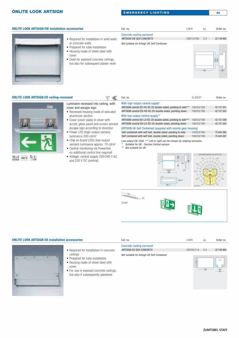
ONLITE LOOK ARTSIGN ED ceiling-recessed csLuminaire recessed into ceiling, withcover and escape sign• Recessed housing made of extruded
aluminium section• Cover (cover plate) in silver with
acrylic glass panel and screen-printedescape sign according to direction
• Power LED (high-output version) luminance 200 cd/m2
• Chip on board LEDs (low-output version) luminance approx. 70 cd/m2
• Central monitoring via Powerline,no additional control line required
• Voltage: central supply 220/240 V ACand 220 V DC (central)
Cat. no. EL/EB/ET Order no.
With high-output central supply*ARTSIGN central ED-HO RZ-2S double-sided, pointing to side*** 180/53/188 42 157 301ARTSIGN central ED-HO RZ-2U double-sided, pointing down 180/53/188 42 157 302
With low-output central supply**ARTSIGN central ED-LO RZ-2S double-sided, pointing to side*** 180/53/188 42 157 299ARTSIGN central ED-LO RZ-2U double-sided, pointing down 180/53/188 42 157 300
ARTSIGN UK Self Contained (supplied with remote gear housing) Self contained with self test, double sided, pointing to side 180/53/188 75 644 386Self contained with self test, double sided, pointing down 180/53/188 75 644 387
Low output EN 1838. *** Left or right can be chosen by rotating luminaire.* Suitable for UK - Section Central version** Not suitable for UK
Not suitable for Artsign UK Self Contained
150,5
186
8344± 110
2
13
2 53
188
169 ± 1
183
45
Cover
15mEN 1838
850 °C
ONLITE LOOK ARTSIGN ED installation accessories
• Required for installation in concreteceilings
• Prepared for tube installation• Housing made of sheet steel with
cover• For use in exposed concrete ceilings,
but also if subsequently plastered
Cat. no. L/W/H kg Order no.
Concrete casting surroundARTSIGN ED GEH CONCRETE 182/93/114 0.5 22 159 968
182
114
9344
ONLITE LOOK ARTSIGN EW installation accessories
Not suitable for Artsign UK Self Contained

Single unit• Reflectors• Die-cast cover• Acrylic panel
COMSIGN stands out thanks to its light,transparent appearance. COMSIGN iseasy to fit in any situation and is com-patible with the TECTON continuous-row lighting system.It is therefore ideal for use in presti-gious interiors from foyers through tooffices and retail areas. Environmentallycompatible because it works with anNiMh battery with no cadmium (which presents difficulties in terms of degra-dation).
COMSIGN – lightweight and transparent
ONLITE LOOK COMSIGN
ONLITE LOOK COMSIGN ED recessed into ceiling csTransparent discs/recessed luminaire• Housing made of polycarbonate• Please order escape signs with white
diffusive cover made of die-cast alu-minium and pictograms separately
• Voltage: individual battery supply220/240 V AC (local), central supply220/240 V AC and 220 V DC (central)
• Assembly parts for recess of basichousing into ceiling included in scopeof supply
Cat. no. L/W/H kg Order no.
Individual battery supply without monitoringCOMSIGN local solo 1/8 W BS 1h 360/66/92 0.8 42 160 257COMSIGN local solo 1/8 W BS 3h 360/66/92 0.9 42 160 258COMSIGN local solo 1/8 W DS 1h 360/66/92 0.8 42 160 259COMSIGN local solo 1/8 W DS 3h 360/66/92 0.9 42 173 719
Individual battery supply with monitoringCOMSIGN local check 1/8 W DS 1h 360/66/92 0.8 42 173 720COMSIGN local check 1/8 W DS 3h * 360/66/92 0.9 42 173 721
With central supplyCOMSIGN central 1/8 W ** 360/66/92 0.5 42 173 722
Tested to 60598-2-22 accor-ding to DIN 4844/EN 1838,suitable for installationsaccording to VDE 0108,ÖVE EN2 and SEV.* Suitable for UK - Self Test
version** Suitable for UK - Section
Central version
260
2,5
152
16
6679
92
69 ± 1
354 ± 1
360T16
850 °Cincl. lamp
51E M E R G E N C Y L I G H T I N G
52E M E R G E N C Y L I G H T I N GONLITE LOOK COMSIGN
ONLITE LOOK COMSIGN ED installation accessories
• Required for installation in concreteceilings
• Prepared for tube installation• Housing made of sheet steel with
cover• For use in exposed concrete ceilings,
but also if subsequently plastered
Cat. no. L/W/H kg Order no.
Concrete casting surroundECOSIGN/COMSIGN GEH CONCRETE 357/164/120 1.3 22 066 751
357 164
120
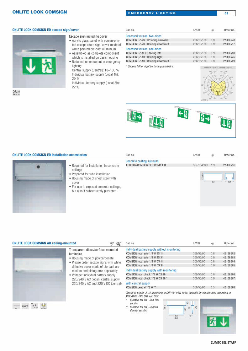
ONLITE LOOK COMSIGN AB ceiling-mounted csTransparent discs/surface-mountedluminaire• Housing made of polycarbonate• Please order escape signs with white
diffusive cover made of die-cast alu-minium and pictograms separately
• Voltage: individual battery supply220/240 V AC (local), central supply220/240 V AC and 220 V DC (central)
Cat. no. L/W/H kg Order no.
Individual battery supply without monitoringCOMSIGN local solo 1/8 W BS 1h 350/55/90 0.8 42 156 882COMSIGN local solo 1/8 W BS 3h 350/55/90 0.9 42 156 883COMSIGN local solo 1/8 W DS 1h 350/55/90 0.8 42 156 884COMSIGN local solo 1/8 W DS 3h 350/55/90 0.9 42 156 885
Individual battery supply with monitoringCOMSIGN local check 1/8 W DS 1h 350/55/90 0.8 42 156 886COMSIGN local check 1/8 W DS 3h * 350/55/90 0.9 42 156 887
With central supplyCOMSIGN central 1/8 W ** 350/55/90 0.5 42 156 888
Tested to 60598-2-22 according to DIN 4844/EN 1838, suitable for installations according to VDE 0108, ÖVE EN2 and SEV.* Suitable for UK - Self Test
version** Suitable for UK - Section
Central version
350260
90
242
16
55
1522,
5
T16850 °C
incl. lamp
ONLITE LOOK COMSIGN ED escape sign/cover
Escape sign including cover• Acrylic glass panel with screen-prin-
ted escape route sign, cover made ofwhite painted die-cast aluminium
• Assembled as complete componentwhich is installed on basic housing
• Reduced lumen output in emergencylighting:Central supply (Central): 10–100 %Individual battery supply (Local 1h):29 % Individual battery supply (Local 3h):22 %
Cat. no. L/W/H kg Order no.
Recessed version, two-sidedCOMSIGN RZ-2S ED* facing sideward 260/16/160 0.9 22 066 240COMSIGN RZ-2U ED facing downward 260/16/160 0.9 22 066 717
Recessed version, one-sidedCOMSIGN RZ-1L ED facing left 260/16/160 0.9 22 066 739COMSIGN RZ-1R ED facing right 260/16/160 0.9 22 066 745COMSIGN RZ-1U ED facing downward 260/16/160 0.9 22 066 723
* Choose left or right by turning luminaire.
26mEN 1838
ONLITE LOOK COMSIGN
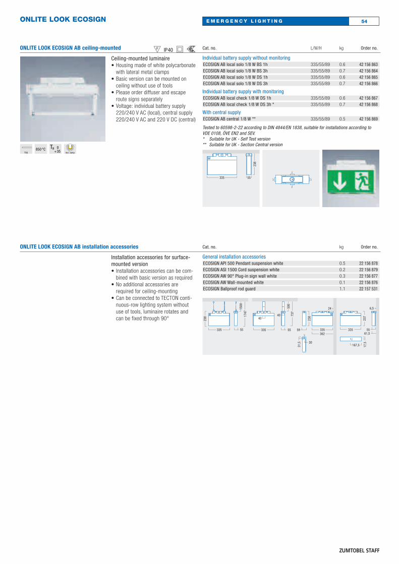
ONLITE LOOK COMSIGN TECTON csTECTON with ONLITE LOOK COMSIGN• Housing made of white polycarbonate• Basic luminaire version in different
electronic variants includes TECTONpendant suspension (module length300 mm)
• Can be connected to TECTON conti-nuous-row lighting system withoutuse of tools, luminaire rotates andcan be fixed through 90°
• Acrylic glass panel with screen-prin-ted escape route sign, cover made ofwhite painted die-cast aluminium
• Voltage: individual battery supply220/240 V AC (local), central supply220/240 V AC and 220 V DC (central)
Cat. no. Order no.
Individual battery supply without monitoring, incl. suspensionCOMSIGN local solo 1/8 W DS 1h TECTON 42 124 636COMSIGN local solo 1/8 W DS 3h TECTON 42 124 642
Individual battery supply with monitoring incl. suspensionCOMSIGN local check 1/8 W DS 1h TECTON 42 124 658COMSIGN local check 1/8 W DS 3h TECTON * 42 124 661
Central supply, incl. suspensionCOMSIGN central 1/8 W TECTON ** 42 124 677
Escape sign and coverCOMSIGN RZ-1L AB to left 22 156 892COMSIGN RZ-1R AB to right 22 156 893COMSIGN RZ-1U AB downwards 22 156 891COMSIGN RZ-2S AB* to page 22 156 890COMSIGN RZ-2U AB downwards 22 156 889
Tested according to 60598-2-22 to DIN 4844/EN 1838, suitable for installations according to VDE 0108, ÖVE EN2 and SEV. Please order acrylic glass panel with escape sign and coverseparately.* Suitable for UK - Self Test
version** Suitable for UK - Section
Central version
350260
327
82
300
235
93T16
850 °Cincl. lamp
ONLITE LOOK COMSIGN AB escape sign/cover
Escape sign including cover• Acrylic glass panel with screen-prin-
ted escape route sign, cover made ofwhite painted die-cast aluminium
• Assembled as complete componentwhich is installed on basic housing
• Reduced lumen output in emergencylighting:Central supply (Central): 10–100 %Individual battery supply (Local 1h):29 % Individual battery supply (Local 3h):22 %
Cat. no. L/W/H kg Order no.
Surface-mounted version, two-sidedCOMSIGN RZ-2S AB* to page 260/16/160 0.8 22 156 890COMSIGN RZ-2U AB downwards 260/16/160 0.8 22 156 889
Surface-mounted version, one-sidedCOMSIGN RZ-1L AB to left 260/16/160 0.8 22 156 892COMSIGN RZ-1R AB to right 260/16/160 0.8 22 156 893COMSIGN RZ-1U AB downwards 260/16/160 0.8 22 156 891
* Choose left or right by turning luminaire.
26mEN 1838
ONLITE LOOK COMSIGN AB installation accessories
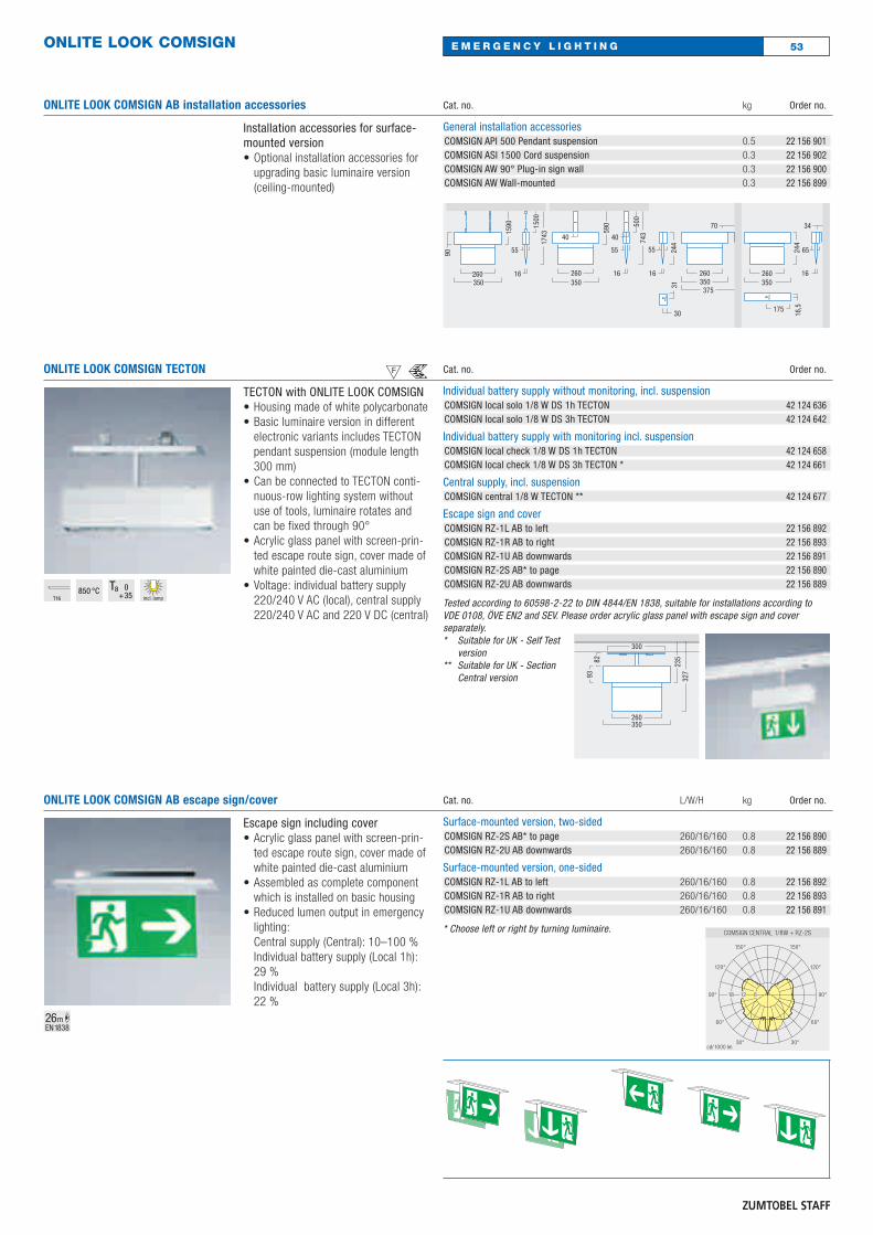
Installation accessories for surface-mounted version• Optional installation accessories for
upgrading basic luminaire version(ceiling-mounted)
Cat. no. kg Order no.
General installation accessoriesCOMSIGN API 500 Pendant suspension 0.5 22 156 901COMSIGN ASI 1500 Cord suspension 0.3 22 156 902COMSIGN AW 90° Plug-in sign wall 0.3 22 156 900COMSIGN AW Wall-mounted 0.3 22 156 899
350260
70
375
16
55 244
350260
590
40
500
743
16
55
40
350260
1590 15
0017
43
16
55 244
350260 16
65
34
90
31
30 16,5175
53E M E R G E N C Y L I G H T I N G
54
ONLITE LOOK ECOSIGN AB installation accessories
Installation accessories for surface-mounted version• Installation accessories can be com-
bined with basic version as required• No additional accessories are
required for ceiling-mounting• Can be connected to TECTON conti-
nuous-row lighting system withoutuse of tools, luminaire rotates andcan be fixed through 90°
Cat. no. kg Order no.
General installation accessoriesECOSIGN API 500 Pendant suspension white 0.5 22 156 878ECOSIGN ASI 1500 Cord suspension white 0.2 22 156 879ECOSIGN AW 90° Plug-in sign wall white 0.3 22 156 877ECOSIGN AW Wall-mounted white 0.1 22 156 876ECOSIGN Ballproof rod guard 1.1 22 157 531
335 55
1747
1500
335
237
55
6,5
61,5
24
335362
59
238
335
40
55
737
40
500
238
31,5 30
17,5
167,5
E M E R G E N C Y L I G H T I N GONLITE LOOK ECOSIGN
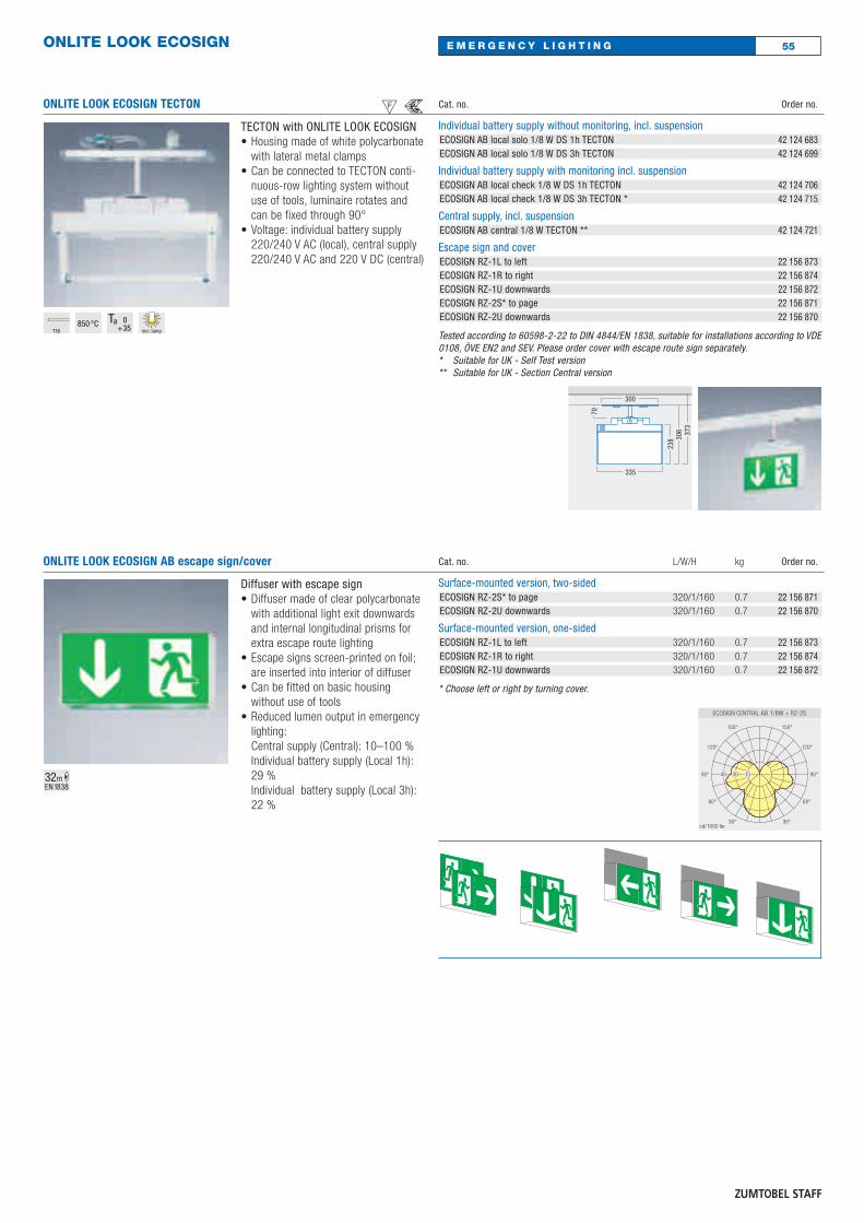
ONLITE LOOK ECOSIGN AB ceiling-mounted chwsCeiling-mounted luminaire• Housing made of white polycarbonate
with lateral metal clamps• Basic version can be mounted on
ceiling without use of tools• Please order diffuser and escape
route signs separately• Voltage: individual battery supply
220/240 V AC (local), central supply220/240 V AC and 220 V DC (central)
Cat. no. L/W/H kg Order no.
Individual battery supply without monitoringECOSIGN AB local solo 1/8 W BS 1h 335/55/89 0.6 42 156 863ECOSIGN AB local solo 1/8 W BS 3h 335/55/89 0.7 42 156 864ECOSIGN AB local solo 1/8 W DS 1h 335/55/89 0.6 42 156 865ECOSIGN AB local solo 1/8 W DS 3h 335/55/89 0.7 42 156 866
Individual battery supply with monitoringECOSIGN AB local check 1/8 W DS 1h 335/55/89 0.6 42 156 867ECOSIGN AB local check 1/8 W DS 3h * 335/55/89 0.7 42 156 868
With central supplyECOSIGN AB central 1/8 W ** 335/55/89 0.5 42 156 869
Tested to 60598-2-22 according to DIN 4844/EN 1838, suitable for installations according to VDE 0108, ÖVE EN2 and SEV.* Suitable for UK - Self Test version** Suitable for UK - Section Central version
335 55
238
T16850 °C
incl. lamp
ONLITE LOOK ECOSIGN
ONLITE LOOK ECOSIGN TECTON csTECTON with ONLITE LOOK ECOSIGN• Housing made of white polycarbonate
with lateral metal clamps• Can be connected to TECTON conti-
nuous-row lighting system withoutuse of tools, luminaire rotates andcan be fixed through 90°
• Voltage: individual battery supply220/240 V AC (local), central supply220/240 V AC and 220 V DC (central)
Cat. no. Order no.
Individual battery supply without monitoring, incl. suspensionECOSIGN AB local solo 1/8 W DS 1h TECTON 42 124 683ECOSIGN AB local solo 1/8 W DS 3h TECTON 42 124 699
Individual battery supply with monitoring incl. suspensionECOSIGN AB local check 1/8 W DS 1h TECTON 42 124 706ECOSIGN AB local check 1/8 W DS 3h TECTON * 42 124 715
Central supply, incl. suspensionECOSIGN AB central 1/8 W TECTON ** 42 124 721
Escape sign and coverECOSIGN RZ-1L to left 22 156 873ECOSIGN RZ-1R to right 22 156 874ECOSIGN RZ-1U downwards 22 156 872ECOSIGN RZ-2S* to page 22 156 871ECOSIGN RZ-2U downwards 22 156 870
Tested according to 60598-2-22 to DIN 4844/EN 1838, suitable for installations according to VDE0108, ÖVE EN2 and SEV. Please order cover with escape route sign separately.* Suitable for UK - Self Test version** Suitable for UK - Section Central version
335
306 37
3
70
300
238
T16850 °C
incl. lamp
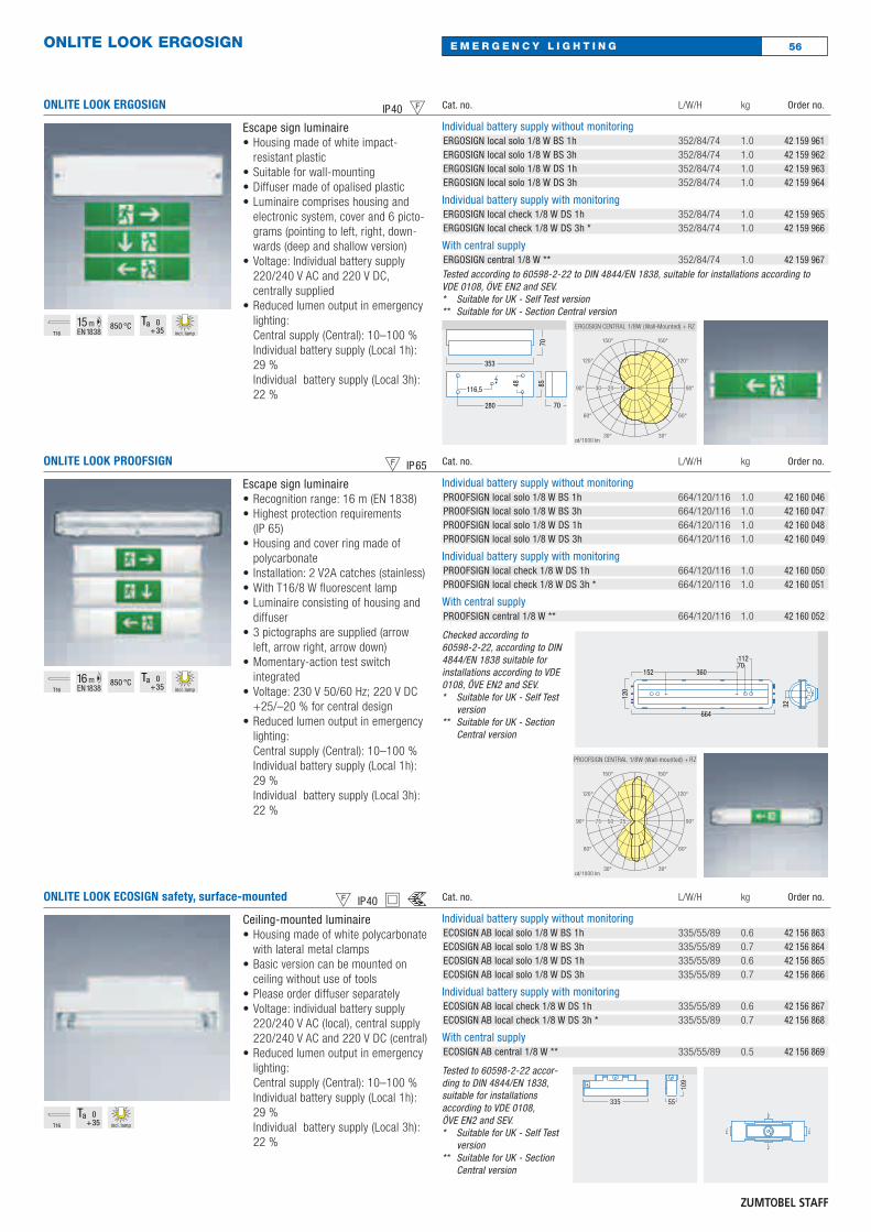
ONLITE LOOK ECOSIGN AB escape sign/cover
Diffuser with escape sign• Diffuser made of clear polycarbonate
with additional light exit downwardsand internal longitudinal prisms forextra escape route lighting
• Escape signs screen-printed on foil;are inserted into interior of diffuser
• Can be fitted on basic housingwithout use of tools
• Reduced lumen output in emergencylighting:Central supply (Central): 10–100 %Individual battery supply (Local 1h):29 % Individual battery supply (Local 3h):22 %
Cat. no. L/W/H kg Order no.
Surface-mounted version, two-sidedECOSIGN RZ-2S* to page 320/1/160 0.7 22 156 871ECOSIGN RZ-2U downwards 320/1/160 0.7 22 156 870
Surface-mounted version, one-sidedECOSIGN RZ-1L to left 320/1/160 0.7 22 156 873ECOSIGN RZ-1R to right 320/1/160 0.7 22 156 874ECOSIGN RZ-1U downwards 320/1/160 0.7 22 156 872
* Choose left or right by turning cover.
32mEN 1838
55E M E R G E N C Y L I G H T I N G
56E M E R G E N C Y L I G H T I N GONLITE LOOK ERGOSIGN
ONLITE LOOK ERGOSIGN hcEscape sign luminaire• Housing made of white impact-
resistant plastic• Suitable for wall-mounting• Diffuser made of opalised plastic• Luminaire comprises housing and
electronic system, cover and 6 picto-grams (pointing to left, right, down-wards (deep and shallow version)
• Voltage: Individual battery supply220/240 V AC and 220 V DC,centrally supplied
• Reduced lumen output in emergencylighting:Central supply (Central): 10–100 %Individual battery supply (Local 1h):29 % Individual battery supply (Local 3h):22 %
Cat. no. L/W/H kg Order no.
Individual battery supply without monitoringERGOSIGN local solo 1/8 W BS 1h 352/84/74 1.0 42 159 961ERGOSIGN local solo 1/8 W BS 3h 352/84/74 1.0 42 159 962ERGOSIGN local solo 1/8 W DS 1h 352/84/74 1.0 42 159 963ERGOSIGN local solo 1/8 W DS 3h 352/84/74 1.0 42 159 964
Individual battery supply with monitoringERGOSIGN local check 1/8 W DS 1h 352/84/74 1.0 42 159 965ERGOSIGN local check 1/8 W DS 3h * 352/84/74 1.0 42 159 966
With central supplyERGOSIGN central 1/8 W ** 352/84/74 1.0 42 159 967Tested according to 60598-2-22 to DIN 4844/EN 1838, suitable for installations according to VDE 0108, ÖVE EN2 and SEV.* Suitable for UK - Self Test version** Suitable for UK - Section Central version
280
353
116,5
48 85
70
70
T16
15mEN 1838
850 °Cincl. lamp
ONLITE LOOK PROOFSIGN cmEscape sign luminaire• Recognition range: 16 m (EN 1838)• Highest protection requirements
(IP 65)• Housing and cover ring made of
polycarbonate• Installation: 2 V2A catches (stainless)• With T16/8 W fluorescent lamp• Luminaire consisting of housing and
diffuser• 3 pictographs are supplied (arrow
left, arrow right, arrow down)• Momentary-action test switch
integrated• Voltage: 230 V 50/60 Hz; 220 V DC
+25/–20 % for central design• Reduced lumen output in emergency
lighting:Central supply (Central): 10–100 %Individual battery supply (Local 1h):29 % Individual battery supply (Local 3h):22 %
Cat. no. L/W/H kg Order no.
Individual battery supply without monitoringPROOFSIGN local solo 1/8 W BS 1h 664/120/116 1.0 42 160 046PROOFSIGN local solo 1/8 W BS 3h 664/120/116 1.0 42 160 047PROOFSIGN local solo 1/8 W DS 1h 664/120/116 1.0 42 160 048PROOFSIGN local solo 1/8 W DS 3h 664/120/116 1.0 42 160 049
Individual battery supply with monitoringPROOFSIGN local check 1/8 W DS 1h 664/120/116 1.0 42 160 050PROOFSIGN local check 1/8 W DS 3h * 664/120/116 1.0 42 160 051
With central supplyPROOFSIGN central 1/8 W ** 664/120/116 1.0 42 160 052
Checked according to 60598-2-22, according to DIN4844/EN 1838 suitable forinstallations according to VDE0108, ÖVE EN2 and SEV.* Suitable for UK - Self Test
version** Suitable for UK - Section
Central version
32
70
664
152 360
112
120T16
16 mEN 1838
850 °Cincl. lamp
ONLITE LOOK ECOSIGN safety, surface-mounted chwsCeiling-mounted luminaire• Housing made of white polycarbonate
with lateral metal clamps• Basic version can be mounted on
ceiling without use of tools• Please order diffuser separately• Voltage: individual battery supply
220/240 V AC (local), central supply220/240 V AC and 220 V DC (central)
• Reduced lumen output in emergencylighting:Central supply (Central): 10–100 %Individual battery supply (Local 1h):29 % Individual battery supply (Local 3h):22 %
Cat. no. L/W/H kg Order no.
Individual battery supply without monitoringECOSIGN AB local solo 1/8 W BS 1h 335/55/89 0.6 42 156 863ECOSIGN AB local solo 1/8 W BS 3h 335/55/89 0.7 42 156 864ECOSIGN AB local solo 1/8 W DS 1h 335/55/89 0.6 42 156 865ECOSIGN AB local solo 1/8 W DS 3h 335/55/89 0.7 42 156 866
Individual battery supply with monitoringECOSIGN AB local check 1/8 W DS 1h 335/55/89 0.6 42 156 867ECOSIGN AB local check 1/8 W DS 3h * 335/55/89 0.7 42 156 868
With central supplyECOSIGN AB central 1/8 W ** 335/55/89 0.5 42 156 869
Tested to 60598-2-22 accor-ding to DIN 4844/EN 1838,suitable for installationsaccording to VDE 0108,ÖVE EN2 and SEV.* Suitable for UK - Self Test
version** Suitable for UK - Section
Central version
335 55
109
T16 incl. lamp
ONLITE LOOK ECOSIGN
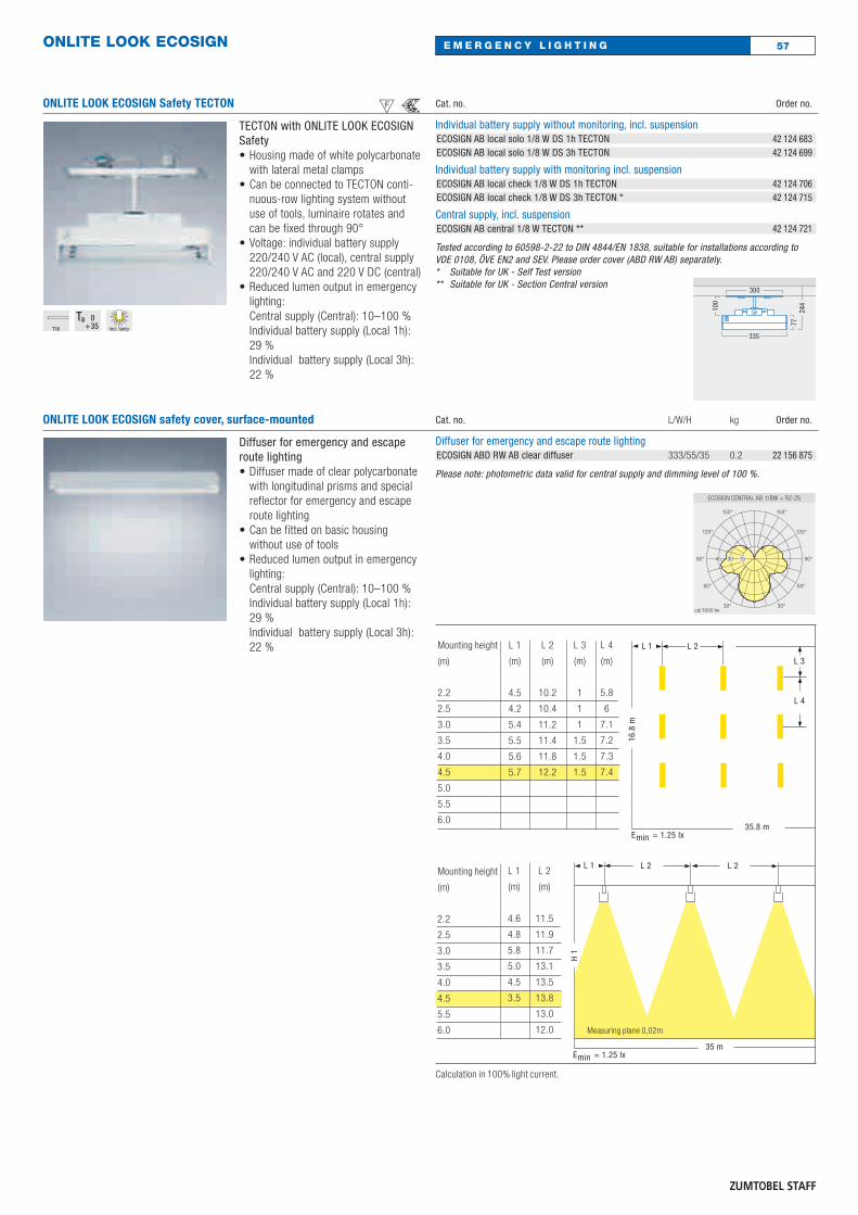
ONLITE LOOK ECOSIGN Safety TECTON csTECTON with ONLITE LOOK ECOSIGNSafety• Housing made of white polycarbonate
with lateral metal clamps• Can be connected to TECTON conti-
nuous-row lighting system withoutuse of tools, luminaire rotates andcan be fixed through 90°
• Voltage: individual battery supply220/240 V AC (local), central supply220/240 V AC and 220 V DC (central)
• Reduced lumen output in emergencylighting:Central supply (Central): 10–100 %Individual battery supply (Local 1h):29 % Individual battery supply (Local 3h):22 %
Cat. no. Order no.
Individual battery supply without monitoring, incl. suspensionECOSIGN AB local solo 1/8 W DS 1h TECTON 42 124 683ECOSIGN AB local solo 1/8 W DS 3h TECTON 42 124 699
Individual battery supply with monitoring incl. suspensionECOSIGN AB local check 1/8 W DS 1h TECTON 42 124 706ECOSIGN AB local check 1/8 W DS 3h TECTON * 42 124 715
Central supply, incl. suspensionECOSIGN AB central 1/8 W TECTON ** 42 124 721
Tested according to 60598-2-22 to DIN 4844/EN 1838, suitable for installations according to VDE 0108, ÖVE EN2 and SEV. Please order cover (ABD RW AB) separately.* Suitable for UK - Self Test version** Suitable for UK - Section Central version
335
244
100
300
77
T16 incl. lamp
Diffuser for emergency and escaperoute lighting• Diffuser made of clear polycarbonate
with longitudinal prisms and specialreflector for emergency and escaperoute lighting
• Can be fitted on basic housingwithout use of tools
• Reduced lumen output in emergencylighting:Central supply (Central): 10–100 %Individual battery supply (Local 1h):29 % Individual battery supply (Local 3h):22 %
Cat. no. L/W/H kg Order no.
Diffuser for emergency and escape route lightingECOSIGN ABD RW AB clear diffuser 333/55/35 0.2 22 156 875
Please note: photometric data valid for central supply and dimming level of 100 %.
2.2
2.5
3.0
3.5
4.0
4.5
5.0
5.5
6.0
L 1
(m)
4.5
4.2
5.4
5.5
5.6
5.7
L 2
(m)
10.2
10.4
11.2
11.4
11.8
12.2
L 3
(m)
1
1
1
1.5
1.5
1.5
L 4
(m)
5.8
6
7.1
7.2
7.3
7.4
L 1 L 2
35.8 m
16.8
m
L 3
L 4
Emin = 1.25 lx
2.2
2.5
3.0
3.5
4.0
4.5
5.5
6.0
L 1
(m)
4.6
4.8
5.8
5.0
4.5
3.5
L 2
(m)
11.5
11.9
11.7
13.1
13.5
13.8
13.0
12.0
L 1 L 2
35 m
H 1
L 2
Emin = 1.25 lx
Calculation in 100% light current.
Mounting height
(m)
Mounting height
(m)
Measuring plane 0,02m
57
ONLITE LOOK ECOSIGN safety cover, surface-mounted
E M E R G E N C Y L I G H T I N G
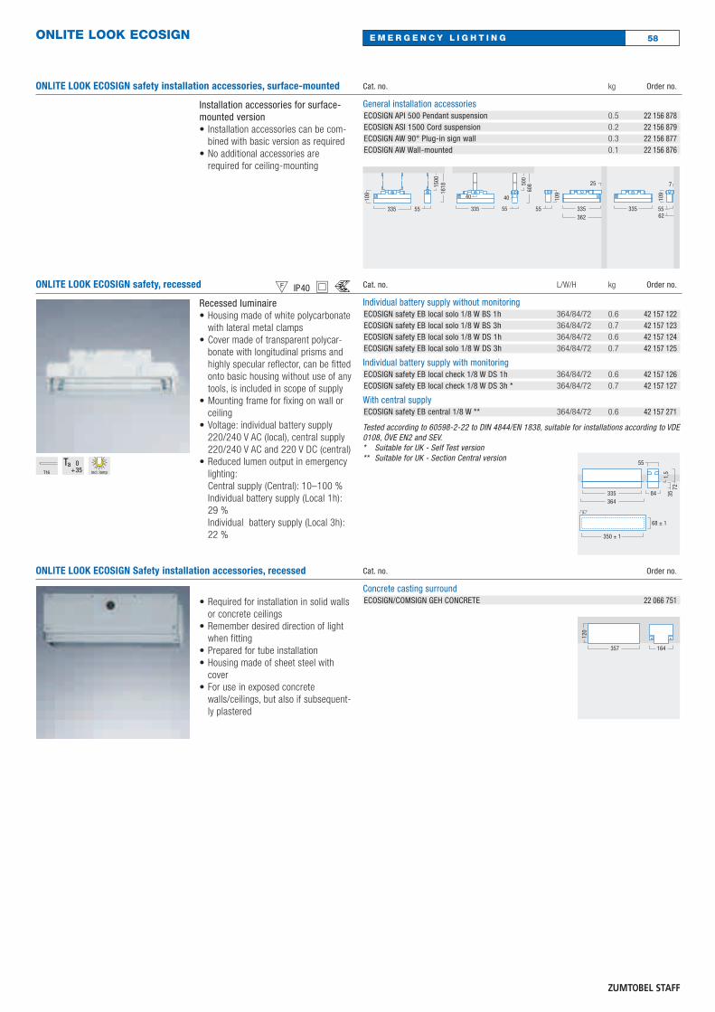
58E M E R G E N C Y L I G H T I N GONLITE LOOK ECOSIGN
ONLITE LOOK ECOSIGN safety installation accessories, surface-mounted
Installation accessories for surface-mounted version• Installation accessories can be com-
bined with basic version as required• No additional accessories are
required for ceiling-mounting
Cat. no. kg Order no.
General installation accessoriesECOSIGN API 500 Pendant suspension 0.5 22 156 878ECOSIGN ASI 1500 Cord suspension 0.2 22 156 879ECOSIGN AW 90° Plug-in sign wall 0.3 22 156 877ECOSIGN AW Wall-mounted 0.1 22 156 876
55
109
335
25
362335
1618
55
1500
335
40
608
55
500
40
7
55
109
62335
109
ONLITE LOOK ECOSIGN safety, recessed chwsRecessed luminaire• Housing made of white polycarbonate
with lateral metal clamps• Cover made of transparent polycar-
bonate with longitudinal prisms andhighly specular reflector, can be fittedonto basic housing without use of anytools, is included in scope of supply
• Mounting frame for fixing on wall orceiling
• Voltage: individual battery supply220/240 V AC (local), central supply220/240 V AC and 220 V DC (central)
• Reduced lumen output in emergencylighting:Central supply (Central): 10–100 %Individual battery supply (Local 1h):29 % Individual battery supply (Local 3h):22 %
Cat. no. L/W/H kg Order no.
Individual battery supply without monitoringECOSIGN safety EB local solo 1/8 W BS 1h 364/84/72 0.6 42 157 122ECOSIGN safety EB local solo 1/8 W BS 3h 364/84/72 0.7 42 157 123ECOSIGN safety EB local solo 1/8 W DS 1h 364/84/72 0.6 42 157 124ECOSIGN safety EB local solo 1/8 W DS 3h 364/84/72 0.7 42 157 125
Individual battery supply with monitoringECOSIGN safety EB local check 1/8 W DS 1h 364/84/72 0.6 42 157 126ECOSIGN safety EB local check 1/8 W DS 3h * 364/84/72 0.7 42 157 127
With central supplyECOSIGN safety EB central 1/8 W ** 364/84/72 0.6 42 157 271
Tested according to 60598-2-22 to DIN 4844/EN 1838, suitable for installations according to VDE0108, ÖVE EN2 and SEV.* Suitable for UK - Self Test version** Suitable for UK - Section Central version
364335 84
55
350 ± 1
68 ± 1
7235
1,5T16 incl. lamp
ONLITE LOOK ECOSIGN Safety installation accessories, recessed
• Required for installation in solid wallsor concrete ceilings
• Remember desired direction of lightwhen fitting
• Prepared for tube installation• Housing made of sheet steel with
cover• For use in exposed concrete
walls/ceilings, but also if subsequent-ly plastered
Cat. no. Order no.
Concrete casting surroundECOSIGN/COMSIGN GEH CONCRETE 22 066 751
357 164
120

ONLITE LOCAL CHECK
ONLITE LOCAL CHECK CONTROLLER
Controller• Controller for 128 luminaires/local
check version• Can be extended to up to 256
luminaires:Circuit1: 64 luminaires Circuit2:Extender I 64 luminaires,Extender II 64 luminaires,Extender III 64 luminaires
• Lamp or battery faults centrally recorded in internal logbook
• Status of complete installation can bedetermined over a period of 2 years
• Dates of weekly function test andannual system test can be set individually
• Programming and display via touchpanel
• 3 individually programmable,potential-free fault report contacts
• Max. cable length to luminaire: 300 m• Integrated power supply for commu-
nication line
Cat. no. Order no.
SB 128 local check Controller 22 156 829
108
130
138
155 65
ONLITE LOCAL CHECK EXTENDER
Extender• Extension module for one channel of
the SB 128 local check CTP• 3 extender modules with a max. of
64 luminaires per extender can beconnected (max. number of lumi-naires: 256)
• Max. cable length to extender: 300 m,from extender to luminaire: 300 m
• Bus supply integrated in module• Switch-cabinet module
Cat. no. L/W/H Order no.
SB 64 local check Extender 35/90/59 22 156 830
90 35
35 59
SB local check GSM-Modul
SB 128 local check controller
RS232 (max. 3 m)
3rd
FLOOR
2nd
FLOOR
1st
FLOOR
GROUNDFLOOR
EB-Extender
EB-Extender
EB-Extender
64Luminaires
64Luminaires
64Luminaires
64Luminaires
(furthest luminaire300 m away
59E M E R G E N C Y L I G H T I N G
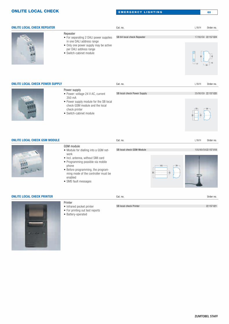
60E M E R G E N C Y L I G H T I N GONLITE LOCAL CHECK
ONLITE LOCAL CHECK REPEATER
Repeater• For separating 2 DALI power supplies
in one DALI address range• Only one power supply may be active
per DALI address range• Switch-cabinet module
Cat. no. L/W/H Order no.
SB 64 local check Repeater 17/90/58 22 157 024
90
17
45
1058
ONLITE LOCAL CHECK POWER SUPPLY
Power supply• Power: voltage 24 V AC, current
350 mA• Power supply module for the SB local
check GSM module and the localcheck printer
• Switch-cabinet module
Cat. no. L/W/H Order no.
SB local check Power Supply 35/90/59 22 157 020
90 35
35 59
ONLITE LOCAL CHECK GSM MODULE
GSM module• Module for dialling into a GSM net-
work• Incl. antenna, without SIM card• Programming possible via mobile
phone• Before programming, the program-
ming mode of the controller must beenabled
• SMS fault messages
Cat. no. L/W/H Order no.
SB local check GSM-Module 105/90/59 22 157 01890 35
105 59
ONLITE LOCAL CHECK PRINTER
Printer• Infrared pocket printer• For printing out test reports• Battery-operated
Cat. no. Order no.
SB local check Printer 22 157 021
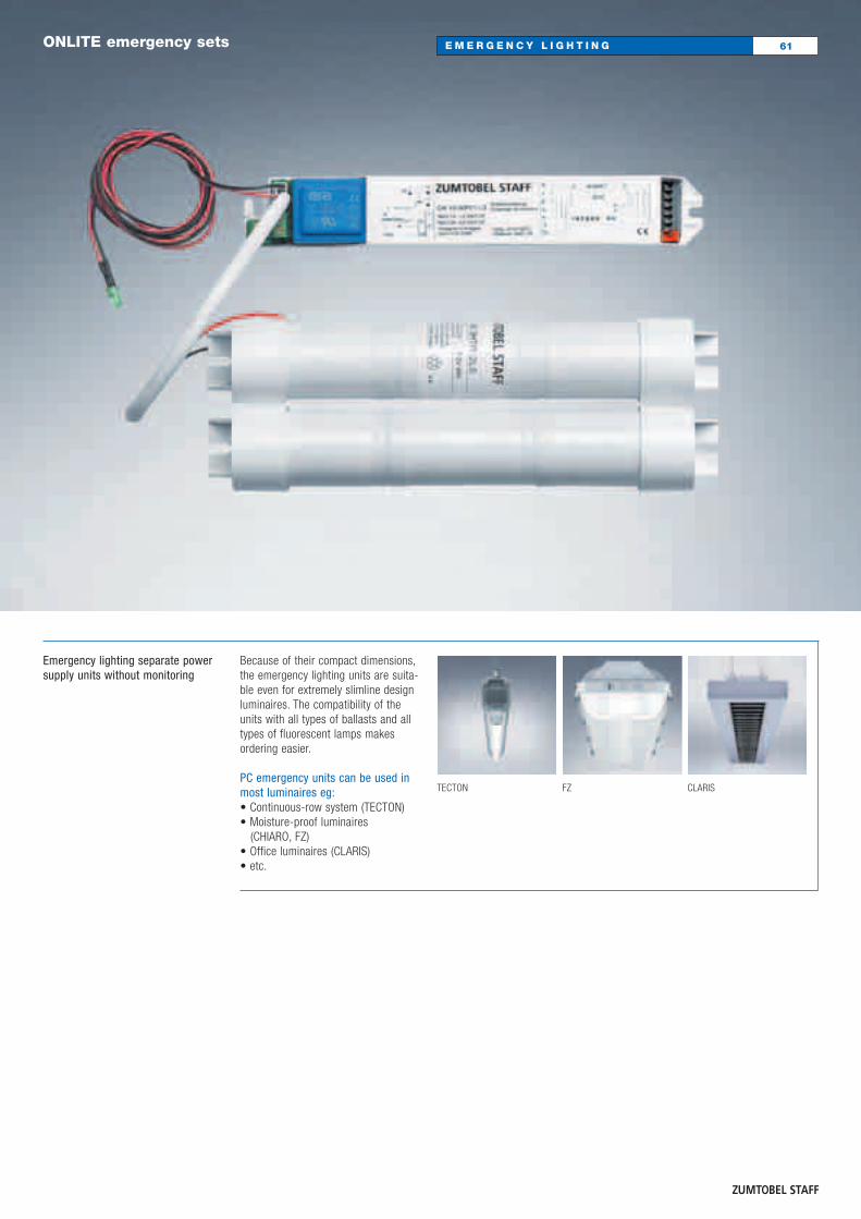
Because of their compact dimensions,the emergency lighting units are suita-ble even for extremely slimline designluminaires. The compatibility of theunits with all types of ballasts and alltypes of fluorescent lamps makes ordering easier.
PC emergency units can be used inmost luminaires eg:• Continuous-row system (TECTON)• Moisture-proof luminaires
(CHIARO, FZ)• Office luminaires (CLARIS)• etc.
TECTON FZ CLARIS
Emergency lighting separate powersupply units without monitoring
61E M E R G E N C Y L I G H T I N GONLITE emergency sets

ONLITE Emergency Set
Emergency Set• Optimum start for T5 lamps• Mains delay switching of ballast• Suitable for all h.f. electronic ballasts
and conventional ballasts• Small dimension• Deep-discharge protection with
reclosing interlock• Maintenance-free, high-temperature
NiCD battery set• Ambient temperature: on emergency
lighting unit: –5 °C up to +60 °C; on battery: 0 °C up to +50 °C
• Voltage: 220–240 V (± 10 %)/ 50/60 Hz
Cat. no. Order no.
Luminaire mounting kitEMERGENCY SET NF1 emergency lighting 1h 22 157 537EMERGENCY SET NF3 emergency lighting 3h 22 157 536
Ballast
NL1L1’
PE122122
NL1L1’
122122
876543
CN 18-65R/1-LS
Emer
genc
y La
mp
PE
NL1L1’
122122
876543
Emer
genc
y La
mp
CN 18-65R/1-LSPE
NL1L1’
122122
876543
Emer
genc
y La
mp
CN 18-65R/1-LS
87
21
TRIDONIC PC-C001/E011
PE
NL1L1’
122122
876543
654321
TRIDONIC PC-E011
CN 18-65R/1-LSPE
Emer
genc
y La
mp
NL1
122122
876543
Emer
genc
y La
mp
CN 18-65R/1-LS
12345678
161514131211109
TRIDONIC PCA Excel one 4 all
PE
L1’
Connecting batteries
Tandem circuit
Switched maintained light
Electronicballasts
Electronicballasts
Electronicballasts
Symbol Lamp Power
W h* %**
T16 21 1–3 25
T16 24 1–3 25
T16 28 1–3 20
T16 35 1–3 20
T16 49 1–3 15
T16 54 1–3 15
T16 80 1–3 10
T26 36 1–3 20
T26 58 1–3 15
TCT 42 1–3 15
* h = hours of emergency operation** % = emergency light flux
62E M E R G E N C Y L I G H T I N GONLITE emergency sets
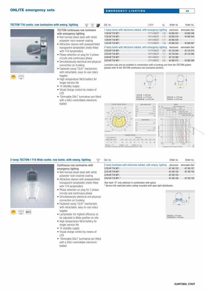
63E M E R G E N C Y L I G H T I N GONLITE emergency sets
TECTON T16 contin. row luminaires with emerg. lighting UceTECTON continuous row luminairewith emergency lighting• Roll-formed sheet steel with white
polyester resin enamel coating• Attractive closure with preassembled
transparent lampholder shells fittedwith T16 lampholders
• Phase selection on plug for 3 phasecircuits and continuous phase
• Simultaneously electrical and physicalconnection on trunking
• Fastened using “CLIX” mechanism,with retractable, easy-to-use rotarytoggles
• High-temperature NiCd battery forlonger service life
• 1h standby supply• Visual charge control by means of
LED• “Dimmable DALI” luminaires are fitted
with a DALI-controllable electronicballast
Cat. no. L/W/H kg Order no. Order no.
1-lamp lumin.with electronic ballast, with emergency lighting electronic dimmable Dali1/28 W T16 NF1 1171/49/37 1.6 42 065 501 42 065 5481/35 W T16 NF1 1471/49/37 1.7 42 065 510 42 065 5541/49 W T16 NF1 1471/49/37 1.7 42 065 5261/54 W T16 NF1 1171/49/37 1.6 42 065 532 42 065 567
2-lamp lumin.with electronic ballast, with emergency lighting electronic dimmable Dali2/28 W T16 NF1 1171/49/37 2.6 42 124 349 42 124 3742/35 W T16 NF1 1471/49/37 1.7 42 124 355 42 124 3802/49 W T16 NF1 1471/49/37 1.7 42 124 3682/54 W T16 NF1 1171/49/37 2.6 42 065 573 42 065 589
Luminaire may only be installed in combination with a trunking unit from the TECTON system(please refer to the TECTON continuous row luminaires section).
30
14/24 W : L=572 mm28/54 W : L=1172 mm35/49/80 W : L=1472 mm
99
60
28/54 W : L=1172 mm35/49 W : L=1472 mm
30
60
99
T16
2-lamp TECTON-I T16 Wide contin. row lumin. with emerg. lighting cContinuous row luminaires with emergency lighting• Roll-formed sheet steel with white
polyester resin enamel coating• Attractive closure with preassembled
transparent lampholder shells fittedwith T16 lampholders
• Phase selection on plug for 3 phasecircuits and continuous phase
• Simultaneously electrical and physicalconnection on trunking
• Fastened using “CLIX” mechanism,with retractable, easy-to-use rotarytoggles
• Lampholder for highest efficency tobe adjusted to Wide position on site
• High-temperature NiCd battery forlonger service life
• 1h standby supply• Visual charge control by means of
LED• “Dimmable DALI” luminaires are fitted
with a DALI-controllable electronicballast
Cat. no. Order no. Order no.
2-lamp luminaire with electronic ballast, with emerg. lighting electronic dimmable Dali2/28 W T16 NF1 42 160 153 42 160 1572/35 W T16 NF1 42 160 154 42 160 1582/49 W T16 NF1 42 160 1552/54 W T16 NF1 * 42 160 156 42 160 159
Test mark “D” only obtained in combination with optics.* Service life restricted when ceiling-mounted with open light distribution.
28/54 W: L=1172 mm35/49/80 W: L=1472 mm
25
103
94
T16850 °C
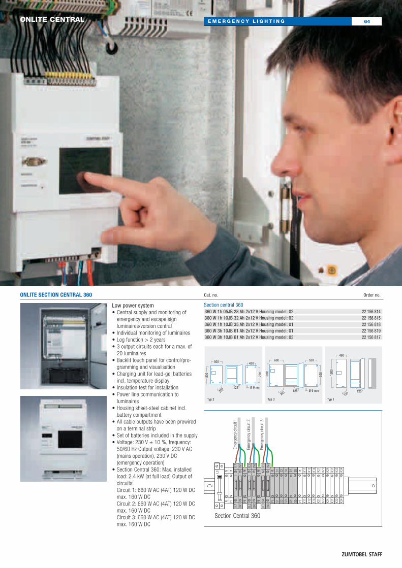
64E M E R G E N C Y L I G H T I N GONLITE CENTRAL
ONLITE SECTION CENTRAL 360
Low power system• Central supply and monitoring of
emergency and escape sign luminaires/version central
• Individual monitoring of luminaires• Log function > 2 years• 3 output circuits each for a max. of
20 luminaires• Backlit touch panel for control/pro-
gramming and visualisation• Charging unit for lead-gel batteries
incl. temperature display• Insulation test for installation• Power line communication to
luminaires• Housing sheet-steel cabinet incl.
battery compartment• All cable outputs have been prewired
on a terminal strip• Set of batteries included in the supply• Voltage: 230 V ± 10 %, frequency:
50/60 Hz Output voltage: 230 V AC(mains operation), 230 V DC (emergency operation)
• Section Central 360: Max. installedload: 2.4 kW (at full load) Output ofcircuits:Circuit 1: 660 W AC (4AT) 120 W DCmax. 160 W DC Circuit 2: 660 W AC (4AT) 120 W DCmax. 160 W DC Circuit 3: 660 W AC (4AT) 120 W DCmax. 160 W DC
Cat. no. Order no.
Section central 360360 W 1h 05JB 28 Ah 2x12 V Housing model: 02 22 156 814360 W 1h 10JB 32 Ah 2x12 V Housing model: 02 22 156 815360 W 1h 10JB 35 Ah 2x12 V Housing model: 01 22 156 818360 W 3h 10JB 61 Ah 2x12 V Housing model: 01 22 156 819360 W 3h 10JB 61 Ah 2x12 V Housing model: 03 22 156 817
500
800
420
720
125°
Typ 2
Ø 9 mm202
600
1000
520
920
125°
Typ 3
Ø 9 mm202
460
1260
125°
Typ 1130
Section Central 360
Emer
genc
y ci
rcui
t 1
Emer
genc
y ci
rcui
t 2
Emer
genc
y ci
rcui
t 3
LS
NN
PEPE
PEPE
PEPE
EL1
EL1
EN1
EN1
EL2
EL2
EN2
EN2
EL3
EL3
EN3
EN3
PEPE
PEPE
K11
K11
K12
K12
K14
K14
K21
K21
K31
K31
K32
K32
K34
K34
K22
K22
K24
K24
S1S1
S2S2
S3S3
S4S4
S5S5
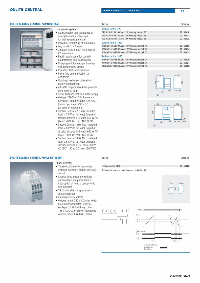
ONLITE CENTRAL
ONLITE SECTION CENTRAL 720/1080/1440
Low power system• Central supply and monitoring of
emergency and escape sign luminaires/version central
• Individual monitoring of luminaires• Log function > 2 years• 3 output circuits each for a max. of
20 luminaires• Backlit touch panel for control/
programming and visualisation• Charging unit for lead-gel batteries
incl. temperature display• Insulation test for installation• Power line communication to
luminaires• Housing sheet-steel cabinet incl.
battery compartment• All cable outputs have been prewired
on a terminal strip• Set of batteries included in the supply• Voltage: 230 V ±10 %, frequency:
50/60 Hz Output voltage: 230 V AC(mains operation), 230 V DC (emergency operation)
• Section Central 720: Max. installedload: 4.7 kW (at full load) Output ofcircuits: circuits 1–6: each 660 W AC(4AT) 120 W DC max. 160 W DC
• Section Central 1080: Max. installedload: 7.0 kW (at full load) Output ofcircuits: circuits 1–9: each 660 W AC(4AT) 120 W DC max. 160 W DC
• Section Central 1440: Max. installedload: 9.5 kW (at full load) Output ofcircuits: circuits 1–12: each 660 WAC (4AT) 120 W DC max. 160 W DC
Cat. no. Order no.
Section central 720720 W 1h 05JB 28 Ah 4x12 V Housing model: 03 22 156 820720 W 1h 10JB 32 Ah 4x12 V Housing model: 03 22 156 821720 W 3h 10JB 61 Ah 4x12 V Housing model: 03 22 156 822
Section central 10801080 W 1h 05JB 28 Ah 6x12 V Housing model: 04 22 156 8231080 W 1h 10JB 32 Ah 6x12 V Housing model: 04 22 156 8241080 W 3h 10JB 61 Ah 6x12 V Housing model: 04 22 156 825
Section central 14401440 W 1h 05JB 28 Ah 8x12 V Housing model: 04 22 156 8261440 W 1h 10JB 32 Ah 8x12 V Housing model: 04 22 156 8271440 W 3h 10JB 61 Ah 8x12 V Housing model: 04 22 156 828
ONLITE SECTION CENTRAL PHASE DETECTOR
Phase detector• Three-circuit monitoring module
installed in switch cabinet, for fixingon rail
• Checks three-phase network forundervoltage and phase failure; interruption of neutral conductor isalso detected
• 3 LEDs for status display (mains voltage applied)
• 2 change-over contacts• Voltage range: 230 V AC, max. volta-
ge of outer conductor: 450 V ACWattage: 15 W Switching contact:125 V AC/DC, 2A (60 W) Monitoringwindow: Unetz 0.6–0.85 Unenn
Cat. no. Order no.
Section central EPD 22 156 808
Suitable for use in installations acc. to VDE 0108.90 35
35 59
N L1 L2 L3 1 2 1 2
3 4 3 4
U NENN
Us
Mains
Make contacts2 - 41 - 3
1 - 32 - 4
t
T=switching delay us
< t< t
Us
Contact closedContact open
600
1000
520
920
125°
Typ 3
Ø 9 mm202
900
1590
720
1480
125°
Typ 4
Ø 9 mm 30 mm
40
202
65E M E R G E N C Y L I G H T I N G

66E M E R G E N C Y L I G H T I N GONLITE CENTRAL
ONLITE SECTION CENTRAL POWER SUPPLY
Power supply• Power: voltage 24 V AC,
current 350 mA• Power supply module for the SB local
check GSM module and the localcheck printer
• Switch-cabinet module
Cat. no. Order no.
Section central Power Supply 22 156 809
90 35
35 59
ONLITE SECTION CENTRAL GSM MODULE
GSM module• Module for dialling into a GSM net-
work• Incl. antenna, without SIM card• Programming possible via mobile
phone• Before programming, the program-
ming mode of the controller must beenabled
• SMS fault messages
Cat. no. Order no.
Section central GSM 22 156 810
90 35
105 59
ONLITE SECTION CENTRAL PRINTER
Printer• Microprinter for switch-cabinet
installation• Printing speed 60 mm/sec, RS 232
interface• Low-noise• For printing out test reports
Cat. no. Order no.
Section central Printer 22 156 812
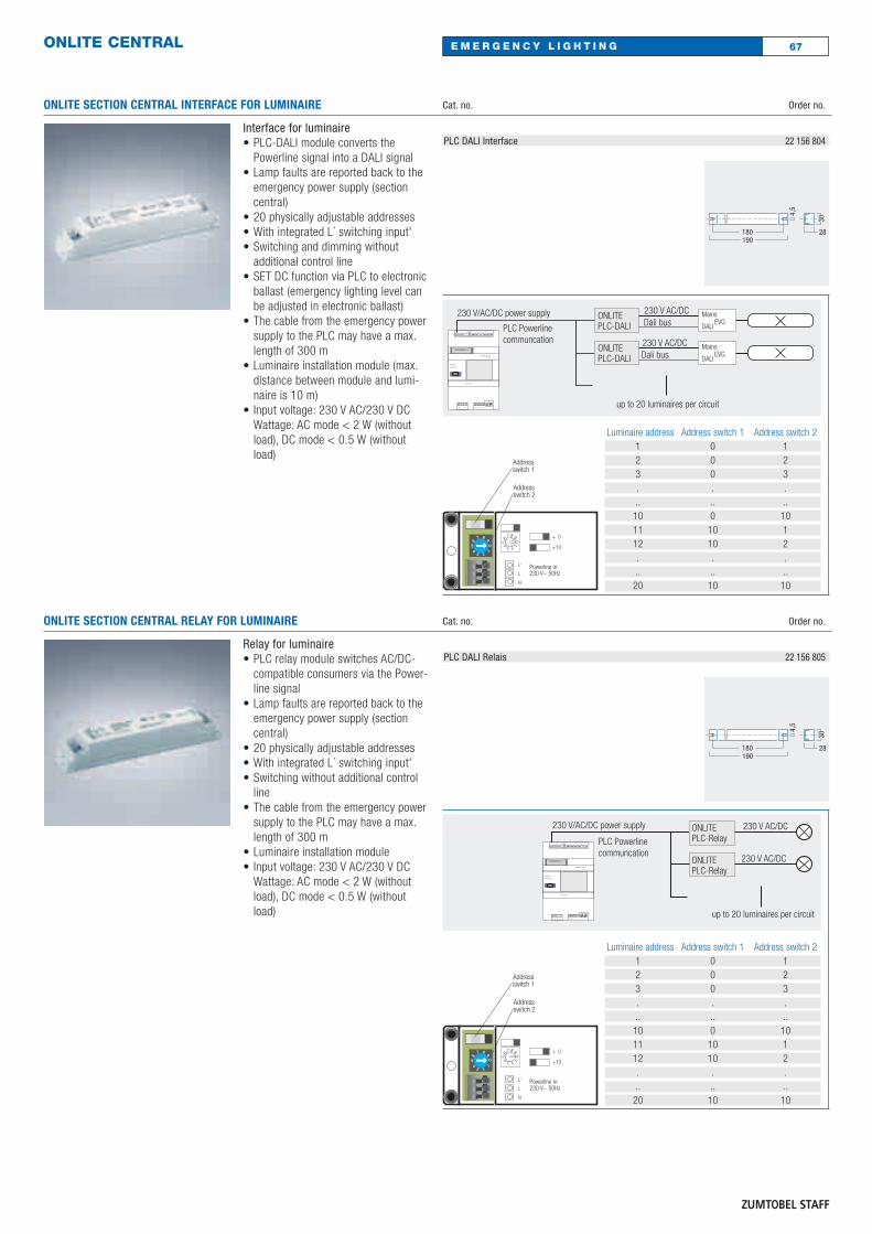
ONLITE CENTRAL
Interface for luminaire• PLC-DALI module converts the
Powerline signal into a DALI signal• Lamp faults are reported back to the
emergency power supply (sectioncentral)
• 20 physically adjustable addresses• With integrated L´ switching input'• Switching and dimming without
additional control line• SET DC function via PLC to electronic
ballast (emergency lighting level canbe adjusted in electronic ballast)
• The cable from the emergency powersupply to the PLC may have a max.length of 300 m
• Luminaire installation module (max.distance between module and lumi-naire is 10 m)
• Input voltage: 230 V AC/230 V DCWattage: AC mode < 2 W (withoutload), DC mode < 0.5 W (withoutload)
Cat. no. Order no.
PLC DALI Interface 22 156 804
180190
28
30
4,5
Luminaire address Address switch 1 Address switch 21 0 12 0 23 0 3. . ... .. ..10 0 1011 10 112 10 2. . ... .. ..20 10 10
Addressswitch 1
Addressswitch 2
0
2
67
134
5
89
+ 0
+10
Powerline inL'
L
N
01234567
89
230 V~ 50Hz
ONLITEPLC-DALI Dali bus
up to 20 luminaires per circuit
ONLITEPLC-DALI
Mains/Netz
Failure/Stˆrung
ZUMTOBEL STAFFDAS LICHT
SEPS 360
Æ
Fuse / Sicherung
L NPE
O3O2 U3U2O1U1
S1 S2 D1 D2Rx GndTx +_
12 14T1
11T3 P1 P2
Relais 122 2421
Relais 232 3431
Relais 3T2
230 V/AC/DC power supply
PLC Powerline communcation
230 V AC/DC
Dali bus230 V AC/DC
EVG DALI
Mains
EVG DALI
Mains
ONLITE SECTION CENTRAL RELAY FOR LUMINAIRE
Relay for luminaire• PLC relay module switches AC/DC-
compatible consumers via the Power-line signal
• Lamp faults are reported back to theemergency power supply (sectioncentral)
• 20 physically adjustable addresses• With integrated L´ switching input'• Switching without additional control
line• The cable from the emergency power
supply to the PLC may have a max.length of 300 m
• Luminaire installation module• Input voltage: 230 V AC/230 V DC
Wattage: AC mode < 2 W (withoutload), DC mode < 0.5 W (withoutload)
Cat. no. Order no.
PLC DALI Relais 22 156 805
180190
28
30
4,5
Luminaire address Address switch 1 Address switch 21 0 12 0 23 0 3. . ... .. ..10 0 1011 10 112 10 2. . ... .. ..20 10 10
Addressswitch 1
Addressswitch 2
0
2
67
134
5
89
+ 0
+10
Powerline inL'
L
N
01234567
89
230 V~ 50Hz
Mains/Netz
Failure/Stˆrung
ZUMTOBEL STAFFDAS LICHT
SEPS 360
Æ
Fuse / Sicherung
L NPE
O3O2 U3U2O1U1
S1 S2 D1 D2Rx GndTx +_
12 14T1
11T3 P1 P2
Relais 122 2421
Relais 232 3431
Relais 3T2
230 V/AC/DC power supply
PLC Powerline communcation
230 V AC/DC
230 V AC/DC
up to 20 luminaires per circuit
ONLITEPLC-Relay
ONLITEPLC-Relay
67
ONLITE SECTION CENTRAL INTERFACE FOR LUMINAIRE
E M E R G E N C Y L I G H T I N G
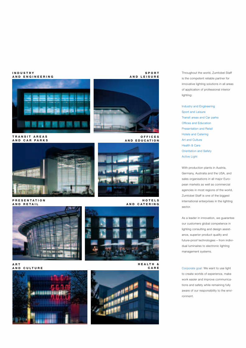
Throughout the world, Zumtobel Staff
is the competent reliable partner for
innovative lighting solutions in all areas
of application of professional interior
lighting:
Industry and Engineering
Sport and Leisure
Transit areas and Car parks
Offices and Education
Presentation and Retail
Hotels and Catering
Art and Culture
Health & Care
Orientation and Safety
Active Light
With production plants in Austria,
Germany, Australia and the USA, and
sales organisations in all major Euro-
pean markets as well as commercial
agencies in most regions of the world,
Zumtobel Staff is one of the biggest
international enterprises in the lighting
sector.
As a leader in innovation, we guarantee
our customers global competence in
lighting consulting and design assist-
ance, superior product quality and
future-proof technologies – from indivi-
dual luminaires to electronic lighting
management systems.
Corporate goal: We want to use light
to create worlds of experience, make
work easier and improve communica-
tions and safety while remaining fully
aware of our responsibility to the envi-
ronment.
P R E S E N T A T I O NA N D R E T A I L
A R T A N D C U L T U R E
H O T E L S A N D C A T E R I N G
S P O R T A N D L E I S U R E
H E A L T H & C A R E
T R A N S I T A R E A SA N D C A R P A R K S
O F F I C E S A N D E D U C A T I O N
I N D U S T R Y A N D E N G I N E E R I N G
United Kingdom
Zumtobel Staff Lighting Ltd.
Unit 4 - The Argent Centre,
Pump Lane
Hayes/Middlesex UB3 3BL
Tel. +44/(0)20 8589 1800
Fax +44/(0)20 8756 4800
Email: [email protected]
USA and Canada
Zumtobel Staff Lighting
3300 Route 9W
Highland, New York 12528
Tel. +1/(0)845/691 62 62
Fax +1/(0)845/691 62 89
www.zumtobelstaffusa.com
Australia and New Zealand
Zumtobel Staff (Australia) Pty. Ltd.
2 Wella Way
Somersby, NSW 2250
Tel. +61/(2)4340 3200
Fax +61/(2)4340 2108
Email: [email protected]
Norway
Zumtobel Staff Jakobsson
Industriveien 11
1483 Skytta
Tel: +47/(0)67 06 22 30
Fax: +47/(0)67 06 22 69
Email: [email protected]
Sweden
Zumtobel Staff Jakobsson AB
Besöksadress: Norr Mälarstrand 8
Postadress: Box 22318
104 22 Stockholm
Tel: +46/(0)8 26 26 50
Fax: +46/(0)8-26 56 05
E-mail: [email protected]
www.zumtobelstaffjakobsson.se
Art.-No. 04 797 359-UK 03/04 © Zumtobel StaffTechnical data was correct at time of going to press. We reserve the right to make technical changes without notice. Please contact your local sales office for further information. Printed on environmentally-friendly chlorine-free paper. Printed on Consort Royal.
Head offices
Zumtobel Staff GmbH
Schweizer Strasse 30
Postfach 72
A-6851 Dornbirn, AUSTRIA
Tel. +43/(0)5572/390-0
Fax +43/(0)5572/22 826
Zumtobel Staff GmbH & Co. KG
Grevenmarschstr. 74-78
D-32657 Lemgo, GERMANY
Tel. +49/(0)5261/2 12-0
Fax +49/(0)5261/2 12-7777
www.zumtobelstaff.de
www.zumtobelstaff.com
Track and spots
Modular lighting systems
Down-/uplights
Recessed luminaires
Surface-mounted and pendant luminaires
Wallwashers
LED, task, wall and uplights
Continuous row and batten luminaires
High-bay luminaires
Luminaires with extra protection
Lighting Controls
Emergency lighting
Medical supply systems
Dokument 2 17.03.2004 16:37 Uhr Seite 5