(only 200 l type) digital flow switch rohs
TRANSCRIPT

Applicable fluid Dry air, N2
2-Colour Display
Compared with thePFMB7201 andPF2A721-03
Compared with thePFMB7501-04 andPF2A751-04
30
45.2
1 20.2 0.5 5 10 20 25 50 100 150 200 300 500 600 1000 2000Rated flow range [l/min]
2 200
5 500
10 1000
18
34
44
73
100 :1100 :1∗1 Rated flow ratio is 10 : 1 for the current PF2A.
Smallest settable increment: 1 l/minCurrent PF2A: 5 l/min (200 L: 2 l/min)
Wide range of flow measurementwith one product
Flow ratio∗1
500 L/1000 L/
2000 L type200 L type
Compact, Space saving
∗∗11111 RaRatRatRatRateded d
FFFllooowwww SSmmmaallllCuCuCurrrrene t PP
70116
34
73
20 2000
Compared with the current PF2A
Compared with the current PF2A
Approx. 76 %reduction
Approx. 81 %reduction
Approx. 66 %reduction
Approx. 67 %reduction
WeightMountingspace
WeightMountingspace
290 g a 70 g
290 g a 100 g
29 mm
shorter 27.8 mm
shorter
4 m
m
shorter
16 m
m
shorter
46 mm shorter
PF2A series
(Current model)PF2A series
(Current model)
PFMBPFMB
7011646 mm shorter
PFG300 Series
NewNew
Digital Flow MonitorAllows for the monitoring ofremote lines
3-Screen Display
p. 24
CAT.EUS100-95C-UK
PFMB Series
®
RoHS
(Only 200 L type)
Digital Flow Switch
Protruding part
Moist air
Sensor unit
PFMB Series
With a reversible display function
(Can be set with the reversible display mode.)
When display is upside down.
500 L/1000 L/2000 L type
OUT IN OUT IN
OUT IN OUT IN
S
IN
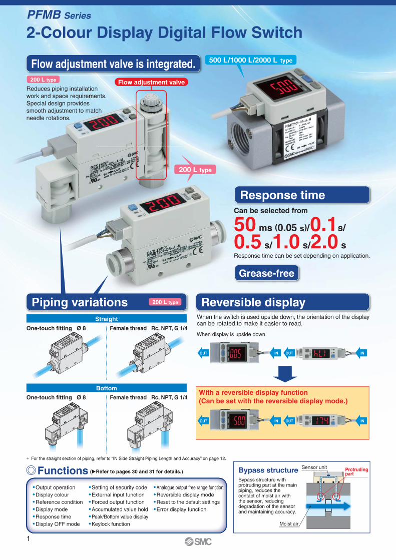
∗ For the straight section of piping, refer to “IN Side Straight Piping Length and Accuracy” on page 12.
Can be selected from
50 ms (0.05 s)/ 0.1s/
0.5 s/1.0 s/2.0 sResponse time can be set depending on application.
Flow adjustment valve
Flow adjustment valve is integrated.
2-Colour Display Digital Flow Switch
Response time
Functions Bypass structure
� Output operation� Display colour� Reference condition� Display mode� Response time� Display OFF mode
� Setting of security code� External input function� Forced output function� Accumulated value hold� Peak/Bottom value display� Keylock function
� Analogue output free range function� Reversible display mode� Reset to the default settings� Error display function
(�Refer to pages 30 and 31 for details.)
Bypass structure with protruding part at the main piping, reduces the contact of moist air with the sensor, reducing degradation of the sensor and maintaining accuracy.
200 L type
Grease-free
Reduces piping installation
work and space requirements.
Special design provides
smooth adjustment to match
needle rotations.
Piping variations Reversible display
Straight
Bottom
One-touch fitting Ø 8 Female thread Rc, NPT, G 1/4
One-touch fitting Ø 8 Female thread Rc, NPT, G 1/4
200 L type
When the switch is used upside down, the orientation of the display can be rotated to make it easier to read.
200 L type
1
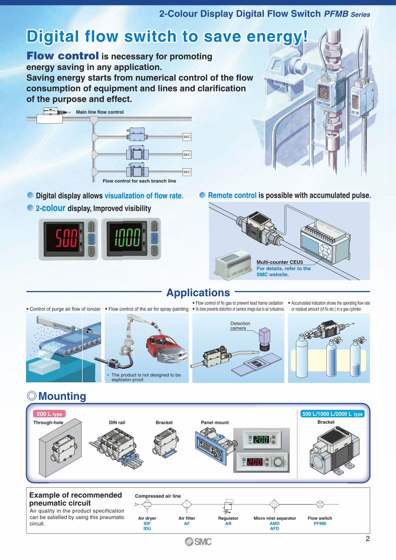
BracketDIN railThrough-hole Panel mount Bracket
M/C
M/C
M/C
Main line flow control
Flow control for each branch line
Multi-counter CEU5
For details, refer to the
SMC website.
Digital flow switch to save energy!Digital flow switch to save energy!
� Control of purge air flow of ionizer � Flow control of the air for spray painting
� Flow control of N2 gas to prevent lead frame oxidation� N2 blow prevents distortion of camera image due to air turbulence.
� Accumulated indication shows the operating flow rate
or residual amount (of N2 etc.) in a gas cylinder.
Digital display allows visualization of flow rate.
2-colour display, Improved visibility
Remote control is possible with accumulated pulse.
Applications
Detectioncamera
2-Colour Display Digital Flow Switch PFMB Series
Air dryer
IDFIDU
AF AR AMDAFD
PFMB
Air filter Regulator Micro mist separator Flow switch
200 L type 500 L/1000 L/2000 L type
Compressed air lineExample of recommended pneumatic circuit
Mounting
Air quality in the product specification
can be satisfied by using this pneumatic
circuit.
Flow control is necessary for promoting
energy saving in any application.
Saving energy starts from numerical control of the flow
consumption of equipment and lines and clarification
of the purpose and effect.
ionizer Flow control of the air for spray painting
∗ The product is not designed to beexplosion proof.
2
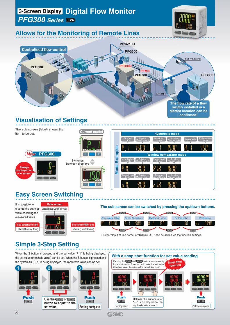
The sub screen (label) shows the
item to be set.
It is possible to
change the settings
while checking the
measured value.
When the S button is pressed and the set value (P_1) is being displayed,
the set value (threshold value) can be set. When the S button is pressed and
the hysteresis (H_1) is being displayed, the hysteresis value can be set.
Current model
PFG300NewNewNewSwitches
between displays
Normal output/Lo side
Set value (Threshold value)
Normal output/Hi side
Set value (Threshold value)
1 2 3
Push Push
Setting complete
Use the or button to adjust to the set value.
∗ Either “Input of line name” or “Display OFF” can be added via the function settings.
The sub screen can be switched by pressing the up/down buttons.
Label (Display item)
Sub screen/Left side
Push Push
Setting completeSetting start
Release the buttons after
“---” is displayed on the
right side sub screen.
Visualisation of Settings
Allows for the Monitoring of Remote Lines
Easy Screen Switching
Simple 3-Step Setting
Pressing the and buttons simultaneously for a minimum of 1 second will make the set value (threshold value) the same as the current fl ow value.
With a snap shot function for set value reading
Snap shot
function
Accumulated fl ow Set value (Threshold value) Hysteresis value Bottom value Peak value
Mo
de E
xam
ple
s
Hysteresis mode
Window comparator mode
Normal output
Set value (Threshold value)
Reversed output
Set value (Threshold value) Hysteresis Set hysteresis
value
Reversed output/Lo side
Set value (Threshold value)
Reversed output/Hi side
Set value (Threshold value)
Measured value (Current flow value)
Main screen
Set value (Threshold value)
Sub screen/Right side
PFG300
PFG300
PF3A7�H
PFMB
PFG300PFG300
PFG300
3-Screen Display Digital Flow MonitorPFG300 Series
Alwaysdisplayed on one screen
Centralised flow control
The flow rate of a flow switch installed in a
distant location can be confirmed!
p. 24
For main line
PFMC
3

Bracket A
Bracket B
Panel mount
Voltage input 1 V 5 VCurrent input 4 mA 20 mA
Display
B
A
Voltage input
Display
1,000
01 V 5 V
�Copy functionThe settings of the
master monitor can
be copied to the slave
monitors.
�Power saving modePower consumption is reduced by turning off the monitor.
�Security code The key locking function
keeps unauthorized persons
from tampering with the
settings.
�External input functionThe accumulated value, peak value, and bottom value can be reset remotely.
Current consumption∗1 Reduction rate∗2
25 mA or less Approx. 50 % reduction
∗1 During normal operation ∗2 In power saving mode
Master
monitor1 unit
Slave side
10 units2 units
C o p yC o p y
6 mm shorter25 mm
�Compact: Max. 6 mm shorter
�Lightweight: Max. 5 g lighter (30 g / 25 g)
PFG300
PFM300
The bracket confi guration allows for mounting in four orientations.
Mountable side by side without clearance
One opening! · Reduced panel fi tting labour
· Space saving
Convenient Functions
Mounting
Compact & Lightweight
31 mm
¡Selection of display on sub screen
¡Analogue output free range function
¡Error display function
¡Copy function
¡Selection of power saving mode
Functions (s Refer to pages 32 to 34 for details.)
¡Output operation
¡Simple setting mode
¡Display colour
¡Delay time setting
¡Digital fi lter setting
¡FUNC output switching function
¡Selectable analogue output function
¡External input function
¡Forced output function
¡Accumulated value hold
¡Peak/Bottom value display
¡Setting of security code
¡Keylock function
¡Reset to the default settings
¡Display with zero cut-off setting
The number of stock items can be reduced. The displayed value to the sensor input can be set as required.
(Voltage input: 1 to 5 V/Current input: 4 to 20 mA)
Pressure switch/Flow switch can be displayed.
A is displayed for 1 V (or 4 mA).
B is displayed for 5 V (or 20 mA).
The range can be set as required.
�Pressure Sensor for General Fluids/PSE570
Set A and B to the values shown in the table above.
A B
PSE570 0 1,000
PSE573 -100 100
PSE574 0 500
Select NPN or PNP
NPN/PNP Switch Function
Analogue output of 0 to 10 V is also available.
Input Range Selection (for Pressure/Flow rate)
NPN PNP
Voltage output1 to 5 V
Switchable0 to 10 V
Current output 4 to 20 mA Fixed
Mounting example
Mounting example
4
Digital Flow Monitor PFG300 Series3-Screen Display
Series
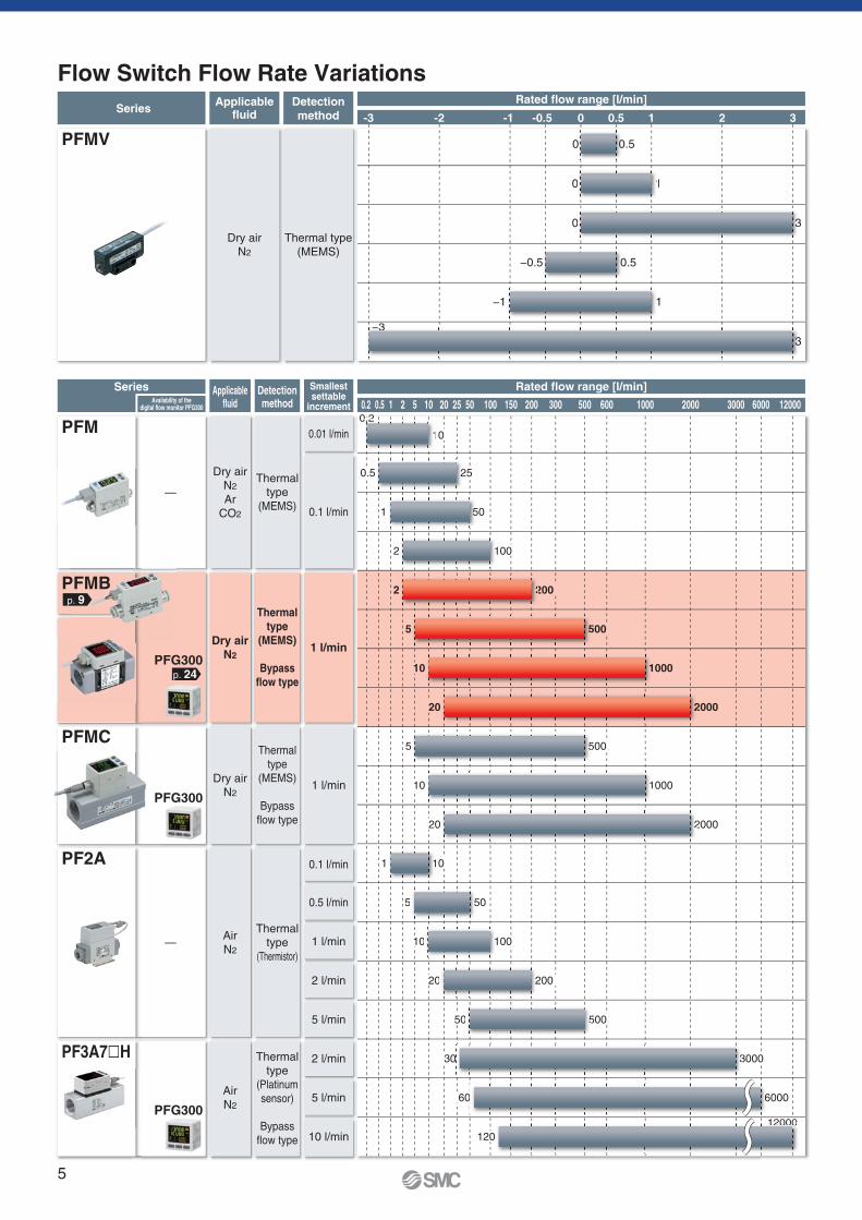
1 20.2 0.5 5 10 20 25 50 100 150 200 300 500 600 1000 2000 3000 6000 12000
Rated flow range [l/min]
0.5 25
1 50
2 100
2 200
5 500
10 1000
1 10
5 50
10 100
20 200
50 500
0.2
10
−0.5 0.5
SeriesDetection
method
Applicablefluid
Smallestsettable
increment
Detectionmethod
Applicablefluid
Thermal type
(MEMS)
Thermal
type
(MEMS)
Dry air
N2
Dry air
N2
Ar
CO2
Dry air
N2
0.1 l/min
0.5 l/min
1 l/min
2 l/min
5 l/min
2 l/min
5 l/min
10 l/min
Thermal
type
(MEMS)
Bypass
flow type
Thermal
type
(Thermistor)
Air
N2
—
—
Thermal
type
(Platinum
sensor)
Bypass
flow type
Air
N2
0.1 l/min
0.01 l/min
1 l/min
Dry air
N2
Thermal
type
(MEMS)
Bypass
flow type
1 l/min
1 2 3-3 -2 -1 -0.5 0 0.5
Rated flow range [l/min]
PFMV
PFM
PFG300
PFG300
PF2A
PF3A7�H
PFMB
PFMC
−1
−3
1
1
1
20 20002
5
5 500
10 10001
20 20002
5
2
1
5
2
0.2.2
1
1
5
2
5
−3
1
5 0
0 10 1
0 3
3
0 3
0 0.50 0
30 3000
60 6000
120
12000
3
6
1200000
Availability of thedigital flow monitor PFG300
PFG300
p. 9
p. 24
Flow Switch Flow Rate Variations
5
Digital
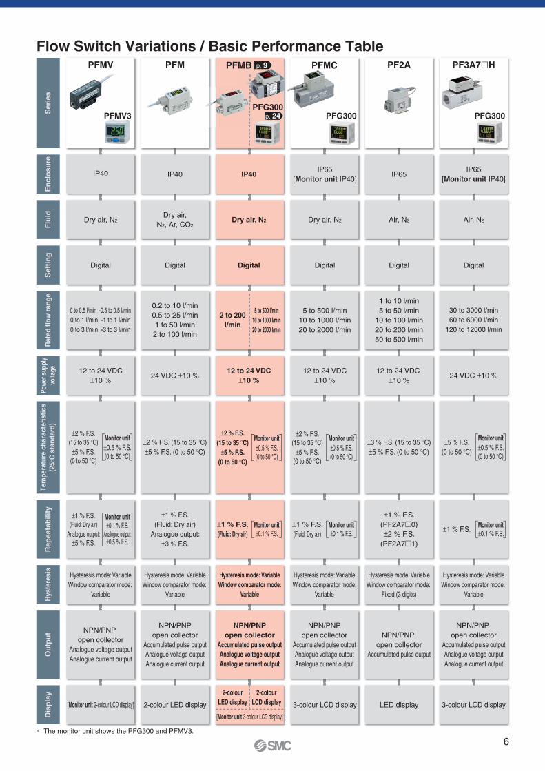
IP40
2-colour
LED display
2-colour
LCD display
NPN/PNP
open collector
Accumulated pulse output
Analogue voltage output
Analogue current output
Hysteresis mode: Variable
Window comparator mode:
Variable
±1 % F.S.
(Fluid: Dry air)
±2 % F.S.
(15 to 35 °C)
±5 % F.S.
(0 to 50 °C)
Dry air, N2
12 to 24 VDC
±10 %
[Monitor unit 3-colour LCD display]
2 to 200
l/min
5 to 500 l/min
10 to 1000 l/min
20 to 2000 l/min
Digital
3-colour LCD display
NPN/PNP
open collector
Accumulated pulse output
Analogue voltage output
Analogue current output
Hysteresis mode: Variable
Window comparator mode:
Variable
±1 % F.S.
(Fluid: Dry air)
±2 % F.S.
(15 to 35 °C)
±5 % F.S.
(0 to 50 °C)
Dry air, N2
IP65
[Monitor unit IP40]
12 to 24 VDC
±10 %
PFMC
5 to 500 l/min
10 to 1000 l/min
20 to 2000 l/min
Monitor unit
±0.1 % F.S.
Monitor unit
±0.5 % F.S.
(0 to 50 °C)
Monitor unit
±0.1 % F.S.
Monitor unit
±0.5 % F.S.
(0 to 50 °C)
PFMB p. 9
p. 24PFG300
PFG300
Flow Switch Variations / Basic Performance Table
∗ The monitor unit shows the PFG300 and PFMV3.
Flu
idS
eri
es
PFM PF2A
Dry air,
N2, Ar, CO2
Sett
ing
Digital Digital
En
clo
su
re
IP40
Dis
pla
y
2-colour LED display
Ou
tpu
t
NPN/PNP
open collector
Accumulated pulse output
Analogue voltage output
Analogue current output
Hy
ste
res
is
Hysteresis mode: Variable
Window comparator mode:
Variable
Hysteresis mode: Variable
Window comparator mode:
Variable
Rep
eata
bilit
y
±1 % F.S.
(Fluid: Dry air)
Analogue output:
±3 % F.S.
±2 % F.S. (15 to 35 °C)
±5 % F.S. (0 to 50 °C)
Pow
er s
uppl
y
volta
ge
24 VDC ±10 %
Ra
ted
flo
w r
an
ge
0.2 to 10 l/min
0.5 to 25 l/min
1 to 50 l/min
2 to 100 l/min
PFMV
Air, N2
IP65
LED display
NPN/PNP
open collector
Accumulated pulse output
Hysteresis mode: Variable
Window comparator mode:
Fixed (3 digits)
±1 % F.S.
(PF2A7�0)
±2 % F.S.
(PF2A7�1)
±3 % F.S. (15 to 35 °C)
±5 % F.S. (0 to 50 °C)
12 to 24 VDC
±10 %
1 to 10 l/min
5 to 50 l/min
10 to 100 l/min
20 to 200 l/min
50 to 500 l/min
Digital
IP40
[Monitor unit 2-colour LCD display]
NPN/PNP
open collector
Analogue voltage output
Analogue current output
±1 % F.S.
(Fluid: Dry air)
Analogue output:
±5 % F.S.
Monitor unit
±0.1 % F.S.Analogue output:
±0.5 % F.S.
±2 % F.S.
(15 to 35 °C)
±5 % F.S.
(0 to 50 °C)
Monitor unit
±0.5 % F.S.
(0 to 50 °C)
12 to 24 VDC
±10 %
0 to 0.5 l/min -0.5 to 0.5 l/min
0 to 1 l/min -1 to 1 l/min
0 to 3 l/min -3 to 3 l/min
Dry air, N2
PF3A7�H
Digital
Air, N2
IP65
[Monitor unit IP40]
3-colour LCD display
NPN/PNP
open collector
Accumulated pulse output
Analogue voltage output
Analogue current output
Hysteresis mode: Variable
Window comparator mode:
Variable
±1 % F.S.
±5 % F.S.
(0 to 50 °C)
24 VDC ±10 %
30 to 3000 l/min
60 to 6000 l/min
120 to 12000 l/min
Monitor unit
±0.1 % F.S.
Monitor unit
±0.5 % F.S.
(0 to 50 °C)
PFMV3 PFG300
Tem
pera
ture
ch
ara
cte
risti
cs
(25
°C s
tan
dard
)
6

7
2-Colour Display Digital Flow Switch PFMB Series
3-Screen Display Digital Flow Monitor PFG300 Series
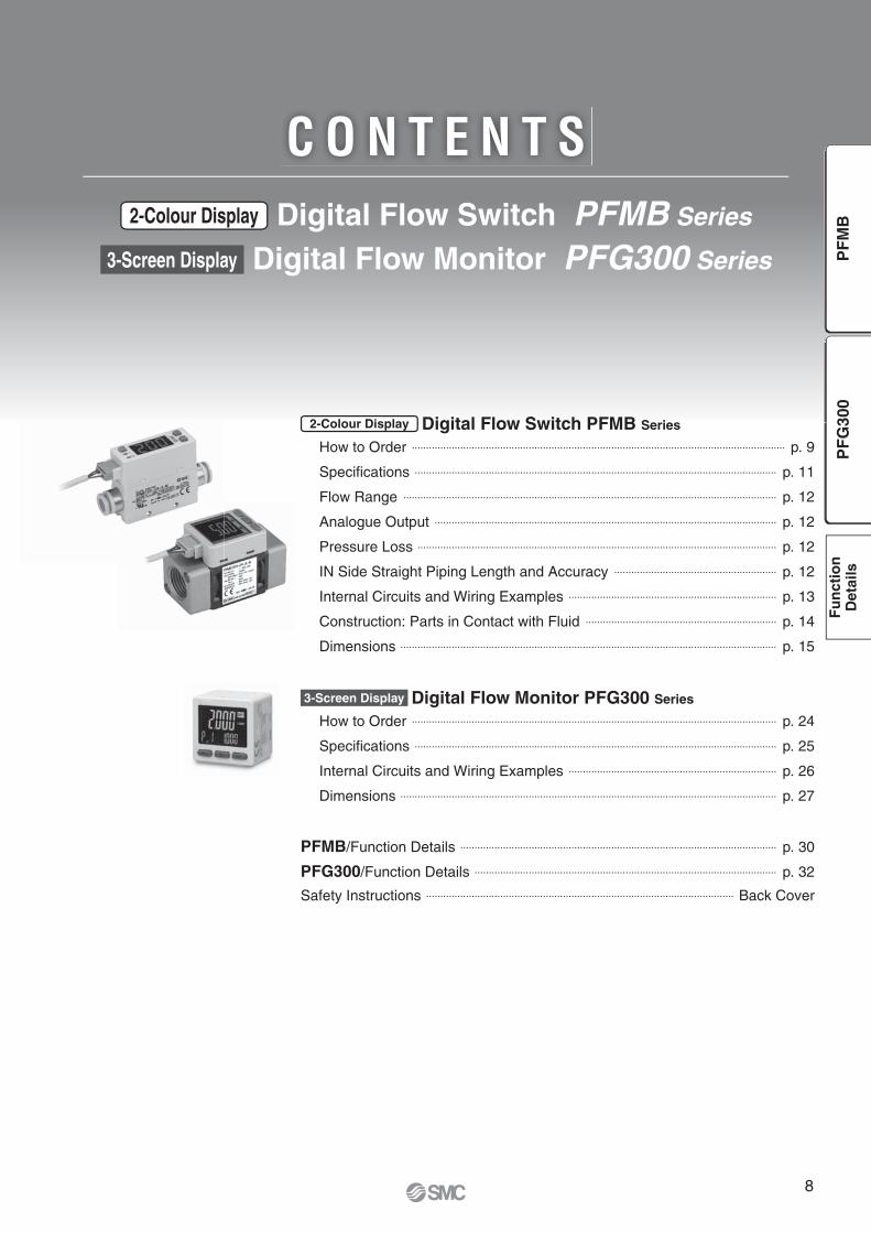
C O N T E N T S
2-Colour Display Digital Flow Switch PFMB Series
How to Order ··································································································································· p. 9
Specifications ······························································································································· p. 11
Flow Range ··································································································································· p. 12
Analogue Output ························································································································ p. 12
Pressure Loss ······························································································································ p. 12
IN Side Straight Piping Length and Accuracy ························································· p. 12
Internal Circuits and Wiring Examples ········································································· p. 13
Construction: Parts in Contact with Fluid ··································································· p. 14
Dimensions ···································································································································· p. 15
3-Screen Display Digital Flow Monitor PFG300 Series
How to Order ································································································································ p. 24
Specifications ······························································································································· p. 25
Internal Circuits and Wiring Examples ········································································· p. 26
Dimensions ···································································································································· p. 27
PFMB/Function Details ··············································································································· p. 30
PFG300/Function Details ·········································································································· p. 32
Safety Instructions ············································································································ Back Cover
8
PF
G3
00
PF
MB
Fu
ncti
on
Deta
ils
®
S
IN
S
IN
S
IN
With 2
tapping
screws
With 3
tapping
screws
Mounting bracket
Panel mount
adapter B
Panel mount
adapter A
Panel
Panel mount
adapter A
Panel
Panel mount
adapter B
Mounting bracket
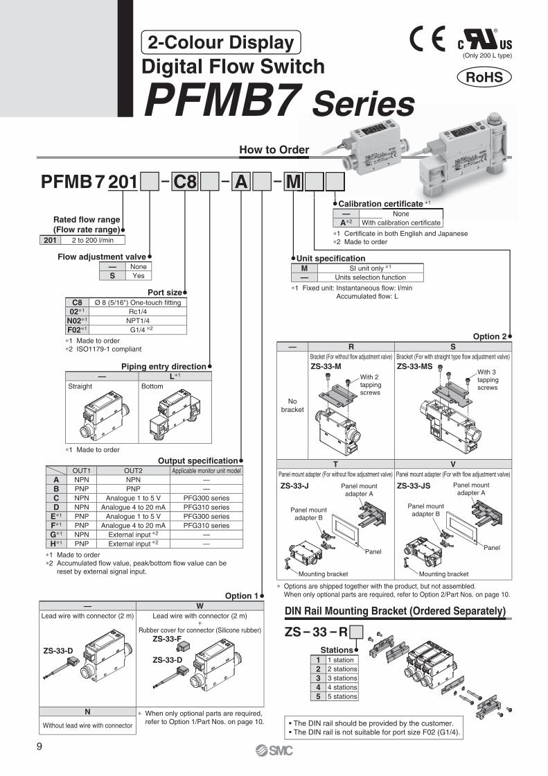
How to Order
PFMB7 201 C8 A
Unit specifi cation
∗1 Fixed unit: Instantaneous fl ow: l/min
Accumulated fl ow: L
∗1 Made to order
∗2 ISO1179-1 compliant
∗1 Made to order
M
Flow adjustment valve
Rated fl ow range
(Flow rate range)
Port size
Piping entry direction
Output specifi cation
∗1 Certifi cate in both English and Japanese
∗2 Made to order
Option 2
∗ Options are shipped together with the product, but not assembled.
When only optional parts are required, refer to Option 2/Part Nos. on page 10.Option 1
ZS 33 R
Stations
• The DIN rail should be provided by the customer.
• The DIN rail is not suitable for port size F02 (G1/4).
DIN Rail Mounting Bracket (Ordered Separately)
RoHS
(Only 200 L type)
∗1 Made to order
∗2 Accumulated fl ow value, peak/bottom fl ow value can be
reset by external signal input.
1 1 station
2 2 stations
3 3 stations
4 4 stations
5 5 stations
— W
Lead wire with connector (2 m) Lead wire with connector (2 m)+
Rubber cover for connector (Silicone rubber)
N
Without lead wire with connector
— R S
No
bracket
Bracket (For without fl ow adjustment valve) Bracket (For with straight type fl ow adjustment valve)
T V
Panel mount adapter (For without fl ow adjustment valve) Panel mount adapter (For with fl ow adjustment valve)
— None
A∗2 With calibration certifi cate
OUT1 OUT2 Applicable monitor unit model
A NPN NPN —
B PNP PNP —
C NPN Analogue 1 to 5 V PFG300 series
D NPN Analogue 4 to 20 mA PFG310 series
E∗1 PNP Analogue 1 to 5 V PFG300 series
F∗1 PNP Analogue 4 to 20 mA PFG310 series
G∗1 NPN External input ∗2 —
H∗1 PNP External input ∗2 —
— L∗1
Straight Bottom
C8 Ø 8 (5/16") One-touch fi tting
02∗1 Rc1/4
N02∗1 NPT1/4
F02∗1 G1/4 ∗2
201 2 to 200 l/min
— None
S YesM SI unit only ∗1
— Units selection function
ZS-33-D
ZS-33-F
ZS-33-D
∗ When only optional parts are required,
refer to Option 1/Part Nos. on page 10.
ZS-33-MSZS-33-M
ZS-33-J ZS-33-JS
der
M
None
Calibration certifi cate ∗1
2-Colour Display
Digital Flow Switch
PFMB7 Series
9

With 4
tapping
screws
Option 2/Part Nos.
Option Part no. Qty. Note
Bracket (for PFMB7201) ZS-33-M 1 With 2 tapping screws (3 x 6)
Bracket (for PFMB7201S) ZS-33-MS 1 With 3 tapping screws (3 x 6)
Panel mount adapter (for PFMB7201) ZS-33-J 1
Panel mount adapter (for PFMB7201S) ZS-33-JS 1
Bracket (for PFMB7501/7102) ZS-42-C 1 With 4 tapping screws (3 x 6)
Bracket (for PFMB7202) ZS-42-D 1 With 4 tapping screws (3 x 6)
Option 1/Part Nos.
Option Part no. Qty. Note
Lead wire with connector ZS-33-D 1 Lead wire: 2 m
Rubber cover (Silicone rubber) ZS-33-F 1 For connector
Port size
Rated fl ow range
501 102 20204 1/2 � � —
06 3/4 — — �
501 A M
Rated fl ow range (Flow rate range)
Thread type
Output specifi cation
Option 2
Calibration certifi cate ∗1
∗1 Certifi cate in both English and Japanese
∗2 Made to order
∗1 Made to order
∗2 Accumulated fl ow value, peak/bottom fl ow value can be
reset by external signal input.
How to Order
∗1 ISO228
compliant
Unit specifi cation
∗1 Fixed unit: Instantaneous fl ow: l/min
Accumulated fl ow: L
Option 1
∗ Options are shipped together with the
product, but not assembled.
When only optional parts are required,
refer to Option 2/Part Nos. below.
PFMB7
— R
No
bracket
With bracket
— W
Lead wire with connector (2 m) Lead wire with connector (2 m)+
Rubber cover for connector (Silicone rubber)
N
Without lead wire with connector
M SI unit only ∗1
— Units selection function
— None
A∗2 With calibration certifi cate
OUT1 OUT2 Applicable monitor unit model
A NPN NPN —
B PNP PNP —
C NPN Analogue 1 to 5 V PFG300 series
D NPN Analogue 4 to 20 mA PFG310 series
E∗1 PNP Analogue 1 to 5 V PFG300 series
F∗1 PNP Analogue 4 to 20 mA PFG310 series
G∗1 NPN External input ∗2 —
H∗1 PNP External input ∗2 —
— Rc
N NPT
F G ∗1
501 5 to 500 l/min
102 10 to 1000 l/min
202 20 to 2000 l/min
∗ When only optional parts are required,
refer to Option 1/Part Nos. below.
ZS-33-F
ZS-33-DZS-33-D
04
Port size
10
2-Colour Display Digital Flow Switch PFMB7 Series
PF
G3
00
PF
MB
Fu
ncti
on
Deta
ils

Specifi cations
∗1 Refer to the “Example of recommended pneumatic circuit” on page 2.∗2 When using the accumulated value hold function, use the operating
conditions to calculate the product life, and do not exceed it. The maximum access limit of the memory device is 1 million times. If the product is operated 24 hours per day, the product life will be as follows:• 5 min interval: life is calculated as 5 min x 1 million = 5 million min = 9.5 years• 2 min interval: life is calculated as 2 min x 1 million = 2 million min = 3.8 yearsIf the accumulated value external reset is repeatedly used, the product life will be shorter than the calculated life.
∗3 Do not release the OUT side piping port of the product directly to the atmosphere without connecting piping. If the product is used with the piping port released to atmosphere, accuracy may vary.
∗4 The time from when the flow is changed by a step input (when the flow rate changes from 0 to the maximum value of the rated fl ow range instantaneously) until the switch output turns ON (or OFF) when set to be 90 % of the rated fl ow rate
∗5 If the fl ow fl uctuates around the set value, the width for setting more than
the fl uctuating width needs to be set. Otherwise, chattering will occur.∗6 When using a product with an analogue output∗7 The time from when the fl ow is changed by a step input (when the fl ow rate
changes from 0 to the maximum value of the rated fl ow range instantane-ously) until the analogue output reaches 90 % of the rated fl ow rate
∗8 When using a product with an external input∗9 The fl ow rate given in the specifi cations is the value under standard conditions.∗10 Setting is only possible for models with the units selection function.∗11 For details, refer to “IN Side Straight Piping Length and Accuracy” on page 12.∗12 For details, refer to “Construction: Parts in Contact with Fluid” on page 14.∗13 The accumulated fl ow display is the upper 3-digit, middle 3-digit, and lower
3-digit (total of 9 digits) display. The position of the dots on the upper part of the screen indicates which digits are displayed.
∗ Products with tiny scratches, marks, or display colour or brightness variations which do not affect the performance of the product are verifi ed as conforming products.
Model PFMB7201 PFMB7501 PFMB7102 PFMB7202
FluidApplicable fl uid ∗1 Dry air, N2 (Air quality grade is JIS B 8392-1 1.1.2 to 1.6.2, ISO 8573-1 1.1.2 to 1.6.2)
Fluid temperature range 0 to 50 °C
Flow
Detection method Thermal type
Rated fl ow range 2 to 200 l/min 5 to 500 l/min 10 to 1000 l/min 20 to 2000 l/min
Set pointrange
Instantaneous fl ow 2 to 210 l/min 5 to 525 l/min 10 to 1050 l/min 20 to 2100 l/min
Accumulated fl ow 0 to 999,999,999 L 0 to 999,999,990 L
Smallest settable increment
Instantaneous fl ow 1 l/min
Accumulated fl ow 1 L 10 L
Accumulated volume per pulse (Pulse width = 50 ms) 1 L/pulse 10 L/pulse
Accumulated value hold function ∗2 Intervals of 2 or 5 minutes can be selected.
Pressure
Rated pressure range 0 to 0.75 MPa 0 to 0.8 MPa
Proof pressure 1.0 MPa 1.2 MPa
Pressure loss Refer to “Pressure Loss” graph.
Pressure characteristics ∗3 ±5 % F.S. (0 to 0.75 MPa, 0.35 MPa standard) ±5 % F.S. (0 to 0.8 MPa, 0.6 MPa standard)
Electrical
Power supply voltage 12 to 24 VDC ±10 %
Current consumption 55 mA or less
Protection Polarity protection
∗11
Accuracy
Display accuracy ±3 % F.S.Analogue output accuracy ±3 % F.S.Repeatability ±1 % F.S. (±2 % F.S. when the response time is set to 0.05 s)Temperature characteristics ±5 % F.S. (0 to 50 °C, 25 °C standard)
Switch
output
Output type NPN open collector PNP open collector
Output mode Select from Hysteresis, Window comparator, Accumulated output, or Accumulated pulse output modes.
Switch operation Select from Normal or Reversed output.
Maximum load current 80 mA
Maximum applied voltage (NPN only) 28 VDC
Internal voltage drop (Residual voltage) NPN output type: 1 V or less (at load current of 80 mA) PNP output type: 1.5 V or less (at load current of 80 mA)
Response time ∗4 Select from 0.05 s, 0.1 s, 0.5 s, 1 s, or 2 s.
Hysteresis ∗5 Variable from 0
Protection Short circuit protection
∗6
Analogue
output
Output type Voltage output: 1 to 5 V, Current output: 4 to 20 mA
ImpedanceVoltage output Output impedance: Approx. 1 kΩCurrent output Maximum load impedance at power supply voltage of 24 V: 600 Ω, at power supply voltage of 12 V: 300 Ω
Response time ∗7 Linked to the response time of the switch output
External
input ∗8
External input Input voltage: 0.4 V or less (Reed or Solid state) for 30 ms or longer
Input mode Select from Accumulated value external reset or Peak/Bottom value reset.
Display
Reference condition ∗9 Select from Standard conditions or Normal conditions.
Display mode Select from Instantaneous fl ow or Accumulated fl ow.
Unit ∗10 Instantaneous fl ow l/min or cfm can be selected.
Accumulated fl ow L or ft3 can be selected. L or ft3 can be selected.
Displayrange
Instantaneous fl ow−10 to 210 l/min
(Displays [0] when value is within the −1 to 1 l/min range)
−25 to 525 l/min
(Displays [0] when value is within the −4 to 4 l/min range)
−50 to 1050 l/min
(Displays [0] when value is within the −9 to 9 l/min range)
−100 to 2100 l/min
(Displays [0] when value is within the −19 to 19 l/min range)
Accumulated fl ow 0 to 999,999,999 L
Minimumdisplay unit
Instantaneous fl ow 1 l/min
Accumulated fl ow ∗13 1 L 10 L
Display LED, Colour: Red/Green, 3 digits, 7 segments LCD, Colour: Red/Green, 4 digits, 7 segments
Indicator LED LED ON when switch output is ON (OUT1: Green, OUT2: Red) LED ON when switch output is ON (OUT1/OUT2: Orange)
Environment
Enclosure IP40
Withstand voltage 1000 VAC for 1 minute between terminals and housing
Insulation resistance 50 MΩ or more (500 VDC measured via megohmmeter) between terminals and housing
Operating temperature range Operating: 0 to 50 °C, Stored: −10 to 60 °C (No condensation or freezing)
Operating humidity range Operating/Stored: 35 to 85 % RH (No condensation or freezing)
Standards CE, UL (CSA), RoHS CE, RoHS
PipingPiping specifi cation Rc1/4, NPT1/4, G1/4, Ø 8 One-touch fi tting Rc1/2, NPT1/2, G1/2 Rc3/4, NPT3/4, G3/4
Piping entry direction Straight, Bottom
Main materials of parts in contact
with fl uid ∗12
FKM, Stainless steel 304, PPS, PBT,Brass (Electroless nickel plating), HNBR, Si, Au, GE4F
ADC, PPS, Stainless steel 304, Au, HNBR, Si, GE4F
Weight
BodyRc1/4, NPT1/4/Straight: 70 g, Bottom: 85 gG1/4/Straight: 115 g, Bottom: 130 gØ 8 One-touch fi tting/Straight: 50 g, Bottom: 65 g
100 g 155 g
Flow adjustment valve +45 g —
Lead wire +35 g
Bracket +20 g +25 g +30 g
Panel mount adapter +15 g —
DIN rail mounting bracket +65 g —
For fl ow switch precautions and specifi c product precautions,
refer to the “Operation Manual” on the SMC website.
11
PFMB7 Series

A
B
C
0Maximum value of
the rated flow rangeFlowMinimum value of
the rated flow range
Out
put
0 5 10 15
250
200
150
100
50
0
Flo
w [l/m
in]
Number of needle rotations
750 kPa 300 kPa
100 kPa
Pre
ssu
re lo
ss [
kP
a]
Flow [l/min]0 40 80 120 160 200
50
40
30
20
10
0
Supply pressure 400 kPa
Supply pressure 200 kPa
Pre
ssu
re lo
ss [
kP
a]
Flow [l/min]0 100 200 300 400 500
50
40
30
20
10
0
Supply pressure 400 kPa
Supply pressure 200 kPa
Pre
ssure
loss [kP
a]
Flow [l/min]
50
40
30
20
10
00 200 400 600 800 1000
Supply pressure 400 kPa
Supply pressure 200 kPa
0
10
20
30
40
50
0 400 800 1200 1600 2000
Supply pressure 200 kPa
Supply pressure 400 kPa
Pre
ssure
loss [kP
a]
Flow [l/min]
Accura
cy [%
F.S
.]
Straight piping length [cm]
0 1 2 3 4 5 6 7 8 9 10
±6
±5
±4
±3
±2
±1
0
Straight piping length
(8 cm or more)
ModelFlow range
-100 l/min 0 l/min 200 l/min 500 l/min 1000 l/min 2000 l/min
PFMB7201
PFMB7501
PFMB7102
PFMB7202
Pressure Loss (Reference Data)
PFMB7201 (for 200 l/min)(Without fl ow adjustment valve) PFMB7501 (for 500 l/min)
PFMB7102 (for 1000 l/min) PFMB7202 (for 2000 l/min)
PFMB7201/7501/7102/7202
IN Side Straight Piping Length and Accuracy (Reference Data)
• The piping on the IN side must have a straight section of piping with a length of 8 cm or more.
If a straight section of piping is not installed, the accuracy can vary by approximately ±2 % F.S.
∗ “Straight section” means a part of the piping without any bends or rapid changes in the cross sectional area.
• When the PFMB7201 is connected to tubing, use a tube I.D. 5 mm just before the product.
• When the PFMB7501 or 7102 is connected to tubing, use a tube I.D. 9 mm or more just before the product.
The accuracy can vary by approximately ±2 % F.S. when such tubing is not used.
IN OUT
ModelMinimum value of
the rated flow range
Maximum value of
the rated flow range
PFMB7201 2 l/min 200 l/min
PFMB7501 5 l/min 500 l/min
PFMB7102 10 l/min 1000 l/min
PFMB7202 20 l/min 2000 l/min
20 l/min
20 l/min
-100 l/min
2000 l/min
2100 l/min
2100 l/min
Rated fl ow range Set point range Display range
-25 l/min
-10 l/min
-50 l/min
2 l/min
2 l/min
5 l/min
5 l/min
10 l/min
10 l/min
200 l/min
210 l/min
210 l/min
500 l/min
525 l/min
525 l/min
1000 l/min
1050 l/min
1050 l/min
Flow Range
Analogue Output Flow Adjustment Valve Flow Rate Characteristics
Flow/Analogue Output
A B C
Voltage output 1 V 1.04 V 5 V
Current output 4 mA 4.16 mA 20 mA
PFMB7201 (for 200 l/min)
12
2-Colour Display Digital Flow Switch PFMB7 Series
PF
G3
00
PF
MB
Fu
ncti
on
Deta
ils

Brown DC (+)
Black OUT1
White OUT2
Blue DC (−)
U
U
12 to 24 VDCL
oa
d
Lo
ad
Main
circuit
Brown DC (+)
Black OUT1
White OUT2
Blue DC (−)UU
12 to 24 VDCL
oad
LoadM
ain
circuit
Brown DC (+)
Black OUT1
White Analogue output
Blue DC (−)
U
12 to24 VDCL
oad
LoadM
ain
circuit
Brown DC (+)
Black OUT1
White External input
Blue DC (−)
U
U
12 to 24 VDCL
oa
d
Ma
in c
ircu
it
Max. 28 V,80 mA
Black OUT1
White OUT2 (PFMB7���-��-A�-��� only)
Blue DC (−)
Load
Load
Max. 80 mA
Brown DC (+)
Black OUT1
White OUT2 (PFMB7���-��-B�-��� only)
Load
Load
0 V
50 ms 50 ms
0 V
50 ms 50 ms
Brown DC (+)
Black OUT1
White External input
Blue DC (−)
U
U
12 to
24 VDC
Lo
ad
Ma
in c
ircu
it
Brown DC (+)
Black OUT1
White Analogue output
Blue DC (−)
U 12 to24 VDC
Load
LoadM
ain
circuit
or or
Internal Circuits and Wiring Examples
NPN (2 outputs) typePFMB7���-��-A�-���
Max. applied voltage: 28 V, Max. load current: 80 mA, Internal voltage drop: 1 V or less
NPN (1 output) + External input typePFMB7���-��-G�-���
Max. applied voltage: 28 V, Max. load current: 80 mA, Internal voltage drop: 1 V or less
External input: Input voltage 0.4 V or less (Reed or Solid state input) for 30 ms or longer
NPN (1 output) + Analogue (1 to 5 V) output typePFMB7���-��-C�-���
NPN (1 output) + Analogue (4 to 20 mA) output typePFMB7���-��-D�-���
Max. applied voltage: 28 V, Max. load current: 80 mA, Internal voltage drop: 1 V or less
C: Analogue output: 1 to 5 V
Output impedance: 1 kΩD: Analogue output: 4 to 20 mA
Max. load impedance: 600 Ω
PNP (2 outputs) typePFMB7���-��-B�-���
Max. load current: 80 mA, Internal voltage drop: 1.5 V or less
PNP (1 output) + External input typePFMB7���-��-H�-���
Max. load current: 80 mA, Internal voltage drop: 1.5 V or less
External input: Input voltage 0.4 V or less (Reed or Solid state input) for 30 ms or longer
PNP (1 output) + Analogue (1 to 5 V) output typePFMB7���-��-E�-���
PNP (1 output) + Analogue (4 to 20 mA) output typePFMB7���-��-F�-���
NPN (2 outputs) typePFMB7���-��-A�-���
NPN (1 output) + Analogue output typePFMB7���-��-C�-���PFMB7���-��-D�-���
NPN (1 output) + External input typePFMB7���-��-G�-���
PNP (2 outputs) typePFMB7���-��-B�-���
PNP (1 output) + Analogue output typePFMB7���-��-E�-���PFMB7���-��-F�-���
PNP (1 output) + External input typePFMB7���-��-H�-���
Max. load current: 80 mA, Internal voltage drop: 1.5 V or less
E: Analogue output: 1 to 5 V
Output impedance: 1 kΩF: Analogue output: 4 to 20 mA
Max. load impedance: 600 Ω
Accumulated pulse output wiring examples
13
PFMB7 Series

!0 !1 !0
!2
!4
!5!8
!7!6
!9
@0
!4
o i u q w e r t y !3 ou !0 !0!1
!2 !1!0oiq wert yu i !1 !2
Component Parts
Construction: Parts in Contact with Fluid
PFMB7201
Component Parts
PFMB7501/7102/7202
No. Description Material Note
1 Sensor body PPS
2 Gasket HNBR
3 Flow rectifi er Stainless steel 304
4 Sensor chip Silicon
5 Printed circuit board GE4F
6 Gasket HNBR
7 Body PPS
8 Mesh Stainless steel 304
9 Spacer PPS
10 O-ring HNBR
11 O-ring HNBR
12 Attachment ADC Coating
No. Description Material Note
1 Sensor body PPS
2 Gasket HNBR
3 Flow rectifi er Stainless steel 304
4 Sensor chip Silicon
5 Printed circuit board GE4F
6 Gasket HNBR
7 Flow rectifi er Stainless steel 304
8 O-ring FKM Fluoro coating
9 O-ring FKM Fluoro coating
10 Fitting for piping Brass Electroless nickel plating
11 O-ring FKM Fluoro coating
12 Body PBT
13 Gasket HNBR
14 Bottom piping adapter PBT
15 O-ring HNBR Fluoro coating
16 Flow adjustment valve body PBT
17 Body Brass Electroless nickel plating
18 Needle Brass Electroless nickel plating
19 O-ring HNBR Fluoro coating
20 O-ring HNBR Fluoro coating
14
2-Colour Display Digital Flow Switch PFMB7 Series
PF
G3
00
PF
MB
Fu
ncti
on
Deta
ils
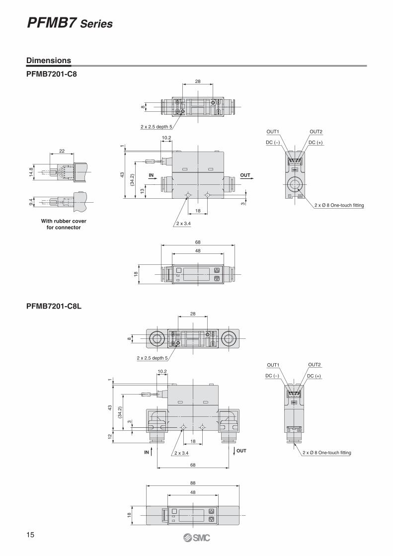
18
48
68
1 IN
OUT1
DC (−)
OUT2
DC (+)
2 x Ø 8 One-touch fitting18
10.2
143
3
13
(34.2
)
2 x 3.4
IN OUT
28
8
2 x 2.5 depth 5
22
14.8
9.4
1 IN
2 x Ø 8 One-touch fitting
OUT1
DC (−)
OUT2
DC (+)
18
48
88
18
68
10.2
3
(34.2
)
143
12
2 x 3.4OUTIN
28
8
2 x 2.5 depth 5
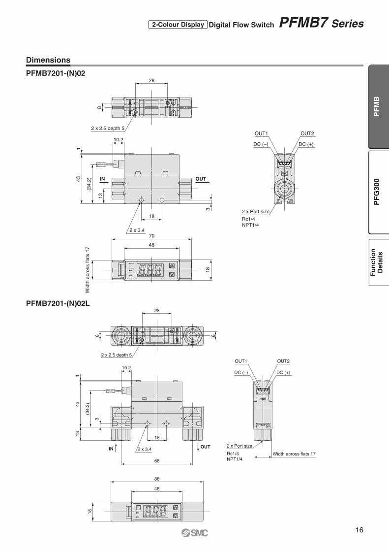
Dimensions
PFMB7201-C8
PFMB7201-C8L
With rubber cover
for connector
15
PFMB7 Series
48
70
Wid
th a
cro
ss f
lats
17
18
1 IN
2 x Port size
Rc1/4
NPT1/4
DC (+)DC (−)
OUT2OUT1
2 x 3.4
18
14
3
13
10.2
3
(34
.2) IN OUT
28
8
2 x 2.5 depth 5
88
48
18
1 IN
Width across flats 17
DC (+)DC (−)
OUT2OUT1
2 x Port size
Rc1/4
NPT1/468
3
(34
.2)
18
43
10.2
11
3
2 x 3.4IN OUT
28
8
2 x 2.5 depth 5
8
Dimensions
PFMB7201-(N)02
PFMB7201-(N)02L
16
2-Colour Display Digital Flow Switch PFMB7 Series
PF
G3
00
PF
MB
Fu
ncti
on
Deta
ils
1 IN
18
OUT1
DC (−)
OUT2
DC (+)
2 x Port size
G1/418
10.2
13
(34.2
)
43
1
32 x 3.4
IN OUT
48
78
Wid
th a
cro
ss fla
ts 2
1
2 x 2.5 depth 5
8
28
1 IN
Width across flats 21
DC (+)
OUT2
2 x Port size
G1/4
OUT1
DC (−)
88
48
18
18
2 x 3.4
68
17
43
1
3
(34.2
)
10.2
IN OUT
8
28
2 x 2.5 depth 5
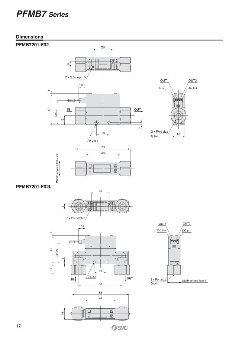
Dimensions
PFMB7201-F02
PFMB7201-F02L
17
PFMB7 Series

1 IN
DC (−)
OUT1
DC (+)
OUT2
2 x Ø 8 One-touch fitting
18
48
58
76
96
51.5
(M
ax. 58.5
)
13
(34.2
)
3
10.2
43
1
18
2 x 3.4
IN OUT
28 20
8
3 x 2.5 depth 5
18
48
58
88
1 IN
DC (+)DC (−)
OUT2OUT1
2 x Ø 8 One-touch fitting
10.2
3
(34
.2)
12
43
1
18
68
51
.5 (
Ma
x.
58
.5)
2 x 3.4IN OUT
2 x 2.5 depth 5
28
8
Dimensions
PFMB7201S-C8
PFMB7201S-C8L
18
2-Colour Display Digital Flow Switch PFMB7 Series
PF
G3
00
PF
MB
Fu
ncti
on
Deta
ils
1 IN
DC (−)
OUT1 OUT2
DC (+)
2 x Port size
Rc1/4
NPT1/4
18
48
58
76
98
Wid
th a
cro
ss fla
ts 1
7
18
13
(34.2
)
43
1
10.2
51.5
(M
ax. 58.5
)
3
2 x 3.4
IN OUT
28 20
8
3 x 2.5 depth 5
1 IN
Width across flats 17
DC (+)DC (−)
OUT2OUT1
2 x Port size
Rc1/4
NPT1/4
48
58
88
18
10.2
3
(34.2
)
18
68
13
43
1
51.5
(M
ax. 58.5
)
2 x 3.4IN OUT
8
28
2 x 2.5 depth 5
8
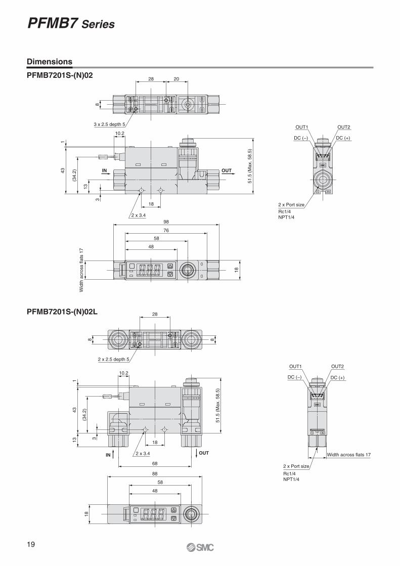
Dimensions
PFMB7201S-(N)02
PFMB7201S-(N)02L
19
PFMB7 Series
1 IN
2 x Port size
G1/4
OUT2
DC (+)
OUT1
DC (−)
Wid
th a
cro
ss f
lats
21
106
76
58
48
18
2 x 3.4
51
.5 (
Ma
x. 5
8.5
)
10.2
18
43
1
13
(34
.2)
3
IN OUT
28 20
8
3 x 2.5 depth 5
1 IN
Width across flats 212 x Port size
OUT2
DC (+)DC (−)
OUT1
G1/4
18
88
58
48
51.5
(M
ax. 58.5
)
68
2 x 3.4
1817
43
3
(34.2
)
1
10.2
IN OUT
28
8
2 x 2.5 depth 5
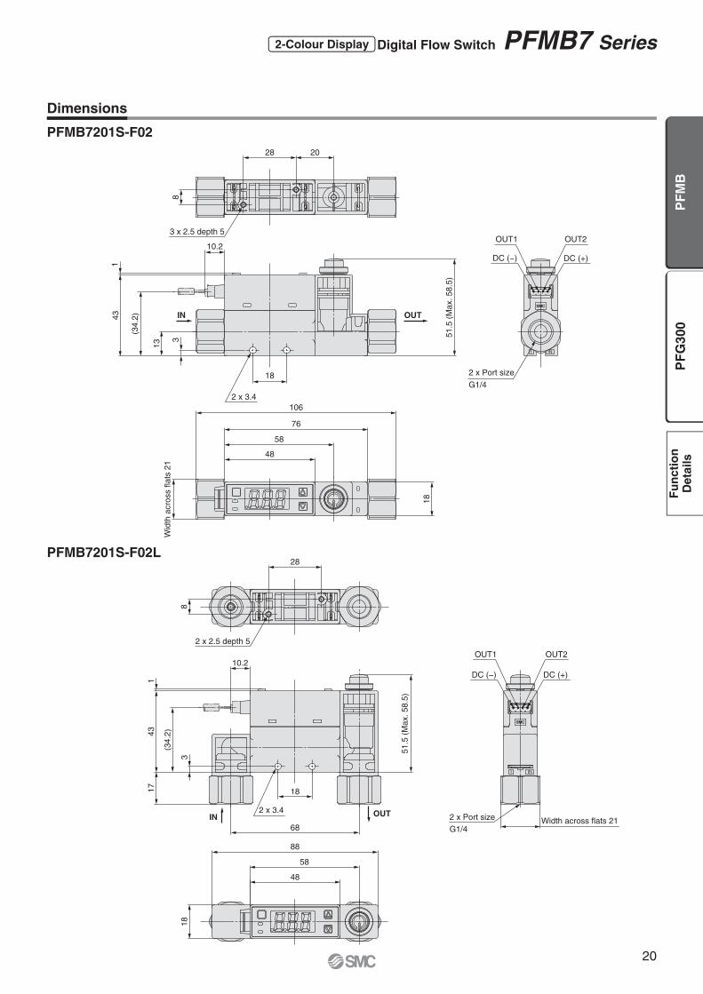
Dimensions
PFMB7201S-F02
PFMB7201S-F02L
20
2-Colour Display Digital Flow Switch PFMB7 Series
PF
G3
00
PF
MB
Fu
ncti
on
Deta
ils

68
58
28
29
.9
OUT
Pa
ne
l th
ickn
ess 1
to
3.2
42
.53
IN
29.9
28
18
88
58
342.5
Panel th
ickness 1
to 3
.2
94 or more ∗1
54 +0.50
34
or
mo
re
24
+0
.50
4 x R3 or less
4 x R3 or less
4 x R3 or less
78
28
29
.9
3
Pa
ne
l th
ickn
ess
1 t
o 3
.2
51
.5 (
Ma
x.
58
.5)
76
96
42
.53
93
78
18
28
29
.9
42
.53
Pa
ne
l th
ickn
ess
1 t
o 3
.2
51
.5 (
Ma
x.
58
.5)
94 or more ∗1
74 +0.50
34 o
r m
ore
24
+0.5
0
4 x R3 or less
4 x R3 or less 4 x R3 or less
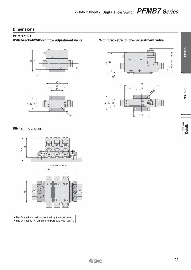
Dimensions
PFMB7201Panel mount/
Without fl ow adjustment valve/Straight
Panel mount/
With fl ow adjustment valve/Straight
Panel mount/
Without fl ow adjustment valve/Bottom
Panel mount/
With fl ow adjustment valve/Bottom
∗1 Piping entry direction: Minimum dimensions for bottom piping. If using straight
piping, the piping material and tubing need to be taken into consideration
when designing the system. If a bend (R) is used, limit it to R3 or less.
Panel Fitting Dimensions
Panel thickness 1 to 3.2 mm
∗1 Piping entry direction: Minimum dimensions for bottom piping. If using straight
piping, the piping material and tubing need to be taken into consideration
when designing the system. If a bend (R) is used, limit it to R3 or less.
Panel Fitting Dimensions
Panel thickness 1 to 3.2 mm
21
PFMB7 Series
43
1.2
48
18
48
36
28
34
26
18
4 x 3.4
34
26
18
24 28
76
4 x
3.4
361
.2
51
.5 (
Ma
x. 5
8.5
)
18
43
48
18 x n pcs. + 34.4
18
48
11IN1 IN IN
43
52.4
Dimensions
• The DIN rail should be provided by the customer.
• The DIN rail is not suitable for port size F02 (G1/4).
PFMB7201With bracket/Without fl ow adjustment valve With bracket/With fl ow adjustment valve
DIN rail mounting
22
2-Colour Display Digital Flow Switch PFMB7 Series
PF
G3
00
PF
MB
Fu
ncti
on
Deta
ils
OUTIN
2 x Port size
1.5D
E
F
5
1.5
LK
N
4 x
Ø 2
.7 d
epth
4
A
B
S T
U
WV
42H
(10.2)
4 x 4.5
(5)
Brown
White
Black
Blue
(6.5)
+2
1−
(2020)
(20)
(30)
Terminal semi-stripped
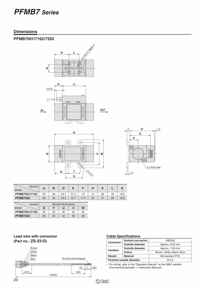
PFMB7501/7102/7202
Symbol
ModelA B D E F H K L N
PFMB7501/7102 70 30 43.7 37.2 15 14 26 18 13.6
PFMB7202 90 35 49.2 42.7 17.5 24 31 28 16.8
Symbol
Model
Bracket dimensions
S T U V W
PFMB7501/7102 24 22 32 40 50
PFMB7202 30 30 42 48 58
Dimensions
Lead wire with connector
(Part no.: ZS-33-D)
Cable Specifi cations
∗ For wiring, refer to the “Operation Manual” on the SMC website.
Documents/Download --> Instruction Manuals
ConductorNominal cross section AWG26
Outside diameter Approx. 0.50 mm
InsulatorOutside diameter Approx. 1.00 mm
Colour Brown, White, Black, Blue
Sheath Material Oil-resistant PVC
Finished outside diameter Ø 3.5
23
PFMB7 Series

RoHS
How to Order
M L
Option 3
— None
F
ZS-28-C-1
Sensorconnector
Option 4
Operation manual Calibration certifi cate
— � —
Y — —
K � �
T — �
Options/Part Nos.When only optional parts are required, order with the part numbers listed below.
Part no. Option Note
ZS-28-C-1 Sensor connector For PFMB
ZS-46-A1 Bracket A Tapping screw: Nominal size 3 x 8 L (2 pcs.)
ZS-46-A2 Bracket B Tapping screw: Nominal size 3 x 8 L (2 pcs.)
ZS-46-B Panel mount adapter
ZS-46-D Panel mount adapter + Front protection cover
ZS-46-5L Power supply/output connection lead wire 5-core, 2 m
ZS-27-01 Front protection cover
Connection Example
PFG RT03 0
PFG300 Series
Digital Flow Monitor
3-Screen Display
Option 2
Symbol Description
— None
A1Bracket A (Vertical mounting)
ZS-46-A1
A2Bracket B (Horizontal mounting)
ZS-46-A2
BPanel mount adapter
ZS-46-B
DPanel mount adapter + Front protection cover
ZS-46-D
Option 1
Symbol Description
— Without lead wire
LPower supply/output
connection lead wire
(Lead wire length: 2 m)
ZS-46-5L
Power supply/outputconnection lead wire
PFG300 PFG300
PFMB7201 PFMB7501/7102/7202
Sensorconnector
Sensorconnector
Lead wire with connector
(Option for PFMB)
Power supply/outputconnection lead wire
Unit specification
— Units selection function
M SI unit only∗3
∗3 Fixed unit: Instantaneous fl ow: l/min
Accumulated fl ow: L
Output specification
RT2 outputs (NPN/PNP switching type)
+ Analogue voltage output∗1, 2
SV2 outputs (NPN/PNP switching type)
+ Analogue current output∗2
XY2 outputs (NPN/PNP switching type)
+ Copy function
∗1 Can switch between 1 to 5 V and
0 to 10 V
∗2 Can be switched to external input
or copy function
Input specification
Symbol Description Applicable fl ow switch model
0 Voltage input PFMB7�-C/E series
1 Current input PFMB7�-D/F series
Type
3 Remote type monitor unit
24
PF
G3
00
PF
MB
Fu
ncti
on
Deta
ils
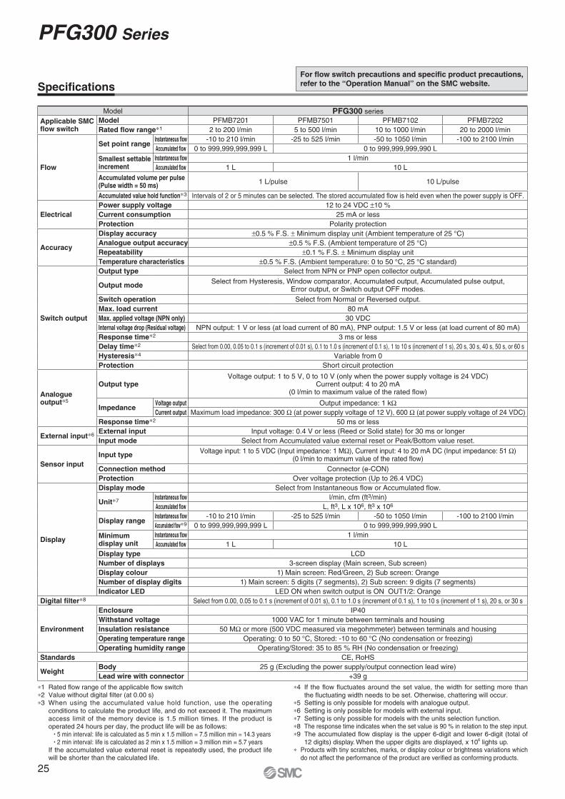
Specifi cations
Model PFG300 series
Applicable SMC fl ow switch
Model PFMB7201 PFMB7501 PFMB7102 PFMB7202
Rated fl ow range∗1 2 to 200 l/min 5 to 500 l/min 10 to 1000 l/min 20 to 2000 l/min
Flow
Set point rangeInstantaneous fl ow -10 to 210 l/min -25 to 525 l/min -50 to 1050 l/min -100 to 2100 l/min
Accumulated fl ow 0 to 999,999,999,999 L 0 to 999,999,999,990 L
Smallest settable increment
Instantaneous fl ow 1 l/min
Accumulated fl ow 1 L 10 L
Accumulated volume per pulse (Pulse width = 50 ms)
1 L/pulse 10 L/pulse
Accumulated value hold function∗3 Intervals of 2 or 5 minutes can be selected. The stored accumulated fl ow is held even when the power supply is OFF.
Electrical
Power supply voltage 12 to 24 VDC ±10 %
Current consumption 25 mA or less
Protection Polarity protection
Accuracy
Display accuracy ±0.5 % F.S. ± Minimum display unit (Ambient temperature of 25 °C)
Analogue output accuracy ±0.5 % F.S. (Ambient temperature of 25 °C)
Repeatability ±0.1 % F.S. ± Minimum display unit
Temperature characteristics ±0.5 % F.S. (Ambient temperature: 0 to 50 °C, 25 °C standard)
Switch output
Output type Select from NPN or PNP open collector output.
Output modeSelect from Hysteresis, Window comparator, Accumulated output, Accumulated pulse output,
Error output, or Switch output OFF modes.
Switch operation Select from Normal or Reversed output.
Max. load current 80 mA
Max. applied voltage (NPN only) 30 VDC
Internal voltage drop (Residual voltage) NPN output: 1 V or less (at load current of 80 mA), PNP output: 1.5 V or less (at load current of 80 mA)
Response time∗2 3 ms or less
Delay time∗2 Select from 0.00, 0.05 to 0.1 s (increment of 0.01 s), 0.1 to 1.0 s (increment of 0.1 s), 1 to 10 s (increment of 1 s), 20 s, 30 s, 40 s, 50 s, or 60 s
Hysteresis∗4 Variable from 0
Protection Short circuit protection
Analogue output∗5
Output typeVoltage output: 1 to 5 V, 0 to 10 V (only when the power supply voltage is 24 VDC)
Current output: 4 to 20 mA(0 l/min to maximum value of the rated fl ow)
ImpedanceVoltage output Output impedance: 1 kΩCurrent output Maximum load impedance: 300 Ω (at power supply voltage of 12 V), 600 Ω (at power supply voltage of 24 VDC)
Response time∗2 50 ms or less
External input∗6External input Input voltage: 0.4 V or less (Reed or Solid state) for 30 ms or longer
Input mode Select from Accumulated value external reset or Peak/Bottom value reset.
Sensor input
Input typeVoltage input: 1 to 5 VDC (Input impedance: 1 MΩ), Current input: 4 to 20 mA DC (Input impedance: 51 Ω)
(0 l/min to maximum value of the rated fl ow)
Connection method Connector (e-CON)
Protection Over voltage protection (Up to 26.4 VDC)
Display
Display mode Select from Instantaneous fl ow or Accumulated fl ow.
Unit∗7Instantaneous fl ow l/min, cfm (ft3/min)
Accumulated fl ow L, ft3, L x 106, ft3 x 106
Display rangeInstantaneous fl ow -10 to 210 l/min -25 to 525 l/min -50 to 1050 l/min -100 to 2100 l/min
Accumulated fl ow∗9 0 to 999,999,999,999 L 0 to 999,999,999,990 L
Minimum display unit
Instantaneous fl ow 1 l/min
Accumulated fl ow 1 L 10 L
Display type LCD
Number of displays 3-screen display (Main screen, Sub screen)
Display colour 1) Main screen: Red/Green, 2) Sub screen: Orange
Number of display digits 1) Main screen: 5 digits (7 segments), 2) Sub screen: 9 digits (7 segments)
Indicator LED LED ON when switch output is ON OUT1/2: Orange
Digital fi lter∗8 Select from 0.00, 0.05 to 0.1 s (increment of 0.01 s), 0.1 to 1.0 s (increment of 0.1 s), 1 to 10 s (increment of 1 s), 20 s, or 30 s
Environment
Enclosure IP40
Withstand voltage 1000 VAC for 1 minute between terminals and housing
Insulation resistance 50 MΩ or more (500 VDC measured via megohmmeter) between terminals and housing
Operating temperature range Operating: 0 to 50 °C, Stored: -10 to 60 °C (No condensation or freezing)
Operating humidity range Operating/Stored: 35 to 85 % RH (No condensation or freezing)
Standards CE, RoHS
WeightBody 25 g (Excluding the power supply/output connection lead wire)
Lead wire with connector +39 g
∗1 Rated fl ow range of the applicable fl ow switch
∗2 Value without digital fi lter (at 0.00 s)
∗3 When using the accumulated value hold function, use the operating
conditions to calculate the product life, and do not exceed it. The maximum access limit of the memory device is 1.5 million times. If the product is operated 24 hours per day, the product life will be as follows:
• 5 min interval: life is calculated as 5 min x 1.5 million = 7.5 million min = 14.3 years• 2 min interval: life is calculated as 2 min x 1.5 million = 3 million min = 5.7 years
If the accumulated value external reset is repeatedly used, the product life will be shorter than the calculated life.
∗4 If the fl ow fl uctuates around the set value, the width for setting more than
the fl uctuating width needs to be set. Otherwise, chattering will occur.∗5 Setting is only possible for models with analogue output.
∗6 Setting is only possible for models with external input.
∗7 Setting is only possible for models with the units selection function.
∗8 The response time indicates when the set value is 90 % in relation to the step input.
∗9 The accumulated fl ow display is the upper 6-digit and lower 6-digit (total of
12 digits) display. When the upper digits are displayed, x 106 lights up.
∗ Products with tiny scratches, marks, or display colour or brightness variations which
do not affect the performance of the product are verifi ed as conforming products.
For fl ow switch precautions and specifi c product precautions,
refer to the “Operation Manual” on the SMC website.
25
PFG300 Series
12 to 24 VDC
Brown DC (+)
White OUT2
Grey Copy terminal
Black OUT1
Blue DC (−)
+
−
12 to 24 VDC
Brown DC (+)
White OUT2
Grey Copy terminal
Black OUT1
Blue DC (−)
+
−
12 to 24 VDC
Brown DC (+)
White OUT2
Grey Analogue output
Black OUT1
Blue DC (−)
+
−
U
12 to 24 VDC
Brown DC (+)
White OUT2
Grey External input
Black OUT1
Blue DC (−)
+
−
12 to 24 VDC
Brown DC (+)
White OUT2
Grey Analogue output
Black OUT1
Blue DC (−)
+
−
U
12 to 24 VDC
Brown DC (+)
White OUT2
Grey External input
Black OUT1
Blue DC (−)
+
−
qDC (+)
rAnalogue input
eDC (−)
qDC (+)
rAnalogue input
eDC (−)
qDC (+)
rAnalogue input
eDC (−)
Main
circuit
Ma
in c
ircu
itM
ain
circu
it
Sensor
Se
nso
rS
en
so
r
qDC (+)
rAnalogue input
eDC (−)
qDC (+)
rAnalogue input
eDC (−)
qDC (+)
rAnalogue input
eDC (−)
Sensor
Se
nso
rS
en
so
r
Main
circuit
Ma
in c
ircu
itM
ain
circu
it
LoadL
oad
Lo
ad
Lo
ad
Lo
ad L
oa
d
Lo
ad
Load
Lo
ad
Load L
oad
Load L
oad
Lo
ad
Max. 28 V, 80 mA
Black OUT1
White OUT2
Blue DC (−)
Load
Load
Max. 80 mA
Brown DC (+)
Black OUT1
White OUT2
Load
Load
0 V
50 ms 50 ms
0 V
50 ms 50 ms
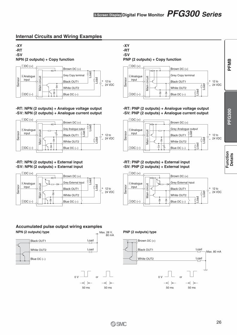
Internal Circuits and Wiring Examples
-XY
-RT
-SV
NPN (2 outputs) + Copy function
-RT: NPN (2 outputs) + Analogue voltage output
-SV: NPN (2 outputs) + Analogue current output
-RT: NPN (2 outputs) + External input
-SV: NPN (2 outputs) + External input
-XY
-RT
-SV
PNP (2 outputs) + Copy function
-RT: PNP (2 outputs) + Analogue voltage output
-SV: PNP (2 outputs) + Analogue current output
-RT: PNP (2 outputs) + External input
-SV: PNP (2 outputs) + External input
or or
NPN (2 outputs) type PNP (2 outputs) type
Accumulated pulse output wiring examples
26
3-Screen Display Digital Flow Monitor PFG300 Series
PF
G3
00
PF
MB
Fu
ncti
on
Deta
ils

25
34.6
30
30
30
20
45
30
2
19
5.2
9.6 14
.7
47
25
22
30
20
5.2
20
20
45
20
9.1
13.6
∗ Bracket configuration allows for mounting in four orientations.
∗ Bracket configuration allows for mounting in four orientations.
1.6
7.27.25.2
5.2
5.2
30
30
251.5 2.7
(7.7)
20
20
Sensor connector
4 x Ø 2.6
Depth 7 or less
Power supply/Output connector
Dimensions
Bracket A
(Part no.: ZS-46-A1)
Bracket B
(Part no.: ZS-46-A2)
27
PFG300 Series

4 3 2 1
47.8
50.8
21
20.24.8 34.5
34
.5
6.3 Panel thickness 0.5 to 7
42.4
33.5
34.5
33.5
34.520.211
Panel thickness 0.5 to 7
21
47.8
50.8
R4.5 R4.5
R4.5R4.5
Blue DC (−)
Grey FUNC
White OUT2Brown DC (+)
Black OUT1
(2000)
12.35
15.6
16.1
18.5
5
Dimensions
Panel mount adapter
(Part no.: ZS-46-B)
Panel mount adapter + Front protection cover
(Part no.: ZS-46-D)
Power supply/output connection lead wire
(Part no.: ZS-46-5L)
Sensor connector
(Part no.: ZS-28-C-1)
∗1 1 to 5 V or 4 to 20 mA
Pin no. Terminal
1 DC (+)
2 N.C.
3 DC (−)
4 IN∗1
Cable Specifi cationsConductor cross section 0.15 mm2 (AWG26)
InsulatorOutside diameter 1.0 mm
Colour Brown, Blue, Black, White, Grey (5-core)
Sheath Finished outside diameter Ø 3.5
28
3-Screen Display Digital Flow Monitor PFG300 Series
PF
G3
00
PF
MB
Fu
ncti
on
Deta
ils
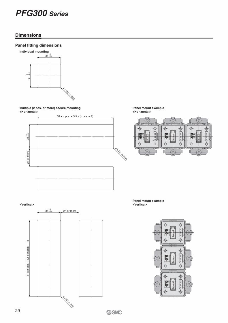
4 x R2 or less
310
−0.4
31
0−
0.4
31 x n pcs. + 3.5 x (n pcs. − 1)
4 x R2 or less
24 o
r m
ore
31
0−
0.4
24 or more
31 x
n p
cs. +
3.5
x (
n p
cs. −
1)
4 x R2 or less
310
−0.4
Dimensions
Multiple (2 pcs. or more) secure mounting
<Horizontal>
Panel mount example
<Horizontal>
Panel mount example
<Vertical><Vertical>
Panel fi tting dimensions
Individual mounting
29
PFG300 Series
Can be changed
10 1000
At a tim
e of shipment
1
5
01050100
10 % of the
rated flow range
100 % of the
rated flow range
Maximum value of
the display range
Flow [l/min]
1000 l/min type
An
alo
gu
e o
utp
ut [V
]
Reversible display function
When display is upside down.
INOUT
INOUT
PFMB Series
Function Details
� Output operation
The output operation can be selected from the following:
Output (hysteresis mode and window comparator mode) corresponding
to instantaneous flow or output (accumulated output and pulse
output) corresponding to accumulated fl ow.
(Default setting: Hysteresis mode, Normal output)
Green for ON, Red for OFF
Red for ON, Green for OFF
Red all the time
Green all the time
� Display colour
The display colour can be selected for
each output condition. The selection of
the display colour provides visual iden-
tifi cation of abnormal values. (The display
colour depends on OUT1 setting.)
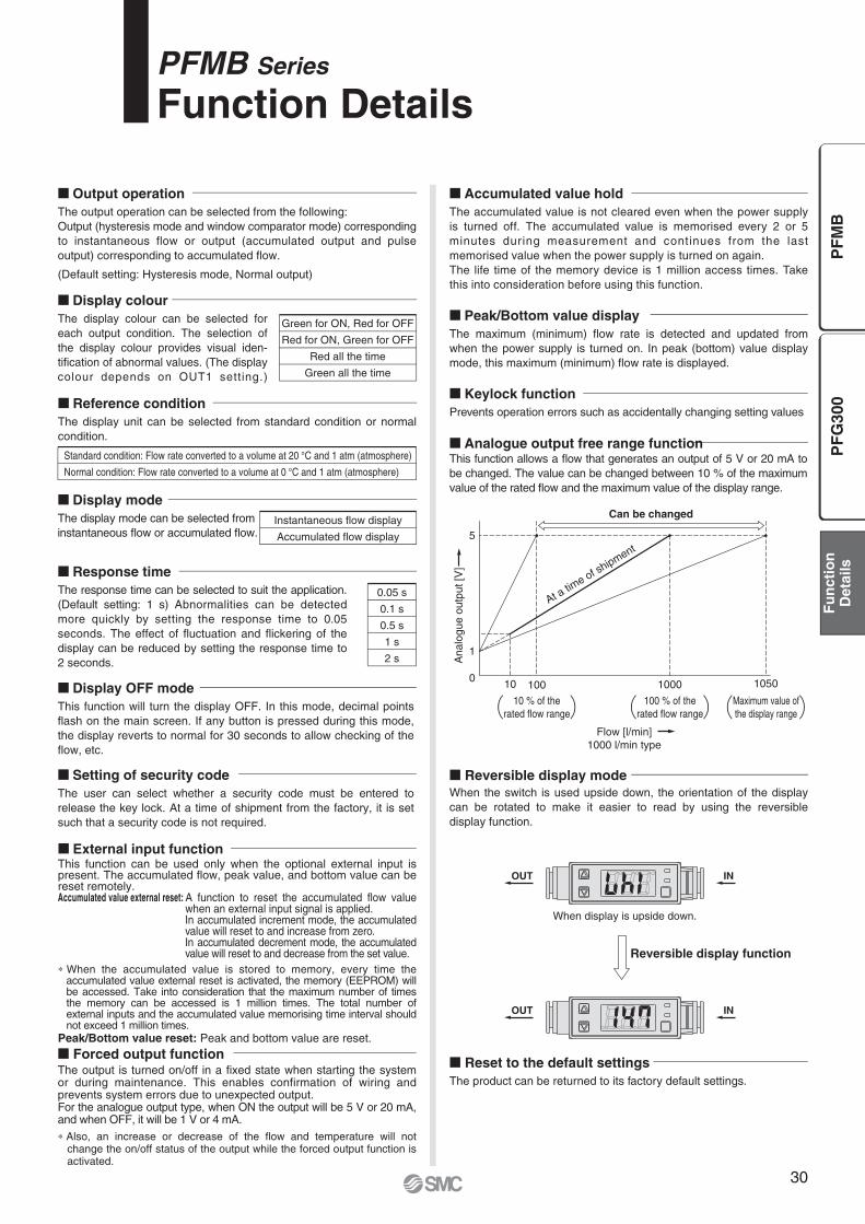
� External input functionThis function can be used only when the optional external input is present. The accumulated fl ow, peak value, and bottom value can be reset remotely.Accumulated value external reset: A function to reset the accumulated fl ow value
when an external input signal is applied.In accumulated increment mode, the accumulated value will reset to and increase from zero.In accumulated decrement mode, the accumulated value will reset to and decrease from the set value.
∗ When the accumulated value is stored to memory, every time the accumulated value external reset is activated, the memory (EEPROM) will be accessed. Take into consideration that the maximum number of times the memory can be accessed is 1 million times. The total number of external inputs and the accumulated value memorising time interval should not exceed 1 million times.
Peak/Bottom value reset: Peak and bottom value are reset.
� Forced output functionThe output is turned on/off in a fi xed state when starting the system or during maintenance. This enables confirmation of wiring and prevents system errors due to unexpected output.For the analogue output type, when ON the output will be 5 V or 20 mA, and when OFF, it will be 1 V or 4 mA.
∗ Also, an increase or decrease of the fl ow and temperature will not change the on/off status of the output while the forced output function is activated.
� Accumulated value hold
The accumulated value is not cleared even when the power supply
is turned off. The accumulated value is memorised every 2 or 5
minutes during measurement and continues from the last
memorised value when the power supply is turned on again.
The life time of the memory device is 1 million access times. Take
this into consideration before using this function.
� Reset to the default settings
The product can be returned to its factory default settings.
� Display OFF mode
This function will turn the display OFF. In this mode, decimal points
fl ash on the main screen. If any button is pressed during this mode,
the display reverts to normal for 30 seconds to allow checking of the
fl ow, etc.
� Setting of security code
The user can select whether a security code must be entered to
release the key lock. At a time of shipment from the factory, it is set
such that a security code is not required.
� Peak/Bottom value display
The maximum (minimum) fl ow rate is detected and updated from
when the power supply is turned on. In peak (bottom) value display
mode, this maximum (minimum) fl ow rate is displayed.
� Keylock function
Prevents operation errors such as accidentally changing setting values
Standard condition: Flow rate converted to a volume at 20 °C and 1 atm (atmosphere)
Normal condition: Flow rate converted to a volume at 0 °C and 1 atm (atmosphere)
� Reference condition
The display unit can be selected from standard condition or normal
condition.
� Display mode
The display mode can be selected from
instantaneous fl ow or accumulated fl ow.Instantaneous fl ow display
Accumulated fl ow display
� Response time
The response time can be selected to suit the application.
(Default setting: 1 s) Abnormalities can be detected
more quickly by setting the response time to 0.05
seconds. The effect of fl uctuation and fl ickering of the
display can be reduced by setting the response time to
2 seconds.
0.05 s
0.1 s
0.5 s
1 s
2 s
� Analogue output free range functionThis function allows a fl ow that generates an output of 5 V or 20 mA to
be changed. The value can be changed between 10 % of the maximum
value of the rated fl ow and the maximum value of the display range.
� Reversible display mode
When the switch is used upside down, the orientation of the display
can be rotated to make it easier to read by using the reversible
display function.
30
PF
G3
00
PF
MB
Fu
ncti
on
Deta
ils
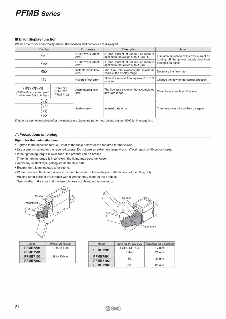
Piping for the metal attachment
• Tighten to the specifi ed torque. Refer to the table below for the required torque values.
• Use a wrench suited for the required torque. Do not use an extremely large wrench (Total length of 40 cm or more).
• If the tightening torque is exceeded, the product can be broken.
If the tightening torque is insuffi cient, the fi tting may become loose.
• Avoid any sealant tape getting inside the fl ow path.
• Ensure there is no leakage after piping.
• When mounting the fi tting, a wrench should be used on the metal part (attachment) of the fi tting only.
Holding other parts of the product with a wrench may damage the product.
Specifi cally, make sure that the wrench does not damage the connector.
Model Required torque
PFMB7201 12 to 14 N·m
PFMB7501
28 to 30 N·mPFMB7102
PFMB7202
Model Nominal thread size Width across fl ats of attachment
PFMB7201Rc1/4, NPT1/4 17 mm
G1/4 21 mm
PFMB75011/2 30 mm
PFMB7102
PFMB7202 3/4 35 mm
Attachment
CautionCaution
Attachment
� Error display function
When an error or abnormality arises, the location and contents are displayed.
If the error cannot be solved after the instructions above are performed, please contact SMC for investigation.
Display Error name Description Action
OUT1 over currenterror
A load current of 80 mA or more is applied to the switch output (OUT1). Eliminate the cause of the over current by
turning off the power supply and then
turning it on again.OUT2 over currenterror
A load current of 80 mA or more is applied to the switch output (OUT2).
Instantaneous fl ow error
The flow rate exceeds the maximum value of the display range.
Decrease the fl ow rate.
Reverse fl ow errorThere is a reverse fl ow equivalent to -5 % or more.
Change the fl ow to the correct direction.
PFMB7201
PFMB7501
PFMB7102
Accumulated fl owerror
The fl ow rate exceeds the accumulated
fl ow rate range.Clear the accumulated fl ow rate.
System error Internal data error Turn the power off and then on again.
“999” will fl ash in any of upper,middle, lower 3-digit displays.
Precautions on piping
31
PFMB Series
Green for ON, Red for OFF
Red for ON, Green for OFF
Red all the time
Green all the time
0.00 s
0.05 to 0.1 s (increment of 0.01 s)
0.1 to 1.0 s (increment of 0.1 s)
1 to 10 s (increment of 1 s)
20 s
30 s
40 s
50 s
60 s
0.00 s
0.05 to 0.1 s (increment of 0.01 s)
0.1 to 1.0 s (increment of 0.1 s)
1 to 10 s (increment of 1 s)
20 s
30 s
PFG300 Series
Function Details
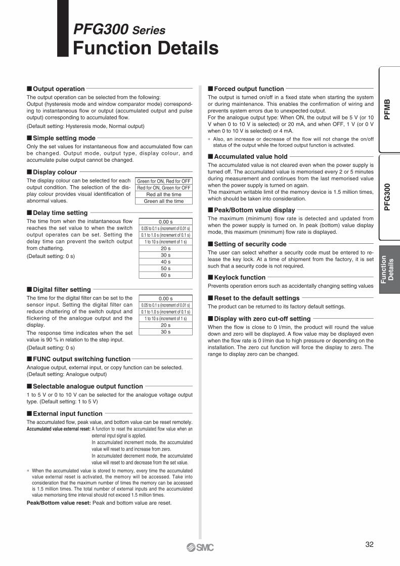
� Display colour
The display colour can be selected for each
output condition. The selection of the dis-
play colour provides visual identifi cation of
abnormal values.
� Simple setting mode
Only the set values for instantaneous fl ow and accumulated fl ow can
be changed. Output mode, output type, display colour, and
accumulate pulse output cannot be changed.
� Output operation
The output operation can be selected from the following:
Output (hysteresis mode and window comparator mode) correspond-
ing to instantaneous flow or output (accumulated output and pulse
output) corresponding to accumulated fl ow.
(Default setting: Hysteresis mode, Normal output)
� External input function
The accumulated fl ow, peak value, and bottom value can be reset remotely.
Accumulated value external reset: A function to reset the accumulated fl ow value when an
external input signal is applied.
In accumulated increment mode, the accumulated
value will reset to and increase from zero.
In accumulated decrement mode, the accumulated
value will reset to and decrease from the set value.
∗ When the accumulated value is stored to memory, every time the accumulated
value external reset is activated, the memory will be accessed. Take into
consideration that the maximum number of times the memory can be accessed
is 1.5 million times. The total number of external inputs and the accumulated
value memorising time interval should not exceed 1.5 million times.
Peak/Bottom value reset: Peak and bottom value are reset.
� Forced output function
The output is turned on/off in a fi xed state when starting the system
or during maintenance. This enables the confi rmation of wiring and
prevents system errors due to unexpected output.
For the analogue output type: When ON, the output will be 5 V (or 10
V when 0 to 10 V is selected) or 20 mA, and when OFF, 1 V (or 0 V
when 0 to 10 V is selected) or 4 mA.
∗ Also, an increase or decrease of the flow will not change the on/off
status of the output while the forced output function is activated.
� Accumulated value hold
The accumulated value is not cleared even when the power supply is
turned off. The accumulated value is memorised every 2 or 5 minutes
during measurement and continues from the last memorised value
when the power supply is turned on again.
The maximum writable limit of the memory device is 1.5 million times,
which should be taken into consideration.
� Peak/Bottom value display
The maximum (minimum) flow rate is detected and updated from
when the power supply is turned on. In peak (bottom) value display
mode, this maximum (minimum) fl ow rate is displayed.
� Setting of security code
The user can select whether a security code must be entered to re-
lease the key lock. At a time of shipment from the factory, it is set
such that a security code is not required.
� Keylock function
Prevents operation errors such as accidentally changing setting values
� Display with zero cut-off setting
When the flow is close to 0 l/min, the product will round the value
down and zero will be displayed. A fl ow value may be displayed even
when the fl ow rate is 0 l/min due to high pressure or depending on the
installation. The zero cut function will force the display to zero. The
range to display zero can be changed.� FUNC output switching function
Analogue output, external input, or copy function can be selected.
(Default setting: Analogue output)
� Selectable analogue output function
1 to 5 V or 0 to 10 V can be selected for the analogue voltage output
type. (Default setting: 1 to 5 V)
� Reset to the default settings
The product can be returned to its factory default settings.
� Delay time setting
The time from when the instantaneous fl ow
reaches the set value to when the switch
output operates can be set. Setting the
delay time can prevent the switch output
from chattering.
(Default setting: 0 s)
� Digital fi lter setting
The time for the digital fi lter can be set to the
sensor input. Setting the digital filter can
reduce chattering of the switch output and
flickering of the analogue output and the
display.
The response time indicates when the set
value is 90 % in relation to the step input.
(Default setting: 0 s)
32
PF
G3
00
PF
MB
Fu
ncti
on
Deta
ils

� Selection of display on sub screen
The display on the sub screen in measuring mode can be set.
Set value display Accumulated value display Peak value display
Displays the set value Displays the accumulated value Displays the peak value
Bottom value display Line name display OFF
Displays the bottom value Displays the line name
(Up to 5 alphanumeric
characters can be input.)
Displays nothing
� Analogue output free range function
This function allows a fl ow that generates an output of 5 V (or 10 V when 0 to 10 V
is selected) or 20 mA to be changed. The value can be changed between 10 % of
the maximum value of the rated fl ow and the maximum value of the display range. For analogue voltage output of 0 to 10 V
� Error display function
When an error or abnormality arises, the location and contents are displayed.
Display Error name Description Action
OUT over current errorA load current of 80 mA or more is applied to the switch output (OUT).
Eliminate the cause of the over current by turning
off the power supply and then turning it on again.
Instantaneous flow error The flow rate exceeds the maximum value of the display range. Decrease the flow rate.
Reverse fl ow error There is a reverse fl ow equivalent to –5 % or more. Change the fl ow to the correct direction.
fl ashes
x 106Accumulated flow error The flow rate exceeds the accumulated flow rate range. Clear the accumulated flow rate.
System error Internal data error Turn the power off and then on again.
Copy error The copy function does not operate properly.
After clearing the error by pressing the and
buttons simultaneously for a minimum of 1 second, check
the wiring and the model, and then attempt to copy again.
If the error cannot be solved after the instructions above are performed, please contact SMC for investigation.
Subscreen
Can be changed
20 2000
At a tim
e of shipment
1
5
0
An
alo
gu
e o
utp
ut [V
]
2100200
10 % of the rated
flow range
100 % of the rated
flow range
Maximum value of
the display range
Flow [l/min]
2000 l/min type
Can be changed
20 2000
At a tim
e of shipment
10
02100200
10 % of the rated
flow range
100 % of the rated
flow range
Maximum value of
the display range
Flow [l/min]
2000 l/min type
An
alo
gu
e o
utp
ut [V
]
33
PFG300 Series

Master Slaves
(Max. 10 units)
1 unit 2 units
·········
10 units
DC
(+)
OU
T1
OU
T2
FU
NC
DC
(−)
Grey (C
opy wire)
DC
(+)
OU
T1
OU
T2
FU
NC
DC
(−)
DC
(+)
OU
T1
OU
T2
FU
NC
DC
(−)
DC
(+)
OU
T1
OU
T2
FU
NC
DC
(−)
Power supply
Slave monitors
1 unit 2 unitsn units
(Max. 10 units)Master monitor
Blu
e
Bro
wn
Blu
e
Bro
wn
Grey (C
opy wire)
Blu
e
Bro
wn
Grey (C
opy wire)
Blu
e
Bro
wn
Grey (C
opy wire)
1) Wire as shown in the fi gure on the left.
2) Select the slave monitor which is to be the master, and
change it into a master using the buttons. (In the default
setting, all fl ow monitors are set as slaves.)
3) Press the e button on the master monitor to start
copying.
eeeee
� Copy function
The settings of the master monitor can be copied to the slave monitors,
reducing setting labour and minimizing the risk of setting mistakes.
The set value can be copied to up to 10 fl ow monitors simultaneously.
(Maximum transmission distance: 4 m)
� Selection of power saving mode
Power saving mode can be selected.
It shifts to the power saving mode without button operation for 30 seconds.
It is set to the normal mode (Power saving mode is OFF.) at a time of shipment from the factory.
(During power saving mode, [ECo] will fl ash in the sub screen and the operation light is ON (only when the switch is ON).)
∗ There may be a difference in the displayed value on the connected fl ow switch and the fl ow monitor. When the fl ow monitor display is being
used, it is recommended to set the fl ow switch display to OFF mode.
34
Function Details PFG300 Series
PF
G3
00
PF
MB
Fu
ncti
on
Deta
ils
Lithuania +370 5 2308118 www.smclt.lt [email protected] +31 (0)205318888 www.smcpneumatics.nl [email protected] +47 67129020 www.smc-norge.no [email protected] +48 222119600 www.smc.pl [email protected] +351 226166570 www.smc.eu [email protected] +40 213205111 www.smcromania.ro [email protected] +7 8127185445 www.smc-pneumatik.ru [email protected] +421 (0)413213212 www.smc.sk [email protected] +386 (0)73885412 www.smc.si [email protected] +34 902184100 www.smc.eu [email protected] +46 (0)86031200 www.smc.nu [email protected] +41 (0)523963131 www.smc.ch [email protected] +90 212 489 0 440 www.smcpnomatik.com.tr [email protected] UK +44 (0)845 121 5122 www.smcpneumatics.co.uk [email protected]
Specifications are subject to change without prior notice and any obligation on the part of the manufacturer.
SMC CORPORATION Akihabara UDX 15F, 4-14-1, Sotokanda, Chiyoda-ku, Tokyo 101-0021, JAPAN Phone: 03-5207-8249 FAX: 03-5298-53621st printing VS printing VS 00 Printed in Spain
Austria +43 (0)2262622800 www.smc.at [email protected] +32 (0)33551464 www.smcpneumatics.be [email protected] +359 (0)2807670 www.smc.bg [email protected] Croatia +385 (0)13707288 www.smc.hr [email protected] Republic +420 541424611 www.smc.cz [email protected] Denmark +45 70252900 www.smcdk.com [email protected] Estonia +372 6510370 www.smcpneumatics.ee [email protected] +358 207513513 www.smc.fi [email protected] +33 (0)164761000 www.smc-france.fr [email protected] +49 (0)61034020 www.smc.de [email protected] +30 210 2717265 www.smchellas.gr [email protected] +36 23513000 www.smc.hu [email protected] +353 (0)14039000 www.smcpneumatics.ie [email protected] +39 0292711 www.smcitalia.it [email protected] +371 67817700 www.smclv.lv [email protected]
Safety Instructions Be sure to read “Handling Precautions for SMC Products” (M-E03-3) before using.
SMC Corporation (Europe)
1. The compatibility of the product is the responsibility of the person
who designs the equipment or decides its specifications. Since the product specified here is used under various operating conditions, its
compatibility with specific equipment must be decided by the person who designs the
equipment or decides its specifications based on necessary analysis and test results.
The expected performance and safety assurance of the equipment will be the
responsibility of the person who has determined its compatibility with the product. This
person should also continuously review all specifications of the product referring to its
latest catalogue information, with a view to giving due consideration to any possibility of
equipment failure when configuring the equipment.
2. Only personnel with appropriate training should operate machinery
and equipment. The product specified here may become unsafe if handled incorrectly. The assembly,
operation and maintenance of machines or equipment including our products must be
performed by an operator who is appropriately trained and experienced.
3. . Do not service or attempt to remove product and
machinery/equipment until safety is confirmed.1. The inspection and maintenance of machinery/equipment should only be performed
after measures to prevent falling or runaway of the driven objects have been
confirmed.
2. When the product is to be removed, confirm that the safety measures as mentioned
above are implemented and the power from any appropriate source is cut, and read
and understand the specific product precautions of all relevant products carefully.
3. Before machinery/equipment is restarted, take measures to prevent unexpected
operation and malfunction.
4. Contact SMC beforehand and take special consideration of safety
measures if the product is to be used in any of the following
conditions. 1. Conditions and environments outside of the given specifications, or use outdoors or in
a place exposed to direct sunlight.
2. Installation on equipment in conjunction with atomic energy, railways, air navigation,
space, shipping, vehicles, military, medical treatment, combustion and recreation, or
equipment in contact with food and beverages, emergency stop circuits, clutch and
brake circuits in press applications, safety equipment or other applications unsuitable
for the standard specifications described in the product catalogue.
3. An application which could have negative effects on people, property, or animals
requiring special safety analysis.
4. Use in an interlock circuit, which requires the provision of double interlock for possible
failure by using a mechanical protective function, and periodical checks to confirm
proper operation.
Warning Limited warranty and Disclaimer/Compliance Requirements The product used is subject to the following “Limited warranty and
Disclaimer” and “Compliance Requirements”.
Read and accept them before using the product.
1. The product is provided for use in manufacturing industries.The product herein described is basically provided for peaceful use in manufacturing
industries.
If considering using the product in other industries, consult SMC beforehand and exchange
specifications or a contract if necessary.
If anything is unclear, contact your nearest sales branch.
CautionSMC products are not intended for use as instruments for legal
metrology.Measurement instruments that SMC manufactures or sells have not been qualified by
type approval tests relevant to the metrology (measurement) laws of each country.
Therefore, SMC products cannot be used for business or certification ordained by the
metrology (measurement) laws of each country.
Caution
Limited warranty and Disclaimer
1. The warranty period of the product is 1 year in service or 1.5 years
after the product is delivered, wichever is first.∗2)
Also, the product may have specified durability, running distance or
replacement parts. Please consult your nearest sales branch.
2. For any failure or damage reported within the warranty period which is clearly
our responsibility, a replacement product or necessary parts will be provided.
This limited warranty applies only to our product independently, and not to any
other damage incurred due to the failure of the product.
3. Prior to using SMC products, please read and understand the warranty
terms and disclaimers noted in the specified catalogue for the particular
products.
∗2) Vacuum pads are excluded from this 1 year warranty.
A vacuum pad is a consumable part, so it is warranted for a year after it is delivered.
Also, even within the warranty period, the wear of a product due to the use of the vacuum
pad or failure due to the deterioration of rubber material are not covered by the limited
warranty.
Compliance Requirements
1. The use of SMC products with production equipment for the manufacture of
weapons of mass destruction (WMD) or any other weapon is strictly prohibit-
ed.
2. The exports of SMC products or technology from one country to another are
governed by the relevant security laws and regulations of the countries
involved in the transaction. Prior to the shipment of a SMC product to
another country, assure that all local rules governing that export are known
and followed.
These safety instructions are intended to prevent hazardous situations and/or equipment damage. These instructions indicate the level of potential hazard with the labels of “Caution,” “Warning” or “Danger.” They are all important notes for safety and must be followed in addition to International Standards (ISO/IEC)∗1), and other safety regulations.
∗1) ISO 4414: Pneumatic fluid power – General rules relating to systems.
ISO 4413: Hydraulic fluid power – General rules relating to systems.
IEC 60204-1: Safety of machinery – Electrical equipment of machines.
(Part 1: General requirements)
ISO 10218-1: Manipulating industrial robots - Safety.
etc.
Caution indicates a hazard with a low level of risk which, if not avoided, could result in minor or moderate injury.
Warning indicates a hazard with a medium level of risk which, if not avoided, could result in death or serious injury.
Caution:
Warning:
Danger :Danger indicates a hazard with a high level of risk which, if not avoided, will result in death or serious injury.
Safety Instructions