ontology-based architecture to support software process
TRANSCRIPT

Diplomarbeit
Ontology-based Architecture to support Software ProcessImprovement
Brandenburg University of Technology CottbusFaculty of Mathematics, Natural Science and Computing
Internet-Technologies
Andre Frenzel
Cottbus, 31.05.2005

Abstract
Software Process Improvement is the key factor for better software quality. Software de-velopment organizations might be interested in finding improvement areas in their currentpractices. By performing assessments the capability of organization’s processes is determinedand analyzed in order to select several improvement steps. These improvement steps consistof requirements and criteria e.g. for good software engineering or management practices, how-ever, defined in a general way. Professional guidance is then needed for implementing theseimprovements. By transferring knowledge about their implementation the need of externalconsulting could be diminished.
This thesis deals with the question how Software Process Improvement can be effectivelysupported by a software tool. A reasonable architecture is introduced that is based uponontologies. In this thesis we investigate how Process Models used for Process CapabilityDetermination, such as SPICE or CMMI, can be integrated into an ontology. We describehow languages intended for the Semantic Web contribute to achieve knowledge transition. Bya new approach we show that knowledge transition can take place by restricting the rangeof possible knowledge items to allow ”virtual knowledge linking”. By another Semantic Webfeature, we make comments on ontology elements that supply information to build a properbrowsing structure through Process Models. Finally, we introduce a Model-View-ControllerArchitecture in which the thesis outcome in the form of a prototypical implementation hasbeen set up.

Task
student name: Andre Frenzel
date of birth: 28.11.1977matriculation number: 9801254email: [email protected] of study: Computer Science
first assessor: Prof. Dr. Gerd Wagner,Brandenburg University of Technology, Cottbus
second assessor: Prof. Dr. Hannu Jaakkola, Conceptual Analyst,Tampere University of Technology, Pori
attending tutor: Timo Makinen, Senior Researcher, Software Engineering,Tampere University of Technology, Pori
thesis begin: 01.12.2004thesis end: 31.05.2005
Task description:
The thesis consists of an experiment of applying a generic software tool to a specific softwaredevelopment problem relating to Software Process Improvement. It also produces a softwareprototype with appropriate documentation. The tool in the application is to support SoftwareProcess Improvement work after assessment. It should give advices how to fulfill criteriadefined by Process Reference Models and Process Assessment Models. The database of thesystem should include models used in Process Assessment and more practical models, thatgive guidance for Software Process Improvement implementation. These two types of modelsshould be able to be linked together. The structure of the models differs from each other andthat is why it is appropriate to have a system that is not fixed to the defined meta-data.
i

Contents
Contents ii
List of Figures iv
List of Tables vi
Listings vii
1 Introduction 1
1.1 Motivation . . . . . . . . . . . . . . . . . . . . . . . . . . . . . . . . . . . . . . 1
1.2 Requirements Analysis . . . . . . . . . . . . . . . . . . . . . . . . . . . . . . . . 2
1.3 Overview about the Remaining Chapters . . . . . . . . . . . . . . . . . . . . . . 3
2 Background 5
2.1 Definitions . . . . . . . . . . . . . . . . . . . . . . . . . . . . . . . . . . . . . . . 5
2.2 SPICE . . . . . . . . . . . . . . . . . . . . . . . . . . . . . . . . . . . . . . . . . 8
2.2.1 SPICE Process Assessment Model . . . . . . . . . . . . . . . . . . . . . 8
2.3 CMMI Framework . . . . . . . . . . . . . . . . . . . . . . . . . . . . . . . . . . 10
2.3.1 CMMI Representation for Capability and Maturity . . . . . . . . . . . . 11
2.4 Data Model Structure of ISO/IEC 15504-5 and CMMI . . . . . . . . . . . . . . 13
2.4.1 SPICE Exemplar Assessment Model Structure . . . . . . . . . . . . . . 13
2.4.2 CMMI Structure . . . . . . . . . . . . . . . . . . . . . . . . . . . . . . . 15
2.5 Knowledge about Software Process Improvement . . . . . . . . . . . . . . . . . 17
2.6 Vision of the Semantic Web . . . . . . . . . . . . . . . . . . . . . . . . . . . . . 20
2.6.1 Resource Description Framework . . . . . . . . . . . . . . . . . . . . . . 22
2.6.2 Ontologies . . . . . . . . . . . . . . . . . . . . . . . . . . . . . . . . . . . 23
2.6.3 RDF Schema . . . . . . . . . . . . . . . . . . . . . . . . . . . . . . . . . 24
2.6.4 Web Ontology Language . . . . . . . . . . . . . . . . . . . . . . . . . . . 26
ii

3 Related Work 28
3.1 GNOSIS - a Knowledge Base for Software Process Improvement . . . . . . . . . 28
3.1.1 User Interface . . . . . . . . . . . . . . . . . . . . . . . . . . . . . . . . . 29
3.1.2 Data-Model Structure . . . . . . . . . . . . . . . . . . . . . . . . . . . . 31
3.1.3 Evaluation . . . . . . . . . . . . . . . . . . . . . . . . . . . . . . . . . . 32
4 Proposed Solution 35
4.1 Ontology-based Meta-Model . . . . . . . . . . . . . . . . . . . . . . . . . . . . . 36
4.1.1 Mapping Database Schemes into Ontologies . . . . . . . . . . . . . . . . 36
4.1.2 Considerations of a Generic Process Model . . . . . . . . . . . . . . . . 37
4.1.3 Integration Approach for a General Process Model Structure . . . . . . 39
4.1.4 Mapping the General Process Model into an Ontology . . . . . . . . . . 39
4.2 Ontology-Driven Knowledge Representation . . . . . . . . . . . . . . . . . . . . 40
4.3 Knowledge Transition . . . . . . . . . . . . . . . . . . . . . . . . . . . . . . . . 44
4.3.1 Direct Knowledge Linking . . . . . . . . . . . . . . . . . . . . . . . . . . 44
4.3.2 Virtual Knowledge Linking . . . . . . . . . . . . . . . . . . . . . . . . . 45
4.4 Meta-Data for the Purpose of Process Model Browsing . . . . . . . . . . . . . . 49
5 Implementation 51
5.1 Programming and Runtime Environment . . . . . . . . . . . . . . . . . . . . . 51
5.2 Model-View-Controller Web-Architecture . . . . . . . . . . . . . . . . . . . . . 52
5.2.1 Struts Web-Framework . . . . . . . . . . . . . . . . . . . . . . . . . . . 53
5.2.2 Struts Configuration for the SPI Browser . . . . . . . . . . . . . . . . . 55
5.3 Role of Jena Ontology Framework . . . . . . . . . . . . . . . . . . . . . . . . . 57
5.4 Role of Common-Controls Framework . . . . . . . . . . . . . . . . . . . . . . . 59
5.5 Ontology Managing using Protege Ontology Editor . . . . . . . . . . . . . . . . 59
5.5.1 Ontology Infrastructure . . . . . . . . . . . . . . . . . . . . . . . . . . . 60
5.5.2 Editing Scenarios . . . . . . . . . . . . . . . . . . . . . . . . . . . . . . . 62
5.6 Technical Issues . . . . . . . . . . . . . . . . . . . . . . . . . . . . . . . . . . . . 62
5.7 Future Development . . . . . . . . . . . . . . . . . . . . . . . . . . . . . . . . . 64
6 Conclusion 66
A Diagrams 68
Bibliography 70
iii

List of Figures
2.1 Context of Process Assessment . . . . . . . . . . . . . . . . . . . . . . . . . . . 6
2.2 Activities of SPICE Process Improvement Process . . . . . . . . . . . . . . . . 7
2.3 Context of SPICE Process Assessment . . . . . . . . . . . . . . . . . . . . . . . 9
2.4 Process Entities in ISO/IEC 12207 . . . . . . . . . . . . . . . . . . . . . . . . . 11
2.5 SPICE Process Assessment Model . . . . . . . . . . . . . . . . . . . . . . . . . 12
2.6 ISO/IEC 15504-5 conceptional data model . . . . . . . . . . . . . . . . . . . . . 16
2.7 CMMI continuous representation . . . . . . . . . . . . . . . . . . . . . . . . . . 17
2.8 CMMI conceptional data model . . . . . . . . . . . . . . . . . . . . . . . . . . . 18
2.9 Layers of Semantic Web pyramid . . . . . . . . . . . . . . . . . . . . . . . . . . 21
2.10 Graphical representation of a RDF statement . . . . . . . . . . . . . . . . . . . 22
2.11 Simple class hierarchy . . . . . . . . . . . . . . . . . . . . . . . . . . . . . . . . 25
2.12 Synonymous classes created with a hasValue-Restriction . . . . . . . . . . . . . 27
3.1 Gnosis’ search result . . . . . . . . . . . . . . . . . . . . . . . . . . . . . . . . . 29
3.2 Gnosis’ browsing applet . . . . . . . . . . . . . . . . . . . . . . . . . . . . . . . 30
3.3 Gnosis’ knowledge item view . . . . . . . . . . . . . . . . . . . . . . . . . . . . 31
3.4 Gnosis’ maintenance page . . . . . . . . . . . . . . . . . . . . . . . . . . . . . . 32
3.5 Gnosis’ graphical view on relationships . . . . . . . . . . . . . . . . . . . . . . . 33
4.1 Single data model mapping . . . . . . . . . . . . . . . . . . . . . . . . . . . . . 37
4.2 Multiple data model mapping . . . . . . . . . . . . . . . . . . . . . . . . . . . . 39
4.3 Knowledge items and their context and type . . . . . . . . . . . . . . . . . . . . 43
4.4 Individuals are instance of superclasses . . . . . . . . . . . . . . . . . . . . . . . 45
4.5 Direct knowledge linking . . . . . . . . . . . . . . . . . . . . . . . . . . . . . . . 45
4.6 Ontology class linking for virtual knowledge transition . . . . . . . . . . . . . . 46
4.7 Providing ”Instance-classes” to enable virtual knowledge mapping . . . . . . . . 47
iv

5.1 Web-tier controller . . . . . . . . . . . . . . . . . . . . . . . . . . . . . . . . . . 53
5.2 Model2/MVC Architecture . . . . . . . . . . . . . . . . . . . . . . . . . . . . . 54
5.3 Struts flow . . . . . . . . . . . . . . . . . . . . . . . . . . . . . . . . . . . . . . 54
5.4 Model data flow . . . . . . . . . . . . . . . . . . . . . . . . . . . . . . . . . . . 57
5.5 SPI Browser class containing the business logic . . . . . . . . . . . . . . . . . . 58
5.6 Jena’s internal model structure in the SPI Browser . . . . . . . . . . . . . . . . 58
5.7 SPI Browser levels for tree navigation . . . . . . . . . . . . . . . . . . . . . . . 60
5.8 Protege ontology editor . . . . . . . . . . . . . . . . . . . . . . . . . . . . . . . 61
5.9 Defining knowledge transition in Protege . . . . . . . . . . . . . . . . . . . . . . 63
5.10 Defining knowledge restricted classes in Protege . . . . . . . . . . . . . . . . . . 64
A.1 Process Model ontology for use of direct knowledge linking . . . . . . . . . . . 68
A.2 Struts workflow for the SPI Browser . . . . . . . . . . . . . . . . . . . . . . . . 69
v

List of Tables
4.2 Concepts of ISO/IEC 15504-5 and their counterpart in CMMI . . . . . . . . . . 38
5.2 Required software packages for the runtime environment . . . . . . . . . . . . . 53
vi
Listings
2.1 RDF statements transformed into XML . . . . . . . . . . . . . . . . . . . . . . 23
2.2 Defining a superclass-subclass hierarchy . . . . . . . . . . . . . . . . . . . . . . 24
2.3 Defining a property hierarchy . . . . . . . . . . . . . . . . . . . . . . . . . . . . 25
2.4 Defining the range and the domain of a property . . . . . . . . . . . . . . . . . 25
4.1 Example of a defined class . . . . . . . . . . . . . . . . . . . . . . . . . . . . . . 47
4.2 Example of an union restriction class . . . . . . . . . . . . . . . . . . . . . . . . 48
vii

Acknowledgments
First I want to thank my attending tutor Timo Makinen at the Tampere University of Tech-nology, Pori who has supported me with good insight and helpful comments on the topic.I also want to thank the chair of ”Information Technology” that is controlled by Prof. Dr.Hannu Jaakkola for their financial project support and I would like to thank any person ofthe Tampere University of Technology, Pori, who has given me a great time during my stayin Pori.
My special acknowledgement goes to Prof. Dr. Bernhard Thalheim who made it possible toperform my internship at the Tampere University of Technology, Pori in which my researchwork passed into a student research project and finally into this thesis.
My personal thank are for my aunt Ilona and my brother Stefan who were so kind to cross-read my thesis and to point out mistakes in spelling and grammar. Last but not least I wantto thank my parents for their emotional support during the last months.
viii
Chapter 1
Introduction
The Quality of software products largely depends on the capability of their software engineer-ing process. Improving the process has an impact on lower development and maintenancecosts, increased predictability and controllability of software products and processes, andshorter time to market. [RKd03]
1.1 Motivation
Organizations are highly motivated to find improvement opportunities in their current prac-tices. Process Assessment helps to evaluate the current state and capability of an organiza-tion’s Process Model in order to identify strength, weakness and risk in undertaking softwaredevelopment.
Process Assessment is performed against a Process Reference Model that defines practicesand artifacts for a good software engineering process in an abstract, high-level way. Afterassessment has been performed, capability of processes is measured in capability profiles.These profiles are analyzed to figure out improvement opportunities. It depends on theorganization’s business goals on what processes an improvement program is developed. Suchan improvement program consists of activities, outcomes and criteria for their performing.Processes must implement these activities and outcomes, and must satisfy the abstract criteriato achieve a certain level of capability. However, these activities do not define ”how” they getperformed and there are also no rules for name, format and content of outcomes. Knowledgeabout their implementation, the ”how”, then is needed. This knowledge comes from practicalmodels which include good practices for improvement implementation. For example, ExtremeProgramming is a software development process that is based on 13 good practices for rapidsoftware development. Each practice covers a certain aspect of software engineering that willgive you a benefit if you adapt these practices for your engineering processes. There is alsoanother kind of knowledge feasible, e.g. templates for test plans, or theorems for resourceplanning.
Today, knowledge about improvement implementation comes from external companies thatfocus is on consulting the organizations in their improvement programs. Expensive consult-ing could be diminished, if this kind of knowledge could be transferred to quality or project
1

CHAPTER 1. INTRODUCTION 2
managers by means of a software tool. Such a software tool could provide support for im-provement activities. It necessarily includes models used in Process Assessment, that definethe high-level activities and outcomes, and knowledge about their implementation. In orderto achieve knowledge transition their elements could be linked together.
An attempt to provide Software Process Improvement has been given by the Finnish SoftwareMeasurement Association (FiSMA). One of its goals is to transfer knowledge of improvementcases to people who are responsible to implement these improvements. As a part of supply aknowledge base, called Gnosis, has been realized. It is mainly intended for browsing througha selection of processes, practices and concepts of Capability Maturity Model Integration(CMMI) and Software Process Improvement dEtermination (SPICE) which provide, amongothers, good software engineering practices. However, Gnosis’s architecture is based upon aplain model where relationships are established by element mapping. This architecture makesit difficult to integrate further Software Process Improvement related models. Gnosis has alsomore shortcomings in usability and stability which make it not well suited to provide youserious benefit for the support of Software Process Improvement activities.
Hence, Lepasaar, Makinen and Varkoi suggest in [LMV02] to implement a meta-model gen-eralizing the structure of SPICE and CMMI. Such a meta-model could then be implementedwithin a Software Process Improvement supporting software tool.
1.2 Requirements Analysis
This thesis deals with the question how Software Process Improvement could be effectivelysupported by a software tool. The term ”effective”refers to integrating SPI related models intoa meta-model without loosing model related features, the way in which knowledge transitionis achieved and a proper Process Model browsing structure is built. Finally ”effective” refersto a supposable architecture for a prototypical implementation of a supporting software tool.The topics this thesis mainly deals with we characterize in the following paragraphs.
Process Model Integration into a Meta-Model Models related to Software ProcessImprovement, we refer to Process Models, can be depicted in their data model structure or inaddition with data in a database schema. If we model them into a single data model, we couldmake a meta-model upon the database structure. Constructing a single data model is drivenby the question if there is a generic Process Model that preserves model specific features.If this question is denied, does a general structure exist that could be used as a basis tobe described by a meta-model? The worked out meta-model approach must be capable tobe described by a language that transforms the meta-model into a machine-readable format.Secondly the language’s grammar needs to be processable by an intelligent agent.
Transition of Knowledge Transition of knowledge about Software Process Improvementis the primary purpose for a SPI supporting software tool. Such transition is from elementsof Process Models to elements of practical models. We will raise the question, how transitionscould be accomplished.
Transition actually means mapping of elements from different domains. However, it has been

CHAPTER 1. INTRODUCTION 3
exposed in Gnosis knowledge base that mapping of knowledge elements to Process Modelelements one-by-one is inappropriate and circumstantial. We raise the question, is there abetter way of connecting these elements?
Meta-Data System to support Process Model Browsing Browsing of Process Modelsshould be performed upon the database schema. This means, relations between elementsshould be used to construct a desired navigation structure. A supposable browsing structurecould be a tree from which root node Process Model browsing starts. Such a root nodeor starting concept must be declared explicitly. We will ask the question, which meta-datasystem works well upon the meta-model? In addition, it should be able to be extended forother purposes concerning Process Model browsing.
1.3 Overview about the Remaining Chapters
The first chapter you are currently reading, is an introduction into the field of study. Itmotivates for the need of a supporting software tool concerning Software Process Improve-ment. The primary requirements for a supposable solution are explained here.
The second chapter provides the background for the thesis and its solution. It startswith giving you definitions to the terms this thesis frequently deals with. Subsequently,two widely used and popular Process Models are introduced in their history, purpose andstructure. Among them is Software Process Improvement Capability dEtermination (SPICE).It is becoming International Standard 1 for Process Assessment. The second is CapabilityMaturity Model Integration (CMMI). It provides a similar approach like SPICE does, but isalso to certify organization’s maturity. Both models are considered in their structure. For thispurpose we create two conceptional data models that describe the entities and their relationsamong them.
A software tool concerning Software Process Improvement consists of knowledge about processimprovement implementation. We give a review about what knowledge about SoftwareProcess Improvement is. For this reason we reflect on its structure in terms of its attributes,context and type.
Ontologies play the key role in this thesis. Ontologies have become popular since the SemanticWeb initiative has been started by Berners-Lee. We describe what Semantic Web means, andwe introduce the key languages that have been developed by the World Wide Web Consortium(W3C) to build meaningful and machine-readable ontologies. For this purpose we start bydescribing the Resource Description Framework (RDF) that provides a simple data model.It is followed by the RDF Schema (RDFS) that is the base language for designing simpleontologies. Finally we give a short review about the Web Ontology Language (OWL) thatprovides the highest potentials for describing ontologies for the Semantic Web.
1international consent about a standard published by national organizations or design in-house within anindustry

CHAPTER 1. INTRODUCTION 4
The third chapter introduces an interesting work done by FiSMA according to providesoftware tools which support Software Process Improvement. As we have already mentionedwithin the motivation part, this knowledge base is termed to Gnosis. We introduce Gnosis inits way of working and we finally evaluate it concerning conception, usability and stability.
The fourth chapter is about the proposed solution. The architecture’s solution is therebydriven by the way of transforming Process Models and Knowledge about Software ProcessImprovement into ontologies. For the first point we consider to build a generic Process Modelof SPICE and CMMI. However, such a generic model misses some model specific features.For this reason we develop an approach that is based upon integrating several Process Modelsinto a single database schema. We specify mapping rules to transform this schema into anontology.
The way of representing a domain of interest within an ontology is sometimes different. Fromthe scratch we follow an iterative methodology to design an ontology for knowledge aboutSoftware Process Improvement.
Transition of knowledge is a topic that is discussed in the following. The main idea for know-ledge transition comes thereby from the Semantic Web. For the purpose of reusing domainspecific knowledge, Ontology Web Language provides a feature to import other ontologies.We show how this feature is basically to make cross-references between model items andknowledge items. For knowledge transition can happen we introduce two different ways: by”direct knowledge linking” and by ”virtual knowledge linking”.
In the last section we describe another Web Ontology Language feature that provides com-ments on ontology elements. We consider examples to show the impact on the constructionof a proper Process Model browsing structure.
The fifth chapter introduces the thesis outcome in the form of a prototypical Web-Application, termed to SPI Browser. Its implementation is driven by the Model-View-Controller (MVC) paradigm. Web-Framework Apache Struts implements this MVC approach.The Struts configuration is described in their components for the SPI Browser.
Another topic this chapter deals with is the matter of ontology maintenance. We introduce away based on using Protege ontology editor to manage all the facets that are included withinontologies.
The sixth chapter The last chapter is on reviewing the suggested solution. It summarizesthe results and it makes an appraisal about the primary achievements of this thesis. If thereare critics on solution, they are addressed here. We give an outlook about future work andfurther research on this topic.
Chapter 2
Background
This chapter provides a background for the actual solution within the solution part of thisthesis. It gives you an introduction to the topics this thesis and its proposed solution dealswith.
Section 2.1 starts by giving you definitions for necessary terms in the domain of processSoftware Process Improvement.
In the following two of the most popular models that focus on Software Process Improvementare considered: SPICE alias ISO/IEC 15504 and Capability Maturity Model Integration(CMMI). We pay attention to their data model structure in section 2.4, pointing out theconcepts and their relations between them.
Because these models define high-level and abstract criteria for improvement, knowledge fortheir implementation is needed. In section 2.5 following questions are answered: What isknowledge about Software Process Improvement? From which domains does it come from?And how is knowledge structured?
In section 2.6 we talk about the vision of the Semantic Web. Its key technologies and languagesfor describing ontologies have impact on the solution of this thesis.
2.1 Definitions
Most of the terms we use in this thesis are pretty overloaded in literature. There are manydifferent definition in the Web and in literature. Sometimes terms are synonymously denotedto other, sometimes the same terms are used in different contexts.
Process A Process is ”a set of interrelated activities which transform inputs into outputs”[ISO04a].
Software Process A Software Process is ”the process or set of processes used by an organi-zation or project to plan, manage, execute, monitor, control, and improve its software relatedactivities” [EDM98].
5

CHAPTER 2. BACKGROUND 6
Discipline A Discipline ”provides grouping facility of a set of activities that are orientedtowards the discipline’s purpose” [RKd03].
Software Process Improvement Software Process Improvement is a discipline or a sub-set of Process Improvement thats primary purpose is on continually improving the softwareorganization’s effectiveness and efficiency. Its purpose is on elevating the performance of asoftware process.
Model A Model is a simplified representation of a system or a process.
Process Model In [WIK05e] a Process Model defines the ”demands on the desired processes(the ”what”) and it describes how they might/should/could be performed (the ”how”)”.
Process Reference Model In Normative Part 1 of ISO/IEC 15504 a Process ReferenceModel is defined as ”model comprising definitions of processes in a life cycle described in termsof process purpose and outcomes, together with an architecture describing the relationshipsbetween the processes” [ISO04a].
A Process Reference Model is a general Process Model that compromises activities and ar-tifacts in a general way for no specific type of organization. For the discipline of softwareengineering there exists several Process Reference Models, for example, ISO/IEC 12207 orCMMI-SW.
Process Assessment Process Assessment is a discipline or a subset of Process Improve-ment that provides examining organizations processes to determine their capability in orderto identify improvement priorities. Process Assessment is either performed during a Soft-ware Process Improvement initiative or as part of process capability determination. ProcessAssessment has two principal contexts depicted in figure 2.1. Within the Capability Determi-nation Context assessing processes identify risks in undertaking current practices. Analysisof strengths and weaknesses may motivate for prioritizing improvements steps that means bythe Improvement Context.
Figure 2.1: Context of Process Assessment

CHAPTER 2. BACKGROUND 7
Process Assessment Model A Process Assessment Model is ”suitable for the purpose ofassessing the process capability based on Process Reference Models” [ISO04a].
ISO/IEC 15504 Part 5 defines an exemplary Process Assessment Model. Another similarapproach for assessing of a single process capability is Capability Maturity Model Integration(CMMI). For the purpose of process capability determination continuous1 CMMI formulates aframework that provides guidance for assessing process capability. After assessment has beenundertaken resulting capability profiles represent process-improvement paths by illustratingimprovement evolutions.
Organizational Assessment Model Another assessing approach is followed by organiza-tional assessment models. They focus on certificate the entire organization capability concern-ing quality aspects or engineering aspects. Likely the most famous model to certificate thequality assurance of organization is ISO 9000/9001 series. Similar to the ISO 9000 approachis staged2 CMMI which focuses also on the entire organization. However, evolution of theorganization’s processes is indicated by means of maturity levels.
Software Process Improvement Model A Software Process Improvement Model guidesorganizations in planning and implementing an effective Software Process Improvement pro-gram.
In [ISO04c] a Software Process Improvement Model as part of the SPICE initiative is intro-duced. The basic activities are illustrated in figure 2.2. Another Process Improvement Modelis IDEAL3.
Figure 2.2: Activities of SPICE Process Improvement Process
1continuous means the CMMI continuous representation2staged means the CMMI staged representation3IDEAL has been developed by SEI http://www.sei.cmu.edu/ideal/

CHAPTER 2. BACKGROUND 8
2.2 SPICE
SPICE is a abbreviation for Software Process Improvement and Capability dEtermination.Its name goes back to the roots when it was initially used for assessing software processes,however, it can also include Process Reference Models for different kind of businesses.
It has become International Standard for Process Assessment. Since 1992 its further devel-opment is committed to the Working Group 10 of Sub Committee 7 of the Joint TechnicalCommittee of the International Organization for Standardization (ISO). From there it hasbeen technically denoted to ISO/IEC 15504.
SPICE was first published in 1998 as Technical Report Type 2. Being in state of TechnicalReport Type 2 indicates this report is still under technical development or it is not sure ifit can achieve an International Standard. In this thesis SPICE TR Type 2 is referred toSPICE’98 or ISO/IEC TR 15504. In the meantime the SPICE project has been continuallytechnical revised and it is being re-published to become a full International Standard during2005.
The objectives of the ISO/IEC 15504 is to help software development organizations increasetheir development productivity and quality of their software products. Process assessments arethe method to assess the current capability of organizations processes as well as to point outappropriate process improvements. The focus for ISO/IEC 15504 is put on self-assessments,not on certification.
2.2.1 SPICE Process Assessment Model
Process Assessment is performed against a SPICE Process Assessment Model. Its architectureis driven by two normative elements: Process Reference Model and Measurement Framework.Picture 2.3 shows the general context of a Process Assessment wherein these elements arehighlighted.
Measurement Framework
The Measurement Framework provides a basis for rating the capability of processes. Theprocess capability evaluation covers 6 capability levels starting from level 0 for incompleteprocesses to level 5 for optimizing processes. Progressing from bottom to top capability ofprocesses increases. Within this framework the measure of capability is based upon a set ofprocess attributes. A Process Attribute is ”a measurable characteristic of process capabilityapplicable to any process” [ISO04a].
As informational part capability levels and their corresponding process attributes are listed:
• Level 0: Incomplete Process - The process is not implemented, or fails to achieve itsprocess purpose.
• Level 1: Performed Process - The implemented process achieves its process purpose.
– PA 1.1: Process Performance Attribute

CHAPTER 2. BACKGROUND 9
Figure 2.3: Context of SPICE Process Assessment
• Level 2: Managed Process - The previous performed process is monitored, planned andadjusted
– PA 2.1 Performance Management Attribute
– PA 2.2 Work Product Management Attribute
• Level 3: Established Process - The previous managed process is capable to achieve itsprocess outcomes
– PA 3.1 Process Definition Attribute
– PA 3.2 Process Deployment Attribute
• Level 4: Predictable Process - The previous established process now operates withindefined limits to achieve its process outcomes.
– PA 4.1 Process Measurement Attribute
– PA 4.2 Process Control Attribute
• Level 5: Optimizing Process - The previous predictable process is continuously improvedto meet relevant current and projected business goals.
– PA 5.1 Process Innovation Attribute
– PA 5.2 Process Optimization Attribute
CHAPTER 2. BACKGROUND 10
ISO/IEC 12207 Process Reference Model
The Process Reference Model is selected according to the application domain of interest.Processes included within the Process Reference Model must be described in terms of itsprocess purpose and its outcomes.
ISO/IEC 12207 defines a framework for Software Life-Cycle Processes that constitutes aProcess Reference Model for the exemplar Process Assessment Model in ISO/IEC 15504-5. Itconsists of a ”comprehensive set of life cycle processes, activities and tasks for software thatis part a larger system, stand alone software product and software services. The standardprovides common software process architecture for the acquisition, supply, development, op-eration and maintenance of software. The standard also provides the necessary supportingprocesses, activities and tasks, and organizational processes, activities and tasks for managingand improving the processes” [ISO01].
In alignment to ISO/IEC 12207 AMD1 & AMD2 the life-cycles, the fundamental processesand its sub-processes are depicted in figure 2.4.
Process Assessment Model Architecture
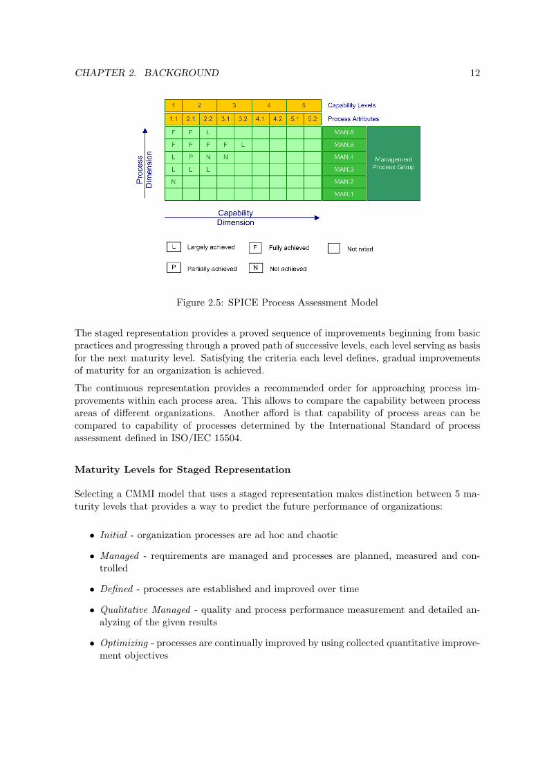
The Process Assessment Model ”forms the basis for the collection of evidence and rating ofprocess capability” [ISO04b]. For this purpose it has a two-dimensional architecture. Thefirst dimension is the Process Dimension, which is characterized by a set of processes entitieswhich purpose statements describe in measurable terms what has to be achieved in order tofulfill the process purpose. The Capability Dimension describes the scale for measuring theefficacy of the process capability in terms of capability levels and process attributes.
Figure 2.5 depicts the architecture wherein process entities of the Process Reference Modelhave been defined in alignment with ISO/IEC 12207. The capability scale is mapped to theSPICE Measurement Framework organized into capability levels and process attributes. Thelevel of achievement of a process attribute is thereby measured by an ordinal rating scale: N- not achieved, P - partially achieved, L - largely achieved, F - fully achieved.
2.3 CMMI Framework
Capability Maturity Model Integration (CMMI) is a framework for assessing and improvingthe capability of organizations development processes.
CMMI bases on the achievements of Capability Maturity Model (CMMI which was developedby SEI (Software Engineering Institute) as response to the needs of the US Department ofDefense (DoD) for better techniques in the selection of contractors. [EDM98]
In 1991 CMM Version 1.0 was officially released for software engineering. Several ProcessModels has been developed during meantime to meet the needs of assessing specific disciplines,e.g. Software Capability Maturity Model (SW-CMM), the Systems Engineering CapabilityMaturity Model (SE-CMM), Integrated Product Development Capability Maturity Model(IPD-CMM) and Supplier Sourcing Capability Model (SS-CMM).
CMMI project was finally formed to sort out the problem of using several Process Models.

CHAPTER 2. BACKGROUND 11
Figure 2.4: Process Entities in ISO/IEC 12207
Its mission was to combine three Process Models into an improvement framework. The latestversion of CMMI, released in year 2002 in version 1.1, combines four Process Models intoa single modular framework. Several integrations are available which are build up from theCapability Maturity Model for Software Engineering: CMMI-SW, CMMI-SE/SW, CMMI-SE/SW/IPPD, CMMI-SE/SW/IPPD/SS. [SEI04]
2.3.1 CMMI Representation for Capability and Maturity
CMM Integration encompasses two representations: Continuous Representation and StagedRepresentation. It depends on the organization’s goal which representation is chosen. Iforganizations want to measure the maturity of their whole engineering process, they willselect the staged representation. If they want to determine process capability in order toselect improvements, they will choose the continuous representation.
CHAPTER 2. BACKGROUND 12
Figure 2.5: SPICE Process Assessment Model
The staged representation provides a proved sequence of improvements beginning from basicpractices and progressing through a proved path of successive levels, each level serving as basisfor the next maturity level. Satisfying the criteria each level defines, gradual improvementsof maturity for an organization is achieved.
The continuous representation provides a recommended order for approaching process im-provements within each process area. This allows to compare the capability between processareas of different organizations. Another afford is that capability of process areas can becompared to capability of processes determined by the International Standard of processassessment defined in ISO/IEC 15504.
Maturity Levels for Staged Representation
Selecting a CMMI model that uses a staged representation makes distinction between 5 ma-turity levels that provides a way to predict the future performance of organizations:
• Initial - organization processes are ad hoc and chaotic
• Managed - requirements are managed and processes are planned, measured and con-trolled
• Defined - processes are established and improved over time
• Qualitative Managed - quality and process performance measurement and detailed an-alyzing of the given results
• Optimizing - processes are continually improved by using collected quantitative improve-ment objectives

CHAPTER 2. BACKGROUND 13
Capability Levels for Continuous Representation
The continuous representation of a selected CMMI model distinguishes between 6 capabilitylevels to describe discrete levels of process improvement:
• Level 0: Incomplete - Process is either not performed or partially performed
• Level 1: Performed - Process is performed and satisfied the specific goals
• Level 2: Managed - A managed process is a performed process that is also planned,monitored, controlled and reviewed
• Level 3: Defined - A defined process is a managed process that is tailored from theorganization’s set of standard processes, and contributes work products, measures, andother process-improvement information to the organizational process assets
• Level 4: Quantitatively Managed - A quantitatively managed process is a defined processthat is controlled using statistical and other quantitative techniques
• Level 5: Optimizing - An optimizing process is a quantitatively managed process thatis changed and adapted to meet relevant current and projected business objectives
2.4 Data Model Structure of ISO/IEC 15504-5 and CMMI
Models related to Software Process Improvement could be the central part of a supportingsoftware tool which guides organizations through process improvement. We need understand-ing of the structure of these SPI related models.
In [LMV02] Lepasaar, Makinen and Varkoi have analyzed the structure of ISO/IEC TR 15504-5 and continuous CMMI. Their work has great impact to an initial data model structure.However, today International Standard ISO/IEC 15504-5 is shortly before publishing. Ithas changed in terminology to the Technical Report and thus we will analyze the newerversions structure. Concerning CMMI, continuous CMMI has a similar approach to SPICEfor selecting improvements. We will not focus on staged CMMI, because it for improving theentire organization.
The logical structure of Process Model concepts and their dependencies can be illustratedwithin an Entity-Relationship-Diagram by means of Entity-Relationship modeling. This mod-eling technique is based upon the Entity-Relationship Model that has been developed by Chen.[Che76] The original notation comes from Chen, but there are a number of notations used,among the more common is Bachman’s crow’s foot. We will use the Bachman-notation.
2.4.1 SPICE Exemplar Assessment Model Structure
ISO/IEC 15504-5 describes an exemplar Process Assessment Model that is compatible to thereference model defined in SPICE Part 2.
This example Process Assessment Model expands the reference model by adding assessmentindicators. Assessment Indicators are ”objective attributes or characteristics of a practice

CHAPTER 2. BACKGROUND 14
or a work product that supports a judgment of the performance or the capability of animplemented process” [EDM98].
Assessment Indicators
ISO/IEC 15504-5 distinguish two types of assessment indicators: Process Performance In-dicator (PPI) and Process Attribute Indicator (PAI). PPI apply solely to ”Capability Level1” and are chosen explicitly to address the achievement of the defined process purpose andoutcomes. Indicator for process performance are Base Practice and Work Product.
Process attribute indicator address practices that provides guidance on the implementationof the attribute achievements, resources that may be used when performing the process andbasic types of work products that may be input to or output from all types of processes.Process attribute indicator are: Generic Practice (GP), Generic Resource (GR) and GenericWork Product (GWP).
Process Dimension
For the process dimension process entities have been adapted from the International Stan-dard for Software Life-Cycle Processes defined in ISO/IEC 12207. This standard defines48 processes covering the discipline of Software Engineering. Each Process is described interms of a Process Name, a Process Purpose and in list of its Process Outcomes. Processoutcomes are expected positive results of its process performance. Additional elements areProcess Notes and Process Identifier.
Life-Cycles provide process grouping into three Process Categories: ”Primary Life-Cycle”,”Supporting Life-Cycle” and ”Organizational Life-Cycle”. Within each life-cycle a secondgrouping into 10 Process Groups is made concerning the type of activity processes address.For example ”Supporting Life-Cycle” is classified into process groups ”Configuration ControlProcess Group” and ”Quality Assurance Process Group”.
The process dimension is extended by a set of Base Practice for each process providingdefinitions of tasks and activities to accomplish the process purpose and fulfill the processoutcomes. Work Product can either appear as input or output to processes. To review inputand outputs of process implementation work products can be characterized by their WorkProduct Characteristics.
Capability Dimension
Evolving process capability is expressed in terms of Process Attributes grouped into 6Capability Levels. These capability levels and their corresponding process attributes havebeen adapted from the Measurement Framework defined in ISO/IEC 15504-2.
Each process attribute has a set of associated process attribute indicators to indicate the ex-tend of achievement of the process attribute in the instantiated process: Generic Resourceand Generic Work Product apply directly to process attributes. Generic Practice pro-vide guidance on the implementation of Process Attributes Achievements. Generic work
CHAPTER 2. BACKGROUND 15
products are characterized by a set of Generic Work Product Characteristic that wouldbe expected to be evident for work products.
Certain processes relate to the capabilities addressed by a process attribute and evidence oftheir performance support achievement of the attribute.
SPICE Data Model
Following concepts become entity types: Life-Cycle Process Category, Process Group,Process, Base Practice, Work Product, Work Product Characteristics, Capability Level,Generic Resource, Generic Work Product, Generic Practice, Generic Work Product Char-acteristic, Process Outcome, Process Attribute, Process Attribute Achievement.
Concepts of Process Purpose, Process Note, Process Name and Process Identifier be-come attributes of entity type Process.
The concepts of Assessment Indicator, Process Performance Indicator and ProcessAttribute Indicator do not need necessarily become entity types. They provide just group-ing facility.
Relationships represent associations between these entities. Relationship names are not rep-resented within the model, instead, role names are denoted. Sometimes it is not obvious inwhich relation an entity stands to another. Then we denote a role name to the entity in therelation.
Entity attributes which have not been stated in the previous paragraphs are retrieved fromthe Process Assessment Model documentation in [ISO04d].
According to the given information, an entire conceptional data model has been created. Itis illustrated in figure 2.6.
2.4.2 CMMI Structure
Capability Maturity Model Integration is a framework that provides guidance to implement aneffective process based on a selected Process Reference Model. The continuous representationfollows a similar approach to SPICE in the area of capability determination. The stagedrepresentation focuses on capability of the entire organization measuring its maturity.
Model Components
CMMI components are grouped into three categories:
• Required: Generic Goals and Specific Goals define required achievements to satisfy thecorresponding process area. These components must be achieved by an organizationplanned and implemented process.
• Expected: Expected achievements are defined by Generic Practices and Specific Prac-tices. They describe what an organization will typically implement to achieve a requiredachievement.

CHAPTER 2. BACKGROUND 16
Figure 2.6: ISO/IEC 15504-5 conceptional data model
• Informative: Subpractices, Typical Work Products, Discipline Amplifications, GenericPractice Elaborations, Goal Titles and Practice Titles, Goal Notes and Practice Notes,and References are informative model components that help model users understandthe goals and practices and how they can be achieved.
Continuous Representation
The continuous representation uses 6 Capability Levels to indicate improvement evolu-tion for each of the Process Area organized by 4 Process Area Categories, for example”Project Management” or ”Engineering”.
Specific Goals apply to process areas to address a unique characteristic that describes whatneeds to be implemented to satisfy the process area. Specific Practices are grouped tospecific goals that collectively describe the activities to achieve the associated goal. As itis pictured in figure 2.7 these specific practices are mapped to capability levels. Specificpractices at capability level 1 address Base Practices and specific practices at higher levels

CHAPTER 2. BACKGROUND 17
are called Advanced Practices. Advanced practices may build on a base practice, but it isnot necessary.
Each capability level has one Generic Goal that describes what an organization has to achieveat that capability level. Generic Practices are the required model components that describethe activities to achieve the generic goals. Generic practices apply to just one generic goal.
A Typical Work Product provides example output from specific or generic practices. Sub-practices provide guidance for performing specific and generic practices.
Discipline Amplifications are informative components that contain information to spe-cific practices relating to a particular discipline.
Generic Practice Elaborations provides guidance on how generic practices should be ap-plied to one certain process area.
Figure 2.7: CMMI continuous representation
CMMI Data Model
The entity-relationship model illustrated in [LMV02] is modified concerning the fact thatwe want to track the practices which have impact on the process performance. They arecalled base practices. They are directly applied to specific goals. Advanced practices are alsoassociated to specific goals. Both concepts are generalized into specific practice. From therewe can figure out to which capability level a specific practice belongs.
Specific practice and generic practice are generalized by practice, because subpractice canapply to generic and specific practice.
The entire data model is depicted within figure 2.8.
2.5 Knowledge about Software Process Improvement
After process assessment has been performed improvement actions are prioritized. Theseimprovement actions ”consist of good software engineering practices, however, defined as ab-stract, high-level concepts without constraining the ways in which they may be implemented.The criteria are the set of attributes that might be found in an instantiation of a process”[EDM98].

CHAPTER 2. BACKGROUND 18
Figure 2.8: CMMI conceptional data model
Guidance how to implement improvements is more important after assessment. So far externalconsultants have been supported improvement activities by their knowledge and experienceabout Software Process Improvement implementation. This knowledge comes from morepractical models that give guidance for implementation. For example Extreme Programmingis software development methodology that turns project faster into success. Basically it baseson 13 practices covering good practices that have great impact on software quality and projecttime. They are described in their practice and their benefit. Implementing these practicescould contribute to process improvement. This is what we mean by knowledge.
Knowledge in general meaning is defined in [WIK05c] as ”the awareness and understandingof facts, truths or information gained in the form of experience or learning, or through intro-spection”. But knowledge is ”neither data nor information. Knowledge is distinct from simpleinformation. Both knowledge and information consist of true statements, but knowledge isinformation that has a purpose or use. It is information with intention” [WdHvdS97].
We limit discussion to experience needed for Software Process Improvement implementation.This is why we are talking about SPI Knowledge.

CHAPTER 2. BACKGROUND 19
Knowledge Item
Knowledge Items are the smallest pieces of experience that can be created, stored and shared.When we talk about knowledge items we usually mean individuals within the class of know-ledge.
Based on the experience of Gnosis knowledge base, that has been evaluated in section 3.1,a possible structure for knowledge items can be adapted and reused. Any knowledge itemincluded in Gnosis owns following structure:
• Title - name of this knowledge item
• Problem - what problem is addressed by this item
• Purpose - what is the purpose
• Description - a detailed description
• Examples - useful examples
• Solution - what is the proposed solution
• Risks - what are the risks
• References and Links - references to other documents
• Resource Requirements - which resources are additional needed
• Author - the author of this item
• Applicability - to which organizations this knowledge is applicable
• Introduction - brief description
• Related Knowledge - items that are subsequently related
Knowledge Context
A Knowledge Context is a domain to which knowledge items provide benefit. A knowledgecontext is a kind of higher-level domain to which a couple of knowledge items provide im-plementation help. A knowledge item can have at least one context, but it does not neednecessarily have one. In this case, it is related to another knowledge item that providesbenefit to a certain context.
For example, we could add a knowledge item that includes experience about good defectclassification. It might be called ”Classification of defects and errors”. It could be in contextto ”System Testing” or ”Software Component Testing” or ”Testing” in general.
Another example comes from Extreme Programming. XP is an software engineering methodthat is based on 13 practices. Any practice is related to a knowledge item that states aboutan ”Agile Software Development”. Any of these base practice is related to this item. However,not any practice has a context. There is a practice called ”Metaphor” for which no propercontext could be found. But in contrast practice ”40h Week for Software Engineers” could becontext to ”People Workpace” and ”Project Planning”.

CHAPTER 2. BACKGROUND 20
Knowledge Type
Another attribute for knowledge that supports SPI is its type. A Knowledge Type indicatesthe naturally form of an knowledge item. For example, if we had a knowledge item thatsupplies making a project plan by a template, it might be therefore of the type ”template”.
Following list of types might possible:
• Good Practice - practice that helps to achieve a specific goal (sometimes known as bestpractice)
• Theorem - statement that has been proved by someone
• Template - a sheet of a special pattern
• Information - facts about an area of interest
• Guidance - gives help or advise to perform a task
• Paradigm - example that shows how something works or is produced
2.6 Vision of the Semantic Web
Semantic Web is for the time a buzzword that is more and more mentioned when expertsdiscuss about the Internet of the future.
The word semantic implies meaning or, as the DUDEN4 defines it, ”study of the meaning ofspeech symbols”. For the Semantic Web, semantic indicates that the meaning of data on theWeb can be discovered - not just by people, but also by computers.
The vision behind Semantic Web is ”the World Wide Web becomes a giant database, linkingboth human readable documents and machine readable data in a way useful for mankind andmachine” [BL03].
Currently the World Wide Web consists of textural files that are evaluated just for displayingpurposes. Information and knowledge are encapsulated within Hyper Text Markup Language(HTML) or Hyper Text Markup Language (XML) tags used for information displaying orstructuring.
Until now just humans can make accessible the sense of documents, but the idea of SemanticWeb is to give data more meaning through the use of meta-data, the data about data, thatdescribes how, when and by whom a particular set of data was collected. By adding meta-datato existing Web, the Semantic Web will allow both humans and machines to find and makein ways that previously haven’t been possible. Actually the benefit of the Semantic Web isfor machines. They become able to discover and to extract desired information from Webresources. [BL03]
But how machines can do, how humans have ever could? Berners-Lee refers in [BL04] thatthe Semantic Web uses two different approaches: A common readable data format and a well
4German standard book for grammar

CHAPTER 2. BACKGROUND 21
defined ontology. The former one addresses a standardized machine readable format that baseon standards XML, Resource Description Framework (RDF) and on the top of them the WebOntology Language (OWL).
”The father” of the Semantic Web initiative, Berners-Lee, has considered in [BL00] the archi-tecture that is sometimes called ”Semantic Web layer cake” depicted in figure 2.9 because ofits stack view on languages.
Figure 2.9: Layers of Semantic Web pyramid
The layers are explained as follows:
• Unicode - Character encoding format
• URI - Unified Resource Identifier. URI provides a common syntax for naming resources
• XML - Language for structuring informations. Standard data exchange format.
• XML Schema - Language used to describe the structure of specific XML languages
• RDF - Resource Description Framework. Its data-model describes meta-data of re-sources
• RDF Schema - Language for describing schemes in terms of classes and properties.Allows to design simply ontologies.
• OWL - Web Ontology Language. More complex and expressible language for ontologies.
• Logic - Logical reasoning ensures the consistency and correctness of data sets and infersconclusions that aren’t explicitly stated
• Proof - Trace the steps of logical reasoning
• Trust - Authentication and trustworthiness of data, services and agents
The sections following deal with underlaying techniques that allows to state informations intoontologies. In particular we lay discussion on RDF that provides the fundamental data-model,RDF Schema describing an ontology vocabulary and OWL is for more expressive ontologies.

CHAPTER 2. BACKGROUND 22
2.6.1 Resource Description Framework
The World Wide Web Consortium (W3C) has been developed the Resource DescriptionFramework (RDF) as a key component of its vision for a Semantic Web. RDF is a lan-guage for representing information about resources in the World Wide Web. It was especiallydesigned to provide meta-data about Web resources. [MM04]
RDF Data-Model
RDF uses a simple data-model to structure information about resources in the form of State-ments. An RDF statement is equivalent to English Grammar that is also being built of thesedifferent parts:
• Subject - Resource about is made this statement
• Predicate - Property of the subject
• Object - Property value. Can be either a resource, a literal or a blank node
Because of the three parts structure a statement is called a Triple. A triple is the smallestpiece of knowledge that is human readable as well as machine readable.
Figure 2.10: Graphical representation of a RDF statement
The parts of a statement - subject, predicate and object - are described by resources namesURI references. An object is not a resource at all. Objects can be either a resource addressedby URI references, a Literal or a Blank Node. Literals are a characters representation ofthe object value. Blank Nodes are anonymous resources which are not denoted by an URI.There are some applications that make up their own identifier for blank nodes, but in naturalmanner they are left. Blank nodes are particular used for aggregating things to be describedas resource and then making statements about the resource. They act thereby as group offacts.
An URI references is an identifier for resources. It contains a prefix, which corresponds to anamespace, following by a colon and a local name. The last part is also denoted as fragmentidentifier. A fragment identifier is optional and may be only used to identify resources.
The structure of a URL reference is:
URL Reference = URI [fragment identifier]fragment identifier = ’#’ local-name
The prefix refers to the term of Unified Resource Identifier (URI). The Network WorkingGroup describes a URI in [BL+98] as ”compact string of characters for identifying an abstractor a physical resource”.

CHAPTER 2. BACKGROUND 23
A URI can refer to a location as well to a name. URI are related to URL (Uniform ResourceLocater) in that URL is a subset of URI of an URL scheme based on a known protocol (e.g.HTTP or FTP protocol). URI references from a specific domain form thereby a collectionthat is called a vocabulary.
Examples of URI, URI references and URL:
http://www.debian.org/intro/about.html - URL or URIhttp://www.w3.org/1999/02/22-rdf-syntax-ns#Class - URI referencethis.is.just.a.name - URI
XML Serialization of Statements
XML is a widely used data exchange format that can be processed by XML Parsers. It allowsto encode RDF statements into XML files that is known as rdf-xml serialization. In the matterof representing the RDF data model into XML, the RDF Syntax Recommendation [Bec04]provides a XML vocabulary to transform RDF statements into XML terms.
1 <?xml version="1.0"?><rdf:RDF
3 xmlns:rdf="http://www.w3.org /1999/02/22 -rdf -syntax -ns#"xmlns:dc="http://purl.org/dc/elements /1.1/">
5 <rdf:Description rdf:about="http: //www.hornet -home.de"><dc:Title >Honda Hornet Homepage </dc:Title >
7 <dc:Creator >Andre Frenzel </dc:Creator ><dc:Description >Largest community for Honda Hornet Drivers in
Germany.</dc:Description >9 </rdf:Description >
</rdf:RDF >
Listing 2.1: RDF statements transformed into XML
2.6.2 Ontologies
Ontologies play a key role in the terminology of the Semantic Web. There are many definitionsin literature about what an ontology is. John Davies defines in [DFvH03] ontologies asa ”shared and common understanding of a domain of interest that can be communicatedbetween people and application systems”.
The term ontology comes thereby from the philosophy and means the study of ”being” orexistence trying to find out what entities and what types exist. In computer science, themeaning for ontology has derived from the philosophy and it is defined in [WIK05d] as ”formalsystem of concepts, describing all the relevant entities, their relationships and the rules withinthe domain of interest”.
Ontologies can be expressed by ontology representation languages. The next section introducetwo languages for describing ontologies.

CHAPTER 2. BACKGROUND 24
2.6.3 RDF Schema
RDF vocabulary description language (RDF Schema or RDFS) is the base language for de-scribing ontologies. It bases on the top of RDF and it is intended to use for limited andinexpressive ontologies. [Zie03]
RDFS is an semantic extension to RDF to specify domain specific vocabulary and objectstructures. It provides mechanisms for describing groups of related resources and the rela-tionships between these resources. [BG04]
In other words, RDFS provides meta-model functionality to describe areas of interest as itXML Schema does, however, not on the syntax level, rather than on the semantic level.
Within the next sections the basic features of RDFS are introduced.
Classes
A significant feature that RDFS provides is to group resources into Classes. Classes are”concrete representation of concepts” [Hor04]. They are declared using property rdfs:Class.
Classes are typically arranged into class hierarchy which is also known as Taxonomy. RDFSprovides the property rdfs:subClassOf to make statements about classes that are sub-classesof another.
Consider the example of printers in order to introduce the concept of classes and sub-classes.The statements below create a class hierarchy of several kind of printers. The class of Printeris the most general concept. LaserPrinter, MatrixPrinter and InkJetPrinter are more specificclasses because of their different printing technique. They apply as subclasses to class Printer.The concept of InkJetPrinter is further divided into BubbleJetPrinter and PiezoJetPrinter.The resulting hierarchy is pictured in figure 2.11.
<rdfs:Class rdf:ID="BubbleJetPrinter"><rdfs:subClassOf rdf:ID="InkJetPrinter"/>
</rdfs:Class ><rdfs:Class rdf:ID="InkJetPrinter">
<rdfs:subClassOf rdf:ID="Printer"/></rdfs:Class ><rdfs:Class rdf:ID="LaserPrinter">
<rdfs:subClassOf rdf:resource="Printer"/></rdfs:Class ><rdfs:Class rdf:ID="MatrixPrinter">
<rdfs:subClassOf rdf:ID="Printer"/></rdfs:Class ><rdfs:Class rdf:ID="PiezoJetPrinter">
<rdfs:subClassOf rdf:ID="InkJetPrinter"/></rdfs:Class ><rdfs:Class rdf:ID="Printer">
<rdfs:subClassOf rdf:resource="Resource"/></rdfs:Class >
Listing 2.2: Defining a superclass-subclass hierarchy

CHAPTER 2. BACKGROUND 25
Figure 2.11: Simple class hierarchy
Instances
An Instance represents an object if it applies to a class. We also say an instance is a memberof a class. Resources must be typed by RDF property rdf:type to that class to which it isinstance.
Properties
RDFS defines the concept of Properties. Properties, that are denoted by rdfs:Property, arerelations on subject resources and object resources.
Properties can be arranged into property hierarchies in the same way as it is done for classes.The related property is called rdfs:SubPropertyOf.
Consider the following example: b rdfs:SubPropertyOf a. The meaning of the semantic levelis that all pairs of resources that relate to property a also relate to sub-property b.
<rdfs:Property rdf:ID="b"><rdfs:SubPropertyOf rdf:ID="a">
</rdfs:Property >
Listing 2.3: Defining a property hierarchy
Properties can state about its domain (rdfs:domain) and its range (rdfs:range). In state-ments where its predicate is a property, a subject resource must satisfy the domain and anobject value the range. This means a subject resource must be a class or a sub-class to whichthe domain is set. Object values must be instance of the class, or its sub-class, the range isset to.
<rdfs:Property rdf:ID="a"><rdfs:domain rdf:ID="A"><rdfs:range rdf:ID="C">
</rdfs:Property >
Listing 2.4: Defining the range and the domain of a property

CHAPTER 2. BACKGROUND 26
2.6.4 Web Ontology Language
The fundamental language for representing semantic facts is called Web Ontology Language(OWL) that is currently a recommendation of the Word Wide Web Consortium (W3C).[B+04]
OWL facilitates greater machine interpretable of Web content than that supported by XML,RDF, and RDF Schema. OWL builds on the top of RDF Schema. Thus, it has all thecapabilities RDFS has, but it provides a couple of new facilities. Some of new features areintroduced in the following.
Species of OWL languages
OWL comes with three sub-languages:
• OWL Lite - provides simple class hierarchies and simple constraints
• OWL DL - includes all OWL Lite languages constructs and add additionally constructsfor restrictions, but the language remains decidable and computable. OWL DL corre-sponds to the field of Description Logics which deals with decidable fragments of theFirst Order Logic.
• OWL Full - supports the full specification of OWL constructs. However, there is noguaranty that computation stops in finite time
Changes to RDFS
However, there are slightly different syntax representing classes and individuals. In OWLclasses are denoted by owl:Class. Each user-defined class is implicit a sub-class of owl:Thing.
In RDFS the concepts of properties have been launched. Properties let us assert facts aboutmember of classes. OWL split properties into two different types:
• owl:DatatypeProperty - relations between instances of classes and RDF literals orXML datatypes
• owl:ObjectProperty - relations between instances of two classes.
Property Restrictions
Within the context of owl:Restriction, restrictions can be applied on range and domainof properties using OWL construct owl:onProperty. Restrictions fall into three categories:Quantifier Restriction, Cardinality Restriction and hasValue-Restriction.
Quantifier Restrictions limit which values can be used. They exist in two alternatives:
• owl:allValuesFrom - a particular class may have a restriction on a property in suchevery instance has only values from a certain type. This is also known as universalquantifier.

CHAPTER 2. BACKGROUND 27
• owl:someValuesFrom - a particular class may have a restriction on a property suchevery instance member of that class has at least one value of a certain type. Alsonamed existential quantifier
Cardinally Restrictions limit the number of values on this property on instances of that class.They exist also in two alternatives: owl:minCardinality and owl:maxCardinality that refer tothe upper and lower limit.
Last but not least, HasValue-Restriction require to a property to have a certain individual asits value.
Equality and Inequality
We can state about two classes being equivalent owl:equivalentClass. Equivalent classeshave the same individuals and are therefore called Synonymous Classes.
Look at figure 2.12. Both classes ColourPrinter and ScannerPrinterCombination are sub-classes of Printer, but they are red colored. That means they are equivalent classes to mostlynot named classes5. These unnamed classes are restricted on property isColourPrinter andon property hasScannerFacility respectively to a given value. Any individual that satisfy thiscondition is member of this class. By means of Reasoning these individuals can be deducted.
Figure 2.12: Synonymous classes created with a hasValue-Restriction
Boolean Expressions
Boolean combinations help to define arbitrary classes and restrictions: unionOf, comple-mentOf, intersectionOf. Consider the example before, we could have constituted a classwhich intersects classes LaserPrinter and ColourPrinter to a new class of ColourLaserPrinter.
5within RDF Graph these classes become blank nodes

Chapter 3
Related Work
There has been interesting work done concerning development Software Process Improvementrelated software tools. One attempt has been given by FiSMA1. We take a closer look at oneof the achievements by FiSMA.
3.1 GNOSIS - a Knowledge Base for Software Process Im-provement
Finland has been established as one of the leader in Software Process Improvement.Hightechfinland.com describes the role of continuous Software Process Improvement. Toprovide advice and share experience in the field of Software Process Improvement FiSMA hasbeen founded in 1998.
FiSMA is a network about 40 member organizations. Their activities cover guiding devel-opment of the estimation tools and experience database, guiding support and developmentof the method based on ISO 15504 standard, meetings and seminars for the members aboutsoftware measurement topics, participation in ISO standardization in the software processand measurement areas.
One of the out-coming tools released by FiSMA was a knowledge base known as Gnosisfor primarily support of internal assessments and SPI planning activities. However, Gnosisknowledge base is still in prototypical state and not for being thought for production use.
Gnosis implements a common set of best practices and company specific knowledge for contextspecific SPI needs denoted as knowledge items within the system. This knowledge has beenlinked to those processes, concepts and practices of Process Reference Models CMMI-SW andISO/IEC 15504 that needs to be given supplementary information e.g. for guidance.
Within the next sections the basic possibilities of Gnosis is introduced and finally discussedand rated.
1Finnish Software Measurement Association
28

CHAPTER 3. RELATED WORK 29
3.1.1 User Interface
The Gnosis Knowledge Base is a Web application and therefore can be easily accessed by anyInternet Browser.
First of all user and password are requested for getting authorized by the system. Afterauthentication has been succeeded, the user is forwarded to the welcome page that is ac-tually the SEARCH Web page. Furthermore there are three other Web pages: BROWSE,MAINTENANCE and GRAPH.
SEARCH Web page
At this page a keyword based search facility is offered. Gnosis serves a list of items as result.This list is ordered by the calculated strength coefficient. The strength coefficient describesthe relationship’s relative importance.
Items are not only picked in the result because of the name includes the keyword, also relateditems are put in the result. This is why the strength coefficient is important.
Items which are found are denoted by different kind of circles or by their type respectively.Particular knowledge items are emphasized by a green colored sign that makes user easier tosee interesting items at the first glance.
Figure 3.1: Gnosis’ search result
BROWSE Web page
The browsing functionality enables the user to access all the Process Model elements andknowledge items within a Java applet depicted in figure 3.2. Reading the data from the Javaapplet takes up to 45 seconds also by using a fast Internet connection.

CHAPTER 3. RELATED WORK 30
Figure 3.2: Gnosis’ browsing applet
The applet enables the user to group data by a certain style: type grouping, none grouping,level grouping, level-type grouping, model grouping.
Within the applet a search operation is offered which directly operates on the tree. After akeyword is entered not matching items are immediately skipped.
By selecting a certain item from the tree a detailed description is displayed 3.3.
MAINTENANCE Web page
At this Web page the user can maintain all the items defined in Gnosis, in particular goals,impacts, concepts, knowledge items. These items can be edited by a WYSIWYG HTMLeditor that comes as 3rd party applet pictured in figure 3.4.
GRAPH Web page
Within the Java applet relations of connected items are graphically represented. Differentcolors are used to indicate the different categories. The initial graph is computed by a depth

CHAPTER 3. RELATED WORK 31
Figure 3.3: Gnosis’ knowledge item view
of two. This means, counting the edges starting from the selected item is two. However, theresulting graph is sometimes full of connections and items depicted in figure 3.5.
3.1.2 Data-Model Structure
Gnosis distinguishes data between seven several categories:
• CMMI Specific Practices - base practices from CMMI Process Model
• SPICE Base Practices - base practices from SPICE Process Model
• Concepts - further CMMI and SPICE Process Model elements
• Goals - serve as reference points to elements which attain the goal
• Impacts - serve as reference points to elements which have impact
• Knowledge Items - good practices or specific knowledge
• Processes - processes which either belong to CMMI or SPICE Process Model
The structure of these items is as follows:

CHAPTER 3. RELATED WORK 32
Figure 3.4: Gnosis’ maintenance page
structure(dataItem) = (title(dataItem), properties(dataItem), relatedItems(dataItem))properties(dataItem) = (attribute, value)*
relatedItems(dataItem) = (link(relatedItem), type, strength*)type = has-a | supports | overlaps | helps | see also | associationstrength = strong | medium | weak
The basic type of a relation is indicated by property type. Relationship of type ”has-a” ismost frequently used.
The strength-property denotes the impact of related items to the relationship. A strongrelation means there is a high impact on the item, while a weak relation means there is justa low impact on the related item.
3.1.3 Evaluation
Although Gnosis is in prototypical state its shortcomings in concept, usability and stabilitydo not make it well suited for professional use. Its user interface responds slow because ofJava Applets. Session time-out and internal exception messages forwarded to the user are userunfriendly. Gnosis has not been designed to adapt further Process Models. Its architectureis restricted to concepts from SPICE and CMMI.
We shortly discuss and classify any issue concerning conception, usability and stability.

CHAPTER 3. RELATED WORK 33
Figure 3.5: Gnosis’ graphical view on relationships
Conceptual Issues
item to item linking Relations are established by one to one mapping. Knowledge itemswhich are added to the knowledge base must be manually connected to related items.Managing the knowledge base means that a maintainer needs also skills in field ofProcess Models to apply the knowledge to the right concepts.
no distinction of concepts Gnosis unionizes several concepts like Process Category, WorkProduct, Process Attribute into a single category Concept. However, these conceptsare unlike each other. They distinguish in their meaning and in their of structure.
fixed relationship types drive into loss of information Relations among items are de-noted by a fixed identifier. Model items are connected by relationship type ”has-a”.However, sometimes their meaning is more than ”has something”. For example, relation-ship between elements from category Process Category and elements from categoryProcess could be more meaningful denoted by type has-Process.
Usability Issues
use of client-side Java applets Use of Java applets is almost reserved for interactive ap-plications. They have negative impact on the performance of Web-applications. Beforeapplets can be used in Web pages, the Java Virtual Machine needs initialized before.This takes time and a lot of memory capacity.
slowly data-model reading Although the user has a fast Internet connection reading thedata-model takes a couple of time caused by the transfer of data to the applet. Evenby DSL connection Gnosis need up to 60 seconds.

CHAPTER 3. RELATED WORK 34
Stability Issues
out of session After a short period of time (about 15 min) while inactivity session is gettinglost. The session period is to short to seriously work with Gnosis. However, this can befixed setting a higher value to the session time-out.
no exception handling There is no exception handling implemented when the applicationcrashes. Therefore, the user is confronted with an incomprehensible exception message.One of the design goals of good software is to prepare meaningful error messages to theuser.

Chapter 4
Proposed Solution
This chapter suggest an architecture that refers to provide effective support for SoftwareProcess Improvement within a software tool.
One of the system’s design goal is, the database is not fixed on the structure for a number ofProcess Models. This means, Process Model’s structures might differ in their concepts andtheir relations among the concepts. As we have pointed out in section 2.4 the data model ofSPICE and CMMI is not similar. But, if we identify a generic Process Model that provides ageneralization about the concepts and relations, we could implement its data structure into a(relational or object-oriented) database. However, a database is ”a collection of information[...] that can be managed and queried by a database management system” [WIK05a], butthere is no system that provides meta-data about the database concepts.
Ontologies are like databases. The structure (schema) and the content (data) form a database.If we think of the schema and the data, then the ontology becomes a meta-model. In section4.1 and in the following we discuss this meta-model approach concerning a database schemamapping into an ontology.
There are two alternatives how we could Process Models bring into a single data schema. Ei-ther by developing a generic Process Model or by integrating the structure of several ProcessModels. The first option is discussed in section 4.1.2. However, it has been shown transfor-mation into a generic model comes with loss of model specific features. Therefore, we advisein section 4.1.3 to develop by a single data schema that is based upon an integration approachfor several sub data models that are mapped into an ontology meta-model.
As well as ontologies can be used for describing a schemata, they are ”formal defined systemsof terms and/or concepts and relations among them to represent knowledge in the domainof discourse” [WIK05d]. The domain of discourse is here knowledge about Software ProcessImprovement. By an iterative approach we show in section 4.2 how SPI Knowledge could besuccessive transformed into a simply ontology, called taxonomy, that provides classification forthe knowledge objects. Afterward we discuss classes as ”sets of individuals that are collectedtogether for the purpose of classification”[Pas04] according to provide a finer granular ontologyof SPI Knowledge.
From the Semantic Web comes the possibility ”to allowing ontologies to be related, includingexplicitly importing information from other ontologies” [S+04]. We show in section 4.3 how we
35

CHAPTER 4. PROPOSED SOLUTION 36
can use the import feature from Web Ontology Language to accomplish knowledge transition.As we have figured out in section 3.1 knowledge items could be one to one mapped to modelitems requires knowledge about Process Models. We introduce and propose another way ofknowledge transition can happen by means of ”virtual knowledge linking”.
Ontologies provide the schema and the data about Process Models and SPI Knowledge. How-ever, they do not contain information about a proper navigation through each Process Model.By attaching annotations to existing ontologies, without changing them, we can supply in-formation for a software tool. This OWL meta-data construct is originally used to provideadditionally comments on classes, properties and individuals. How we are going to reuse itfor presentation purpose is described in section 4.4.
4.1 Ontology-based Meta-Model
In [LMV02] it has been suggested by Lepasaar, Makinen and Varkoi in their conclusion to”integrate the structure of SPICE and CMMI and later on, to develop a meta-model thatgeneralizes the Process Model structure of SPICE and CMMI”. Additional information havenot been given about what is meant by structural integration and generalizing the structureof CMMI and SPICE into a meta-model.
Johannes Ernst defines in [Ern03] a meta-model as ”an explicit model of the constructs andrules needed to build specific models within a domain of interest”. With other words, a meta-model describes the methods of a model that represents a cutout from the real world. If wehad such a meta-model, we could make statements about the methods the underlaying modeldescribes the real world.
4.1.1 Mapping Database Schemes into Ontologies
As we have seen in section 2.6.4 ontologies can be expressed by Web Ontology Language.OWL has a grammar that can describe things in ontologies in its terms of classes, propertiesand individuals.
OWL capabilities work also for expressing database schemes. A database schema can be splitinto table definitions (the corresponds to the schema) and a data dictionary, that contains thedata. The relations between data in database schemes can be represented by data models.[Pas04]
If we describe a database schema, by its schema and data, by means of Web Ontology Lan-guage into an ontology, then the resulting ontology constitutes a meta-model for the schema.
Database schemes are graphical representations of concepts and their relationships. For exam-ple, the Entity-Relationship Model is ”a data model for high-level descriptions of conceptionaldata schemes” [WIK05b]. Consider the fact, we can transfer database schemes into an on-tology, therefore we can transfer Entity-Relationship Models into an ontology, too. We willprovide a mapping from the terms used in the Entity-Relationship-Model to the languagesconstructs defined in OWL. This mapping is depicted in figure 4.1.
• Entity Types - Each entity type in the data model becomes a class within the ontology
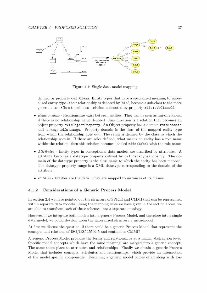
CHAPTER 4. PROPOSED SOLUTION 37
Figure 4.1: Single data model mapping
defined by property owl:Class. Entity types that have a specialized meaning to gener-alized entity type - their relationship is denoted by ”is a”, become a sub-class to the moregeneral class. Class to sub-class relation is denoted by property rdfs:subClassOf.
• Relationships - Relationships exist between entities. They can be seen as uni-directionalif there is no relationship name denoted. Any direction is a relation that becomes anobject property owl:ObjectProperty. An Object property has a domain rdfs:domainand a range rdfs:range. Property domain is the class of the mapped entity typefrom which the relationship goes out. The range is defined by the class to which therelationship goes in. If there are roles defined, what means an entity has a role namewithin the relation, then this relation becomes labeled rdfs:label with the role name.
• Attributes - Entity types in conceptional data models are described by attributes. Aattribute becomes a datatype property defined by owl:DatatypeProperty. The do-main of the datatype property is the class name to which the entity has been mapped.The datatype property range is a XML datatype corresponding to the domain of theattribute.
• Entities - Entities are the data. They are mapped to instances of its classes.
4.1.2 Considerations of a Generic Process Model
In section 2.4 we have pointed out the structure of SPICE and CMMI that can be representedwithin separate data models. Using the mapping rules we have given in the section above, weare able to transform each of these schemes into a separate ontology.
However, if we integrate both models into a generic Process Model, and therefore into a singledata model, we could develop upon the generalized structure a meta-model.
At first we discuss the question, if there could be a generic Process Model that represents theconcepts and relations of ISO/IEC 15504-5 and continuous CMMI?
A generic Process Model provides the terms and relationships at a higher abstraction level.Specific model concepts which have the same meaning, are merged into a generic concept.The same takes place to attributes and relationships. Finally we obtain a generic ProcessModel that includes concepts, attributes and relationships, which provide an intersectionof the model specific components. Designing a generic model comes often along with loss

CHAPTER 4. PROPOSED SOLUTION 38
ISO/IEC 15504-5 concepts CMMI conceptsLife-Cycle Process Category -Process Group Process CategoryProcess Process AreaProcess Outcome Specific GoalBase Practice Base Practice (subset of Specific Practice)Work Product Typical Work ProductWork Product Characteristic -Capability Level Capability LevelProcess Attribute -Process Attribute Achievement Generic GoalGeneric Practice Generic PracticeGeneric Work Product -Generic Work Product Characteristic -Generic Resource -- Generic Practice Elaboration
Table 4.2: Concepts of ISO/IEC 15504-5 and their counterpart in CMMI
of information of specific model features. Because it provides an intersection of commonconcepts, model specific features were cut off from the generic model. This makes just sense,if the specific models have similar concepts and provide relations that is shared among anyspecific model.
Valuable preparation work concerning the structure has been already done in 2.4. We startby comparing the concepts of SPICE and CMMI. Table 4.2 faces the concepts and theirmodel counterparts. Within the process dimension CMMI has a hierarchical structure amongProcess, Specific Goal, Specific Practice and Typical Work Product. In SPICE concepts ofBase Practice, Work Product and Process Outcomes are parallel elements. There are norelations that document a Base Practice accomplish a Process Outcome and a Work Productis output of a Base Practice.
In SPICE Capability Levels are characterized by Process Attributes. There is no counterpartgrouping mechanism in CMMI. Generic Goals apply directly on Capability Levels and SpecificPractices are mapped to Capability Levels for a given Process Area.
Within the process and capability dimension both models have similar concepts, that some-times differ just in names. A couple of concepts are additional to SPICE and others to CMMI.However, relations among concepts are slightly different. CMMI forms a hierarchical processdimension, SPICE only to a certain degree. There could be a generic model, but it is lim-ited, because CMMI or SPICE define some relationships that are not denoted in their modelcounterparts. Actually generic models make sense, if their specific models differ only in minormatters.

CHAPTER 4. PROPOSED SOLUTION 39
4.1.3 Integration Approach for a General Process Model Structure
The previous section has focused on a generic Process Model that is based upon a singledatabase schema. Unfortunately, there does not exist a generic database schema that couldbe mapped into an ontology.
Another way to integrate Process Models is to find a generalization that preserves the conceptsand relationships within a single data model. We call this approach Process Model Integrationinto a general Process Model.
Figure 4.2 depicts the solution. Each data model is integrated as kind of sub data modelwithin a single data model. We include abstract entity types into the general data model thatare termed to the domain name of its sub data model, and it is connected to each sub entitytype. We include another abstract entity type that generalizes the previous added entitytypes. This entity type is denoted by a name concerning to the domain of the entire datamodel.
Figure 4.2: Multiple data model mapping
4.1.4 Mapping the General Process Model into an Ontology
Applying the method that we have described in the previous paragraph, we become ableto transform any Process Model’s database schema into a single schema and finally into anontology. This transformation is done without losing model related features.
We have concerned with a data model for ISO/IEC 15504-5 and continuous CMMI in section2.4. We provide by example a mapping of these data models. The resulting class hierarchyfor both models is depicted in the appendix in figure A.1.
Step 1: Renaming Entity Types and Relationships If entity types, relationships andattributes have equal names, they have to be renamed to get a unique identifier. For exampleSPICE and CMMI include entity type Capability Level or Base Practice. In order topreserve the names, we add prefix ”SPICE-” to entity and relationship names of SPICE andto entity and relationship names of CMMI we add ”CMMI-”.

CHAPTER 4. PROPOSED SOLUTION 40
Step 2: Entity Type to Class Mapping Any entity-type within the data model becomesan ontology class. We additionally create classes for each Process Model that has beenincluded : SPICE and CMMI. The scope of the resulting ontology is also represent as a uniqueclass called Process-Model.
Step 3: Arranging the classes within a class hierarchy Classes of SPICE and CMMIbecome sub-classes of Process-Model. Process model specific classes specialize its corre-sponding general class and become therefore sub-class of them. For example, any class namethat begins with ”SPICE-” becomes sub-class to SPICE and so on. If there are more classsub-class relations, they become arranged within the class hierarchy. This applies for in-stance to CMMI-BasePractice or CMMI-AdvancedPractice which become sub-class to CMMI-SpecificPractice.
Step 4: Relationship to ObjectProperty Mapping Within the data model relation-ships are not denoted by a relationship name. Instead, role names are denoted at relationshipends, but not anywhere. Relationships are bi-directional, therefore any direction becomes anobject property termed as follows: ”Has-” + Name of the Class. For example, the relationfrom SPICE-ProcessGroup to SPICE-Process is termed to Has-SPICE-Process. The oppo-site direction is termed to Has-SPICE-ProcessGroup. Domain of the object property is theclass from which the relation is read. The range is specified to the class to which the relationgoes. Some relations have role names. For example, Class SPICE-Process is in relation toSPICE-ProcessAttribute by the role ”Support Achievement Of”. Then the object propertyis labeled to this role name.
Step 5: Attribute to DatatypeProperty Mapping Attributes from entities becomedatatype properties. Any datatype property address a string and therefore property range isalways restricted to xsd:string. Equally named attributes are mapped to a unique datatypeproperty.
Step 6: Entity to Individual Mapping Entities are mapped to individuals of its classes.Their resource identifier is named to the concept it belongs plus an individual identifierthat is sometimes predefined in the Process Model documentation. SPICE uses identifierfor its processes. For example, process ”PIM.3 Process Improvement” is then termed toSPICE-Process-PIM.3. Other elements that have no identifier such as capability levels, workproduct, etc. get an unique identifier.
4.2 Ontology-Driven Knowledge Representation
It is not unusual and often suggested in literature to organize knowledge into ontologies orstructuring them into knowledge trees. Ontologies provide the vocabulary of terms that wecan talk about in a system or context.

CHAPTER 4. PROPOSED SOLUTION 41
Ontology-Development of SPI Knowledge
Defining ontologies for a certain domain of interest is mostly a pretty challenging task thatneeds for a good-quality ontology the ability to conceptualize. There is no correct way of de-veloping ontologies. Noy and McGuinnes have worked out in [NM02] a tutorial that describesa possible methodology for developing ontologies by an iterative approach. The terminologythey use for describing ontologies is according to frame-based systems, where their centralmodeling primitives are classes (or frames) with certain properties (or slots). These termsroughly corresponds to the terms used in the terminology of Web Ontology Language, we aregoing to use.
Noy and McGuiness suggest to proceed by the following iterative steps:
1. Determine the domain and scope
2. Consider reusing existing ontologies
3. Define important terms
4. Define classes and the class hierarchy
5. Define properties of classes
6. Create instances
Step 1: Determine the domain and scope
Defining the domain and the scope is started by asking the question:What is the domain the ontology will cover? For what we are going touse the ontology? And what are the questions an ontology provides an-swers? [NM02]
Our to developing ontology is supposed to cover the domain of knowledge for Software ProcessImprovement implementation. Knowledge should be classified according to their context theysupply implementation help for high-level activities, general work products and other criteriadefined in Process Models.
Step 2: Consider reusing existing ontologies
Many ontologies have been made available in electronic form. If we couldfind one, we could reuse the concepts and relationships. [NM02]
There exists no previous defined ontology for knowledge in context of Software Process Im-provement.
CHAPTER 4. PROPOSED SOLUTION 42
Step 3: Define important terms
We enumerate important terms we would like to make statements about.What are the terms we want to talk about and what properties those termshave? [NM02]
We talk about Software Process Improvement knowledge. We shorten this term to SPI Know-ledge. There are terms which address properties of knowledge items such as Purpose, De-scription, Author, Applicability, Problem, Examples, Solution, Risks, References andLinks, Resource Requirements, Introduction and Related Knowledge.
SPI Knowledge is characterized by its SPI Knowledge Type or its SPI Knowledge Context.There are different kind of types, for instance Template, Theorem, Good Practices, Guid-ance, Information, Paradigm.
Terms addressing the SPI Knowledge Context are high-level terms which must be chosenconcerning the domain knowledge provides benefit. For example Project Management, RiskManagement, Software Testing, Innovation Management, Process Improvement and soon. We define the context exemplary according to the process definitions in ISO/IEC 12207.
The next two steps - developing the class hierarchy and defining classesproperties - are closely intertwined. Typically, we create a few de-finitions of the concepts in the hierarchy and then continue by describ-ing properties of these concepts and so on. [NM02]
Step 4 + 5: Define classes, properties and the class hierarchy
There are several approaches in developing class hierarchies. For ex-ample, by bottom-up and by top-down. Classification from bottom-up startswith the definition of the most specialized concept and subsequentlyto the most generalized concept in the domain. The top-down approachstarts from the most general concept in the domain and builds up thehierarchy by specializing the concepts. It depends on which approachrelate better to the personal preferences. There is also a combina-
tion of both approaches possible. [NM02]
Within the previous paragraph we have identified three different domains which become classesin the ontology: SPI-Knowledge, SPI-Knowledge-Context and SPI-Knowledge-Type.
Properties only apply to class SPI-Knowledge. A property that addresses a character stringbecomes a datatype property. A property that addresses values from another class becomesan object property. Object properties are these which describe the context, the type andrelated knowledge. They are denoted by Has-Knowledge-Context, Has-Knowledge-Typeand Has-Related-Knowledge. Their range is determined concerning the class to which al-lowed values come from. For example, property Has-Knowledge-Context has class SPI-Knowledge-Context as range and property Has-Knowledge-Type has class SPI-Knowledge-Type as range. This fact is depicted in figure 4.3 between some individuals of these classes.

CHAPTER 4. PROPOSED SOLUTION 43
Figure 4.3: Knowledge items and their context and type
We start forming a class hierarchy for class SPI-Knowledge by top-down. We could pro-vide knowledge classifying concerning the process categories to which they provide help.In the International Standard ISO/IEC 12207 processes are grouped into 8 process cate-gories: Engineering, Improvement, Acquisition, Management, Operational, Supply, Reuseand Resource and Infrastructure. These process categories can be further classified bytheir sub-processes. For example, class Improvement are classified into sup-classes Process-Improvement, Process-Establishment and Process-Assessment.
Step 6: Create instances
The last step is creating individual instances of the classes in thehierarchy. [NM02]
We define possible values for the classes SPI-Knowledge-Context and SPI-Knowledge-Typewhich can be referenced by instances of class SPI-Knowledge. Individual instances for classSPI-Knowledge-Type are GoodPractice-TYPE, Theorem-TYPE, Guidance-TYPE, Information-TYPE, Paradigm-TYPE, Template-TYPE. As we have mentioned before, we define instancesfor class SPI-Knowledge-Context according to the process definitions in ISO/IEC 12207:

CHAPTER 4. PROPOSED SOLUTION 44
Project-Management-CONTEXT, Refactoring-CONTEXT, Software-Testing-CONTEXT, Measurement-CONTEXT, Software-Design-CONTEXT and so on.
Individual instances, called knowledge items, for class SPI-Knowledge and its sub-classes areappended in the course of time. They are mapped to the single class to which they can begrouped. These instances cannot be member of two or more classes.
4.3 Knowledge Transition
Process Models consist of ”model elements” in process dimension and capability dimensionin the form of processes, process groups, capability levels, practices, resources, and modelrelated elements such as process attributes, or generic goals and so on. Some of these modelitems define criteria, activities, resources or artifacts which are essential to perform a processor to achieve a certain level of process capability. In particular, we could provide these itemsby ”practical elements” in the form of knowledge about how they are implemented. Both, the”model elements” and the ”practical elements” we have stored within two separate ontologies.For the purpose of knowledge transition we need now a mechanism to connect both kinds ofelements.
Our designed ontologies are described by Ontology Web Language. OWL defines the lan-guage construct owl:imports. This statement ”references another OWL ontology containingdefinitions, whose meaning is considered to be part of the meaning of the importing ontology”[B+04]. By importing the facts from SPI Knowledge ontology we could make them availablefor the Process Model ontology to make references among their individuals.
In the next section two different approaches are discussed. The first makes knowledge tran-sition by means of a simple mapping, while the latter advises a new approach by means ofvirtual mapping.
4.3.1 Direct Knowledge Linking
In section 4.1.4 we have constituted a hierarchy of Process Models. Its concepts have beenarranged within a superclass-subclass hierarchy. This means, instances of a sub-class are alsoinstance of their superclass. See figure 4.4 for an illustration.
Within the illustration, any instance of class SPICE and CMMI is also instance of class Process-Model. If we now define a property that applies to the root class, then it becomes inheritby the sub-classes. In order to establish knowledge transition, a new object property calledHas-SPI-Knowledge is applied to the root class Process-Model. The property class range isSPI-Knowledge of the imported ontology. Thus, any instance of the Process Model ontologycan be connected with instances, or knowledge items, from the SPI Knowledge ontology. Thisapproach is called ”direct knowledge linking” because related items must be asserted andstated respectively. In figure 4.5 this fact is depicted.
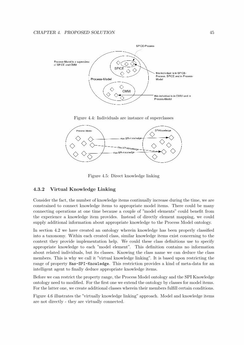
CHAPTER 4. PROPOSED SOLUTION 45
Figure 4.4: Individuals are instance of superclasses
Figure 4.5: Direct knowledge linking
4.3.2 Virtual Knowledge Linking
Consider the fact, the number of knowledge items continually increase during the time, we areconstrained to connect knowledge items to appropriate model items. There could be manyconnecting operations at one time because a couple of ”model elements” could benefit fromthe experience a knowledge item provides. Instead of directly element mapping, we couldsupply additional information about appropriate knowledge to the Process Model ontology.
In section 4.2 we have created an ontology wherein knowledge has been properly classifiedinto a taxonomy. Within each created class, similar knowledge items exist concerning to thecontext they provide implementation help. We could these class definitions use to specifyappropriate knowledge to each ”model element”. This definition contains no informationabout related individuals, but its classes. Knowing the class name we can deduce the classmembers. This is why we call it ”virtual knowledge linking”. It is based upon restricting therange of property Has-SPI-Knowledge. This restriction provides a kind of meta-data for anintelligent agent to finally deduce appropriate knowledge items.
Before we can restrict the property range, the Process Model ontology and the SPI Knowledgeontology need to modified. For the first one we extend the ontology by classes for model items.For the latter one, we create additional classes wherein their members fulfill certain conditions.
Figure 4.6 illustrates the ”virtually knowledge linking” approach. Model and knowledge itemsare not directly - they are virtually connected.
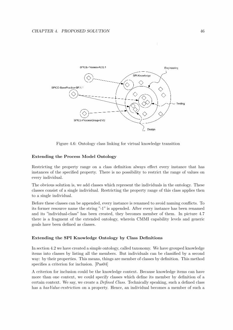
CHAPTER 4. PROPOSED SOLUTION 46
Figure 4.6: Ontology class linking for virtual knowledge transition
Extending the Process Model Ontology
Restricting the property range on a class definition always effect every instance that hasinstances of the specified property. There is no possibility to restrict the range of values onevery individual.
The obvious solution is, we add classes which represent the individuals in the ontology. Theseclasses consist of a single individual. Restricting the property range of this class applies thento a single individual.
Before these classes can be appended, every instance is renamed to avoid naming conflicts. Toits former resource name the string ”-1” is appended. After every instance has been renamedand its ”individual-class” has been created, they becomes member of them. In picture 4.7there is a fragment of the extended ontology, wherein CMMI capability levels and genericgoals have been defined as classes.
Extending the SPI Knowledge Ontology by Class Definitions
In section 4.2 we have created a simple ontology, called taxonomy. We have grouped knowledgeitems into classes by listing all the members. But individuals can be classified by a secondway: by their properties. This means, things are member of classes by definition. This methodspecifies a criterion for inclusion. [Pas04]
A criterion for inclusion could be the knowledge context. Because knowledge items can havemore than one context, we could specify classes which define its member by definition of acertain context. We say, we create a Defined Class. Technically speaking, such a defined classhas a hasValue-restriction on a property. Hence, an individual becomes a member of such a

CHAPTER 4. PROPOSED SOLUTION 47
Figure 4.7: Providing ”Instance-classes” to enable virtual knowledge mapping
class whenever at least one of its property values is equal to the hasValue resource.
Concerning SPI Knowledge we create classes which restrict on property Has-Knowledge-Context by a certain context value. They are then arranged as sub-classes of class SPI-Knowledge. Individuals which are member of class SPI-Knowledge and which have a contextof the specified value, are member of the defined class.
Suppose we wanted to describe a sub-class of class SPI-Knowledge called Software-Designwith a hasValue-Restriction on property Has-Knowledge-Context to value Software-Design-CONTEXT. The condition we have specified is read as, ”every knowledge item that has thespecified value on this property, is member of the defined class and also member of its super-classes”. In listing 4.1 a source-code fragment is showed for an owl:hasValue-Condition.
<owl:Class rdf:ID="Acquisition -Preparation">2 <rdfs:subClassOf >
<owl:Class rdf:about="#Acquisition"/>4 </rdfs:subClassOf >
<owl:equivalentClass >6 <owl:Restriction >
<owl:onProperty >8 <owl:ObjectProperty rdf:ID="Has -Knowledge -Context"/>
</owl:onProperty >10 <owl:hasValue >
<SPI -Knowledge -Context rdf:ID="Acquisition -Preparation -CONTEXT"/>
12 </owl:hasValue ></owl:Restriction >
14 </owl:equivalentClass >

CHAPTER 4. PROPOSED SOLUTION 48
</owl:Class >
Listing 4.1: Example of a defined class
Relevant, not explicit given facts, could be only by means of Logical Reasoning inferred.Logical reasoning goes back to the research field of description logics (DL).
Knowledge Range Restriction
Web Ontology Language allows a lot of options to create simple or more complex conditionsfor property restrictions. For example, we could restrict the range of a property to a singleclass or to a union or an intersection of classes to make highly customizable expressions.However, we limit the extent of expressions to relatively simple expressions which effect asingle class and a union or an intersection of separate classes:
∀ Has-SPI-Knowledge (KNOWLEDGE-RESTRICTION)∀ Has-SPI-Knowledge (KNOWLEDGE-RESTRICTION t KNOWLEDGE-RESTRICTION)∀ Has-SPI-Knowledge (KNOWLEDGE-RESTRICTION u KNOWLEDGE-RESTRICTION)
An example is given in listing 4.2 wherein related knowledge items of SPICE ManagementProcess come from a union of two separate knowledge classes.
1 <owl:Class rdf:ID="SPICE -Process -MAN.1"><rdfs:subClassOf >
3 <owl:Class rdf:about="#SPICE -Process"/></rdfs:subClassOf >
5 <rdfs:subClassOf ><owl:Restriction >
7 <owl:onProperty ><owl:ObjectProperty rdf:ID="Has -SPI -Knowledge"/>
9 </owl:onProperty ><owl:allValuesFrom >
11 <owl:Class ><owl:unionOf rdf:parseType="Collection">
13 <rdf:Description rdf:about="http://www.andre -frenzel.de/ont/spi -knowledge#Engineering -RESTRICTION"/>
<rdf:Description rdf:about="http://www.andre -frenzel.de/ont/spi -knowledge#Improvement -RESTRICTION"/>
15 </owl:unionOf ></owl:Class >
17 </owl:allValuesFrom ></owl:Restriction >
19 </rdfs:subClassOf ></owl:Class >
Listing 4.2: Example of an union restriction class
This example is an XML source-code snippet wherein OWL, RDFS and RDF statementsare serialized. In line 1 resource SPICE-Process-MAN.1 is denoted as ontology class. It isarranged as sub-class to SPICE-Process in line 2-4 and to an anonymous class that is defined

CHAPTER 4. PROPOSED SOLUTION 49
in line 5-19. A new class is defined by the anonymous class wherein any individual is memberof this class, if it satisfy the condition defined as restriction (line 6-18) on property Has-SPI-Knowledge (line 7-9). The condition is defined by an universal quantifier (line 10-17). Inline 12 to 15 applies a union operator for classes Management-RESTRICTION and Improvement-RESTRICTION that are defined in namespace http://www.andre-frenzel.de/ont/spi-knowledge#.
4.4 Meta-Data for the Purpose of Process Model Browsing
Process Models consist of a multiplicity of concepts and plenty of model elements. A properProcess Model browsing structure is therefore the most important matter for a supportingsoftware tool. To achieve a good browsing structure we need rules which define a feasible wayto browse through Process Models.
Web Ontology Language provides a feature that helps us to make statement about classes, e.g.to exclude classes or relationships from a tree navigation. The feature is called annotationto provide explanatory notes, like comments, which are allowed to classes, properties andindividuals. They need to be explicitly declared by property owl:AnnotationProperty. Suchannotation property could be processed as a kind of metadata statement by an intelligentagent that is, for example, in charge of creating the navigation structure.
In the following use of annotation is described for some cases.
Including/Excluding Resources for a Tree Browsing Structure Fortunately, theontology of Process Model exists of a hierarchical structure upon a tree navigation structurecould be built. However, any concept and relation should not be appear within the treestructure. Using annotation property AllowAsNode we become enable to state about classesthat they should appear within a tree navigation structure. Allowing or disallowing impliesa boolean datatype.
We could reuse this annotation property to state about object properties. Object propertiesrepresent relations from and to entities that could be also included/excluded from a treenavigation. It is up to the ontology maintainer if he decides to include a relationship ornot. For example, object property Has-SPICE-ProcessGroup should not be appear in a tree,however, the opposite site could.
Labeling Tree Model Items Classes and relationships are denoted by its resource name.However this resource name is just a unique identifier within the ontology vocabulary. Forpresentation purpose we need extra information, for instance, a well-defined name or a labelthat appears in navigation tree instead of the resource identifier. We could use the annotationproperty rdfs:label for this purpose that resists in RDF Schema namespace.
Avoiding Infinite Loops The Process Model structure is sometimes not hierarchical.There might be cross-references between classes. This could be cause infinite loops during thetime the tree data model is being built.

CHAPTER 4. PROPOSED SOLUTION 50
For example, class SPICE-ProcessAttribute and SPICE-Process exist in different dimen-sions, the first is in the capability dimension, the latter is in the process dimension. Bothclasses have relationships to each other. There could be cross-references in deeper classes oreven in the same class that cause trouble when a tree model is being constructed. There couldbe two possible solutions:
1. Both relations are excluded from the tree by using property AllowAsNode
2. The resource at the end of the relation becomes a leaf in the tree. If it is selected, it isswitched to the the ”original” item existing within the other dimension. Such relationscould be denoted by a annotation property called SwitchToItem.

Chapter 5
Implementation
This chapter introduces the thesis outcome in the form of a prototypical software tool thatimplements the elaborated ontology of a generic Process Model and it enables knowledgetransition by using ”virtually knowledge linking”.
In the following the programming and deployment environment will be shortly described,before a detailed description of the software architecture is given, which is driven by a Model-View-Controller paradigm.
Frameworks that notably contribute to the implementation will be briefly explained and theirimpact on the implementation will be shown. Wherever applicable open-source softwarebecomes first draw to commercial products.
This thesis finally has produced an outcome of software that has been termed to SPI Browser.This name denote the primary intension for being a software tool that supports SoftwareProcess Improvement.
5.1 Programming and Runtime Environment
Considerable the best programming language available for implementation purpose is some-times up to the individual preferences. The market is full of professional programming lan-guages. But for the purpose of ontology processing it is up to the 3rd party software whichApplication Programming Interfaces (API) is offered in which language.
Two favorite open-source ontology processing frameworks are presently on market. One of themost popular is JENA Ontology Framework. It has been taken under detailed considerationin section 5.3. Its enormously functional range is offered through a Java API.
For the second criterion, the programming language should be able to offer good practicesfor Web-Development. Web-Development means, making application available for the Web.SUN Microsystems is offering a key technology for enabling ”rapid development of web-basedapplications” naming to JavaServer Pages (JSP)1.
1JavaServer Pages Technology is available at http://java.sun.com/products/jsp/
51

CHAPTER 5. IMPLEMENTATION 52
JavaServer Pages
JavaServer Pages are part of Java 2 Enterprise Edition (J2EE) that is based on the Java 2Standard Edition (J2SE) which is primary for local desktop applications. J2EE is additionallyenhanced by server-side components for business applications.
JavaServer Pages is basically an extension to Java Servlets. Servlets are mainly designed tocreate dynamic Web pages. A JSP page is a text-based document that contains two types oftext: static template data, which can be expressed in any text-based format, such as HTMLand XML; and JSP elements, which construct dynamic content.
Apache Tomcat
Java Servlets life-cycle is managed by a Servlet Container. Servlet container that additionallysupport JSP technology are called Web-Container. Such an application is responsible forthe entire servlet life-cycle: creating, loading, initialization, destroying and handling clientrequests for servlets.
Apache Tomcat2 is the Web-Container that is used in the official reference implementationfor the Java Servlet and JavaServer Pages technologies. It has been developing within theJakarta sub-project of the Apache Software Foundation. Tomcat has been published underopen-source ever since and it has become the most popular Web container in the open-sourcescene. The current stable development tree is 5.0.x available for any operating system wherea Java Virtual Machine (JVM) greater version 1.4 is available.
The prototype of the SPI Browser is deployed under following address:http://www.andre-frenzel.de:8080/SPIBrowser.
Required Software Packages
For tracking the progressive of the prototypical implementation a non-production server hasbeen set-up. The operating system the server is running on is Linux under Debian 3.1 Sargedistribution. The Software packages are almost on the latest version. A list of packages isquoted in table 5.2.
5.2 Model-View-Controller Web-Architecture
One of the ever mentioned design goals of particular web application is to separate businesslogic, presentation logic and controller logic. This paradigm has become famous as Model-View-Controller-Architecture, shortly MVC-Architecture. The purpose of MVC is to provideflexibility of the software architecture and re-use of software components.
MVC is a design pattern for interactive applications that is organized into three separatemodules: the application model for data representation and business logic, the second for
2Apache Jakarta Tomcat is available at http://jakarta.apache.org/tomcat/

CHAPTER 5. IMPLEMENTATION 53
Software Package Version DescriptionApache Tomcat 5.0.28 Servlet and JSP ContainerJava Virtual Machine 1.4.2-06 Java Runtime EnvironmentStruts Framework 1.2.4 Web-Framework based on MVC-ArchitectureJena Framework 2.2 beta Framework for RDF, RDFS, OWL processingCommonControls 1.2.075 Control elements e.g. for trees
Table 5.2: Required software packages for the runtime environment
views responsible for user input and presentation layer and the third for controller to dispatchuser requests. [SUN02]
Figure 5.1: Web-tier controller
A Web application architecture that uses MVC to organize the Web application design isnamed to Web-tier architecture. The architecture’s center is formed by the Web-tier controllerdepicted in figure 5.1. It receives incoming HTTP request and invokes the requested businesslogic method. Based on the results of the operation and state of the application model, thecontroller then selects the next view to display. Finally the controller generates the selectedview and transmits it to the client for presentation.
5.2.1 Struts Web-Framework
One of the most popular and powerful open-source Web-Framework at the time is Struts3. Itis part of the Jakarta project hosted by Apache.
Struts Framework provides the application architecture based on Model 2 approach, a vari-ation of MVC design paradigm, where the request processing is performed in Java Servletsrather than in JSP pages (JSP Model 1). [Ses99]
The JSP Model 2 architecture, shown in figure 5.2, combines the use and advantages of JavaServlets and JSP. Servlets perform as the controller for process-intensive task while JSP isfor generating the presentation layer. [Ses99]
3Apache Struts is available at http://struts.apache.org/

CHAPTER 5. IMPLEMENTATION 54
Figure 5.2: Model2/MVC Architecture
Struts Model, View and Controller Components
The Struts information flow illustrated in picture 5.3 is very similar to plain Model 2 ap-plications. Any incoming request (1) is dispatched (2) through a single Servlet Controller.Depending on the user request the controller creates responsible Action classes. Action classesare built by the developer to perform the work of the application. Within action classes theapplication Model is changed either by updating (3) the internal state or by invoking Jav-aBeans to perform the actual business logic. Actions focuses rather on error handling andcontrol flow, but not on performing the business logic.
As result of the Business Logic operation the attained Java Bean is stored in the applicationrequest or session context. The control is then forwarded (4) by controller to the view. Thecorresponding JSP is now able to fetch the JavaBean from the application context, to createthe output page and to transmit (5) it to the client.
Figure 5.3: Struts flow
Central part of the Struts framework is the Struts deployment descriptor struts-config.xml.All configuration work for Struts-based applications is done here. The Struts configurationconsists of several parts that set-up Model components (FormBeans), Controller behavior(Actions), plugins as well as data sources and message resources.

CHAPTER 5. IMPLEMENTATION 55
5.2.2 Struts Configuration for the SPI Browser
Relevant Struts components can be best described on the SPI Browsers architecture itself.Additionally, it is given some further explanation about significant components.
Form Beans
FormBeans are derived from class ActionForm which can be considered both as Model and asController. Input of your application such as properties of input forms or request parametersin hypertext links are mapped to the properties of the corresponding FormBean. They arefinally forwarded by the controller to the scope of a responsible Action class.
• itemRequestForm - formBean that consists of attributes for current user resourcerequest
• treeForm - consists of the request parameters when invoking a tree operation
• searchForm - stores the parameters when user invokes the search operation
Global Exceptions
Within Global Exception configuration section exception handler are defined that treat oc-curring exceptions thrown by Action classes.
• java.lang.Exception - defines a global exception handler for the most general exceptionthat is not catched within an Action class
Global Forwards
Global Forwards are instances of Action Forwards which map logical names to specific re-sources. Target could be either JSPs or another logical name that is processed by an Action.Global means that the flow from any Action could be forwarded a Global Forward. Forexample to the home site or to a login site when the session has been timed out.
• Page.Start - Global Forward to the application start site. It is sometimes used whensession is timed out and the application flow needs to be forwarded to start.
Action Mappings
Within this section the URI is mapped to an appropriate Action class. It is a good designrule to never access JSPs directly from a URI but from Action classes. The reason is either tolet application logic and business logic processed by Action (MVC paradigm) and to globallyaccess resources by the unique URI without changing any reference if the JSP will have beenrenamed.
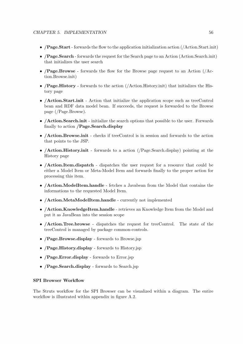
CHAPTER 5. IMPLEMENTATION 56
• /Page.Start - forwards the flow to the application initialization action (/Action.Start.init)
• /Page.Search - forwards the request for the Search page to an Action (Action.Search.init)that initializes the user search
• /Page.Browse - forwards the flow for the Browse page request to an Action (/Ac-tion.Browse.init)
• /Page.History - forwards to the action (/Action.History.init) that initializes the His-tory page
• /Action.Start.init - Action that initialize the application scope such as treeControlbean and RDF data model bean. If succeeds, the request is forwarded to the Browsepage (/Page.Browse).
• /Action.Search.init - initialize the search options that possible to the user. Forwardsfinally to action /Page.Search.display
• /Action.Browse.init - checks if treeControl is in session and forwards to the actionthat points to the JSP.
• /Action.History.init - forwards to a action (/Page.Search.display) pointing at theHistory page
• /Action.Item.dispatch - dispatches the user request for a resource that could beeither a Model Item or Meta-Model Item and forwards finally to the proper action forprocessing this item.
• /Action.ModelItem.handle - fetches a Javabean from the Model that contains theinformations to the requested Model Item.
• /Action.MetaModelItem.handle - currently not implemented
• /Action.KnowledgeItem.handle - retrieves an Knowledge Item from the Model andput it as JavaBean into the session scope
• /Action.Tree.browse - dispatches the request for treeControl. The state of thetreeControl is managed by package common-controls.
• /Page.Browse.display - forwards to Browse.jsp
• /Page.History.display - forwards to History.jsp
• /Page.Error.display - forwards to Error.jsp
• /Page.Search.display - forwards to Search.jsp
SPI Browser Workflow
The Struts workflow for the SPI Browser can be visualized within a diagram. The entireworkflow is illustrated within appendix in figure A.2.

CHAPTER 5. IMPLEMENTATION 57
5.3 Role of Jena Ontology Framework
Jena4 is a framework for building Semantic Web applications which business model is de-scribed in RDF or in ontologies by RDFS or OWL language. The creator of Jena SemanticWeb Framework has been Hewlett Packard’s Semantic Web Team. It has released Jena asopen-source for the community. Jena’s API architecture focuses on the RDF documents.RDF documents can be considered on three different levels of abstraction [DFvH03]:
• at the syntactic level ⇒ XML document
• at the structure level ⇒ RDF data model
• at the semantic level ⇒ graphs with predefined semantics (Ontologies)
Jena Framework enables to query about each of the abstraction levels. In figure 5.4 a possibledata flow within the Jena Ontology Framework is depicted.
Figure 5.4: Model data flow
Business Logic
The entire business logic is encapsulated within class RDFModelLoader. Its structure is illus-trated in figure 5.5. This class is responsible among other things for generating the ProcessModel tree navigation, querying the ontology model against a search request, achieving know-ledge transition, and so on.
The logic makes use of Jena’s ontology processing capabilities to traverse the ontology files atthe structural level. First of all, each ontology file is set up as instance of class OntModel, but
4Jena’s Web-site is at http://jena.sourceforge.net

CHAPTER 5. IMPLEMENTATION 58
Figure 5.5: SPI Browser class containing the business logic
with different OntModelSpec. While the ontology of SPI Knowledge is enabled for entailmentreasoning, the Process Model ontology is not. This is caused by the fact, knowledge items arenot asserted in sub-classes. In figure 5.6 the internal model structure of Jena is depicted
Figure 5.6: Jena’s internal model structure in the SPI Browser
Only by means of reasoning not stated knowledge items can be inferred. There exists three rea-
CHAPTER 5. IMPLEMENTATION 59
soner options: OWLMicro reasoner that comes with Jena, Pellet OWL Reasoner5 or RACER6.OWLMicro is the default reasoner.
5.4 Role of Common-Controls Framework
Common-Controls7 is a commercial presentation framework optimized for Struts that consistsof several control elements like lists, trees, tabfolders, menus and forms.
One of these controls, namely the treeControl -component, provides a tree navigation structure.It generates a tree which nodes can be exploded and closed. The programmer merely providesa tree data model through a simple interface. In the JSP-page treeControl configuration takesplace within a corresponding Java Taglib. The state of tree is managed by the treeControl-component itself.
Building the Tree Model
The tree data model is defined by implementing the common-controls tree interfaces: TreeN-odeDataModel and TreeGroupDataModel. However, it is sufficient to implement interfaceTreeGroupDataModel.
The data to build up the tree is retrieved from the ontology in terms of classes, propertiesand individuals. The tree data model is constructed starting from class Process-Model. sub-classes are mapped to folders in the tree to the point they include instances (⇒ Class Level).Those classes which haven not been annotated by property AllowAsNode are left out fromthe mapping and are not further processed. Classes which have an individual instance, theircorresponding tree node becomes a tree item (⇒ Item Level). This item is further consideredconcerning its properties which are explicit allowed to be displayed in the tree (⇒ PropertyLevel). In figure 5.7 a sample tree is depicted wherein the colored nodes indicate the differentprocessing levels.
5.5 Ontology Managing using Protege Ontology Editor
There is no user interface in the prototype yet that is for maintaining the data. Editing dataon the structural level (RDF level) is also not pretty. Fortunately there exist applications thatprovide an integrated view on the data and a smooth integration of ontology files. Such anapplication is Protege. Protege8 is an Java-based ontology and a knowledge base editor thatmakes it possible to modify ontologies. Is has been released as open-source and is thereforefree of use.
Protege has a quite open architecture. The functionality can be easily extended by appropriate5Pellet is an open-source Java based OWL DL reasoner available at http://www.mindswap.org/2003/
pellet/index.shtml6RACER is a Semantic Web inference engine for query answering over RDF documents and OWL ontologies.
It is available at http://www.cs.concordia.ca/~haarslev/racer/7Common Controls is available at http://www.common-controls.com8Protege Ontology Editor is available at http://protege.stanford.edu/

CHAPTER 5. IMPLEMENTATION 60
Figure 5.7: SPI Browser levels for tree navigation
plugins. Such a plugin is Protege-OWL which comes innately to the Protege environment.This plugin extends Protege in order to support the Web Ontology Language (OWL).
Within the scope of the proposed solution, Protege and OWL Plugin act the role of creatingand managing ontologies. Protege-OWL offers separate views for the most common compo-nents (classes, properties, individuals) in which they can be easily managed. In figure 5.8 isa screenshot of Protege showing the class view.
5.5.1 Ontology Infrastructure
Several options are available for providing a proper ontology infrastructure. Protege is enabledto read ontologies on three ways: locally file reading, remote file reading and database reading.This options are shortly below.
Local Access This is standard option and also current practice within the prototype envi-ronment. Ontology files are locally read, modified and stored. Files need then propagated to aserver by a remote file protocol using FTP or SSH. This approach allows ontology maintainerto put these files under version control and to locally test the integrity of data.

CHAPTER 5. IMPLEMENTATION 61
Figure 5.8: Protege ontology editor
Remote Access Another option is to update the ontology on a remote server. Protegeoffers an option to open a remote project and to update ontology files over network. Thisoption has not been proved if it is working properly.
Anyway this option has a couple of drawbacks:
• If more than one people are updating the ontology at the same time, racing conditionscould appear
• It is difficult to make an update of the remote ontology. It is even rather difficult toprovide version control for these files
Database Access Last but not least ontologies can be serialized into databases and ac-cessed by Protege and by Jena Framework using API connectors to the most popular open-source databases such MySQL or PostgreSQL.
Databases have a lot of advantages:
• Restrict or allow user to have access on data
• Allow concurrent access
• Backup of database is supported

CHAPTER 5. IMPLEMENTATION 62
• Optimized data storing and querying
5.5.2 Editing Scenarios
Ontology maintainer should be supported by changing, adding or dropping of informationthat are stored within an ontology. These tasks are further referred to as ontology editing.
In the following sections we give a briefly explanation on Protege-OWL, how ontology editingcould be managed concerning the following exposed use cases:
• Define virtual knowledge transition
• Define knowledge restricted classes
Hereby we refer to the terminology used in Protege-OWL that is unlike to the terminology ofOWL specification. More on Protege is given in [Hor04] that provides a good tutorial.
Define Virtual Knowledge Transition
As suggested in the solution part of this thesis, transition of knowledge is achieved by propertyrestrictions. In Protege-OWL we add restrictions either as NECESSARY CONDITION orNECESSARY & SUFFICIENT CONDITION a class. The first one can be read as, ”ifsomeone is a member of this class, then it is necessary to fulfill these conditions”. Necessary& sufficient condition means, ”the conditions are necessary for membership, they are alsosufficient to determine that any individual that satisfies them must be a member of theseclass. [Hor04]
In order to define knowledge transition we make a necessary condition on property Has-SPI-Knowledge. The condition is of type hasAllValuesFrom. This means, every instanceof this class has on property all values from the specified condition. This condition specifieseither a class, then it is an simple expression, or an operation on more classes, then it is acomplex expression. In picture 5.9 there is complex condition about a union of two knowledgerestricted classes.
Define Knowledge Restricted Classes
Knowledge restricted classes are defined concerning their context. Such classes define a cer-tain set of knowledge items that satisfy the given condition. Hereby inclusion depends on anecessary & sufficient condition. The restriction we create is a hasValue condition on propertyHas-Knowledge-Context. Only these knowledge items are member of a restricted class whichhave at least a value from the specified knowledge context. For an example see picture 5.10.
5.6 Technical Issues
Distinct Identifier for TreeControl Items The feature of switching branches when itemsare selected that exist within another dimension is considered to be necessary for the SPI

CHAPTER 5. IMPLEMENTATION 63
Figure 5.9: Defining knowledge transition in Protege
Browser.
When switching between branches it is necessary to know the key of the selected items.Unfortunately a tree item identifier is calculated during the tree is being built. A key is not aplain identifier, it is structured in parts that are calculated during the tree is processed fromthe top across the tree structure. Any element within the tree becomes an identifier part thatis separated by colon. This ensures making unique tree identifiers.
Following question arises: Why resource identifier cannot be used as a tree item identifier?If they can, selecting a certain tree item would lead to open more then one branch. Thisis because some items exist in several branches. However, tree item identifier cannot berecalculated from the ontology yet. By providing meta-data they could be determined.
Performance vs. Reasoning Performance of Semantic Web applications heavily dependson entailment reasoning. Reasoning demand a lot of processor and memory resources. Forcomplex ontologies the process of computing not asserted facts could take unreasonable time.The process of reasoning is thus enabled for the sub-model that is tied to SPI Knowledge.Allowing reasoning for the entire model could greatly enhance the speed for reasoning know-ledge items. However, some performance tests showed when reasoning is enabled for the entiremodel the speed was low. The time to calculate the union graph took sometime longer thana minute.
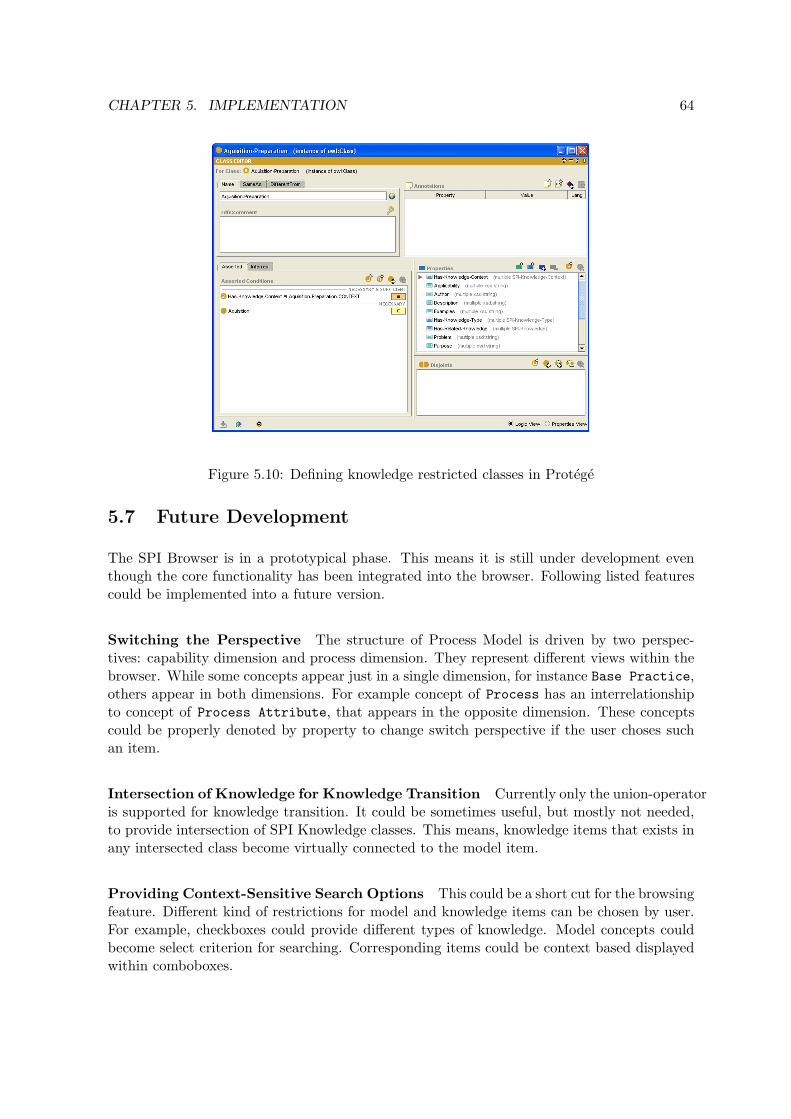
CHAPTER 5. IMPLEMENTATION 64
Figure 5.10: Defining knowledge restricted classes in Protege
5.7 Future Development
The SPI Browser is in a prototypical phase. This means it is still under development eventhough the core functionality has been integrated into the browser. Following listed featurescould be implemented into a future version.
Switching the Perspective The structure of Process Model is driven by two perspec-tives: capability dimension and process dimension. They represent different views within thebrowser. While some concepts appear just in a single dimension, for instance Base Practice,others appear in both dimensions. For example concept of Process has an interrelationshipto concept of Process Attribute, that appears in the opposite dimension. These conceptscould be properly denoted by property to change switch perspective if the user choses suchan item.
Intersection of Knowledge for Knowledge Transition Currently only the union-operatoris supported for knowledge transition. It could be sometimes useful, but mostly not needed,to provide intersection of SPI Knowledge classes. This means, knowledge items that exists inany intersected class become virtually connected to the model item.
Providing Context-Sensitive Search Options This could be a short cut for the browsingfeature. Different kind of restrictions for model and knowledge items can be chosen by user.For example, checkboxes could provide different types of knowledge. Model concepts couldbecome select criterion for searching. Corresponding items could be context based displayedwithin comboboxes.

CHAPTER 5. IMPLEMENTATION 65
Comments on Knowledge Items Comments could user encourage to provide their ex-perience to actual improvement cases. User might give response on knowledge items such ascritics, general comments, feasibility, realization, and so on. Comments could be consideredas a separate concept within the ontology of SPI Knowledge.
Separate Namespace for Browsing Annotation Properties The concept of annota-tion within OWL is primary used for presentation purposes e.g. labeling, building the treestructure, etc. (see 4.4).
Currently these annotation properties exist within the namespace for Process Models. How-ever, their purpose is for browsing. In a future version these properties could be arrangedwithin a separate namespace.

Chapter 6
Conclusion
This thesis has introduced an architecture that effectively supports Software Process Im-provement after Process Assessment. This architecture is based upon ontologies in whichseveral Process Models are integrated and knowledge for Software Process Improvement isrepresented. By languages intended for the Semantic Web these ontologies are implementedwithin a software tool related to Software Process Improvement. We will now summarize theresults and the contributions and we will give an outlook on the future research.
Summary
In this thesis we have pointed out that a generic Process Model is difficult to achieve andit comes along with loss of information. Instead, several Process Models can be representedwithin a single data model, then all the model related features are preserved. The data modelforms a hierarchical structure that can be transferred by mapping rules into an ontology. Theattained ontology works hereby as a meta-model that allows to make statements about thespecific concepts of Process Models. Upon this ontology a hierarchical browsing structurecan be constructed. Browsing related features can be specified by applying annotation uponontology classes, properties and individuals.
Knowledge for Software Process Improvement can be represented and classified within anontology, too. Since Web Ontology Language provides an import statement to include otherontologies, we use this feature to attain knowledge transition between elements from differentontologies. The way how knowledge transition takes place is up to two options. By means of”direct knowledge linking”, knowledge items are connected to Process Model items one to one.But knowledge is continually appended. Therefore, we advise to consider the option ”virtualknowledge linking”. This means, knowledge and model items are not physically mapped. It isbased upon restricting the range of related knowledge. Such restrictions are meta-data thatcould be extracted by a software agent to obtain related knowledge items.
We have presented a methodology how ontology facets can be maintained by an open-sourceontology editor, called Protege. It produces ontologies serialized into XML-RDF files whichcan be read and processed by Semantic Web frameworks.
The achievement of this thesis is a browser for Process Models, termed to SPI Browser.
66

CHAPTER 6. CONCLUSION 67
It is implemented as J2EE Web-Application that is driven by Apache Struts Model-View-Controller Architecture. Its business logic reads the serialized ontology files, and builds uponmeta-data a properly browsing structure. The intended use of the application is to browsethrough Process Models, in order to obtain the requirements and criteria for processes andto obtain knowledge for implementation.
Critique
Process Model browsing is based upon the structure of its data model. This structure isthe determining factor for a proper navigation through the models. If these models havea hierarchical structure, browsing could be well supported. However, if in Process Modelsa semantic exists it could not be represented within the data model. For example, CMMIcapability levels work as a kind of a selection mechanism for generic and specific practices,those are grouped into goals, for a certain process area. A possible navigation would be fromcapability level to process area to goal to practices. But practices are functional dependent oncapability levels and process area and not on goals, such a hierarchical structure is difficult,if at all, to attain.
Virtual knowledge linking is based upon a well designed knowledge ontology. Their classes arethen referenced to Process Model classes. Thus, changing the ontology class structure shouldnot be done afterwards. This means, any facets of knowledge must be considered duringontology designing in respect to the level it should provide implementation help. However,knowledge is multifarious and therefore good classification is hardly to achieve.
Outlook
The integration approach that several data model merge in a single data model can be used asa general basis for integrating arbitrary models. There could be simple models possible whichrepresent general goals in Software Process Improvement programs. For example, goals like”Better Productivity” or ”Better Team Collaboration”. These elements could be supportedby knowledge as well as by practices from Process Models.
If ”virtual knowledge linking”methodology is chosen, it is essential to construct an appropriateontology for knowledge that is based on a ”good” classification structure. Such classificationstructure must be granular enough to supply knowledge classes that can be mapped, forexample, to base practices and work products, if there is a need for it. In another thesis therecould be dealt with this question.
Further research is needed if continuous and staged CMMI should be integrated within asoftware tool. Because they address two different views on the same content, they could beimplemented within a single data model.

Appendix A
Diagrams
Figure A.1: Process Model ontology for use of direct knowledge linking
68

APPENDIX A. DIAGRAMS 69
Figure A.2: Struts workflow for the SPI Browser

Bibliography
[B+04] Sean Bechhofer et al. Owl web ontology language reference. Technical report,W3C World Wide Web Consortium, feb 2004. URL: http://www.w3.org/TR/2004/REC-owl-ref-20040210/.
[Bec04] Dave Beckett. Resource description framework syntax and grammar. Technicalreport, W3C World Wide Web Consortium, feb 2004. URL: http://www.w3.org/TR/2004/REC-rdf-syntax-grammar-20040210/.
[BG04] Dan Brickley and R.V. Guha. Rdf vocabulary description language 1.0: Rdfschema. Technical report, W3C World Wide Web Consortium, feb 2004. URL:http://www.w3.org/TR/2004/REC-rdf-schema-20040210/.
[BL+98] Berners-Lee et al. Uniform resource identifiers, generic syntax. Technical report,IETF The Internet Engineering Task Force, Aug 1998. URL: http://www.ietf.org/rfc/rfc2396.txt.
[BL00] Berners-Lee. Semantic web on xml. Powerpoint Presentation, Dez 2000. URL:http://www.w3.org/2000/Talks/1206-xml2k-tbl/slide10-0.html.
[BL03] Berners-Lee. Talks up semantic web. Internet News, Sep 2003. URL: http://www.internetnews.com/dev-news/article.php/3081191/.
[BL04] Berners-Lee. Das unvollendete. Technology Review, Nov 2004. URL: http://www.heise.de/tr/artikel/52516/0.
[Che76] Peter Pin-Shan Chen. The entity-relationship model - toward a unifies view ofdata. Technical report, Massachusetts Institute of Technology, Mar 1976. URL:http://bit.csc.lsu.edu/~chen/pdf/erd.pdf.
[DFvH03] J. Davies, D. Fensel, and F. von Harmelen. Towards THE SEMANTIC WEB.WILEY & SONS LTD, West Sussex, first edition, 2003.
[EDM98] Khaled El Eman, Jean-Normand Drouin, and Walcelio Melo. The Theory andPractice of Software Process Improvement and Capability. IEEE ComputerSociety Press, first edition, 1998.
[Ern03] Johannes Ernst. What are the differences between a vocabulary, a taxonomy,a thesaurus, an ontology, and a meta-model? metamodel.com, Jan 2003. URL:http://www.metamodel.com/article.php?story=20030115211223271.
70

BIBLIOGRAPHY 71
[Hor04] Matthew Horridge. A practical guide to building owl ontologies us-ing the protege-owl plugin and co-ode tools. Technical report, Univer-sity of Manchester, Aug 2004. URL: http://www.co-ode.org/resources/tutorials/ProtegeOWLTutorial.pdf.
[ISO01] ISO/IEC. Information Technology - Software Life Cycle Processes, Jul 2001.
[ISO04a] ISO/IEC. Information Technology - Process Assessment - Part 1: Conceptsand Vocabulary, May 2004.
[ISO04b] ISO/IEC. Information Technology - Process Assessment - Part 2: Performingan assessment, Jan 2004.
[ISO04c] ISO/IEC. Information Technology - Process Assessment - Part 4: Guidance onuse for Process Improvement and Process Capability Determination, Aug 2004.
[ISO04d] ISO/IEC. Information Technology - Process Assessment - Part 5: An examplarProcess Assessment Model, Jun 2004.
[LMV02] Marion Lepasaar, Timo Makinen, and Timo Varkoi. Structural comparison ofspice and continuous cmmi. Technical report, Tampere University of Technol-ogy, Pori, 2002.
[MM04] Frank Manola and Eric Miller. Resource description framwork primer. Technicalreport, W3C World Wide Web Consortium, feb 2004. URL: http://www.w3.org/TR/2004/REC-rdf-primer-20040210/.
[NM02] Natalya F. Noy and Deborah L. McGuinness. Ontology devlopment: Aguide to creating your first ontology. Technical report, Stanford Univer-sity, Jun 2002. URL: http://www.ksl.stanford.edu/people/dlm/papers/ontology-tutorial-noy-mcguinness.pdf.
[Pas04] Thomas B. Passin. Explorers Guide to the SEMANTIC WEB. Manning Pub-lication CO., Greenwich, first edition, 2004.
[RKd03] Pierre N. Robillard, Phillippe Kruchten, and Patrick d’Astous. Software Engi-neering Process with the UPEDU. Person Education, INC, Boston, first edition,2003.
[S+04] Michael K. Smith et al. Owl web ontology language guide. Technical report,W3C World Wide Web Consortium, feb 2004. URL: http://www.w3.org/TR/owl-guide/.
[SEI04] SEI. Cmmi models and modules, 2004. URL: http://www.sei.cmu.edu/cmmi/models/models.html.
[Ses99] Govind Seshadri. Understanding javaserver pages model 2 architecture.Java World, Dez 1999. URL: http://www.javaworld.com/javaworld/jw-12-1999/jw-12-ssj-jspmvc.html.
[SUN02] SUN Microsystems. Web-Tier Application Framework Design, 2002. URL:http://java.sun.com/blueprints/guidelines/designing_enterprise_applications_2e/web-tier/web-tier5.html.

BIBLIOGRAPHY 72
[WdHvdS97] K.-E Wiig, R. de Hoog, and R. van der Spek. Supporting km: A selectionof methods and techniques. In Expert Systems With Applications, volume 13,1997.
[WIK05a] Database, Apr 2005. URL: http://en.wikipedia.org/wiki/Database.
[WIK05b] Entity-relationship model, May 2005. URL: http://en.wikipedia.org/wiki/Entity_relationship.
[WIK05c] Knowledge, Apr 2005. URL: http://en.wikipedia.org/wiki/Knowledge.
[WIK05d] Ontology (computer science), Feb 2005. URL: http://en.wikipedia.org/wiki/Ontology_(computer_science).
[WIK05e] Process model, Apr 2005. URL: http://lexikon.freenet.de/Prozessmodell.
[Zie03] Cai Ziegler. Web ontology language (owl): Vokabulare furs web. IX, Dez 2003.

Statutory Declaration
I declare that I have developed and written the enclosed Diplomarbeit completely by myself,and have not used sources or means without declaration in the text. Any thoughts fromothers or literal quotations are clearly marked. The Diplomarbeit was not used in the sameor in a similar version to achieve an academic grading or is being published elsewhere.
....................................................... .......................................................Location, Date Andre Frenzel
73