ontrol product origin magnetic level gauges italy...float magnet then makes the roller display...
TRANSCRIPT
MAGNETIC level gauges
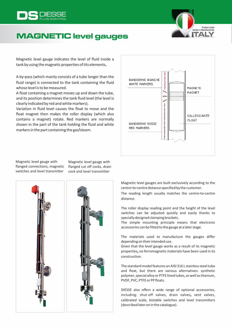
Magnetic level gauge indicates the level of fluid inside a tank by using the magnetic properties of tits elements.
A by-pass (which mainly consists of a tube longer than the fluid range) is connected to the tank containing the fluid whose level is to be measured.A float containing a magnet moves up and down the tube, and its position determines the tank fluid level (the level is clearly indicated by red and white markers).Variation in fluid level causes the float to move and the float magnet then makes the roller display (which also contains a magnet) rotate. Red markers are normally shown in the part of the tank holding the fluid and white markers in the part containing the gas/steam.
Magnetic level gauge with flanged cut off cocks, drain cock and level transmitter
Magnetic level gauge with flanged connections, magnetic switches and level transmitter
Magnetic level gauges are built exclusively according to the centre-to-centre distance specified by the customer.
The reading length usually matches the centre-to-centre distance.
The roller display reading point and the height of the level switches can be adjusted quickly and easily thanks to specially designed clamping brackets.The simple mounting principle means that electronic accessories can be fitted to the gauge at a later stage.
The materials used to manufacture the gauges differ depending on their intended use.Given that the level gauge works as a result of its magnetic properties, no ferromagnetic materials have been used in its construction.
The standard model features an AISI 316 L stainless steel tube and float, but there are various alternatives: synthetic polymer, special alloy or PTFE lined tubes, as well as titanium, PVDF, PVC, PTFE or PP floats.
DIESSE also offers a wide range of optional accessories, including: shut-off valves, drain valves, vent valves, calibrated scale, bistable switches and level transmitters (described later on in the catalogue).
DIESSEF L U I D C O N T R O LDS
Product originDesign & Manufacturing
ITALY

Magnetic level gauges are suitable for a wide range of applications and are a perfect alternative to glass level gauges if the latter cannot be used safely.
They are particularly recommended:
in cases where a particularly accurate fluid level reading is not necessary
in cases where the maximum pressure and temperature values exceed those listed in the technical specifications of the glasses
if remote readings have to be taken (e.g. if the level gauge is positioned above or a considerable distance away from the observer's position)
if continuous readings using a remote gauge situated some distance away from the system are necessary
if one or more signals (i.e. alarm signals) are required to indicate various tank liquid levels
if the centre-to-centre distance exceeds 3 metres
TO RECOMMEND THE MOST SUITABLE LEVEL GAUGE FOR A PARTICULAR PURPOSE,PLEASE PROVIDE THE FOLLOWING DATA WHEN ASKING FOR ADVICE OR A QUOTATION.
► essential data
►CENTRE-TO-CENTRE DISTANCE (distance between process connections)
► TYPE OF CONNECTIONS (flanged-threaded-weld-on) and related STANDARDS (UNI-ANSI-DIN…)
► TYPE OF FLUID
► SPECIFIC WEIGHT OF FLUID
► DESIGN AND MAXIMUM OPERATING PRESSURES
► DESIGN AND MAXIMUM OPERATING TEMPERATURES
•
•
• POSITION OF PROCESS CONNECTIONS
• POSITION OF THE VALVE HANDLING
•
•
•
•
• ANY ADDITIONAL ACCESSORIES
Specifications and design can be subject to change without notice

DIESSE magnetic level gauges are manufactured and certified in accordance with the strictest international standards.
Models are also available both ATEX 94/9/EC approved and with various Notified International Bodies approvals:
Aside from the type of fluid in the tank, the choice of level gauge mainly depends on the operating and design temperature/pressure values. These must always be clearly specified when asking for a quote or placing an order.
Magnetic level gauges differ in terms of their pressure ratings under operating conditions: low, medium and high.
DIESSEF L U I D C O N T R O LDS
MAGNETIC level gauges
Product originDesign & Manufacturing
ITALY

Process connections position:- standard: side/side
- additional options: side/bottom; top/side; top/bottom
Process connections type:- standard: with flanges, threaded tubes and butt weld tubes
- additional options: shut-off cocks (side/side) on request
Drain:- standard: threaded with plug
- additional options: threaded cock; other extras on request
Vent:- standard: threaded 1/2" with plug
- additional options: threaded cock; other extras on request
Gaskets:- standard: graphite/AISI 316
- additional options: PTFE/AISI 316, other extras on request
Accessories:Magnetic switch, Level transmitter, Control unit, Calibrated scale, Non-frosting extension, Minimum level arrow, Shut-off cocks, Drain cock, Vent cock, Cocks handles lock (see from page 2.13)
Certifications (on request):- ATEX
- Tests and inspection by Notified Bodies
- Others on request
1/2"
Materials / Specifications:
The different versions available are as follows:
Aluminium / Brass epoxy painted
Alluminium / PBT
Aluminium / Ceramic
With stainless steel cover / PBT
With stainless steel cover / Ceramic
Class
PN 16 - PN 25
PN 40
PN 63
PN 100
Execution
With steam tracing system
Liquid gas design
E-CTFE coated
PFA coated
E-TFE coated
PVC
Polipropylene
PVDF
For guided wave radar
Top mounted
Chamber
Stainless steel 316L
Stainless steel 316Ti
Stainless steel electro-polished
Stainless steel E-CTFE coated
Stainless steel PFA coated
Stainless steel E-TFE coated
TitaniumHastelloy CSuperaustenitic stainless steel(6Mo)
PVCPolipropylene
PVDF
Galleggiante
Stainless steel 316L
Stainless steel 316Ti
Titanium Grade 2
Hastelloy C
PVCPolipropylene
PVDF
Borosilicate glass
Stainless steel E-CTFE coated
Stainless steel PFA coated
Titanium PFA coated
Titanium E-CTFE coated
Housing / Rollers
PN 160
PN 250 - PN 400
accordance with company quality procedures and the industry regulations currently in effect.Certificates can be issued on request.
All DIESSE products are individually checked and tested in
Specifications and design can be subject to change without notice
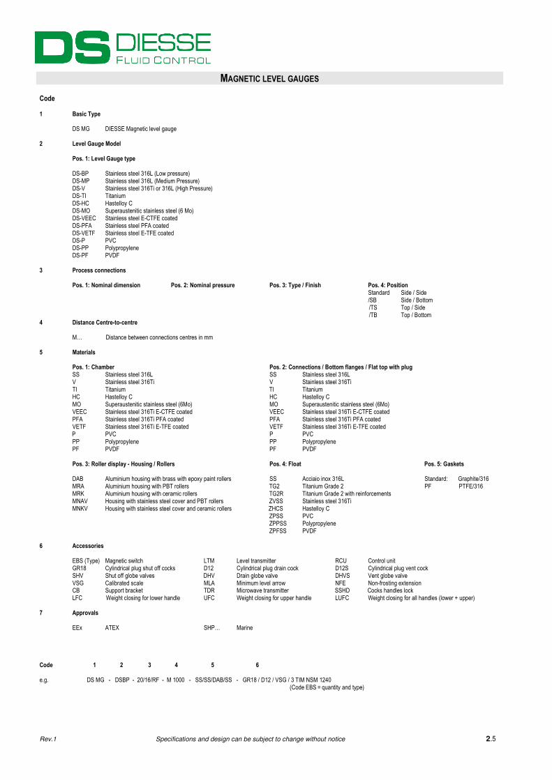
MAGNETIC LEVEL GAUGES Code 1 Basic Type DS MG DIESSE Magnetic level gauge 2 Level Gauge Model
Pos. 1: Level Gauge type
DS-BP Stainless steel 316L (Low pressure) DS-MP Stainless steel 316L (Medium Pressure) DS-V Stainless steel 316Ti or 316L (High Pressure) DS-TI Titanium DS-HC Hastelloy C DS-MO Superaustenitic stainless steel (6 Mo) DS-VEEC Stainless steel E-CTFE coated DS-PFA Stainless steel PFA coated DS-VETF Stainless steel E-TFE coated DS-P PVC DS-PP Polypropylene DS-PF PVDF
3 Process connections Pos. 1: Nominal dimension Pos. 2: Nominal pressure Pos. 3: Type / Finish Pos. 4: Position
Standard Side / Side /SB Side / Bottom /TS Top / Side /TB Top / Bottom 4 Distance Centre-to-centre
M… Distance between connections centres in mm
5 Materials
Pos. 1: Chamber Pos. 2: Connections / Bottom flanges / Flat top with plug SS Stainless steel 316L SS Stainless steel 316L V Stainless steel 316Ti V Stainless steel 316Ti TI Titanium TI Titanium HC Hastelloy C HC Hastelloy C MO Superaustenitic stainless steel (6Mo) MO Superaustenitic stainless steel (6Mo) VEEC Stainless steel 316Ti E-CTFE coated VEEC Stainless steel 316Ti E-CTFE coated PFA Stainless steel 316Ti PFA coated PFA Stainless steel 316Ti PFA coated VETF Stainless steel 316Ti E-TFE coated VETF Stainless steel 316Ti E-TFE coated P PVC P PVC PP Polypropylene PP Polypropylene PF PVDF PF PVDF
Pos. 3: Roller display - Housing / Rollers Pos. 4: Float Pos. 5: Gaskets
DAB Aluminium housing with brass with epoxy paint rollers SS Acciaio inox 316L Standard: Graphite/316 MRA Aluminium housing with PBT rollers TG2 Titanium Grade 2 PF PTFE/316
MRK Aluminium housing with ceramic rollers TG2R Titanium Grade 2 with reinforcements MNAV Housing with stainless steel cover and PBT rollers ZVSS Stainless steel 316Ti MNKV Housing with stainless steel cover and ceramic rollers ZHCS Hastelloy C ZPSS PVC ZPPSS Polypropylene ZPFSS PVDF
6 Accessories EBS (Type) Magnetic switch LTM Level transmitter RCU Control unit
GR18 Cylindrical plug shut off cocks D12 Cylindrical plug drain cock D12S Cylindrical plug vent cock SHV Shut off globe valves DHV Drain globe valve DHVS Vent globe valve VSG Calibrated scale MLA Minimum level arrow NFE Non-frosting extension CB Support bracket TDR Microwave transmitter SSHD Cocks handles lock LFC Weight closing for lower handle UFC Weight closing for upper handle LUFC Weight closing for all handles (lower + upper) 7 Approvals EEx ATEX SHP… Marine Code 1 2 3 4 5 6 e.g. DS MG - DSBP - 20/16/RF - M 1000 - SS/SS/DAB/SS - GR18 / D12 / VSG / 3 TIM NSM 1240 (Code EBS = quantity and type)
Rev.1 Specifications and design can be subject to change without notice 2.5
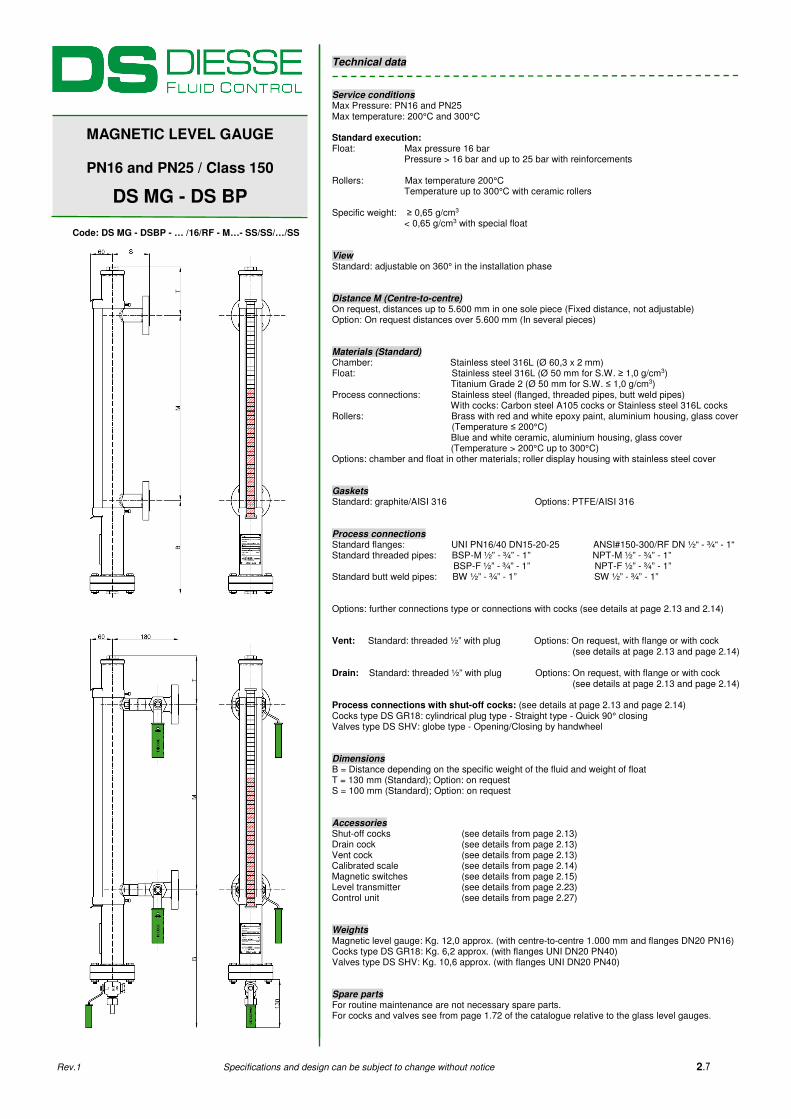
Technical data Service conditions Max Pressure: PN16 and PN25 Max temperature: 200°C and 300°C Standard execution:
Float: Max pressure 16 bar Pressure > 16 bar and up to 25 bar with reinforcements Rollers: Max temperature 200°C Temperature up to 300°C with ceramic rollers Specific weight: ≥ 0,65 g/cm3 < 0,65 g/cm3 with special float View Standard: adjustable on 360° in the installation phase Distance M (Centre-to-centre) On request, distances up to 5.600 mm in one sole piece (Fixed distance, not adjustable) Option: On request distances over 5.600 mm (In several pieces) Materials (Standard) Chamber: Stainless steel 316L (Ø 60,3 x 2 mm) Float: Stainless steel 316L (Ø 50 mm for S.W. ≥ 1,0 g/cm3) Titanium Grade 2 (Ø 50 mm for S.W. ≤ 1,0 g/cm3) Process connections: Stainless steel (flanged, threaded pipes, butt weld pipes) With cocks: Carbon steel A105 cocks or Stainless steel 316L cocks Rollers: Brass with red and white epoxy paint, aluminium housing, glass cover
(Temperature ≤ 200°C) Blue and white ceramic, aluminium housing, glass cover (Temperature > 200°C up to 300°C) Options: chamber and float in other materials; roller display housing with stainless steel cover Gaskets Standard: graphite/AISI 316 Options: PTFE/AISI 316 Process connections Standard flanges: UNI PN16/40 DN15-20-25 ANSI#150-300/RF DN ½“ - ¾“ - 1“ Standard threaded pipes: BSP-M ½” - ¾” - 1” NPT-M ½” - ¾” - 1” BSP-F ½” - ¾” - 1” NPT-F ½” - ¾” - 1” Standard butt weld pipes: BW ½” - ¾” - 1” SW ½” - ¾” - 1” Options: further connections type or connections with cocks (see details at page 2.13 and 2.14) Vent: Standard: threaded ½” with plug Options: On request, with flange or with cock (see details at page 2.13 and page 2.14) Drain: Standard: threaded ½” with plug Options: On request, with flange or with cock (see details at page 2.13 and page 2.14) Process connections with shut-off cocks: (see details at page 2.13 and page 2.14) Cocks type DS GR18: cylindrical plug type - Straight type - Quick 90° closing Valves type DS SHV: globe type - Opening/Closing by handwheel Dimensions B = Distance depending on the specific weight of the fluid and weight of float T = 130 mm (Standard); Option: on request S = 100 mm (Standard); Option: on request Accessories Shut-off cocks (see details from page 2.13) Drain cock (see details from page 2.13) Vent cock (see details from page 2.13) Calibrated scale (see details from page 2.14) Magnetic switches (see details from page 2.15) Level transmitter (see details from page 2.23) Control unit (see details from page 2.27) Weights Magnetic level gauge: Kg. 12,0 approx. (with centre-to-centre 1.000 mm and flanges DN20 PN16) Cocks type DS GR18: Kg. 6,2 approx. (with flanges UNI DN20 PN40) Valves type DS SHV: Kg. 10,6 approx. (with flanges UNI DN20 PN40) Spare parts For routine maintenance are not necessary spare parts. For cocks and valves see from page 1.72 of the catalogue relative to the glass level gauges.
MAGNETIC LEVEL GAUGE
PN16 and PN25 / Class 150
DS MG - DS BP
Code: DS MG - DSBP - … /16/RF - M…- SS/SS/…/SS
Rev.1 Specifications and design can be subject to change without notice 2.7

Technical data Service conditions Max Pressure: PN16 and PN25 Max temperature: 200°C and 300°C Standard execution:
Float: Max pressure 16 bar Pressure > 16 bar and up to 25 bar with reinforcements Rollers: Max temperature 200°C Temperature up to 300°C with ceramic rollers Specific weight: ≥ 0,65 g/cm3 < 0,65 g/cm3 with special float View Standard: adjustable on 360° in the installation phase Distance M (Centre-to-centre) On request, distances up to 5.600 mm in one sole piece (Fixed distance, not adjustable) Option: On request distances over 5.600 mm (In several pieces) Materials (Standard) Chamber: Stainless steel 316L (Ø 60,3 x 2 mm) Float: Stainless steel 316L (Ø 50 mm for S.W. ≥ 1,0 g/cm3) Titanium Grade 2 (Ø 50 mm for S.W. ≤ 1,0 g/cm3) Process connections: Stainless steel (flanged, threaded pipes, butt weld pipes) With cocks: Carbon steel A105 cocks or Stainless steel 316L cocks Rollers: Brass with red and white epoxy paint, aluminium housing, glass cover
(Temperature ≤ 200°C) Blue and white ceramic, aluminium housing, glass cover (Temperature > 200°C up to 300°C) Options: chamber and float in other materials; roller display housing with stainless steel cover Gaskets Standard: graphite/AISI 316 Options: PTFE/AISI 316 Process connections Standard flanges: UNI PN16/40 DN15-20-25 ANSI#150-300/RF DN ½“ - ¾“ - 1“ Standard threaded pipes: BSP-M ½” - ¾” - 1” NPT-M ½” - ¾” - 1” BSP-F ½” - ¾” - 1” NPT-F ½” - ¾” - 1” Standard butt weld pipes: BW ½” - ¾” - 1” SW ½” - ¾” - 1” Options: further connections type or connections with cocks (see details at page 2.13 and 2.14) Vent: Standard: threaded ½” with plug Options: On request, with flange or with cock (see details at page 2.13 and page 2.14) Drain: Standard: threaded ½” with plug Options: On request, with flange or with cock (see details at page 2.13 and page 2.14) Process connections with shut-off cocks: (see details at page 2.13 and page 2.14) Cocks type DS GR18: cylindrical plug type - Straight type - Quick 90° closing Valves type DS SHV: globe type - Opening/Closing by handwheel Dimensions B = Distance depending on the specific weight of the fluid and weight of float T = 130 mm (Standard); Option: on request S = 100 mm (Standard); Option: on request Accessories Shut-off cocks (see details from page 2.13) Drain cock (see details from page 2.13) Vent cock (see details from page 2.13) Calibrated scale (see details from page 2.14) Magnetic switches (see details from page 2.15) Level transmitter (see details from page 2.23) Control unit (see details from page 2.27) Weights Magnetic level gauge: Kg. 10,0 approx. (with centre-to-centre 1.000 mm and threads 1/2" BSP-M) Cocks type DS GR18: Kg. 3,8 approx. (with threads 1/2" BSP-M) Valves type DS SHV: Kg. 8,8 approx. (with threads 1/2" BSP-M) Spare parts For routine maintenance are not necessary spare parts. For cocks and valves see from page 1.72 of the catalogue relative to the glass level gauges.
MAGNETIC LEVEL GAUGE
PN16 and PN25 / Class 150
DS MG - DS BP
Code: DS MG - DSBP - 1/2” GAS-M - M…- SS/SS/…/SS
Rev.1 Specifications and design can be subject to change without notice 2.8

Technical data Service conditions Max Pressure: PN40; Class 300 (49,6 bar @ 38°C) Max temperature: 200°C and 300°C Standard execution:
Float: Max pressure 40 bar; Class 300 (49,6 bar @ 38°C) Rollers: Max temperature 200°C Temperature up to 300°C with ceramic rollers Specific weight: ≥ 0,65 g/cm3 < 0,65 g/cm3 with special float View Standard: adjustable on 360° in the installation phase Distance M (Centre-to-centre) On request, distances up to 5.600 mm in one sole piece (Fixed distance, not adjustable) Option: On request distances over 5.600 mm (In several pieces) Materials (Standard) Chamber: Stainless steel 316L (Ø 60,3 x 2,77 mm) Float: Stainless steel 316L (Ø 50 mm for S.W. ≥ 1,0 g/cm3) Titanium Grade 2 (Ø 50 mm for S.W. ≤ 1,0 g/cm3) Process connections: Stainless steel (flanged, threaded pipes, butt weld pipes) With cocks: Carbon steel A105 cocks or Stainless steel 316L cocks Rollers: Brass with red and white epoxy paint, aluminium housing, glass cover
(Temperature ≤ 200°C) Blue and white ceramic, aluminium housing, glass cover (Temperature > 200°C up to 300°C) Options: chamber and float in other materials; roller display housing with stainless steel cover Gaskets Standard: graphite/AISI 316 Options: PTFE/AISI 316 Process connections Standard flanges: UNI PN40 DN15-20-25 ANSI#300-600/RF DN ½“ - ¾“ - 1“ Standard threaded pipes: BSP-M ½” - ¾” - 1” NPT-M ½” - ¾” - 1” BSP-F ½” - ¾” - 1” NPT-F ½” - ¾” - 1” Standard butt weld pipes: BW ½” - ¾” - 1” SW ½” - ¾” - 1” Options: further connections type or connections with cocks (see details at page 2.13 and 2.14) Vent: Standard: threaded ½” with plug Options: On request, with flange or with cock (see details at page 2.13 and page 2.14) Drain: Standard: threaded ½” with plug Options: On request, with flange or with cock (see details at page 2.13 and page 2.14) Process connections with shut-off cocks: (see details at page 2.13 and page 2.14) Cocks type DS GR18: cylindrical plug type - Straight type - Quick 90° closing Valves type DS SHV: globe type - Opening/Closing by handwheel Dimensions B = Distance depending on the specific weight of the fluid and weight of float T = 130 mm (Standard); Option: on request S = 100 mm (Standard); Option: on request Accessories Shut-off cocks (see details from page 2.13) Drain cock (see details from page 2.13) Vent cock (see details from page 2.13) Calibrated scale (see details from page 2.14) Magnetic switches (see details from page 2.15) Level transmitter (see details from page 2.23) Control unit (see details from page 2.27) Weights Magnetic level gauge: Kg. 12,0 approx. (with centre-to-centre 1.000 mm and flanges DN20 PN40) Cocks type DS GR18: Kg. 6,2 approx. (with flanges UNI DN20 PN40) Valves type DS SHV: Kg. 10,6 approx. (with flanges UNI DN20 PN40) Spare parts For routine maintenance are not necessary spare parts. For cocks and valves see from page 1.72 of the catalogue relative to the glass level gauges.
MAGNETIC LEVEL GAUGE
PN40 / Class 300
DS MG - DS MP
Code: DS MG - DSMP - … /40/RF - M…- SS/SS/…/SS
Rev.1 Specifications and design can be subject to change without notice 2.9

Technical data Service conditions Max Pressure: PN40; Class 300 (49,6 bar @ 38°C) Max temperature: 200°C and 300°C Standard execution:
Float: Max pressure 40 bar; Class 300 (49,6 bar @ 38°C) Rollers: Max temperature 200°C Temperature up to 300°C with ceramic rollers Specific weight: ≥ 0,65 g/cm3 < 0,65 g/cm3 with special float View Standard: adjustable on 360° in the installation phase Distance M (Centre-to-centre) On request, distances up to 5.600 mm in one sole piece (Fixed distance, not adjustable) Option: On request distances over 5.600 mm (In several pieces) Materials (Standard) Chamber: Stainless steel 316L (Ø 60,3 x 2,77 mm) Float: Stainless steel 316L (Ø 50 mm for S.W. ≥ 1,0 g/cm3) Titanium Grade 2 (Ø 50 mm for S.W. ≤ 1,0 g/cm3) Process connections: Stainless steel (flanged, threaded pipes, butt weld pipes) With cocks: Carbon steel A105 cocks or Stainless steel 316L cocks Rollers: Brass with red and white epoxy paint, aluminium housing, glass cover
(Temperature ≤ 200°C) Blue and white ceramic, aluminium housing, glass cover (Temperature > 200°C up to 300°C) Options: chamber and float in other materials; roller display housing with stainless steel cover Gaskets Standard: graphite/AISI 316 Options: PTFE/AISI 316 Process connections Standard flanges: UNI PN40 DN15-20-25 ANSI#300-600/RF DN ½“ - ¾“ - 1“ Standard threaded pipes: BSP-M ½” - ¾” - 1” NPT-M ½” - ¾” - 1” BSP-F ½” - ¾” - 1” NPT-F ½” - ¾” - 1” Standard butt weld pipes: BW ½” - ¾” - 1” SW ½” - ¾” - 1” Options: further connections type or connections with cocks (see details at page 2.13 and 2.14) Vent: Standard: threaded ½” with plug Options: On request, with flange or with cock (see details at page 2.13 and page 2.14) Drain: Standard: threaded ½” with plug Options: On request, with flange or with cock (see details at page 2.13 and page 2.14) Process connections with shut-off cocks: (see details at page 2.13 and page 2.14) Cocks type DS GR18: cylindrical plug type - Straight type - Quick 90° closing Valves type DS SHV: globe type - Opening/Closing by handwheel Dimensions B = Distance depending on the specific weight of the fluid and weight of float T = 130 mm (Standard); Option: on request S = 100 mm (Standard); Option: on request Accessories Shut-off cocks (see details from page 2.13) Drain cock (see details from page 2.13) Vent cock (see details from page 2.13) Calibrated scale (see details from page 2.14) Magnetic switches (see details from page 2.15) Level transmitter (see details from page 2.23) Control unit (see details from page 2.27) Weights Magnetic level gauge: Kg. 10,0 approx. (with centre-to-centre 1.000 mm and threads 1/2" BSP-M) Cocks type DS GR18: Kg. 3,8 approx. (with threads 1/2" BSP-M) Valves type DS SHV: Kg. 8,8 approx. (with threads 1/2" BSP-M) Spare parts For routine maintenance are not necessary spare parts. For cocks and valves see from page 1.72 of the catalogue relative to the glass level gauges.
MAGNETIC LEVEL GAUGE
PN40 / Class 300
DS MG - DS MP
Code: DS MG - DSBP - 1/2” GAS-M - M…- SS/SS/…/SS
Rev.1 Specifications and design can be subject to change without notice 2.10

MAGNETIC LEVEL GAUGES
PN63 Material: Stainless steel 316Ti or 316L Centre-to-centre distance: min. 150 to max. 5.600 mm (other dimensions on request) Pressure: -1…63 bar Temperature: max 200°C (with PBT rollers) max 300°C (with ceramic rollers) (other on request) Specific weight: ≥ 480 kg/m3
PN100 Material: Stainless steel 316Ti or 316L Centre-to-centre distance: min. 150 to max. 5.600 mm (other dimensions on request) Pressure: -1…100 bar Temperature: max 200°C (with PBT rollers) max 300°C (with ceramic rollers) (other on request) Specific weight: ≥ 390 kg/m3
PN160 Material: Stainless steel 316Ti or 316L Centre-to-centre distance: min. 150 to max. 5.600 mm (other dimensions on request) Pressure: -1…160 bar Temperature: max 200°C (with PBT rollers) max 300°C (with ceramic rollers) (other on request) Specific weight: ≥ 480 kg/m3
PN250 - PN400 Material: Stainless steel 316Ti or 316L Centre-to-centre distance: min. 150 to max. 5.600 mm (other dimensions on request) Pressure: -1…250 / 400 bar Temperature: max 200°C (with PBT rollers) max 300°C (with ceramic rollers) (other on request) Specific weight: ≥ 690 kg/m3
Liquid gas design Material: Stainless steel 316Ti or 316L Centre-to-centre distance: min. 150 to max. 5.600 mm (other dimensions on request) Pressure: -1…40 bar Temperature: max 200°C (with PBT rollers) max 300°C (with ceramic rollers) (other on request) Specific weight: ≥ 460 kg/m3
With steam tracing system Material: Stainless steel 316Ti or 316L Centre-to-centre distance: min. 150 to max. 5.600 mm (other dimensions on request) Pressure: -1…40 bar Temperature: max 200°C (with PBT rollers) max 300°C (with ceramic rollers) (other on request) Specific weight: ≥ 460 kg/m3
Rev.1 Specifications and design can be subject to change without notice 2.11
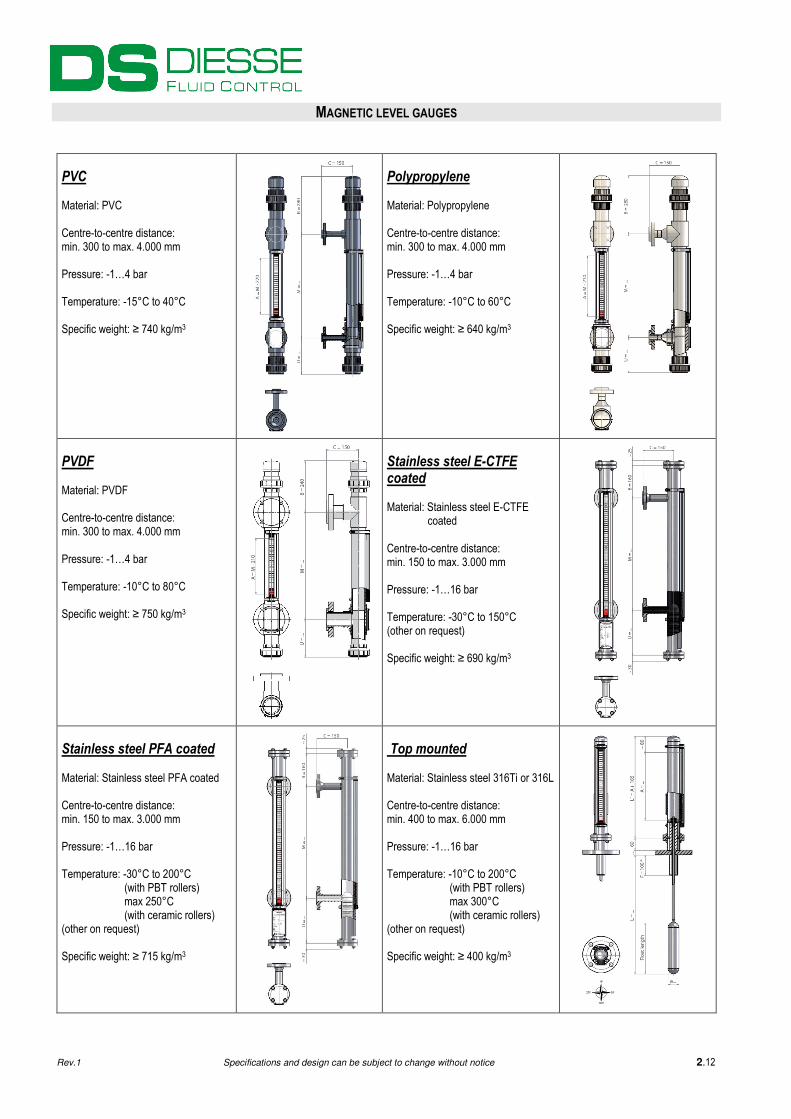
MAGNETIC LEVEL GAUGES
PVC Material: PVC Centre-to-centre distance: min. 300 to max. 4.000 mm Pressure: -1…4 bar Temperature: -15°C to 40°C Specific weight: ≥ 740 kg/m3
Polypropylene Material: Polypropylene Centre-to-centre distance: min. 300 to max. 4.000 mm Pressure: -1…4 bar Temperature: -10°C to 60°C Specific weight: ≥ 640 kg/m3
PVDF Material: PVDF Centre-to-centre distance: min. 300 to max. 4.000 mm Pressure: -1…4 bar Temperature: -10°C to 80°C Specific weight: ≥ 750 kg/m3
Stainless steel E-CTFE coated Material: Stainless steel E-CTFE
coated Centre-to-centre distance: min. 150 to max. 3.000 mm Pressure: -1…16 bar Temperature: -30°C to 150°C (other on request) Specific weight: ≥ 690 kg/m3
Stainless steel PFA coated Material: Stainless steel PFA coated Centre-to-centre distance: min. 150 to max. 3.000 mm Pressure: -1…16 bar Temperature: -30°C to 200°C (with PBT rollers) max 250°C (with ceramic rollers) (other on request) Specific weight: ≥ 715 kg/m3
Top mounted Material: Stainless steel 316Ti or 316L Centre-to-centre distance: min. 400 to max. 6.000 mm Pressure: -1…16 bar Temperature: -10°C to 200°C (with PBT rollers) max 300°C (with ceramic rollers) (other on request) Specific weight: ≥ 400 kg/m3
Rev.1 Specifications and design can be subject to change without notice 2.12