ontrolinc quick startup guide - emerson electric
TRANSCRIPT

Quick Startup GuideQSG-01-10-93-0014-EN Rev. 1
September 2020
Controlinc Quick Startup Guide

Quick Startup GuideQSG-01-10-93-0014-EN Rev. 1
NotesSeptember 2020
This page intentionally left blank
i
Quick Startup GuideQSG-01-10-93-0014-EN Rev. 1
Table of ContentsSeptember 2020
Table of Contents
Table of Contents
Section 1: Quick Start Guide1.1 Setup Instructions ................................................................................................91.2 Entering Setup Mode ...........................................................................................91.3 Changing Setup Parameters .................................................................................91.4 Exiting Setup Mode ..............................................................................................91.5 Direct Command Mode ......................................................................................101.6 Valve Control Mode ...........................................................................................101.7 Valve Travel Limits ..............................................................................................111.8 ESD Function ......................................................................................................111.9 ESD/Monitor Relay Function ...............................................................................121.10 ESD Trigger Sources ...........................................................................................121.11 ESD Delay Time ..................................................................................................131.12 Position Control Bandwidth ................................................................................141.13 Speed Control Bandwidth ..................................................................................141.14 Motor Starter Type .............................................................................................151.15 Analog Output Control .......................................................................................151.16 Modulation Delay Time ......................................................................................151.17 Network Response Delay Time ...........................................................................161.18 Torque Retry (Log-Jam) Control ..........................................................................161.19 Network Baud Rate ............................................................................................171.20 Network Parity ...................................................................................................181.21 Calibrate Analog I/O ...........................................................................................181.22 Calibrate Analog Inputs ......................................................................................191.23 Calibrate Analog Output ....................................................................................191.24 Load Factory Default Calibrate Values ................................................................201.25 User Relay #1 Application ...................................................................................201.26 User Relay #2 Application ...................................................................................211.27 LSA Position Setpoint .........................................................................................221.28 LSB Position Setpoint .........................................................................................221.29 Anti-water Hammer ...........................................................................................231.30 Opening Duty Cycle ON Timer ............................................................................231.31 Opening Duty Cycle OFF Timer ...........................................................................241.32 Closing Duty Cycle ON Timer ..............................................................................241.33 Closing Duty Cycle OFF Timer .............................................................................251.34 Write Protect .....................................................................................................261.35 Setpoint Tracking ...............................................................................................26

ii
Quick Startup GuideQSG-01-10-93-0014-EN Rev. 1
Table of ContentsSeptember 2020
Table of Contents
Section 2: Modbus Memory Map Reference2.1 Modbus Function Codes .....................................................................................272.2 Input Register Map .............................................................................................272.3 Input Register 03 (DCM320B only) .....................................................................282.4 Discrete Input Map .............................................................................................282.5 Coil Map .............................................................................................................292.6 Holding Register Map .........................................................................................30
Section 3: Network Installation GuideNetwork Installation Guide ..........................................................................................31
Section 4: System Startup GuideSystem Startup Guide ..................................................................................................33
Section 5: Optional Phase MonitorOptional Phase Monitor ...............................................................................................35
Section 6: Alarm Definitions and Troubleshooting GuideAlarm Definitions and Troubleshooting Guide ..............................................................37
Section 7: Diagnostic Features of 320B Controlinc M2CP7.1 High Water Mark Torque Data (Max Torque Profile) ............................................387.2 Full Stroke Test (FST) ..........................................................................................397.3 Partial Stroke Test (PST) .....................................................................................43

Preface
DCM320B is an upgrade of DCM320A. It is a fit, form, and function replacement for the DCM320A. The DCM320B may be used as a direct replacement of the DCM320A in existing installations. The primary difference is the DIP switch configuration method. The DCM320B provides more range and resolution of most configuration parameters. This handy reference is a guide to help you get your system up and running quickly. Refer to the wiring diagram supplied with the actuator for detailed wiring information. The first section of this guide will help you get your Controlinc actuators hooked-up and set-up correctly. If you need to change configuration of the unit, we recommend using our Windows based DCMLink rather than setting configuration DIP switches shown in this guide. Setting network station address DIP switches is required. The second section of this manual is the Modbus memory map reference to help configure your host database. If you are using the Controlinc Network Master, then refer to the manual supplied with that unit for memory maps. Section three of this manual is a brief system startup guide to help you do things in the proper order to achieve a successful system startup. This last section also covers optional phase monitor module. This document covers Revision F and later revision boards.
!WARNINGFailure to follow instructions for proper electrical wiring, storage, setup, and maintenance may cause serious injury, damage equipment, or void the warranty. Refer to Manual E796 for instructions on storage, electrical hook-up, and maintenance.

Quick Startup GuideQSG-01-10-93-0014-EN Rev. 1
NotesSeptember 2020
This page intentionally left blank

Quick Startup GuideQSG-01-10-93-0014-EN Rev. 1
September 2020
1
Section 1: Quick Start Guide
Quick Start Guide
Section 1: Quick Start GuideStep 1: Identify network topology
Identify network topology from Figures 2 and 3, and note the ports being used (Ports A,B,C,D). Refer to page 23 for guidance on network planning and installation.
Step 2: Set network jumpers and switches
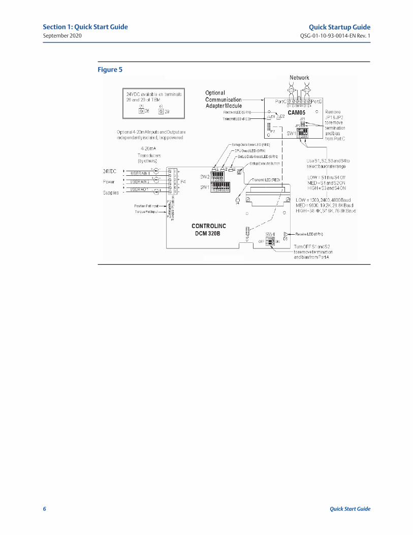
If network topology is parallel bus, then remove network termination and bias by turning OFF S1 and S2 of SW4 on the DCM 320B card. Remove jumpers JP1 and JP2 on the CAM05, if installed. Terminations must be left in the most distant unit on the network. If E>Net is selected, all ports must be terminated. Baudrate range selection is not required on DCM 320B but is required on CAM05. Refer to Figure 5 for jumper and DIP switch locations.
Step 3: Connect network wiring (Refer to page 23 for guidance)
Wire network ports selected in Step 1. Refer to Figure 4 when wiring Ports A and B on TBM 320A module. Refer to Figure 5 when wiring Ports C and D on the CAM05 module.
Step 4: Connect auxiliary I/O wiring
Refer to Figure 4 when connecting discrete auxiliary I/O wiring. Note that some functions must be jumpered between screw terminals if not wired to external contacts. Analog I/O wiring is connected to the DCM 320B module as shown in Figure 5.
Step 5: Set network station address
Each node (valve actuator) on the network must have a unique station address. Locate DIP switch SW1 on the DCM 320B card shown in Figure 5. Locate the desired station address on pages 7 and 8. Set the DIP switches of SW1 to the corresponding pattern shown beside the selected address. Press execute button to store address.
NOTE:
We highly recommend using the windows based DCMLink to configure the actuators. DCMLink is available at www.emerson.com or your local Actuation Technologies distributor. If using DCMLink, you may skip step 6 below.

Quick Startup GuideQSG-01-10-93-0014-EN Rev. 1
September 2020
2
Section 1: Quick Start Guide
Quick Start Guide
Figure 1 DCMLink Homescreen
Step 6: Select configuration parameters
The actuator may be configured using the 5 DIP switches of SW2 and 8 DIP switches of SW1. This is a back-up means of configuring the unit if DCMLink is not available. The actuator is normally shipped with factory default settings. These settings may be changed by the following procedure. Locate DIP switches SW1, SW2, and Setup Execute Button on the DCM 320B module shown in Figure 5. Place the Selector Switch in the "OFF" position. Select the feature or configuration parameter from the configuration tables in this manual. Set the DIP switches per the corresponding switch pattern and then press the execute button. If the configuration parameter is valid, the green (setup data good) LED will flash. If error data is entered, the red (setup data error) LED will light until the error is corrected. Repeat this procedure for each parameter to be revised. Return all 5 DIP switches of SW2 to the OFF position and return the 8 DIP switches of SW1 to the network station address when configuration is complete. With all SW2 switches OFF and the address switches set, press the execute button to store the network address to nonvolatile configuration memory.

Quick Startup GuideQSG-01-10-93-0014-EN Rev. 1
September 2020
3
Section 1: Quick Start Guide
Quick Start Guide
Single Multidrop Bus
Limits:32 units 4,000 ft total
Turn OFF S1 abd S2 of SW4 on 320B card
(except last actuator)
Limits:32 units 4,000 ft total
Requires CAM05 module
Limits:254 units 5,000 ft between units or 200 miles total
Limits:254 units 5,000 ft between units or 200 miles total
Limits:254 units 5,000 ft between units or 200 miles total
Requires CAM05 module
Limits:254 units 5,000 ft between units or 200 miles total
Requires CAM05 module
Turn OFF S1 and S2 of SW4 on DCM320B and remove JP1 and JP2 on CAM05 card
Limits based on EIA standard for RS485 bus networks
EIM Network Master required for ring network topology
E>Net requires network terminations and bias to be asserted at all ports of all series connected E>Net actuators. Networks may be a combination of parallel bus and series E>Net connections. Limit number of parallel connected units to 15 between series connected E>Net units.
Single E>Net
E>Net Ring
Redundant E>Net Ring
Redundant E>Net
Redundant Multidrop Bus
Figure 2 Controlinc Model 320B RS485 Network Topology Options

Quick Startup GuideQSG-01-10-93-0014-EN Rev. 1
September 2020
4
Section 1: Quick Start Guide
Quick Start Guide
ShieldBus Network
Shield
ShieldShieldE>Net
Jumpers common shield through the network
Figure 3

Quick Startup GuideQSG-01-10-93-0014-EN Rev. 1
September 2020
5
Section 1: Quick Start Guide
Quick Start Guide
Figure 4 TBM 320A Hook-up Diagram
NOTE:
TBM320A is used with both DCM320A and DCM320B.
Quick Startup GuideQSG-01-10-93-0014-EN Rev. 1
September 2020
6
Section 1: Quick Start Guide
Quick Start Guide
Figure 5
Quick Startup GuideQSG-01-10-93-0014-EN Rev. 1
September 2020
7
Section 1: Quick Start Guide
Quick Start Guide
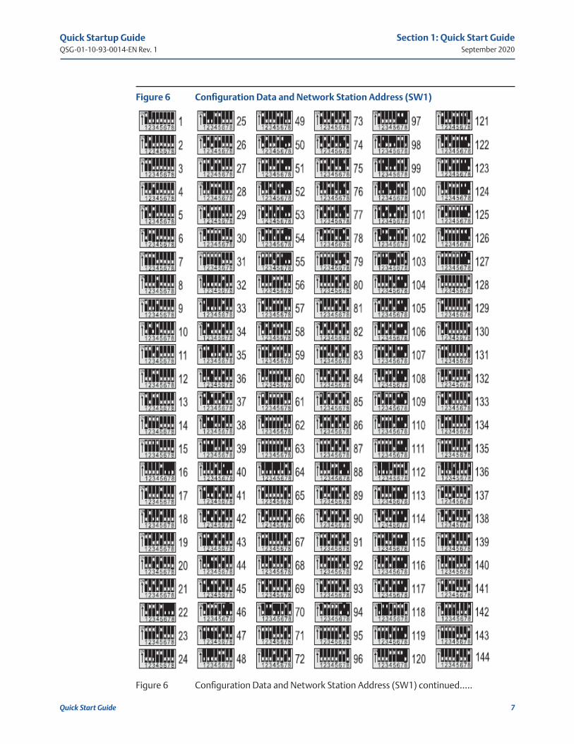
Figure 6 Configuration Data and Network Station Address (SW1)
Figure 6 Configuration Data and Network Station Address (SW1) continued.....
Quick Startup GuideQSG-01-10-93-0014-EN Rev. 1
September 2020
8
Section 1: Quick Start Guide
Quick Start Guide
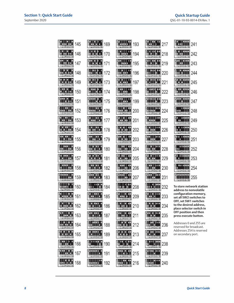
To store network station address to nonvolatile configuration memory, set all SW2 switches to OFF, set SW1 switches to the desired address, place selector switch in OFF position and then press execute button.
Addresses 0 and 255 are reserved for broadcast. Addresses 254 is reserved on secondary port.
Quick Startup GuideQSG-01-10-93-0014-EN Rev. 1
September 2020
9
Section 1: Quick Start Guide
Quick Start Guide
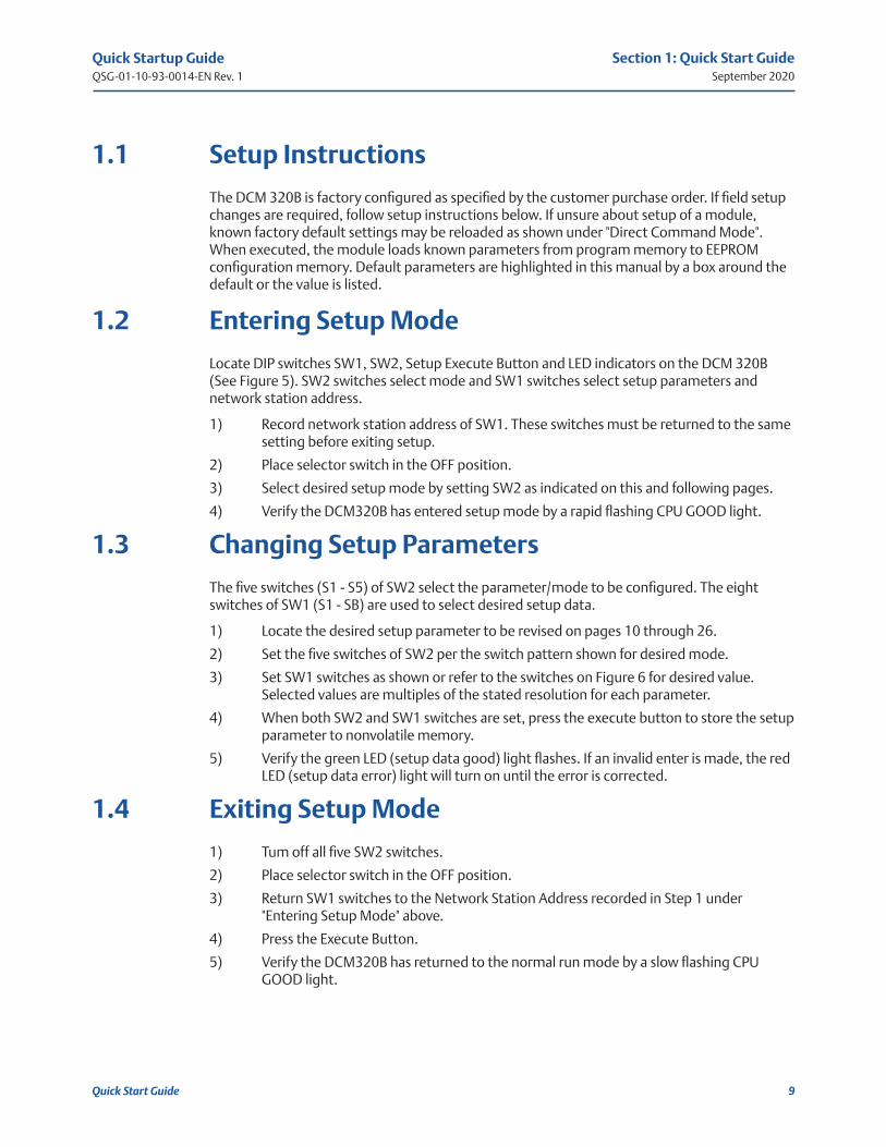
1.1 Setup Instructions
The DCM 320B is factory configured as specified by the customer purchase order. If field setup changes are required, follow setup instructions below. If unsure about setup of a module, known factory default settings may be reloaded as shown under "Direct Command Mode". When executed, the module loads known parameters from program memory to EEPROM configuration memory. Default parameters are highlighted in this manual by a box around the default or the value is listed.
1.2 Entering Setup Mode
Locate DIP switches SW1, SW2, Setup Execute Button and LED indicators on the DCM 320B (See Figure 5). SW2 switches select mode and SW1 switches select setup parameters and network station address.
1) Record network station address of SW1. These switches must be returned to the same setting before exiting setup.
2) Place selector switch in the OFF position.
3) Select desired setup mode by setting SW2 as indicated on this and following pages.
4) Verify the DCM320B has entered setup mode by a rapid flashing CPU GOOD light.
1.3 Changing Setup Parameters
The five switches (S1 - S5) of SW2 select the parameter/mode to be configured. The eight switches of SW1 (S1 - SB) are used to select desired setup data.
1) Locate the desired setup parameter to be revised on pages 10 through 26.
2) Set the five switches of SW2 per the switch pattern shown for desired mode.
3) Set SW1 switches as shown or refer to the switches on Figure 6 for desired value. Selected values are multiples of the stated resolution for each parameter.
4) When both SW2 and SW1 switches are set, press the execute button to store the setup parameter to nonvolatile memory.
5) Verify the green LED (setup data good) light flashes. If an invalid enter is made, the red LED (setup data error) light will turn on until the error is corrected.
1.4 Exiting Setup Mode
1) Tum off all five SW2 switches.
2) Place selector switch in the OFF position.
3) Return SW1 switches to the Network Station Address recorded in Step 1 under "Entering Setup Mode" above.
4) Press the Execute Button.
5) Verify the DCM320B has returned to the normal run mode by a slow flashing CPU GOOD light.
Quick Startup GuideQSG-01-10-93-0014-EN Rev. 1
September 2020
10
Section 1: Quick Start Guide
Quick Start Guide
SW2
SW2
SW2
SW1
SW1
SW1
SW1
SW1
SW1
SW1
SW1
SW1
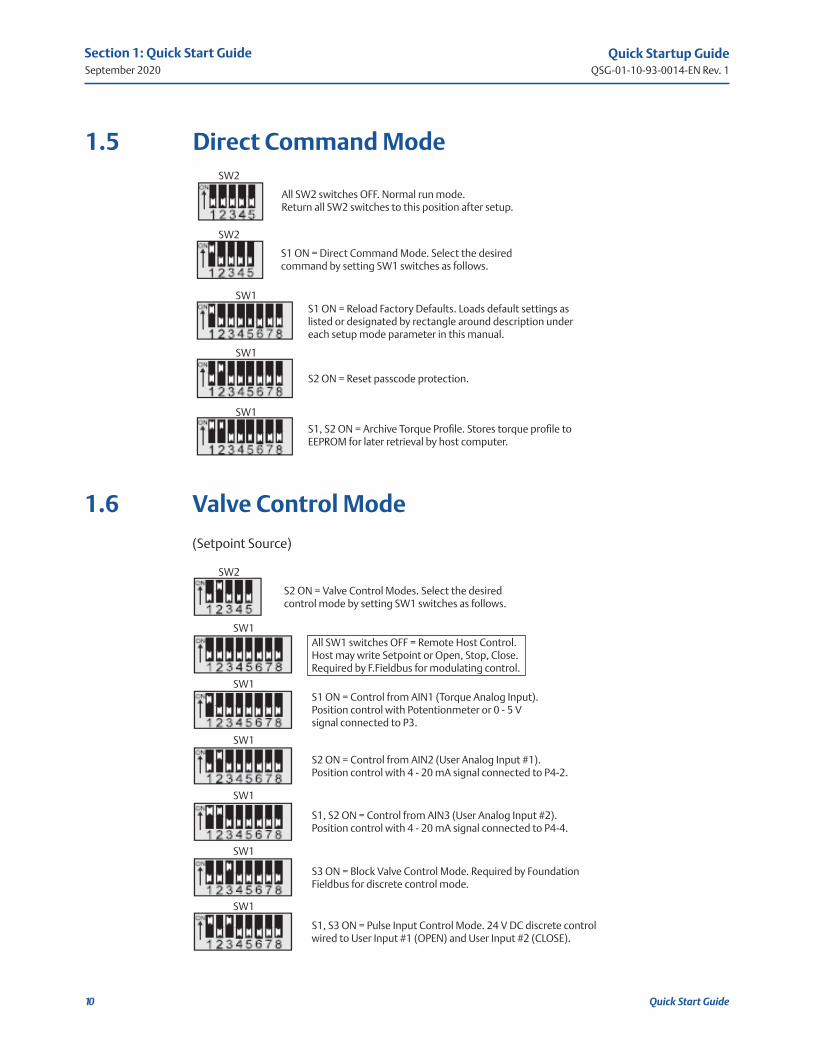
1.5 Direct Command Mode
All SW2 switches OFF. Normal run mode. Return all SW2 switches to this position after setup.
S1 ON = Direct Command Mode. Select the desired command by setting SW1 switches as follows.
S1 ON = Reload Factory Defaults. Loads default settings as listed or designated by rectangle around description under each setup mode parameter in this manual.
S2 ON = Reset passcode protection.
S1, S2 ON = Archive Torque Profile. Stores torque profile to EEPROM for later retrieval by host computer.
1.6 Valve Control Mode
(Setpoint Source)
S2 ON = Valve Control Modes. Select the desired control mode by setting SW1 switches as follows.
All SW1 switches OFF = Remote Host Control. Host may write Setpoint or Open, Stop, Close. Required by F.Fieldbus for modulating control.
S1 ON = Control from AIN1 (Torque Analog Input). Position control with Potentionmeter or 0 - 5 V signal connected to P3.
S2 ON = Control from AIN2 (User Analog Input #1). Position control with 4 - 20 mA signal connected to P4-2.
S1, S2 ON = Control from AIN3 (User Analog Input #2). Position control with 4 - 20 mA signal connected to P4-4.
S3 ON = Block Valve Control Mode. Required by Foundation Fieldbus for discrete control mode.
S1, S3 ON = Pulse Input Control Mode. 24 V DC discrete control wired to User Input #1 (OPEN) and User Input #2 (CLOSE).

Quick Startup GuideQSG-01-10-93-0014-EN Rev. 1
September 2020
11
Section 1: Quick Start Guide
Quick Start Guide
SW2
SW2
SW1
SW1
SW1
SW1
SW1
SW1
SW1
SW1
SW1
SW1
S1, S2 ON = Valve Travel Limits Mode.
All switches OFF = Open and Close Position Limits. Open to LSO and Close to LSC.
S1 ON = Enable close valve torque seat. Open to LSO and Close to TSC.
S2 ON = Enable torque backseat. Open to TSO and Close to LSC.
S1, S2 ON = Enable close torque seat and torque backseat. Open to TSO and Close to TSC.
S4 ON, Select ESD Function setup mode.
All SW1 switches OFF. Stay-Put (Stop) and do not operate ESD relay. Factory default.
S1 ON, Go closed on ESD and do not operate ESD relay.
S2 ON, Go open on ESD and do not operate ESD relay.
S1, S2 ON, Go closed on ESD and operate ESD relay.
S3 ON, Go open on ESD and operate ESD relay.
S1, S3 ON, Stay-Put and operate ESD relay. Do not operate close or open outputs.
1.7 Valve Travel Limits
1.8 ESD Function

Quick Startup GuideQSG-01-10-93-0014-EN Rev. 1
September 2020
12
Section 1: Quick Start Guide
Quick Start Guide
SW2
SW1
SW1
SW1
SW1
SW1
SW1
SW1
SW1
SW1
SW1
SW1
S2, S3 ON, Select ESD/Monitor Relay Function.
All SW1 switches OFF. Deactivate relay when an alarm is detected.
S1 ON, Activate relay when software based ESD is detected.
S2 ON, Activate relay on command from remote network host. Factory default.
S1, S4 ON, Select ESD Trigger setup mode.
All SW1 switches OFF. Disable ESD.
S1 ON, Enable ESD on command from network host. Factory default.
S2 ON, Enable ESD Relay control on local ESD discrete input.
S1, S2 ON, Enable ESD on command from host and En-able ESD Relay control on local ESD discrete input.
S3 ON, Enable ESD on loss of communications from host.
S1, S3 ON, Enable ESD on loss of command from network host and Enable ESD on loss of communications from host.
S2, S3 ON, Enable ESD Relay control on local ESD discrete input and Enable ESD on loss of communications from network host.
S1, S2, S3 ON, Enable ESD on command from network host. Enable ESD Relay control on local ESD input and Enable ESD on loss of communications from the host.
1.9 ESD/Monitor Relay Function
1.10 ESD Trigger Sources
NOTE:
At least one source must be selected, or ESD is disabled.
Quick Startup GuideQSG-01-10-93-0014-EN Rev. 1
September 2020
13
Section 1: Quick Start Guide
Quick Start Guide
SW2
SW1
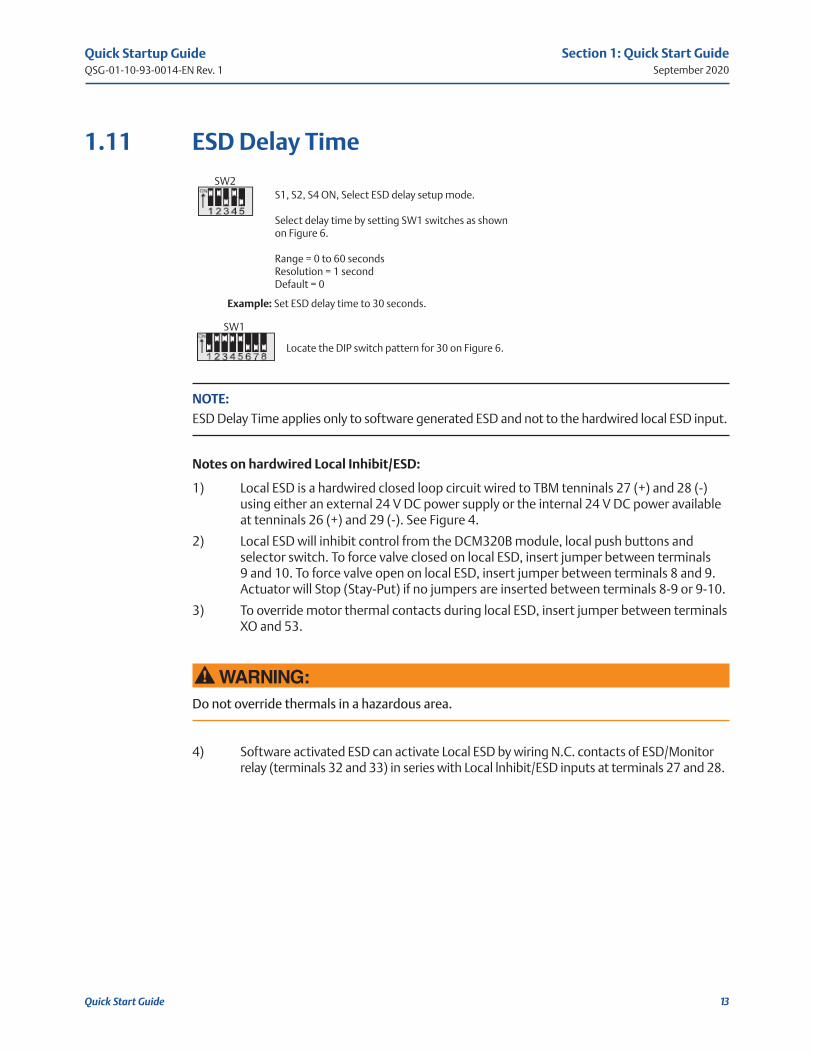
S1, S2, S4 ON, Select ESD delay setup mode.
Select delay time by setting SW1 switches as shown on Figure 6.
Range = 0 to 60 secondsResolution = 1 secondDefault = 0
Example: Set ESD delay time to 30 seconds.
Locate the DIP switch pattern for 30 on Figure 6.
1.11 ESD Delay Time
NOTE:
ESD Delay Time applies only to software generated ESD and not to the hardwired local ESD input.
Notes on hardwired Local Inhibit/ESD:
1) Local ESD is a hardwired closed loop circuit wired to TBM tenninals 27 (+) and 28 (-) using either an external 24 V DC power supply or the internal 24 V DC power available at tenninals 26 (+) and 29 (-). See Figure 4.
2) Local ESD will inhibit control from the DCM320B module, local push buttons and selector switch. To force valve closed on local ESD, insert jumper between terminals 9 and 10. To force valve open on local ESD, insert jumper between terminals 8 and 9. Actuator will Stop (Stay-Put) if no jumpers are inserted between terminals 8-9 or 9-10.
3) To override motor thermal contacts during local ESD, insert jumper between terminals XO and 53.
!WARNING:Do not override thermals in a hazardous area.
4) Software activated ESD can activate Local ESD by wiring N.C. contacts of ESD/Monitor relay (terminals 32 and 33) in series with Local lnhibit/ESD inputs at terminals 27 and 28.
Quick Startup GuideQSG-01-10-93-0014-EN Rev. 1
September 2020
14
Section 1: Quick Start Guide
Quick Start Guide
SW2
SW2
SW1
SW1
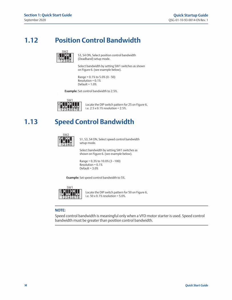
1.12 Position Control Bandwidth
S3, S4 ON, Select position control bandwidth (Deadband) setup mode.
Select bandwidth by setting SW1 switches as shown on Figure 6. (see example below).
Range = 0.1% to 5.0% (0 - 50)Resolution = 0.1%Default = 1.0%
Example: Set control bandwidth to 2.5%.
Locate the DIP switch pattern for 25 on Figure 6, i.e. 2.5 x 0.1% resolution = 2.5%.
S1, S3, S4 ON, Select speed control bandwidth setup mode.
Select bandwidth by setting SW1 switches as shown on Figure 6. (see example below).
Range = 0.3% to 10.0% (3 - 100)Resolution = 0.1%Default = 3.0%
Example: Set speed control bandwidth to 5%.
Locate the DIP switch pattern for 50 on Figure 6, i.e. 50 x 0.1% resolution = 5.0%.
1.13 Speed Control Bandwidth
NOTE:
Speed control bandwidth is meaningful only when a VFD motor starter is used. Speed control bandwidth must be greater than position control bandwidth.

Quick Startup GuideQSG-01-10-93-0014-EN Rev. 1
September 2020
15
Section 1: Quick Start Guide
Quick Start Guide
SW1
SW1
SW2
SW2
SW2
SW1
SW1
SW1
SW1
S1, S2, S3 ON, Select type of motor starter installed. Select motor started type by setting SW1 switches.
All SW1 switches OFF. Enable Electro-mechanical motor starter. Factory Default.
S1 ON, Enable Solid-State Relay (SSR) motor starter type.
S2 ON, Enable Variable Frequency Drive (VDF) motor starter type.
S3 ON, Select source for analog output. Select AO#1 source by setting SW1 switches.
All SW1 switches OFF. Enable Network Host control of analog output AO#1. Factory default.
S1 ON, Enable Position Feedback control of analog output AO#1.
S2, S3, S4 ON = Modulation Delay Timer Mode.
Select delay time by setting SW1 switches as shown on Figure 6. (see example below).
Range = 0 to 25.5 seconds (0 - 255)Resolution = 0.1 secondDefault = 0.1 second
Example: Set modulation delay time to 6 seconds.
Locate the DIP switch pattern for 60 on Figure 6, i.e. 60 x 0.1 second resolution = 6.0 seconds
1.14 Motor Starter Type
1.15 Analog Output Control
1.16 Modulation Delay Time

Quick Startup GuideQSG-01-10-93-0014-EN Rev. 1
September 2020
16
Section 1: Quick Start Guide
Quick Start Guide
SW2
SW2
SW2
SW1
SW1
SW1
1.17 Network Response Delay Time
1.17.1 Primary Network Ports A and B
S1, S2, S3, S4 ON, Select Ports A and B response delay mode.
Select delay time by setting SW1 switches as shown on Figure 6. (see example below).
Range = 8 to 60 mS (8 - 60)Resolution = 1 mSDefault = 8 mS
Example: Set response delay to 15 mS.
Locate the DIP switch pattern for 15 on Figure 6.
S5 ON, Select Ports C and D response delay mode.
Select delay time by setting SW1 switches as shown on Figure 6. (see example below).
Range = 8 to 60 mS (8 - 60)Resolution = 1 mSDefault = 8 mS
S1, S3 ON, Select Close Torque (Log-Jam) function.
All SW1 switches OFF. Disable close torque retry (Log-Jam) funstion. Factory default.
S1 ON. Enable close torque retry (Log-Jam) function.
1.17.2 Secondary Network Ports C and D
1.18 Torque Retry (Log-Jam) Control

Quick Startup GuideQSG-01-10-93-0014-EN Rev. 1
September 2020
17
Section 1: Quick Start Guide
Quick Start Guide
SW2
SW2
SW1 SW1
SW1 SW1
SW1 SW1
S1, S5 ON. Select baud rate for primary network ports A and B.
Select baud rate by setting SW1 switches as shown below. Default = 9600.
S2, S5 ON. Select baud rate for secondary network ports C and D.
Select baud rate by setting SW1 switches as shown below. Default = 19200.
All OFF = 1200
S1 = 2400
S2 = 4800 S1, 3 = 38400
S3 = 1900
S1, 2 = 9600
1.19 Network Baud Rate
1.19.1 Primary Network Ports A and B
1.19.2 Secondary Network Ports C and D

Quick Startup GuideQSG-01-10-93-0014-EN Rev. 1
September 2020
18
Section 1: Quick Start Guide
Quick Start Guide
1.20.2 Secondary Network Ports C and D
SW2
SW2
SW2
SW1
SW1
SW1
1.20 Network Parity
1.20.1 Primary Network Ports A and B
S1, 2, 5 ON. Select parity for primary network. Select parity by setting SW1 switches as shown below.
S1, 2, 5 ON. Select parity for secondary network. Select parity by setting SW1 switches as shown below.
All SW1 switches OFF = No parity
S1 = Even parity
S2 = Odd parity
S1, 3, 5 ON. Select analog input and ouput calibration mode.
Set SW1 to select the desired analog input or output calibration, apply calibration current to input or connect 4 - 20 mA meter to output and then press execute button.
1.21 Calibrate Analog I/O

Quick Startup GuideQSG-01-10-93-0014-EN Rev. 1
September 2020
19
Section 1: Quick Start Guide
Quick Start Guide
SW1
SW1
SW1
SW1
SW1
SW1
SW1
SW1
SW1
SW1
S2 ON, Set Torque analog input Zero. Input zero offset resistance/voltage.
S1, 2 ON, Set Torque analog input Span. Input full scale resistance/voltage.
S2, 3 ON, Set User #1 analog input Zero. Input 4 mA offset current.
S1, 2, 3 ON, Set User #1 analog input Span. Input 20 mA full scale current.
S2, 4 ON, Set User #2 analog input Zero. Input 4 mA offset current.
S1, 2, 4 ON, Set User #2 analog input Span. Input 20 mA full scale current.
S2, 3, 4 ON, Increase zero analog output at AO#1 while the Execute button is pressed.
S1, 2, 3, 4 ON, Decrease zero analog output at AO#1 while the Execute button is pressed.
S5 ON, Increase full scale analog output at AO#1 while the Execute button is pressed.
S1, 5 ON, Decrease full scale analog output at AO#1 while the Execute button is pressed.
1.22 Calibrate Analog Inputs
1.23 Calibrate Analog Output
Quick Startup GuideQSG-01-10-93-0014-EN Rev. 1
September 2020
20
Section 1: Quick Start Guide
Quick Start Guide
SW1
SW1
SW2
SW1
SW1
SW1
SW1
SW1
SW1
SW1
SW1
SW1
SW1
SW1
SW1
SW1
SW1
SW1
SW1
SW1
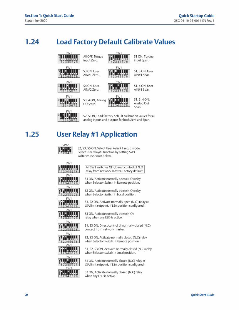
1.24 Load Factory Default Calibrate Values
All OFF. Torque input Zero.
S3 ON, User AIN#1 Zero.
S4 ON, User AIN#2 Zero.
S3, 4 ON, Analog Out Zero.
S2, 5 ON, Load factory default calibration values for all analog inputs and outputs for both Zero and Span.
S1, 3, 4 ON, Analog Out Span.
S1, 4 ON, User AIN#1 Span.
S1, 3 ON, User AIN#1 Span.
S1 ON, Tprque input Span.
S2, S3, S5 ON, Select User Relay#1 setup mode. Select user relay#1 function by setting SW1 switches as shown below.
S1 ON, Activate normally open (N.O) relay when Selector Switch in Remote position.
S2 ON, Activate normally open (N.O) relay when Selector Switch in Local position.
S1, S2 ON, Activate normally open (N.O) relay at LSA limit setpoint, if LSA position configured.
S3 ON, Activate normally open (N.O) relay when any ESD is active.
S1, S3 ON, Direct control of normally closed (N.C) contact from network master.
S2, S3 ON, Activate normally closed (N.C) relay when Selector switch in Remote position.
S1, S2, S3 ON, Activate normally closed (N.C) relay when Selector switch in Local position.
S4 ON, Activate normally closed (N.C) relay at LSA limit setpoint, if LSA position configured.
S3 ON, Activate normally closed (N.C) relay when any ESD is active.
All SW1 switches OFF, Direct control of N.O relay from network master. Factory default.
1.25 User Relay #1 Application
Quick Startup GuideQSG-01-10-93-0014-EN Rev. 1
September 2020
21
Section 1: Quick Start Guide
Quick Start Guide
SW1
SW2
SW1
SW1
SW1
SW1
SW1
SW1
SW1
SW1
SW1
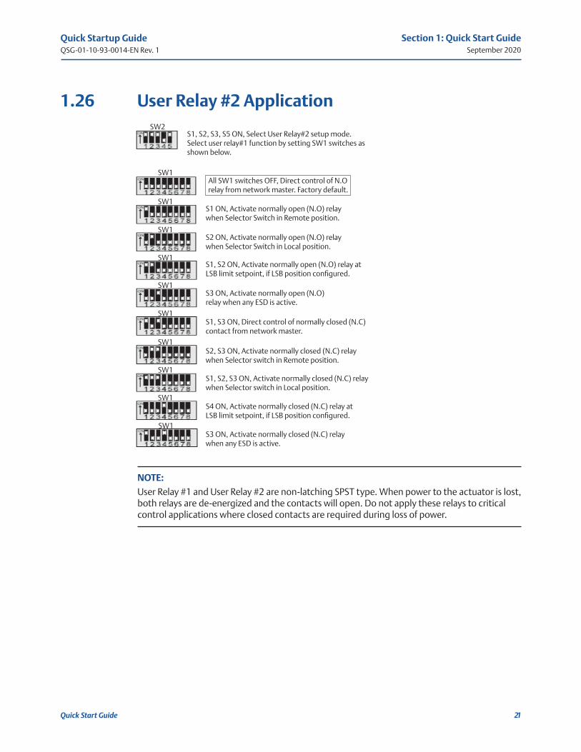
S1, S2, S3, S5 ON, Select User Relay#2 setup mode. Select user relay#1 function by setting SW1 switches as shown below.
S1 ON, Activate normally open (N.O) relay when Selector Switch in Remote position.
S2 ON, Activate normally open (N.O) relay when Selector Switch in Local position.
S1, S2 ON, Activate normally open (N.O) relay at LSB limit setpoint, if LSB position configured.
S3 ON, Activate normally open (N.O) relay when any ESD is active.
S1, S3 ON, Direct control of normally closed (N.C) contact from network master.
S2, S3 ON, Activate normally closed (N.C) relay when Selector switch in Remote position.
S1, S2, S3 ON, Activate normally closed (N.C) relay when Selector switch in Local position.
S4 ON, Activate normally closed (N.C) relay at LSB limit setpoint, if LSB position configured.
S3 ON, Activate normally closed (N.C) relay when any ESD is active.
All SW1 switches OFF, Direct control of N.O relay from network master. Factory default.
1.26 User Relay #2 Application
NOTE:
User Relay #1 and User Relay #2 are non-latching SPST type. When power to the actuator is lost, both relays are de-energized and the contacts will open. Do not apply these relays to critical control applications where closed contacts are required during loss of power.

Quick Startup GuideQSG-01-10-93-0014-EN Rev. 1
September 2020
22
Section 1: Quick Start Guide
Quick Start Guide
SW2
SW2
SW1
SW1
1.27 LSA Position Setpoint
S4, 5 ON, Select LSA position setup mode.
Select LSA by setting SW1 switches as shown on Figure 6. (see example below).
Range = 0 to 100%Resolution = 1%Default = 0 (LSA disabled)
Example: Set LSA position to 30%.
Locate the DIP switch pattern for 30 on Figure 6.
S2, 4, 5 ON, Select LSB position setup mode.
Select LSB by setting SW1 switches as shown on Figure 6. (see example below).
Range = 0 to 100%Resolution = 1%Default = 0 (LSB disabled)
Example: Set LSB position to 60%.
Locate the DIP switch pattern for 60 on Figure 6.
1.28 LSB Position Setpoint

Quick Startup GuideQSG-01-10-93-0014-EN Rev. 1
September 2020
23
Section 1: Quick Start Guide
Quick Start Guide
SW2
SW2
SW1
SW1
S2, 4, 5 ON, Select anti-water hammer setup mode.
Select anti-water hammer position by setting SW1 switches as shown on Figure 6. (see example below). This is the position that anti-water hammer is activated while the valve is closing.
Range = 0 to 100%Resolution = 1%Default = 0 (anti-water hammer disabled)
Example: Set Anti-water hammer position to 10%.
Locate the DIP switch pattern for 10 on Figure 6.
S1, 3, 4, 5 ON, Select opening duty cycle ON timer.
Select opening ON time by setting SW1 switches as shown on Figure 6. (see example below).
Range = 0 to 65 secondsResolution = 1 secondDefault = 0 (Timer disabled)
Example: Set Anti-water hammer position to 10%.
Locate the DIP switch pattern for 6 on Figure 6.
1.29 Anti-water Hammer
1.30 Opening Duty Cycle ON Timer
Quick Startup GuideQSG-01-10-93-0014-EN Rev. 1
September 2020
24
Section 1: Quick Start Guide
Quick Start Guide
SW2
SW2
SW1
SW1
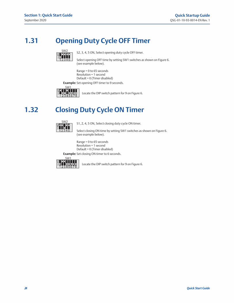
1.31 Opening Duty Cycle OFF Timer
1.32 Closing Duty Cycle ON Timer
S2, 3, 4, 5 ON, Select opening duty cycle OFF timer.
Select opening OFF time by setting SW1 switches as shown on Figure 6. (see example below).
Range = 0 to 65 secondsResolution = 1 secondDefault = 0 (Timer disabled)
Locate the DIP switch pattern for 9 on Figure 6.
Example: Set opening OFF timer to 9 seconds.
S1, 2, 4, 5 ON, Select closing duty cycle ON timer.
Select closing ON time by setting SW1 switches as shown on Figure 6. (see example below).
Range = 0 to 65 secondsResolution = 1 secondDefault = 0 (Timer disabled)
Example: Set closing ON timer to 6 seconds.
Locate the DIP switch pattern for 9 on Figure 6.

Quick Startup GuideQSG-01-10-93-0014-EN Rev. 1
September 2020
25
Section 1: Quick Start Guide
Quick Start Guide
SW2
SW1
S3, 4, 5 ON, Select closing duty cycle OFF timer.
Select closing OFF time by setting SW1 switches as shown on Figure 6. (see example below).
Range = 0 to 65 secondsResolution = 1 secondDefault = 0 (Timer disabled)
Example: Set closing OFF timer to 9 seconds.
Locate the DIP switch pattern for 9 on Figure 6.
1.33 Closing Duty Cycle OFF Timer
NOTE:
Duty cycle timers are active only when selector switch is in REMOTE position. Opening and closing speed of the valve may be adjusted (slowed) by enabling the opening or closing duty cycle timers. Duty cycle timers are available only with a solid-state or VFD starter. Anti-water hammer duty cycle is is fixed at 50% duty with one second ON time and one second OFF time for SSR and VFD starters and two seconds ON time and two seconds OFF time for electro-mechanical starter. When activated, the Anti-water hammer function overrides the closing duty cycle timer. If duty cycle or Anti-water hammer functions are used in any Anti water hammer scheme, ElM must be advised of system parameters and conditions.
Quick Startup GuideQSG-01-10-93-0014-EN Rev. 1
September 2020
26
Section 1: Quick Start Guide
Quick Start Guide
SW2
SW1
SW2
SW1
SW2
SW1
SW2
SW1
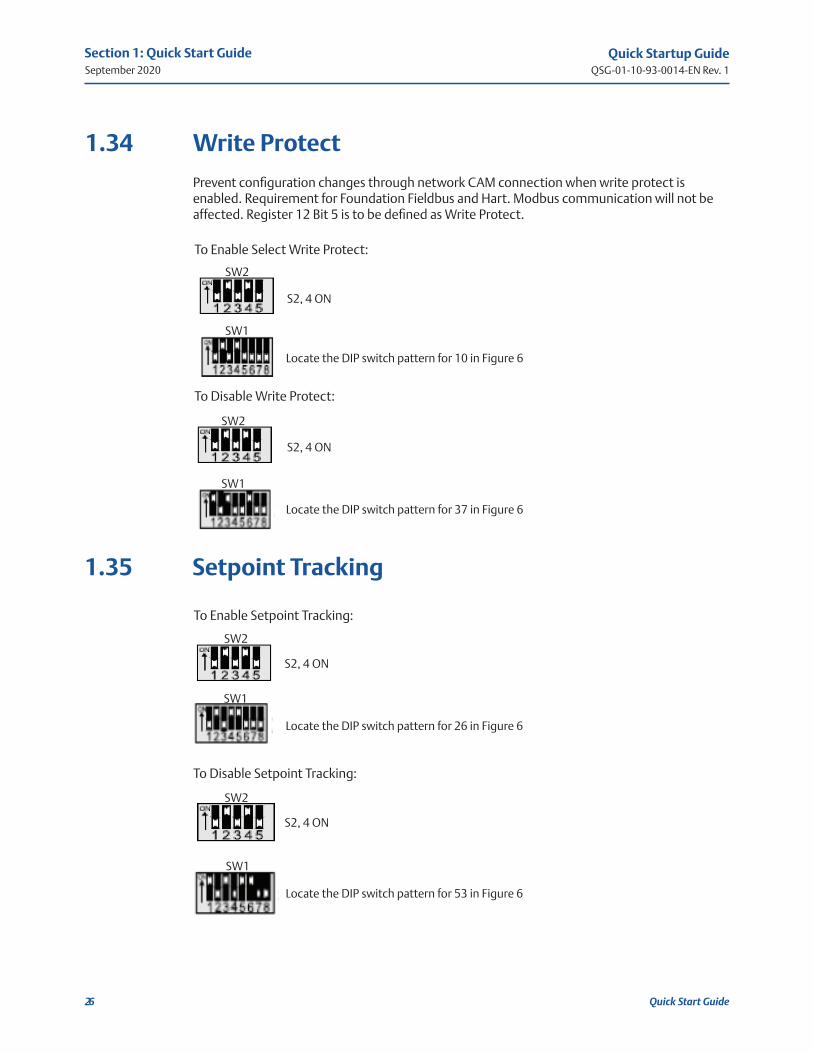
1.34 Write Protect
Prevent configuration changes through network CAM connection when write protect is enabled. Requirement for Foundation Fieldbus and Hart. Modbus communication will not be affected. Register 12 Bit 5 is to be defined as Write Protect.
To Enable Select Write Protect:
S2, 4 ON
Locate the DIP switch pattern for 10 in Figure 6
To Disable Write Protect:
S2, 4 ON
Locate the DIP switch pattern for 37 in Figure 6
To Enable Setpoint Tracking:
S2, 4 ON
Locate the DIP switch pattern for 26 in Figure 6
To Disable Setpoint Tracking:
S2, 4 ON
Locate the DIP switch pattern for 53 in Figure 6
1.35 Setpoint Tracking
Quick Startup GuideQSG-01-10-93-0014-EN Rev. 1
September 2020
27
Section 2: Modbus Memory Map Reference
Modbus Memory Map Reference
Section 2: Modbus Memory Map Reference
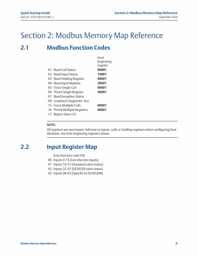
2.1 Modbus Function Codes
Hostbeginningregister
01 Read Coil Status 0000102 Read Input Status 1000103 Read Holding Register 4000104 Read Input Register 3000105 Force Single Coil 0000106 Preset Single Register 4000107 Read Exception Status08 Loopback Diagnostic Test15 Force Multiple Coils 0000116 Preset Multiple Registers 4000117 Report Slave I.D.
NOTE:
All registers are zero based. Add one to inputs, coils or holding registers when configuring host database. See host beginning registers above.
2.2 Input Register Map(Use function code 04)
00 Inputs 0-15 (Live discrete inputs)01 Inputs 16-31 (Standard valve status)02 Inputs 32-47 (DCM320 valve status)03 Inputs 48-63 (Specific to DCM320B)
Quick Startup GuideQSG-01-10-93-0014-EN Rev. 1
September 2020
28
Section 2: Modbus Memory Map Reference
Modbus Memory Map Reference
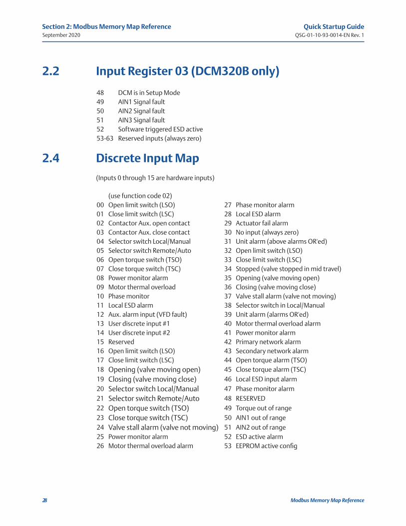
2.2 Input Register 03 (DCM320B only)
48 DCM is in Setup Mode49 AIN1 Signal fault50 AIN2 Signal fault51 AIN3 Signal fault52 Software triggered ESD active53-63 Reserved inputs (always zero)
2.4 Discrete Input Map
(Inputs 0 through 15 are hardware inputs)
(use function code 02)00 Open limit switch (LSO) 27 Phase monitor alarm01 Close limit switch (LSC) 28 Local ESD alarm02 Contactor Aux. open contact 29 Actuator fail alarm03 Contactor Aux. close contact 30 No input (always zero)04 Selector switch Local/Manual 31 Unit alarm (above alarms OR'ed)05 Selector switch Remote/Auto 32 Open limit switch (LSO)06 Open torque switch (TSO) 33 Close limit switch (LSC)07 Close torque switch (TSC) 34 Stopped (valve stopped in mid travel)08 Power monitor alarm 35 Opening (valve moving open)09 Motor thermal overload 36 Closing (valve moving close)10 Phase monitor 37 Valve stall alarm (valve not moving)11 Local ESD alarm 38 Selector switch in Local/Manual12 Aux. alarm input (VFD fault) 39 Unit alarm (alarms OR'ed)13 User discrete input #1 40 Motor thermal overload alarm14 User discrete input #2 41 Power monitor alarm15 Reserved 42 Primary network alarm16 Open limit switch (LSO) 43 Secondary network alarm17 Close limit switch (LSC) 44 Open torque alarm (TSO)18 Opening (valve moving open) 45 Close torque alarm (TSC)19 Closing (valve moving close) 46 Local ESD input alarm20 Selector switch Local/Manual 47 Phase monitor alarm21 Selector switch Remote/Auto 48 RESERVED22 Open torque switch (TSO) 49 Torque out of range23 Close torque switch (TSC) 50 AIN1 out of range24 Valve stall alarm (valve not moving) 51 AIN2 out of range25 Power monitor alarm 52 ESD active alarm26 Motor thermal overload alarm 53 EEPROM active config
Quick Startup GuideQSG-01-10-93-0014-EN Rev. 1
September 2020
29
Section 2: Modbus Memory Map Reference
Modbus Memory Map Reference
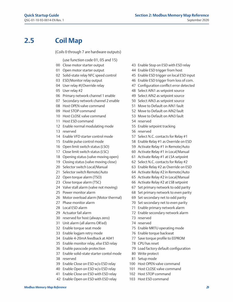
2.5 Coil Map
(Coils 0 through 7 are hardware outputs)
(use function code 01, 05 and 15)00 Close motor starter output 43 Enable Stop on ESD with ESD relay01 Open motor starter output 44 Enable ESD trigger from host02 Solid-state relay NFC speed control 45 Enable ESD trigger on local ESD input03 ESD/Monitor relay output 46 Enable ESD trigger from loss of com.04 User relay #I/Override relay 47 Configuration conflict error detected05 User relay #2 48 Select AIN1 as setpoint source06 Primary network channel 1 enable 49 Select AIN2 as setpoint source07 Secondary network channel 2 enable 50 Select AIN3 as setpoint source08 Host OPEN valve command 51 Move to Default on AIN1 fault09 Host STOP command 52 Move to Default on AIN2 fault10 Host CLOSE valve command 53 Move to Default on AIN3 fault11 Host ESD command 54 reserved12 Enable normal modulating mode 55 Enable setpoint tracking13 reserved 56 reserved14 Enable VFD starter control mode 57 Select N.C. contacts for Relay #115 Enable pulse control mode 58 Enable Relay #1 as Override on ESD16 Open limit switch status (LSO) 59 Activate Relay #1 in Remote/Auto17 Close limit switch status (LSC) 60 Activate Relay #1 in Local/Manual18 Opening status (valve moving open) 61 Activate Relay #1 at LSA setpoint19 Closing status (valve moving close) 62 Select N.C. contacts for Relay #220 Selector switch Local/Manual 63 Enable Relay #2 as Override on ESD21 Selector switch Remote/Auto 64 Activate Relay #2 in Remote/Auto22 Open torque alarm (TSO) 65 Activate Relay #2 in Local/Manual23 Close torque alarm (TSC) 66 Activate Relay #2 at LSB setpoint24 Valve stall alarm (valve not moving) 67 Set primary network to odd parity25 Power monitor alarm 68 Set primary network to even parity26 Motor overload alarm (Motor thermal) 69 Set secondary net to odd parity27 Phase monitor alarm 70 Set secondary net to even parity28 Local ESD alarm 71 Enable primary network alarm29 Actuator fail alarm 72 Enable secondary network alarm30 reserved for host (always zero) 73 reserved31 Unit alarm (all alarms OR'ed) 74 reserved32 Enable torque seat mode 75 Enable MRTU operating mode33 Enable logjam retry mode 76 Enable torque backseat34 Enable 4-20mA feedback at A0#1 77 Save torque profile to EEPROM35 Enable monitor relay, else ESD relay 78 CPU has reset36 Enable passcode protection 79 Load factory default configuration37 Enable solid-state starter contol mode 80 Write protect38 reserved 81 Setup mode39 Enable Close on ESD w/o ESD relay 100 Host OPEN valve command40 Enable Open on ESD w/o ESD relay 101 Host CLOSE valve command41 Enable Close on ESD with ESD relay 102 Host STOP command42 Enable Open on ESD with ESD relay 103 Host ESD command

Quick Startup GuideQSG-01-10-93-0014-EN Rev. 1
September 2020
30
Section 2: Modbus Memory Map Reference
Modbus Memory Map Reference
2.6 Holding Register Map
(RO = Read Only RW = Read/Write)
(Use function 03, 06 and 16)00 RW Coils 0-15 42 RW Passcode char 1(LSB) and 2(MSB)01 RO Coils 16-31 43 RW Passcode char 3(LSB) and 4(MSB)02 RW Coils 32-47 44 RO Firmware version03 RW Coils 48-63 45 RO Compatibility number04 RW Coils 64-79 46 reserved05 RO Inputs 0-15 47 reserved06 RO Inputs 16-31 48 RO Torque@ 10% valve position07 RO Valve Position 1.0% increments 49 RO Torque@ 20% valve position08 RO Valve Status inputs 32-47 50 RO Torque@ 30% valve position09 RO Valve Status inputs 16-31 51 RO Torque@ 40% valve position10 RW Analog Output (0-4095) 52 RO Torque@ 50% valve position11 RW Valve Position Setpoint (0-4095) 53 RO Torque@ 60% valve position12 RO Inputs 48-63 54 RO Torque@ 70% valve position13 RO Valve Position (0.1% increments) 55 RO Torque@ 80% valve position14 RO Position Analog Input (0-4095) 56 RO Torque@ 90% valve position15 RO Torque Analog Input (0-4095) 57 RO Torque profile @ 10%16 RO User Analog Input #1 (0-4095) 58 RO Torque profile @ 20%17 RO User Analog Input #2 (0-4095 59 RO Torque profile @ 30%18 RW Water Hammer setpoint (1-20%) 60 RO Torque profile @ 40%19 RW Modulation delay (0.1-25.5 sec) 61 RO Torque profile @ 50%20 RW ESD Delay timer (0-65.5 sec) 62 RO Torque profile @ 60%21 RW Position Bandwidth (0.1-5.0%) 63 RO Torque profile @ 70%22 RW Speed Bandwidth (0.5-10%) 64 RO Torque profile @ 80%23 RW Default Position Setpoint (0-4095) 65 RO Torque profile @ 90%24 RW Torque AIN Zero offset, raw cnts 66 RW Accumulator #1 (User Input #1)25 RW Torque AIN Span, raw AID counts 67 RW Accumulator #1 (User Input #2)26 RW User AIN1 Zero offset, raw counts 68 RW Lost COM ESD delay (mS)27 RW User AIN1 Span, raw AID counts 69 RW Stall time delay (mS)28 RW User AIN2 Zero offset, raw counts 70 RW RW Valve Travel Time/1% (mS)29 RW User AIN2 Span, raw AID counts 100 RO RO Unit I.D.30 RW A0#1 Zero offset, raw counts31 RW A0#1 Span, raw D/A counts32 RW LSA Setpoint (0-4095)33 RW LSB Setpoint (0-4095)34 RW Close ON duty cycle (0-65.5 sec)35 RW Close OFF duty cycle (0-65.5 sec)36 RW Open ON duty cycle (0-65.5 sec)37 RW Open OFF duty cycle (0-65.5 sec)38 RW Primary network baudrate39 RW Primary network response delay 40 RW Secondary network baudrate41 RW Secondary network response dela
NOTE:1) Unless otherwise specified, analog I/O is unsigned integer in range of 0-4095.
2) All time parameters are in mS.
3) Torque readings are raw AID counts.
4) Torque profile values are read from EEPROM.
5) Do not write to reserved registers.

Quick Startup GuideQSG-01-10-93-0014-EN Rev. 1
September 2020
31
Section 3: Network Installation Guide
Network Installation Guide
Section 3: Network Installation GuideStep 1: Plan the network topology
Before connecting actuators, the entire network layout should be planned. Select desired network topology from Figures 2 and 3. Topologies may be bus or E>Net or a combination of bus and E>Net. All networks may be redundant or ring or redundant rings. Limit the number of parallel connected bus units to 15 between E>Net units. Network planning should include node addressing, wire routing, terminations, and grounding.
Step 2: Select network cable
Ensure correct cable is being used. Networks require twisted pair and shielded cable with a characteristic impedance between 50 and 120 Ohms. Capacitance between conductors must be less than 30 pF/ft (98 pF/m); 10-15 pF/ft is ideal. Shielding may be aluminum foil with drain wire. Only cables with stranded conductors are recommended. Insulating and outer jacket materials must be selected for the application environment. Following are acceptable Belden or equivalent cables for most network applications.
Step 3: Route cable away from electrical interference
Network cables should enter the electrical enclosure at the bottom or lowest point near the transformer end. Route cable around the transformer end, normally in a counter clockwise direction to the top side of the TBM. Never install network cable in the same conduit with power conductors. Never route network cable through the high voltage contactor area. The cable should never lie across the TBM or hinder the protective cover of the TBM. Always use the shortest distance and keep excess cable to a minimum; 6" typical.
24AWG9841, 12.8 pF/ft
22AWG8761, 24 pF/ft
20AWG8762, 27 pF/ft
18AWG8760, 24 pF/ft
16AWG8719, 23 pF/ft
14AWG8720, 24 pF/ft
8162, 9729, and 9842 are 24AWG, 2-pair cables with <13 pF/ft

Quick Startup GuideQSG-01-10-93-0014-EN Rev. 1
September 2020
32
Section 3: Network Installation Guide
Network Installation Guide
Step 4: Observe polarity and network grounding
Each network connection is polarized + and - on wiring diagrams. Always use consistency in wiring and the use of wire colors to track polarity. The cable shield or drain wire must be connected to the designated (SH) terminal at each port of each actuator. The shield must be connected to earth ground at only one point. Some networks may require a jumper between shield connections (Terminals 22 and 23) of each actuator to carry the shield through the network. The shield connection of each actuator is isolated from earth. Do not allow the shield to touch circuits on the TBM or the metal enclosure. Use plastic electrical tape or heat shrink tubing to isolate the shield or drain wire.
Step 5: Wire preparation and connections
Screw terminals of the TBM have wire clamps that accept wires without terminals but may be applied if desired. Strip insulation back 3/8" when connecting directly to the TBM screw terminals. Do not allow wire clippings to fall on the TBM or into the actuator enclosure. Protect conductors and the shield or drain wire to prevent contact with the TBM. Use plastic electrical tape or heat shrink tubing to prevent bare conductors from contacting other circuits or earth ground.
Step 6: Wire preparation and connections
Use DCMLink or Controlinc Pocket Technician to test the network prior to connecting to a host or network master. The DCMLink is a Windows application that will run on a laptop using an RS232 to RS485 adapter or the Network Interface Unit (NIU) for connecting to the network. After all actuators are verified to operate in Local mode, test each actuator to verify all network connections and each actuator operates via the network in Remote mode.
Quick Startup GuideQSG-01-10-93-0014-EN Rev. 1
September 2020
33
Section 4: System Startup Guide
System Startup Guide
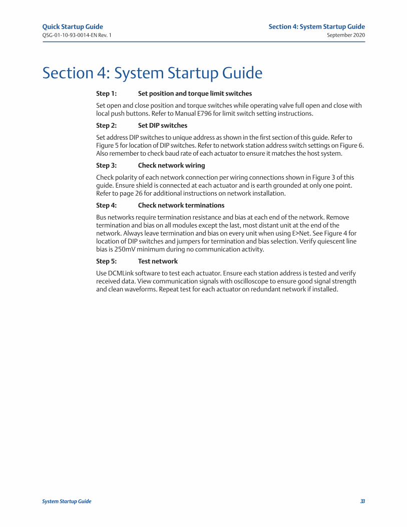
Section 4: System Startup GuideStep 1: Set position and torque limit switches
Set open and close position and torque switches while operating valve full open and close with local push buttons. Refer to Manual E796 for limit switch setting instructions.
Step 2: Set DIP switches
Set address DIP switches to unique address as shown in the first section of this guide. Refer to Figure 5 for location of DIP switches. Refer to network station address switch settings on Figure 6. Also remember to check baud rate of each actuator to ensure it matches the host system.
Step 3: Check network wiring
Check polarity of each network connection per wiring connections shown in Figure 3 of this guide. Ensure shield is connected at each actuator and is earth grounded at only one point. Refer to page 26 for additional instructions on network installation.
Step 4: Check network terminations
Bus networks require termination resistance and bias at each end of the network. Remove termination and bias on all modules except the last, most distant unit at the end of the network. Always leave termination and bias on every unit when using E>Net. See Figure 4 for location of DIP switches and jumpers for termination and bias selection. Verify quiescent line bias is 250mV minimum during no communication activity.
Step 5: Test network
Use DCMLink software to test each actuator. Ensure each station address is tested and verify received data. View communication signals with oscilloscope to ensure good signal strength and clean waveforms. Repeat test for each actuator on redundant network if installed.

Quick Startup GuideQSG-01-10-93-0014-EN Rev. 1
September 2020
34
Section 4: System Startup Guide
System Startup Guide
Step 6: Verify network master configuration
If using the Controlinc Network Master, refer to the User Manual supplied with the system for setup details. If direct connecting to your DCS, SCADA, or PLC system, refer to the manufacturer's supplied documentation. Verify network baud rate and parity match the settings of the actuators. Verify the master is configured for the total number of actuators and database matches network address assignments per actuator location on network. Take system out of test or diagnostic mode when finished.
Step 7: Test host interface
If using the Controlinc Network Master, use Modbus host test software supplied with the system to test slave port(s) of the network master. If direct connect to other host equipment, use software supplied with that equipment to test actuators. Verify database for each node and I/O point by tag name and mapping of each point to operator's screen. Operate each valve open and close or to setpoint. Test each auxilliary I/O point.
Tools:
1) Speed handle or 3/8" battery drill with 1/2" thin wall socket
2) Common screwdriver
3) Multimeter (VOM)
4) Portable oscilloscope (optional)
5) Laptop computer with Windows
6) DCMLink w/ RS485 adapter
7) Other system test software supplied with host system
8) Programming cables
9) 4-20mA calibrator for analog I/O
Quick Startup GuideQSG-01-10-93-0014-EN Rev. 1
September 2020
35
Section 5: Optional Phase Monitor
Optional Phase Monitor
GR
N
YEL
RED
P/N 84137
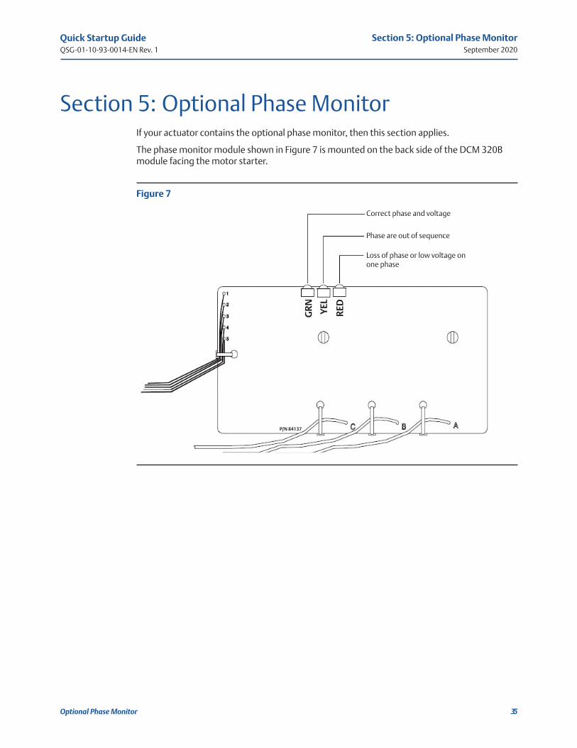
Section 5: Optional Phase MonitorIf your actuator contains the optional phase monitor, then this section applies.
The phase monitor module shown in Figure 7 is mounted on the back side of the DCM 320B module facing the motor starter.
Figure 7
Correct phase and voltage
Phase are out of sequence
Loss of phase or low voltage on one phase
Quick Startup GuideQSG-01-10-93-0014-EN Rev. 1
September 2020
36
Section 5: Optional Phase Monitor
Optional Phase Monitor
NOTE:
We advise using phase sentry mode rather than phase correction.
Phase sentry mode will cause the actuator to shut down if phases are out of sequence for proper electric motor rotation or a loss of phase is detected. Phase correction mode will cause the actuator to correct the phase sequence and continue to operate when phases are out of sequence. Either mode will cause the actuator to shut down if a loss of phase (single-phasing) is detected.
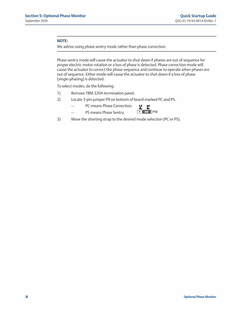
To select modes, do the following:
1) Remove TBM 320A termination panel.
2) Locate 3-pin jumper P9 on bottom of board marked PC and PS.
— PC means Phase Correction.
— PS means Phase Sentry.
3) Move the shorting strap to the desired mode selection (PC or PS).
Quick Startup GuideQSG-01-10-93-0014-EN Rev. 1
September 2020
37
Section 6: Alarm Definitions and Troubleshooting Guide
Alarm Definitions and Troubleshooting Guide
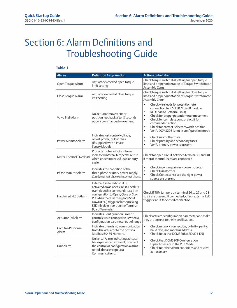
Section 6: Alarm Definitions and Troubleshooting GuideTable 1.
Alarm Definition / explanation Actions to be taken
Open Torque Alarm Actuator exceeded open torque limit setting
Check torque switch dial setting for open torque limit and proper orientation of Torque Switch Rotor Assembly Cams
Close Torque Alarm Actuator exceeded close torque imit setting
Check torque switch dial setting for close torque limit and proper orientation of Torque Switch Rotor Assembly Cams
Valve Stall Alarm No actuator movement or position feedback after 8 seconds upon a commanded movement
• Check wire leads for potentiometer connection to P2 of DCM 320B module.
• RED Lead to Bottom (Pin 3) • Check for proper potentiometer movement• Check for complete control circuit for
commanded action• Check for correct Selector Switch position• Verify DCM320B is not in configuration mode
Power Monitor Alarm
Indicates lost control voltage, or lost power, or lost phas (if supplied with a Phase Sentry Module)
• Check motor thermals• Check primary and secondary fuses• Verify primary power is present
Motor Thermal Overload
Protects motor windings from increased internal temperature rise when under increased load or duty cycle.
Check for open circuit between terminals 1 and X0 if motor thermal leads are connected
Phase Monitor AlarmIndicates the condition of the three-phase primary power supply. Can detect lost phase or incorrect phase.
• Check incoming primary power source.• Check transformer• Check Contactor to see the right power
source are present
Hardwired - ESD Alarm
External hardwired circuit is activated on an open circuit. Local ESD overrides other commands based on configuration to Open, Close or Stay Put when there is Emergency Shut Down (ESD) trigger or loose/missing ESD Inhibit Jumpers on the Terminal Board Terminals.
Check if TBM jumpers on terminal 26 to 27 and 28 to 29 are present. If connected, check external ESD trigger circuit for closed connection.
Actuator Fail AlarmIndicates Configuration Error or control circuit connection is when a configuration parameter out of range
Check actuator configuration parameter and make they are correct to their specifications.
Com No-Response Alarm
Indicates there is no communication from the actuator to the host via Modbus RS485 Network.
• Check network connection, polarity, parity, baud rate, and modbus address
• Check for active DCM320B (LEDs D1-D5)
Unit Alarm
Universal Alarm indicating actuator has experienced an event; or any of the control or configuration alarms noted above except Lost Communications.
• Check that DCM320B Configuration Dipswitches are in the Run Mode
• Check for other alarm conditions and resolve as necessary.

Quick Startup GuideQSG-01-10-93-0014-EN Rev. 1
September 2020
38
Section 7: Diagnostic Features of 320B Controlinc M2CP
Diagnostic Features of 320B Controlinc M2CP
Section 7: Diagnostic Features of 320B Controlinc M2CP
7.1 High Water Mark Torque Data (Max Torque Profile)
Design Notes for the High-Water Mark Torque Data (HWMTD) on the 320B Controlinc Electronics for M2CP actuators.
7.1.1 Test Conditions
• Firmware will update HWMTD continuously and not only after PST or FST.
• Firmware will update HWMTD when actuator is in Remote or Local and is travelling in open or close direction.
7.1.2 Test Description
1) Firmware will have a unique register block in RAM for open direction HWMTD from 0% to 100% in 1% increments.
2) Firmware will have a unique register block in RAM for close direction HWMTD from 100% to 0% in 1% decrements.
3) 51 RAM Cell locations for open and another 51 RAM Cell locations for close direction.
4) Additional cells will be assigned for Time Stamp.
5) Enable/Disable HWMTD coil 1138, Reg 1230 bit 10. This bit is Enable High logic.
6) At power-up all open and close HWMTD RAM cell locations will all be 0x0000.
7) Each cell in HWMTD will contain the largest torque value for the respective actuator stroke and direction.
7.1.3 Command to Enable HWMTD
• Host will set coil 1138 as single coil command. R1230.10
• Actuator will only do HWMTD if this bit is Enable High logic.
7.1.4 Command to Clear HWMTD Open
• When coil 1136 is set, firmware will clear all cells of HWMTD Open direction.
• Host will set coil 1136 as single coil command. R1230.8
• Time Stamp will be assigned when this command was given.
• Microcontroller Firmware will clear the coil.
7.1.5 Command to Clear HWMTD Close
• When coil 1137 is set, firmware will clear all cells of HWMTD Close direction.
• Host will set coil 1137 as single coil command. R1230.9
• Time Stamp will be assigned when this command was given.
• Microcontroller Firmware will clear the coil.

Quick Startup GuideQSG-01-10-93-0014-EN Rev. 1
September 2020
39
Section 7: Diagnostic Features of 320B Controlinc M2CP
Diagnostic Features of 320B Controlinc M2CP
7.2 Full Stroke Test (FST)
Design Notes for the Full Stroke Test implementation on the 320B Controlinc Electronics for M2CP actuators.
Table 2. Parameter values and registersParameter Value/Range Default Register
Start Position 100% or 0% 100% R1227.LTravel Range Always 100%Pause Time 1 - 30 seconds 5 Seconds R1228.LInitiated By 1 1, Network R1228.HStatus Data See Status Section R1221.H
7.2.1 Test Conditions
• Actuator must be in Remote for FST to start.
• Actuator must not be in alarm for FST to start.
• Actuator must not have any inhibits in effect for FST to start.
• Actuator will stop and FST will fail if any alarm or inhibit occurs during the test.
• Issuing a start FST command will not clear a valve stall alarm or any other alarms.
• Anti-water configuration to be ignored during FST.
7.2.2 Test Description
1) Actuator runs to 50% first if it is not between 49% and 51% at startup.
2) The actuator pauses for the user configured Pause Time, 5 seconds is default time.
3) Actuator runs to the Configured Start Position (100% or 0%).
4) The actuator pauses for the user configured Pause Time, 5 seconds is default time.
5) Actuator runs to the opposite end from the Start Position (0% or 100%).
6) The actuator pauses for the user configured Pause Time, 5 seconds is default time.
7) Actuator runs to the original Start Position (100% or 0%).
8) Test status is reported in register map.
NOTE:
If setpoint tracking is enabled in the actuator, the actuator will now run to the configured setpoint.
Quick Startup GuideQSG-01-10-93-0014-EN Rev. 1
September 2020
40
Section 7: Diagnostic Features of 320B Controlinc M2CP
Diagnostic Features of 320B Controlinc M2CP
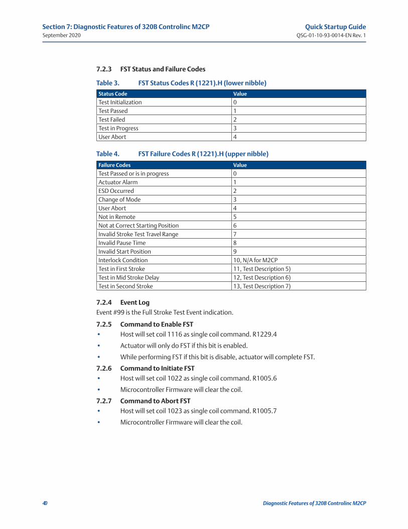
7.2.3 FST Status and Failure Codes
Table 3. FST Status Codes R (1221).H (lower nibble)
Status Code Value
Test Initialization 0Test Passed 1Test Failed 2Test in Progress 3User Abort 4
Table 4. FST Failure Codes R (1221).H (upper nibble)
Failure Codes Value
Test Passed or is in progress 0Actuator Alarm 1ESD Occurred 2Change of Mode 3User Abort 4Not in Remote 5Not at Correct Starting Position 6Invalid Stroke Test Travel Range 7Invalid Pause Time 8Invalid Start Position 9Interlock Condition 10, N/A for M2CPTest in First Stroke 11, Test Description 5)Test in Mid Stroke Delay 12, Test Description 6)Test in Second Stroke 13, Test Description 7)
7.2.4 Event Log
Event #99 is the Full Stroke Test Event indication.
7.2.5 Command to Enable FST
• Host will set coil 1116 as single coil command. R1229.4
• Actuator will only do FST if this bit is enabled.
• While performing FST if this bit is disable, actuator will complete FST.
7.2.6 Command to Initiate FST
• Host will set coil 1022 as single coil command. R1005.6
• Microcontroller Firmware will clear the coil.
7.2.7 Command to Abort FST
• Host will set coil 1023 as single coil command. R1005.7
• Microcontroller Firmware will clear the coil.

Quick Startup GuideQSG-01-10-93-0014-EN Rev. 1
September 2020
41
Section 7: Diagnostic Features of 320B Controlinc M2CP
Diagnostic Features of 320B Controlinc M2CP
7.2.8 Command to Clear FST Profile Values
• Host will set coil 1125 as single coil command. R1229.13
• Microcontroller Firmware will clear the coil.
• R7336 to 7438 will now all be 0x0000.
7.2.9 Command to Delete Archive FST Values
• Host will set coil 1119 as single coil command. R1229.7
• Microcontroller Firmware will clear the coil.
• R7226 to 7328 will now all be 0x0000.
7.2.10 Command to Archive FST Profile
• Host will set coil 1117 as single coil command. R1229.5
• Microcontroller Firmware will clear the coil.
• Firmware will save FST Open/Close profile value to flash.
• FST profile value will now be written to R7226 to 7328 as archive values.
• Look at register assignment below.
7.2.11 FST Header Profile
Table 5. FST Header Profile
Register # High Byte Low Byte Description
7330 Range Start Position 100%, 0 or 100%7331 Initiated By Pause Time Initiate = 1, Host. Pause Time: 1 - 30 seconds7332 N/A N/A7333 N/A N/A7334 Time Byte 0 Time Byte 1 Currently Time is N/A7335 Time Byte 2 Time Byte 3 Currently Time is N/A
7.2.12 Closing (100 - 0%) FST Profile, Registry
Torque at Actuator Position:
• R7336 UB LB – Torque at 1% – Torque at 0%
• R7337 UB LB – Torque at 3% – Torque at 2%
• ...
• R7385 UB LB – Torque at 99% – Torque at 98%
• R7386 UB LB – N/A – Torque at 100%
7.2.13 Opening (0 - 100%) FST Profile, Registry
Torque at Actuator Position:
• R7388 UB LB – Torque at 1% – Torque at 0%
• R7389 UB LB – Torque at 3% – Torque at 2%
• ...
• R7437 UB LB – Torque at 99% – Torque at 98%
• R7438 UB LB – N/A – Torque at 100%
Quick Startup GuideQSG-01-10-93-0014-EN Rev. 1
September 2020
42
Section 7: Diagnostic Features of 320B Controlinc M2CP
Diagnostic Features of 320B Controlinc M2CP
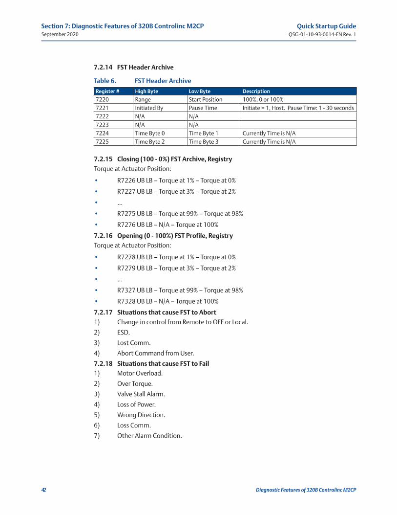
7.2.14 FST Header Archive
Table 6. FST Header Archive
Register # High Byte Low Byte Description
7220 Range Start Position 100%, 0 or 100%7221 Initiated By Pause Time Initiate = 1, Host. Pause Time: 1 - 30 seconds7222 N/A N/A7223 N/A N/A7224 Time Byte 0 Time Byte 1 Currently Time is N/A7225 Time Byte 2 Time Byte 3 Currently Time is N/A
7.2.15 Closing (100 - 0%) FST Archive, Registry
Torque at Actuator Position:
• R7226 UB LB – Torque at 1% – Torque at 0%
• R7227 UB LB – Torque at 3% – Torque at 2%
• ...
• R7275 UB LB – Torque at 99% – Torque at 98%
• R7276 UB LB – N/A – Torque at 100%
7.2.16 Opening (0 - 100%) FST Profile, Registry
Torque at Actuator Position:
• R7278 UB LB – Torque at 1% – Torque at 0%
• R7279 UB LB – Torque at 3% – Torque at 2%
• ...
• R7327 UB LB – Torque at 99% – Torque at 98%
• R7328 UB LB – N/A – Torque at 100%
7.2.17 Situations that cause FST to Abort
1) Change in control from Remote to OFF or Local.
2) ESD.
3) Lost Comm.
4) Abort Command from User.
7.2.18 Situations that cause FST to Fail
1) Motor Overload.
2) Over Torque.
3) Valve Stall Alarm.
4) Loss of Power.
5) Wrong Direction.
6) Loss Comm.
7) Other Alarm Condition.

Quick Startup GuideQSG-01-10-93-0014-EN Rev. 1
September 2020
43
Section 7: Diagnostic Features of 320B Controlinc M2CP
Diagnostic Features of 320B Controlinc M2CP
7.3 Partial Stroke Test (PST)
Design Notes for the Partial Stroke Test implementation on the 320B Controlinc Electronics for M2CP actuators.
Table 7. Parameter values and registers
Parameter Value/Range Default Register
Start Position 100% or 0% 100% R1225.LStop Position 30% 70% if at 100%30% if at 0% 5 seconds R1228.LTravel Range 1% to 30% in increment of 1% 30% R1225.HPause Time 1 - 30 seconds 5 seconds R1226.LInitiated By 1 1, Network R1226.HStatus Data See Status Section R1221.L
7.3.1 Test Conditions
• Actuator must be in Remote for PST to start.
• Actuator must not be in alarm for PST to start.
• Actuator must not have any inhibits in effect for PST to start.
• Actuator will stop and PST will fail if any alarm or inhibit occurs during the test.
• Issuing a start PST command will not clear a valve stall alarm or any other alarms.
• Anti-water configuration to be ignored during PST.
7.3.2 Test Description
1) Actuator runs to the Configured Start Position (100% or 0%)
2) Actuator pauses for the user configured Pause Time, 5 seconds is default time.
3) If configured start position is 100%, actuator will run to 70%, close PST.
4) Actuator pauses for the user configured Pause Time, 5 seconds is default time.
5) Actuator will run to 0%.
6) Actuator pauses for the user configured Pause Time, 5 seconds is default time.
7) Actuator will run to 30%, open PST.
8) Actuator pauses for the user configured Pause Time, 5 seconds is default time.
9) If configured start position is 0%, actuator will run to 30%, open PST.
10) Actuator pauses for the user configured Pause Time, 5 seconds is default time.
11) Actuator will run to 100%.
12) Actuator pauses for the user configured Pause Time, 5 seconds is default time.
13) Actuator will run to 70%, close PST.
14) Actuator pauses for the user configured Pause Time, 5 seconds is default time.
15) Either items 3-8 or 9-14 will be executed.
16) Test status is reported in register map.
Quick Startup GuideQSG-01-10-93-0014-EN Rev. 1
September 2020
44
Section 7: Diagnostic Features of 320B Controlinc M2CP
Diagnostic Features of 320B Controlinc M2CP
NOTE:
If setpoint tracking is enabled in the actuator, the actuator will now run to the configured setpoint.
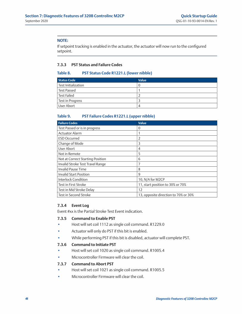
7.3.3 PST Status and Failure Codes
Table 8. PST Status Code R1221.L (lower nibble)
Status Code Value
Test Initialization 0Test Passed 1Test Failed 2Test in Progress 3User Abort 4
Table 9. PST Failure Codes R1221.L (upper nibble)
Failure Codes Value
Test Passed or is in progress 0Actuator Alarm 1ESD Occurred 2Change of Mode 3User Abort 4Not in Remote 5Not at Correct Starting Position 6Invalid Stroke Test Travel Range 7Invalid Pause Time 8Invalid Start Position 9Interlock Condition 10, N/A for M2CPTest in First Stroke 11, start position to 30% or 70%Test in Mid Stroke Delay 12 Test in Second Stroke 13, opposite direction to 70% or 30%
7.3.4 Event Log
Event #xx is the Partial Stroke Test Event indication.
7.3.5 Command to Enable PST
• Host will set coil 1112 as single coil command. R1229.0
• Actuator will only do PST if this bit is enabled.
• While performing PST if this bit is disabled, actuator will complete PST.
7.3.6 Command to Initiate PST
• Host will set coil 1020 as single coil command. R1005.4
• Microcontroller Firmware will clear the coil.
7.3.7 Command to Abort PST
• Host will set coil 1021 as single coil command. R1005.5
• Microcontroller Firmware will clear the coil.

Quick Startup GuideQSG-01-10-93-0014-EN Rev. 1
September 2020
45
Section 7: Diagnostic Features of 320B Controlinc M2CP
Diagnostic Features of 320B Controlinc M2CP
7.3.8 Command to Clear PST Profile Values
• Host will set coil 1124 as single coil command. R1229.12
• Microcontroller Firmware will clear the coil.
• R7116 to 7219 will now all be 0x0000.
7.3.9 Command to Delete Archive PST Values
• Host will set coil 1115 as single coil command. R1229.3
• Microcontroller Firmware will clear the coil.
• R7006 to 7109 will now all be 0x0000.
7.3.10 Command to Archive PST Profile
• Host will set coil 1113 as single coil command. R1229.1
• Microcontroller Firmware will clear the coil.
• Firmware will save PST Open/Close profile value to flash.
• PST profile value will now be written to R7006 to 7109 as archive values.
• Look at register assignment below.
7.3.11 PST Header Profile
Table 10. PST Header Profile
Register # High Byte Low Byte Description
7110 Range Start Position 30%, 0 or 100%7111 Initiated By Pause Time Initiate = 1, Host. Pause Time 1 - 30 seconds7112 N/A N/A7113 N/A N/A7114 Time Byte 0 Time Byte 1 Currently Time is N/A7115 Time Byte 2 Time Byte 3 Currently Time is N/A
7.3.12 Closing (100 - 70%) PST Profile, Registry
Torque at Actuator Position:
• R7116 UB LB – Torque at 1% – Torque at 0%
• R7117 UB LB – Torque at 3% – Torque at 2%
• ...
• R7166 UB LB – Torque at 99% – Torque at 98%
• R7167 UB LB – N/A – Torque at 100%
7.3.13 Opening (0 - 30%) PST Profile, Registry
Torque at Actuator Position:
• R7168 UB LB – Torque at 1% – Torque at 0%
• R7169 UB LB – Torque at 3% – Torque at 2%
• ...
• R7218 UB LB – Torque at 99% – Torque at 98%
• R7219 UB LB – N/A – Torque at 100%
Quick Startup GuideQSG-01-10-93-0014-EN Rev. 1
September 2020
46
Section 7: Diagnostic Features of 320B Controlinc M2CP
Diagnostic Features of 320B Controlinc M2CP
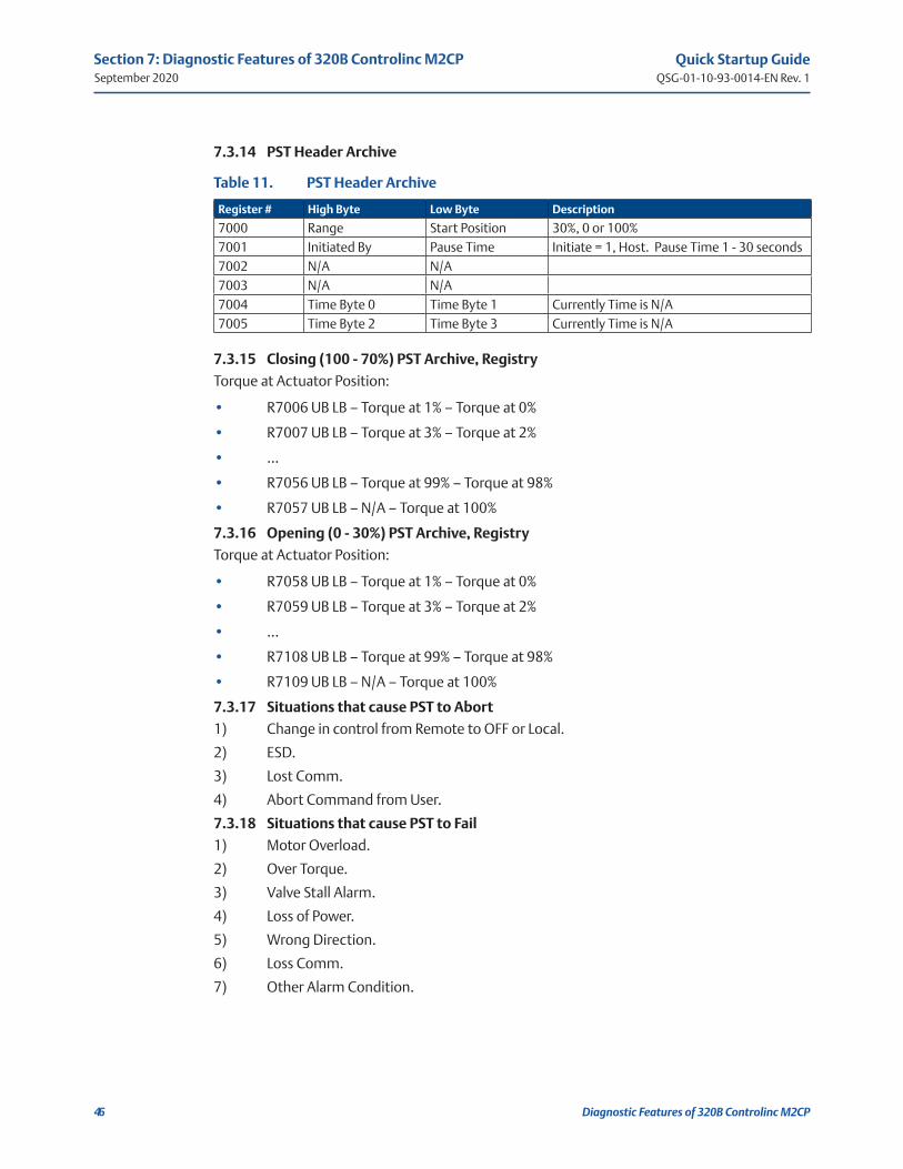
7.3.14 PST Header Archive
Table 11. PST Header Archive
Register # High Byte Low Byte Description
7000 Range Start Position 30%, 0 or 100%7001 Initiated By Pause Time Initiate = 1, Host. Pause Time 1 - 30 seconds7002 N/A N/A7003 N/A N/A7004 Time Byte 0 Time Byte 1 Currently Time is N/A7005 Time Byte 2 Time Byte 3 Currently Time is N/A
7.3.15 Closing (100 - 70%) PST Archive, Registry
Torque at Actuator Position:
• R7006 UB LB – Torque at 1% – Torque at 0%
• R7007 UB LB – Torque at 3% – Torque at 2%
• ...
• R7056 UB LB – Torque at 99% – Torque at 98%
• R7057 UB LB – N/A – Torque at 100%
7.3.16 Opening (0 - 30%) PST Archive, Registry
Torque at Actuator Position:
• R7058 UB LB – Torque at 1% – Torque at 0%
• R7059 UB LB – Torque at 3% – Torque at 2%
• ...
• R7108 UB LB – Torque at 99% – Torque at 98%
• R7109 UB LB – N/A – Torque at 100%
7.3.17 Situations that cause PST to Abort
1) Change in control from Remote to OFF or Local.
2) ESD.
3) Lost Comm.
4) Abort Command from User.
7.3.18 Situations that cause PST to Fail
1) Motor Overload.
2) Over Torque.
3) Valve Stall Alarm.
4) Loss of Power.
5) Wrong Direction.
6) Loss Comm.
7) Other Alarm Condition.

Quick Startup GuideQSG-01-10-93-0014-EN Rev. 1
NotesSeptember 2020
This page intentionally left blank

www.emerson.com
VCIOM-15747-EN ©2020 Emerson. All rights reserved.
The Emerson logo is a trademark and service mark of Emerson Electric Co.All other marks are property of their respective owners.
The contents of this publication are presented for informational purposes only, and while every effort has been made to ensure their accuracy, they are not to be construed as warranties or guarantees, express or implied, regarding the products or services described herein or their use or applicability. All sales are governed by our terms and conditions, which are available upon request. We reserve the right to modify or improve the designs or specifications of such products at any time without notice.
World Area Configuration Centers (WACC) offer sales support, service, inventory and commissioning to our global customers. Choose the WACC or sales office nearest you:
NORTH & SOUTH AMERICA 19200 Northwest FreewayHouston TX 77065USAT +1 281 477 4100
Av. Hollingsworth 325 Iporanga Sorocaba SP 18087-105BrazilT +55 15 3413 8888
ASIA PACIFIC
No. 9 Gul Road#01-02 Singapore 629361T +65 6777 8211
No. 1 Lai Yuan RoadWuqing Development AreaTianjin 301700P. R. ChinaT +86 22 8212 3300
MIDDLE EAST & AFRICA P. O. Box 17033Jebel Ali Free ZoneDubaiT +971 4 811 8100
P. O. Box 10305Jubail 31961Saudi ArabiaT +966 3 340 8650
24 Angus CrescentLongmeadow Business Estate East P.O. Box 6908 Greenstone 1616 Modderfontein Extension 5South AfricaT +27 11 451 3700
EUROPE
Holland Fasor 6Székesfehérvár 8000HungaryT +36 22 53 09 50
Strada Biffi 16529017 Fiorenzuola d’Arda (PC)ItalyT +39 0523 944 411
For complete list of sales and manufacturing sites, please visit www.emerson.com/actuationtechnologieslocations or contact us at [email protected]