ooad using uml, v. 3.0 architectural design, p. 1 copyright © 1997 by rational software corporation...
TRANSCRIPT

OOAD Using UML, v. 3.0 Architectural Design, p. 1 Copyright © 1997 by Rational Software Corporation
Architectural Design

OOAD Using UML, v. 3.0 Architectural Design, p. 2 Copyright © 1997 by Rational Software Corporation
Objectives: Architectural Design
You will be able to: List the attributes of good architectures Investigate the “4+1” view of architecture Explain the purpose of component diagrams Explain the purpose of deployment diagrams

OOAD Using UML, v. 3.0 Architectural Design, p. 3 Copyright © 1997 by Rational Software Corporation
Architectural Vision
Two traits common to virtually all successful OO projects are: The existence of a strong architectural vision The application of a well-managed, iterative and incremental
lifecycle The architecture should be simple
Common behavior achieved through common abstractions and common mechanisms

OOAD Using UML, v. 3.0 Architectural Design, p. 4 Copyright © 1997 by Rational Software Corporation
Attributes of Good Architectures
Good architectures are constructed in well-defined layers of abstraction:
Each layer represents a coherent abstraction Each layer has a well-defined and controlled interface Each layer is built upon well-defined and controlled facilities at
lower levels of abstraction There is a clear separation between the interface and implementation
of each layer Changes to the implementation of a layer do not violate
assumptions made by its clients
OOAD Using UML, v. 3.0 Architectural Design, p. 5 Copyright © 1997 by Rational Software Corporation
Developing the System Architecture
Architecture design deals with risk management Good architectures are best determined through iterative and
incremental development A small, experienced architecture team, led by a Chief Architect, should
be assigned responsibility for: Defining and maintaining the architectural integrity of the system Approving all changes to package interfaces Assessing project risks Proposing the order and content of each iteration

OOAD Using UML, v. 3.0 Architectural Design, p. 6 Copyright © 1997 by Rational Software Corporation
Different perspectives for different stakeholders End user, customer, project manager System engineer, developer, architect, tester
Multiple perspectives require multiple views Class diagrams don’t show how the system maps to hardware Hardware block diagrams don’t depict what parts of the system
are COTS
Dimensions of Software Architecture

OOAD Using UML, v. 3.0 Architectural Design, p. 7 Copyright © 1997 by Rational Software Corporation
An Architecture Requires Multiple Views
To completely describe an architecture, four views are needed: The logical view to provide a static picture of the primary classes
and their relationships The development view to show how the code is organized into
packages and libraries and the use of commercial off-the-shelf (COTS) software
The process view to show the processes and tasks The physical view to show the processors, devices, and links in
the operational environment Finally, a scenario view explains how the other four views work
together

OOAD Using UML, v. 3.0 Architectural Design, p. 8 Copyright © 1997 by Rational Software Corporation
The “4+1 View” Model
Development View
Process View Physical View
Scenarios
Logical View
Functionality
End-Users
Software Management,Reuse, Portability
Software Engineers
Performance, Availability,
Fault Tolerance
System Integrators
Performance, Availability, Fault Tolerance, Scalability,
Delivery and Installation
System Engineers
Understandability Usability

OOAD Using UML, v. 3.0 Architectural Design, p. 9 Copyright © 1997 by Rational Software Corporation
Logical View
The logical view of architecture addresses the functional requirements of the system
What the system will provide in terms of services to its users Provides a static picture of the primary classes and their relationships The logical view is captured in class diagrams which contain the
packages, classes, and relationships that represent the key abstractions of the system under development

OOAD Using UML, v. 3.0 Architectural Design, p. 10 Copyright © 1997 by Rational Software Corporation
Global Logical Packages
Certain packages are used by all other packages Foundation classes
Sets, lists, queues, etc. Error handling classes
These packages are marked global
FoundationClasses
global

OOAD Using UML, v. 3.0 Architectural Design, p. 11 Copyright © 1997 by Rational Software Corporation
Dependency Implications
Some of the implications of package dependency are: Whenever a change is made to the supplier package, the Client
package must, potentially, be recompiled and retested The Client package cannot be reused independently because it
depends on the supplier package
ClientPackage SupplierPackage

OOAD Using UML, v. 3.0 Architectural Design, p. 12 Copyright © 1997 by Rational Software Corporation
Avoiding Circular Dependencies
It is desirable that the package hierarchy be acyclic This means that the following situation should be avoided (if possible)
Package A uses package B which uses package A Such a circular dependency means that packages A and B will
effectively have to be treated as a single package Circles wider than two packages must also be avoided
e.g., package A uses package B which uses package C which uses package A
Circular dependencies may be able to be broken by splitting one of the packages into two smaller packages

OOAD Using UML, v. 3.0 Architectural Design, p. 13 Copyright © 1997 by Rational Software Corporation
Circular Dependency in the Registration System
Interfaces Business Rules
Changed toIncomingInterfaces Business
Rules
Outgoing Interfaced

OOAD Using UML, v. 3.0 Architectural Design, p. 14 Copyright © 1997 by Rational Software Corporation
Development View
The development (or component) view of architecture is concerned with the actual software module organization within the development environment
Component diagrams are created to show the (developmental) packages and components that make up the system under development
Shows the allocation of classes to components Shows the allocation of components to packages
The packages are organized in a hierarchy of layers where each layer has a well defined interface

OOAD Using UML, v. 3.0 Architectural Design, p. 15 Copyright © 1997 by Rational Software Corporation
Component
A component is a unit of source code that serves as a building block for the physical structure of a system
Stereotypes (with alternate icons) may be used to define specific kinds of components.
Examples: exe, dll, main programs, headers, modules, forms Group classes in a component that either have a cooperative function
or that need to be in close proximity for implementation efficiency Component notation:
Component name

OOAD Using UML, v. 3.0 Architectural Design, p. 16 Copyright © 1997 by Rational Software Corporation
Component Diagram
A component diagram shows the allocation of classes and objects to implementation components as well as their compilation dependencies
Name1
Name3
Name2
Name1
Name2

OOAD Using UML, v. 3.0 Architectural Design, p. 17 Copyright © 1997 by Rational Software Corporation
Component Diagrams
A name is required for each component; this name typically denotes the simple name of the corresponding physical file in the development workspace
The only relationship is a compilation dependency, represented by a directed dashed line pointing to the module upon which the dependency exists
In C++, a compilation dependency is indicated by #include directives There may be no cycles within a set of compilation dependencies

OOAD Using UML, v. 3.0 Architectural Design, p. 18 Copyright © 1997 by Rational Software Corporation
Example: Component Diagram
Curriculum Curriculum
Course Course
OOAD Using UML, v. 3.0 Architectural Design, p. 19 Copyright © 1997 by Rational Software Corporation
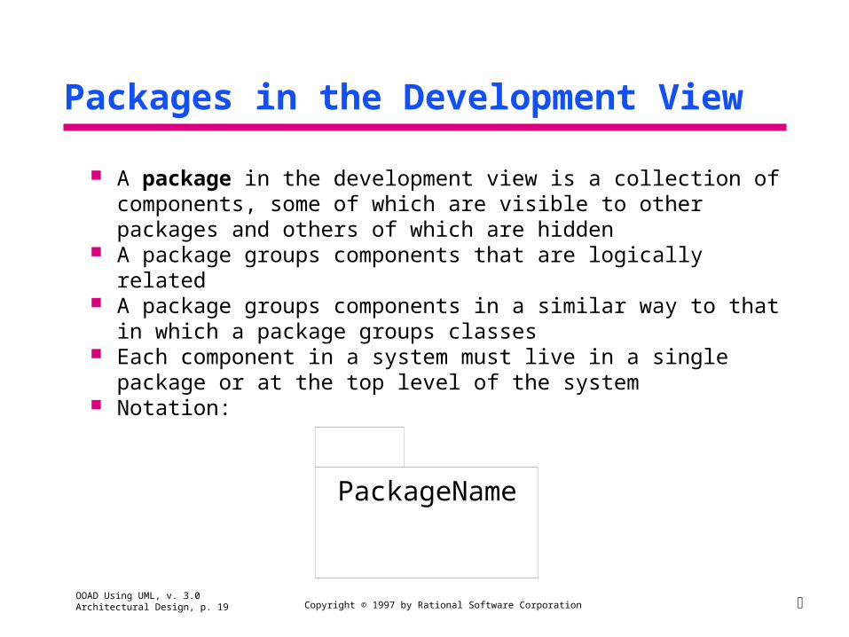
Packages in the Development View
A package in the development view is a collection of components, some of which are visible to other packages and others of which are hidden
A package groups components that are logically related A package groups components in a similar way to that in which a
package groups classes Each component in a system must live in a single package or at the top
level of the system Notation:
PackageName

OOAD Using UML, v. 3.0 Architectural Design, p. 20 Copyright © 1997 by Rational Software Corporation
Top-level Component Diagrams
A top-level component diagram is a family of packages connected by directed links that represent dependencies
Example:
MFC RegistrationUserInterface
RegistrationSystem

OOAD Using UML, v. 3.0 Architectural Design, p. 21 Copyright © 1997 by Rational Software Corporation
Correspondence Between Packages in the Logical and Development Views
In general, a package in the logical view can correspond directly to a package in the development view
The logical structure and the physical structure may vary for the following reasons:
Packages in the logical view are merged, e.g., to keep closely-communicating objects together for implementation
Packages in the development view are added to implement low-level functionality not represented during analysis
The work breakdown structure of the development team influences the allocation of packages and components in the development view

OOAD Using UML, v. 3.0 Architectural Design, p. 22 Copyright © 1997 by Rational Software Corporation
Example: Correspondence Between Logical and Physical Structure
Logical View Top-Level Diagram Development View Top-Level Diagram
MFC RegistrationUserInterface
RegistrationSystem
GuiWidgets RegistrationUserInterface
RegistrationSystem
OOAD Using UML, v. 3.0 Architectural Design, p. 23 Copyright © 1997 by Rational Software Corporation
Process View
The process view of architecture focuses on process decomposition This view shows the allocation of components to processes
The component diagram is updated to show the allocation of components to processes
The process view addresses the system’s availability, reliability, performance, system management, synchronization

OOAD Using UML, v. 3.0 Architectural Design, p. 24 Copyright © 1997 by Rational Software Corporation
Process Components
Executables and linked libraries are represented as components in UML
Package specification (DLL) Task specification (EXE)
Package specification (DLL) Task Specification (EXE)

OOAD Using UML, v. 3.0 Architectural Design, p. 25 Copyright © 1997 by Rational Software Corporation
Component Diagram for a Process
Each component may depend on other components
Name1Name2
Name1Name2
MyProcess.exe
OOAD Using UML, v. 3.0 Architectural Design, p. 26 Copyright © 1997 by Rational Software Corporation
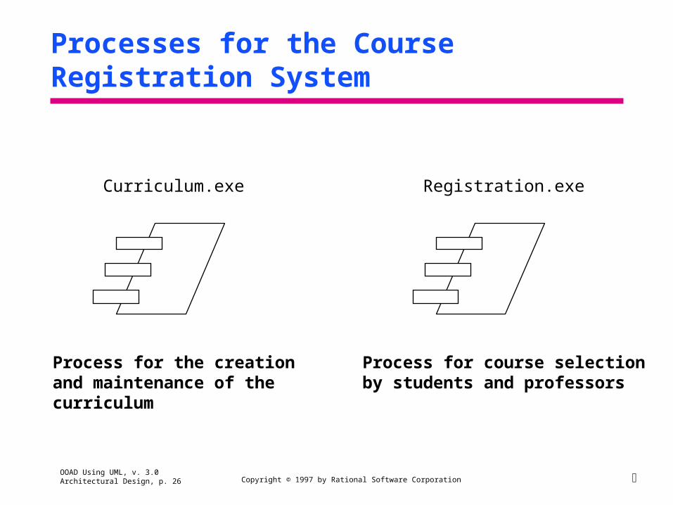
Processes for the Course Registration System
Curriculum.exe Registration.exe
Process for the creationand maintenance of the curriculum
Process for course selectionby students and professors

OOAD Using UML, v. 3.0 Architectural Design, p. 27 Copyright © 1997 by Rational Software Corporation
Physical View
The physical view of architecture maps processes to processing nodes
Requirements such as throughput, performance, and fault-tolerance are taken into account
Deployment diagrams are created to show the different nodes (processors and devices) in the system
OOAD Using UML, v. 3.0 Architectural Design, p. 28 Copyright © 1997 by Rational Software Corporation
Deployment Diagrams
A deployment diagram shows the allocation of processes to nodes in the physical view of a system
Processors and devices are common stereotypes of Node. Nodes are connected in a diagram that reflects the communication
paths between them The essential elements of a deployment diagram are nodes and their
connections

OOAD Using UML, v. 3.0 Architectural Design, p. 29 Copyright © 1997 by Rational Software Corporation
Notation for Deployment Diagrams
A node is a run-time physical object representing computational resources
A connection indicates communication, usually by means of direct hardware coupling
node connection
name label
OOAD Using UML, v. 3.0 Architectural Design, p. 30 Copyright © 1997 by Rational Software Corporation
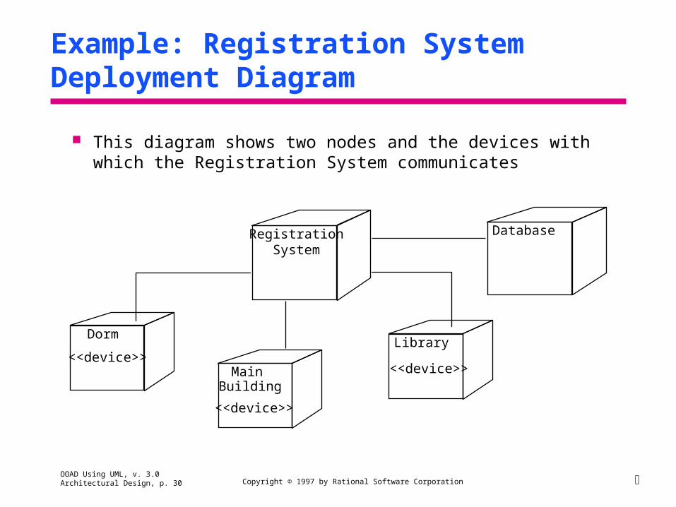
Example: Registration System Deployment Diagram
This diagram shows two nodes and the devices with which the Registration System communicates
RegistrationSystem
Database
Dorm
Main Building
Library<<device>>
<<device>>
<<device>>

OOAD Using UML, v. 3.0 Architectural Design, p. 31 Copyright © 1997 by Rational Software Corporation
Processes
A process is the execution of one thread of control of an (OO) program or system
A large system can be broken into multiple processes or threads of control
Objects are assigned to processes (their assignments can be dynamic) Processes are assigned to processors (the set of processes can be
dynamic) Notation:
process 1, process 2, ... process n
ProcessorName
OOAD Using UML, v. 3.0 Architectural Design, p. 32 Copyright © 1997 by Rational Software Corporation
Mapping Development Packages to Executable Processes
Mapping development packages to executable processes involves understanding the system topology and system priorities including:
Processor architecture, speed and capacity Keeping class associations together to minimize interprocess
communication (IPC) IPC strategy -- client/supplier or other? Distributed processing techniques
Must resolve issues involving multiple hardware processors or distributed systems during system design

OOAD Using UML, v. 3.0 Architectural Design, p. 33 Copyright © 1997 by Rational Software Corporation
Mapping Executable Processes to Hardware
Processes must be assigned to a hardware device for execution Among the considerations are:
Response time and system throughput Communication bandwidth/capacity Physical location of hardware required Distributed processing needs Processor overloading or balance in a distributed system Fault tolerance . . .

OOAD Using UML, v. 3.0 Architectural Design, p. 34 Copyright © 1997 by Rational Software Corporation
Scenarios
Scenarios are the glue that hold the four views together Drivers for the architecture design
Abstractions of large, complex requirements Identification of critical interfaces Force designers to focus on concrete issues
They demonstrate and validate the logical, process, development, and physical views of the architecture

OOAD Using UML, v. 3.0 Architectural Design, p. 35 Copyright © 1997 by Rational Software Corporation
Sample Scenarios
Development view Port to new platform
Logical view Message change impact Replacement of custom objects with COTS objects
Process view Peak loading overhead Critical thread transaction
Physical view Node failure Node off-line for preventive maintenance

OOAD Using UML, v. 3.0 Architectural Design, p. 36 Copyright © 1997 by Rational Software Corporation
How Is the Architecture Documented?
The architecture is documented in an architecture document Approximately 100 pages for a large system
The document includes: A textual description of the architectural philosophy (the views)
and the key driving requirements Tradeoffs made and alternatives considered A top-level view of the logical view (5-50 key classes) Architecture-specific scenarios Top-level views of the development, process and physical views The key mechanisms

OOAD Using UML, v. 3.0 Architectural Design, p. 37 Copyright © 1997 by Rational Software Corporation
Exercise: Architecture Design
Discuss architecture considerations for the problem Add packages to the model as needed

OOAD Using UML, v. 3.0 Architectural Design, p. 38 Copyright © 1997 by Rational Software Corporation
Summary: Architectural Design
The purpose of the design phase is to create an architecture for the implementation and establish the common tactical policies that must be used throughout the system
The attributes of good architectures are: Good architectures are constructed in well-defined layers of
abstraction There is a clear separation between the interface and
implementation of each layer The architecture is simple

OOAD Using UML, v. 3.0 Architectural Design, p. 39 Copyright © 1997 by Rational Software Corporation
Summary: Architectural Design
The logical view of architecture addresses the functional requirements of the system
Class diagrams which represent the key abstractions of the system
The process view of architecture addresses the system’s availability, reliability, scalability, integrity, performance, system management, and synchronization
System is decomposed into a set of independent tasks which are grouped into processes
The development view of architecture addresses the software organization of the system
Component diagrams are created to show the packages and components that make up the system

OOAD Using UML, v. 3.0 Architectural Design, p. 40 Copyright © 1997 by Rational Software Corporation
Summary: Architectural Design
The physical view of architecture maps software to processing nodes Deployment diagrams are created to show the different
processors and devices in the system Scenarios demonstrate and validate the logical, process, development,
and physical views of architecture

OOAD Using UML, v. 3.0 Architectural Design, p. 41 Copyright © 1997 by Rational Software Corporation