ooperationperation mmanualanualpeople.bath.ac.uk/gp304/cem/explorermanual_600187.pdf · the cem...
TRANSCRIPT

1
Op erationOperationM anualManual
600187Rev. 1
4872
96
2
Copyright 2007 by CEM CorporationAll Rights Reserved
This manual contains proprietary information, which shall notbe reproduced or transferred to other documents or disclosed to others
without prior written permission of CEM Corporation.
CEM is a registered trademark of CEM Corporation.Discover is a registered trademark of CEM Corporation.Explorer is a registered trademark of CEM Corporation.
Patents Pending
CEM CorporationPOB 200
3100 Smith Farm RoadMatthews, North Carolina 28106-0200
(704) 821-7015 (phone) 704-821-7894 (fax)
[email protected] (email)www.cem.com (web site)
Manufactured in the
United States of America
600187Rev. 05/07
3
Table of Contents
Operating Precautions ..................................................................................................................................................... 5Warnings and Cautions ................................................................................................................................................... 6Introduction ...................................................................................................................................................................... 7System Installation .......................................................................................................................................................... 9 Installation Site ........................................................................................................................................................... 9 Unpacking................................................................................................................................................................... 9 Explorer System Setup ...............................................................................................................................................14 Explorer Screen ..........................................................................................................................................................17 Keyboard Operation Shortcuts ...................................................................................................................................19 Adapter Calibration .....................................................................................................................................................20 Rack Position Setup ...................................................................................................................................................24 35 mL Vessel Offset Calibration ............................................................................................................................27Create Method .................................................................................................................................................................30 Standard Control ........................................................................................................................................................31 Dynamic Control .........................................................................................................................................................31 Power Cycling Control ................................................................................................................................................31 Fixed Power Control ...................................................................................................................................................31 SPS Control ................................................................................................................................................................31Edit Method .....................................................................................................................................................................33Delete Method .................................................................................................................................................................35Add Method to Explorer Rack..........................................................................................................................................36Removed Method(s) from Explorer Rack ........................................................................................................................36Save Explorer (Method) Sequence .................................................................................................................................36Instrument Operation .......................................................................................................................................................37Method Data ....................................................................................................................................................................42 Graph Data .................................................................................................................................................................44 Generate Report .........................................................................................................................................................45 Search Data................................................................................................................................................................45 Dave Data to File ........................................................................................................................................................45Maintenance, Troubleshooting and Service ....................................................................................................................46 Routine Maintenance and Cleaning ...........................................................................................................................46 Interlocks ...............................................................................................................................................................46 Cavity.....................................................................................................................................................................46 APD .......................................................................................................................................................................46 Microwave Leakage Measurement.............................................................................................................................48 Troubleshooting Guide ...............................................................................................................................................49 Firmware Update ........................................................................................................................................................50 Computer Setup .........................................................................................................................................................51 Repair and Service .....................................................................................................................................................54 Vessel Failure Cleanup Procedure .............................................................................................................................55 Spill Tray Cleaning......................................................................................................................................................55 Spill Cup Cleaning or Replacement............................................................................................................................56Ordering Information........................................................................................................................................................57Specifi cations ..................................................................................................................................................................58
Warranty ..........................................................................................................................................................................59

4

5
Operating PrecautionsThe Explorer System™ must be grounded. In the event of an electrical short circuit, grounding reduces the risk of electric shock by providing an escape wire for electric current. This instrument is equipped with a cord having a grounding wire with a grounding plug. The plug must be plugged into an outlet that is properly installed and grounded. Consult a qualifi ed electrician or service technician if the grounding instructions are not completely understood or if doubt exists as to whether the instrument is properly grounded. If it is necessary to use an extension cord, use only a 3-wire extension cord that has a 3-blade grounding plug and a 3-slot receptacle that will accept the plug from the instrument. The marked rating of the extension cord must be equal to or greater than the electrical rating of the instrument.
The possibility of instrument-induced electromagnetic interference (EMI) is minimal if the instrument is operated as outlined in this manual. The instrument should not be placed close to any electrical device susceptible to EMI. The manufacturer suggests that the user post a sign warning pacemaker wearers that a microwave device is in operation. If the instrument is suspected of inducing EMI, a microwave leakage measurement should be performed as outlined on pages 45-46. Leakage measured above the legal limit of 5 mW/cm2 should be reported to the CEM Service Department.
Cardiac pacemakers require magnets to control their operation during checkout. If the instrument is equipped with an optional electro-magnetic sample stirrer, which contains very high static magnetic fi elds, some danger exists if a pacemaker is positioned in close prox-imity of the instrument cavity. If the instrument is suspected of interfering with the operation of a pacemaker, the instrument should be turned off or the pacemaker wearer should move away from the instrument.
This instrument utilizes high voltages and microwave radiation. Only those trained in repair and maintenance of high voltage and microwave power systems should perform instrument service and repair.
Use of the Explorer instrument in any manner not specifi ed by CEM Corporation could render the instrument operation unsafe for the operator.
The Discover module of this instrument complies with United States Code of Federal Regulations 21CFR Part 1030.10 (C) for micro-wave leakage. A verifi cation report is on fi le. This instrument complies with FCC Requirements in the United States Code of Federal Regulations (47CFR Part 18) – Industrial, Scientifi c and Medical (ISM) Equipment – emissions requirements. A verifi cation report is on fi le.
6
Warnings and CautionsWarnings, cautions and notes are included throughout this manual and should be read thoroughly and strictly followed.
WARNING: A warning is inserted for essential information used to emphasize dangerous or hazardous conditions to the operation, cleaning and maintenance of the instrument which may result in personal injury.
CAUTION: A caution is inserted for essential information used to emphasize procedures which, if not strictly followed, may result in damage or destruction to the instrument or improper instrument operation.
NOTE: A note is inserted for emphasis of procedures or conditions that may otherwise be misinterpreted or overlooked and to clarify possible confusing situations.
WARNING
If damage to the instrument is noted upon receipt, do not attempt to operate the instrument.
This instrument utilizes high voltages and microwave radiation. Only technicians trained in repair and maintenance of high voltage and microwave power systems should perform instrument service and repair.
Proper precautions must be taken to avoid contact with solvents or solvent vapors. Protective gear should be worn as outlined in the user’s safety program for hazardous materials and the reagent manufacturer’s material safety data sheet. Refer to these guidelines for proper handling and disposal of reagents.
Never modify the attenuator access port or insert metallic objects such as wire into the port. Serious microwave leakage and/or electrical shock may result. The access port of the Discover is electrically grounded to the microwave cavity and is designed to prevent leakage of microwave energy.
Cardiac pacemakers require magnets to control operation during checkout. Because the Discover System is equipped with an variable-speed, electromagnetic sample stirrer, some danger exists if a pacemaker is positioned in close proximity to the instrument cavity. If the instrument is suspected of interfering with the operation of a pacemaker, the instrument should be turned off or the pacemaker wearer should move away from the instrument.
Refer to the manufacturer’s safety data sheet and the user’s safety program for proper handling and disposal procedures for any solvent used.
To prevent the possibility of severe burns, ensure that insulated gloves and protective gear as outlined in the user’s safety program are worn during instrument operation.
Disconnect the instrument from the AC power source prior to performing any service procedure.
CAUTION
The pressure control systems are usable only with CEM supplied vessels and caps.
Prior to using any cleaning or decontamination method except those recommended by the equipment manufacturer, the user should check with the manufacturer that the proposed method will not damage the equipment.

7
Introduction
The CEM Automated Synthesis Systems, Models Explorer™ 48, 72, 96, are designed to add automated reaction handling capabilities to the Discover™ instrument. The Focused™ Microwave family of instruments enhance the ability to perform chemical reactions under controlled conditions on a laboratory scale. These systems facilitate either homogeneous or heterogeneous solution phase chemistry, solid phase chemistry or chemistry conducted on solid supports. They accom-modate vessels ranging in volume from 5mL to 125mL for reactions performed under atmospheric conditions and 10mL, 35 mL and 4 mL sealed vessels for reactions performed at elevated temperatures and pressures. Primary uses of the Explorer and/or Discover are in the discovery and lead optimization phases of the drug development process.
Microwave energy is applied to the vessel contents (reactants, catalysts, salts, solvents and/or solid supports) to acceler-ate the chemical reaction. The microwave absorption properties of some liquid and solid materials, due to their polar and ionic characteristics, have the capability to signifi cantly enhance chemical reactions relative to traditional energy applica-tion (heating) techniques. The microwave interaction properties with the reactants, intermediates, catalysts, solid supports and salts provide unique opportunities for the synthetic chemist.
The Explorer System consists of: • Discover Module • A continuous microwave power delivery system with operator selectable power output from 0 - 300 watts programmable in 1-watt increments. • A self-adjusting, single mode microwave cavity that is manually accessed via multiple attenuator ports. • A 256 x 128 graphics display and on-board computer for programming and operational control of the system. The memory will store and recall methods. • 3 safety interlocks and an interlock monitoring system to prevent microwave emission when the attenuator port is not properly installed. • One (1) serial port for optional feature connections (1 RS 232). • Two (2) ethernet ports for computer interface and network connection (optional confi guration). • One RJ-11 port for peripheral connection. • An accessory kit. • Two (2) USB slots. • Infrared Temperature Control System – This temperature control system uses a non-contact, infrared sensor to measure temperature. It is located below the microwave cavity fl oor and measures the temperature on the bottom of the vessel. The sensor is vessel volume independent and is used in a feedback loop with the on- board computer to control the temperature rise rate and control point of the vessel contents. Temperature is programmable from 0 oC to 300 oC. • Stirring Option - The stirring option consists of an electromagnetic plate located below the fl oor of the microwave cavity. “Stirring” occurs when the magnetic fi eld couples with a stir bar in the vessel. The method setup enables the stirring feature and the stirring speed. Standard Tefl on-coated stir bars appropriate to the vessel size are used. • Cooling Option – The cooling option consists of necessary valves and ports to direct a cooling gas (either nitrogen or “clean” air) onto the vessel in the system cavity. This option will decrease the temperature of a 2mL solution in a 10mL Pyrex reaction vessel from ~150 ºC to ~50 ºC in less than 120 seconds. Method setup enables the cooling feature. • Explorer Automation Module • An X, Y table that retrieves and delivers 10 mL or 35 mL reaction vessels to the microwave chamber. • Independent Vessel Racks (4 for Explorer 48) (6 for Explorer 72) (8 for Explorer 96); to accommodate twelve 10 mL or six 35 mL vessels. • A Z-axis mechanism that integrates a reaction vessel gripper to manipulate vessels. • An external controller (computer) (optional purchase from CEM Corporation). • Application Software (Synergy software is required to operate the Explorer module.) • An accessory kit.
8
Optional features include:• Fiber Optic Temperature Control System – This optional temperature control system, for use with large volume,
open vessel applications or other direct temperature measurement applications, uses a fi ber optic temperature probe for temperature measurement and control of the vessel contents. It is used only with manual operation of the Discover module. The fi ber optic probe is an “invasive” measurement technique and this requires access to the reaction container from the external environment. It connects to the instrument through the RJ-11 port on the side of the instrument. Temperature is programmable from -80 °C to 300 °C.
• Automated Pressure Control System – This Automated Pressure Control system uses a load cell for an indirect measurement of the 35mL or 10mL reaction vessel contents. The load cell is connected to the vessel and senses changes in the external defl ection of the septa on top of the sealed pressure vessel. The sensor housing incorpo-rates a controlled capture and release mechanism to secure the reaction in the cavity during irradiation and ensure safe release of the vessel upon completion. Pressure is programmable from 0 - 300 psi (0 - 21 bar). The Automated IntelliVent is required for use of the Explorer module.
CAUTION
The pressure control system is usable only with CEM supplied 10mL and 35mL reaction vessels and septa.
9
System Installation
Installation Site
The Explorer System may be installed in a laboratory fume hood or on a laboratory bench with proper ventilation. Choose a location that • provides at least 8 in (20 cm) open space on each side and 6 in (15 cm) open space in the rear of the instrument for ventilation, (dimensions below) Explorer 48 - 16.3” x 19.7” x 32.2” (fully retracted Z axis) Explorer 72 - 21.8” x 19.7” x 32.2” (fully retracted Z axis) Explorer 96 - 27.3” x 19.7” x 32.2” (fully retracted Z axis) • is free from vibration of large equipment and/or excessive walk-through traffi c, • provides bench space for computer • provides a temperature range of 41ºF (5 ºC) to 104 ºF(40 ºC) and a humidity range of 10-85% relative humidity, provides adequate space for sample handling and computer placement, and • permits the system to be connected to a dedicated, grounded 120 or 240 VAC outlet. The Explorer System should be operated on a stabilized, constant voltage AC power supply. To operate properly, the voltage must be within ±10% of the specifi ed level.
Unpacking
Carefully remove the Explorer automation module from the shipping carton. Carefully remove the Discover reactor module from the shipping carton. Assemble the Explorer module and the Discover module as outlined in this manual. Place the system in an appropriate location as outlined above. Unpack the accessories.
NOTE
Retain all packing material for use if returning the system to the manufacturer, subsidiary or distributor for service.
Inspect both modules of the instrument for shipping damage such as cracks, dents or warping.
WARNING
If damage is noted, do not attempt to operate the instrument.
If the instrument has been damaged in shipping, contact the freight carrier to report the damage and to fi le a damage report. Contact the CEM Service Department or the local subsidiary or distributor to report damage and to request service information.

10
CEM Corporation Contact Information:
Corporate HeadquartersCEM Corporation
Service DepartmentPO Box 200
3100 Smith Farm RoadMatthews, NC 28106-0200 USA
800.726.5551 (phone within USA01.704.821.7015(phone outside of US)
01.704.821.4369 (fax)[email protected] (email)
www.cemsynthesis.com (Web Site)
United Kingdom SubsidiaryCEM Microwave Technology Ltd.
2 Middle SladeBuckingham Industrial Park
Buckingham MK18 1WAUnited Kingdom
44.1.280.822873 (phone)44.1.280.822342 (fax)
German SubsidiaryCEM GmbH
Carl-Friedrich-Gauss Strasse 947475 Kamp-Lintfort
Germany49.2842.96440 (phone)49.2842.964411 (fax)
Italian SubsidiaryCEM S.r.l.
Via Dell’Artigianato, 6/8Italy
39.35.896224 (phone)39.35.891661 (fax)
French SubsidiaryCEM µWave S.A.S.
Immeuble ArianeDomaine Technoloqgique de Saclay
4, Rue René Razel91892 Arsay France
33.1693.55780 (phone)33.1601.96491 (fax)
11
Explorer System Front View
• Display – displays menus, method parameters and instrument status on a 256 x 128 graphics display.• Keypad – allows the operator to create, edit, store and recall methods, start and stop methods and change programmed parameters during operation.• Attenuator – provides access to the instrument cavity while preventing microwave leakage during operation. The attenuator can be installed or removed with a “twist-lock” action (no tools required).
WARNING
Never modify the attenuator access port or insert metallic objects such as wire into the port. Serious microwave leakage and/or electrical shock may result. The access port of the Discover is electrically grounded to the microwave cavity and is designed to prevent leakage of microwave energy.
• Interlock Assembly – monitors mating of the attenuator to the cavity. If the attenuator is not installed properly, the instrument will not deliver microwave power nor permit the system to operate.• Explorer 48, 72 or 96 – provides automated reaction handling capabilities.
12
Discover System Keypad• Home – Press to return to the main screen from any menu in the software. Within the System Setup portion of the software, press this key to return to the previous menu.
• Start/Pause – Press to start the current method or press during method operation to pause or suspend operation. Pressing the key again will restart the method from the paused point.
• Enter – Press to accept entries while editing or creating a method or in System Setup.
• Discover Key – Press to load, save and create methods and review data. Pressing this key permits navigation through and selection of program options.
• Stop – Press to stop any process. Pressing this key when performing a method will stop microwave radiation and launch the cooling function. Pressing this key during the cooling cycle will abort the cooling cycle and return the system to the home screen.
• Arrows – Press to navigate through method programming or System Setup steps.
• +/- – Press to increase or decrease highlighted method parameters or to navigate through System Setup steps.
• Power – Press this key to change the maximum applied microwave power setting prior to or during a method. Use the +/- keys to increase or decrease the setting. If this key is pressed during a method, this does not stop or pause the method but updates the setting in real time. The updated setting is not captured as part of the saved method fi le in the method library.
• Stirring – Press this key to change the stirring setting prior to or during a method. Use the +/- keys to toggle to the appropriate setting (High, Medium, Low, Off). If this key is pressed during a method, this does not stop or pause the method but permits changing the setting in real time. The updated setting is not captured as part of the saved method fi le in the method library.
• Cooling – Press this key prior to beginning a method or during a method to perform the cooling function. This does not stop or pause a method but updates the setting in real time. The updated setting is not captured as part of the saved method fi le in the method library. If this key is pressed while the instrument is idle, the PowerMax option appears.
• Temperature - Press this key to change the temperature setpoint before or during a method. Use the +/- keys to increase or decrease the setting. If this key is pressed during a method, this does not stop or pause a method but updates the setting in real time. The updated setting is not captured as part of the saved method fi le in the method library.
• Pressure – Press this key to change the pressure set point prior to or during a method. Use the +/- keys to increase or decrease the setting. If this key is pressed during a method, this does not stop or pause a method but updates the setting in real time. The updated setting is not captured as part of the saved method fi le in the method library.
• Time – Press this key to change the time value during or after a method. Use the +/- keys to increase or decrease the time setting. Pressing this key allows for real time changes to this value. This does not stop or pause a method but updates the setting in real time.
Home
Start/Pause
Discover Key
Stop
Temperature
Pressure
Time
Power
Cooling
Stirring
CurrentPressure(Bar or PSI) Current
Power
StirringSpeedH - HighM - MediumL - LowX - Off
TemperatureControlIR - InfraredFO - Fiber Optic
Cooling(On or Off)
Microwaves(On or Off)
SystemAccessoryD - DiscoverE - ExplorerC - CoolMateV - VoyagerL - LibertyFO - Fiber Optic
Vessel TypeOpen orSealed 10 mL 35 mL 80 mL
Discover Method Status Bar
Enter
Arrow Arrow+
-
13
Explorer System - Rear View
• Power Cord Receptacle – Receives the female end of the power cord from the autosampler.
• Magnetron Cooling Fan – Draws room air past the magnetron for cooling purposes.
• Power Supply Cooling Fan – Draws room air past the power supply for cooling purposes.
• Fuses – Prevent electrical power overload.
• Electrical Connector – Connects autosampler or other peripheral accessory to the reactor module.
• RS232 Port – Allows additional connection and communication.
• Spill Tray – Removable collection tray for cavity contents in case of a vessel failure.
• Ethernet Port – Allows communication and connection to an external computer for data collection, to the Explorer module a local area network (LAN) or the Internet. (Optional).
• Nameplate – Lists the model, serial number, operating voltage, frequency and current of the instrument.
Discover System - Side Views
• Power Switch – Turns AC power on and off to the instrument.
• Cooling Gas Line – Provides a 1/4” hose connection for the cooling gas source.
• 7-Pin Connector – Connects peripheral pressure measurement device to the main controller board (80 mL vessel option only).
• USB Ports – Permit installation of jump drive to import, export, backup and/or save instrument data.
• RJ-11 Port – Permits connection and use of additional accessories.
PowerSwitch
CoolingGas Line
USBPorts
RJ 11Port
7-PinConnector
RS232Port
Power SupplyCooling Fan
SpillTray
MagnetronCooling Fan
ElectricalConnector
forAutosampler
FuseHolder
Power Cord
EthernetPort
Fuses forElectricalConnector
EthernetPort

14
Explorer System Setup
1. Place the Discover module on an open bench space.
2. Remove the Automated IntelliVent retaining clip by simultaneously squeezing the clip and removing it from the instrument.
3. Remove the rear pressure sensor cover by lightly squeezing the front sides of the cover as it is lifted from the instrument to expose the Automated IntelliVent assembly.
4. Install the front cover (supplied with accessory kit) on the Automated IntelliVent with the rounded portion facing the front of the instrument and the screw hole positioned above the post on the assembly. Secure the front cover with the screw taped to the cover.
5. Install the rear cover removed in step 3.
6. Place the Explorer 48/72/96 module into the fume hood or on a work bench with the racks facing forward.
7. Position the Discover module into the Explorer base using the track in the base as a positioning guide. Slide the Discover module back until the back of the module meets the Explorer module stand.
8. Rotate the system approximately 90 degrees to access the rear of the modules.
9. Finger tighten the two (2) retaining screws on the Explorer module base to secure the modules together. To prevent the possibility of stripping of the screws, the Discover module may require slight lifting to install the retaining screws properly.
10. Install the power cord of the Explorer module into the Discover module.
11. Connect one ethernet cable to one of the ethernet ports on the Explorer module. Connect the other end to one of the Discover module ethernet ports.
12. Connect another ethernet cable to the second ethernet port of the Explorer module. Note: The other end of this cable will connect to the computer in a later step.
13. Connect the detachable power cord to the Discover module.
14. Properly position the system into the fume hood.
15. Install the 35 mL attenuator into the cavity of the Discover module with the large slot positioned toward the back of the instrument.
16. Rotate the attenuator assembly clockwise until the attenuator locks into position.
17. Install the racks in the Explorer module rack table with the 10 mL vessel rack positions facing upward. Ensure that the CEM logo on each rack is facing the front of the instrument.
18. Place the adapter in the storage position of the Explorer module.
19. Plug the power of the Discover module into the electrical outlet.
20. Connect the loose ethernet cable from the Explorer module to the computer.
21. Turn the Discover module on. (This will also activate the Explorer module.)
Note: If using a computer that was not furnished by CEM Corporation, install the Synergy software package on the com-puter as outlined in this manual.
22. Plug the computer into the electrical outlet. Using the computer, select the Synergy icon to activate the Synergy software. The following screen will appear.

15
21. Select “New” to create a new user.
CAUTION
The fi rst user created in the system must be programmed for administrative privileges. Otherwise, admin-istrators cannot be created because Standard users cannot create new users.
22. Enter the required information - user name, password and user type (Administrator and Standard).
Note: A standard user can create, edit and perform a method and review data. An administrator can perform these func-tions as well as creating and deleting additional users and setting instrument defaults and preferences.
23. The software will restart so that the user can log in using his/her name.
24. Using the pull-down menu, select the proper user name and enter the appropriate password. Select “OK.” Synergy will automatically load the user’s preferences and connect to the Discover and Explorer modules during the login process.
Note: The circles at the bottom of the screen should be green and read “OK,” and the Discover and Explorer icons should read “Discover Connected” and “Explorer Connected.” If the Discover module or the Explorer module failed to connect, the appropriate circle will be red with an “X.”
Note: If the Discover/Explorer modules connect properly, proceed to step 36. If the Discover/Explorer modules do not con-nect automatically, the following screen will appear.

16
25. Select “NetworkSetup. The following screen will appear.
Note: The Discover icon will be highlighted. Ensure that “Network” is selected. If the Explorer module failed to connect, perform steps 26 through 28. If the Discover module failed to connect, perform steps 29 through 35.
26. Select the Explorer icon. Select the “Active” box to activate the Explorer.
27. The IP Address should read “192.168.1.25.” If the IP Address does not read as shown, highlight the IP Address, and using the computer keyboard, enter the correct IP Address.
28. Select “OK.”
29. Select the Discover icon.
30. The IP Address should read “192.168.1.60.” If the IP Address does not read as shown, highlight the IP Address, and using the computer keyboard enter the correct IP Address.
31. Select “OK.”
31. Using the Discover keypad, press “Home” until the “Discover Home” screen appears.
32. Toggle to select “System Setup.” Press “Enter.” The “User Setup” screen will appear.
33. Press the right arrow key two (2) times. The “Network Setup” screen will appear.
34. Select “IP Address” by pressing “Enter.” The IP Address should read”192.168.1.60.” If the IP Address does not read properly, use the arrow keys and the “+/-” keys to enter the proper IP Address. Press “Enter.”
35. Press the “Home” key until the “Discover Home” screen appears.
36. Select “Mode.” From the drop-down menu, select “Explorer.”

17
Explorer ScreenMenu Bar
Method
Create, rename or delete folders, user logoff or change password.
Create, edit or delete a method
File Mode Explorer
Select the instrument mode of operation: Explorer, Voyager, etc.
Add or remove a method, save the rack sequence, perform adapter and rack calibration, and set up the Explorer
Instrument Keys
Start, pause or stop a method
Data
Search, view or graph data, generate a data report, save data to a fi le or create a sample ID
Options
Network setup, user manage-ment, convert ChemDriver database, temperature sensor selection, and system setup preferences
Help
Access Synergy Help topics
Discover and Explorer Connected

18
Lists instrument users, methods for each user, and all data recorded for each user
Users
Provides method name, method parameters, stages, etc.
Method Setup and Parameters
Create New Edit Method Copy Method Delete Method Initiate Reaction Pause Method Stop MethodMethod to File
Operation Buttons
Displays current system reaction status such as temperature, pressure, etc. With Large System Status Window selected in System Preferences, screen increases in size to display status to permit viewing from greater distance.
Reaction Status
Rack Setup Rack Status Method Status Graphs
Provides rack setup information such as vessel type, order of vessel chosen, and selected method for each vessel.
Provides a list of methods to be performed by sequence, rack and location. The color key at the bottom of the screen indicates the status of the selected vessels: dark green (inactive), bright green (queued), yellow (current), blue (completed successfully), red (user stopped reaction), gold (conditions not met) and black (error during reaction). The “up” and “down” arrows change the order of method selection. Selection of “Hide Run Order & Keys” hides the entire section of the screen. Selection of “Hide Key” hides the rack color key.
Provides graphs of the current method for pressure, temperature and power. By “right clicking” in the graph area, a menu appears which permits selection of one (1) graph for all three parameters rather than 3 graphs as illustrated above and saving the graph(s) to a fi le.
Instrument Method User Cooling Stirring Position of Status of Status ofStatus on or off on or off adapter Discover Explorer

19
Keyboard Operation Shortcuts
The following keyboard shortcuts can be used to quickly access specifi c options in the Synergy (Explorer) program.
Ctrl + F New FolderCtrl + R Rename FolderCtrl + D Delete FolderCtrl + L Log OffCtrl + X ExitCtrl + N New MethodCtrl + E Edit MethodCtrl + K Delete MethodCtrl + S Start Method(s)Ctrl + U Pause MethodCtrl + O Stop MethodCtrl + P PrintCtrl + H Access Help ContentsCtrl + A About Synergy
20
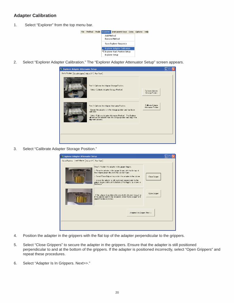
Adapter Calibration
1. Select “Explorer” from the top menu bar.
2. Select “Explorer Adapter Calibration.” The “Explorer Adapter Attenuator Setup” screen appears.
3. Select “Calibrate Adapter Storage Position.”
4. Position the adapter in the grippers with the fl at top of the adapter perpendicular to the grippers.
5. Select “Close Grippers” to secure the adapter in the grippers. Ensure that the adapter is still positioned perpendicular to and at the bottom of the grippers. If the adapter is positioned incorrectly, select “Open Grippers” and repeat these procedures.
6. Select “Adapter Is In Grippers. Next>>.”

21
7. Select “Yes.” Note: If the adapter needs to be repositioned in the grippers, select “No.” A screen will appear instructing the user to reposition the adapter correctly by opening the grippers if necessary.
8. Select “Z Axis Hover.” The Z axis will position the attenuator slightly above the adapter storage position. If necessary, use the right/left and forward/backward arrows to reposition the Z axis so that the adapter is centered above the storage position. The “High” arrows move the arm 10,000 counts. The “Med” arrows move the arm 1,000 counts. The “Low” arrows move the arm 100 counts.
Note: In the “Z Axis Hover” position, the lip of the adapter should be approximately 2mm above the storage position as illustrated below. If adjustment is not required, proceed to step 11.
9. If the “Z Axis Hover” position requires adjustment, select “Adjust Hover/Inside Z Height” in the lower left corner of the screen.
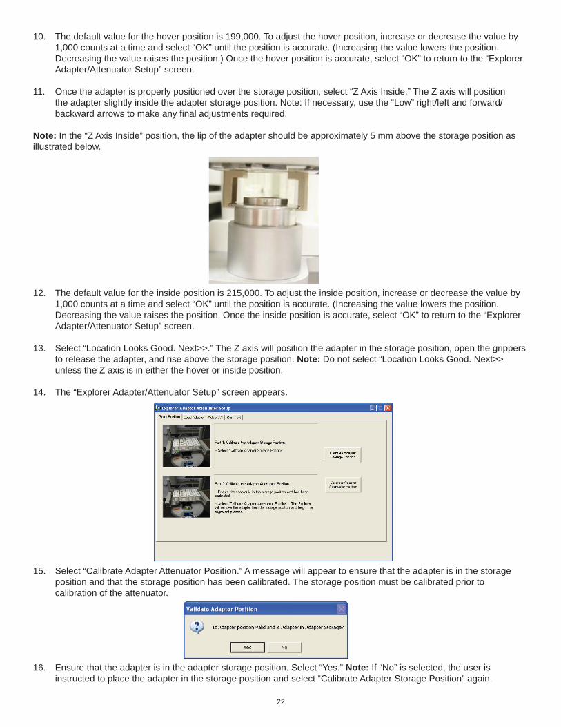
22
10. The default value for the hover position is 199,000. To adjust the hover position, increase or decrease the value by 1,000 counts at a time and select “OK” until the position is accurate. (Increasing the value lowers the position. Decreasing the value raises the position.) Once the hover position is accurate, select “OK” to return to the “Explorer Adapter/Attenuator Setup” screen.
11. Once the adapter is properly positioned over the storage position, select “Z Axis Inside.” The Z axis will position the adapter slightly inside the adapter storage position. Note: If necessary, use the “Low” right/left and forward/ backward arrows to make any fi nal adjustments required.
Note: In the “Z Axis Inside” position, the lip of the adapter should be approximately 5 mm above the storage position as illustrated below.
12. The default value for the inside position is 215,000. To adjust the inside position, increase or decrease the value by 1,000 counts at a time and select “OK” until the position is accurate. (Increasing the value lowers the position. Decreasing the value raises the position. Once the inside position is accurate, select “OK” to return to the “Explorer Adapter/Attenuator Setup” screen.
13. Select “Location Looks Good. Next>>.” The Z axis will position the adapter in the storage position, open the grippers to release the adapter, and rise above the storage position. Note: Do not select “Location Looks Good. Next>> unless the Z axis is in either the hover or inside position.
14. The “Explorer Adapter/Attenuator Setup” screen appears.
15. Select “Calibrate Adapter Attenuator Position.” A message will appear to ensure that the adapter is in the storage position and that the storage position has been calibrated. The storage position must be calibrated prior to calibration of the attenuator.
16. Ensure that the adapter is in the adapter storage position. Select “Yes.” Note: If “No” is selected, the user is instructed to place the adapter in the storage position and select “Calibrate Adapter Storage Position” again.

23
18. Select “Z Axis Hover.” The Z axis will position the adapter slightly above the attenuator. If necessary, use the right/ left and forward/backward arrows to reposition the Z axis so that the adapter is centered above the attenuator. The “High” arrows move the arm approximately 10,000 counts. The “Med” arrows move the arm approximately 1,000 counts. The “Low” arrows move the arm approximately 100 counts.
Note: In the “Z Axis Hover” position, the lip of the adapter should be approximately 2 mm above the attenuator. If the height of the hover position requires adjustment, follow the instructions above for adjusting the height for the storage posi-tion.
19. Once the adapter is properly positioned over the attenuator, select “Z Axis Inside.” The Z axis will position the adapter slightly inside the attenuator. Note: If necessary, use the “Low” right/left and forward/backward arrows to make any fi nal adjustments required.
Note: In the “Z Axis Inside” position, the lip of the adapter should be approximately 5 mm above the attenuator. If the height of the hover position requires adjustment, follow the previous instructions for adjusting the height for the storage position.
20. Select “Location Looks Good. Next>>.” The Z axis will position the adapter in the attenuator, open the grippers to release the adapter, and rise above the attenuator. Note: Do not select “Location Looks Good. Next >>” is the Z axis is in the “up” position. Lower the Z axis to either the hover or inside position prior to selecting “Location Looks Good. Next>>.”
17. Once “Yes” is selected, the Z axis retrieves the adapter from the storage position and positions itself above the attenuator.
21. To verify alignment of the adapter storage and attenuator positions, select “Return Adapter.” The Z axis will retrieve the adapter from the attenuator and place it in the storage position.
22. Select “Load Adapter.” The Z axis will retrieve the adapter from the storage position and place it in the attenuator.
24
Note: If either alignment requires adjustment, select “Alignment Requires Adjustment.” The “Explorer Adapter/Attenuator Setup” screen will appear. Follow the previous procedures to correct any adjustment required.
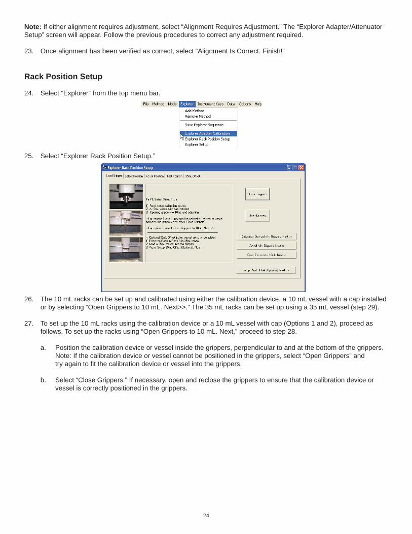
23. Once alignment has been verifi ed as correct, select “Alignment Is Correct. Finish!”
Rack Position Setup
24. Select “Explorer” from the top menu bar.
25. Select “Explorer Rack Position Setup.”
26. The 10 mL racks can be set up and calibrated using either the calibration device, a 10 mL vessel with a cap installed or by selecting “Open Grippers to 10 mL. Next>>.” The 35 mL racks can be set up using a 35 mL vessel (step 29).
27. To set up the 10 mL racks using the calibration device or a 10 mL vessel with cap (Options 1 and 2), proceed as follows. To set up the racks using “Open Grippers to 10 mL. Next,” proceed to step 28.
a. Position the calibration device or vessel inside the grippers, perpendicular to and at the bottom of the grippers. Note: If the calibration device or vessel cannot be positioned in the grippers, select “Open Grippers” and try again to fi t the calibration device or vessel into the grippers.
b. Select “Close Grippers.” If necessary, open and reclose the grippers to ensure that the calibration device or vessel is correctly positioned in the grippers.
25
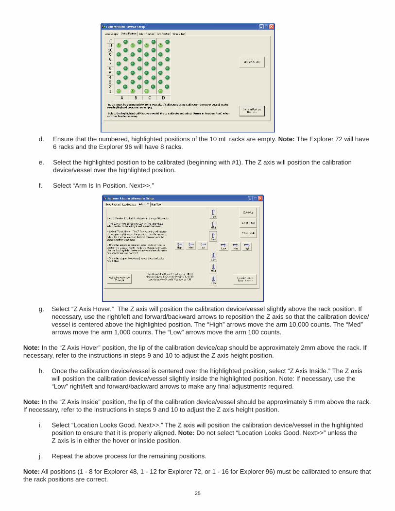
d. Ensure that the numbered, highlighted positions of the 10 mL racks are empty. Note: The Explorer 72 will have 6 racks and the Explorer 96 will have 8 racks.
e. Select the highlighted position to be calibrated (beginning with #1). The Z axis will position the calibration device/vessel over the highlighted position.
f. Select “Arm Is In Position. Next>>.”
g. Select “Z Axis Hover.” The Z axis will position the calibration device/vessel slightly above the rack position. If necessary, use the right/left and forward/backward arrows to reposition the Z axis so that the calibration device/ vessel is centered above the highlighted position. The “High” arrows move the arm 10,000 counts. The “Med” arrows move the arm 1,000 counts. The “Low” arrows move the arm 100 counts.
Note: In the “Z Axis Hover” position, the lip of the calibration device/cap should be approximately 2mm above the rack. If necessary, refer to the instructions in steps 9 and 10 to adjust the Z axis height position.
h. Once the calibration device/vessel is centered over the highlighted position, select “Z Axis Inside.” The Z axis will position the calibration device/vessel slightly inside the highlighted position. Note: If necessary, use the “Low” right/left and forward/backward arrows to make any fi nal adjustments required.
Note: In the “Z Axis Inside” position, the lip of the calibration device/vessel should be approximately 5 mm above the rack. If necessary, refer to the instructions in steps 9 and 10 to adjust the Z axis height position.
i. Select “Location Looks Good. Next>>.” The Z axis will position the calibration device/vessel in the highlighted position to ensure that it is properly aligned. Note: Do not select “Location Looks Good. Next>>” unless the Z axis is in either the hover or inside position.
j. Repeat the above process for the remaining positions.
Note: All positions (1 - 8 for Explorer 48, 1 - 12 for Explorer 72, or 1 - 16 for Explorer 96) must be calibrated to ensure that the rack positions are correct.

26
28. To set up the 10 mL racks using “Open Grippers to 10 mL. Next,” proceed as follows:
a. Select “Open Grippers to 10 mL. Next>>.” The grippers open to the position for gripping a 10 mL vessel.
b. Select the highlighted position to be calibrated (beginning with #1). The Z axis will position the grippers at the selected position.
c. Select “Arm Is In Position. Next>>.”
d. If necessary, use the right/left and forward/backward arrows to reposition the Z axis so that the grippers are centered at the highlighted position. The “High” arrows move the arm 10,000 counts. The “Med” arrows move the arm 1,000 counts. The “Low” arrows move the arm 100 counts.
e. The height can be adjusted using the Z Axis height adjustment in the top right corner.
f. Once the grippers are centered at the highlighted position, select “Location Looks Good. Next>>.” The Z axis will lift above the position.

27
g. Install the 10 mL adapter in the instrument cavity. Select a rack position. Select “Load Vessel.” The instrument will retrieve the 10 mL vessel from the selected position and place it in the attenuator.
h. Select “Return Vessel.” The instrument will retrieve the vessel from the attenuator and position it in the selected rack position.
i. Using the instructions in steps f and g, test several positions in the racks to further ensure the rack position calibration. If any adjustment is necessary, use the tabs at the top of the window to return to the “Load Gripper” screen and follow step 27 or 28 to recalibrate the position.
35 mL Vessel Offset Calibration
29. Select the “35 mL Offset” tab at the top of the screen to calibrate the rack positions for 35 mL vessels.
Note: All positions must be calibrated to ensure that the rack positions are correct. Once the fi nal position is calibrated, the following screen will appear.
30. Place an empty rack with the 35 mL positions on top in rack position A. Select “OK.”
CAUTION
The 10 mL rack calibration must be completed prior to beginning the 35 mL calibration.

28
34. Ensure that position #1 in rack A is open.
35. Press “OK” to position the vessel over position #1 of rack A.
31. Position a 35 mL vessel with a cap in the grippers perpendicular to and at the bottom of the grippers. Note: If the vessel will not fi t between the grippers, select “Open Grippers” and attempt again to place the vessel in the grippers.
32. Select “Close Grippers.” If necessary, open and close the grippers to ensure that the vessel is properly positioned in the grippers.
33. Select “35 mL Offset (Optional). Next>>.”
36. Select “Z Axis Hover.” The Z axis will position the 35 mL vessel slightly above the #1 position. If necessary, use the right/left and forward/backward arrows to reposition the Z axis so that the vessel is centered above the rack position. The “High” arrows move the arm 5,000 counts. The “Med” arrows move the arm 1,000 counts. The “Low” arrows move the arm 100 counts.
37. Once the vessel is centered over the #1 rack position, use “Z Axis Inside” to insedrt the 35 mL vessel into the rack.
38. Select “Location Looks Good.” The Z axis will position the vessel in the highlighted #1 rack position to ensure that the 35 mL rack is properly aligned. The Z axis will then raise above the vessel.

29
Note: If desired, test other vessel positions as outlined above.
39. Select “Rack Position Setup Complete.” The main Synergy screen will appear.

30
Create Method
1. The Explorer software permits three (3) options for creating a new method.
a. Select “Method” from the menu bar at the top of the screen. From the method menu, select “New Method.” b. Select the “New” button. c. From the user fi le tree, right click “Methods.” Select “New Method” from the menu.
31
2. On the left side of the “Create New Method” screen, select the method type - Standard, Dynamic, Fixed Power, Power Cycling or SPS. These options permit the user to control how the system applies the microwave energy to the reaction. In all control options, the user inputs control parameters to create the method. Note: Standard Control is the recommended control technique for routine operation. Standard Control The Standard Control is a fast and simple reaction method. The user programs 1. a temperature control point and
2. a run time (time held at the specifi ed temperature). All other method parameters are controlled by the instrument defaults. All method parameters can be edited with the “hot keys.” Dynamic Control The Dynamic Control option provides more fl exibility in how the user programs a reaction method and makes greater use of the feedback control data from the temperature and pressure systems. It applies a specifi ed amount of power, defi ned by the user, to reach the control point. It modulates this set power automatically, based on the sensor feedback data, to ensure the control point is reached rapidly, but with limited error (temperature or pressure “overshooting”). The user programs
1. the maximum amount of microwave power that can be applied to the method, 2. a temperature control point, 3. a pressure control point, 4. a hold time (the time the system maintains the control parameters), 5. a stirring function with speed control and a pre-stir option, and 6. PowerMAX (simultaneous cooling).
The Dynamic Control option can be programmed for fi ve (5) stages for multiple irradiation steps and is a general control method for maintaining critical control points. Note: Ramp time can also be programmed in a dynamic method if selected in the user’s preferences.
Power Cycling Control The Power Cycling Control option is the control with which the user can irradiate at a defi ned power to bring the reaction to the maximum temperature, then cool the sample until the minimum temperature is reached. This cycle is repeated for a user-defi ned number of times. The user programs 1. the maximum amount of microwave power applied, 2. the maximum temperature (power interval), 3. the minimum temperature (cooling interval) 4. the maximum amount of time allowed to reach the maximum and minimum temperature, and 5. the number of cycles.
Fixed Power Control The Fixed Power Control option allows the user to apply the desired power from the beginning of the reaction without a ramping time. It provides the user the most direct method to energize reaction systems. This option applies a specifi ed amount of energy for a specifi ed amount of time. Maximum temperature and pressure limits alter instrument operation, either by ending the irradiation cycle or by adjusting the power, if either is reached. The user programs
1. the amount of constant microwave power applied, 2. a maximum run time (the total time the system applies microwave energy), 3. a maximum temperature (a temperature above which the system will not apply microwave energy), and 4. PowerMAX.
The Fixed Power Control option can be programmed in two options - Control and Safe. • Control Fixed Power applies programmed power until the temperature setpoint is reached, then switches to a feedback loop which modulates the amount of power applied to maintain the setpoint temperature. • Safe Fixed Power applies programmed power until the end of the programmed reaction time or until the temperature setpoint is reached.
SPS Control The SPS Control option is the control type for the solid phase peptide systhesis applications which will irradiate at the defi ned power to bring the reaction mixture to the control temperature, then cycles the power on and off for the remainder of the run time as the temperature varies between the control temperature and a user defi ned deviation - usually 5 °C below the control temperature. The user programs
1. the input power level, 2. a control temperature (the temperature at which the magnetron will turn off), 3. a run time (the maximum run time for a stage of the method), and 4. a delta temperature (the maximum that the temperature can fall below the control temperature before the micro waves turn on).
32
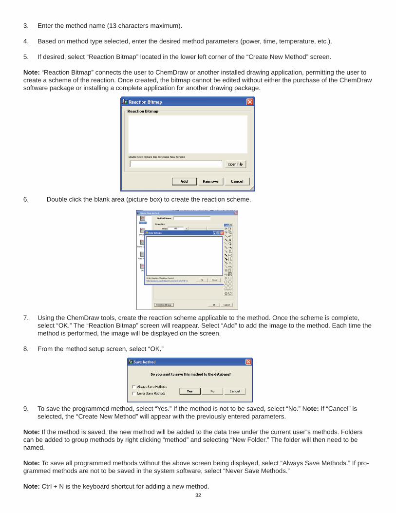
6. Double click the blank area (picture box) to create the reaction scheme.
3. Enter the method name (13 characters maximum).
4. Based on method type selected, enter the desired method parameters (power, time, temperature, etc.).
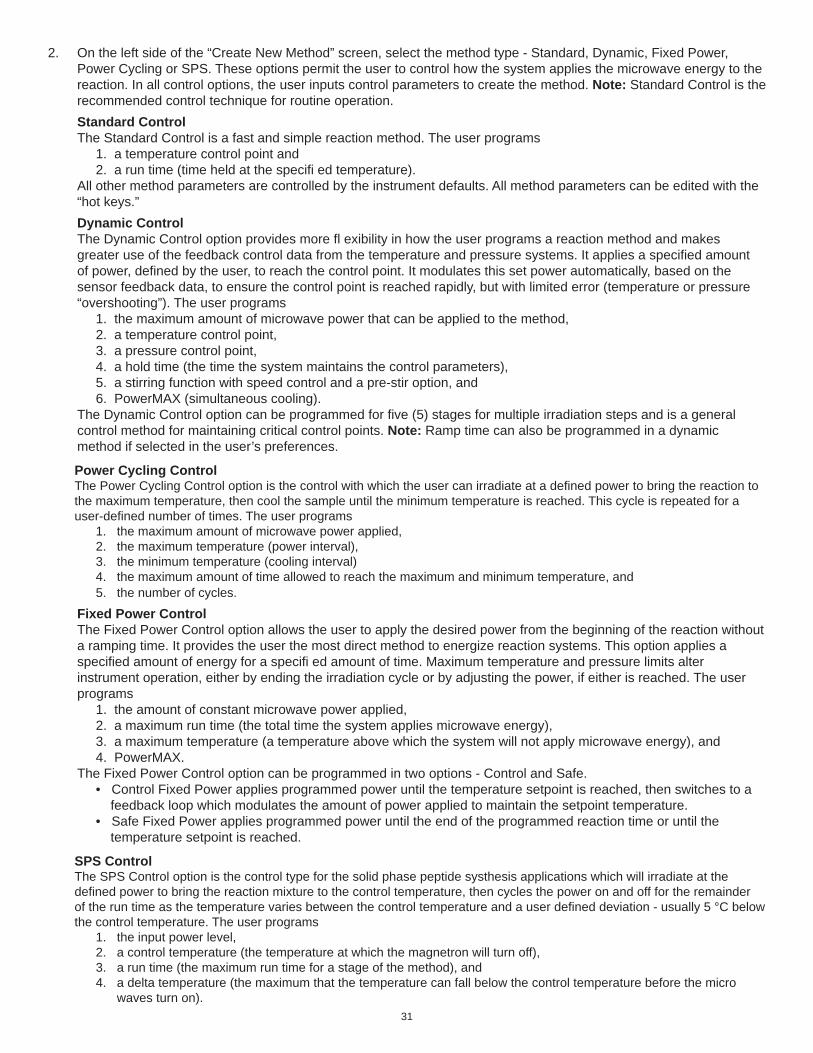
5. If desired, select “Reaction Bitmap” located in the lower left corner of the “Create New Method” screen.
Note: “Reaction Bitmap” connects the user to ChemDraw or another installed drawing application, permitting the user to create a scheme of the reaction. Once created, the bitmap cannot be edited without either the purchase of the ChemDraw software package or installing a complete application for another drawing package.
7. Using the ChemDraw tools, create the reaction scheme applicable to the method. Once the scheme is complete, select “OK.” The “Reaction Bitmap” screen will reappear. Select “Add” to add the image to the method. Each time the method is performed, the image will be displayed on the screen.
8. From the method setup screen, select “OK.”
9. To save the programmed method, select “Yes.” If the method is not to be saved, select “No.” Note: If “Cancel” is selected, the “Create New Method” will appear with the previously entered parameters.
Note: If the method is saved, the new method will be added to the data tree under the current user”s methods. Folders can be added to group methods by right clicking “method” and selecting “New Folder.” The folder will then need to be named.
Note: To save all programmed methods without the above screen being displayed, select “Always Save Methods.” If pro-grammed methods are not to be saved in the system software, select “Never Save Methods.”
Note: Ctrl + N is the keyboard shortcut for adding a new method.
33
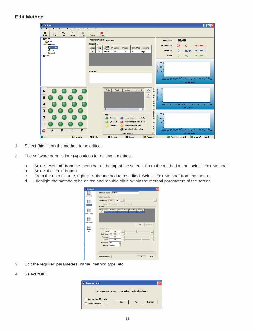
Edit Method
1. Select (highlight) the method to be edited.
2. The software permits four (4) options for editing a method.
a. Select “Method” from the menu bar at the top of the screen. From the method menu, select “Edit Method.” b. Select the “Edit” button. c. From the user fi le tree, right click the method to be edited. Select “Edit Method” from the menu. d. Highlight the method to be edited and “double click” within the method parameters of the screen.
3. Edit the required parameters, name, method type, etc.
4. Select “OK.”

34
5. To save the edited method, select “Yes.” If the method is not to be saved, select “No.”
Note: If the method name is edited, the original method name and parameters as well as the new method and parameters will be saved.
NOTE: To save all programmed methods without the above screen being displayed, select “Always Save Methods.” If programmed methods are not be be saved in the system software, select “Never Save Methods.”
Note: Ctrl + E is the keyboard shortcut for editing a method.

35
Delete Method
CAUTION
Deleting a method will permanently erase the information from the instrument software.
1. Select (highlight) the method to be deleted.
2. The software permits three (3) options for deleting a method.
a. Select “Method” from the menu bar at the top of the screen. From the method menu, select “Delete Method.” b. Select the “Delete” button. c. From the user fi le tree, right click the method to be deleted. Select “Delete Method” from the menu.
1. Select “OK.” The method will be permanently deleted from the user fi le tree.
Note: Deleting a method will not effect previously performed methods by that name nor their data.
Note: Ctrl + K is the keyboard shortcut for deleting a method.
36
Add Method to Explorer Rack
Note: A method must be created and stored in the Synergy software memory to add a method to the Explorer rack. A method cannot be added to a cell if the cell has previously been highlighted.
1. Select (highlight) the method to be added to the rack(s).
2. The software permits four (4) methods for adding a single method.
a. “Double click” the desired rack position for the method.
b. “Right click” the desired rack position for the method, and select “Add Method.”
c. “Left click” the method to be added, and while holding the mouse button, drag and drop the method into the desired rack position for the method.
d. Highlight the desired rack position for the method. Select “Explorer” from the top menu. Select “Add Method.”
3. Two (2) methods are available for multiple additions of a single method to the rack(s).
a. “Right click” a rack header letter or number to select an entire or column of a rack. “Right click” any of the highlighted positions and select “Add Method.”
b. While pressing the “Shift” key on the keyboard, select the fi rst position in which to add the method, then select the fi nal position (vertically) in which to add the method. The method will be added to all positions between the fi rst and fi nal selected positions. Depressing the “Control” key permits non-sequential cells to be selected in the same manner.
Remove Method(s) from Explorer Rack
1. Two (2) methods are available for removing a method from the rack(s).
a. Highlight the rack position from which the method is to be removed. Select “Explorer” from the top menu. Select “Remove Method.”
b. “Right click” the rack position from which the method is to be removed. Select “Remove Method.”
2. To remove all methods from the Explorer racks, “right click” any rack position and select “Clear Explorer Racks.” A screen will appear asking “Are you sure you with to clear explorer racks. Yes or No.” Select “Yes” to clear the methods from all rack positions. If “No” is selected, the methods in the rack positions will remain as selected.
Save Explorer (Method) Sequence
1. The ability to save an Explorer (method) sequence permits the user to create a series of methods in the Explorer rack(s) and save the series by an assigned name so that it can be recalled for ease and speed of programming. Follow the procedures outlined below to save a method sequence:
a. Add the method(s) to the Explorer racks as outlined above. If necessary, use the “up” and “down” arrows beside the “rack status” section of the Explorer screen to edit the order of the methods to be performed.
b. Once the methods and the order of performance are determined, select “Explorer” from the top menu. Select “Save Explorer Sequence.”
c. When the screen appears requesting a sequence name, using the keyboard, enter the desired name for the sequence. Select “OK” to save the sequence or “Cancel” to cancel the save.
2. To perform a saved sequence, vessel sizes must be the same as those used when setting up the sequence. If all 10 mL vessels were used to set up the sequence, all 10 mL vessels must be used to perform the sequence again. If the racks were set up as 10 mL, 35 mL, 35 mL, 10 mL, they must be set up in that manner to reuse the sequence.
37
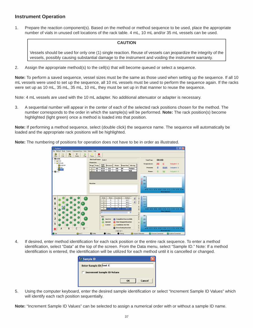
Instrument Operation
1. Prepare the reaction component(s). Based on the method or method sequence to be used, place the appropriate number of vials in unused cell locations of the rack table. 4 mL, 10 mL and/or 35 mL vessels can be used.
CAUTION
Vessels should be used for only one (1) single reaction. Reuse of vessels can jeopardize the integrity of the vessels, possibly causing substantial damage to the instrument and voiding the instrument warranty.
2. Assign the appropriate method(s) to the cell(s) that will become queued or select a sequence.
Note: To perform a saved sequence, vessel sizes must be the same as those used when setting up the sequence. If all 10 mL vessels were used to set up the sequence, all 10 mL vessels must be used to perform the sequence again. If the racks were set up as 10 mL, 35 mL, 35 mL, 10 mL, they must be set up in that manner to reuse the sequence.
Note: 4 mL vessels are used with the 10 mL adapter. No additional attenuator or adapter is necessary.
3. A sequential number will appear in the center of each of the selected rack positions chosen for the method. The number corresponds to the order in which the sample(s) will be performed. Note: The rack position(s) become highlighted (light green) once a method is loaded into that position.
Note: If performing a method sequence, select (double click) the sequence name. The sequence will automatically be loaded and the appropriate rack positions will be highlighted.
Note: The numbering of positions for operation does not have to be in order as illustrated.
4. If desired, enter method identifi cation for each rack position or the entire rack sequence. To enter a method identifi cation, select “Data” at the top of the screen. From the Data menu, select “Sample ID.” Note: If a method identifi cation is entered, the identifi cation will be utilized for each method until it is cancelled or changed.
5. Using the computer keyboard, enter the desired sample identifi cation or select “Increment Sample ID Values” which will identify each rach position sequentially.
Note: “Increment Sample ID Values” can be selected to assign a numerical order with or without a sample ID name.

38
Note: Once a method has been loaded into rack positions, the system operator can “right click” one of the highlighted positions to perform several functions.
Add Method - Add method replaces the queued method with the highlighted method. Remove Method - Removes the queued method. Edit Method for This Cell - Permits editing of method parameters for the selected cell only. Sample ID for This Cell - Permits entering of a sample ID for the selected cell only. Run At Date/Time - Permits selection of a date and time to perform the queued method. Clear Explorer Racks - Clears all methods from all racks.
6. To program the date/time for queued method(s) to begin, select the date and time to begin the fi rst selected rack position. Ensure the “active” window is selected to activate the selection.

39
7. From the top of the Explorer menu, select “Play.” Note: The active rack position becomes yellow. The instrument automatically adjusts for use of 10 mL or 35 mL vessels, retrieves the vessel from the active rack position and positions it in the attenuator. The APD positions itself over the vessel and locks into position. The method proceeds through the programmed parameters.
8. During the performance of a method, the status window of the screen displaying the current method conditions can be “double clicked” to enlarge it to proportions that can be viewed from a distance.
Note: The above screen can be programmed in the user’s preferences to automatically appear at the beginning of each reaction.
9. Instrument operation can be paused by selecting the “Pause” button or selecting “Instrument Keys,” then selecting “Pause” from the menu. The method will be paused and can be resumed by selecting the “Play” button or selecting “Instrument Keys,” then selecting “Play” from the menu or by selecting Ctrl + S.
10. To stop a reaction prior to completion, select (left mouse click) the “Stop” button or select “Instrument Keys,” then select “Stop ” or select Ctrl + 0. The reaction is stopped and cannot be resumed. Once the method is stopped, cooling begins prior to release of the vessel. Once the vessel is cooled suffi ciently, the automatic pressure device unlocks the attenuator and moves into the idle position. The instrument then removes the vessel from the attentuator and places it into the proper rack position. The rack position of the rack table becomes red, indicating that the user stopped the reaction.

40
11. During the method operation, the following instrument “hot keys” can be used to edit method parameters. The “hot keys” can be utilized from either the Discover module keypad or from the Synergy software on the computer.
Temperature
Pressure
Time
Power
Cooling
Stirring
Enter
Arrow Arrow+
-
Power - 0 - 300W range Synergy - Select the Power key. From the Power screen, either use the computer keyboard to enter the desired power or use the sliding scale to select desired power. Discover Keypad - Press the Power key. Use the “+/-” keys to increase or decrease power. Press “Enter.”
Stirring - Low, Medium, High or Off Synergy - From the Stirring screen, select the desired stirring speed. Discover Keypad - Press the Stirring key. Use the “+/-” keys to toggle the stirring speed. Press “Enter.”
Cooling - Select the “Cooling - PowerMax” key to toggle between “on” and “off.”
Temperature - 0 °C - 300 °C Synergy - Select the Temperature key. For Standard, Dynamic, Fixed Power and SPS methods, either use the computer keyboard to enter the desired temperature or use the sliding scale to select the desired temperature. For a fi xed power method, also select “safe” or “control” For an SPS method, also enter or select the delta temperature (maximimum number of degrees that the temperature can fall below the control temperature before microwaves turn on). For Power Cycling methods, either enter or select both a minimum and a maximum temperature. Discover Keypad - For Standard, Dynamic, Fixed Power and SPS methods, press the temperature key, then use the “+/-” keys to increase or decrease temperature. Press “Enter.” For a fi xed power method, also press the right arrow and “+/-” keys to toggle and select “safe” or “control.” For an SPS method, also use the “+/-” keys to enter the delta temperature (maximum number of degrees that the temperature can fall below the control temperature before microwaves turn on). For Power Cycling methods, also use the “+/-” keys to increase or decrease both a minimum and maximum temperature.
Pressure - 0 - 300 PSI or 0 - 21 BAR Synergy - Select the Pressure key. Form the Pressure screen, either use the computer keyboard to enter the desired power or use the sliding scale to select the desired pressure. Discover Keypad - Press the Pressure key. Use the “+/-” keys to increase or decrease the pressure. Press “Enter.”
Time - 1 Second to 99 Hours, 59 Minutes and 59 Seconds Synergy - Select the Time key. For Standard, Dynamic, Fixed Power and SPS methods, use the computer keyboard to enter the desired time. For Power Cycling methods, use the computer keyboard to enter the power interval and the cooling interval times. Discover Keypad - Press the Time key. Use the “+/-” keys to increase or decrease the time. For Power Cycling methods, increase or decrease the power interval and the cooling interval times.

41
Note: If an instrument error occurs during performance of the reaction, the reaction will stop, the vessel will be cooled and returned to its rack position. The rack position on the rack table will become black, indicating that an error occurred during the reaction or a missing vessel.
12. Once the method is complete, the cooling cycle will begin. Once cooling is complete, the vessel will be returned from the attenuator to its proper rack position. The following screen will appear.
Note: The completed rack position(s) will become blue, indicating that the reaction was completed successfully. The instrument will continue to perform each reaction loaded into the rack positions.
CAUTION
Vessels should be used for only one (1) single reaction. Reuse of vessels can jeopardize the integrity of the vessels, possibly causing substantial damage to the instrument and voiding the instrument warranty.
Note: If the active rack position becomes red, the method has been stopped. If the rack position becomes orange, the parameters are not met. If the rack position becomes black, an operation error occurred during the reaction.
Note: If methods are programmed into more than one rack position, the instrument will continue operation until allselected rack positions have been completed. If rack positions are programmed for both 10 mL and 35 mL vessels, the instrument will automatically place the adapter in the attenuator or remove it from the attenuator to accommodate either size vessel.
42
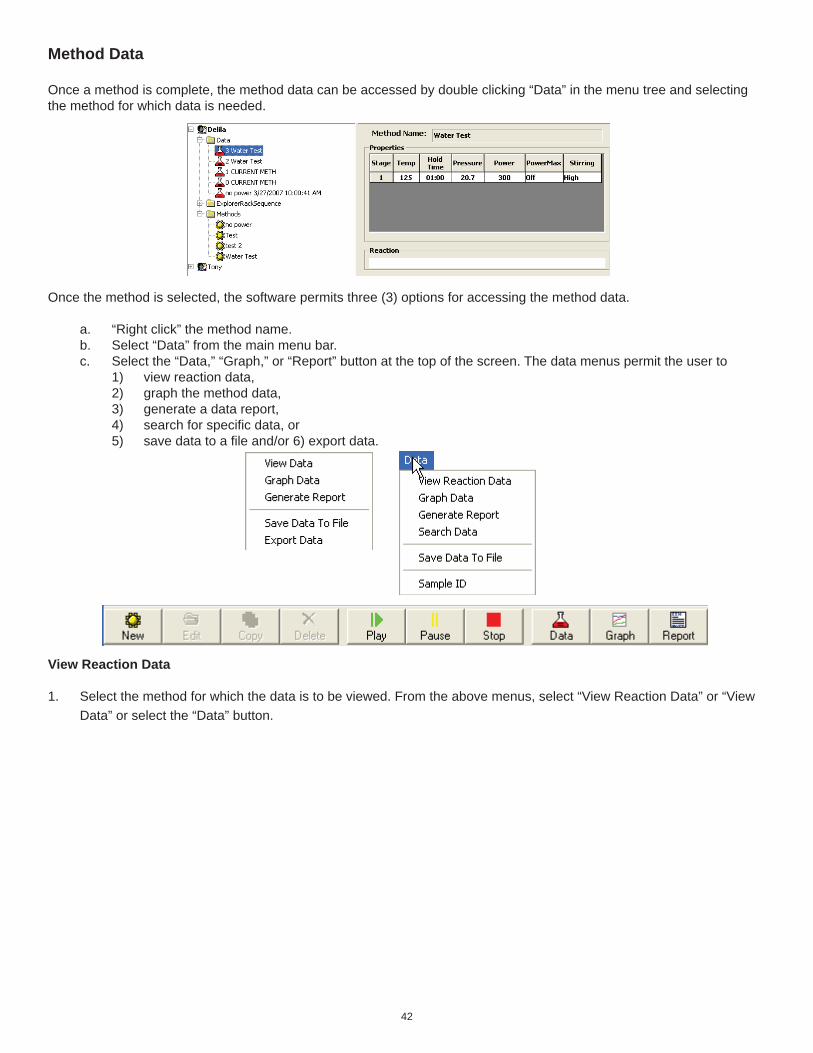
Method Data
Once a method is complete, the method data can be accessed by double clicking “Data” in the menu tree and selecting the method for which data is needed.
Once the method is selected, the software permits three (3) options for accessing the method data.
a. “Right click” the method name. b. Select “Data” from the main menu bar. c. Select the “Data,” “Graph,” or “Report” button at the top of the screen. The data menus permit the user to 1) view reaction data, 2) graph the method data, 3) generate a data report, 4) search for specifi c data, or 5) save data to a fi le and/or 6) export data.
View Reaction Data
1. Select the method for which the data is to be viewed. From the above menus, select “View Reaction Data” or “View Data” or select the “Data” button.

43
The “method” window of the “Data Properties” screen provides the selected method information including the method parameters.
The “Reaction Notes” window details information pertaining to the particular reaction such as time at temperature, at what point the setpoint was achieved, the maximum temperature, the maximum pressure, etc.
The “Reaction Image” window is the reaction scheme associated with the method. The reaction scheme can be added to the data fi le by “double clicking” on the blank space of the reaction window. Note: Schemes that have been saved previously can be imported by using the “Open File” button and browsing for the saved fi le.
The “Reaction Graph” window displays graphs from the reaction.
The “Experimental Notes” window permits user editable notes associated with the reaction.
A report can be generated directly from the above screen by selecting the “Generate Report” button at the bottom of the screen.
2. Make any changes necessary. Only the title, reaction notes and reaction image may be edited.
3. If desired, select “OK” to save changes. Note: Changes, if saved, will appear in any future data reports.

44
Graph Data
The data graphs magnify the temperature, pressure and power from the selected method.
1. “Right click” the graph to access the graph menu which permits the user to select 1 or 3 graphs, save the graph to a new fi le or change the X/Y axis properties. Note: The instrument default for the graph screen is 3 graphs (temperature, pressure and power). If one graph is selected, the graph will display all three parameters.
2. Select “Save Graph” to save the graph to a new csv fi le. A screen will appear permitting the user to select a fi le name and location within the computer fi les.
3. Select “Change Y Axis” to change the Y axis of the graph. A screen will appear permitting the user to enter a Y Axis Minimum and Y Axis Maximum.
4. “Double Click” one of the individual graphs from the 3-graph screen. The selected graph will appear with the following graph tools: Axes Scroll - change the X/Y axis. Axes Zoom - with the “Axes Zoom” key depressed, move the mouse to zoom the axis in or out. Zoom Out - select “Zoom Out” and axis will be zoomed out. Zoom In - select “Zoom In” and axis will be zoomed in. Select - with the “Select” button selected, “left click” within the graph, depress the mouse button and move the cursor to position the axis. Zoom Box - with the “Zoom Box” button selected, “left click” within the graph, depress the mouse button and move the cursor to create a box around a desired area. Release the mouse button, and the boxed area becomes the max/min parameters. Data Cursor - select the “Data Cursor” button. A red cross appears on the graph. Click the center of the cross and depress the mouse button. Move the mouse to view various data points. Depress the “Data Cursor” button to dismiss the red cross from the graph. Change Y Axis - select the “Change Y Axis” button to edit the Y Axis Minimum and Y Axis Maximum. Save Graph - select the “Save Graph” button to save the graph using a new name.
5. Select “Close,” press “ESC” on the computer keyboard, or press the “X” in the top right corner of the screen to exit the graph tools screen.
45
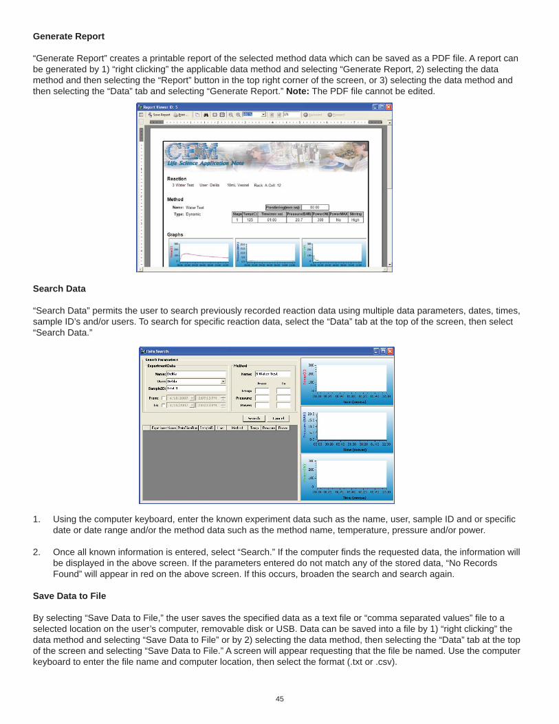
Generate Report
“Generate Report” creates a printable report of the selected method data which can be saved as a PDF fi le. A report canbe generated by 1) “right clicking” the applicable data method and selecting “Generate Report, 2) selecting the data method and then selecting the “Report” button in the top right corner of the screen, or 3) selecting the data method and then selecting the “Data” tab and selecting “Generate Report.” Note: The PDF fi le cannot be edited.
Search Data
“Search Data” permits the user to search previously recorded reaction data using multiple data parameters, dates, times, sample ID’s and/or users. To search for specifi c reaction data, select the “Data” tab at the top of the screen, then select “Search Data.”
1. Using the computer keyboard, enter the known experiment data such as the name, user, sample ID and or specifi c date or date range and/or the method data such as the method name, temperature, pressure and/or power.
2. Once all known information is entered, select “Search.” If the computer fi nds the requested data, the information will be displayed in the above screen. If the parameters entered do not match any of the stored data, “No Records Found” will appear in red on the above screen. If this occurs, broaden the search and search again.
Save Data to File
By selecting “Save Data to File,” the user saves the specifi ed data as a text fi le or “comma separated values” fi le to a selected location on the user’s computer, removable disk or USB. Data can be saved into a fi le by 1) “right clicking” the data method and selecting “Save Data to File” or by 2) selecting the data method, then selecting the “Data” tab at the top of the screen and selecting “Save Data to File.” A screen will appear requesting that the fi le be named. Use the computer keyboard to enter the fi le name and computer location, then select the format (.txt or .csv).
46
Maintenance, Troubleshooting and ServiceThis section covers routine maintenance, troubleshooting and minor parts replacement. For service and repair, contact the CEM Service Department or local CEM subsidiary or distributor. A routine preventive maintenance program is recom-mended to ensure optimum performance of the Explorer System.
WARNING
This instrument utilizes high voltages and microwave radiation. Only technicians trained in repair and main-tenance of high voltage and microwave power systems should perform instrument service and repair.
WARNING
Proper precautions must be taken to avoid contact with solvents or solvent vapors. Protective gear should be worn as outlined in the user’s safety program for hazardous materials and the reagent manufacturer’s material safety data sheet. Refer to these guidelines for proper handling and disposal of reagents.
Routine Maintenance and Cleaning
Interlocks – Weekly, examine the cavity edge and attenuator interlocks to verify that they are clean and working properly.
Cavity – Weekly, remove the cavity liner and wipe the liner with an alcohol wipe or equivalent. Inspect the IR lens for for-eign debris and/or damage. If necessary, use a swab and alcohol to clean the IR lens. If the lens is damaged, call CEM Service.
APD – Monthly or as required, clean the automated pressure device as outlined below.
APD Cleaning
WARNING
Cardiac pacemakers require magnets to control operation during checkout. If the Discover module is equipped with a sample stirrer, some danger exists if a pacemaker is positioned in close proximity to the instrument cavity. If the instrument is suspected of interfering with the operation of a pacemaker, the instru-ment should be turned off or the pacemaker wearer should move away from the instrument.
1. Log into the instrument software as a user with Standard or Administrative privileges.
2. Select the “Home” key on the Discover module keypad.
3. Use the down arrow to select “System Setup.”
4. Press the “Enter” key.
NOTE
If the “System Setup” screen does not display, the user does not have Standard or Administrative privileges. Log into the instrument software again using a user name with Standard or Administrative privileges.
5. Press the right arrow key three (3) times to select “Peripheral Setup.”
6. Press the down arrow key two (2) timesto select “APD Cleaning.”
7. Press the “Enter” key. The following screen will appear.
APD Cleaning Remove Attenuator and install APD Cleaning Cup with stirring bar and add 275 mL of liquid solvent. Press ENTER when ready.

47
8. Remove the attenuator from the instrument cavity. Leave the spill cup inside the instrument cavity.
9. Add 275 mL of appropriate solvent and an adequate stir bar for creating a vortex into the cleaning cup.
WARNING
Proper precautions must be taken to avoid contact with solvents or solvent vapors. Protective gear should be worn as outlined in the user’s safety program for hazardous materials and the reagent manufacturer’s material safety data sheet. Refer to these guidelines for proper decontamination, handling and disposal of reagents or any hazardous materials.
NOTE
Use a low boiling point solvent (T <80 C) that will dissolve debris on the APD. Suggested solvents include methanol, ethanol, acetone and hexane.
9. Place the cleaning cup inside the instrument cavity.
10. Press the “Enter” key. The following screen will appear.
APD Cleaning Press “Enter” to edit cleaning time and then press “Start” when ready. A 5:00 minute pre-cleaning time will precede the set cleaning time. Cleaning time = 00:10 (hh:mm)
11. To edit the cleaning time, press the “Enter” key. Use the right and left arrow keys to toggle between hours and minutes. Use the “+/-” keys to increase or decrease the highlighted number.
12. Once the selected cleaning time has been selected, press the “Enter” key. The following screen will appear.
APD Cleaning Drying APD.
Note: The pre-cleaning process partially lowers the head of the APD into the cleaning solution. The cleaning process lowers the entire head of the APD into the cleaning solution. If the APD is unable to lower the head into the solution, an error will occur. If an error occurs, contact CEM Service.
Note: To stop the cleaning process, press the “Stop” key.
13. Once the APD cleaning process is complete, an automatic two-minute (2) drying process will begin. The APD will remain above the cleaning cup during this time to prevent solvent spills.
14. Once the drying process is complete, the APD will return to the “Home” position. The following screen will appear.
APD Cleaning APD Cleaning process is complete. Remove APD cleaning cup after the APD is in the Home position. Press the Home key.
WARNING
Proper precautions must be taken to avoid contact with solvents or solvent vapors. Protective gear should be worn as outlined in the user’s safety program for hazardous materials and the reagent manufacturer’s material safety data sheet. Refer to these guidelines for proper decontamination, handling and disposal of reagents or any hazardous materials.

48
14. Remove the cleaning cup. Remove the stir bar. Dispose of the solvent in accordance with the guidelines outlined in the solvent manufacturer’s Material Safety Data Sheet.
15. Remove the spill cup from the instrument cavity.
16. Ensure that the cavity and IR lens are clean and dry.
CAUTION
If liquid is present in the instrument cavity, use a swab to dry the IR lens and a dry wipe to dry the remainder of the cavity.
17. Install the spill tray in the instrument cavity.
Note: If the spill tray appears to be damaged, replace the spill tray. If a new spill tray is installed, calibrate the temperature sensor. Refer to the Discover module Operation Manual for calibration instructions.
18. Install the appropriate attenuator into the instrument cavity.
Microwave Leakage Measurement
The attenuator and cavity of the Discover module are durable and are designed for reliable operation under severe laboratory conditions. External radiation checks are performed on the Discover module at several points in the manufacturing process, ensuring that leakage from the fi nished instrument is only a fraction of that allowed by U.S. law (5 mW/cm2).
The attenuator is equipped with a safety interlock system to stop the generation of microwave energy when the attenuator is opened or ajar. If the interlock system fails, a monitoring mechanism will blow the fuse(s) through which power is supplied to the magnetron, rendering the microwave power system inoperable.
To verify that seals and interlocks are working properly, the Discover System should be tested periodically for microwave leak-age. Use the following procedure to measure microwave leakage:
1. Create a dynamic method using 300 watts of power, 1 minute run time, 95 oC temperature set-point, stirring turned on at the “high” setting and PowerMAX on.
2. Place a round bottom fl ask containing 50mL of deionized water into the cavity.3. Attach the attenuator to accept a 24/40 ground glass joint.4. Load the created method and press “Start” to begin the method.5. Use a suitable RF fi eld strength meter (microwave detector) such as the Holaday Model HI-1500 (available from CEM
Corporation, P/N 300500). Slowly move the RF probe around the attenuator perimeter and around the fan grills to check for microwave leakage.
NOTE
CEM does not recommend use of meters available in electronics stores because they are prone to give errone-ous readings and lack the necessary sensitivity to properly test an instrument for microwave leakage.
The U.S. Government defi nes excessive microwave leakage as 5 mW/cm2. If the instrument shows excessive microwave leak-age, do not attempt further operation. Contact the CEM Corporation Service Department or the local CEM subsidiary or distribu-tor for further instructions.
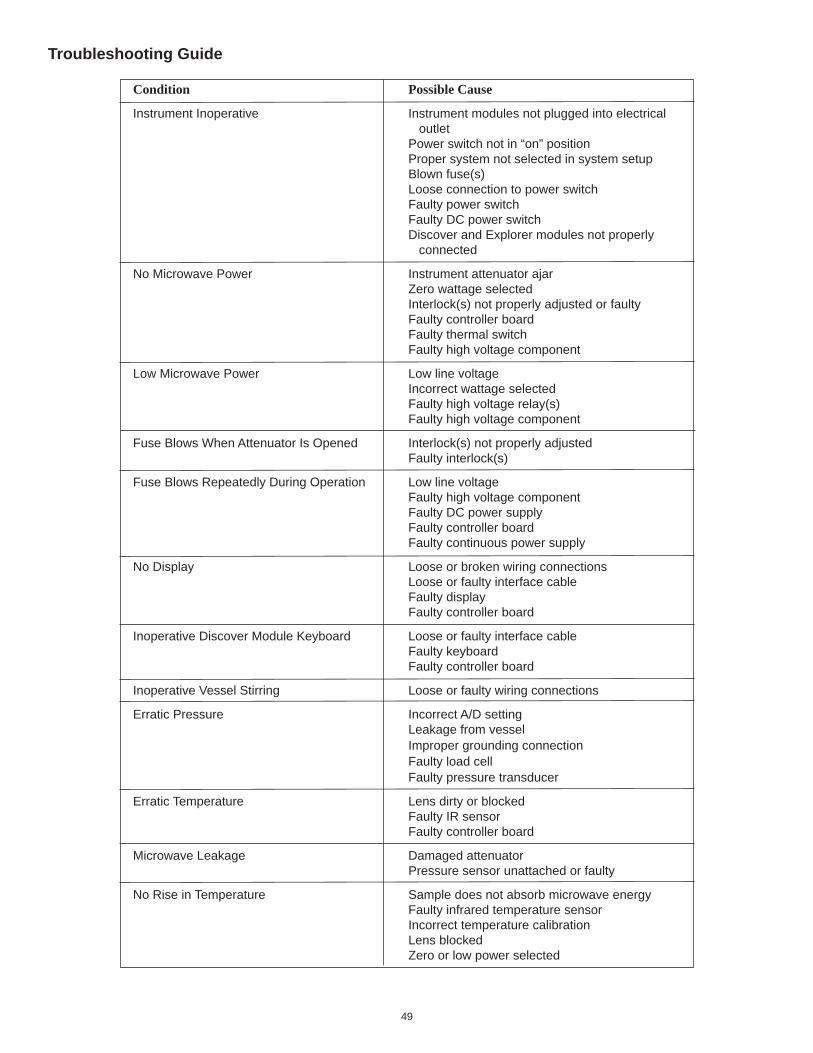
49
Condition Possible Cause
Instrument Inoperative Instrument modules not plugged into electrical outlet Power switch not in “on” position Proper system not selected in system setup Blown fuse(s) Loose connection to power switch Faulty power switch Faulty DC power switch Discover and Explorer modules not properly connected
No Microwave Power Instrument attenuator ajar Zero wattage selected Interlock(s) not properly adjusted or faulty Faulty controller board Faulty thermal switch Faulty high voltage component
Low Microwave Power Low line voltage Incorrect wattage selected Faulty high voltage relay(s) Faulty high voltage component
Fuse Blows When Attenuator Is Opened Interlock(s) not properly adjusted Faulty interlock(s)
Fuse Blows Repeatedly During Operation Low line voltage Faulty high voltage component Faulty DC power supply Faulty controller board Faulty continuous power supply
No Display Loose or broken wiring connections Loose or faulty interface cable Faulty display Faulty controller board
Inoperative Discover Module Keyboard Loose or faulty interface cable Faulty keyboard Faulty controller board
Inoperative Vessel Stirring Loose or faulty wiring connections
Erratic Pressure Incorrect A/D setting Leakage from vessel Improper grounding connection Faulty load cell Faulty pressure transducer
Erratic Temperature Lens dirty or blocked Faulty IR sensor Faulty controller board
Microwave Leakage Damaged attenuator Pressure sensor unattached or faulty
No Rise in Temperature Sample does not absorb microwave energy Faulty infrared temperature sensor Incorrect temperature calibration Lens blocked Zero or low power selected
Troubleshooting Guide
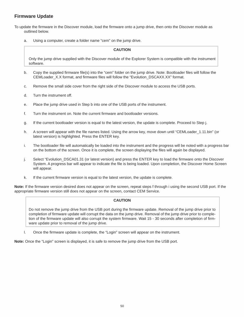
50
Firmware Update
To update the fi rmware in the Discover module, load the fi rmware onto a jump drive, then onto the Discover module as outlined below.
a. Using a computer, create a folder name “cem” on the jump drive.
CAUTION
Only the jump drive supplied with the Discover module of the Explorer System is compatible with the instrument software.
b. Copy the supplied fi rmware fi le(s) into the “cem” folder on the jump drive. Note: Bootloader fi les will follow the CEMLoader_X.X format, and fi rmware fi les will follow the “Evolution_DSCAXX.XX” format.
c. Remove the small side cover from the right side of the Discover module to access the USB ports.
d. Turn the instrument off.
e. Place the jump drive used in Step b into one of the USB ports of the instrument.
f. Turn the instrument on. Note the current fi rmware and bootloader versions.
g. If the current bootloader version is equal to the latest version, the update is complete. Proceed to Step j.
h. A screen will appear with the fi le names listed. Using the arrow key, move down until “CEMLoader_1.11.bin” (or latest version) is highlighted. Press the ENTER key.
i. The bootloader fi le will automatically be loaded into the instrument and the progress will be noted with a progress bar on the bottom of the screen. Once it is complete, the screen displaying the fi les will again be displayed.
j. Select “Evolution_DSCA01.31 (or latest version) and press the ENTER key to load the fi rmware onto the Discover System. A progress bar will appear to indicate the fi le is being loaded. Upon completion, the Discover Home Screen will appear.
k. If the current fi rmware version is equal to the latest version, the update is complete.
Note: If the fi rmware version desired does not appear on the screen, repeat steps f through i using the second USB port. If the appropriate fi rmware version still does not appear on the screen, contact CEM Service.
CAUTION
Do not remove the jump drive from the USB port during the fi rmware update. Removal of the jump drive prior to completion of fi rmware update will corrupt the data on the jump drive. Removal of the jump drive prior to comple-tion of the fi rmware update will also corrupt the system fi rmware. Wait 15 - 30 seconds after completion of fi rm-ware update prior to removal of the jump drive.
l. Once the fi rmware update is complete, the “Login” screen will appear on the instrument.
Note: Once the “Login” screen is displayed, it is safe to remove the jump drive from the USB port.

51
Computer Setup
1. With the computer properly connected to the Discover module of the Explorer 48/72/96 and plugged into an electrical outlet, turn on the computer and the instrument.
2. Log into the instrument as an “administrator.”
3. Confi rm the computer IP address as follows.
NOTE: The following instructions apply to Windows 2000. If a different operating system is used, the instructions may vary.
a. Select (right click) the “My Network Places” icon on the desktop.
b. Select “Properties” to access the “Network Connections” window.
c. Select (right click) “Local Area Connection.”
d. Select “Properties” to open the Local Area Connections Properdies window.
e. Select “General.”
f. Highlight the “Internet Protocol (TCP/IP)” connection and select “Properties” to access the Internet Protocol (TCP/IP) properties window.

52
g. Select “General.”
h. If the “Use the following IP address” box is selected and the IP address reads 192.168.1.10 and the subnet mask reads 255.255.0.0, proceed to the next step. If the IP address and subnet mask do not read as above, edit these fi elds as required. (Once the proper IP address is entered, the subnet mask will populate by pressing the “Tab” key on the computer keyboard.
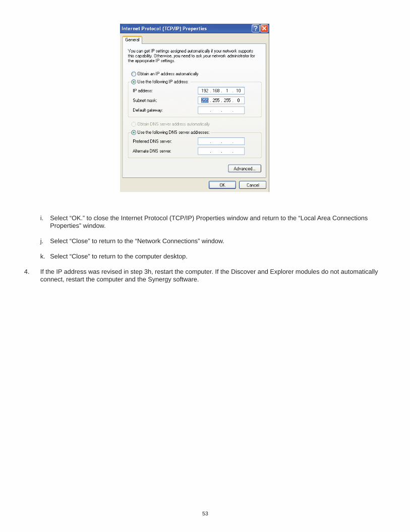
53
i. Select “OK.” to close the Internet Protocol (TCP/IP) Properties window and return to the “Local Area Connections Properties” window.
j. Select “Close” to return to the “Network Connections” window.
k. Select “Close” to return to the computer desktop.
4. If the IP address was revised in step 3h, restart the computer. If the Discover and Explorer modules do not automatically connect, restart the computer and the Synergy software.
54
Repair and Service
WARNING
This instrument utilizes high voltages and microwave radiation in its operation. Only technicians trained in repair and maintenance of high voltage and microwave power systems should undertake instrument service and repair.
WARNING
Proper precautions must be taken to avoid contact with solvents or solvent vapors. Protective gear should be worn as outlined in the user’s safety program for hazardous materials and the reagent manufacturer’s material safety data sheet. Refer to these guidelines for proper decontamination, handling and disposal of reagents or any hazardous materials.
The Explorer 48/72/96 System is constructed in modular form to facilitate troubleshooting and repair. It is recommended that troubleshooting and repair by the user be limited to identifying and replacing parts such as printed circuit boards, fans, lamps, or motors.
WARNING
Disconnect the instrument from the AC power source prior to performing any service procedure.
Prior to any troubleshooting or service procedures in the high voltage section or area, bridge the contacts of the high voltage capacitor using the metal shaft of a well-insulated screwdriver to discharge the residual voltage in the capacitor. This will prevent exposure to high voltage discharge during troubleshooting or service.
Before replacing the high voltage plate assembly after any service procedure involving the microwave generating components, visually check the magnetron, transformers, triac, and high voltage capacitor to ensure that the electrical connections are secure.
Any service to or inspection of the Explorer System that requires • removal of the power supply assembly or • replacement of components in the • interlock mechanism, • microwave generation system, or • microwave transmission systemshould be followed by a microwave leakage measurement to verify that leakage is less than 5 mW/cm2.
CAUTION
Prior to using any cleaning or decontamination method except those recommended by the equipment manufac-turer, the user should check with the manufacturer that the proposed method will not damage the equipment.
55
Vessel Failure Cleanup Procedure
WARNING
Proper precautions must be taken to avoid contact with solvents or solvent vapors. Protective gear should be worn as outlined in the user’s safety program for hazardous materials and the reagent manufacturer’s material safety data sheet. Refer to these guidelines for proper handling and disposal of reagents.
WARNING
To prevent the possibility of severe burns, ensure that insulated gloves and protective gear as outlined in the user’s safety program are worn.
1. Remove the attenuator assembly by rotating the attenuator counterclockwise.
2. Remove the spill cup.
WARNING
If the spill cup contains glass particles or shards, ensure that the glass is placed into a proper waste container.
3. Rinse the spill cup. Once all debris is rinsed from the cup, check the cup for cracks and/or damage. Wipe the cup with an alcohol wipe or equivalent.
Note: If the spill cup is damaged, replace the cup.
4. Examine the bottom of the spill cup to ensure that the IR lens cover is in position and undamaged. If the IR lens is not in position or damaged, call CEM Service. If the IR lens is dirty, use a cotton swab and alcohol to clean the lens.
Note: If the IR lens is in proper position, it will refl ect an image similar to a mirror.
6. Clean the spill tray as outlined below.
7. If the spill cup is not damaged, place the spill cup back in the instrument cavity. Ensure that the opening in the bottom of the spill tray is aligned with the opening in the bottom of the instrument cavity.
8. If the spill cup is replaced, calibrate the IR sensor as outlined in the Discover module operation manual.
Spill Tray Cleaning
WARNING
Proper precautions must be taken to avoid contact with solvents or solvent vapors. Protective gear should be worn as outlined in the user’s safety program for hazardous materials and the reagent manufacturer’s material safety data sheet. Refer to these guidelines for proper handling and disposal of reagents.
1. Position the instrument so that the back of the instrument is accessible.
2. Remove the screw securing the spill tray to the back of the instrument cover.
3. Carefully slide the spill tray out of the instrument.
4. Properly dispose of the contents of the tray.
5. Rinse the tray with an appropriate solvent.
6. Install the spill tray and secure it to the instrument with the screw.
Note: If necessary, the absorbent pad in the back of the spill tray can be removed and replaced or dried in a fume hood.

56
Spill Cup Cleaning or Replacement
The Discover System is equipped with a replaceable spill cup positioned inside the circular cavity of the instrument. It protects the temperature sensor from debris in case of a vessel failure. If a vessel failure occurs, the spill cup should be removed and cleaned or replaced if it is damaged.
WARNING
Proper precautions must be taken to avoid contact with solvents or solvent vapors. Protective gear should be worn as outlined in the user’s safety program for hazardous materials and the reagent manufacturer’s material safety data sheet. Refer to these guidelines for proper handling and disposal of reagents.
1. Carefully remove the spill cup by grasping it and pulling it up and out of the cavity, using caution to prevent spillage through the opening.
2. Rinse the cup with an appropriate solvent to remove all debris.
3. Inspect the cup for damage. If the cup is damaged, especially the lens area, replace the cup.
4. Install the cup into the cavity, ensuring that the spout is positioned into the spill channel. Note: If the cup is not seated properly, the attenuator cannot be installed properly.
5. If the spill cup is replaced, calibrate the temperature sensor as outlined in the System Setup section of the Discover module operation manual.

57
Ordering Information
For assistance and pricing of replacement parts and accessories, please CEM Corporation or the local subsidiary or distributor..
CEM Corporation Contact Information:
Corporate HeadquartersCEM CorporationService DepartmentPO Box 2003100 Smith Farm RoadMatthews, NC 28106-0200 USA
800.726.5551 (phone within USA)01.704.821.7015(phone outside of US)01.704.821.4369 (fax)[email protected] (email)www.cem.com (web site)
United Kingdom SubsidiaryCEM Microwave Technology Ltd.2 Middle SladeBuckingham Industrial ParkBuckingham MK18 1WAUnited Kingdom44.1.280.822873 (phone)44.1.280.822342 (fax)info@[email protected] (email)
German SubsidiaryCEM GmbHCarl-Friedrich-Gauss Strasse 947475 Kamp-LintfortGermany49.2842.96440 (phone)49.2842.964411 (fax)[email protected] (email)www.cem.de (web site)
French SubsidiaryCEM µWave S.A.S.Immeuble ArianeDomaine Technologique de Saclay4, rue René Razel91892 ORSAY CedaxFrance(33-1) 69.35.57.80 (phone)[email protected] (email)
Italian SubsidiaryCEM S.r.l.Via Dell’Artigianato, 6/824055 COLOGNO AL SERIO (bg)Italy390.35.896224 (phone)390.35.891661 (fax)[email protected] (email)
58
Specifi cationsElectrical Requirements 120 VAC (90-140 VAC), 60 Hz, 10A @ 120 VAC; 220/240 VAC (202-250 VAC), 50 Hz, 5A @ 240VAC: Detachable Power Cord with U.L., CSA & CE approvals; Variance in line voltage can affect microwave power output.
Safety Features Three independent safety interlocks, including interlock monitoring system, plus two independent thermal switches used in each instrument to prevent instrument operation and microwave emissions in case of improper attenuator closure or misalignment. Instrument complies with HHS standards under 21 CFR, Part 1030.10, Subparts (C)(1), (C)(2), and (C)(3).
Magnetron Frequency 2455 MHz
Power Output 300 watts ±10%
Magnetron Protection Wave Guide Design (Patent Pending) to protect magnetron from refl ected energy, ensuring constant power output.Microwave Cavity Heavy-duty, multi-layer stainless steelDimensions (Overall) (Discover w/S-Class Technology) 14.2” W x 16.9” D x 11.2” H (36.1 cm x 42.9 cm x 28.4 cm) (Explorer48 System) 16.3” W x 19.7” D x 32.2” H- Fully Extended (41.4 cm x 50 cm x 81.8 cm) (Explorer72 System) 21.8” W x 19.7” D x 32.2” H - Fully Extended (55.4 cm x 50 cm x 81.8 cm) (Explorer96 System) 27.3” W x 19.7” D x 32.2” H -Fully Extended (69.3 cm x 50 cm x 81.8 cm)Weight (Discover w/S-Class Technology) 38 lbs. (17.3 kg) (Shipping Wt. 60 lbs. or 27 kg) (Explorer48 System) 64 lbs. (29.1 kg) (Explorer72 System) 66 lbs. (30 kg) (Explorer96 System) 68.5 lbs. (31.1 kg)Computer Compatibility 80C188 on-board computer controls all system functions. System can perform all functions with or without connection to external PC. RS 232, 9-Pin, IBM PC compatible.
Internal Diagnostic Software BITS System (Built-In Test System) Checks/monitors line voltage, magnetron life, temperature control, status/operation, safety interlocks.
Pressure Control System Inboard pressure control system to monitor and control System equilibrium/reaction pressure. Pressure sensed 200 times per minute. Internal pressure control system able to monitor pressures up to 508 psi (35 bar) and control vessel pressures up to 300 psi (21 bar).
Temperature Control System Non-contact sensor for temperature measurement of vessel contents. Temperature sensor independent of vessel volume. Temperature measurement range from -80oC to 300 oC.
Stirring In situ electromagnetic variable speed.
Service Accessibility One panel access to system main circuitry for convenient service and upgrading capability.
Fuses 10 AMP Fuse (F10A - 250V, 1-1/4” Type, Littlefuse #312010, CEM #BR188270) 5 AMP Fuse (F5A-250V, 1-1/4” Type, Littlefuse #312005, CEM #BR188280) Surgeboard (Slow-blo T3/8A - 250V, Littlefuse 326.375, CEM #BR198049)
Patents CEM Microwave Systems may be covered by any one of the following U.S. patents: 04835354, 04080168, 05369034, 04672996, RE034373, 05230865, 04877624, 04672996, 05206479, 05427741. Other patents pending.
59
WarrantyWhat Is Covered:
CEM Corporation warrants that the instrument will be free of any defect in parts or workmanship and will, at its option, replace or repair any defective part (excluding consumables) or instrument.
For How Long:This warranty remains in effect for 365 days from date of delivery to the original purchaser.
What Is Not Covered:This warranty does not cover parts or workmanship which have been damaged due to:• Neglect, abuse or misuse,• Damage caused by or to test samples,• Damage incurred during instrument relocation,• Damage caused by or to any attached equipment,• Use of incorrect line voltages or fuses,• Fire, fl ood, “acts of God” or other contingencies beyond the control of CEM Corporation,• Improper or unauthorized repair, or• Any other damage caused by purchaser or its agents.
Responsibilities of Purchaser:To ensure warranty coverage, purchaser must:• Use the instrument according to directions,• Connect the instrument properly to a power supply of proper voltage,• Replace blown fuses,• Replace consumables and• Clean the instrument as required.
How to Get Service:Purchaser should contact the Service Department of CEM Corporation or his distributor for return authorization and for proper crat-ing and shipping instructions to return instrument, freight prepaid, for service. On-site repairs by an authorized service technician are available through the CEM Service Department. Travel costs will be charged to the purchaser for on-site repairs.
CEM Corporation 3100 Smith Farm Rd. Matthews, NC 28105 800.726.5551 (telephone within the US) 01.704.821.7015 (telephone outside the US) 01.704.821.7894 (Fax) [email protected] (E-mail)
Warranty Disclaimer:CEM Corporation hereby excludes and disclaims any warranty of merchantability or fi tness for any particular purpose. No warranty, express or implied, extends beyond the face hereof. CEM Corporation shall not be liable for loss of use of instrument or other incidental or consequential costs, expenses or damages incurred by the purchaser or any other user.
Purchaser’s Rights Under State Law:This warranty gives the purchaser specifi c legal rights, and the purchaser may also have other rights which vary from state to state.