op amp history - technology innovation and …tiiciiitm.com/profanurag/opamp.pdfthe first rule only...
TRANSCRIPT

Operational Amplifiers

Outline
Introduction
Background
Fundamentals of Op-Amps
Real vs. Ideal
Applications

What is an Op-Amp
Low cost integrating circuit consisting of
Transistors
Diodes
resistors
capacitors
Op-amps amplify an input signal using an
external power supply


Uses for Op-Amps
Op-Amps are commonly used for both linear and nonlinear applications
Linear Amplifiers
Summers
Integrators
Differentiators
Filters (High, Low, and Band Pass)
Non-linear Comparators
A/D converters


Vacuum Tube Op-Amps First op amps built in 1930’s-
1940’s
Technically feedback amplifiers
due to only having one useable
input
Used in WWII to help how to
strike military targets
Buffers, summers, differentiators,
inverters
Took ±300V to ± 100V to power
http://en.wikipedia.org/wiki/Image:K2-w_vaccuum_tube_op-amp.jpg1
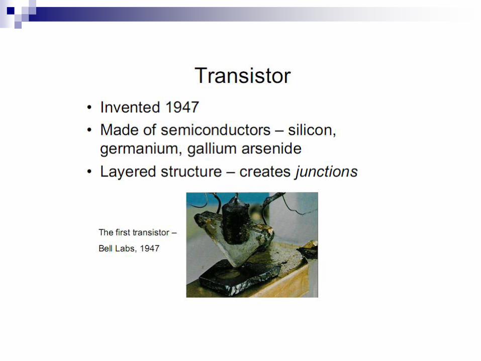


Solid State Discrete Op-Amps Solid state op amps invented in
1960’s
Possible due to invention of silicon transistors and the IC
Chip and discrete parts
Reduced power input to ±15V to ±10V
Packaging in small black boxes allowed for integration with a circuit

Monolithic Integrated Circuit Op-Amp
First created in 1963
μA702 by Fairchild Semiconductor
μA741 created in 1968
Became widely used due to its
ease of use
8 pin, dual in-line package (DIP)
Further advancements include
use of field effects transistors
(FET), greater precision, faster
response, and smaller packaging


Features of Op-Amps
+Vin: non-inverting input
-Vin: inverting input
+Vs: positive source
-Vs: negative source
Vout: output voltage
ON: Offset Null
NC: Not Connected
Vout
+Vs
-Vs
+Vin
-Vin
+
-
ON
-Vin
+Vin
-Vs ON
Vout
+Vs
NC


Characteristics of Op-Amps Ideal Op-Amp
Infinite open loop gain (GOL): Zero common mode gain
Infinite bandwidth: Range of frequencies
with non-zero gain
Real Op-Amp
Limited open loop gain: Decreases with increase
in frequency
Non-zero common mode gain
Limited Bandwidth:
Gain becomes zero at high frequencies

Characteristics of Op-Amps Ideal Op-Amp
Infinite slew rate
Infinite input impedance No input current
Zero output impedance Infinite output current
Real Op-Amp
Finite slew rate
Large input impedance Small input current
Non-zero output
impedance Limited output current

The open-loop gain of an operational amplifier is the gain
obtained when no feedback is used in the circuit. Open loop
gain is usually exceedingly high; in fact, an ideal operational
amplifier has infinite open-loop gain.
The slew rate of an electronic circuit is defined as the
maximum rate of change of the output voltage. Slew rate is
usually expressed in units of V/µs

An ideal op-amp is usually considered to have the following properties, and they are
considered to hold for all input voltages:
1. Infinite open-loop gain (when doing theoretical analysis, a limit may be taken as open
loop gain AOL goes to infinity).
2. Infinite voltage range available at the output () (in practice the voltages available from
the output are limited by the supply voltages and ). The power supply sources are
called rails.
3. Infinite bandwidth (i.e., the frequency magnitude response is considered to be flat
everywhere with zero phase shift).
4. Infinite input impedance (so, in the diagram, , and zero current flows from to ).
5. Zero input current (i.e., there is assumed to be no leakage or bias current into the
device).
6. Zero input offset voltage (i.e., when the input terminals are shorted so that , the output
is a virtual ground or ).
7. Infinite slew rate (i.e., the rate of change of the output voltage is unbounded) and
power bandwidth (full output voltage and current available at all frequencies).
8. Zero output impedance (i.e., , so that output voltage does not vary with output current).
9. Zero noise.
10. Infinite Common-mode rejection ratio (CMRR).
11. Infinite Power supply rejection ratio for both power supply rails.

These ideals can be summarized by the two "golden rules":
1. The output attempts to do whatever is necessary to make
the voltage difference between the inputs zero.
2. The inputs draw no current.
The first rule only applies in the usual case where the op-amp is
used in a closed-loop design (negative feedback, where there is a
signal path of some sort feeding back from the output to the
inverting input). These rules are commonly used as a good first
approximation for analyzing or designing op-amp circuits.
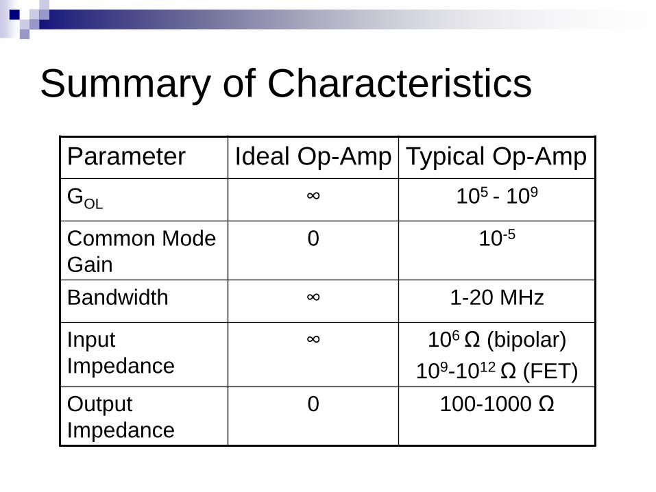
Summary of Characteristics
Parameter Ideal Op-Amp Typical Op-Amp
GOL ∞ 105 - 109
Common Mode
Gain
0 10-5
Bandwidth ∞ 1-20 MHz
Input
Impedance
∞ 106 Ω (bipolar)
109-1012 Ω (FET)
Output
Impedance
0 100-1000 Ω

Ideal Op-Amp
Active device
Infinite open loop gain
Infinite input impedance
Zero output impedance
+
-
+Vs
-Vs
Vdiff
iin = 0A
Vout = Vdiff x Gopenloop


Negative Feedback
Vout is a linear function of the input voltage
Zin = infinity Iin=0A Vdiff=0V
Modelisation of basic mathematical
operation


Non Inverting Circuit
+
-
R1 R2
+Vs
-Vs
iin = 0A
Vdiff = 0V Vin
Vout
0A
V- V- - Vout
i
(1) V- - Vout = R2 x i
(2) V- = - R1 x i
V- = V+ = Vin
(2) i = -Vin/R1
(1) Vin – Vout = -Vin x R1/R2
Vout = (1 + R1/R2) x Vin

Inverting Circuit
+
-
R1 R2
+Vs
-Vs
Vdiff = 0V
Vin
Vout
iin = 0A
i
V- - Vout Vin – V-
(1) V- - Vout = R2 x i
(2) Vin - V- = R1 x i
V- = V+ = 0
(1) i = Vin / R1
Vout = - R2/R1 x Vin


Follower Circuit
- Vs


Summing Op-Amp • Adds analog signals
f
out
R
VV
R
VV
R
VV
R
VV
3
3
2
2
1
1
3
3
2
2
1
1
R
V
R
V
R
VRV fout
Solving for Vout:
Ohm’s Law:

Summing Op-Amp

Difference Op-Amps • Subtracts analog signals
1
1
32
124
413
)(V
R
RV
RRR
RRRVout
• Output voltage is proportional to
difference between input voltages:

Difference Op-Amp

Integrator Op-Amps •Similar layout to inverting op-amp,
but replace feedback resistor with
a capacitor
•A constant input signal generates
a certain rate of change in output
voltage
• Smoothes signals over time
t
ininitialoutfinalout dtVRC
VV0
,,
1
•Output voltage is proportional to
the integral of the input voltage:

Integrator Op-Amp

Differentiating Op-Amp •Similar to inverting op-amp, but
input resistor is replaced with a
capacitor
•Accentuates noise over time
dt
dVRCV in
out
• Output signal is scaled
derivative of input signal:

Differentiating Op-Amp

Active Filters
Different types of active filters:
Low Pass
Filters out frequencies above a cutoff frequency
High Pass
Filters out frequencies below a cutoff frequency
Band Pass
Passes a range of frequencies between two cutoff
frequencies

Active Low-Pass Filter
Cutoff frequency:
CRc
2
1

Active High-Pass Filter
Switch positioning of capacitors and resistors from low-
pass filter locations to create high-pass filter.

Active Band-Pass Filter
Created by connecting output of a high-pass filter to the input of a low-pass filter or vice versa.
Also can create using only 1 op-amp with feedback and input capacitors

No negative feedback
Vout is a non-linear function of the differential input voltage V+ - V-
V+ - V- = Vdiff
Vout = sign(Vdiff) x Vs
Binary logic and oscillator

Comparator
+
-
+Vs
-Vs
iin = 0A
Vdiff
V+
V-
Vout
0V
+ Vs
Vout ( volts )
Vdiff
- Vs

Comparator

Common-Mode Input Resistance (RINCM)
For op amps operating in the linear region, this term defines the input
common-mode voltage range divided by the change in input bias current
across that range.
2. DC Common-Mode Rejection (CMRDC)
This is a measure of the op amp's ability to reject DC signals present in
equal measure at both inputs.
CMRDC can be calculated using the common-mode voltage range (CMVR)
and the change in peak-topeak input offset voltage across that range.

References
“Operational Amplifiers.” http://en.wikipedia.org/wiki/Op_amp
“Real vs. Ideal Op Amp.” http://hyperphysics.phy-astr.gsu.edu/hbase/electronic/opamp.html#c4
“741 Op Amp Tutorial.” http://www.uoguelph.ca/~antoon/gadgets/741/741.html
“Op Amp History.” Analog Devices. http://www.analog.com/library/analogDialogue/archives/39-05/Web_ChH_final.pdf