opc-server ethernet - softing · opc-server ethernet we have checked the contents of the document...
TRANSCRIPT
© Softing Industrial Networks GmbH 2012
Multi-Protocol OPC Server Ethernet with integrated DCOM Tunnel (OPCpipe)
Version: E-032012-01
OPC-Server Ethernet
We have checked the contents of the document for conformity with the hardware and software described.Nevertheless, we are unable to preclude the possibility of deviations so that we are unable to assume warranty for fullcompliance. The information given in the publication is,however, reviewed regularly. Necessary amendments are incorporated in the following editions. We would be pleased to receive any improvement proposals which you may have. This document may not be passed on nor duplicated, nor may its contents be used or disclosed unless expresslypermitted. Violations of this clause will necessarily lead to compensation in damages.
All rights reserved, in particular rights of granting of patents or registration ofutility-model patents.
© Softing Industrial Networks GmbH 2012. All rights reserved.
Disclaimer of liability
Softing Industrial Networks GmbH
Ostendstr. 50 A
D-90482 Nürnberg
Tel: + 49 (0)911 544 27-0
Fax: + 49 (0)911 544 27-27
Internet: www.softing-in.de
Email: [email protected]
Important notes
ead the manual before the start. For damages due to improper connection, implementation or operationSofting refuses any liability according to our existing guarantee obligations.
The recent version of this manual is available in the Download Area of the Softing at:www.softing-in.de.
Table of Contents 3
OPC-Server Ethernet - Manual / Table of Contents 3
Table of Contents
Chapter 1 Help-Overview 7
Chapter 2 INAT OPC Server – General 9
................................................................................................................................... 92.1 Overview
................................................................................................................................... 102.2 System Prerequisites
................................................................................................................................... 102.3 License Requirements
................................................................................................................................... 122.4 Server Revision
Chapter 3 The Basics 14
................................................................................................................................... 143.1 DCOM
.......................................................................................................................................................... 14What Is DCOM? 3.1.1
.......................................................................................................................................................... 15DCOM Configuration – General 3.1.2
.......................................................................................................................................................... 16DCOM Configuration: Server Computer 3.1.3
......................................................................................................................................................... 16Workplace Settings3.1.3.1
......................................................................................................................................... 16General
......................................................................................................................................... 16Options
......................................................................................................................................... 16Standard Properties
......................................................................................................................................... 16Standard Protocols
......................................................................................................................................... 16MSDTC
......................................................................................................................................... 16Standard Security
......................................................................................................................................................... 16OPC Server Settings3.1.3.2
......................................................................................................................................... 17General
......................................................................................................................................... 17Execution Location
......................................................................................................................................... 17Security
......................................................................................................................................... 18End points
......................................................................................................................................... 18Identity
.......................................................................................................................................................... 19DCOM Configuration: Client Computer 3.1.4
......................................................................................................................................................... 19Options3.1.4.1
......................................................................................................................................................... 19Standard Characteristics3.1.4.2
......................................................................................................................................................... 19Standard Protocols3.1.4.3
......................................................................................................................................................... 19MSDTC3.1.4.4
......................................................................................................................................................... 19Standard Security3.1.4.5
................................................................................................................................... 203.2 OPC Basics
.......................................................................................................................................................... 20What Is OPC? 3.2.1
.......................................................................................................................................................... 21OPC DA Specification 3.2.2
................................................................................................................................... 233.3 PLC Connections
.......................................................................................................................................................... 23S7 - General Information 3.3.1
.......................................................................................................................................................... 24S5 - General Information 3.3.2
.......................................................................................................................................................... 24Modbus - General Information 3.3.3
.......................................................................................................................................................... 25CLX - General Information 3.3.4
.......................................................................................................................................................... 25PLC-5/SLC - General Information 3.3.5
.......................................................................................................................................................... 25netLINK - General Information 3.3.6
.......................................................................................................................................................... 26MELSEC-Q - General Information 3.3.7
.......................................................................................................................................................... 26Send/Receive – General Information 3.3.8
.......................................................................................................................................................... 27OPCpipe – General Information 3.3.9
OPC-Server Ethernet - Manual / Table of Contents
Table of Contents4
4
Chapter 4 Operation and configuration 29
................................................................................................................................... 304.1 How To Proceed
................................................................................................................................... 314.2 Licensing
................................................................................................................................... 324.3 Tool Bar
................................................................................................................................... 334.4 Screens
.......................................................................................................................................................... 33Online Diagnosis 4.4.1
.......................................................................................................................................................... 36Access Path List 4.4.2
.......................................................................................................................................................... 37Logger 4.4.3
.......................................................................................................................................................... 38Configuration 4.4.4
................................................................................................................................... 394.5 Connection (Access Path)
.......................................................................................................................................................... 39New Connection (Access Path) 4.5.1
.......................................................................................................................................................... 40Network Protocol 4.5.2
.......................................................................................................................................................... 41OPC Server Connection 4.5.3
......................................................................................................................................................... 44IP Address4.5.3.1
......................................................................................................................................................... 45Port4.5.3.2
......................................................................................................................................................... 45TSAP4.5.3.3
......................................................................................................................................................... 46TSAP for S7 connections4.5.3.4
......................................................................................................................................................... 47Routing TSAPs4.5.3.5
......................................................................................................................................................... 48Events from the PLC4.5.3.6
......................................................................................................................................................... 48Modbus Protocol Settings4.5.3.7
......................................................................................................................................................... 49CLX Protocol Settings4.5.3.8
......................................................................................................................................................... 50Melsec-Q Protocol Settings4.5.3.9
.......................................................................................................................................................... 51Edit Connection 4.5.4
......................................................................................................................................................... 51Server settings4.5.4.1
......................................................................................................................................................... 51Network TCP/IP parameters4.5.4.2
......................................................................................................................................................... 52OPCpipe Parameters4.5.4.3
.......................................................................................................................................................... 52Copy connection 4.5.5
.......................................................................................................................................................... 53Delete connection 4.5.6
.......................................................................................................................................................... 53Switching a Connection Inactive 4.5.7
................................................................................................................................... 544.6 Configuration
.......................................................................................................................................................... 55Server System Settings 4.6.1
.......................................................................................................................................................... 58Logger Settings 4.6.2
.......................................................................................................................................................... 59Logger Memory Settings 4.6.3
.......................................................................................................................................................... 60Station Password 4.6.4
.......................................................................................................................................................... 60H1 MAC Address 4.6.5
.......................................................................................................................................................... 61Server Symbol Edit 4.6.6
.......................................................................................................................................................... 62S7 Symbol Import 4.6.7
.......................................................................................................................................................... 63AB ControlLogiX Symbol Import 4.6.8
.......................................................................................................................................................... 63Modbus Symbol Import 4.6.9
.......................................................................................................................................................... 65Directory for Configuration File 4.6.10
................................................................................................................................... 664.7 Dialog Screens
.......................................................................................................................................................... 66Network Settings (Station Parameters) 4.7.1
.......................................................................................................................................................... 67Versions 4.7.2
.......................................................................................................................................................... 67License Overview 4.7.3
.......................................................................................................................................................... 67License entry 4.7.4
.......................................................................................................................................................... 68About 4.7.5
.......................................................................................................................................................... 68Entering the Password 4.7.6
.......................................................................................................................................................... 68Selecting the Stations 4.7.7
.......................................................................................................................................................... 69New Station 4.7.8
.......................................................................................................................................................... 70Station not found 4.7.9
Table of Contents 5
OPC-Server Ethernet - Manual / Table of Contents 5
................................................................................................................................... 714.8 Menu
.......................................................................................................................................................... 71File 4.8.1
.......................................................................................................................................................... 71Connection 4.8.2
.......................................................................................................................................................... 72Diagnostics 4.8.3
.......................................................................................................................................................... 72Station 4.8.4
.......................................................................................................................................................... 73Settings 4.8.5
.......................................................................................................................................................... 73Symbols 4.8.6
.......................................................................................................................................................... 74Help 4.8.7
................................................................................................................................... 754.9 Troubleshooting
Chapter 5 Accessories 77
................................................................................................................................... 775.1 NetCon OPC
................................................................................................................................... 795.2 Selecting the Server Type
................................................................................................................................... 805.3 Server Tray
................................................................................................................................... 805.4 Logger
................................................................................................................................... 815.5 OPC Client
Chapter 6 Item Syntax 83
................................................................................................................................... 846.1 S7 Item Syntax
................................................................................................................................... 886.2 S5 Item Syntax
................................................................................................................................... 926.3 Modbus Item Syntax
................................................................................................................................... 956.4 PLC-5 / SLC Item Syntax
................................................................................................................................... 976.5 MELSEC-Q Item Syntax
................................................................................................................................... 1006.6 Send/Receive Item Syntax
................................................................................................................................... 1026.7 OPCpipe Item Syntax
................................................................................................................................... 1036.8 Arrays
................................................................................................................................... 1046.9 Suffixe
................................................................................................................................... 1076.10 Data Types
................................................................................................................................... 1086.11 Special Items
Index 114

Help-Overview
Chapter 1
7Help-Overview
OPC-Server Ethernet - Benutzerhandbuch / Help-Overview 7
1 Help-Overview
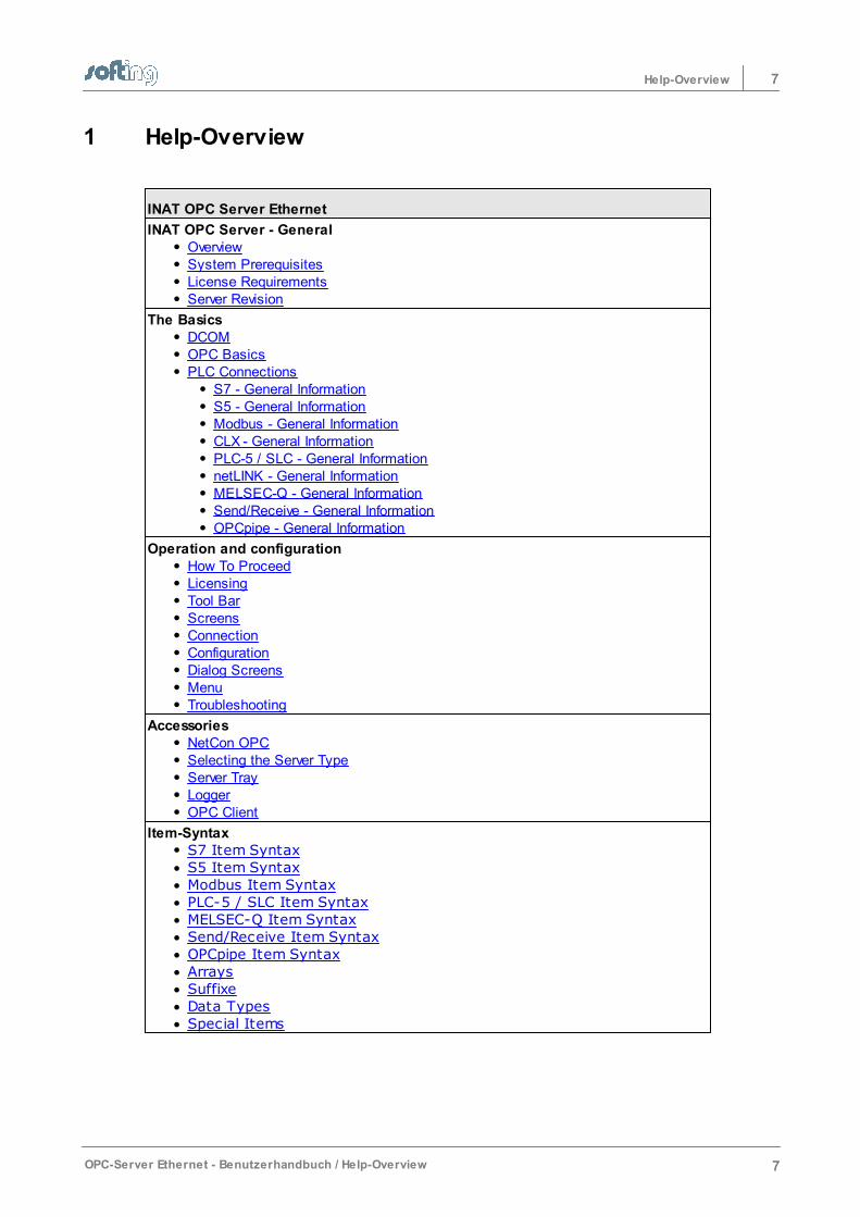
INAT OPC Server Ethernet
INAT OPC Server - GeneralOverviewSystem PrerequisitesLicense RequirementsServer Revision
The BasicsDCOMOPC BasicsPLC Connections
S7 - General InformationS5 - General InformationModbus - General InformationCLX - General InformationPLC-5 / SLC - General InformationnetLINK - General InformationMELSEC-Q - General InformationSend/Receive - General InformationOPCpipe - General Information
Operation and configurationHow To ProceedLicensingTool BarScreensConnectionConfigurationDialog ScreensMenuTroubleshooting
AccessoriesNetCon OPCSelecting the Server TypeServer TrayLoggerOPC Client
Item-SyntaxS7 Item SyntaxS5 Item SyntaxModbus Item SyntaxPLC-5 / SLC Item SyntaxMELSEC-Q Item SyntaxSend/Receive Item SyntaxOPCpipe Item SyntaxArraysSuffixeData TypesSpecial Items

INAT OPC Server – General
Chapter 2
9INAT OPC Server – General
OPC-Server Ethernet - Benutzerhandbuch / INAT OPC Server – General 9
2 INAT OPC Server – General
This chapter describes the following subjects:
OverviewSystem PrerequisitesLicense RequirementsServer Revision
2.1 Overview
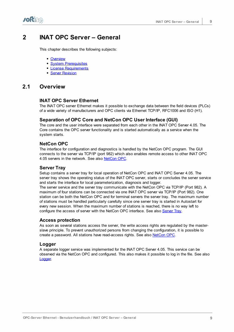
INAT OPC Server EthernetThe INAT OPC server Ethernet makes it possible to exchange data between the field devices (PLCs)of a wide variety of manufacturers and OPC clients via Ethernet TCP/IP, RFC1006 and ISO (H1).
Separation of OPC Core and NetCon OPC User Interface (GUI)The core and the user interface were separated from each other in the INAT OPC Server 4.05. TheCore contains the OPC server functionality and is started automatically as a service when thesystem starts.
NetCon OPCThe interface for configuration and diagnostics is handled by the NetCon OPC program. The GUIconnects to the server via TCP/IP (port 982) which also enables remote access to other INAT OPC4.05 servers in the network. See also NetCon OPC.
Server TraySetup contains a server tray for local operation of NetCon OPC and INAT OPC Server 4.05. Theserver tray shows the operating status of the INAT OPC server, starts or concludes the server serviceand starts the interface for local parameterization, diagnosis and logger. The server service and the server tray communicate with the NetCon OPC via TCP/IP (Port 982). Amaximum of four stations can be connected via one INAT OPC server via TCP/IP (Port 982). Onestation can be both the NetCon OPC and for terminal servers the server tray. The maximum numberof stations must be handled particularly carefully since one server tray is started in Autostart forevery new session. When the maximum number of stations is reached, there is no way left toconfigure the access of server with the NetCon OPC interface. See also Server Tray.
Access protectionAs soon as several stations access the server, the write access rights are regulated by the master-slave principle. To prevent unauthorized persons from changing the configuration, it is possible tocreate a password. All stations have read-access rights. See also NetCon OPC.
LoggerA separate logger service was implemented for the INAT OPC Server 4.05. This service can beobserved via the NetCon OPC and configured. This also makes it possible to log in the file. See also Logger.
10 INAT OPC Server – General
10 OPC-Server Ethernet - Benutzerhandbuch / INAT OPC Server – General
2.2 System Prerequisites
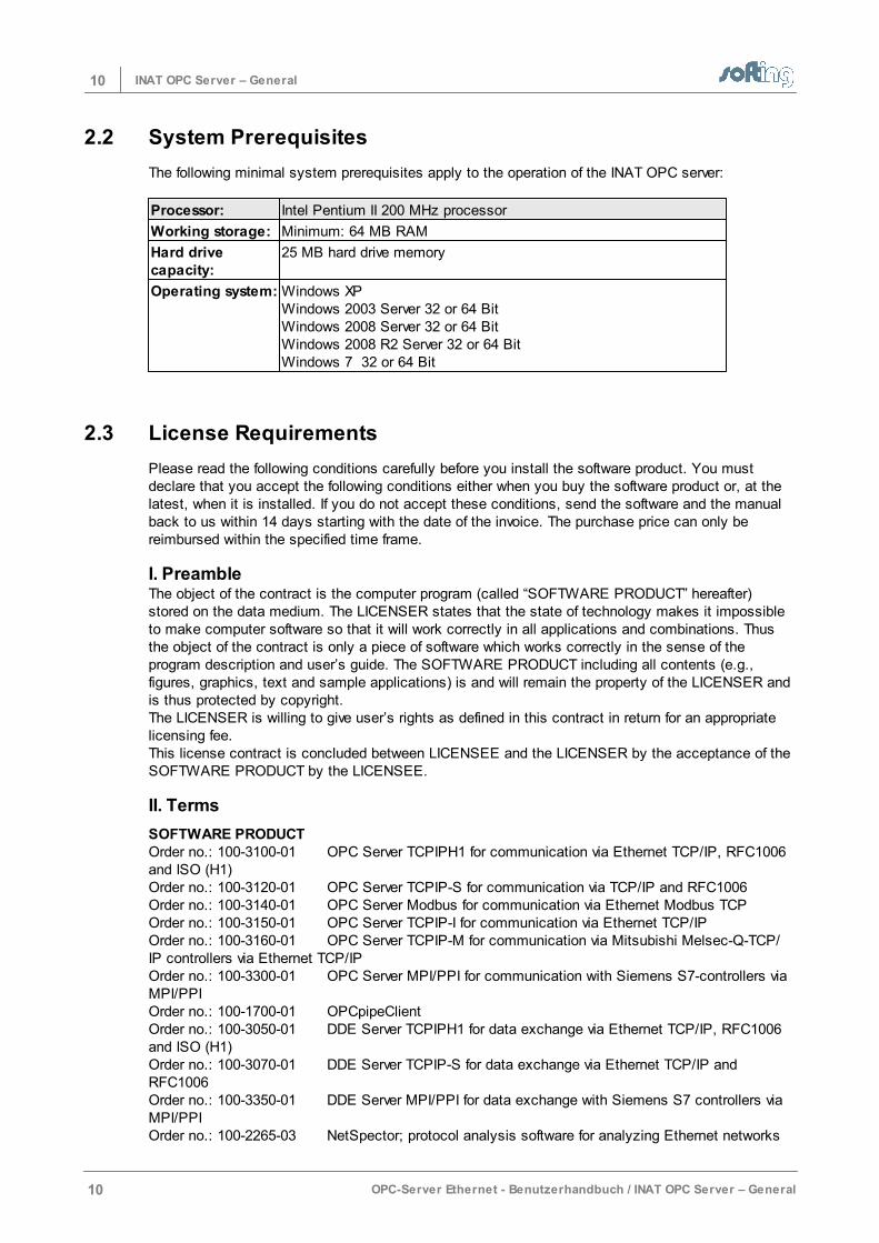
The following minimal system prerequisites apply to the operation of the INAT OPC server:
Processor: Intel Pentium II 200 MHz processor
Working storage: Minimum: 64 MB RAM
Hard drivecapacity:
25 MB hard drive memory
Operating system: Windows XPWindows 2003 Server 32 or 64 BitWindows 2008 Server 32 or 64 BitWindows 2008 R2 Server 32 or 64 BitWindows 7 32 or 64 Bit
2.3 License Requirements
Please read the following conditions carefully before you install the software product. You mustdeclare that you accept the following conditions either when you buy the software product or, at thelatest, when it is installed. If you do not accept these conditions, send the software and the manualback to us within 14 days starting with the date of the invoice. The purchase price can only bereimbursed within the specified time frame.
I. PreambleThe object of the contract is the computer program (called “SOFTWARE PRODUCT” hereafter)stored on the data medium. The LICENSER states that the state of technology makes it impossibleto make computer software so that it will work correctly in all applications and combinations. Thusthe object of the contract is only a piece of software which works correctly in the sense of theprogram description and user’s guide. The SOFTWARE PRODUCT including all contents (e.g.,figures, graphics, text and sample applications) is and will remain the property of the LICENSER andis thus protected by copyright. The LICENSER is willing to give user’s rights as defined in this contract in return for an appropriatelicensing fee. This license contract is concluded between LICENSEE and the LICENSER by the acceptance of theSOFTWARE PRODUCT by the LICENSEE.
II. Terms
SOFTWARE PRODUCTOrder no.: 100-3100-01 OPC Server TCPIPH1 for communication via Ethernet TCP/IP, RFC1006and ISO (H1)Order no.: 100-3120-01 OPC Server TCPIP-S for communication via TCP/IP and RFC1006Order no.: 100-3140-01 OPC Server Modbus for communication via Ethernet Modbus TCP Order no.: 100-3150-01 OPC Server TCPIP-I for communication via Ethernet TCP/IPOrder no.: 100-3160-01 OPC Server TCPIP-M for communication via Mitsubishi Melsec-Q-TCP/IP controllers via Ethernet TCP/IPOrder no.: 100-3300-01 OPC Server MPI/PPI for communication with Siemens S7-controllers viaMPI/PPIOrder no.: 100-1700-01 OPCpipeClientOrder no.: 100-3050-01 DDE Server TCPIPH1 for data exchange via Ethernet TCP/IP, RFC1006and ISO (H1)Order no.: 100-3070-01 DDE Server TCPIP-S for data exchange via Ethernet TCP/IP andRFC1006Order no.: 100-3350-01 DDE Server MPI/PPI for data exchange with Siemens S7 controllers viaMPI/PPIOrder no.: 100-2265-03 NetSpector; protocol analysis software for analyzing Ethernet networks
11INAT OPC Server – General
OPC-Server Ethernet - Benutzerhandbuch / INAT OPC Server – General 11
The modules can be purchased individually or in different combinations. The licensing contractapplies the same to each individual version. This is why the term SOFTWARE PRODUCT is used forall versions in this manual.
LICENSERSofting Industrial Networks GmbHOstendstraße 50AD-90482 Nürnberg
LICENSEENatural or legal persons who purchase this license for the purpose of using the SOFTWAREPRODUCT.
THIRD PARTIESOther natural or legal persons.
III. Scope1. The SOFTWARE PRODUCT is exclusively licensed for use by the LICENSEE. The LICENSEE
may sell the SOFTWARE PRODUCT to THIRD PARTIES under the condition that the THIRDPARTY agrees to this software licensing contract. In this case, the software license contract isinvalid for the LICENSEE and the utilization rights to the SOFTWARE PRODUCT are cancelled forhim since these rights have been passed on to a THIRD PARTY who has now become theLICENSEE him/herself.
2. The SOFTWARE PRODUCT may only be used on a single computer. The LICENSEE is obligatedto purchase a separate license for every computer on which the SOFTWARE PRODUCT is used.A different agreement between LICENSEE and LICENSER applies to the purchase of multiple andnetwork licenses.
3. The duplication of the SOFTWARE PRODUCT and all related documentations is forbidden exceptfor the creation of an archive copy for exclusive use by the LICENSEE. If the LICENSEE’s original data medium becomes defective, it can be exchanged at theLICENSER for a replacement data medium. The cost of the exchange will be carried by theLICENSEE.
4. The SOFTWARE PRODUCT is delivered on data medium as a demo version with restrictedfunction scope.The demo version may not be used for commercial purposes. After payment of the licensing feefor the particular desired version, the LICENSEE will receive a code number from the LICENSERfor the release of the corresponding SOFTWARE PRODUCT.
5. If a new program version is given to the LICENSEE due to the purchase of an update or for anyother reason, the user’s rights for the earlier program versions become void. This means that youmay only work with the latest version.
6. The LICENSEE and THIRD PARTIES are forbidden to modify the SOFTWARE PRODUCT orreverse engineer it (i.e., de-compile or disassemble it). The LICENSEE is liable for all damages which occur because of the violation of these conditions.
IV. Limited WarrantyThe data carriers on which the SOFTWARE PRODUCT was delivered are free from material andmanufacturer’s flaws during normal use during a period of time of 6 months starting on the deliverydate. The data carriers are free of viruses according to the LICENSER. If, however hidden viruseshave snuck in, the LICENSER will not be liable for any subsequent damages which may occur.1. The preceding limited warranty does not cover data carriers which have been damaged by chance
or misuse or manipulation of unauthorized parties (people other than employees of theLICENSER).
2. During the stated guarantee period, the LICENSER is obligated to replace a defective data carrierif this was sent to the LICENSER with a copy of the invoice. Other claims, in particular damageclaims, will not be honored subject to para. 4 and Roman numeral V.
3. No further guarantee claims will be allowed. In particular, no guarantee claims will be accepted for
12 INAT OPC Server – General
12 OPC-Server Ethernet - Benutzerhandbuch / INAT OPC Server – General
program content and its freedom from errors or suitability for certain purposes. The responsibilityfor software and hardware selection, for installation, use, expected results and data protection anddata backup with backup copies is the exclusive business of the LICENSEE.
4. Exceptions to the preceding warranty restrictions are promised characteristics. These promisesmust be in writing to be valid and accompanied by the signature of the authorized representative ofthe LICENSER. The LICENSER is only liable for damage claims in accordance with Romannumeral V.
V. RESTRICTION OF LIABILITY 1. The LICENSER is not liable for damages unless the damage is caused by intent or grossnegligence of the LICENSER.2. Liability due to any characteristics which may have been promised by the LICENSER is notaffected by this. Liability for subsequent damages due to deficiencies which were not included in thepromises of the LICENSER are excluded. 3. No liability is assumed for calculable damages, in particular lost profit.4. Any damage claims are limited to the amount of the damage whose possible occurrence theLICENSER logically had to expect under the circumstances known at that time when the contractwas concluded. In any case, liability is limited to the amount of twice the purchase price that waspaid (license fee), regardless of whether claims pertaining to contract law, damage claims or otherliability claims are concerned.
VI. Validity and Conclusion1. The license given to the LICENSEE is valid until it is terminated by the licensee or the
LICENSER. 2. The LICENSEE can terminate the license at all times by returning the SOFTWARE PRODUCT
including the archivation copy and all related documentation to the LICENSER. If the return is not due to a warranty claim, the license fee will not be reimbursed.
3. No liability is assumed for calculable damages, in particular lost profit.4. The LICENSEE terminates the license by resale to a THIRD PARTY in accordance with III, para.
1.
VII. Applicable Laws1. Regarding the laws which may apply, this license is subject to the laws of the Federal Republic of
Germany and the exclusive adjudication of the German courts of law. 2. Court of jurisdiction for all legal disputes resulting from the contractual relationship and its creation
and effectiveness for general merchants is Nuremberg. However, the LICENSER has the right totake the LICENSEE to court at his location.
3. Place of execution for all obligations from this contractual relationship is Nuremberg.
2.4 Server Revision
The revision of the server is located in the installation directory of the server in either the file revision_opc_d.htm or revision_opc_e.htm.

The Basics
Chapter 3
14 The Basics
14 OPC-Server Ethernet - Benutzerhandbuch / The Basics
3 The Basics
This chapter describes the following subjects:
DCOMOPC BasicsPLC Connections
3.1 DCOM
This chapter describes the following subjects:
What is DCOM?DCOM configurationDCOM Configuration: Server ComputerDCOM Configuration: Client Computer
3.1.1 What Is DCOM?
DCOM (Distributed Component Object Model) is an object-oriented RPC system which is based onthe DCE standard. It was defined by Mircosoft so that COM technology could communicate via anetwork. DCOM (Distributed Component Object Model) is an expansion of COM. While COM makesthe communication of objects on a computer possible, objects which are located on differentcomputers can also use DCOM to communicate with each other. DCOM enables COM callsbetween distribution computers within one network.
In addition to COM technology, OPC also uses DCOM to achieve network capability. This meansthat not only are the services of the OPC server which are located on the local PC available to anOPC client but also the services of all OPC servers in the network.
DCOM is always used then when client and server are located on different computers (i.e., remoteservers).
Several settings in DCOM configuration are necessary so that client and server can communicatewith each other via DCOM.
When more security is needed on a PC, the DCOM settings must also be changed when OPCserver and OPC client are running on one PC.
NOTE:
One way to get around DCOM and the time-consuming configuration is to use the OPCpipe.
15The Basics
OPC-Server Ethernet - Benutzerhandbuch / The Basics 15
3.1.2 DCOM Configuration – General
DCOM has been available on all Windows platforms since Windows NT.
The program dcomcnfg.exe is available to make changes to the DCOM configuration.
The DCOM configuration is started via one of the following: Calling the menu Settings - DCOM settings of NetCon OPC By entering "DCOMCNFG" in the command line of the promptVia System control - Administration – Component Services.
The start rights should be set correctly on the OPC server so that the OPC server can be startedautomatically by the OPC client.
NOTE:
The registered user must have administrator rights before he/she can change the DCOMconfiguration.
NOTE:
Use of the OPCpipe is one way to get around the DCOM and thus the time-consumingconfiguration.
OPC server and OPC client on the same computerIf you want to use the OPC server as a service, it is mandatory that the interactive user be enteredas standard in the access rights of the global COM security settings.
OPC server and OPC client on different computersThe DCOM configuration must be adapted on both the server computer and the client computer.
16 The Basics
16 OPC-Server Ethernet - Benutzerhandbuch / The Basics
3.1.3 DCOM Configuration: Server Computer
The server computer is the computer on which the OPC server is running.
NOTE:
The registered user must have administrator rights before he/she can change the DCOMconfiguration.
Both "Properties of INAT OPC server" and "Workplace Settings" must be adapted on the server side.
3.1.3.1 Workplace Settings
The workplace settings are made by browsing in Console master via Component services >Computer > Workplace. One click with the right mouse button on Workplace opens the menuand permits Properties to be processed.
3.1.3.1.1 General
No changes are necessary for the General settings. The default setting can be used.
3.1.3.1.2 Options
No changes are necessary for the Options settings. The default setting can be used.
3.1.3.1.3 Standard Properties
Standard authentication level: Connect
Standard identification change level: Identify
3.1.3.1.4 Standard Protocols
Connection-oriented TCP/IP should be listed first for the Standard protocols.This setting is used to handle the DCOM connections via TCP/IP.
3.1.3.1.5 MSDTC
No changes are necessary for the "MSDTC" settings. The default setting can be used.
3.1.3.1.6 Standard Security
Access rights:The users who are allowed to access the application can be specified for applications which do notprovide access rights settings themselves.
Start rights:The users who are allowed to start the application can be specified for applications which do notprovide start rights settings themselves.
LimitsThe limits can be set for applications which change the rights.
3.1.3.2 OPC Server Settings
The OPC server settings are made by browsing in Console master via > Component services >Computer > Workplace > DCOM configuration > INAT TcpIpH1 OPC Server. A click with the right mouse button on INAT TcpIpH1 OPC Server opens the menu and permitsProperties to be accessed.
17The Basics
OPC-Server Ethernet - Benutzerhandbuch / The Basics 17
3.1.3.2.1 General
No changes are necessary for the General settings. The default setting Authentication level =Standard can be used.
3.1.3.2.2 Execution Location
No changes are necessary for the Execution Location settings. The default setting can be used.
3.1.3.2.3 Security
The security settings for the start, access and configuration of the OPC server are set here. The appropriate rights are specified with the "Edit" button.
START RIGHTS
These rights are changed as shown below:Pressing the "Edit" button.Clicking the "Add" button to add group or user names. Click the "Path" button.Start rights should be assigned for: o Administrators
o ANONYMOUS
o SERVICE
o INTERACTIVE
o NETWORK
o SYSTEM
o The user who starts the client
Highlight the desired names and press the "OK" button.Then select each one separately in the list and click "Permit" for all possibilities.Then click the "OK" button.
ACCESS RIGHTS
The access rights are changed the same way the start rights are changed. Access rights should be provided for:
o Administrators
o ANONYMOUS
o SERVICE
o INTERACTIVE
o NETWORK
o SYSTEM
o The user who starts the client
Highlight the desired names and press the "OK" button.Then select each one separately in the list and click "Permit" for all possibilities.Then click the "OK" button.
CONFIGURATION RIGHTS
Proceed as described for ACCESS RIGHTS.
These settings will work with most OPC clients. If access by another user is also desired, this usercan still be added. If access is to be further limited, the applicable entry can be removed.
18 The Basics
18 OPC-Server Ethernet - Benutzerhandbuch / The Basics
NOTE:
Some changes do not take effect until after a new start of the PC although no specialmessage is output.
Alternate action: The standards can be adjusted and Standard can be selected at the top.
3.1.3.2.4 End points
No changes are required in the "End points" settings. The default setting "Standard systemprotocols" can be used. This means that the protocols are used which are set under Standard protocols.
3.1.3.2.5 Identity
No changes are required in the "Identity" settings. The default setting "Interactive user" should beused.
Interactive user:The interactive user is the user who is logged in at the moment. This is the only way that the OPCserver can be made available to additional clients.
User who starts the application:This setting should not be used. The security settings of the client application will be used instead.
This user:The server will use the security settings of the specified person. Every time the server is started, thesecurity settings of the specified person are used. If this is the case, start rights must only be given to this person on the client side. The user “Interactive User” is set as the default during installation.
System account (only for service):This setting can be selected if the server is being run as a service.
NOTE:
All settings except "Interactive user" and "System account" start the OPC server in anown process area. An additional server then starts the OPC server again. Then the clients do not use the same information.
19The Basics
OPC-Server Ethernet - Benutzerhandbuch / The Basics 19
3.1.4 DCOM Configuration: Client Computer
The client computer is the computer on which the OPC client is running.
NOTE:
The registered user must have administrator rights before he/she can change the DCOMconfiguration.
The work place settings are made by browsing in the console master and going to > Componentservices > Computer > Work place. Click once with the right-hand mouse button on Work placeto open the menu so that you can process the Properties.
3.1.4.1 Options
No changes are required in the "Options" settings. The default setting can be used.
3.1.4.2 Standard Characteristics
"Activate DCOM on this computer" should be activated. The standard authentication level and thestandard identity level should be set as shown below:
Client computer in one work group:Authentification level: None Identity change level: Anonymous
Client computer in one domain:Authentification level: Connect Identity change level: Identification
Client computer in a mixed configuration (Client computer in a work group, Servercomputer in a domain): Authentication level: None Identity change level: Anonymous
3.1.4.3 Standard Protocols
The "Connection-oriented TCP/IP" should be preferred of all the standard protocols. When thissetting is selected, DCOM connections are handled via TCP/IP.
3.1.4.4 MSDTC
No changes are required with the "MSDTC" settings. The default setting can be used.
3.1.4.5 Standard Security
The "Start and activation rights" and "Access rights" can be changed here for all COM objects. The settings must be changed in such a way that the client application can be started and accessedon the OPC server.
Start and access rights for: AdministratorsInteractive usersSystemNetworkor the Group or the User under which the OPC client is running
The Configuration rights do not need to be changed on the client computer.
20 The Basics
20 OPC-Server Ethernet - Benutzerhandbuch / The Basics
3.2 OPC Basics
This chapter describes the following subjects:
What Is OPC?OPC DA Specification
3.2.1 What Is OPC?
OPC (OLE for Process Control) is an open standard for the uniform access of different Windows-based software applications (HMI, table calculation, archivation software, and so on) on the variousdata sources at the automation level (PLC, scales, scanner, etc.). Before the OPC was introduced,one driver had to be provided for every single software application. This meant that controller Xrequired one driver for the connection to software application A, one driver for the connection tosoftware application B, one driver for the connection to application C, and so on. The data had to beprovided individually to each of the data sources (e.g., once for the inquiry of application A, once forthe inquiry of application B, once for the inquiry of application C, and so on). And naturally the samething applied to controller Y. One driver per application had to be provided here too. The number ofdrivers was further increased by different operating systems on the application side and differentcommunication protocols and bus systems on the hardware side.
A uniform solution was needed for the access of the software applications to the various datasources (i.e., a manufacturer-independent software interface). OPC is a manufacturer-independentinterface standard for automation technology which simplifies data communication significantly. Datacan be transferred with OPC to any data source to any application.
The OPC interface uses OLE mechanisms. In turn, the basis for OLE is COM.
COM (Component Object Model)Client / server architectureCOM defines a generally valid way to access softwareservices. COM objects are implemented within the server. TheCOM objects offer services via methods which arecombined in interfaces. Clients are applications which use the services of theobject by calling a method of an interface.
Manufacturers of the devices which supply process data provide an OPC server interface with themodule. The OPC server is responsible for the link to the data source. Manufacturers of applicationswhich record, visualize, etc. data provide an OPC client interface with the software application. Theclient can generate and utilize objects on the server via the OPC server interface.
21The Basics
OPC-Server Ethernet - Benutzerhandbuch / The Basics 21
3.2.2 OPC DA Specification
The OPC Foundation has defined a series of specifications, whereby each specification is providedfor a certain area of use. The OPC DA specification is the first specification of the OPC Foundationand is provided for process data communication. It defines an interface between client programs andserver programs for the data exchange. An OPC server allows one (or more) OPC client(s) to accessprocess data via this interface.
Class modelThe OPC specification for data access defines three hierarchical classes in the class model:OPCServer, OPCGroup and OPCItem.
The client program uses COM calls of the operating system to generate an object of the OPCServerclass. The other objects are generated by OPC methods.
Classes: OPCServerAn object of this class represents a manufacturer-specific OPC server. OPC servers implement thelink to the hardware and are provided with the process data (CPs, measuring devices, etc.) by themanufacturers of the modules. The manufacturer gives the OPC server an unambiguous name sothat it can be identified. This name is known as the ProgID in accordance with the COM standard.This program identifier contains a read-accessible string which describes the components. All typesof the INAT OPC server Ethernet have the following Prog.ID:
INAT TCPIPH1 OPC Server
The OPC server class contains methods which can be used by the client to administer objects of theOPCGroup class.
Class: OPCGroupAn object of this class structures the variables used by the OPC server. The OPCGroup administersthe individual process variables called the OPC items. With the aid of the OPCGroup, the client isable to create useful units of variables.
Class: OPCItemAn object of this class represents the actual process variable. The item in the address area of theOPC server is identified by its Item-ID (item syntax). An item is the connection to the data sourceand NOT the data source itself. Since the item ID is specified by the manufacturer of the server, itmust be unambiguous within the name area of the server. Each item has the following properties:
Value The last acquired value of the variable.
Quality Quality of the value
Time stamp Time at which the current value was determined for the first time.
Types of data accessData communication between the DA server and the DA client can be synchronous orasynchronous. The variables can also be observed. In addition, the values can be read out of cacheor directly out of the device.
Device The hardware itself
Cache Intermediate storage for all variables. An internal server image of the processdata.
22 The Basics
22 OPC-Server Ethernet - Benutzerhandbuch / The Basics
Read synchronouslyDuring synchronous communication, the client calls the SyncRead method and waits for the returnvalue. A new job cannot be started until this happens. The client is blocked as long as no returnvalue has been received from the server.
Write synchronouslyThe client sends a write job to the server. One or more items of a group are written with theSyncWrite method. The write operation does not return a result message unless the write operationwas not successful. To check whether the write operation was successful, the value must be readback immediately after the write access.
NOTE:
The synchronous access should be used in cases where an interruption of the userprogram plays a subordinate role.
Read and write asynchronously With asynchronous communication, the program that sent the asynchronous function call to accessprocess data receives a response message immediately as to whether the job was successfullygiven to the OPC server. The program then continues its work. The client receives the return valuefrom the server as soon as this is finished. The server calls the AsyncReadComplete /AsyncWriteComplete function of the OPC client.
NOTE:
Asynchronous accessing is helpful when large amounts of data are to be read and theuser program must react during processing.
Monitoring variablesDuring the monitoring of variables, all active OPC items in all active OPC groups are monitored. If avalue or the quality of a variable changes, the OPC client is informed of this. The client is notstrained during monitoring. The update rate must be set so that the client is not overloaded bychange messages when process variables are changing quickly.
NOTE:
Monitoring variables is helpful if the user program has to be informed at all times as tothe current value and the status of the data.
23The Basics
OPC-Server Ethernet - Benutzerhandbuch / The Basics 23
3.3 PLC Connections
This chapter describes the following subjects:
S7- General InformationS5 - General InformationModbus - General InformationCLX - General InformationPLC-5 / SLC - General InformationnetLINK - General InformationMELSEC-Q - General InformationSend/Receive General InformationOPCpipe - General Information
3.3.1 S7 - General Information
The S7 protocol is used for communication with S7 controllers and for communicationwith CPs which can handle the S7 protocol.The S7 protocol can be used in connection with both the TCP/IP and the H1. Read (fetch active) and write (write active)
With communication with S7 controllers, both read and write accesses canalways be performed via an access path. The S7 protocol is usually parameterized with RFC-1006. In addition to the address of the S7 controller (IP address or MAC address), a“TSAP for read and write accesses” is required. Data can be read and written from/to an S7 controller (layer 7 communication)using:
- Non-parameterizable access paths - Parameterizable access paths
Non-parameterizable access pathsAn access path is only set up on the OPC side – NEVER on the controller side. Standard access paths are required that are handled via standard TSAPs or standardports.There are only a limited number of standard access paths. If this is not enough,“parameterizable access paths” must be used.Standard access paths with Siemens CPs are handled by RFC1006 or H1 (see Standard-TSAPs and TSAP with S7 access paths). Parameterizable access pathsThe access path must be parameterized on both sides of the communication (a Fetch/Write active access path on the OPC server AND a Fetch/Write passive access pathfor the S7-CP). If communication uses echolink, parameterizable access paths arerequired.
NOTE:
Both the S7 Item Syntax and the S5 Item Syntax can be used for communication withS7 controllers.
24 The Basics
24 OPC-Server Ethernet - Benutzerhandbuch / The Basics
3.3.2 S5 - General Information
The S5 protocol is used for communication with S5 controllers (S5-AP header) and forcommunication with CPs which can handle the S5 protocol such as echolink andechocollect. The S5 protocol can be used both in connection with TCP/IP and with H1. Read (fetch active):_
A read connection is set up on the OPC server so that data can be actively readfrom an S5 controller.A “port for read accesses” or a “TSAP for read accesses” is required in additionto the address of the S5 controller (IP address or MAC address)The read connection must be parameterized on both sides of the communication(fetch active connection on the OPC server, fetch passive connection on theS5).
Write (write active):
If data is also to be written to the S5 controller, a write connection is set up inaddition to the read connection. The write connection path needs a “port for write accesses” or a “TSAP for writeaccesses.”The OPC server offers a way to enable both jobs (read and write) within ONE OPCconnection. Both “Port für Lesen” (port for read access) / “TSAP fürLesen” (TSAP for read access) and “Port für Schreiben” (port for write access /“TSAP für Schreiben” (TSAP for write access) are defined within this OPC accesspath. The write connection must be parameterized on both sides of the communication(write active connection on the OPC server, write/receive passive connection onthe S5). The more recent S5-TCP/IP cards - echolink echocollect - support read and writeaccesses via a connection.
NOTE:
Both the S5 Item Syntax and the S7 Item Syntax can be used for communication withS5 controllers.
3.3.3 Modbus - General Information
The Modbus on TCP protocol is used for the communication with the controllers ofWago, Groupe Schneider, Beckhoff and all CPs which can handle the Modbus-on-TCPprotocol (Modicon, Ethernet terminals from Phoenix, Wago, Beckhoff and many more).The Modbus protocol is only possible with TCP/IP.
Read (fetch active) and (Write (write active):With communication with Modbus controllers, you can always read and write via aconnection. When standard port 502 is used, the connection must only be parameterized onthe OPC server side. No settings are required on the controller side.
Modbus Symbol ImportA Modbus Symbol Import for the variables that were programmed in CoDeSys and towhich absolute addresses are assigned is offered for the PLC program of Wagocontrollers. See Modbus Symbolimport
NOTE:
A special Modbus Item-Syntax is used for communication via Modbus on TCP.
25The Basics
OPC-Server Ethernet - Benutzerhandbuch / The Basics 25
3.3.4 CLX - General Information
The CLX protocol is used for communication with ControlLogiX / Compact Logixcontrollers from Rockwell Automation.The CLX protocol can only be used in connection with TCP/IP.
Read (fetch active) and (Write (write active):Both read and write accesses via a connection are always possible forcommunication with CLX controllers. If the standard port 44818 is used, the connection must only be parameterizedon the OPC server side. No further settings are necessary on the controller side.
NOTE:
On the OPC client, all the item IDs are only addressed via the symbolic names from theCLX.
Alias Browsing:When the CLX connection is set up, the symbol information is read out from the PLCand stored intermediately in the configuration directory. If the PLC program is changed by the programmer, the symbol information must beread in again. The server recognizes a program change when the program starts. If theprogram changes while the server is in operation, you will have to update the symbolinformation by hand. This is done in the dialog AB ControlLogiX Symbols.
3.3.5 PLC-5/SLC - General Information
The protocol is used for the communication both for PLC-5 and SLC controllers ofRockwell Automation Allen-Bradley. The PLC-5/SLC protocol can only be used in connection with TCP/IP. Read (fetch active) and write (write active):
An access path can always be read and written during communication with SLCand PLC-5 controllers. If standard port 2222 is used, the connection must only be parameterized on theOPC server side. No further settings are necessary on the controller side.
NOTE:
A special PLC-5 / SLC Item Syntax is used for the PLC-5 and SLC communication.
3.3.6 netLINK - General Information
netLINK is an application protocol which you can use to actively read and activelywrite data to and from S7 controllers via a netLINK adapter.
The netLINK protocol can only be used in connection with TCP/IP. Read (fetch active) and write (write active):
Read and write accesses via a connection are always possible for communicationvia netLINK. Port number 1099 should not be changed.
NOTE:
The S7 Item Syntax or the S5 Item Syntax are used for communication via netLINK.
26 The Basics
26 OPC-Server Ethernet - Benutzerhandbuch / The Basics
NOTE:
More recent netLINKs use the S7 protocol and don’t need the netLINK connection. See S7 - General Information.
3.3.7 MELSEC-Q - General Information
The MELSEC-Q protocol is used for communication with Mitsubishi controllers of theMELSEC Q series.The MELSEC-Q protocol is only possible in connection with TCP/IP. Read (fetch active) and (Write (write active):
Read and write accesses via a connection are always possible duringcommunication with MELSEC-Q controllers. The connection must be parameterized on both sides of the communication (oneconnection for the OPC server and one connection for the MELSEC-Q controller). One “Port für Lesen und Schreiben” (port for read and write accesses) is requiredon the OPC side in addition to the address of the MELSEC-Q controller (IPaddress). Port 8192 is used as the standard. The port must be identical on both sides ofthe connection. If the MELSEC-Q controller does not have parameterizable connection with fixedports (“standard connections”), the connection must only be parameterized onthe OPC server side. No further settings are necessary on the controller side.Remember to use the same ports on the OPC server that are used on theMELSEC-Q controller.
NOTE:
Addresses are often entered in HEX for Mitsubishi PLCs (port numbers must then beconverted into decimal format for the OPC side).
NOTE:
A special Melsec-Q Item-Syntax is used for Mitsubishi communication.
3.3.8 Send/Receive – General Information
Data transmission is done without application headers (i.e., raw data are transmitted) for send/receive communication. The communication partner can be any station which supports the “send/receive direct” interface. The send/receive protocol is possible with both TCP/IP and H1.
Receive data and send data
"Events from PLC permitted" must be activated before data can be received.
"Write to PLC permitted" must be activated before data can be sent.
Sending and receiving are always possible via a connection.
In addition to the address of the S/R controller (IP address or MAC address), a "Port for eventsand write accesses" or a "TSAP for events and write accesses" is required.
NOTE:
A special Send/Receive Item Syntax is used for send/receive communication.
27The Basics
OPC-Server Ethernet - Benutzerhandbuch / The Basics 27
3.3.9 OPCpipe – General Information
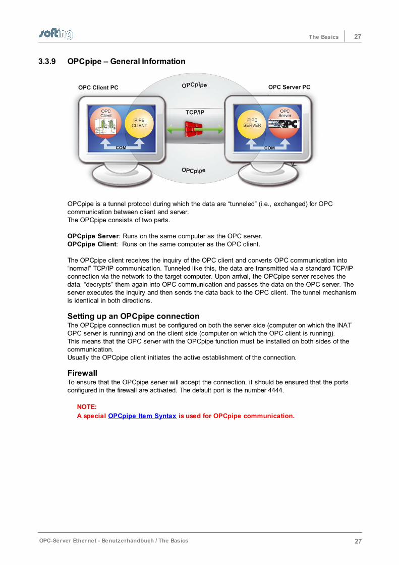
OPCpipe is a tunnel protocol during which the data are “tunneled” (i.e., exchanged) for OPCcommunication between client and server. The OPCpipe consists of two parts.
OPCpipe Server: Runs on the same computer as the OPC server. OPCpipe Client: Runs on the same computer as the OPC client.
The OPCpipe client receives the inquiry of the OPC client and converts OPC communication into“normal” TCP/IP communication. Tunneled like this, the data are transmitted via a standard TCP/IPconnection via the network to the target computer. Upon arrival, the OPCpipe server receives thedata, “decrypts” them again into OPC communication and passes the data on the OPC server. Theserver executes the inquiry and then sends the data back to the OPC client. The tunnel mechanismis identical in both directions.
Setting up an OPCpipe connection The OPCpipe connection must be configured on both the server side (computer on which the INATOPC server is running) and on the client side (computer on which the OPC client is running). This means that the OPC server with the OPCpipe function must be installed on both sides of thecommunication.Usually the OPCpipe client initiates the active establishment of the connection.
FirewallTo ensure that the OPCpipe server will accept the connection, it should be ensured that the portsconfigured in the firewall are activated. The default port is the number 4444.
NOTE:
A special OPCpipe Item Syntax is used for OPCpipe communication.

Operation and configuration
Chapter 4
29Operation and configuration
OPC-Server Ethernet - Benutzerhandbuch / Operation and configuration 29
4 Operation and configuration
This chapter describes the following subjects:
How To ProceedLicensingTool Bar ScreensConnection (Access Path)ConfigurationDialog ScreensMenuTroubleshooting
30 Operation and configuration
30 OPC-Server Ethernet - Benutzerhandbuch / Operation and configuration
4.1 How To Proceed
Parameterization of the OPC server is very simple and takes only a few steps. Thefollowing steps must be performed for OPC communication.
OPC server configurationA connection is set up with NetCon OPC on the OPC server for each piece of hardwarefrom which data are to be read or to which data are to be written. The connectiondefines the access path to the hardware (i.e., the channel between the twocommunication partners). All parameters that are required for the communicationbetween OPC server and the hardware are defined here. The protocols that supportthe communication partners (i.e., S7 protocol and RFC1006) are selected here. Acertain piece of hardware is specified via the target addresses (e.g., IP address andport numbers, or MAC address and TSAP). You can also select whether this connectionis always to be write accessed or not.Set up new access path
Connecting the OPC client and the OPC serverBefore OPC server and OPC client can exchange data with each other, an access path must beestablished between the two. The OPC client that uses the “Connect” function to connect itself withthe server always takes the initiative. The access rights are set via the DCOM settings. See also DCOM settings.
Configuring the OPC clientOn the OPC client, the data points are either selected via tag browsing or entered viaa name. The data points address the hardware via the Item syntax. Addressing can beeither absolute or symbolic. Access path, name and item name are specified foraddressing. The access path name corresponds to the connection name (see OPCserver configuration). With absolute addressing, the protocol-specific item syntax must be adhered to. See Item-Syntax.With icon addressing, the icon file on the OPC server is used.The icons can either be entered manually (see Process server icons ), or imported viaicons. See S7 icon import, Modbus icon import und AB ControlLogiX icons.The icon item names that are defined are then indicated automatically (prerequisite:OPC client supports Alias Browsing).
OPC test clientThe OPC Client that was installed together with the OPC server can be used for initialtesting. Since this client is very easy to handle, you will be able to read out first datapoints immediately.See OPC Client.
DiagnosticsThe Online diagnosis is available for the diagnosis of the connections (access paths).
LoggerAn external Logger is available to record the events which occur on the OPC server.
Server trayA Server Tray is available to start and stop the OPC server and to start the NetCon OPC interface.
See also Overview and Accessories.
31Operation and configuration
OPC-Server Ethernet - Benutzerhandbuch / Operation and configuration 31
4.2 Licensing
A license is required to ensure continuous operation of the OPC server. Without a valid license, the server will run 72 hours and then stop running. There are two types of licenses.
Via a hardware dongle. The order number on the dongle and the type listed under Help - Versions- Server Type sollteshould agree, whereby the last digit of the order number of software anddongle is different. The function can be checked in the License overview dialog screen.Via a software activation code. The server indicates a request code which is sent to SoftingIndustrial Networks GmbH. We then supply an activation code which releases the server. Theprocedure is described in the chapters License overview and License entry.
The server tray monitors the server function cyclically. The license status is indicated in the icon ofthe server tray. The chapter entitled Server tray contains additional information.
Please adhere to the License conditions.

32 Operation and configuration
32 OPC-Server Ethernet - Benutzerhandbuch / Operation and configuration
4.3 Tool Bar
The tool bar is located under Menu. It gives you quick access to frequently used functions.
A tool tip indicates the function when you move the mouse to an icon and stop there.
33Operation and configuration
OPC-Server Ethernet - Benutzerhandbuch / Operation and configuration 33
4.4 Screens
The program essentially consists of the following main screens:
Online diagnosisAccess path listLoggerConfiguration
Additional functions that are indicated in the dialogs are described in the chapters entitled Configuration and Dialogs.
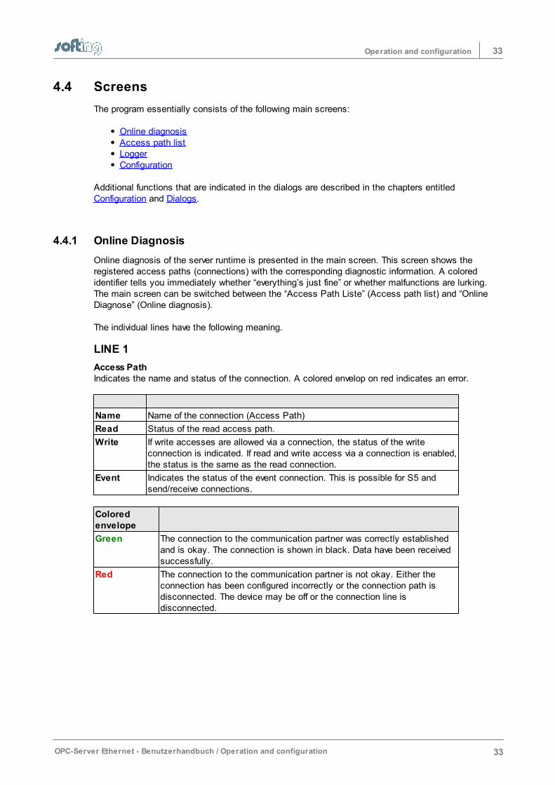
4.4.1 Online Diagnosis
Online diagnosis of the server runtime is presented in the main screen. This screen shows theregistered access paths (connections) with the corresponding diagnostic information. A coloredidentifier tells you immediately whether “everything’s just fine” or whether malfunctions are lurking. The main screen can be switched between the “Access Path Liste” (Access path list) and “OnlineDiagnose” (Online diagnosis).
The individual lines have the following meaning.
LINE 1
Access PathIndicates the name and status of the connection. A colored envelop on red indicates an error.
Name Name of the connection (Access Path)
Read Status of the read access path.
Write If write accesses are allowed via a connection, the status of the writeconnection is indicated. If read and write access via a connection is enabled,the status is the same as the read connection.
Event Indicates the status of the event connection. This is possible for S5 andsend/receive connections.
Coloredenvelope
Green The connection to the communication partner was correctly establishedand is okay. The connection is shown in black. Data have been receivedsuccessfully.
Red The connection to the communication partner is not okay. Either theconnection has been configured incorrectly or the connection path isdisconnected. The device may be off or the connection line isdisconnected.
34 Operation and configuration
34 OPC-Server Ethernet - Benutzerhandbuch / Operation and configuration
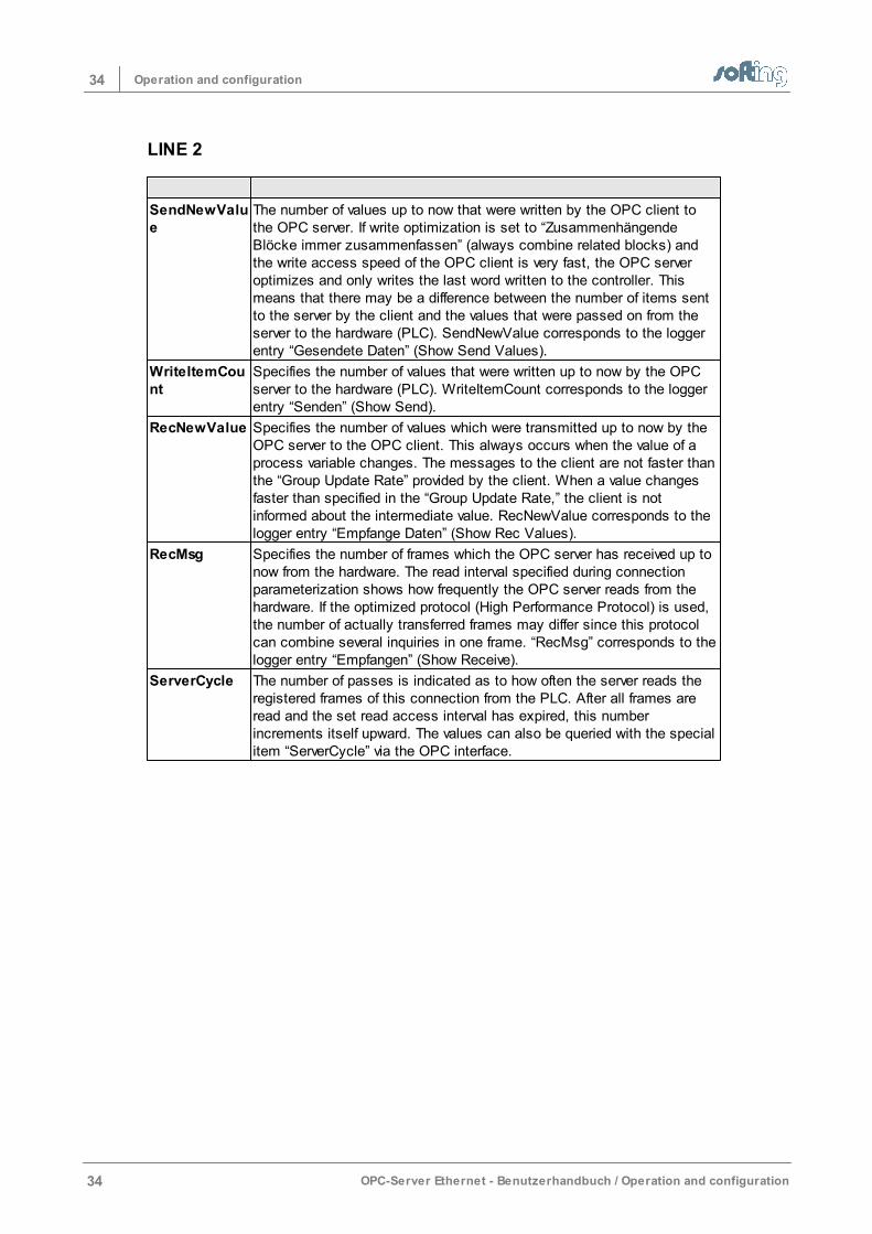
LINE 2
SendNewValue
The number of values up to now that were written by the OPC client tothe OPC server. If write optimization is set to “ZusammenhängendeBlöcke immer zusammenfassen” (always combine related blocks) andthe write access speed of the OPC client is very fast, the OPC serveroptimizes and only writes the last word written to the controller. Thismeans that there may be a difference between the number of items sentto the server by the client and the values that were passed on from theserver to the hardware (PLC). SendNewValue corresponds to the loggerentry “Gesendete Daten” (Show Send Values).
WriteItemCount
Specifies the number of values that were written up to now by the OPCserver to the hardware (PLC). WriteItemCount corresponds to the loggerentry “Senden” (Show Send).
RecNewValue Specifies the number of values which were transmitted up to now by theOPC server to the OPC client. This always occurs when the value of aprocess variable changes. The messages to the client are not faster thanthe “Group Update Rate” provided by the client. When a value changesfaster than specified in the “Group Update Rate,” the client is notinformed about the intermediate value. RecNewValue corresponds to thelogger entry “Empfange Daten” (Show Rec Values).
RecMsg Specifies the number of frames which the OPC server has received up tonow from the hardware. The read interval specified during connectionparameterization shows how frequently the OPC server reads from thehardware. If the optimized protocol (High Performance Protocol) is used,the number of actually transferred frames may differ since this protocolcan combine several inquiries in one frame. “RecMsg” corresponds to thelogger entry “Empfangen” (Show Receive).
ServerCycle The number of passes is indicated as to how often the server reads theregistered frames of this connection from the PLC. After all frames areread and the set read access interval has expired, this numberincrements itself upward. The values can also be queried with the specialitem “ServerCycle” via the OPC interface.
35Operation and configuration
OPC-Server Ethernet - Benutzerhandbuch / Operation and configuration 35
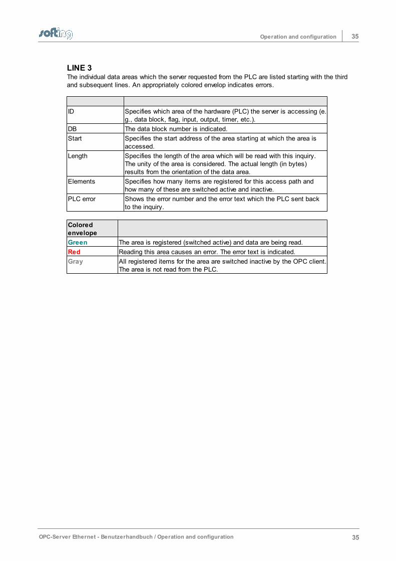
LINE 3The individual data areas which the server requested from the PLC are listed starting with the thirdand subsequent lines. An appropriately colored envelop indicates errors.
ID Specifies which area of the hardware (PLC) the server is accessing (e.g., data block, flag, input, output, timer, etc.).
DB The data block number is indicated.
Start Specifies the start address of the area starting at which the area isaccessed.
Length Specifies the length of the area which will be read with this inquiry.The unity of the area is considered. The actual length (in bytes)results from the orientation of the data area.
Elements Specifies how many items are registered for this access path andhow many of these are switched active and inactive.
PLC error Shows the error number and the error text which the PLC sent backto the inquiry.
Coloredenvelope
Green The area is registered (switched active) and data are being read.
Red Reading this area causes an error. The error text is indicated.
Gray All registered items for the area are switched inactive by the OPC client.The area is not read from the PLC.
36 Operation and configuration
36 OPC-Server Ethernet - Benutzerhandbuch / Operation and configuration
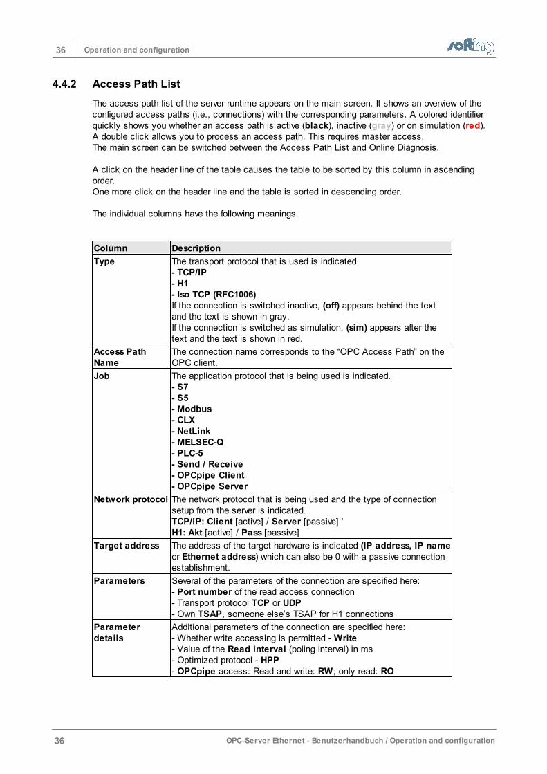
4.4.2 Access Path List
The access path list of the server runtime appears on the main screen. It shows an overview of theconfigured access paths (i.e., connections) with the corresponding parameters. A colored identifierquickly shows you whether an access path is active (black), inactive (gray) or on simulation (red).A double click allows you to process an access path. This requires master access.The main screen can be switched between the Access Path List and Online Diagnosis.
A click on the header line of the table causes the table to be sorted by this column in ascendingorder. One more click on the header line and the table is sorted in descending order.
The individual columns have the following meanings.
Column Description
Type The transport protocol that is used is indicated. - TCP/IP- H1- Iso TCP (RFC1006)If the connection is switched inactive, (off) appears behind the textand the text is shown in gray. If the connection is switched as simulation, (sim) appears after thetext and the text is shown in red.
Access PathName
The connection name corresponds to the “OPC Access Path” on theOPC client.
Job The application protocol that is being used is indicated.- S7- S5- Modbus- CLX- NetLink- MELSEC-Q- PLC-5- Send / Receive- OPCpipe Client- OPCpipe Server
Network protocol The network protocol that is being used and the type of connectionsetup from the server is indicated. TCP/IP: Client [active] / Server [passive] 'H1: Akt [active] / Pass [passive]
Target address The address of the target hardware is indicated (IP address, IP nameor Ethernet address) which can also be 0 with a passive connectionestablishment.
Parameters Several of the parameters of the connection are specified here:- Port number of the read access connection- Transport protocol TCP or UDP- Own TSAP, someone else’s TSAP for H1 connections
Parameterdetails
Additional parameters of the connection are specified here:- Whether write accessing is permitted - Write- Value of the Read interval (poling interval) in ms- Optimized protocol - HPP- OPCpipe access: Read and write: RW; only read: RO
37Operation and configuration
OPC-Server Ethernet - Benutzerhandbuch / Operation and configuration 37
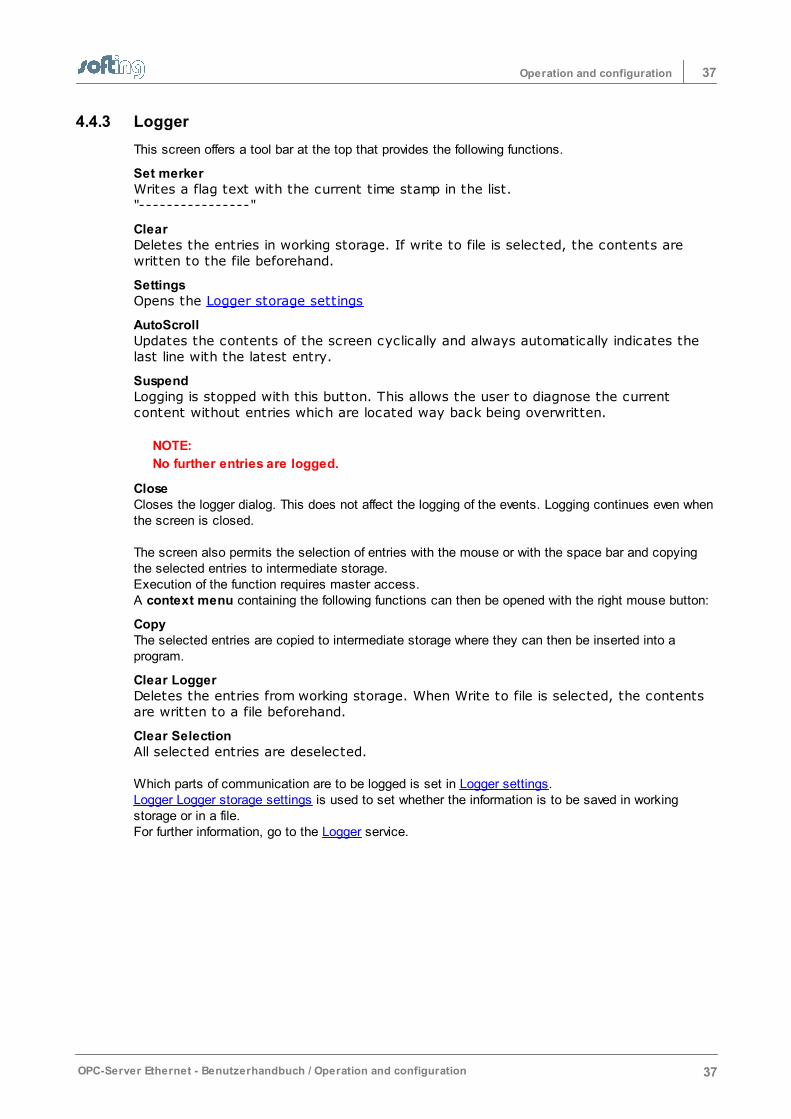
4.4.3 Logger
This screen offers a tool bar at the top that provides the following functions.
Set merkerWrites a flag text with the current time stamp in the list."----------------"
ClearDeletes the entries in working storage. If write to file is selected, the contents arewritten to the file beforehand.
SettingsOpens the Logger storage settings
AutoScrollUpdates the contents of the screen cyclically and always automatically indicates thelast line with the latest entry.
SuspendLogging is stopped with this button. This allows the user to diagnose the currentcontent without entries which are located way back being overwritten.
NOTE:
No further entries are logged.
CloseCloses the logger dialog. This does not affect the logging of the events. Logging continues even whenthe screen is closed.
The screen also permits the selection of entries with the mouse or with the space bar and copyingthe selected entries to intermediate storage. Execution of the function requires master access.A context menu containing the following functions can then be opened with the right mouse button:
CopyThe selected entries are copied to intermediate storage where they can then be inserted into aprogram.
Clear LoggerDeletes the entries from working storage. When Write to file is selected, the contentsare written to a file beforehand.
Clear SelectionAll selected entries are deselected.
Which parts of communication are to be logged is set in Logger settings. Logger Logger storage settings is used to set whether the information is to be saved in workingstorage or in a file. For further information, go to the Logger service.
38 Operation and configuration
38 OPC-Server Ethernet - Benutzerhandbuch / Operation and configuration
4.4.4 Configuration
The Configuration screen shows if NetCon OPC is started via Start - (All) Programs -INAT - NetCon OPC - NetCon OPC. If NetCon OPC is started via the server tray, theOnline-Diagnosis is indicated directly and not this screen.
NetCon OPC is needed for the configuration of the INAT OPC server. It is used to makebasic settings on the server, set up and diagnose connections and indicate thecontents of the logger. Connection of NetCon OPC to ServerRuntime can be done inone of the following ways.
Configuration via TCP/IPA socket connection to the server is established via TCP/IP. This can be a connectionto the server that is running on the same PC or a server that is connected via theEthernet network. The entires are transmitted directly to the server and stored there.This method permits the server to be configured from any point in the TCP/IP network.
Configuration via H1The installation of the H1 protocol driver is required for configuration via H1. An H1connection is established to the server that is to be configured. This can be aconnection to a server on which another PC is running and is connected via theEthernet network. A connection to a server which is running on the same PC is notpossible. The entries are transmitted directly to the stations and stored there. Thismethod allows the stations to be configured from any point in the H1 network.
Configuration offlineOffline configuration is not provided for the server.
Language selection (buttons with flags)Buttons with flags can be used to switch to another language. After a NetCon OPCnew start, all texts can then be indicated in the desired language. The texts that thelogger indicates are not changed by this.
39Operation and configuration
OPC-Server Ethernet - Benutzerhandbuch / Operation and configuration 39
4.5 Connection (Access Path)
This chapter describes the dialogs that are used for handling the connections (access paths) of theserver.Additional dialog screens are described in the chapters Dialogs and Configuration.
The following dialogs are described here.
New Connection (Access Path)Network protocolOPC Server Connection
IP AddressPortTSAPTSAP for S7 connectionsRouting TSAPsEvents from the PLCModbus Protocol SettingsCLX Protocol SettingsMelsec-Q Protocol Settings
Edit ConnectionServer SettingsNetwork TCP/IP parametersOPCpipe Parameters
Copy Connection Delete ConnectionSwitching a Connection Inactive
4.5.1 New Connection (Access Path)
OPC server – new connectionAt least one connection on the OPC server must be set up for every piece of hardware which is to beaccessed (i.e., with which the server is to communicate). The connection defines the access path tothe hardware (i.e., the channel between the two communication stations – the access path). Thenumber of TCP/IP connections is NOT restricted. The number of H1 connections is restricted to 64although this can be increased to 200 with the registry entry "200H1Connections. reg."Go to the menu Connection - New Access Path to set up a new connection. This dialog offers thefollowing possible entries.
Connection NameThe name of the connection can be selected as desired except that only letters and numbers shouldbe used. Special characters and blanks are not permitted because they may cause the connectionto function incorrectly or to not be able to be addressed via OPC. The connection name which isused here will also be specified later when the access path is specified for the OPC client.
Connection typeThis is where the type of connection is selected, whether a new PLC connection or a OPCpipeconnection is to be set up. The type OPCpipe Server or OPCpipe Client is also selected under the OPCpipe type. Afterconfirmation with OK, the Network protocol dialog screen opens.
40 Operation and configuration
40 OPC-Server Ethernet - Benutzerhandbuch / Operation and configuration
4.5.2 Network Protocol
Transport protocolThis is where the transport protocol is selected that is to handle communication on the Ethernetnetwork.
TCP/IP is included in the operating systemor
H1 which reguires an H1 protocol driver which has to be installed for this purpose. If the driveris not installed, H1 will not be available. TCP/IP should be selected for RFC1006 (ISO on TCP) communication.
Application protocolThe application protocol is selected here.
Application protocol PLC
Send/Receive Communication to other PLCs or devices which cannot handleany of the protocols listed below. User data is transmitted withoutprotocol information.
S5 AP Communication to Siemens S5 CPs or INAT echolink,echocollect or echochange.
S7 S7 protocol to Siemens S7-400, S7-300 or S7-200 automationsystems, INAT echolink and echocollect
Modbus TCP Communication with PLCs or devices which can handle theModbus TCP protocol such as Wago, Beckhoff, GroupSchneider, Modicon, and so on.
Netlink IBHLink, NetLink
CLX - Ethernet/IP Allen Bradley Control LogiX, Compact LogiX
Slc/Plc5 Allen Bradley PLC-5 und SLC
Melsec-Q Mitsubishi Melsec-Q
OKConfirmation with OK opens the screen OPC server connection.
41Operation and configuration
OPC-Server Ethernet - Benutzerhandbuch / Operation and configuration 41
4.5.3 OPC Server Connection
General
Enable cyclic read access and read intervalCyclic read access is activated as the standard. The server reads the values of thevariables from the hardware via a fetch active connection at a certain time interval. Itcan be specified in Leseintervall [in ms] (read interval) the time intervals at which theserver is to send a read request to the PLC. The setting “0” means that it should beread as soon as possible. If "Zyklisches Lesen einschalten" (Enable cyclic read) isselected, read access is performed once when the client requests and no longercyclically. However, this is only necessary in special cases and requires a preciseknowledge of the communication.
Write to the PLC permitted (Write Allowed)Here you specify whether write access to the PLC is to be possible via this connectionand a write connection is to be established to the hardware. You can always disablewrite accessing via a connection if you only want to use read accesses or if you wantto be sure that no values on the PLC are to be changed. When write accessing thePLC via a Write aktiv¬Verbindung (Write activeConnection) (or a Send Direkt-Verbindung bei Send/Receive (Send Direct Connection for Send/Receive)), certainpoints of the PLC are written with values (each write access is preceded by a readaccess).
A connection for Read and Write accessWith the S7, NetLink and Send/Receive protocols, read and write accesses via aconnection are possible and activated as the default setting. Only a port for TCP/IP oronly a TSAP for RFC1006 must be specified for the read and write access. The S5protocol is an exception: Read and write accesses via one connection are NOTpossible. One connection is required for read accesses and another connection isrequired for write accesses. A port number (or TSAP) is required for read accesses anda port number (or TSAP) is required for write accesses. More recent INAT S5-TCP/IPcards, echolink and echocollect permit read and write accesses via one connection.
Use Read (Events)Read stands for receiving for Send/Receive connections.Events from the PLC are only possible with S5 connections. See also Events from the PLC.
PLC protocol settingsThe button opens a further dialog screen in which specific parameters can be set forthe following protocols:Modbus protocol settingsCLX protocol settingsMelsec-Q protocol settings
TCP/IP communication
Destination: IP address or nameThis is where the IP address of the target station (IP address of the PLC) or the DNSname of the target station is entered. If the computer was configured for DNS and if aDNS server is available on the network, the symbolic name of the target station canalso be entered. For how an IP address is set up, see IP address.
No Header"No header" is used for connections to stations which only support the pure TCP/IPprotocol. In this case, the application program is responsible for monitoring on bothsides.
42 Operation and configuration
42 OPC-Server Ethernet - Benutzerhandbuch / Operation and configuration
PLC Header"PLC header" is used for communication to the INAT components (S5-TCP/IP, echolink,echocollect)
RFC1006When RFC1006 is activated, H1 frames are packed into a TCP/IP frame fortransportation. The "ISO on TCP (RFC1006)" button is clicked for the TSAP settings.
Local TSAP, remote TSAPTSAPs (Transport Service Access Points) are addresses which are used within thetransport layer to address applications. TSAPs are required for RFC1006 connections.To set up a connection, both the local TSAP and the TSAP of the communicationpartner must be specified. The following must be adhered to.
NOTE:
The TSAPs must coincide crosswise before the connection can be established!
The local TSAP of the one system must correspond to the remote TSAP of the othersystem.
For further information on the TSAPsTSAPs for S7 connections
Routing TSAPsRouting is the capability of the OPC server to also address controllers even if they areoutside the subnet boundaries. This requires special routing TSAPs. For further information on routing TSAPs
Port for read accesses, port for write accessesPort numbers are addresses which are used within the transport layer to addressapplications. Port numbers are required for TCP connections. The port is parallel to theTSAPs for RFC1006 and H1 connections. The port number is a 16-bit number from 1 to65535. Keep the following in mind when you set up the connection.
NOTE:
The port must be identical on both sides of the connection before you can set up theconnection.
Read, write and event ports should be addressed differently. Port numbers 1 to 1023should not be used since these are already being used by well-known services (so-called well-known ports). For further information on ports
AcksWhen you select "Acks", connection monitoring of the socket libraries is enabled. Ifthis option is disabled, the connection is considered as concluded after theKeepAliveTime but the communication partner is not told. We recommend enabling thisoption.
Life Data AcksWhen you select "Life Data Acks", user data telegrams are transmitted with no datacontent in order to keep a connection alive which is not used cyclically. Bothcommunication partners must support this functionality. With communication to S7PLCs, we recommend switching this option off.
Type active (client) / passive (server)Here you specify whether the own station actively initiates the connection setup orpassively expects the connection setup by the other station. You may not enter thesame value on both sides of the connection. Usually, the PC with OPC server isparameterized as active. This is also used here as the default value.
43Operation and configuration
OPC-Server Ethernet - Benutzerhandbuch / Operation and configuration 43
TCP/UDP protocolThe TCP is a secure protocol with checksum and confirmation. UDP is not secure and is handled viadatagram services. The TCP protocol should be selected for normal data transmission.
Osi/H1 communication
Destionation station: Ethernet address, card (adapter)The Ethernet address of the target station is entered here. The target address consists of 6 bytes. Inaddition, the number of the Ethernet card is specified which is connected to the ISO (H1) network.
Local TSAP, remote TSAPTSAPs (Transport Service Access Points) are addresses which are used within the transport layer toaddress applications. Both the local TSAP and the TSAP of the communication partner are specifiedto establish the connection. The following must be kept in mind.
NOTE:
The TSAPs must correspond crosswise before a connection can be set up!
The local TSAP of a system must correspond to the remote TSAP of the other system.
For further information on the TSAPsTSAPs for S7 connections
Connection setup type active/passiveThis is where you specify whether the own station actively initiates the connection setup or passivelyexpects the connection to be set up by the other station. The same value may not be entered forboth sides. Usually the PC is parameterized as active. This is also the default value here.
PriorityThe line priority can be from 0 (highest priority) to 4 (lowest priority). 0 and 1 are the so-calledexpress priorities while 2 and 3 are the normal priorities. “Prio 4” is only seldom used because theconnection is set up again for every send job. On the other hand, when seldom used, it requires lessof the network than the other priorities because the line is not monitored (it is set up again after everysend job). Remember though that, with the express priorities, the transmission is not faster than withthe normal priorities. With some controllers, the data are transferred via interrupt to working storageeven when priority 0 is used. That can result in faster total data transmission. With priority 0 and 1,the data cannot be longer than 16 bytes. Usually “Prio 3” is entered here.
ProtocolSpecifies whether the frames of this connection are sent to everyone (broadcast), whether a certaingroup of stations is to be reached (multi-cast), whether a secure connection will be used (normal) orwhether the data are to be transmitted unsecured (datagram). “Normal” is usually set here.
Expanded settings
Read optimizationReading from the controller can be optimized here. If several variables are requestedwhich are located in the same operand area (e.g., in a data block or in the flag area),the complete area is read from the first variable to the last variable without readoptimization. Gaps between the individual block areas are also read no matter howlarge these gaps are. The maximum size of the gaps (in bytes) between the requestedindividual items within a data block without a new block being created is entered. Ifthe gap equals the specified value, a new block is created.
Use High Performance ProtocolWhen the optimized protocol is activated, accesses to variables which are NOT in thesame operand area (e.g., DB5.W3 + MW1 + T2, etc.) are converted internally on theserver to a single field access to the target device. This reduces the number of datapackets that are transported via the network. The share of user data is greater, thedata packets are better utilized and the network load is reduced. Thus the serverworks particularly quickly in this mode.
44 Operation and configuration
44 OPC-Server Ethernet - Benutzerhandbuch / Operation and configuration
Access over OPCpipe allowedWith this option, the access of an OPCpipe server permits connection to the connection configuredhere. This makes it possible to access a remote PC via this connection to the PLC. OPCpipeconnections can be used to circumvent the time-consuming DCOM configuration and to avoidenabling the NetBIOS ports in the firewall. Only one, freely selectable port in the firewall needs to beenabled which is then specified for the OPCpipe connection.
Allow Write over OPCpipeThe write access is turned on or off with this option.
Simulate connection and dataIf a real PLC is not available for test purposes, the option can be enabled to simulate a PLC. To theOPC client it looks as if a device were connected and the connection was working. Write accessesare also possible on the registered data points.
4.5.3.1 IP Address
The basicsIn order to establish communication between two technical devices, each of the devices must beable to send data to the other device. To ensure that these data arrive at the right place on the otherstation, this station must be named (i.e., addressed) unambiguously. In IP networks this is donewith an IP address. An OPC server can address a PLC directly via its IP address (e.g., 192.168.1.20). A PLC can alsobe addressed via its name. This means that the name of the PLC must be stored with the applicableIP address and the domain server must be entered in the TCP/IP of the server. The server asks for adomain name (e.g., “PLC1”, the IP address for a name server) and then addresses the PLC directlyvia its IP address “192.168.1.20.”
IP addressEvery IP data package begins with an information area for transportation through the IP layer – the IPheader. This header also contains two fields in which the IP addresses of both the sender and thereceiver are entered before the data package is sent. Relaying occurs in layer 3 of the OSI model –the relaying layer.
Setup
IPV4The IPv4 addresses predominantly used since the introduction of version 4 of the Internet protocolconsist of 32 bits (i.e., 4 octets – bytes). This means that 232 (i.e., 4,294,967,296) addresses canbe represented. In dotted decimal notation, the 4 octets are written in decimal presentation as fourwhole numbers separated from each other by dots from 0 to 255.
Example: 192.168.1.20.
IPV6 – new version with larger address areaDue to the quickly increasing need for IP addresses, the day is coming when the usable addressarea of IPv4 will be exhausted. The IANA address pool was used up on February 3, 2011. IPv6 was primarily developed for that
reason. It uses 128 bits to store addresses which means that 2128 = 25616
(= 340.282.366.920.938.463.463.374.607.431.768.211.456 ˜ 3,4 · 1038) addresses can berepresented. This number is sufficient to provide at least 665.570.793.348.866.944
(= 6,65 · 1017) IP addresses for every square millimeter of the earth’s surface.
Since the decimal representation ddd.ddd.ddd.ddd.ddd.ddd.ddd.ddd.ddd.ddd.ddd.ddd.ddd.ddd.ddd.ddd would be confusing and difficult to handle, we usually represent IPv6 addresses as hexadecimal

45Operation and configuration
OPC-Server Ethernet - Benutzerhandbuch / Operation and configuration 45
numbers. To further simplify this representation, two octets each of the address are combined andpresented in groups separated by colons. XXXX:XXXX:XXXX:XXXX: XXXX:XXXX:XXXX:XXXX.
Example: 2001:0db8:85a3:0000:0000:8a2e:0370:7344
To further shorten the presentation, zeros can be left off at the beginning of a block.
A sequence of blocks which only consist of zeros is replaced by :: but only once per IPV6 address.
Example: 2001:db8:85a3::8a2e:370:7344
When IPV6 is used, usually names are specified instead of the IP addresses.
4.5.3.2 Port
Port numbers are addresses which are used within the transport layer to address applications. Portnumbers are required for TCP/UPD connections.The port number is a 16-bit number from 0 to 65535. Certain applications use port numbers which are permanently assigned to them by the IANA and aregeneral knowledge. They are usually between 0 and 1023 and are known as “well known” ports. Theregistered ports are located between ports 1024 and 49151. If needed, makers of applications canhave ports registered for their own protocols. The remaining ports (49152 to 65535) are the so-called “Dynamic” and/or PrivatePorts. The use of these ports is variable since they are not registered and therefore do not belong toany application.
4.5.3.3 TSAP
TSAP = Transport Service Access Point ISO (H1) uses so-called TSAPs in the transport layer to address the applications.These connection points are required for both ISO (H1) connections and RFC1006connections.
Parameter for ISO (H1) Connections Parameter for RFC1006 Connections
Station A Station B Station A Station B
Local TSAP A Remote TSAP B MAC address A
Local TSAP B Remote TSAP A MAC address B
Local TSAP A Remote TSAP B IP address A
Local TSAP B Remote TSAP A IP address B
Before a connection can be established, the TSAPs must correspond crosswise (i.e.,the “local TSAP” of communication partner A must correspond to the “remote TSAP” ofcommunication partner B). In contrast, the “remote TSAP” of station A mustcorrespond to the “local TSAP” of station B. Local TSAP (station A) = remote TSAP (station B) Remote TSAP (station A) = local TSAP (station B)
This requirement is easy to adhere to if you select identical values for “local TSAP”and “remote TSAP.” Local TSAP and remote TSAP may be identical. If several connections are set up between 2 stations, the TSAPs of the individualconnections must be different. The combination of TSAP + MAC address (or IP address) must be unambiguous so thata connection can be precisely specified.
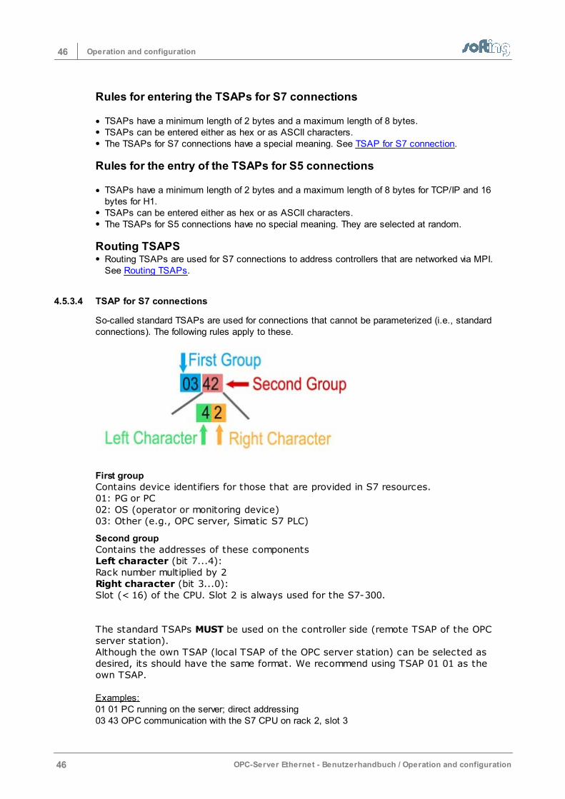
46 Operation and configuration
46 OPC-Server Ethernet - Benutzerhandbuch / Operation and configuration
Rules for entering the TSAPs for S7 connections
TSAPs have a minimum length of 2 bytes and a maximum length of 8 bytes.TSAPs can be entered either as hex or as ASCII characters. The TSAPs for S7 connections have a special meaning. See TSAP for S7 connection.
Rules for the entry of the TSAPs for S5 connections
TSAPs have a minimum length of 2 bytes and a maximum length of 8 bytes for TCP/IP and 16bytes for H1.TSAPs can be entered either as hex or as ASCII characters. The TSAPs for S5 connections have no special meaning. They are selected at random.
Routing TSAPSRouting TSAPs are used for S7 connections to address controllers that are networked via MPI.See Routing TSAPs.
4.5.3.4 TSAP for S7 connections
So-called standard TSAPs are used for connections that cannot be parameterized (i.e., standardconnections). The following rules apply to these.
First groupContains device identifiers for those that are provided in S7 resources. 01: PG or PC02: OS (operator or monitoring device)03: Other (e.g., OPC server, Simatic S7 PLC)
Second groupContains the addresses of these componentsLeft character (bit 7...4):Rack number multiplied by 2Right character (bit 3...0):Slot (< 16) of the CPU. Slot 2 is always used for the S7-300.
The standard TSAPs MUST be used on the controller side (remote TSAP of the OPCserver station).Although the own TSAP (local TSAP of the OPC server station) can be selected asdesired, its should have the same format. We recommend using TSAP 01 01 as theown TSAP.
Examples:01 01 PC running on the server; direct addressing 03 43 OPC communication with the S7 CPU on rack 2, slot 3
47Operation and configuration
OPC-Server Ethernet - Benutzerhandbuch / Operation and configuration 47
03 02 OPC communication with the S7 CPU on rack 0, slot 203 2E OPC communication with the S7-CPU on rack 1, slot 14
NOTE:
The binary standard TSAPs are entered in the HEX window (left).
4.5.3.5 Routing TSAPs
Routing makes it possible for the OPC server controller to communicate over subnetboundaries. OPC communication is possible with all stations which can be reached overnetwork crossings. It does not matter how many network crossings there are or howmany networks are located between the Ethernet network (in which the OPC serverstation is located) and the target network. A connection only has to be parameterizedon the OPC side for the fetch/write communication. It is not necessary to set up aconnection on the S7. Establishment of the connection path requires that informationon the target network and the target station be known. The following settings must bemade for routing.
S7 routing – general information
The first device between network and MPI is echolink. When an echolink is used to provide the connection between Industrial Ethernet and the subnetwork,this box should be activated. In this case, information on the routing PLC is necessary.
Routing PLCThe routing PLC is the S7 controller that is connected with the echolink via MPI andprovides the first transition from Industrial Ethernet to MPI. The MPI address of therouting module is entered here (MPI address of the CPU or the CP).
Destination PLCSettings for the target PLC are made here (i.e., the controller from which the valueswere read or to which the values are to be written).
S7 subnet IDEach subnet on the S7 receives a subnet ID which is automatically generated by Step7. The subnet ID of the target network must be specified here. For example, the S7subnet ID can be determined as shown below. • Open the “NetPro” screen in the Step 7 program. • With the right mouse button click the network and the object properties.
MPI/PROFIBUS AddressIf this is an MPI network, the MPI address of the PLC is entered here. If this is aPROFIBUS network, the PROFIBUS address is entered here.
Slot of the CPUThe slot number of the CPU is entered here.
ServiceThe “3” service is provided for OPC connections.
COM PortThe COM port of the echolink device via which echolink is connected with the MPIinterface of the S7 PLC is selected here.
NOTE:
Some CPs have their own MPI address. This MPI address is automatically determinedand assigned by the CPU. If such a CP is being used, you must be absolutely sure that
48 Operation and configuration
48 OPC-Server Ethernet - Benutzerhandbuch / Operation and configuration
the MPI address of the CP is used and NOT the MPI address of the CPU.
Determining the MPI address of the routing PLC (Back plane MPI CP port or MPI address ofthe CPU)The MPI address of the routing PLC is determined in “NetPro” by highlighting thestation and then selecting "Object properties" with the right mouse button. If a CP-MPI address appears here in addition to a CPU-MPI address, the MPI address ofthe CP should be used.
Another way is to highlight the CP in the hardware configuration, and then select"Objekteigenschaften" (Object properties) with the right mouse button. The MPIaddress to be used is then indicated under "Back plane connection".
Generate TSAPsAfter all settings have been made, press the “TSAPs erstellen” (Create TSAPs) button.The TSAPs are then created and automatically entered in the two dialog screens.
4.5.3.6 Events from the PLC
In addition to cyclic read (fetch active) and write (write active) accesses, the serveralso supports events from the PLC. A channel is reserved which is used to deliver thespontaneous data from the PLC. The event channel is its own connection. Accordingly,a separate “port for events” (for TCP/IP connections) or a separate (remote) “TSAPfor events” (for H1 and/or RFC1006 connections) is defined.
The port numbers/TSAPs for read, write accesses and events may never be the same!
Events from the PLC are possible with the following connections. S5Send / Receive
Active / passive connection establishment for eventsThe type of connection establishment (active or passive) can be set for the “eventsfrom the PLC” mode can be set independently from the connection establishment forread and write connections.
In the example below, the connection establishment for read and write accesses isactive while the connection establishment for “events” is passive Reason:Some CPs can only be parameterized for send jobs actively (required for „events fromthe PLC).
4.5.3.7 Modbus Protocol Settings
This dialog lets you change special parameters of a connection to Modbus controllers.
Description Default
Slave address The slave address that is set is transmitted in the Modbusframe.
1
Start address 0 The start address is transmitted as specified in theframe.
Yes
Start address 1 Some Modbus devices expect a start address in theframe which is 1 less than the entered address. The firstaddress is 1.
No
49Operation and configuration
OPC-Server Ethernet - Benutzerhandbuch / Operation and configuration 49
Use Byte Swab Switch bytes within a word Off
Use Word Swab Reverse words within a double word (32 bits) Off
Use Write SingleCoil (05)
The Modbus opcode Write Single Coil 05 is used for writeaccesses instead of Write Multiple Coils 15.
Off
Use Write SingleRegister (06)
The Modbus opcode Write Single Register 06 is used forwrite accesses instead of Write Multiple Register 16.
Off
User Item Unit ID The slave address is specified via the item syntax(e.g., Id2.R2). For more information, go to Modbus Item Syntax
1
IO Address isOctal
The start address of certain devices is octal. This meansthat the numbers 8 and 9 are invalid characters. Thisapplies to the inputs and outputs. In addition, J isspecified for inputs and P is specified for outputs in theitem syntax.
Off
4.5.3.8 CLX Protocol Settings
This dialog screen lets you change special parameters of a connection to Allen Bradley ControlLogiXcontrollers.
Connection nameThe name of the connection is indicated here.
CPU slotThe slot of the ControlLogiX CPU is specified here.
Browse filter masksSome PLC programs contain a great many variables. These are created by PLC program codegenerators and are used internally. Not all tags available on the PLC are used by SCADA systems.Usually only a few of these variables are involved. The start of the OPC server and the access of OPC clients to indicate the browsing list can take avery long time if there are many variables. This is particularly true when the Ethernet module of thePLC is not integrated in the CPU.
Setting the browser filter:The CLX browser filters are entered in the input fields Inclusive browser mask and Exclusivebrowser mask. A combination is possible. The inclusive screen is evaluated first followed by theexclusive.
Inclusive browser mask:Only the specified values are shown and available for OPC browsing.
Exclusive browser mask:The specified variables are not shown.
If a mask is blank, it will be ignored.
A mask is a text which consists of one or more entries.
An entry without a dot “.” refers to the variables in “controller tags.” Example: Variable1.
An asterisk “*” can be used at the end of the entry as the placeholder for any character string.Example: Var*This determines all variables which begin with the text “Var.” These would also be: Variable1,variable2, VAR3, variance.
If “program tags” are to be addressed, an entry contains a dot (“.”). The name of the subprogram isspecified in front of the dot. The asterisk “*” can be used as a placeholder at the end. The variable
50 Operation and configuration
50 OPC-Server Ethernet - Benutzerhandbuch / Operation and configuration
name is specified after the dot. The asterisk “*” can also be used behind that. Example: Program:MainProgram.Var*Example: Program:A*.*
A program name without a dot is ignored.
Individual entries are separated by a semicolon (“;”).
Upper case and lower case letters are ignored.
Blanks are not allowed.
Variable names may not contain a dot (“.”), a semicolon (“;”) or an asterisk (“*”). If such charactersare included anyway, a search cannot be made for them.
The maximum number of characters for a filter is 300 characters.
A more detailed example:Var*;Prog*.subvar*All variables in the “Controller Tags” list are determined that begin with the text “Var”. In addition, allvariables in all subprograms that begin with the program name “Prog” are searched for variableswhich begin with “subvar.”
Variables which are filtered out during browsing cannot be addressed via OPC later on. The filtermust be adjusted for that.
4.5.3.9 Melsec-Q Protocol Settings
The dialog permits you to change special parameters of a connection to Mitsubishi Melsec-Qcontrollers.
These parameters must be set when Mitsubishi Net is set up and the hardware supports it.
Description Hex Decimal
DestinationModule
Network address 0x3FF 1023
Monitor Timer Time monitoring during which the answer shouldhave been received.
0x100 256
Networknumber
Network number in the hardware configuration of theprogramming software.
0 0
PLC Number An additional intermediate PLC number. 0xFF 255
PC Number Is only applicable when rights management is setup. Access of the PC can be permitted or prohibitedwith this.
0xFF 255
DestinationStation
The module address of an additional module in aPLC.
0 0
The effects of these values depend on the hardware that is being used.
51Operation and configuration
OPC-Server Ethernet - Benutzerhandbuch / Operation and configuration 51
4.5.4 Edit Connection
Name of the ConnectionThe connection name is indicated and can be changed here.
Connection ActiveIndicates whether the connection is activated. If not, items cannot be registered andconnections to the PLC cannot be established. This makes it possible to briefly shutdown a connection without deleting it and having to enter it again later.
SimulationIndicates whether the connection is marked as simulation. This function can be used to simulateconnections although no communication with the PLC occurs. Items can be registered and writeaccessed. The server administers the data internally. The window frames light up red in this mode. Asimulation connection appears in “red” in the screen Access Path List.
ButtonAdditional parameters can be processed depending on the type of connection.
Server Settings opens the dialog screen OPC Server ConnectionNetwork Parameters opens the dialog screen TCP/IP Connect ParametersOPCpipe settings opens the dialog screen OPCpipe Settings
The number of available options varies depending on the type of connection.
4.5.4.1 Server settings
The button opens the dialog screen OPC Server Connection.
4.5.4.2 Network TCP/IP parameters
This dialog screen makes it possible to change the TCP/IP parameters.
Connection NameThe connection name can be selected as desired. In the “Verbindungsname” (Connection name) fieldall characters are allowed except the dot and the square parentheses. The connection name that isused here MUST also be used later when the Access Path is entered on the OPC client.
Destination IP-AddressThe IP address of the target station (IP address of the PLC) or the DNS name of the target station isentered here. If the computer was configured for DNS and a DNS server is available in the network,the symbolic name of the target station can also be entered. IP Address explains how an IP address is set up.
Destination Port Port numbers are addresses which are used within the transport layer to address applications. TCPconnections need port numbers. The port is a parallel to the TSAPs for RFC1006 and H1connections. The port number is a 16-bit number from 1 to 65535. See the following for moreinformation on setting up the connection
NOTE:
The port must be identical on both sides of the connection otherwise theconnection cannot be established.
For further information on ports
Connection establishment (Type):It is specified here whether the own station is to actively initiate the connection establishment orwhether it passively expects the connection to be established by the target station. The same value
52 Operation and configuration
52 OPC-Server Ethernet - Benutzerhandbuch / Operation and configuration
may not be entered on both sides of the connection.
client (Active) Connection establishment is actively initiated.
Server (Passive) Wait until the target station initiates the establishment of theconnection.
Life Data AcksWhen "Daten-Lebenstelegramme" (Data life frames) is enabled, user data frames with no datacontent (only the header) are transferred to keep a connection alive which is not cyclically used.Both communication partners must support this function. With OPCpipe communication, werecommend enabling this option.
4.5.4.3 OPCpipe Parameters
Connection NameEach connection must have an unambiguous name so that it can be quickly identified later in theconnection overview
OPCpipe recognizes several Security settings.
PasswordThe code word is used for access security while the connection is being established. It istransmitted over the network encrypted.
Connection ActiveAn access path can be switched inactive if it is not supposed to communicate with the PLC. Thismakes it possible to deactivate the connection temporarily without having to delete it and re-enter itagain later.
Write allowedIf this is not set, the connection can only be read accessed.
Memory LimitAn OPCpipe frame can have up to 4 gigabytes. Such large frames are usually not needed. But sinceOPCpipe must provide memory space for such frames, this memory can be limited to prevent a slowdown. The memory limit should be set so that the maximum frame length of an single frame will notbe cut off by this setting.If the runtime of the memory limit is exceeded, the data are thrown out and the communicationpartner is informed.
Use Send AcknowledgeOPCpipe recognizes the acknowledge mode with which the data that were read are confirmed withan acknowledgement. The data that were sent are also acknowledged even if this option is notenabled. This mode slows down communication and should only be used in cases where it must be ensuredthat all received data have actually arrived.This mode can only be used when the target station also supports acknowledgement mode.
4.5.5 Copy connection
A connection can be copied. All parameters (with the exception of the connection’sname) of the highlighted connection are copied. The new connection name should beadjusted before the connection is saved. After it has been saved, the connection isindicated in the Access Path List.
53Operation and configuration
OPC-Server Ethernet - Benutzerhandbuch / Operation and configuration 53
4.5.6 Delete connection
The highlighted connection is deleted. This procedure cannot be reversed!As an alternative to deletion, a connection can also be switched inactive (Switch on/off).You can also select whether the symbols for this connection are to be retained or alsodeleted.
4.5.7 Switching a Connection Inactive
Below are the following ways that a connection can be switched inactive.
Menu Connection > Switch on/off• Highlight the connection and select Switch on/off with the right mouse button.
The text “off” then appears after the type in the connection overview Access Path List.
54 Operation and configuration
54 OPC-Server Ethernet - Benutzerhandbuch / Operation and configuration
4.6 Configuration
This chapter describes the dialog screens that are used to configure the server. Additional dialog screens are described in the chapter entitled Dialog screens and Connection(Access Path).
The following dialog screens are described here.
Server System SettingsLogger SettingsLogger Memory SettingsStation PasswordH1 MAC AddressServer Symbole BearbeitenS7 SymbolimportAB ControlLogiX SymboleModbus SymbolimportVerzeichnis für Konfigurationsdatei
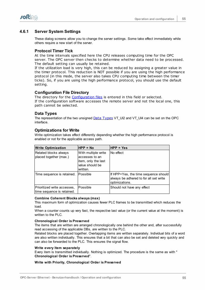
55Operation and configuration
OPC-Server Ethernet - Benutzerhandbuch / Operation and configuration 55
4.6.1 Server System Settings
These dialog screens allow you to change the server settings. Some take effect immediately whileothers require a new start of the server.
Protocol Timer TickAt the time intervals specified here the CPU releases computing time for the OPCserver. The OPC server then checks to determine whether data need to be processed.The default setting can usually be retained. If the utilization load is very high, this can be reduced by assigning a greater value inthe timer protocol. This reduction is NOT possible if you are using the high performanceprotocol (in this mode, the server also takes CPU computing time between the timerticks). So, if you are using the high performance protocol, you should use the defaultsetting.
Configuration File DirectoryThe directory for the Configuration files is entered in this field or selected.If the configuration software accesses the remote server and not the local one, thispath cannot be selected.
Data TypesThe representation of the two unsigned Data Types VT_UI2 and VT_UI4 can be set on the OPCinterface.
Optimizations for WriteWrite optimization takes effect differently depending whether the high performance protocol isenabled or not for the applicable access path.
Write Optimization HPP = No HPP = Yes
Related blocks alwaysplaced together (max.)
With multiple writeaccesses to anitem, only the lastvalue should bewritten.
No effect
Time sequence is retained. Possible If HPP=Yes, the time sequence shouldalways be adhered to for all set writeoptimizations.
Prioritized write accesses,time sequence is retained.
Possible Should not have any effect
Combine Coherent Blocks always (max)This maximum form of optimization causes fewer PLC frames to be transmitted which reduces theload. When a counter counts up very fast, the respective last value (or the current value at the moment) iswritten to the PLC.
Chronological Order is PreservedThe items that are written are arranged chronologically one behind the other and, after successfullyread accessing of the applicable DBs, are written to the PLC. Related blocks are placed together. Overlapping items are written separately. Individual bits of a wordare also written individually. This ensures that a bit that can also be set and deleted very quickly andcan also be forwarded to the PLC. This ensures the signal flow.
Write every Item separatelyEvery item is transmitted individually. Nothing is optimized. The procedure is the same as with "Chronological Order is Preserved".
Write with Priority, Chronological Order is Preserved
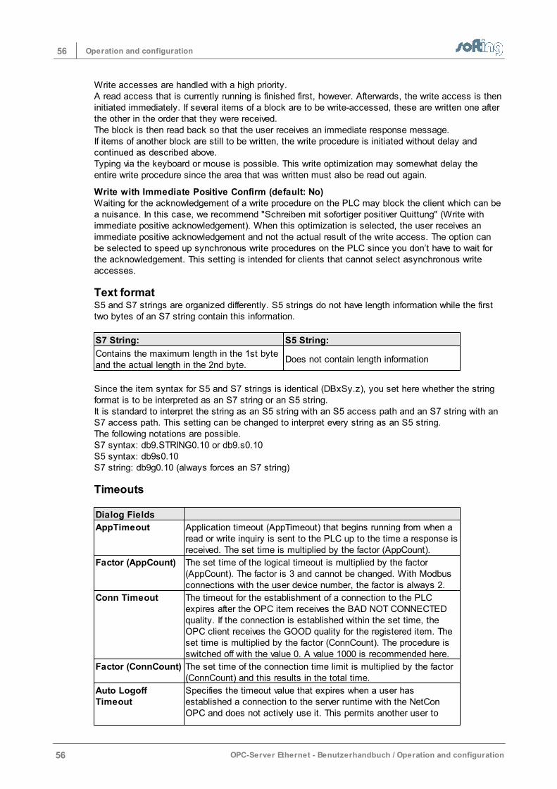
56 Operation and configuration
56 OPC-Server Ethernet - Benutzerhandbuch / Operation and configuration
Write accesses are handled with a high priority. A read access that is currently running is finished first, however. Afterwards, the write access is theninitiated immediately. If several items of a block are to be write-accessed, these are written one afterthe other in the order that they were received. The block is then read back so that the user receives an immediate response message.If items of another block are still to be written, the write procedure is initiated without delay andcontinued as described above.Typing via the keyboard or mouse is possible. This write optimization may somewhat delay theentire write procedure since the area that was written must also be read out again.
Write with Immediate Positive Confirm (default: No)Waiting for the acknowledgement of a write procedure on the PLC may block the client which can bea nuisance. In this case, we recommend "Schreiben mit sofortiger positiver Quittung" (Write withimmediate positive acknowledgement). When this optimization is selected, the user receives animmediate positive acknowledgement and not the actual result of the write access. The option canbe selected to speed up synchronous write procedures on the PLC since you don’t have to wait forthe acknowledgement. This setting is intended for clients that cannot select asynchronous writeaccesses.
Text formatS5 and S7 strings are organized differently. S5 strings do not have length information while the firsttwo bytes of an S7 string contain this information.
S7 String: S5 String:
Contains the maximum length in the 1st byteand the actual length in the 2nd byte.
Does not contain length information
Since the item syntax for S5 and S7 strings is identical (DBxSy.z), you set here whether the stringformat is to be interpreted as an S7 string or an S5 string.It is standard to interpret the string as an S5 string with an S5 access path and an S7 string with anS7 access path. This setting can be changed to interpret every string as an S5 string. The following notations are possible. S7 syntax: db9.STRING0.10 or db9.s0.10S5 syntax: db9s0.10S7 string: db9g0.10 (always forces an S7 string)
Timeouts
Dialog Fields
AppTimeout Application timeout (AppTimeout) that begins running from when aread or write inquiry is sent to the PLC up to the time a response isreceived. The set time is multiplied by the factor (AppCount).
Factor (AppCount) The set time of the logical timeout is multiplied by the factor(AppCount). The factor is 3 and cannot be changed. With Modbusconnections with the user device number, the factor is always 2.
Conn Timeout The timeout for the establishment of a connection to the PLCexpires after the OPC item receives the BAD NOT CONNECTEDquality. If the connection is established within the set time, theOPC client receives the GOOD quality for the registered item. Theset time is multiplied by the factor (ConnCount). The procedure isswitched off with the value 0. A value 1000 is recommended here.
Factor (ConnCount) The set time of the connection time limit is multiplied by the factor(ConnCount) and this results in the total time.
Auto LogoffTimeout
Specifies the timeout value that expires when a user hasestablished a connection to the server runtime with the NetConOPC and does not actively use it. This permits another user to
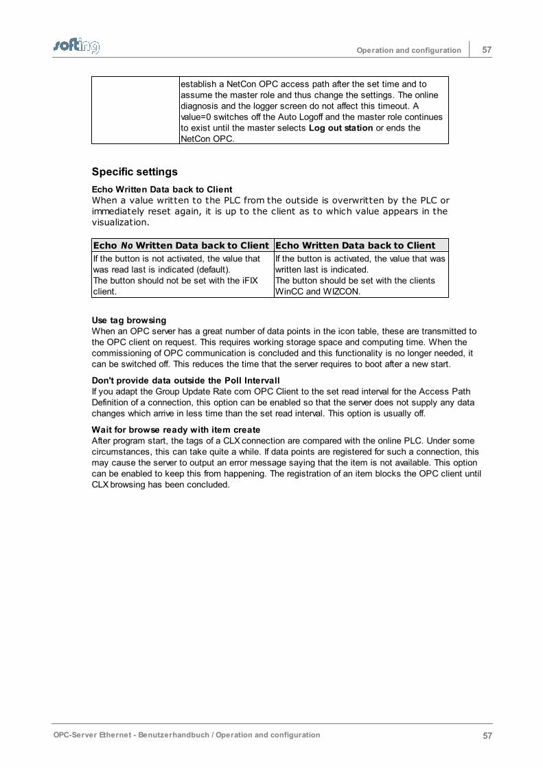
57Operation and configuration
OPC-Server Ethernet - Benutzerhandbuch / Operation and configuration 57
establish a NetCon OPC access path after the set time and toassume the master role and thus change the settings. The onlinediagnosis and the logger screen do not affect this timeout. Avalue=0 switches off the Auto Logoff and the master role continuesto exist until the master selects Log out station or ends theNetCon OPC.
Specific settings
Echo Written Data back to ClientWhen a value written to the PLC from the outside is overwritten by the PLC orimmediately reset again, it is up to the client as to which value appears in thevisualization.
Echo No Written Data back to Client Echo Written Data back to Client
If the button is not activated, the value thatwas read last is indicated (default).The button should not be set with the iFIXclient.
If the button is activated, the value that waswritten last is indicated.The button should be set with the clientsWinCC and WIZCON.
Use tag browsing When an OPC server has a great number of data points in the icon table, these are transmitted tothe OPC client on request. This requires working storage space and computing time. When thecommissioning of OPC communication is concluded and this functionality is no longer needed, itcan be switched off. This reduces the time that the server requires to boot after a new start.
Don't provide data outside the Poll IntervallIf you adapt the Group Update Rate com OPC Client to the set read interval for the Access PathDefinition of a connection, this option can be enabled so that the server does not supply any datachanges which arrive in less time than the set read interval. This option is usually off.
Wait for browse ready with item createAfter program start, the tags of a CLX connection are compared with the online PLC. Under somecircumstances, this can take quite a while. If data points are registered for such a connection, thismay cause the server to output an error message saying that the item is not available. This optioncan be enabled to keep this from happening. The registration of an item blocks the OPC client untilCLX browsing has been concluded.
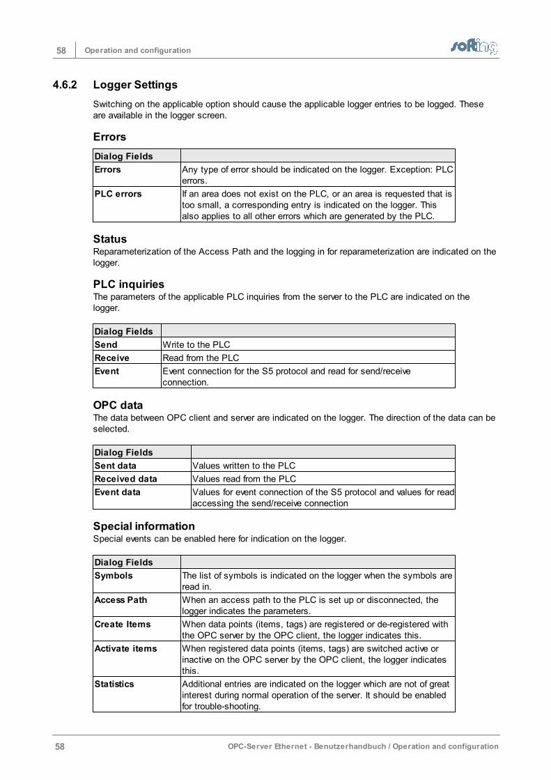
58 Operation and configuration
58 OPC-Server Ethernet - Benutzerhandbuch / Operation and configuration
4.6.2 Logger Settings
Switching on the applicable option should cause the applicable logger entries to be logged. Theseare available in the logger screen.
Errors
Dialog Fields
Errors Any type of error should be indicated on the logger. Exception: PLCerrors.
PLC errors If an area does not exist on the PLC, or an area is requested that istoo small, a corresponding entry is indicated on the logger. Thisalso applies to all other errors which are generated by the PLC.
StatusReparameterization of the Access Path and the logging in for reparameterization are indicated on thelogger.
PLC inquiriesThe parameters of the applicable PLC inquiries from the server to the PLC are indicated on thelogger.
Dialog Fields
Send Write to the PLC
Receive Read from the PLC
Event Event connection for the S5 protocol and read for send/receiveconnection.
OPC dataThe data between OPC client and server are indicated on the logger. The direction of the data can beselected.
Dialog Fields
Sent data Values written to the PLC
Received data Values read from the PLC
Event data Values for event connection of the S5 protocol and values for readaccessing the send/receive connection
Special informationSpecial events can be enabled here for indication on the logger.
Dialog Fields
Symbols The list of symbols is indicated on the logger when the symbols areread in.
Access Path When an access path to the PLC is set up or disconnected, thelogger indicates the parameters.
Create Items When data points (items, tags) are registered or de-registered withthe OPC server by the OPC client, the logger indicates this.
Activate items When registered data points (items, tags) are switched active orinactive on the OPC server by the OPC client, the logger indicatesthis.
Statistics Additional entries are indicated on the logger which are not of greatinterest during normal operation of the server. It should be enabledfor trouble-shooting.
59Operation and configuration
OPC-Server Ethernet - Benutzerhandbuch / Operation and configuration 59
4.6.3 Logger Memory Settings
In the logger memory dialog, it is specified whether the log entries should only be stored in workingstorage or also in a file. The time of the storage, the directory and the name of the file in which thelogs are saved is set.
Cache sizeSpecifies how much working storage is to be used for logging data. This buffer functions as a ringbuffer. When expanded, this means that more entries can be stored intermediately in workingstorage.
Use file loggingWhen this option is selected, the information is written to a file.
File settings
Max disk spaceSpecifies the size of the hard drive after which the old files should be deleted. This is supposed toprevent the hard drive from overflowing.
NOTE:
When the set size is reached, the logger deletes files from the directory without asking.If files from this directory are still needed, they should be archived early enoughbeforehand.
DirectorySpecifies the directory in which the log entries are saved.
File prefixThe file name is created from a consecutive number and the date plus time. The prefix is added infront.
Save every ...Specifies the time at which the file is to be saved if the buffer has not run in a circle in workingstorage. If the buffer is running faster in a circle, information is saved more often.
NOTE:
The number of write procedures is limited when saving to FLASH drives. To increase thelifespan of FLASH drives, write accesses should not be used often.
New file every ...Specifies when a new file is to be started. This simplifies the evaluation.
File Name ExampleThe output field shows an example of a file. This specifies where the logging files are located andhow the file names look.
60 Operation and configuration
60 OPC-Server Ethernet - Benutzerhandbuch / Operation and configuration
4.6.4 Station Password
The dialog screen for the creation or deletion of a code word is opened. This dialog can be used tospecify whether the user can change the server parameters after the program starts or whether theuser must identify him/herself with the code word first.
4.6.5 H1 MAC Address
The dialog screen shows the status of the H1 protocol driver. It allows you to set theMAC address of the network card.
The dialog screen is not offered unless the H1 protocol drive is installed.
The status of the network card can be determined in this dialog field and, ifnecessary, the current runtime address can be changed.
H1 license
This field indicates whether the installation of the H1 driver was successful.
Set MAC Address possibleThe MAC address of the network card to which the H1 protocol driver is linked cannot be overwrittenduring runtime (default setting). This setting can be changed with the registry entry“H1ChangeAddress. reg.”Select: “H1ChangeAddress.reg” via Start > Programs > INAT > PC-H1 > H1 Registry Scripts.The confirmation prompt should be confirmed with “Ja” (Yes). The change is confirmed with amessage. It is now possible to change the MAC address of the network card during runtime. Itshould be considered that although the operating system can be changed with the setting underwhich the MAC address can be changed, this may slow down the operating system.
NOTE:
The PC must be started again after the registry entry is changed!
Set MAC Address not possibleThe registry entry "H1ChangeAddress.reg" can be cancelled again with this registry entry“H1DoNotChangeAddress.reg."To do this, select "H1DoNotChangeAddress.reg" via Start > Programs > INAT > PC-H1 > H1Registry Scripts. The confirmation query should be answered with “Ja” (Yes). The change is confirmed with a message. It is now no longer possible to change the MAC address ofthe network card during runtime.
NOTE:
The PC must be started again after the registry entry is changed!
MAC AddressThe current MAC address of runtime is indicated here. To link the computer to an existing network, itmay be necessary to adjust the MAC address on the software side to the address structure used bythe network. The desired Ethernet address is entered in the MAC address dialog field and changedvia the button “<- Stellen” (set). The MAC address of the network card to which the H1 protocol driver is linked cannot be overwrittenduring runtime (default setting). This setting can be changed with the registry entry "H1ChangeAddress.reg".
ROM AddressThe hardware or Ethernet address of the network card is stored on a ROM chip on the network cardof the PC. It is read out and indicated at this location.
61Operation and configuration
OPC-Server Ethernet - Benutzerhandbuch / Operation and configuration 61
<- SetThe address that was entered in the MAC address field becomes active immediatelywith the "<- Set" button.
Set Addresses at server startBy activating the option "Set Addresses at server start" the address is changed thenext time the program starts.
NOTE:
A running connection is terminated when a new address is set.
NOTE:
The Ethernet address may only be assigned once in the network.
4.6.6 Server Symbol Edit
The server offers the possibility of using a symbolic name for a certain direct addresson the PLC. These symbolic names are stored in the icon file in the configurationdirectory with the name TcpIpH1.txt. This file can also be processed with any texteditor.
The dialog Server Symbol Edit offers a convenient way to process the icons.
New access pathExisting access path names of the icon file are listed in the drop-down box. One ofthese can be selected or a new name can be entered.
Edit topic symbolThis field contains the symbolic names followed by an equals sign (“=”) and the PLCaddress. Example for the S7:
Motor1.Auto_Ein=db5.X0.0Motor1.Drehzahl=db5.W2
Search / ReplaceThe lower area permits the search for/replacement of:- Individual character strings or whole words- Cursor backwards or forwards - Differentiate or not between upper and lower case letters- All of them or single ones
SaveSaves the icon information that was changed.
DeleteDelete all icons of the access path selected above.
EndLeaves the dialog and requests a new start so that the changes can take effect.
NOTE:
Symbols CANNOT be processed for CLX controllers!!!
The icon editor saves the icons in Unix file format. There is only a carriage return atthe end of a line and not a line feed. Some text editors cannot handle this and indicate
62 Operation and configuration
62 OPC-Server Ethernet - Benutzerhandbuch / Operation and configuration
all the lines in a single line. This can be corrected with some text editors andconverted into a PC form (e.g., Notepad++).
NOTE:
An icon import is available for S7 and Modbus controllers (Wago). This saves yourhaving to type in the information several times. For more information go to S7 SymbolImport and Modbus Symbol Import.
4.6.7 S7 Symbol Import
The S7 icon import dialog screen can be used to import icons from a Step7 program tothe icon table of the server. During OPC client browsing the icon names are indicatedthe way they are also used in Step7. The following steps are required.
In the menu Symbols - S7 Symbol ImportFirst, select the Step7 project with the file ending s7p.
• Then select the PLC program in the Step7 project.• The list of programmed DBs is indicated. Or the icon table can be displayed. To dothis, select the Show All DBs option or Show Symbol Table. • Then select the Access Path from the list of available ones or enter one in the inputfield New access path.• You can now select which symbol you want to import:
Symbol Table
All symbolic names which are stored in the icon table of the S7program are imported. These include the symbols for inputs,outputs and symbols in the flag area.
DBs
The symbolic variable names of the data blocks of the S7 programare imported. In addition, only those blocks can be selected fromthe PLC blocks list that are also supposed to be visible on theserver.
Resolve arrays in addition
Every single element of an array is given its own icon name.
NOTE:
This may greatly enlarge the icon file of the OPC server and thistakes more time during program start.
It is usually switched off.
Add comments
When the project contains commentaries for individual icons, thesecommentaries are also visible in the icon table although theycannot be registered as items. This is usually switched off. ExampleMotor1.EIN=M1.1 (Motor1.ON=M1.1)Motor1.EIN-comment (Motor1.ON-comment)=(=Motor1 is switchedon with this flag).
NOTE:
The commentaries should not be registered since this would causean error message.
PLC Blocks
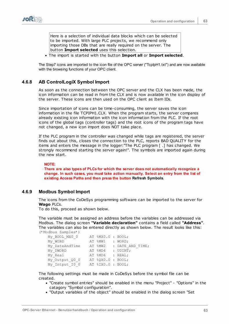
63Operation and configuration
OPC-Server Ethernet - Benutzerhandbuch / Operation and configuration 63
Here is a selection of individual data blocks which can be selectedto be imported. With large PLC projects, we recommend onlyimporting those DBs that are really required on the server. Thebutton Import selected uses this selection.
The import is started with the button Import all or Import selected. The Step7 icons are imported to the icon file of the OPC server ("TcpIpH1.txt") and are now availablewith the browsing functions of your OPC client.
4.6.8 AB ControlLogiX Symbol Import
As soon as the connection between the OPC server and the CLX has been made, theicon information can be read in from the CLX and is now available in the icon display ofthe server. These icons are then used on the OPC client as Item IDs.
Since importation of icons can be time-consuming, the server saves the iconinformation in the file TCPIPH1.CLX. When the program starts, the server comparesalready existing icon information with the icon information from the PLC. If the rooticons of the global tags (controller tags) and the root icons of the program tags havenot changed, a new icon import does NOT take place.
If the PLC program in the controller was changed while tags are registered, the serverfinds out about this, closes the connection to the PLC, reports BAD QUALITY for theitems and enters the message in the logger:"The PLC program [ .] has changed. Westrongly recommend starting the server again!". The symbols are imported again duringthe new start.
NOTE: There are also types of PLCs for which the server does not automatically recognize achange. In such cases, you must take action manually. Select an entry from the list ofexisting Access Paths and then press the button Refresh Symbols.
4.6.9 Modbus Symbol Import
The icons from the CoDeSys programming software can be imported to the server for Wago PLCs. To do this, proceed as shown below.
The variable must be assigned an address before the variables can be addressed viaModbus. The dialog screen "Variable declaration" contains a field called "Address". The variables can also be entered directly as shown below. The result looks like this: (*Modbus Samples*) My_BOOL_MX0_0 AT %MX0.0 : BOOL; My_WORD AT %MW1 : WORD; My_DateAndTime AT %MW2 : DATE_AND_TIME; My_DWORD AT %MD4 : UDINT; My_Real AT %MD6 : REAL; My_Output_Q0_0 AT %QX0.0 : BOOL; My_Intput_I0_0 AT %IX0.0 : BOOL;
The following settings must be made in CoDeSys before the symbol file can becreated.
"Create symbol entries" should be enabled in the menu "Project" - "Options" in thecatagory "Symbol configuration"."Output variables of the object" should be enabled in the dialog screen "Set

64 Operation and configuration
64 OPC-Server Ethernet - Benutzerhandbuch / Operation and configuration
object attributes" which can be accessed via the button "Configure symbols".
After the project is compiled, a file with the project name and the ending “.SYM” iscreated. The server needs to import the icons.
The dialog screen is called in the menu "Symbols" - "Modbus Symbol Import". The *.SYM file is selected first. The access path is then selected to which the icons are to be imported. Thename should be located in the "New access path" field. If the connection has notyet been set up, the new name can be specified here. The icons are imported when the "Import" button is pressed.
The server must be started again before the icons become available in Browsing. A text can be added at the beginning or end of all icon names with the "Prefix" and"Postfix" fields. Under normal circumstances, these fields remain empty.
65Operation and configuration
OPC-Server Ethernet - Benutzerhandbuch / Operation and configuration 65
4.6.10 Directory for Configuration File
All established connections are stored automatically in a configuration file. The standard path for theconfiguration file is under Windows XP "c:\Dokumente und Einstellungen\AllUsers\Dokumente\INAT.“ And for later editions of Windows "c: \Users\Public\Documents\INAT"and the file name TcpIpH1.NET. The path is automatically stored in the OpcServer.ini file which islocated in the above stated path so that the configuration file is loaded the next time the server startsand the connections contained therein are available. The icons are also stored in the same directoryin the file TcpIpH1.txt. The intermediately stored icons for the CLX connections are stored in the fileTcpIpH1.clx.
NOTE:
The file name of the configuration file CANNOT be changed. It must have the nameTcpiph1.net.
Changing the directory of the configuration fileThe path for the configuration file can be entered in the dialog screen OPC ServerSystem Settings in the input field Path for the configuration file, or via the >>button to search through and select. To accept the change, the server must bestarted again.
Saving several configuration filesThere is no limit to the number of configuration files that can be created except that the files must belocated in different directories.
Starting the server with another configuration fileThis is not possible unless the server is registered as an application! If the server is to be started with a different configuration file than the one savedlast, the following command line should be entered in the request for input. TCPIPH1.EXE /d:pathRemember:
- A blank between.EXE and /d.- The path is the complete, asbolute or relative path of the configuration file. - If it contains blanks, the path should be entered between quotation marks.
Example:TCPIPH1.EXE /d:C:\Data\Project1if the configuration file is located under C:\Data\Project1 or is to be set up here anew.
The applicable path (e.g., C:\Data\Projekt1) is then located as the directory for theconfiguration file in the menu Settings > Server System Settings in the dialogscreen OPC Server System Settings.
66 Operation and configuration
66 OPC-Server Ethernet - Benutzerhandbuch / Operation and configuration
4.7 Dialog Screens
This chapter describes the dialog screens which were not described in the chapters Configuration orConnection (Access Path).The following dialog screens are described.
Network Settings (Station Parameters)VersionsLicense OverviewLicense entryAboutEntering the PasswordSelecting the StationNew StationStation not found
4.7.1 Network Settings (Station Parameters)
The dialog screen shows the information on the own station. The values cannot be changed. The dialog screen shows the information that has been determined.
Station NameComputer name of the PC MAC (Ethernet) Address The MAC address of the network card. Each station in the Ethernet network has anunambiguous Ethernet address.
TCP/IP Station Parameter:
Use DHCPIt cannot be precisely determined whether the automatic configuration is switched onvia a DHCP.
IP AddressThis determines the address of the station when used with the TCP/IP protocol. See IPAddresses. Subnet maskThis determines which station inquiries are allowed to reach the active network.Addresses whose masked portion differs are sent to the router. If no router isparameterized, the subnet mask is meaningless. Domain NameThe domain name is used for symbolic inquiries when no domain is explicitly specifiedthere. That is usually the case with names which do not contain a dot.
Maximum three Domain Server Addresses:
DNS AddressesThese addresses determine the servers which resolve the symbolic Internet names intoIP number addresses in their network Router Addresses
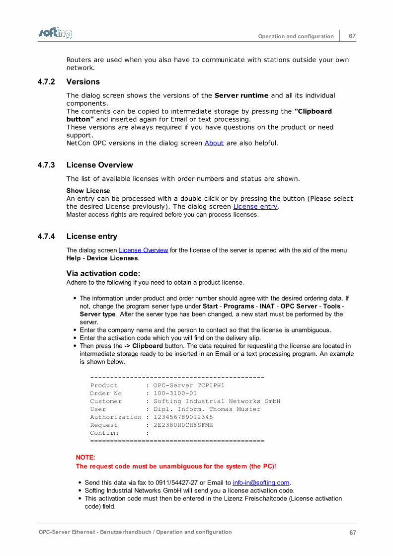
67Operation and configuration
OPC-Server Ethernet - Benutzerhandbuch / Operation and configuration 67
Routers are used when you also have to communicate with stations outside your ownnetwork.
4.7.2 Versions
The dialog screen shows the versions of the Server runtime and all its individualcomponents. The contents can be copied to intermediate storage by pressing the "Clipboardbutton" and inserted again for Email or text processing. These versions are always required if you have questions on the product or needsupport. NetCon OPC versions in the dialog screen About are also helpful.
4.7.3 License Overview
The list of available licenses with order numbers and status are shown.
Show LicenseAn entry can be processed with a double click or by pressing the button (Please selectthe desired License previously). The dialog screen License entry.Master access rights are required before you can process licenses.
4.7.4 License entry
The dialog screen License Overview for the license of the server is opened with the aid of the menuHelp - Device Licenses.
Via activation code:Adhere to the following if you need to obtain a product license.
The information under product and order number should agree with the desired ordering data. Ifnot, change the program server type under Start - Programs - INAT - OPC Server - Tools -Server type. After the server type has been changed, a new start must be performed by theserver. Enter the company name and the person to contact so that the license is unambiguous.Enter the activation code which you will find on the delivery slip. Then press the -> Clipboard button. The data required for requesting the license are located inintermediate storage ready to be inserted in an Email or a text processing program. An exampleis shown below.
--------------------------------------------Product : OPC-Server TCPIPH1Order No : 100-3100-01Customer : Softing Industrial Networks GmbHUser : Dipl. Inform. Thomas MusterAuthorization : 123456789012345Request : 2E2380H0CH8SFMHConfirm : ============================================
NOTE:
The request code must be unambiguous for the system (the PC)!
Send this data via fax to 0911/54427-27 or Email to [email protected] Industrial Networks GmbH will send you a license activation code. This activation code must then be entered in the Lizenz Freischaltcode (License activationcode) field.
68 Operation and configuration
68 OPC-Server Ethernet - Benutzerhandbuch / Operation and configuration
The License status field indicates whether the entry is correct and the function has beenactivated.
NOTE:
When used with RAID systems or Cluster computers, licensing is only possible viadongle!
4.7.5 About
This dialog screen shows the copyright, the versions of software and the addresses tocontact if you have questions, ideas or need support. These versions are required if you have questions or need product support. Theversions of the Server-Runtime are also required. They are shown in the Versionsdialog screen.
Licensing conditions
4.7.6 Entering the Password
This dialog screen allows you to set or delete the code word. The screen is also called up duringregistration. A code word provides protection against someone changing the configuration.
The dialog screen is called for this in the menu Station - Station Password. The password isentered and confirmed a second time. This means that the Netcon OPC is logged in and theconfiguration can be changed.
The menu Station - Station Logoff disables the right to perform write accesses. This means thatonly those dialog screens can be opened that do not require write accessing. Online diagnostics andlogger are still possible, however.
The status field next to the toolbar under the menu shows whether the parameters can be changed.
4.7.7 Selecting the Stations
When the NetCon OPC is started via Start -> Programs) ->INAT -> OPC Server ->NetCon OPC, the stations are selected which are to be communicated with. When theNetCon OPC is started via the Server Tray, this dialog capability is not available.
The station screen Select station is opened during the Configuration via TCP/IP orConfiguration via H1.
All stations with an arrow (->) at the beginning of the line are stations which arecurrently available online on the network. They are automatically recognized by the NetCon OPC. All PCs with servers are shown.
NOTE:
Stations behind routers are not automatically recognized. A direct connection must beestablished to them via the " New" button.
Select stationA connection to the appropriate station is established by double clicking on the desiredstation (or confirming with the “OK” button). This connection establishment is time-monitored at approx. 3 sec. Connection is made: The main screen Access Path List isopened.Connection is not made: If no reply is received within 3 sec, connection establishmentis terminated.
69Operation and configuration
OPC-Server Ethernet - Benutzerhandbuch / Operation and configuration 69
NewIf the station was not found in the automatic online indication (parameterization viaIP) because it is located outside its own network, a direct connection to the stationcan be configured with this button. This is done in the New Station dialog screen.
EditThe parameters of the station which was created with the dialog New Station can bechanged here.
DeleteThe parameters of the station can be deleted here. An “are you sure?” questionappears beforehand. Remember that deletions cannot be reversed.
Scan for stationsStarts the station search and the automatic recognition of the stations and serveronline. Remember that only stations in the local network can be reached.
Execute station scan on startStarts the search for stations automatically when this dialog screen is opened. Sincethis can take a long time if there are many stations in the network, this function canbe switched off.
Use TimeoutThis button should be switched on when the connection timeout is used. Normally thisbutton is off, however.
TimeoutThe connection timeout can be used to change the default timeout for a stationsearch of 3 sec specifically for this connection. For example, this is useful forconnection on the Internet for which the life frames have been deactivated. Thisincreases the reaction time for connection interruptions (e.g., for cable breaks).
4.7.8 New Station
If a connection could not be established with the desired station and the dialog screen Station notfound appears, a direct connection can be configured to this station. The entry is then added to thelist of available stations and the entry appears in the dialog screen Select station. If the station isavailable online, this is indicated with an arrow (->) preceding the station when the station searchwas performed.
NameThe name that is to be indicated in the list.
H1A connection is to be established via the H1 protocol. MAC address and TSAP are specified.
TCP/IPA connection is to be established via the TCP/IP protocol. IP address and port number are indicated.
ExtendedExpands the dialog for entry of additional parameters.
H1 Settings
MAC AddressThe MAC address of the station which is to be configured and diagnosed.
Default TSAP / Special TSAPThe TSAP for H1 or RFC1006 connections.
TCP/IP Settings
70 Operation and configuration
70 OPC-Server Ethernet - Benutzerhandbuch / Operation and configuration
IP AddressThe IP address or DNS name of the station which is to be configured and diagnosed. 127.0.0.1 addresses the local device.
Default Port / Special PortThe OPC server uses port 982.The INAT devices use 997, newer devices also use 982.If configuration and diagnosis is to take place via RFC1006, the TSAP must be entered.
StandardReduces the dialog and only shows just a few parameters.
Optional Product SelectThese entries are ignored.
4.7.9 Station not found
The dialog screen shows "A timeout occured".A station may not be able to be found for the following reasons.
OPC-ServerThe server service is concluded
Configuration via TCP/IP or Configuration via H1The selected station is off. A network cable is not plugged in or is defective. A switch, HUB, router or gateway is not on. The station cannot be reached because it is located behind a router.The protocol which is to be used for the connection with the station (H1 or TCP/IP) is not correctly installed or configured on the operator computer. H1 or TCP/IP is not correctly installed or configured for the other network station.A station (e.g., a reference router) has blocked further transmission of theframesThe firewall is not configured correctly.
NOTE:
Stations behind routers are not automatically recognized. A direct connection must beestablished to them via the “Neu” (New) button (see New Station )
71Operation and configuration
OPC-Server Ethernet - Benutzerhandbuch / Operation and configuration 71
4.8 Menu
This menu offers the following menu items.
FileConnectionDiagnosticsStationSettingsSymbolsHelp
4.8.1 File
This menu item offers the following points.
RefreshThe connection to the OPC server runtime is established again. If a code word is set, it will need tobe entered again before you can begin processing.
Restart ServerThe server runtime is started again after a security check. After a new server start, the data points (items) must be registered again on the OPC client.This function requires master access.
Close WindowConcludes the configuration of the server.
4.8.2 Connection
This menu item has the following points.
Show Access Path ListThe main screen is switched from Online Diagnosis to Access Path List. The list with the configuredconnections is indicated and can be processed.
Switch on/offAn access path can be switched inactive if it is not supposed to communicate with the PLC. Thismeans that it can be temporarily turned off without having to delete and reenter. See Switch connection inactive.This function requires master access.
New Access PathA new access path can be entered and then the dialog screen New Connection (Access Path)opens. First, the name and type of connection are selected. Then the necessary parameters are entered. The connection parameters take immediate effect for most connections. However, a server new startmay be necessary for some of them. An appropriate dialog screen points this out.This function requires master access.
72 Operation and configuration
72 OPC-Server Ethernet - Benutzerhandbuch / Operation and configuration
Edit Access PathThe parameters of the selected access path can be processed. The dialog screen Edit Connection(Edit Access Path) opens.Master access is required for this function.
Copy Access PathThe access path can be copied. The dialog screen Copy Connection (Copy Access Path) opens.When saving, remember that the name must be adjusted accordingly. Master access is required for this function.
Delete Access PathThe access path can be deleted with the dialog screen Delete Connection (Delete Access Path)after a security check. You can also decide whether the related icons are to be deleted too. Masteraccess is required for this function.
4.8.3 Diagnostics
The menu item offers the following points.
Show DiagnosticsThe main screen is switched from the Access Path List to the Online Diagnosis. The list with therunning access paths (connections) is indicated. Colored identification makes it easy to see whether “everything is okay” or whether problems haveoccurred. Statistics concerning sent and received frames and data points (tags, items) are indicated for everyaccess path. The requested data areas of the PLCs that reported the number and have active data points are alsoindicated.
LoggerThe Logger screen is opened. The logged messages are indicated there. This screen can be opened parallel to the rest of operator control of the program. When the loggerscreen is open, you can continue configuring and other operations.
Logger SettingsThe dialog screen Logger Settings is opened. There you can select which events are to be recordedon the logger.The file and memory settings of the logger are available under Settings in the logger screen.
4.8.4 Station
The menu item has the following sub items.
Station LoginThe dialog screen Entering the Password for entering the code word is opened. Here you can log inand obtain write access rights for changing the server parameters.
Station LogoffThis is where you can log out and cancel access rights for changing the server parameters. Anotherstation can then log in and change the server parameters.
Station PasswordThe dialog screen Entering the Password for creating or deleting a code word is opened. Here youcan specify whether the user can change the server parameters after program start or whether he
73Operation and configuration
OPC-Server Ethernet - Benutzerhandbuch / Operation and configuration 73
must register with the code word first.
H1 AddressThe dialog screen H1 MAC Addresses for indicating and changing the H1 MAC address is opened.There the MAC address can be indicated, changed and highlighted for setting during the server start.Master access is required for executing this function with write access rights. The menu item is thenonly offered when the H1 protocol driver is installed.
4.8.5 Settings
This menu item has the following sub items.
Server System SettingsThe dialog screen Server System Settings is opened and enables you to change the server settings.
DCOM SettingsA management console of the operating system is started for the administration of the componentservices.The administration program for component services can be used to configure and manage the COMcomponents and COM+ applications. If you don’t have access rights, the DCOMCNFG.exe programcan also be started directly from the workplace interface.
4.8.6 Symbols
This menu item has the following sub items.
Symbol EditThe dialog screen Server Symbol Edit is opened. The symbol editor can be used to assign iconnames directly to PLC addresses. These then also appear in the browsing interface for the OPC client. Master access is required for editing the icons.
S7 Symbol ImportThe dialog screen S7 Symbol Import is opened. This screen can be used to import the variables of aSTEP7 PLC program to the server and assign an access path. These are then available to the OPCclient on the browsing interface. Master access is required for the execution of this function.
CLX Symbol ImportThe dialog screen AB ControlLogiX Symbol Import is opened. This screen can be used to delete theintermediately stored information of the variables of a PLC program and reload. This must be done when the PLC program has been changed. Master access is required for the execution of this function.
Modbus Symbol ImportThe dialog screen Modbus Symbol Import is opened. This screen can be used to import the variablesof a CoDeSys PLC program for a Wago PLC to the server and assign an access path. These arethen available to the OPC client on the browsing interface. Master access is required for the execution of this function.
74 Operation and configuration
74 OPC-Server Ethernet - Benutzerhandbuch / Operation and configuration
4.8.7 Help
This menu item has the following sub items.
HelpStarts the Help Overview of the online help.
VersionsOpens the Versions dialog screen and shows the versions of the server runtime.
Device LicensesOpens the License Overview dialog screen and lets you monitor and process the server licenses.
AboutOpens the About dialog screen and indicates the manufacturer and the versions of the program.
75Operation and configuration
OPC-Server Ethernet - Benutzerhandbuch / Operation and configuration 75
4.9 Troubleshooting
Problem: Access of the OPC server to the S7 controller doesn’t work. Solution: First, ping the S7 controller. If you don’t receive an answer, there is a network problem. Oryou have used the wrong IP address or a router is located in the network and the gateway address isnot set at all or is set incorrectly. If pinging is possible, check the following Access PathEinstellungen (access path settings):1. SPS-Header (PLC header) must be deactivated. 2. RFC1006 should always be activated. Addressing is done with TSAPs and not via ports.3. The easiest way to access the S7 is to use standard TSAPs.
NOTE: Be sure that the standard TSAPs are entered in the HEX window!
Problem: After 72 hours, the OPC server doesn’t supply any more newvalues for the items. Solution: The server is still not licensed and the demo time has expired. Start the server again andall the functions of the server will be available to you again for 72 hours. License the server with thehardware key (dongle) to eliminate this time limitation.
Problem: The demo time of 72 hours is not reached.Solution: The system time of the PC was probably changed. They can be caused for the followingreasons.
• Some programs change the system time because they are not compatible with the operatingsystem (e.g., STEP5 V6.x under Win2000 – this combination has not been released). • Some programs which are actually supposed to synchronize the system time on the network,change the system time for a minimal amount of time. The user usually doesn’t notice this.
Check the logger for how long the server has actually run.
Problem: The OPC server “freezes up” and can no longer be operated. Solution: Probably very many or all logger functions are activated on the OPC server logger. Withsome PCs, this can cause the server to freeze up. The logger functions should then be switched offwith the Logger Settings dialog screen (default is if only "error" and "PLC error" are activated and theserver starts running again).
Problem: On the NetCon OPC, the user is requested to enter a code wordalthough none is set. Solution:
The NetCon OPC was probably started several times. Only a NetCon OPC can be the master.All the others are slaves and only have write access rights after the code word is entered. A value other than 0 has been entered for the Auto Logoff Timeout in the Server SystemSettings dialog screen. After this set time, the NetCon OPC loses its master role if it is notactively operated

Accessories
Chapter 5
77Accessories
OPC-Server Ethernet - Benutzerhandbuch / Accessories 77
5 Accessories
This chapter describes the following subjects.
NetCon OPCSelecting the Server TypeServer TrayLoggerOPC Client
5.1 NetCon OPC
The NetCon OPC program is the graphic interface (GUI) for configuring and diagnosing (starting withthe version 4.05 OPC server). GUI connects to the OPC server core via TCP/IP (Port 982). Thisallows remote access to OPC servers which are running on another PC and can be accessed on thenetwork.
Program startNetCon OPC can be started in different ways. It provides different functionalities depending on how itis started.
Via the Server TrayUsually the program is started via the Server Tray, menu item Server Status - NetCon OPC.The local OPC server is configured with this. The program starts with the Online-Diagnosis.Via Start - Programs - INAT - OPC Server - NetCon OPCIf an OPC server is to be configured on another PC and diagnosed, this is themethod to use. The program starts with the start screen and permitsconfiguration via TCP/IP or a configuration via H1 (if the H1 protocol driver isinstalled). This method can then be used to open the station screen Selectingthe Station and the connection can be established to the desired server. If you select thismethod, the program is started with the command line parameter -s which means that only theserver in the network is offered for selection.In Explorer, double-click Paramqlnt.exe.Starting the program with this method causes all OPC servers and INAT devices(echolink, echocollect and echochange) to be indicated in the station screen Selection the Station. This is not the usual method.
PasswordChanging server parameters and settings can be protected by setting a code word. This is done inthe menu Station – Station Password. If a password is set, this can be registered via the menuStation - Station Login and deregistertered via Station – Station Logoff. Monitoring anddiagnosing are also possible without logging in. When the server is installed again, it should not have a code word (i.e., write accesses are alsopermitted from Remote). If you forget the code word, the only thing to do is to locally access TCPIPH1.Net with a text editorand delete the code word in section [Own address] of the entry [station password =...] and thenperform a new start of the server. If the server refuses to perform a new start due to the missingaccess rights, the PC must perform a new start.
Master-SlaveThe OPC server allows accessing by several NetCon OPCs. To prevent them from influencing eachother, access is handled by a master-slave procedure. The registration procedure is performed as shown below.
If no NetCon OPC is registered yet, the first one registers. If a code word is set, then as slave
78 Accessories
78 OPC-Server Ethernet - Benutzerhandbuch / Accessories
or otherwise master. All others register as slaves. If a code word is set, the code word is queried during the first write command. If the code word is entered correctly, it is no longer queried after that. If this is a slave, it can register itself as master via the menu Station - Station Login. It cando this then when the master has de-registered itself in the meantime. remote NetCon OPC cannot take the master role away from anyone. A local NetCon OPC can withdraw the master role from a remote master and become masteritself. The remote master then becomes the slave. However, it does not notice this until thefirst write access when it has to enter a code word. When a connection is briefly interrupted, the code word does not have to be entered again. When the server performs a new start, the code word must be entered again. The Auto Logoff function de-registers the master automatically after 100 s (1.5 min.) if theconnection is interrupted. After 1000 s (16.6 min.) when the user is logged onto the NetConOPC and does nothing more than status or logger. If it does do something else, the 1000 sstarts again. The value Auto Logoff Timeout can be changed in the dialog screen ServerSystem Settings Auto Logoff can be disabled with 0. A master can give up its master role via the menu Station - Station Logoff.A slave can try to gain write access rights with the login even when no code word is set.
Operator Control and Configuration The graphic interface of the NetCon OPC is described in detail in the section Operation andconfiguration.
LoggerThe exteral Logger can be configured on the NetCon OPC. The contents of the logger are shown inthe Logger dialog screen.
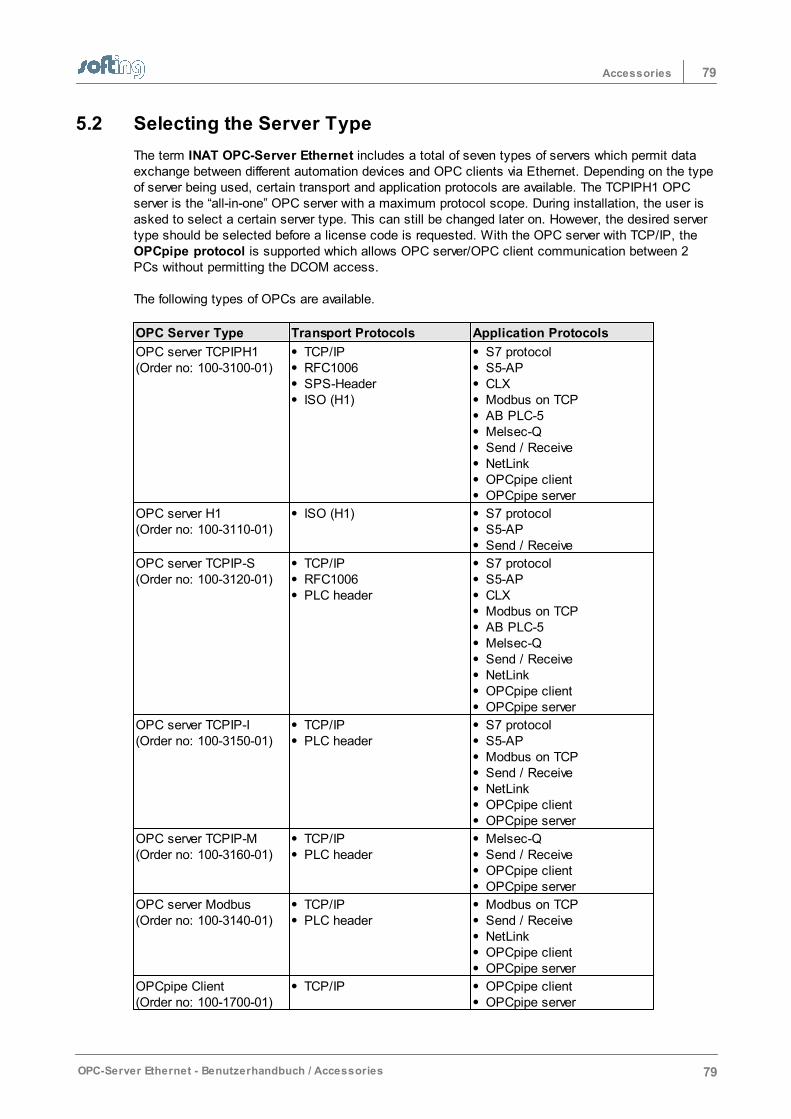
79Accessories
OPC-Server Ethernet - Benutzerhandbuch / Accessories 79
5.2 Selecting the Server Type
The term INAT OPC-Server Ethernet includes a total of seven types of servers which permit dataexchange between different automation devices and OPC clients via Ethernet. Depending on the typeof server being used, certain transport and application protocols are available. The TCPIPH1 OPCserver is the “all-in-one” OPC server with a maximum protocol scope. During installation, the user isasked to select a certain server type. This can still be changed later on. However, the desired servertype should be selected before a license code is requested. With the OPC server with TCP/IP, the OPCpipe protocol is supported which allows OPC server/OPC client communication between 2PCs without permitting the DCOM access.
The following types of OPCs are available.
OPC Server Type Transport Protocols Application Protocols
OPC server TCPIPH1(Order no: 100-3100-01)
TCP/IPRFC1006SPS-HeaderISO (H1)
S7 protocolS5-APCLXModbus on TCPAB PLC-5Melsec-QSend / ReceiveNetLinkOPCpipe clientOPCpipe server
OPC server H1(Order no: 100-3110-01)
ISO (H1) S7 protocolS5-APSend / Receive
OPC server TCPIP-S(Order no: 100-3120-01)
TCP/IPRFC1006PLC header
S7 protocolS5-APCLXModbus on TCPAB PLC-5Melsec-QSend / ReceiveNetLinkOPCpipe clientOPCpipe server
OPC server TCPIP-I(Order no: 100-3150-01)
TCP/IPPLC header
S7 protocolS5-APModbus on TCPSend / ReceiveNetLinkOPCpipe clientOPCpipe server
OPC server TCPIP-M(Order no: 100-3160-01)
TCP/IPPLC header
Melsec-QSend / ReceiveOPCpipe clientOPCpipe server
OPC server Modbus(Order no: 100-3140-01)
TCP/IPPLC header
Modbus on TCPSend / ReceiveNetLinkOPCpipe clientOPCpipe server
OPCpipe Client(Order no: 100-1700-01)
TCP/IP OPCpipe clientOPCpipe server
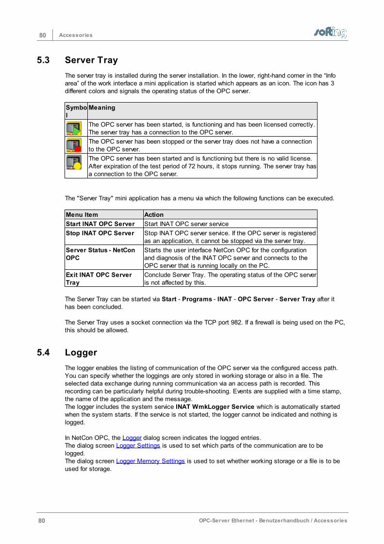
80 Accessories
80 OPC-Server Ethernet - Benutzerhandbuch / Accessories
5.3 Server Tray
The server tray is installed during the server installation. In the lower, right-hand corner in the “Infoarea” of the work interface a mini application is started which appears as an icon. The icon has 3different colors and signals the operating status of the OPC server.
Symbol
Meaning
The OPC server has been started, is functioning and has been licensed correctly.The server tray has a connection to the OPC server.
The OPC server has been stopped or the server tray does not have a connectionto the OPC server.
The OPC server has been started and is functioning but there is no valid license.After expiration of the test period of 72 hours, it stops running. The server tray hasa connection to the OPC server.
The "Server Tray" mini application has a menu via which the following functions can be executed.
Menu Item Action
Start INAT OPC Server Start INAT OPC server service
Stop INAT OPC Server Stop INAT OPC server service. If the OPC server is registeredas an application, it cannot be stopped via the server tray.
Server Status - NetConOPC
Starts the user interface NetCon OPC for the configurationand diagnosis of the INAT OPC server and connects to theOPC server that is running locally on the PC.
Exit INAT OPC ServerTray
Conclude Server Tray. The operating status of the OPC serveris not affected by this.
The Server Tray can be started via Start - Programs - INAT - OPC Server - Server Tray after ithas been concluded.
The Server Tray uses a socket connection via the TCP port 982. If a firewall is being used on the PC,this should be allowed.
5.4 Logger
The logger enables the listing of communication of the OPC server via the configured access path.You can specify whether the loggings are only stored in working storage or also in a file. Theselected data exchange during running communication via an access path is recorded. Thisrecording can be particularly helpful during trouble-shooting. Events are supplied with a time stamp,the name of the application and the message.The logger includes the system service INAT WmkLogger Service which is automatically startedwhen the system starts. If the service is not started, the logger cannot be indicated and nothing islogged.
In NetCon OPC, the Logger dialog screen indicates the logged entries. The dialog screen Logger Settings is used to set which parts of the communication are to belogged. The dialog screen Logger Memory Settings is used to set whether working storage or a file is to beused for storage.
81Accessories
OPC-Server Ethernet - Benutzerhandbuch / Accessories 81
5.5 OPC Client
Im Lieferumfang des OPC-Servers ist ein OPC Test-Client enthalten. Dieser OPC-Clientwird während der Installation des OPC-Servers mit installiert. Der Client ist sehr einfachzu bedienen und ermöglicht ein Testen des OPC-Servers.
Indicate available OPC serversThe OPC client determines the OPC servers which are installed on the PC and offersthem in the menu via "Server" > "Connect...". The client searches through theregistry of the local computer and generates a list of available OPC servers.
Connect server and clientIf the Ethernet OPC server "INAT TcpIpH1 OPC Server" is selected and confirmedwith OK, this will automatically be started. If an error message appears, this may bebecause of the following reasons. The OPC Core Components are not installed correctly ==> please reinstall. The Start rights are not assigned in the DCOM settings. Please permit the access. Forfurther information, go to DCOM Configuration – General
Add groupsTo set up a new OPC group, the selection is made in the menu Group > Add Group. Any groupname can be selected. The update rate (msec) specifies at what maximum data rate the individualdata points will receive new values.
Add ItemTo add items to the group, the group is highlighted and then selected with the menu Item > Add Item. Each item must have an item ID and access path. In addition, therequired data type and active status can be selected. The access path must correspond exactly with the name which was used when theaccess path was set up in NetCon OPC. An own dialog screen for the access path isnot available for some OPC clients. With these clients the access path forcommunication with the server can be specified as shown below.
[Access Path Name]Item-ID or Access Path Name.Item-IDExample:[PLC1]DB5.W0PLC1.DB5.W0 In the dialog screen to the bottom left all icon names are indicated which can be usedinstead of the item IDs. The OPC server provides these via the browsing interface.
See also:
Server Symbol EditS7 Symbol ImportModbus Symbol ImportAB ControlLogiX Symbol Import
When the item is specified, Validate can be used to check whether the server hasaccepted the item.
The item is registered with the server with OK. The variable is indicated in the maindialog screen with the value Quality and Updates.

Item Syntax
Chapter 6
83Item Syntax
OPC-Server Ethernet - Benutzerhandbuch / Item Syntax 83
6 Item Syntax
This chapter describes the item syntax which can be used to set up items (tags) for thecorresponding connection (access path).
S7 Item SyntaxS5 Item SyntaxModbus Item-SyntaxPLC-5 / SLC Item SyntaxMELSEC-Q Item SyntaxSend/Receive Item SyntaxOPCpipe Item Syntax
The following chapters apply in general.
ArraysSuffixeData TypesSpecial Items
84 Item Syntax
84 OPC-Server Ethernet - Benutzerhandbuch / Item Syntax
6.1 S7 Item Syntax
The S7 item syntax is set up as shown below:
[Group.]<Area><Data type><Start address>[.Array size][Suffix]
If the data type is BOOL, the bit number is required.
[Group.]<Area><Data type><Start address><.Bit no.>[.Array size][Suffix]Legend: <> Mandatory [ ] optional
<Area>Syntax Orientation1 >Access Rights Notes
Data block DBx.V synonym DB1
BYTE Read / write With blocks,specification of ablock number x isrequired (x = 1 to65535). A period or acomma must appearafter the blocknumber.
Instance block DIx. BYTE Read / write
Flag M or F BYTE Read / write
Timer T WORD Read
Counter Z or C WORD Read / write
Input E or I BYTE Read
Output A or O or Q BYTE Read / write
I/O input PE or PI BYTE Read
I/O output PA or PO or PQ BYTE Read / write1BYTE-oriented means that a byte is addressed for each physical address.
WORD-oriented means that a w ord (16 bits) is addressed for each physical address.
<Data type>
Type Syntax DB / DI F (M) I/O (E/A) PE /PA C/TWithArray
Sig.Suffixes
OPCDatatype
BITVT_BOOL
X DB5.X4.3 MX1.3 ------- ------- ------- ------- -------
BITVT_BOOL
DB5.4.3 M1.3 E4.3I4.3A4.3O4.3
PE4.5PI4.5PA1.3PO1.3
------- ------- -------
BYTEVT_UI1
BByte
DB5.B2DB5.Byte2
MB4MByte4FB4FByte4
EB4EByte4IB4IByte4AB5AByte5OB5OByte5
PEB4PEByte4PIB4PIByte4PAB5PAByte5POB5POByte5
------- DB5.B2.4DB5.Byte2.4MB4.3MByte4.3FB4.4FByte4.4POB5.3etc.
BABCDRIRU
VT_BOOL |VT_ARRAYVT_I2VT_R4VT_R4
WORDVT_UI2VT_I4
WWord
DB5.W3DB5.Word3
MW4MWord4FW4
EW4EWord4IW4
PEW4PEWord4
C5Z5T5
DB5.W3.2DB5.
BABCDD
VT_BOOL |VT_ARR
85Item Syntax
OPC-Server Ethernet - Benutzerhandbuch / Item Syntax 85
FWord4 IWord4AW5AWord5OW5OWord5QWord5
PIW4PIWord4PAWord5PAWord5POW5POWord5
Word3.2MW4.2EWord4.2PAWord5.3C5.3Z5.10T5.2etc.
DTDUKFKTRIRUS5TSWABTR
AYVT_I4* /VT_UI2**VT_BSTRVT_BSTRVT_BSTRVT_I2VT_BSTRVT_R4VT_R4VT_BSTRVT_I4* /VT_UI2**VT_R4
INTVT_I2
IInt
DB5.I3DB5.Int3
MI4MInt4FI4FInt4
EI4EInt4II4IInt4AI5AInt5OI5OInt5
PEI4PEInt4PII4PIInt4PAI5PAInt5POI5POInt5
------- DB5.I3.2DB5.Int3.2MI4.4FInt4.3AInt5.3OI5.2OInt5.5POInt5.4etc.
VT_BOOL |VT_ARRAYVT_I4VT_BSTRVT_BSTRVT_BSTRVT_R4VT_R4VT_BSTRVT_I4VT_R4
REALVT_R4
RReal
DB5.R2DB5.REAL2
MR4MREAL4
ER4EREAL4IR4IREAL4AR4AREAL4OR4OREAL4
PER4PEREAL4PIR4PIREAL4PAR4PAREAL4POR4POREAL4
------ DB5.R2.2DB5.REAL2.4MR4.5ER4.4AREAL4.5PER4.2PAR4.7POR4.3etc.
------- -------
STRINGVT_BSTR
S ****String
DB5.S1.2DB5.String1.2
MS2.3MString2.3
------- ------- ------- ------- KA VT_BSTR
S7-STRINGVT_BSTR
G **** DB5.G2.2
MG2.3 ------- ------- ------- ------- KA VT_BSTR
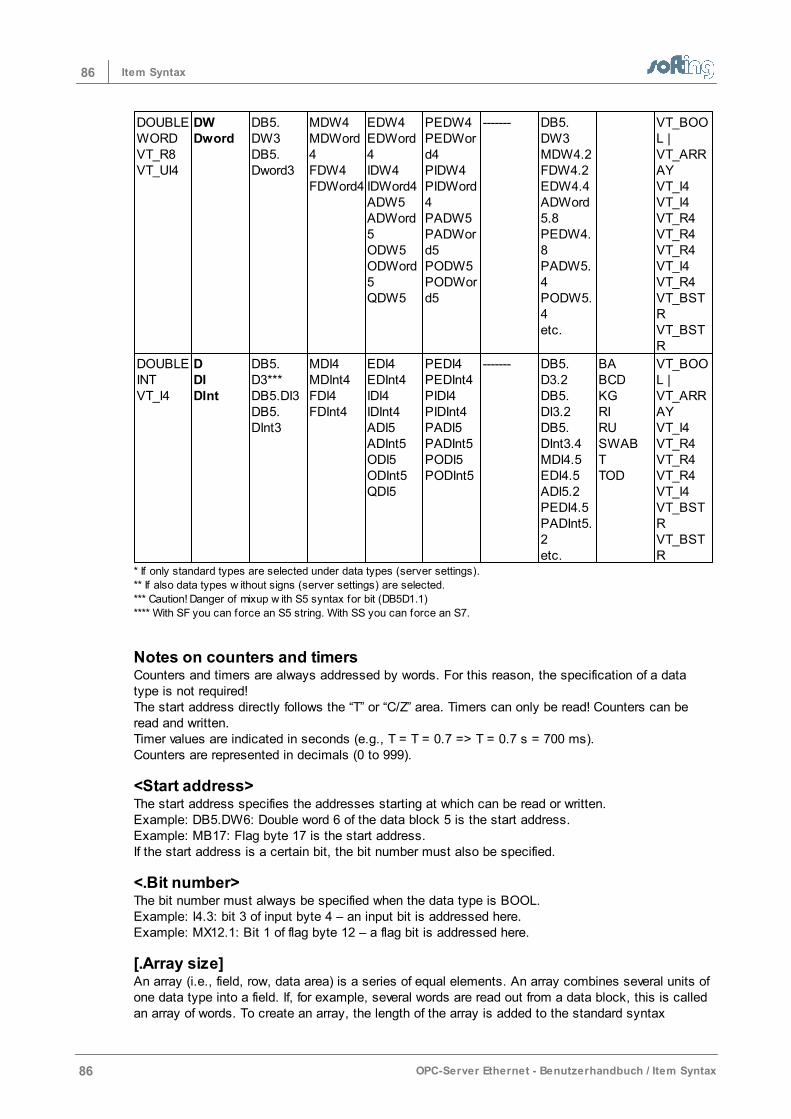
86 Item Syntax
86 OPC-Server Ethernet - Benutzerhandbuch / Item Syntax
DOUBLEWORDVT_R8VT_UI4
DWDword
DB5.DW3DB5.Dword3
MDW4MDWord4FDW4FDWord4
EDW4EDWord4IDW4IDWord4ADW5ADWord5ODW5ODWord5QDW5
PEDW4PEDWord4PIDW4PIDWord4PADW5PADWord5PODW5PODWord5
------- DB5.DW3MDW4.2FDW4.2EDW4.4ADWord5.8PEDW4.8PADW5.4PODW5.4etc.
VT_BOOL |VT_ARRAYVT_I4VT_I4VT_R4VT_R4VT_R4VT_I4VT_R4VT_BSTRVT_BSTR
DOUBLEINTVT_I4
DDIDInt
DB5.D3***DB5.DI3DB5.DInt3
MDI4MDInt4FDI4FDInt4
EDI4EDInt4IDI4IDInt4ADI5ADInt5ODI5ODInt5QDI5
PEDI4PEDInt4PIDI4PIDInt4PADI5PADInt5PODI5PODInt5
------- DB5.D3.2DB5.DI3.2DB5.DInt3.4MDI4.5EDI4.5ADI5.2PEDI4.5PADInt5.2etc.
BABCDKGRIRUSWABTTOD
VT_BOOL |VT_ARRAYVT_I4VT_R4VT_R4VT_R4VT_I4VT_BSTRVT_BSTR
* If only standard types are selected under data types (server settings).
** If also data types w ithout signs (server settings) are selected.
*** Caution! Danger of mixup w ith S5 syntax for bit (DB5D1.1)
**** With SF you can force an S5 string. With SS you can force an S7.
Notes on counters and timersCounters and timers are always addressed by words. For this reason, the specification of a datatype is not required! The start address directly follows the “T” or “C/Z” area. Timers can only be read! Counters can beread and written.Timer values are indicated in seconds (e.g., T = T = 0.7 => T = 0.7 s = 700 ms).Counters are represented in decimals (0 to 999).
<Start address>The start address specifies the addresses starting at which can be read or written.Example: DB5.DW6: Double word 6 of the data block 5 is the start address. Example: MB17: Flag byte 17 is the start address. If the start address is a certain bit, the bit number must also be specified.
<.Bit number>The bit number must always be specified when the data type is BOOL. Example: I4.3: bit 3 of input byte 4 – an input bit is addressed here.Example: MX12.1: Bit 1 of flag byte 12 – a flag bit is addressed here.
[.Array size]An array (i.e., field, row, data area) is a series of equal elements. An array combines several units ofone data type into a field. If, for example, several words are read out from a data block, this is calledan array of words. To create an array, the length of the array is added to the standard syntax

87Item Syntax
OPC-Server Ethernet - Benutzerhandbuch / Item Syntax 87
separated by a dot.Example: DB10.REAL2.5.For more information on arrays, go to here.
[Suffix]A value can be represented in another format with the aid of a suffix. For more information onsuffixes, go to here.
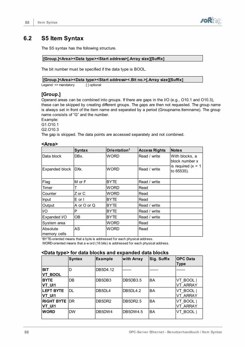
88 Item Syntax
88 OPC-Server Ethernet - Benutzerhandbuch / Item Syntax
6.2 S5 Item Syntax
The S5 syntax has the following structure.
[Group.]<Area><Data type><Start address>[.Array size][Suffix]
The bit number must be specified if the data type is BOOL.
[Group.]<Area><Data type><Start address><.Bit no.>[.Array size][Suffix]Legend: <> mandatory [ ] optional
[Group.]Operand areas can be combined into groups. If there are gaps in the I/O (e.g., O10.1 and O10.3),these can be skipped by creating different groups. The gaps are then not requested. The group nameis always set in front of the item name and separated by a period (Groupname.Itemname). The groupname consists of “G” and the number.Example: G1.O10.1G2.O10.3The gap is skipped. The data points are accessed separately and not combined.
<Area>Syntax Orientation1 Access Rights Notes
Data block DBx. WORD Read / write With blocks, ablock number xis required (x = 1to 65535).
Expanded block DXx. WORD Read / write
Flag M or F BYTE Read / write
Timer T WORD Read
Counter Z or C WORD Read
Input E or I BYTE Read
Output A or O or Q BYTE Read / write
I/O P BYTE Read / write
Expanded I/O OB BYTE Read / write
System area WORD Read
Absolutememory cells
AS WORD Read
1BYTE-oriented means that a byte is addressed for each physical address.
WORD-oriented means that a w ord (16 bits) is addressed for each physical address.
<Data type> for data blocks and expanded data blocks Syntax Example with Array Sig. Suffix OPC Data
Type
BITVT_BOOL
D DB5D4.12 ------- ------- -------
BYTEVT_UI1
DB DB5DB3 DB5DB3.5 BA VT_BOOL |VT_ARRAY
LEFT BYTEVT_UI1
DL DB5DL4 DB5DL4.2 BA VT_BOOL |VT_ARRAY
RIGHT BYTEVT_UI1
DR DB5DR2 DB5DR2.5 BA VT_BOOL |VT_ARRAY
WORD DW DB5DW4 DB5DW4.5 BA VT_BOOL |
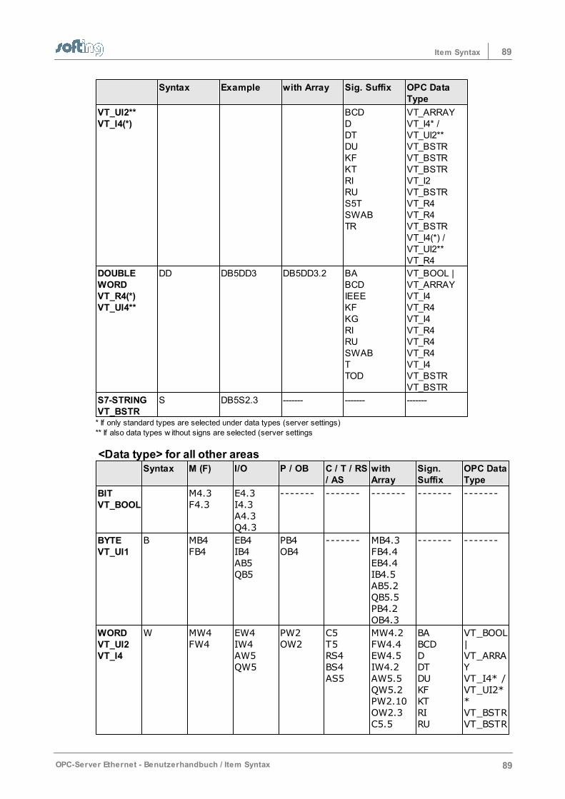
89Item Syntax
OPC-Server Ethernet - Benutzerhandbuch / Item Syntax 89
Syntax Example with Array Sig. Suffix OPC DataType
VT_UI2**VT_I4(*)
BCDDDTDUKFKTRIRUS5TSWABTR
VT_ARRAYVT_I4* /VT_UI2**VT_BSTRVT_BSTRVT_BSTRVT_I2VT_BSTRVT_R4VT_R4VT_BSTRVT_I4(*) /VT_UI2**VT_R4
DOUBLEWORDVT_R4(*)VT_UI4**
DD DB5DD3 DB5DD3.2 BABCDIEEEKFKGRIRUSWABTTOD
VT_BOOL |VT_ARRAYVT_I4VT_R4VT_I4VT_R4VT_R4VT_R4VT_I4VT_BSTRVT_BSTR
S7-STRINGVT_BSTR
S DB5S2.3 ------- -------
-------
* If only standard types are selected under data types (server settings)
** If also data types w ithout signs are selected (server settings
<Data type> for all other areas Syntax M (F) I/O P / OB C / T / RS
/ ASwithArray
Sign.Suffix
OPC DataType
BITVT_BOOL
M4.3F4.3
E4.3I4.3A4.3Q4.3
------- ------- ------- ------- -------
BYTEVT_UI1
B MB4FB4
EB4IB4AB5QB5
PB4OB4
------- MB4.3FB4.4EB4.4IB4.5AB5.2QB5.5PB4.2OB4.3
------- -------
WORDVT_UI2VT_I4
W MW4FW4
EW4IW4AW5QW5
PW2OW2
C5T5RS4BS4AS5
MW4.2FW4.4EW4.5IW4.2AW5.5QW5.2PW2.10OW2.3C5.5
BABCDDDTDUKFKTRIRU
VT_BOOL|VT_ARRAYVT_I4* /VT_UI2**VT_BSTRVT_BSTR
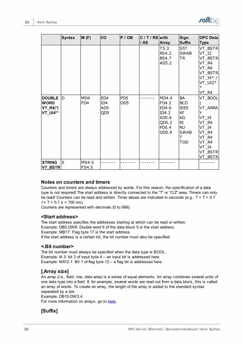
90 Item Syntax
90 OPC-Server Ethernet - Benutzerhandbuch / Item Syntax
Syntax M (F) I/O P / OB C / T / RS/ AS
withArray
Sign.Suffix
OPC DataType
T5.3RS4.2BS4.7AS5.2
S5TSWABTR
VT_BSTRVT_I2VT_BSTRVT_R4VT_R4VT_BSTRVT_I4* /VT_UI2**VT_R4
DOUBLEWORDVT_R4(*)VT_UI4**
D MD4FD4
ED4ID4AD5QD5
PD5OD5
-------
MD4.4FD4.2ED4.6ID4.2AD5.6QD5.2PD5.4OD5.9
BABCDIEEEKFKGRIRUSWABTTOD
VT_BOOL|VT_ARRAYVT_I4VT_R4VT_I4VT_R4VT_R4VT_R4VT_I4VT_BSTRVT_BSTR
STRINGVT_BSTR
S MS4.5FS4.5
------- ------- ------- ------- -------
Notes on counters and timersCounters and timers are always addressed by words. For this reason, the specification of a datatype is not required! The start address is directly connected to the “T” or “C/Z” area. Timers can onlybe read! Counters can be read and written. Timer values are indicated in seconds (e.g., T = T = 0.7=> T = 0.7 s = 700 ms).Counters are represented with decimals (0 to 999).
<Start address>The start address specifies the addresses starting at which can be read or written.Example: DB5.DW6: Double word 6 of the data block 5 is the start address. Example: MB17: Flag byte 17 is the start address. If the start address is a certain bit, the bit number must also be specified.
<.Bit number>The bit number must always be specified when the data type is BOOL. Example: I4.3: bit 3 of input byte 4 – an input bit is addressed here.Example: MX12.1: Bit 1 of flag byte 12 – a flag bit is addressed here.
[.Array size]An array (i.e., field, row, data area) is a series of equal elements. An array combines several units ofone data type into a field. If, for example, several words are read out from a data block, this is calledan array of words. To create an array, the length of the array is added to the standard syntaxseparated by a dot.Example: DB10.DW3.4For more information on arrays, go to here.
[Suffix]

91Item Syntax
OPC-Server Ethernet - Benutzerhandbuch / Item Syntax 91
A value can be represented in another format with the aid of a suffix. The S5 syntax without suffix adata type without a sign. A data type with a sign requires a suffix. Example: DB10DW3.4BCD.For more information on suffixes, go to here.
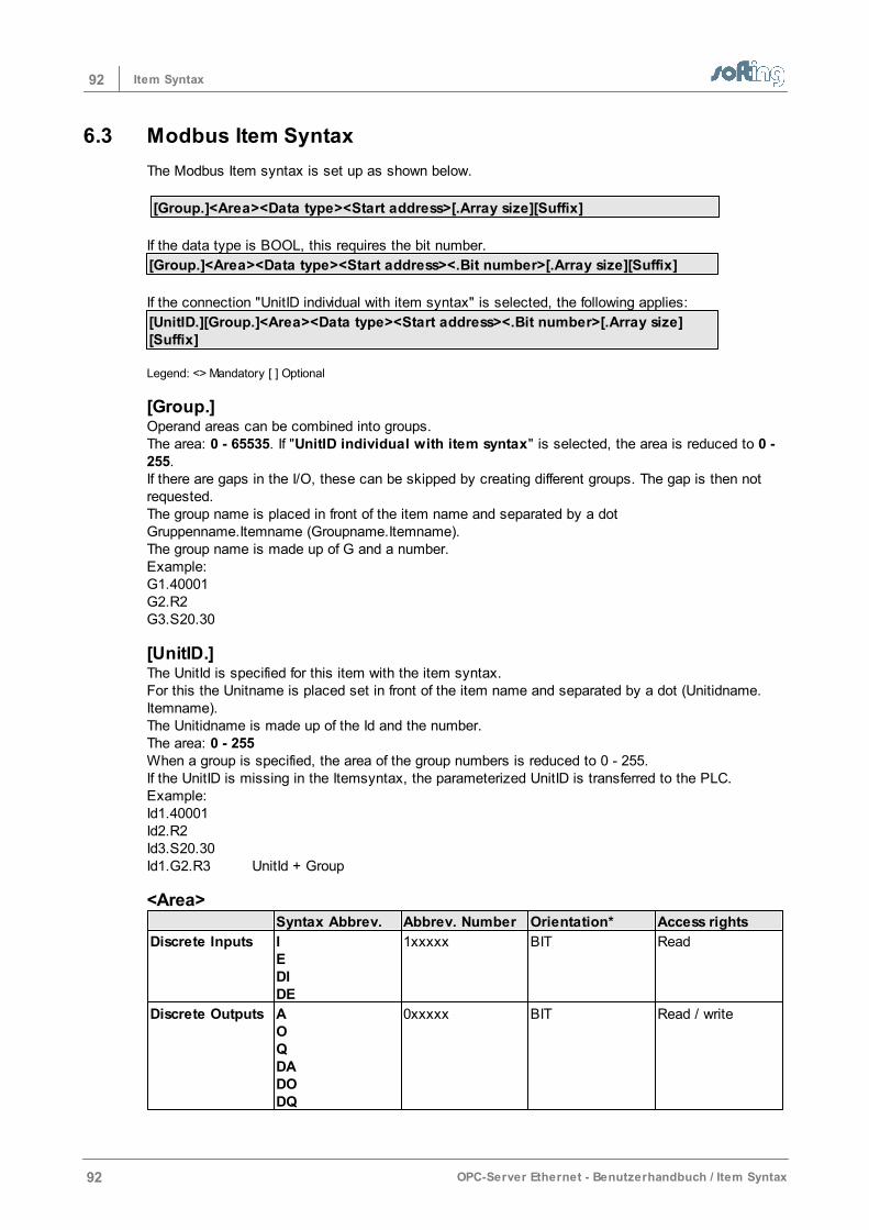
92 Item Syntax
92 OPC-Server Ethernet - Benutzerhandbuch / Item Syntax
6.3 Modbus Item Syntax
The Modbus Item syntax is set up as shown below.
[Group.]<Area><Data type><Start address>[.Array size][Suffix]
If the data type is BOOL, this requires the bit number.
[Group.]<Area><Data type><Start address><.Bit number>[.Array size][Suffix]
If the connection "UnitID individual with item syntax" is selected, the following applies:
[UnitID.][Group.]<Area><Data type><Start address><.Bit number>[.Array size][Suffix]
Legend: <> Mandatory [ ] Optional
[Group.]Operand areas can be combined into groups. The area: 0 - 65535. If "UnitID individual with item syntax" is selected, the area is reduced to 0 -255.If there are gaps in the I/O, these can be skipped by creating different groups. The gap is then notrequested. The group name is placed in front of the item name and separated by a dot Gruppenname.Itemname (Groupname.Itemname). The group name is made up of G and a number. Example:G1.40001G2.R2G3.S20.30
[UnitID.]The UnitId is specified for this item with the item syntax. For this the Unitname is placed set in front of the item name and separated by a dot (Unitidname.Itemname).The Unitidname is made up of the Id and the number.The area: 0 - 255When a group is specified, the area of the group numbers is reduced to 0 - 255.If the UnitID is missing in the Itemsyntax, the parameterized UnitID is transferred to the PLC. Example:Id1.40001Id2.R2Id3.S20.30Id1.G2.R3 UnitId + Group
<Area>Syntax Abbrev. Abbrev. Number Orientation* Access rights
Discrete Inputs IEDIDE
1xxxxx BIT Read
Discrete Outputs AOQDADODQ
0xxxxx BIT Read / write
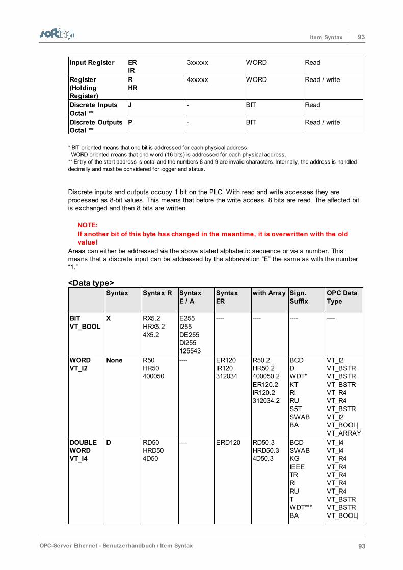
93Item Syntax
OPC-Server Ethernet - Benutzerhandbuch / Item Syntax 93
Input Register ERIR
3xxxxx WORD Read
Register(HoldingRegister)
RHR
4xxxxx WORD Read / write
Discrete InputsOctal **
J - BIT Read
Discrete OutputsOctal **
P - BIT Read / write
* BIT-oriented means that one bit is addressed for each physical address.
WORD-oriented means that one w ord (16 bits) is addressed for each physical address.
** Entry of the start address is octal and the numbers 8 and 9 are invalid characters. Internally, the address is handled
decimally and must be considered for logger and status.
Discrete inputs and outputs occupy 1 bit on the PLC. With read and write accesses they areprocessed as 8-bit values. This means that before the write access, 8 bits are read. The affected bitis exchanged and then 8 bits are written.
NOTE:
If another bit of this byte has changed in the meantime, it is overwritten with the oldvalue!
Areas can either be addressed via the above stated alphabetic sequence or via a number. Thismeans that a discrete input can be addressed by the abbreviation “E” the same as with the number“1.”
<Data type> Syntax Syntax R Syntax
E / ASyntaxER
with Array Sign.Suffix
OPC DataType
BITVT_BOOL
X RX5.2HRX5.24X5.2
E255I255DE255DI255125543
---- ---- ---- ----
WORDVT_I2
None R50HR50400050
---- ER120IR120312034
R50.2HR50.2400050.2ER120.2IR120.2312034.2
BCDDWDT*KTRIRUS5TSWABBA
VT_I2VT_BSTRVT_BSTRVT_BSTRVT_R4VT_R4VT_BSTRVT_I2VT_BOOL|VT_ARRAY
DOUBLEWORDVT_I4
D RD50HRD504D50
---- ERD120 RD50.3HRD50.34D50.3
BCDSWABKGIEEETRRIRUTWDT***BA
VT_I4VT_I4VT_R4VT_R4VT_R4VT_R4VT_R4VT_BSTRVT_BSTRVT_BOOL|
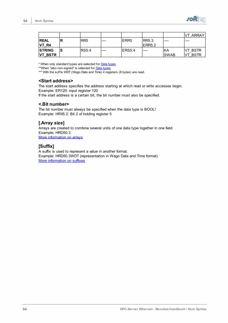
94 Item Syntax
94 OPC-Server Ethernet - Benutzerhandbuch / Item Syntax
VT_ARRAY
REALVT_R4
R RR5 ---- ERR5 RR5.3ERR5.2
---- ----
STRINGVT_BSTR
S RS5.4 ---- ERS5.4 ---- KASWAB
VT_BSTRVT_BSTR
* When only standard types are selected for Data types
**When "also non-signed" is selected for Data types
*** With the suff ix WDT (Wago Date and Time) 4 registers (8 bytes) are read.
<Start address>The start address specifies the address starting at which read or write accesses begin.Example: ER120: input register 120If the start address is a certain bit, the bit number must also be specified.
<.Bit number>The bit number must always be specified when the data type is BOOL!Example: HRX5.2: Bit 2 of holding register 5
[.Array size]Arrays are created to combine several units of one data type together in one field. Example: HRD50.3More information on arrays
[Suffix]A suffix is used to represent a value in another format. Example: HRD50.3WDT (representation in Wago Date and Time format) More information on suffixes
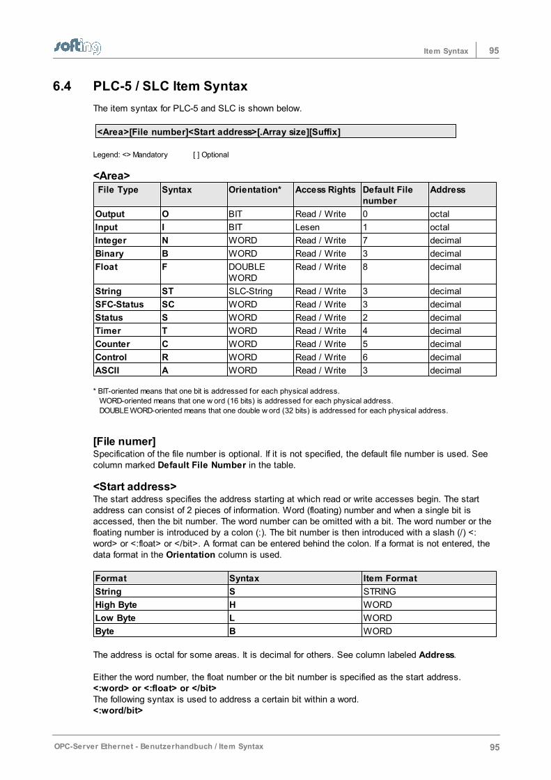
95Item Syntax
OPC-Server Ethernet - Benutzerhandbuch / Item Syntax 95
6.4 PLC-5 / SLC Item Syntax
The item syntax for PLC-5 and SLC is shown below.
<Area>[File number]<Start address>[.Array size][Suffix]
Legend: <> Mandatory [ ] Optional
<Area> File Type Syntax Orientation* Access Rights Default File
numberAddress
Output O BIT Read / Write 0 octal
Input I BIT Lesen 1 octal
Integer N WORD Read / Write 7 decimal
Binary B WORD Read / Write 3 decimal
Float F DOUBLEWORD
Read / Write 8 decimal
String ST SLC-String Read / Write 3 decimal
SFC-Status SC WORD Read / Write 3 decimal
Status S WORD Read / Write 2 decimal
Timer T WORD Read / Write 4 decimal
Counter C WORD Read / Write 5 decimal
Control R WORD Read / Write 6 decimal
ASCII A WORD Read / Write 3 decimal * BIT-oriented means that one bit is addressed for each physical address.
WORD-oriented means that one w ord (16 bits) is addressed for each physical address.
DOUBLE WORD-oriented means that one double w ord (32 bits) is addressed for each physical address.
[File numer]Specification of the file number is optional. If it is not specified, the default file number is used. Seecolumn marked Default File Number in the table.
<Start address>The start address specifies the address starting at which read or write accesses begin. The startaddress can consist of 2 pieces of information. Word (floating) number and when a single bit isaccessed, then the bit number. The word number can be omitted with a bit. The word number or thefloating number is introduced by a colon (:). The bit number is then introduced with a slash (/) <:word> or <:float> or </bit>. A format can be entered behind the colon. If a format is not entered, thedata format in the Orientation column is used.
Format Syntax Item Format
String S STRING
High Byte H WORD
Low Byte L WORD
Byte B WORD
The address is octal for some areas. It is decimal for others. See column labeled Address. Either the word number, the float number or the bit number is specified as the start address. <:word> or <:float> or </bit>The following syntax is used to address a certain bit within a word. <:word/bit>
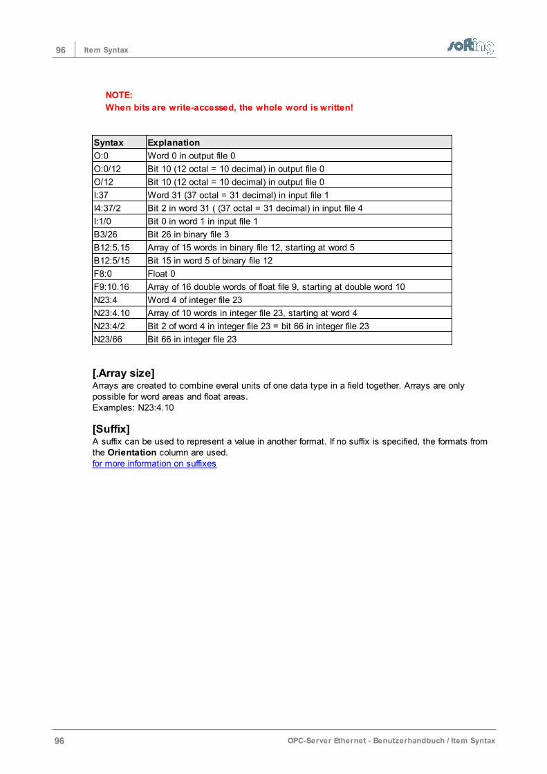
96 Item Syntax
96 OPC-Server Ethernet - Benutzerhandbuch / Item Syntax
NOTE:
When bits are write-accessed, the whole word is written!
Syntax Explanation
O:0 Word 0 in output file 0
O:0/12 Bit 10 (12 octal = 10 decimal) in output file 0
O/12 Bit 10 (12 octal = 10 decimal) in output file 0
I:37 Word 31 (37 octal = 31 decimal) in input file 1
I4:37/2 Bit 2 in word 31 ( (37 octal = 31 decimal) in input file 4
I:1/0 Bit 0 in word 1 in input file 1
B3/26 Bit 26 in binary file 3
B12:5.15 Array of 15 words in binary file 12, starting at word 5
B12:5/15 Bit 15 in word 5 of binary file 12
F8:0 Float 0
F9:10.16 Array of 16 double words of float file 9, starting at double word 10
N23:4 Word 4 of integer file 23
N23:4.10 Array of 10 words in integer file 23, starting at word 4
N23:4/2 Bit 2 of word 4 in integer file 23 = bit 66 in integer file 23
N23/66 Bit 66 in integer file 23
[.Array size]Arrays are created to combine everal units of one data type in a field together. Arrays are onlypossible for word areas and float areas. Examples: N23:4.10
[Suffix]A suffix can be used to represent a value in another format. If no suffix is specified, the formats fromthe Orientation column are used.for more information on suffixes
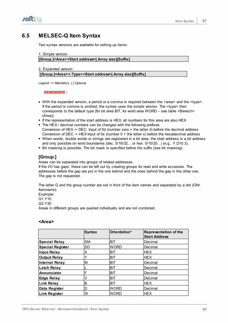
97Item Syntax
OPC-Server Ethernet - Benutzerhandbuch / Item Syntax 97
6.5 MELSEC-Q Item Syntax
Two syntax versions are available for setting up items. 1. Simple version:
[Group.]<Area><Start address>[.Array size][Suffix]
2. Expanded version:
[Group.]<Area><.Type><Start address>[.Array size][Suffix]
Legend: <> Mandatory [ ] Optional
REMEMBER :
With the expanded version, a period or a comma is required between the <area> and the <type>.If the period or comma is omitted, the syntax uses the simple version. The <type> thencorresponds to the default type (for bit area BIT, for word area WORD – see table <Bereich>(Area)). If the representation of the start address is HEX, all numbers for this area are also HEX. The HEX / decimal numbers can be changed with the following prefixes. Conversion of HEX -> DEC: Input of 0d (number zero + the letter d) before the decimal address Conversion of DEC -> HEX Input of 0x (number 0 + the letter x) before the hexadecimal addressWhen words, double words or strings are registered in a bit area, the start address is a bit addressand only possible on word boundaries (dec. 0/16/32... or hex: 0/10/20...) (e.g., Y.D10.3).Bit masking is possible. The bit mask is specified before the suffix (see bit masking).
[Group.]Areas can be separated into groups of related addresses.If the I/O has gaps, these can be left out by creating groups for read and write accesses. Theaddresses before the gap are put in the one behind and the ones behind the gap in the other one.The gap is not requested.
The letter G and the group number are set in front of the item names and separated by a dot (GNr.Itemname).Example:G1.Y10G2.Y30Areas in different groups are queried individually and are not combined.
<Area>
Syntax Orientation* Representation of theStart Address
Special Relay SM BIT Decimal
Special Register SD WORD Decimal
Input Relay X BIT HEX
Output Relay Y BIT HEX
Internal Relay M BIT Decimal
Latch Relay L BIT Decimal
Annunciator F BIT Decimal
Edge Relay V BIT Decimal
Link Relay B BIT HEX
Data Register D WORD Decimal
Link Register W WORD HEX
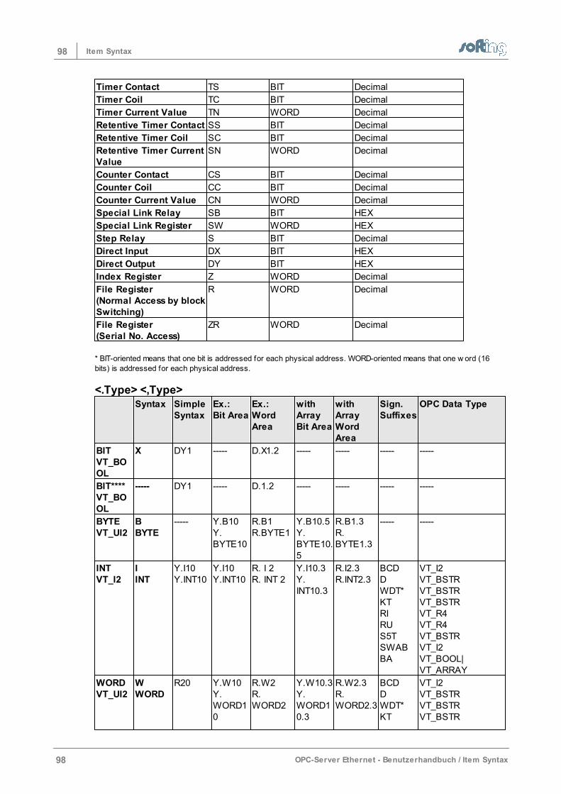
98 Item Syntax
98 OPC-Server Ethernet - Benutzerhandbuch / Item Syntax
Timer Contact TS BIT Decimal
Timer Coil TC BIT Decimal
Timer Current Value TN WORD Decimal
Retentive Timer Contact SS BIT Decimal
Retentive Timer Coil SC BIT Decimal
Retentive Timer CurrentValue
SN WORD Decimal
Counter Contact CS BIT Decimal
Counter Coil CC BIT Decimal
Counter Current Value CN WORD Decimal
Special Link Relay SB BIT HEX
Special Link Register SW WORD HEX
Step Relay S BIT Decimal
Direct Input DX BIT HEX
Direct Output DY BIT HEX
Index Register Z WORD Decimal
File Register(Normal Access by blockSwitching)
R WORD Decimal
File Register(Serial No. Access)
ZR WORD Decimal
* BIT-oriented means that one bit is addressed for each physical address. WORD-oriented means that one w ord (16
bits) is addressed for each physical address.
<.Type> <,Type> Syntax Simple
SyntaxEx.:Bit Area
Ex.:WordArea
withArray Bit Area
withArray WordArea
Sign.Suffixes
OPC Data Type
BITVT_BOOL
X DY1 ----- D.X1.2 ----- ----- ----- -----
BIT****VT_BOOL
-----
DY1 ----- D.1.2 ----- ----- ----- -----
BYTEVT_UI2
BBYTE
----- Y.B10Y.BYTE10
R.B1R.BYTE1
Y.B10.5Y.BYTE10.5
R.B1.3R.BYTE1.3
----- -----
INTVT_I2
IINT
Y.I10Y.INT10
Y.I10Y.INT10
R. I 2R. INT 2
Y.I10.3Y.INT10.3
R.I2.3 R.INT2.3
BCDDWDT*KTRIRUS5TSWABBA
VT_I2VT_BSTRVT_BSTRVT_BSTRVT_R4VT_R4VT_BSTRVT_I2VT_BOOL|VT_ARRAY
WORDVT_UI2
WWORD
R20 Y.W10Y.WORD10
R.W2R.WORD2
Y.W10.3Y.WORD10.3
R.W2.3 R.WORD2.3
BCDDWDT*KT
VT_I2VT_BSTRVT_BSTRVT_BSTR
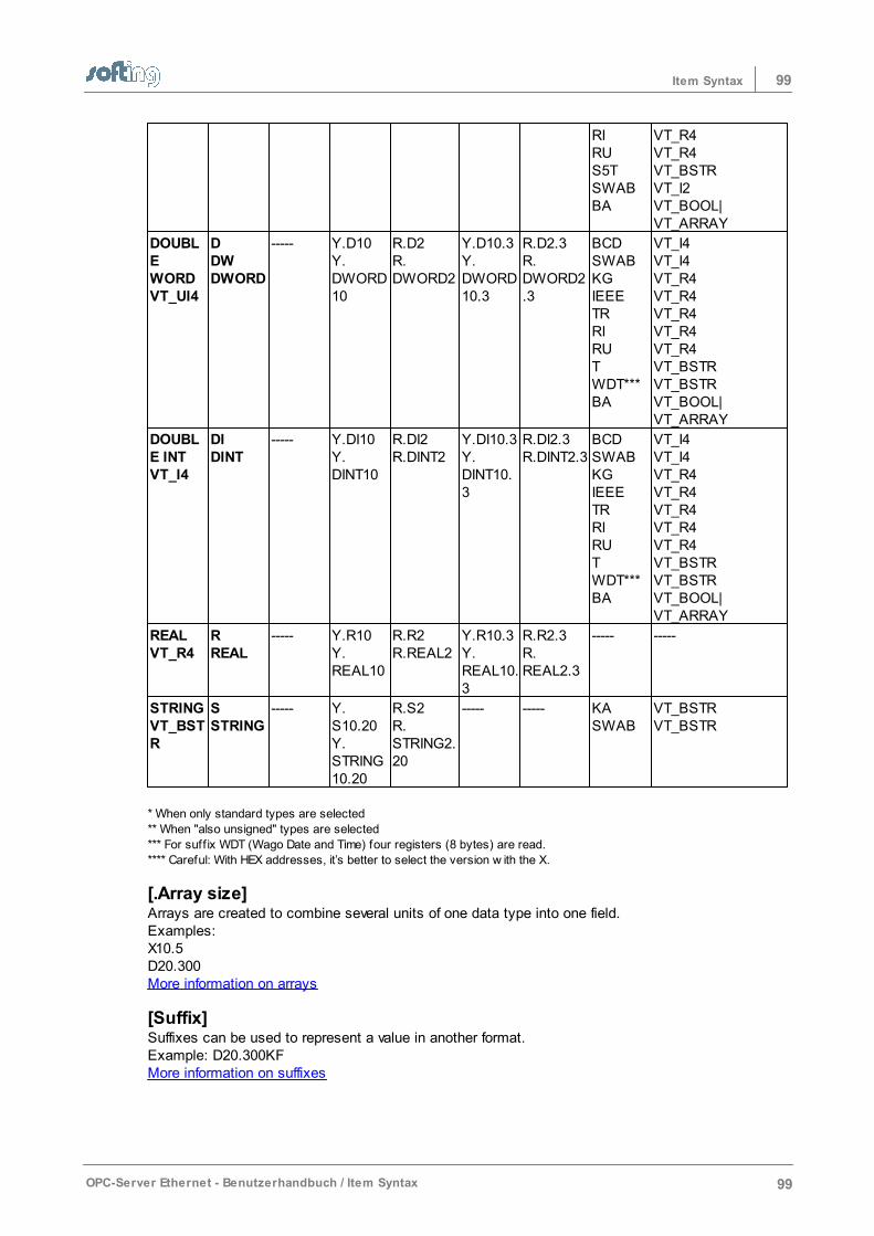
99Item Syntax
OPC-Server Ethernet - Benutzerhandbuch / Item Syntax 99
RIRUS5TSWABBA
VT_R4VT_R4VT_BSTRVT_I2VT_BOOL|VT_ARRAY
DOUBLEWORDVT_UI4
DDWDWORD
----- Y.D10Y.DWORD10
R.D2R.DWORD2
Y.D10.3Y.DWORD10.3
R.D2.3R.DWORD2.3
BCDSWABKGIEEETRRIRUTWDT***BA
VT_I4VT_I4VT_R4VT_R4VT_R4VT_R4VT_R4VT_BSTRVT_BSTRVT_BOOL|VT_ARRAY
DOUBLE INTVT_I4
DIDINT
----- Y.DI10Y.DINT10
R.DI2R.DINT2
Y.DI10.3Y.DINT10.3
R.DI2.3R.DINT2.3
BCDSWABKGIEEETRRIRUTWDT***BA
VT_I4VT_I4VT_R4VT_R4VT_R4VT_R4VT_R4VT_BSTRVT_BSTRVT_BOOL|VT_ARRAY
REALVT_R4
RREAL
----- Y.R10Y.REAL10
R.R2R.REAL2
Y.R10.3Y.REAL10.3
R.R2.3R.REAL2.3
----- -----
STRINGVT_BSTR
SSTRING
----- Y.S10.20Y.STRING10.20
R.S2R.STRING2.20
----- ----- KASWAB
VT_BSTRVT_BSTR
* When only standard types are selected
** When "also unsigned" types are selected
*** For suff ix WDT (Wago Date and Time) four registers (8 bytes) are read.
**** Careful: With HEX addresses, it’s better to select the version w ith the X.
[.Array size]Arrays are created to combine several units of one data type into one field. Examples:X10.5D20.300More information on arrays
[Suffix]Suffixes can be used to represent a value in another format. Example: D20.300KF More information on suffixes
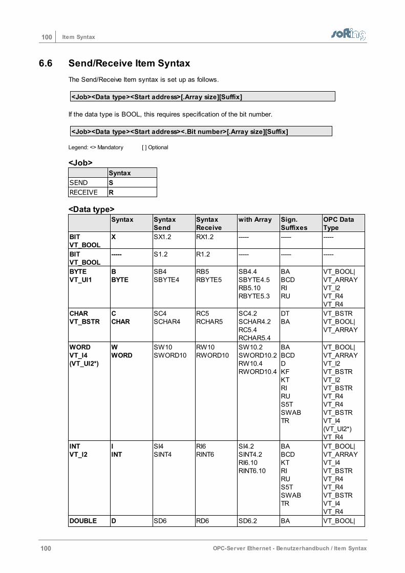
100 Item Syntax
100 OPC-Server Ethernet - Benutzerhandbuch / Item Syntax
6.6 Send/Receive Item Syntax
The Send/Receive Item syntax is set up as follows.
<Job><Data type><Start address>[.Array size][Suffix]
If the data type is BOOL, this requires specification of the bit number.
<Job><Data type><Start address><.Bit number>[.Array size][Suffix]
Legend: <> Mandatory [ ] Optional
<Job> Syntax
SEND S
RECEIVE R
<Data type> Syntax Syntax
SendSyntaxReceive
with Array Sign.Suffixes
OPC DataType
BITVT_BOOL
X SX1.2 RX1.2 -----
-----
-----
BITVT_BOOL
-----
S1.2 R1.2 -----
-----
-----
BYTEVT_UI1
BBYTE
SB4SBYTE4
RB5RBYTE5
SB4.4SBYTE4.5RB5.10RBYTE5.3
BABCDRIRU
VT_BOOL|VT_ARRAYVT_I2VT_R4VT_R4
CHARVT_BSTR
CCHAR
SC4SCHAR4
RC5RCHAR5
SC4.2SCHAR4.2RC5.4RCHAR5.4
DTBA
VT_BSTRVT_BOOL|VT_ARRAY
WORDVT_I4(VT_UI2*)
WWORD
SW10SWORD10
RW10RWORD10
SW10.2SWORD10.2RW10.4RWORD10.4
BABCDDKFKTRIRUS5TSWABTR
VT_BOOL|VT_ARRAYVT_I2VT_BSTRVT_I2VT_BSTRVT_R4VT_R4VT_BSTRVT_I4(VT_UI2*)VT_R4
INTVT_I2
IINT
SI4SINT4
RI6RINT6
SI4.2SINT4.2RI6.10RINT6.10
BABCDKTRIRUS5TSWABTR
VT_BOOL|VT_ARRAYVT_I4VT_BSTRVT_R4VT_R4VT_BSTRVT_I4VT_R4
DOUBLE D SD6 RD6 SD6.2 BA VT_BOOL|
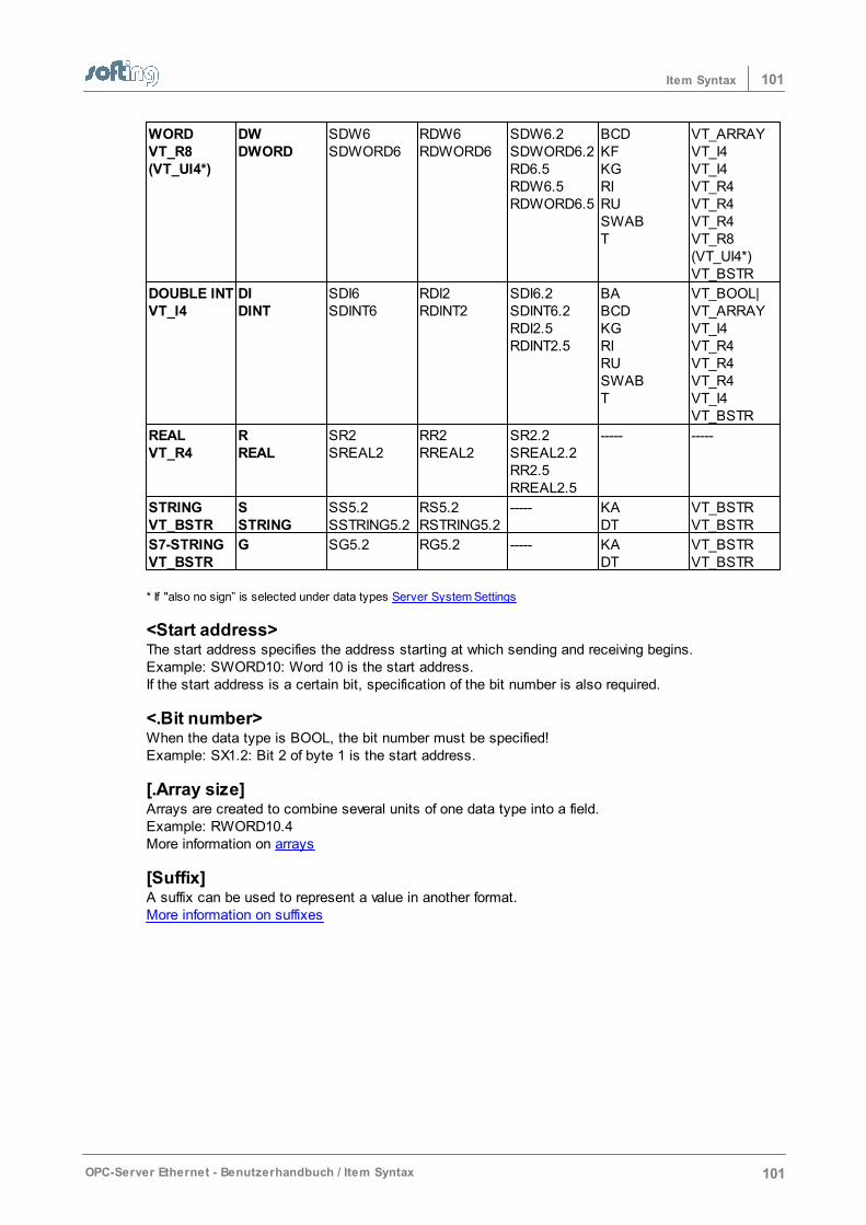
101Item Syntax
OPC-Server Ethernet - Benutzerhandbuch / Item Syntax 101
WORDVT_R8(VT_UI4*)
DWDWORD
SDW6SDWORD6
RDW6RDWORD6
SDW6.2SDWORD6.2RD6.5RDW6.5RDWORD6.5
BCDKFKGRIRUSWABT
VT_ARRAYVT_I4VT_I4VT_R4VT_R4VT_R4VT_R8(VT_UI4*)VT_BSTR
DOUBLE INTVT_I4
DIDINT
SDI6SDINT6
RDI2RDINT2
SDI6.2SDINT6.2RDI2.5RDINT2.5
BABCDKGRIRUSWABT
VT_BOOL|VT_ARRAYVT_I4VT_R4VT_R4VT_R4VT_I4VT_BSTR
REALVT_R4
RREAL
SR2SREAL2
RR2RREAL2
SR2.2SREAL2.2RR2.5RREAL2.5
-----
-----
STRINGVT_BSTR
SSTRING
SS5.2SSTRING5.2
RS5.2RSTRING5.2
-----
KADT
VT_BSTRVT_BSTR
S7-STRINGVT_BSTR
G SG5.2 RG5.2 -----
KADT
VT_BSTRVT_BSTR
* If "also no sign” is selected under data types Server System Settings
<Start address>The start address specifies the address starting at which sending and receiving begins.Example: SWORD10: Word 10 is the start address. If the start address is a certain bit, specification of the bit number is also required.
<.Bit number>When the data type is BOOL, the bit number must be specified!Example: SX1.2: Bit 2 of byte 1 is the start address.
[.Array size]Arrays are created to combine several units of one data type into a field. Example: RWORD10.4More information on arrays
[Suffix]A suffix can be used to represent a value in another format. More information on suffixes
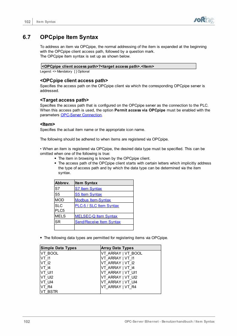
102 Item Syntax
102 OPC-Server Ethernet - Benutzerhandbuch / Item Syntax
6.7 OPCpipe Item Syntax
To address an item via OPCpipe, the normal addressing of the item is expanded at the beginningwith the OPCpipe client access path, followed by a question mark. The OPCpipe item syntax is set up as shown below.
<OPCpipe client access path>?<target access path>.<Item>Legend: <> Mandatory [ ] Optional
<OPCpipe client access path>Specifies the access path on the OPCpipe client via which the corresponding OPCpipe server isaddressed.
<Target access path>Specifies the access path that is configured on the OPCpipe server as the connection to the PLC.When this access path is used, the option Permit access via OPCpipe must be enabled with theparameters OPC-Server Connection.
<Item>Specifies the actual item name or the appropriate icon name.
The following should be adhered to when items are registered via OPCpipe.
• When an item is registered via OPCpipe, the desired data type must be specified. This can beomitted when one of the following is true:
The item in browsing is known by the OPCpipe client.The access path of the OPCpipe client starts with certain letters which implicitly addressthe type of access path and by which the data type can be determined via the itemsyntax.
Abbrev. Item Syntax
S7 S7 Item Syntax
S5 S5 Item Syntax
MOD Modbus Item-Syntax
SLCPLC5
PLC-5 / SLC Item Syntax
MELS MELSEC-Q Item Syntax
SR Send/Receive Item Syntax
The following data types are permitted for registering items via OPCpipe.
Simple Data Types Array Data Types
VT_BOOLVT_I1VT_I2VT_I4VT_UI1VT_UI2VT_UI4VT_R4VT_BSTR
VT_ARRAY | VT_BOOLVT_ARRAY | VT_I1VT_ARRAY | VT_I2VT_ARRAY | VT_I4VT_ARRAY | VT_UI1VT_ARRAY | VT_UI2VT_ARRAY | VT_UI4VT_ARRAY | VT_R4

103Item Syntax
OPC-Server Ethernet - Benutzerhandbuch / Item Syntax 103
6.8 Arrays
The word array means a series of equal elements (field, row, data area). An array combines severalunits of one data tpye in a field. To create an array, the length of the array is added to the standardsyntax, separated by a period.
Arrays are NOT possible for:
BOOLDATE AND TIMEDATETIMETIME OF DAYSTRINGS (is already an array of characters) as well as for all suffixes which are string or bool to the client:
BA (already an array of bits)KAS5TKTDTDTDUTOD
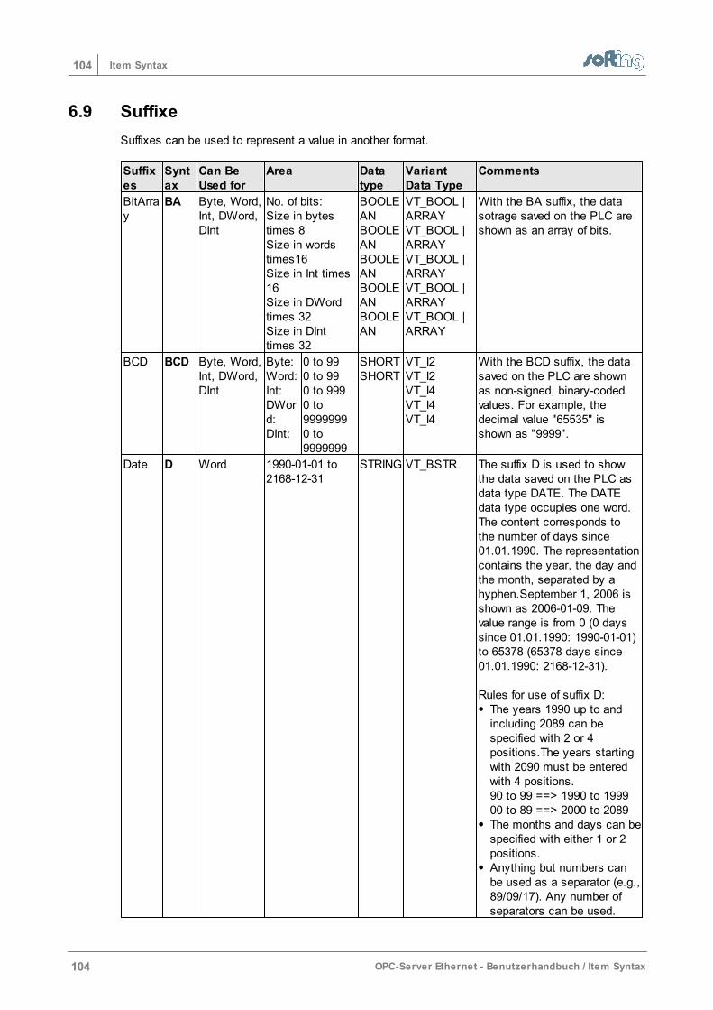
104 Item Syntax
104 OPC-Server Ethernet - Benutzerhandbuch / Item Syntax
6.9 Suffixe
Suffixes can be used to represent a value in another format.
Suffixes
Syntax
Can BeUsed for
Area Datatype
VariantData Type
Comments
BitArray
BA Byte, Word,Int, DWord,DInt
No. of bits:Size in bytestimes 8Size in wordstimes16Size in Int times16Size in DWordtimes 32Size in DInttimes 32
BOOLEANBOOLEANBOOLEANBOOLEANBOOLEAN
VT_BOOL |ARRAYVT_BOOL |ARRAYVT_BOOL |ARRAYVT_BOOL |ARRAYVT_BOOL |ARRAY
With the BA suffix, the datasotrage saved on the PLC areshown as an array of bits.
BCD BCD Byte, Word,Int, DWord,DInt
Byte:Word:Int:DWord:DInt:
0 to 990 to 990 to 9990 to99999990 to9999999
SHORTSHORT
VT_I2VT_I2VT_I4VT_I4VT_I4
With the BCD suffix, the datasaved on the PLC are shownas non-signed, binary-codedvalues. For example, thedecimal value "65535" isshown as "9999".
Date D Word 1990-01-01 to2168-12-31
STRING VT_BSTR The suffix D is used to show the data saved on the PLC asdata type DATE. The DATEdata type occupies one word.The content corresponds to the number of days since 01.01.1990. The representationcontains the year, the day andthe month, separated by ahyphen.September 1, 2006 isshown as 2006-01-09. Thevalue range is from 0 (0 days since 01.01.1990: 1990-01-01)to 65378 (65378 days since01.01.1990: 2168-12-31).
Rules for use of suffix D:The years 1990 up to andincluding 2089 can bespecified with 2 or 4positions.The years startingwith 2090 must be enteredwith 4 positions. 90 to 99 ==> 1990 to 1999 00 to 89 ==> 2000 to 2089The months and days can bespecified with either 1 or 2positions.Anything but numbers canbe used as a separator (e.g.,89/09/17). Any number ofseparators can be used.
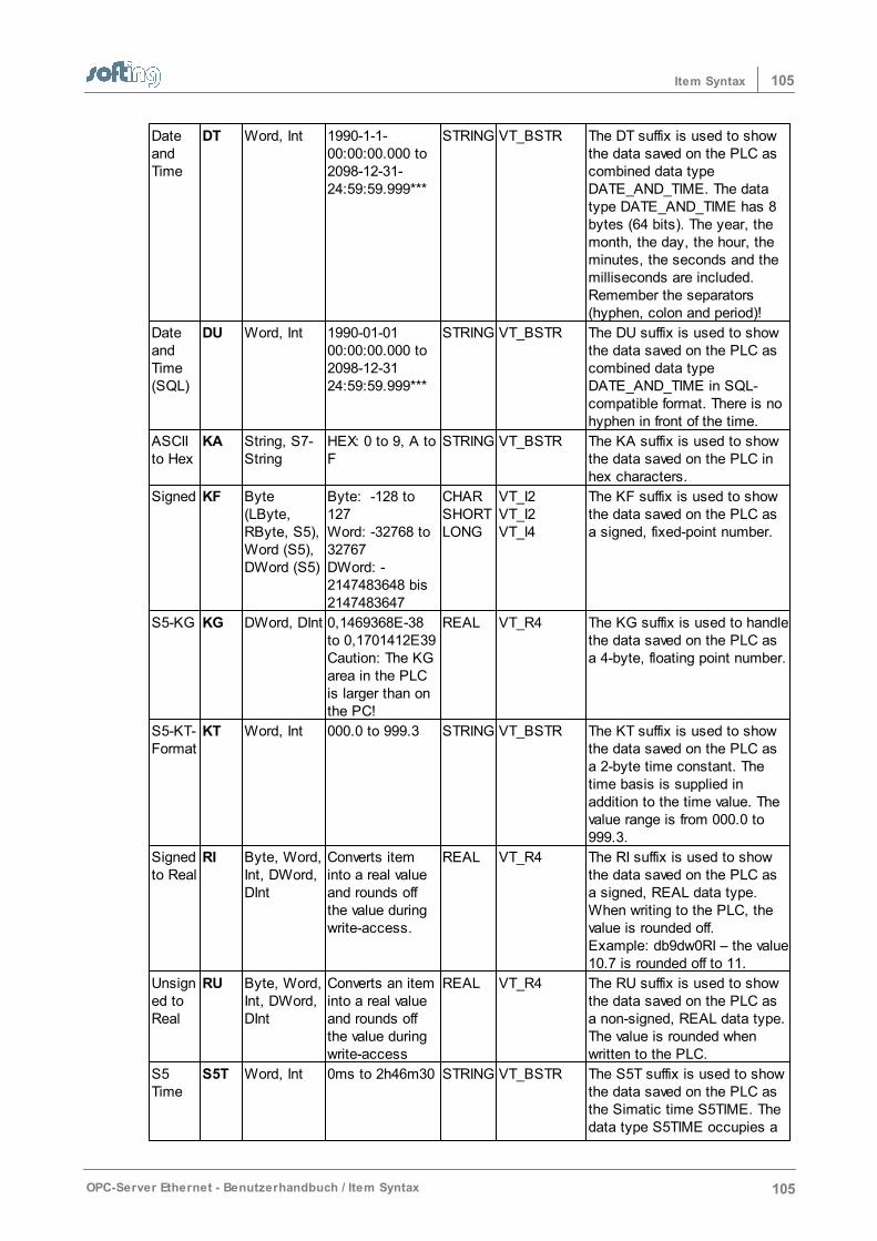
105Item Syntax
OPC-Server Ethernet - Benutzerhandbuch / Item Syntax 105
DateandTime
DT Word, Int 1990-1-1-00:00:00.000 to2098-12-31-24:59:59.999***
STRING VT_BSTR The DT suffix is used to showthe data saved on the PLC ascombined data typeDATE_AND_TIME. The datatype DATE_AND_TIME has 8bytes (64 bits). The year, themonth, the day, the hour, theminutes, the seconds and themilliseconds are included.Remember the separators(hyphen, colon and period)!
DateandTime(SQL)
DU Word, Int 1990-01-0100:00:00.000 to2098-12-3124:59:59.999***
STRING VT_BSTR The DU suffix is used to showthe data saved on the PLC ascombined data typeDATE_AND_TIME in SQL-compatible format. There is nohyphen in front of the time.
ASCIIto Hex
KA String, S7-String
HEX: 0 to 9, A toF
STRING VT_BSTR The KA suffix is used to showthe data saved on the PLC inhex characters.
Signed KF Byte(LByte,RByte, S5),Word (S5),DWord (S5)
Byte: -128 to127Word: -32768 to32767DWord: -2147483648 bis2147483647
CHARSHORTLONG
VT_I2VT_I2VT_I4
The KF suffix is used to showthe data saved on the PLC asa signed, fixed-point number.
S5-KG KG DWord, DInt 0,1469368E-38to 0,1701412E39Caution: The KGarea in the PLCis larger than onthe PC!
REAL VT_R4 The KG suffix is used to handlethe data saved on the PLC asa 4-byte, floating point number.
S5-KT-Format
KT Word, Int 000.0 to 999.3 STRING VT_BSTR The KT suffix is used to showthe data saved on the PLC asa 2-byte time constant. Thetime basis is supplied inaddition to the time value. Thevalue range is from 000.0 to999.3.
Signedto Real
RI Byte, Word,Int, DWord,DInt
Converts iteminto a real valueand rounds offthe value duringwrite-access.
REAL VT_R4 The RI suffix is used to showthe data saved on the PLC asa signed, REAL data type.When writing to the PLC, thevalue is rounded off. Example: db9dw0RI – the value10.7 is rounded off to 11.
Unsigned toReal
RU Byte, Word,Int, DWord,DInt
Converts an iteminto a real valueand rounds offthe value duringwrite-access
REAL VT_R4 The RU suffix is used to showthe data saved on the PLC asa non-signed, REAL data type.The value is rounded whenwritten to the PLC.
S5Time
S5T Word, Int 0ms to 2h46m30 STRING VT_BSTR The S5T suffix is used to showthe data saved on the PLC asthe Simatic time S5TIME. Thedata type S5TIME occupies a
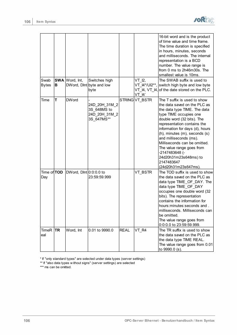
106 Item Syntax
106 OPC-Server Ethernet - Benutzerhandbuch / Item Syntax
16-bit word and is the productof time value and time frame.The time duration is specifiedin hours, minutes, secondsand milliseconds. The internalrepresentation is a BCDnumber. The value range isfrom 0 ms to 2h46m30s. Thesmallest value is 10ms.
SwabBytes
SWAB
Word, Int,DWord, DInt
Switches highbyte and lowbyte
VT_I2,VT_I4*/UI2**,VT_I4, VT_I4,VT_I4´
The SWAB suffix is used toswitch high byte and low byteof the date stored on the PLC.
Time T DWord -24D_20H_31M_23S_648MS to24D_20H_31M_23S_647MS**
STRING VT_BSTR The T suffix is used to showthe data saved on the PLC asthe data type TIME. The datatype TIME occupies onedouble word (32 bits). Therepresentation contains theinformation for days (d), hours(h), minutes (m), seconds (s)and milliseconds (ms).Milliseconds can be omitted.The value range goes from -2147483648 (-24d20h31m23s648ms) to2147483647(24d20h31m23s647ms).
Time ofDay
TOD DWord, DInt 0:0:0.0 to23:59:59.999
VT_BSTR The TOD suffix is used to showthe data saved on the PLC asdata type TIME_OF_DAY. Thedata type TIME_OF_DAYoccupies one double word (32bits). The representationcontains the information forhours:minutes:seconds and .milliseconds. Milliseconds canbe omitted.The value range goes from0:0:0.0 to 23:59:59.999.
TimeReal
TR Word, Int 0.01 to 9990.0 REAL VT_R4 The TR suffix is used to showthe data saved on the PLC asthe data type TIME REAL.The value range goes from 0.01to 9990.0 (s).
* If "only standard types" are selected under data types (server settings)
** If "also data types w ithout signs" (server settings) are selected
*** ms can be omitted.
107Item Syntax
OPC-Server Ethernet - Benutzerhandbuch / Item Syntax 107
6.10 Data Types
The representation of both unsigned data types VT_UI2 and VT_UI4 on the OPC interface can beset.
While data types such as BYTE, WORD or S5TIME are used by the PLC user programs, OPC usesso-called variant types. The data types from the PLC user program are mapped accordingly onvariance types. Each OPC item then has a canonical (i.e., its own) data type. The server providesthe items with a default data format. For example, the OPC item DB5W3 (S7 syntax) is mapped tothe variant type VT_I4. See the respective table for item syntax for which variant type the PLC datatypes are mapped.When OPC items are set up, the OPC client can assign each item with a desired data type. Whenthe data type EMPTY is specified, the default data format is used. When another format is selected,the server tries to convert the default format into the format desired by the client.
Only standard typesThis mode converts unsigned data types into the next greater signed data types. It should only beused when the OPC client does not support the unsigned data types VT_UI2 and VT_UI4.This mode is the default setting and can be used for most of the OPC clients. It is used when theclient does not support the unsigned data types VT_UI2 and VT_I4.
Also unsigned typesThis mode is the default setting. It is used when the OPC client supports the unsigned data typesVT_UI2 and VT_UI4. For which data types are affected, see the respective table for the item syntax.
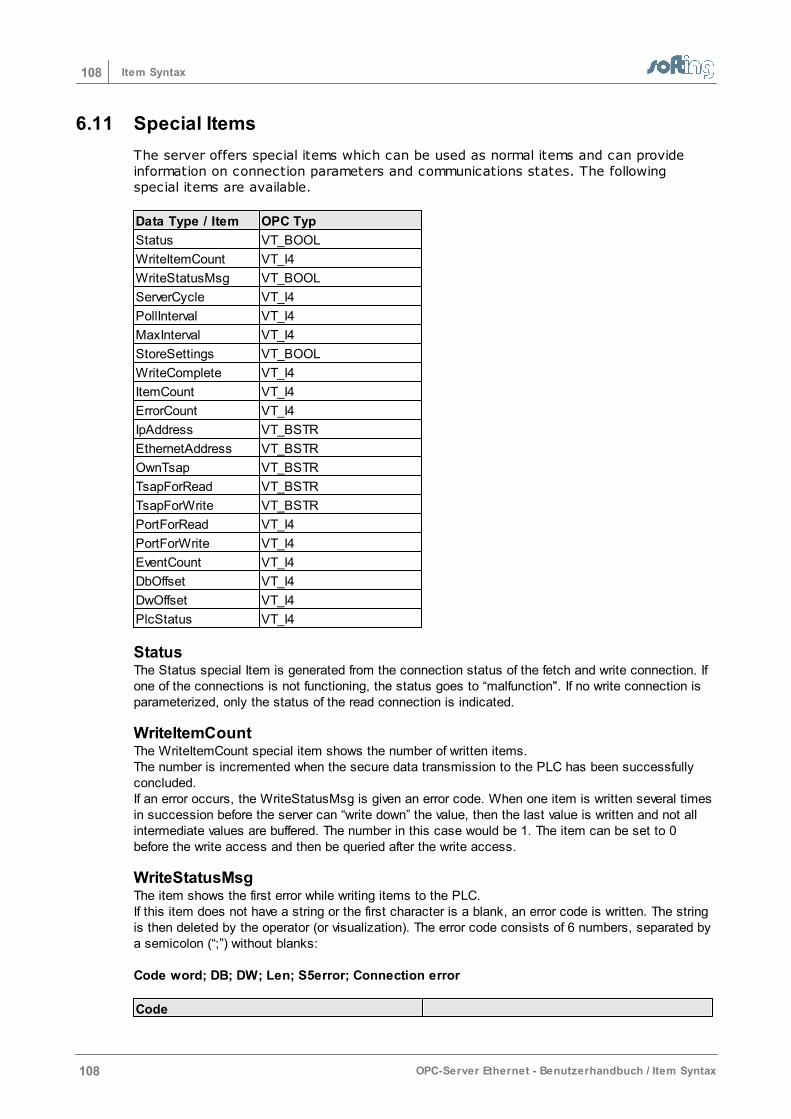
108 Item Syntax
108 OPC-Server Ethernet - Benutzerhandbuch / Item Syntax
6.11 Special Items
The server offers special items which can be used as normal items and can provideinformation on connection parameters and communications states. The followingspecial items are available.
Data Type / Item OPC Typ
Status VT_BOOL
WriteItemCount VT_I4
WriteStatusMsg VT_BOOL
ServerCycle VT_I4
PollInterval VT_I4
MaxInterval VT_I4
StoreSettings VT_BOOL
WriteComplete VT_I4
ItemCount VT_I4
ErrorCount VT_I4
IpAddress VT_BSTR
EthernetAddress VT_BSTR
OwnTsap VT_BSTR
TsapForRead VT_BSTR
TsapForWrite VT_BSTR
PortForRead VT_I4
PortForWrite VT_I4
EventCount VT_I4
DbOffset VT_I4
DwOffset VT_I4
PlcStatus VT_I4
StatusThe Status special Item is generated from the connection status of the fetch and write connection. Ifone of the connections is not functioning, the status goes to “malfunction". If no write connection isparameterized, only the status of the read connection is indicated.
WriteItemCountThe WriteItemCount special item shows the number of written items. The number is incremented when the secure data transmission to the PLC has been successfullyconcluded. If an error occurs, the WriteStatusMsg is given an error code. When one item is written several timesin succession before the server can “write down” the value, then the last value is written and not allintermediate values are buffered. The number in this case would be 1. The item can be set to 0before the write access and then be queried after the write access.
WriteStatusMsgThe item shows the first error while writing items to the PLC. If this item does not have a string or the first character is a blank, an error code is written. The stringis then deleted by the operator (or visualization). The error code consists of 6 numbers, separated bya semicolon (“;”) without blanks: Code word; DB; DW; Len; S5error; Connection error
Code
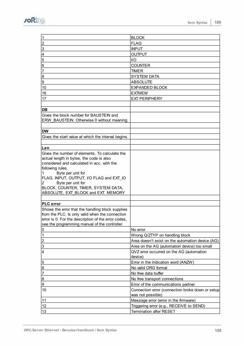
109Item Syntax
OPC-Server Ethernet - Benutzerhandbuch / Item Syntax 109
1 BLOCK
2 FLAG
3 INPUT
4 OUTPUT
5 I/O
6 COUNTER
7 TIMER
8 SYSTEM DATA
9 ABSOLUTE
10 EXPANDED BLOCK
16 EXTMEM
17 EXT PERIPHERY
DB
Gives the block number for BAUSTEIN andERW_BAUSTEIN. Otherwise 0 without meaning.
DW
Gives the start value at which the interval begins.
Len
Gives the number of elements. To calculate theactual length in bytes, the code is alsoconsidered and calculated in acc. with thefollowing rules.1 Byte per unit for FLAG, INPUT, OUTPUT, I/O FLAG and EXT_IO2 Byte per unit for BLOCK, COUNTER, TIMER, SYSTEM DATA,ABSOLUTE, EXT_BLOCK and EXT. MEMORY
PLC error
Shows the error that the handling block suppliesfrom the PLC. Is only valid when the connectionerror is 0. For the description of the error codes,see the programming manual of the controller.
0 No error
1 Wrong Q/ZTYP on handling block
2 Area doesn’t exist on the automation device (AG)
3 Area on the AG (automation device) too small
4 QVZ error occurred on the AG (automationdevice)
5 Error in the indication word (ANZW)
6 No valid ORG format
7 No free data buffer
8 No free transport connections
9 Error of the communications partner
10 Connection error (connection broke down or setupwas not possible)
11 Message error (error in the firmware)
12 Triggering error (e.g., RECEIVE to SEND)
13 Termination after RESET
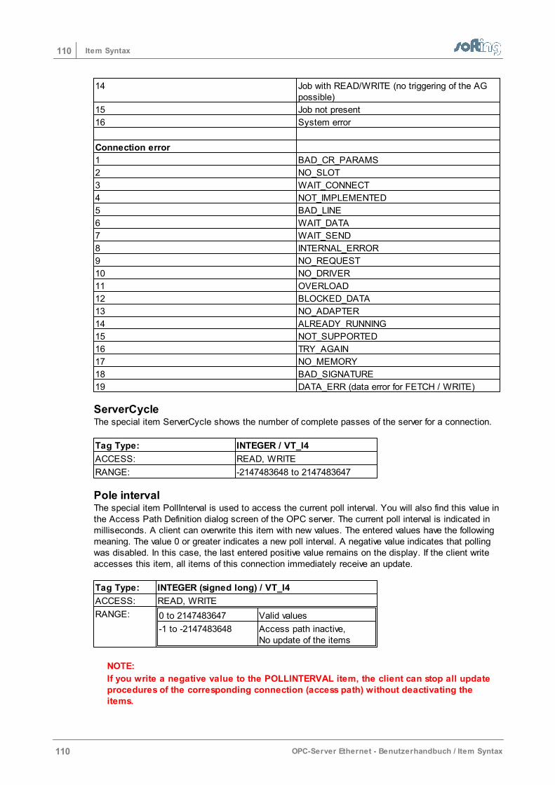
110 Item Syntax
110 OPC-Server Ethernet - Benutzerhandbuch / Item Syntax
14 Job with READ/WRITE (no triggering of the AGpossible)
15 Job not present
16 System error
Connection error
1 BAD_CR_PARAMS
2 NO_SLOT
3 WAIT_CONNECT
4 NOT_IMPLEMENTED
5 BAD_LINE
6 WAIT_DATA
7 WAIT_SEND
8 INTERNAL_ERROR
9 NO_REQUEST
10 NO_DRIVER
11 OVERLOAD
12 BLOCKED_DATA
13 NO_ADAPTER
14 ALREADY_RUNNING
15 NOT_SUPPORTED
16 TRY_AGAIN
17 NO_MEMORY
18 BAD_SIGNATURE
19 DATA_ERR (data error for FETCH / WRITE)
ServerCycleThe special item ServerCycle shows the number of complete passes of the server for a connection.
Tag Type: INTEGER / VT_I4
ACCESS: READ, WRITE
RANGE: -2147483648 to 2147483647
Pole intervalThe special item PollInterval is used to access the current poll interval. You will also find this value inthe Access Path Definition dialog screen of the OPC server. The current poll interval is indicated inmilliseconds. A client can overwrite this item with new values. The entered values have the followingmeaning. The value 0 or greater indicates a new poll interval. A negative value indicates that pollingwas disabled. In this case, the last entered positive value remains on the display. If the client writeaccesses this item, all items of this connection immediately receive an update.
Tag Type: INTEGER (signed long) / VT_I4
ACCESS: READ, WRITE
RANGE: 0 to 2147483647 Valid values
-1 to -2147483648 Access path inactive,No update of the items
NOTE:
If you write a negative value to the POLLINTERVAL item, the client can stop all updateprocedures of the corresponding connection (access path) without deactivating theitems.
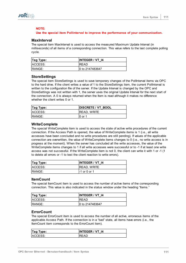
111Item Syntax
OPC-Server Ethernet - Benutzerhandbuch / Item Syntax 111
NOTE:
Use the special item Pollinterval to improve the performance of your communication.
MaxIntervalThe special item MaxInterval is used to access the measured Maximum Update Interval (inmilliseconds) of all items of a corresponding connection. This value refers to the last complete pollingcycle.
Tag Type: INTEGER / VT_I4
ACCESS: READ
RANGE: 0 to 2147483647
StoreSettingsThe special item StoreSettings is used to save temporary changes of the PollInterval items via OPCto the hard drive. If the client writes a value of 1 to the StoreSettings item, the current PollInterval iswritten to the configuration file of the server. If the Update Interval is changed by the OPC andStoreSettings was not written with 1, the server uses the original Update Interval for the next start ofthe connection. A 0 is always returned when the Item is read although it makes no differencewhether the client writes 0 or 1.
Tag Type: DISCRETE / VT_BOOL
ACCESS: READ, WRITE
RANGE: 0 or 1
WriteCompleteThe special WriteComplete item is used to access the state of active write procedures of the currentconnection. If the Access Path is opened, the value of WriteComplete items is 1 (i.e., all writeaccesses have been concluded and no write procedures are still pending). If values of the applicableconnection are overwritten, the value of WriteComplete items changes to 0 (i.e., no write access is inprogress at the moment). When the server has concluded all the write accesses, the value of theWriteComplete items changes to 1 if all write accesses were successful or to -1 if at least one writeaccess was not successful. If the WriteComplete item is not 0, the client can write it with 1 or -1 (1to delete all errors or -1 to test the client reaction to write errors).
Tag Type: INTEGER / VT_I4
ACCESS: READ, WRITE
RANGE: -1 or 0 or 1
ItemCountThe special ItemCount item is used to access the number of active items of the correspondingconnection. This value is also indicated in the status window under the heading “Items.”
Tag Type: INTEGER / VT_I4
ACCESS: READ
RANGE: 0 to 2147483647
ErrorCountThe special ErrorCount item is used to access the number of all active, erroneous items of theapplicable Access Path. If the connection is in a “bad” state, all items have errors (i.e., theItemCount item corresponds to the ErrorCount item).
Tag Type: INTEGER / VT_I4
ACCESS: READ
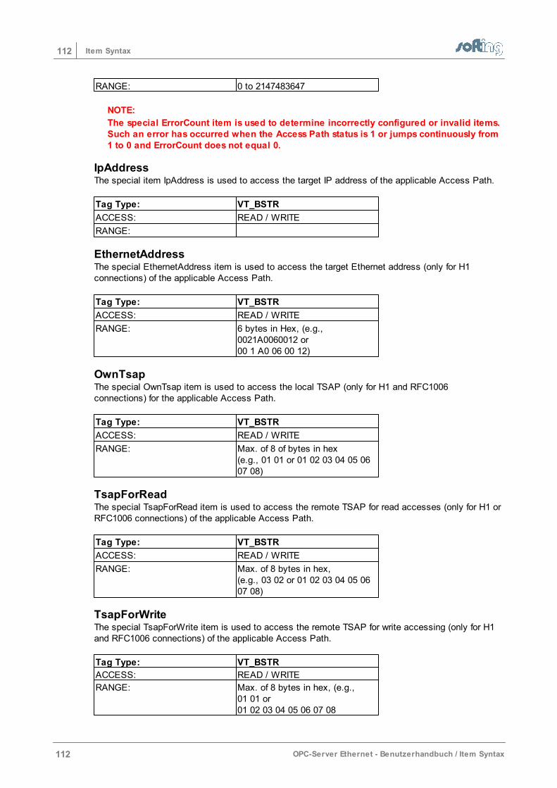
112 Item Syntax
112 OPC-Server Ethernet - Benutzerhandbuch / Item Syntax
RANGE: 0 to 2147483647
NOTE:
The special ErrorCount item is used to determine incorrectly configured or invalid items.Such an error has occurred when the Access Path status is 1 or jumps continuously from1 to 0 and ErrorCount does not equal 0.
IpAddressThe special item IpAddress is used to access the target IP address of the applicable Access Path.
Tag Type: VT_BSTR
ACCESS: READ / WRITE
RANGE:
EthernetAddressThe special EthernetAddress item is used to access the target Ethernet address (only for H1connections) of the applicable Access Path.
Tag Type: VT_BSTR
ACCESS: READ / WRITE
RANGE: 6 bytes in Hex, (e.g.,0021A0060012 or 00 1 A0 06 00 12)
OwnTsapThe special OwnTsap item is used to access the local TSAP (only for H1 and RFC1006connections) for the applicable Access Path.
Tag Type: VT_BSTR
ACCESS: READ / WRITE
RANGE: Max. of 8 of bytes in hex (e.g., 01 01 or 01 02 03 04 05 0607 08)
TsapForReadThe special TsapForRead item is used to access the remote TSAP for read accesses (only for H1 orRFC1006 connections) of the applicable Access Path.
Tag Type: VT_BSTR
ACCESS: READ / WRITE
RANGE: Max. of 8 bytes in hex, (e.g., 03 02 or 01 02 03 04 05 0607 08)
TsapForWriteThe special TsapForWrite item is used to access the remote TSAP for write accessing (only for H1and RFC1006 connections) of the applicable Access Path.
Tag Type: VT_BSTR
ACCESS: READ / WRITE
RANGE: Max. of 8 bytes in hex, (e.g., 01 01 or 01 02 03 04 05 06 07 08
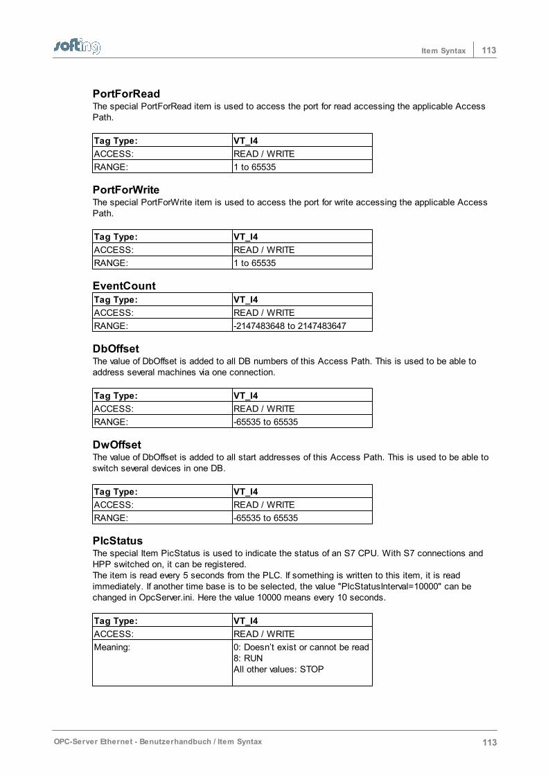
113Item Syntax
OPC-Server Ethernet - Benutzerhandbuch / Item Syntax 113
PortForReadThe special PortForRead item is used to access the port for read accessing the applicable AccessPath.
Tag Type: VT_I4
ACCESS: READ / WRITE
RANGE: 1 to 65535
PortForWriteThe special PortForWrite item is used to access the port for write accessing the applicable AccessPath.
Tag Type: VT_I4
ACCESS: READ / WRITE
RANGE: 1 to 65535
EventCountTag Type: VT_I4
ACCESS: READ / WRITE
RANGE: -2147483648 to 2147483647
DbOffsetThe value of DbOffset is added to all DB numbers of this Access Path. This is used to be able toaddress several machines via one connection.
Tag Type: VT_I4
ACCESS: READ / WRITE
RANGE: -65535 to 65535
DwOffsetThe value of DbOffset is added to all start addresses of this Access Path. This is used to be able toswitch several devices in one DB.
Tag Type: VT_I4
ACCESS: READ / WRITE
RANGE: -65535 to 65535
PlcStatusThe special Item PicStatus is used to indicate the status of an S7 CPU. With S7 connections andHPP switched on, it can be registered. The item is read every 5 seconds from the PLC. If something is written to this item, it is readimmediately. If another time base is to be selected, the value "PlcStatusInterval=10000" can bechanged in OpcServer.ini. Here the value 10000 means every 10 seconds.
Tag Type: VT_I4
ACCESS: READ / WRITE
Meaning: 0: Doesn’t exist or cannot be read8: RUNAll other values: STOP

114 OPC-Server Ethernet - Benutzerhandbuch / Index
114 Index
Index- A -AB ControlLogiX Symbol Import 63
AB ControlLogiX Symbols 63
About 68
Access Path 39, 40, 41, 51, 52, 53, 54, 66, 71
Access Path List 36
Access via OPCpipe 41
Accessories 77, 79, 80, 81
Allen Bradley 25, 49, 63, 79, 95
AppCount 55
AppTimeout 55
Arrays 103
Auto Logoff Timeout 55
- C -Close Server 80
CLX 25, 40, 41, 49, 63, 79
CLX Protocol Settings 49
Configuration 33, 39, 54, 66
Configuration File Directory 55
ConnCount 55
Connection 39, 40, 41, 51, 52, 53, 54, 66
ConnTimeout 55
ControlLogiX 25, 49, 63, 79
Copy Access Path 52
Copy connection 52
- D -Data Types 55, 107
DCOM 14
DCOM Configuration – General 15
DCOM Configuration: Client Computer 19
DCOM Configuration: Client Computer MSDTC 19
DCOM Configuration: Client Computer Options 19
DCOM Configuration: Client Computer StandardCharacteristics 19
DCOM Configuration: Client Computer StandardProtocols 19
DCOM Configuration: Server Computer 16
DCOM Workplace Settings 16
Delete 53
Delete Access Path 53
Delete connection 53
Dialog Screens 66
Dialogs 39, 54
Directory for Configuration File 65
- E -Edit Connection 51
Entering the Password 68
Events from the PLC 48
- F -Folder for configuration file 55
- H -H1 60
Help Overview 7
How To Proceed 30
- I -IBHLink 25
INAT OPC-Server - General 9
IP address 41, 44, 66
Item Syntax 83, 84, 88, 92, 95, 97, 100
- L -License 67
License conditions 67
License entry 67
License Overview 67
License Requirements 10
Licensing 31
Lizenz 80
Logger 9, 37, 58, 59, 77, 80
Logger Memory Settings 59
Logger Settings 58
- M -MAC 60
MAC address 60, 66
Master-Slave 77
MELSEC-Q 26, 40, 41, 50, 79, 97
MELSEC-Q Item Syntax 97
Melsec-Q Protocol Settings 50
Menu 71, 72, 73, 74
Menu Connection 71
OPC-Server Ethernet - Benutzerhandbuch / Index 115
115Index
Menu Diagnostics 72
Menu File 71
Menu Help 74
Menu Settings 73
Menu Station 72
Menu Symbols 73
Mitsubishi 26, 50, 79, 97
Modbus 24, 40, 41, 48, 63, 79, 92
Modbus General Information 24
Modbus Item Syntax 92
Modbus Protocol Settings 48
Modbus Symbol Import 63
- N -NetCon Configuration 38
NetCon OPC 77
netLINK 25, 40, 41, 79
Network Parameters 51
Network Protocol 40
Network Settings 66
Network TCP/IP parameters 51
New Access Path 39
New Connection 39, 40
New Connection (Access Path) 39
New Station 69
- O -on/off 53
Online Diagnosis 33
OPC Basics 20, 21
OPC Client 81
OPC DA Spezifikation 21
OPC Data Access 21
OPC Server Connection 41
OPC Server Settings 16, 17, 18
OPC Server Settings End points 18
OPC Server Settings Execution Location 17
OPC Server Settings General 17
OPC Server Settings Identity 18
OPCpipe 27, 39, 40, 41, 79, 102
OPCpipe – General Information 27
OPCpipe Client 39, 102
OPCpipe Item Syntax 102
OPCpipe Parameters 52
OPCpipe Server 39, 102
OPCpipe Settings 52
Operation and configuration 29
Operator Control and Configuration 29
Optimizations for Write 55
Order number 79
Overview 9
- P -Password 60, 68, 77
PLC Connection 41
PLC Connections 23
PLC-5 25, 40, 41, 79, 95
PLC-5 / SLC Item Syntax 95
Port 41, 45
Port number 45
Program start 77
Protocol 40
Protocol Settings 48, 49, 50
- R -Rockwell 25, 49, 63, 79, 95
Routing 41, 47
Routing TSAPs 47
- S -S5 24, 40, 41, 79, 88
S5 – General Information 24
S5 Item Syntax 88
S5-String 55
S7 23, 40, 41, 46, 62, 79, 84
S7 General Information 23
S7 Item Syntax 84
S7 Symbol Import 62
S7-String 55
Screens 33, 39, 54, 66
Security OPC Server Settings 17
Selecting the Stations 68
Send/Receive 26, 40, 41, 48, 79, 100
Send/Receive – General Information 26
Send/Receive Item Syntax 100
Server Revision 12
Server settings 51
Server Symbol Edit 61
Server System Settings 55
Server Tray 80
Server Type 79
Simulation 41, 51
SLC 25, 40, 41, 79, 95
Special Items 108
Standard Properties 16
Standard Protocols 16
116 OPC-Server Ethernet - Benutzerhandbuch / Index
116 Index
Standard Security DCOM Configuration: ClientComputer 19
Start program 77
Start Server 80
Station not found 70
Station Parameters 66
Station Password 60, 68
Stert NetCon OPC 80
Suffixe 104
Switching a Connection Inactive 53
Symbols 61, 62, 63
Syntax of IP Adresses 44
System Prerequisites 10
- T -The Basics 14
Timeouts 55
Tool Bar 32
Troubleshooting 75
TSAP 41, 45, 46, 47
TSAP for S7 connections 46
- V -Versions 67
- W -What Is DCOM? 14
What Is OPC? OPC Basics 20
Workplace Settings 16
Workplace Settings General 16
Workplace Settings MSDTC 16
Workplace Settings Options 16
Workplace Settings Standard Properties 16
Workplace Settings Standard Protocols 16
Workplace Settings Standard Security 16
Write via OPCpipe 41