opel astra h manual
DESCRIPTION
Secondhand Astra come with no manual? Look no further!TRANSCRIPT
VAUXHALL Astra
Owner’s Manual
0
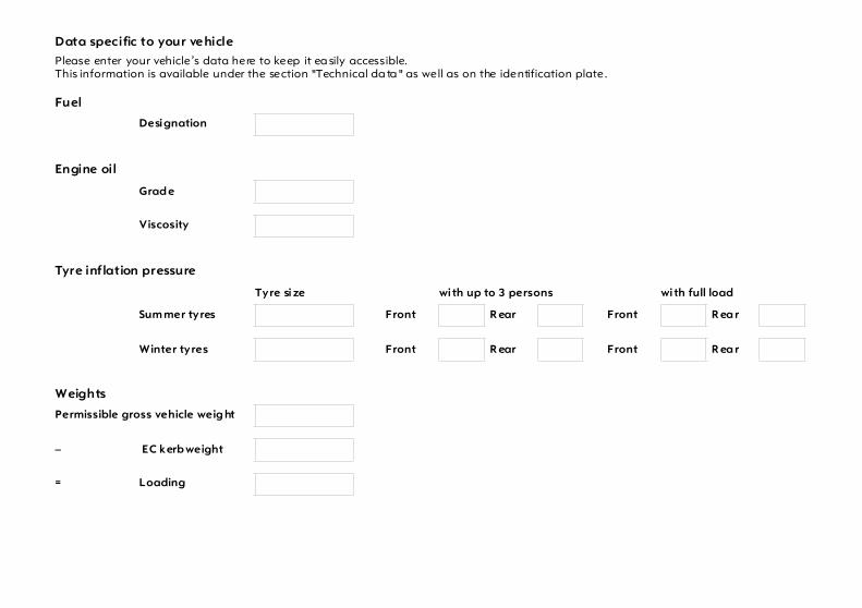
Data specific to your vehiclePlease enter your vehicle’s data here to keep it ea sily accessible.This information is available under the section "Technical da ta " as well as on the identification plate.
Fuel
Designation
Engine oil
Grad e
Viscosity
Tyre inflation pressure
Tyre size with up to 3 persons with full load
Sum mer tyres Front R ear Front R ea r
Winter tyres Front R ear Front R ea r
Weights
Permissible gross vehicle weig ht
– EC kerb weight
= Loading

1
Your AstraDeveloped to the la test findings of vehic le research, it offers technical sophistication and exceptiona l comfort.
Your vehicle represents an ideal synthesis of ad vanced technolog y, outsta nding safety, environm ental compatibility and economy in opera tion.
It now lies with you to drive your vehicle safely and to see it performs perfectly.
This Owner's Manual provides you with all the necessary information to tha t end.
The Owner's Manual should a lways be kept in the vehicle: ready to hand in the g love com partment.
Make use of the Owner's Manual: z Its “In brief” section will give you an initial overview. z Its index will help you find what you want. z It will familiarize you with the sophisticated technology. z It will increase your pleasure in your vehicle. z It will help you to handle your vehicle expertly.
The Owner's Manual is designed to be clearly laid-out and easily understood.
This symb ol:6 signifies: continue reading on next page.
3 The asterisk sig nifies equipment op tions not in all vehicles (model variants, engine options, models specific to one country, op tional equipment, Genuine Vauxhall Parts and Accessories).
Yellow arrows in the illustrations serve as points of reference or ind icate some action to be performed.
Black arrow s in the illustrations indicate a reaction or a second ac tion to be perform ed.
We w ish you m any hours of pleasurable drivingYour Va uxhall team
Text highlighted in yellow in p artic ular indica tes possible risk of accident and injury. Disregard of these notes can lead to injuries which may b e fatal. Vehicle passengers must b e informed accordingly.

2

Contents
3
Comm itment to custom er satisfaction:Our aim: to keep you happy with your vehicle. All Vauxhall Authorised Repairers offer first class service at competitive prices. Experienced, factory-trained technicians w ork according to factory instructions.Your Authorised Repairer can supply you with GENUINE VAU XHALL-APPROVED PARTS, which have und ergone stringent quality and precision chec ks, and of course useful and attrac tive VAUXHALL APPROVED ACCESSORIES.Our nam e i s your guara ntee!
For d eta ils of theVa uxhall Authorised Rep airer Netw orkplease r ing this number; 01582 - 427200
In Brief . ..... .... ..... .... .... ..... .... ..... .... ..... .... .... . 4Instrum ents ... ..... .... .... ..... .... ..... .... ..... .... .. 26Keys, Doors,
Bonnet ... .... ..... .... .... ..... .... ..... .... ..... .... .. 54Seats, Interior ..... .... .... ..... .... ..... .... ..... .... .. 67Safety system s ... .... .... ..... .... ..... .... ..... .... .. 87Lighting ..... .... ..... .... .... ..... .... ..... .... ..... .... 108Windows, Sun Roof .. ..... .... ..... .... ..... .... 115Clim ate c ontrol . .... .... ..... .... ..... .... ..... .... 120Easytronic .... ..... .... .... ..... .... ..... .... ..... .... 136Automatic transm ission .... ..... .... ..... .... 144Driving hints . ..... .... .... ..... .... ..... .... ..... .... 150Saving fuel,
Protecting the environment ... ..... .... 152Fuel consum ption,
fuel, refuelling ... .... ..... .... ..... .... ..... .... 154Catalytic converter, exhaust gases .... 157Drive Control Systems ... .... ..... .... ..... .... 162Brakes ... ..... .... ..... .... .... ..... .... ..... .... ..... .... 176Wheels, tyres . ..... .... .... ..... .... ..... .... ..... .... 180Roof racks,
Carava n and trailer towing ... ..... .... 186Self-help .... .... ..... .... .... ..... .... ..... .... ..... .... 195If you ha ve a problem ... .... ..... .... ..... .... 230Service plan, m aintenance ..... .... ..... .... 232Vehicle care .. ..... .... .... ..... .... ..... .... ..... .... 244Technical Data . .... .... ..... .... ..... .... ..... .... 248Index . .... ..... .... ..... .... .... ..... .... ..... .... ..... .... 278
4
In Brief
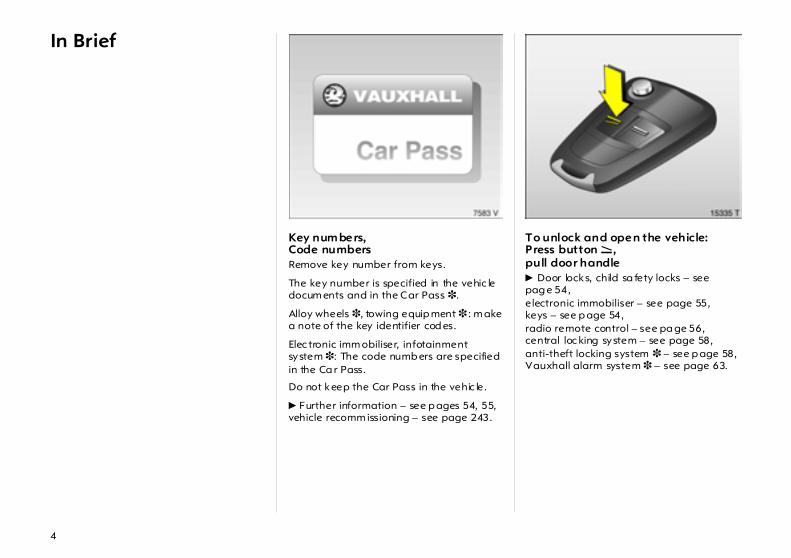
Key num bers,Code numbers Remove key number from keys.
The key number is specified in the vehic le docum ents and in the Car Pass 3.
Alloy wheels 3, towing equip ment 3 : m ake a note of the key identifier cod es.
Elec tronic imm obiliser, infotainment system 3: The code numb ers are specified in the Ca r Pass.
Do not keep the Car Pass in the vehic le.
6 Further information – see p ages 54, 55,vehicle recomm issioning – see page 243.
To unlock and open the vehicle: Press button q ,pull door handle 6 Door locks, child sa fety locks – see pag e 54,electronic immobiliser – see page 55,keys – see p age 54,radio remote control – see pa ge 56,central loc king system – see page 58,anti-theft locking system 3 – see p age 58,Vauxhall alarm system 3 – see page 63.
5
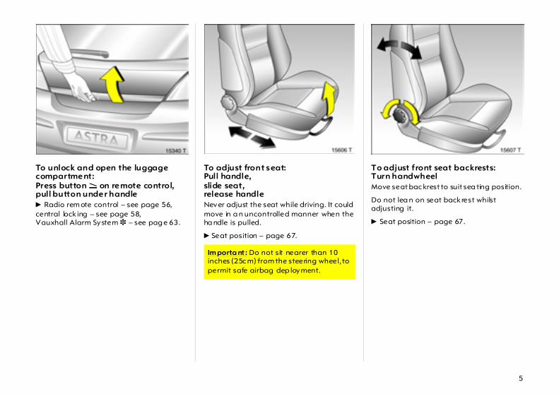
To unlock and open the luggage compartment: Press button q on remote control,pull button under handle 6 Radio rem ote control – see page 56,central lock ing – see page 58,Vauxhall Alarm System 3 – see pag e 63.
To adjust front seat:Pull handle,slide seat,release handle Never adjust the seat while driving. It could move in a n uncontrolled manner when the ha ndle is pulled.
6 Seat position – page 67.
To adjust front seat backrests:Turn handwheel Move seat bac krest to suit sea ting position.
Do not lea n on seat back rest whilst adjusting it.
6 Seat position – page 67.
Im porta nt : Do not sit nearer than 10 inches (25c m) from the steering wheel, to permit safe airbag dep loyment.

6
To adjust front seat lumbar support 3 :Turn handwheel Adjust lumb ar support to suit personal req uirements.
Do not lean on sea t backrest whilst adjusting it.
6 Seat position – p age 67.
To adjust front seat height 3:Operate lever on outboard side of seat Pump direction of the lever Up: Raises seatDow n: Lowers seat
6 Seat position – page 67.
To adjust front seat inclination 3 :Pull inner lever on front of seat,adjust inclination,release lever,engage seat in position Adjust the inclination b y distributing b od y weight.
6 Seat position – page 67.
7
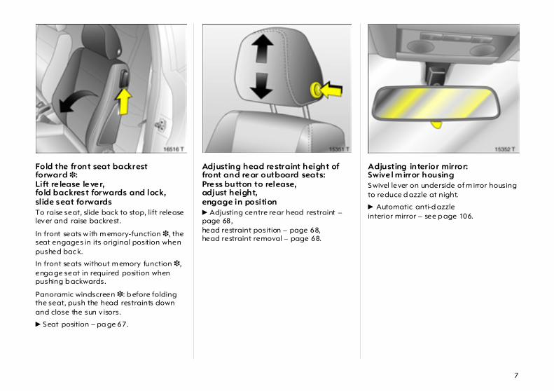
Fold the front seat backrest forward 3:Lift re lease lever,fold backrest forwards and lock,slide seat forwardsTo raise seat, slide back to stop, lift release lever and raise backrest.
In front seats w ith m emory-function 3, the seat engages in its original position when pushed bac k.
In front seats without m emory function 3, enga ge seat in required position when pushing b ackwards.
Panoramic windscreen 3: b efore folding the seat, push the head restraints down and close the sun v isors.
6 Seat position – pa ge 67.
Adjusting head restraint height of front and rear outboard seats:Press button to release,adjust height,engage in position 6 Adjusting centre rear head restraint – page 68,head restraint position – page 68,head restraint removal – page 68.
Adjusting interior mirror:Swivel m irror housingSwivel lever on underside of m irror housing to reduce d azzle at night.
6 Automatic anti-d azzleinterior mirror – see p age 106.
8
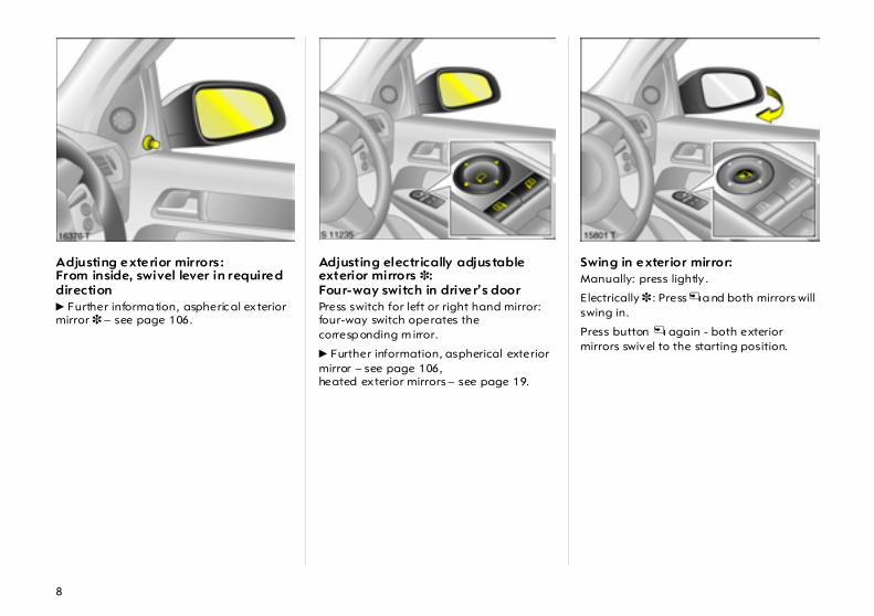
Adjusting exterior mirrors :From inside, swivel lever in required direction 6 Further informa tion, aspheric al exterior mirror 3 – see page 106.
Adjusting electrically adjustable exterior mirrors 3:Four-way switch in driver’s door Press switch for left or right hand mirror: four-way switch operates the corresp onding m irror.
6 Further information, aspherical exterior mirror – see page 106,heated exterior mirrors – see page 19.
Swing in exterior mirror: Manually: press lightly .
E lectrically 3 : Press n a nd both mirrors will swing in.
Press button n again - both exterior mirrors swivel to the starting position.

9
Fitting seat belt:Draw seat belt smoothly from inertia reel,guide over shoulderand engage in buckle The b elt must not be twisted at any point. The lap belt must lie snugly against the body. The backrest must not be tilted bac k too far (recomm ended tilting angle approx. 25 ° ).
To release belt, press red button on belt buckle.
6 Seat belt – see page 88,airbag systems – see page 92,seat p osition – see page 67.
Disengaging steering column lock:To re lease the lock,move the steering wheel slightly,turn key to pos ition 1 Locking stages:0 = ignition off1 = steering free, ignition off2 = ignition on,
for d iesel engine: p reheating3 = start
6 Starting – see page 22,electronic im mobiliser – see pag e 55,remove key and loc k steering w heel – see page 23.
Steering wheel adjustment:Move lever down,adjust height and distance,move lever up,engage Adjust steering wheel only when vehicle is stationary and steering colum n loc k is released.
6 Airb ag systems – see p age 92.

10

11
Page1 Side air vents ... ..... .... ..... .... .... ..... .... 123
2 Front pa ssenger airbag .... .... ..... .... . 93
3 Centre air vents .... .... ..... .... .... ..... ... 123
4 Central information display fortime, date, outside temperature,infotainment system 3 ,check control 3 .... .... ..... .... .... ..... .... ..50Trip computer 3 ... .... ..... .... .... ..... 40, 46Clim ate control system 3 . .... ..... ... 127
5 Heated seat (left) 3 . ..... .... .... ..... ... 123Deflation detection system 3 .. ..... .... .... ..... .... 171Tyre pressuremonitoring system 3 ..... .... .... ..... .... 172Parking distance sensor3 . .... ..... ... 168Haza rd warning lights .. .... .... ..... .... ..16Central locking system . .... .... ..... .... ..59SPORT mode 3 ..... .... ..... .... .... ..... .... 164Heated seat (right) 3 .... .... .... ..... ... 123
6 Turn signal lights, hea dlight fla sh,Dipped beam, main bea m ... ..... .... ..15Door-to-door light function 3 ... .... 112Parking lights ... ..... .... ..... .... .... ..... ... 112Cruise control 3 .... .... ..... .... .... .. 14, 166
7 Remote control 3 forinfotainment system ..... .... .... ..... .... ..52
Pa ge8 Instruments . ..... .... ..... .... .... ..... .... ..... .. 26
9 Horn ... ..... .... ..... .... ..... .... .... ..... .... ..... .. 17
10 Windscreen wiper,wind screen wash system,headlight wash system 3 andrear window w ash system .... .... .17, 18
11 Pa rk ing lights, dipped beam ... ..... 108Instrument illumination ... ..... .... ..... 112Fog tail lig ht .... .... ..... .... .... ..... .... ..... 109Fog lights 3 ..... .... ..... .... .... ..... .... ..... 109Head lig ht range adjustment 3 .... 110
12 Bonnet release lever . .... .... ..... .... ..... . 66
Page13 Sta rter switch
with steering wheel lock .. .... ..... .... .... . 9
14 Accelerator pedal .... .... ..... .... . 150, 151
15 Brake pedal .... .... ..... .... .. 151, 176, 177
16 Clutch pedal 3 .... ..... .... ..... .... ..... .... 151
17 Steering w heel a djustment . ..... .... .... . 9
18 Ashtray 3 ... .... .... ..... .... ..... .... ..... .... ... 84Cigarette lighter 3 .. .... ..... .... ..... .... .. 83
19 Clim ate c ontrol .. ..... .... ..... .... ..... .... 120
20 Infotainment system 3 ..... .... ..... .... .. 53
21 Glove compartment ... ..... .... ... 85, 133
12
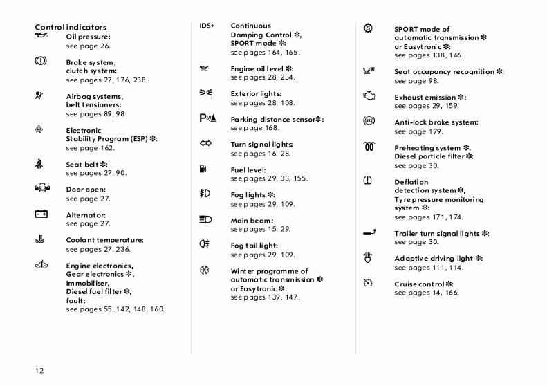
Control indicators I Oil pressure:
see page 26.
R Brake system ,clutc h system: see pages 27, 176, 238.
v Airb ag systems,belt tensioners: see pages 89, 98.
v Elec tronicStability Progra m (ESP) 3: see page 162.
X Seat bel t 3: see pages 27, 90.
Q Door open: see page 27.
p Alternator: see page 27.
W Coola nt temperature: see pages 27, 236.
A Eng ine electr onics,Gear electronics 3 ,Im mobil iser, Diesel fuel fil ter 3,fault : see pages 55, 142, 148, 160.
IDS+ Continuous Damping Control 3,SPORT m ode 3: see p ages 164, 165.
S Engine oil level 3: see p ages 28, 234.
8 Exterior lights: see p ages 28, 108.
r Pa rking distance sensor3 : see p age 168.
O Turn sig nal lig hts: see p ages 16, 28.
Y Fuel level: see p ages 29, 33, 155.
> Fog l ights 3: see p ages 29, 109.
C Main beam : see p ages 15, 29.
r Fog tail light: see p ages 29, 109.
T Winter program me of automa tic tra nsm ission 3or Easytronic 3 : see p ages 139, 147.
1 SPORT mode of automatic transmission 3or Easyt ronic 3: see pages 138, 146.
y Seat occupancy recognition 3: see page 98.
Z Exhaust emission 3 : see pages 29, 159.
u Anti -lock b rake system: see page 179.
! Prehea ting system 3,Diesel particle filter 3: see page 30.
w Deflation detection system 3,Tyre p ressure monitoring system 3: see pages 171, 174.
g Trai ler turn signal lights 3: see page 30.
B Ad aptive driving light 3: see pages 111, 114.
m Cruise control 3: see pages 14, 166.

13
LightingLight swi tch,stalk positions: see pages 15, 108,
7 Lights off,
8 Parking lights,
9 Dipp ed beam, m ain beam
> Fog lights 3 : see page 109.
r Fog tail light: see page 109.
C Main beam: see page 15.
O Turn signal l ights: see page 16.
k Instrum ent illumina tion: see page 112.
c Courtesy light:see page 113.
a Rea ding lights 3:see p age 113.
¨ Hazard w arning lig hts: see p age 16.
Clim ate control Air distribution: see p ages 121, 131,
L to head a rea v ia adjustab leair vents and to foot well,
M to head a rea v iaadjustable air vents,
l to wind screen,
J to wind screen andto foot well,
K to foot well.
x Air flow: see p ages 121, 131.
Ü Hea ted rear wind ow: see p ages 19, 122.
n Air conditioning system 3: see pages 19, 122.
4 Air rec irculation system 3: see pages 122, 132.
AUTO Autom atic mode 3: see pages 19, 128.
V Demisting and defrosting 3: see pages 19, 125, 126, 130.
ß Heated seats 3 : see page 123.

14
Sun roof 3 ü Sun roof:
opening or tilting – see page 119.
d Sun roof:closing – see page 119.
G Sunbl ind: opening – see page 119.
H Sunbl ind: closing – see page 119.
Windscreen wiper Stalk p osi tions: see pages 17, 18
§ Off,
$ Timed inter val w ipe, orautom atic wipe wi th rain sensor 3,
% Slow
& Fast
Cruise control 3 Buttons on turn signa l stalk:see pages 16, 166.
m Activate, store,accelerate,
g Resumestored speed,decelerate,
§ Dea ctivate.
Date, time, information display,infotainment system
Informat ion displa y: see p age 34.
Ö On button for date and time: see p age 36
; Setting buttons for date and time:see p age 36
Rem ote control forinfotainm ent system 3: see p ages 37, 52.
Miscellaneous p Central loc king system :
loc king – see pag e 58.
q Central loc king system : unlocking – see page 58.
m Central loc king sw itch: see p age 59.
b Va uxhall alarm system 3: see p age 63.
z Child sa fety systemfor rear wind ows 3: see p age 116.
E Deflation detection system 3,Tyre p ressure monitoring system 3: see pages 171, 172.
r Parking dista nce sensor3: see page 168.
SPORT SPORT mode 3 : see page 164.
T Winter prog ramm e,Easytronic 3, Autom atic transmission 3:see pages 139, 147.
j Horn: see page 17.
+ First-aid kit (cushion) 3: see page 200.
¨ Warning triangle 3 : see page 200.

15
Light switch: 7 = Off 8 = Parking lights 9 = Dipped or main beam AUTO = Automatic dipped beam
activation 3 Press > = Fog lights 3
Press r = Fog tail light
6 Further notes – Pag e 108,Autom atic activation of dipped beam 3 – Page 109,Headlight warning device – Page 23,Headlight rang e adjustment 3 – Pa ge 110,Instrument illum ination – Page 112,Door-to-door function – Page 112,Parking light – Pa ge 112,Daytime running lig hts 3 – Page 108.
Dipped and main beam switch:Main beam = Push stalk forwardDipped beam = Push stalk forward
again or pull toward steering wheel
The blue control indicator C is illuminated when main b eam is on.
Headlight flash:Pull stalk towards steering wheel
16
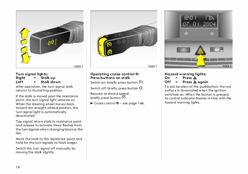
Turn signal lights :Right = Stalk upLeft = Stalk down After operation, the turn signal stalk returns to its starting position.
If the stalk is moved past the resistance point, the turn signal light rema ins on. When the steering wheel moves back toward the straight-ahea d position, the turn signal light is automatically deactivated .
Tap signal: M ove stalk to resistance point and release to activate three flashes from the turn signals when changing lanes or the like.
Move the stalk to the resista nce point and hold for the turn sig nals to flash longer.
Switch the turn signal off manually by moving the sta lk slig htly.
Operating cruise control 3:Press buttons on stalk Switch on: briefly press button m.
Switch off: briefly press button §.
Resume at stored speed: briefly p ress button g.
6 Cruise c ontrol 3 – see page 166.
Hazard w arning lights:On = Press ¨Off = Press ¨ again To aid loc ation of the pushbutton, the red surfac e is illuminated w hen the ignition switched on. When the button is pressed, its control indicator flashes in time with the hazard warning lights.
17
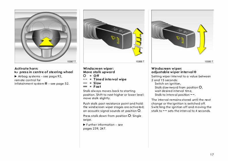
Activate horn: j press in centre of steering wheel 6 Airbag systems – see pag e 92,rem ote control for infotainment system 3 – see page 52.
Windscreen wiper:Move stalk upward § = O ff $ = Timed interval wipe % = Slow & = F ast Stalk alw ays moves back to starting position. Shift to next higher or lower level: move stalk slightly.
Push stalk past resistance point and hold: the wind screen wiper stages are activa ted; an acoustic signal sounds at position §.
Press stalk down from position §: Single swipe.
6 Further information – see pages 239, 247.
Windscreen wiper: adjustable wiper interval 3 Setting wiper interval to a value between 2 and 15 seconds:
Switch on ignition,Stalk d ow nwa rd from position § ,wait desired interval tim e,Stalk to interval position $ .
The interval remains stored until the next change or the ignition is switched off. Switc hing the ignition off and m oving the stalk to $ sets the interval to 4 seconds.

18
Autom atic w iping with rain sensor 3:Move stalk upward $ = automatic wiping with rain
sensor Autom atic wiping $ : The rain sensor detects the a mount of wa ter on the windscreen and automatically regulates the w indscreen wiper.
To switch off, move stalk downwards.
6 Further inform ation – see pages 239, 247.
Operating windscreen andheadlight wash systems 3:Pull stalk towards steering wheel The wiper sw ipes for a few strokes. At low speeds, there is a single post-wash swipe.
The head lig ht wash system 3 ca n be op erated when the lights are on. Wash fluid is sprayed on the headlights. The headlight wash system ca nnot be op erated for 2 minutes thereafter.
On vehicles fitted w ith ra in sensor 3, keep the sensor area c lean.
6 Further information – see pages 239, 247.
Rear window wiper andwash system operation:Wiper on = Push stalk forwardWiper off = Push stalk forward
againWash = Press and hold The rear window w iper swipes in timed interva l mode.
The rear window w iper engages automatically when the wind screen wiper is switched on and reverse gear is eng aged.
6 Further information – see pag es 239, 247.
19
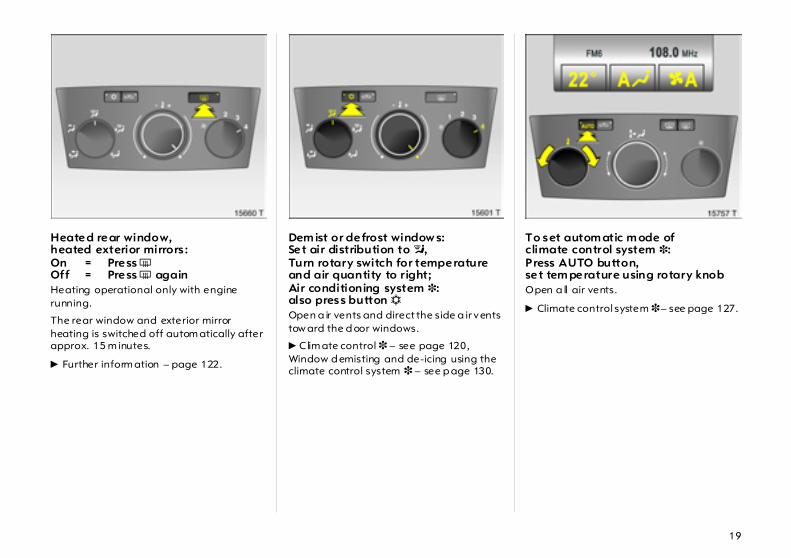
Heated rear window,heated exterior mirrors :On = Press ÜOff = Press Ü againHeating operational only with engine running.
The rear window and exterior mirror heating is switched off autom atically after approx. 15 m inutes.
6 Further inform ation – page 122.
Dem ist or defrost window s: Set air distribution to l,Turn rotary switch for temperatureand air quantity to right; Air conditioning system 3: also press button n Open a ir vents and direct the side a ir vents tow ard the d oor windows.
6 Clim ate control 3 – see page 120,Window d emisting and de-icing using the climate control system 3 – see p age 130.
To set autom atic m ode ofclimate control system 3:Press AUTO button,set tem perature using rotary knob Open a ll air vents.
6 Climate control system 3 – see page 127.
20
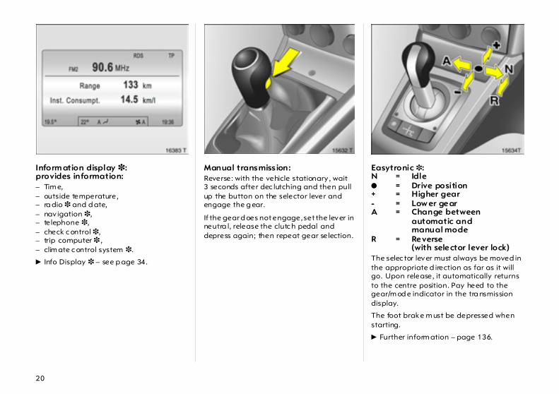
Inform ation display 3:provides information: – Tim e,– outside temperature,– ra dio 3 and d ate,– nav igation 3,– telephone 3,– check c ontrol 3,– trip computer 3 ,– clim ate c ontrol system 3.
6 Info Display 3 – see p age 34.
Manual transmiss ion: Reverse: with the vehicle stationary , wait 3 seconds after dec lutching and then pull up the button on the selector lever and engage the g ear.
If the gear d oes not engage, set the lever in neutra l, release the clutc h pedal and depress again; then repeat gear selection.
Easytronic 3:N = Idle o = Drive position+ = Higher gear- = Low er gearA = Change between
automatic andmanual mode
R = Reverse(with selector lever lock)
The selec tor lever must always be moved in the appropriate d irection as far as it will go. Upon release, it automatically returns to the centre position. Pay heed to the gear/m od e indicator in the tra nsmission display.
The foot brake m ust be depressed when starting.
6 Further inform ation – page 136.
21
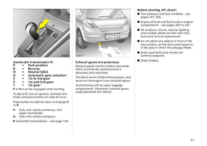
Autom atic transmission 3:P = Park positionR = ReverseN = Neutral (idle)D = Automatic gear selection3 = 1st to 3rd gear2 = 1st and 2nd gear1 = 1st gear P or N m ust be eng aged when starting.
To lea ve P, turn on ignition, activa te foot brake and p ress b utton on selec tor lever.
Press button on selector lever to eng age P or R.
P: Only with vehicle stationary , first apply hand brake
R: Only with vehicle stationary
6 Automatic transmission – see page 144.
Exhaust gases are poisonous Exhaust gases contain carbon monoxide, whic h is extrem ely poisonous b ut is od ourless and colourless.
Therefore never inhale exhaust gases, and never run the engine in an enc losed space.
Avoid driving with an open luggage compartment. Otherw ise, exhaust ga ses could penetrate the interior.
Before starting off, check: z Tyre pressure and tyre condition - see
pages 181, 265.
z Engine oil level a nd fluid levels in engine compartment – see pages 233 to 241.
z All windows, mirrors, exterior lig hting and number plates are free from dirt, snow and ice a nd operational.
z Do not place any objec ts in front of the rear window, on the instrument panel or in the area in which the a irba gs inflate.
z Seats, seat belts and mirrors are correctly a djusted .
z Check brakes.
22
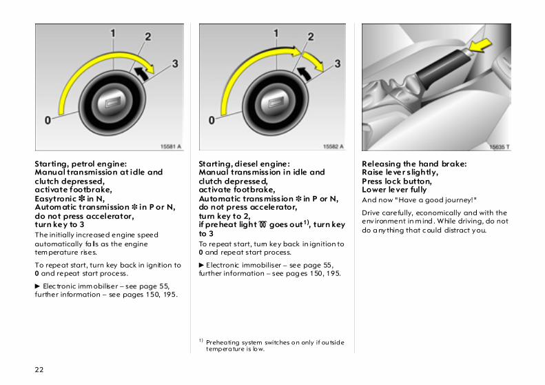
Starting, petrol engine:Manual transmission at idle andclutch depressed,activate footbrake,Easytronic 3 in N,Autom atic transmission 3 in P or N,do not press accelerator,turn key to 3 The initially increased engine speed automatically fa lls as the engine tem perature rises.
To repeat start, turn key back in ignition to 0 and repeat start process.
6 Elec tronic imm obiliser – see page 55,further information – see pages 150, 195.
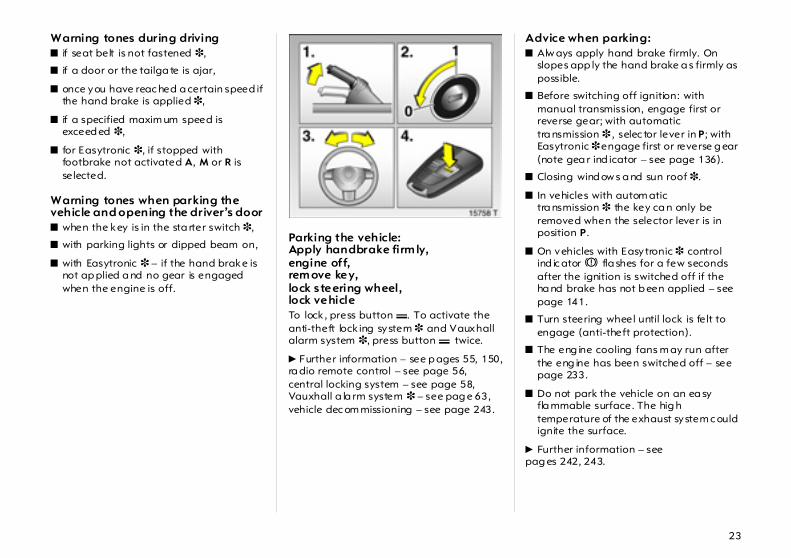
Starting, diesel engine: Manual transmiss ion in idle and clutch depressed,activate footbrake,Automatic transmiss ion 3 in P or N,do not press accelerator,turn key to 2,if preheat light ! goes out1), turn key to 3 To repeat start, turn key back in ignition to 0 and repeat start process.
6 Electronic immobiliser – see page 55,further information – see pag es 150, 195.
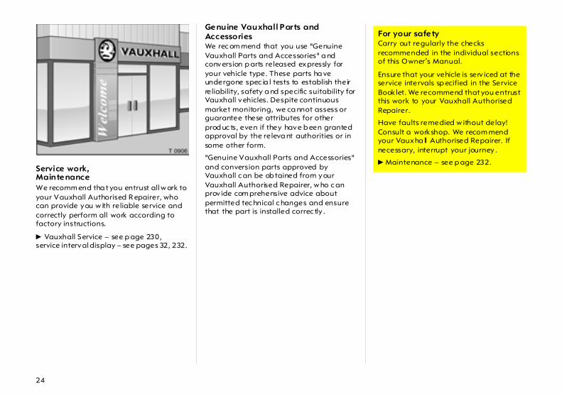
Releasing the hand brake:Raise lever s lightly,Press lock button,Lower lever fully And now "Have a good journey!"
Drive carefully, economically and with the env ironment in m ind . While driving, do not do a nything that c ould distract you.
1) Preheating system switches o n only if ou tside temperature is lo w.
23
Warning tones during driving z if seat belt is not fastened 3,
z if a door or the tailga te is ajar,
z once you have reac hed a certain speed if the hand brake is applied 3,
z if a specified maxim um speed is exceed ed 3,
z for Easytronic 3, if stopped with footbrake not activated A, M or R is selected.
Warning tones when parking the vehicle and opening the driver’s door z when the key is in the sta rter switch 3,
z with parking lights or dipped beam on,
z with Easytronic 3 – if the hand brake is not ap plied a nd no gear is engaged when the engine is off.
Parking the vehicle:Apply handbrake firm ly,engine off,rem ove key,lock steering wheel,lock vehicle To lock , press button p. To activate the anti-theft lock ing system 3 and Vauxhall alarm system 3, press button p twice.
6 Further information – see p ages 55, 150,ra dio remote control – see page 56,central locking system – see page 58,Vauxhall a la rm system 3 – see pag e 63,vehicle dec om missioning – see page 243.
Advice when parking: z Alw ays apply hand brake firmly. On
slopes app ly the hand brake a s firmly as possible.
z Before switching off ignition: with manual transmission, engage first or reverse gear; with automatic tra nsmission 3 , selec tor lever in P; with Easytronic 3 engage first or reverse g ear (note gea r ind icator – see page 136).
z Closing wind ow s a nd sun roof 3.
z In vehicles with autom atic tra nsmission 3 the key ca n only be removed when the selector lever is in position P.
z On vehicles with Easytronic 3 control ind ic ator R fla shes for a few seconds after the ignition is switched off if the ha nd brake has not b een applied – see page 141.
z Turn steering wheel until lock is felt to engage (anti-theft protection).
z The eng ine cooling fans m ay run after the eng ine has been switched off – see page 233.
z Do not park the vehicle on an ea sy fla mmable surface. The hig h temperature of the exhaust system c ould ignite the surface.
6 Further information – see pag es 242, 243.
24
Service work,Maintenance We recomm end tha t you entrust all w ork to your Vauxhall Authorised R epairer, who can provide you w ith reliable service and correctly perform all work according to factory instructions.
6 Vauxhall Service – see p age 230,service interval display – see pages 32, 232.
Genuine Vauxhall Parts and Accessories We rec om mend that you use "Genuine Vauxhall Parts and Accessories" a nd conversion p arts released expressly for your vehicle type. These parts ha ve undergone spec ia l tests to establish their reliability, safety a nd specific suitability for Vauxhall vehicles. Despite continuous market monitoring, we ca nnot assess or guarantee these attributes for other prod uc ts, even if they have b een granted approval by the releva nt authorities or in some other form.
"Genuine Vauxhall Parts and Accessories" and conversion parts approved by Vauxhall c an be ob tained from your Vauxhall Authorised Repairer, w ho c an prov ide com prehensive advice about permitted tec hnical c hanges and ensure that the part is installed correc tly .
For your safety Carry out regularly the checks recommended in the individual sections of this Owner’s Manual.
Ensure that your vehicle is serv iced at the service intervals sp ecified in the Service Book let. We recommend that you entrust this work to your Vauxhall Authorised Repairer.
Have faults remedied w ithout delay! Consult a workshop. We recom mend your Vauxha ll Authorised Repairer. If necessary, interrupt your journey .
6 Maintenance – see p age 232.

25
That was a brief overview of the m ost important information for your first trip in your Astra.
The rem aining chapters of the Owner’s Manual contain important informationon operation, safetyand maintenanceas well as a completeindex.

26
Instruments
Control indicators The control indica tors described here are not p resent in all vehicles. The description applies to all instrum ent versions.
I Oil pressure The control indicator illuminates when the ignition is switched on and goes out shortly after the eng ine starts. Can illuminate intermittently when idling w ith hot engine; must go out when engine speed is increa sed.
27
Illuminates when the engine is runningEngine lubrication ma y b e interrupted. This may result in d amage to the engine a nd /or locking of the drive wheels:
1. Depress clutch.
2. Shift manua l transmission or Easytronic 3 into neutral; for automatic transmission 3, set selector lever to N.
3. Move out of the flow of tra ffic as quickly as possible w ithout impeding other vehicles.
4. Switch off ignition.
Consult a workshop. We recommend your Vauxhall Authorised Repairer.
R Brake system,clutch system The control indica tor illuminates w hen the ignition is switc hed on if the ha nd brake is applied or if the brake or clutc h fluid level is too low. Further information – see pages 176, 238.
For vehicles with Ea sytronic 3 , the c ontrol indica tor flashes for a few seconds when the ig nition is turned off if the handbrake is not a pplied.
v Airbag systems 3,belt tensioners 3 see p ages 89, 98.
v Electronic Stab ility Program 3 see p age 162.
X Seat belt 3 The control indica tor lig hts after the ignition is turned on until the seat b elt is fa stened. When driving begins, the control indica tor flashes. App ly seat b elt – see page 90.
Q Door open Illuminated when a door or the luggage compa rtm ent is open.
p Alterna tor The control indicator illuminates when the ignition is switched on and goes out shortly after the eng ine starts.
Illuminates when the eng ine is runningStop, sw itc h engine off. Ba ttery is not charged. Engine cooling may not be operating. With a diesel engine the brake servo unit ma y stop operating. Consult a workshop. We recommend your Vauxhall Authorised Repa irer.
W Coolant temp era ture Illuminates when the eng ine is runningStop and switch off engine. Coolant temperature too hig h: Danger of engine dam age. Check coolant level imm ediately – see page 236.
6
When the engine is off, considera bly more force is needed to brake and steer.
Do not remove key until vehicle has com e to a sta ndstill, otherwise the steering column lock could engage unexpectedly.
If it illuminates when the hand brake is not applied: S top the vehicle; interrupt your journey im media tely. Consult a workshop . We recommend your Vauxhall Authorised R epairer.
28
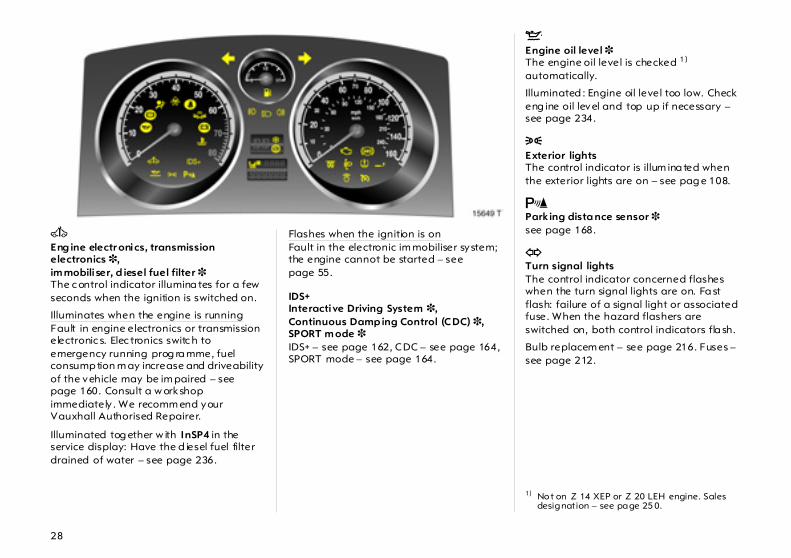
A Eng ine electr onics, transmission electronics 3,im mobili ser, d iesel fuel filter 3 The c ontrol indicator illumina tes for a few seconds when the ignition is switched on.
Illuminates when the engine is running Fault in engine electronics or transmission electronic s. Elec tronics switc h to emergency running prog ra mme, fuel consump tion m ay increase and driveability of the vehicle may be im paired – see page 160. Consult a w orkshop immediately . We recomm end your Vauxhall Authorised Repairer.
Illuminated tog ether w ith InSP4 in the service display: Have the d iesel fuel filter drained of water – see page 236.
Flashes when the ignition is on Fault in the electronic im mobiliser system; the engine cannot be started – see page 55.
IDS+Interactive Driving System 3,Continuous Damp ing Control (CDC) 3, SPORT m ode 3 IDS+ – see page 162, CDC – see page 164, SPORT mode – see page 164.
S Engine oil level 3 The engine oil level is checked 1) automatically.
Illuminated : Engine oil level too low. Check eng ine oil level and top up if necessary – see page 234.
8 Exterior lights The control indicator is illum ina ted when the exterior lights are on – see pag e 108.
r Parking dista nce sensor 3see page 168.
O Turn signal lights The control indicator concerned flashes when the turn signal lights are on. Fa st flash: failure of a signal light or associated fuse. When the hazard flashers are switched on, both control indicators fla sh.
Bulb replacem ent – see page 216. Fuses – see page 212.
1) No t on Z 14 XEP or Z 20 LEH engine. Sales designation – see page 25 0.

29
Y Fuel level Illuminated: Low fuel level. Fuel gauge in reserve a rea.
Flashing: Fuel supply used up, fill tank immediately .
Never let the tank run dry!
Petrol eng ines: erratic fuel supply can cause catalytic converter to overheat – see page 157.
Diesel engines: If the tank is run d ry , bleed the fuel system as described on page 195.
> Fog lights 3 The c ontrol indicator is illum inated when the fog lig hts are on – see page 109.
C Main bea m The c ontrol indicator is illum inated when main beam is on and during headlight flash – see page 15.
r Fog tail light The control indica tor is illuminated when the fog tail light is on – see pag e 109.
T Winter program of automat ic tra nsm ission 3 or Easytronic 3 Control indicator is illuminated when winter prog ra m is enabled.
Further inform ation – see pages 139, 147.
1 SPORT m ode ofautomat ic tra nsm ission 3 or Easytronic 3 The control indica tor is illuminated when SPORT mode is engaged .
Further inform ation – see pages 138, 146.
y Seat occup ancy r ecog ni tion 3 see p age 98.
Z Exhaust emission 3 The control indicator illuminates when the ignition is switched on and goes out shortly after the eng ine starts.
Illuminates when the eng ine is runningFault in emission c ontrol system. The permitted emission limits may be exceeded. Consult a workshop. We recommend your Vauxhall Authorised Repairer.
If it flashes when the engine is runningFault tha t can lea d to destruction of the catalytic converter is indica ted – see pag e 159. Consult a workshop imm ediately. We recomm end your Vauxhall authorised repairer.
6
30
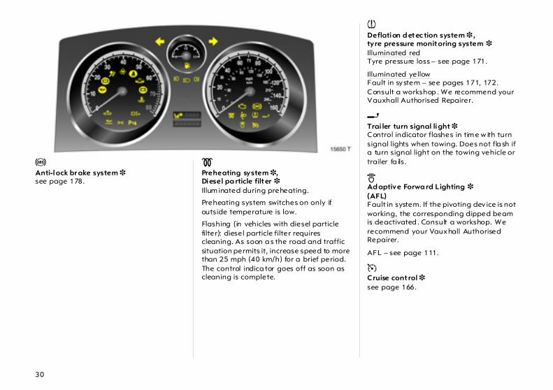
u Anti-lock br ake system 3 see page 178.
! Preheating system 3,Diesel pa rticle filter 3 Illum inated during preheating.
Preheating system switches on only if outside temperature is low.
Flashing (in vehicles with diesel particle filter): diesel particle filter requires cleaning. As soon a s the road and traffic situation permits it, increase speed to more than 25 mph (40 km/h) for a brief period. The control indica tor goes off as soon as cleaning is complete.
w Deflation d etec tion system 3 , tyre pressure monitoring system 3 Illuminated redTyre pressure loss – see page 171.
Illuminated yellowFault in system – see pages 171, 172. Consult a workshop . We recommend your Vauxhall Authorised Repairer.
g Trai ler turn signal light 3 Control indicator flashes in tim e w ith turn signal lights when towing. Does not fla sh if a turn signal light on the towing vehicle or trailer fa ils.
B Ad aptive Forwa rd Lighting 3 (AFL) Fault in system. If the pivoting dev ice is not working, the corresponding dipped beam is deactivated . Consult a workshop. We recommend your Vauxhall Authorised Repairer.
AFL – see page 111.
m Cruise control 3 see page 166.
31
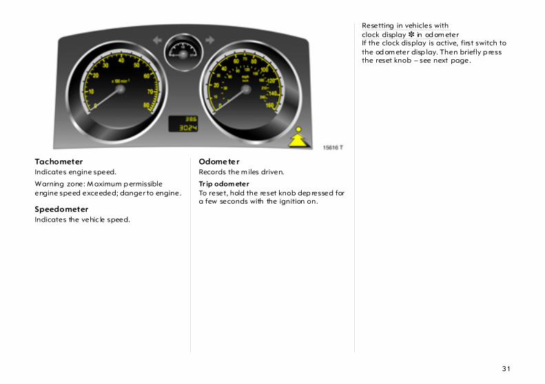
TachometerIndicates engine speed.
Warning zone: M aximum p ermissible engine speed exceeded; danger to engine.
Speedometer Indicates the vehic le speed.
Odometer Records the m iles driven.
Tr ip odom eter To reset, hold the reset knob dep ressed for a few seconds with the ignition on.
Resetting in vehicles with clock display 3 in od om eterIf the clock display is active, first switch to the od om eter disp lay. Then briefly p ress the reset knob – see next page.
32
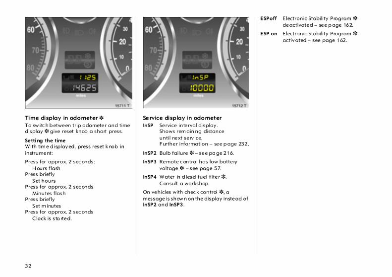
Time display in odometer 3 To sw itc h b etween trip odometer and time display 3 give reset knob a short press.
Setting the time With tim e d isplayed, press reset knob in instrument:
Service display in odometerInSP Service interval d isplay .
Shows rem aining distanceuntil next serv ice.Further information – see p age 232.
InSP2 Bulb failure 3 – see pa ge 216.
InSP3 Remote c ontrol has low battery voltage 3 – see page 57.
InSP4 Water in d iesel fuel filter 3.Consult a workshop.
On vehicles with chec k control 3, a message is show n on the display instead of InSP2 and InSP3.
ESPoff Electronic Stability Program 3deactivated – see p age 162.
ESP on Electronic Stability Program 3activated – see page 162.
Press for approx. 2 sec onds: H ours flash
Press brieflySet hours
Press for approx. 2 sec onds Minutes flash
Press brieflySet m inutes
Press for approx. 2 sec onds C lock is sta rted.
33
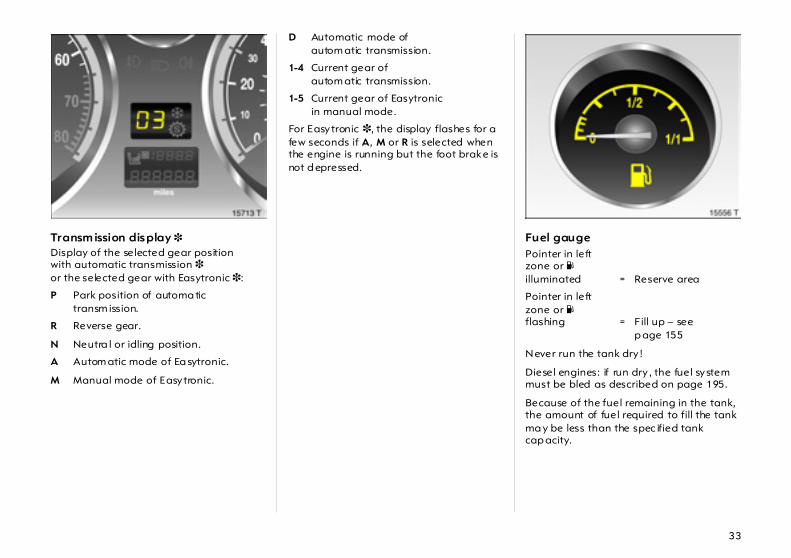
Transm ission display 3Display of the selected gear positionwith automatic transmission 3 or the selected gear with Easytronic 3:
P Park position of automa tic transm ission.
R Reverse gear.
N Neutra l or idling position.
A Autom atic mode of Ea sytronic.
M Manual mode of Easytronic.
D Automatic mode ofautom atic transmission.
1-4 Current gear ofautom atic transmission.
1-5 Current gear of Easytronicin manual mode.
For Easytronic 3, the display flashes for a few seconds if A, M or R is selected when the engine is running but the foot brake is not d epressed.
Fuel gauge
Never run the tank dry !
Diesel engines: if run dry , the fuel system must be bled as described on page 195.
Because of the fuel remaining in the tank, the amount of fuel required to fill the tank ma y be less than the spec ified tank cap acity.
Pointer in left zone or Y illuminated = Reserve area
Pointer in left zone or Y flashing = Fill up – see
p age 155
34
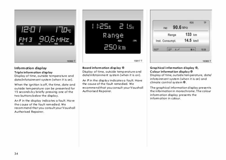
Inform ation display Triple inform ation d isp lay Display of time, outside tempera ture and date/infotainm ent system (when it is on).
When the ignition is off, the time, date and outside tem perature can be presented for 15 second s b y briefly pressing one of the two buttons b elow the displa y.
An F in the display indica tes a fault. Ha ve the c ause of the fault rem edied. We recom mend tha t you consult your Vauxhall Authorised Repairer.
Board inform ation disp lay 3Display of time, outside temp erature a nd date/infotainment system (when it is on).
An F in the disp la y indicates a fault. Have the cause of the fault remedied. We recommend that you consult your Vauxhall Authorised Repairer.
Grap hical infor mation d isplay 3,Colour informat ion displa y 3 Display of time, outsid e tem perature, date/infota inm ent system (when it is on) and climate control system 3 .
The graphical information d isplay presents the information in monochrome. The colour inform ation display presents the inform ation in colour.

35
The type of information and how it is displayed depends on the equipment of the vehicle and the settings of the trip computer 3, clim ate control system 3 and infotainment system 3 .
Some information appea rs in the display in an abb reviated form.
Clim ate control system – see page 127. Infotainm ent system – see infotainment system instructions.
An F in the display indica tes a fault. Ha ve the c ause of the fault rem edied. We recom mend tha t you consult your Vauxhall Authorised Repairer.
Outside temperature A fall in temp erature is indicated immed iately and a rise in temperature after a tim e delay.
If outside temp erature d rops to 3 °C, the symbol : illuminates in the triple information display or the board information display 3 as a warning for icy road surfaces. : rem ains illuminated until temperatures reach a t least 5 °C.
In vehicles with graphical information display 3 or colour information d isplay 3, a warning messa ge is shown in the disp la y a s a warning for icy road surfaces. There is no message below -5 °C.
Caution: The road surface may already be icy even though the display indicates a few deg rees ab ove 0 °C.

36
Triple inform ation display Setting date and timeInfotainm ent system off: p ress Ö and ; below the display as follows:
Correcting time 3 Some RDS transmitters do not send a correct time sig nal. If the incorrect time is continually displa yed, switch off automa tic tim e synchronisation 3 a nd set the tim e manually – see next column.
The automatic setting is indicated by } in the display.
Deactivating/ac tivating autom atic time synchronisation: infotainment system off, press Ö and ; below the display:
Press Ö for ap prox . 2 seconds: Day fla shes
;: Set day
Ö : Month fla shes ;: Set month
Ö : Year flashes;: Set year
Ö : Hours flash;: Set hours
Ö : Minutes flash ;: Set minutes
Ö : Clock is started
Hold down Ö for ap prox . 2 sec. , clock display is now in setting m ode
Press Ö twice (until year flashes)
Press Ö and hold down for approx. 3 seconds until } flashes in display and "RDS TIME" app ears (years flash during this time)
Press ;– displa y shows: RDS TIME 0 = OffPress ;– displa y shows: RDS TIME 1 = On
Press Ö three tim es
37
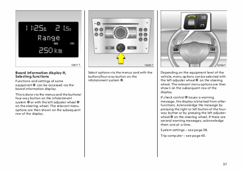
Board information display 3,Selecting functionsFunctions and settings of some equipm ent 3 can be accessed via the board information disp lay.
This is done v ia the menus and the buttons/four-wa y button on the infota inm ent system 3 or with the left adjuster wheel 3 on the steering wheel. The relevant menu options are then shown on the subseq uent row of the display .
Select options v ia the m enus and with the buttons/four-w ay button on the infotainment system 3.
Depending on the equipment level of the vehicle, m enu op tions can b e selected with the left adjuster wheel 3 on the steering wheel. The relevant menu options a re then show n on the subsequent row of the display.
If c heck control 3 issues a warning message, the display is b loc ked from other functions. Acknowledge the message by pressing the right or left button of the four-way button or by pressing the left adjuster wheel 3 on the steering wheel. If there are several warning messages, acknowledge them one at a time.
System settings – see pa ge 38.
Trip comp uter – see pa ge 40.

38
Board information display 3,System settingsPress the Sett ings button on the Infotainm ent system a nd menu points Audio or System are shown.
Press the lower button of the four-way rocker switch to reac h m enu point System. After pressing the right-hand button on the rocker switch, the first function of the System menu is shown.
Some of the functions a ppear on the display in a n abbrev iated form.
The functions are displayed in the following order:
z Time synchronisationz Time, setting hoursz Time, setting minutesz Date, setting dayz Date, setting monthz Date, setting yearz Ignition logicz Language selectionz Setting units of measure
Correc ting time 3 Som e RDS transm itters do not send a correc t time signal. I f the incorrect time is continually displayed, deactivate automatic time synchronisation 3 and set the tim e m anua lly – see next page.

39
The a utomatic setting is indicated by } in the d isplay .
To correct time with the help of R DS, select the m enu item for time synchronisation from the Settings menu.
Make the desired setting.
Setting date and time Select the menu item for time and da te setting from the Settings menu.
Make the desired setting.
The setting is saved when the m enu item is exited.
Ig ni tion logic 3 See infotainment system instructions. Lang uage selection
You can select the d isplay language for some func tions.
Select the menu item for language from the Settings m enu and ma ke the desired setting.
Sett ing units of measureYou can select which units of mea sure are to be used.
Selec t the menu item for units of measure from the Settings m enu and ma ke the desired setting.

40
Board information display 3, Trip computer 3 The trip computer p rov ides information on driving data, which is continually recorded and evaluated electronically .
Access trip computer vehicle data by pressing the BC button on the infotainment system or the left ad juster w heel 3 on the steering wheel.
Some of the functions a ppear on the display in a n abbrev iated form.
Once an audio function has been selected, the subsequent rows of the trip computer func tion are displayed.
The functions are displa yed in the following order:
z Instantaneous consumptionz Average consump tionz Effective consump tionz Average speedz Distance tra velledz Rang ez Stop watch
RangeRange is calculated from current fuel ta nk content and instantaneous consumption. The display shows avera ge values.
After refuelling, the vehic le updates the ra ng e automatically after a brief delay.
If the fuel in the tank will a llow less than 50 km of travel, the wa rning "Range" appea rs on the displa y.
Insta ntaneous c onsump tion Display c hanges depending on sp eed:
Display in g al/h below 8 mph(13 km/h),
Display in m pg below 8 mph(13 km/h).
41
Averag e c onsum ption Display of average consumption. Ca lc ulation can be restarted at any time – see right-hand column.
Effect ive consumpt ion Displays amount of fuel consumed. Measurement can b e restarted at a ny time – see right-hand column.
Averag e sp eed Display of average speed. Calculation can be restarted at any time – see rig ht-hand column.
Stoppag es in the journey with the ignition off are not included in the ca lc ulations.
Distance tra velled Displays num ber of k ilom etres driven. Measurement can b e restarted at a ny time – see right-hand column.
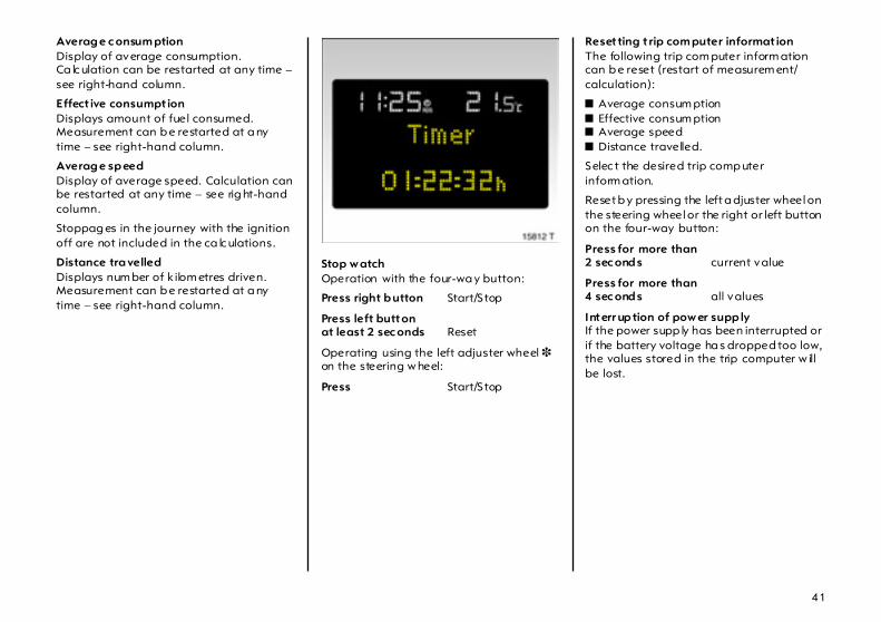
Stop w atchOperation with the four-wa y button:
Press right b utton Start/S top
Press left buttonat least 2 sec onds Reset
Operating using the left adjuster wheel 3 on the steering w heel:
Press Start/S top
Resetting t rip com puter informat ion The following trip com puter inform ation can b e reset (restart of measurem ent/calculation):
z Average consum ptionz Effective consum ptionz Average speedz Distance travelled.
Selec t the desired trip comp uter inform ation.
Reset b y pressing the left a djuster wheel on the steering wheel or the right or left button on the four-way button:
Press for more than2 sec ond s current value
Press for more than4 sec ond s all values
Interr up tion of pow er supp ly If the power supp ly has been interrupted or if the battery voltage ha s dropped too low, the values stored in the trip computer w ill be lost.
42
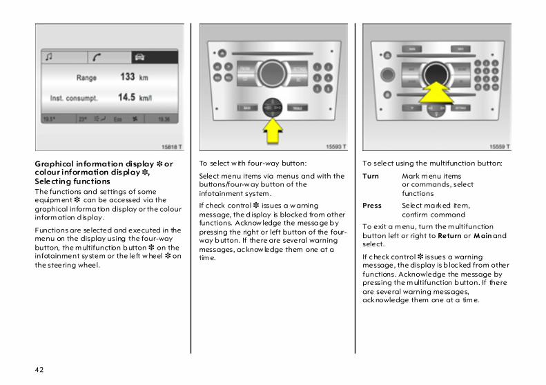
Graphical information display 3 or colour information display 3,Selecting functionsThe functions and settings of some equipm ent 3 can be accessed via the graphical informa tion display or the colour inform ation d isplay .
Functions are selected and executed in the menu on the display using the four-way button, the m ultifunction b utton 3 on the infotainment system or the left w heel 3 on the steering wheel.
To select w ith four-way button:
Select menu items via menus and with the buttons/four-w ay button of the infotainment system .
If check control 3 issues a w arning message, the d isplay is blocked from other functions. Acknow ledge the messa ge b y pressing the right or left button of the four-way b utton. If there are several warning messages, ac know ledge them one at a tim e.
To select using the multifunction button:
Turn Mark m enu itemsor commands, selectfunctions
Press Select ma rked item,confirm command
To exit a m enu, turn the m ultifunction button left or right to Return or M ain and select.
If c heck control 3 issues a warning message, the display is b loc ked from other functions. Acknowledge the message by pressing the m ultifunction b utton. If there are several warning messages, acknowledge them one at a tim e.
43
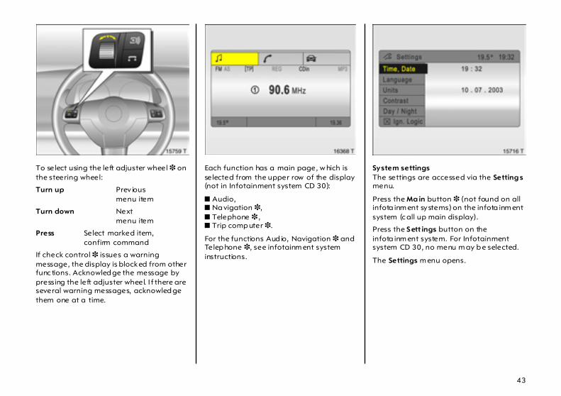
To select using the left adjuster wheel 3 on the steering wheel:
Turn up Prev iousmenu item
Turn down Nextmenu item
Press Select marked item,confirm command
If check control 3 issues a warning message, the display is blocked from other func tions. Acknowled ge the message by pressing the left adjuster wheel. I f there are several warning messages, acknowled ge them one at a time.
Each function has a main page, w hich is selected from the upper row of the display (not in Infotainment system CD 30):
z Audio, z Na vigation 3, z Telephone 3 , z Trip comp uter 3.
For the functions Aud io, Navigation 3 and Telep hone 3, see infotainm ent system instructions.
System settings The settings are accessed via the Setting s menu.
Press the Ma in button 3 (not found on all infota inm ent systems) on the infota inm ent system (c all up main display).
Press the S ett ings button on the infota inm ent system. For Infotainment system CD 30, no menu m ay b e selected.
The Settings m enu opens.

44
Setting date and timeSelect menu item Time, Date from the Setting s menu.
The m enu for Time, Date is displayed.
Select the menu items required.
Make the desired setting.
Correcting time 3 In systems with GPS receiver1), date and tim e a re set a utoma tica lly upon receipt of a GPS satellite signal. If the displayed tim e does not match local time, it can be corrected manually or automatically by receiving an RDS tim e signal2) 3.
Some RDS tra nsmitters do not send correct tim e signals. If the incorrect time is displayed often, deactivate autom atic tim e synchronisation 3 a nd set the tim e manually.
To correct tim e with the help of RDS, select menu item Synchron.clock autom atical from the Time, Da te menu.
The box in front of Synchron.clock automat ical will be ticked , see Fig. 15721 T.
Languag e selectionYou can select the display language for some functions.
Selec t menu item Language from the Sett ings menu.
The available languages are displayed.
1) GP S = Global Pos itioning System,Satellite system for wo rld-wide pos itioning.
2) RDS = Radio Data System.
45
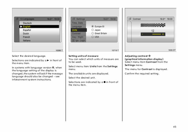
Select the desired language.
Selections are indicated by a 6 in front of the m enu item .
In systems with language version 3, when the la nguage setting of the display is changed , the system will ask if the m essag e language should also be changed – see infotainment system instructions.
Setting units of m easur eYou can select which units of measure are to be used .
Select menu item U nits from the S et tings menu.
The ava ilab le units are displayed.
Select the desired unit.
Selections are indicated by a o in front of the menu item.
Ad just ing contra st 3(grap hical inform ation d isplay) Selec t menu item Contrast from the Sett ings menu.
The menu for Contr ast is disp layed .
Confirm the required setting .

46
Setting displa y mod e 3 The displa y ca n be adjusted to suit the light conditions, black or coloured text on a light background or white or coloured text on a dark background.
Select menu item Day/N ight from the Setting s menu.
The options are displayed.
Autom atic: adapted based on vehicle lighting .
Alw ays day design: black or coloured text on light backg round.
Alw ays night design: white or coloured text on dark b ackground .
Selections are indicated by a o in front of the m enu item .
Ig ni tion logic 3 See infotainment system instructions.
Graphical information display 3 or Colour information display 3, Trip computer 3 The trip computers provide information on driving data, which is continually recorded and evalua ted electronically.
The trip computer main page provides information on range and instantaneous consumption.
To display other trip computer data, press the BC button on the infotainment system 3, select the trip computer menu front the display or press the left adjuster wheel 3 on the steering wheel.
Ra ng eRange is calculated from current fuel tank content and instantaneous consumption. The display shows average values.
After refuelling, the vehicle updates the range automatically a fter a brief delay .

47
If the fuel in the tank will allow less tha n 30 miles (50 km) of travel, the warning "Range" ap pears on the d isplay .
Acknowled ge the menu item as desc rib ed on page 42.
Instantaneous consump tion Display changes depending on speed :
Display in gal/h below 8 mph(13 km/h),
Display in mp g below 8 mph(13 km/h).
Distance travelled Displays number of kilometres driven. Measurement can be restarted at any tim e – see next page.
Average speed Average speed calculation. Measurement can be restarted a t any time – see next page.
Stoppages in the journey with the ignition off are not includ ed in the calculations.
Effective consum ption Displays a mount of fuel consumed . Measurement can be restarted at any tim e – see next page.
Average consumpt ion Calculation of avera ge c onsumption. Measurement can be restarted at any tim e – see next page.
Resetting t rip com puter informat ion The following trip com puter inform ation can b e reset (restart measurements):
z Distancez Average speedz Effective consum ptionz Average consum ption
Selec t BC 1or BC 2 from the trip computer menu.
48
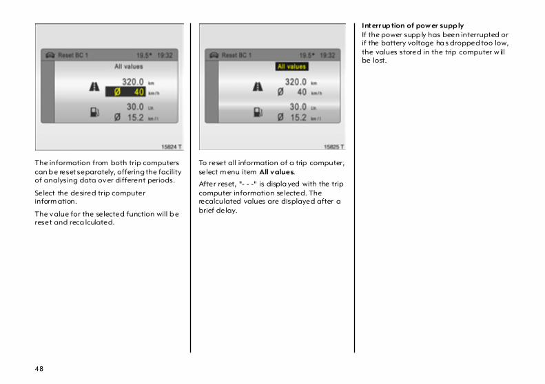
The information from both trip computers can b e reset separately, offering the facility of analysing data over different periods.
Select the desired trip computer inform ation.
The value for the selected function will b e reset and reca lculated.
To reset all information of a trip computer, select m enu item All values.
After reset, "- - -" is displa yed with the trip computer information selected. The recalculated values are displayed after a brief delay.
Interr up tion of pow er supp ly If the power supp ly has been interrupted or if the battery voltage ha s dropped too low, the values stored in the trip computer w ill be lost.

49
Stop watchSelect menu item Timer from the Board Com puter menu.
The Tim er menu opens.
To start, selec t menu item Start.
To reset, selec t menu item Reset .
Stop watch settings can be ma de v ia the Opt ions menu 3 :
Dr iving Time excl. S topsThe time the vehicle is in m otion is recorded . Stationary tim e is not includ ed.
Dr iving Time incl. S tops The time the vehicle is in m otion is recorded . The tim e the vehicle is sta tionary with the key in the starter sw itc h is included.
Tr avel TimeMeasurement of the time from manual activation via Sta rt to manual deactivation via Reset .
Display of current tyre pressure 3 Selec t menu item Tyr es from the Board Computer m enu.
The current pressure of eac h ty re is displayed.
Further information – see page 172.
50
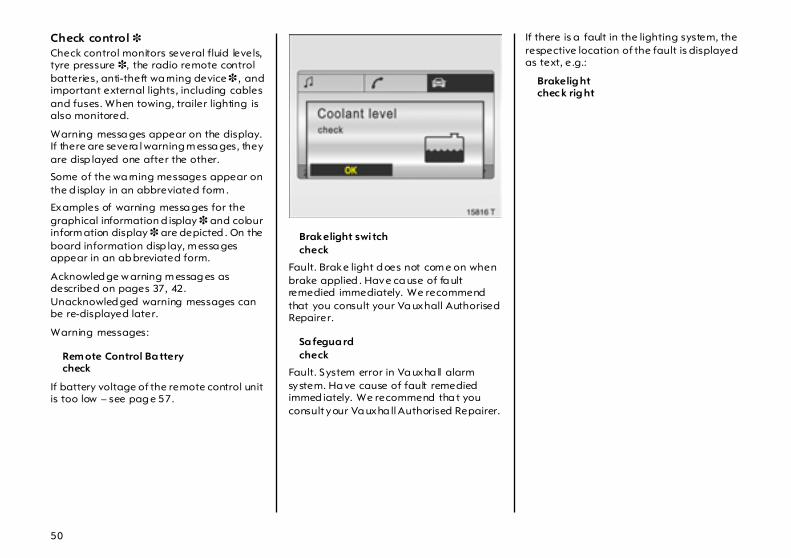
Check control 3 Check control monitors several fluid levels, tyre pressure 3, the radio remote control batteries, anti-theft wa rning device 3 , and important external lights, including cables and fuses. When towing, trailer lighting is also monitored.
Warning messa ges appear on the display. If there are severa l warning m essa ges, they are disp layed one after the other.
Some of the wa rning messages appear on the d isplay in an abbreviated form .
Examples of warning messa ges for the graphical information d isplay 3 and colour inform ation display 3 are depicted . On the board information disp lay, m essa ges appear in an ab breviated form.
Acknowled ge w arning m essag es as described on pages 37, 42. Unacknowled ged warning messages can be re-displayed later.
Warning messages:
Rem ote Control Ba tterycheck
If battery voltage of the remote control unit is too low – see pag e 57.
Brakelight swi tchcheck
Fault. Brake light d oes not com e on when brake applied . Have ca use of fa ult remedied immediately. We recommend that you consult your Va uxhall Authorised Repairer.
Sa fegua rdcheck
Fault. System error in Va uxha ll alarm system. Ha ve cause of fault remedied immed iately. We recommend tha t you consult your Va uxha ll Authorised Repairer.
If there is a fault in the lighting system, the respective location of the fault is displayed as text, e.g.:
Brakelig htchec k rig ht

51
In vehicles with tyre pressure monitoring system 3, if tyre pressure is too low, the display indicates which tyre to check, e.g .:
Tyre pressurecheck rear rig ht tyre (va lue in bar)
Check ty re pressure at next opportunity using suitable gauge. Tyre pressure monitoring system 3 – see page 172. Checking tyre pressure – see p age 265.
In vehicles with tyre pressure control system 3, if there is major loss of pressure in a ty re, the display indicates the tyre at fault, e.g.:
Atent ion!Rea r left tyre pressur e loss (value in b ar)
Stop im med ia tely a nd check tyre. Tyre pressure monitoring system 3 – see page 172.
Wash fluid levelcheck
Fluid level in wind screen wash system too low . Topping up w ash fluid – see pag e 241.
Rear w indow wash system and headlight wash system 3 a re deactivated if wash fluid level is low .
Coolant levelcheck
Fluid level in engine cooling system is low. Check coolant level immediately – see page 236.
Interruption of p ower supply Stored w arning messa ges appear on the display one a fter the other.
52
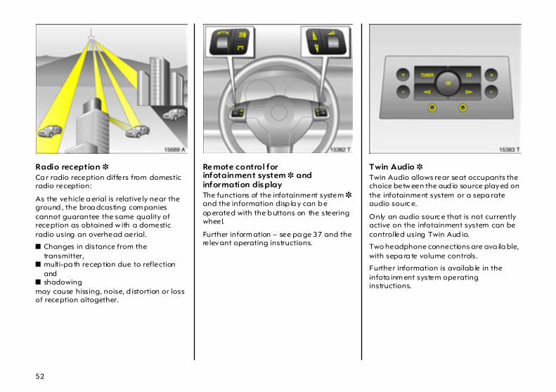
Radio reception 3 Ca r radio reception differs from domestic radio reception:
As the vehicle a erial is relatively near the ground , the broa dcasting com panies cannot guarantee the same quality of reception as obtained w ith a domestic radio using an overhead aerial.
z Changes in distance from the transmitter,
z multi-pa th recep tion due to reflection and
z shadowing may cause hissing, noise, d istortion or loss of reception altogether.
Remote control for infotainment system 3 andinformation displayThe functions of the infotainment system 3 and the information disp la y can b e op erated with the b uttons on the steering wheel.
Further inform ation – see pa ge 37 and the relevant operating instructions.
Twin Audio 3 Twin Audio allows rear seat occupants the choice betw een the aud io source played on the infotainment system or a sepa rate audio sourc e.
Only an audio sourc e that is not currently active on the infotainment system can be controlled using Twin Aud io.
Two headphone connections are ava ila ble, with sepa ra te volume controls.
Further information is availab le in the infota inm ent system operating instructions.
53
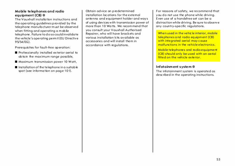
Mobile te lephones and radio equipment (CB) 3 The Vauxhall installa tion instructions and the operating guidelines p rov id ed by the telephone manufa cturer m ust be observed when fitting and operating a m ob ile telephone. Failure to d o so could invalida te the vehicle’s operating perm it (EU Directive 95/54/EG).
Prerequisites for fault-free op eration:
z Professionally installed exterior aerial to ob ta in the maximum range possible,
z Maximum transmission power 10 Watt,
z Installation of the telephone in a suitab le spot (see informa tion on pag e 101).
Obtain ad vice on p redetermined installation loc ations for the external antenna and equipment holder and ways of using dev ices w ith transmission power of more than 10 Wa tts. We recom mend that you consult your Vauxhall Authorised Repairer, who will have brackets and various installation k its available as accessories and will install them in accordance with regulations.
For reasons of safety, we recommend that you d o not use the phone while driving. Even use of a handsfree set can be a distraction while driving. Be sure to observe any country-specific regulations.
Infotainm ent system 3 The infotainment system is operated as desc ribed in the operating instructions.
When used in the vehic le interior, mobile telephones a nd radio eq uipm ent (CB) with integrated aerial may c ause malfunctions in the vehicle electronics.
Mobile telephones and ra dio equipment (CB) should only be used with an aerial fitted on the vehicle exterior.

54
Keys, Doors,Bonnet
Replacement keys The key is a c onstituent of the electronic immobiliser. Ordering keys from a Vauxhall Authorised Repairer g uarantees problem -free op eration of the electronic immobiliser.
Keep the sp are key in a safe spot.
Locks, see pa ge 247.
Key with foldaway key section 3 Press button to extend. Press button to retract; key section engages audibly.
Child safety locks
Using key or screw driver, turn lever on rear door lock from the vertical position: d oor cannot then be opened from inside.
Use the child safety lock whenever child ren are occupying the rear seats. Disregard may lea d to injuries or endanger life. Vehicle p assengers should be informed accordingly.

55
Electronic imm obiliser The system checks whether the vehicle m ay be sta rted using the key that has been inserted. If the key is recognised as "authorised" the vehicle can be started. The c heck is carried out via a transponder housed in the key.
The electronic imm ob iliser activates automatically when the key is removed from the starter switch.
Control ind icator for imm obiliser Control indica tor A illuminates briefly after the ig nition is sw itc hed on.
If the control indicator flashes w hen the ignition is on, there is a fault in the system; the engine cannot be started. Switc h off the ignition and then rep eat the start attempt.
If control indicator A continues to flash, try to start the eng ine using the spare key and consult a workshop. We recomm end your Vauxhall Authorised Repairer.
If control indica tor A illuminates after the eng ine is started, there is a fault in the eng ine electronic s – see page 160.
Note The immobiliser does not lock the doors. Therefore, after leaving the vehicle a lways lock it and switch on the Vauxhall alarm system 3 – see p ages 58, 63.
The Car Pass contains all of the vehicle’s data and should therefore not be kept in the vehicle.
Have your Car Pass on hand when consulting a Vauxhall Authorised Repa irer.
56
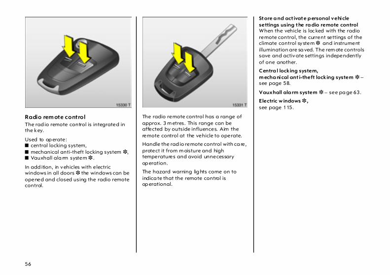
Radio rem ote control The rad io remote control is integrated in the key.
Used to op erate:z central locking system, z mechanical anti-theft locking system 3, z Vauxhall ala rm system 3 .
In add ition, in vehicles with electric windows in all doors 3 the windows can be opened and closed using the radio remote control.
The radio remote control has a range of approx. 3 m etres. This range can be affected by outside influences. Aim the remote control at the vehicle to operate.
Handle the rad io remote control with ca re, protect it from m oisture and high temperatures and avoid unnecessary op eration.
The hazard warning lig hts come on to indica te that the remote control is op erational.
Store a nd act ivate p ersonal vehicle settings using the ra dio remote control When the vehicle is loc ked with the radio remote control, the current settings of the climate control system 3 and instrument illumination are sa ved. The rem ote controls save and activate settings independently of one another.
Centra l locking system,m echa nical ant i-theft locking system 3 – see page 58.
Vauxhall ala rm system 3 – see pa ge 63.
Electric w indows 3 , see page 115.
57
Fault If the central locking system cannot be opera ted with the radio rem ote control, it may be due to the follow ing:
z The range of the radio remote control has been exceed ed.
z Radio rem ote control battery voltage is too low. Battery replacement – see next page.
z Freq uent, rep eated opera tion of the ra dio remote control outside the recep tion range of the vehicle (e.g. too far from vehicle, remote control is then no longer recognised). R emote control synchronisation – see next pag e.
z If the centra l loc king system is overloaded as a result of repeated op eration at short intervals. The power supply is c ut off for a b rief period.
z Interference from higher-power radio waves from other sources.
To eliminate the cause of the fault, contact your Vauxhall Authorised R epairer.
Open driver’s door with key – see next pages.
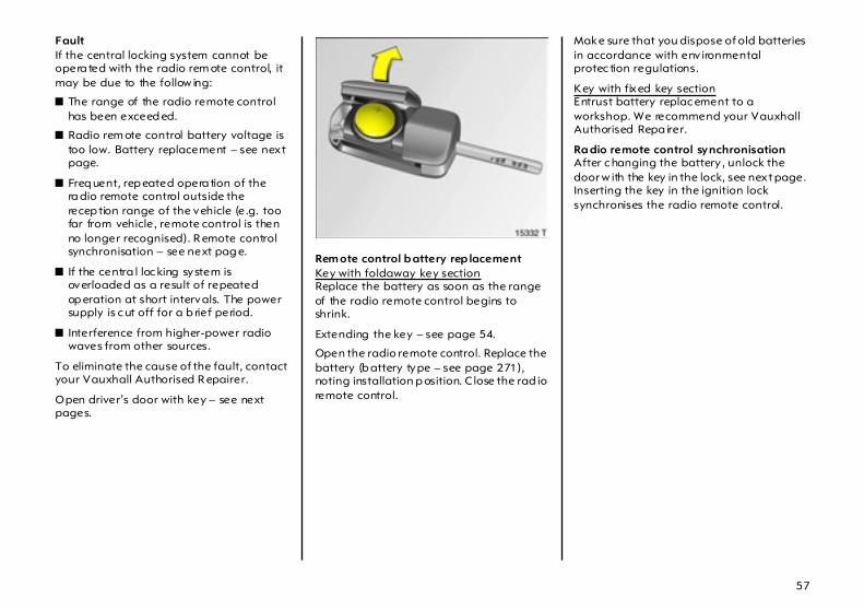
Rem ote control b attery rep lacement Key with foldaway key sectionReplace the battery as soon as the range of the radio remote control begins to shrink.
Extending the key – see page 54.
Open the radio remote control. Replace the battery (b attery type – see page 271), noting installation p osition. C lose the rad io remote control.
Make sure that you dispose of old batteries in accordance with env ironmental protec tion regulations.
Key with fixed key sectionEntrust battery replac ement to a workshop. We recommend your Vauxhall Authorised Repa irer.
Ra dio remote control synchronisation After c hanging the battery , unlock the door w ith the key in the lock, see next page. Inserting the key in the ignition lock synchronises the radio remote control.
58
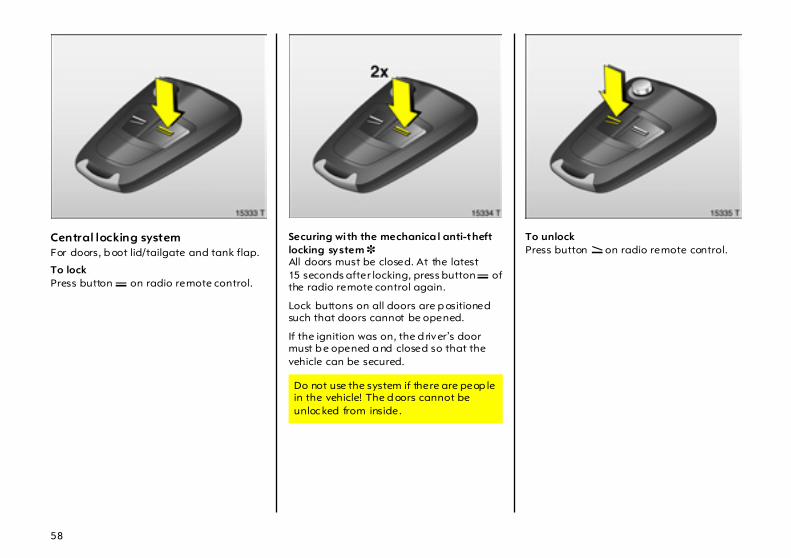
Central locking system For doors, b oot lid/tailgate and tank flap.
To lock Press button p on radio remote control.
Securing wi th the mechanica l anti-theft locking system 3 All doors must be closed. At the latest 15 seconds after locking, press button p of the radio remote control again.
Lock buttons on all doors are p ositioned such that doors cannot be opened.
If the ignition was on, the d river’s door must b e opened a nd closed so that the vehicle can be secured.
To unlock Press button q on radio remote control.
Do not use the system if there are peop le in the vehicle! The d oors cannot be unloc ked from inside.

59
Centra l locking switc h for locking and unlocking the doors from insid e the vehiclePress button m in the centre console: doors are locked or unlocked.
If the key is in the ignition, locking is only possible if all doors are closed.
When the mechanical anti-theft locking system 3 is active – see previous page – the doors cannot be unlocked with this button.
Note z If the driver’s door is not closed p roperly,
the central locking system will not loc k.
z To lock the doors from within (e.g. to prevent unwanted entry from outside), press central lock ing switch m in the centre console.
z After unlocking with the key in the lock and opening the driver’s door, the entire vehicle is unloc ked.
z If the central lock ing system is loc ked, the doors ca n also be unlocked by p ulling the interior handle. This unlocks the central locking system .
z Locked doors become unlocked autom atically on an ac cident of more tha n a particular severity level (for external help), also the hazard warning lights come on. For this the key must be in the ignition.
z The LED in the central locking switch m comes on for around 2 minutes after loc king .

60
Oper ating the w indows 3 from outside
On vehicles w ith electric wind ow s in all doors, the windows can b e opened or closed from outside:
Hold button q or p on the rad io remote control depressed until all windows have op ened or completely c losed .
Further inform ation on w indows – see page 115.
Overload The power supply is cut off for a brief period if the central locking system is repeatedly operated at short intervals.
The system is protected by a fuse in the fuse box – see page 212.
Further information on windows with electric drive – see page 117.
Ta ke c are when operating the electric wind ows. Risk of injury, particula rly to children.
Vehicle passengers should be informed according ly .
Keep a close watch on the wind ow s when closing them. Ensure tha t nothing becomes trapp ed in them as they move.
61
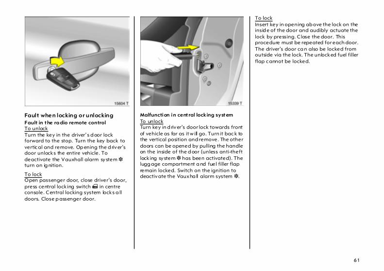
Fault when locking or unlocking Fault in the ra dio remote control To unlockTurn the key in the driver’s d oor lock forward to the stop. Turn the key back to vertic al and remove. Op ening the d river’s door unlocks the entire vehicle. To deactivate the Vauxhall alarm system 3 turn on ig nition.
To lockOpen passenger door, close driver’s door, press central lock ing switch m in centre console. Central locking system locks a ll doors. Close p assenger door.
Malfunction in central locking system To unlockTurn key in d river’s door lock towards front of vehicle as far as it w ill go. Turn it bac k to the vertical position and remove. The other doors can be opened by pulling the handle on the inside of the d oor (unless anti-theft lock ing system 3 has been activated). The lugg age compartment a nd fuel filler flap remain locked. Switch on the ignition to deactivate the Vauxha ll alarm system 3.
To lockInsert key in opening ab ove the lock on the insid e of the door and audibly actuate the lock by pressing. C lose the door. This procedure must be repeated for each door. The driver’s door ca n also be locked from outside via the lock. The unlocked fuel filler flap c annot be locked.

62
Luggage compartment To unlock Press button q on the rad io remote control. The luggage comp artm ent is unlocked together with the central locking system a nd can be opened by pulling the button under the handle.
To lock Press button p on radio remote control.
Open luggag e c om partmentThere is a handle on the inside of the tailgate for closing the luggage compa rtm ent.
Fitting of accessories on the tailgate will increa se its weight. I f it becomes too heavy, the tailgate w ill then not stay open.
Do not drive with the tailgate open or ajar, e.g. w hen transporting bulky objects, sinc e toxic exhaust gas could penetra te the interior.

63
Vauxhall alarm system 3 monitors
z the doors, luggage compartment, bonnet,
z the passenger c om partment,
z vehicle tilt, e.g. if it is raised,
z the ignition.
To activate All d oors, windows, the sun roof 3 and the bonnet must be closed. Within 15 seconds of lock ing, press button p on the radio remote control ag ain.
If the ignition wa s switched on, the driver’s door must b e opened a nd closed so that the Vauxhall a la rm system can b e switched on.
Act ivat ion without monitoring of pa ssenger comp artment a nd vehicle ti lt e.g. if anim als a re to be left in the vehic le.
1. Close tailgate and b onnet.
2. Press b utton b in the roof console. The LED in b utton m flashes (max. 10 seconds) – see next page.
3. Close doors.
4. Switch on Vauxhall alarm system . LED illuminates. After approx. 10 seconds the system is activated, without monitoring of the p assenger compa rtm ent or vehicle tilt. LED flashes until system is switched off.

64
Light emit ting d iode (LED) During the first 10 seconds of Vauxhall alarm system activation:
z LED illum inated = Test, switch-on delay ,
z LED flashes q uick ly = Luggage compartment door,or bonnetop en,System error.
After the first 10 second s of Vauxhall alarm system activation:
z LED flashes slow ly = Systemengaged
z LED illuminates forapprox . 1 second = Switch-off
If a system fa ult occ urs, consult a workshop. We recom mend your Vauxhall Authorised Repairer.
To deact ivate Press b utton q on the radio remote c ontrol– or –switch on the ignition.

65
In the event of a fault in the rad io remote control, open the vehicle with the key : Insert key in lock and turn tow ards front of vehic le as far as it w ill go. Return key to the vertic al position and remove.
If the alarm is triggered when the driver’s door is opened, deactivate the Vauxhall alarm system by switching on the ignition.
Alarm While the Vauxhall alarm system is switched on the alarm can be triggered: z an acoustic sig nal (horn) and z a v isual signal (hazard w arning lights).
The number and duration of the alarms are legally established.
The alarm can b e interrupted by pressing a button on the ra dio remote control or by sw itc hing on the ignition. Pressing button q or switching on the ig nition will deactivate the Vauxhall alarm system at the sam e time.
66
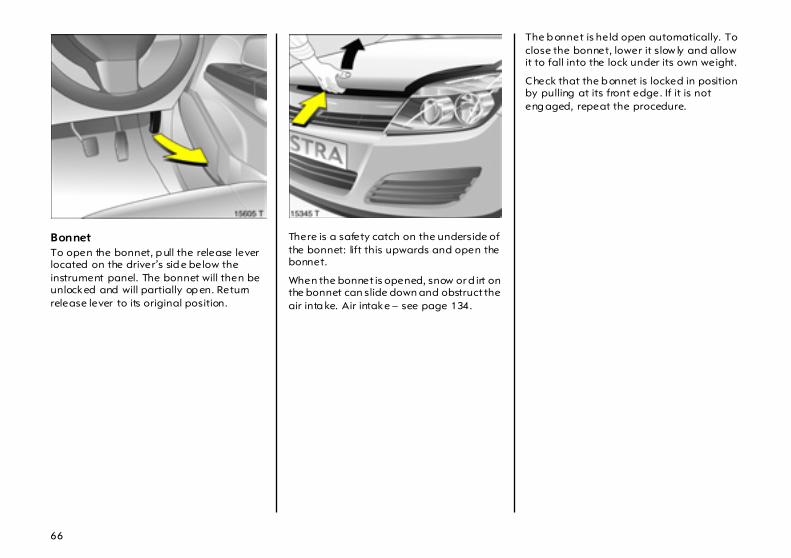
Bonnet To open the bonnet, p ull the release lever located on the driver’s sid e below the instrument panel. The bonnet will then be unlocked and will partially op en. Return release lever to its original position.
There is a safety catch on the underside of the bonnet: lift this upwards and open the bonnet.
When the bonnet is opened, snow or d irt on the bonnet can slide down and obstruct the air inta ke. Air intake – see page 134.
The b onnet is held open automatically. To close the bonnet, lower it slow ly and allow it to fall into the lock under its own weight.
Check that the b onnet is locked in position by pulling at its front edge. If it is not eng aged, repeat the procedure.

67
Seats, Interior Front seat adjustmentsee p ages 5, 6.
Adjusting 3 the rear row of seatssee p age 67.
Luggage compartment enlargem ent see p ages 70, 71, 73.
Seat pos ition Adjust driver’s sea t such that with the driver sitting upright the steering wheel is held in the area of its upper spokes with the driver’s arms slig htly bent.
Push p assenger seat as far b ack as possible.
The seat back rests m ust not be tilted too far ba ck (recom mended tilting angle app rox . 25° ).
Failure to observe the descriptions can lead to injuries which could be fatal. Vehic le pa ssengers should be informed accordingly before mov ing away.
68
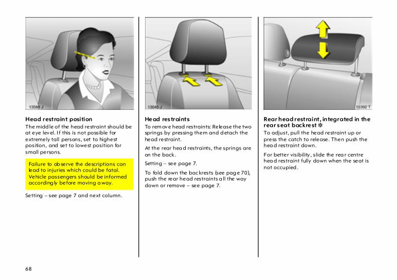
Head restraint position The midd le of the head restraint should be at eye level. I f this is not possible for extremely tall persons, set to highest position, and set to lowest position for small persons.
Setting – see page 7 and next column.
Head restraints To rem ove head restraints: Release the two springs by pressing them and d etach the head restraint.
At the rear hea d restraints, the springs are on the back .
Setting – see page 7.
To fold down the bac krests (see pag e 70), push the rear head restraints a ll the way down or remove – see page 7.
Rear head restraint, integrated in the rear seat backrest 3 To adjust, pull the head restraint up or press the catch to release. Then push the hea d restraint down.
For better visibility , slide the rea r centre hea d restraint fully down when the seat is not occupied .
Failure to ob serve the descriptions can lead to injuries which could be fatal. Vehicle passengers should be informed according ly before moving a way.

69
Armrest 3 at driver’s seat Push raised armrest backward aga inst resista nce and fold down.
The a rm rest can be moved to different positions in stag es by lifting it.
Adjusting the rear row of seats 3 Raise the handle below the sea t the slide the seat b ench to the d esired p osition.
Release the handle and engage the seat bench.
Arm rest 3 in the rear backrest Fold down the armrest, pulling the strap obliquely down (45°).
When the centre rear seat is in use or the rear backrests are folded, fold the a rm rest up.
A flap loca ted b ehind the arm rest facilitates transport of long, narrow objects – see page 74.
70
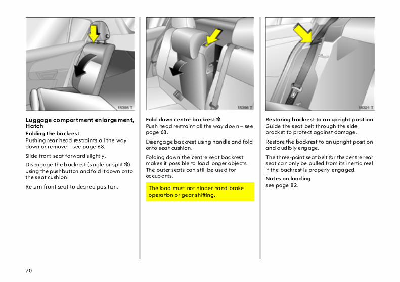
Luggage compartment enlargement,Hatch Folding the ba ckrest Pushing rea r head restraints all the way down or remove – see page 68.
Slide front seat forward slightly .
Disengage the b ackrest (single or split 3) using the pushbutton and fold it down onto the seat cushion.
Return front seat to desired position.
Fold down centre ba ckrest 3Push head restraint all the way d ow n – see page 68.
Disenga ge ba ckrest using handle and fold onto sea t cushion.
Folding down the centre seat bac krest makes it possible to loa d long er objects. The outer seats can still be used for oc cup ants.
Restoring b ackrest to a n up right p osit ion Guide the seat belt through the side bracket to protect against damage.
Restore the backrest to an upright position and a ud ib ly eng age.
The three-point seat b elt for the c entre rear seat ca n only be pulled from its inertia reel if the backrest is properly enga ged.
Notes on load ing see page 82. The load must not hinder ha nd brake
opera tion or gear shifting.
71
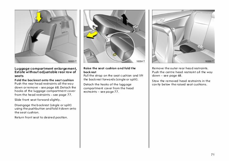
Luggage compartment enlargement,Estate without adjustable rear row of seats Fold the bac krest onto the sea t cushion Push the rear head restraints all the wa y down or remove – see page 68. Detach the hooks of the luggage compartment cover from the head restraints – see page 77.
Slide front seat forward slightly .
Disengage the b ackrest (single or split) using the pushbutton and fold it down onto the seat cushion.
Return front seat to desired position.
Raise the seat cushion a nd fold the backrest Pull the strap on the seat c ushion and lift the back rest forwa rd s (single or split).
Detach the hooks of the lugg age compartment cover from the head restra ints – see pa ge 77.
Remove the outer rear hea d restraints. Push the centre head restra int a ll the way down – see page 68.
S tow the removed head restraints in the cav ity below the raised seat cushions.

72
Disengage the b ackrest (single or split) using the pushbutton, fold it forward and enga ge.
Fold down centre ba ckrest 3Push head restraint all the way d ow n – see page 68.
Disenga ge ba ckrest using handle and fold onto sea t cushion. If the seat cushion is ra ised, fold it forward until it eng ages.
Folding the centre seat back rest makes it possible to load long er objects. The outer seats can still b e used for occupants.
Restoring the b ackrests or seat cushions 3 to their original position Guide the seat belt through the side bracket to protect against damage.
To restore the back rest to an upright position, fold up , pressing the button on the ba ckrest. Audibly enga ge the ba ckrest in an upright position.
The load must not hinder ha nd brake opera tion or gear shifting.

73
Raised seat cushions: Insert and ad just head restraints in bac krests (see pages 7, 68). Fold ba ck seat c ushions, mak ing sure the belt buckles a re properly positioned.
Attach the hooks of the luggag e compartment cover to the hea d restraints – see page 77.
The three-point seat belt for the centre rear seat can only be pulled from its inertia reel if the b ackrest is properly engag ed.
Safety net 3 see page 78.
Notes on load ing see page 82.
Luggage compartment enlargement,Estate w ith adjustable rear row of seats Fold backrests onto seat c ushions Push the rear head restraints all the way down or rem ove – see page 68. Detach the hooks of the lugg age com partment c over from the hea d restraints – see page 77.
Slide front seat forward slightly.
Disenga ge the back rest (single or split) using the sliders and fold it down onto the seat cushion.
Return front sea t to desired position.
Ra ise the seat cushion and fold the ba ckrest Lift rear sea t cushions forward, single or split.
Detach the hooks of the luggage compa rtm ent cover from the head restraints – see page 77.

74
Remove the outer rear head restraints. Push the centre head restraint all the way down – see page 68.
Stow the rem oved head restraints in the cavity below the raised seat cushions.
Disenga ge the back rest (single or split) using the sliders, fold it forwa rd and engage.
Loading op tion behind the armrest in the rear seat b ackrest 3 Fold down the armrest, pulling the strap obliquely down (45°).
Pull the handle and fold down the cover.
Folding down the c over ma kes it possib le to load long, na rrow ob jects. The outer seats can still be used for occupants.
To restore, fold the arm rest back in position.
The load m ust not hinder hand b ra ke operation or gear shifting.
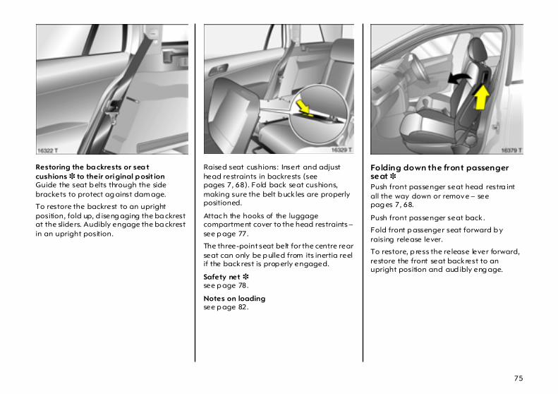
75
Restoring the ba ckrests or sea t cushions 3 to their original p osit ion Guide the seat b elts through the side brackets to protect ag ainst dam age.
To restore the backrest to an upright position, fold up, d iseng aging the ba ckrest at the sliders. Audibly engage the ba ckrest in an upright position.
Raised seat cushions: Insert and adjust head restraints in backrests (see pages 7, 68). Fold back seat cushions, making sure the belt b uck les are properly positioned.
Attac h the hooks of the luggage compartment cover to the head restraints – see p age 77.
The three-point seat belt for the centre rear seat can only be p ulled from its inertia reel if the back rest is prop erly engaged.
Safety net 3 see p age 78.
Notes on loading see p age 82.
Folding down the front passenger seat 3 Push front passenger seat head restra int all the way down or remove – see pag es 7, 68.
Push front passenger seat back .
Fold front p assenger seat forward b y raising release lever.
To restore, p ress the release lever forward, restore the front seat back rest to an upright position and aud ibly eng age.
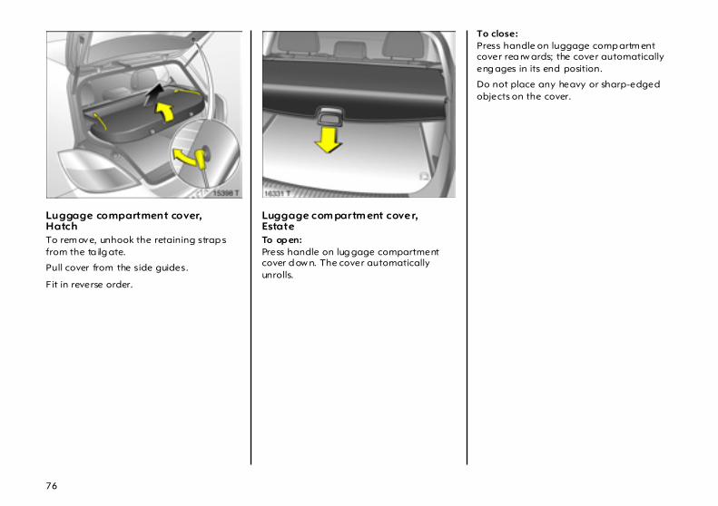
76
Luggage compartment cover,Hatch To rem ove, unhook the retaining strap s from the ta ilg ate.
Pull cover from the side guides.
Fit in reverse order.
Luggage com partm ent cover,Estate To op en: Press handle on lug gage compartment cover d ow n. The cover automatically unrolls.
To close: Press handle on luggage comp artm ent cover rea rw ards; the cover automatically eng ages in its end position.
Do not place any heavy or sharp-edged objects on the cover.

77
To cover the ga p betw een the luggage compartment cover and the rear back rests, there is a c over on the cartridge. Attach the two hooks of the cover to the head restraint guid e rods. If the safety net is mounted, run the hooks throug h the net mesh.
Rem oving Open the luggage compa rtm ent c over and detach the hooks from the head restraints.
Move release lever on right side of lug gage compartment cover upwa rd . Lift rig ht cover a nd remove from brac kets.
Fitting Insert the lug gage compartment cover in the recess on the left, press the release lever on the right side upward, insert the cover in the recess on the right, engage and p ress the lever down.
Attach the hooks on the head restraints – see Fig. 16332 T.
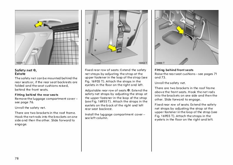
78
Safety net 3,Estate The safety net can b e mounted behind the rea r seats or, if the rear seat backrests are folded and the seat cushions ra ised, behind the front seats.
Fitting behind the rear sea tsRemove the luggage compartment cover – see page 76.
Unroll the safety net.
There are two brackets in the roof fram e. Hook the net rods into the b ra ckets on one side a nd then the other. Slide forward to enga ge.
Fixed rear row of seats: Extend the safety net stra ps by ad justing the strap at the up per fastener in the loop of the strap (see Fig. 16955 T). Attach the straps in the eyelets in the floor on the right a nd left.
Ad justable rear row of seats 3: Extend the safety net straps by adjusting the strap at the upper fastener in the loop of the strap (see Fig. 16955 T). Attach the straps in the eyelets on the b ack of the rig ht and left rear seat backrest.
Install the lug gage compartment cover – see left column.
Fitting behind front seats Raise the rea r seat cushions – see pages 71 and 73.
Unroll the safety net.
There are two brackets in the roof fra me above the front seats. H ook the net rod s into the brackets on one side and then the other. Slide forwa rd to engage.
Fixed rear row of seats: Extend the safety net straps by adjusting the strap at the upper fastener in the loop of the strap (see Fig. 16955 T). Attach the straps in the eyelets in the floor on the right and left.
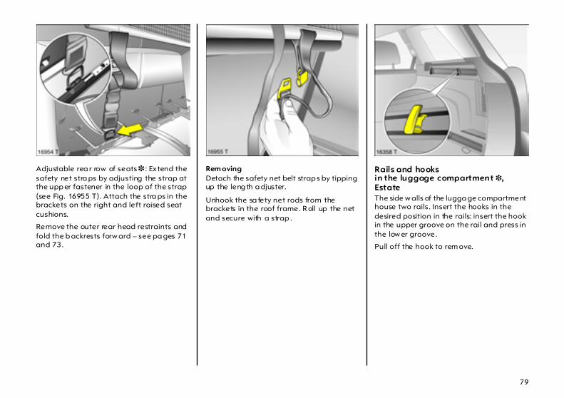
79
Adjustable rea r row of seats 3 : Extend the safety net stra ps by adjusting the strap at the upp er fastener in the loop of the strap (see Fig. 16955 T). Attach the stra ps in the brackets on the right and left raised seat cushions.
Remove the outer rear head restraints and fold the b ackrests forw ard – see pa ges 71 and 73.
Rem oving Detach the safety net belt strap s by tipping up the leng th a djuster.
Unhook the sa fety net rods from the brackets in the roof frame. R oll up the net and secure with a strap .
Rails and hooks in the luggage compartment 3,EstateThe side w alls of the lugga ge compartment house two rails. Insert the hooks in the desired position in the rails: insert the hook in the upper groove on the rail and press in the low er groove.
Pull off the hook to rem ove.

80
FlexOrganizer 3 ,Estate Flexible system for div iding the luggage compartment or securing loads in an Estate.
The system consists of z adapters z variable partition net z mesh pockets for the side walls z hooks in the lugga ge c om partment
Com ponents are mounted in the two guide rails in the side walls of the luggage compartment by mea ns of adap ters or hooks.
Va riable pa rtition net Insert an adapter in ea ch rail: Fold up ha ndle plate, insert adap ter in upper and low er groove of rails, move to desired position. To lock the adapter, swivel the ha ndle plate up. Compress the rods of the partition net slightly and insert in corresp onding opening s of the adapter. The longer rod must be inserted in the up per ad apter.
Hooks a nd mesh pocketInsert the hooks in the desired position in the rails: insert the hook in the upper groove on the rail a nd press in the lower groove. The mesh pocket can be hung from the hooks.
Removing Press the pa rtition net rods together and remove from the ada pters.
Adapter: fold open the retainer, release the ada pter from the low er g roove a nd rem ove from the up per groove.
Release the hooks from the rails.

81
Lashing eyes 3 These enable cargo to be secured in position in the lugga ge compartment using lashing straps 3 or a luggage net 3 .
Mounting brackets 3 for ISO -FIXchild restraint systems The brac kets located b etween the bac krest and seat cushion a re used for mounting ISO-FIX child restraint systems.
The instructions accompanying the ISO-FIX child restraint system are to be exp ressly followed.
Only ISO-FIX child restraint systems approved for the vehicle may be used. We recommend that you consult your Vauxhall Authorised Repairer.
Cargo box 3 Foldable b ox under the floor cover used to divid e the lug gage compartment.
The cargo box may only be load ed w hen the backrests are engaged in an upright position.
To remove the cargo b ox floor cover, remove first the right half then the left half. For models with towing equipment, first release the coupling ball bar fix ing strap and thread this through the eye, see page 190. Installation in the reverse ord er.
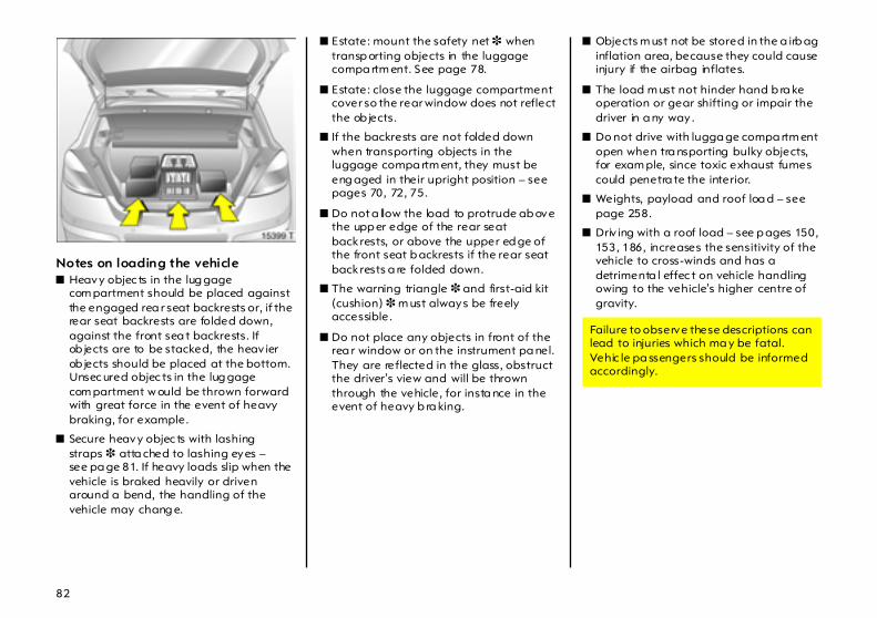
82
Notes on loading the vehiclez Heavy objec ts in the lug gage
com partment should be placed against the engaged rea r seat backrests or, if the rear seat backrests are folded down, against the front sea t backrests. If ob jects are to be stacked, the heav ier ob jects should be placed at the bottom. Unsec ured objec ts in the lug gage com partment w ould be thrown forward with great force in the event of heavy braking, for example.
z Secure heavy objec ts with lashing straps 3 atta ched to lashing eyes – see pa ge 81. If heavy loads slip when the vehicle is braked heavily or driven around a bend, the handling of the vehicle may chang e.
z Estate: mount the safety net 3 when transp orting objects in the luggage compa rtm ent. See page 78.
z Estate: close the luggage compartment cover so the rear window does not reflect the ob jects.
z If the backrests are not folded down when transporting objects in the luggage compa rtm ent, they must be eng aged in their upright position – see pages 70, 72, 75.
z Do not a llow the load to protrude ab ove the upp er edge of the rear seat back rests, or above the upper ed ge of the front seat b ackrests if the rear seat back rests a re folded down.
z The warning triangle 3 and first-aid kit (cushion) 3 m ust always be freely accessible.
z Do not place any objects in front of the rea r window or on the instrument pa nel. They are reflected in the glass, obstruct the driver’s view and will be thrown through the vehicle, for insta nce in the event of heavy b ra king.
z Objects m ust not be stored in the a irb ag inflation area, because they could cause injury if the airbag inflates.
z The load m ust not hinder hand b ra ke operation or gear shifting or impair the driver in a ny way.
z Do not drive with lugga ge compa rtm ent open when tra nsporting bulky objects, for exam ple, since toxic exhaust fumes could penetra te the interior.
z Weights, payload and roof loa d – see page 258.
z Driv ing with a roof load – see p ages 150, 153, 186, increases the sensitivity of the vehicle to cross-winds and has a detrimenta l effec t on vehicle handling owing to the vehicle’s higher centre of gravity.
Failure to observe these descriptions can lead to injuries which ma y be fatal. Vehic le pa ssengers should be informed accordingly.
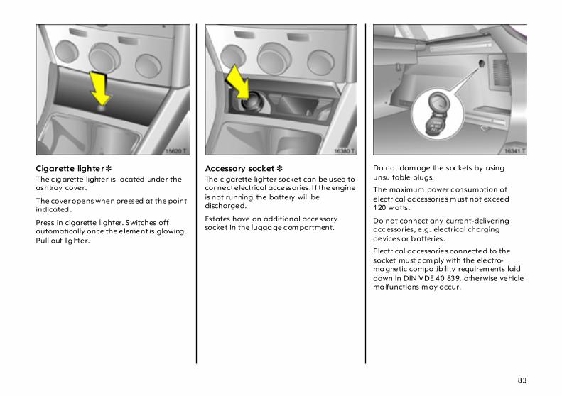
83
Cigarette lighter 3 The c ig arette lighter is located under the ashtray cover.
The cover opens when pressed at the point indicated .
Press in cigarette lighter. Switches off automatically once the element is glowing . Pull out lig hter.
Accessory socket 3 The cigarette lighter socket can be used to connect electrical accessories. I f the engine is not running the battery will be discharged.
Estates have an additional accessory socket in the lugga ge c om partment.
Do not dam age the soc kets by using unsuitable plugs.
The maximum power c onsumption of electrical ac cessories m ust not exceed 120 w atts.
Do not connect any current-delivering acc essories, e.g. electrical charging devices or b atteries.
E lectrical ac cessories connected to the socket must c om ply with the electro-ma gnetic compa tib ility requirem ents laid down in DIN VDE 40 839, otherwise vehicle ma lfunctions m ay occur.
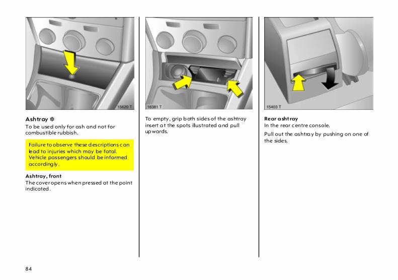
84
Ashtray 3 To be used only for ash and not for combustible rubbish.
Ashtray, front The cover opens when pressed at the point indicated .
To empty , grip b oth sides of the ashtray insert a t the spots illustrated a nd pull up wards.
Rear a shtray In the rear c entre console.
Pull out the ashtra y by pushing on one of the sides.
Failure to observe these d escriptions c an lead to injuries which may be fatal. Vehicle passengers should be informed according ly .
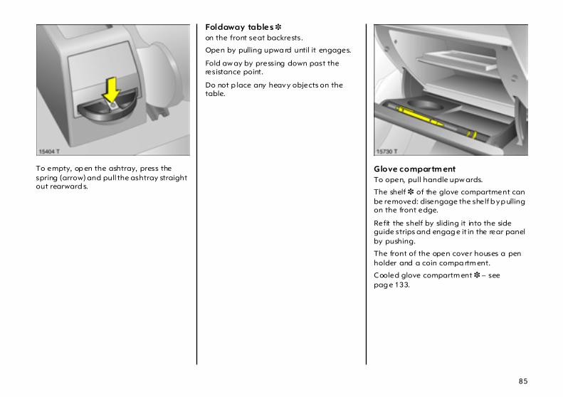
85
To empty, op en the ashtray, press the spring (arrow) and pull the ashtray straight out rearward s.
Foldaway tables 3 on the front seat backrests.
Open by pulling upwa rd until it engages.
Fold aw ay by pressing down past the resistance point.
Do not p lace any heavy objects on the table.
Glove compartm ent To open, pull handle upw ards.
The shelf 3 of the glove compartment can be removed: disengage the shelf b y p ulling on the front edge.
Refit the shelf by sliding it into the side guide strips and engag e it in the rear panel by pushing.
The front of the open cover houses a pen holder and a coin compa rtm ent.
Cooled glove compartm ent 3 – see pag e 133.
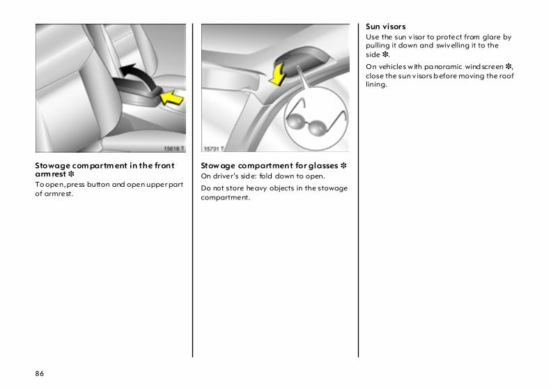
86
Stowage com partm ent in the front arm rest 3 To open, press button and open upper part of armrest.
Stow age compartment for glasses 3 On driver’s sid e: fold down to open.
Do not store heavy objects in the stowage compartment.
Sun visors Use the sun v isor to protect from glare by pulling it down and swivelling it to the side 3.
On vehicles w ith pa noramic wind screen 3, close the sun v isors b efore moving the roof lining.
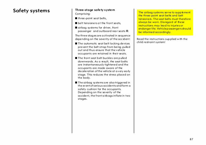
87
Safety systems Three-stage safety system Comprising:
z three-point seat belts,
z belt tensioners a t the front seats,
z airbag systems for driver, front passenger and outboard rea r seats 3.
The three stag es are a ctivated in sequence depending on the severity of the acc id ent:
z The automa tic seat belt locking devices prevent the belt strap from being pulled out and thus ensure that the vehicle occupants are retained in their seats.
z The front seat b elt buckles are p ulled downwards. As a result, the seat b elts are instantaneously tightened and the occupants are made aware of the deceleration of the vehicle at a very ea rly stage. This reduces the stress placed on the body.
z The airbag systems a re also triggered in the event of serious accidents and form a safety cushion for the occupants. Depending on the severity of the accident, the front a irb ags inflate in two stages.
Read the instructions sup plied w ith the child restraint system!
The airbag systems serve to supp lement the three-point seat belts and belt tensioners. The seat belts must therefore always be worn. Disregard of these instructions may lea d to injuries or endanger life. Vehicle p assengers should be informed accordingly.

88
Seat belts
In the event of an accident, persons not wearing seat belts endanger their fellow occupants and themselves.
Control indicator X 3 for the sea t belt – see page 27.
Seat belts are designed to be used by only one person at a time. They are not suitable for children under 12 years of age or 150 cm unless an a ppropria te child restraint system is used.
For children up to 12 yea rs of ag e, w e recom mend the Vauxhall child restraint system – see page 104.
Three-point seat belts The vehic le is equip ped with three-point seat belts with automatic retractors and lock ing dev ices, allowing freedom of b od y movem ent although the spring tensioned belts always ensure a snug fit. Correct seat position – see pag es 67, 90, 94.
The belt has a "vehicle sensitive retractor" whic h is d esigned to lock during heavy acceleration or deceleration in any direction.
Belt tensioners The front seat belt systems are equipped with belt tensioners. In the event of a head-on or rear-end collision of a certa in severity, the b elt buckles are p ulled down, thus tightening the b elts.
Actuation of belt tensioners is indicated by illumination of control indicator v , see next page.
The b elt tensioners must be repla ced a fter activa tion. We rec om mend that you consult your Vauxhall Authorised Repa irer.
If the seat belts are undama ged the operation thereof is unaffec ted, even if the belt tensioners have b een trigg ered .
Further information – see page 91.
Alwa ys wea r your seat belt, and that means also in urb an traffic and when you are a rear seat passenger. It can save your life!
Pregnant women m ust alwa ys wear a seat belt – see page 90.
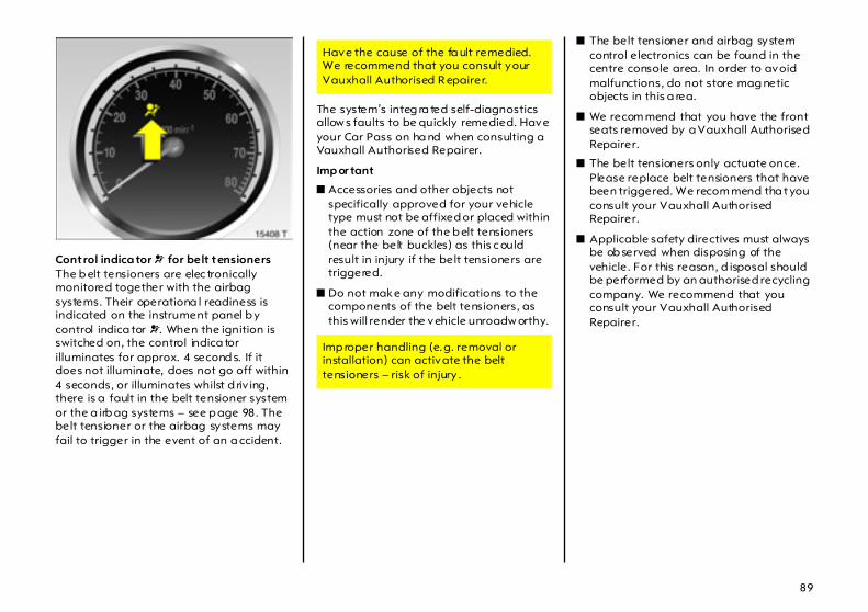
89
Control indica tor v for belt tensioners The b elt tensioners are elec tronically monitored together with the airbag systems. Their operationa l readiness is indicated on the instrument panel b y control indica tor v. When the ignition is switched on, the control indica tor illuminates for approx. 4 second s. If it does not illuminate, does not go off within 4 seconds, or illuminates whilst d riv ing, there is a fault in the belt tensioner system or the a irb ag systems – see p age 98. The belt tensioner or the airbag systems may fail to trigger in the event of an a ccident.
The system’s integ ra ted self-diagnostics allow s faults to be quickly remedied. Have your Car Pass on ha nd when consulting a Vauxhall Authorised Repairer.
Imp or tant
z Accessories and other objects not specifically approved for your vehicle type must not be affixed or placed within the action zone of the b elt tensioners (near the belt buckles) as this c ould result in injury if the belt tensioners are triggered.
z Do not make any modifications to the components of the belt tensioners, as this will render the vehicle unroadw orthy.
z The belt tensioner and airbag system control electronics can be found in the centre console area. In order to avoid malfunctions, do not store mag netic objects in this a rea.
z We recom mend that you have the front seats removed by a Vauxhall Authorised Repairer.
z The belt tensioners only actuate once. Please replace belt tensioners that have been triggered. We recom mend tha t you consult your Vauxhall Authorised Repairer.
z Applicable safety directives must always be ob served when disposing of the vehicle. For this reason, d isposal should be performed by an authorised recycling company. We recommend that you consult your Vauxhall Authorised Repairer.
Have the cause of the fa ult remedied. We recommend that you consult your Vauxhall Authorised R epairer.
Imp roper handling (e.g. removal or installation) can activate the belt tensioners – risk of injury .

90
Using the belts Fitting seat bel ts Pull the belt out of the retractor and guide it across the body, making certain that it is not twisted.
Insert the la tch plate into the buckle. The front sea t b ackrest must not be tilted back too far or the seat belt will not op erate properly . The recommended angle of inclina tion is 25° . Make sure that the lap belt is not twisted and that it fits snugly across the body. Tension the belt frequently while d riv ing by tugging the diagonal pa rt of the belt.
Bulky clothing prevents the belt from fitting prop erly. The belt must not rest against ha rd or fragile objects in the pockets of your clothing (e.g. ballpoint pens, keys, spectacles) because these could cause injury. Do not place any objec ts (e.g. ha ndb ags, mobile phones) b etween the belt and your body.
Height adjustm ent of upper anchorag e point of front and rear 3 sea t belts:
1. Pull b elt out slig htly.
2. Press d own button on adjuster slide.
3. Move adjuster slide up or down.
4. Allow sliding ad juster to a ud ib ly latch.
Do not adjust height while driving .
On pregnant women in particular, the lap belt must be positioned as low as possible ac ross the pelv is so as not to put too much pressure on the abdomen.
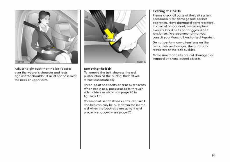
91
Adjust height such that the belt p asses over the wearer’s shoulder and rests against the shoulder. It must not pass over the neck or upper arm.
Rem oving the b el t To remove the belt, d epress the red pushbutton on the buckle; the b elt will retract automatically.
Three-point seat belts on rear outer seats When not in use, pass seat belts throug h side holders as shown on pa ge 70 in fig. 16321 T.
Three-point seat b el t on centre rear sea t The belt can only be pulled from the inertia reel when the backrests are up rig ht a nd prop erly engaged – see p age 70.
Testing the belts Plea se check all parts of the b elt system occasionally for dama ge a nd correct operation. H ave da maged parts replaced . In ca se of an accident, please replace overstretc hed belts and triggered belt tensioners. We recommend that you consult your Vauxhall Authorised Repa irer.
Do not perform any altera tions on the belts, their anchorages, the automatic retrac tors or the belt buck les.
Make sure that b elts are not da maged or trapped by sharp-edged objec ts.
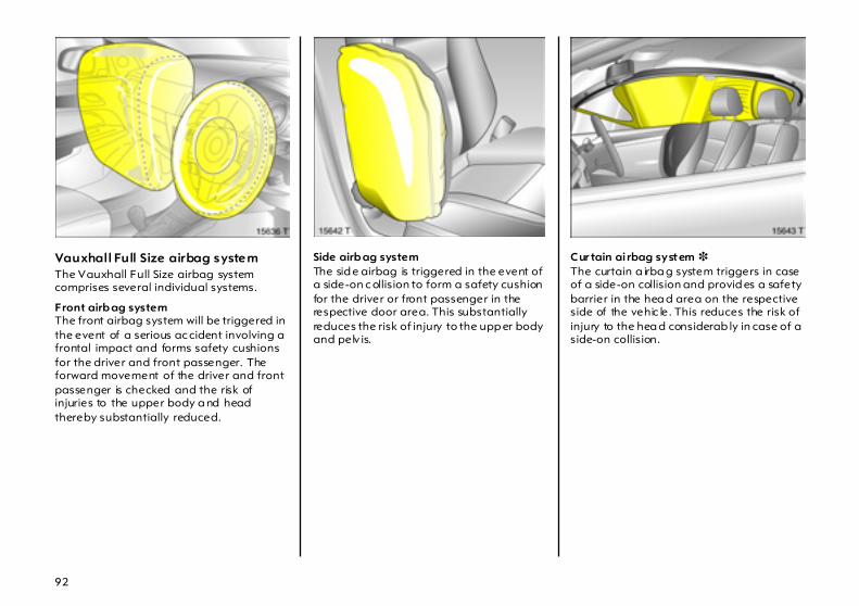
92
Vauxhall Full Size airbag system The Vauxhall Full Size airbag system comprises several individual systems.
Front airb ag system The front airbag system will be triggered in the event of a serious ac cident involving a frontal impact and forms safety cushions for the driver and front passenger. The forward movement of the driver and front passenger is checked and the risk of injuries to the upper body a nd head thereby substantially reduced.
Side airb ag system The sid e airbag is triggered in the event of a side-on c ollision to form a safety cushion for the driver or front passenger in the respective door area. This substantially reduces the risk of injury to the upp er body and pelv is.
Cur tain ai rbag system 3 The curtain a irba g system triggers in case of a side-on collision and provid es a safety barrier in the hea d area on the respective side of the vehic le. This reduces the risk of injury to the hea d considerab ly in case of a side-on collision.
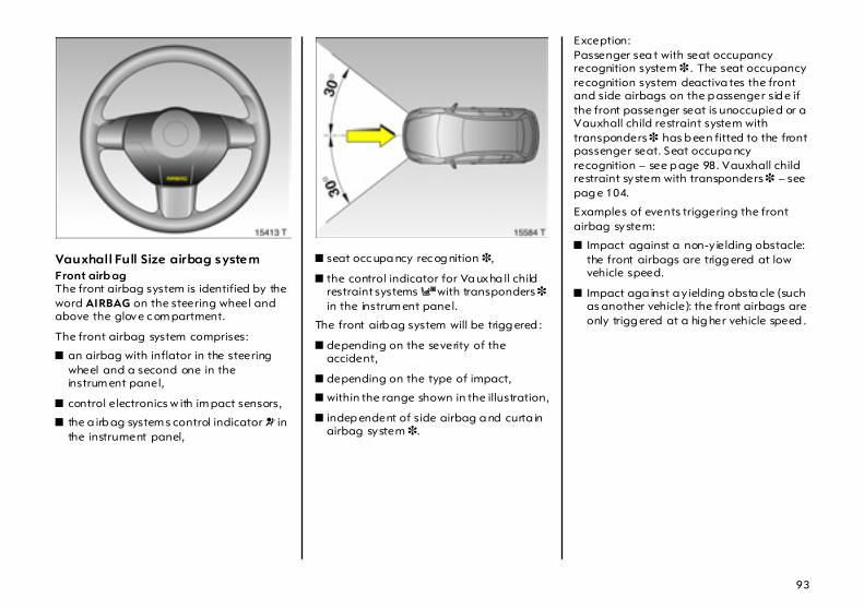
93
Vauxhall Full Size airbag system Front airb ag The front airbag system is identified by the word AIRBAG on the steering wheel and above the glove c om partment.
The front airbag system comprises:
z an airbag with inflator in the steering wheel and a second one in the instrum ent panel,
z control electronics w ith im pact sensors,
z the a irb ag system s control indicator v in the instrument panel,
z seat occ upa ncy rec og nition 3,
z the control indicator for Va uxha ll child restraint systems y with transponders 3 in the instrum ent panel.
The front airb ag system will be trigg ered :
z depending on the severity of the accident,
z depending on the type of impact,
z within the range shown in the illustration,
z indep endent of side airbag a nd curta in airbag system 3.
Exception: Passenger sea t with seat occupancy recognition system 3 . The seat occupancy recognition system deactiva tes the front and side airbags on the p assenger sid e if the front passenger seat is unoccupied or a Vauxhall child restraint system with transponders 3 has b een fitted to the front passenger seat. Seat occupa ncy recognition – see p age 98. Vauxhall child restraint system with transponders 3 – see pag e 104.
Examples of events triggering the front airbag system:
z Impact against a non-y ielding obstacle: the front airbags are trigg ered at low vehicle speed.
z Impact aga inst a y ielding obsta cle (such as another vehicle): the front airbags are only trigg ered at a hig her vehicle speed .

94
When trigg ered , the front airbags inflate in milliseconds to form a safety cushion for the d river and front passenger. The forward movement of the front seat occupants is c hecked, thereby sub stantially reducing the risk of injury to the upp er body and hea d.
No im pairment of view will occur, because the a irb ags inflate and deflate so quickly that it is often not even noticed in an accident.
The front airbag system will not be triggered in the event of
z the ignition is switched off z minor frontal collisions z accidents in which the vehicle overturns z collisions involving a sid e or rear impac t that is to say, if it w ould not be of benefit to the oc cup ants.
The front airbag system provides optimum p rotection when the seat, back rest and head restra int are correctly adjusted: Adjust the driver’s seat according to the occupant’s height such that with the driver sitting upright the steering wheel is held in the a rea of its upper sp okes with the d river’s arms slightly bent. The pa ssenger seat should be as far back as possible, with the back rest upright – see pages 5, 67. Do not place the head, body, hands or feet on the c overs of the airbag systems.
Do not place any objects in the area in which the airb ags inflate. Im portant inform ation – see page 101.
The three-point seat belt must be correctly fitted – see page 90.
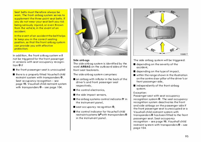
95
In add ition, the front a irb ag system w ill not be trig gered for the front passenger in versions with seat occupancy recogni-tion 3 if
z the front p assenger seat is unoccupied
z there is a prop erly fitted Va uxha ll child restraint system with transponders 3 . Seat oc cup ancy recognition – see page 98. Vauxhall child restraint system with transponders 3 – see page 104.
Side airb ags The side a irb ag system is identified by the word AIRBAG on the outb oa rd sides of the front seat backrests.
The side a irb ag system c om prises:
z an airbag with infla tor in the back of the driver’s and front passenger seat respectively ,
z the control electronics,
z the side impact sensors,
z the airbag systems control ind icator v in the instrum ent panel,
z seat occ upa ncy rec og nition 3,
z the control indicator for Va uxha ll child restraint systems y with transponders 3 in the instrum ent panel.
The side airbag system will be triggered:
z depending on the severity of the accident,
z depending on the type of im pact, z within the range shown in the illustration
on the centre d oor pillar of the driver’s or front passenger side,
z ind epend ently of the front airbag system.
Exception: Passenger sea t with seat occupancy recognition system 3 . The seat occupancy recognition system deactiva tes the front and side airbags on the p assenger sid e if the front passenger seat is unoccupied or a Vauxhall child restraint system with transponders 3 has b een fitted to the front passenger seat. Seat occupa ncy recognition – see p age 98. Vauxhall child restraint system with transponders 3 – see pag e 104.
Seat belts must therefore always be worn. The front airbag system serves to supplement the three-point seat belts. If you do not wea r your seat belt you risk being seriously injured, or even thrown from the vehic le, in the event of an accident.
In the event of an accident the belt helps to keep you in the correct seating position, so that the front airb ag system can provide you with effective protection.

96
When triggered, the side a irba g infla tes within milliseconds to form a safety cushion for the driver or front passeng er in the respective door area. This substantially red uces the risk of injury to the upper body and pelvis in the event of a side-on collision.
The side airba gs will not be triggered in the event of
z the ig nition is sw itc hed off,
z fronta l collisions,
z accidents in which the vehicle overturns,
z collisions involving a rear impac t,
z collisions involving a side imp act outside the passenger cell.
In addition, the side airbag system will not b e triggered for the front pa ssenger in versions with seat oc cup ancy recogni-tion 3 if
z the front passenger seat is unoccupied,
z there is a properly fitted Vauxhall child restraint system with transpond ers 3. Seat occupancy recognition – see page 98. Va uxha ll c hild restraint system with transp onders 3 – see p age 104.
Cur tain ai rbag 3 The curtain a irba g system is identified by the word AIRBAG on the roof pillar trim.
The curtain a irba g system com prises:
z an airbag w ith inflator in the roof frame on the driver’s and front passenger side respectively,
z the control electronics,
z the side im pact sensors,
z the airbag systems control indicator v in the instrument panel.
There must be no objects in the area in which the airb ag inflates or in the a rea between the seat backs and the vehicle body. Do not place the hands or arms on the covers of the airba g systems. Imp ortant information – see page 101.
The three-p oint seat b elt m ust always b e correctly fitted – see page 90.
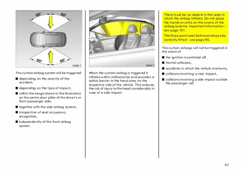
97
The curtain airbag system will be triggered:
z depending on the severity of the accident,
z depending on the typ e of impa ct,
z within the range shown in the illustration on the centre door pillar of the driver’s or front passenger side,
z together with the side airbag system,
z irrespective of seat occupancy recognition,
z independently of the front airbag system .
When the curtain airbag is triggered it inflates w ithin milliseconds and provides a safety barrier in the hea d area on the respective side of the vehicle. This reduces the risk of injury to the head considerably in case of a side impact.
The curtain airbags will not b e triggered in the event of
z the ignition is switched off,
z frontal collisions,
z accidents in which the vehicle overturns,
z collisions involving a rear impact,
z collisions involving a side impact outside the passenger cell.
There m ust be no objec ts in the area in which the airbag inflates. Do not place the hands or arms on the covers of the airbag systems. Important information – see page 101.
The three-point seat belt must always be correctly fitted – see pag e 90.
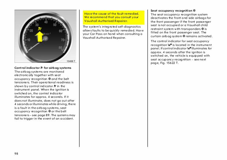
98
Control indica tor v for airb ag systemsThe a irb ag systems are monitored electronic ally together with seat occupancy recognition 3 and the belt tensioners. Their opera tional readiness is shown b y control ind icator v in the instrument panel. When the ignition is switched on, the control indica tor illuminates for approx. 4 second s. If it does not illuminate, does not go out after 4 seconds or illuminates while driving, there is a fault in the a irb ag systems, seat occupancy recognition 3 or the b elt tensioners – see page 89. The system s may fail to trigger in the event of an a ccident.
The system’s integ ra ted self-diagnostics allow s faults to be quickly remedied. Have your Car Pass on ha nd when consulting a Vauxhall Authorised Repairer.
Seat occupancy recognition 3 The seat occupancy recognition system deactivates the front a nd side airbag s for the front passenger if the front passenger seat is not occupied or a Vauxhall child restraint system w ith transponders 3 is fitted on the front passenger seat. The curtain airb ag system 3 remains activated .
The control indicator for seat occupancy recognition y is located in the instrument panel. If control indicator y illuminates for app rox . 4 seconds after the ignition is switched on, the vehicle is equip ped with seat oc cup anc y recog nition – see next pag e, Fig. 15622 T.
Have the cause of the fa ult remedied. We recommend that you consult your Vauxhall Authorised R epairer.
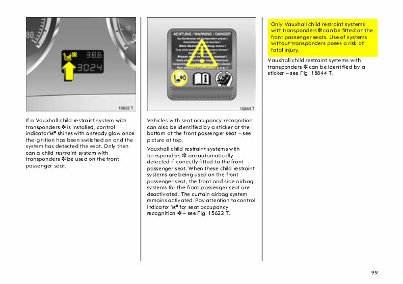
99
If a Vauxhall c hild restra int system with transponders 3 is installed , control indicator y shines with a steady glow once the ig nition has been switc hed on and the system has detected the seat. Only then can a child restraint system with transponders 3 be used on the front passenger seat.
Vehicles with seat occupancy recognition can also be id entified b y a sticker at the bottom of the front passeng er seat – see picture at top.
Vauxhall c hild restraint system s w ith tra nsponders 3 are automatically detected if correctly fitted to the front passenger seat. When these child restraint systems are b eing used on the front passenger seat, the front and side a irb ag systems for the front p assenger seat are deactivated. The curtain airbag system remains ac tivated. Pay attention to control indica tor y for seat occupancy recognition 3 – see Fig. 15622 T.
Vauxhall child restraint systems with transponders 3 can b e identified by a sticker – see Fig . 15844 T.
Only Vauxhall child restraint systems with transpond ers 3 ca n be fitted on the front passenger seats. Use of systems without transponders poses a risk of fatal injury.
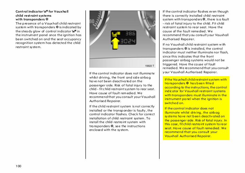
100
Control indica tor y for Vauxha llchild rest raint systems wi th transponders 3 The p resence of a Vauxhall child restraint system with tra nsponders 3 is indicated by the stea dy glow of control indicator y in the instrum ent panel once the ignition has been switched on and the seat occupancy recognition system has detected the child restraint system.
If the control indicator does not illumina te whilst driving, the front and sid e airba g ha ve not been d eactiva ted on the passenger side. Risk of fatal injury to the child - fit c hild restraint system to rear seat. Have cause of fault rem edied. We recommend that you consult your Vauxhall Authorised Repairer.
If the child restraint system is not correc tly installed or the transp onder is faulty , the control indicator flashes. Chec k for correct installation of child restraint system . To install the child restra int system with tra nsponders 3, see the instructions enclosed with the system.
If the control indicator fla shes even though there is correctly installed child restraint system with transpond ers 3 , there is a fault - risk of fatal injury to the child . Fit child restraint system to rear seat. Have the cause of the fault remedied . We recommend that you consult your Vauxhall Authorised Repa irer.
If no Vauxhall child restraint system w ith transponders 3 is installed, the control indicator must neither illuminate nor flash, since this indicates that the front passenger airbag systems would not be triggered. Have the ca use of fault remedied. We recommend that you consult your Vauxhall Authorised Repairer.
If the Va uxha ll child restraint system with tra nsponders 3 ha s b een fitted according to the instructions, the control ind ic ator for Vauxhall restraint systems with transponders must illuminate in the instrument pa nel when the ignition is switched on.
If the control indicator does not illuminate whilst driv ing , the airb ag systems ha ve not b een deactivated on the passenger side. Risk of fatal injury . In this case, fit child restra int system to rear seat. Ha ve cause of fault remedied . We recommend that you consult your Vauxhall Authorised Repairer.
101
Im portant
z Acc essories and other objects must not be affixed or placed in the a rea in which the airbags inflate a s they could cause injury if the airbags are trig gered.
z Do not p la ce a ny objects between the airb ag systems and the vehicle occ upa nts; d ang er of injury .
z Use the hooks in the roof frame only to hang up light articles of clothing or c oa t hangers. Do not place any objects in the pockets of the hanging items – risk of injury.
z The airbag system s and belt tensioner control electronics c an be found in the centre c onsole area. In ord er to avoid malfunctions, do not store magnetic ob jects in this area.
z Do not stick a nything on the steering wheel, instrument p anel, front seat backrests or roof fram e in the vicinity of the airbags, or on the front pa ssenger seat cushion, or cover any of those areas with other materials.
z Use only a dry cloth or interior cleaner to clean the steering wheel, instrum ent panel, front seat b ackrests, roof fram e and seat cushion of the front passenger seat. Do not use any a ggressive cleaning agents.
z Only protective covers whic h are approved for your Astra with side airbag system may b e fitted on the front seats. When fitting the protec tive covers, ma ke sure that the airbag units on the outboard sides of the front seat back rests a re not covered.
z The airb ag systems are triggered indep endently of each other based on the severity of the accident and the type of impac t. The side airbag system and the curtain airba g system 3 are triggered together.
z Each airbag can be trig gered only once. Onc e triggered, an airbag must be rep laced without delay. We recomm end that you consult your Vauxhall Authorised Repairer.
z The speeds, d irections of m ovement and deform ation p roperties of the vehicles, and the properties of the obstac le concerned, determine the severity of the accident and triggering of the airbags. The degree of da mage to your vehic le and the resulting repair costs alone are not indicative tha t the criteria for triggering of the airbags were m et.
z Do not perform any alterations on the components of the airbag system, as this would render the vehicle unroadworthy.
z We recom mend ha ving the steering wheel, the instrument panel, all panelling parts, the door sea ls, the handles and the seats removed by your Vauxhall Authorised Repairer.
z Applicable safety directives must always be ob served when disposing of the vehicle. For this reason, d isposal should be performed by an authorised recycling company. We recommend that you consult your Vauxhall Authorised Repairer.
6
The systems can b e triggered abrup tly and cause injury if they are ha nd led improperly.

102
z Persons weighing less than 35 kg should only tra vel on the rear seats. This does not ap ply to children who are travelling in c hild restra int system s w ith transponders 3.
z In vehicles with seat occupancy recognition 3, do not plac e any heavy ob jects on the front passenger seat otherw ise the airba g systems for the front p assenger sea t may be trigg ered in the event of an acc ident.
z In vehicles with seat occupancy recognition 3, to prevent m alfunctions do not use protective covers or sea t cushions on the front passenger seat.
z When using a Vauxhall child restraint system with tra nsponders 3 on the front passenger seat, in ord er to prevent malfunctions, no objects (e.g. plastic sheet, stickers or heated mats) m ay b e placed under the c hild restra int system .
Use of child restraint system s 3 on the front passeng er seat in vehicleswith a irbag system s, but without seat oc cupancy recognition 3
Versions with front passeng er airbag can be identified by the word AIRBAG over the glove compa rtm ent and the warning sticker on the side of the instrument panel, visible when the passenger door is open – see Fig. 11704 A.
Child restraint systems as well as other ob jects m ust never be carried on the lap of p assengers; risk of fa ta l injury. If carried in this way, child restraint system s with transponders 3 in vehicles with seat oc cup ancy recognition 3 could lead to front passenger airb ag systems not being triggered in the event of an accident.
No child restra int system 3 m ay be installed on front passenger seat. Danger to life.
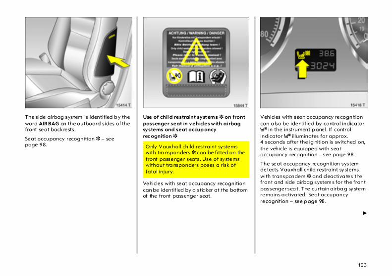
103
The side airbag system is identified b y the word AIR BAG on the outboard sides of the front seat back rests.
Seat occupancy recognition 3 – see page 98.
Use of child restraint system s 3 on front passenger seat in vehicles w ith ai rbag systems and seat occup ancy rec ognition 3
Vehicles with seat occupancy recognition can be identified by a stic ker at the bottom of the front passenger seat.
Vehicles with sea t occupancy recognition can a lso be identified by control indicator y in the instrument p anel. If control indicator y illuminates for approx. 4 seconds after the ig nition is switched on, the vehicle is equipped with seat occupancy recognition – see page 98.
The seat occupancy recognition system detects Vauxhall child restraint systems with transponders 3 and d eactiva tes the front and side airbag system s for the front passenger sea t. The curtain airba g system remains a ctivated. Seat occupancy recognition – see p age 98.
6
Only Vauxhall child restraint systems with tra nsponders 3 can be fitted on the front passenger seats. Use of systems without tra nsponders poses a risk of fatal injury.
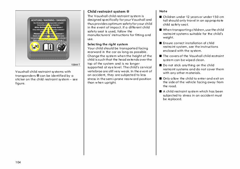
104
Vauxhall child restraint systems with transponders 3 can be identified by a stic ker on the child restraint system – see figure.
Child restraint system 3 The Vauxhall child restraint system is designed sp ecifically for your Vauxhall and thus provides optimum safety for your child in the event of impa ct. If a different child safety seat is used, follow the manufac turers’ instructions for fitting a nd use.
Selec ting the rig ht system Your child should be transported facing rearward in the car as long as possible. Change the system when the height of the child is such that the head extends over the top of the system and is no longer supported at eye level. The child’s cervical vertebrae are still very weak. In the event of an accident, they are subjected to less stress in the sem i-prone rea rw ard position than w hen upright.
Note
z Children und er 12 years or under 150 cm tall should only travel in an ap prop ria te child sa fety sea t.
z When transporting c hildren, use the child restra int system s suitable for the child’s weight.
z Ensure correct installation of c hild restra int system , see the instructions enclosed with the system.
z The covers of the Vauxhall child restraint system can b e wiped clean.
z Do not stick anything on the child restra int systems and do not cover them with any other m aterials.
z Only a llow the child to enter and exit on the side of the vehicle facing away from the road.
z A child restraint system which has been subjected to stress in an accident must be replaced.
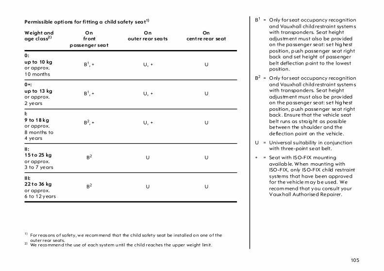
105
Permissible options for fi tting a child safety sea t1)
1) For reas ons o f safety, w e recom mend that the child safety seat be installed o n one o f the outer rear seats.
Weight and age class2)
2) We reco mmen d the use of each system u ntil the child reaches the upper weight lim it.
On fr ont
p assenger sea t
Onouter rear sea ts
Oncentre rear seat
0:up to 10 kgor approx.10 months
B1, + U, + U
0+: up to 13 kg or approx.2 years
B1, + U, + U
I: 9 to 18 kgor approx.8 months to 4 years
B2, + U, + U
II : 15 to 25 kgor approx.3 to 7 years
B2 U U
II I: 22 to 36 kgor approx.6 to 12 years
B2 U U
B1 = Only for seat occupancy recognition and Vauxhall child restraint system s with transponders. Seat height adjustm ent must also be prov ided on the pa ssenger seat: set hig hest position, p ush passenger seat right back and set height of passenger belt deflection p oint to the lowest position.
B2 = Only for seat occupancy recognition and Vauxhall child restraint system s with transponders. Seat height adjustm ent must also be prov ided on the pa ssenger seat: set hig hest position, p ush passenger seat right back . Ensure that the vehicle seat belt runs as stra ig ht as possible between the shoulder and the deflection point on the vehicle.
U = Universal suitability in conjunction with three-point seat belt.
+ = Seat with ISO-FIX mounting availab le. When mounting with ISO-FIX, only ISO-FIX child restraint systems that have been approved for the vehicle m ay b e used. We recom mend that you consult your Vauxhall Authorised Repairer.
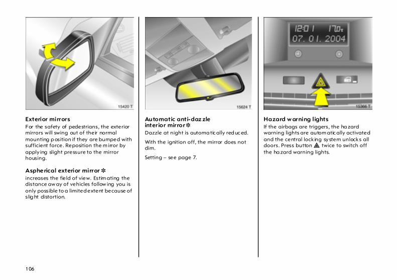
106
Exterior mirrors For the safety of pedestrians, the exterior mirrors will swing out of their normal mounting p osition if they are bumped with sufficient force. Reposition the m irror by apply ing slight pressure to the mirror housing.
Aspherical exterior mirror 3 increases the fie ld of view. Estim ating the distance aw ay of vehicles follow ing you is only possible to a limited extent because of slig ht distortion.
Automatic anti-daz zle interior mirror 3 Dazzle at night is automa tic ally red uc ed.
With the ignition off, the mirror does not dim.
Setting – see page 7.
Hazard w arning lights If the airbags are triggers, the ha zard warning lights are autom atic ally activated and the central lock ing system unlocks all doors. Press button ¨ twice to switch off the ha zard warning lights.
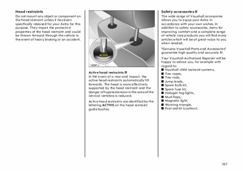
107
Head restraints Do not mount any object or component on the head restraint unless it ha s b een specifically relea sed for your Astra for this purpose. They impa ir the protective properties of the head restraint and could be thrown forward through the vehicle in the event of heavy braking or an accident.
Active head restra ints 3 In the event of a rear-end impact, the active head restraints automatically tilt forwards. The head is more effectively supported by the head restraint and the danger of hyperextension in the area of the cervical vertebra is reduced.
Ac tive hea d restra ints are identified by the lettering ACTIVE on the head restra int guid e bushes.
Safety accessories 3 The wide ra nge of Vauxhall accessories allows you to equip your Astra in acc orda nce with your own wishes. In add ition to safety accessories, item s for improving comfort a nd a complete ra nge of vehicle care p roducts you will find m any articles w hich w ill be of g reat va lue to you when need ed.
"Genuine Vauxhall Parts a nd Accessories" guarantee high quality a nd accurate fit.
Your Vauxhall Authorised Repa irer will be happy to advise you, for example with regard to: z Vauxhall child restra int system s, z Tow ropes, z Tow rods, z Jump leads, z Spare bulb kit, z Spare fuse kit, z Halogen fog lights, z Mud flaps, z Magnetic lig ht, z Wa rning triangle, z First-aid kit (cushion).

108
Lighting
Exterior lightsTurn light switch:
7 = Off 8 = Parking lights 9 = Dipp ed b eam, main beam
Dip ped beam , main b eam and head lig ht flash – see p age 15.
In positions 8 and 9, the tail lights a nd numb er plate lights are also on.
Control indica tor 8 – see page 28.
Versions with daytime running lights 3: Parking lights are on when the ignition is switched on and the light sw itch is set to 7 or AUTO . Dipped beam is on when the eng ine is running.
The daytime running lights switch off when the ignition is switched off.
Follow the regula tions of the country in which you are driving w hen using da ytime running lig hts and fog lights 3.
Driving ab road – see pag e 114.
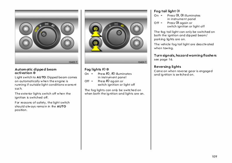
109
Autom atic dipped beam activation 3 Light switch to AU TO: Dipped beam comes on automatically w hen the engine is running if outsid e light conditions w arra nt suc h.
The exterior lights switch off w hen the ignition is switched off.
For reasons of safety, the light switch should a lw ays rema in in the AUTO position.
Fog lights > 3 On = Press > , > illuminates
in instrum ent panel Off = Press > ag ain or
switch ignition or light off
The fog lights can only be switc hed on when both the ig nition and lights are on.
Fog tail light r On = Press r, r illuminates
in instrument panelOff = Press r again or
switch ignition or light off
The fog tail light can only be switched on both the ignition and d ip ped beam /park ing lig hts are on.
The vehicle fog tail light are dea ctivated when tow ing.
Turn signals, hazard warning flashers see page 16.
Reversing lightsCom e on when reverse gear is engaged and ig nition is sw itched on.

110
Headlight range adjustm ent ? Manual hea dlight range adjustm ent 3 With dipped bea m switched on, adjust head lig ht range in four steps to suit vehicle load. Turn wheel aga inst resistanc e and click it to the req uired position.
Correct adjustment of the headlight range red uces dazzle for other road users.
Level control system 3 – see page 170.
Vehicles without level control system
z Front sea ts occupied = 0
z All seats occupied = 1
z All seats occupied andluggage compa rtm ent load = 2
z Driver’s seat occupied andluggage compa rtm ent load = 3
Vehicles with level control system
z Front sea ts occupied = 0
z All seats occupied = 1
z All seats occupied andluggage compa rtm ent load = 1
z Driver’s seat occupied andluggage compa rtm ent load = 2
Autom atic headlig ht ra nge ad justment 3 Controls headlight range on vehicles with Xenon head lig ht system .

111
Adaptive Forward Lighting 3(AFL) improves lig hting in curves (curve lighting ) on vehicles with Bi-Xenon headlight system.
Curve lig htingThe Xenon light bea m pivots based on steering wheel position a nd speed (from approx. 6 m ph or 10 km/h).
The head lig hts shine at an a ngle of up to 15° to the right or left of the direction of tra vel.
Motorwa y lig htingAt higher speeds and continuous straight forward travel, the dipp ed b eam autom atic ally shifts to a higher output, thereby increasing headlight range.
Control indic ator lig ht B Illuminated : Fault in system. The system is not rea dy for opera tion.
If the cornering light swivelling dev ice fails, the relevant dipped beam is switched off. The corresp onding fog light is automatically switched on for reasons of safety.
Consult a workshop . We recommend your Vauxhall Authorised Repairer.
If c ontrol indicator B flashes for app rox . 4 seconds after the ig nition is switched on, the headlights have been set to symm etrical d ipped beam; see "Headlights when driving abroad" on page 114.
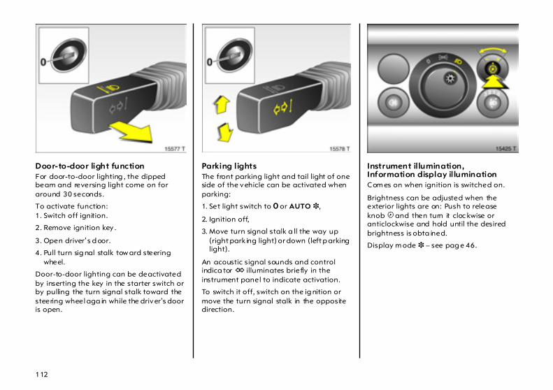
112
Door-to-door light function For door-to-door lighting , the dipped beam and reversing light come on for around 30 seconds.
To activate function: 1. Switch off ignition.
2. Remove ignition key .
3. Open driver’s d oor.
4. Pull turn sig nal stalk tow ard steering wheel.
Door-to-door lighting can be deactivated by inserting the key in the starter switch or by pulling the turn signal stalk toward the steering wheel aga in while the driver’s door is open.
Parking lights The front parking light and tail light of one side of the vehicle can be activated when parking:
1. Set light switch to 7 or AUTO 3,
2. Ignition off,
3. Move turn signal stalk a ll the way up (right park ing light) or down (left p arking light).
An acoustic signal sounds and control indica tor O illuminates briefly in the instrument panel to indicate activation.
To switch it off, switch on the ig nition or move the turn signal stalk in the opposite direction.
Instrument il lumination,Information display illumination Com es on when ignition is switched on.
Brightness can be adjusted when the exterior lights are on: Push to release knob k and then turn it cloc kwise or anticlockwise and hold until the desired brightness is obta ined.
Display m ode 3 – see pag e 46.
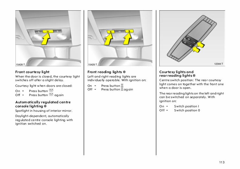
113
Front courtesy light When the door is closed, the courtesy light switches off after a slight delay.
Courtesy lig ht w hen doors are closed:
On = Press button cOff = Press button c ag ain
Autom atically regulated centre console lighting 3 Spotlight in housing of interior mirror.
Daylight-dependent, automatically reg ulated centre console lighting with ignition switched on.
Front reading lights 3 Left and right read ing lights are indiv idua lly opera ble. With ignition on:
On = Press button aOff = Press button a ag ain
Courtesy lights and rear reading lights 3 Centre switch position: The rea r courtesy light comes on together with the front one when a door is open.
The rea r reading lights on the left and right can b e switched on separately . With ignition on:
On = Switch position I Off = Switch position 0
114
Glove com partm ent lighting on when lid is open.
Illuminated mirror in the sun visors 3 The lighting switches on when the cover is opened.
Entry lighting 3 After unlocking the vehicle, the instrument and switch lighting come on for a few seconds.
Puddle light 3 After unlocking the vehicle, the number plate lights com e on for a few seconds.
Door handle lighting 3 When the exterior lights are on, the interior front door handles are illuminated .
Cigarette lighter and ashtray illumination 3 Com es on when ignition is switched on.
Luggage compartment lighting Com es on when the boot lid/tailgate is opened.
Battery discharge protection 3 To prevent the ba ttery from b ecoming discharged, the courtesy light, reading lig hts, luggag e com partment lighting and glove com partment lighting switch off autom atic ally 20 minutes after the ignition is switched off.
Light covers The inside of the lig ht c overs may mist up briefly in poor, wet and cold weather conditions, in heavy rain or after washing. The mist disappea rs q uick ly by itself; to help, switch on the lights.
Headlights when driving abroad The asymm etrical dipped b eam increases the field of v ision on the p assenger sid e of the lane.
This c auses glare for oncoming tra ffic if the vehicle is driven in countries where traffic drives on the opp osite side of the road.
Do as follows to prevent glare:
Vehicles withhalog en headl ight system or Xenon head light system 3 Have the headlights adjusted by a workshop. We recommend your Vauxhall Authorised Repa irer.
Vehicles w ith ad aptive forward lighting 3(AFL) 1. Pull a nd hold stalk for main beam on
steering wheel (hea dlight flash).
2. Switch on ignition.
3. After approx. 3 seconds, an acoustic signal sound s a nd then AFL control ind ic ator B fla shes ap prox . 4 seconds.
After the sw itc h, AFL control ind icator B flashes for 4 seconds each tim e the ignition is switched on.
To return to asym metrical d ip ped beam , pull and hold the main beam stalk again, switch on the ignition and wait for the acoustic sig nal. AFL control ind icator B will then discontinue flashing.
Control indicator B – see pag e 30.
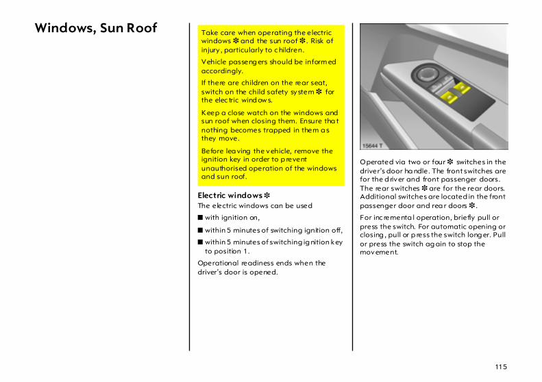
115
Windows, Sun Roof
Electric windows 3 The electric windows can be used
z with ignition on,
z within 5 minutes of switching ignition off,
z within 5 minutes of switching ig nition key to position 1.
Operational readiness ends when the driver’s door is opened.
Operated via two or four 3 switches in the driver’s door ha ndle. The front switches are for the d river and front passenger doors. The rear switches 3 are for the rear doors. Additional switches are located in the front passenger door and rea r doors 3 .
For inc rementa l operation, briefly pull or press the switch. For automatic opening or closing , pull or p ress the switch long er. Pull or press the switch ag ain to stop the movement.
Take care when operating the electric windows 3 and the sun roof 3 . Risk of injury , particularly to c hildren.
Vehicle passeng ers should be inform ed accordingly.
If there are children on the rear seat, switch on the child safety system 3 for the elec tric wind ow s.
Keep a close watch on the windows and sun roof when closing them. Ensure tha t nothing becomes trapped in them a s they move.
Before lea ving the vehicle, remove the ignition key in order to p revent unauthorised operation of the windows and sun roof.
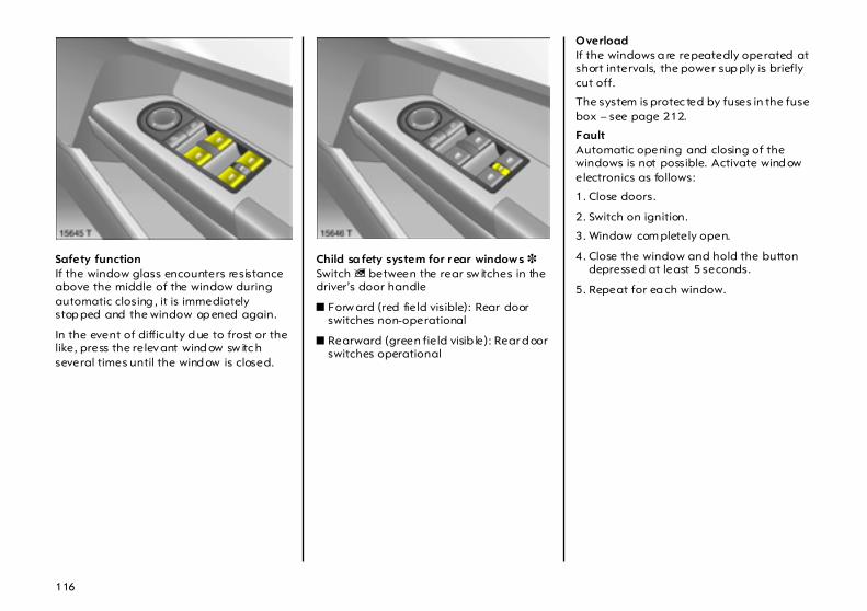
116
Safety function If the window glass encounters resistance above the middle of the window during automatic closing , it is immediately stop ped and the window op ened again.
In the event of difficulty d ue to frost or the like, press the relevant wind ow sw itc h several times until the wind ow is closed.
Child sa fety system for r ear window s 3 Switch z between the rear sw itches in the driver’s door handle
z Forw ard (red fie ld visible): Rear door switches non-operational
z Rearward (green fie ld visib le): Rear d oor switches operational
Overload If the windows a re repeatedly operated at short intervals, the power sup ply is briefly cut off.
The system is protec ted by fuses in the fuse box – see page 212.
Fault Automatic opening and closing of the windows is not possible. Activate wind ow electronics as follows:
1. Close doors.
2. Switch on ignition.
3. Window com pletely open.
4. Close the window and hold the button depressed at least 5 seconds.
5. Repeat for ea ch window.
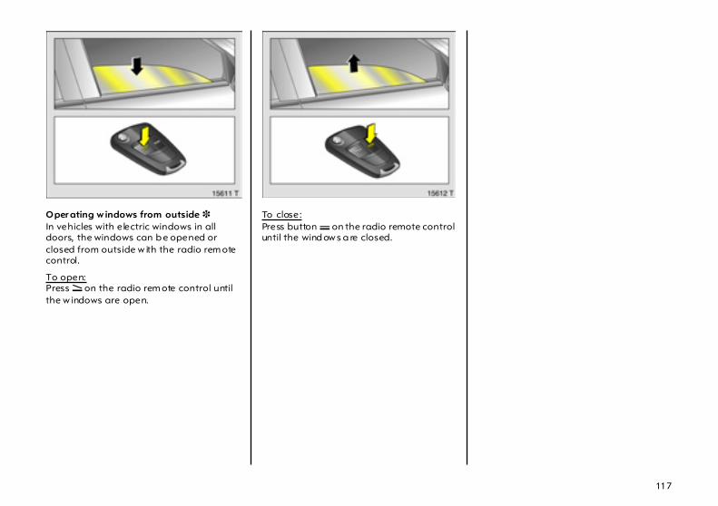
117
Oper ating w indows from outside 3 In vehicles with electric windows in all doors, the windows can b e opened or closed from outside w ith the radio rem ote control.
To open:Press q on the radio rem ote control until the w indows are open.
To close:Press button p on the radio remote control until the wind ow s a re closed.
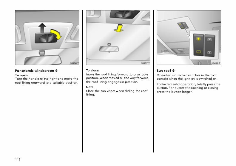
118
Panoramic windscreen 3 To open: Turn the handle to the right and move the roof lining rearward to a suitable position.
To close: Move the roof lining forward to a suitable position. When moved all the way forward, the roof lining engages in p osition.
Note Close the sun visors w hen sliding the roof lining.
Sun roof 3 Operated via roc ker switches in the roof console when the ignition is switched on.
For increm ental operation, b riefly press the button. For autom atic opening or closing , press the button longer.

119
To raise: When the roof is closed, press button ü . The roof is tilted in the rear.
To open: Press button ü again from the tilted position. The roof op ens to its stop.
To close: Press button d.For reasons of safety, the roof closes from its open position to approx. 20 cm. Hold button d depressed to close the roof completely.
Sunblind Used to reduc e sun penetra tion into the interior when the sun roof is closed.
The sunblind opens w hen the sun roof op ens.
To op en: Press button G. The sunblind opens to its stop.
To close: Press button H.
For reasons of safety, the blind closes from its open position to approx . 20 cm. H old button d depressed to close c om pletely.
Note z If the top of the roof is wet, raise roof,
allow water to run off and then open roof.
z When using a roof rack , chec k the clearance of the sun roof to avoid damage.
Overload If the system is overload ed, the power supply is automatically cut off for a short time.
The system is protec ted by fuses in the fuse box – see page 212.
Fault If the sun roof and sunblind do not opera te properly , ac tivate electronics as follows:
1. Switch on ignition.
2. Close the sun roof and hold button d depressed at least 10 seconds.
3. Close sunb lind and hold button H depressed at least 10 seconds.

120
Climate control
Heating and ventilation system with optional air conditioning system 3 Ventilation, heating and cooling 3 a re combined into one unit that is d esigned to prov ide com fort regardless of the season, weather or outside temperature.
When cooling 3 is activated, the air is cooled and dried.
The heating unit heats the air a s required in all operating m od es depending on the position of the temperature switch. The air supply can be adjusted to suit requirements by means of the fan.
Buttons for cooling n and recirculation system 4 are only present in versions with op tional a ir conditioning system 3 – see p age 122.
Electronic climate control system 3 The electronic air conditioning system provides maxim um comfort under any weather conditions, at any outside temperature and at a ll tim es of the year.
To ensure a constant and com fortable climate in the vehicle, the temperature of the inflowing air, the air-flow rate and the air distribution are changed a utomatically acc ording to clim atic conditions outside the vehicle.
Settings are shown on the inform ation display.
E lectronic climate control system – see pag e 127.
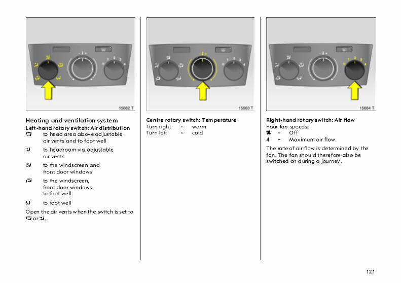
121
Heating and ventilation system Left -hand rota ry switch: Air d istribution L to head area ab ove ad justable
air vents and to foot well
M to headroom via adjustableair vents
l to the windscreen andfront door windows
J to the windscreen,front door windows,to foot well
K to foot well
Open the air vents w hen the switch is set to L or M.
Centre rotary switch: Tem perature Turn right = warmTurn left = cold
Rig ht-hand rotary swi tch: Air flow Four fan speeds: x = Off 4 = Maximum air flow
The ra te of air flow is determined by the fan. The fan should therefore also be switched on d uring a journey .
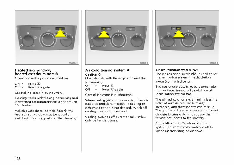
122
Heated rear window,heated exterior mirrors 3 Operation with ignition switched on:
On = Press ÜOff = Press Ü again
Control indicator in pushbutton.
Heating works with the engine running and is sw itched off automatically a fter around 15 minutes.
Vehicles with diesel particle filter 3: the heated rear window is automatically switched on during particle filter cleaning.
Air conditioning system 3 Cooling n Operate only with the engine on and the fa n running: On = Press n Off = Press n again
Control indica tor in p ushbutton.
When cooling (AC compressor) is active, air is cooled and dehumidified. If cooling or dehumidification is not desired, switch off cooling in order to save fuel.
Cooling switches off automatically at low outside temperatures.
Air rec irculation system 4 The recirculation switch 4 is used to set the ventilation system in recirc ulation mode (control indica tor).
If fumes or unpleasa nt od ours penetrate from outside: temporarily switch on air recirc ulation system 4 .
The air recirculation system minimises the entry of outside air. The humidity increa ses, and the w indows can mist up. The quality of the pa ssenger com partment air d eteriorates w hich m ay ca use the vehicle occupants to feel drowsy.
Air distribution to l: air rec irculation system is a utomatically switched off to speed up d emisting of windows.
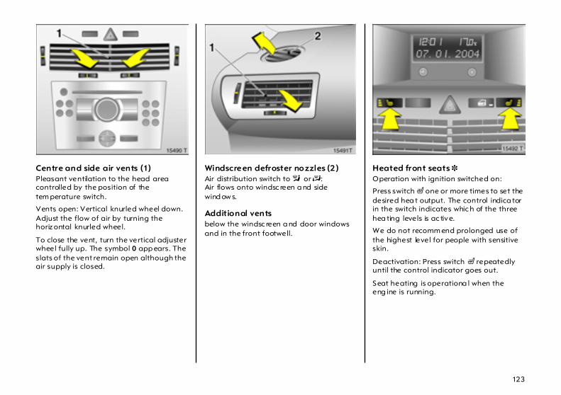
123
Centre and side air vents (1) Pleasant ventilation to the head area controlled by the position of the tem perature switch.
Vents open: Vertical knurled wheel down. Adjust the flow of air by turning the horiz ontal knurled wheel.
To close the vent, turn the vertical adjuster wheel fully up. The symbol 0 app ears. The slats of the vent remain open although the air supply is closed.
Windscreen defroster nozzles (2 ) Air distribution switch to l or J:Air flows onto windsc reen a nd side wind ow s.
Additional vents below the windsc reen a nd door windows and in the front footwell.
Heated front seats 3 Operation with ignition switched on:
Press switch ß one or more times to set the desired hea t output. The control indica tor in the switch indicates whic h of the three hea ting levels is ac tive.
We do not recomm end prolonged use of the highest level for people with sensitive skin.
Deactivation: Press switch ß repeatedly until the control indicator goes out.
Seat heating is operationa l when the eng ine is running.
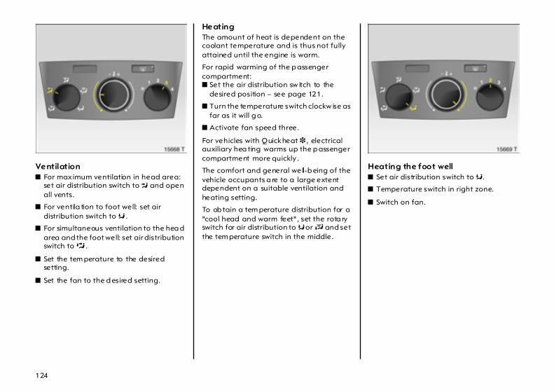
124
Ventilation z For maximum ventilation in head area:
set air distribution switch to M and open all vents.
z For ventila tion to foot well: set air distribution switch to K .
z For simultaneous ventilation to the hea d area and the foot well: set air distribution switch to L .
z Set the tem perature to the desired setting.
z Set the fan to the d esired setting.
Heating The amount of heat is dependent on the coolant temperature and is thus not fully attained until the engine is warm.
For rapid warming of the p assenger compartment: z Set the air distribution sw itch to the
desired position – see page 121.
z Turn the temperature switch clockw ise as far as it will g o.
z Activate fan speed three.
For vehicles with Quickheat 3 , electrical auxiliary hea ting warms up the p assenger compartment more quickly .
The comfort and general well-b eing of the vehicle occupants a re to a large extent dependent on a suitable ventilation and heating setting.
To ob tain a tem perature distribution for a "cool head and warm feet" , set the rota ry switch for air distribution to K or J and set the tem perature switch in the middle.
Heating the foot well z Set air distribution switch to K.
z Temperature switch in right zone.
z Switch on fan.
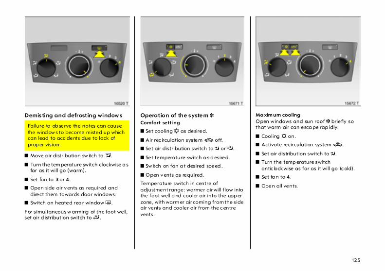
125
Demisting and defrosting window s
z Move a ir distribution sw itch to l.
z Turn the tem perature switch clockwise a s far as it will go (warm).
z Set fan to 3 or 4.
z Open side air vents as required and direct them towards door windows.
z Switch on heated rea r window Ü .
For simultaneous w arming of the foot well, set air d istribution switch to J .
Operation of the system 3 Comfort sett ing
z Set cooling n as desired.
z Air rec irculation system 4 off.
z Set air distribution switch to M or L.
z Set temperature switch a s d esired.
z Sw itch on fan a t desired speed .
z Open vents as required.
Temperature switch in centre of adjustment range: warmer air will flow into the foot well a nd cooler air into the upp er zone, with warm er air coming from the side air vents and cooler air from the c entre vents.
Ma xim um cooling Open w indows and sun roof 3 briefly so that warm air can esca pe rap idly.
z Cooling n on.
z Activate recirculation system 4 .
z Set air distribution switch to M.
z Turn the temp erature switch antic lockwise as far as it will go (c old).
z Set fa n to 4.
z Open all vents.
Failure to ob serve the notes can cause the wind ow s to become misted up which can lead to accidents due to lack of prop er vision.
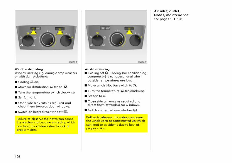
126
Window dem isting Wind ow m isting e.g. during d amp wea ther or with dam p clothing:
z Cooling n on.
z Move a ir distribution sw itch to l.
z Turn the temperature switch clockwise.
z Set fan to 4.
z Open side air vents as required and direct them towards door windows.
z Switch on heated rea r window Ü .
Wind ow de-icing z Cooling off n. Cooling (a ir cond itioning
compressor) is not operationa l when outside temperatures are low.
z Move air distribution switch to l.
z Turn the temperature sw itch c lockwise.
z Set fan to 4.
z Open side air vents as required and direct them towa rd s d oor w indows.
z Sw itch on heated rear window Ü .
Air inlet, outlet,Notes, maintenance see pages 134, 135.
Failure to ob serve the notes can cause the wind ow s to become misted up which can lead to accidents due to lack of prop er vision.
Failure to observe the notes c an cause the windows to become misted up which can lead to ac cidents due to la ck of proper vision.

127
Electronic climate control system 3 The system provides m aximum com fort in any w eather, at any outside temperature and during any season.
To ensure a constant and com fortable climate in the vehicle, the tempera ture of the inflowing air, the air-flow rate a nd the air distrib ution are cha nged automatically according to clim atic conditions outside the vehicle.
Tem perature cha ng es due to externa l influences, such as direct sunlig ht, are automatically compensated.
Data is show n on the informa tion display . Setting modifications are briefly shown in the information display, superim posing over the currently displayed menu.
The display can vary ac cord ing to the type of presentation – see p age 34.
When the ra dio remote control is used to lock the vehicle, clima te control system settings are stored for that remote control – see pa ge 56.
Manua l settings e.g. operating without cooling and a ir distrib ution c an be selected using the menu – see p age 129.
When cooling (air conditioning compressor) is active, a ir is cooled and dehumidified.
The pollen filter removes d ust, soot, pollen and spores from the inflowing outside air.
The autom atic air rec irculation system 3 has an air quality sensor 3 to detect harmful a mbient gases, in which case it will switch automatically to recirculation.
When set to automa tic mode, the c lim ate control system provides the optimal settings for almost all conditions. If nec essary , climate control system settings can b e m od ified manually.
The climate control system is only operational w hen the engine is running.
Cooling (air conditioning compressor) switches off autom atically at low outside temperatures.

128
Autom atic m ode Basic setting for max imum comfort:
z Press AUTO button.
z Open all air vents.
z Air conditioning compressor activation – see pa ge 130.
z Set pre-selected temperature to 22 °C using left rotary knob.
The temperature c an be set higher or lower as desired.
Switching off the AC compressor (Eco appea rs in display) can reduce comfort and affect safety – see pa ge 130.
All air vents are actuated autom atically in autom atic mode. The a ir vents should therefore always be open – see page 123.
Autom atic air recirculation mod e 3 The ventilation system is set to recirculation mode and interior a ir is recirculated.
The automatic air recircula tion system has an air qua lity sensor to d etect harmful gases in the outside air, in whic h case it will switch automatically to recirculation.
If outside temperatures are low and cooling (air conditioning c om pressor) is switched off, automa tic air recirculation is only available in a limited cap acity so as to prevent the windows from misting. Activate recirc ulation ma nually if so d esired.
Switc hing automatic recirc ulation on or off – see page 132.
Manual recirculation mode – see page 132.

129
Temperature The left rotary knob ca n be used to set tem peratures between 16 °C and 28 °C.
For reasons of comfort, tempera ture can only be changed in sm all increments.
For vehicles w ith Quickheat 3, e lectrical heating w arms up the pa ssenger compartment more quickly.
If a temperature below 16 °C is set, Lo appears in the display: the climate control system runs constantly at maximum cooling power. The tempera ture is not reg ulated.
If a temperature ab ove 28 °C is set, Hi appears in the display: the climate control system runs constantly at maximum heating p ow er. The temp erature is not reg ulated.
Tem perature settings are stored when the ignition is switched off.
Manual settings Und er certain circumstances (e.g. iced or misted windows), the functions of the climate control system can be modified manually.
Climate control system settings can be cha ng ed v ia the centre knob, the buttons and the m enus depicted on the d isplay .
Press the centre knob to call up the menu. The menu for m anual climate control system settings appears in the disp lay.
Individ ual menu item s are m arked by turning the centre knob and selected by pressing it. Selecting certain menus by pressing the knob will open a subm enu 3.
To ex it a menu, turn the c entre knob left or right to Return or Ma in and select.
Manual settings are stored when the ignition is switched off.
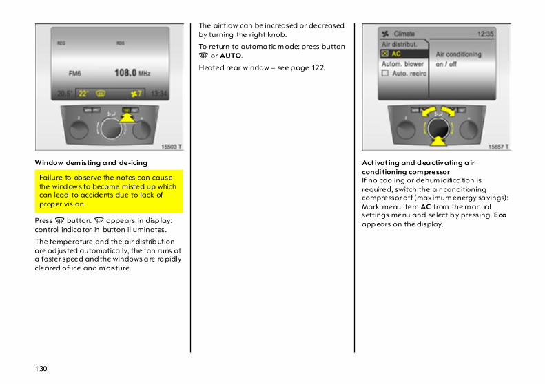
130
Window dem isting a nd de-icing
Press V button. V appears in disp lay: control indica tor in button illuminates.
The temperature and the air distrib ution are ad justed automatically, the fan runs at a faster speed and the windows a re ra pidly cleared of ice and m oisture.
The air flow can be increased or decreased by turning the right knob.
To return to automa tic m ode: press button V or AUTO.
Heated rear window – see p age 122.
Act ivat ing and d ea ctivating a ir condi tioning com pressor If no cooling or dehum idifica tion is required, switch the air conditioning compressor off (max imum energy sa vings): Mark menu item AC from the m anual settings menu and select b y pressing. Eco app ears on the display.
Failure to ob serve the notes can cause the wind ow s to become misted up which can lead to accidents due to lack of prop er vision.
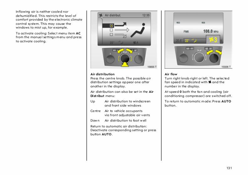
131
Inflowing air is neither cooled nor dehumid ified. This restricts the level of comfort provided by the electronic climate control system. This may cause the windows to mist up, for example.
To activate cooling: Selec t menu item AC from the manua l setting s m enu and press to activate cooling.
Air distribution Press the centre knob. The possible a ir distribution settings ap pear one after another in the display.
Air distribution can also be set in the Air Dist ribut menu:
Up Air distribution to windscreenand front side windows
Centre Air to vehicle occupantsvia front adjustable air vents
Dow n Air distribution to foot w ell
Return to automatic air distribution: Deactivate corresponding setting or press button AUTO .
Air flow Turn right knob right or left. The selec ted fan speed in indicated with x and the number in the display.
At speed 0 both the fa n and cooling (air conditioning compressor) are switched off.
To return to automatic m od e: Press AUTO button.
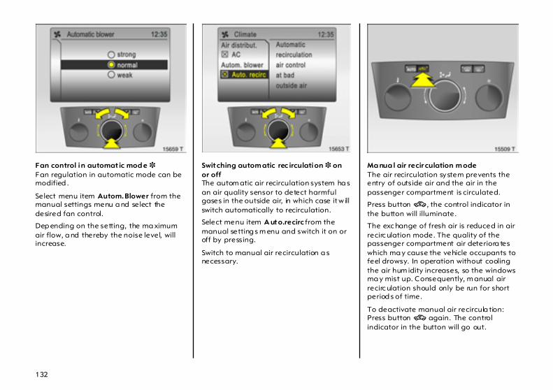
132
Fan control in automat ic mod e 3 Fan regulation in automatic mode can be modified .
Select menu item Autom.Blower from the manual settings menu a nd select the desired fan control.
Dep ending on the setting, the ma ximum air flow, a nd thereby the noise level, will increase.
Switching autom atic rec irculation 3 on or offThe autom atic air recirculation system ha s an air quality sensor to detect harmful gases in the outside air, in which case it w ill switch automatically to recirculation.
Select menu item A uto.recirc from the manual setting s m enu and switch it on or off by pressing.
Switch to manual air recirculation a s necessary.
Ma nua l air recir culation m ode The air recirculation system prevents the entry of outside air and the air in the passenger compartment is circulated.
Press button 4 , the control indicator in the button will illuminate.
The exc hange of fresh air is reduced in air recirc ulation mode. The quality of the passenger compartment air deteriora tes which ma y cause the vehicle occupants to feel drowsy. In operation without cooling the air hum idity increases, so the windows ma y mist up. Consequently, m anual air recirc ulation should only be run for short period s of time.
To deactivate manual air recircula tion: Press button 4 again. The control indicator in the button will go out.

133
Air conditioning with the engine not runningWhen the vehicle is stopped and the ignition off, the heat or cooling p ower still in the system can be used to cond ition the passenger com partment, for exam ple when stopped at a level crossing.
Press button AUTO with the ignition off. Resid ua l air c onditioning on will appear briefly in the disp lay.
The air conditioning will operate for a lim ited p eriod of time.
To cancel a ir conditioning, press the AUTO button.
Cooled glove compartm ent 3 Cooled air is fed into the glove compa rtm ent through a nozzle.
If g love com partment cooling is not required, slide the vent forw ard.

134
Air intake The air inta kes in front of the windsc reen in the engine com partment must be kept clear to allow air intake. Remove any lea ves, d irt or snow.
Air outletWhen loa ding objects in the lugga ge compartment, be careful not to cover the air inta kes in the right a nd left of the rear wall.
Pollen filter The pollen filter cleans dust, soot, pollen and spores from the air entering from outside. The active carbon layer 3 e limina tes most odours and harmful am bient gases from the air.
Replace the pollen filter at the intervals given in the Service Booklet.
135
Note If the windscreen m ists up in damp weather, set the system p rov isionally as described under "Window demisting"; see page 125, 126 or 130.
Cooling 3 functions most effic iently when the w indows and sun roof 3 are closed. I f the p assenger compartment has heated up consid erably after a long period in direc t sunlight, briefly open the windows and sun roof 3 so that the hot air can escape quickly .
When cooling 3 (air c onditioning compressor) is switched on condensation forms, which is expelled from the underside of the vehicle.
At lea st one air vent must b e open while cooling 3 (air conditioning compressor) is on in order to prevent the evaporator from icing up due to lack of air movement.
Maintenance In order to ensure continuously efficient performance, the air conditioning compressor 3 must be operated for a few minutes once a m onth, irrespective of the weather and time of year. The c lim ate control system, if present, ha ndles this autom atic ally while driving. Air conditioning compressor operation is not possible when outside tem peratures are low .
If a fault occurs, consult a w orkshop. We recommend your Vauxhall Authorised Repairer.
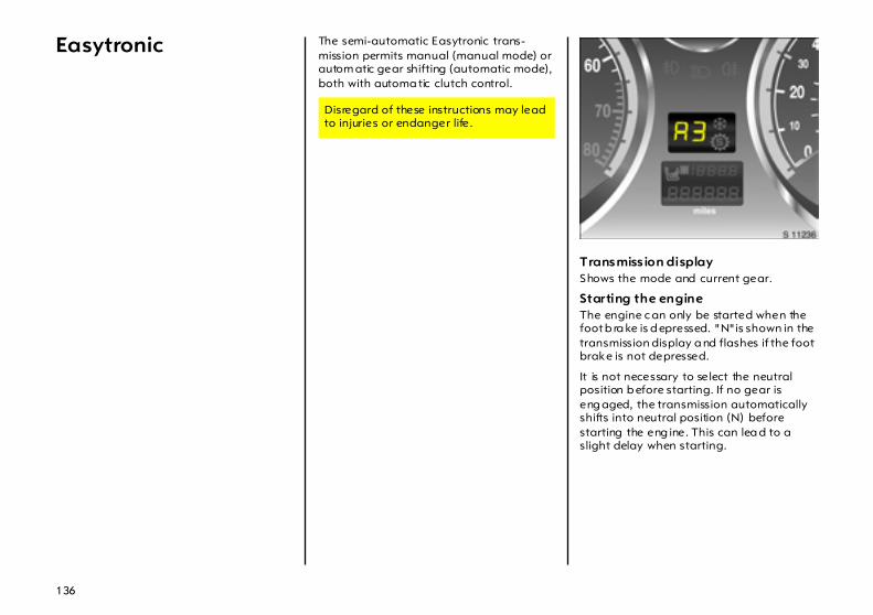
136
Easytronic The semi-automatic Easytronic trans-mission permits manual (manual mode) or autom atic gear shifting (automatic mode), both with automa tic clutch control.
Transmiss ion displayShows the mode and current gear.
Starting the engineThe engine c an only be started when the foot b ra ke is d epressed. "N" is shown in the transmission display a nd flashes if the foot brake is not depressed.
It is not necessary to select the neutral position b efore starting. If no gear is eng aged, the transmission automatically shifts into neutral position (N) before starting the eng ine. This can lea d to a slight delay when starting.
Disregard of these instructions may lead to injuries or endanger life.
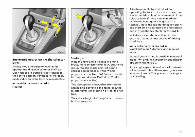
137
Easytronic operation via the selector leverAlways move the selector lever in the appropriate direction as far as it will g o. Upon release, it autom atically returns to the c entre p osition. Pay heed to the gear/mode indica tor in the transmission d isplay .
Move selector lever tow ard NNeutra l.
Start ing offPress the foot b ra ke, release the hand brake, move selector lever to A. Easytronic is in automatic mode and first gear is engaged (second gear if the Winter prog ra mme is active). "A1" appears in the tra nsmission display ("A2" if the Winter prog ra mme is active).
This also applies w hen, after starting the engine a nd activating the footbrake, the selector lever is moved to + or - for the first tim e.
The vehicle begins to "c reep " w hen the foot brake is released.
It is also possible to start off w ithout operating the foot b rake if the accelerator is operated direc tly after movement of the selector lever. If there is no immediate acc eleration, no gear is enga ged ("A" flashes). Move the selector lever toward N and start off by depressing the foot brake and m oving the selector lever toward A.
In Automatic m od e, selection of other gears is a utoma tic irrespective of driving conditions.
Move selector lever toward ASwitc h between Automatic and Manua l mode.
Manual gear shifting is possible in manual mode. "M" and the currently engaged g ear app ear in the disp la y.
If the engine speed is too low the Easytronic will autom atically shift to a lower gear even in Manual m od e. This prevents the eng ine from stalling .

138
Move selector lever tow ard + or -+ Shift to a higher gear.
- Shift to a lower gear.
If a higher gear is selected when the running speed is too low, or a lower g ear when the speed is too hig h, no shift is effected. This prevents the engine from running at too low or too high revs.
Gears ca n be skipp ed b y moving the selector lever repea tedly at short intervals.
If the vehicle is in automatic m ode, on movem ent of the selector lever to + or - Easytronic shifts to manual mode and cha ng es up or down. The transmission display shows "M" and the currently selected gear.
Move selector lever towa rd RReverse gear. Eng age only when vehicle is stationary.
Press the foot b ra ke, release the hand brake, move selector lever to R. R everse gear is engaged . "R" appears in the tra nsmission display.
The vehicle begins to "c reep " w hen the foot brake is released.
It is also p ossible to start off in reverse without operating the foot brake if the accelerator is op erated directly after movem ent of the selector lever. If there is no im med ia te acc elera tion, no gear is engaged ("R" flashes). M ove the selec tor lever toward N and start off by depressing the foot brake and mov ing the selector lever toward R.
Electronically controlled driving programm esz By m eans of delayed gear cha nging
(higher engine speed s) following a cold start, the opera ting temperature programme in automatic mode quickly and automatically brings the catalytic converter to the tem perature required for optim um polluta nt reduction.
z Adaptive programmes autom atically adapt gear shifting in automatic mode to suit the driving conditions, such as if the vehicle is towing a caravan/trailer, ha s a high pa yload, or is being driven on inclines.
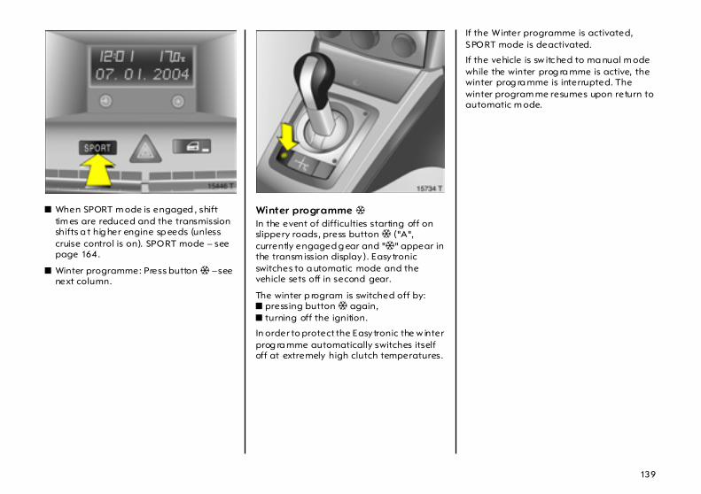
139
z When SPORT m ode is engaged , shift tim es are reduced and the transmission shifts a t hig her engine sp eeds (unless cruise control is on). SPORT mode – see page 164.
z Winter programme: Press button T – see next column.
Winter programme T In the event of difficulties starting off on slippery roads, press button T ("A", currently engaged g ear and "T" appear in the transm ission display). Easytronic switches to a utomatic mode and the vehicle sets off in second gear.
The winter p rogram is switched off by: z pressing button T again, z turning off the ignition.
In order to protect the Easytronic the w inter prog ra mme automatically switches itself off at extremely high clutch temperatures.
If the Winter programme is activated, SPORT mode is deactivated.
If the vehicle is sw itc hed to ma nual m ode while the winter prog ra mme is active, the winter prog ra mme is interrupted. The winter program me resumes upon return to automatic m ode.

140
Kickdown Accelerator pedal pressed past the pressure point: below certa in speeds, the transm ission shifts down into a lower gear. Full engine power is availab le for acceleration.
During kickdown no ma nual gea r shifting is possible.
When the engine speed approaches its up per limit, the transm ission shifts to a higher gea r during kickdown even in Manua l mode.
Without kickdown this automatic shift is not effected in Manual mode.
If SPORT mode is engaged, the drive wheels m ay spin slig htly when starting off with kickdown. This allows for maximum acceleration of the vehic le.
Engine braking assistance from motor Automat ic mod e:When driving downhill, Easytronic does not shift into higher gears until a fairly high engine speed has been reached . When braking, Easytronic shifts d ow n in good tim e.
Manual m ode:To utilise the engine braking effect, select a low er gear in good time when driv ing downhill.
Stopping the vehicle In Automatic or Ma nual m ode, when the vehicle has stopped first gear (with Winter mode eng aged, second gear) is engaged automatically and the clutch released. In R reverse remains engag ed.
When the engine is running, if the driver’s door is opened when the handbra ke is not app lied a warning tone sounds; m ove the selector lever to N and apply the handbrake.
When stopping on gradients, engage the hand brake or depress the brake pedal. To prevent overheating of the clutch, do not increa se engine speed to ensure smooth idling when in gear.
The clutch is automatically closed in the event of overheating.
Switc h off engine if stopping for a leng thy period , e.g. in traffic jams or at level crossings.
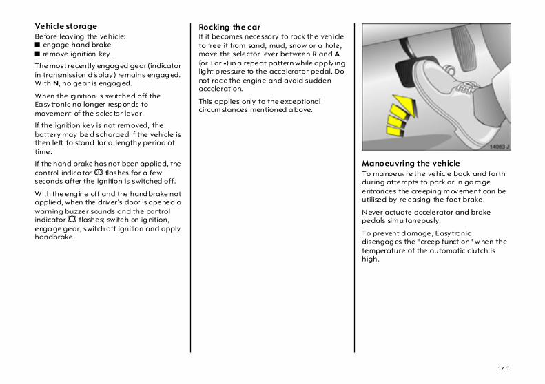
141
Vehicle storageBefore leav ing the vehicle: z engage hand brakez remove ignition key .
The most recently engag ed gear (indicator in transmission d isplay) remains engag ed. With N, no gear is engag ed.
When the ig nition is sw itched off the Ea sytronic no longer resp onds to movement of the selec tor lever.
If the ignition key is not rem oved, the battery may be d ischarged if the vehicle is then left to stand for a lengthy period of time.
If the hand brake has not been applied, the control indica tor R flashes for a few seconds after the ignition is switched off.
With the eng ine off and the hand brake not applied, when the driver’s door is opened a warning buzzer sounds and the control indicator R flashes; sw itc h on ig nition, enga ge gear, switch off ignition and apply handbrake.
Rocking the car If it becomes necessary to rock the vehicle to free it from sand, mud, snow or a hole, move the selector lever between R and A (or + or -) in a repeat pattern while app ly ing lig ht p ressure to the accelerator pedal. Do not rac e the engine and avoid sudden acceleration.
This applies only to the exceptional circum stances mentioned a bove.
Manoeuvring the vehicle To ma noeuvre the vehicle back and forth during attempts to park or in ga ra ge entrances the creeping m ovement can be utilised by releasing the foot brake.
Never actuate accelerator and brake pedals sim ultaneously.
To prevent d amage, Easytronic disengag es the "creep function" w hen the temperature of the automatic c lutch is high.

142
Fault Control indicator A illuminates in the event of a fault in the Easytronic system . In the event of serious faults, $ also a ppears in the transmission display.
It is possible to continue driving if only control indica tor A illuminates. Ma nual mode can then no longer be selected.
If $ appears in the transmission d isplay , continued driving is not possible.
Have the ca use of the fault rem edied. We recommend that you consult your Vauxhall Authorised Repairer. The system’s integrated self-diag nostics a llows faults to be q uick ly remedied.
Interruption of power supply The clutch is not disengaged if the vehicle battery is d ischarged and a gea r has been selected. The vehicle c annot m ove.
If the battery is fla t, sta rt the vehicle using jump leads – see pa ge 196.

143
If the c ause of the interruption to the p ow er sup ply is not the discharged battery , consult a workshop. We rec om mend your Vauxhall Authorised Repairer. If the vehicle has to be removed from m ov ing traffic, release clutch as follows:
1. Ap ply hand brake and switch off ig nition.
2. Open bonnet.
3. C lean Easytronic around the cap (see figure) so that no dirt can get into the opening w hen the ca p is removed.
4. Rotate cap to slacken and remove by lifting upwards – see figure.
5. Turn the a djusting screw clockwise using a flat-head screwdriver (vehicle tools 3 – see page 202) until clear resistance can be felt. The clutch has now been disengaged.
Do not turn beyond the resista nce, since this can damag e the Easytronic.
6. Fit cleaned cap ag ain. The cap must be in full contact w ith the housing.
Towing the vehic le and starting the eng ine is not perm itted when the clutch has been released in this way, although the vehicle can b e m oved a short distance.
Consult a workshop immediately . We recommend your Vauxhall Authorised Repairer.

144
Automatic transmission
After sta rting the engine and before shifting into a gea r, depress the brake pedal. If the brakes are released w hen a gear is engaged , the vehicle will "creep". Never ac tuate the a ccelerator and brake pedals simultaneously .
D can almost always b e used for d riv ing.
If the accelerator peda l is depressed gently and evenly the transmission w ill shift into the fuel-saving gears at an early stage. The drive ra nge needs be changed manually only in exceptional c ases. Select 3, 2 a nd 1 only when automatic shifting up is to be avoided or if additional use is to be made of the engine braking effect.
Select D ag ain as soon as driving conditions perm it.
Transmiss ion display Indicator of the mode of selected gear position in the transmission d isplay .
P Park p osition.
R Reverse gear.
N Neutral or idling position.
D Automatic mode.
1-4 Current gear.
Disregard of these instructions may lead to injuries or endanger life.

145
Selector lever in P, R and N
The selector lever ca n only b e moved from P when the ig nition is sw itc hed on and the foot brake d epressed (selector lever lock).
To engage P or R, p ush button on selector lever.
The engine can only be started with lever in position P or N. When position N is selected, press foot brake or engage hand brake before starting.
Do not a ccelerate d uring the selection proc edure.
Drive ranges D, 3, 2, 1
Press button on selector lever to engage 3 or 1.
The gear selector position is indicated in the tra nsmission display. When in D, the current gear is also disp la yed .
P Park position. Front wheels locked . Only engag e when the vehicle is stationary and the handbrake is applied. The transmission display shows "P" .
R Reverse gear. Only engage when the vehic le is stationary. The transmission display shows "R.
N Neutra l or idle. The transm ission display shows "N" .
D Drive position for norma l driving in 1st to 4th gear.
3, 2, 1 Transmission does not shift ab ove the selected g ear.

146
Electronically controlled driving programmes z When SPORT m ode is engaged , the
transmission shifts at higher engine speeds (unless cruise control is on). Control indicator 1 illum inates in the transmission disp lay. SPORT mode – see page 164.
z Winter programme: Press button T – see next pa ge.
z Automatic neutral shift function automatically sets the transmission to N to reduc e fuel consumption, e.g. at traffic lights.
The autom atic neutral is activated when:
As soon as the brake is released and the accelerator pedal is depressed, the vehicle starts off in the usual m anner.
z By m eans of delayed gear cha nging (higher engine speed s) following a cold start, the opera ting temperature programme quickly and automatically bring s the catalytic converter to the temperature required for optimum pollutant reduction.
z The adaptive programme autom atic ally tailors gearshifting to the d riv ing cond itions, e.g. g reater loa d or gradients.
– the selec tor lever is in D, 3, 2 or 1a nd
– the foot brake is depresseda nd
– the vehicle is sta tionarya nd
– the accelerator pedal is not a ctua ted

147
Winter programm e T In the event of starting-off diffic ulties on slip pery road s p ress b utton T, which can be operated in P, R, N , D and 3 (T illuminates in transm ission display). The vehicle starts off in third gear.
The w inter program is switched off by : z pressing button T a gain, z shifting to 2 or 1 m anually , z turning off the ignition.
In order to prevent dama ge, the winter program sw itches off automatically at high transm ission oil temperatures.
Kickdown Ac celera tor pedal pressed past the pressure point: below certain speeds, the tra nsmission shifts down into a lower gear. Full engine power is a vailable for acceleration.
Engine braking In order to utilise the eng ine braking effect when driving downhill, select drive range 3, 2 or, if nec essary , 1 in good time.
The braking action is most effective in d rive range 1. If drive range 1 is selected at too high a speed, the transmission remains in second g ear until the shift point for first gear is reached, e.g. as a result of deceleration.
Rocking the car If it becomes necessary to rock the vehicle to free it from sand, m ud , snow or a hole, move the selector lever from D to R in a repeat p attern while simultaneously app ly ing light pressure to the a ccelerator pedal. Do not race the engine and avoid sudden a cceleration.
This applies only to the exceptional circumstances mentioned above.

148
Manoeuvring the vehicle To manoeuvre the vehicle back and forth during attem pts to park or in garage entrances, the vehicle’s creeping movement c an be utilised by releasing the brake pedal.
Never actuate a ccelerator and brake pedals simultaneously.
Stopping the vehicle The selector lever ca n b e left in the c hosen gear w ith the engine running.
When stopping on grad ients engage hand brake or depress brake p edal. To prevent overheating of the transmission, do not increase engine revolutions to ensure smooth idling while standing if a gea r ha s been selected.
Switch off engine if stopping for a lengthy period, e.g. in traffic jams or at level crossings.
Before leaving the vehicle, app ly hand brake, then place selector lever in position P and rem ove ignition key.
If the ignition key is not removed, the battery m ay be discharged if the vehicle is then left to stand for a lengthy period of tim e.
The ignition key can only be removed when the selector lever is in position P.
Fault Control indicator A illuminates after the ignition is switched on. If it does not go out after the start or illum inates while driving, there is a fault in the a utomatic transmission or engine elec tronics.
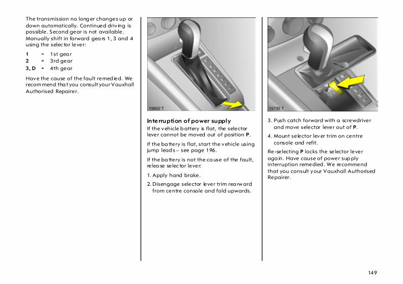
149
The transmission no long er changes up or down automatically. Continued driv ing is possible. Second gear is not available. Manually shift in forward gea rs 1, 3 and 4 using the selec tor lever:
Have the cause of the fault remed ied. We recom mend tha t you consult your Vauxhall Authorised Repairer.
Interruption of power supply If the vehicle b attery is flat, the selector lever cannot be moved out of position P.
If the ba ttery is flat, start the vehicle using jump lead s – see page 196.
If the ba ttery is not the ca use of the fault, relea se selec tor lever:
1. Apply hand brake.
2. Disengage selector lever trim rea rw ard from centre console and fold upwards.
3. Push catch forward with a screwdriver and move selector lever out of P.
4. Mount selector lever trim on centre console and refit.
Re-selecting P locks the selector lever aga in. Have cause of power sup ply interruption remedied . We recommend that you consult your Vauxhall Authorised Repairer.
1 = 1st gea r2 = 3rd gear3, D = 4th gear
150
Driving hints The first 600 m iles / 1000 km Drive your vehicle at various speed s. Do not use full throttle. Never allow the engine to labour at low revs.
Make good use of all gears. Depress the accelerator ped al a ma ximum of around three quarters of the available p edal travel in all gea rs.
Do not d rive faster than three quarters of maximum speed .
Do not b rake unnec essarily ha rd for the first 125 miles (200 km).
Never coast with engine not running Many units w ill not function in this situation (e.g. brake servo unit, e lectro-hydraulic power steering). Driving in this ma nner is a danger to yourself a nd others.
Brake servo unit When the engine is not running, the brake servo unit is no longer effective once the brake peda l has been depressed once or twice. Braking effect is not reduced , but significantly greater force is required for braking.
Electro-hydraulic power ass isted steering If the power-assisted steering fails when being towed with the engine switched off, the vehicle can still be steered, but considera bly more forc e is req uired.
Driving in mountainous terrain or with a caravan /trailerThe cooling fan is electrically operated. Its cooling power is therefore independent of the engine speed.
S ince a c onsiderab le am ount of heat is generated at high engine speeds and less at slower speeds, do not shift down when climb ing hills whilst the vehic le is still coping with the gradient in the hig her gear.
Driving with a roof load Do not exceed the perm issible roof load – see pages 186, 259. For reasons of safety, distribute the loa d evenly a nd secure it properly with reta ining straps. Adjust the tyre p ressure to the load conditions. Do not drive fa ster than 75 m ph (120 km/h). Check and retighten the straps frequently . Observe country-specific regulations.
Switching off the engine When you switch off, fans in the eng ine compa rtm ent may continue running for a time to cool the engine.
If the engine temperature is very high, e.g. after driving in mountainous terrain: allow the engine to id le for approx im ately two minutes in order to prevent heat acc um ulation.
151
Vehicles w ith turb ocharged engine After running at hig h engine speeds or high engine loa ds, operate the engine briefly at a low load or run in neutra l for approx. 30 second s before switc hing off in order to protect the turbocha rger.
Save energy – more miles Please observe the running-in hints on the previous pag e and the tips for energ y saving on the following pages.
Good, technica lly correct and economical driving ensures ma ximum durability and performance for your vehic le.
Overrun The fuel supply is autom atically shut off during overrun, e.g. when the vehicle is being driven down long gradients or when braking. To enable the overrun cut-off to take effect, do not acc elerate during overrun and, if in manual transm ission mode, do not de-clutch. To prevent dam age to the cata lytic converter, overrun cut-off is temp orarily deactivated when the catalytic converter temperature is high.
Vehicles w ith turb ocharged engine Flow -g enerated noises may be aud ible if the a ccelerator is released quickly on account of air flow in the turbocharger.
Engine speed Drive in a low engine speed range for each gear a s m uc h as possible.
Warming up After a cold start, the automatic trans-mission 3 or Easytronic 3 in automatic mode shifts into higher gears at higher rp m. This allows the catalytic converter to quic kly reach the temperature req uired for optimum pollutant reduction.
Correct gear selection Engine in neutral a nd without revving in the low er gears. Stop-and-go traffic and driving a t a speed too high for the selected gear or transmission ratio increases wear and fuel consum ption.
Change down When decreasing speed, shift down into the next lowest gear. Do not slip the clutch with a high-revving engine. This is especially important when hill climb ing.
Clutch operation Alw ays dep ress the clutch ped al hard to the floor to prevent shifting difficulties and tra nsmission dam age.
When driving do not use the pedal as a foot rest; this will ca use substantial clutch wear.
Cooling fan The cooling fan is controlled v ia a therm oswitch and therefore only runs if nec essary .
Vehicles with d iesel particle filter 3 : the cooling fan comes on automatically d uring particle filter cleaning.
PedalsDo not place any ob jects in the foot well which could slip under the ped als and inhibit the pedal travel.
To ensure the pedal travel is uninhibited, there must be no mats in the area of the pedals.
Battery care When driving slowly or when the vehicle is stationary , e.g. in slow urban traffic, stop-and-go traffic or traffic jams, turn off all unnecessary electrical load s w here possible (e.g. heated rear window, heated seats).
Declutch w hen sta rting in order to relieve the strain on the starter and the ba ttery.

152
Saving fuel,Protecting the environment
Trend-setting technologyWhen developing and manufac turing your vehic le, Vauxhall used environment-friendly and in the m ain recyc la ble materials. The production methods used to make your vehicle are likewise env ironmenta lly -compatible.
Recycling of production wastes keeps the circulation of material closed. Reduction of energy a nd water requirements a lso help s to conserve natural resources.
A highly advanced design mea ns that your vehic le can be easily disassembled at the end of its working life, and the individual materials separated for subsequent re-use.
Materia ls such as asbestos and cadmium are not used . The refrigerant in the air conditioning system 3 is CFC-free.
New painting techniques employ wa ter as a solvent.
End-of-life vehicle recovery For detailed information on Va uxha ll’ s ongoing com mitment to ac hieving an environmentally susta inab le future, including; design for recycling, take back of End-of-Life Vehicles (ELVs) and the recycling of ELVs view www.va uxha ll.co.uk/recycling for details.
Energy and environment-conscious driving z High noise levels and exhaust em issions
are often a result of driving w ithout due attention to saving energy and protecting the environment.
z You should therefore drive with energy in mind – "more miles with less fuel" .
Reduce the noise level and exhaust emissions b y adopting an environment-consc ious driving style. This is extremely worthwhile and im proves the quality of life.
Fuel consum ption d epend s to a great extent on your own personal d riv ing style. The following hints are intended to help you consume fuel at a rate that is as close as possible to the specified levels – see page 255.
Check your vehicle’s fuel consumption every time you refuel. This facilitates early detection of any irregula rities causing increased fuel consumption.
Warming up z Full throttle and w arming up at idle
speed increase w ear, fuel consumption, exhaust em ission, the am ount of pollutant in the exhaust and the am ount of noise.
z Drive off as soon as possible a fter starting.
Uniform speed z Hectic driving significantly increases fuel
consumption, the exhaust emissions, the proportion of pollutant in the exhaust gas and the noise level.
z Do not accelerate a nd brake unnecessarily . Drive at uniform speed, watching the road.
Avoid frequent starting off and stopping e.g . at traffic lights, in short distance tra ffic and in queues of traffic by m eans of clever planning . Select road s w ith good traffic flow .
Idling z The eng ine also consumes fuel when
idling .
z If you have to wait for more than one minute, it is worthwhile switching off the engine. Five m inutes of idling corresponds to ap prox imately 0.6 miles (1 km) of driving.

153
Overrun z The fuel supply is automatically shut off
during overrun, e.g. when the vehicle is being driven down long gradients or when braking – see page 151.
z To enable the overrun cut-off to come into action and save fuel, do not accelerate or d eclutch during overrun.
Correct gear selection z High revs increase engine w ear and fuel
consumption.
z Do not race your engine. Avoid d riv ing at high engine speeds.
Making use of the tachom eter helps to save fuel. Drive in a low engine speed ra nge for each gear as much a s possible with uniform engine speeds. Drive as often as possible in top gear, select the next higher gear a s soon as possible, and only chang e down when the engine is no longer running perfectly smoothly .
High speed z The higher the speed , the higher the
consumption and the noise level. At top speed, you consume a great deal of fuel and produce excessive noise and exhaust em issions.
z Slightly relea sing the accelerator ped al results in distinct fuel savings with no major loss of speed.
Drive at no more tha n around three quarters of max imum speed and you will use up to 50 % less fuel, without losing a great deal of time.
Tyre pressure z Inadequate ty re p ressure, leading to
higher road resistance, costs m oney in two wa ys: for more fuel and increased tyre wear.
z Regular checks (every 14 d ays) pay off.
Electrical loadsz The power consum ption of electrical
equip ment increa ses fuel consumption.
z Sw itch off all aux iliary electrical loads (e.g. air c onditioning 3, heated rear window) when not needed.
Roof racks, ski-holders z Due to air resistance, a roof load
can increase fuel consum ption by approx . 3.5 gal./1000 miles (1 l/100 km).
z Remove them if they are not being used.
Repair and maintenance z Improper repairs or adjustm ent and
maintenance work can increase fuel consumption. Do not carry out w ork on the eng ine yourself.
You may out of ignorance infringe environmental law s b y not disposing of materials properly.
Appropriate parts might not b e recycled.
Contact with some of the materia ls involved may p ose a hea lth haz ard.
z We recom mend that repair and maintenance be entrusted to your Vauxhall Authorised Repairer.
Extreme driving conditionsz Going up steep slopes, cornering, driving
on poor road s a nd winter driving a ll increase fuel consumption.
Fuel consumption increa ses dramatically in urba n tra ffic a nd at winter temperatures, especially on short trip s when the engine operating tempera ture is not reached.
z Follow the hints given above to keep consumption to a m inimum under suc h cond itions.
154
Fuel consumption,fuel, refuelling
Fuel consumptionFuel consumption is determined under specific driving conditions – see page 255.
Special equipm ent increases the weight of the vehicle. As a result, they c an inc rease fuel consumption and reduce the specified maximum speed .
For the first few thousand miles, friction between the engine and transmission components is higher. This increases fuel consumption.
Fuel for petrol engines Com mercially availab le high-quality fuels are suitable (catalytic converter – see page 157, oc ta ne numbers – see pag es 250, 251). Fuel quality has a d ecisive influence on the power output, running behaviour and service life of the engine. The ad ditives conta ined in the fuel play an important role in this reg ard. You should therefore only use high-quality fuels containing additives.
Fuel with too low an octane number can cause pink ing. Va uxhall cannot be held liable for resulting damage.
Petrol with a hig her octane number can always be used .
Pump nozzles for leaded fuel ca nnot be inserted into the filler nec k of vehicles tha t operate on unlead ed fuel.
The ignition timing ad justs autom atic ally to the grade of fuel used (octane number) – see pages 250, 251.
Use of petrol with an octane rating of 95 will ensure economical driv ing.
For vehicles with Z20 LEH1) engine, use of 95 RON fuel reduces performance and torque.
1) Sales des ignation – see page 250.

155
Fuel for diesel engines Diesel engines must be operated only on commercially ava ila ble diesel fuel meeting the specific ations of DIN EN 590. Do not use ma rine diesel oils, heating oils or entirely or partially plant-b ased diesel fuels, such as rape seed oil or b io diesel, Aquazole and sim ilar diesel-w ater emulsions.
The flow a nd filterability of diesel fuel are tem perature-d epend ent.
Diesel fuels with improved low-tem perature properties are therefore ava ilab le on the market during the winter months. Make sure that you fill the tank with winter fuel before the start of the cold weather season.
Additives can be used with d iesel fuels with winter p roperties that are guaranteed by the m anufacturer and when using diesel fuel filters that are heated depending on the outside temperature.
Fuel f iller cap If replacing the fuel filler c ap, be sure to use a genuine Vauxhall fuel filler cap for your model to ensure full functionality . Diesel-engined vehicles have special fuel filler caps.
Refuelling
6
Care must b e taken when handling fuel.
Before refuelling, switch off the eng ine and where applicab le any auxiliary heating with combustion chamb ers (see sticker on fuel filler cap). Sw itc h off mobile phones.
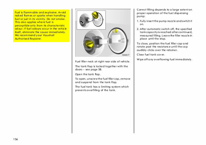
156
Fuel filler neck at right rear side of vehicle.
The tank flap is locked together with the doors – see page 58.
Open the tank flap .
To open, unscrew the fuel filler cap , remove and suspend from the tank flap.
The fuel tank has a limiting system which prevents overfilling of the tank.
Correct filling depends to a large extent on proper operation of the fuel disp ensing pump:
1. Fully insert the pump nozz le and switch it on.
2. After automatic switch off, the specified tank capa city is reached after continued, mea sured filling. Leave the filler nozz le in place until the stop.
To close, position the fuel filler cap a nd rotate past the resistanc e until the ca p audibly clicks over the reta iner.
C lose fuel tank cover.
Wipe off a ny overflowing fuel immediately .
Fuel is flamm able and explosive. Avoid naked flam es or sparks when handling fuel or just in its vicinity. Do not smoke. This also applies where fuel is perceptible only from its characteristic od our. I f fuel odours occur in the vehic le itself, eliminate the cause immed iately. We recom mend your Vauxhall Authorised Repairer.
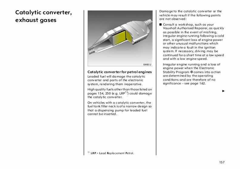
157
Catalytic converter, exhaust gases
Catalytic converter for petrol engines Leaded fuel will da mage the cata lytic converter and parts of the electronic system, rend ering them inoperative.
High quality fuels other than those listed on pages 154, 250 (e.g. LRP1)) could damag e the catalytic converter.
On vehicles with a c atalytic converter, the fuel ta nk filler nec k is of a narrow design so that a dispensing pump for leaded fuel cannot b e inserted .
Dama ge to the catalytic converter or the vehicle m ay result if the following points are not observed :
z Consult a workshop, such as your Vauxhall Authorised Repairer, as quic kly as possible in the event of misfiring, irregular engine running following a cold start, a significant loss of engine power or other unusual malfunctions which may indica te a fa ult in the ignition system. If necessary, d riv ing may be continued for a short time at a low speed and with a low engine speed.
Irregular engine running a nd a loss of engine power when the Electronic Stability Program 3 comes into a ction are d eterm ined by the operating cond itions and are therefore of no significance – see page 162.
6
1) LRP = Lead Replacement Petrol.
158
z If unburned fuel enters the catalytic converter, this may result in overheating and irreparable d amage to the cata lytic converter.
You should therefore avoid unnecessarily long use of the starter when sta rting off, running the tank dry (an irregular fuel sup ply will lead to overheating) and starting the eng ine by pushing or towing.
z If the em ission c ontrol indicator Z flashes, slow down until the flashing stop s and the control indicator is steady. Consult a workshop immediately. We rec om mend your Vauxhall Authorised Repairer. For emission control indicator Z – see page 159.
Catalytic converter for diesel engines Dama ge to the catalytic converter or the vehicle m ay result if the following points are not observed :
z Consult a workshop, such as your Vauxhall Authorised Repairer, as quic kly as possible in the event of irregular engine running, a significant loss of engine power or other unusual malfunctions. If necessary , driving m ay be continued for a short time at a low speed and with a low engine speed.
Irregular engine running a nd a loss of engine power when the Electronic Stability Program 3 comes into a ction are d eterm ined by the operating cond itions and are therefore of no significance – see page 162.
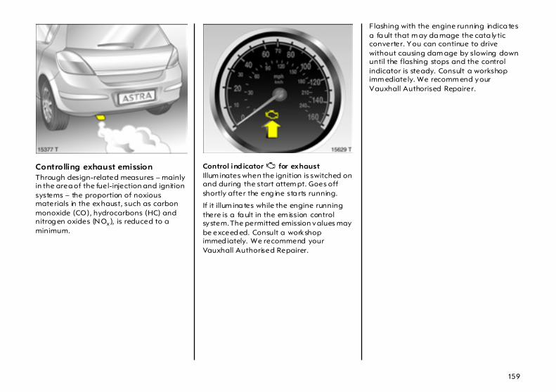
159
Controlling exhaust emission Through design-related measures – mainly in the area of the fuel-injection and ignition systems – the proportion of noxious materials in the exhaust, such as carbon monoxide (CO), hydrocarbons (HC) and nitrog en oxides (NOx ), is reduced to a minimum.
Control ind icator Z for exhaust Illum inates when the ignition is switched on and during the start attem pt. Goes off shortly after the eng ine sta rts running.
If it illum ina tes while the engine running there is a fa ult in the em ission control system. The permitted emission values may be exceed ed. Consult a workshop immed iately. We recommend your Vauxhall Authorised Repairer.
Flashing with the engine running indica tes a fa ult that m ay da mage the cata lytic converter. You can continue to drive without causing dam age by slowing down until the flashing stops and the control indicator is steady. Consult a workshop imm ediately. We recomm end your Vauxhall Authorised Repairer.
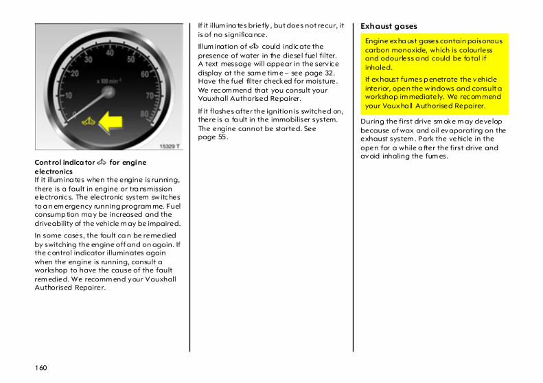
160
Control indica tor A for engine electronics If it illum ina tes when the engine is running, there is a fault in engine or tra nsmission electronic s. The electronic system sw itc hes to a n em ergency running program me. Fuel consump tion ma y be increased and the driveability of the vehicle m ay be impaired.
In some cases, the fault ca n be remedied by switching the engine off and on again. If the c ontrol indicator illuminates again when the engine is running, consult a workshop to have the cause of the fault rem edied. We recomm end your Vauxhall Authorised Repairer.
If it illum ina tes briefly , but does not recur, it is of no significa nce.
Illum ination of A could ind ic ate the presence of water in the diesel fuel filter. A text message will appear in the serv ic e display at the sam e tim e – see page 32. Have the fuel filter checked for moisture. We rec om mend that you consult your Vauxhall Authorised Repairer.
If it flashes after the ignition is switched on, there is a fa ult in the immobiliser system. The engine cannot be started. See page 55.
Exhaust gases
During the first drive sm oke m ay develop because of wax and oil evaporating on the exhaust system . Park the vehicle in the open for a while a fter the first drive and avoid inhaling the fum es.
Engine exha ust gases contain poisonous carbon monoxide, which is colourless and odourless a nd could be fa tal if inhaled.
If exhaust fumes p enetrate the vehicle interior, open the w indows and consult a workshop im mediately. We rec om mend your Vauxha ll Authorised Repairer.
161
Maintenance Have all maintenance work carried out at the intervals specified by Vauxhall. We recom mend that you entrust this work to your Vauxhall Authorised R epairer, who has proper equipment and trained personnel available. Electronic testing systems permit rapid dia gnosis and rem edy of faults. This way you can be certa in that a ll comp onents of the vehicle’s electrical, injec tion and ignition systems opera te correc tly , that your vehicle has a low level of pollutant emission and that the catalytic converter system will have a long service life.
You are thereby mak ing an important contribution towa rd s keep ing the air clean and compliance with em issions legislation.
Check ing and adjustm ent of the fuel-injection and ignition system s is p art of the scope of inspection. For this rea son you should have all maintenance work c arried out at the intervals specified in your Service Book let.

162
Drive Control Systems Interactive Driving System(IDS+ = Interactive Driving System) 3 IDS+ unites the sensors a nd control units of the Electronic Stability Program (ESP Plus), Anti-lock Brake System (ABS) and Continuous Damping Control (CDC). This prov ides both excellent driving dynam ics and grea ter safety.
Electronic StabilityProgram (ESPPlus) 3 ESPPlus improves d riv ing stab ility when necessary in any driving situation regardless of the type of road surface or tyre g rip . It also prevents the d rive wheels from spinning.
The system m onitors vehicle movements. As soon as the vehicle starts to swerve (understeers/oversteers) engine output is reduced (the sound of the engine cha ng es) and individual wheels are specifically braked . This considerab ly improves the driving stability of the vehicle on snow and ice and on wet or slippery road surfa ces.
ESPPlus is ready for opera tion as soon as the ignition is switched on and control indicator v goes out.
When the ESPPlus com es into action, v flashes.
The vehicle is now in a critical situa tion; ESPPlus a llows you to keep control of the vehicle a nd reminds you to m atch your speed to the road conditions.
Do not let this special safety feature tempt you into taking risks when driving.
Tra ffic safety can only b e ac hieved by adopting a responsible d riv ing sty le.
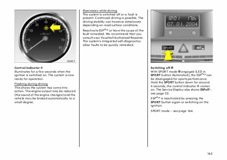
163
Control indica tor v Illuminates for a few seconds when the ignition is switched on. The system is now rea dy for opera tion.
Flashing during drivingThis shows the system has com e into action. The engine output may be reduced (the sound of the engine cha nges) a nd the vehic le ma y be braked automatically to a small degree.
Illum inates while drivingThe system is switched off or a fault is present. Continued driving is possible. The driving sta bility can however d eteriorate depending on road surface conditions.
Reactiva te ESPPlus or have the ca use of the fa ult remedied. We recommend tha t you consult your Va uxha ll Authorised Repairer. The system’s integ ra ted self-diagnostics allow faults to be quickly remedied.
Sw itching off 3 With SPOR T mode 3 enga ged (LED in SPORT b utton illuminated ), the ESPPlus can be disengaged for sports perform ance. Hold the SPORT button down for around 4 seconds, the control indicator v comes on. The Serv ice Displa y also shows ESPoff – see page 32.
ESPPlus is reactivated by pressing the SPORT button a gain or sw itching on the ignition.
SPORT mode – see p age 164.
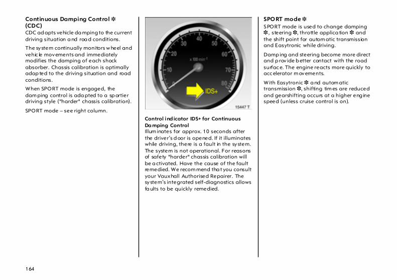
164
Continuous Damping Control 3 (CDC) CDC ad apts vehicle da mping to the current driving situation a nd roa d conditions.
The system continually monitors w heel and vehic le movements and immediately modifies the damping of each shock absorber. Chassis calibration is optimally adap ted to the driving situation and road conditions.
When SPORT mode is engaged, the dam ping control is ada pted to a sp ortier driving style ("harder" chassis calibration).
SPORT mode – see right column.
Control ind icator IDS+ for Continuous Da mping Control Illum inates for approx. 10 seconds after the driver’s d oor is opened. If it illuminates while driving, there is a fault in the system. The system is not operational. For reasons of safety "harder" chassis calibration will be a ctivated. Have the cause of the fault remedied. We recom mend tha t you consult your Vauxhall Authorised Repairer. The system’s integrated self-diagnostics allows fa ults to be quickly remedied.
SPO RT mode 3 SPORT mode is used to change damping 3 , steering 3, throttle applica tion 3 and the shift point for autom atic transmission and Easytronic while driving.
Damp ing and steering become more direct and p rov ide b etter contact with the road surfac e. The engine reacts more quickly to acc elerator m ovements.
With Easytronic 3 a nd autom atic transmission 3, shifting tim es are reduced and gearshifting occurs at a higher eng ine speed (unless cruise control is on).
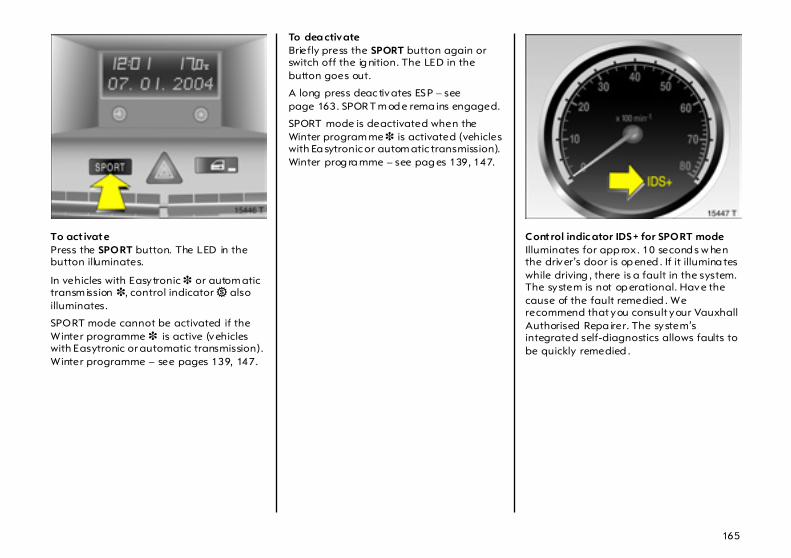
165
To act ivate Press the SPORT button. The LED in the button illuminates.
In vehicles with Easytronic 3 or autom atic transm ission 3, control indicator 1 also illuminates.
SPORT mode cannot be activated if the Winter programme 3 is active (vehicles with Easytronic or automatic transmission). Winter programme – see pages 139, 147.
To dea ctivateBriefly press the SPORT button again or switch off the ig nition. The LED in the button goes out.
A long press deac tivates ESP – see page 163. SPOR T m od e rema ins engaged.
SPORT mode is deactivated when the Winter program me 3 is activated (vehicles with Ea sytronic or autom atic transmission). Winter prog ra mme – see pag es 139, 147.
Control indic ator IDS + for SPORT modeIlluminates for app rox . 10 second s w hen the driver’s door is op ened . If it illumina tes while driving , there is a fault in the system. The system is not op erational. Have the cause of the fault remedied . We recommend that you consult your Vauxhall Authorised Repa irer. The system’s integrated self-diagnostics allows faults to be quickly remedied .
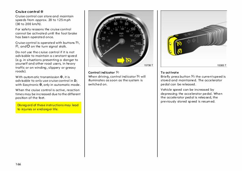
166
Cruise control 3 Cruise control can store and maintain speeds from approx. 20 to 125 m ph (30 to 200 km/h).
For safety reasons the cruise control cannot be activated until the foot brake has been operated once.
Cruise control is operated with buttons m , g, and § on the turn signal stalk.
Do not use the c ruise control if it is not adv isable to maintain a c onstant sp eed (e.g. in situations presenting a danger to yourself and other road users, in heavy traffic or on winding , slippery or greasy roads).
With autom atic transmission 3 , it is adv isable to only use cruise control in D; with Easytronic 3, only in automatic mode.
When the cruise control is active, reaction times may be increased due to the different position of the feet.
Control ind icator m When driving, control ind icator m will illuminates as soon as the system is switched on.
To act ivate Briefly press button m: the current speed is stored and maintained. The accelerator pedal can be released .
Vehicle speed can be increased by depressing the accelerator pedal. When the accelerator ped al is relea sed, the previously stored sp eed is resum ed.
Disreg ard of these instructions may lead to injuries or end ang er life.
167
Incr ease With cruise control active, hold down button m or briefly press it repea tedly: speed is increased continuously or in steps of 1.2 mph (2 km/h) without using the accelerator pedal.
When button m is released the current speed is stored and m aintained.
Decelera te With cruise control active, hold down button g or briefly press it repeatedly: speed is reduced continuously or in steps of 1.2 mph (2 km/h).
When button g is released the current speed is stored and m aintained.
To dea ctivate Briefly press button §: Cruise control is switched off, control indica tor m goes out and the vehicle slowly decelerates. To continue driv ing , depress the accelerator pedal in the usual manner.
For reasons of safety, c ruise control deactivates under certain driving conditions.
For example:
z the vehicle’s speed drops below a pprox. 20 mph (30 km/h) or
z the brake peda l is depressed or
z the clutch p edal is depressed or
z selector lever of automatic transm ission 3 or Ea sytronic 3 in N.
Resuming the stored speed Briefly press button g at a sp eed above 20 mph (30 km/h): the speed selected before the cruise control w as switc hed off is resumed.
The value of the stored speed is deleted when the ignition is turned off.

168
Parking distance sensors 3 The parking distance sensor m akes reverse parking easier by measuring the distance between the vehicle and an obsta cle in the rea r, and giving an acoustic signal in the passenger com partment.
The system record s the distance using four sensors in the rear bumper.
To activateThe parking d istance sensor system activates a utoma tica lly when the ig nition is switched on and reverse gear is eng aged.
Its op erational readiness is indicated by illumination of the LED in the button.
If the vehicle approaches an obstacle when reversing, a series of signals can be hea rd in the vehicle interior. The interval b etween the signals becomes shorter as the distance is reduced. If the distance is less than 30 cm, the sig nal will be continuous.
To deact ivateThe system deactivates automatically when reverse gear is disengaged .
To deactivate the system when reverse gear is engag ed, press button r. The LED in the button goes out.
To reactivate, press button r a gain.
Under certain circumstances, various reflective surfaces on objec ts or clothing as well a s external noise sources may cause the system to fail to detect obstacles. For this rea son, care must be taken when reversing even if the Pa rk ing distance sensor is operational. This is of particula r importance w hen in the vicinity of pedestrians.

169
Control indica tor r IlluminatedFault in the system. The system is not rea dy for operation. Have the fault rem edied. We recom mend tha t you consult your Vauxhall Authorised Repairer. The system ’s integrated self-diagnostics allows faults to be quickly remedied.
If it flashesThe fault is d ue to sensors obstructed with snow or ice. The sensors must be undam aged a nd free of d irt, snow and ic e.
Interference due to external sources of ultra sound (e.g . pneum atic drills, rota ry machines). Once the source of interference is removed, the system will operate normally .
Carava n/t railer tow ing equipm ent 3, ca ravan/tra iler towing The system automatically detects if a towbar is properly fitted to the vehicle.
When towing, the parking distance sensor is automatically deactiva ted w hen the trailer cable is p lugg ed into the socket.
Fitting rear load racks 3 Rear load racks, e.g . bicycle racks, fitted nea r the sensors could disrupt the system .
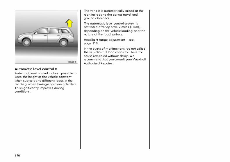
170
Autom atic level control 3 Autom atic level control makes it possible to keep the height of the vehicle constant when subjected to different loads in the rea r (e.g . when towing a caravan or trailer). This significantly improves driving conditions.
The vehic le is automatically ra ised at the rear, increasing the spring tra vel and ground c learance.
The automatic level control system is activated after ap prox . 2 miles (3 km), depending on the vehicle load ing and the na ture of the road surface.
Head lig ht range adjustment – see page 110.
In the event of m alfunctions, do not utilise the vehicle’s full load capa city. H ave the cause rem edied without delay . We recommend that you consult your Vauxhall Authorised Repairer.
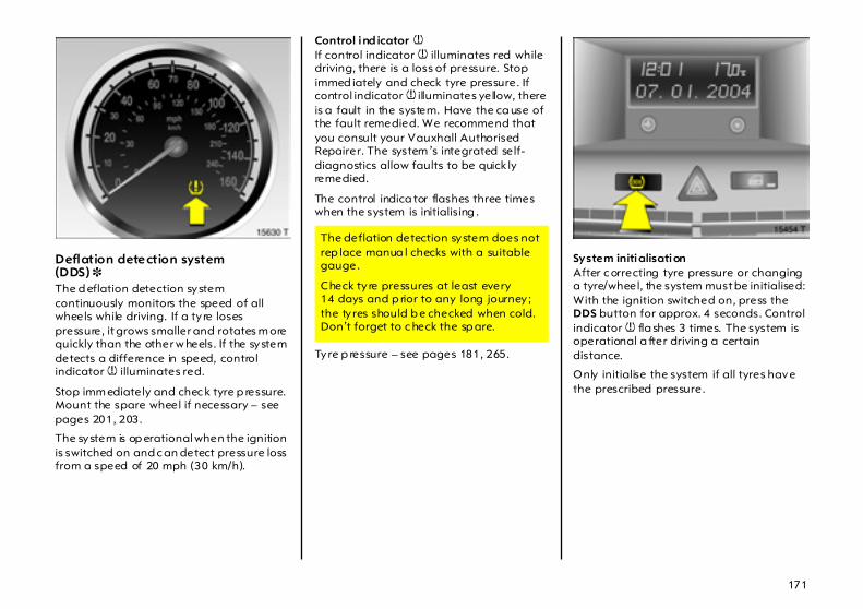
171
Deflation detection system(DDS) 3 The d eflation detection system continuously monitors the speed of all wheels while driving. If a ty re loses pressure, it grows smaller and rotates m ore quickly than the other w heels. If the system detects a difference in speed, control indicator w illuminates red.
Stop imm ediately and chec k tyre p ressure. Mount the spare wheel if necessary – see pages 201, 203.
The system is op erational when the ignition is switched on and c an detect pressure loss from a speed of 20 mph (30 km/h).
Control ind icator w If control indicator w illuminates red while driving, there is a loss of pressure. Stop immed iately and check tyre pressure. If control indicator w illuminates yellow, there is a fault in the system. Have the ca use of the fault remedied. We recommend that you consult your Vauxhall Authorised Repairer. The system ’s integrated self-diagnostics allow faults to be quick ly remedied.
The control indica tor flashes three times when the system is initialising .
Tyre p ressure – see pages 181, 265.
System initialisationAfter c orrecting tyre pressure or changing a tyre/wheel, the system must be initialised: With the ignition switched on, press the DDS button for approx. 4 seconds. Control indicator w fla shes 3 times. The system is operational a fter driving a certain distance.
Only initialise the system if all tyres have the prescribed pressure.
The deflation detection system does not rep lace manua l checks with a suitable gauge.
Check ty re pressures at least every 14 days and p rior to any long journey ; the ty res should b e checked when cold. Don’t forget to c heck the sp are.
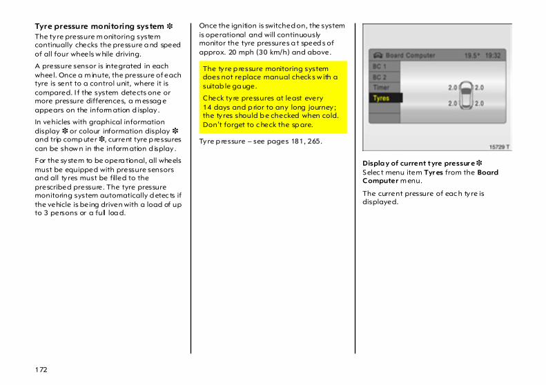
172
Tyre pressure monitoring system 3 The tyre pressure m onitoring system continually checks the pressure a nd speed of all four wheels w hile driving.
A pressure sensor is integrated in each wheel. Once a m inute, the pressure of each tyre is sent to a control unit, where it is compared. I f the system detects one or more pressure differences, a m essag e appears on the inform ation d isplay .
In vehicles with graphical information display 3 or colour information display 3 and trip comp uter 3, current tyre p ressures can be show n in the inform ation d isplay .
For the system to be opera tional, all wheels must be equipped with pressure sensors and all ty res must be filled to the prescribed pressure. The tyre pressure monitoring system automatically d etec ts if the vehicle is being driven with a load of up to 3 persons or a full loa d.
Once the ignition is switched on, the system is operational and will continuously monitor the tyre pressures a t speed s of approx. 20 mph (30 km/h) and above.
Tyre p ressure – see pages 181, 265.
Displa y of current tyre pressur e 3 Selec t menu item Tyr es from the Board Computer m enu.
The current pressure of eac h ty re is displayed.
The ty re p ressure monitoring system does not replace manual checks w ith a suitab le ga uge.
Check ty re pressures at least every 14 days and p rior to any long journey ; the ty res should b e checked when cold. Don’t forget to c heck the sp are.

173
Warning m essagesA message is given on the inform ation display to w arn of inconsistent ty re pressures. In some versions, the message is displayed in abbreviated form.
For example, the following m essa ges can be d isplayed:
Tyr e Pressurecheck rea r leftturn (value in b ar)
A graphic 3 indica ting the left rear tyre is shown together with the current ty re pressure: S light pressure deviation. Reduce speed. Chec k pressure at next op portunity with appropriate g auge a nd correct if necessary.
On the colour information disp la y this report will app ear in yellow.
Attention!Front left tyre p ressure loss (va lue in bar)
A grap hic 3 indicating the front left tyre is show n tog ether with the current tyre pressure: Significa nt pressure dev iation or direct pressure loss! Steer out of flow of traffic as quickly as possible without end angering other drivers. Stop and check tyres. M ount spa re wheel if necessary – see pag es 201, 203.
On the colour informa tion display this report will appear in red.
Acknowledgem ent of warnings – see pag e 42.
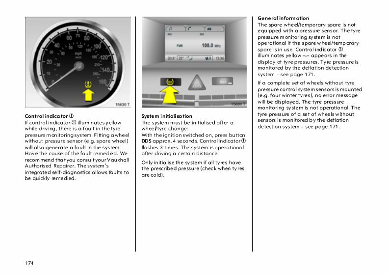
174
Control indica tor w If control indicator w illuminates yellow while driv ing , there is a fault in the ty re pressure m onitoring system. Fitting a wheel without pressure sensor (e.g. spare wheel) will also generate a fault in the system. Have the cause of the fault remed ied. We recom mend tha t you consult your Vauxhall Authorised Repairer. The system ’s integrated self-diagnostics allows faults to be quickly remedied.
System initiali sa tionThe system m ust be initialised after a wheel/tyre change: With the ignition switched on, press button DDS app rox . 4 second s. Control indicator w flashes 3 times. The system is operationa l after driving a certain distance.
Only initialise the system if all ty res have the prescribed pressure (chec k when tyres are cold).
General inform ation The spare wheel/temporary spare is not equipped with a pressure sensor. The ty re pressure m onitoring system is not operational if the spare w heel/temp orary spare is in use. Control ind ic ator w illuminates yellow –.– appears in the display of ty re p ressures. Tyre pressure is monitored by the deflation detection system – see page 171.
If a complete set of w heels without tyre pressure control system sensors is mounted (e.g. four winter ty res), no error message will be displayed. The tyre pressure monitoring system is not operational. The tyre pressure of a set of wheels w ithout sensors is monitored b y the deflation detection system – see page 171.

175
Sensors for the tyre pressure monitoring system c an be retrofitted. We recomm end that you consult your Vauxhall Authorised Repairer.
When ma nually check ing tyre pressure w ith a p ressure gauge, screw the adapter onto the valve. Tyre pressure – see pa ge 265.
The tyre pressure monitoring system valve cores and sealing rings must be replaced each time the tyres are changed. We recommend that you consult your Vauxhall Authorised Repairer.
The use of comm ercially a vailable liquid filled run-flat systems or repair k its can impair the function of the system. Vauxhall-app roved system s c an be used .
Radio transmitters (e.g. radio hea dphones, walkie-talk ies) operated in the a rea could cause interferenc e in the tyre pressure monitoring system.

176
Brakes Brake system The brakes are a n important factor for tra ffic safety .
To improve effectiveness, do not brake unnec essarily ha rd for the first 125 miles (200 km) after new brake p ads ha ve been fitted.
Brake pad wear must not exceed a specified lim it. Reg ular maintenance as detailed in the Service Booklet is therefore of the utmost im porta nce for traffic sa fety.
Have worn brake pads replaced. We recommend that you consult your Vauxhall Authorised Repairer, who will fit pads that ha ve b een tested a nd approved by Vauxhall and guarantee optimum braking power.
Brake pads worn to their minimum thickness generate a grinding noise. Continued driving possible. H ave the brake pads replac ed a s soon as possible by a workshop. We recom mend your Vauxhall Authorised Repairer.
Brake assi st Rapid powerful applica tion of the brake pedal automatically applies m aximum brak ing force amp lification to achieve the shortest possible b ra king dista nce under full braking (brake assistant).
Maintain steady pressure on the b rake pedal for as long as full-on brak ing is to continue. When the brake pedal is released, the m aximum b ra ke force am plification is taken away.
Ad aptive brake light During full-on brak ing, all three brake lights flash for the dura tion of ABS control.
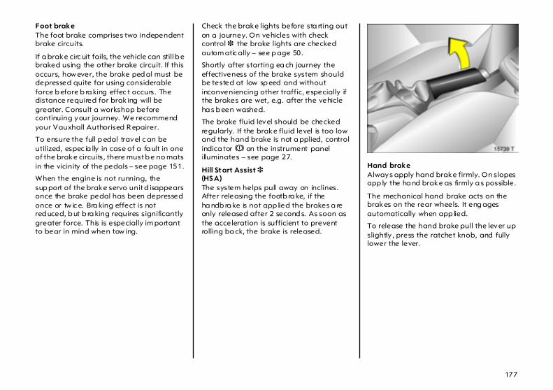
177
Foot brake The foot brake comprises two independent brake circuits.
If a brake circ uit fails, the vehicle can still b e braked using the other brake circuit. If this occurs, how ever, the brake ped al must be depressed quite far using considerable force b efore b ra king effec t occurs. The distance required for brak ing will be greater. Consult a workshop before continuing your journey. We recommend your Vauxhall Authorised R epairer.
To ensure the full p edal travel c an be utilized, espec ia lly in case of a fa ult in one of the brake circuits, there must b e no mats in the vicinity of the pedals – see page 151.
When the engine is not running, the sup port of the brake servo unit d isappears once the brake pedal has been depressed once or tw ic e. Bra king effect is not red uced, b ut b ra king requires significantly greater force. This is especially im portant to bear in mind when tow ing.
Check the brake lights before sta rting out on a journey. On vehicles with check control 3 the brake lights are checked autom atic ally – see p age 50.
Shortly after starting ea ch journey the effectiveness of the brake system should be tested at low sp eed and without inconveniencing other traffic, especially if the brakes are wet, e.g. after the vehicle ha s b een washed.
The brake fluid level should be checked regularly. If the brake fluid level is too low and the hand brake is not a pplied, control indica tor R on the instrument panel illuminates – see page 27.
Hill Start Assist 3(HS A) The system helps pull away on inclines. After releasing the footb ra ke, if the ha ndb ra ke is not app lied the brakes a re only released after 2 second s. As soon as the acceleration is sufficient to prevent rolling ba ck, the brake is released.
Hand brake Always apply hand brake firmly. On slopes app ly the ha nd brake as firmly a s possible.
The mechanical hand brake acts on the brakes on the rear wheels. It eng ages automatically when app lied.
To release the hand brake pull the lever up slightly , press the ratchet knob, and fully lower the lever.

178
Brake system control indicator R The c ontrol indicator illumina tes when the ignition is switched on if the hand brake is applied or if the brake or clutch fluid level is too low. Brake fluid – see page 238.
ABS u The Anti-lock Brake System (ABS) continuously monitors the vehicle’s brake system and prevents the wheels from lock ing regardless of the roa d condition and tyre grip.
It starts to regulate the brak ing pressure as soon as a wheel shows a tendency to loc k. The vehic le remains steerable, even in the event of very heavy braking, for instance on b ends or when swerv ing to avoid a n ob stacle. Even in the case of full-on braking, the ABS m akes it possible to d rive round an obstacle without releasing the brakes.
AB S control is m ade apparent though a pulse in the brake pedal a nd the noise of the reg ulation process.
If the control ind icator illum inates when the hand brake is not applied : Stop. Interrup t your journey immediately. Consult a w orkshop. We recomm end your Vauxhall Authorised Repairer.
For optimum braking, keep the brake peda l fully dep ressed throughout the braking process, despite the fact that the peda l is p ulsating. Do not reduce the pressure on the pedal.
Do not let this special safety feature tempt you into taking risks when driving.
Tra ffic safety can only b e ac hieved by adopting a responsible d riv ing sty le.

179
Control indica tor u for ABS The control ind ic ator illum ina tes for several seconds when the ignition is switched on and the system undergoes a self-check at the same time (may be audible). The system is ready for operation when the control indica tor goes out.
If the control indicator does not g o out after a few seconds, or if it illuminates while driving, there is a fault in the ABS. The brake system remains operational without ABS regulation.
You can continue driving, prov ided you drive with care a nd antic ipation.
Have the cause of the fa ult remedied. We recommend that you consult your Vauxhall Authorised Repa irer. The system’s integrated self-diagnostics allows faults to be quickly remedied .
If there is a fault in ABS, the wheels may be subjec t to locking d ue to brak ing that is heavier tha n normal. The adva ntages of ABS are no longer op erational. The vehicle ca n no longer be steered and may swerve.

180
Wheels, tyres Tyres See pag e 265 for suitable ty res and restrictions.
Tyres fitted in the factory are adapted to the chassis and provid e optimum driving comfort and sa fety.
Changing tyre/wheel type Before switching to different tyres or wheels, seek advice on the technical possibilities. We recommend that you consult your Va uxha ll Authorised Repairer, who will be able to advise you of any necessary mod ifications.
If tyres of a different size than those fitted at the factory are used, the electronic speedom eter may require reprogramming to ensure that the correct sp eed is displayed.
Vehicles with tyre pressure monitoring system 3If winter tyres or tyres of a different size are fitted, tyre pressure monitoring system sensors ca n be retrofitted if so desired. Otherwise, the system w ill not indicate tyre pressure deviations. We recommend tha t you consult your Vauxhall Authorised Repairer.
Defla tion detection system 3 – see pag e 171, tyre pressure monitoring system 3 – see p age 172.
Use of unsuitab le tyres or wheels m ay lead to accidents and render the vehicle unroa dworthy .
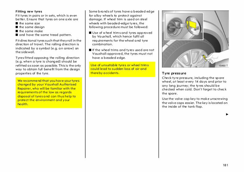
181
Fitting new tyres Fit tyres in pairs or in sets, which is even better. Ensure that tyres on one a xle are z the same size z the same design z the same make z and have the same tread pattern.
Fit direc tional tyres such that they roll in the direc tion of travel. The rolling d irection is indicated by a symbol (e.g. a n arrow) on the sidewall.
Tyres fitted opposing the rolling direction (e.g. when a tyre is chang ed) should be refitted a s soon as possible. This is the only way to obtain full benefit from the design properties of the tyre.
Some b ra nd s of tyres have a b eaded ed ge for a lloy wheels to protect against damage. If wheel trim is used on steel wheels with beaded-edg e tyres, the following procedure must be followed:
z Use of w heel trim s and tyres app roved by Va uxha ll, which hence fulfil all req uirements for the wheel a nd tyre combination.
z If the wheel trims and tyres used are not Vauxhall-approved, the tyres must not have a b eaded edge.
Tyre pressure Check ty re pressure, including the sp are wheel, a t least every 14 da ys and prior to any long journey ; the ty res should b e checked when cold. Don’ t forget to chec k the spare.
Use the valve cap key to make unscrewing the valve caps easier. The key is located on the inside of the tank flap.
6
We recommend that you have your tyres cha nged by your Vauxhall Authorised Repairer, who will be familiar with the requirements of the law as regards disposal of tyres a nd can thus help to protect the environment and your health.
Use of unsuitab le tyres or wheel trim s could lead to sudden loss of air and thereby a ccidents.
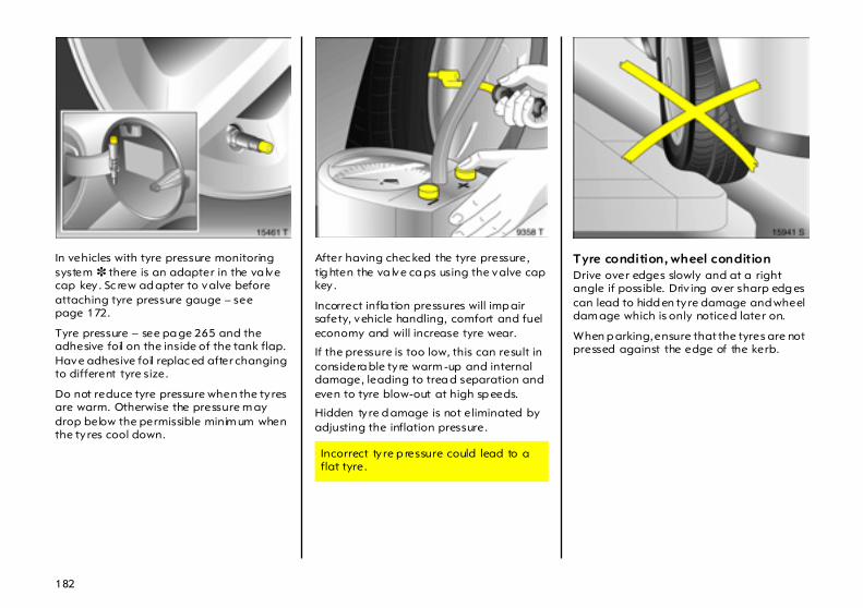
182
In vehicles with tyre pressure monitoring system 3 there is an adapter in the va lve cap key . Sc rew ad apter to valve before attaching tyre pressure gauge – see page 172.
Tyre pressure – see pa ge 265 and the adhesive foil on the inside of the tank flap. Have adhesive foil replac ed after changing to different tyre size.
Do not reduce tyre pressure when the ty res are warm. Otherwise the pressure m ay drop below the permissible minim um when the ty res cool down.
After having chec ked the tyre pressure, tig hten the va lve ca ps using the valve cap key .
Incorrect infla tion pressures will imp air safety, vehicle handling, comfort and fuel economy and will increase tyre wear.
If the pressure is too low, this can result in considera ble ty re warm -up and internal damage, leading to trea d separation and even to tyre blow-out at high sp eeds.
Hidden tyre d amage is not eliminated by adjusting the inflation pressure.
Tyre condition, wheel condition Drive over edges slowly and at a right angle if possible. Driv ing over sharp edg es can lead to hidd en tyre damage and wheel dam age which is only noticed later on.
When p arking, ensure that the tyres are not pressed against the edge of the kerb.
Incorrect ty re p ressure could lead to a flat tyre.
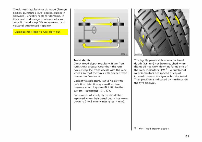
183
Check ty res regularly for da mage (foreign bodies, punctures, cuts, cra cks, bulges in sidewalls). Check w heels for dama ge. In the event of damage or abnormal w ear, consult a workshop. We rec om mend your Vauxhall Authorised Repairer.
Tr ead depth Check tread depth regularly. I f the front tyres show greater wear tha n the rea r tyres, swap the front wheels with the rear wheels so that the ty res with deeper tread are on the front ax le.
Correct ty re pressure. For vehicles with deflation detection system 3 or ty re pressure control system 3, initialise the system – see pa ges 171, 174.
For reasons of safety, ty res should be replaced when their tread depth has worn down to 2 to 3 mm (winter ty res: 4 mm ).
The legally permissible m inimum tread depth (1.6 mm) has been rea ched when the tread has worn down as far as one of the wear indica tors (TWI 1)). A numb er of wear indicators are spaced at equal interva ls around the tyre within the tread. Their p osition is indicated by markings on the tyre sidewall.
Da mage may lead to tyre blow-out.
1) TWI = Tread Wear In dicato r.
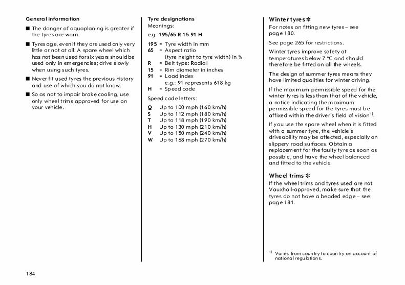
184
Genera l informa tion
z The danger of aquaplaning is greater if the tyres a re worn.
z Tyres ag e, even if they are used only very little or not at all. A spare wheel which has not been used for six yea rs should be used only in em ergenc ies; drive slow ly when using such tyres.
z Never fit used ty res the previous history and use of which you do not know.
z So as not to impair brake cooling, use only wheel trim s approved for use on your vehicle.
Tyre designations Meanings:
e.g. 195/65 R 15 91 H
195 = Tyre width in mm 65 = Aspect ratio
(tyre height to tyre width) in % R = Belt type: Radia l 15 = Rim diameter in inches 91 = Load index
e.g.: 91 represents 618 kg H = Sp eed code
Speed c od e letters:
Q Up to 100 m ph (160 km/h) S Up to 112 m ph (180 km/h) T Up to 118 m ph (190 km/h) H Up to 130 m ph (210 km/h) V Up to 150 m ph (240 km/h) W Up to 168 m ph (270 km/h)
Winter tyres 3 For notes on fitting new tyres – see pag e 180.
See page 265 for restrictions.
Winter tyres improve safety at temperatures b elow 7 °C and should therefore be fitted on all the wheels.
The design of summ er ty res means they have limited qualities for winter driving.
If the maxim um perm issible speed for the winter ty res is less than that of the vehicle, a notice indicating the m aximum permissible sp eed for the tyres must b e affixed within the driver’s field of v ision1).
If you use the spare wheel when it is fitted with a summer tyre, the vehicle’s driveability ma y be affected , especially on slippery road surfaces. Obtain a replacem ent for the faulty ty re as soon as possible, and ha ve the wheel balanced and fitted to the vehicle.
Wheel trims 3 If the wheel trims and tyres used are not Vauxhall-approved, ma ke sure that the tyres do not have a beaded edg e – see pag e 181.
1) Varies from coun try to coun try on account of national regu lation s.
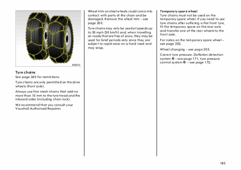
185
Tyre chains See page 265 for restric tions.
Tyre c hains are only permitted on the drive wheels (front ax le).
Always use fine mesh chains that add no more than 15 mm to the tyre tread and the inboard sides (including chain lock).
We recommend that you consult your Vauxhall Authorised Repairer.
Wheel trim on steel w heels could com e into contact with parts of the chain and be damaged. R emove the wheel trim – see page 203.
Tyre chains may only be used a t speeds up to 30 mp h (50 km/h) and, when travelling on roads that are free of snow, they may be used for brief periods only since they are subjec t to rapid wear on a hard road and may snap.
Tempora ry spar e w heel Tyre chains must not be used on the temporary spare wheel. If you need to use tyre chains after suffering a flat front tyre, fit the temporary spa re on the rear ax le and transfer one of the rea r wheels to the front axle.
For notes on the tem porary spare wheel – see page 202.
Wheel changing – see pag e 203.
Correct tyre pressure. Defla tion detection system 3 – see pa ge 171, tyre pressure control system 3 – see page 172.
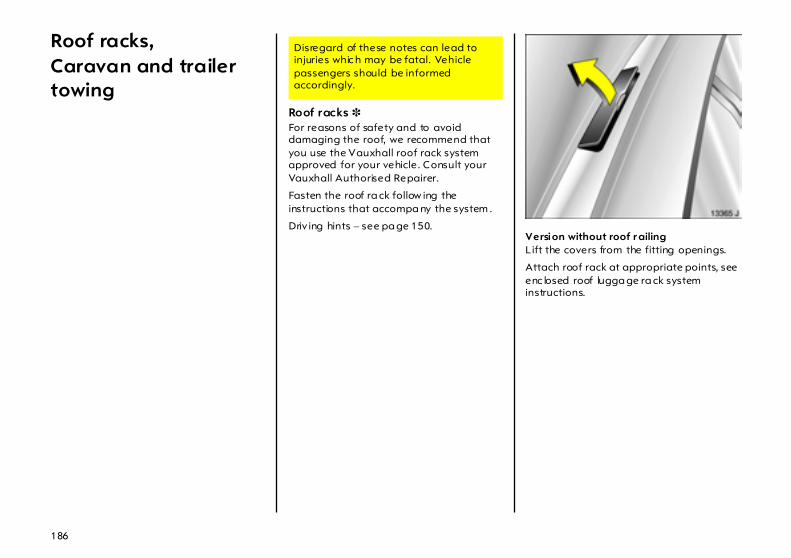
186
Roof racks,Caravan and trailer towing
Roof racks 3 For reasons of safety and to avoid damaging the roof, we recommend that you use the Vauxhall roof rack system approved for your vehicle. Consult your Vauxhall Authorised Repairer.
Fasten the roof ra ck follow ing the instructions that accompa ny the system .
Driv ing hints – see pa ge 150. Version without roof r ailing Lift the covers from the fitting openings.
Attach roof rack at appropriate points, see enc losed roof lugga ge ra ck system instructions.
Disregard of these notes can lead to injuries whic h may be fatal. Vehicle passengers should be informed accordingly.

187
Ver sion w ith roof ra iling 3 Attach roof rack to roof railing at points shown in fig ure, see enclosed roof luggage rack system instructions.
Towing equipment 3 Use only towing equipment that has been approved for your vehicle. We rec om mend entrusting the retrofitting of towing equipment to your Va uxha ll Authorised Repairer, who will ad vise you on any possible towed load increases. Your Vauxhall Authorised Repairer has instructions on how to install the towing equipment and make a ny necessary cha ng es to the vehicle that affect the cooling system , heat shield s or other equipment.
Do not m ount towing equipment to vehicles w ith Z 20 LEH1) eng ine.
For insta lla tion dim ensions of the trailer tow ing equipment – see pages 275, 276.
Towing equipment with detachable coupling ball bar 3 Stowage of coup ling ba ll bar In Hatch models, the coupling b all b ar is in a pouch, fastened in the lug gage compa rtm ent cargo box with a strap – see pag e 190.
In Estate models, the coupling ball bar is fastened with a stra p in a compartment in the spare wheel well of the luggag e compa rtm ent.
6
The coupling b all bar is to be rem oved when not towing.
1) Sales designation – s ee page 250.

188
Fitting the c oupling b all ba r Disengage and fold down the socket. Remove the sealing plug from the hole for the c oupling ba ll bar and stow it in the luggage compartment.
Check ing the tensioning of the coupling ball bar
z Red mark ing on turn knob p oints towards white marking on coupling ball bar.
z Gap of approx. 6 m illim etres between rotary knob and coupling ball bar.
z Key is in lock at position 1.
Otherwise, the coupling ball bar must b e tensioned b efore it is inserted into the coupling housing:
z Unlock coupling ball bar (key to position 1) – see Fig. 12416 T.
z Pull turn knob out and then turn it clockwise as far as it w ill go – see Fig. 12417 T.
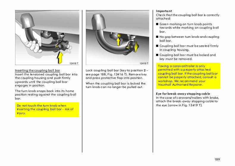
189
Inserting the coupling ba ll bar Insert the tensioned coupling ball bar into the c oupling housing a nd push firmly upwards until the coupling ball b ar enga ges in position.
The turn knob snaps back into its home position resting ag ainst the coupling b all bar.
Lock coup ling ball bar (key to p osition 2 – see p age 188, Fig. 12416 T). Rem ove key and press protective flap into position.
When the coupling ball ba r is locked the turn knob c an no longer be pulled out.
Importa nt Check tha t the coupling ball bar is correctly attached:
z Green marking on turn knob points tow ards white mark ing on coupling b all bar.
z No gap between turn knob and c oupling ball bar.
z Coupling ball ba r must b e sea ted firmly in coup ling housing.
z Coupling ball ba r must b e locked and key must be removed.
Eye for break-awa y stopp ing cab le In the ca se of c aravans/trailers with brake, attach the break-away stopping ca ble to the eye (arrow in Fig. 12419 T). Do not touch the turn knob w hen
inserting the coup ling ball bar - risk of injury.
Tow ing a caravan/trailer is only permitted with a p roperly attac hed coup ling ball bar. If the coupling ball b ar cannot be p roperly attached, consult a workshop. We rec om mend your Vauxhall Authorised Repairer.
190
Dismounting the coupling b all ba r Unlock coupling ball ba r (key to position 1 – see pa ge 188, Fig . 12416 T).
Pull out turn knob a nd then turn it clockwise as far as it will go. Pull coupling b all bar down out of the coupling housing and stow in compartment in the luggag e compartment – see pa ge 187.
Insert the sealing p lug in the hole for the coupling b all bar. Fold aw ay the socket – see p age 188, Fig. 15463 T.
Do not use steam-jet cleaners or other high-pressure cleaners to clean the coupling b all bar.
Stowage of coupling ball bar Hatch Stow the coup ling ball b ar in the pouch and fasten it in the lug gage compartment cargo box with the strap.
Estate Stow the coupling ball b ar in the compa rtm ent in the sp are wheel well of the luggage compa rtm ent, fastening it with the strap.
191
Caravan and trailer loads1)
The p ermissible caravan/trailer loads are vehic le- and engine-dependent maxim um values w hich m ust not be exceeded . The actual c aravan/trailer load is the difference between the actual g ross weight of the carava n/trailer and the actual coupling soc ket load with the caravan/trailer coupled. When the c aravan/trailer load is being checked, therefore, only the carava n/trailer wheels – and not the jockey wheel – must be standing on the weighing appa ra tus.
The p ermissible caravan/trailer loads for your vehicle are given in the vehicle documents. Unless otherwise stated, they are valid for grad ients up to max. 12 %.
The permissible caravan/trailer load should be fully utilised only by d rivers who are adeq uately experienced in towing large or heavy caravans/trailers.
The permitted caravan/trailer load applies up to the spec ified incline and up to an altitude of 1000 metres above sea level. Since engine power decreases as altitude increases because of the air b ecoming thinner, therefore reducing climbing ability , the permitted towing w eight also decreases by 10 % for every 1000 m etres of additiona l altitude. The towing weig ht does not ha ve to b e reduced when driving on roads with slight inc lines (less than 8 %, e. g. motorways).
The actual caravan/trailer load p lus the actual g ross vehicle weight of the tow vehicle m ust not exceed the maxim um permitted towing weight. For example, if the permitted gross vehicle weight is utilised, the tra iler/ca ra van load must only be used until the m aximum permitted towing weight is reached . The maximum permitted towing weight is shown on the identification plate – see pa ge 248.
1) Observe nation al regulations.

192
Coupling socket load The c oupling socket load is the load exerted by the trailer/caravan on the coupling ball. It can b e varied by changing the w eight distribution when loa ding the trailer/caravan.
The ma ximum permissible coup ling socket load (75 kg) is specified on the towing equipm ent identification plate and in the vehic le documents. Alw ays aim for the maximum load, especia lly in the ca se of heavy caravans/trailers. The c oupling soc ket load should never fall below 25 kg.
When mea suring the coup ling socket load, make sure that the drawbar of the loa ded trailer/caravan is at the sa me height as it will be when the trailer/caravan is coupled with the towing vehicle load ed. Particularly important for trailers/caravans w ith tandem axle.
Rear axle load during towing With a tra iler coupled and the towing vehicle fully loaded (including a ll oc cup ants) the permissible rear axle load (see identification plate or vehic le docum ents) may be exceeded by 65 kg and perm issible gross vehicle weight by 45 kg for the Hatch. For the Estate, the permissib le rear axle load m ay be exc eeded by 60 kg a nd the permissible gross vehicle weight by 30 kg. If the permissib le rear axle load is exceeded, a maximum speed of 100 km/h applies. If na tional regulations specify a lower maximum speed for vehicles towing a tra iler, this must be observed.
Tyre pressure Increase the ty re p ressure on the towing vehicle to the value specified for a full load – see page 265. Check the pressure of the spare wheel and caravan/trailer w heels.
Trailer Stability Assist 3(TSA) TSA monitors vehicle movements when towing a caravan or trailer. If the system detects lurching movem ents, engine power is reduced and the vehic le/trailer comb ination is selec tively braked until the lurching ceases.
193
Driving characteristics, towing tips In the case of cara vans/trailers with b ra kes, attach breakaway stop ping cable to eye.
Before attaching the ca ra van/trailer, lubricate the ball of the caravan/tra iler towing device. However, do not lub rica te the b all if a stabiliser, which acts on the coupling ball, is being used to da mp hunting.
Check cara van/trailer lig hting b efore starting to drive. The fog tail lights on the vehic le are deactivated when towing a carava n or tra iler.
Pa rk ing distance sensor 3 is dea ctivated when towing.
Handling is greatly influenced by the loa ding of the caravan/trailer. Loads should therefore be secured so that they cannot slip and be p laced in the centre of the caravan/trailer if p ossible, i.e. above the axle.
In the case of trailers with low driving stability or cara vans with a perm itted gross vehicle weig ht of over 1300 kg (H atch)/1200 kg (Estate), do not exceed a sp eed of 50 mph (80 km /h); the use of a friction-type stabiliser is highly recommend ed.
Do not d rive faster than 50 mph (80 km/h) if possible, even in countries where hig her speeds are permitted.
Make sure that you have enough room when cornering and a void sud den manoeuvres.
If the caravan/trailer starts to sway, drive more slowly , do not attem pt to correct the steering and brake sha rp ly if necessary .
If it is necessary to apply the brakes fully , depress the brake pedal a s hard as possible.
Remem ber that the braking d istance for vehicles towing carava ns/trailers with and without brake is always greater than that for vehic les not tow ing a caravan/trailer.
6
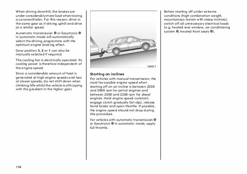
194
When driving downhill, the brakes a re under considerab ly m ore load when towing a ca ravan/trailer. For this rea son, drive in the same gear as if driv ing uphill and drive at a similar speed.
Autom atic transm ission 3 or Easytronic 3 in automatic mode will automatically select the driving prog ra mme with the optimum engine brak ing effect.
Gear position 3, 2 or 1 can also be manually selected if required.
The cooling fan is electrically operated. Its cooling power is therefore independent of the engine speed.
Since a considerable amount of heat is generated at high engine sp eed s a nd less at slower speeds, d o not shift down when climbing hills whilst the vehicle is still coping with the g ra dient in the higher gea r.
Starting on inclines For vehicles with manual transm ission, the most favourable eng ine speed when starting off on an incline is between 2500 and 3000 rpm for petrol engines and between 2000 and 2200 rpm for diesel engines. Hold engine speed constant, engage clutch gradually (let slip), release ha nd brake and open throttle. If possible, the engine speed should not drop d uring this procedure.
For vehicles with automatic transmission 3 or Easytronic 3 in automatic mode, apply full throttle.
Before starting off under extreme conditions (high combination weight, mountainous terrain w ith steep inclines), switch off all unnecessary electrical loads (e.g. heated rear window, air conditioning system 3, heated front seats 3).
195
Self-help
Diesel fuel system, bleeding Never let the tank run dry ! If c ontrol indica tor Y illuminates, refuel as soon a s possible. Refuel immediately if it fla shes.
It is p ossib le to restart the engine if the ta nk ha s b een run dry . A delayed start is to be exp ected. Switch on the ignition three tim es for a pprox. 15 seconds. Then attempt to start the engine for a pprox. 40 seconds. If the engine does not start, wait a few minutes and try ag ain. If the engine d oes not start, consult a workshop. We recommend your Vauxhall Authorised Repairer.
Do not start with quick charger This prevents d amage to electronic components.
Do not start bypushing or towing Because your vehicle is fitted with a catalytic converter, it must not be started by pushing or towing. See page 157.
Disregard of these notes can lead to injuries whic h may be fatal. Vehicle passengers should be informed accordingly.
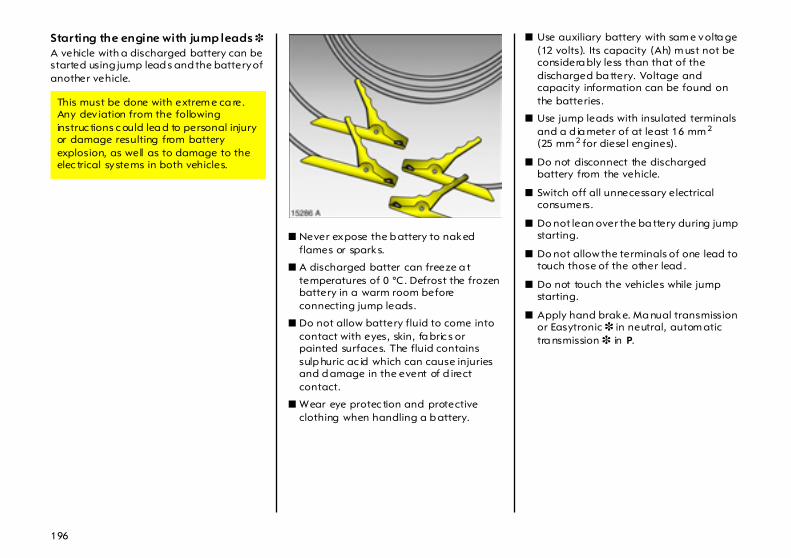
196
Starting the engine with jump leads 3 A vehicle with a discharged battery can be started using jump lead s and the battery of another vehicle.
z Never expose the b attery to naked flames or sparks.
z A discharged batter can freeze a t temperatures of 0 °C. Defrost the frozen battery in a warm room before connecting jump leads.
z Do not allow battery fluid to come into contact with eyes, skin, fa bric s or painted surfaces. The fluid contains sulp huric ac id which can cause injuries and d amage in the event of d irect contact.
z Wear eye protec tion and protective clothing when handling a b attery.
z Use auxiliary battery with sam e volta ge (12 volts). Its capacity (Ah) m ust not be considera bly less than that of the discharged ba ttery. Voltage and capacity information can be found on the batteries.
z Use jump leads with insulated terminals and a d ia meter of at least 16 mm 2 (25 mm 2 for diesel engines).
z Do not disconnect the discharged battery from the vehicle.
z Switch off all unnecessary electrical consumers.
z Do not lean over the ba ttery during jump starting.
z Do not allow the terminals of one lead to touch those of the other lead .
z Do not touch the vehicles while jump starting.
z Apply hand brake. Ma nual transmission or Easytronic 3 in neutral, autom atic tra nsmission 3 in P.
This must be done with extrem e ca re. Any dev iation from the following instruc tions c ould lea d to personal injury or damage resulting from battery explosion, as well as to damage to the elec trical systems in both vehicles.
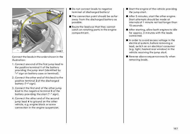
197
Connect the lea ds in the order shown in the illustration:
1. Connect one end of the first jump lead to the positive terminal 1 of the battery prov iding the jump start (identified by "+" sign on battery case or terminal).
2. Connect the other end of this lea d to the positive terminal 2 of the discharged battery ("+" sign).
3. Connect the first end of the other jump lead to the negative terminal 3 of the battery prov iding the start ("–" sign).
4. Connect the other end of the second jump lead 4 to ground on the other vehicle, e.g. engine block or screw connection in the engine suspension.
z Do not connect leads to negative term inal of discharged battery!
z The connection p oint should be as far away from the discharged battery as possible.
z Route the lead s so that they cannot catch on rotating parts in the engine compa rtm ent.
z Start the engine of the vehicle prov iding the jump start.
z After 5 minutes, start the other engine. Start attempts should be made at intervals of 1 minute not last longer than 15 seconds.
z After starting, allow both eng ines to idle for approx. 3 m inutes with the leads connected.
z In order to a void excess voltage in the electric al system, b efore removing a lead, sw itc h on a n electrica l consumer (e.g. light, heated rear window) in the vehicle receiving the jump sta rt.
z Reverse above seq uence exac tly when removing leads.
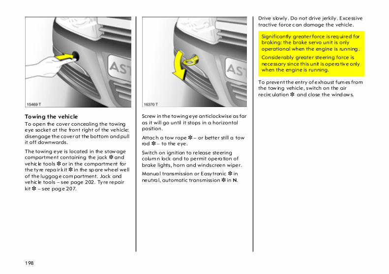
198
Towing the vehicle To open the cover concealing the towing eye socket at the front right of the vehicle: disengage the cover at the bottom and pull it off downwards.
The towing eye is located in the stow age compartment containing the jack 3 and vehic le tools 3 or in the compartment for the ty re repa ir k it 3 in the sp are wheel well of the luggag e com partment. Jack and vehic le tools – see page 202. Tyre repair kit 3 – see pag e 207.
Screw in the towing eye anticlockwise as far as it will go until it stops in a horizontal position.
Attac h a tow rope 3 – or better still a tow rod 3 – to the eye.
Switch on ignition to release steering colum n lock and to permit opera tion of brake lights, horn and windscreen wiper.
Manua l transmission or Easytronic 3 in neutra l, automatic transmission 3 in N.
Drive slowly . Do not drive jerkily . Excessive tractive force c an damage the vehicle.
To prevent the entry of exhaust fum es from the tow ing vehicle, switch on the air recirc ulation 3 and close the wind ow s.
Significantly greater force is req uired for braking: the brake servo unit is only operational when the engine is running .
Considerably greater steering force is necessary since this unit is opera tive only when the engine is running.
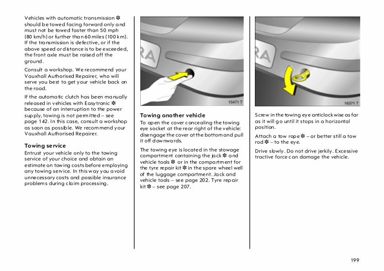
199
Vehicles with automatic transmission 3 should b e towed facing forward only a nd must not be towed faster than 50 mph(80 km/h) or further tha n 60 miles (100 km). If the tra nsmission is defective, or if the above speed or d istance is to be exceeded, the front axle must be raised off the ground .
Consult a workshop. We recommend your Vauxhall Authorised Repairer, who will serve you best to get your vehicle back on the road.
If the automa tic clutch has been ma nually released in vehicles with Easytronic 3 because of an interruption to the power sup ply, towing is not perm itted – see page 142. In this case, consult a workshop as soon as possib le. We recom mend your Vauxhall Authorised Repairer.
Towing service Entrust your vehicle only to the towing service of your choice and obtain an estimate on tow ing costs before employing any towing serv ice. In this w ay you a void unnecessary costs and possible insurance problem s during c la im processing .
Towing another vehicle To op en the cover c oncealing the towing eye socket at the rear right of the vehicle: disengage the cover at the bottom and pull it off d ow nwa rds.
The towing eye is located in the stowage compartment containing the ja ck 3 a nd vehicle tools 3 or in the compa rtm ent for the tyre repair kit 3 in the spare wheel well of the luggage compartment. Ja ck and vehicle tools – see page 202. Tyre rep air kit 3 – see page 207.
Screw in the towing eye anticlockwise as far as it will g o until it stops in a horizontal position.
Attach a tow rop e 3 – or better still a tow rod 3 – to the eye.
Drive slowly . Do not drive jerkily . Excessive tractive force c an damage the vehicle.
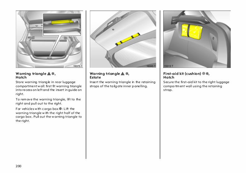
200
Warning triangle ¨ 3 ,Hatch Store warning triang le in rear luggage compartment w all: first fit warning triangle into recess on left and the insert in guide on right.
To rem ove the warning triangle, lift to the right and pull out to the right.
For vehicles w ith c argo box 3 : Lift the warning triangle w ith the right half of the cargo box. Pull out the w arning triangle to the right.
Warning triangle ¨ 3,Estate Insert the warning triangle in the retaining straps of the ta ilg ate inner p anelling.
First-aid kit (cushion) + 3,Hatch Secure the first-aid kit to the right luggage compa rtm ent wall using the retaining strap.

201
First-aid kit (cushion) + 3,Estate Fasten the first-aid kit (cushion) to the left luggage compartment wall with a retaining strap.
Spare wheel 3 The spare wheel is located in the lugg age compartment below the floor cover and is fa stened with a nut. On Estates, there is also a spa cer over the retaining nut.
Estate: remove the adap ters 3 and hooks 3 from the rails 3 in the luggage compa rtm ent walls. Raise the rear lashing eyes and lift the floor cover to a vertica l position so that it is retained by the hea dliner.
When closing , guide the lashing eyes throug h the slots in the floor cover.
Vehicles with cargo box 3: see page 81 for removal.

202
Genera l informa tion Dep ending on version, the spa re wheel may take the form of a temp orary sp are wheel 3. Refer to the notes on pag es 185, 206, 265.
On vehicles w ith a lloy wheels 3 the spare wheel may have a steel rim.
If you use winter tyres 3, the spare wheel may still be fitted with a summer tyre. I f you use the spare wheel the vehicle’s ha nd ling may be altered. Obtain a replacement for the faulty tyre a s soon as possible, and have the wheel b alanc ed a nd fitted to the vehic le.
The spare wheel may have a smaller tyre and a smaller rim tha n the wheels mounted on the vehicle: Using the spare wheel may alter the driving b ehaviour of the vehicle. Have the defective tyre replaced as soon as possible, balance the wheel and have it mounted on the vehicle.
Notes on tem porary spare wheel 3 z Using a temporary spare wheel may
change the driving behaviour of the vehicle, particularly if using winter tyres 3. Replace defec tive tyre as quickly as possible, ba la nce wheel and fit to vehicle.
z Fit only one temporary spare wheel.
z Do not drive faster than 50 m ph(80 km/h).
z Take curves slowly.
z Do not use the temporary spa re wheel for a lengthy period.
z Replace temporary spare wheel with full specification wheel without delay .
z Snow c hains are not permitted on the temporary spare w heel. If tyre chains are necessary after a front wheel puncture, fit the temporary spare wheel to the rear and a rear wheel to the front. Check tyre pressure and adjust if necessary – see page 266.
z Follow temporary spa re wheel instructions on pa ges 185, 206 and 265.
Jack £ 3 and vehicle tools 3 The ja ck and the vehicle tools have b een spec ia lly developed for your vehicle and must only be used on that vehicle. Only use jack for cha nging wheels.
The ja ck and vehicle tools are loc ated in a compa rtm ent in the luggag e compartment below the sp are wheel. Removing the spare wheel – see page 201.
In vehic les with tyre repair kit 3, the vehicle tools and the repair k it are stow ed tog ether in a compa rtm ent in the spare wheel well of the lugg age compartment.
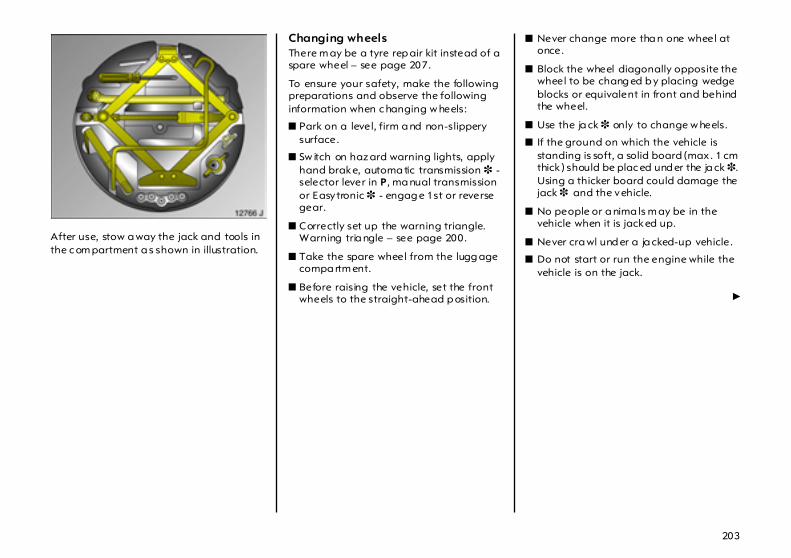
203
After use, stow a way the jack and tools in the c om partment a s shown in illustration.
Changing wheels There m ay be a tyre rep air kit instead of a spare wheel – see page 207.
To ensure your safety, make the following preparations and observe the following information when c hanging w heels:
z Park on a level, firm a nd non-slippery surface.
z Sw itch on haz ard warning lights, apply hand brake, automa tic transmission 3 - selector lever in P, ma nual transmission or Easytronic 3 - engag e 1st or reverse gear.
z Correctly set up the warning triangle. Warning tria ngle – see page 200.
z Take the spare wheel from the lugg age compa rtm ent.
z Before raising the vehicle, set the front wheels to the straight-ahead p osition.
z Never change more tha n one wheel at once.
z Block the wheel diagonally opposite the wheel to be chang ed b y placing wedge blocks or equivalent in front and behind the wheel.
z Use the ja ck 3 only to change w heels.
z If the ground on which the vehicle is standing is soft, a solid board (max. 1 cm thick ) should be plac ed und er the ja ck 3. Using a thicker board could damage the jack 3 and the vehicle.
z No people or a nima ls m ay be in the vehicle when it is jacked up.
z Never cra wl und er a ja cked-up vehicle.
z Do not start or run the engine while the vehicle is on the jack.
6
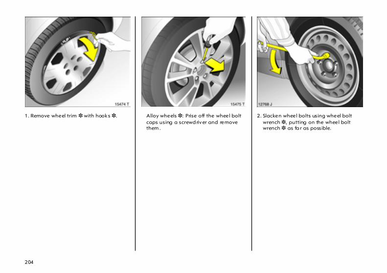
204
1. Remove wheel trim 3 with hooks 3. Alloy wheels 3: Prise off the wheel bolt caps using a screwd river and remove them .
2. Slacken wheel bolts using wheel bolt wrench 3, putting on the wheel bolt wrench 3 as fa r as possible.
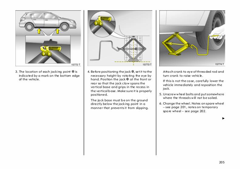
205
3. The location of each jack ing point 3 is indica ted by a mark on the bottom edge of the vehicle.
4. Before positioning the jack 3, set it to the necessary height by rota ting the eye by hand. Position the jack 3 at the front or rea r so that the jack c la w spans the vertical base and grips in the recess in the vertical b ase. Make sure it is properly positioned.
The ja ck base must b e on the ground directly below the jack ing point in a manner that prevents it from slipping.
Atta ch crank to eye of threa ded rod and turn crank to raise vehic le.
If this is not the ca se, carefully lower the vehicle immediately and reposition the jack.
5. Unscrew w heel bolts and put somewhere where the thread s w ill not b e soiled.
6. Change the wheel. Notes on spare wheel – see page 201, notes on temporary spa re wheel – see page 202.
6
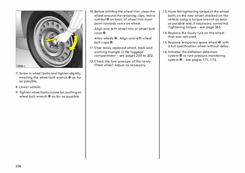
206
7. Screw in wheel bolts and tighten slig htly, inserting the wheel bolt wrench 3 as far as possible.
8. Lower vehicle.
9. Tighten wheel bolts crossw ise, putting on wheel bolt wrench 3 as fa r as possible.
10.Before refitting the w heel trim, clean the wheel around the retaining clips. Valve sym bol 3 on back of wheel trim must point towards va lve on wheel.
Align and refit wheel trim or wheel bolt ca ps 3.
Alloy wheels 3 : Align and refit w heel bolt c aps 3.
11.Stow away replaced wheel, tools and wa rning triangle in the luggage com partment – see pages 200 to 202.
12.Check the tyre pressure of the newly fitted wheel. Adjust as necessary.
13. Have the tightening torque of the wheel bolts on the new wheel checked on the vehicle using a torque wrench as soon as possib le and , if necessary, corrected. Tightening torque – see page 265.
14. Replace the faulty tyre on the wheel that was rem oved.
15. Replace temporary spare wheel 3 with a full specification wheel without delay .
16. Initialise the d eflation detection system 3 or tyre pressure monitoring system 3 – see pag es 171, 174.

207
Tyre repair kit 3 Minor damag e to the tyre tread or side wall, e.g. from foreign bodies, can be rep aired using the ty re repair kit.
Do not rem ove the foreign body from the tyre.
Tyre d amage exceeding 4 mm or that is on the rim cannot be repaired with the ty re rep air kit.
Imp ortant information – see page 210.
In the event of a flat tyre: z Switch on hazard wa rning lights, apply
hand brake, automatic transmission 3 - selector lever in P, manual transmission or Easytronic 3 - engage 1st or reverse gear.
z Correctly set up the w arning triangle. Warning triangle – see page 200.
The tyre repa ir kit is in a compartm ent in the spare wheel well of the lug gage compartment.
1. Take the pouch w ith the tyre repair k it from the compartment. Carefully remove the components from the pouch.
2. Remove the comp ressor.
3. Remove the electrical connection cable and air hose from the stowage compartments on the underside of the compressor.
Driv ing with inadequa te tyre pressure or a flat tyre can lea d to hidden tyre damage, which ca nnot be elim ina ted by using the ty re repair kit. Part the vehicle and consult a workshop. We recommend your Vauxhall Authorised Repairer.
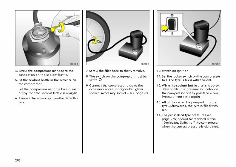
208
4. Screw the compressor air hose to the connection on the sealant bottle.
5. Fit the sealant bottle in the retainer on the compressor.
Set the compressor near the ty re in such a way tha t the sealant b ottle is up rig ht.
6. Remove the valve cap from the defective ty re.
7. Sc rew the filler hose to the ty re valve.
8. The switch on the compressor m ust be set to §.
9. Connec t the compressor plug to the accessory socket or cigarette lighter socket. Accessory socket – see page 83.
10. Switch on ignition.
11. Set the rocker switch on the com pressor to I. The tyre is filled with sea lant.
12. While the sealant bottle drains (a pprox. 30 seconds) the pressure ind icator on the com pressor briefly points to 6 b ar. Pressure then sinks a gain.
13. All of the sea la nt is pump ed into the tyre. Afterwards, the tyre is filled with air.
14. The presc rib ed tyre pressure (see page 265) should b e reached within 10 m inutes. Switch off the com pressor when the correct pressure is obtained.
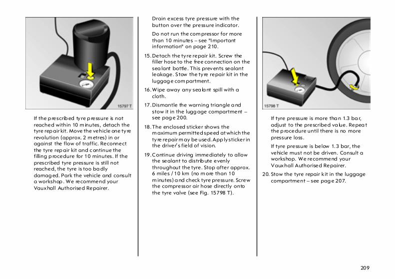
209
If the p rescrib ed tyre p ressure is not reached within 10 m inutes, detach the tyre rep air kit. Move the vehicle one ty re revolution (approx. 2 m etres) in or against the flow of traffic. Reconnect the tyre rep air kit and c ontinue the filling p rocedure for 10 minutes. If the prescribed tyre pressure is still not reached, the tyre is too ba dly damag ed. Park the vehicle and consult a workshop . We recommend your Vauxhall Authorised Repairer.
Drain excess tyre pressure with the button over the pressure indicator.
Do not run the com pressor for more than 10 minutes – see "Important information" on page 210.
15.Detach the ty re repair kit. Screw the filler hose to the free connection on the sea lant bottle. This prevents sealant leakage. S tow the ty re repair kit in the luggag e com partment.
16.Wipe away any sea la nt spill with a cloth.
17.Dismantle the warning triangle a nd stow it in the lugg age compartment – see pag e 200.
18.The enclosed sticker shows the m aximum permitted speed at which the ty re repair m ay be used. App ly sticker in the driver’s fie ld of vision.
19.Continue driving immediately to allow the sealant to distrib ute evenly throughout the tyre. Stop after approx. 6 miles / 10 km (no m ore than 10 m inutes) a nd check tyre pressure. Screw the compressor air hose directly onto the tyre valve (see Fig. 15798 T).
If tyre pressure is more tha n 1.3 ba r, adjust to the prescribed va lue. Repea t the p rocedure until there is no more pressure loss.
If tyre pressure is below 1.3 bar, the vehicle must not be driven. Consult a workshop. We recommend your Vauxhall Authorised Repairer.
20. Stow the tyre repair k it in the luggage compartment – see pag e 207.
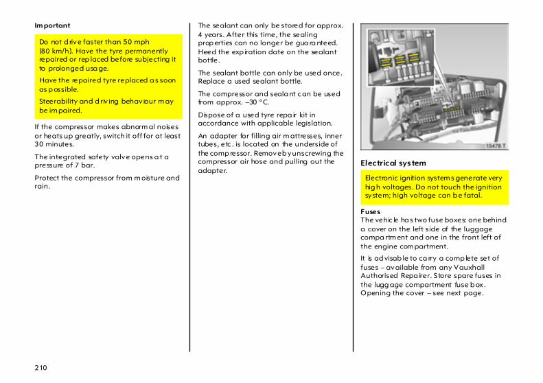
210
Im portant
If the compressor makes abnorm al noises or heats up greatly, switch it off for at least 30 minutes.
The integrated safety valve opens a t a pressure of 7 bar.
Protect the compressor from m oisture and rain.
The sealant can only be stored for approx. 4 years. After this time, the sealing prop erties can no longer be gua ra nteed. Heed the exp iration date on the sealant bottle.
The sealant bottle can only be used once. Replace a used sealant bottle.
The compressor and seala nt c an be used from approx. –30 °C.
Dispose of a used tyre repa ir kit in accordance with applicable legislation.
An adapter for filling air m attresses, inner tubes, etc . is located on the underside of the comp ressor. Remove b y unscrewing the compressor air hose and pulling out the adapter.
Electrical system
Fuses The vehic le ha s two fuse boxes: one behind a cover on the left side of the luggage compa rtm ent and one in the front left of the engine com partment.
It is ad visab le to ca rry a comp lete set of fuses – available from any Vauxhall Authorised Repa irer. S tore spare fuses in the lugg age compartment fuse b ox. Opening the cover – see next page.
Do not d rive faster than 50 mph(80 km/h). Have the tyre permanently repaired or rep laced before subjecting it to prolonged usa ge.
Have the repaired tyre replaced a s soon as p ossible.
Steerability and d riv ing behav iour m ay be im paired.
Electronic ignition system s generate very hig h voltages. Do not touch the ignition system; high voltage can b e fatal.

211
Before replac ing a fuse, turn off the respective switch and the ignition.
A defective fuse (Fig. 12892 J) can be recognised by its melted wire. A new fuse should only be installed after the c ause of the fault has been rectified.
There is a fuse extractor in the luggage compartment fuse box to fac ilitate fuse rep la cement – see above Fig.
Only fit fuses of the specified current rating. Each fuse has its c urrent ra ting written on it, in addition the ratings are colour coded.
Tw o different versions of fuses a re used.
Fuse Fusecolour rating
Brow nish yellow 5 ABrow n 7.5 A
Red 10 ABlue 15 A
Yellow 20 ATra nsparent 25 A
Green 30 A
Fuse Fuse
colour ratingBlue 20 A
Transp arent 25 APink 30 A
Green 40 A

212
Fuses and the most importantcircuits they protectFuse box in lugg age comp artmentThe fuse b ox is located behind a c over on the left sid e of the lug gage compartment. Use a coin to turn the locks as illustrated in the figure and fold the cover d ownwa rd .
Do not store any objects behind the cover.
Spa re fuses, fuse extra ctor – see page 210.
Some functions are protected by several fuses.
No. Circuit Rating
1 Elec tricwind ow s, front
25 A
2 – –
3 Instruments 7.5 A
4 Heating,air conditioning system,climate control system
5 A
5 Airba gs 7.5 A
6 – –
7 – –
8 – –
9 – –
No. Circui t Rat ing
10 – –
11 Heated rear window 25 A
12 Tailgate w iper 15 A
13 Parking dista nce sensor 5 A
14 Heating,air conditioning system
7.5
15 – –
16 Seat occupancy recognition 5 A
17 Rain sensor,air quality sensor,tyre pressure monitoring system,interior mirror
5 A
18 Instruments, switches 5 A

213
No. Circuit Rat ing
19 – –
20 CDC 10 A
21 Heated exterior mirrors1)
1) Not in co njunction w ith Vauxhall a larm system 3.
7.5 A
22 Sun roof 25 A
23 Elec tricwind ows, rear
25 A
24 Dia gnostics plug 7.5 A
25 – –
26 Elec trically retractableexterior mirrors
7.5 A
27 Ultrasonic sensor,Vauxhall ala rm system
5 A
No. Circuit Rating
28 – –
29 Cigarette lighter,front socket
15 A
30 – –
31 – –
32 – –
33 – –
34 Sun roof 25 A
35 – –
36 Towing equipment 20 A
37 Courtesy light 5 A
No. Circuit Rat ing
38 Central locking system,clam p 30
25 A
39 Seat heater (left) 15 A
40 Seat heater (right) 15 A
41 – –
42 – –
43 – –
44 – –
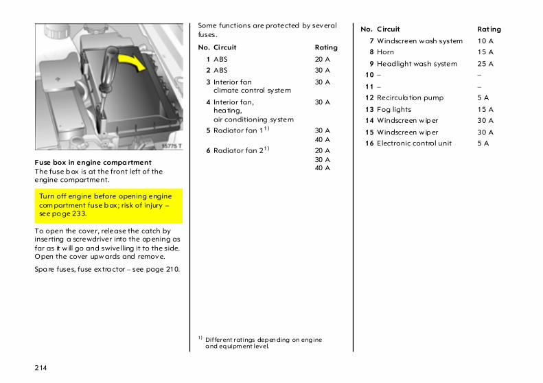
214
Fuse box in engine compa rtment The fuse b ox is at the front left of the engine compartment.
To open the cover, release the catch by inserting a screwdriver into the op ening as far as it w ill go and swivelling it to the side. Open the cover upw ards and remove.
Spa re fuses, fuse extra ctor – see page 210.
Some functions are protected by several fuses.
Turn off engine before opening engine com partment fuse b ox; risk of injury – see pa ge 233.
No. Ci rcuit Rating
1 ABS 20 A
2 ABS 30 A
3 Interior fanclimate control system
30 A
4 Interior fan,hea ting,air conditioning system
30 A
5 Radiator fan 11)
1) Different ratings depen ding on engine and equipm ent level.
30 A40 A
6 Radiator fan 21) 20 A30 A40 A
No. Circuit Rat ing
7 Windscreen w ash system 10 A
8 Horn 15 A
9 Headlight wash system 25 A
10 – –
11 – –
12 Recircula tion pump 5 A
13 Fog lights 15 A
14 Windscreen w ip er 30 A
15 Windscreen w ip er 30 A
16 Electronic control unit 5 A

215
No. Ci rcuit Rat ing
17 Diesel filter heating 25 A
18 Starter 25 A
19 Transm ission elec tronics 30 A
20 Air conditioning system 10 A
21 Engine electronics 20 A
22 Engine electronics 7.5 A
23 Adaptive Forward Lighting, head lig ht range adjustment
10 A
24 Fuel pump 15 A
25 Transm ission elec tronics 15 A
26 Engine electronics 10 A
No. Ci rcuit Rating
27 Power steering 5 A
28 Transm ission electronics 5 A
29 Transm ission electronics 7.5 A
30 Engine electronics 10 A
31 Adaptive Forward Lighting, hea dlight ra ng e adjustment
10 A
32 Brake system,air conditioning system
5 A
No. Circui t Rat ing
33 Adaptive Forward Lighting,headlight range adjustm ent
5 A
34 Control unitSteering column module
7.5 A
35 Infotainment system 20 A
36 Mobile telephone,digital radio,Twin Audio,displa y
7.5
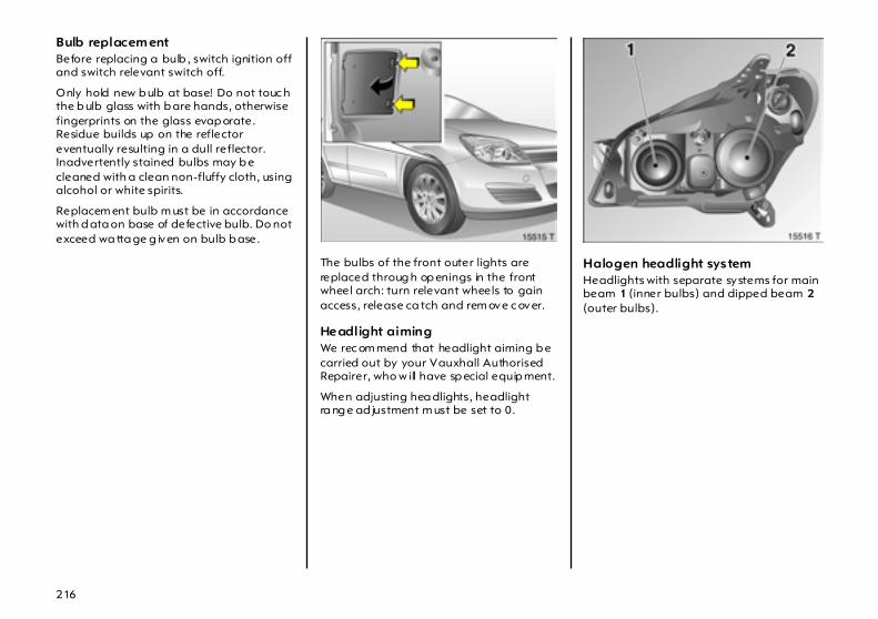
216
Bulb replacem ent Before replacing a bulb , switch ignition off and switch relevant switch off.
Only hold new b ulb at base! Do not touc h the b ulb glass with b are hands, otherwise fingerprints on the glass evap orate. Residue builds up on the reflector eventually resulting in a dull reflector. Inadvertently stained bulbs may b e cleaned with a clean non-fluffy cloth, using alcohol or white spirits.
Replacem ent bulb m ust be in accordance with d ata on base of defective bulb. Do not exceed wa tta ge g iven on bulb b ase.
The bulbs of the front outer lights are replaced throug h op enings in the front wheel arch: turn relevant wheels to gain access, release ca tch and rem ove c over.
Headlight aiming We rec om mend that headlight aiming b e carried out by your Vauxhall Authorised Repairer, who w ill have sp ecial equip ment.
When adjusting hea dlights, headlight ra ng e ad justment m ust be set to 0.
Halogen headlight system Headlights with separate systems for main beam 1 (inner bulbs) and dipped beam 2 (outer bulbs).
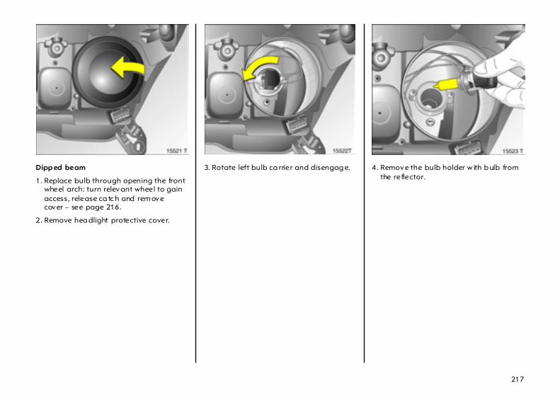
217
Dipp ed beam
1. Replace bulb through opening the front wheel arch: turn relevant wheel to gain access, release ca tc h and rem ove cover – see page 216.
2. Remove hea dlight protective cover.
3. Rotate left bulb ca rrier and disengag e. 4. Remove the bulb holder w ith b ulb from the reflector.

218
5. Detach b ulb from bulb mounting.
6. Insert new bulb into bulb mounting, without touching the gla ss.
7. Insert new bulb so that the two lugs on the bulb m ounting eng age in the recesses in the reflector.
8. Rotate b ulb carrier to right as far as it will go.
9. Place headlight protective cover in position and close.
10. Position cover on opening in wheel arch and enga ge.
Main beam
1. Open bonnet.
2. Replace bulbs from engine compa rtm ent out.
To rep lace the bulb on the rig ht-hand side, remove the air hose from the air filter.
To rep lace the bulb on the left-ha nd side, remove the plug from the fuse box.
3. Remove headlight protective c over.
4. Deta ch plug connector from bulb.
5. Disengage sp ring clip from retainer by pressing forwa rd and then swing downward.
6. Remove bulb from reflector housing.
7. When fitting a new bulb, eng age the lugs in the rec esses on the reflector without touching the g lass.

219
8. Engage spring wire clip, plug connector onto b ulb.
9. Place headlight protective cover in position and close.
After bulb replacem ent on the right-hand side, reattach air hose to a ir filter and enga ge.
After bulb replacem ent on the left-hand sid e, reconnect plug to fuse b ox and enga ge.
Pa rking lights
1. Open bonnet.
2. Replace bulbs from engine compa rtm ent out.
To rep lace the bulb on the rig ht-hand side, remove the air hose from the air filter.
To rep lace the bulb on the left-ha nd side, remove the plug from the fuse box.
3. Remove main beam head lig ht protective cover.
4. Remove pa rk ing light bulb holder from reflector.
6
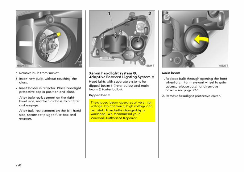
220
5. Remove bulb from socket.
6. Insert new bulb, without touching the glass.
7. Insert holder in reflector. Place headlight protective cap in position and close.
After bulb rep la cement on the right-hand side, reattach air hose to air filter and engage.
After bulb replacement on the left-ha nd side, reconnect plug to fuse box and engage.
Xenon headlight system 3,Adaptive Forw ard Lighting System 3 Head lig hts with separate systems for dipped bea m 1 (inner bulbs) a nd main beam 2 (outer bulbs).
Dipped beam
Ma in beam
1. Replac e bulb through opening the front wheel arch: turn relevant wheel to gain access, release c atch and rem ove cover – see page 216.
2. Remove headlight protective cover.
The d ipped beam operates a t very high voltage. Do not touch; high voltage c an be fatal. H ave bulbs cha nged by a workshop . We recommend your Vauxhall Authorised R epairer.
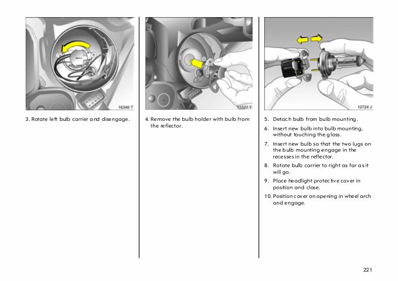
221
3. Rotate left bulb carrier a nd disengage. 4. Remove the bulb holder with bulb from the reflector.
5. Detac h bulb from bulb mounting .
6. Insert new bulb into bulb mounting, without touching the g lass.
7. Insert new bulb so that the two lugs on the b ulb mounting engage in the recesses in the reflector.
8. Rotate bulb carrier to right as far a s it will go.
9. Place headlight protec tive cover in position and close.
10. Position c over on opening in wheel arch and engage.
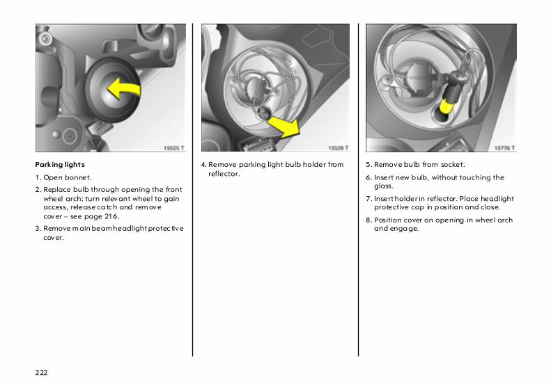
222
Parking lights
1. Open bonnet.
2. Replace bulb through opening the front wheel arch: turn relevant wheel to gain access, release ca tc h and rem ove cover – see page 216.
3. Remove m ain beam headlight protec tive cover.
4. Remove parking light bulb holder from reflector.
5. Remove bulb from socket.
6. Insert new b ulb, without touching the glass.
7. Insert holder in reflector. Place headlight protective cap in p osition and close.
8. Position cover on opening in wheel arch and enga ge.
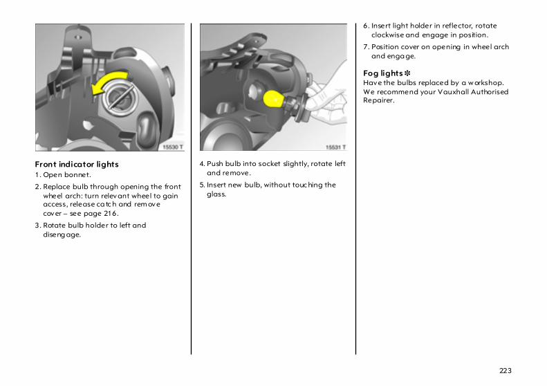
223
Front indicator lights 1. Open bonnet.
2. Replace bulb through opening the front wheel arch: turn relevant wheel to gain access, release ca tc h and rem ove cover – see page 216.
3. Rotate bulb holder to left and diseng age.
4. Push bulb into socket slightly, rotate left and remove.
5. Insert new bulb, without touc hing the glass.
6. Insert light holder in reflector, rotate clockwise and engage in position.
7. Position cover on opening in wheel arch and enga ge.
Fog lights 3 Have the bulbs replaced by a w orkshop. We recommend your Vauxhall Authorised Repairer.

224
Turn signals , brake, tail,fog tail, revers ing lights Hatch1. To replace bulbs on the right side, use a
coin to open the lock as indica ted in the Fig. and fold the cover down.
To replace bulbs on the left side, use a coin to turn both locks as illustrated on page 212 in Fig. 15476 T and fold the cover d own.
2. Deta ch plug connector from bulb mounting .
3. Hold outside of b ulb housing, loosen fastening nuts with wheel bolt w rench 3 and unscrew b y hand. Wheel bolt wrench 3 – see vehicle tools on page 202.
4. Detach bulb housing tow ards the rea r.

225
5. Unscrew three screws using a screw driver (vehicle tools – see pa ge 202). Press lock ing tabs on outside of bulb hold er out and remove the bulb hold er.
Bulbs in bulb mounting: 1 = R eversing light 2 = Turn signa l 3 = Tail lig ht/brake light 4 = Tail lig ht 5 = Fog tail light
6. Remove bulb from socket.
7. Insert new b ulb; do not touch the glass. Engage bulb m ounting in bulb housing. Insert bulb housing into body and tighten fastening nuts by hand . C lose and lock cover.
8. To ensure proper tail light function:
– Switc h on ig nition
– Operate brake
– Switc h on parking lights

226
Estate1. Disenga ge c over by pressing retaining
lugs and remove.
2. Deta ch plug connector from bulb mounting .
3. Hold the outside of the bulb housing, unscrew the three fastening nuts and rem ove the bulb housing rearwards.
4. Unscrew the three screws with a screwdriver (vehicle tools – see page 202) and remove the bulb mounting.

227
Bulbs in bulb m ounting: 1 = Tail light/brake light 2 = Turn signal 3 = Reversing light 4 = Fog tail light
5. Remove bulb from socket.
6. Insert new bulb without touching the glass. Insert bulb m ounting in bulb housing and screw in place. Insert bulb housing into body and tighten fa stening nuts b y hand. Attach p lug connector. C lose and lock cover.
7. To ensure p roper tail light function:
– Switch on ignition
– Operate b ra ke
– Switch on parking lights
Number plate light 1. Insert screw driver vertically in b ulb insert
as illustrated in figure. Press to the side and release spring.
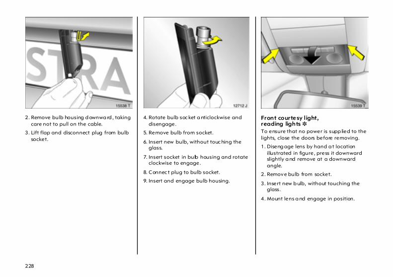
228
2. Remove bulb housing d ownwa rd , taking care not to pull on the cable.
3. Lift flap and disconnect plug from bulb socket.
4. Rotate bulb soc ket a nticlockwise and disengage.
5. Remove bulb from socket.
6. Insert new bulb, without touc hing the glass.
7. Insert socket in bulb housing and rotate clockwise to engage.
8. Connec t plug to bulb socket.
9. Insert and engage bulb housing.
Front courtesy light,reading lights 3 To ensure that no power is supp lied to the lights, close the doors before removing.
1. Diseng age lens by hand a t location illustrated in figure, press it downward slightly a nd remove at a downward angle.
2. Remove bulb from socket.
3. Insert new b ulb, without touching the glass.
4. Mount lens a nd engage in position.
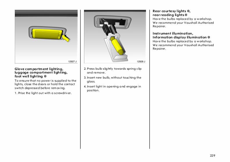
229
Glove com partm ent lighting,luggage compartment lighting,foot well lighting 3 To ensure that no power is supplied to the lights, close the d oors or hold the contact switch depressed before rem ov ing.
1. Prise the light out with a screwdriver.
2. Press bulb slig htly towards spring c lip and remove.
3. Insert new bulb, without touc hing the glass.
4. Insert light in opening a nd engage in position.
Rear courtesy lights 3,rear reading lights 3 Have the bulbs replaced by a w orkshop. We recommend your Vauxhall Authorised Repairer.
Instrument il lumination,Information display illumination 3 Have the bulbs replaced by a w orkshop. We recommend your Vauxhall Authorised Repairer.

230
If you have a problem
In our experience the m ost comm on ca use of all comp la ints is the result of misundersta nding or la ck of communication between the customer and the Vauxhall Authorised Rep airer.
We sincerely hope you will never have cause to c om plain about your vehicle. However, if things do g o wrong, the b est course of action for you to take is to contact your Vauxhall Authorised Repairer’s Service Rec eption Staff and explain the d ifficulty you are having. We are confident they will do their utmost to resolve the problem to your comp lete satisfaction.
Sometimes, however, despite the b est of intentions of all c oncerned, misundersta ndings can occur. If your problem has not been resolved to your satisfaction, please make an app ointment to discuss the matter with the Manager of
the department c oncerned.
The majority of areas of concern can be quic kly resolved in this way.
Should you wish to pursue the matter further, the Principal of the Vauxhall Authorised Repairer should be made aware of your concern. It is ad visab le in cases such as this to write to him to confirm your problem and the solutions that have been offered.
You can be assured the Authorised Repairer’s Principal w ill only be too anxious to fully investigate your prob lems and correct any errors m ade. After a ll, he has a large investm ent in his business and is proud of his reputation and professionalism and fully realises that satisfied c ustomers are his key to success.
In the unlikely event that you are still not ha ppy with the answer your Vauxhall Authorised Repairer has given, or the action he prop oses to correct the problem, you may conta ct the Customer Care Department1) w here a team of Custom er Care Consultants will spare no effort to ensure your complete satisfa ction.
Va uxhall Motors Ltd.Customer Ca re,Griffin House,Osborne Road, LUTON, Beds., LU1 3YTTelep hone: 01582 427200
They w ill review all the facts involved. Then if it is felt some further action can be taken, the Vauxhall Authorised Repairer will b e adv ised accordingly. In any case, your contact will b e ac knowledged confirm ing Vauxhall Motors’ position in the m atter.
If you are not satisfied with the outcome, you ca n if you wish, seek advice from an independent third p arty suc h as:
Autom obile Association (A.A. )Fanum House, BASINGSTOKE,Hants., R G21 2EA
Royal Autom obile Club (R.A.C.),R.A.C. M otoring Services Ltd.,89-91 Pall Mall,LONDON, SW1Y S45
The Customer Relations Dep artment,Soc iety of Motor Manufactur ers and Trad ers Ltd. (S .M.M.T.),Forbes House, H alkin Street, LONDON, SW1X 7DS
Customer Complaints Service,Sc ottish Motor Tra de Association, (S.M.T.A.),3 Palmerston Place,EDINBURGH, EH 12 5AQ
The National Conciliation Serv ice,Retai l Motor Indust ry Federation,9 North Street, RUGBY, CV21 2AB
I f you have a problem w hilst ab road:The Service Departm ents of Adam Op el AG and General M otors branches everywhere will provid e information and assistance:
1) Calls may be mo nito red and recorded fo r tra in in g purposes.
231
In Alb ania, Bosnia-H erzegovina ,Bulga ria, Croatia, Macedonia,Roma nia and Slovenia please contact the OpelService Department in Budaörs – HungaryTel. 00 36-23 446 100
General Motors Austria Vertriebs GmbHGroß-Enzersdorfer S tr. 59 1220 Vienna – AustriaTel. 00 43 1-2 88 77 444 or00 43-1-2 88 77 0
General Motors B elgium N .V.Prins Boudewijnlaa n 30 2550 Kontich – Belgium Tel. 00 32-34 50 63 11
Opel C & S spol. s. r.o.Na Pank ráci 26 140 00 Pra gue 4 – Czech R epub lic Tel. 00 420-2-61 21-88 21
General Motors Da nm arkJaegersborg Alle 4 2920 Charlot tenlund – Denmark Tel. 00 45-39 97 85 00
ADAM OPEL AGBahnhofsplatz 1 65423 Rüsselsheim – Germany Tel. 00 49-61 42-77 50 00 or00 49-61 42-7 70
Vauxhall Motors Ltd.Customer CareGriffin H ouse, Osborne Road Luton, Bedfordshire, LU1 3YT – Eng land Tel. 00 44-15 82-42 72 00
General Motors Finland OyPa juniityntie 5 00320 Helsinki – Finland Tel. H elsink i 00 358-9 817 101 47
General Motors Franc e1 – 9, avenue du M araisAngle Qua i de Bezons 95101 Argenteuil Cedex – France Tel. 00 33-1-34 26 30 51
General Motors Hellas S.A.56 Kifisias Avenue & Delfon str.Am arousion 151 25 Athens – Greece Tel. 00 30-1-6 80 65 01
Opel Southeast Europe Ltd .Szabad sag utc a 117 2040 Buda örs – Hungary Tel. 00 36-23 446 100
General Motors IndiaSixth Floor, Tow er AGlob al Business ParkMehrauli – Gurgaon Road Gurgaon – 122 022, Harya na – Ind ia Tel. 00 91-124 280 3333
Opel Irela nd Ltd.Opel House, Unit 60, Heather Road Sandyford, Dublin 18 – I reland Tel. 00 353 1-216 10 00
General Motors Italia S rlPiaz zale dell’Industria 40 00144 Rome – Italy Tel. 00 39-6-5 46 51
General Motors Ned erland B.V.Lage Mosten 49 – 63 4822 NK Breda – N etherla nds Tel. 00 31-76-5 44 88 00
General Motors Norge ASKjeller-Vest 6 2027 Kjel ler – Norw ay Tel. 00 47-23 50 01 04
General Motors Poland Sp. z o. o.Domaniewska 41 06- 672 Wa rsa w – Pola nd Tel. 00 48-22-606 17 00
General Motors PortugalQuinta da FonteEdific ío Fernão Magalhães, Piso 2 2780-190 Paço d’Arcos – Portugal Tel. 00 351-21 440 75 00
General Motors Norden ABÅrsta ängvägen 17 100 73 Stockholm – S weden Tel. 00 46-20 333 000
General Motors Suisse S.A.Stelzenstraße 4 8152 Glattbrugg – Swi tzerla nd Tel. 00 41-44 828 28 80
General Motors España S.L.Paseo de la Castellana, 91 28046 Madrid – Sp ain Tel. 00 34-902 25 00 25
Opel Türkiye Ltd. S ti.Kemalp asa yolu üzeri 35861 Torb ali/Izmir – Turkey Tel. 00 90-2 32-8 53-14 53
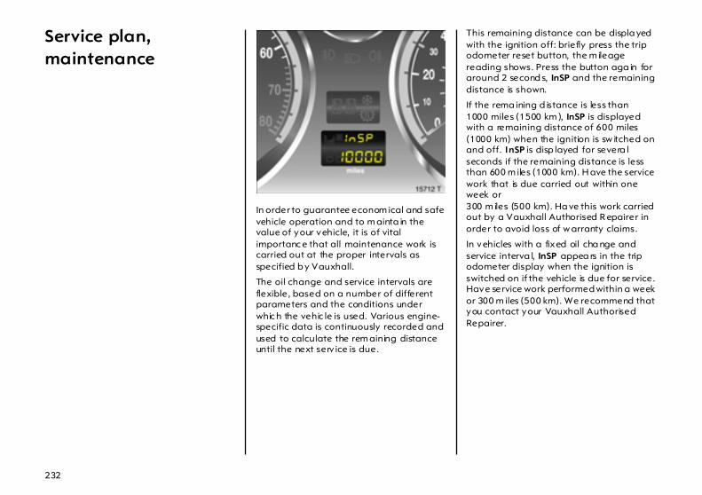
232
Service plan, maintenance
In order to guarantee econom ical and safe vehicle operation and to m ainta in the value of your vehicle, it is of vital importanc e that all maintenance work is carried out at the proper intervals as specified b y Vauxhall.
The oil change and service intervals are flexible, based on a number of different parameters and the conditions under whic h the vehic le is used. Various engine-specific data is continuously recorded and used to calculate the rem aining distance until the next serv ice is due.
This remaining distance can be displa yed with the ignition off: briefly press the trip odometer reset button, the m ileage reading shows. Press the button aga in for around 2 second s, InSP and the remaining distance is shown.
If the rema ining d istance is less than 1000 miles (1500 km ), InSP is displayed with a remaining distance of 600 miles (1000 km) when the ignition is sw itched on and off. InSP is disp layed for severa l seconds if the remaining distance is less than 600 m iles (1000 km). H ave the service work that is due carried out within one week or 300 m iles (500 km). Ha ve this work carried out by a Vauxhall Authorised R epairer in order to avoid loss of w arranty claims.
In vehicles with a fixed oil cha nge and service interva l, InSP appea rs in the trip odometer display when the ignition is switched on if the vehicle is due for service. Have service work performed within a week or 300 m iles (500 km). We recommend that you contact your Vauxhall Authorised Repairer.

233
The serv ice interval display takes account of off-the-road periods during which the battery is disconnected.
Further information on maintenance and the inspec tion system can be found in the service booklet, which is in the glove compartment.
Have maintenance work, as well as repairs to the b od ywork and equipment, carried out by a professional. We recom mend your Vauxhall Authorised Repairer, who is familiar with Vauxhall vehicles and in possession of the nec essary sp ecial tools and the latest service instructions from Vauxhall. It is particularly advisable to use a Vauxhall Authorised Repairer during the warranty p eriod to avoid invalidation of warranty claims. See the Serv ice Booklet for further information.
Separ ate anti-cor rosion service Have this carried out every 2 years, either within the scope of an a nnual inspection or separately, see serv ice b ooklet. We recom mend tha t you consult your Vauxhall Authorised Repairer in order to avoid loss of warranty cla im s for rust damag e.
A note on safety To avoid injury from cables cond ucting ignition voltage and m ov ing parts, only carry out engine compartment checks (e.g. checking brake fluid or engine oil level) when the ignition is switched off.
Never carry out any repairs or adjustment and m aintenance work on the vehicle yourself. This especially applies to the eng ine, chassis and safety parts. You may unwittingly infringe the p rov isions of the law and, by not performing the work properly , endanger yourself and other road users.
Checking and topping up fluids To aid identification, the cap s used when topping up engine oil, coolant and wash fluid as w ell as the oil d ip stick are coloured yellow.
The cooling fan is controlled by a thermoswitch and ca n therefore start unexp ectedly even if the ignition is switched off. Risk of injury.
Electronic ignition systems generate very high voltages. Do not touch the ignition system; hig h voltage can be fatal.
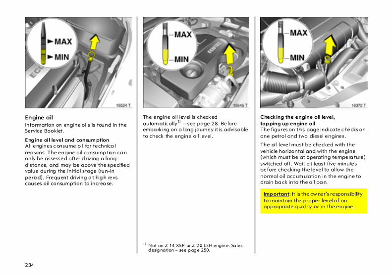
234
Engine oil Information on engine oils is found in the Service Booklet.
Eng ine oi l level and consum ptionAll engines c onsume oil for technica l rea sons. The engine oil consump tion ca n only be assessed after d riv ing a long distance, and may be above the specified value during the initial stage (run-in period). Frequent driving a t hig h revs causes oil consumption to increa se.
The engine oil level is checked autom atic ally1) – see page 28. Before emba rk ing on a long journey it is advisable to check the engine oil level.
Checking the engine oil level,top ping up engine oilThe figures on this page indicate c hecks on one petrol and two diesel engines.
The oil level must be checked with the vehicle horizontal and with the engine (which must be at operating tempera ture) switched off. Wait a t least five minutes before checking the level to allow the normal oil acc um ulation in the engine to drain ba ck into the oil pa n.
1) Not on Z 14 XEP or Z 2 0 LEH engin e. Sa les designation – see page 250.
Imp ortant: It is the ow ner’s responsibility to maintain the proper level of an appropriate qua lity oil in the engine.

235
To check oil level, wip e off the dipstick and insert it up to the stop mark on the handle. Top up oil if the level has fallen to the MIN mark.
The oil level must not go above the upper mark MAX on the dipstick. Excess oil m ust be drained or extracted b y suction. If the oil level does go above the mark MAX there is a risk of d amage to the engine or catalytic converter.
Ca pacity between MIN and MAX m arks – see pages 272, 273.
When top ping up, use the sam e b ra nd of oil that was used during the previous oil cha ng e. Observe the information in the Serv ic e Booklet.
To close, position the cap and screw it into place.
Capacities – see pages 272, 273.
Oil chang e, oi l filter cha ng e Cha nge the oil at the displayed serv ice interva ls.
We recommend that you use g enuine Vauxhall oil filters.
Used oil filters and empty oil containers should not be disp osed of as domestic refuse. We recomm end that you entrust oil and oil filter changes to a Va uxha ll Authorised Repa irer, who is familiar with legal requirem ents reg arding disposa l of used oil and can thus help to p rotect both the env ironment and your hea lth.
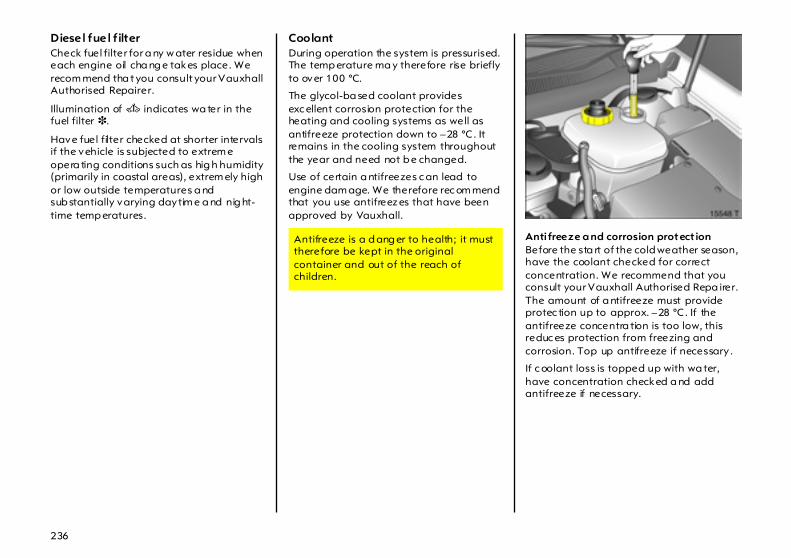
236
Diesel fuel f ilter Check fuel filter for a ny w ater residue when each engine oil cha ng e takes place. We recom mend tha t you consult your Vauxhall Authorised Repairer.
Illumination of A indicates wa ter in the fuel filter 3.
Have fuel filter checked at shorter intervals if the vehicle is subjected to extrem e opera ting conditions such as hig h humidity (primarily in coastal areas), extrem ely high or low outside temperatures a nd sub stantially varying daytim e a nd nig ht-time temp eratures.
Coolant During operation the system is pressurised. The temp erature ma y therefore rise briefly to over 100 °C.
The glycol-ba sed coolant provides exc ellent corrosion protection for the heating and cooling systems as well as antifreeze protection down to –28 °C. It remains in the cooling system throughout the year and need not b e changed.
Use of certain a ntifreezes c an lead to engine dam age. We therefore rec om mend that you use antifreez es that have been approved by Vauxhall.
Anti freeze a nd corrosion protect ionBefore the sta rt of the cold weather season, have the coolant checked for correct concentration. We recommend that you consult your Vauxhall Authorised Repa irer. The amount of a ntifreeze must provide protec tion up to approx. –28 °C. If the antifreeze concentra tion is too low, this reduc es protection from freezing and corrosion. Top up antifreeze if necessary .
If c oolant loss is topped up with wa ter, have concentration checked a nd add antifreeze if necessary.
Antifreeze is a d ang er to health; it must therefore be kept in the original container and out of the reach of children.
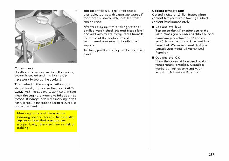
237
Coola nt level Hardly any losses occur since the cooling system is sealed and it is thus rarely necessary to top up the c oolant.
The c oolant in the compensation tank should b e slightly above the mark KALT/COLD with the cooling system cold. It rises when the engine is w arm a nd falls ag ain as it cools. If it drops below the marking in this case, it should be topped up to a level just above the marking.
Top up antifreez e. I f no antifreeze is available, top up w ith c lean tap water. If tap water is unavailable, distilled water can be used.
After topping up with drinking water or distilled water, check the anti-freeze level and add anti-freeze if required. E lim ina te the cause of the coolant loss. We recommend your Vauxhall Authorised Repairer.
To close, position the cap and screw it into place.
Coolant temp era ture Control indicator W illuminates when coolant tem perature is too high. Check coolant level im mediately:
z Coolant level low:Top up coolant. Pay attention to the instructions given under "Antifreeze and corrosion protection" and "Coolant level". Have the cause of coolant loss remedied . We recommend that you consult your Vauxhall Authorised Repairer.
z Coolant level OK:Have the c ause of inc reased coolant temperature remed ied. Consult a workshop. We rec om mend your Vauxhall Authorised Repairer.
Allow engine to cool d ow n before removing coola nt filler ca p. Remove filler cap carefully so that p ressure can escape slowly, otherwise there is a risk of scalding.

238
Brake fluid Brake fluid level
The fluid level in the reservoir must b e neither higher than the MAX ma rk nor lower than the MIN mark.
Use of certain brake fluid s c an lead to dam age or reduced braking effect. We therefore recomm end that you use only high performance brake fluid a pproved by Vauxhall.
When top ping up, ensure m aximum cleanliness as contam ination of the brake fluid c an lead to function problem s in the braking system.
After correcting the brake fluid level, have the cause of brake fluid loss remedied . We recommend that you consult your Vauxhall Authorised Repairer.
Brake fluid cha ng e Brake fluid is hygrosc op ic , i.e. it ab sorbs water. If the brakes become hot, such as when driving on long downhill stretches, va pour b ub bles can occur in the water, which can have an extremely adverse effect on braking power (dep ending on the proportion of water).
The fluid c hange interva ls specified in the Service Booklet m ust therefore be observed.
Caution – brake fluid is poisonous and corrosive. Do not allow it to come into contact with eyes, sk in, fabric or painted surfaces. Direct contact could cause injury and damage.
We recom mend that you have brake fluid c hanged by a Vauxhall Authorised Repairer, who will b e familiar w ith the requirem ents of the law a s regards disposal of brake fluid and can thus help to protect the environment a nd your health.

239
Windscreen wiper Clear vision is essential for safe driving.
Perform regular checks on the windscreen wiper and hea dlight wash system 3 to ensure they are operating correctly. We recom mend wiper bla de replacement at lea st once a year.
If the windscreen is dirty, operate the windscreen wash system before sw itc hing on the windscreen wiper or setting the wiper to automa tic op eration with the rain sensor 3. This will a void wiper blade wear.
Do not switc h on the windscreen wiper or set them to automatic operation w ith the rain sensor 3 if the windscreen is iced up as this could da mage the wiper blades or the wiper system.
If the wiper b ecome froz en on to the glass, we recommend that they be relea sed with the aid of Vauxhall De-icer Spray.
Smearing wiper blades can be c leaned with a soft c loth and Vauxhall Windscreen Wash Solvent.
Wiper blades whose lips ha ve become ha rd ened, cracked or covered with silicone must b e replaced . This may b e necessa ry as a result of the effects of ice, thawing sa lt or heat, or the incorrect use of cleaning agents.
Switch off the windscreen wiper or autom atic wiper with rain sensor 3 in car washes – see pages 17, 18, 245.
Windscreen wiper care – see page 247. To ensure p roper operation of the rain sensor 3, the sensor area must be free from dust, dirt and ic e. The windscreen wash system must a lso be opera ted at regular interva ls and the sensor area m ust be de-iced. Vehicles w ith ra in sensor 3 c an be identified by the sensor area near the top of the wind screen.
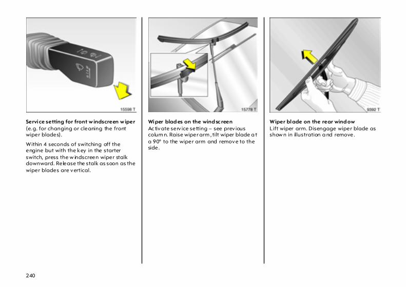
240
Service setting for front w indscreen w iper (e.g. for changing or cleaning the front wiper blades).
Within 4 seconds of switching off the engine but with the key in the starter switch, press the w indscreen wiper stalk downward. Release the stalk as soon as the wiper blades are vertical.
Wiper blad es on the wind sc reen Ac tivate serv ice setting – see prev ious colum n. Raise wiper arm , tilt wiper blade a t a 90° to the wiper arm and remove to the side.
Wiper blade on the rear wind ow Lift wiper arm. Disengage wiper blade as show n in illustration a nd remove.

241
Windscreen and headlight wash systems 3 The fluid reservoir filler neck for the windscreen wash system and headlight wash system 3 is loca ted a t the front next to the left headlight .
Ca pacities – see p ages 272, 273.
Fill only with clean w ater to prevent the nozzles from clogging. To improve cleaning efficiency, we recommend that you add a little Vauxhall Wind screen Wash Solvent.
The windscreen wash system and headlight wa sh system will not freez e in winter:
When closing the reservoir, p ress the lid firmly over the beaded ed ge a ll the way round.
Frost protection down to
MixtureVauxhall
Windscreen Wash Solvent : Water
– 5 °C 1 : 3
– 10 °C 1 : 2
– 20 °C 1 : 1
– 30 °C 2 : 1
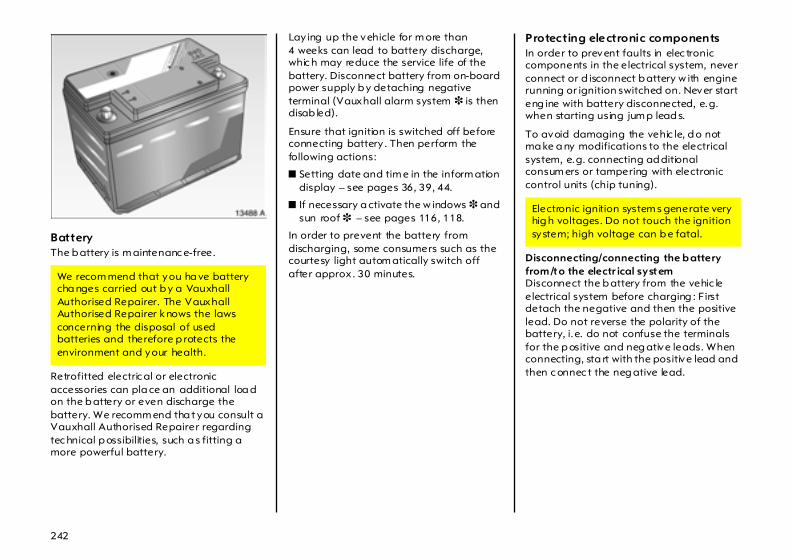
242
Battery The b attery is m aintenanc e-free.
Retrofitted electric al or electronic accessories can pla ce an additional loa d on the b attery or even discharge the battery. We recomm end tha t you consult a Vauxhall Authorised Repairer regarding tec hnical p ossibilities, such a s fitting a more powerful battery.
Lay ing up the vehicle for m ore than 4 weeks can lead to battery discharge, whic h may reduce the service life of the battery. Disconnect battery from on-board power supply b y detaching negative terminal (Vauxhall alarm system 3 is then disab led).
Ensure that ignition is switched off before connecting battery . Then perform the following actions:
z Setting date and tim e in the inform ation display – see pages 36, 39, 44.
z If necessary a ctivate the w indows 3 and sun roof 3 – see pages 116, 118.
In order to prevent the battery from discharging, some consumers such as the courtesy light autom atically switch off after approx . 30 minutes.
Protecting electronic components In order to prevent faults in elec tronic components in the electrical system, never connect or d isconnect b attery w ith engine running or ignition switched on. Never start eng ine with battery disconnected, e.g. when starting using jum p lead s.
To avoid damaging the vehic le, d o not ma ke a ny modifications to the electrical system, e.g. connecting ad ditional consum ers or tampering with electronic control units (chip tuning).
Disconnecting/connecting the b attery from /to the electr ical system Disconnect the b attery from the vehic le electrical system before charging : First detach the negative and then the positive lead. Do not reverse the polarity of the battery, i.e. do not confuse the terminals for the p ositive and neg ative leads. When connecting, sta rt with the positive lead and then c onnec t the neg ative lead.
We recom mend that you ha ve battery cha nges carried out b y a Vauxhall Authorised Repairer. The Vauxhall Authorised Repairer knows the laws concerning the disposal of used batteries and therefore p rotects the environment and your health.
Electronic ignition system s generate very hig h voltages. Do not touch the ignition system; high voltage can b e fatal.

243
Vehicle decom missioning Observe na tional regulations.
If the vehicle is decomm issioned for several months, the follow ing work must be ca rried out in order to prevent damage. We recom mend tha t you consult your Vauxhall Authorised Repairer.
z Wash and preserve the vehicle – see page 245.
z Check preservation in engine com partment a nd on underbody a nd rectify where necessary .
z Clean and preserve rubber seals on bonnet and doors.
z Change engine oil – see page 235.
z Check antifreeze and c orrosion protection – see page 236.
z Check the coolant level, top up with antifreeze if necessary – see page 237.
z Empty windsc reen w ash system and headlight wa sh system.
z Inc rease ty re pressure to value sp ecified for full load – see page 266.
Vehicle storag e z Park vehicle in dry, w ell ventila ted
place. With manual transmission or Easytronic 3 , enga ge 1st or reverse gear. With automatic transm ission 3, selector lever in P. Use chocks or the like to prevent the vehicle from rolling .
z Do not apply hand brake.
z Disconnect battery by disengaging neg ative terminal from vehicle electrical system – see page 242.
Vehicle recomm issioningObserve national regulations.
Perform the following work before recommissioning the vehicle:
z Connect ba ttery – see page 242.
z Check tyre pressure and correc t if necessary – see page 266.
z Fill up w indscreen wash system – see page 241.
z Check engine oil level – see p age 234.
z Check the coolant level; top up with antifreeze if necessary – see page 237.
z Fit the num ber p la te if necessary .
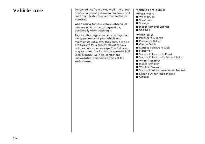
244
Vehicle care Obtain adv ice from a Vauxhall Authorised Repairer regarding cleaning materials tha t ha ve b een tested a nd recomm ended by Vauxhall.
When caring for your vehicle, observe all na tional environm ental reg ulations, particula rly when wa shing it.
Regular, thorough care helps to improve the appearance of your vehicle and maintain its value over the years. It is a lso prereq uisite for w arra nty claims for any paint or corrosion damag e. The following pages contain tips for vehicle care which, if used properly , will help combat the unavoida ble, damaging effects of the environment.
Vehicle care aids 3 Vehicle wash: z Wa sh brush z Shampoo z Sponge z Insect Removal Sponge z Chamois
Vehicle care: z Paintwork Clea ner z Paintwork Polish z Crea m Polish z Metallic Paintwork Wax z Hard wa x z Vauxhall Touch-Up Paint z Vauxhall Touch-Up/Aerosol Paint z Wheel Preserver z Insect Remover z Window Cleaner z Vauxhall Windscreen Wa sh Solvent z Silicone Oil for Rubber Sea ls z Cleaner
245
Washing The paintwork of your vehicle is exposed to env ironmenta l influences, e.g. continuous changes in weather conditions, ind ustrial waste gases and dust or tha wing sa lts, so wash and wax your vehicle regularly. When using a utoma tic car washes, select a programme which includes wax ing.
Bird droppings, dead insects, resin, pollen and the like should be cleaned off immediately , as they contain aggressive constituents which can cause paint dam age.
If using a car w ash, comply w ith the pertinent instructions of the ca r wash manufacturer. The windsc reen w iper and rea r window wiper must be switched off – see pag es 17, 18. Remove aerial 3 and roof rack 3. S ta nd on the d oor sill to reach them more easily.
If you w ash your vehicle by hand, make sure that the insides of the wing s a re also thoroughly rinsed out.
Clea n edges and folds on op ened doors and flaps as well a s the area s they cover.
Thoroughly rinse off and leather-off the vehicle. Rinse leather frequently . Use separate leathers for paint and w indow surfaces: remnants of wax on the wind ow s will impair vision.
Observe national regulations.
Waxing Wax your vehicle regularly, in pa rticular after it has been washed using shampoo and at the latest when wa ter no longer forms beads on the pa intwork, otherwise the paintwork will d ry out.
Also wax edg es a nd folds on op ened doors and flaps as well a s the area s they cover.
Polishing Polishing is necessary only if the pa int has become dull or if solid deposits have become attached to it.
Paintwork polish with silicone forms a protec tive film, making w axing unnecessary.
Plastic body parts should not be treated with wax and polish.
Use Metallic Paintwork Wax on vehicles with a metallic-effect paint finish.
Wheels Use a pH-neutral w heel c leaning agent to clean the wheels.
Wheels a re painted and ca n be treated with the same ag ents as the body. For alloy wheels we recomm end use of Alloy Wheel Preserver.
246
Paintwork damage Repair small area s of p aint damage suc h as stone impacts, scratches etc. immediately using a Va uxha ll touch-up applicator or Vauxhall sp ra y and touch-up paint before rust can form . If rust has alrea dy formed, ha ve the c ause remedied. We recommend that you consult your Vauxhall Authorised Repairer. Please also pay attention to surfaces and edg es beneath the vehicle where which rust ma y have form ed unnoticed for some time.
Exterior lights Headlight and other protective lig ht bezels are made of plastic. If they require additional cleaning after the vehicle has been washed, clea n them with Car Shamp oo. Do not use any ab ra sive or caustic agents, do not use an ice scraper, and do not clean them dry.
Plastic and rubber parts For add itional cleaning of plastic and rubb er parts use C leaner. Do not use any other agent, and in particular do not use solvents or petrol.
Do not use high-pressure jet clea ners on wheels and tyres.
Wheels and tyres Do not use high-pressure jet clea ners on wheels and tyres.
Interior and upholstery Clea n the vehicle interior, including the instrument panel fasc ia , using interior cleaner.
The instrument panel should only be cleaned using a soft da mp cloth.
Clea n fa bric upholstery with a va cuum cleaner and brush. To remove stains, use cleaner that is suitable for both fabrics a nd vinyl.
Do not use cleaning agents such as acetone, tetrachloride, paint thinner, p aint remover, nail va rnish remover, w ashing powder or bleach. Petrol is also unsuita ble. Open velc ro fa steners on c lothing could damage seat upholstery. Make sure that velcro fasteners are closed.
Seat belts Always keep seat b elts clean a nd dry.
C lean only with lukewarm w ater or Cleaner.
Windows When cleaning the hea ted rear window, ma ke sure that the heating element on the insid e of the window is not damaged.
Use a soft lint-free cloth or chamois leather in conjunction with Window Cleaner a nd Insect R emover.
Vauxhall Wind screen Wash Solvent is suita ble for de-icing windows.
For mec ha nical removal of ice, use a comm ercially available sharp-edged ice scraper. Press the scraper firmly against the glass so that no dirt can get under it and scratch the glass.

247
Windscreen wiper blades Wax, such as that used in car wa shes, c an cause streaks to form on the windsc reen when the wiper is used .
Sm earing w ip er b la des ca n be clea ned w ith a soft cloth and Vauxhall Windscreen Wash Solvent, and replaced if necessa ry – see page 239.
Locks The locks are lubrica ted with a high-grade lock cy lind er grease at the factory. Vauxhall lock cylinder grease prevents the locks from freezing up. Only use de-icing agent in emergencies, as they have a degreasing effect and will im pair the func tion of the locks. After using a de-icing agent, have the locks re-greased. We recom mend that you entrust this to your Vauxhall Authorised Repairer.
Engine compartment Areas of the engine compartment that are painted in the same colour as the vehic le must be looked after like any other p ainted surface.
It is adv isable to wash the engine compartment before and after winter and preserve it with wax. Cover alternator and brake fluid reservoir with plastic sheets before washing the eng ine.
When w ashing the engine with a steam-jet cleaner, do not direc t the steam jet at components of the anti-lock brake system, the air conditioning system, the climate control system or the belt drive and its components.
Protective wax that has been ap plied is also removed during the engine wash. For this reason, have the engine, brake system components in the engine compartment, axle com ponents with steering, body parts and cavities thoroughly preserved with protective wax after the wash. We recommend that you consult your Vauxhall Authorised Repairer.
An engine w ash ca n be p erformed in the spring in order to remove dirt that has adhered to the engine comp artment, whic h may also have a high salt content. Check protective w ax la yer and ma ke good if necessary.
Do not use high-pressure jet clea ners on wheels and tyres.
Underbody Your vehicle has a factory-app lied PVC undercoating in the wheel arches (including the longitudinal mem bers) which prov ides permanent protec tion and needs no special maintenance. The surfaces of the vehicle underbody not covered by PVC are provided with a durable p rotective wax coating in critic al areas.
On vehicles w hich are washed frequently in automatic c ar washes with underbody washing facility, the protective wax coating may be im paired by dirt-dissolving add itives, so check the underb od y after washing and have it waxed if necessary. Before the sta rt of the cold weather season, check the PVC coating and protective wax coating and, if necessary, ha ve them restored to perfect condition.
Caution - c om mercially available bitumen/rubber materials can damage the PVC coating. We recom mend that you ha ve underbody work carried out by a Vauxhall Authorised Repa irer, who knows the prescribed materials and has experience in the use thereof.
The underbody should be washed following the end of the cold weather season to remove any dirt adhering to the underbody since this may also contain salt. Check p rotective wax c oa ting and , if nec essary , have it restored to perfec t condition.
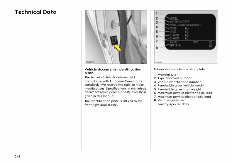
248
Technical Data
Vehicle docum ents, identification plate The tec hnical d ata is determined in accordance with European Community standards. We reserve the right to make modifications. Specifications in the vehic le docum ents alwa ys have priority over those given in this manual.
The identification plate is affixed to the front right door frame.
Information on identification plate:
1 Manufac turer 2 Type approval number 3 Vehic le identification number 4 Permissible gross vehicle weight 5 Permissible gross train weight 6 Maximum permissib le front axle load 7 Maximum permissib le rear axle load 8 Vehic le-specific or
country-specific data
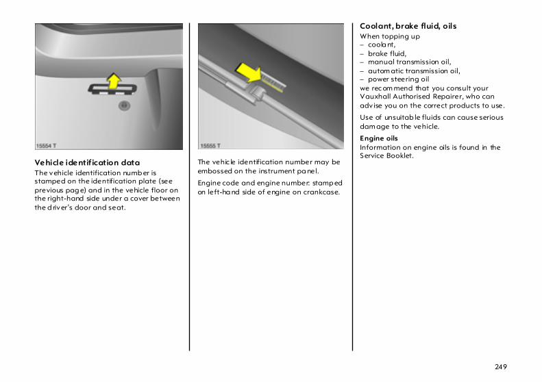
249
Vehicle identif ication data The vehicle identification numb er is stamped on the identification plate (see previous pag e) and in the vehicle floor on the right-hand side under a cover between the d river’s door and seat.
The vehic le identification number may be embossed on the instrument pa nel.
Engine code and engine number: stamp ed on left-ha nd side of engine on crankcase.
Coolant, brake fluid, oils When topping up – coola nt,– brake fluid, – manual transmission oil,– autom atic transmission oil,– power steering oilwe rec om mend that you consult your Vauxhall Authorised Repairer, who can adv ise you on the correct products to use.
Use of unsuitab le fluids can cause serious dam age to the vehicle.
Engine oils Information on engine oils is found in the Service Booklet.
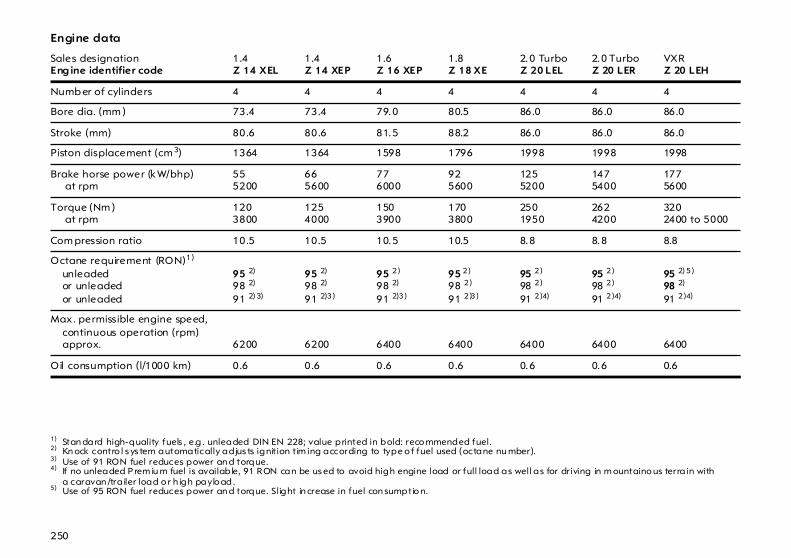
250
Engine data
Sales designationEng ine identifier code
1.4 Z 14 XEL
1.4 Z 14 XEP
1.6 Z 16 XEP
1.8 Z 18 XE
2.0 TurboZ 20 LEL
2.0 TurboZ 20 LER
VXRZ 20 LEH
Numb er of cylinders 4 4 4 4 4 4 4
Bore dia. (mm ) 73.4 73.4 79.0 80.5 86.0 86.0 86.0
Stroke (mm) 80.6 80.6 81.5 88.2 86.0 86.0 86.0
Piston displacement (cm 3) 1364 1364 1598 1796 1998 1998 1998
Brake horse power (kW/bhp) at rpm
555200
665600
776000
925600
1255200
1475400
1775600
Torque (Nm ) at rpm
1203800
1254000
1503900
1703800
2501950
2624200
3202400 to 5000
Com pression ratio 10.5 10.5 10.5 10.5 8.8 8.8 8.8
Octane requirement (RON)1)
unleadedor unleadedor unleaded
1) Stan dard high-quality fuels , e.g . unleaded DIN EN 228; value printed in bold: reco mmended fuel.
95 2)
98 2)
91 2) 3)
2) Kn ock contro l s ys tem automatically adjus ts ignition tim ing according to type o f fuel used (octane nu mber).
95 2)
98 2)
91 2)3)
3) Use of 91 RON fuel reduces power an d torque.
95 2)
98 2)
91 2)3)
95 2)
98 2)
91 2)3)
95 2)
98 2)
91 2)4)
4) If no unleaded P rem iu m fuel is available, 91 RON can be us ed to avoid high engine load or full load as well as for driving in m ountaino us terra in with a caravan /tra iler load o r h igh paylo ad.
95 2)
98 2)
91 2)4)
95 2) 5)
98 2)
91 2)4)
5) Use of 95 RON fuel reduces power an d torque. Slight in crease in fuel con sumptio n.
Max. permissible engine speed,continuous operation (rpm) approx. 6200 6200 6400 6400 6400 6400 6400
Oil consumption (l/1000 km) 0.6 0.6 0.6 0.6 0.6 0.6 0.6
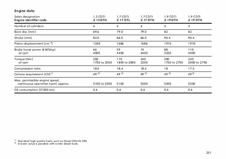
251
Engine data
Sales designationEng ine identifier code
1.3 CDTIZ 13 DTH
1.7 CDTI Z 17 DTL
1.7 CDTI Z 17 DTH
1.9 CDTI Z 19 DTH
1.9 CDTI Z 19 DTH
Numb er of cylinders 4 4 4 4 4
Bore dia. (mm ) 69.6 79.0 79.0 82 82
Stroke (mm) 82.0 86.0 86.0 90.4 90.4
Piston displacement (cm 3) 1248 1686 1686 1910 1910
Brake horse power (kW/bhp) at rpm
664000
594400
744400
883250
1104000
Torque (Nm ) at rpm
2001750 to 2500
1701800 to 2800
2402300
2801750 to 2750
3202000 to 2750
Com pression ratio 18.0 18.4 18.4 18 17.5
Cetane requirement (CN)1)
1) Stan dard high quality fuels, such as Diesel DIN EN 590.
49 2) 49 2)
2) A lo wer value is pos sib le with w inter diesel fu els.
49 2) 49 2) 49 2)
Max. permissible engine speed,continuous operation (rpm) approx. 5100 to 5300 5100 5200 5200 5200
Oil consumption (l/1000 km) 0.6 0.6 0.6 0.6 0.6

252
Perform ance (approx. mph / km/h),Hatch, 5-door
Eng ine1)
1) Sa les designation – see pages 250, 251.
Z 14 XEL Z 14 XEP Z 16 XEP Z 18 XE Z 20 LEL Z 20 LER
Maximum speed2)
Manual tra nsmissionEasytronicAutomatic transmission
2) The maxim um s peed is ach ievable with a m aximum of h alf payload. Optional equipm ent m ay reduce th e specified m aximum speed of the vehicle.
103/166––
111/178– –
115/185115/185–
123/198–117/188
135/217––
143/230––
Eng ine1) Z 13 DTH Z 17 DTL Z 17 DTH Z 19 DTH
Maximum speed2)
Manual tra nsmissionEasytronicAutomatic transmission
108/174––
104/168––
112/180––
119/1913)/129/2084)
––
3) Version w ith 88 kW. 4) Version w ith 110 kW.

253
Perform ance (approx. mph / km/h),Hatch, 3-door
Eng ine1)
1) Sa les designation – see pages 250, 251.
Z 14 XEL Z 14 XEP Z 16 XEP Z 18 XE Z 20 LEL Z 20 LER Z 20 LEH
Maximum speed2)
Manual tra nsmissionEasytronicAutomatic transmission
2) The maxim um s peed is ach ievable with a m aximum of h alf payload. Optional equipm ent m ay reduce th e specified m aximum speed of the vehicle.
104/168––
112/180– –
116/187116/187–
124/200–118/190
137/220––
145/234––
152/244––
Eng ine1) Z 13 DTH Z 17 DTL Z 17 DTH Z 19 DTH
Maximum speed2)
Manual tra nsmissionEasytronicAutomatic transmission
108/174––
106/170––
113/182––
120/1933)/130/2104)
––
3) Version w ith 88 kW. 4) Version w ith 110 kW.
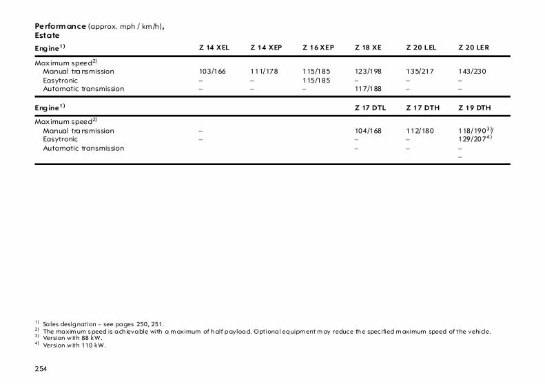
254
Perform ance (approx. mph / km /h),Estate
Eng ine1)
1) Sa les designation – see pages 250, 251.
Z 14 XEL Z 14 XEP Z 16 XEP Z 18 XE Z 20 LEL Z 20 LER
Maximum speed2)
Manual tra nsmissionEasytronicAutomatic transmission
2) The maxim um s peed is ach ievable with a m aximum of h alf payload. Optional equipm ent m ay reduce th e specified m aximum speed of the vehicle.
103/166––
111/178– –
115/185115/185–
123/198–117/188
135/217––
143/230––
Eng ine1) Z 17 DTL Z 17 DTH Z 19 DTH
Maximum speed2)
Manual tra nsmissionEasytronicAutomatic transmission
––
104/168––
112/180––
118/1903)/129/2074)
––
3) Version w ith 88 kW. 4) Version w ith 110 kW.
255
Fuel consumption,CO2 emissions Directive 80/1268/EEC (last c hanged by 1999/100/EC) has ap plied for the measurement of fuel consumption since 1996.
The direc tive is oriented to actual driving practices: Urba n driving is rated at approx. 1/3 and off-road driving with approx. 2/3 (urban and extra-urban consumption). Cold sta rts a nd acceleration phases are also taken into considera tion.
The specification of CO2 emission is also a constituent of the directive.
The figures given m ust not be taken as a guarantee for the actual fuel consumption of a p artic ular vehicle.
The calculation of fuel consumption as spec ified by directive 1999/100/EC takes acc ount of the vehicle’s kerb weight, ascertained in accordance with these regula tions. Optional extras ma y result in slightly higher fuel consumption and CO2 emission levels than those quoted.
To convert l/100 km into mpg, divide 282 by the number of litres / 100 km.
Saving fuel, p rotecting the environm ent – see page 152.
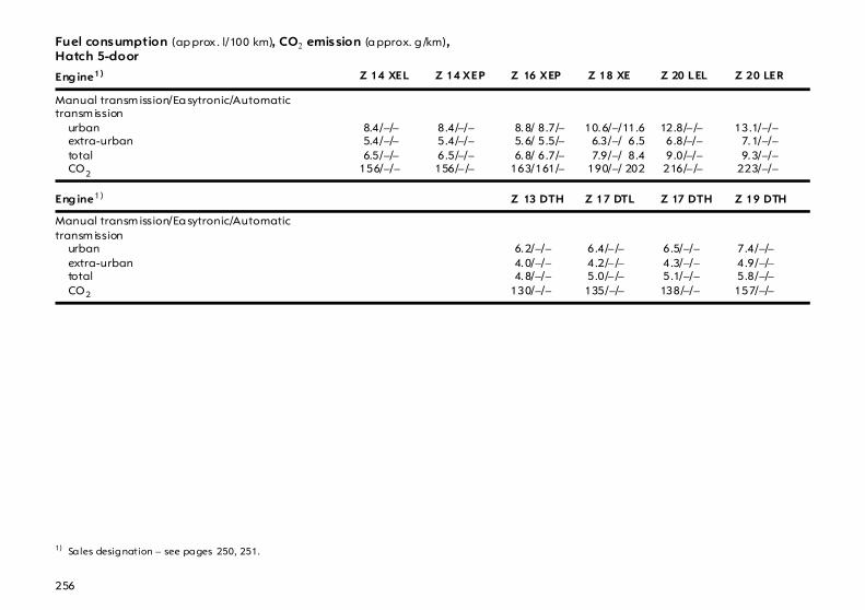
256
Fuel consumption (ap prox . l/100 km), CO2 emission (a pprox. g /km),Hatch 5-door
Eng ine1)
1) Sa les designation – see pages 250, 251.
Z 14 XEL Z 14 XEP Z 16 XEP Z 18 XE Z 20 LEL Z 20 LER
Manual transm ission/Ea sytronic/Automatic transm ission
urban extra-urbantotalCO2
8.4/–/– 5.4/–/– 6.5/–/–156/–/–
8.4/–/– 5.4/–/– 6.5/–/–156/– /–
8.8/ 8.7/– 5.6/ 5.5/– 6.8/ 6.7/–163/161/–
10.6/–/11.6 6.3/–/ 6.5 7.9/–/ 8.4 190/–/ 202
12.8/– /– 6.8/–/– 9.0/–/– 216/– /–
13.1/–/– 7.1/–/– 9.3/–/– 223/–/–
Eng ine1) Z 13 DTH Z 17 DTL Z 17 DTH Z 19 DTH
Manual transm ission/Ea sytronic/Automatic transm ission
urbanextra-urbantotalCO2
6.2/–/– 4.0/–/– 4.8/–/–130/–/–
6.4/– /– 4.2/– /– 5.0/– /–135/–/–
6.5/–/– 4.3/–/– 5.1/–/–138/–/–
7.4/–/– 4.9/–/– 5.8/–/–157/–/–

257
Fuel consumption (ap prox . l/100 km), CO2 emission (a pprox. g /km),Hatch 3-door
Eng ine1)
1) Sa les designation – see pages 250, 251.
Z 14 XEL Z 14 XEP Z 16 XEP Z 18 XE Z 20 LEL Z 20 LER Z 20 LEH
Manual transm ission/Ea sytronic/Automatic transm ission
urbanextra-urbantotalCO2
8.4/–/– 5.4/–/– 6.5/–/–156/–/–
8.4/–/– 5.4/–/– 6.5/–/–156/–/–
8.8/ 8.7/– 5.6/ 5.5/– 6.8/ 6.7/–163/161/–
10.6/–/11.5 6.3/–/ 6.4 7.9/–/ 8.3 190/–/ 199
12.8/–/– 6.8/–/– 9.0/–/– 216/–/–
13.1/–/– 7.1/–/– 9.3/–/– 223/–/–
2)
2) Values no t available at t im e of printing.
Eng ine1) Z 13 DTH Z 17 DTL Z 17 DTH Z 19 DTH
Manual transm ission/Ea sytronic/Automatic transm ission
urbanextra-urbantotalCO2
6.2/– /– 4.0/– /– 4.8/– /–130/– /–
6.4/– /– 4.2/– /– 5.0/– /–135/–/–
6.5/–/– 4.3/–/– 5.1/–/–138/–/–
7.4/–/– 4.9/–/– 5.8/–/–157/–/–
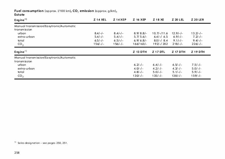
258
Fuel consumption (ap prox . l/100 km), CO2 emission (a pprox. g /km),Estate
Eng ine1)
1) Sa les designation – see pages 250, 251.
Z 14 XEL Z 14 XEP Z 16 XEP Z 18 XE Z 20 LEL Z 20 LER
Manual transm ission/Ea sytronic/Automatic transm ission
urbanextra-urbantotalCO2
8.4/–/– 5.4/–/– 6.5/–/–156/–/–
8.4/–/– 5.4/–/– 6.5/–/–156/– /–
8.9/ 8.8/– 5.7/ 5.6/– 6.9/ 6.8/–166/163/–
10.7/–/11.6 6.4/–/ 6.5 8.0/–/ 8.4 192/–/ 202
12.9/– /– 6.9/–/– 9.1/–/– 218/– /–
13.2/–/– 7.2/–/– 9.4/–/– 226/–/–
Eng ine1) Z 13 DTH Z 17 DTL Z 17 DTH Z 19 DTH
Manual transm ission/Ea sytronic/Automatic transm ission
urbanextra-urbantotalCO2
6.2/–/– 4.0/–/– 4.8/–/–130/–/–
6.4/– /– 4.2/– /– 5.0/– /–135/–/–
6.5/–/– 4.3/–/– 5.1/–/–138/–/–
7.5/–/– 5.0/–/– 5.9/–/–159/–/–

259
Weights, payload and roof load The p ayload is the difference between the permitted g ross vehicle weight (see identification plate, page 248) and the EC kerb weight.
To calculate the kerb weight, enter the data for your vehicle below: z Kerb weight from
Ta ble 1,page 260 + ... ..... .... .. kg
z Ad ditional w eight ofequipment versions fromTa ble 2, p age 263 + ... ..... .... .. kg
z Weight of heavyaccessories from Table 3,page 264 + ... ..... .... .. kg
The total = ... ..... .... .. kg
is the EC kerb w eight.
Optional equipment and accessories increase the kerb weight, which m eans that the p ayload will also change slig htly.
Note the weights given in the vehicle documents.
The combined total of front a nd rear ax le loa ds must not exceed the perm issible gross vehicle weight. For exa mple, if the front ax le is bearing its m aximum permissib le load, the rear axle can only bear a load that is eq ua l to the gross vehicle weig ht m inus the front axle load.
With a tra iler coupled and the towing vehicle fully loaded (including a ll oc cup ants) the permissible rear axle load (see identification plate or vehic le docum ents) may be exceeded by 65 kg and perm issible gross vehicle weight by 45 kg for the Hatch. For the Estate, the permissib le rear axle load m ay be exc eeded by 60 kg a nd the permissible gross vehicle weight by 30 kg. If the permissib le rear axle load is exceeded, a maximum speed of 60 m ph (100 km/h) applies. I f na tional regulations specify a low er ma ximum speed for vehicles towing a trailer, this must be observed.
See the identification plate or vehicle docum ents for permissib le ax le loads.
Roof loa dThe permissib le roof load is 75 kg and 100 kg for caravan w ith roof railing. The roof load is the c om bined weight of the roof rack a nd the load.
Driving hints – see page 150. R oof racks, caravan and trailer towing – see pag e 186.

260
Weight (kg), Table 1 , kerb weight1) , Hatch 5-door
1) According to EC D irective, inclu ding ass umed weights for driver (68 kg), luggage (7 kg) and a ll f lu ids (tank 9 0 % fu ll). 2) Sales designation – see pages 250, 251.
Model Engine2) Manual t ransmission Ea sytronic Automat ic transm ission
Astra Z 14 XEL 1230 – –
Z 14 XEP 1230 – –
Z 16 XEP 1265 1265 –
Z 18 XE 1278 – 1310
Z 13 DTH 1330 – –
Z 17 DTL 1335 – –
Z 17 DTH 1365 – –
Z 19 DTH 1393 – –
Astrawithair conditioning system orclim ate control system
Z 14 XEL 1250 – –
Z 14 XEP 1250 – –
Z 16 XEP 1285 1285 –
Z 18 XE 1298 – 1330
Z 20 LEL 1385 – –
Z 20 LER 1385 – –
Z 13 DTH 1345 – –
Z 17 DTL 1350 – –
Z 17 DTH 1380 – –
Z 19 DTH 1408 – –
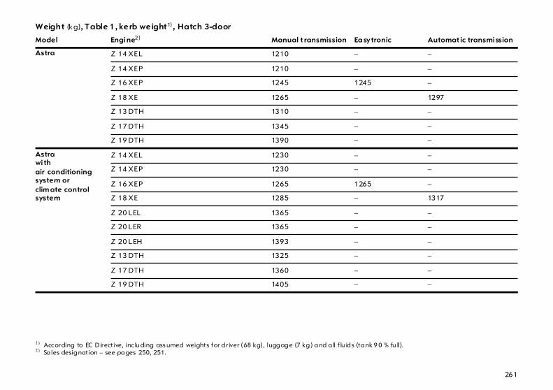
261
Weight (kg), Table 1 , kerb weight1) , Hatch 3-door
1) According to EC D irective, inclu ding ass umed weights for driver (68 kg), luggage (7 kg) and a ll f lu ids (tank 9 0 % fu ll). 2) Sales designation – see pages 250, 251.
Model Engine2) Manual t ransmission Ea sytronic Automat ic transmission
Astra Z 14 XEL 1210 – –
Z 14 XEP 1210 – –
Z 16 XEP 1245 1245 –
Z 18 XE 1265 – 1297
Z 13 DTH 1310 – –
Z 17 DTH 1345 – –
Z 19 DTH 1390 – –
Astrawithair conditioning system orclim ate control system
Z 14 XEL 1230 – –
Z 14 XEP 1230 – –
Z 16 XEP 1265 1265 –
Z 18 XE 1285 – 1317
Z 20 LEL 1365 – –
Z 20 LER 1365 – –
Z 20 LEH 1393 – –
Z 13 DTH 1325 – –
Z 17 DTH 1360 – –
Z 19 DTH 1405 – –

262
Weights (kg): Table 1, Kerb weight1), Estate
1) According to EC D irective, inclu ding ass umed weights for driver (68 kg), luggage (7 kg) and a ll f lu ids (tank 9 0 % fu ll). 2) Sales designation – see pages 250, 251.
Model Engine2) Manual t ransmission Ea sytronic Autom atic t ransmission
Astra Z 14 XEL 1280 – –
Z 14 XEP 1280 – –
Z 16 XEP 1315 1315 –
Z 18 XE 1325 – 1350
Z 17 DTL 1380 – –
Z 17 DTH 1393 – –
Z 19 DTH 1450 – –
Astrawithair conditioning system orclim ate control system
Z 14 XEL 1300 – –
Z 14 XEP 1300 – –
Z 16 XEP 1335 1335 –
Z 18 XE 1345 – 1370
Z 20 LEL 1425 – –
Z 20 LER 1425 – –
Z 17 DTL 1395 – –
Z 17 DTH 1408 – –
Z 19 DTH 1465 – –
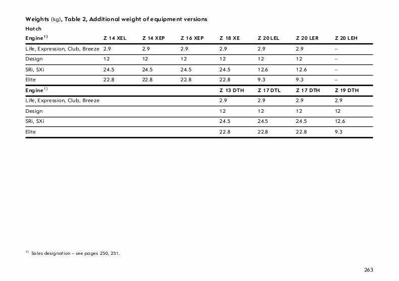
263
Weights (kg), Table 2, Additional weight of equipment versions
Hatch
Eng ine1)
1) Sa les designation – see pages 250, 251.
Z 14 XEL Z 14 XEP Z 16 XEP Z 18 XE Z 20 LEL Z 20 LER Z 20 LEH
Life, Expression, Club, Breeze 2.9 2.9 2.9 2.9 2.9 2.9 –
Design 12 12 12 12 12 12 –
SRi, SXi 24.5 24.5 24.5 24.5 12.6 12.6 –
Elite 22.8 22.8 22.8 22.8 9.3 9.3 –
Eng ine1) Z 13 DTH Z 17 DTL Z 17 DTH Z 19 DTH
Life, Expression, Club, Breeze 2.9 2.9 2.9 2.9
Design 12 12 12 12
SRi, SXi 24.5 24.5 24.5 12.6
Elite 22.8 22.8 22.8 9.3
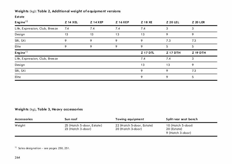
264
Weights (kg): Table 2, Additional weight of equipment versions
Estate
Eng ine1)
1) Sa les designation – see pages 250, 251.
Z 14 XEL Z 14 XEP Z 16 XEP Z 18 XE Z 20 LEL Z 20 LER
Life, Expression, Club, Breeze 7.4 7.4 7.4 7.4 3 3
Design 13 13 13 13 9 9
SRi, SXi 9 9 9 9 7.3 7.3
Elite 9 9 9 9 5 5
Eng ine1) Z 17 DTL Z 17 DTH Z 19 DTH
Life, Expression, Club, Breeze 7.4 7.4 3
Design 13 13 9
SRi, SXi 9 9 7.3
Elite 9 9 5
Weights (kg), Table 3, Heavy accessories
Accessories Sun roof Towing equipment S plit r ear seat benc h
Weight 25 (Hatch 5-door, Estate)23 (Hatch 3-door)
22 (H atch 5-door, Estate)20 (H atch 3-door)
10 (Hatch 5-door)20 (Estate)9 (Hatch 3-door)

265
Tyres Restrictions Not a ll tyres ava ila ble on the market currently meet the structural requirem ents. We recommend that you consult a Vauxhall Authorised Repairer concerning suitab le tyre makes.
These ty res have und ergone special tests to establish their reliab ility , safety and specific suitability for Vauxhall vehicles. Despite continuous ma rket monitoring, we are unab le to assess these attributes for other tyres, even if they have been g ra nted approva l by the relevant authorities or in som e other form.
Further information – see pa ge 180.
Winter tyres 3 Tyres of size 215/45 R 17, 225/45 R 17, 225/40 R 18 and 235/35 R 19 a re not to be used as winter tyres.
If winter tyres are in use, the spa re wheel may still be fitted with a summer tyre. Use of the spare wheel may alter vehicle handling . Obtain a replacem ent for the faulty tyre as soon a s possib le, and have the w heel balanced and fitted to the vehic le.
Further information – see pa ge 184.
Tyre chains 3 Restrictions Tyre c hains may be used on the front wheels only.
We recommend the use of Vauxhall-tested fine-mesh tyre chains that a dd no more than 15 mm to the tyre trea d and the inboard sides (including chain lock).
Do not use tyre c ha ins on tem pora ry spare wheel 115/70 R 16 or tyres of size 215/45 R 17, 225/45 R 17, 225/40 R 18 and 235/35 R 19.
Further inform ation – see page 185.
Wheels Wheel bolt tightening torque: 110 Nm.
Depend ing on the version, the spare w heel may ta ke the form of a temporary spare wheel: vehicle driveability m ay be altered by use of the sp are wheel. Obtain a replacement for the faulty tyre as soon as possible, and have the w heel balanced and fitted to the vehicle.
Tyre pressure in bar1) The specified ty re pressures are valid for cold ty res. The increased tyre pressure resulting from extensive d riv ing must not be reduced. The tyre pressures specified on the following pages ap ply to both summer and w inter tyres.
Always inflate the spare wheel to the tyre pressure for full load – see ta bles on following pages.
Temporary spare wheel tyre pressure – see tables on next pa ge.
In vehicles with tyre pressure monitoring system 3 there is an adapter in the valve cap key . Screw a dapter to valve before attaching tyre pressure gauge – see pag e 181.
Further information – see pa ges 180 to 185.
1) 1 bar correspon ds to 100 kPa/ 14.5 psi.

266
(ctd.)Tyre pressure in bar/psi1)
1) 1 bar corresponds to 100 kPa/14.5 psi.
Hatch Tyre pressurefor load ofup to 3 persons
Tyre pressure ECO2)
load edup to 3 people
Tyre pressurefor full load
Engine3) Tyres Front Rear Front Rear Front Rear
Z 14 XEP,Z 16 XEP,Z 18 XE
185/65 R 15,195/60 R 15,215/45 R 17,225/40 R 18
2.3/33 2.1/30 – – 2.5/36 2.9/42
195/65 R 15,205/55 R 16225/45 R 17
1.9/27 1.9/27 2.4/35 2.4/35 2.0/29 2.5/36
Z 14 XEL 185/65 R 15,195/60 R 15
2.3/33 2.1/30 – – 2.5/36 2.9/42
195/65 R 15,205/55 R 16225/45 R 17
1.9/27 1.9/27 2.4/35 2.4/35 2.0/29 2.5/36
Z 20 LEL 205/55 R 16,225/45 R 17
2.3/33 2.1/30 2.7/39 2.5/36 2.5/36 2.9/42
215/45 R 17,225/40 R 18
2.5/36 2.3/33 – – 2.6/38 3.0/44
2) To achieve the low es t possib le fuel con sumptio n. 3) Sales designation – s ee pages 250, 25 1. 4) For notes on the temporary spare w heel – see page 202.
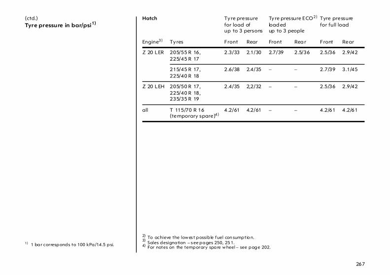
267
(ctd.)Tyre pressure in bar/psi1)
1) 1 bar corresponds to 100 kPa/14.5 psi.
Hatch Tyre pressurefor load ofup to 3 persons
Tyre pressure ECO2)
load edup to 3 people
Tyre pressurefor full load
Engine3) Tyres Front Rear Front Rea r Front Rear
Z 20 LER 205/55 R 16,225/45 R 17
2.3/33 2.1/30 2.7/39 2.5/36 2.5/36 2.9/42
215/45 R 17,225/40 R 18
2.6/38 2.4/35 – – 2.7/39 3.1/45
Z 20 LEH 205/50 R 17,225/40 R 18,235/35 R 19
2.4/35 2,2/32 – – 2.5/36 2.9/42
all T 115/70 R 16(temporary spare)4)
4.2/61 4.2/61 – – 4.2/61 4.2/61
2) To achieve the low es t possib le fuel con sumptio n. 3) Sales designation – s ee pages 250, 25 1. 4) For notes on the temporary spare w heel – see page 202.

268
(ctd.)Tyre pressure in bar/psi1)
1) 1 bar corresponds to 100 kPa/14.5 psi.
Hatch Tyre pressurefor load ofup to 3 persons
Tyre pressure ECO2)
load edup to 3 people
Tyre pressurefor full load
Engine3) Tyres Front Rear Front Rea r Front Rear
Z 13 DTH 195/65 R 15,205/55 R 16
2.1/30 2.1/30 2.5/36 2.5/36 2.5/36 2.9/42
Z 17 DTL 185/65 R 15,195/60 R 15,215/45 R 17,225/40 R 18
2.3/33 2.1/30 – – 2.5/36 2.9/42
195/65 R 15,205/55 R 16,225/45 R 17
2.1/30 2.1/30 2.5/36 2.5/36 2.5/36 2.9/42
Z 17 DTH 195/65 R 15,205/55 R 16,225/45 R 17
2.1/30 2.1/30 2.5/36 2.5/36 2.5/36 2.9/42
215/45 R 17,225/40 R 18
2.5/36 2.3/33 – – 2.6/38 3.0/44
Z 19 DTH 205/55 R 16,225/45 R 17
2.3/33 2.1/30 2.7/39 2.5/36 2.5/36 2.9/42
215/45 R 17,225/40 R 18
2.6/38 2.4/35 – – 2.7/39 3.1/45
all T 115/70 R 16(tem pora ry spare)4)
4.2/61 4.2/61 – – 4.2/61 4.2/61
2) To achieve the low es t possib le fuel con sumptio n. 3) Sales designation – s ee pages 250, 25 1. 4) For notes on the temporary spare w heel – see page 202.

269
(ctd.)Tyre pressure in bar/psi1)
1) 1 bar corresponds to 100 kPa/14.5 psi.
Estate Tyre pressurefor load ofup to 3 persons
Tyre p ressure ECO2)
load edup to 3 people
Tyre pressurefor full load
Engine3) Tyres Front Rear Front Rear Front Rear
Z 14 XEP,Z 16 XEP,Z 18 XE
195/65 R 15,205/55 R 16225/45 R 17
2.0/29 2.0/29 2.5/36 2.5/36 2.1/30 2.6/38
185/65 R 15,195/60 R 15,215/45 R 17,225/40 R 18
2.3/33 2.1/30 – – 2.5/36 2.9/42
Z 14 XEL 195/65 R 15,205/55 R 16225/45 R 17
2.0/29 2.0/29 2.5/36 2.5/36 2.1/30 2.6/38
185/65 R 15,195/60 R 15
2.3/33 2.1/30 – – 2.5/36 2.9/42
Z 20 LEL 205/55 R 16,225/45 R 17
2.3/33 2.1/30 2.7/39 2.5/36 2.5/36 2.9/42
215/45 R 17,225/40 R 18
2.5/36 2.3/33 – – 2.6/38 3.0/44
Z 20 LER 205/55 R 16225/45 R 17
2.3/33 2.1/30 2.7/39 2.5/36 2.5/36 2.9/42
215/45 R 17,225/40 R 18
2.7/39 2.5/36 – – 2.8/41 3.1/45
all T 115/70 R 16(tem pora ry spare)4)
4.2/61 4.2/61 – – 4.2/61 4.2/61
2) To achieve the low es t possib le fuel con sumptio n. 3) Sales designation – s ee pages 250, 25 1. 4) For notes on the temporary spare w heel – see page 202.

270
(ctd.)Tyre pressure in bar/psi1)
1) 1 bar corresponds to 100 kPa/14.5 psi.
Estate Tyre pressurefor load ofup to 3 persons
Tyre pressure ECO2)
loadedup to 3 people
Tyre pressurefor full load
Engine3) Tyres Front Rear Front Rear Front Rear
Z 17 DTL 195/65 R 15,205/55 R 16,225/45 R 17
2.1/30 2.1/30 2.5/36 2.5/36 2.5/36 2.9/42
215/45 R 17,225/40 R 18
2.3/33 2.1/30 – – 2.5/36 2.9/42
Z 17 DTH 195/65 R 15,205/55 R 16,225/45 R 17
2.1/30 2.1/30 2.5/36 2.5/36 2.5/36 2.9/42
215/45 R 17,225/40 R 18
2.5/36 2.3/33 – – 2.6/38 3.0/44
Z 19 DTH 205/55 R 16,225/45 R 17
2.3/33 2.1/30 2.7/39 2.5/36 2.5/36 2.9/42
215/45 R 17,225/40 R 18
2.7/39 2.5/36 – – 2.8/41 3.1/45
all T 115/70 R 16(temporary spare)4)
4.2/61 4.2/61 – – 4.2/61 4.2/61
2) To achieve the low es t possib le fuel con sumptio n. 3) Sales designation – s ee pages 250, 25 1. 4) For notes on the temporary spare w heel – see page 202.
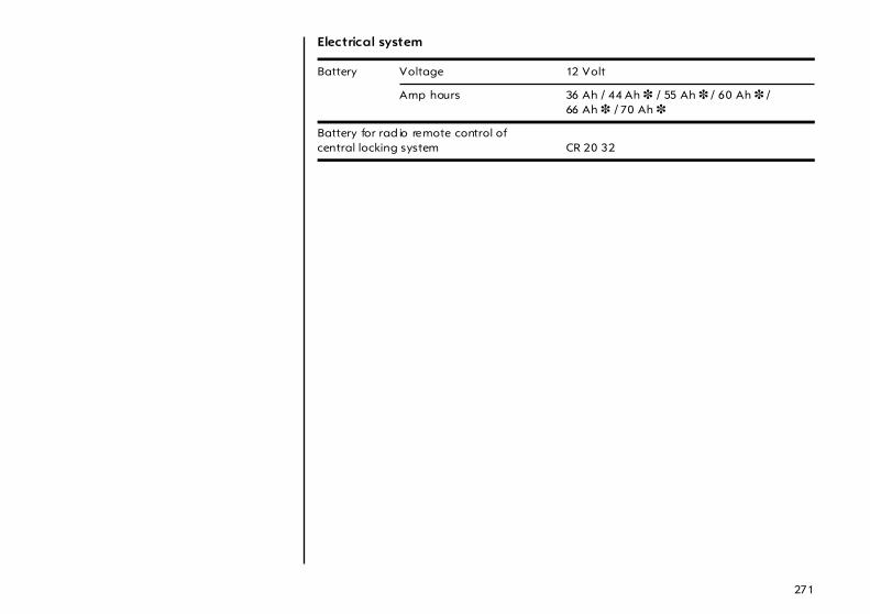
271
Electrical system
Battery Voltage 12 Volt
Amp hours 36 Ah / 44 Ah 3 / 55 Ah 3 / 60 Ah 3 /66 Ah 3 / 70 Ah 3
Battery for rad io remote control ofcentral locking system CR 20 32
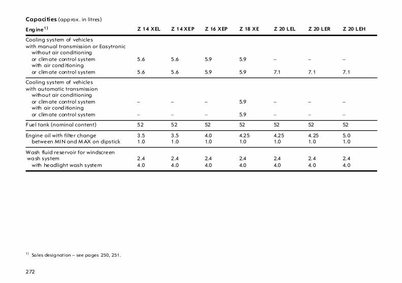
272
Capacities (app rox . in litres)
Eng ine1)
1) Sa les designation – see pages 250, 251.
Z 14 XEL Z 14 XEP Z 16 XEP Z 18 XE Z 20 LEL Z 20 LER Z 20 LEH
Cooling system of vehicleswith manual transmission or Easytronic
without air conditioningor clim ate control systemwith air cond itioningor clim ate control system
5.6
5.6
5.6
5.6
5.9
5.9
5.9
5.9
–
7.1
–
7.1
–
7.1
Cooling system of vehicleswith automatic transmission
without air conditioningor clim ate control systemwith air cond itioningor clim ate control system
–
–
–
–
–
–
5.9
5.9
–
–
–
–
–
–
Fuel tank (nominal content) 52 52 52 52 52 52 52
Engine oil with filter changebetween MIN and M AX on dipstick
3.51.0
3.51.0
4.01.0
4.251.0
4.251.0
4.251.0
5.01.0
Wash fluid reservoir for windscreen wa sh system
with headlight wash system2.44.0
2.44.0
2.44.0
2.44.0
2.44.0
2.44.0
2.44.0
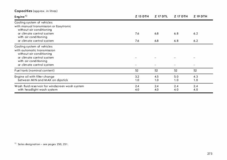
273
Capacities (app rox . in litres)
Eng ine1)
1) Sa les designation – see pages 250, 251.
Z 13 DTH Z 17 DTL Z 17 DTH Z 19 DTH
Cooling system of vehicleswith manual transmission or Easytronic
without air conditioningor clim ate control systemwith air cond itioningor clim ate control system
7.6
7.6
6.8
6.8
6.8
6.8
6.2
6.2
Cooling system of vehicleswith automatic transmission
without air conditioningor clim ate control systemwith air cond itioningor clim ate control system
–
–
–
–
–
–
–
–
Fuel tank (nominal content) 52 52 52 52
Engine oil with filter changebetween MIN and M AX on dipstick
3.21.0
4.51.0
5.01.0
4.31.0
Wash fluid reservoir for windscreen wa sh systemwith headlight wash system
2.44.0
2.44.0
2.44.0
2.44.0

274
Dimensions (approx. mm)
Hatc h 5-door Ha tch 3-door Estate
Overall length 4249 4290 4515
Width 1753 1753 1753
Width with two exterior mirrors 2033 2033 2033
Overall height 1460 1435 1500
Wheelb ase 2614 2614 2703
Turning c ircle diam eter1)
1) In metres.
11.20 11.20 11.50

275
Mounting dim ensions ofcaravan/trailer towing equipment with removable coupling ball bar,Hatch1) All dimensions refer to fac tory-fitted towing equipm ent.
1) Do no t mo unt to wing equipm ent to vehicles with Z 20 LEH en gine. Sales des ignation – see page 250.
Dimension mm
A 342.9
B 83
C 513.4
D 488.6
E 211.4
F 94.3
G 160
Only use towing equipment approved for your vehicle. We recommend entrusting retrofitting of tow ing equipment to your Va uxha ll Authorised Repairer.

276
Mounting dim ensions ofcaravan/trailer towing equipment with removable coupling ball bar,Estate All dimensions refer to fac tory-fitted towing equipm ent.
Dimension mm
A 84.0
B 570.0
C 515.0
D 93.5
E 173.0
F 307.6
G 158.0
H 292.6
Only use towing equipment approved for your vehicle. We recommend entrusting retrofitting of tow ing equipment to your Va uxha ll Authorised Repairer.

277

278
Index A
AB S (Anti-lock Brake System ).. ..... .... .... 178Ac cessories. ..... .... ..... .... . 104, 107, 200, 201Ac cessory socket ..... .... ..... .... .... ..... .... ..... . 83Ad aptive brake light ... ..... .... .... ..... .... .... 176Ad aptive Forward Lighting (AFL) .... .... 111
Driving abroad ..... .... ..... .... .... ..... .... .... 114Aerial .. .... .... ..... .... ..... .... ..... .... .... ..... .. 52, 245Air conditioning system ... .... .... ..... .... .... 120Air intake.... ..... .... ..... .... ..... .... .... ..... .... .... 134Air outlet .... ..... .... ..... .... ..... .... .... ..... .... .... 134Air qua lity sensor ..... .... ..... .... .... ..... .... .... 128Air recirculation system .... .... .... ..... 122, 132Air vents . .... ..... .... ..... .... ..... .... .... ..... .... .... 123Airba gs... .... ..... .... ..... .... ..... .... .... ..... .... ..... . 93Ala rm system .. .... ..... .... ..... .... .... ..... .... ..... . 63Alterna tor ... ..... .... ..... .... ..... .... .... ..... .... ..... . 27Anti-corrosion service.. ..... .... .... ..... .... .... 233Antifreeze... ..... .... ..... .... ..... .... .... ..... .... .... 236Antifreeze protection .. ..... .... .... ..... 236, 241Anti-knock q ua lity of fuel .... .... ..... .... .... 154
Octane number.... .... ..... .... .... ..... .... .... 250Anti-theft locking system . .... .... ..... .... ..... . 58
Towing equip ment .. ..... .... .... ..... .... .... 189Anti-theft protection ... ..... .... .... ..... .... ..... . 23Aq ua planing ... .... ..... .... ..... .... .... ..... .... .... 184Arm rest... .... ..... .... ..... .... ..... .... .... ..... .... 69, 86Ashtray ... .... ..... .... ..... .... ..... .... .... ..... .. 84, 114Automatic
Anti-dazzle interior mirror.... ..... .... .... 106Automatic air recirculation mode 128, 132Automatic tra nsmission ... .... .... ..... .. 21, 144
Control indicator.. .... ..... .... .... ..... .... .... 146
Driv ing programme ..... .... ..... .... ..... .... 146Fault .. ..... .... ..... .... .... ..... .... ..... .... ..... .... 148Interruption of p ow er supply ... ..... .... 149Kickd ow n.... ..... .... .... ..... .... ..... .... ..... .... 147Selector lever... .... .... ..... .... ..... .... ..... .... .. 21Winter programme. ..... .... ..... .... ..... .... 147
Automatic wiping ... .... ..... .... ..... .... ..... .... .. 18
BBattery .. ..... .... ..... .... .... ..... .... .. 151, 242, 271
Interruption of power supply .. .... ..... .... .. 116, 142, 149
Before starting off .. .... ..... .... ..... .... ..... .... .. 21Belt tensioners .... .... .... ..... .... ..... .... ..... .... .. 88Bleeding, diesel fuel system .... .... ..... .... 195Board information display.. ..... .... ..... .... .. 34Bonnet ... ..... .... ..... .... .... ..... .... ..... .... ..... .... .. 66Brake assist .... ..... .... .... ..... .... ..... .... ..... .... 176Brake system . ..... .... .... ..... .... ..... .... ..... .... .. 27Brakes.... ..... .... ..... .... .... ..... .... ..... .... ..... .... 176
ABS .... ..... .... ..... .... .... ..... .... ..... .... ..... .... 178Brake assist ..... .... .... ..... .... ..... .... ..... .... 176Brake fluid .. ..... .... .... ..... .... ..... .... ..... .... 238Brake lights ..... .... .... ..... .... ..... .... . 224, 226Brake servo unit.. .... ..... .... ..... .... ..... .... 150Foot brake.. ..... .... .... ..... .... ..... .... ..... .... 176Hand brake..... .... .... ..... .... ..... .... ..... .... 177
Bulb replacem ent ... .... ..... .... ..... .... ..... .... 216Bulbs.. .... ..... .... ..... .... .... ..... .... ..... .... . 107, 216
279
C
Ca pacities ... .... ..... .... ..... .... ..... .... .... ..... ... 272Ca r Pass... .... .... ..... .... ..... .... ..... .... .... ..... .... ... 4Ca ra van/trailer tow ing . .... ..... .... .... 150, 186Ca re .... ..... .... .... ..... .... ..... .... ..... .... .... ..... ... 244Ca rg o box ... .... ..... .... ..... .... ..... .... .... ..... .... . 81Ca ta lytic converter .. ..... .... .... 157, 161, 195Central locking system . .... ..... .... .... ..... .... . 58Changing the battery
Radio rem ote control .... ..... .... .... .. 57, 271Changing tyre/w heel type..... .... .... ..... ... 180Changing wheels . .... ..... .... ..... .... .... ..... ... 203Check control .. ..... .... ..... .... ..... .... .... ..... .... . 50Child restraint system ... .... ..... .... .... 104, 107Child safety locks . .... ..... .... ..... .... .... .. 54, 116Ciga rette lig hter... .... ..... .... ..... .... .... .. 83, 114Clim ate control .... .... ..... .... ..... .... .... ..... ... 120Clim ate control system . .... ..... .... .... ..... ... 127Clock ... ..... .... .... ..... .... ..... .... ..... .... .... ..... .... . 32Clutch operation .. .... ..... .... ..... .... .... ..... ... 151CO2 em issions. ..... .... ..... .... ..... .... .... ..... ... 255Code numbers. ..... .... ..... .... ..... .... .... ..... .... ... 4Cold start . .... .... ..... .... ..... .... ..... .... .... ..... ... 151Colour inform ation d isplay ... .... .... ..... .... . 34
Continuous Damping Control (CDC) .... .... ..... .... ..... .... ..... .... .... ..... .. 28, 164
Contra st.. .... ..... .... ..... .... ..... .... .... ..... .... ..... . 45Control indica tor
ABS (Anti-lock Brake System) ... .... .... 179Airbag. .... ..... .... ..... .... ..... .... .... ..... .... ..... . 98Engine electronics .... ..... .... .... ..... .... .... 160Exhaust ... ..... .... ..... .... ..... .... .... ..... .... .... 159Imm obiliser.. .... ..... .... ..... .... .... ..... .... ..... . 55Parking distance sensor ... .... ..... .... .... 169Transm ission ... ..... .... ..... .... .... ..... .... .... 146Tyre pressure monitoring system . .... 174
Control indica tors .... .... ..... .... .... ..... .... 12, 26Adaptive Forward Lighting . ..... .... ..... . 30Adaptive Forward Lighting (AFL) .... 111Belt tensioners. ..... .... ..... .... .... ..... .... ..... . 89Brake system ... ..... .... ..... .... .... ..... .... .... 178Cruise c ontrol .. ..... .... ..... .... .... ..... .... .... 166DDS . .... .... ..... .... ..... .... ..... .... .... ..... .... .... 171Deflation detection system .. ..... .... .... 171ESP (Electronic Stability Program) .... 162IDS+ . .... .... ..... .... ..... .... ..... .... .... ..... 164, 165
Coolant... .... ..... .... ..... .... ..... .... .... ..... .... .... 236Coolant level ... .... ..... .... ..... .... .... ..... .... .... 237Coolant temp erature .. ..... .... .... ..... .... ..... . 27Cooling ... .... ..... .... ..... .... ..... .... .... ..... .... .... 125Correcting time ... ..... .... ..... .... .... ..... .... 38, 44Coupling socket load .. ..... .... .... ..... .... .... 192Courtesy light.. .... ..... .... ..... .... .... ..... .... .... 113Courtesy light delay .... ..... .... .... ..... .... .... 113
Courtesy lightsBulb replacement ... ..... .... ..... .... ..... .... 228
Cruise control. ..... .... .... ..... .... ..... .... ..... .... 166Curtain airbag s .. .... .... ..... .... ..... .... ..... .... .. 96Curve lighting ..... .... .... ..... .... ..... .... ..... .... 111
DData .. .... ..... .... ..... .... .... ..... .... ..... .... ... 55, 248Date... .... ..... .... ..... .... .... ..... .... ..... .... ..... 36, 39Daytim e running lights ... .... ..... .... ..... .... 108Decommissioning ... .... ..... .... ..... .... ..... .... 243Defla tion detection system. ..... .... ..... .... 171Defla tion Detection System (DDS) ... .... 171Demisting a nd defrosting
Windows . .... ..... .... .... ..... .... ..... .... ..... .... 125with climate control system . .... ..... .... 130With the air conditioning system . .... 126
Diesel fuel filter ... .... .... ..... .... ..... .... ..... .... 236Diesel fuel system ... .... ..... .... ..... .... . 195, 236Diesel particle filter .... ..... .... .... 30, 122, 151Dimensions. .... ..... .... .... ..... .... ..... .... ..... .... 273Dipped beam. ..... .... .... ..... .... ..... .... ... 15, 108
Bulb replacement ... ..... .... ..... .... . 217, 220Display .. ..... .... ..... .... .... ..... .... ..... .... ..... 33, 34Display m ode. ..... .... .... ..... .... ..... .... ..... .... .. 46Door handle lig hting .. ..... .... ..... .... ..... .... 114Door locks .. .... ..... .... .... ..... .... ..... .... ... 54, 247Doors. .... ..... .... ..... .... .... ..... .... ..... .... ..... .... .. 27Door-to-d oor light function ..... .... ..... .... 112Driving ab road ... .... .... ..... .... ..... .... . 154, 231
Head lig hts.. ..... .... .... ..... .... ..... .... ..... .... 114Driving hints... ..... .... .... ..... .... ..... .... ..... .... 150
280
E
Ea sytronic .... .... ..... .... ..... .... ..... .... .... .. 20, 136Driv ing programmes. .... ..... .... .... ..... ... 138fault. ..... .... .... ..... .... ..... .... ..... .... .... ..... ... 142Interrup tion of power sup ply .... ..... ... 142Kickdown . .... ..... .... ..... .... ..... .... .... ..... ... 140Selector lever .... .... ..... .... ..... .... .... ..... .... . 20Starting off .. ..... .... ..... .... ..... .... .... ..... ... 137Winter prog ra mme ... .... ..... .... .... ..... ... 139
Ec onomical driving .. ..... .... ..... .... .... 150, 152Electric sun roof ... .... ..... .... ..... .... .... ..... ... 118Electric windows... .... ..... .... ..... .... .... ..... ... 115Electrical system .. .... ..... .... .... 210, 242, 271Electro-hydraulic power assisted steering.. ..... .... .... ..... ... 150
Electro-hydraulic power-a ssisted steeringfluid . ..... .... .... ..... .... ..... .... ..... .... .... ..... ... 249
Electronic components . .... ..... .... .... ..... ... 242Electronic immobiliser... .... ..... .... .... ..... .... . 55Electronic Stability Program ..... .... ..... ... 162Engine code .... ..... .... ..... .... .... 249, 250, 251Engine control indicator ... ..... .... .... ..... ... 160Engine oil . .... .... ..... .... ..... .... ..... .... .... ..... ... 234Engine oil change .... ..... .... ..... .... .... 234, 235
Engine oil c onsumption.... .... .... ..... .... .... 234Engine oil filter .... ..... .... ..... .... .... ..... .... .... 235Engine oil level .... ..... .... ..... .... .... ..... .. 28, 234Engine speed .. .... ..... .... ..... .... .... ..... .... .... 151Engine w ash .... .... ..... .... ..... .... .... ..... .... .... 247Entry lighting... .... ..... .... ..... .... .... ..... .... .... 114Environmental protection .... . 234, 235, 244ESP (Electronic Stab ility Prog ra m).... .... 162Exhaust control indicator . .... .... ..... .... .... 159Exhaust gases . .... ..... .... ..... .... .... ..... .... .... 160Exhaust system ... ..... .... ..... .... .... ..... .... .... 160Exterior mirrors ... ..... .... ..... .... .... . 8, 106, 122
F
Fan .... .... ..... .... ..... .... .... ..... .... .. 121, 233, 234Filling station
Capac ities .. ..... .... .... ..... .... ..... .... . 272, 273Engine oil level .... .... ..... .... ..... .... ..... .... 234Fuel .... ..... .... ..... .... .... ..... .... .. 154, 250, 251Ignition key ..... .... .... ..... .... ..... .... ..... .... .... . 4Opening the bonnet .... .... ..... .... ..... .... .. 66Tyre pressure .. .... .... ..... .... ..... .... . 153, 265Vehic le da ta .... .... .... ..... .... ..... .... ..... .... 249Windscreen wash system ..... .... ..... .... 241
First-aid kit (cushion) . ..... .... .. 107, 200, 201Flat tyre. ..... .... ..... .... .... ..... .... ..... .... ..... .... 207FlexOrganizer ..... .... .... ..... .... ..... .... ..... .... .. 80Fog lights ... .... ..... .... .... ..... .... ..... .... ..... .... 109
Bulb replacement ... ..... .... ..... .... ..... .... 223Fog tail light... ..... .... .... ..... .... ..... .... ..... .... 109
Bulb replacement ... ..... .... ..... .... . 224, 226Foot brake . .... ..... .... .... ..... .... ..... .... ..... .... 176Front p assenger airbag .. .... ..... .... ..... .... .. 93Fuel .... .... ..... .... ..... .... .... ... 154, 155, 250, 251Fuel consum ption ... .... ..... .... .. 152, 154, 255Fuel filter .... .... ..... .... .... ..... .... ..... .... ..... .... 236Fuel gauge . .... ..... .... .... ..... .... ..... .... ..... .... .. 33Fuel level .... .... ..... .... .... ..... .... ..... .... ..... .... .. 33Fuel system, diesel . .... ..... .... ..... .... ..... .... 195Fuses . .... ..... .... ..... .... .... ..... .... ..... .... ..... .... 210
281
G
Gears .. ..... .... .... ..... .... ..... .... ..... .... .... ..... .... . 20Genuine VauxhallParts and Accessories .... ..... .... .... ..... .... . 24
Glasses compartment .. .... ..... .... .... ..... .... . 86Glove compartment ..... .... ..... .... .... ..... .... . 85Glove compartment lighting . .... .... ..... ... 114
Bulb replacement. ..... .... ..... .... .... ..... ... 229Graphical information displa y.. .... ..... .... . 34Gross vehicle w eight ..... .... ..... .... .... ..... ... 259Gross vehicle w eight rating... .... .... ..... ... 259
HHalogen headlight system .... .... .... ..... ... 216
Bulb replacement. ..... .... ..... .... .... ..... ... 216Driv ing abroad . .... ..... .... ..... .... .... ..... ... 114
Hand b rake. .... ..... .... ..... .... ..... .... 22, 23, 177Haza rd warning lights.. .... ..... .... .... .. 16, 106Head restraints .... .... ..... .... ..... .... .... .. 68, 107Headlight flash .... .... ..... .... ..... .... .... ..... .... . 15Headlight range adjustment .... .... 110, 216Headlight sw itc h.. .... ..... .... ..... .. 15, 108, 109Headlight wash system .... ..... .... .... .. 18, 241Headlights... .... ..... .... ..... .... ..... .... .... ..... .... . 15
Da ytime running lights. ..... .... .... ..... ... 108Driv ing abroad . .... ..... .... ..... .... .... ..... ... 114Fog lights. .... ..... .... ..... .... ..... .... .... ..... ... 109Reversing lights .... ..... .... ..... .... .... ..... ... 109Warning device .... ..... .... ..... .... .... ..... .... . 23
Heated exterior mirrors .... ..... .... .... .. 19, 122Heated front seats .. ..... .... ..... .... .... ..... ... 123Heated rear window ..... .... ..... .... .... .. 19, 122Heating .... .... .... ..... .... ..... .... ..... .... .... 120, 124
Seats ... .... ..... .... ..... .... ..... .... .... ..... .... .... 123with climate control system . ..... .... .... 129with the air conditioning system .. .... 126
Height ad justmentseat b elts ..... .... ..... .... ..... .... .... ..... .... ..... . 90Steering wheel. ..... .... ..... .... .... ..... .... ..... ... 9
Hill Start Assist .... ..... .... ..... .... .... ..... .... .... 177Horn.... .... .... ..... .... ..... .... ..... .... .... ..... .... ..... . 17
I
Identification plate.. .... ..... .... .... ..... .... .... 248IDS+ (Interactive Driv ing System ) . 162, 164Ignition logic ... .... ..... .... ..... .... .... ..... .... 39, 46Ignition system .... ..... .... ..... .... .... ..... 233, 242Immobiliser. ..... .... ..... .... ..... .... .... ..... .... ..... . 55Information display . .... ..... .... .... ..... .... ..... . 34Infotainment system ... ..... .... .... ..... .... ..... . 53Inspection system .... .... ..... .... .... ..... .... ..... . 32Instrument illumination .... .... .... ..... .... .... 112
Bulb replacem ent .... ..... .... .... ..... .... .... 229Instrument p anel ..... .... ..... .... .... ..... .... ..... . 10Instruments ..... .... ..... .... ..... .... .... ..... .... ..... . 26Interactive Driving System (IDS+ ) . 162, 164Interior mirror.. .... ..... .... ..... .... .... ..... .... ..... ... 7Interruption of power sup ply ... . 48, 51, 116
Easytronic .... .... ..... .... ..... .... .... ..... .... .... 142Electric windows... .... ..... .... .... ..... .... .... 116Selector lever loc k .... ..... .... .... ..... .... .... 149
JJack ..... .... .... ..... .... ..... .... ..... .... .... ..... .... .... 202Jump leads. ..... .... ..... .... ..... .... .... ..... .... .... 196
K
Key
extending ... ..... .... .... ..... .... ..... .... ..... .... .. 54ignition lock ..... .... .... ..... .... ..... .... ..... .. 9, 22Locking doors . .... .... ..... .... ..... .... ..... .... .. 58Remove .. .... ..... .... .... ..... .... ..... .... ..... .... .. 23Starting the engine. ..... .... ..... .... ..... .... .... . 9
Key num bers.. ..... .... .... ..... .... ..... .... ..... .... .... . 4Keys ... .... ..... .... ..... .... .... ..... .... ..... .... ..... .... .. 54
LLanguage selection ... ..... .... ..... .... ..... 39, 44Lashing eyes.. ..... .... .... ..... .... ..... .... ..... .... .. 81Leather trim ... ..... .... .... ..... .... ..... .... ..... .... 246Level control system .. ..... .... ..... .... ..... .... 170Light sw itch .... ..... .... .... ..... .... ..... .... ..... .... .. 15Lighting . ..... .... ..... .... .... ..... .... ..... . 15, 28, 108
Driv ing abroad ... .... ..... .... ..... .... ..... .... 114Loading. ..... .... ..... .... .... ..... .... ..... .... . 191, 258Locking doors ..... .... .... ..... .... ..... .... ..... .. 4, 58Locking from the inside .. .... ..... .... ..... .... .. 59Locks . .... ..... .... ..... .... .... ..... .... ..... .... ..... .... 247Lubricants .. .... ..... .... .... ..... .... ..... .... . 234, 249Luggage compartment
Bulb replacement ... ..... .... ..... .... ..... .... 229FlexOrg aniz er . .... .... ..... .... ..... .... ..... .... .. 80Lashing eyes ... .... .... ..... .... ..... .... ..... .... .. 81Lighting .. .... ..... .... .... ..... .... ..... .... ..... .... 114Loading .. .... ..... .... .... ..... .... .... 82, 191, 259Locking ... .... ..... .... .... ..... .... ..... .... ..... .... .. 62Safety net ... ..... .... .... ..... .... ..... .... ..... .... .. 78
Luggage compartment cover . .... ..... .... .. 76Lumbar support . .... .... ..... .... ..... .... ..... .... .... . 6
M
M+S tyres.... .... ..... .... .... ..... .... ..... .... ..... .... 265
282
Main beam .. .... ..... .... ..... .... ..... .... .... .. 15, 108Bulb replacement. ..... .... ..... .... .... 218, 220Control indicator .. ..... .... ..... .... .... ..... .... . 29
Maintenance ... ..... .... ..... .... ..... .... .... ..... .... . 24Air c onditioning system ..... .... .... ..... ... 135Antifreeze protection.... ..... .... .... ..... ... 236Bra ke fluid ... ..... .... ..... .... ..... .... .... ..... ... 238Bra kes .. .... .... ..... .... ..... .... ..... .... .... ..... ... 176Catalytic converter ... .... ..... .... .... ..... ... 161Engine oil . .... ..... .... ..... .... ..... .... .... 234, 235Fuel consumption ..... .... ..... .... .... ..... ... 153Tyre pressure.... .... ..... .... ..... .... .... ..... ... 181Tyres .... .... .... ..... .... ..... .... ..... .... .... 182, 183Windscreen wiper. ..... .... ..... .... .... ..... ... 239
Mirrors. ..... .... .... ..... .... ..... .... ..... .... .... .... 7, 106Misted w indows ... .... ..... .. 19, 125, 126, 130Mobile telephone . .... ..... .... ..... .... .... ..... .... . 53Motorway lighting ... ..... .... ..... .... .... ..... ... 111
N
Neutra l, transm ission ... .... ..... .... .... ..... .... . 20Numb er plate lights
Bulb replacement. ..... .... ..... .... .... ..... ... 227Numb er plate lighting .. .... ..... .... .... ..... ... 227Numb er plates ..... .... ..... .... ..... .... .... ..... ... 243
O
Octane num bers. ..... .... ..... .... .... ..... 154, 250Oil change.. ..... .... ..... .... ..... .... .... ..... .... .... 235Oil consum ption . ..... .... ..... .... .... ..... .... .... 234Oil filter c ha nge .. ..... .... ..... .... .... ..... .... .... 235Oil level ... .... ..... .... ..... .... ..... .... .... ..... .... .... 234Oil pressure ..... .... ..... .... ..... .... .... ..... .... ..... . 26Oils. ..... .... .... ..... .... ..... .... ..... .... .... ..... .... .... 234Operating temp erature ... .... .... ..... .... .... 151Outsid e tempera ture gauge.... ..... .... ..... . 35Overrun .. .... ..... .... ..... .... ..... .... .... ..... 151, 153
PPa intwork damage.. .... ..... .... .... ..... .... .... 246Pa noramic windscreen ..... .... .... ..... .... .... 118Pa rk ing ... .... ..... .... ..... .... ..... .... .... ..... .. 23, 168Pa rk ing distance sensor ... .... .... ..... .... .... 168Pa rk ing lights .. .... ..... .... ..... .... .... ..... .. 15, 112
Bulb replacem ent .... ..... .... .... ..... 219, 222Pa rk ing the vehicle.. .... ..... .... .... ..... .... ..... . 23Pa rts ... .... .... ..... .... ..... .... ..... .... .... ..... .. 24, 107Pedals . .... .... ..... .... ..... .... ..... .... .... ..... .... .... 151Perform ance ... .... ..... .... ..... .... .... ..... .... .... 255Petrol .. .... .... ..... .... ..... .... ..... .... . 154, 250, 251Pinking .... .... ..... .... ..... .... ..... .... .... ..... .... .... 154Pollen filter . ..... .... ..... .... ..... .... .... ..... .... .... 134Preheating.. ..... .... ..... .... ..... .... .... ..... .... 22, 30Preheating switch .... .... ..... .... .... ..... .... ..... . 22Puddle light ..... .... ..... .... ..... .... .... ..... .... .... 114Pushing, towing .. ..... .... ..... .... .... ..... .... .... 195
QQuic kheat .. .... ..... .... .... ..... .... ..... .... . 124, 129
RRad io . .... ..... .... ..... .... .... ..... .... ..... .... ..... .... .. 52Rad io equipment (CB) .... .... ..... .... ..... .... .. 53Rad io reception .. .... .... ..... .... ..... .... ..... .... .. 52Rad io remote control
Central lock ing system .... ..... .... ..... .. 4, 56Rain sensor .... ..... .... .... ..... .... ..... .... ... 18, 239Reading lights..... .... .... ..... .... ..... .... ..... .... 113Rear light cluster .... .... ..... .... ..... .... ..... .... 108
Bulb replacement ... ..... .... ..... .... . 224, 226Rear window wash system . .... 18, 241, 245Refuelling ... .... ..... .... .... ..... .... ..... .... ..... .... 155
Fuel filler cap .. .... .... ..... .... ..... .... ..... .... 156Remote control
Central lock ing system .... ..... .... ..... .. 4, 56Steering wheel .... .... ..... .... ..... .... ..... .... .. 52
Replacement keys .. .... ..... .... ..... .... ..... .... .. 54Reversing lights
Bulb replacement ... ..... .... ..... .... . 224, 226Roof lining .. .... ..... .... .... ..... .... ..... .... ..... .... 118Roof load ... .... ..... .... .... ..... 82, 150, 153, 258Roof rack .... .... ..... .... .... ..... .... .. 153, 186, 259Roof racks .. .... ..... .... .... ..... .... .. 153, 186, 259Running-in.. .... ..... .... .... ..... .... ..... .... ..... .... 150
Brakes ..... .... ..... .... .... ..... .... ..... .... ..... .... 176
283
S
Safeguard againstunauthorised use ... ..... .... ..... .... .... .. 4, 9, 23
Safety.. ..... .... .... ..... .... ..... .... ..... .... .... ..... .... . 87Safety acc essories ... ..... 104, 107, 200, 201Safety net .... .... ..... .... ..... .... ..... .... .... ..... .... . 78Safety systems ..... .... ..... .... ..... .... .... ..... .... . 87Sav ing energ y . ..... .... ..... .... ..... .... .... ..... ... 152Seat adjustment .. .... ..... .... ..... .... .... ..... .... ... 5Seat belts. .... .... ..... .... ..... .... ..... .... 88, 90, 246Seat height a djustment .... ..... .... .... ..... .... ... 6Seat occupancy recognition . .... .... ..... .... . 98Seat position ... ..... .... ..... .... ..... .... .... ..... .... . 67Seats ... ..... .... .... ..... .... ..... .... ..... .... .... ..... ... 5, 6
heated . .... .... ..... .... ..... .... ..... .... .... ..... ... 123Selector lever ... ..... .... ..... .... ..... .... .... ..... ... 137Selector lever lock .... ..... .... ..... .... .... .. 21, 145Self-diagnosis.. ..... .... ..... .... ..... .... 89, 98, 179Self-help... .... .... ..... .... ..... .... ..... .... .... ..... ... 195
Automatic transmission .... .... .... ..... ... 149Elec tric sun roof.... ..... .... ..... .... .... ..... ... 119Elec tric wind ow s... ..... .... ..... .... .... ..... ... 116Information display .. .... ..... .... .... ..... .... . 36Radio rem ote control .... ..... .... .... ..... .... . 57
Service Booklet ..... .... ..... .... ..... .... .... ..... .... . 24
Serv ic e interval display .... .... .... ..... .... .... 232Serv ic e work .... .... ..... .... ..... .... .... ..... .. 24, 232Side airbags .... .... ..... .... ..... .... .... ..... .... ..... . 95Signal system .. .... ..... .... ..... .... .... ..... .... 15, 17Spare keys.. ..... .... ..... .... ..... .... .... ..... .... ..... . 54Spare wheel .... .... ..... .... ..... .... .... ..... 201, 203Speed.. .... .... ..... .... ..... .... ..... .... .... ..... 152, 153
Fuel consum ption .... ..... .... .... ..... 152, 153Speedometer .. .... ..... .... ..... .... .... ..... .... ..... . 31Sport mode ..... .... ..... .... ..... .... .... ..... .... ..... . 28Sport programme .... .... ..... .... .... ..... .... .... 164Starter switch .. .... ..... .... ..... .... .... ..... .... ..... ... 9Starting the engine.. .... . 9, 22, 55, 136, 195
Self-help.. ..... .... ..... .... ..... .... .... ..... .... .... 195Steering colum n lock ... ..... .... .... ..... .... .. 9, 23Steering wheel adjustm ent .. .... ..... .... ..... ... 9Steering wheel rem ote control ..... .... ..... . 52Stowage compartments .. .... .... ..... .... ..... . 85Sun roof .. .... ..... .... ..... .... ..... .... .... ..... .... .... 118Sun visors ... ..... .... ..... .... ..... .... .... ..... 114, 118Sunb lind . .... ..... .... ..... .... ..... .... .... ..... .... .... 119System setting s... ..... .... ..... .... .... ..... .... 38, 43
T
Tables.... ..... .... ..... .... .... ..... .... ..... .... ..... .... .. 85Tachometer ... ..... .... .... ..... .... ..... .... ..... .... .. 31Tail lights.... .... ..... .... .... ..... .... ..... .... ..... .... 108
Bulb replacement ... ..... .... ..... .... . 224, 226Tailgate. ..... .... ..... .... .... ..... .... ..... .... ..... .... .. 62Tank
Fuel gauge. ..... .... .... ..... .... ..... .... ..... .... .. 33Technical data ... .... .... ..... .... ..... .... ..... .... 248Temperature regulation . .... ..... .... . 121, 129Temporary spare wheel.. .... ..... .... . 185, 202The first 600 miles / 1000 km ... .... ..... .... 150Tightening torque .. .... ..... .... ..... .... . 206, 265Time... .... ..... .... ..... .... .... ..... .... ..... .... ..... 36, 39Tools.. .... ..... .... ..... .... .... ..... .... ..... .... ..... .... 202Towing .. ..... .... ..... .... .... ..... .... ..... .... ..... .... 198Towing equipment . .... ..... .... ..... .... ..... .... 187Towing eye .... ..... .... .... ..... .... ..... .... . 198, 199Trailer Stability Assist (TSA) .... .... ..... .... 192Transm ission displa y.. ..... .... .... 33, 136, 144

284
T (continued)
Transm ission, autom atic.. ..... .... .... .. 21, 144Driv ing programme .. .... ..... .... .... ..... ... 146Fault ..... .... .... ..... .... ..... .... ..... .... .... ..... ... 148Interrup tion of power sup ply .... ..... ... 149Kickdown . .... ..... .... ..... .... ..... .... .... ..... ... 147Selector lever .... .... ..... .... ..... .... .... .. 21, 145Selector lever lock ..... .... ..... .... .... ..... .... . 21Winter prog ra mme ... .... ..... .... .... ..... ... 147
Transm ission, Easytronic.. ..... .... .... ..... ... 136Driv ing programmes. .... ..... .... .... ..... ... 138fault. ..... .... .... ..... .... ..... .... ..... .... .... ..... ... 142Interrup tion of power sup ply .... ..... ... 142Kickdown . .... ..... .... ..... .... ..... .... .... ..... ... 140Selector lever .... .... ..... .... ..... .... .... .. 20, 137Winter prog ra mme ... .... ..... .... .... ..... ... 139
Transm ission, manual .. .... ..... .... .... ..... .... . 20Tread dep th .... ..... .... ..... .... ..... .... .... ..... ... 183Trip computer . ..... .... ..... .... ..... .... .... .... 40, 46Trip odometer . ..... .... ..... .... ..... .... .... .... 31, 32
Triple inform ation d isplay .... .... ..... .... ..... . 34TSA (Trailer S ta bility Assist) . .... ..... .... .... 192Turn signal lights ..... .... ..... .... .... ..... .... ..... . 16Turn signals
Bulb replacem ent .... ..... .... . 223, 224, 226Tw in Audio . ..... .... ..... .... ..... .... .... ..... .... ..... . 52Tyre c hains. ..... .... ..... .... ..... .... .... ..... 185, 265Tyre c ondition . .... ..... .... ..... .... .... ..... .... .... 182Tyre p ressure .. .... ..... .... ..... .... . 172, 181, 265Tyre p ressure monitoring system . .... .... 172Tyre repair kit . .... ..... .... ..... .... .... ..... .... .... 207
U
Units of mea sure .... .... ..... .... ..... .... ..... 39, 45Unlea ded fuel ..... .... .... ..... .... .. 154, 157, 250Used oil . ..... .... ..... .... .... ..... .... ..... .... . 234, 235
V
Valve cap key ..... .... .... ..... .... ..... .... . 182, 265Vauxhall alarm system ... .... ..... .... ..... .... .. 63Vehicle care ... ..... .... .... ..... .... ..... .... ..... .... 244Vehicle decom missioning ... ..... .... ..... .... 243Vehicle identification numb er . .... ..... .... 249Vehicle recomm issioning .... ..... .... ..... .... 243Ventilation . .... ..... .... .... ..... .... .. 120, 124, 131
285
W
Warning buzzers.. .... ..... .... ..... .... .... ..... .... . 23Warning messages .. ..... .... ..... .... .. 37, 42, 43Warning triangle.. .... ..... .... ..... .... .... 107, 200Wash fluid reservoir, windscreen wash system ..... .... .... ..... ... 241
Weights.... .... .... ..... .... ..... .... ..... .... .... ..... ... 258Wheels ..... .... .... ..... .... ..... .... ..... .... .... ..... ... 180Wheels, ty res ... ..... .... ..... .... ..... .... .... ..... ... 180Wind ow s
Demisting / defrosting 19, 125, 126, 130Wind screen wash system . ..... .... .... ..... .... . 18
Antifreeze protection.... ..... .... .... ..... ... 241Capacities.... ..... .... ..... .... ..... .... .... 272, 273Wash fluid reservoir .. .... ..... .... .... ..... ... 241
Wind screen wiper .... ..... .... ..... .... .... .. 17, 239Winter mode
Starting -off aid .... ..... .... ..... .... .... ..... ... 139Winter operation
Battery . .... .... ..... .... ..... .... ..... .... .... ..... ... 151Coolant, antifreez e... .... ..... .... .... ..... ... 236Fuel consumption ..... .... ..... .... .... ..... ... 153Fuel for d iesel engines.. ..... .... .... ..... ... 155Heating .... .... ..... .... ..... .... ..... .... .... 120, 126Locks .... .... .... ..... .... ..... .... ..... .... .... ..... ... 247Tyre chains .. ..... .... ..... .... ..... .... .... 185, 265Window demisting / defrosting. 125, 126Windscreen wash system, antifreeze protection .... ..... .... .... ..... ... 241
Winter programme .. ..... .... ..... .... .... 139, 147Winter tyres. .... ..... .... ..... .... ..... .... .... 184, 265
X
Xenon headlight system .. .... .... ..... .... .... 220Bulb replacem ent .... ..... .... .... ..... .... .... 220Driving abroad ..... .... ..... .... .... ..... .... .... 114

286