open access theoretical and experimental analysis of
TRANSCRIPT
294 The Open Construction and Building Technology Journal, 2008, 2, 294-303
1874-8368/08 2008 Bentham Open
Open Access
Theoretical and Experimental Analysis of Column Web in Compression
L. De Mita, V. Piluso* and G.Rizzano
Department of Civil Engineering, University of Salerno, Italy
Abstract: Advanced analysis of steel structures requires an accurate modelling of beam-to-column joints to be used for
complete non linear analyses including both mechanical non-linearity and geometrical non linearity. Therefore, the predic-
tion of the rotational behaviour of beam-to-column joints is necessary. To this scope the component approach can be ap-
plied. Within this framework, in this paper the attention is focused on the behaviour of the column web in compression,
which represents an important joint component influencing significantly the rotational response of unstiffened connections
where continuity plates are omitted. In particular, in order to analyse the whole force-displacement behaviour of this com-
ponent, an experimental program has been planned and performed on twelve specimens represented by standard HEA and
HEB series whose web has been subjected to transversal compression, under displacement control, allowing the investiga-
tion of the post-buckling behaviour.
INTRODUCTION
Analysis and design of steel structures is often conducted by assuming that beam-to-column joints behave according to two extreme models: pinned or fixed. The first model is re-lated to joint details characterized by high rotation capacity and poor flexural resistant so that design can be pratically carried out by assuming that joints are unable to transmit moments and they permit free rotations. As a consequence, these joints are designed in order to transmit shear forces only.
The second model is related to joint details characterized by high rotational stiffness, so that all the ends of the mem-bers converging in the joint are subjected to the same rota-tion. These joints are able to transmit both bending moments and shear forces.
However, the above models are only two ideal extreme cases, because, depending on the joint detail, the rotational behaviour is always intermediate between two extreme mod-els of pinned joints and fixed joints.
Therefore, the actual behaviour of beam-to-column joints has to be properly modelled accounting for all the sources of deformation and resistance. To this scope the component method is nowadays widely adopted. This approach is based on the identification of active basic components, depending on the joint typology. Each component is characterized by means of its strength, stiffness and deformation capacity (i.e. by means of its force-displacement constitutive law), and contribute to the behaviour of the whole joint. The application of the component method requires the identi-fication of the active components, the evaluation of the me-chanical properties of each individual basic component and the assembling of components into a mechanical model in order to evaluate the moment versus rotation response of the whole joint.
*Address correspondence to this author at the Department of Civil Engi-
neering, University of Salerno, Italy; E-mail: [email protected]
In this framework, the component method can be re-garded as analogous to the finite element method, because the basic joint components can be viewed as “finite ele-ments” collected into a library of elements, so that different combinations of elements into different mechanical models allow the analysis of different structural details and/or differ-ent beam-to-column joint typologies. (Jaspart) [1].
The active components belonging to traditional steel joints have been deeply studied and recommendations for modelling their force-displacement constitutive law are given in part 1-8 of the (Eurocode 3) [2]. In particular, for each component the formulations for computing the initial stiffness and design strength are provided. Eurocode 3 also provides a combination procedure to obtain, for a wide vari-ety of joint configurations, the whole joint response in terms of initial rotational stiffness and flexural resistance.
Unfortunately, the current available formulations simply regard initial stiffness and strength of beam-to-columns joints, but there are no generally accepted procedures for evaluating rotation capacity. Eurocode 3 gives a limited amount of information, suggesting only the situations where rotation capacity supply is believed to be sufficient to sustain imposed rotations, without a specific control of the rotation capacity of the joint.
Conversely, the possibility of evaluating the plastic rota-tion supply is of primary importance in designing steel con-nections so that the designers can be aware about the use of plastic analysis in case of ductile connections, and the use of elastic analysis in case of brittle connections.
In particular, the knowledge of the plastic rotation supply is of primary importance in the case of partial strength con-nections, because in this case yielding occurs in the connect-ing elements. Therefore, the setting up of a simple method for evaluating the rotation capacity of partial strength joints is of primary importance for everyday design practice.
In addition, regarding seismic design of steel structures, even though the plastic deformation supply under cyclic loads is clearly affected by low-cycle fatigue phenomena, so

Theoretical and Experimental Analysis of Column Web in Compression The Open Construction and Building Technology Journal, 2008, Volume 2 295
that it is less than the one occurring under monotonic loads, it should be noted that the knowledge of the plastic deforma-tion supply under monotonic loads is the starting point for estimating the collapse condition under cyclic loads by means of damage functionals [3].
Recent seismic codes, such as (Eurocode 8) [4], have opened the door to the use of partial strength joints in de-signing ductile moment-resisting frames. In this case the earthquake input energy dissipation is provided by signifi-cant yielding of some properly selected connecting elements. This means that it is necessary to know the deformation ca-pacity of connections and, in particular, an appropriate joint semirigid design is required to lead to a plastic rotation sup-ply compatible with the plastic rotation demand under seis-mic motion. To this scope the designer has to be aware that the overall joint ductility is provided by the contribution of all the components engaged in plastic range and, in addition, that the premature collapse of brittle components has to be absolutely avoided. Therefore, an adeguate overstrength level has to be assumed in the design of fastening elements, such as bolts and welds, which do not exhibit a ductile be-haviour.
According to the component approach, the evaluation of joint ductility requires the plastic deformation capacity of the basic joint components. In fact, if the beam-to-column joint had a single joint component engaged in plastic range, its plastic deformation supply would be coincident with the ra-tio between the ultimate displacement of that component and the lever arm. In general, there is one component engaged up to the achievement of its ultimate plastic displacement and other components partially engaged in plastic range, so that a procedure to combine the contribution of each component is necessary [5].
Regarding the component method, in this paper the atten-tion is focused on the ultimate behaviour and the plastic de-formation capacity of the column web in compression, which represents an important joint component characterized by its ability in providing significant deformation capacity, pro-vided that post-buckling behaviour can be exploited. In fact, in the case of welded connections the beam-to-column joint detail is often simplified by omitting the continuity plates commonly located at the beam flange level to stiffen the col-umn web, so that the joint deformability cannot be neglected and it is necessary to model the structure as a semirigid frame.
In particular, the column web in compression is subjected to transverse compression (single or double symmetrical, depending on the joint configuration, i.e. external or internal joints) transmitted by the beam flanges, and can fail due to crushing or buckling.
The horizontal compression forces transmitted by the compressed flanges of connected beams produce in the panel zone horizontal normal stresses interacting with the shear stresses and the vertical normal stresses due to the axial load and the bending moment acting at the column end. The in-teraction between these local stresses affect not only the lo-cal crushing resistance, but also the buckling resistance of the column web [5]. An exhaustive understanding of the be-
haviour of the column web in compression is also compli-cated by geometrical and mechanical non-linearities.
Fig. (1). Deformation of joints subjected to bending moments
A significant research effort devoted to the interpretation of the behaviour of the column web in compression has been developed by (Aribert et al.) [6,7] which, on the basis of their experimental results, have underlined as the collapse of the column web in compression is accompanied by the de-velopment of a kinematic mechanism with the formation of plastic hinges concentrated along particular zones of the ele-ment, allowing the identification of a yield line model representing the collapse mechanism exhibited during ex-perimental tests. Conversely, attention has not been point to the characterization of the ductility of the member, being the experimental tests executed under force control.
Regarding the investigation of the buckling resistance, several researchers (Aribert et al.) [7,8]; (Faella et al.) [9]; (Jaspart et al.) [1] suggested the use of the Winter formula, as successively adopted by Eurocode 3.
However, the simple use of the Winter formula leads in some cases to the overestimation of the resistance of the col-umn web compression, so that (Faella et al.) [5] proposed to compute the buckling resistance starting from an effective width of the column web, specific for buckling, accounting for the influence of the column section geometrical proper-ties. In particular, Faella et al. formulation was derived mod-elling the column flange as a beam elastically supported by springs that represent the restraining action due to the col-umn web, according to the classical Winkler model.
Recently, the kinematic approach, based on the yield line model, proposed by Aribert and Moheissen has been ex-tended by (Catenazzo and Piluso) [10] to the problem of pre-dicting the plastic deformation supply of the column web in compression. In particular, the kinematic theorem of plastic collapse is applied to obtain not only the collapse load, but also the equilibrium curve of the mechanism describing the post-buckling behaviour of the column web in compression. The knowledge of the mechanism equilibrium curve allows the prediction of the plastic deformation supply as the dis-placement value occurring when the corresponding force value of the softening equilibrium curve is equal to the crushing design resistance of the column web.
However, the comparison between the theoretical model and the experimental results has been limited to the maxi-mum load only, because the experimental tests available in technical literature were conducted under force control. As a
296 The Open Construction and Building Technology Journal, 2008, Volume 2 De Mita et al.
consequence, it was not possible to estimate the accuracy of the model in terms of post-buckling response and, conse-quently, in terms of its ability to estimate the ductility of the column web in compression.
The outcome of the analysis of previous research efforts is the lack of experimental data regarding the ductility of the column web in compression.
In this paper, the attention is focused on the ultimate behaviour and the plastic deformation capacity of the column web in compression, by investigating the whole force-displacement behaviour of this component by means of an experimental program planned and performed on twelve specimens represented by standard HEA and HEB series. The tests have been performed under displacement control applying symmetrical transverse loads to the member web, allowing the investigation of the post-buckling behaviour. Starting from these results, the analytical formulations, available in the technical literature, for predicting the stiff-ness, resistance (crushing or buckling) and ductility are ana-lysed. Finally, the comparison between experimental and analytical results is also presented.
THE TEST PROGRAM
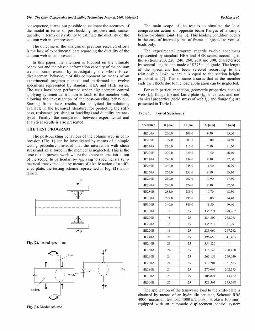
The post-buckling behaviour of the column web in com-pression (Fig. 1) can be investigated by means of a simple testing procedure provided that the interaction with shear stress and axial force in the member is neglected. This is the case of the present work where the above interaction is out of the scope. In particular, by applying to specimens a sym-metrical transverse load by means of a knife action of a stiff-ened plate, the testing scheme represented in Fig. (2) is ob-tained.
Fig. (2). Tested specimen.
Fig. (3). Model scheme.
The main scope of the test is to simulate the local compression action of opposite beam flanges of a simple beam-to-column joint (Fig. 3). This loading condition occurs in the case of internal joints of frames subjected to vertical loads only.
The experimental program regards twelve specimens represented by standard HEA and HEB series, according to the sections 200, 220, 240, 260, 280 and 300, characterised by several lengths and made of S275 steel grade. The length of the specimens has been selected according to the relationship L=4h, where h is equal to the section height, proposed in [7]. This distance assures that at the member ends the effects due to the load application can be neglected.
For each particular section, geometric properties, such as web (tw), flange (tf) and knife-plate (tfb) thickness, and me-chanical properties (yield stress of web fyw and flange fyf) are presented in Table 1.
Table 1. Tested Specimens
Specimen b [mm] H [mm] tw [mm] tf [mm]
HE200A 200,0 200,0 9,50 15,00
HE200B 199,0 203,5 10,00 14,50
HE220A 220,0 215,0 7,50 11,50
HE220B 220,0 220,0 10,50 16,40
HE240A 240,0 234,0 8,30 12,00
HE240B 240,0 245,0 11,50 16,70
HE260A 261,0 253,0 8,10 13,10
HE260B 260,0 262,0 10,90 17,30
HE280A 280,0 274,0 9,30 12,50
HE280B 283,0 285,0 10,70 18,30
HE300A 299,0 295,0 10,00 14,40
HE300B 340,0 340,0 11,50 19,40
HE200A 18 25 335,771 278,262
HE200B 18 25 284,309 272,763
HE220A 18 25 335,712 321,291
HE220B 18 25 283,060 267,262
HE240A 21 25 396,656 341,403
HE240B 21 25 354,829 -
HE260A 24 25 318,143 280,458
HE260B 24 25 265,156 269,039
HE280A 24 25 319,201 331,583
HE280B 24 25 270,667 262,293
HE300A 27 25 306,824 313,452
HE300B 27 25 323,563 275,768
The application of the transverse load to the knife-plate is obtained by means of an hydraulic actuator, Schenck RBS 4000 (maximum test load 4000 kN, piston stroke ± 100 mm), equipped with an automatic displacement control system

Theoretical and Experimental Analysis of Column Web in Compression The Open Construction and Building Technology Journal, 2008, Volume 2 297
guided by means of electric transducers directly located on the specimen. The load process is continuously recorded obtaining the load-displacement curves, which are provided in Figs. (4-5) for every specimen of the considered series ( exp is the total displacement in the web plane due to the deformation of both the specimen and the load transmitting system).
Fig. (4). Load-displacement curves for HEA series.
Fig. (5). Load-displacement curves for HEB series.
EXPERIMENTAL BEHAVIOUR OF SPECIMENS
The experimental program has been performed for mono-tonic displacement histories, so that the initial stiffness, ulti-mate resistance and also the whole post-buckling behaviour are obtained for any tested specimen.
The transducer arrangement detailed in Fig. (6) has been used to measure both the transverse displacements in the plane of the applied load and the web out-of-plane displace-ments occurring during the post-buckling behaviour.
Fig. (6). Transducers arrangement.
Fig. (7). Load system test
In particular, transducers C1, C2, T1 and T2 provide the displacements between the stiffened plates, while transduc-ers C3 and C4 provide the out-of-plane deformation of the web. It can be noted that C1, C2, T1 and T2 transducers fol-low the displacement of the load transmitting stiffened plates, so that the obtained measures include also the defor-mations of the load transmitting system.
Therefore, a preliminary characterization of the load transmitting system has been carried out by means of a monotonic test aimed at the evaluation of its stiffness Ksist. This test has been led under force control until a load level greater than the maximum value of the crushing resistance estimated for the considered specimen series (Fig. 7).
The stiffness value of the load transmitting system (Ksist=940 kN/mm) has been successively used to correct the displacements of the experimental load-displacement curves according to the following analytical expression:
=exp sist
=exp
F
Ksist
(1)
Regarding the experimental behaviour of tested speci-mens, it is characterized by an initial linear response with no perceptible elastic deformation. The leaving from the linear response occurs with the appearance of the first yield line on the web profile and the inflection of the loaded flanges. As far as the controlled displacement increases, a considerable plastic engagement of the web panel adjacent to the loaded flanges occurs with a progressive extension of the yielded zones (Figs. 8-9). The occurrence of the maximum resistance is followed by the complete development of a kinematic mechanism characterising the post-buckling behaviour (Fig. 10). The post-buckling behaviour governs the softening branch of the load-displacement curve.
Fig. (8). Plastic engagement of the web panel.

298 The Open Construction and Building Technology Journal, 2008, Volume 2 De Mita et al.
Fig. (9). Plastic deformation measure.
Fig. (10). Post-buckling kinematic mechanism.
TESTING RESULTS AND COMPARISON WITH
AVAILABLE FORMULATIONS
Starting from the experimental results, a comparison is herein presented with the formulations for predicting the initial stiffness, the ultimate strength and the deformation capacity, available in Eurocode 3 and/or in the technical lit-erature. In particular, three comparisons are separately pre-sented with reference to the initial stiffness, the resistance (crushing or buckling) and the plastic deformation capacity.
It has to be mentioned that the available formulations have been applied considering the measured values of the material mechanical properties.
Initial Stiffness
According to Eurocode 3 formulation, the column web in compression is modelled by means of an extensional spring characterised by the following stiffness:
wc
wc
cwc
d
tBEK = (2)
where twc is the web thickness, dwc is the clear depth of the web and B is the effective width.
In particular, B is given by the following equation [9]:
B = 0,7beff,cwc = 0,7 tfb + 2ab 2 + 5k( ) (3)
where tfb is the beam flange thickness, ab is the throat thick-ness of the beam flange-to-column flange weld and k=tfc+rc for rolled sections, being tfc the column flange thickness and rc the web toe fillet.
Some authors (Tschemmernegg et al.) [11], (Faella et al.) [5-9] have already pointed out that the above formulation overestimates the component stiffness; therefore an alterna-tive formula has been proposed:
B = tfb + 2ab 2 + 2 tfc + rc( ) (4)
With reference to the physical meaning of equation (2), it is useful to note that the testing scheme adopted in the pre-sent experimental work concerns an internal joint, so that, from the deformation point of view, the measured displace-ments are due to both the left and the right connections con-verging in the joint. Therefore, taking into account that equa-tion (2) can be directly applied only for external joints, the system stiffness K is derived as:
cwccwccwcK
2
K
1
K
1
K
1=+= (5)
Considering also the above interpretation, the following empirical equation for characterising the initial stiffness of members under symmetrical transverse compression has been proposed by (Aribert et al.) [12].
2
E
d
ttb0,45K
0,25
wc
wc3fcfc
= (6)
In addition, the same research group has proposed a refinement of the above formulation in a successive work (Aribert and Younes) [13]:
2
E
db
ttb0,95K
0,25
wceff
wc23
fcfc= (7)
The stiffness values obtained by means of equation (2), with the effective widths given by formulations (3) and (4), and by means of equations (6) and (7) are presented in Table 2. The contribution of the beam flange-to-column flange weld is equal to zero, being ab=0 in the experimental model. In order to investigate the accuracy of the mentioned formu-lations, in the same table the experimental values are also presented.
The comparison among the several formulations is quan-titatively provided in Table 3 by means of the evaluation of the ratio between the theoretical and the experimental values. For the above ratio, the mean value and the standard devia-tion are also given.
From Table 3, it can be observed that relationship [4], suggested by (Tschemmernegg et al.) [11] and by (Faella et al.) [5,9] leads to values closest to the experimental ones. It can be noted, moreover, that also the Aribert et al. formu-lations leads to a better prediction than Eurocode formula-tion, confirming its trend in overestimating the initial stiff-ness of the component under examination.
Resistance
The design resistance of the column web in compression is given by the minimum value between the crushing resis-tance and the buckling resistance of the web panel.

Theoretical and Experimental Analysis of Column Web in Compression The Open Construction and Building Technology Journal, 2008, Volume 2 299
Table 2. Stiffness values according to different formulations
Profile 0,7 beff
[mm] bFaella et al. [mm]
Kexp
[kN/mm]
HE200A 133,0 91,0 712
HE200B 131,3 90,0 824
HE220A 120,8 84,0 284
HE220B 137,9 93,8 456
HE240A 133,0 91,0 251
HE240B 133,0 100,4 383
HE260A 147,4 99,2 350
HE260B 162,1 107,6 550
HE280A 145,3 98,0 395
HE280B 165,6 109,6 465
HE300A 162,4 107,8 528
HE300B 179,9 117,8 576
Profile KEC3
[kN/mm]
KFaella et al.
[kN/mm]
KAribert et al. (6)
[kN/mm]
KAribert et al. (7)
[kN/mm]
HE200A 971 665 685 684
HE200B 976 669 670 680
HE220A 598 416 522 503
HE220B 986 671 747 757
HE240A 677 463 554 535
HE240B 929 701 769 782
HE260A 688 463 592 553
HE260B 1014 673 784 771
HE280A 692 467 584 568
HE280B 910 603 808 787
HE300A 788 523 664 638
HE300B 862 565 854 829
The crushing resistance is provided by the yield condi-tion of the web panel zone adjacent to the loaded flange, while the buckling load is given by the well known Winter formula. The crushing resistance value can be obtained by the following relationship [2]:
F
cwc= k
cwc f
yw t
wc b
eff,cwc (8)
where is a factor accounting for shear interaction (equal to 1 for the tested specimen), kcwc is a factor accounting for the influence of the vertical normal stress (equal to 1 for tested specimen), fyw is the yield stress of the column web, twc is the web thickness and beff,cwc is the effective width of the column web in compression.
In particular, beff,cwc is calculated according to the follow-ing equation:
bbeff,cwc = tfb + 2ab 2 + 5(tfc + rc ) (9)
where tfb is the beam flange thickness, tfc is the column flange thickness, rc is the web toe fillet and ab is the throat thickness of the beam flange-to-column flange weld.
The buckling load, instead, is given by:
Fcwc
'= F
cwc
11
0,22F
cwc (10)
where the slenderness is given by:
=b
eff,cwc t
wc f
yw
Fcr
1/2
(11)
and
Fcr=
E twc
3
3 12( ) dwc
(12)
where is the Poisson ratio.
Another interpretation of the effective width of the col-umn web in compression has been provided by (Faella et al.) [5] considering the column flange as a beam elastically sup-ported by springs modelling the restraining action due to the column web. By means of this model, the effective width for buckling resistance is obtained by the following equation:
beff,cwc
* = tfb+ 2a
b2 + 2 �
dwc
bfc
3twc
tfc
�
���
�
���
1/4�
�
��
�
�
��
tfc+ r
c( ) (13)
where � represents a reduction coefficient depending on the actual restraining action provided by the column web
Table 3. Comparison among different formulations
Profile KEC3 /
Kexp
KFaella et al./
Kexp
KAribert et al. (6) /
Kexp
KAribert et al. (7) /
Kexp
HE200A 1,36 0,93 0,96 0,96
HE200B 1,18 0,81 0,81 0,83
HE220A 2,11 1,46 1,84 1,77
HE220B 2,16 1,47 1,64 1,66
HE240A 2,70 1,84 2,21 2,13
HE240B 2,43 1,83 2,01 2,04
HE260A 1,97 1,32 1,69 1,58
HE260B 1,84 1,22 1,43 1,40
HE280A 1,75 1,18 1,48 1,44
HE280B 1,96 1,30 1,74 1,69
HE300A 1,49 0,99 1,26 1,21
HE300B 1,50 0,98 1,48 1,44
Mean 1,87 1,28 1,54 1,51
std. dev. 0,18 0,10 0,15 0,14

300 The Open Construction and Building Technology Journal, 2008, Volume 2 De Mita et al.
which was assumed equal to 0.75 on the basis of available experimental results.
An alternative approach has been proposed by (Aribert et al.) [7] and extended by (Catenazzo and Piluso) [10] to the prediction of the whole softening branch of the load-displacement curve. This approach consists in a yield line model representing the collapse mechanism exhibited during experimental tests. It is characterised by the interaction be-tween flanges and web. In particular, the model provides the collapse load and the equilibrium curve of the mechanism describing the post-buckling behaviour of the column web in compression.
The accuracy of the above methods for evaluating the de-sign resistance of the column web in compression, has been investigated by means of a comparison with the experimental results. The results of such comparison are given in the fol-lowing tables. In particular, Table 4 contains the experimen-tal values of the ultimate resistance, the plastic resistance
corresponding to the knee of the experimental load-displacement curve, obtained by means of a secant stiffness given by //KK
cwccwc,s= (Fig. 11), and the values of the slen-
derness . Table 5 provides the comparison with the predic-tions coming from Eurocode formulation, from Faella et al. approach, and also from the analytical results of the yield line approach [10]. In particular, the predicted ultimate resis-tance has been taken as the minimum value between crush-ing and buckling resistance.
Moreover, for each tested specimen, Table 5 provides both the comparisons with the values of the ultimate resis-tance and with the values of the plastic resistance corre-sponding to the knee of the load-displacement curve.
In addition, the mean value and the standard deviation of the ratio between the theoretical prediction and the experimental value are also given.
It can be noted that the formulation suggested by Faella et al. leads, with respect to Eurocode 3, to a slight improve-ment in the prediction of the ultimate resistance of the col-umn web in compression. A further and more significant improvement is obtained when the yield line approach is applied. However, it is important to underline that Faella et al. approach is aimed at the prediction of the knee of the load-displacement curve (design resistance) rather than the prediction of the ultimate resistance. Conversely, Eurocode 3 relationship was established for the ENV version and based on experimental ultimate resistances whose statistical inter-pretation was made according to Annex Z of ENV-1993.
Table 5. Comparison among different formulation for resis-
tance evaluation
Eurocode 3
Specimen Fcwc,EC3
[kN] ,expp
3EC,cwc
F
F
,expu
3EC,cwc
F
F
HE200A 606,07 0,96 0,75
HE200B 533,08 0,86 0,69
HE220A 386,6 0,86 0,85
HE220B 585,51 0,83 0,74
HE240A 532,86 0,98 0,98
HE240B 775,3 0,77 0,68
HE260A 463,17 0,75 0,75
HE260B 669,08 0,74 0,67
HE280A 555,67 0,82 0,81
HE280B 677,41 0,72 0,66
HE300A 645,92 0,89 0,83
HE300B 860,04 0,87 0,81
mean 0,84 0,77
dev. std. 0,006 0,008
Fig. (11). Experimental resistance.
Table 4. Experimental results concerning resistance
Specimen Fp. exp
[kN]
Fu. exp
[kN] �
HE200A 628,6 812 0,63
HE200B 616,4 768,5 0,56
HE220A 450,3 454 0,82
HE220B 706,8 795,5 0,57
HE240A 546,5 546,5 0,88
HE240B 1007,1 1132,5 0,60
HE260A 616,8 620,5 0,88
HE260B 906 998,5 0,62
HE280A 681,3 684,5 0,80
HE280B 943,7 1020,5 0,69
HE300A 729,2 777,5 0,80
HE300B 987,7 1065,5 0,81

Theoretical and Experimental Analysis of Column Web in Compression The Open Construction and Building Technology Journal, 2008, Volume 2 301
Table 5. Contd….
Faella et al.
Specimen FFaella et al.
[kN] ,expp
.aletFaella
F
F
,expu
.aletFaella
F
F
HE200A 606,07 0,96 0,75
HE200B 533,08 0,86 0,69
HE220A 390,67 0,87 0,86
HE220B 585,51 0,83 0,74
HE240A 539,76 0,99 0,99
HE240B 775,3 0,77 0,68
HE260A 475,01 0,77 0,77
HE260B 669,08 0,74 0,67
HE280A 578,61 0,85 0,85
HE280B 684,94 0,73 0,67
HE300A 663,4 0,91 0,85
HE300B 862,31 0,87 0,81
mean 0,85 0,78
dev. std. 0,006 0,009
Yield line
Specimen Fu
[kN] exp,p
u
F
F
exp,u
u
F
F
HE200A 672 1,07 0,83
HE200B 669,5 1,09 0,87
HE220A 428 0,95 0,94
HE220B 679,5 0,96 0,85
HE240A 560 1,02 1,02
HE240B - - -
HE260A 494,5 0,8 0,80
HE260B 729 0,8 0,73
HE280A 592,5 0,87 0,87
HE280B 718 0,76 0,70
HE300A 683 0,94 0,88
HE300B 915 0,93 0,86
mean - 0,93 0,85
dev. std. - 0,011 0,007
Plastic Deformation Capacity
The plastic deformation capacity of the column web in compression is defined following an approach similar to that used for determining the plastic deformation capacity of steel members, as suggested by Kuhlmann with reference to this joint component (Fig. 12) [14].
With reference to (Fig. 11), Fy is the elastic limit load, Fp is the plastic resistance defined consistently to Eurocode 3
and Fu is the ultimate resistance. The corresponding dis-placements are y, p, and m, respectively. Finally, u is the ultimate displacement defined as the maximum displacement before the resistance of the component falls down the plastic resistance.
The experimental results, according to the above defini-
tions are given in Table 6. From this table, it can be noted
that, in some cases, the ultimate displacement, as previously
defined, has not been attained during experimental tests.
Table 6. Experimental Values
Profile y
[mm]
p
[mm]
m
[mm]
u
[mm]
HE200A 0,56 2,63 8,88 -
HE200B 0,65 2,21 8,61 -
HE220A 0,96 4,54 5,39 5,84
HE220B 0,98 4,68 8,70 18,33
HE240A 1,04 6,61 6,62 -
HE240B 1,57 8,15 14,91 24,48
HE260A 1,14 5,41 6,05 6,33
HE260B 0,91 4,85 8,23 15,33
HE280A 1,03 5,18 5,62 5,99
HE280B 1,31 6,08 9,01 13,04
HE300A 0,83 4,18 6,51 9,54
HE300B 1,07 5,19 8,67 13,16
Regarding the prediction of the plastic deformation ca-pacity of the column web in compression, in the technical literature, to the best Author’s knowledge, there is only one proposal by (Beg et al.) [15] who provided an empirical formulation for evaluating the displacement m correspond-ing to the ultimate resistance. According to (Beg et al.) [15], the column web in compression is modelled by means of the simplified load-displacement relationship presented in Fig. (13).
The plastic deformation capacity is evaluated as the dis-placement level corresponding to the maximum resistance. Obviously, this is a safe side assumption, because the post-buckling behaviour is neglected.
The stable part of the deformation capacity m can be de-termined by means of the following equation:
m=
u d (14)
where d is the clear depth of the web, given by:
d = hc 2 rc 2 tfc (15)
and u can be regarded as the non-dimensional deformation
capacity, evaluated as a function of the axial force and of the
web slenderness d/(tw ), with = 235 / fy . In particular,
Beg et al. suggest the following equations:

302 The Open Construction and Building Technology Journal, 2008, Volume 2 De Mita et al.
u =
18,5 0,75dwctwc
1for
dwctwc
1< 20
5,7 0,11dwctwc
1for 20
dwctwc
1< 33
2,07 for 33dwctwc
1
(16)
where u is provided in percent (%). In addition, (Beg et al.)
[15] provide also a similar relationship to be applied for col-
umns subjected to axial forces.
Table 7 provides the m values obtained by means of
equation (16) for the tested specimens. In addition, the ex-
perimental values are also reported. Finally, the ratios be-
tween the value predicted by means of Beg et al. formulas
and experimental value are also provided with the corre-sponding values of the mean and the standard deviation.
It can be noted that the mean value of this ratio is close to
one with a very small standard deviation, so that it can be
concluded that Beg et al. empirical formula leads to high degree of accuracy.
CONCLUSIONS
The results of an experimental program dealing with the
ultimate behaviour of the column web in compression have
been presented and discussed in this paper. The experimental
results have been compared with the available formulations
for predicting the initial stiffness, the resistance and the plas-tic deformation capacity.
Regarding the initial stiffness, the comparison between experimental and theoretical results shows that the formula-tion of (Faella et al.) [(5-9] leads to values closest to the ex-perimental ones. In addition, the trend of Eurocode 3 formu-lation in overestimating the initial stiffness of such joint component has been confirmed by this experimental pro-gram.
Regarding the resistance, all the available formulations provide safe side results, because they are aimed at providing the plastic resistance, corresponding to the knee of the load-displacement curve, rather than the ultimate resistance.
Finally, regarding the plastic deformation capacity, it has been pointed out that the empirical formula proposed by Beg et al. is able to predict with high degree of accuracy the dis-placement corresponding to the maximum load carrying ca-pacity, but post-buckling behaviour is neglected.
The forthcoming activity will be aimed at the experimen-tal investigation of specimens including the influence of the column axial force. In addition, the setting up of a FEM model will allow the development of a parametric analysis.
REFERENCES
[1] J. P. Jaspart, “General report: session on connections”, Journal of Constructional Steel Research, 55, pp. 69-89, 2000.
[2] EN1993-1-8, Eurocode 3 : Design of steel structures. Part 8: De-sign of joints, Comité Européen de Normalisation, 2005.
[3] Mazzolani F.M., Piluso V. Theory and Design of seismic Resistant Steel Frames, E&FN SPON, 1996 pp. 1-487.
[4] EN1998-1-1,Eurocode 8 : Design of structures for earthquake resistance – Part 1: general rules, seismic actions and rules for
buildings, 2005.
Table 7. Comparison with Beg et al. Formulation
Specimen
yf
235=
wt
d u
m,Beg
[mm]
m,exp
[mm]
m,Beg/
m,exp
HE200A 0,8366 16,860 5,855 7,85 8,88 0,88
HE200B 0,9092 15,234 7,075 9,80 8,61 1,14
HE220A 0,8367 24,861 2,965 4,63 5,39 0,86
HE220B 0,9112 15,804 6,647 10,05 8,70 1,16
HE240A 0,7697 26,297 2,807 4,72 6,62 0,71
HE240B 0,8138 18,122 4,909 8,32 14,91 0,56
HE260A 0,8595 25,684 2,875 5,14 6,05 0,85
HE260B 0,9414 17,483 5,388 9,67 8,23 1,17
HE280A 0,8580 25,189 2,929 5,89 5,62 1,05
HE280B 0,9318 20,100 3,489 6,99 9,01 0,78
HE300A 0,8752 24,247 3,033 6,44 6,51 0,99
HE300B 0,8522 25,223 5,423 13,40 8,67 1,55
mean 0,97
dev. std. 0,06
Fig. (12). Kuhlmann conventional procedure
Fig. (13). Simplified force-displacement diagram.
Theoretical and Experimental Analysis of Column Web in Compression The Open Construction and Building Technology Journal, 2008, Volume 2 303
[5] C. Faella, V. Piluso and G. Rizzano: Structural Steel Semirigid
Connections: Theory, Design and Software, CRC Press, 2000. [6] Aribert J.M. Lachal A.: Etude élasto-plastique par analyse des
contraintes de la compression locale sur l’àme d’un profilé, Con-struction Métallique, vol. 4, pp. 3-28, 1977.
[7] Aribert J.M., Lachal A. Moheissen M.: Interaction du voilement et de la résistance plastique de l’âme d’un profilé laminé soumis à une
double compression locale, Construction Métallique, vol. 2, pp. 3-23, 1990.
[8] Aribert J.M., Moheissen M.: Justification théorique d’une formula-tion nouvelle de la résistance en double compression locale d’un
profilé en présence du voilement, Construction Métallique, vol. 4, pp.26-48, 1991.
[9] C. Faella, V. Piluso and G. Rizzano: “Modelling of the Moment-Rotation Curve of Welded Connections”: Proposals to Improve
Eurocode 3 Annex J, C.T.A., Italian Conference on Steel Construc-tion, Riva del Garda, October 1995.
[10] B. Catenazzo and V. Piluso: “Analisi del comportamento post–critico di colonne soggette a doppia compressione d’anima,
C.T.A.”, Giornate Italiane della Costruzione in Acciaio, Venezia,
Settembre 2001. [11] F. Tschemmernegg and M. Huter: “Classification of beam-to-
column joints”, COST C1 Working Group Meeting, 1993. [12] J. M. Aribert, I. Younes and A. Lachal: “Low-cycle fatigue of steel
sections subject to a transverse concentrated load: experimental in-vestigation and practical formulation”, Eurosteel Coimbra, 2002.
[13] J. M. Aribert and I. Younes: “Modélisation en fatigue oligocyclique des composantes de traction et compression locales d’un assem-
blage métallique soudé et application en résistanc sismique”, Con-struction Métallique, pp. 3-26, 2003.
[14] U. Kuhlmann, J. B. Davison and M. Kattner: “Structural systems and rotation capacity, COST C1”, Control of the semi-rigid behav-
iour of civil engineering structural connections, Liege, pp. 17-19 September 1998.
[15] D. Beg, E. Zupan i and I. Vayas: “On the rotation capacity of moment connections”, Eurosteel Coimbra, 2002.
Received: March 31, 2008 Revised: September 29 2008 Accepted: September 30 2008
© De Mita et al.; Licensee Bentham Open.
This is an open access article licensed under the terms of the Creative Commons Attribution Non-Commercial License (http://creativecommons.org/-
licenses/by-nc/3.0/) which permits unrestricted, non-commercial use, distribution and reproduction in any medium, provided the work is properly cited.