open court yard fire department notes
TRANSCRIPT

ARCHITECTURAL
SHEET INDEX CONSULTANTS PROJECT SUMMARY
ARCHITECT
STRUCTURAL
PLOT PLAN SCALE 1/16"=1'-0"
VICINITY MAP
LEGEND
- 2014 BUILDING ANDSAFETY CODE
- 2013 CBC. 2013 CRC AND2012 1BC
A1 - DATA/INDEXA3.1 - SEMI-SUBTERRANEAN PARKING GARAGE PLANA3.2 - PROPOSED SITE AND FIRST FLOOR PLANA3.3 - PROPOSED SECOND FLOOR PLANA3.4 - PROPOSED THIRD FLOOR PLANA3.5 - PROPOSED LOFT PLANA3.6 - PROPOSED ROOF PLANA3.7 - PROPOSED SETBACK AVERAGING PLANA3.8 - PROPOSED LOT COVERAGE AND
COMMON OPEN SPACE AREA CALC.A4.1 - PROPOSED WEST AND SOUTH ELEVATIONSA4.2 - PROPOSED EAST AND NORTH ELEVATIONSA5.1 - PROPOSED BUILDING SECTIONS
L-1 - PROPOSED LANDSCAPE PLAN
HAMLET ZOHRABIANS AIALICENSE- C-0226713467 OCEANVIEW BLVD. SUITE BGLENDALE, CA. 91208T - 818.236.3619F - 818.236.2171
ABBREVIATIONS
AB ANCHOR BOLT
AC AC08ST9C(AL)
A/C AIR CONDITIONING
ACT ACOUSTICAL TILE
AFF ABOVE FINISH FLOOR
AL ALUMINUM
ALT ALTERNATIVE
ANG ANCHOR, ANCHORAGE
AP AXIS PANEL
APPROX APPROXIMATE
ARCH ARCHITECT(URAL)
ASPH ASPHALT
AT ASPHALT TILE
AUTO AUTOMATIC
BD BOARD
BET BETWEEN
BLDG BUILDLING
BLK BLOCK
BLKG BLOCKING
BOT BOTTOM
BS BOTH SIDES
BW BOTH WAYS
CAB CABINET
CB CATCH BASIN
CEM CEMENT
CFL COUNTERFLASHING
CI CAST IRON
CLG CEILING
CLR CLEAR(ANCE)
COL COLUMN
COMB COMBINATION
COMPO COMPOSITION
CONC CONCRETE
CONST CONSTRUCTION
CONT CONTINUOUS
CPT CARPET
CT CERAMIC TILE
CTR COUNTER
D DRAIN
DEM DEMOLITION
DIAG DIAGONAL
DIAM DIAMETER
DIFF DIFFUSER
DIM DIMENSION
DIV DIVISION
DN DOWN
DR DOOR
DS DOWN SPOUT
DTL DETAIL
DW DRYWALL
DWG DRAWING
EF EXPANSION BOLT
EL ELEVATION
ELEC ELECTRIC(AL)
ELEV ELEVATOR
EMER EMERGENCY
ENCL ENCLOSE(URE)
ENGR ENGINEER
EQ EQUAL
EQUIP EQUIPMENT
EXH EXHAUST
EXIST EXISTING
EXP EXPOSED
EXT EXTERIOR
FBD FIBERBOARD
DF FLOOR DRAWIN
FEC FIRE EXTINGUISHER CABINET
FF FINISHED FLOOR
FIG FIGURE
FIN FINISH(ED)
FIXT FIXTURE
FLG FLASHING
FLR FLOOR(ING)
FLOUR FLUORESCENT
FND FOUNDATION
FOC FACE OF CONCRETE
FR FRAME(D)(ING)
FT FOOT,FEET
FUR FURR(ED)(ING)
FTG FOOTING
GA GAUGE
GD GARBAGE DISPOSAL
GL GLASS,GLAZING
GPBD GYPSUM BOARD
GR GRADE, GRADING
GRN GRANITE
GYP GYPSUM
HB HOSE BIB
HT HEIGHT
HTG HEATING
HVAC HEATING, VENTILATION, AIR
COND.
INSUL INSULATE(D)(TION)
INT INTERIOR
JST JOIST
LAM LAMINATE(D)
LAV LAVATORY
LB LAG BOLT
LH LEFT HAND
LW LIGHT WEIGHT
LWC LIGHT WEIGHT CONCRETE
MAT MATERIAL
MAX MAXIMUM
MECH MECHANIC(AL)
MFR MANUFACTURE(R)
MIN MINIMUM
MISC MISCELLANEOUS
MRB MARBLE
MTFR METAL FURRING
MTL METAL
MULL MULLION
NOM NOMINAL
NIC NOT IN CONTRACT
NTS NOT TO SCALE
OC ON CENTER
OPP OPPOSITE
PG PLATE GLASS
PL PLATE
PLAM PLASTER LAMINATE
PLAS PLASTER
PLYWD PLYWOOD
PNL PANEL
PNT POINT
PT PAINT
PTN PARTITION
PVMT PACEMENT
R RISER
RA RETURN AIR
RAD RADIUS
RD ROOF DRAIN
REF REFERENCE
REFR REFRIGERATOR
REINF REINFORCE(D)(ING)
REQ REQUIRED
RET RETURN
REV REVISION, REVISED
RH RIGHT HAND
RM ROOM
SC SOLID CORE
SD STORM DRAIN
SECT SECTION
SHT SHEET
SIM SIMILAR
SPEC SPECIFICATION(S)
SQ SQUARE
ST STEEL
STD STANDARD
STOR STORAGE
STR STRUCTURE
SUSP SUSPENDED
T TREAD
TC TOP OF CURB
TEL TELEPHONE
TEXT TEXTURED
THK THICK(NESS)
THR THRESHOLD
TOSL TOP OF SLAB
TOST TOP OF STEEL
TOW TOP OF WALL
TOP TOP OF PLATE
TV TELEVISION
TYP TYPICAL
UNO UNLESS NOTED OTHERWISE
VENT VENTILATE(TION)
VERT VERTICAL
VT VINYL TILE
WC WATER CLOSET
WG WIRE GLASS
WM WIRE MESH
WP WATERPROOFING
SMOKE DETECTOR (HARD WIRED W/ BATTERY BACK-UP)
EXHAUST FAN ( 50 CFM )
1/4"- 1/2" MAX. @ FLOOR THRESHOLD
CARBON MONOXIDE ALARM (HARD WIRED W/ BATTERY BACK-UP)
A6.24,8
CONCRETE BLOCK WALL
INTERIOR SIDE OF 2 X 6 @ 16" O.C. PROVIDE R-13
WOOD FRAMED EXTERIOR WALL1" CEMENT PLASTER OVER PAPER BACKED METAL LATH ONTHE EXTERIOR SIDE AND 5/8" TYPE "X" GYPSUM BOARD ON
INSULATION IN STUD SPACE
1-HR RATED WOOD FRAMED FIRE BARRIERTWO LAYERS OF 5/8" TYPE "X" GYPSUM BOARD ON EACH SIDE OF DOUBLE 2X6 @ 16" O.C. WITH SOUND INSULATION IN STUD SPACE TYPICAL FOR ALL WALLS SEPARATING
(ALL CARBON MONOXIDE ALARMS SHALL BE CAPABLE OF SUPPORTING
WHOLE HOUSE VENTILATION FAN (50 CFM)
VISIBLE ALARM NOTIFICATION APPLIANCES PER NFPA 720 AND CHAPTER 11B)
30"x30" ATTIC ACCESS OPENING
ILLUMINATED EXIT SIGN
COMBINATION EMERGENCY LIGHTING & EXIT SIGN
A6.219
APARTMENT UNITS FROM EACH OTHER
WOOD FRAMED INTERIOR WALLONE LAYER OF TYPE "X" GYPSUM BOARD ON EACH SIDE OF 2 X6 @ 16" O.C.PROVIDE R-13 INSULATION IN PLUMBING WALL STUD SPACE
1-HR RATED STEEL FRAMED WALL ONE LAYER OF 5/8" TYPE "X" GYPSUM BOARDON EACH SIDE OF 2 1/2 STEEL STUD @ 24" O.C. TYPICAL FOR ALL GARAGE STORAGE WALLS
11A6.2
1. ADDRESS NUMBERSAPPROVED ADDRESS NUMBERS, BUILDING NUMBERS OR APPROVED BUILDING IDENTIFICATION SHALL BEPLACED IN A POSITION THAT IS PLAINLY LEGIBLE AND VISIBLE FROM THE STREET, ROAD, ALLEY, ANDWALKWAYS GIVING ACCESS TO AND WITHIN THE PROPERTY. THESE NUMBERS SHALL CONTRAST WITH THEIRBACKGROUND. ADDRESS NUMBERS SHALL BE ARABIC NUMERALS OR ALPHABET LETTERS. NUMBERS SHALLBE A MINIMUM OF FOUR (4) INCHES (102 MM) HIGH WITH A MINIMUM STROKE WIDTH OF 0.5 INCH (12.7MM) AND SHALL BE ILLUMINATED IN AN APPROVED MANNER (IF NUMBERS ARE ON THE EXTERIOR). NUMBERHEIGHT AND STROKE WIDTH SHALL BE INCREASED AS NEEDED FOR LEGIBILITY BASED ON VISIBILITY DISTANCE.
2. FIRE SPRINKLERS:PROVIDE A COMPLETE AUTOMATIC FIRE SPRINKLER SYSTEM THROUGHOUT THE ENTIRE HOUSE AND DETACHEDGARAGE INSTALLED IN ACCORDANCE WITH THE RECOMMENDATIONS OF NFPA 13D AND THE REQUIREMENTSOF THE GLENDALE FIRE DEPARTMENT. FIRE SPRINKLER PLANS SHALL BE SUBMITTED WITHIN 30 DAYS OFISSUANCE OF THE BUILDING PERMIT.
3. SMOKE DETECTORS:SMOKE DETECTORS SHALL BE WIRED TO THE BUILDING ELECTRICAL SYSTEM, BE EQUIPPED WITH BATTERYBACKUP, AND EMIT A SIGNAL WHEN BATTERIES ARE LOW. SMOKE ALARMS SHALL BE INTERCONNECTED, SO
THAT THE ACTIVATION OF ONE ALARM WILL ACTIVATE ALL OTHER ALARMS.4. CARBON MONOXIDE DETECTORS:
SHALL BE INSTALLED OUTSIDE OF EACH SEPARATE DWELLING UNIT SLEEPING AREA IN THE IMMEDIATE VICINITYOF THE BEDROOM(S) AND ON EVERY LEVEL OF A DWELLING UNIT INCLUDING BASEMENTS. ALARMS SHALL BEHARDWIRED FROM THE BUILDING POWER SUPPLY AND EQUIPPED WITH BATTERY BACKUP. DETECTORS SHALLMEET U.L. 2034 AND/OR NFPA 720 STANDARDS. 2013 CALIFORNIA RESIDENTIAL CODE CHAPTER 3 SECR315
5. FIRE PERMITS:THE FOLLOWING PERMITS ARE REQUIRED FROM THE FIRE DEPARTMENT:FIRE SPRINKLER
6. REQUIRE FIRE DEPARTMENT INSPECTIONS FOR THIS PROJECT ARE LISTED BELOW. FOR ALL INSPECTIONS CALL818-548-4810FIRE SPRINKLER OVERHEAD/UNDERGROUND ROUGH AND FLUSH (BEFORE COVERING ANY PIPING)FIRE SPRINKLER FINALFIRE PREVENTION BUREAU FINAL (ADDRESS SIGNS, EGRESS, FIRE DEPARTMENT ACCESS, SMOKE DETECTOR,FUEL MODIFICATION, ETC)
FIRE DEPARTMENT NOTES
NOTES:
NOTES:
PROJECT BUILDING CODE DATA:
A SEPARATE APPLICATION AND PERMIT IS REQUIRED FOR:1. RETAINING WALLS OR BLOCK FENCE WALLS2. FIRE SPRINKLER SYSTEM3. ELECTRICAL, MECHANICAL, PLUMBING WORK4. DEMOLITION5. GRADING WORK6. SHORING7. SIGNS8. FIRE ALARM9. GATESNO OAK, BAY OR SYCAMORE TREES ON SITE OR WITHIN20' OF PROPERTYNO EASEMENT ON SITENO PROPOSED OR EXISTING POOL OR SPA ON SITENO SLOPES 3:1 OR STEEPER WITHIN 40' OF PROPOSEDWORK AREA
1. A SMART IRRIGATION CONTROLLER SHALL BE INSTALLED FOR ALLLANDSCAPING
2. THE PROJECT SHALL BE DESIGNED TO ACHIEVE AT LEAST 15% MORE ENERGYEFFICIENCY THAN THE 2008 CALIFORNIA ENERGY EFFICIENCY STANDARDS,TITLE 24, PART 6 (SECTION 22.52.2130.C.1).
3. THE PROJECT SHALL RECYCLE AND/OR SALVAGE THE MINIM AMOUNT OFNON-HAZARDOUS CONSTRUCTION AND DEMOLITION DEBRIS (SECTION22.52.2130 .C.4) AND IN COMPLIANCE WITH REQUIREMENTS SET FORTH BYTHE DEPARTMENT OF PUBLIC WORKS, ENVIRONMENTAL PROGRAMS DIVISION.
4. THE PROJECT SHALL COMPLY WITH THE REQUIREMENT THAT TANK-TYPETOILETS BE HIGH-EFFICIENCY TOILETS (MAXIMUM 1.28 GALLONS/FLUSH)(SECTION 22.52.2130.C.3).
BEST MANAGEMENT PRACTICES (BMPs)LID BMPs SHALL BE INSTALLED AS REQUIRED BY THEDEPARTMENT OF PUBLIC WORKS (DPW) PURSUANT TO THECOUNTY'S "LOW IMPACT DEVELOPMENTS STANDARDSMANUAL," UNLESS MODIFIED OR WAIVED BY DPW.
1. PEDESTRIANS SHALL BE PROTECTED DURING CONSTRUCTION,REMODELING AND DEMOLITION ACTIVITIES AS REQUIRED BY 2013CALIFORNIA BUILDING COD, CHAPTER 33.
2. AS DEFINED IN CHAPTER 11A, ALL REQUIRED CARBON MONOXIDE ALARMSSHALL BE CAPABLE OF SUPPORTING VISIBLE ALARM NOTIFICATIONAPPLIANCES PER NFPA 720 AND CHAPTER 11B.
3. THE CONTRACTOR MUST PROVIDE PUBLIC PROTECTION IN ACCORDANCEWITH CBC SECTION 3306 FOR WORK ON ANY BUILDING AND STRUCTUREADJACENT TO THE PUBLIC WAY. (3306)
2014 GLENDALE BUILDLING & SAFETY CODE (GBC)2013 CALIFORNIA GREEN BUIDLING CODE (CBGC)2013 CALIFORNIA BUILDLING CODE (CBC)2013 CALIFORNIA ELECTRICAL CODE (CEC) , TABLE (T)2013 CALIFORNIA PLUMBING CODE (CPC)2013 CALIFORNIA MECHANICAL CODE (CMC)2013 CALIFORNIA FIRE CODE (CFC)
LOW IMPACT DEVELOPMENT (LID) REQUIREMENTS,CHAPTER 22.52, PART 22.
GREEN BUILDING REQUIREMENTS, Chapter 22.52, Part 20.
EXIT
EXIT
THE PLANS SHALL COMPLYWITH THE FOLLOWING:
RESIDENTIAL UNIT AND RETAIL AREA CONFIGURATION:UNIT NO. LOBBY 101 102 201 202 203 204 205 206 207 301 302 303 304 305 306 307 TOTAL
COMMERCIAL TOTAL RESIDENTIAL
BEDROOMS - - - 2 3 3 2 2 3 3 3 4 4 3 3 4 4
FIRST FLOOR 436 1762 1000 - - - - - - - - - - - - - - 2762 s.f. 436 s.f.
SECOND FLOOR. - - - 1178 1323 1348 1106 1106 1348 1323 - - - - - - - - 8732 s.f.
THIRD FLOOR - - - - - - - - - - 1178 1217 1208 1106 1106 1208 1217 - 8240 s.f.
LOFT 236 212 191 184 184 191 212 - 1410 s.f.
TOTAL 436 1762 1000 1178 1323 1348 1106 1106 1348 1323 1414 1429 1399 1290 1290 1399 1429 2762 s.f. 18818 s.f. 21580 s.f.
PRIVATE OPEN SPACE 332 613 240 40 40 240 649 40 347 364 243 243 416 347 4154
MAX. ALLOWABLE HEIGHT OF SOLID FENCE + GARAGE
MAX. ALLOWABLE TOP OF SOLID FENCE WALL = 1176.5'
LOWEST ADJACENT GROUND LEVEL = 1170'ABOVE ADJACENT GROUND LEVEL = 6.5'
PARKING:
PROPOSED RESIDENTIAL PARKING:
ALLOWABLE LOT COVERAGE = 50% X 18,000 s.f. = 9,000 s.f.
ALLOWABLE FLOOR AREA = 1.2 (18,000) = 21,600 s.f.
PROPOSED LOT COVERAGE = 13,895 s.f. = 77.2%
PERIMETER FENCE WALLS:ZONE = C3-1
TOTAL LOT AREA = 18,000 S.F.
PROJECT DATA:
PROJECT DESCRIPTION:
LEGAL DESCRIPTIONS:
(1178.48 + 1171.84) / 2 = 1175.16GRADE =
OUTDOOR SPACE:
ALLOWABLE SEMI-SUBTERRANEAN GARAGE DECK EL. = 1175.16 + 3 = 1178.16PROPOSED SEMI-SUBTERRANEAN GARAGE DECK EL. = 1178
FLOOR AREA:
PROPOSED RESIDENTIAL FLOOR AREA =18,818 s.f.
PROPOSED COMMERCIAL FLOOR AREA = 2,762 s.f.TOTAL PROPOSED FLOOR AREA =22,580 s.f.
REQUIRED RESIDENTIAL PARKING:
PROPOSED COMMERCIAL PARKING:
HANDICPPED = 1STANDARD = 9
TOTAL = 10
HANDICPPED = 2STANDARD = 37
TOTAL = 39
PERMANENT LANDSCAPED OPEN SPACE:RESIDENTIAL CIRCULATION/EXIT CORRIDOR = 1,000 s.f.
LOT COVERAGE:
PROPOSED
GENERAL OFFICE
REQUIRED PARKINGCOMMERCIAL USE RATIO
2.7 / 1000 s.f.
RETAIL (Sales and services) 4 / 1000 s.f.
Beauty Supply 4 / 1000 s.f.
Nail / Hair Salon 4 / 1000 s.f.
ALLOWABLE NUMBER OF UNITS =18,000 S.F./1,250 S.F. = 14.4 UNITSPROPOSED NUMBER OF UNITS = 14
ALLOWABLE HEIGHT =36 FT. + 5' FOR ROOFS W/ MIN. 3:12 = 41'PROPOSED MAXIMUM BUILDING HEIGHT = 41'
NEW PROPOSED THREE STORY 14-UNITAPARTMENT / CONDOMINIUM OVERSEMI-SUBTERRANEAN PARKING GARAGE W/ FIRSTFLOOR RETAIL AND PARKING STRUCTURE
REQUIRED COMMON OUTDOOR SPACE = 200 s.f./UNIT = 2,800 s.f.PROPOSED COMMON OUTDOOR SPACE = 2,809 s.f. REQUIREDPRIVATE OUTDOOR SPACE = 40 s.f. / UNIT PROPOSED PRIVATEOPEN SPACE = 40 s.f. / UNIT MIN.
APN : 5613-006-004APN : 5613-006-005APN : 5613-006-006
SPARR HEIGHTS LOTS 9 AND LOT 10 BLK 8SPARR HEIGHTS LOTS 11,12 AND LOT 13 BLK 8SPARR HEIGHTS LOT 14 BLK 8
2 CAR/2BR UNIT+2.5 CARS/3BR UNIT+3 CAR/4BRUNIT+0.25/UNIT (GUEST) 2 (3) +2.5 (7) + 3 (4) + 0.25 (14) (GUEST) = 39 SPACES
MIN. OF TOTAL LOT AREA TO BE PERMANENTLY PERMANENTLANDSCAPED OPEN SPACE = 25% (18,000 s.f.)
= 4,500 s.f.PROPOSED PERMANENT LANDSCAPED OPEN SPACE = 4,575 s.f.
SECURITY GATE
OPEN COURTYARD
ALLE
Y
SHEET TITLE:
These drawings and specifications are theproperty and copyright of ZOHRABIANSARCHITECTS AND BUILDERS INC., and shallnot be used on any other work except byagreement with ZOHRABIANS ARCHITECTSAND BUILDERS INC. Written dimensions takeprecedence over scaled dimensions and shallbe verified by the contractor on the job site.Any discrepancy shall be brought to theattention of ZOHRABIANS ARCHITECTS ANDBUILDERS INC. prior to the commencement ofany work.The Preliminary drawing indicates the generalscope of the project in terms of architecturaldesign concept, the dimensions of thebuilding, the major architectural elements andthe type of structural, mechanical, electricalsystems. As scope documents the drawingsdo not necessarily indicate or describe allwork required for full performance andcompletion of the requirements of thecontract documents. On the basis of thegeneral scope indicated or described, thecontractor shall furnish all items required forproper execution and completion of the work.
Zohrabians Architects and Builders, Inc.
3467 Ocean View Blvd. Suite B
Glendale, California 91208
T +1 818.236.3619
F +1 818.236.2171
www.zohrabians.com
LOS ANGELES
STAMP:
BYDATEREVISIONS
DESCRIPTION
A1.1
SHEET TITLE:
These drawings and specifications are theproperty and copyright of ZOHRABIANSARCHITECTS AND BUILDERS INC., and shallnot be used on any other work except byagreement with ZOHRABIANS ARCHITECTSAND BUILDERS INC. Written dimensions takeprecedence over scaled dimensions and shallbe verified by the contractor on the job site.Any discrepancy shall be brought to theattention of ZOHRABIANS ARCHITECTS ANDBUILDERS INC. prior to the commencement ofany work.The Preliminary drawing indicates the generalscope of the project in terms of architecturaldesign concept, the dimensions of thebuilding, the major architectural elements andthe type of structural, mechanical, electricalsystems. As scope documents the drawingsdo not necessarily indicate or describe allwork required for full performance andcompletion of the requirements of thecontract documents. On the basis of thegeneral scope indicated or described, thecontractor shall furnish all items required forproper execution and completion of the work.
Zohrabians Architects and Builders, Inc.
3467 Ocean View Blvd. Suite B
Glendale, California 91208
T +1 818.236.3619
F +1 818.236.2171
www.zohrabians.com
LOS ANGELES
DATA/INDEX
JOB NUMBER
DRAWN BY
SHEET
SCALE
DATE 04.25.18
AS SHOWN
MH
053116
Z O H
R A B
I A N
S
CLIENT:
PROJECT:
Anton Oganesyan3510 N Verdugo Blvd.Glendale, Ca. 91208
Verdugo TerraceLuxury Apartments3510 N Verdugo Blvd.Glendale, Ca. 91208

6
PROPOSED SUBTERRANEAN PARKING PLANSCALE 1/8"=1'-0"
1
2120191817
13
12
11
9
8
7
5
33
4
3
36
32
F.S.=1163
31
2322
8'-6"
2
10'-2" 8'-6" 9'-2" 1'9'-2" 9'-2" 9'-2" 1'8'-6"18'8"5'
8'-6"
10'-6
"1'
18'
9'-7"
8'-6"
1'6'-
6"8"
1
8'1'
1'
62'-8" 24'
8'-6" 11'-6"
24
8'-6"
1'1'
1'1'
8'-6"
8'-6"
8'-6"
8'-6"
9'8'-
6"
10
8'-6"
8'-6"
8'-6"
8'-6"
8'-6"
14
UP
9'9'
1'
10'
5'-11
"24
'
18'
1'
25'
1'25'18'
8'-6"
9'-8"
UP
34
ELEV
35
TRASH
RECYCLE ELEV.MACHINE
20'-2
"
5'
25'-4"
25'-4" 9'
9'
37
2'-10
"6'-
6"
18' 4'-8"
6'-4"
8"
5%
F.S.=1159.25'
1'
15 16
F.S.=1157.45'
5%DN
DN
UP
4"
25
26
29'-1
1"
24" DEEP CONCRETESLAB DEPRATION ABOVEFOR LEVEL LANDSCAPING
GUE
STPA
RKIN
G
GUE
STPA
RKIN
G GUESTPARKING
GUESTPARKING
NO
PARK
ING
23'
26'
24'
A5.12
A5.12
A5.11
A5.11
20%
28
18'
29
30
27
18' 10'-4"
1'8'-
6"8'-
6"9'-
7"
4'2'
6'-3"
4' 2'
9'-7"
9'1'
9'11
'-6"
3'-11
"
38
39
14'5'
10%
TRANSFORMER24'
1163.00' 1163.50'
15'
8'-8"
These drawings and specifications are theproperty and copyright of ZOHRABIANSARCHITECTS AND BUILDERS INC., and shallnot be used on any other work except byagreement with ZOHRABIANS ARCHITECTSAND BUILDERS INC. Written dimensions takeprecedence over scaled dimensions and shallbe verified by the contractor on the job site.Any discrepancy shall be brought to theattention of ZOHRABIANS ARCHITECTS ANDBUILDERS INC. prior to the commencement ofany work.The Preliminary drawing indicates the generalscope of the project in terms of architecturaldesign concept, the dimensions of thebuilding, the major architectural elements andthe type of structural, mechanical, electricalsystems. As scope documents the drawingsdo not necessarily indicate or describe allwork required for full performance andcompletion of the requirements of thecontract documents. On the basis of thegeneral scope indicated or described, thecontractor shall furnish all items required forproper execution and completion of the work.
Zohrabians Architects and Builders, Inc.
3467 Ocean View Blvd. Suite B
Glendale, California 91208
T +1 818.236.3619
F +1 818.236.2171
www.zohrabians.com
LOS ANGELES
STAMP:
BYDATEREVISIONS
DESCRIPTION
A3.1
These drawings and specifications are theproperty and copyright of ZOHRABIANSARCHITECTS AND BUILDERS INC., and shallnot be used on any other work except byagreement with ZOHRABIANS ARCHITECTSAND BUILDERS INC. Written dimensions takeprecedence over scaled dimensions and shallbe verified by the contractor on the job site.Any discrepancy shall be brought to theattention of ZOHRABIANS ARCHITECTS ANDBUILDERS INC. prior to the commencement ofany work.The Preliminary drawing indicates the generalscope of the project in terms of architecturaldesign concept, the dimensions of thebuilding, the major architectural elements andthe type of structural, mechanical, electricalsystems. As scope documents the drawingsdo not necessarily indicate or describe allwork required for full performance andcompletion of the requirements of thecontract documents. On the basis of thegeneral scope indicated or described, thecontractor shall furnish all items required forproper execution and completion of the work.
Zohrabians Architects and Builders, Inc.
3467 Ocean View Blvd. Suite B
Glendale, California 91208
T +1 818.236.3619
F +1 818.236.2171
www.zohrabians.com
LOS ANGELES
JOB NUMBER
DRAWN BY
SHEET
SCALE
DATE
1/8"= 1'- 0"
MH
Z O H
R A B
I A N
S
CLIENT:
PROJECT:
Anton Oganesyan3510 N Verdugo Blvd.Glendale, Ca. 91208
Verdugo TerraceLuxury Apartments3510 N Verdugo Blvd.Glendale, Ca. 91208
04.25.18
053116
SHEET TITLE:
PROPOSED SUBTERRANEANPARKING GARAGE PLAN

PROPOSED SITE AND FIRST FLOOR PLANSCALE 1/8"=1'-0"
1
1177'1178'.69
1171.91'
F.F.=1173.5'
F.F.=1173
F.S.=1173
SECURITY GATE
2800 s.f.
8' 9'-2" 1' 9'-2" 10'-6" 1' 9'-4"
18'
1'
11'
11'
3'
2'
11'-5
"2'-
2"11
'-5"
15'-8
"5'
11'-6
"2'
12'-4
"17
'-2"
4'-3"
1'-6"
3'-6"
21'-10"10'-10"62'-7"
13'-6
"
9'-2"9'-7"
1
18'-6"
21'-5
"
DN
UP
1174.55'
1173.24'
1170.81'
DN
20'-2
"
1' 1'
1167.25'1163.00' 1166.75'
10%20%
16'-9" 10'5'16'-9"5'
DN UP
2'
LOBBYOPEN COURT
YARD
1762 s.f.GENERAL OFFICE / RETAIL
UNIT 101
ELEV.
1167.40'
2 3 4 5
MAIL BOX
21'-4"
4'-8"5'
10'-4
"58
'-6"COMMON
OPEN SPACE
23'-6"23'-8"
148 s.f.
150'
120'
23'-3"
32 s.f.
21 s.f.
LOWEST GRADE @BUILDING=1171.13'
2'4'
954 s.f.GENERAL OFFICE / RETAIL
UNIT 102
4'-4"
11'-6
"2'
12'-4
"
1177.59'
2'1176.43'
1175.3'
1'
5'-2"
6
7
8
9
10
9'-2"
8'-6"
1'8'-
6"8'-
6"10
'-6"
8'-4"
1174.87'
6'
F.F.=1176.5'
92 s.f.
92 s.f.
SECOND FLOORABOVE
1'-6"
5'
5% 10%
5%
15'
F.S.=1173
24'-6"
UP
A5.11
A5.11
A5.12
A5.12
MAX. ALLOWABLE HEIGHT OF SOLID FENCE + GARAGE
REQUIRED PRIVATE OUTDOOR SPACE = 40 s.f. / UNIT
REQUIRED COMMON OUTDOOR SPACE = 200 s.f./UNIT = 2,800 s.f.
PROPOSED PRIVATE OPEN SPACE = 40 s.f. / UNIT MIN.
MAX. ALLOWABLE TOP OF SOLID FENCE WALL = 1176.5'
2 CAR/2BR UNIT+2.5 CARS/3BR UNIT+3 CAR/4BR UNIT+0.25/UNIT (GUEST)
LOWEST ADJACENT GROUND LEVEL = 1170'ABOVE ADJACENT GROUND LEVEL = 6.5'
PARKING:
PROPOSED RESIDENTIAL PARKING:
PROPOSED MAXIMUM BUILDING HEIGHT = 41'
PROPOSED NUMBER OF UNITS = 14
ALLOWABLE HEIGHT = 36 FT. + 5' FOR ROOFS W/ MIN. 3:12 = 41'
ALLOWABLE LOT COVERAGE = 50% X 18,000 s.f. = 9,000 s.f.
ALLOWABLE FLOOR AREA = 1.2 (18,000) = 21,600 s.f.
PROPOSED LOT COVERAGE = 13,895 s.f. = 77.2%
ALLOWABLE NUMBER OF UNITS = 18,000 S.F./1,250 S.F. = 14.4 UNITS
PERIMETER FENCE WALLS:
ZONE = C3-1
TOTAL LOT AREA = 18,000 S.F.
PROJECT DATA:
NEW PROPOSED THREE STORY 14-UNIT APARTMENT / CONDOMINIUM
PROJECT DESCRIPTION:
OVER SEMI-SUBTERRANEAN PARKING GARAGE
LEGAL DESCRIPTIONS:
APN : 5613-006-004
(1178.48 + 1171.84) / 2 = 1175.16GRADE =
OUTDOOR SPACE:
PROPOSED COMMON OUTDOOR SPACE = 2,809 s.f.
ALLOWABLE SEMI-SUBTERRANEAN GARAGE DECK EL. = 1175.16 + 3 = 1178.16PROPOSED SEMI-SUBTERRANEAN GARAGE DECK EL. = 1178
W/ FIRST FLOOR RETAIL AND PARKING STRUCTURE
2 (3) + 2.5 (7) + 3 (4) + 0.25 (14) (GUEST) = 39 SPACES
FLOOR AREA:
PROPOSED RESIDENTIAL FLOOR AREA =18,818 s.f.
PROPOSED COMMERCIAL FLOOR AREA = 2,762 s.f.TOTAL PROPOSED FLOOR AREA =22,580 s.f.
REQUIRED RESIDENTIAL PARKING:
PROPOSED COMMERCIAL PARKING:
SPARR HEIGHTS LOTS 11,12 AND LOT 13 BLK 8SPARR HEIGHTS LOTS 9 AND LOT 10 BLK 8
SPARR HEIGHTS LOT 14 BLK 8
APN : 5613-006-005APN : 5613-006-006
HANDICPPED = 1STANDARD = 9
TOTAL = 10
HANDICPPED = 2STANDARD = 37
TOTAL = 39
MIN. OF TOTAL LOT AREA TO BE PERMANENTLYPERMANENT LANDSCAPED OPEN SPACE = 25% (18,000 s.f.) = 4,500 s.f.
PERMANENT LANDSCAPED OPEN SPACE:
PROPOSED PERMANENT LANDSCAPED OPEN SPACE = 4,575 s.f.
RESIDENTIAL CIRCULATION/EXIT CORRIDOR = 1,000 s.f.
LOT COVERAGE:
25'
18'
2' 4'
18'
2'-9"
1163.50'
10%
F.F.=1173
UP8.6%
6'-11" 36' 6'
1168.05'UPDELIVERIES / MOVING TRECK
6'16
'-10"
20'-2
"
10'
PROPOSED
GENERAL OFFICE
REQUIRED PARKINGCOMMERCIAL USE RATIO
2.7 / 1000 s.f.
RETAIL (Sales and services) 4 / 1000 s.f.
Beauty Supply 4 / 1000 s.f.
Nail / Hair Salon 4 / 1000 s.f.
10' 10'
1'
5%
1167.50'1167.50'
5' 12'-10"
25'
OPEN METALRAILING FENCE
PLASTEREDCONCRETE BLOCKFENCE WALL
6'
165'
18" MAX. TALLPLANTER (TYP.)
OPEN METAL RAILINGFENCE OVER 18" MAX.TALL CONCRETE PLANTER
OPEN METAL RAILINGFENCE OVER 18" MAX.TALL CONCRETE CURB
6'-8"
4'-8"
30'-2
"
18'
1'
5'16'-10"
BBQPICNICTABLE
4'
1176.0
2ST
ART
1171.8
4TC
1171.1
1FL
1171.8
3ST
LT
1175.2
0TX
1174.4
5FL
1174.5
4G
1174.6
6BX
1175.1
6FL
1175.2
1G
1175.5
9BX
1176.5
1TX
1175.7
1FL
1178.4
0FS
1177.1
6FS
1175.9
2FS
1174.6
6FS
1173.3
5FS
1171.9
2FS
1171.2
8CL
F
1170.9
4CL
FCR
1172.7
8NG
1173.0
9FS
1175.6
6FS
1175.3
9FL
1175.8
9FS
1174.9
4FS
1174.4
8FS
1173.1
9FS
1172.9
7FL
1173.6
5FS
1172.6
4FS 117
1.67
FL
1172.2
12.
5X3.
5EM
H
1170.8
3TC
0117
1.07
TC
1170.2
7FL
1171.0
9FS
1169.7
0FS
1168.8
6FL
1169.6
0TC
1169.1
2FS
1168.2
7TC
1167.8
6FS
1167.4
7FL
1168.4
1SS
1166.4
0FL
1167.3
0TC
1166.9
8FS
1166.8
0PP
1167.2
12.
5X3.
5EV
1170.8
1.6
7TW
NG117
0.81
TWNG
1171.5
2TW
NG117
2.18
TWNG
1172.8
3TW
NG117
2.86
TWNG
1173.5
4TW
FS
1172.6
2W
M
1178.4
8TC
1177.7
6FL
1178.6
9SW
1179.0
7FS
TC
1176.7
1F
1176.5
5FL
1-STORY BLDG1-STORY BLDG
2-STORY BLDG
G
DN
TRANSFORMER
PROPOSED TRANSFORMERVAILT BELOW
5'-6"
25'
5'
35'
These drawings and specifications are theproperty and copyright of ZOHRABIANSARCHITECTS AND BUILDERS INC., and shallnot be used on any other work except byagreement with ZOHRABIANS ARCHITECTSAND BUILDERS INC. Written dimensions takeprecedence over scaled dimensions and shallbe verified by the contractor on the job site.Any discrepancy shall be brought to theattention of ZOHRABIANS ARCHITECTS ANDBUILDERS INC. prior to the commencement ofany work.The Preliminary drawing indicates the generalscope of the project in terms of architecturaldesign concept, the dimensions of thebuilding, the major architectural elements andthe type of structural, mechanical, electricalsystems. As scope documents the drawingsdo not necessarily indicate or describe allwork required for full performance andcompletion of the requirements of thecontract documents. On the basis of thegeneral scope indicated or described, thecontractor shall furnish all items required forproper execution and completion of the work.
Zohrabians Architects and Builders, Inc.
3467 Ocean View Blvd. Suite B
Glendale, California 91208
T +1 818.236.3619
F +1 818.236.2171
www.zohrabians.com
LOS ANGELES
STAMP:
BYDATEREVISIONS
DESCRIPTION
A3.2
These drawings and specifications are theproperty and copyright of ZOHRABIANSARCHITECTS AND BUILDERS INC., and shallnot be used on any other work except byagreement with ZOHRABIANS ARCHITECTSAND BUILDERS INC. Written dimensions takeprecedence over scaled dimensions and shallbe verified by the contractor on the job site.Any discrepancy shall be brought to theattention of ZOHRABIANS ARCHITECTS ANDBUILDERS INC. prior to the commencement ofany work.The Preliminary drawing indicates the generalscope of the project in terms of architecturaldesign concept, the dimensions of thebuilding, the major architectural elements andthe type of structural, mechanical, electricalsystems. As scope documents the drawingsdo not necessarily indicate or describe allwork required for full performance andcompletion of the requirements of thecontract documents. On the basis of thegeneral scope indicated or described, thecontractor shall furnish all items required forproper execution and completion of the work.
Zohrabians Architects and Builders, Inc.
3467 Ocean View Blvd. Suite B
Glendale, California 91208
T +1 818.236.3619
F +1 818.236.2171
www.zohrabians.com
LOS ANGELES
JOB NUMBER
DRAWN BY
SHEET
SCALE
DATE
Z O H
R A B
I A N
S
CLIENT:
PROJECT:
Anton Oganesyan3510 N Verdugo Blvd.Glendale, Ca. 91208
Verdugo TerraceLuxury Apartments3510 N Verdugo Blvd.Glendale, Ca. 91208
SHEET TITLE:
PROPOSED SITE AND FIRSTFLOOR PLAN
1/8"= 1'- 0"
MH
04.25.18
053116
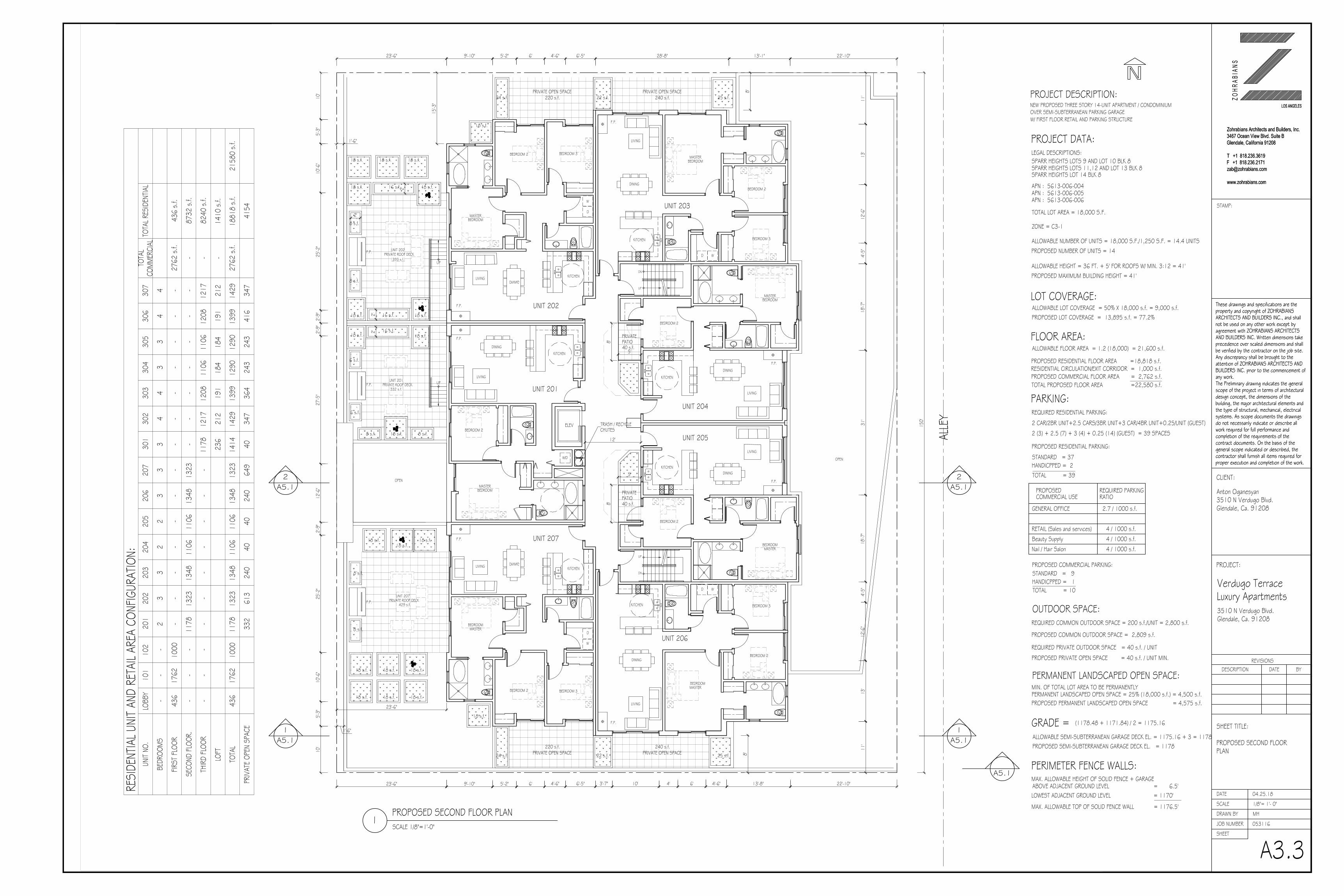
PROPOSED SECOND FLOOR PLANSCALE 1/8"=1'-0"
1
ALLE
Y
150'
13'-1"28'-8"5'-2"9'-10"
10'
10'-6
"25
'-2"
27'-5
"12
'-6"
25'-2
"10
'-6"
22'-10"
8'
13'-8"6'5'-2"9'-10"23'-6" 22'-10"
15'-3
"
10'
5'-3"
4'6'
11'
13'
12'-6
"4'-
5"31
'18
'-7"
4'-5"
12'-6
"11
'13
'18
'-7"
6' 4'-6" 6'-5"
2'-9"
2'-9"
2'-9"
4'-6" 6'-5" 3'-7"
PRIVATE OPEN SPACE240 s.f.
PRIVATE OPEN SPACE220 s.f.
OPEN
UP
UP
F.P.
23'-6"
23'-6"
UNIT 202PRIVATE ROOF DECK
UNIT 201PRIVATE ROOF DECK
UNIT 207PRIVATE ROOF DECK
429 s.f.
393 s.f.
332 s.f.
5'-3"
10' 4'-6"
LIVING
LIVING
12'
KITCHEN
BEDROOM 2
BEDROOMMASTER
ELEV
DINING
MASTERBEDROOM
UNIT 201
BEDROOMMASTER
BEDROOM 3
BEDROOM 2
KITCHEN
MASTERBEDROOM
KITCHEN
BEDROOM 2
KITCHEN
UNIT 202
UNIT 203
F.P.
LIVING
DINING
UNIT 204
DINING
F.P.
F.P.
LIVING
DININGKITCHEN
BEDROOM 2
BEDROOMMASTER
LIVING
BEDROOMMASTER
BEDROOM 3
BEDROOM 2
KITCHEN
MASTERBEDROOM
KITCHEN
UNIT 207
UNIT 206
DINING
UNIT 205
DINING
F.P.
F.P.
F.P.
LIVING
WD
DINING
LIVING
F.P.
PRIVATEPATIO40 s.f.
WD
BEDROOM 2 BEDROOM 3
W
D
BEDROOM 2 BEDROOM 3
W
D
W/D
DN
UP
DN
UP
8'
5'
PRIVATEPATIO40 s.f.
8'
5'
8'PRIVATE OPEN SPACE240 s.f.
PRIVATE OPEN SPACE220 s.f.
F.P.
F.P.
TRASH / RECYCLECHUTES
18 s.f. 18 s.f.18 s.f.
8 s.f.
24 s.f. 22 s.f. 25 s.f.
18 s.f.16 s.f.
18 s.f.
16 s.f.18 s.f. 18 s.f.
18 s.f. 18 s.f.16 s.f.
8 s.f. 8 s.f.
6 s.f.
6 s.f.
8 s.f.
8 s.f.
18 s.f. 18 s.f. 18 s.f.
24 s.f. 22 s.f. 25 s.f.
18 s.f. 18 s.f. 18 s.f.
18 s.f.
18 s.f.
18 s.f. 18 s.f. 18 s.f.
A5.11
A5.11
A5.12
A5.12
OPEN
2'
2'
2'2'
8 s.f.
18 s.f.
A5.1MAX. ALLOWABLE HEIGHT OF SOLID FENCE + GARAGE
REQUIRED PRIVATE OUTDOOR SPACE = 40 s.f. / UNIT
REQUIRED COMMON OUTDOOR SPACE = 200 s.f./UNIT = 2,800 s.f.
PROPOSED PRIVATE OPEN SPACE = 40 s.f. / UNIT MIN.
MAX. ALLOWABLE TOP OF SOLID FENCE WALL = 1176.5'
2 CAR/2BR UNIT+2.5 CARS/3BR UNIT+3 CAR/4BR UNIT+0.25/UNIT (GUEST)
LOWEST ADJACENT GROUND LEVEL = 1170'ABOVE ADJACENT GROUND LEVEL = 6.5'
PARKING:
PROPOSED RESIDENTIAL PARKING:
PROPOSED MAXIMUM BUILDING HEIGHT = 41'
PROPOSED NUMBER OF UNITS = 14
ALLOWABLE HEIGHT = 36 FT. + 5' FOR ROOFS W/ MIN. 3:12 = 41'
ALLOWABLE LOT COVERAGE = 50% X 18,000 s.f. = 9,000 s.f.
ALLOWABLE FLOOR AREA = 1.2 (18,000) = 21,600 s.f.
PROPOSED LOT COVERAGE = 13,895 s.f. = 77.2%
ALLOWABLE NUMBER OF UNITS = 18,000 S.F./1,250 S.F. = 14.4 UNITS
PERIMETER FENCE WALLS:
ZONE = C3-1
TOTAL LOT AREA = 18,000 S.F.
PROJECT DATA:
NEW PROPOSED THREE STORY 14-UNIT APARTMENT / CONDOMINIUM
PROJECT DESCRIPTION:
OVER SEMI-SUBTERRANEAN PARKING GARAGE
LEGAL DESCRIPTIONS:
APN : 5613-006-004
(1178.48 + 1171.84) / 2 = 1175.16GRADE =
OUTDOOR SPACE:
PROPOSED COMMON OUTDOOR SPACE = 2,809 s.f.
ALLOWABLE SEMI-SUBTERRANEAN GARAGE DECK EL. = 1175.16 + 3 = 1178.16PROPOSED SEMI-SUBTERRANEAN GARAGE DECK EL. = 1178
W/ FIRST FLOOR RETAIL AND PARKING STRUCTURE
2 (3) + 2.5 (7) + 3 (4) + 0.25 (14) (GUEST) = 39 SPACES
FLOOR AREA:
PROPOSED RESIDENTIAL FLOOR AREA =18,818 s.f.
PROPOSED COMMERCIAL FLOOR AREA = 2,762 s.f.TOTAL PROPOSED FLOOR AREA =22,580 s.f.
REQUIRED RESIDENTIAL PARKING:
PROPOSED COMMERCIAL PARKING:
SPARR HEIGHTS LOTS 11,12 AND LOT 13 BLK 8SPARR HEIGHTS LOTS 9 AND LOT 10 BLK 8
SPARR HEIGHTS LOT 14 BLK 8
APN : 5613-006-005APN : 5613-006-006
HANDICPPED = 1STANDARD = 9
TOTAL = 10
HANDICPPED = 2STANDARD = 37
TOTAL = 39
MIN. OF TOTAL LOT AREA TO BE PERMANENTLYPERMANENT LANDSCAPED OPEN SPACE = 25% (18,000 s.f.) = 4,500 s.f.
PERMANENT LANDSCAPED OPEN SPACE:
PROPOSED PERMANENT LANDSCAPED OPEN SPACE = 4,575 s.f.
RESIDENTIAL CIRCULATION/EXIT CORRIDOR = 1,000 s.f.
LOT COVERAGE:
PROPOSED
GENERAL OFFICE
REQUIRED PARKINGCOMMERCIAL USE RATIO
2.7 / 1000 s.f.
RETAIL (Sales and services) 4 / 1000 s.f.
Beauty Supply 4 / 1000 s.f.
Nail / Hair Salon 4 / 1000 s.f.
1'-6"
1'-6" R
ESID
ENTIA
L UNI
T AN
D RE
TAIL
AREA
CON
FIGUR
ATIO
N:UN
IT NO
.LO
BBY
101
102
201
202
203
204
205
206
207
301
302
303
304
305
306
307
TOTA
LCO
MM
ERCI
ALTO
TAL R
ESID
ENTIA
L
BEDR
OOM
S-
--
23
32
23
33
44
33
44
FIRST
FLO
OR43
617
6210
00-
--
--
--
--
--
--
-27
62 s
.f.43
6 s.
f.
SECO
ND F
LOOR
.-
--
1178
1323
1348
1106
1106
1348
1323
--
--
--
--
8732
s.f.
THIR
D FL
OOR
--
--
--
--
--
1178
1217
1208
1106
1106
1208
1217
-82
40 s
.f.
LOFT
236
212
191
184
184
191
212
-14
10 s
.f.
TOTA
L43
617
6210
0011
7813
2313
4811
0611
0613
4813
2314
1414
2913
9912
9012
9013
9914
2927
62 s
.f.18
818
s.f.
2158
0 s.
f.
PRIV
ATE
OPEN
SPA
CE33
261
324
040
4024
064
940
347
364
243
243
416
347
4154
These drawings and specifications are theproperty and copyright of ZOHRABIANSARCHITECTS AND BUILDERS INC., and shallnot be used on any other work except byagreement with ZOHRABIANS ARCHITECTSAND BUILDERS INC. Written dimensions takeprecedence over scaled dimensions and shallbe verified by the contractor on the job site.Any discrepancy shall be brought to theattention of ZOHRABIANS ARCHITECTS ANDBUILDERS INC. prior to the commencement ofany work.The Preliminary drawing indicates the generalscope of the project in terms of architecturaldesign concept, the dimensions of thebuilding, the major architectural elements andthe type of structural, mechanical, electricalsystems. As scope documents the drawingsdo not necessarily indicate or describe allwork required for full performance andcompletion of the requirements of thecontract documents. On the basis of thegeneral scope indicated or described, thecontractor shall furnish all items required forproper execution and completion of the work.
Zohrabians Architects and Builders, Inc.
3467 Ocean View Blvd. Suite B
Glendale, California 91208
T +1 818.236.3619
F +1 818.236.2171
www.zohrabians.com
LOS ANGELES
STAMP:
BYDATEREVISIONS
DESCRIPTION
A3.3
These drawings and specifications are theproperty and copyright of ZOHRABIANSARCHITECTS AND BUILDERS INC., and shallnot be used on any other work except byagreement with ZOHRABIANS ARCHITECTSAND BUILDERS INC. Written dimensions takeprecedence over scaled dimensions and shallbe verified by the contractor on the job site.Any discrepancy shall be brought to theattention of ZOHRABIANS ARCHITECTS ANDBUILDERS INC. prior to the commencement ofany work.The Preliminary drawing indicates the generalscope of the project in terms of architecturaldesign concept, the dimensions of thebuilding, the major architectural elements andthe type of structural, mechanical, electricalsystems. As scope documents the drawingsdo not necessarily indicate or describe allwork required for full performance andcompletion of the requirements of thecontract documents. On the basis of thegeneral scope indicated or described, thecontractor shall furnish all items required forproper execution and completion of the work.
Zohrabians Architects and Builders, Inc.
3467 Ocean View Blvd. Suite B
Glendale, California 91208
T +1 818.236.3619
F +1 818.236.2171
www.zohrabians.com
LOS ANGELES
JOB NUMBER
DRAWN BY
SHEET
SCALE
DATE
Z O H
R A B
I A N
S
CLIENT:
PROJECT:
Anton Oganesyan3510 N Verdugo Blvd.Glendale, Ca. 91208
Verdugo TerraceLuxury Apartments3510 N Verdugo Blvd.Glendale, Ca. 91208
SHEET TITLE:
PROPOSED SECOND FLOORPLAN
1/8"= 1'- 0"
MH
04.25.18
053116
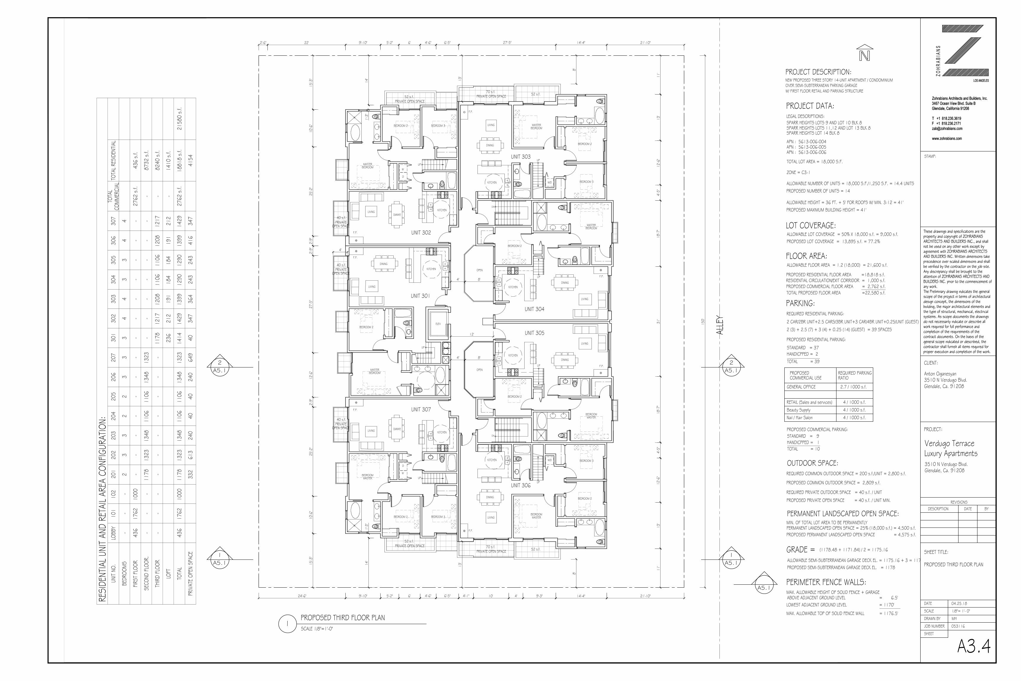
PROPOSED THIRD FLOOR PLANSCALE 1/8"=1'-0"
1
ALLE
Y
150'
14'-4"27'-5"5'-2"9'-10"22'2'-6"
14' 13'
10'-6
"25
'-2"
27'-5
"12
'-6"
25'-2
"10
'-6"
21'-10"
8'
14'-4"9'-3"5'-2"9'-10"24'-6" 21'-10"
15'-3
"15
'-3"
8'
10' 4'6'
11'
13'
12'-6
"4'-
5"31
'18
'-7"
4'-5"
12'-6
"11
'13
'18
'-7"
6' 4'-6" 6'-5"
2'-9"
2'-9"
2'-9"
4'-6" 6'-5" 4'-1"
LIVING
OPEN
OPEN
DN
UP
UP
12'
DININGKITCHEN
BEDROOM 2
BEDROOMMASTER
LIVING
ELEV
DINING
MASTERBEDROOM
UNIT 301
BEDROOM 2
KITCHEN
UNIT 304
F.P.
F.P.
LIVING
DN
UPUP
UP
DININGKITCHEN
BEDROOM 2
BEDROOMMASTER
LIVING
BEDROOMMASTER
BEDROOM 3
BEDROOM 2
BEDROOM 2
KITCHEN
BEDROOM 3
MASTERBEDROOM
W
D
KITCHEN
UNIT 307
UNIT 306
F.P.
LIVING
DINING
W/D
UNIT 305
DINING
F.P.
F.P.
4'
LIVING
UP
BEDROOM 2
KITCHEN
BEDROOM 3
MASTERBEDROOM
W
D
UNIT 302
DINING
F.P.
UP
BEDROOMMASTER
BEDROOM 3
BEDROOM 2
KITCHEN
UNIT 303
F.P.
LIVING
DINING
W/D
1'-3"
14'
13'
1'-3"
4' 8'
4' 8'
A5.11
A5.11
A5.12
A5.12
A5.1MAX. ALLOWABLE HEIGHT OF SOLID FENCE + GARAGE
REQUIRED PRIVATE OUTDOOR SPACE = 40 s.f. / UNIT
REQUIRED COMMON OUTDOOR SPACE = 200 s.f./UNIT = 2,800 s.f.
PROPOSED PRIVATE OPEN SPACE = 40 s.f. / UNIT MIN.
MAX. ALLOWABLE TOP OF SOLID FENCE WALL = 1176.5'
2 CAR/2BR UNIT+2.5 CARS/3BR UNIT+3 CAR/4BR UNIT+0.25/UNIT (GUEST)
LOWEST ADJACENT GROUND LEVEL = 1170'ABOVE ADJACENT GROUND LEVEL = 6.5'
PARKING:
PROPOSED RESIDENTIAL PARKING:
PROPOSED MAXIMUM BUILDING HEIGHT = 41'
PROPOSED NUMBER OF UNITS = 14
ALLOWABLE HEIGHT = 36 FT. + 5' FOR ROOFS W/ MIN. 3:12 = 41'
ALLOWABLE LOT COVERAGE = 50% X 18,000 s.f. = 9,000 s.f.
ALLOWABLE FLOOR AREA = 1.2 (18,000) = 21,600 s.f.
PROPOSED LOT COVERAGE = 13,895 s.f. = 77.2%
ALLOWABLE NUMBER OF UNITS = 18,000 S.F./1,250 S.F. = 14.4 UNITS
PERIMETER FENCE WALLS:
ZONE = C3-1
TOTAL LOT AREA = 18,000 S.F.
PROJECT DATA:
NEW PROPOSED THREE STORY 14-UNIT APARTMENT / CONDOMINIUM
PROJECT DESCRIPTION:
OVER SEMI-SUBTERRANEAN PARKING GARAGE
LEGAL DESCRIPTIONS:
APN : 5613-006-004
(1178.48 + 1171.84) / 2 = 1175.16GRADE =
OUTDOOR SPACE:
PROPOSED COMMON OUTDOOR SPACE = 2,809 s.f.
ALLOWABLE SEMI-SUBTERRANEAN GARAGE DECK EL. = 1175.16 + 3 = 1178.16PROPOSED SEMI-SUBTERRANEAN GARAGE DECK EL. = 1178
W/ FIRST FLOOR RETAIL AND PARKING STRUCTURE
2 (3) + 2.5 (7) + 3 (4) + 0.25 (14) (GUEST) = 39 SPACES
FLOOR AREA:
PROPOSED RESIDENTIAL FLOOR AREA =18,818 s.f.
PROPOSED COMMERCIAL FLOOR AREA = 2,762 s.f.TOTAL PROPOSED FLOOR AREA =22,580 s.f.
REQUIRED RESIDENTIAL PARKING:
PROPOSED COMMERCIAL PARKING:
SPARR HEIGHTS LOTS 11,12 AND LOT 13 BLK 8SPARR HEIGHTS LOTS 9 AND LOT 10 BLK 8
SPARR HEIGHTS LOT 14 BLK 8
APN : 5613-006-005APN : 5613-006-006
HANDICPPED = 1STANDARD = 9
TOTAL = 10
HANDICPPED = 2STANDARD = 37
TOTAL = 39
MIN. OF TOTAL LOT AREA TO BE PERMANENTLYPERMANENT LANDSCAPED OPEN SPACE = 25% (18,000 s.f.) = 4,500 s.f.
PERMANENT LANDSCAPED OPEN SPACE:
PROPOSED PERMANENT LANDSCAPED OPEN SPACE = 4,575 s.f.
RESIDENTIAL CIRCULATION/EXIT CORRIDOR = 1,000 s.f.
LOT COVERAGE:
PROPOSED
GENERAL OFFICE
REQUIRED PARKINGCOMMERCIAL USE RATIO
2.7 / 1000 s.f.
RETAIL (Sales and services) 4 / 1000 s.f.
Beauty Supply 4 / 1000 s.f.
Nail / Hair Salon 4 / 1000 s.f.
PRIVATE OPEN SPACE52 s.f.
PRIVATE40 s.f.
OPEN SPACE
PRIVATE40 s.f.
OPEN SPACE
PRIVATE40 s.f.
OPEN SPACE
PRIVATE OPEN SPACE70 s.f. 52 s.f.
PRIVATE OPEN SPACE52 s.f. PRIVATE OPEN SPACE
70 s.f. 52 s.f.
RES
IDEN
TIAL U
NIT
AND
RETA
IL AR
EA C
ONFIG
URAT
ION:
UNIT
NO.
LOBB
Y10
110
220
120
220
320
420
520
620
730
130
230
330
430
530
630
7TO
TAL
COM
MER
CIAL
TOTA
L RES
IDEN
TIAL
BEDR
OOM
S-
--
23
32
23
33
44
33
44
FIRST
FLO
OR43
617
6210
00-
--
--
--
--
--
--
-27
62 s
.f.43
6 s.
f.
SECO
ND F
LOOR
.-
--
1178
1323
1348
1106
1106
1348
1323
--
--
--
--
8732
s.f.
THIR
D FL
OOR
--
--
--
--
--
1178
1217
1208
1106
1106
1208
1217
-82
40 s
.f.
LOFT
236
212
191
184
184
191
212
-14
10 s
.f.
TOTA
L43
617
6210
0011
7813
2313
4811
0611
0613
4813
2314
1414
2913
9912
9012
9013
9914
2927
62 s
.f.18
818
s.f.
2158
0 s.
f.
PRIV
ATE
OPEN
SPA
CE33
261
324
040
4024
064
940
347
364
243
243
416
347
4154
These drawings and specifications are theproperty and copyright of ZOHRABIANSARCHITECTS AND BUILDERS INC., and shallnot be used on any other work except byagreement with ZOHRABIANS ARCHITECTSAND BUILDERS INC. Written dimensions takeprecedence over scaled dimensions and shallbe verified by the contractor on the job site.Any discrepancy shall be brought to theattention of ZOHRABIANS ARCHITECTS ANDBUILDERS INC. prior to the commencement ofany work.The Preliminary drawing indicates the generalscope of the project in terms of architecturaldesign concept, the dimensions of thebuilding, the major architectural elements andthe type of structural, mechanical, electricalsystems. As scope documents the drawingsdo not necessarily indicate or describe allwork required for full performance andcompletion of the requirements of thecontract documents. On the basis of thegeneral scope indicated or described, thecontractor shall furnish all items required forproper execution and completion of the work.
Zohrabians Architects and Builders, Inc.
3467 Ocean View Blvd. Suite B
Glendale, California 91208
T +1 818.236.3619
F +1 818.236.2171
www.zohrabians.com
LOS ANGELES
STAMP:
BYDATEREVISIONS
DESCRIPTION
A3.4
These drawings and specifications are theproperty and copyright of ZOHRABIANSARCHITECTS AND BUILDERS INC., and shallnot be used on any other work except byagreement with ZOHRABIANS ARCHITECTSAND BUILDERS INC. Written dimensions takeprecedence over scaled dimensions and shallbe verified by the contractor on the job site.Any discrepancy shall be brought to theattention of ZOHRABIANS ARCHITECTS ANDBUILDERS INC. prior to the commencement ofany work.The Preliminary drawing indicates the generalscope of the project in terms of architecturaldesign concept, the dimensions of thebuilding, the major architectural elements andthe type of structural, mechanical, electricalsystems. As scope documents the drawingsdo not necessarily indicate or describe allwork required for full performance andcompletion of the requirements of thecontract documents. On the basis of thegeneral scope indicated or described, thecontractor shall furnish all items required forproper execution and completion of the work.
Zohrabians Architects and Builders, Inc.
3467 Ocean View Blvd. Suite B
Glendale, California 91208
T +1 818.236.3619
F +1 818.236.2171
www.zohrabians.com
LOS ANGELES
JOB NUMBER
DRAWN BY
SHEET
SCALE
DATE
Z O H
R A B
I A N
S
CLIENT:
PROJECT:
Anton Oganesyan3510 N Verdugo Blvd.Glendale, Ca. 91208
Verdugo TerraceLuxury Apartments3510 N Verdugo Blvd.Glendale, Ca. 91208
SHEET TITLE:
PROPOSED THIRD FLOOR PLAN
1/8"= 1'- 0"
MH
04.25.18
053116
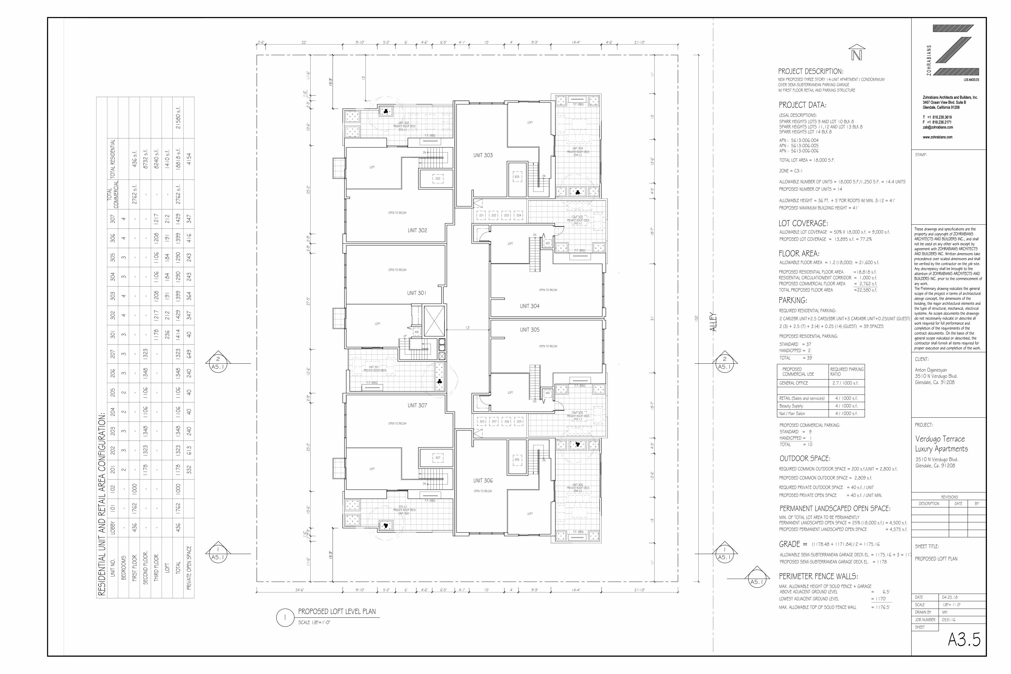
PROPOSED LOFT LEVEL PLANSCALE 1/8"=1'-0"
1
ALLE
Y
150'
14'-4"5'-2"9'-10"22'2'-6"
13'
11'-6
"1'-
6"2'-
3"10
'-6"
25'-2
"27
'-5"
12'-6
"25
'-2"
10'-6
"
21'-10"
14'-4"9'-3"5'-2"9'-10"24'-6" 21'-10"
15'-3
"
11'-6
"1'-
6" 2'-3"
4'6'
11'
13'
12'-6
"4'-
5"31
'18
'-7"
4'-5"
12'-6
"11
'13
'18
'-7"
12'
UNIT 301
UNIT 302
UNIT 303
UNIT 304
UNIT 305
6' 4'-6" 6'-5"
2'-9"
2'-9"
2'-9"
4'-6" 6'-5" 4'-1"
DN
F.P. /BBQ
4'-6"
303
LOFT
201 202 203 204
DN
LOFT W/D
F.P. /BBQ
UNIT 305PRIVATE ROOF DECK
OPEN TO BELOW
243 s.f.
UNIT 304PRIVATE ROOF DECK
294 s.f.
UNIT 306
DN
F.P. /BBQ
306
LOFT
DN
LOFT W/D
F.P. /BBQ
UNIT 305PRIVATE ROOF DECK
OPEN TO BELOW
243 s.f.
UNIT 306PRIVATE ROOF DECK
294 s.f.OPEN TO BELOW
UNIT 302PRIVATE ROOF DECK
15'-3
"
DN
LOFT
F.P. /BBQ
255 s.f.
OPEN TO BELOW
302
UNIT 307
UNIT 302PRIVATE ROOF DECK
DN
LOFT
F.P. /BBQ
255 s.f.
OPEN TO BELOW
307
305 207 206 205
F.P. /BBQ
UNIT 301PRIVATE ROOF DECK
LOFT
OPEN TO BELOW
W/D15
'-3"
15'-3
"
10'
9'-3"4'4'-1" 10'
UP
A5.11
A5.11
A5.12
A5.12
A5.1MAX. ALLOWABLE HEIGHT OF SOLID FENCE + GARAGE
REQUIRED PRIVATE OUTDOOR SPACE = 40 s.f. / UNIT
REQUIRED COMMON OUTDOOR SPACE = 200 s.f./UNIT = 2,800 s.f.
PROPOSED PRIVATE OPEN SPACE = 40 s.f. / UNIT MIN.
MAX. ALLOWABLE TOP OF SOLID FENCE WALL = 1176.5'
2 CAR/2BR UNIT+2.5 CARS/3BR UNIT+3 CAR/4BR UNIT+0.25/UNIT (GUEST)
LOWEST ADJACENT GROUND LEVEL = 1170'ABOVE ADJACENT GROUND LEVEL = 6.5'
PARKING:
PROPOSED RESIDENTIAL PARKING:
PROPOSED MAXIMUM BUILDING HEIGHT = 41'
PROPOSED NUMBER OF UNITS = 14
ALLOWABLE HEIGHT = 36 FT. + 5' FOR ROOFS W/ MIN. 3:12 = 41'
ALLOWABLE LOT COVERAGE = 50% X 18,000 s.f. = 9,000 s.f.
ALLOWABLE FLOOR AREA = 1.2 (18,000) = 21,600 s.f.
PROPOSED LOT COVERAGE = 13,895 s.f. = 77.2%
ALLOWABLE NUMBER OF UNITS = 18,000 S.F./1,250 S.F. = 14.4 UNITS
PERIMETER FENCE WALLS:
ZONE = C3-1
TOTAL LOT AREA = 18,000 S.F.
PROJECT DATA:
NEW PROPOSED THREE STORY 14-UNIT APARTMENT / CONDOMINIUM
PROJECT DESCRIPTION:
OVER SEMI-SUBTERRANEAN PARKING GARAGE
LEGAL DESCRIPTIONS:
APN : 5613-006-004
(1178.48 + 1171.84) / 2 = 1175.16GRADE =
OUTDOOR SPACE:
PROPOSED COMMON OUTDOOR SPACE = 2,809 s.f.
ALLOWABLE SEMI-SUBTERRANEAN GARAGE DECK EL. = 1175.16 + 3 = 1178.16PROPOSED SEMI-SUBTERRANEAN GARAGE DECK EL. = 1178
W/ FIRST FLOOR RETAIL AND PARKING STRUCTURE
2 (3) + 2.5 (7) + 3 (4) + 0.25 (14) (GUEST) = 39 SPACES
FLOOR AREA:
PROPOSED RESIDENTIAL FLOOR AREA =18,818 s.f.
PROPOSED COMMERCIAL FLOOR AREA = 2,762 s.f.TOTAL PROPOSED FLOOR AREA =22,580 s.f.
REQUIRED RESIDENTIAL PARKING:
PROPOSED COMMERCIAL PARKING:
SPARR HEIGHTS LOTS 11,12 AND LOT 13 BLK 8SPARR HEIGHTS LOTS 9 AND LOT 10 BLK 8
SPARR HEIGHTS LOT 14 BLK 8
APN : 5613-006-005APN : 5613-006-006
HANDICPPED = 1STANDARD = 9
TOTAL = 10
HANDICPPED = 2STANDARD = 37
TOTAL = 39
MIN. OF TOTAL LOT AREA TO BE PERMANENTLYPERMANENT LANDSCAPED OPEN SPACE = 25% (18,000 s.f.) = 4,500 s.f.
PERMANENT LANDSCAPED OPEN SPACE:
PROPOSED PERMANENT LANDSCAPED OPEN SPACE = 4,575 s.f.
RESIDENTIAL CIRCULATION/EXIT CORRIDOR = 1,000 s.f.
LOT COVERAGE:
PROPOSED
GENERAL OFFICE
REQUIRED PARKINGCOMMERCIAL USE RATIO
2.7 / 1000 s.f.
RETAIL (Sales and services) 4 / 1000 s.f.
Beauty Supply 4 / 1000 s.f.
Nail / Hair Salon 4 / 1000 s.f.
RES
IDEN
TIAL U
NIT
AND
RETA
IL AR
EA C
ONFIG
URAT
ION:
UNIT
NO.
LOBB
Y10
110
220
120
220
320
420
520
620
730
130
230
330
430
530
630
7TO
TAL
COM
MER
CIAL
TOTA
L RES
IDEN
TIAL
BEDR
OOM
S-
--
23
32
23
33
44
33
44
FIRST
FLO
OR43
617
6210
00-
--
--
--
--
--
--
-27
62 s
.f.43
6 s.
f.
SECO
ND F
LOOR
.-
--
1178
1323
1348
1106
1106
1348
1323
--
--
--
--
8732
s.f.
THIR
D FL
OOR
--
--
--
--
--
1178
1217
1208
1106
1106
1208
1217
-82
40 s
.f.
LOFT
236
212
191
184
184
191
212
-14
10 s
.f.
TOTA
L43
617
6210
0011
7813
2313
4811
0611
0613
4813
2314
1414
2913
9912
9012
9013
9914
2927
62 s
.f.18
818
s.f.
2158
0 s.
f.
PRIV
ATE
OPEN
SPA
CE33
261
324
040
4024
064
940
347
364
243
243
416
347
4154
These drawings and specifications are theproperty and copyright of ZOHRABIANSARCHITECTS AND BUILDERS INC., and shallnot be used on any other work except byagreement with ZOHRABIANS ARCHITECTSAND BUILDERS INC. Written dimensions takeprecedence over scaled dimensions and shallbe verified by the contractor on the job site.Any discrepancy shall be brought to theattention of ZOHRABIANS ARCHITECTS ANDBUILDERS INC. prior to the commencement ofany work.The Preliminary drawing indicates the generalscope of the project in terms of architecturaldesign concept, the dimensions of thebuilding, the major architectural elements andthe type of structural, mechanical, electricalsystems. As scope documents the drawingsdo not necessarily indicate or describe allwork required for full performance andcompletion of the requirements of thecontract documents. On the basis of thegeneral scope indicated or described, thecontractor shall furnish all items required forproper execution and completion of the work.
Zohrabians Architects and Builders, Inc.
3467 Ocean View Blvd. Suite B
Glendale, California 91208
T +1 818.236.3619
F +1 818.236.2171
www.zohrabians.com
LOS ANGELES
STAMP:
BYDATEREVISIONS
DESCRIPTION
A3.5
These drawings and specifications are theproperty and copyright of ZOHRABIANSARCHITECTS AND BUILDERS INC., and shallnot be used on any other work except byagreement with ZOHRABIANS ARCHITECTSAND BUILDERS INC. Written dimensions takeprecedence over scaled dimensions and shallbe verified by the contractor on the job site.Any discrepancy shall be brought to theattention of ZOHRABIANS ARCHITECTS ANDBUILDERS INC. prior to the commencement ofany work.The Preliminary drawing indicates the generalscope of the project in terms of architecturaldesign concept, the dimensions of thebuilding, the major architectural elements andthe type of structural, mechanical, electricalsystems. As scope documents the drawingsdo not necessarily indicate or describe allwork required for full performance andcompletion of the requirements of thecontract documents. On the basis of thegeneral scope indicated or described, thecontractor shall furnish all items required forproper execution and completion of the work.
Zohrabians Architects and Builders, Inc.
3467 Ocean View Blvd. Suite B
Glendale, California 91208
T +1 818.236.3619
F +1 818.236.2171
www.zohrabians.com
LOS ANGELES
JOB NUMBER
DRAWN BY
SHEET
SCALE
DATE
Z O H
R A B
I A N
S
CLIENT:
PROJECT:
Anton Oganesyan3510 N Verdugo Blvd.Glendale, Ca. 91208
Verdugo TerraceLuxury Apartments3510 N Verdugo Blvd.Glendale, Ca. 91208
SHEET TITLE:
PROPOSED LOFT PLAN
1/8"= 1'- 0"
MH
04.25.18
053116

PROPOSED ROOF PLANSCALE 1/8"=1'-0"
1
14'-4"27'-5"31'-11"24'-6"
8'-4"
27'-4
"27
'-5"
12'-6
"30
'-1"
8'-4"
21'-10"
15'-3
"15
'-3"
11'
11'
15'-5
"
12'
2'-9"
2'-9"
201 202 203 204
15'-3
"
302
305 207 206 205
303
TYP.3:12
TYP.3:12
TYP.
3:12
TYP.
3:12
TYP.3:12
TYP.3:12
TYP.
3:12
303
TYP.
3:12
29'-1
1"29
'-11"
TYP.
3:12
TYP.
3:12
TYP.
3:12
TYP.
3:12
TYP.
3:12
TYP.
3:12
TYP.
3:12
TYP.
3:12
TYP.
3:12
TYP.
3:12
TYP.
3:12
TYP.
3:12
TYP.3:12
TYP.3:12
302TYP.
3:12
TYP.
3:12
TYP.3:12
TYP.3:12
TYP.3:12
TYP.3:12
TYP.3:12
TYP.3:12
TYP.
3:12
TYP.
3:12
OPEN
TO
DECK
BEL
OW
18'-8
"18
'-8"
15'-5
"
14'-4"27'-5"31'-11"24'-6" 21'-10"
SOLAR SYSTEM
SOLAR PANELS = 12' x 6'-8" = 80 S.F.
FUTURE ACCESS FOR SOLAR SYSTEM PROVIDE FUTURE ACCESS FOR SOLAR SYSTEM. PROVIDE A MINIMUM OF ONE-INCH ELECTRICAL CONDUIT FROM THE ELECTRICAL SERVICE EQUIPMENT TO AN ACCESSIBLE LOCATIONIN THE ATTIC OR OTHER APPROVED LOCATIONS
REQUIRED AREA FOR FUTURE SOLAR INSTALLATION = 250 S.F. MIN.
TOTAL AREA (4) 80 S.F. = 320 S.F. > 250 S.F.STANDING SEAM METAL ROOFINGOVER 2- 40# ROOFING PAPER OVERPLYWOOD SHEATHING (CLASS "A " MIN.)TYPICAL FOR ALL SLOPED ROOFSPROVIDE 4:12 MIN SLOPE ICC# ESR-3486
L.W. DECK TILES SET IN MORTAROVER WATER PROOF MEMBRANE OVER PLYWOOD SHEATHING TYPICAL FOR ALL ROOF TOP DECKSPROVIDE 1/4":12" MIN. SLOPE ICC# ESR-3486
PROPOSED FUTURE SOLAR PANELS (TYP.) PRIVATE ROOF TOP DECK
BELOW (TYP.)
A5.11
A5.11
A5.12
A5.12
RES
IDEN
TIAL U
NIT
AND
RETA
IL AR
EA C
ONFIG
URAT
ION:
UNIT
NO.
LOBB
Y10
110
220
120
220
320
420
520
620
730
130
230
330
430
530
630
7TO
TAL
COM
MER
CIAL
TOTA
L RES
IDEN
TIAL
BEDR
OOM
S-
--
23
32
23
33
44
33
44
FIRST
FLO
OR43
617
6210
00-
--
--
--
--
--
--
-27
62 s
.f.43
6 s.
f.
SECO
ND F
LOOR
.-
--
1178
1323
1348
1106
1106
1348
1323
--
--
--
--
8732
s.f.
THIR
D FL
OOR
--
--
--
--
--
1178
1217
1208
1106
1106
1208
1217
-82
40 s
.f.
LOFT
236
212
191
184
184
191
212
-14
10 s
.f.
TOTA
L43
617
6210
0011
7813
2313
4811
0611
0613
4813
2314
1414
2913
9912
9012
9013
9914
2927
62 s
.f.18
818
s.f.
2158
0 s.
f.
PRIV
ATE
OPEN
SPA
CE33
261
324
040
4024
064
940
347
364
243
243
416
347
4154
These drawings and specifications are theproperty and copyright of ZOHRABIANSARCHITECTS AND BUILDERS INC., and shallnot be used on any other work except byagreement with ZOHRABIANS ARCHITECTSAND BUILDERS INC. Written dimensions takeprecedence over scaled dimensions and shallbe verified by the contractor on the job site.Any discrepancy shall be brought to theattention of ZOHRABIANS ARCHITECTS ANDBUILDERS INC. prior to the commencement ofany work.The Preliminary drawing indicates the generalscope of the project in terms of architecturaldesign concept, the dimensions of thebuilding, the major architectural elements andthe type of structural, mechanical, electricalsystems. As scope documents the drawingsdo not necessarily indicate or describe allwork required for full performance andcompletion of the requirements of thecontract documents. On the basis of thegeneral scope indicated or described, thecontractor shall furnish all items required forproper execution and completion of the work.
Zohrabians Architects and Builders, Inc.
3467 Ocean View Blvd. Suite B
Glendale, California 91208
T +1 818.236.3619
F +1 818.236.2171
www.zohrabians.com
LOS ANGELES
STAMP:
BYDATEREVISIONS
DESCRIPTION
A3.6
These drawings and specifications are theproperty and copyright of ZOHRABIANSARCHITECTS AND BUILDERS INC., and shallnot be used on any other work except byagreement with ZOHRABIANS ARCHITECTSAND BUILDERS INC. Written dimensions takeprecedence over scaled dimensions and shallbe verified by the contractor on the job site.Any discrepancy shall be brought to theattention of ZOHRABIANS ARCHITECTS ANDBUILDERS INC. prior to the commencement ofany work.The Preliminary drawing indicates the generalscope of the project in terms of architecturaldesign concept, the dimensions of thebuilding, the major architectural elements andthe type of structural, mechanical, electricalsystems. As scope documents the drawingsdo not necessarily indicate or describe allwork required for full performance andcompletion of the requirements of thecontract documents. On the basis of thegeneral scope indicated or described, thecontractor shall furnish all items required forproper execution and completion of the work.
Zohrabians Architects and Builders, Inc.
3467 Ocean View Blvd. Suite B
Glendale, California 91208
T +1 818.236.3619
F +1 818.236.2171
www.zohrabians.com
LOS ANGELES
JOB NUMBER
DRAWN BY
SHEET
SCALE
DATE
Z O H
R A B
I A N
S
CLIENT:
PROJECT:
Anton Oganesyan3510 N Verdugo Blvd.Glendale, Ca. 91208
Verdugo TerraceLuxury Apartments3510 N Verdugo Blvd.Glendale, Ca. 91208
SHEET TITLE:
PROPOSED ROOF PLAN
1/8"= 1'- 0"
MH
04.25.18
053116
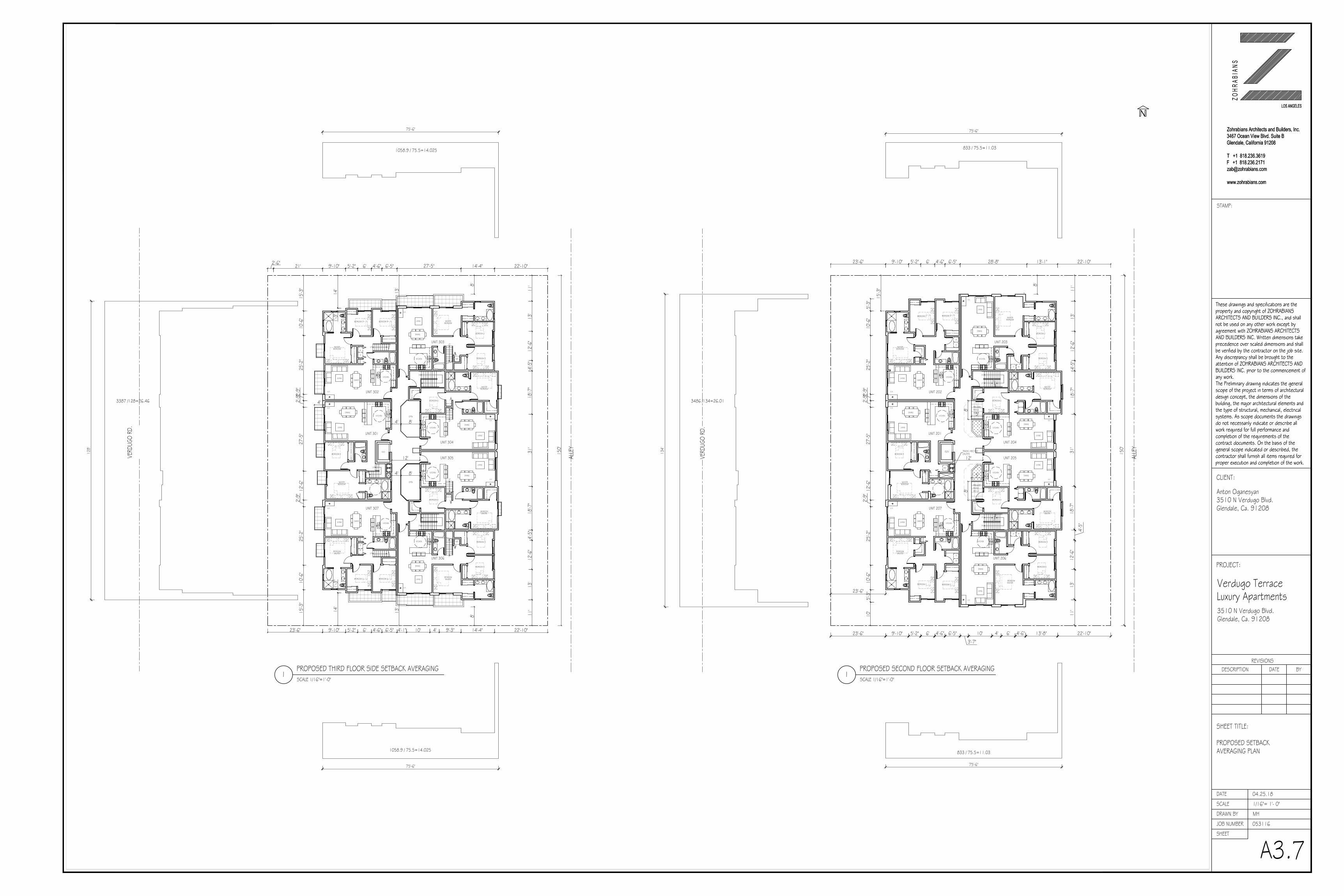
PROPOSED SECOND FLOOR SETBACK AVERAGINGPROPOSED THIRD FLOOR SIDE SETBACK AVERAGINGSCALE 1/16"=1'-0"
1
ALLE
Y
VERD
UGO
RD.
SCALE 1/16"=1'-0"1
3387 /128=26.46
ALLE
Y
150'
VERD
UGO
RD.
1058.9 / 75.5=14.025
75'-6"
833 / 75.5=11.03
75'-6"
833 / 75.5=11.03
75'-6"
3486 /134=26.01
134'
1058.9 / 75.5=14.025
75'-6"
128'
150'
14'-4"27'-5"5'-2"9'-10"21'2'-6"
14'
13'
10'-6
"25
'-2"
27'-5
"12
'-6"
25'-2
"10
'-6"
22'-10"
8'
14'-4"9'-3"5'-2"9'-10"23'-6" 22'-10"
15'-3
"15
'-3"
8'
10' 4'6'
11'
13'
12'-6
"4'-
5"31
'18
'-7"
4'-5"
12'-6
"11
'13
'18
'-7"
6' 4'-6" 6'-5"
2'-9"
2'-9"
2'-9"
4'-6" 6'-5" 4'-1"
LIVING
OPEN
OPEN
DN
UP
UP
12'
DININGKITCHEN
BEDROOM 2
BEDROOMMASTER
LIVING
ELEV
DINING
MASTERBEDROOM
UNIT 301
BEDROOM 2
KITCHEN
UNIT 304
F.P.
F.P.
LIVING
DN
UPUP
UP
DININGKITCHEN
BEDROOM 2
BEDROOMMASTER
LIVING
BEDROOMMASTER
BEDROOM 3
BEDROOM 2
BEDROOM 2
KITCHEN
BEDROOM 3
MASTERBEDROOM
W
D
KITCHEN
UNIT 307
UNIT 306
F.P.
LIVING
DINING
W/D
UNIT 305
DINING
F.P.
F.P.
4'
LIVING
UP
BEDROOM 2
KITCHEN
BEDROOM 3
MASTERBEDROOM
W
D
UNIT 302
DINING
F.P.
UP
BEDROOMMASTER
BEDROOM 3
BEDROOM 2
KITCHEN
UNIT 303
F.P.
LIVING
DINING
W/D
1'-3"
14'
13'
1'-3"
4' 8'
4' 8'
13'-1"28'-8"5'-2"9'-10"
10'-6
"25
'-2"
27'-5
"12
'-6"
25'-2
"10
'-6"
22'-10"
8'
13'-8"6'5'-2"9'-10"23'-6" 22'-10"
15'-3
"
10'
5'-3"
4'6'
11'
13'
12'-6
"4'-
5"31
'18
'-7"
4'-5"
12'-6
"11
'13
'18
'-7"
6' 4'-6" 6'-5"
2'-9"
2'-9"
2'-9"
4'-6" 6'-5"
3'-7"
23'-6"
23'-6"
5'-3"
10' 4'-6"
LIVING
LIVING
12'
KITCHEN
BEDROOM 2
BEDROOMMASTER
ELEV
DINING
MASTERBEDROOM
UNIT 201
BEDROOMMASTER
BEDROOM 3
BEDROOM 2
KITCHEN
MASTERBEDROOM
KITCHEN
BEDROOM 2
KITCHEN
UNIT 202
UNIT 203
F.P.
LIVING
DINING
UNIT 204
DINING
F.P.
F.P.
LIVING
DININGKITCHEN
BEDROOM 2
BEDROOMMASTER
LIVING
BEDROOMMASTER
BEDROOM 3
BEDROOM 2
KITCHEN
MASTERBEDROOM
KITCHEN
UNIT 207
UNIT 206
DINING
UNIT 205
DINING
F.P.
F.P.
F.P.
LIVING
WD
DINING
LIVING
F.P.
PRIVATEPATIO40 s.f.
WD
BEDROOM 2 BEDROOM 3
W
D
BEDROOM 2 BEDROOM 3
W
D
W/D
DN
UP
DN
UP
8'
5'
PRIVATEPATIO40 s.f.
8'
5'
TRASH / RECYCLECHUTES
These drawings and specifications are theproperty and copyright of ZOHRABIANSARCHITECTS AND BUILDERS INC., and shallnot be used on any other work except byagreement with ZOHRABIANS ARCHITECTSAND BUILDERS INC. Written dimensions takeprecedence over scaled dimensions and shallbe verified by the contractor on the job site.Any discrepancy shall be brought to theattention of ZOHRABIANS ARCHITECTS ANDBUILDERS INC. prior to the commencement ofany work.The Preliminary drawing indicates the generalscope of the project in terms of architecturaldesign concept, the dimensions of thebuilding, the major architectural elements andthe type of structural, mechanical, electricalsystems. As scope documents the drawingsdo not necessarily indicate or describe allwork required for full performance andcompletion of the requirements of thecontract documents. On the basis of thegeneral scope indicated or described, thecontractor shall furnish all items required forproper execution and completion of the work.
Zohrabians Architects and Builders, Inc.
3467 Ocean View Blvd. Suite B
Glendale, California 91208
T +1 818.236.3619
F +1 818.236.2171
www.zohrabians.com
LOS ANGELES
STAMP:
BYDATEREVISIONS
DESCRIPTION
A3.7
These drawings and specifications are theproperty and copyright of ZOHRABIANSARCHITECTS AND BUILDERS INC., and shallnot be used on any other work except byagreement with ZOHRABIANS ARCHITECTSAND BUILDERS INC. Written dimensions takeprecedence over scaled dimensions and shallbe verified by the contractor on the job site.Any discrepancy shall be brought to theattention of ZOHRABIANS ARCHITECTS ANDBUILDERS INC. prior to the commencement ofany work.The Preliminary drawing indicates the generalscope of the project in terms of architecturaldesign concept, the dimensions of thebuilding, the major architectural elements andthe type of structural, mechanical, electricalsystems. As scope documents the drawingsdo not necessarily indicate or describe allwork required for full performance andcompletion of the requirements of thecontract documents. On the basis of thegeneral scope indicated or described, thecontractor shall furnish all items required forproper execution and completion of the work.
Zohrabians Architects and Builders, Inc.
3467 Ocean View Blvd. Suite B
Glendale, California 91208
T +1 818.236.3619
F +1 818.236.2171
www.zohrabians.com
LOS ANGELES
JOB NUMBER
DRAWN BY
SHEET
SCALE
DATE
Z O H
R A B
I A N
S
CLIENT:
PROJECT:
Anton Oganesyan3510 N Verdugo Blvd.Glendale, Ca. 91208
Verdugo TerraceLuxury Apartments3510 N Verdugo Blvd.Glendale, Ca. 91208
SHEET TITLE:
PROPOSED SETBACKAVERAGING PLAN
1/16"= 1'- 0"
MH
04.25.18
053116
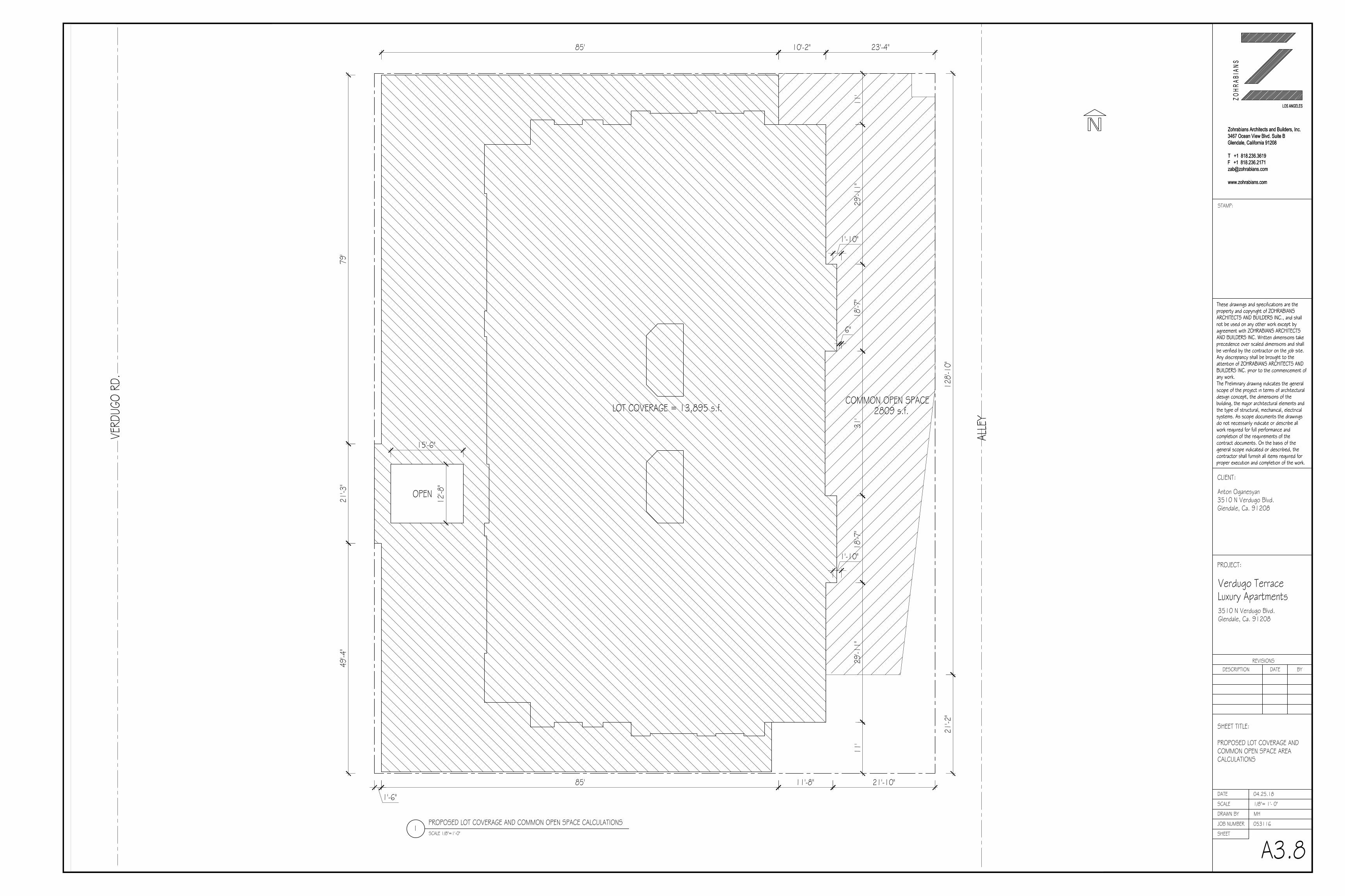
PROPOSED LOT COVERAGE AND COMMON OPEN SPACE CALCULATIONSSCALE 1/8"=1'-0"
1
ALLE
Y
VERD
UGO
RD.
11'
29'-1
1"31
'18
'-7"
29'-1
1"11
'18
'-7"
LOT COVERAGE = 13,895 s.f. 2809 s.f.
128'-
10"
21'-2
"
21'-10"
COMMON OPEN SPACE
12'-8
"
10'-2"
11'-8"
1'-10"
6"
1'-10"
85'
1'-6"
49'-4
"21
'-3"
79'
15'-6"
85' 23'-4"
OPEN
These drawings and specifications are theproperty and copyright of ZOHRABIANSARCHITECTS AND BUILDERS INC., and shallnot be used on any other work except byagreement with ZOHRABIANS ARCHITECTSAND BUILDERS INC. Written dimensions takeprecedence over scaled dimensions and shallbe verified by the contractor on the job site.Any discrepancy shall be brought to theattention of ZOHRABIANS ARCHITECTS ANDBUILDERS INC. prior to the commencement ofany work.The Preliminary drawing indicates the generalscope of the project in terms of architecturaldesign concept, the dimensions of thebuilding, the major architectural elements andthe type of structural, mechanical, electricalsystems. As scope documents the drawingsdo not necessarily indicate or describe allwork required for full performance andcompletion of the requirements of thecontract documents. On the basis of thegeneral scope indicated or described, thecontractor shall furnish all items required forproper execution and completion of the work.
Zohrabians Architects and Builders, Inc.
3467 Ocean View Blvd. Suite B
Glendale, California 91208
T +1 818.236.3619
F +1 818.236.2171
www.zohrabians.com
LOS ANGELES
STAMP:
BYDATEREVISIONS
DESCRIPTION
A3.8
These drawings and specifications are theproperty and copyright of ZOHRABIANSARCHITECTS AND BUILDERS INC., and shallnot be used on any other work except byagreement with ZOHRABIANS ARCHITECTSAND BUILDERS INC. Written dimensions takeprecedence over scaled dimensions and shallbe verified by the contractor on the job site.Any discrepancy shall be brought to theattention of ZOHRABIANS ARCHITECTS ANDBUILDERS INC. prior to the commencement ofany work.The Preliminary drawing indicates the generalscope of the project in terms of architecturaldesign concept, the dimensions of thebuilding, the major architectural elements andthe type of structural, mechanical, electricalsystems. As scope documents the drawingsdo not necessarily indicate or describe allwork required for full performance andcompletion of the requirements of thecontract documents. On the basis of thegeneral scope indicated or described, thecontractor shall furnish all items required forproper execution and completion of the work.
Zohrabians Architects and Builders, Inc.
3467 Ocean View Blvd. Suite B
Glendale, California 91208
T +1 818.236.3619
F +1 818.236.2171
www.zohrabians.com
LOS ANGELES
JOB NUMBER
DRAWN BY
SHEET
SCALE
DATE
Z O H
R A B
I A N
S
CLIENT:
PROJECT:
Anton Oganesyan3510 N Verdugo Blvd.Glendale, Ca. 91208
Verdugo TerraceLuxury Apartments3510 N Verdugo Blvd.Glendale, Ca. 91208
SHEET TITLE:
PROPOSED LOT COVERAGE ANDCOMMON OPEN SPACE AREACALCULATIONS
1/8"= 1'- 0"
MH
04.25.18
053116

1PROPOSED BUILDING WEST ELEVATIONSCALE 1/8"=1'-0"
PL
PL
1'
LOFT LEVEL = 1202
3RD FLOOR = 1193
DECK ABOVE RETAIL = 1186.5
6'-8"
4'1'
34'-3
" 8'1'
5'-6"
8'-7"
LOFT LEVEL = 1202
3RD FLOOR = 1193
1ST FLOOR = 1173'
2ND FLOOR = 1182.5
6'-8"
GRADE = 1175.16
4'1'
8'1'
9'1'
8'-6"
FINISH KEY NOTES:
4 3
2
1. 1" SMOOTH FINISHED CEMENT PLASTER OVER PAPER BACKEDMETAL LATH OVER PLYWOOD SHEATHING ON EXTERIOR SIDE OF2X6 @ 16" O.C. AND A LAYER OF 5/8" GYPSUM BOARD ON THEINTERIOR SIDE. PROVIDE R-13 INSULATION IN STUD SPACECOLOR: WHITE
2. STONE TILES CEMENTED OVER PAPER BACKED METAL LATH OVERPLYWOOD SHEATHING ON EXTERIOR SIDE OF 2X6 @ 16" O.C.AND A LAYER OF 5/8" TYPE "X" GYPSUM BOARD ON THE INTERIORSIDE. PROVIDE R-13 INSULATION IN STUD SPACECOLOR: DARK BROWN
3. HARDIEPLANK LAP SIDING WIDTH 8.25", EXPOSURE 7"COLOR: DARK GREY
4. STANDING SEAM METAL ROOF COVERING COLOR: TO MATCH WINDOW FRAME
5. PRE-PAINTED METAL GUTTER AND DOWN SPOUTCOLOR: DARK BRONZE
6. PAINTED METAL RAILING COLOR: DARK BRONZE
7. PAINTED METAL CHIMNEY CAPCOLOR: DARK BRONZE
8. FIBERGLASS CLAD WOOD FRAMED DUAL GLAZED WINDOWCOLOR: DARK BRONZE
9. FIBERGLASS CLAD WOOD FRAMED DUAL GLAZED DOORCOLOR: DARK BRONZE
10. ANODIZED ALUMINUM CLAD COLOR: MATCH WINDOW FRAMES
11. ANODIZED ALUMINUM STOREFRONT COLOR: DARK BRONZE
12. ANODIZED ALUMINUM STOREFRONT DOOR COLOR: DARK BRONZE
13. PRE-PAINTED SWINGING METAL GATE COLOR: DARK BRONZE
4'
RETAIL FLOOR = 1186.5
8
8
6
2 12121181
2 12 11 2 1211 11 1
1010
2PROPOSED BUILDING SOUTH ELEVATIONSCALE 1/8"=1'-0"
PL
PL
2
8
6LOFT LEVEL = 1202
3RD FLOOR = 1193
1ST FLOOR = 1173'
2ND FLOOR = 1182.5
6'-8"
GRADE = 1175.16
4'1'
8'1'
9'1'
8'-6"
4'
LOFT LEVEL = 1202
3RD FLOOR = 1193
1ST FLOOR = 1173'
2ND FLOOR = 1182.5
6'-8"
4'1'
8'1'
9'1'
8'-6"
4'
1'-10
"
4 3 69 101
1178.69'
LOWST GRADE @ BUILDING = 1170.13
1'-10
"
LOWST GRADE @ BUILDING = 1170.13
1171.91
LOWST GRADE @ BUILDING = 1170.13
41'
LOWST GRADE @ BUILDING = 1170.13
1'-10
"1170.81'
41'
41'
T.O.R. = 1212.67 T.O.R. = 1212.67
41'
T.O.R. = 1212.67T.O.R. = 1212.67
These drawings and specifications are theproperty and copyright of ZOHRABIANSARCHITECTS AND BUILDERS INC., and shallnot be used on any other work except byagreement with ZOHRABIANS ARCHITECTSAND BUILDERS INC. Written dimensions takeprecedence over scaled dimensions and shallbe verified by the contractor on the job site.Any discrepancy shall be brought to theattention of ZOHRABIANS ARCHITECTS ANDBUILDERS INC. prior to the commencement ofany work.The Preliminary drawing indicates the generalscope of the project in terms of architecturaldesign concept, the dimensions of thebuilding, the major architectural elements andthe type of structural, mechanical, electricalsystems. As scope documents the drawingsdo not necessarily indicate or describe allwork required for full performance andcompletion of the requirements of thecontract documents. On the basis of thegeneral scope indicated or described, thecontractor shall furnish all items required forproper execution and completion of the work.
Zohrabians Architects and Builders, Inc.
3467 Ocean View Blvd. Suite B
Glendale, California 91208
T +1 818.236.3619
F +1 818.236.2171
www.zohrabians.com
LOS ANGELES
STAMP:
BYDATEREVISIONS
DESCRIPTION
A4.1
These drawings and specifications are theproperty and copyright of ZOHRABIANSARCHITECTS AND BUILDERS INC., and shallnot be used on any other work except byagreement with ZOHRABIANS ARCHITECTSAND BUILDERS INC. Written dimensions takeprecedence over scaled dimensions and shallbe verified by the contractor on the job site.Any discrepancy shall be brought to theattention of ZOHRABIANS ARCHITECTS ANDBUILDERS INC. prior to the commencement ofany work.The Preliminary drawing indicates the generalscope of the project in terms of architecturaldesign concept, the dimensions of thebuilding, the major architectural elements andthe type of structural, mechanical, electricalsystems. As scope documents the drawingsdo not necessarily indicate or describe allwork required for full performance andcompletion of the requirements of thecontract documents. On the basis of thegeneral scope indicated or described, thecontractor shall furnish all items required forproper execution and completion of the work.
Zohrabians Architects and Builders, Inc.
3467 Ocean View Blvd. Suite B
Glendale, California 91208
T +1 818.236.3619
F +1 818.236.2171
www.zohrabians.com
LOS ANGELES
JOB NUMBER
DRAWN BY
SHEET
SCALE
DATE
Z O H
R A B
I A N
S
CLIENT:
PROJECT:
Anton Oganesyan3510 N Verdugo Blvd.Glendale, Ca. 91208
Verdugo TerraceLuxury Apartments3510 N Verdugo Blvd.Glendale, Ca. 91208
SHEET TITLE:
PROPOSED BUILDINGWEST AND SOUTH ELEVATIONS
1/8"= 1'- 0"
MH
04.25.18
053116

2PROPOSED BUILDING NORTH ELEVATIONSCALE 1/8"=1'-0"
FINISH KEY NOTES:1. 1" SMOOTH FINISHED CEMENT PLASTER OVER PAPER BACKED
METAL LATH OVER PLYWOOD SHEATHING ON EXTERIOR SIDE OF2X6 @ 16" O.C. AND A LAYER OF 5/8" GYPSUM BOARD ON THEINTERIOR SIDE. PROVIDE R-13 INSULATION IN STUD SPACECOLOR: WHITE
2. STONE TILES CEMENTED OVER PAPER BACKED METAL LATH OVERPLYWOOD SHEATHING ON EXTERIOR SIDE OF 2X6 @ 16" O.C.AND A LAYER OF 5/8" TYPE "X" GYPSUM BOARD ON THE INTERIORSIDE. PROVIDE R-13 INSULATION IN STUD SPACECOLOR: DARK BROWN
3. HARDIEPLANK LAP SIDING WIDTH 8.25", EXPOSURE 7"COLOR: DARK GREY
4. STANDING SEAM METAL ROOF COVERING COLOR: TO MATCH WINDOW FRAME
5. PRE-PAINTED METAL GUTTER AND DOWN SPOUTCOLOR: DARK BRONZE
6. PAINTED METAL RAILING COLOR: DARK BRONZE
7. PAINTED METAL CHIMNEY CAPCOLOR: DARK BRONZE
8. FIBERGLASS CLAD WOOD FRAMED DUAL GLAZED WINDOWCOLOR: DARK BRONZE
9. FIBERGLASS CLAD WOOD FRAMED DUAL GLAZED DOORCOLOR: DARK BRONZE
10. ANODIZED ALUMINUM CLAD COLOR: MATCH WINDOW FRAMES
11. ANODIZED ALUMINUM STOREFRONT COLOR: DARK BRONZE
12. ANODIZED ALUMINUM STOREFRONT DOOR COLOR: DARK BRONZE
13. PRE-PAINTED SWINGING METAL GATE COLOR: DARK BRONZE
PL
PL
2
8
6LOFT LEVEL = 1202
3RD FLOOR = 1193
2ND FLOOR = 1182.5
6'-8"
4'1'
35'-2
" 8'1'
9'1'
4'-6"
LOFT LEVEL = 1202
3RD FLOOR = 1193
2ND FLOOR = 1182.5
6'-8"
4'1'
33'-6
"8'1'
9'1'
2'-10
"
436 910 1
1177'
1178.69'
1PROPOSED BUILDING EAST ELEVATIONSCALE 1/8"=1'-0"
PL PL
1'
T.O.R. = 1212.67
LOFT LEVEL = 1202
3RD FLOOR = 1193
DECK ABOVE RETAIL = 1186.5
6'-8"
4'1'
34'-4
"8'1'
5'-6"
8'-7"
LOFT LEVEL = 1202
3RD FLOOR = 1193
1ST FLOOR = 1173'
2ND FLOOR = 1182.5
6'-8"
GRADE = 1175.16
4'1'
8'1'
9'1'
8'-6"
4'
RETAIL FLOOR = 1186.5
6'-6" 6'-
6"
6'-6" 6'-
6"
43 8 610 21 9
83 6 810 21 6113LOWST GRADE @ BUILDING = 1171.13
41'
1'-10
"
LOWST GRADE @ BUILDING = 1171.13
41'
1177'
6'-6"
66
T.O.R. = 1212.67
LOWST GRADE @ BUILDING = 1171.13
41'
T.O.R. = 1212.67
LOWST GRADE @ BUILDING = 1171.13
41'
T.O.R. = 1212.67
These drawings and specifications are theproperty and copyright of ZOHRABIANSARCHITECTS AND BUILDERS INC., and shallnot be used on any other work except byagreement with ZOHRABIANS ARCHITECTSAND BUILDERS INC. Written dimensions takeprecedence over scaled dimensions and shallbe verified by the contractor on the job site.Any discrepancy shall be brought to theattention of ZOHRABIANS ARCHITECTS ANDBUILDERS INC. prior to the commencement ofany work.The Preliminary drawing indicates the generalscope of the project in terms of architecturaldesign concept, the dimensions of thebuilding, the major architectural elements andthe type of structural, mechanical, electricalsystems. As scope documents the drawingsdo not necessarily indicate or describe allwork required for full performance andcompletion of the requirements of thecontract documents. On the basis of thegeneral scope indicated or described, thecontractor shall furnish all items required forproper execution and completion of the work.
Zohrabians Architects and Builders, Inc.
3467 Ocean View Blvd. Suite B
Glendale, California 91208
T +1 818.236.3619
F +1 818.236.2171
www.zohrabians.com
LOS ANGELES
STAMP:
BYDATEREVISIONS
DESCRIPTION
A4.2
These drawings and specifications are theproperty and copyright of ZOHRABIANSARCHITECTS AND BUILDERS INC., and shallnot be used on any other work except byagreement with ZOHRABIANS ARCHITECTSAND BUILDERS INC. Written dimensions takeprecedence over scaled dimensions and shallbe verified by the contractor on the job site.Any discrepancy shall be brought to theattention of ZOHRABIANS ARCHITECTS ANDBUILDERS INC. prior to the commencement ofany work.The Preliminary drawing indicates the generalscope of the project in terms of architecturaldesign concept, the dimensions of thebuilding, the major architectural elements andthe type of structural, mechanical, electricalsystems. As scope documents the drawingsdo not necessarily indicate or describe allwork required for full performance andcompletion of the requirements of thecontract documents. On the basis of thegeneral scope indicated or described, thecontractor shall furnish all items required forproper execution and completion of the work.
Zohrabians Architects and Builders, Inc.
3467 Ocean View Blvd. Suite B
Glendale, California 91208
T +1 818.236.3619
F +1 818.236.2171
www.zohrabians.com
LOS ANGELES
JOB NUMBER
DRAWN BY
SHEET
SCALE
DATE
Z O H
R A B
I A N
S
CLIENT:
PROJECT:
Anton Oganesyan3510 N Verdugo Blvd.Glendale, Ca. 91208
Verdugo TerraceLuxury Apartments3510 N Verdugo Blvd.Glendale, Ca. 91208
SHEET TITLE:
PROPOSED BUILDINGEAST AND NORTH ELEVATIONS
1/8"= 1'- 0"
MH
04.25.18
053116

(665 + 404)/2 = 534.5 s.f.534.5 s.f. (150 ft.) = 80,175 s.f.80,175 s.f. / 27 = 2,969.4 c.y.
2PROPOSED BUILDING CROSS SECTIONSCALE 1/8"=1'-0"
PL
PL
LOFT LEVEL = 1202
3RD FLOOR = 1193
1ST FLOOR = 1173'
2ND FLOOR = 1182.5
6'-8"
GRADE = 1175.16
LOWST GRADE @ BUILDING = 1170.13
4'1'
8'1'
9'1'
8'-6"
1'-10
"
LOFT LEVEL = 1202
3RD FLOOR = 1193
1ST FLOOR = 1173'
2ND FLOOR = 1182.5
6'-8"
4'1'
8'1'
9'1'
8'-6"
OPEN COURTYARD
LOBBY
MASTER BEDROOM
MASTER BEDROOM
LIVING
LIVING
PARKING
4'
2'
PL
PL
LOFT LEVEL = 1202
3RD FLOOR = 1193
1ST FLOOR LOBBY = 1173'
2ND FLOOR = 1182.5
6'-8"
GRADE = 1175.16
LOWST GRADE @ BUILDING = 1171.13
4'1'
8'1'
9'1'
8'-6"
4'
1'-10
"
LOFT LEVEL = 1202
3RD FLOOR = 1193
1ST FLOOR LOBBY = 1173'
2ND FLOOR = 1182.5
6'-8"
LOWST GRADE @ BUILDING = 1171.13
4'1'
8'1'
9'1'
8'-6"
4'
1'-10
"
1PROPOSED BUILDING CROSS SECTIONSCALE 1/8"=1'-0"
2'12
'-5"
6'-6"
16'-11"
9'1'
1'12
'-9"
5,380.55 c.y. + 2,969.4 c.y. = 8,349.95 c.y.
PROPOSED CUT AND FILL:
TOTAL GRADING CUT = 8,349.95 c.y.
EXISTING NATURAL GRADE
PROPOSED CUT
EXISTING NATURAL GRADE
PROPOSED CUT
5'5%
5'10%
14'
CLR.
16'-7"20%
5'10%
5'-6"
1167.50' 1167.40'
1171.91
(1158 + 779)/2 = 968.5 s.f.968.5 s.f. (150 ft.) = 145,275 c.f.145,275 c.f. / 27 = 5,380.55 c.y.
PROPOSED CUT :
PROPOSED FILL = 0 c.y.
1'
LOWST GRADE @ BUILDING = 1170.13
1'-10
"
41'
41'
T.O.R. = 1212.67T.O.R. = 1212.67
41'
41'
T.O.R. = 1212.67
These drawings and specifications are theproperty and copyright of ZOHRABIANSARCHITECTS AND BUILDERS INC., and shallnot be used on any other work except byagreement with ZOHRABIANS ARCHITECTSAND BUILDERS INC. Written dimensions takeprecedence over scaled dimensions and shallbe verified by the contractor on the job site.Any discrepancy shall be brought to theattention of ZOHRABIANS ARCHITECTS ANDBUILDERS INC. prior to the commencement ofany work.The Preliminary drawing indicates the generalscope of the project in terms of architecturaldesign concept, the dimensions of thebuilding, the major architectural elements andthe type of structural, mechanical, electricalsystems. As scope documents the drawingsdo not necessarily indicate or describe allwork required for full performance andcompletion of the requirements of thecontract documents. On the basis of thegeneral scope indicated or described, thecontractor shall furnish all items required forproper execution and completion of the work.
Zohrabians Architects and Builders, Inc.
3467 Ocean View Blvd. Suite B
Glendale, California 91208
T +1 818.236.3619
F +1 818.236.2171
www.zohrabians.com
LOS ANGELES
STAMP:
BYDATEREVISIONS
DESCRIPTION
A5.1
These drawings and specifications are theproperty and copyright of ZOHRABIANSARCHITECTS AND BUILDERS INC., and shallnot be used on any other work except byagreement with ZOHRABIANS ARCHITECTSAND BUILDERS INC. Written dimensions takeprecedence over scaled dimensions and shallbe verified by the contractor on the job site.Any discrepancy shall be brought to theattention of ZOHRABIANS ARCHITECTS ANDBUILDERS INC. prior to the commencement ofany work.The Preliminary drawing indicates the generalscope of the project in terms of architecturaldesign concept, the dimensions of thebuilding, the major architectural elements andthe type of structural, mechanical, electricalsystems. As scope documents the drawingsdo not necessarily indicate or describe allwork required for full performance andcompletion of the requirements of thecontract documents. On the basis of thegeneral scope indicated or described, thecontractor shall furnish all items required forproper execution and completion of the work.
Zohrabians Architects and Builders, Inc.
3467 Ocean View Blvd. Suite B
Glendale, California 91208
T +1 818.236.3619
F +1 818.236.2171
www.zohrabians.com
LOS ANGELES
JOB NUMBER
DRAWN BY
SHEET
SCALE
DATE
Z O H
R A B
I A N
S
CLIENT:
PROJECT:
Anton Oganesyan3510 N Verdugo Blvd.Glendale, Ca. 91208
Verdugo TerraceLuxury Apartments3510 N Verdugo Blvd.Glendale, Ca. 91208
SHEET TITLE:
PROPOSED BUILDINGSECTIONS
1/8"= 1'- 0"
MH
04.25.18
053116

PROPOSED LANDSCAPE PLANSCALE 1/8"=1'-0"
1
ALLE
Y
SECURITY GATE
OPEN COURTYARD
SYMBOL BOTANICAL NAME COMMON NAME SIZE QTY. SPACING T-1 MELALEUCA LEUCADENDRA CAJEPUT MUTI. TRUNK 24" BX. 2 -T-2 PARAKINSONIA DESERT MUSEUM PALO VERDE MULTI. TRUNK 24" BX. 1 -
S-1 DODONEA VISCOSA HOPSEED BUSH 5 GAL. 40 5' O.C.S-2 ALYOGYNE HUEGELLI BLUE HIBISCUS 5 GAL. 23 4' O.C.
A-1 42A-2 50
V-1 FICUS PUMILA CREEPING FIG 5 GAL. 3 RANDOMLAWN BUCHLOE DACTYLOIDES BUFFALO GRASS SOD - -GROUND COVER = SENECIO(ALL PA.S.) SERPENS
BLUE SENECIO FLATS AS NEEDED 12" O.C.
PLANT LIST
LEGEND - PROPOSED TREE
- PROPOSED SHRUB
- PROPOSED VINE
- PROPOSED ACCENT
- PROPOSED LAWN
A-13
PLANT SYMBOL QUANTITY
A-3 30
PHORMIUM " MAORI QUEEN" NEW ZEALAND FLAX 15 GAL. RANDOM ANIGOZANTHOS BIG RED KANGAROO PAW 5 GAL. RANDOM ALOE "BLUE ELF" DWARF ALOE 5 GAL. "
- PROPOSED GROUND COVER
S-3 FESTUCA CALIFORNICA CALIFORNIA FESCUE 5 GAL. 18 -
1 -TRISTANIA CONFERTA BRISBANE BOX 15 GAL.T-3
A-39
A-13
T-21
A-26
A-14
T-11
T-11
T-31
A-29
A-11
S-17
A-17
A-11
S-35
S-14
A-13
S-15
S-36
S-15
S-24
V-12
S-24
A-14
S-21
A-34
S-21
A-14
S-11
A-26
S-12
S-17
A-19
S-16
A-16
A-26
S-37
A-33
A-22
A-32
A-27
S-27
S-26
A-28
A-26
A-36
A-36
These drawings and specifications are theproperty and copyright of ZOHRABIANSARCHITECTS AND BUILDERS INC., and shallnot be used on any other work except byagreement with ZOHRABIANS ARCHITECTSAND BUILDERS INC. Written dimensions takeprecedence over scaled dimensions and shallbe verified by the contractor on the job site.Any discrepancy shall be brought to theattention of ZOHRABIANS ARCHITECTS ANDBUILDERS INC. prior to the commencement ofany work.The Preliminary drawing indicates the generalscope of the project in terms of architecturaldesign concept, the dimensions of thebuilding, the major architectural elements andthe type of structural, mechanical, electricalsystems. As scope documents the drawingsdo not necessarily indicate or describe allwork required for full performance andcompletion of the requirements of thecontract documents. On the basis of thegeneral scope indicated or described, thecontractor shall furnish all items required forproper execution and completion of the work.
Zohrabians Architects and Builders, Inc.
3467 Ocean View Blvd. Suite B
Glendale, California 91208
T +1 818.236.3619
F +1 818.236.2171
www.zohrabians.com
LOS ANGELES
STAMP:
BYDATEREVISIONS
DESCRIPTION
L-1
These drawings and specifications are theproperty and copyright of ZOHRABIANSARCHITECTS AND BUILDERS INC., and shallnot be used on any other work except byagreement with ZOHRABIANS ARCHITECTSAND BUILDERS INC. Written dimensions takeprecedence over scaled dimensions and shallbe verified by the contractor on the job site.Any discrepancy shall be brought to theattention of ZOHRABIANS ARCHITECTS ANDBUILDERS INC. prior to the commencement ofany work.The Preliminary drawing indicates the generalscope of the project in terms of architecturaldesign concept, the dimensions of thebuilding, the major architectural elements andthe type of structural, mechanical, electricalsystems. As scope documents the drawingsdo not necessarily indicate or describe allwork required for full performance andcompletion of the requirements of thecontract documents. On the basis of thegeneral scope indicated or described, thecontractor shall furnish all items required forproper execution and completion of the work.
Zohrabians Architects and Builders, Inc.
3467 Ocean View Blvd. Suite B
Glendale, California 91208
T +1 818.236.3619
F +1 818.236.2171
www.zohrabians.com
LOS ANGELES
JOB NUMBER
DRAWN BY
SHEET
SCALE
DATE
Z O H
R A B
I A N
S
CLIENT:
PROJECT:
Anton Oganesyan3510 N Verdugo Blvd.Glendale, Ca. 91208
Verdugo TerraceLuxury Apartments3510 N Verdugo Blvd.Glendale, Ca. 91208
SHEET TITLE:
PROPOSED LANDSCAPE PLAN
1/8"= 1'- 0"
MH
04.25.18
053116