open shortest path first - daya's blog
TRANSCRIPT
Routing and Switching Elective : Lecture Notes Nepal Engineering College
Compiled by: Junior Professor: Daya Ram BudhathokiNepal Engineering college, Changunarayan
Chapters covered:OPSFSwitching
Open Shortest Path First:
Open Shortest Path First (OSPF ) is a link-state routing protocol that was developed as a replacement for the distance vector routing protocol RIP. RIP was an acceptable routing protocol in the early days of networking and the Internet, but its reliance on hop count as the only measure for choosing the best route quickly became unacceptable in larger networks that needed a more robust routing solution. OSPF is a classless routing protocol that uses the concept of areas for scalability. OSPF's major advantages over RIP are its fast convergence and its scalability to much larger network implementations.
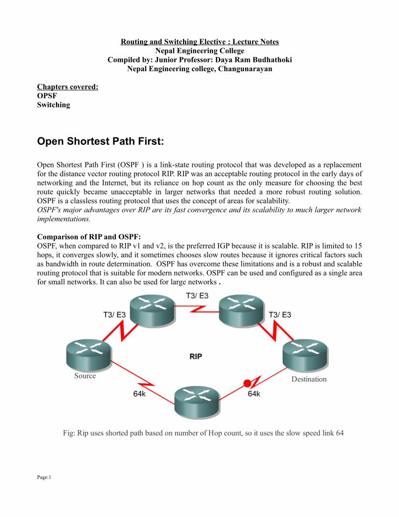
Comparison of RIP and OSPF:OSPF, when compared to RIP v1 and v2, is the preferred IGP because it is scalable. RIP is limited to 15 hops, it converges slowly, and it sometimes chooses slow routes because it ignores critical factors such as bandwidth in route determination. OSPF has overcome these limitations and is a robust and scalable routing protocol that is suitable for modern networks. OSPF can be used and configured as a single area for small networks. It can also be used for large networks .
Page:1
Fig: Rip uses shorted path based on number of Hop count, so it uses the slow speed link 64
Source Destination
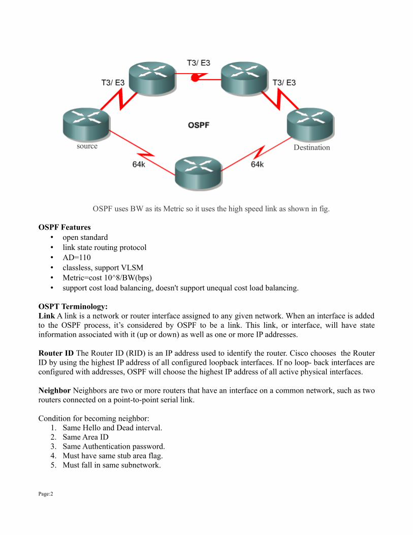
OSPF Features• open standard • link state routing protocol • AD=110 • classless, support VLSM• Metric=cost 10^8/BW(bps) • support cost load balancing, doesn't support unequal cost load balancing.
OSPT Terminology:Link A link is a network or router interface assigned to any given network. When an interface is added to the OSPF process, it’s considered by OSPF to be a link. This link, or interface, will have state information associated with it (up or down) as well as one or more IP addresses.
Router ID The Router ID (RID) is an IP address used to identify the router. Cisco chooses the Router ID by using the highest IP address of all configured loopback interfaces. If no loop- back interfaces are configured with addresses, OSPF will choose the highest IP address of all active physical interfaces.
Neighbor Neighbors are two or more routers that have an interface on a common network, such as two routers connected on a point-to-point serial link.
Condition for becoming neighbor: 1. Same Hello and Dead interval. 2. Same Area ID 3. Same Authentication password. 4. Must have same stub area flag. 5. Must fall in same subnetwork.
Page:2
OSPF uses BW as its Metric so it uses the high speed link as shown in fig.
source Destination

OSPF routers sends out hello packets every 10 seconds on a broadcast and every 30 secs on a non broadcast link
Adjacency An adjacency is a relationship between two OSPF routers that permits the direct exchange of route updates. OSPF is really picky about sharing routing information—unlike EIGRP, which directly shares routes with all of its neighbors. Instead, OSPF directly shares routes only with neighbors that have also established adjacencies. And not all neighbors will become adjacent—this depends upon both the type of network and the configuration of the routers.
Hello protocol The OSPF Hello protocol provides dynamic neighbor discovery and maintains neighbor relationships. Hello packets and Link State Advertisements (LSAs) build and maintain the topological database. Hello packets are addressed to 224.0.0.5.
Area:An ospf area is a logical grouping of routers that are running OSPF with identical topological databases. An area is a subdivision of the ospf routing domain. Each area runs SPF separately and summaries are passed between each Area.An OSPF area is a grouping of contiguous networks and routers. All routers in the same area share a common Area ID. Because a router can be a member of more than one area at a time, the Area ID is associated with specific interfaces on the router. This would allow some interfaces to belong to area 1 while the remaining interfaces can belong to area 0. All of the routers within the same area have the same topology table. When configuring OSPF, you’ve got to remember that there must be an area 0 and that this is typically configured on the routers that connect to the backbone of the network. Areas also play a role in establishing a hierarchical network organization—something that really enhances the scalability of OSPF!
OSPF routers are categorized based on the function they perform in the routing domain.The four different types of OSPF routers are:
• Internal routers: Routers that have all their interfaces in the same area and have identical
Page:3
LSDBs.
• Backbone routers: Routers that sit on the perimeter of the backbone area and have at least one interface connected to area 0. Backbone routers maintain OSPF routing information using the same procedures and algorithms as internal routers.
• Area border routers(ABR): Routers that have interfaces attached to multiple areas, maintain separate LSDBs for each area to which they connect, and route traffic destined to or arriving from other areas. Area border routers (ABRs) are exit points for the area, which means that routing information destined for another area can get there only via the ABR of the local area. ABRs can be configured to summarize the routing information from the LSDBs of their attached areas. ABRs distribute the routing information into the backbone. The backbone routers then forward the information to the other ABRs. In a multiarea network, an area can have one or more ABRs.
• Autonomous System Boundary Routers(ASBR): Routers that have at least one interface attached to an external internetwork (another autonomous system), such as a non-OSPF network. Autonomous system boundary routers (ASBRs) can import non-OSPF network information to the OSPF network and vice versa; this process is called route redistribution.
A router can exist as more than one router type. For example, if a router interconnects to area 0 and area 1, in addition to a non-OSPF network, it is both an ABR and an ASBR.A router has a separate LSDB for each area to which it connects; therefore, an ABR could have one LSDB for area 0 and another LSDB for another area in which it participates. Two routers belonging to the same area maintain identical LSDBs for that area.
An LSDB is synchronized between pairs of adjacent routers. On broadcast networks like Ethernet, an LSDB is synchronized between the router that is not a DR or a BDR (that is, a DROTHER) and its DR and BDR.
OSPF maintains three tables:Neighbor Table:
• Also known as the adjacency database.• Contains list of recognized neighbors.
Topology Database:• Typically referred as Link state databased (LSDB).• Contains all routers and their attached link in the area or network.• All routers within an area have an identical LSDB.
Routing Table:• Commonly named a forwarding database.• Contains lists of best path to the destination.
Page:4
condition for OSFP Network: • Area 0 is must. • Its position must be in such a way that it connects all existing area. • Area 0 is called backbone area. • No two area other than Area0 should be directly connected.
Link State Advertisement(LSA)A Link State Advertisement (LSA) is an OSPF data packet containing link-state and routing information that’s shared among OSPF routers. There are different types of LSA packets, and I’ll go into these shortly. An OSPF router will exchange LSA packets only with routers to which it has established adjacencies. LSA are the building blocks of LSDB. Individually, they act as database records. In combination, they describe the entire topology of an OSPF network or area. Link-state updates (LSUs) are the packets used for OSPF routing updates.
Router-ID:The Router ID (RID) is an IP address used to identify the router. Cisco choses the router-id based on the following order.
• router-id assigned with router-id ospf configuration command. • If router-id is not configured, then it looks for the highest IP address of all configured loopback
interfaces. • If lookback ip address is also not configured, then highest IP address of all configured physical
interfaces is chosen as the router-id.
OSPF Configuration:OSPF configuration:
Router(config)# router ospf <pid>Router(config-router) # network <Network-address> <Wildcard -mask> area <area-id>
process id: Local signifcant can rage form 1 to 65535 (2^16)area-id: 0 to 2^32.
wildcard mask: 255.255.255.255 – subnet-mask
Page:5
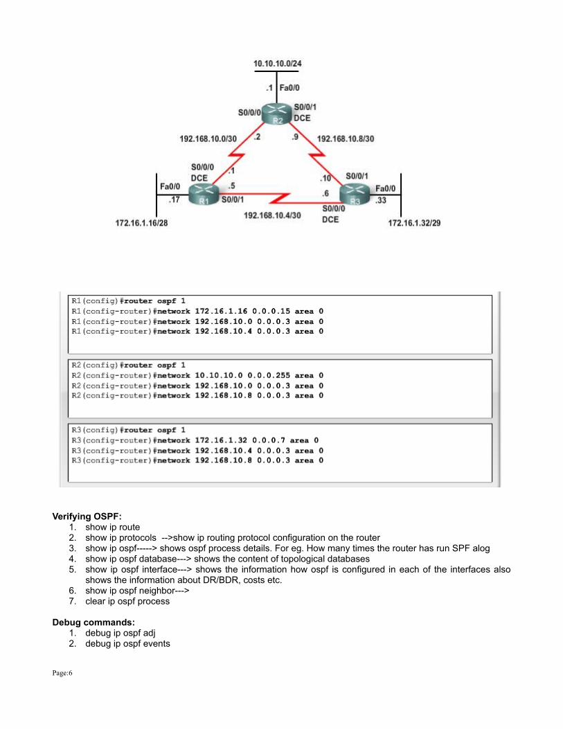
Verifying OSPF:1. show ip route2. show ip protocols -->show ip routing protocol configuration on the router3. show ip ospf-----> shows ospf process details. For eg. How many times the router has run SPF alog4. show ip ospf database---> shows the content of topological databases5. show ip ospf interface---> shows the information how ospf is configured in each of the interfaces also
shows the information about DR/BDR, costs etc.6. show ip ospf neighbor--->7. clear ip ospf process
Debug commands:1. debug ip ospf adj2. debug ip ospf events
Page:6
cost in OSPF:Cost=108/BW(bps). The cost is applied to the outgoing interface. The routing process will select the cumulative cost to a remote network. Changing the default cost:cost command manually overrides the default. Router(config)# int s0/0Router(config-if)# ip ospf cost <cost> (cost is a 16 bit value 0 – 65,535).you can mange the cost by setting the bandwidth command or setting the reference BW.Bandwidth command set the BW in kbps (it is used only in cost calculations not the actual BW)Router(config-router)# auto-cost reference-bandwidth 1000
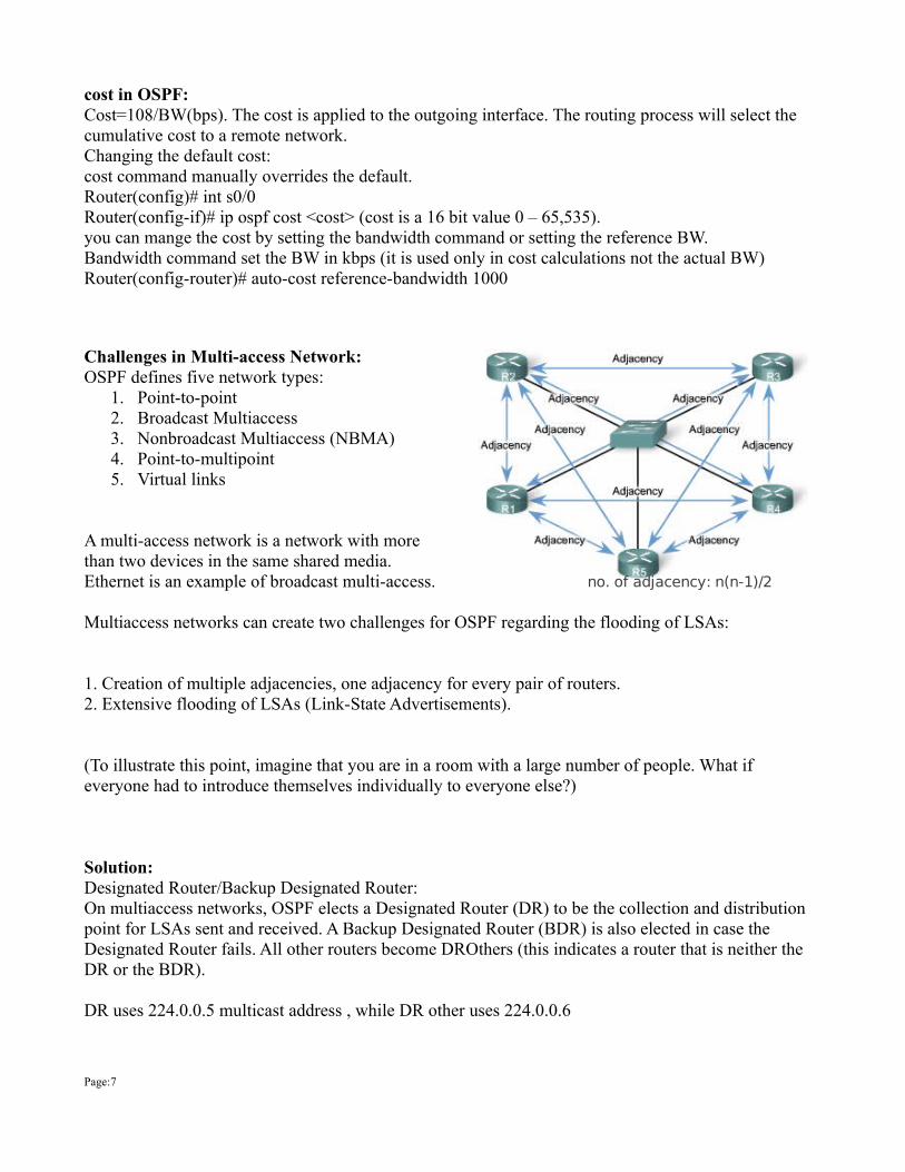
Challenges in Multi-access Network:OSPF defines five network types:
1. Point-to-point 2. Broadcast Multiaccess 3. Nonbroadcast Multiaccess (NBMA) 4. Point-to-multipoint 5. Virtual links
A multi-access network is a network with more than two devices in the same shared media. Ethernet is an example of broadcast multi-access.
Multiaccess networks can create two challenges for OSPF regarding the flooding of LSAs:
1. Creation of multiple adjacencies, one adjacency for every pair of routers. 2. Extensive flooding of LSAs (Link-State Advertisements).
(To illustrate this point, imagine that you are in a room with a large number of people. What if everyone had to introduce themselves individually to everyone else?)
Solution:Designated Router/Backup Designated Router:On multiaccess networks, OSPF elects a Designated Router (DR) to be the collection and distribution point for LSAs sent and received. A Backup Designated Router (BDR) is also elected in case the Designated Router fails. All other routers become DROthers (this indicates a router that is neither the DR or the BDR).
DR uses 224.0.0.5 multicast address , while DR other uses 224.0.0.6
Page:7
no. of adjacency: n(n-1)/2

The idea behind DR/BDR is that , router have a central point of contact for information exchange. Instead of each router exchanging updates with every routers on the segment, every router exchanges information with DR and BDR. The DR and BDR then relay the information to everyone else.
The routers which are neither DR nor BDR are called DR/Other. DROther will only maintain adjacencies with DR and BDR ( Full State) while it maintain 2-way with other DROther.
DR/BDR Election:• The router with the highest OSPF priority is selected as DR. The router with the second highest
priority value is the BDR.• Uses the router ID as the tie-breaker• The DR election is non-preemptive. I.e If a router with highest priority is added to the network then
it doesn't change the DR/BDR. The only time that a DR or BDR changes is when one of them is out of service.
Note: DR and BDRs are elected on a per network basis. An ospf area can contain more than one IP network, so each area can (& usually does) have multiple DR and BDR.A router can be configured to win an election on one interface and lose an election on other.
Changing OSPF Priority:use “ip ospf priority <vlaue>” interface configuration command to change the priority of the interface.Priority value can be any between 0 to 255. priority 0 indicates that router will not take part in the election and 255 indicates at least a tie.
Router(config)# int fa0/0Router(cofig-if)# ip ospf priority 100
Routing Table Entries:O -----> Intra AreaOIA----> Inter AreaOE1---> OSPF external routesOE2----> OSPF external routesON1----> NSSA external routes show up as N1 and N2 instead of E1 and ON2
OSPF supports two classification of external routes.E1-cost of routes increments as it passes thru the AS.E2-(Default) cost of route remains same as it passes thru AS.Uses:E2 :is used when there is a single exit point.E1: is used if there is are multiple path(Have to find the best path)
Page:8
Switched LAN Structure:
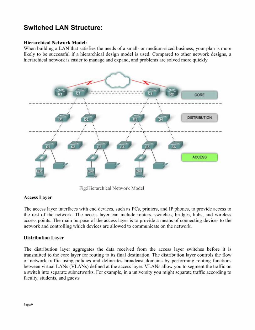
Hierarchical Network Model:When building a LAN that satisfies the needs of a small- or medium-sized business, your plan is more likely to be successful if a hierarchical design model is used. Compared to other network designs, a hierarchical network is easier to manage and expand, and problems are solved more quickly.
Access Layer
The access layer interfaces with end devices, such as PCs, printers, and IP phones, to provide access to the rest of the network. The access layer can include routers, switches, bridges, hubs, and wireless access points. The main purpose of the access layer is to provide a means of connecting devices to the network and controlling which devices are allowed to communicate on the network.
Distribution Layer
The distribution layer aggregates the data received from the access layer switches before it is transmitted to the core layer for routing to its final destination. The distribution layer controls the flow of network traffic using policies and delineates broadcast domains by performing routing functions between virtual LANs (VLANs) defined at the access layer. VLANs allow you to segment the traffic on a switch into separate subnetworks. For example, in a university you might separate traffic according to faculty, students, and guests
Page:9
Fig:Hierarchical Network Model

Core Layer
The core layer of the hierarchical design is the high-speed backbone of the internetwork. The core layer is critical for interconnectivity between distribution layer devices, so it is important for the core to be highly available and redundant. The core area can also connect to Internet resources. The core aggregates the traffic from all the distribution layer devices, so it must be capable of forwarding large amounts of data quickly.
Benefits of Hierarchical Network:
Half Duplex: Half-duplex communication relies on unidirectional data flow where sending and receiving data are not performed at the same time. This is similar to how walkie-talkies or two-way radios function in that only one person can talk at any one time. If someone talks while someone else is already speaking, a collision occurs. As a result, half-duplex communication implements CSMA/CD to help reduce the potential for collisions and detect them when they do happen. Half-duplex communications have performance issues due to the constant waiting, because data can only flow in one direction at a time. Half-duplex connections are typically seen in older hardware, such as hubs. Nodes that are attached to hubs that share their connection to a switch port must operate in half-duplex mode because the end computers must be able to detect collisions. Nodes can operate in a half-duplex mode if the NIC card cannot be configured for full duplex operations. In this case the port on the switch defaults to a half-duplex mode as well. Because of these limitations, full-duplex communication has replaced half duplex in more current hardware.
Page:10
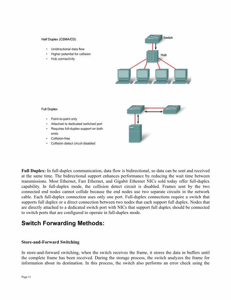
Full Duplex: In full-duplex communication, data flow is bidirectional, so data can be sent and received at the same time. The bidirectional support enhances performance by reducing the wait time between transmissions. Most Ethernet, Fast Ethernet, and Gigabit Ethernet NICs sold today offer full-duplex capability. In full-duplex mode, the collision detect circuit is disabled. Frames sent by the two connected end nodes cannot collide because the end nodes use two separate circuits in the network cable. Each full-duplex connection uses only one port. Full-duplex connections require a switch that supports full duplex or a direct connection between two nodes that each support full duplex. Nodes that are directly attached to a dedicated switch port with NICs that support full duplex should be connected to switch ports that are configured to operate in full-duplex mode.
Switch Forwarding Methods:
Store-and-Forward Switching
In store-and-forward switching, when the switch receives the frame, it stores the data in buffers until the complete frame has been received. During the storage process, the switch analyzes the frame for information about its destination. In this process, the switch also performs an error check using the
Page:11
Cyclic Redundancy Check (CRC) trailer portion of the Ethernet frame.
CRC uses a mathematical formula, based on the number of bits (1s) in the frame, to determine whether the received frame has an error. After confirming the integrity of the frame, the frame is forwarded out the appropriate port toward its destination. When an error is detected in a frame, the switch discards the frame. Discarding frames with errors reduces the amount of bandwidth consumed by corrupt data. Store-and-forward switching is required for Quality of Service (QoS) analysis on converged networks where frame classification for traffic prioritization is necessary. For example, voice over IP data streams need to have priority over web-browsing traffic.
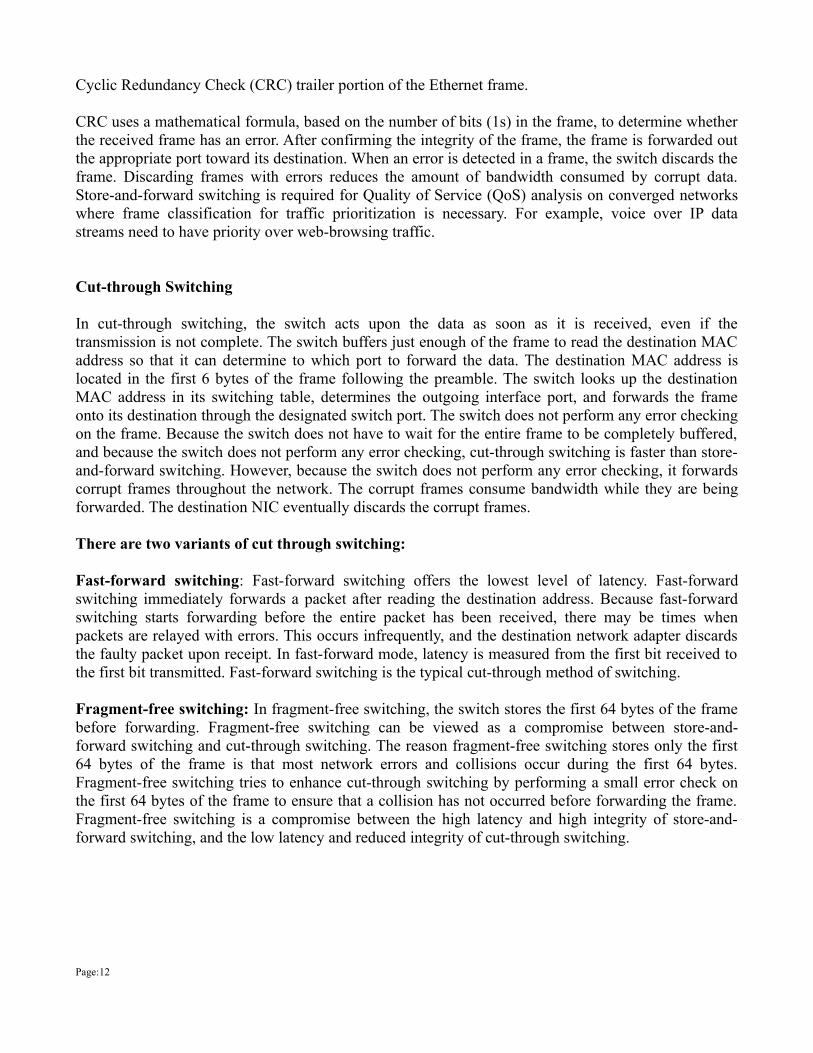
Cut-through Switching
In cut-through switching, the switch acts upon the data as soon as it is received, even if the transmission is not complete. The switch buffers just enough of the frame to read the destination MAC address so that it can determine to which port to forward the data. The destination MAC address is located in the first 6 bytes of the frame following the preamble. The switch looks up the destination MAC address in its switching table, determines the outgoing interface port, and forwards the frame onto its destination through the designated switch port. The switch does not perform any error checking on the frame. Because the switch does not have to wait for the entire frame to be completely buffered, and because the switch does not perform any error checking, cut-through switching is faster than store-and-forward switching. However, because the switch does not perform any error checking, it forwards corrupt frames throughout the network. The corrupt frames consume bandwidth while they are being forwarded. The destination NIC eventually discards the corrupt frames.
There are two variants of cut through switching:
Fast-forward switching: Fast-forward switching offers the lowest level of latency. Fast-forward switching immediately forwards a packet after reading the destination address. Because fast-forward switching starts forwarding before the entire packet has been received, there may be times when packets are relayed with errors. This occurs infrequently, and the destination network adapter discards the faulty packet upon receipt. In fast-forward mode, latency is measured from the first bit received to the first bit transmitted. Fast-forward switching is the typical cut-through method of switching.
Fragment-free switching: In fragment-free switching, the switch stores the first 64 bytes of the frame before forwarding. Fragment-free switching can be viewed as a compromise between store-and-forward switching and cut-through switching. The reason fragment-free switching stores only the first 64 bytes of the frame is that most network errors and collisions occur during the first 64 bytes. Fragment-free switching tries to enhance cut-through switching by performing a small error check on the first 64 bytes of the frame to ensure that a collision has not occurred before forwarding the frame. Fragment-free switching is a compromise between the high latency and high integrity of store-and-forward switching, and the low latency and reduced integrity of cut-through switching.
Page:12
Communications in a switched LAN network occur in three ways: unicast, broadcast, and multicast: Unicast: Communication in which a frame is sent from one host and addressed to one specific destination. In unicast transmission, there is just one sender and one receiver. Unicast transmission is the predominant form of transmission on LANs and within the Internet. Examples of unicast transmissions include HTTP, SMTP, FTP, and Telnet.
Broadcast: Communication in which a frame is sent from one address to all other addresses. In this case, there is just one sender, but the information is sent to all connected receivers. Broadcast transmission is essential when sending the same message to all devices on the LAN. An example of a broadcast transmission is the address resolution query that the address resolution protocol (ARP) sends to all computers on a LAN.
Multicast: Communication in which a frame is sent to a specific group of devices or clients. Multicast transmission clients must be members of a logical multicast group to receive the information. An example of multicast transmission is the video and voice transmissions associated with a network-based, collaborative business meeting.
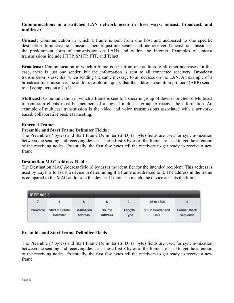
Ethernet Frame:Preamble and Start Frame Delimiter Fields :The Preamble (7 bytes) and Start Frame Delimiter (SFD) (1 byte) fields are used for synchronization between the sending and receiving devices. These first 8 bytes of the frame are used to get the attention of the receiving nodes. Essentially, the first few bytes tell the receivers to get ready to receive a new frame.
Destination MAC Address Field : The Destination MAC Address field (6 bytes) is the identifier for the intended recipient. This address is used by Layer 2 to assist a device in determining if a frame is addressed to it. The address in the frame is compared to the MAC address in the device. If there is a match, the device accepts the frame.
Preamble and Start Frame Delimiter Fields
The Preamble (7 bytes) and Start Frame Delimiter (SFD) (1 byte) fields are used for synchronization between the sending and receiving devices. These first 8 bytes of the frame are used to get the attention of the receiving nodes. Essentially, the first few bytes tell the receivers to get ready to receive a new frame.
Page:13
Destination MAC Address Field The Destination MAC Address field (6 bytes) is the identifier for the intended recipient. This address is used by Layer 2 to assist a device in determining if a frame is addressed to it. The address in the frame is compared to the MAC address in the device. If there is a match, the device accepts the frame.
Length/Type Field The Length/Type field (2 bytes) defines the exact length of the frame's data field. This field is used later as part of the Frame Check Sequence (FCS) to ensure that the message was received properly. Only a frame length or a frame type can be entered here. If the purpose of the field is to designate a type, the Type field describes which protocol is implemented. When a node receives a frame and the Length/Type field designates a type, the node determines which higher layer protocol is present. If the two-octet value is equal to or greater than 0x0600 hexadecimal or 1536 decimal, the contents of the Data Field are decoded according to the protocol indicated; if the two-byte value is less than 0x0600 then the value represents the length of the data in the frame.
Data and Pad Fields The Data and Pad fields (46 to 1500 bytes) contain the encapsulated data from a higher layer, which is a generic Layer 3 PDU, or more commonly, an IPv4 packet. All frames must be at least 64 bytes long (minimum length aides the detection of collisions). If a small packet is encapsulated, the Pad field is used to increase the size of the frame to the minimum size.
Frame Check Sequence Field The FCS field (4 bytes) detects errors in a frame. It uses a cyclic redundancy check (CRC). The sending device includes the results of a CRC in the FCS field of the frame. The receiving device receives the frame and generates a CRC to look for errors. If the calculations match, no error has occurred. If the calculations do not match, the frame is dropped.
MAC Addressing and Switch MAC Table:Switches use MAC addresses to direct network communications through their switch fabric to the appropriate port toward the destination node. The switch fabric is the integrated circuits and the accompanying machine programming that allows the data paths through the switch to be controlled. For a switch to know which port to use to transmit a unicast frame, it must first learn which nodes exist on each of its ports.
A switch determines how to handle incoming data frames by using its MAC address table. A switch builds its MAC address table by recording the MAC addresses of the nodes connected to each of its ports. Once a MAC address for a specific node on a specific port is recorded in the address table, the switch then knows to send traffic destined for that specific node out the port mapped to that node for subsequent transmissions.When an incoming data frame is received by a switch and the destination MAC address is not in the table, the switch forwards the frame out all ports, except for the port on which it was received. When the destination node responds, the switch records the node's MAC address in the address table from the frame's source address field. In networks with multiple interconnected switches, the MAC address tables record multiple MAC addresses for the ports connecting the switches which reflect the node's beyond. Typically, switch ports used to interconnect two switches have multiple MAC addresses recorded in the MAC address table.
Page:14
Page:15
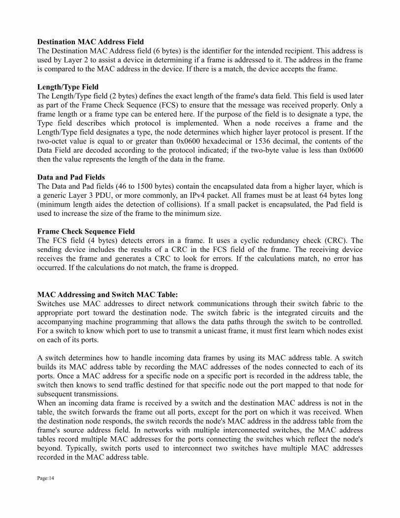
Step1: The switch receives a frame destined for pc2 on port1 from PC1.
Step2:The switch enters the source MAC address and the switch port that received the frame into the MAC table
Step3: Because the destination address is a broadcast address, the switch floods the frame to all ports except the port on which it receives the frame
Step4: The destination device replies to the broadcast address with a unicast frame addressed to PC1.
Step5: The switch enters the source MAC address of PC2 and port number of the switch port that received the frame into the MAC table. The destination address of the frame and its associated port is found in the MAC table.
Step6: The switch can now forward frames between source and destination devices without flooding. Because it has entries in the MAC table that identify the associated port.

Collision Domain and Broadcast Domain:
Collision Domain: In Ethernet, the network area within which the frame that are collided are propagated. Repeaters and Hubs propagate collisions; LAN switches, bridge and routers do not. Each port of a switch acts as a collision domain.
Broadcast Domain: The set of all devices that will receive broadcast frames originating from any device within the set. Broadcast domain are typically bounded by the routers because routers do not forward broadcast frame.
Virtual LAN(VLAN)
Before understanding VLANs, you must first have a specific understanding of the definition of a LAN. Although you can think about LANs from many perspectives, one perspective in particular can help you understand VLANs: A LAN includes all devices in the same broadcast domain. A broadcast domain includes the set of all LAN-connected devices that when any of the devices sends a broadcast frame, all the other devices get a copy of the frame. So, you can think of a LAN and a broadcast domain as being basically the same thing. Without VLANs, a switch considers all its interfaces to be in the same broadcast domain; in others words, all connected devices are in the same LAN. With VLANs, a switch can put some interfaces into one broadcast domain and some into another, creating multiple broadcast domains. These individual broadcast domains created by the switch are called virtual LANs. Figure below shows an example, with two VLANs and two devices in each VLAN.
Page:16
Fig: Sample Network with Two VLANs Using One Switch
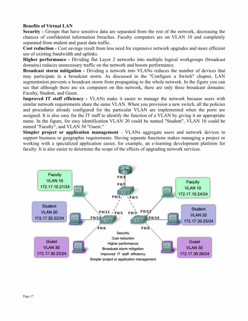
Benefits of Virtual LAN Security - Groups that have sensitive data are separated from the rest of the network, decreasing the chances of confidential information breaches. Faculty computers are on VLAN 10 and completely separated from student and guest data traffic. Cost reduction - Cost savings result from less need for expensive network upgrades and more efficient use of existing bandwidth and uplinks. Higher performance - Dividing flat Layer 2 networks into multiple logical workgroups (broadcast domains) reduces unnecessary traffic on the network and boosts performance. Broadcast storm mitigation - Dividing a network into VLANs reduces the number of devices that may participate in a broadcast storm. As discussed in the "Configure a Switch" chapter, LAN segmentation prevents a broadcast storm from propagating to the whole network. In the figure you can see that although there are six computers on this network, there are only three broadcast domains: Faculty, Student, and Guest. Improved IT staff efficiency - VLANs make it easier to manage the network because users with similar network requirements share the same VLAN. When you provision a new switch, all the policies and procedures already configured for the particular VLAN are implemented when the ports are assigned. It is also easy for the IT staff to identify the function of a VLAN by giving it an appropriate name. In the figure, for easy identification VLAN 20 could be named "Student", VLAN 10 could be named "Faculty", and VLAN 30 "Guest." Simpler project or application management - VLANs aggregate users and network devices to support business or geographic requirements. Having separate functions makes managing a project or working with a specialized application easier, for example, an e-learning development platform for faculty. It is also easier to determine the scope of the effects of upgrading network services.
Page:17
Types of VLAN
Data VLAN :
A data VLAN is a VLAN that is configured to carry only user-generated traffic. A VLAN could carry voice-based traffic or traffic used to manage the switch, but this traffic would not be part of a data VLAN. It is common practice to separate voice and management traffic from data traffic. The importance of separating user data from switch management control data and voice traffic is highlighted by the use of a special term used to identify VLANs that only carry user data - a "data VLAN". A data VLAN is sometimes referred to as a user VLAN.
Default VLAN All switch ports become a member of the default VLAN after the initial boot up of the switch. Having all the switch ports participate in the default VLAN makes them all part of the same broadcast domain. This allows any device connected to any switch port to communicate with other devices on other switch ports. The default VLAN for Cisco switches is VLAN 1. VLAN 1 has all the features of any VLAN, except that you cannot rename it and you can not delete it. Layer 2 control traffic, such as CDP and spanning tree protocol traffic, will always be associated with VLAN 1 - this cannot be changed. In the figure, VLAN 1 traffic is forwarded over the VLAN trunks connecting the S1, S2, and S3 switches. It is a security best practice to change the default VLAN to a VLAN other than VLAN 1; this entails configuring all the ports on the switch to be associated with a default VLAN other than VLAN 1. VLAN trunks support the transmission of traffic from more than one VLAN.
Native VLAN A native VLAN is assigned to an 802.1Q trunk port. An 802.1Q trunk port supports traffic coming from many VLANs (tagged traffic) as well as traffic that does not come from a VLAN (untagged traffic). The 802.1Q trunk port places untagged traffic on the native VLAN. In the figure, the native VLAN is VLAN 99. Untagged traffic is generated by a computer attached to a switch port that is configured with the native VLAN. Native VLANs are set out in the IEEE 802.1Q specification to maintain backward compatibility with untagged traffic common to legacy LAN scenarios. For our purposes, a native VLAN serves as a common identifier on opposing ends of a trunk link. It is a best practice to use a VLAN other than VLAN 1 as the native VLAN.
Management VLAN A management VLAN is any VLAN you configure to access the management capabilities of a switch. VLAN 1 would serve as the management VLAN if you did not proactively define a unique VLAN to serve as the management VLAN. You assign the management VLAN an IP address and subnet mask. A switch can be managed via HTTP, Telnet, SSH, or SNMP. Since the out-of-the-box configuration of a Cisco switch has VLAN 1 as the default VLAN, you see that VLAN 1 would be a bad choice as the management VLAN; you wouldn't want an arbitrary user connecting to a switch to default to the management VLAN.
There are two different types of links in a switched environment: 1. Access ports2. Trunk ports
A switch port can belong to only one VLAN if it is an access port or all VLANs if it is a trunk port. You
Page:18
can manually configure a port as an access or trunk port .
Access ports An access port belongs to and carries the traffic of only one VLAN. Traffic is both received and sent in native formats with no VLAN tagging whatsoever. Anything arriving on an access port is simply assumed to belong to the VLAN assigned to the port. voice access ports:Nowadays, most switches will allow you to add a second VLAN to an access port on a switch port for your voice traffic; it’s called the voice VLAN .
Trunk Ports The term trunk port was inspired by the telephone system trunks that carry multiple telephone conversations at a time. So it follows that trunk ports can similarly carry multiple VLANs at a time. A trunk link is a 100- or 1000Mbps point-to-point link between two switches, between a switch and router, or even between a switch and server, and it carries the traffic of multiple VLANs at a time .
VLAN Configuration:Two step Process for static VLAN:step1: Creating and Naming VLANsSwitch(config)#vlan ? <1-1005> ISL VLAN IDs 1-1005Switch(config)#vlan 10Switch(config-vlan)#name accountSwitch(config-vlan)#
Switch#sh vlan brief VLAN Name Status Ports---- -------------------------------- --------- -------------------------------1 default active Fa0/1, Fa0/2, Fa0/3, Fa0/4 Fa0/5, Fa0/6, Fa0/7, Fa0/8 Fa0/9, Fa0/10, Fa0/11, Fa0/12 Fa0/13, Fa0/14, Fa0/15, Fa0/16 Fa0/17, Fa0/18, Fa0/19, Fa0/20 Fa0/21, Fa0/22, Fa0/23, Fa0/24 Gig1/1, Gig1/210 account active 1002 fddi-default active 1003 token-ring-default active 1004 fddinet-default active 1005 trnet-default active Switch#
step2: Assigning Switch Ports to VLANs :Switch(config)#interface fa0/5Switch(config-if)#switchport mode access Switch(config-if)#switchport access vlan 10Switch(config-if)#
Page:19
By starting with the switchport mode access command, you’re telling the switch that this is a layer 2 port. You can then assign a VLAN to the port with the switchport access command. Remember, you can choose many ports to configure at the same time if you use the interface range command. Switch(config)#interface range fa0/10 -20Switch(config-if-range)#
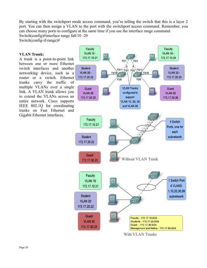
VLAN Trunk:A trunk is a point-to-point link between one or more Ethernet switch interfaces and another networking device, such as a router or a switch. Ethernet trunks carry the traffic of multiple VLANs over a single link. A VLAN trunk allows you to extend the VLANs across an entire network. Cisco supports IEEE 802.1Q for coordinating trunks on Fast Ethernet and Gigabit Ethernet interfaces.
Page:20
Without VLAN Trunk
With VLAN Trunks
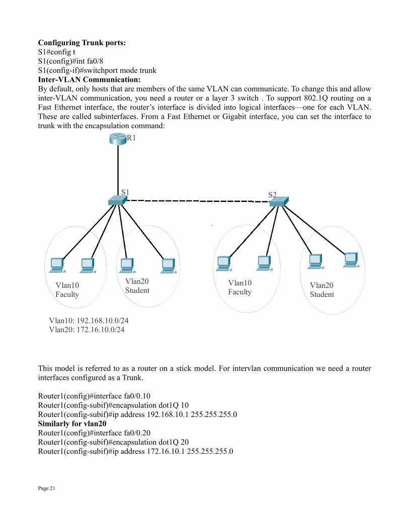
Configuring Trunk ports: S1#config t S1(config)#int fa0/8 S1(config-if)#switchport mode trunk Inter-VLAN Communication:By default, only hosts that are members of the same VLAN can communicate. To change this and allow inter-VLAN communication, you need a router or a layer 3 switch . To support 802.1Q routing on a Fast Ethernet interface, the router’s interface is divided into logical interfaces—one for each VLAN. These are called subinterfaces. From a Fast Ethernet or Gigabit interface, you can set the interface to trunk with the encapsulation command:
This model is referred to as a router on a stick model. For intervlan communication we need a router interfaces configured as a Trunk.
Router1(config)#interface fa0/0.10Router1(config-subif)#encapsulation dot1Q 10Router1(config-subif)#ip address 192.168.10.1 255.255.255.0Similarly for vlan20Router1(config)#interface fa0/0.20Router1(config-subif)#encapsulation dot1Q 20Router1(config-subif)#ip address 172.16.10.1 255.255.255.0
Page:21
Vlan10Faculty
Vlan10Faculty
Vlan20Student
Vlan20Student
R1
S1 S2
Vlan10: 192.168.10.0/24Vlan20: 172.16.10.0/24
Spanning Tree Protocol:
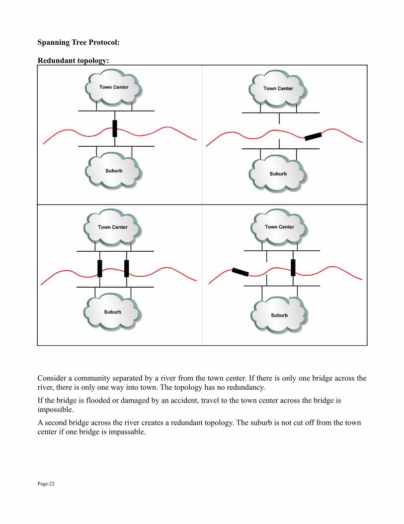
Redundant topology:
Consider a community separated by a river from the town center. If there is only one bridge across the river, there is only one way into town. The topology has no redundancy.
If the bridge is flooded or damaged by an accident, travel to the town center across the bridge is impossible.
A second bridge across the river creates a redundant topology. The suburb is not cut off from the town center if one bridge is impassable.
Page:22
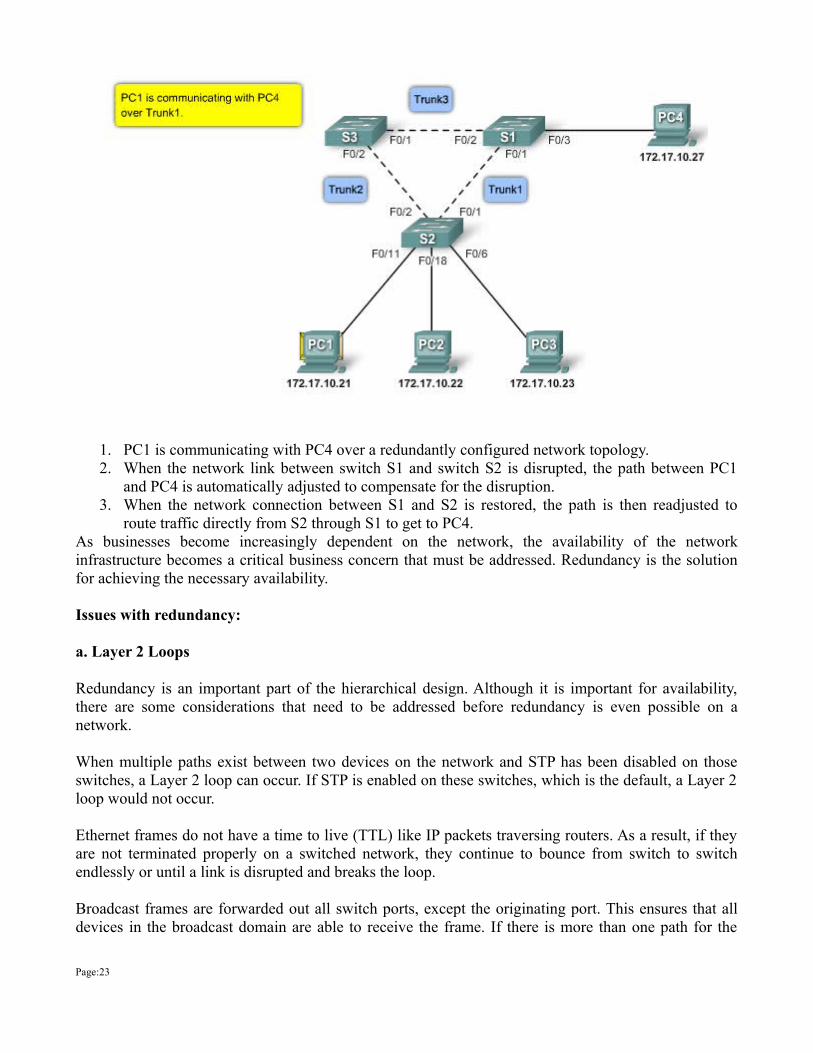
1. PC1 is communicating with PC4 over a redundantly configured network topology. 2. When the network link between switch S1 and switch S2 is disrupted, the path between PC1
and PC4 is automatically adjusted to compensate for the disruption. 3. When the network connection between S1 and S2 is restored, the path is then readjusted to
route traffic directly from S2 through S1 to get to PC4. As businesses become increasingly dependent on the network, the availability of the network infrastructure becomes a critical business concern that must be addressed. Redundancy is the solution for achieving the necessary availability. Issues with redundancy:
a. Layer 2 Loops
Redundancy is an important part of the hierarchical design. Although it is important for availability, there are some considerations that need to be addressed before redundancy is even possible on a network.
When multiple paths exist between two devices on the network and STP has been disabled on those switches, a Layer 2 loop can occur. If STP is enabled on these switches, which is the default, a Layer 2 loop would not occur.
Ethernet frames do not have a time to live (TTL) like IP packets traversing routers. As a result, if they are not terminated properly on a switched network, they continue to bounce from switch to switch endlessly or until a link is disrupted and breaks the loop.
Broadcast frames are forwarded out all switch ports, except the originating port. This ensures that all devices in the broadcast domain are able to receive the frame. If there is more than one path for the
Page:23
frame to be forwarded out, it can result in an endless loop.b. Broadcast Storms A broadcast storm occurs when there are so many broadcast frames caught in a Layer 2 loop that all available bandwidth is consumed. Consequently, no bandwidth is available bandwidth for legitimate traffic, and the network becomes unavailable for data communication.
A broadcast storm is inevitable on a looped network. As more devices send broadcasts out on the network, more and more traffic gets caught in the loop, eventually creating a broadcast storm that causes the network to fail.
There are other consequences for broadcast storms. Because broadcast traffic is forwarded out every port on a switch, all connected devices have to process all broadcast traffic that is being flooded endlessly around the looped network. This can cause the end device to malfunction because of the high processing requirements for sustaining such a high traffic load on the network interface card.
c. Duplicate Unicast Frames Broadcast frames are not the only type of frames that are affected by loops. Unicast frames sent onto a looped network can result in duplicate frames arriving at the destination device.
STP Topology
Redundancy increases the availability of the network topology by protecting the network from a single point of failure, such as a failed network cable or switch. When redundancy is introduced into a Layer 2 design, loops and duplicate frames can occur. Loops and duplicate frames can have severe consequences on a network. The Spanning Tree Protocol (STP) was developed to address these issues.
STP ensures that there is only one logical path between all destinations on the network by intentionally blocking redundant paths that could cause a loop. A port is considered blocked when network traffic is prevented from entering or leaving that port. This does not include bridge protocol data unit (BPDU) frames that are used by STP to prevent loops. You will learn more about STP BPDU frames later in the chapter. Blocking the redundant paths is critical to preventing loops on the network. The physical paths still exist to provide redundancy, but these paths are disabled to prevent the loops from occurring. If the path is ever needed to compensate for a network cable or switch failure, STP recalculates the paths and unblocks the necessary ports to allow the redundant path to become active.
Spanning-tree TerminologyRoot bridge The root bridge is the bridge with the best bridge ID. With STP, the key is for all the switches in the network to elect a root bridge that becomes the focal point in the network. All other decisions in the network—such as which port is to be blocked and which port is to be put in forwarding mode—are made from the perspective of this root bridge.
BPDU All the switches exchange information to use in the selection of the root switch as well as in subsequent configuration of the network. Each switch compares the parameters in the Bridge Protocol Data Unit (BPDU) that it sends to one neighbor with the one that it receives from another neighbor.
Page:24
Bridge ID The bridge ID is how STP keeps track of all the switches in the network. It is determined by a combination of the bridge priority (32,768 by default on all Cisco switches) and the base MAC address. The bridge with the lowest bridge ID becomes the root bridge in the network. Nonroot bridges These are all bridges that are not the root bridge. Nonroot bridges exchange BPDUs with all bridges and update the STP topology database on all switches, preventing loops and providing a measure of defense against link failures.
Port cost Port cost determines the best path when multiple links are used between two switches and none of the links is a root port. The cost of a link is determined by the bandwidth of a link.
Root port The root port exists on non-root bridges and is the switch port with the best path to the root bridge. Root ports forward traffic toward the root bridge. Only one root port is allowed per bridge. If more than one link connects to the root bridge, then a port cost is determined by checking the bandwidth of each link. The lowest-cost port becomes the root port. If multiple links have the same cost, the bridge with the lower advertising bridge ID is used. Since multiple links can be from the same device, the lowest port number will be used.
Designated port: The designated port exists on root and non-root bridges. For root bridges, all switch ports are designated ports. For non-root bridges, a designated port is the switch port that receives and forwards frames toward the root bridge as needed. Only one designated port is allowed per segment. If multiple switches exist on the same segment, an election process determines the designated switch, and the corresponding switch port begins forwarding frames for the segment. A designated port will be marked as a forwarding port.
Nondesignated port: The non-designated port is a switch port that is blocked, so it is not forwarding data frames and not populating the MAC address table with source addresses. A non-designated port is not a root port or a designated port. For some variants of STP, the non-designated port is called an alternate port.
Forwarding port A forwarding port forwards frames.
Blocked port A blocked port is the port that, in order to prevent loops, will not forward frames. However, a blocked port will always listen to frames.
Disabled Port : The disabled port is a switch port that is administratively shut down. A disabled port does not function in the spanning-tree process.
Verifying spanning tree:Switch# show spanning-tree
Port States: STP determines the logical loop-free path throughout the broadcast domain. The spanning tree is determined through the information learned by the exchange of the BPDU frames between the interconnected switches. To facilitate the learning of the logical spanning tree, each switch port
Page:25
transitions through five possible port states and three BPDU timers.
The spanning tree is determined immediately after a switch is finished booting up. If a switch port were to transition directly from the blocking to the forwarding state, the port could temporarily create a data loop if the switch was not aware of all topology information at the time. For this reason, STP introduces five port states. The table summarizes what each port state does. The following provides some additional information on how the port states ensure that no loops are created during the creation of the logical spanning tree.
Blocking - The port is a non-designated port and does not participate in frame forwarding. The port receives BPDU frames to determine the location and root ID of the root bridge switch and what port roles each switch port should assume in the final active STP topology.
Listening - STP has determined that the port can participate in frame forwarding according to the BPDU frames that the switch has received thus far. At this point, the switch port is not only receiving BPDU frames, it is also transmitting its own BPDU frames and informing adjacent switches that the switch port is preparing to participate in the active topology.
Learning - The port prepares to participate in frame forwarding and begins to populate the MAC address table.
Forwarding - The port is considered part of the active topology and forwards frames and also sends and receives BPDU frames.
Disabled - The Layer 2 port does not participate in spanning tree and does not forward frames. The disabled state is set when the switch port is administratively disabled.
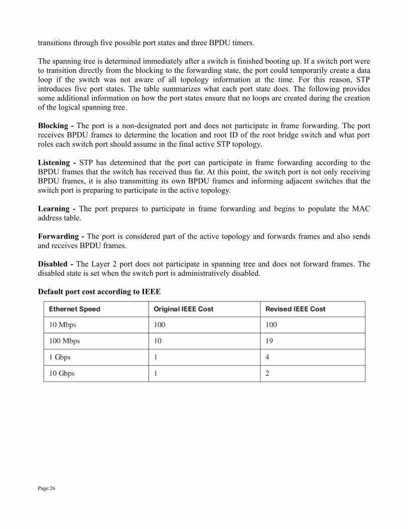
Default port cost according to IEEE
Page:26
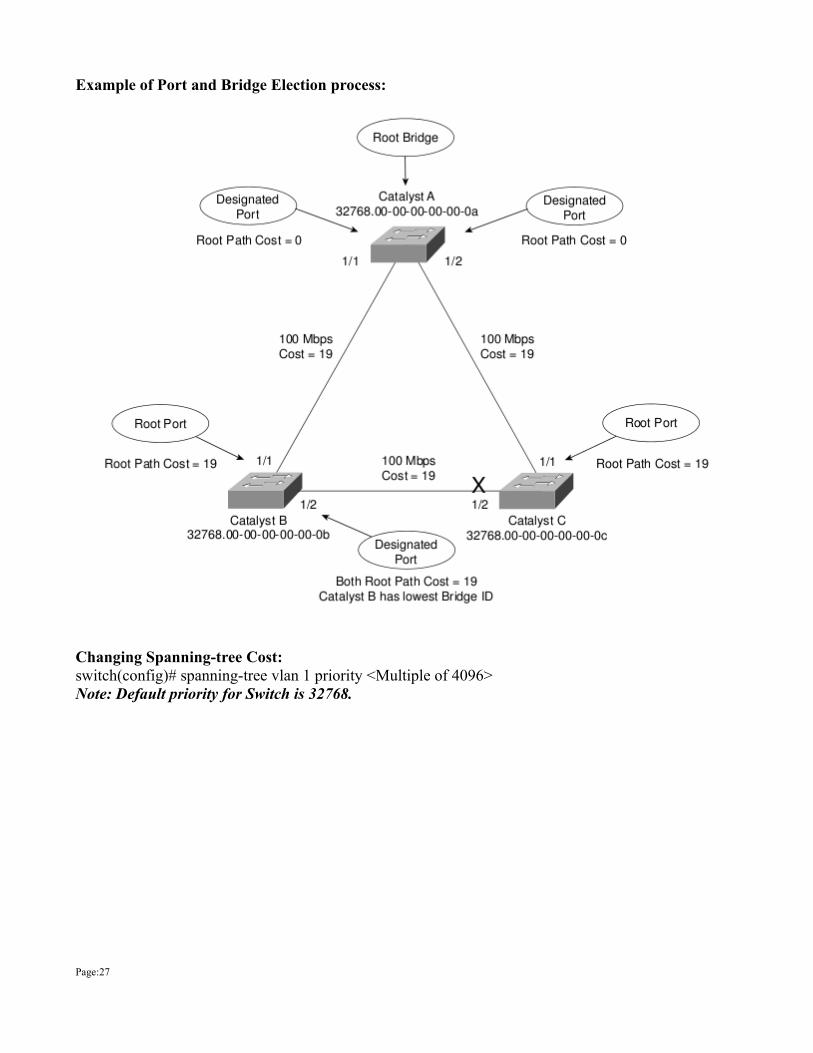
Example of Port and Bridge Election process:
Changing Spanning-tree Cost:switch(config)# spanning-tree vlan 1 priority <Multiple of 4096>Note: Default priority for Switch is 32768.
Page:27