openade 1.0 system requirements specificationosgug.ucaiug.org/sgsystems/openade/shared...
TRANSCRIPT

UCAIug OpenSG OpenADE Task ForceOpenADE 1.0 System Requirements Specification
OpenADE 1.0 System Requirements Specification
Version: Draft v0.1
Release Date: October 16, 2009
Draft v0.1, May 7, 2023 Page 1 of 27© Copyright 2009, OpenSG, All Rights Reserved
12
1
2
3
4
5
6
7
8
9
10
34

UCAIug OpenSG OpenADE Task ForceOpenADE 1.0 System Requirements Specification
AcknowledgementsThe following individuals and their companies are members of the UCAIug OpenSG and have contributed and/or provided support to the work of the OpenADE System Requirements Specification:
…
The OpenADE Task Force wishes to thank all of the above-mentioned individuals and their companies for their support of this important endeavor, as it sets a key foundation for interoperable Smart Grid of the future.
Draft v0.1, May 7, 2023 Page 2 of 27© Copyright 2009, OpenSG, All Rights Reserved
12
1
2345
6789
10
34

Document History
Revision HistoryDate of this revision: Oct. 16, 2009
Revision Number
Revision Date
RevisionBy
Summary of Changes Changes marked
0.1 10/16/09 Steve Van Ausdall Initial draft “shell”. N
Open Issues LogLast updated: Oct. 16, 2009
Issue Number
Issue Date ProvidedBy
Summary of the Issue
1
1
234
567
8
2

Contents1 Introduction................................................................................................................6
1.1 Purpose......................................................................................................................................... 6
1.2 Scope............................................................................................................................................ 7
1.3 Acronyms and Abbreviations.........................................................................................................8
1.4 External Considerations and References......................................................................................8
1.5 Document Overview...................................................................................................................... 8
2 Architecture Overview..............................................................................................112.1 Architecture Vision....................................................................................................................... 11
2.2 Architecture Guiding Principles...................................................................................................12
2.3 Architectural Considerations........................................................................................................12
3 OpenADE Systems Architecture..............................................................................143.1 OpenADE Business Architecture View........................................................................................14
3.2 Integration Requirements Specification.......................................................................................16
3.2.1 Functional Requirements – Business Processes.................................................................16
3.2.2 Functional Requirements – Integration Services..................................................................16
3.2.3 Technical Requirements – Integration Services...................................................................16
3.3 OpenADE Application Architecture View.....................................................................................19
3.4 OpenADE Data Architecture View...............................................................................................20
3.4.1 Meter Reading and Event View............................................................................................20
3.5 OpenADE Technical Architecture View.......................................................................................21
3.5.1 Security Standards...............................................................................................................21
3.5.2 Service Patterns................................................................................................................... 22
3.5.3 Governance.......................................................................................................................... 23
4 Appendices..............................................................................................................244.1 Terms and Definitions.................................................................................................................. 24
List of FiguresFigure 1. OpenADE component diagram showing the scope of the service definition effort.......................7
Figure 2. The Open Group Architecture Framework (TOGAF) architecture development cycle.................9
Figure 3. OpenADE Stakeholders Overview.............................................................................................11
Figure 4. Overview of Business Process Flows........................................................................................14
Figure 5. Overview diagram of Logical Components................................................................................15
Figure 6. Services that are provided or consumed by OpenADE Data Service component.....................19
Figure 7. Class relationship diagram representing the meter reading and related events........................21
1
1
23
4
5
6
7
89
10
11
1213
14
15
16
17
18
19
20
21
22
23
24
2526
2728
29
30
31
32
33
34
2

1
1
2

1 IntroductionOpenADE is an industry-led initiative under Open Smart Grid (OpenSG) within the UCA International Users Group (UCAIug). The OpenADE Task Force defines systems requirements, policies and principles, best practices, and services, required for information exchange and control between 3rd Party energy usage data analysis providers (EUDAPs), utility enterprise front and back office systems, and consumer customers. OpenADE, as an open user group forum, is developing a set of utility-ratified requirements and specifications for utilities to adopt and for vendors to implement. The end-state of this effort will contribute to the development of open and interoperable utility data sharing applications. To that end, OpenADE will work very closely with relevant Standards Development Organizations (SDOs) such as IEC, NAESB, NEMA, OASIS, and ZigBee, as well as Utilities, Vendors, Consumer, and Regulatory groups, to ensure that OpenADE work products are compatible with their directions and specifications and will be adopted as standards.
The OpenADE group is organized with three sub-groups:
Use Case Team: to develop business process models and functional requirements.
SRS Team: to develop overall systems architecture principles, integration requirements and specifications.
Service Definition Team: to develop standards-based, platform independent integration services that support the business processes, adhere to the architecture principles and patterns, and are open and interoperable when adopted by vendor products.
The main goal of the task force is to work with utilities and vendors to develop requirements and specifications necessary to enable vendors to gain access to consumer usage, and possibly in version 2.0, pricing and billing data. This will be achieved by defining and making the following OpenADE related items available to the market:
Common business processes
Common architecture principles and patterns
Common information model
Common integration services (functional & informational)
Tested interoperability between vendor products
Our current charter can be found on Smartgridipedia, at http://www.smartgridipedia.org/index.php/OpenADE_Charter.
1.1 PurposeThe purpose of this document is to provide both the functional and technical requirements needed to serve as the “rules of engagement” for how vendors and utilities could implement recommended requirements and design specifications in order to achieve interoperability. The functional requirements will be driven by business processes and the technical requirements will be driven by desired architectural principles and best practices.
1
1
23456789
101112
13
14
1516
171819
20212223
24
25
26
27
28
2930
313233343536
2

1.2 ScopeThe scope of OpenADE SRS includes authorization and transfer of consumer consumption, price, and billing related information from utilities to 3rd Party vendors. The SRS defines the logical components and business functions in order to identify the interfaces that must be specified to enable interoperability across different implementations, for many utilities to many vendors. It includes architectural aspects and specific requirements. The inputs include OpenADE use cases, as well as industry best practices and standards, including information models and other specifications.
The scope of OpenADE SRS document is to describe OpenADE is as an ecosystem of integrated applications, what collective functions it intends to provide, what system architecture is required to deliver the intended functions, and what individual applications and the underlining technology infrastructure it requires to support the establishment of OpenADE as such a system. This would lead to open and interoperable components that can be delivered with different vendor products and/or solutions within the scope of OpenADE.
Figure 1. OpenADE component diagram showing the scope of the service definition effort.
OpenADE SRS does not include the following items that are typically a part of solution architecture. Some of them are or have been addressed by other parts of the OpenSG initiative. Others will need to be dealt with specifically for each implementation.
1
1234567
89
10111213
14
15
16
171819
2

Network and hardware infrastructure architecture
Operational architecture (TBD)
Testing methodology and architecture (TBD)
Application internal architecture (utility / vendor specific)
1.3 Acronyms and AbbreviationsThis subsection provides a list of all acronyms and abbreviations required to properly interpret the OpenSG OpenADE System Requirements Specification.
SRS System Requirements SpecificationSDO Standards Development OrganizationCIM IEC TC57 Common Information Model TOGAF The Open Group Architecture Framework UML Unified Modeling LanguageDDL Data Definition LanguageXSD XML SchemaWSDL Web Services Definition LanguageESM Enterprise Semantic ModelWS-I Web Service – Interoperability (W3C)OASIS Organization for the Advancement of Structured
Information Standards
1.4 External Considerations and ReferencesThe work of OpenADE SRS is dependent upon the best practices available from the following entities and standards organizations:
IEC TC57 Working Group 14 (IEC 61968) series of standards, including the Common Information Model
GridWise Architecture Council Service-Oriented Architecture Standards from W3C, WS-I and OASIS The Open Group, TOGAF 9.0 Additional Standards TBD
1.5 Document OverviewTOGAF 9.0 defines four architecture domains that are commonly accepted as subsets of overall enterprise architecture, all of which TOGAF is designed to support, see Figure 2:
Architecture Vision defines overall architecture guiding principles, goals and objectives and desired traits.
1
1
2
3
4
567
8
910111213141516171819
20
2122
2324
2

The Business Architecture defines the business strategy, governance, organization, and key business processes.
The Data Architecture describes the structure of an organization's logical and physical data assets and data management resources. This is part of the Information Systems Architecture.
The Application Architecture provides a blueprint for the individual application systems to be deployed, their interactions, and their relationships to the core business processes of the organization. This is part of the Information Systems Architecture.
The Technology Architecture describes the logical software and hardware capabilities that are required to support the deployment of business, data, and application services. This includes IT infrastructure, middleware, networks, communications, processing, standards, etc.
Figure 2. The Open Group Architecture Framework (TOGAF) architecture development cycle.
As such, the document will be structured as follows:
Section 2 describes the overall Architecture Vision for the system, including Guiding Principles, Architectural Considerations, and the OpenADE Reference Model, all relevant to providing a consistent framework within which the four architecture components can be developed.
Section 3 provides the details of the four architecture components:
1
12
34
567
89
10
1112
1314151617181920
2

1. Business Architecture: This will refer to work products produced by the Use Case and Service Definition Teams of OpenADE, which includes the list of use cases and integration requirements and business services at the functional level.
2. Data Architecture: This provides the technical level requirements relative to how the OpenADE data should be modeled and represented consistently across all integration services to ensure semantic interoperability.
3. Application Architecture: This provides the technical level requirements relative to how applications are modeled as logical components, and what services each logical components may provide or consume. This should be an instantiation of the business services identified within the Business Architecture.
4. Technology Architecture: This provides the technical level requirements relative to how services will interact with each other to support end-to-end AMI business processes.
Section 4 contains the Appendices, which includes terms and definitions, logical components list, integration requirements list, and integration services view.
1
123456789
101112131415
2

2 Architecture Overview
2.1 Architecture VisionThe following diagram gives an overview of the key stakeholders. Key elements of this problem space are that we want to enable a 3-way authorization handshake, and allow for many-to-many data transfer between utilities and 3rd Party data analysis providers.
Figure 3. OpenADE Stakeholders Overview
1
1
2345
67
8
2

2.2 Architecture Guiding PrinciplesArchitecture guiding principles are rules of engagement designed to ensure that all aspects of the implementation fit within a well-defined framework. These principles, discussed and agreed upon with all stakeholders of the OpenADE, are used to drive the architectural approach and patterns to be implemented. These principles should not be taken lightly as they imply what and how the overall goals of OpenADE will be met. Each of the principles has a level of effort and cost implications for utilities and vendors looking to adopt this specification. Adherence to these principles can be adjusted for specific cases driven by time and budget constraints. These exceptions should be approved by all stake holders and must be documented.
Exchanges of data cross enterprise boundaries
o Industry best practices must be followed
o The most interoperable and widely supported technologies must be used to ensure adoption regardless of development and deployment platforms used
o Security is of utmost importance, since transfers must use public networks, and sensitive customer information may be exchanged across enterprise boundaries
Recommendations must promote and enable interoperability
o Many utilities need to be interoperable with many vendors, so everyone must use the same protocols and application messages in order to ensure compatibility
o Recommendations must be specific and prescriptive, actionable and testable
Must meet the goals of several different types of stakeholders
o Requires an open process to allow discussion and negotiation of the recommendation
Forwards and backwards version compatibility is needed
o Existing implementations must remain operational when either side adds future extensions
2.3 Architectural ConsiderationsOpenADE as a system needs to be architected with requirements that cover the entire spectrum of business, technical, and market needs. The following list of architecture attributes will be used as guidelines for OpenADE systems requirements development.
System quality attributes discernable at runtime
o Performance, Security, Availability, Functionality, Usability, Scalability
System quality attributes requiring assessment for evaluation
o Modifiability, Portability, Reusability, Integrability, Testability
Business Qualities
o Time to market; Cost; Projected life time of the system; Targeted market; Rollout schedule; Extensive use of legacy system
1
123456789
1011
1213141516171819
2021
222324
25262728
2930
3132
333435
2

Qualities directly related to the architecture
o Conceptual integrity; Correctness and completeness; Buildability
1
12
2

3 OpenADE Systems Architecture
3.1 OpenADE Business Architecture ViewThe primary business flows include configuration, registration, and authorization of 3rd Party providers, and exchange of authorized data, as shown in the following diagram.
act ADE Overv iew
Utility / ADE:Utili ty
Customer:Customer
3rd Party:Energy Usage Data Analysis Provider
PUC:Regulator
Register withUtility
Process 3rdParty
Applications
Start
Screen 3rd PartyApplicant
Approved?
Configure 3rdParty in ADE
End
Register for 3rdParty Serv ice
Prov ide RegisteredUsers Usage Data
to 3rd Parties
Receive UsageData
Use 3rd PartyServ ice
Track and SettleCosts and Usage
Process UserRegistration
Process UserRegistration
Periodically
Prov ide 3rd PartyServ ice
yes
no
Figure 4. Overview of Business Process Flows
The business architecture is the primary topic covered in the “Business and User Requirements” document, where additional use cases and requirements are located.
3.1.1.1 Logical Components List
Logical Components are used in this document to organize interfaces (integration services) for OpenADE. These functional components may be mapped to specific physical components for a particular implementation. Following is a table listing all major logical components that will provide some functions to support ADE business processes. All services will be organized accordingly.
# Acronym Logical Components
Description / Key Business Functions
Notes Map to IEC 61968-9
Utility Portal
Utility ADE Provider
1
1
234
5
6
78
910
11121314
15
2

# Acronym Logical Components
Description / Key Business Functions
Notes Map to IEC 61968-9
3rd Party Portal / Site3rd Party ADE ConsumerCustomer
Regulator
The following diagram shows the components involved in data exchanges.
Figure 5. Overview diagram of Logical Components
1
1
2
3
4
2

3.2 Integration Requirements Specification
3.2.1 Functional Requirements – Business Processes
The business processes that have been developed as part of OpenADE are listed as follows. Note that the “OpenADE Business and User Requirements” contains the details of each business process (use case).
ADE Authorization
o Consumer Grants Permission
o Consumer Extends Permission
o Consumer Terminates Permission
ADE Publication
o Utility Provides Consumer Data to 3rd Party
o 3rd Party Requests Consumer Data
3.2.2 Functional Requirements – Integration ServicesUsing a consistent methodology to identify integration requirements from the use cases list above, the Services Definitions Team identified the following requirements.
Use Case Scenario
Integration Requirement
Functional Description of the Service Operation Pattern
Service Name Service Provider
3.2.3 Technical Requirements – Integration Services
Integration services that are well defined, understood and managed are the linchpin of an open and interoperable implementation between the utility enterprise and other business entities. Following is a list of guiding principles for integration services design:
• Common protocol and business semantics should be used to achieve loose coupling of end-point service (directly or indirectly)
• Services should be representative of a unique unit of work and reusable across business functions.
• Services should be reusable across common practices of utilities.
1
1
2
345
6
7
8
9
10
11
12
13141516
17
18
19
202122
2324
25
26
2

• Service design should be driven by business requirements and reflected in the architecture.
• Service design should be governed with a common approach and framework to achieve conceptual integrity.
• Services should be abstract, precise (no overloading, but allow for polymorphic services), atomic but composable, testable, etc.
• Integration layer is preferable (but not required) to achieve guaranteed delivery, managed integration, etc. and to enable process orchestration and complex event processing where necessary.
• Services to support B2B integration scenarios shall be identified to allow for more specific security and Service Lever Agreement (SLA) implementation requirements.
• Service level agreement should be defined to support key architecture qualities: security, reliability, performance, availability, scalability, data quality, information fidelity, etc.
Based upon the above-mentioned guiding principles for services design, here is the table of integration services attributes to be defined for each of the business and physical services of OpenADE. The collection of the services attributes constitutes the integration technical requirements of OpenADE.
Integration Services Attribution Name
Description
Service Identifier Unique identifier for each service that is provided by a logical component.Service Name Name of the serviceBusiness Scenario Identifier The business process to which the service is derived and supports. Integration Requirement Identifier
Unique identifier for the integration requirement upon which the service was identified.
Integration Requirement Name
The description of the integration requirement.
Service Status The status of the service (Active, Inactive, ?)Service Version The version of the service. (A version mechanism needs to be developed,
which may contain a timestamp on when it is operational.)Interaction Pattern Identify a desired interaction pattern for this service: fire-forget, request-
reply, etc. Interaction Type Type of interaction (real time, batch, event driven)
Service Choreography Define the need for complex service interaction between provider and consumer, or participate in a stateful business process.
Service Operation Applied service patterns for service operation (such as create, created, etc. see patterns section).
Information Object The associated information object for the service for input and/or output.
Service Message Size The average size of each message or file.
Service Message Volume The average number of messages or files per time interval.Service Frequency The frequency of each transmission for batch type interactions (e.g. as
needed, hourly, daily, weekly)Service Peak Factor Peak payload size and peak volume, and peaking factor.
Service Availability Availability requirements to support business process and business continuity.
Service Level Security Service level security requirements for authentication and authorization.
1
1
23
45
678
910
1112
131415
16
2

Integration Services Attribution Name
Description
Data Level Security Payload security requirements to drive encryption at whole message level or element/attribute level.
Service Owner The owner of the definition of the service.IEC 61968 Message Type The corresponding IEC 61968 message type (XSD) name for the Information
Object, if applicable.
In addition to these “OpenADE Service” definitions, the Authorization process will use the OAuth web authorization delegation specification. Usage of that standard for this purpose is detailed in the next section.
3.2.3.1 Use of Open Authorization (Content pending decision from task force on this topic)
1
1234
56
2

3.3 OpenADE Application Architecture ViewOpenADE application architecture view provides a list of Logical Components and the integration services they either provide or consume. A utility or a vendor could map their actual application portfolio for their ADE solution and derive at the services that their physical applications will need to provide or consume.
The following diagram shows, from a Logical Component point of view, the integration services they either provide or consume. They also show the corresponding Logical Components and their related services. This logical view of application services does not imply a point-to-point service interaction, but rather indicates the functional provider-consumer relationship. Following is an example of services provided and consumed by the “Utility Web Portal” component.
The diagrams only include those Logical Components that have services identified. As more use cases and services are identified, they will be updated accordingly.
Figure 6. Services that are provided or consumed by OpenADE Provider component.
1
123456789
1011121314151617
2

3.4 OpenADE Data Architecture ViewBased on OpenADE use cases, four semantic model views are provided:
Authorization Request
Authorization
Consumption Readings Request
Consumption Readings Notification
Consumption Readings
The published XML Schemas for OpenADE services have the detailed attributes and data types associated with each of the entities listed in the diagrams below.
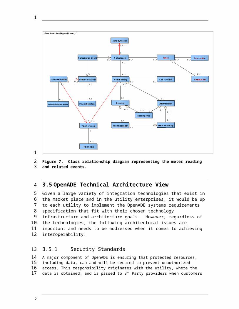
3.4.1 Meter Reading and Event ViewThis view is a center piece of ADE data architecture on meter reading and events. It provides a data structure for constructing the following messages:
MeterReading
ActivityRecord
1
1234567
89
10
1112131415
16
2

class Meter Reading and Ev ent
MeterReading ComFunction
Reading
ReadingQuality Interv alReading
Interv alBlock
ReadingType
MeterAsset
Activ ityRecord
EndDev iceEv ent
MeterSystemEv ent
Dev iceFunction
TimeSchedule
TimePoint
ScheduledEv ent
ScheduleParameters
Tok en Transaction
PointOfSale0..* 0..1
0..*
0..*
0..*
0..* 1
0..*
0..*
0..*
0..* 1.. * 1.. * 0..*
0..1
0..*
1
0..*
0..1
0..*
0..*
0..1
1
0..1
1
0..*
1
0..1
1 0..1
0..1
0..*
0..*0..* 0..* 0..*0..*
0..*
Figure 7. Class relationship diagram representing the meter reading and related events.
3.5 OpenADE Technical Architecture ViewGiven a large variety of integration technologies that exist in the market place and in the utility enterprises, it would be up to each utility to implement the OpenADE systems requirements specification that fit with their chosen technology infrastructure and architecture goals. However, regardless of the technologies, the following architectural issues are important and needs to be addressed when it comes to achieving interoperability.
3.5.1 Security StandardsA major component of OpenADE is ensuring that protected resources, including data, can and will be secured to prevent unauthorized access. This responsibility originates with the utility, where the data is obtained, and is passed to 3rd Party providers when customers authorize their use of specific utility data. To ensure that data is not provided to unauthorized parties, the following security measures are to be used.
(Content requires discussion with task force)
1
1
2
345678
91011121314
15
2

3.5.2 Service PatternsService naming standards are important to achieve a level of “plug & play” at the run time environment. It implies the semantics of the service and its operations.
The OpenADE services naming convention has the following rules:
o Information Object – Collection of entities to describe an object in a business context.
o Service Name – Service naming convention follows the information object in a business process for an interface definition.
o Operation Name – Operation name indicates a specific action that will be performed to the Information Object. Here is a list of operation naming patterns utilizing IEC 61989 verbs (See IEC61968-1 Specification for details):
The following verbs are used for service/operation provided by the master system that owns the Information Object to entertain the request for the specified action implied by the verb.
Create Change Cancel Close Delete
The following verbs are used for service/operation provided by systems that are interested in receiving the Information Object as the result of the specified action implied by the verb. This can be invoked by the master system or an intermediary to supply the Information Object.
Created Changed Closed Canceled Deleted
The following verbs are used for query type services provided by the master system of the Information Object.
Get Show Reply
The following verbs are not used within OpenADE. Subscribe Unsubscribe
1
1234
5
67
89
1011121314151617181920212223242526272829303132333435
2
3.5.3 Governance
Governance defines the rules by which parties participating in interoperability (integration, or data exchange) efforts can change the interfaces and components providing and consuming them, in order to maintain efficient operation. For OpenADE, governance includes guidelines recommended for addition or extension of standard interfaces, as well as modifications to or extensions to become part of the standard. (Content on this topic needs to be discussed)
3.5.3.1 ExtensionsThis section describes how extensions are to be made, to allow additional data elements to be added by individual implementations, as well as for the next version of the recommendation, so that existing providers and consumers can continue to operate with or without those additions.
(Content on this topic needs to be discussed)
1
1
234567
89
1011
12
2

4 Appendices
4.1 Terms and DefinitionsThis subsection provides the definitions of all terms required to properly interpret the OpenSG OpenADE SRS.
Term Definition
Advanced Metering Technology which allows two way communications between the utility and the meter. This communication enables the ability to analyze energy consumption resulting in more efficient demand response systems.
Advanced Metering Infrastructure (AMI)
The infrastructure built around advanced metering allowing the utility and consumer to communicate in real time with respect to energy consumption. Based on the information collected the utility is able to obtain an accurate reading of demands, while consumers are able to modify their usage to save energy.
Automated Meter Reading
Automated meter reading is a subcategory of AMI which allows for communication devices to transfer data from a meter to the utility or from a meter to the data management provider.
Business Service Provider
Software delivered over the internet as web services. The platform for integrating these web services is the enterprise service bus.
Daily Consumption The amount of energy a customer uses in a 24 hour period. This information is used to drive business intelligence solutions.
Energy Data Management
Analyzing meter data for consumption by backend systems. Often times these back end systems will measure load, calculate demand response, billing intervals, etc.
ESBEnterprise Service Bus. The ESB provides the features necessary for a service oriented architecture implementation by providing a place to host all of the web services.
IECThe International Electrotechnical Commission (IEC). The IEC TC57 maintains an electric utility focused information model called CIM (Common information model).
IEC 61968
International standards for Energy Distribution Managements Systems, respectively, specify a Common Information Model (CIM) for utility data exchange, Applications Programming Interfaces (API) for application integration (GID), and XML messaging standards.
Logical Data ModelA representation of an organization’s data based upon entities and attributes of those entities. A logical data model is often a logical representation of a business' integration or business requirements.
Meter Bus (M-bus) Allows for the interconnecting of many different utility measuring units (i.e. gas, electric, water, etc.) The M-Bus acts as the central station for these different utilities to communicate with.
Meter Data Management
A system for storing, processing, consuming and analyzing large quantities of meter data.
1
1
234
2

Term Definition
Smart GridThe term smart grid represents the digital upgrade of our distribution and long distance transmission grid allowing for increased energy efficiency as well as a boost in optimization of current systems.
SLA Service Level Agreement: the part of a service contract where the level of the services are agreed upon between two systems.
Smart Meters Meters with extra functionality that allow for more accurate and useful meter readings. This extra functionality allows the meter to collect usage data and transmit this data back to the utility over a network.
SOA
Service oriented architecture – The concept of grouping business functionality around business processes. These services are than packaged as interoperable services. A SOA architecture allows for the transmission of data between multiple systems as they participate in multiple business processes.
SOAP Simple Object Access Protocol (XML protocol) – A protocol for exchanging xml messages for web services in a service oriented architecture implementation.
Supervisory Control and Data Acquisition (SCADA)
SCADA systems monitor and control the electric power generation, transmission, and distribution.
UML Unified Modeling Language is a general purpose modeling language commonly used for object/data modeling.
WSDL Web Services Description Language is an xml format used to describe web services and the messages that interface with the web services.
XML Extensible Markup Language – general purpose markup language for creating custom mark-up languages.
XSD A description describing a specific xml document focusing primarily on the restraints and structure of that xml document.
Utility Sub Metering
An implementation that allows for a multi tenant property to bill tenants for individual energy usage. This is most commonly implemented in apartments and condominiums.
CIM Term Definition
ActivityRecord Records activity for an Asset, Location, Document, PowerSystemResource, Organization or ErpContact (e.g., operator, market participant, etc.) at a point in time. An activity may be for an event that has already occurred or for a planned activity. The PowerSystemResource relationship records events regarding the logical function being provided by the resource in the electrical network (independent of the particular asset providing the function). The Asset relationship records history about the particular equipment, independent of where it is currently being used in the electrical network. The Location relationship records events associated with the geographical location. The Customer relationship records history regarding the customer independent of the logical network or particular assets being used to serve the
1
1
2
2
CIM Term Definition
customer.
EndDeviceAsset
This type of AssetContainer performs one or more EndDevice functions. One type of EndDeviceAsset is a Meter Asset which can perform metering, load management, connect/disconnect, accounting functions, etc. Some EndDeviceAssets, such as ones monitoring and controlling air conditioner, refrigerator, pool pumps may be connected to a MeterAsset. All EndDeviceAssets may have communication capability defined by the associated ComFunction(s). An EndDeviceAsset may be owned by a consumer, a service provider, utility or otherwise.
IntervalBlock Used within a MeterReading to identify a time sequence of Readings of the same ReadingType.
IntervalReading
Data captured at regular intervals of time. Interval data could be captured as incremental data, absolute data, or relative data. The source for the data is usually a tariff quantity or an engineering quantity. Data is typically captured in time-tagged, uniform, fixed-length intervals of 5, 10, 15, 30, or 60 minutes. Interval Data is sometimes also called "Interval Data Readings" (IDR).
Location
The place, scene, or point of something where someone or something has been, is, and/or will be at a given moment in time. It may be the spatial location of an actual or planned structure or set of point-oriented structures (as a substation, structure, building, town, etc.), which may be defined as a point or polygon. It may also be the path of a underground or overhead conductor.
Meter This is generic logical meter object.
MeterAssetThe physical asset that performs the metering role of the ServiceDeliveryPoint. Used for measuring consumption and detection of events.
MeterAssetModel
Documentation for a type of a meter asset of a particular product model made by a manufacturer (Organisation). These types of meters are used to measure power consumption. There are typically many instances of an asset associated with a single asset model.
MeterReading Used to convey quantities that are measured by a meter.
MeterReadingPurpose
The purpose of the meter reading, such as initial reading, final reading, peridic reading, demand reading, etc. This information is often used to distinguish final and initial readings when there is a tenancy change at a service location.
MeterTypeAsset
Documentation for a generic meter that may be used for design purposes. Rather than being associated with CustomerMeter, it is associated with EnergyConsumer as it may be used for many applications, such as tie line metering, in addition to customer metering.
Reading Used to convey a specific value measured by a meter or other asset. Each Reading is associated with a specific ReadingType.
ReadingQuality The quality of a specific reading. Note that more than one Quality may be applicable to a given Reading Value. This field is not
1
2

CIM Term Definition
necessary unless problems or unusual conditions occur because Quality for each Reading Value is assumed to be 'Good' unless stated here otherwise.
ReadingType Used to identify the type of data that is conveyed by a specific Reading.
ServiceDeliveryPointThere can be multiple service points at a single ServiceLocation, each one identified as a ServiceDeliveryPoint. They deliver service in accordance with a CustomerAgreement.
A service point exists within a ServiceLocation and is used at the place where a meter may be installed. Properties include:
1
1
2
3
2