openflow-based aggregation mechanism for communication in
TRANSCRIPT

OpenFlow-based Aggregation Mechanism for
Communication in the Internet of Things
Shilpa Manda
A Dissertation
Presented to the University of Dublin, Trinity College
in partial fulfilment of the requirements for the degree of
Master of Science in Computer Science
(Future Networked Systems)
Supervisor: Stefan Weber
August 2019

Declaration
I, the undersigned, declare that this work has not previously been submitted as an
exercise for a degree at this, or any other University, and that unless otherwise stated,
is my own work.
Shilpa Manda
August 10, 2019

Permission to Lend and/or Copy
I, the undersigned, agree that Trinity College Library may lend or copy this thesis
upon request.
Shilpa Manda
August 10, 2019

Acknowledgments
I would like to take this opportunity to express my sincere gratitude to my supervisor
Dr. Stefan Weber, for his valuable guidance and motivation throughout the course
of this dissertation. I would also like to thank my mother, sister and Anish for their
support and encouragement during my course at Trinity.
Shilpa Manda
University of Dublin, Trinity College
Aug 2019
iii

OpenFlow-based Aggregation Mechanism for
Communication in the Internet of Things
Shilpa Manda
Master of Science in Computer Science(Future Networked Systems)
University of Dublin, Trinity College, 2019
Supervisor: Stefan Weber
Internet of Things(IoT) is a novel technology which polls data at high frequenciesand produces packets with small payloads. IoT devices make distinct measurementsthus producing heterogeneous in a small area. These densely deployed devices transmittheir data through the access network to store their values on the cloud, leading toflooding of packets in the access networks. IoT networks need mechanisms to handlethe scale issue in future. OpenFlow is a Software-Defined Networking(SDN) approachwhich separates the control plane from data plane offering centralised control. Flowaggregation gathers and aggregates data based on custom flows such as source addressand destination address, port numbers. This research aims at integrating support fordata aggregation in OpenFlow for communication in IoT devices. This study proposedthe design of an aggregator and deaggregator located at the boundary of the accessnetwork to aggregate IoT packets from edge networks into the access network anddeaggregate at the receiving end. The results of this research provide a detailed analysisof the percentage of packets reduced in the access network and the latency valuesobserved due to aggregation and how aggregation with OpenFlow can help overcomethe scale issue in IoT network.

Contents
Acknowledgments iii
Abstract iv
List of Tables ix
List of Figures x
Chapter 1 Introduction 1
1.1 Motivation and Aim . . . . . . . . . . . . . . . . . . . . . . . . . . . . 3
1.2 Dissertation Map . . . . . . . . . . . . . . . . . . . . . . . . . . . . . . 3
Chapter 2 State of the Art 5
2.1 Software Defined Networking . . . . . . . . . . . . . . . . . . . . . . . . 5
2.2 OpenFlow . . . . . . . . . . . . . . . . . . . . . . . . . . . . . . . . . . 7
2.2.1 OpenFlow Architecture . . . . . . . . . . . . . . . . . . . . . . . 7
2.2.2 Packet Processing in OpenFlow . . . . . . . . . . . . . . . . . . 9
2.2.3 Message Passing in OpenFlow . . . . . . . . . . . . . . . . . . . 9
2.3 Programming Protocol-Independent Packet Processors(P4) . . . . . . . 12
2.3.1 Abstract Forwarding Model . . . . . . . . . . . . . . . . . . . . 13
2.3.2 Operations in a P4 switch . . . . . . . . . . . . . . . . . . . . . 14
2.3.3 Language Components . . . . . . . . . . . . . . . . . . . . . . . 14
2.3.4 P4 Vs OpenFlow . . . . . . . . . . . . . . . . . . . . . . . . . . 15
2.4 SD WAN . . . . . . . . . . . . . . . . . . . . . . . . . . . . . . . . . . . 15
2.4.1 Cisco SD-WAN Architecture . . . . . . . . . . . . . . . . . . . . 16
2.4.2 Communication in Cisco SD-WAN . . . . . . . . . . . . . . . . 17
v

2.5 Why OpenFlow? . . . . . . . . . . . . . . . . . . . . . . . . . . . . . . 18
2.6 SDN in IoT Network . . . . . . . . . . . . . . . . . . . . . . . . . . . . 19
2.6.1 Features of IoT Traffic . . . . . . . . . . . . . . . . . . . . . . . 19
2.6.2 IoT Architecture based on SDN . . . . . . . . . . . . . . . . . . 20
2.7 Aggregation . . . . . . . . . . . . . . . . . . . . . . . . . . . . . . . . . 20
2.7.1 Types of Aggregation . . . . . . . . . . . . . . . . . . . . . . . . 21
2.7.2 Aggregation in IoT Networks . . . . . . . . . . . . . . . . . . . 22
2.8 Closely-related Projects . . . . . . . . . . . . . . . . . . . . . . . . . . 23
2.8.1 Using P4 Switches . . . . . . . . . . . . . . . . . . . . . . . . . 23
2.8.2 Wide-area Networks . . . . . . . . . . . . . . . . . . . . . . . . 23
2.9 Summary . . . . . . . . . . . . . . . . . . . . . . . . . . . . . . . . . . 25
Chapter 3 Problem Statement 27
3.1 Problem Formulation . . . . . . . . . . . . . . . . . . . . . . . . . . . . 27
3.2 Scope . . . . . . . . . . . . . . . . . . . . . . . . . . . . . . . . . . . . 28
3.3 Technical Challenges . . . . . . . . . . . . . . . . . . . . . . . . . . . . 29
3.4 Summary . . . . . . . . . . . . . . . . . . . . . . . . . . . . . . . . . . 30
Chapter 4 Design 31
4.1 Network Architecture . . . . . . . . . . . . . . . . . . . . . . . . . . . . 32
4.2 Enhancements to Existing Code-Base . . . . . . . . . . . . . . . . . . . 33
4.3 Software-Defined Aggregator Switch . . . . . . . . . . . . . . . . . . . . 33
4.4 Software-Defined Deaggregator Switch . . . . . . . . . . . . . . . . . . 35
4.5 Packet Design . . . . . . . . . . . . . . . . . . . . . . . . . . . . . . . . 35
4.5.1 IoT Packet Design . . . . . . . . . . . . . . . . . . . . . . . . . 35
4.5.2 Aggregated Packet Design . . . . . . . . . . . . . . . . . . . . . 36
4.5.3 Design Choices . . . . . . . . . . . . . . . . . . . . . . . . . . . 37
4.6 System Flow . . . . . . . . . . . . . . . . . . . . . . . . . . . . . . . . . 38
4.7 Summary . . . . . . . . . . . . . . . . . . . . . . . . . . . . . . . . . . 41
Chapter 5 Implementation 43
5.1 Simulator Choices . . . . . . . . . . . . . . . . . . . . . . . . . . . . . . 43
5.1.1 OMNeT++ . . . . . . . . . . . . . . . . . . . . . . . . . . . . . 43
5.1.2 NS-3 . . . . . . . . . . . . . . . . . . . . . . . . . . . . . . . . . 44
vi

5.1.3 Mininet . . . . . . . . . . . . . . . . . . . . . . . . . . . . . . . 45
5.2 Setup Environment . . . . . . . . . . . . . . . . . . . . . . . . . . . . . 45
5.2.1 Operating System . . . . . . . . . . . . . . . . . . . . . . . . . . 46
5.2.2 OMNeT++ . . . . . . . . . . . . . . . . . . . . . . . . . . . . . 46
5.2.3 INET Framework . . . . . . . . . . . . . . . . . . . . . . . . . . 46
5.2.4 OpenFlow . . . . . . . . . . . . . . . . . . . . . . . . . . . . . . 46
5.3 Aggregator . . . . . . . . . . . . . . . . . . . . . . . . . . . . . . . . . . 47
5.4 Deaggregator . . . . . . . . . . . . . . . . . . . . . . . . . . . . . . . . 49
5.5 Messages . . . . . . . . . . . . . . . . . . . . . . . . . . . . . . . . . . . 51
5.5.1 Feature Reply Message . . . . . . . . . . . . . . . . . . . . . . . 51
5.5.2 Flow Mod Message . . . . . . . . . . . . . . . . . . . . . . . . . 52
5.5.3 UDP Aggregate Message . . . . . . . . . . . . . . . . . . . . . . 52
5.5.4 OF Aggregate Message . . . . . . . . . . . . . . . . . . . . . . . 53
5.6 Source Code . . . . . . . . . . . . . . . . . . . . . . . . . . . . . . . . . 53
5.7 Summary . . . . . . . . . . . . . . . . . . . . . . . . . . . . . . . . . . 53
Chapter 6 Results and Evaluation 55
6.1 Setup and Measurements . . . . . . . . . . . . . . . . . . . . . . . . . . 55
6.2 Case 1: Access Network Traffic Measurements . . . . . . . . . . . . . . 58
6.2.1 Number of Destinations - 1 . . . . . . . . . . . . . . . . . . . . 58
6.2.2 Number of Destinations - 2 . . . . . . . . . . . . . . . . . . . . 59
6.2.3 Number of Destinations - 5 . . . . . . . . . . . . . . . . . . . . 60
6.3 Case 2: Latency Measurements . . . . . . . . . . . . . . . . . . . . . . 61
6.3.1 Number of Destinations - 1 . . . . . . . . . . . . . . . . . . . . 62
6.3.2 Number of Destinations - 2 . . . . . . . . . . . . . . . . . . . . 63
6.4 Discussion . . . . . . . . . . . . . . . . . . . . . . . . . . . . . . . . . . 65
Chapter 7 Conclusion and Future Works 67
7.1 Use Cases . . . . . . . . . . . . . . . . . . . . . . . . . . . . . . . . . . 67
7.1.1 Irish Water Meters . . . . . . . . . . . . . . . . . . . . . . . . . 67
7.1.2 Applied to TCD’s Campus . . . . . . . . . . . . . . . . . . . . . 68
7.2 Conclusion . . . . . . . . . . . . . . . . . . . . . . . . . . . . . . . . . . 68
7.3 Future Works . . . . . . . . . . . . . . . . . . . . . . . . . . . . . . . . 69
vii

Bibliography 71
Appendices 74
viii

List of Tables
5.1 Comparison of Network Simulators . . . . . . . . . . . . . . . . . . . . 54
6.1 Parameters Considered to Generate Exhaustive List of Test Cases . . . 56
ix

List of Figures
1.1 IoT Communication without Packet Aggregation . . . . . . . . . . . . 2
2.1 Layers of SDN Architecture . . . . . . . . . . . . . . . . . . . . . . . . 6
2.2 Main Components of an OpenFlow Switch . . . . . . . . . . . . . . . . 8
2.3 Packet Processing Steps in a OpenFlow Switch . . . . . . . . . . . . . . 10
2.4 Message Passing in an OpenFlow Switch during Initialisation Phase . . 11
2.5 Message Passing in an OpenFlow Switch during a Packet Miss . . . . . 12
2.6 P4 Switch Architecture . . . . . . . . . . . . . . . . . . . . . . . . . . . 13
2.7 Cisco SD-WAN Architecture . . . . . . . . . . . . . . . . . . . . . . . . 16
2.8 Messages Exchanged during On-boarding of a New vEdge Router in
Cisco-SDWAN[13] . . . . . . . . . . . . . . . . . . . . . . . . . . . . . . 18
2.9 Summary of Papers with Timeline and Section References . . . . . . . 25
2.10 Summary of Technologies with Issues and Benefits . . . . . . . . . . . . 26
3.1 Proposed Solution for densely deployed IoT devices . . . . . . . . . . . 28
4.1 Network Architecture . . . . . . . . . . . . . . . . . . . . . . . . . . . . 32
4.2 Architecture of an Aggregator Switch . . . . . . . . . . . . . . . . . . . 34
4.3 IoT Packet Design . . . . . . . . . . . . . . . . . . . . . . . . . . . . . 36
4.4 Aggregated Packet Design . . . . . . . . . . . . . . . . . . . . . . . . . 36
4.5 Packet Flow . . . . . . . . . . . . . . . . . . . . . . . . . . . . . . . . . 38
5.1 Process Flow of an Aggregator Switch . . . . . . . . . . . . . . . . . . 47
5.2 Process Flow of a Deaggregator Switch . . . . . . . . . . . . . . . . . . 50
5.3 Feature Reply Message . . . . . . . . . . . . . . . . . . . . . . . . . . . 51
5.4 Flow Mod Message . . . . . . . . . . . . . . . . . . . . . . . . . . . . . 52
x

5.5 UDP Aggregate Message . . . . . . . . . . . . . . . . . . . . . . . . . . 53
5.6 OF Aggregate Message . . . . . . . . . . . . . . . . . . . . . . . . . . . 53
6.1 Phases of Testing . . . . . . . . . . . . . . . . . . . . . . . . . . . . . . 57
6.2 Number of Sources:10, Number of Destinations:1 . . . . . . . . . . . . . 58
6.3 Number of Sources:30, Number of Destinations:1 . . . . . . . . . . . . . 59
6.4 Number of Sources:50, Number of Destinations:1 . . . . . . . . . . . . . 59
6.5 Number of Sources:10, Number of Destinations:2 . . . . . . . . . . . . . 60
6.6 Number of Sources:30, Number of Destinations:2 . . . . . . . . . . . . . 60
6.7 Number of Sources:10, Number of Destinations:5 . . . . . . . . . . . . . 61
6.8 Latency measurements: Sources -1,Destinations -1 . . . . . . . . . . . . 62
6.9 Latency measurements: Sources -10,Destinations -1 . . . . . . . . . . . 63
6.10 Latency measurements: Sources -1,Destinations -2 . . . . . . . . . . . . 64
6.11 Latency measurements: Sources -10,Destinations -2 . . . . . . . . . . . 64
6.12 Comparison of Mean Latency(us) for 1 source . . . . . . . . . . . . . . 65
6.13 Comparison of Mean Latency(us) for 10 sources . . . . . . . . . . . . . 65
xi

Chapter 1
Introduction
With the continued progress in the Internet of Things (IoT) and the resulting large-
scale deployment of IoT devices, the amount of data transferred by these devices over
the network has increased substantially. In contrast to the profile of traditional file-
based transmissions, the communication of IoT devices consists of an enormous number
of transmissions of small payloads. Traffic generated by IoT devices exhibits several
characteristics that set it apart from generic traffic such as the retrieval of web pages
or the streaming of videos. Individual IoT devices may produce data at irregular or
periodic frequencies that are transferred through the Internet to the cloud infrastruc-
ture for collection, analysis, and interpretation. The number of IoT devices on the
Internet is expected to increase exponentially, resulting in enormous amounts of small
data messages flooding the network elements between widely-distributed IoT devices
and semi-centralised cloud infrastructure components.
The current IoT network without data aggregation is shown in figure 1.1. The IoT
devices are located at the edge network and communicate to the sink nodes or cloud
through the access network. Each IoT device polls data at different frequencies and
transmits this data continuously to the cloud thus generating a large amount of traffic
at the access layer. This network does not scale well and the access network will be
flooded with packets when the number of IoT devices would grow exponentially due to
dense deployment in the near future. Thus, IoT paradigm has become a reality and is
deeply integrated into our communication system[1][2].
With an exponential increase in the number of network devices, greater flexibil-
1

Figure 1.1: IoT Communication without Packet Aggregation
ity and efficient management and control mechanisms are needed for an end-to-end
functioning of the entire network. OpenFlow is a software-defined networking control
protocol to segregate the control plane from the forwarding plane in network elements,
providing flexibility and easier implementation of network-wide packet forwarding poli-
cies. Thus, programmability of the data and control plane with a standardisation like
OpenFlow provides an optimised technique for packet transmission.
The vast amount of traffic generated calls for mechanisms to aggregate data which
belong to a particular flow and contain an overlap of packet data. IoT messages have
small payloads as compared to header data, and the overlap between packet header
data to the same destination becomes a considerable overhead for aggregation. Thus,
data aggregation mechanisms can help to reduce the processing in the access network.
IoT is the next big technological revolution and will bring in the paradigm shift
to the way we work, live and entertain ourselves. This novel technology has the po-
tential to transform every sphere of human life but also poses a great challenge to
handle the enormous amount of data generated on the network. Thus, the efficient
handling of packets and smooth communication without flooding is essential for IoT
to be successful.
2

1.1 Motivation and Aim
The three technologies mentioned in the above section: OpenFlow, Data Aggregation
and Internet of things(IoT) form the basis of this project. The problems of IoT networks
can be solved using aggregation and programmable networks. Thus, the basic idea of
integration of the three technologies to solve the real-world problem motivated me to
choose ”OpenFlow-based Aggregation Mechanisms for Communication in the Internet
of Things” as my dissertation topic.
Traditionally, the network elements of the Internet were designed to forward indi-
vidual data messages from a source to a destination without reacting to the content of
any of the messages that pass through them. Software-defined Networking (SDN) offers
the opportunity to configure network elements to react to traffic flows and change the
behavior of network elements based on a strategy directed by a control plane. Thus,
this research aims at:
1. Integrating support for aggregation of network traffic from IoT devices into Open-
Flow.
2. Addressing the challenge of the flooding of the Internet infrastructure with the
vast number of small messages.
3. Analyse the latency values of packets and reduction in the percentage of access
network traffic as a result of aggregation.
1.2 Dissertation Map
The dissertation is structured into seven chapters with focus areas as described below:
• Chapter 1: Introduction- This chapter gives a brief introduction about the
current IoT architecture and how OpenFlow and Aggregation can be used to
solve the scale issue in an IoT network in the near future. It also discusses the
motivation and aims of the project.
• Chapter 2: State of the Art- This chapter talks in detail about the three
technologies used in this project: SDN which includes OpenFlow, P4 and SD-
3

Wan, Aggregation and Internet of Things. In addition to this, it also lists other
closely related previous work on this topic.
• Chapter 3: Problem Statement- This chapter gives an abstract view of the
solution along with the scope and technical challenges faced during the project
execution.
• Chapter 4: Design- The design chapter focuses on the network architecture
used for experimentation, the design modifications in the OpenFlow switch and
controller. It also shows the design aspects of the aggregator, deaggregator and
the packets used for research. Lastly, it depicts the complete flow of packets in
the end-to-end system.
• Chapter 5: Implementation-This chapter starts by comparing the different
simulators which were available for the thesis and which best suited the sce-
nario. Then it talks about the setup environment, the detailed implementation
of different modules in the aggregator and deaggregator. Finally, it shows the
implementation of modified and new messages introduced for this project.
• Chapter 6: Results and Evaluation- In this chapter, a thorough analysis
of the latency of packets in the network and the percentage of reduction in the
packets in the access network is done. Results are depicted in graphs along with
detailed discussion.
• Chapter 7: Conclusion and Future Works- Finally, this chapter lists the
conclusions drawn from the research and how this work can be further extended.
4

Chapter 2
State of the Art
This chapter starts with a detailed description of the different technologies involved in
this project: SDN, Aggregation and IoT. It further expands on different implementa-
tions of SDN, namely, OpenFlow, Programming Protocol-Independent Packet Proces-
sor (P4) and Cisco SD-WAN (Software-Defined Wide Area Networks), and comparison
amongst them with respect to this dissertation. Sections 2.6 and 2.7 talk about how
IoT traffic is different from traditional network traffic and which aggregation mecha-
nism is best suited for our project. Lastly, section 2.8 describes and analyses the closely
related projects to our dissertation
2.1 Software Defined Networking
With the introduction of network programmability, traditional networks have become
highly flexible, dynamic, and easily manageable. Higher performance, early detec-
tion of errors, and faster extensibility of switches and routers with new features are
some of the significant benefits of a programmable network. Such a network which
can be controlled using software is called a software-defined network. SDN provides
a clear separation of duties in network elements, thus providing efficient management
of networks. Different architectures of SDN have been proposed and implemented in
products namely OpenFlow switches, SD-WAN routers and P4 switches. The archi-
tecture of a software-defined network can be divided into Device Layer, Data Layer,
Control Layer, and Application Layer, as shown in figure 2.1.
5

Figure 2.1: Layers of SDN Architecture
• Device Layer : The device layer of the SDN architecture consists of network
infrastructure, for example, IoT devices, gateways. These devices can be physical
or virtual in nature. The edge routers may be present at the boundary of the
device layer and data layer, which connects the two layers together and forwards
the data from the device layer to the data layer.
• Data Layer : The data layer of an SDN network consists of programmable
and non-programmable routers and switches. An SDN network supports the co-
existence of both software programmed components with non-programmable de-
vices. These elements are specialised in forwarding and do not make any routing
decisions. The southbound interfaces ( Application interfaces ) form the bridge
between the control plane and the underlying network components in the data
plane. OpenFlow is the most widely accepted and deployed open southbound
standard for SDN.[3]
• Control Layer : The control layer of an SDN network consists of SDN con-
trollers, orchestration devices, and network hypervisors. SDN controllers or the
network operating system(NOS) have a complete view of the network and make
routing decisions based on configured policies for the data layer devices. They
6

thus form the brain of the network. The orchestration devices allow automatic
deployment, configuration and management of a large number of network com-
ponents, thus handling scale scenarios efficiently. Besides, to enable resource
sharing among distinct virtual machines, network hypervisors in an SDN allow
the cooperative (sequential or parallel) execution of applications developed with
different programming languages or conceived for diverse control platforms. It
offers interoperability and portability in addition to the typical functions of net-
work hypervisors [3].
• Application Layer : The application layer consists of network applications for
different applications such as traffic engineering, measurements, monitoring, se-
curity. The management plane also consists of high-level programming languages
which are powerful tools for implementing and providing abstractions for impor-
tant properties and functions of SDN such as network-wide structures, distributed
updates, modular composition, virtualisation, and formal verification.
2.2 OpenFlow
OpenFlow[4] is the most widely accepted SDN standard for communication between
the control and data plane.OpenFlow is a flow-oriented protocol and has switches and
ports abstraction to control the flow. It is a protocol that enables the implementation
of the SDN concept in both hardware and software.[5]. In SDN, there is a controller in
the control plane, which makes all the routing decisions and manages the OpenFlow
switches in the data plane. The OpenFlow switches contain multiple flow tables which
are populated by the controller based on configured policies. These flow table entries
are then used by the switches to forward the data packets in the network[6]. Thus, by
decoupling control plane and data plane, SDN approach simplifies network management
and speeds up network innovations and standard protocols such as OpenFlow simplify
the implementation of programmability in the network.
2.2.1 OpenFlow Architecture
The OpenFlow network architecture consists of OpenFlow controllers and OpenFlow
switches which communicate using OpenFlow protocol as shown in figure 2.2.
7

Figure 2.2: Main Components of an OpenFlow Switch
• OpenFlow Switch : An OpenFlow switch consists of a secure control channel,
one or more match action tables, group tables and an optional packet buffer.
The flow tables are referred to as match action tables in the figure 2.2. The flow
tables and group tables together constitute the data pipeline of the switch. Each
flow table contains a set of flow entries; each flow entry consists of match fields,
counters, and a set of instructions to apply to the matching packets[7]. The group
table stores the group entries where a list of action buckets are present for every
entry based on the type of group. These actions in the action bucket are applied
to the packets sent to that particular group. A configurable packet buffer stores
the incoming data packets for processing and forwarding to its destination.
• Controller : An OpenFlow controller controls and manages one or more Open-
Flow switches in an SDN. It is a centralised controller which maintains the entire
topology information and monitors the entire status of the network[8]. Using the
OpenFlow protocol, the controller can add, update, and delete flow entries in
flow tables, both reactively (in response to packets) and proactively [7].
• Match Action Tables : The controller populates the flow-entries in the flow
table of an OpenFlow switch which consists of network operations or simple
8

actions to be applied for the matching packets. Actions included in instructions
describe packet forwarding, packet modification, and group table processing [7].
A chain of flow tables can be configured in a pipeline to apply one or more
forwarding rules to the incoming packets. Timeouts are also configured for every
flow entry which determines the expiry time of a flow-entry in a switch. Priority
values are used to match the precedence values of the flow entries.
2.2.2 Packet Processing in OpenFlow
Figure 2.3 represents the flow of packets in an OpenFlow 1.0.0 switch. Every packet
in the network consists of headers and payload field. The header fields of a packet
are used to find the corresponding flow entries in the flow table and actions are taken
accordingly. The order of processing of a network packet in an OpenFlow switch is as
follows:
• Packet Parsing system :
The dataplane packet first enters the Packet Parsing System where the headers
of the packet are extracted. The matching criteria are extracted from the headers
and are sent to the Packet Matching System. Packet match criteria for look-ups
is dependent on the kind of packet and is composed of different header fields such
as Ethernet source address, destination IPv4 address.
• Packet Matching system :
The match criteria are then sent to the Packet Matching System. This matches
the look-up keys with the match fields of the flow table entries to search for the
corresponding action. In case there is a match, the respective action is executed,
else, the packet is forwarded to the OpenFlow controller using a Packet-In Mes-
sage. The controller responds with a Packet-Out Message and Flow-Mod Message
which is used to update the flow entries in the flow tables.
2.2.3 Message Passing in OpenFlow
Figure 2.4 shows the sequence of messages exchanged between the OpenFlow con-
troller and OpenFlow switch during the initialisation phase. The controller and switch
9

Figure 2.3: Packet Processing Steps in a OpenFlow Switch
establish a secure and reliable communication channel over Transport Control Protocol
(TCP).
The OpenFlow switch and controller initially exchange hello and syn messages as
a part of TCP 3-way handshake. Then the controller sends a query message called
Features Request Message to query about the state configuration parameters from the
switch. The switch acknowledges the message and responds with a Feature Reply Mes-
sage. This message contains the configuration parameters of the switch; for example,
the number of flow tables supported, buffer size, spanning tree support. The controller
acknowledges this message and responds with a Flow-Mod Message. A Flow-Mod Mes-
sage contains parameters specific to a flow entry in a flow table, for example, timeouts,
buffer identifiers, input ports, output ports, priority values. This message is further
10

Figure 2.4: Message Passing in an OpenFlow Switch during Initialisation Phase
acknowledged by the switch. Thus, initialisation of an OpenFlow switch is complete.
Figure 2.5 shows the sequence of messages exchanged between an OpenFlow switch
and controller during a packet miss.
In scenarios where a flow entry is not found in the flow table, the switch sends a
Packet-In Message to the controller containing the packet details and buffer details
where the packet is buffered. The controller acknowledges this message and responds
with a Packet-Out Message. This message instructs the switch to take appropriate
action with the data packet. The controller also populates the complete route via a
Flow-Mod Message in the flow table of the switch.
11

Figure 2.5: Message Passing in an OpenFlow Switch during a Packet Miss
2.3 Programming Protocol-Independent Packet Pro-
cessors(P4)
On the one hand, where OpenFlow defines a standard protocol for communication be-
tween the forwarding and the control plane, P4 removes the dependence on protocols
itself. P4 is a high-level language used to program switches which are not tied to any
specific network protocols [9]. It is maintained by P4 Language Consortium[10]. There
are three main features of a P4 processor:
1. Operation of P4 switches is independent of the underlying network protocol.
2. The switches can be reconfigured in the way they process the packets after being
deployed in the field.
3. The processing functionality of the packets is independent of the underlying hard-
12

ware [9].
2.3.1 Abstract Forwarding Model
Figure 2.6: P4 Switch Architecture
P4 is a high-level language which is designed to across different forwarding devices
and technologies, thus providing a protocol-independent and target-independent pro-
cessor. The abstract forwarding model of a P4 switch consists of a programmable
parser, match action tables comprising of forwarding rules which make up the ingress
and egress pipeline. The P4 Switch architecture is shown in figure 2.6.
A programmable parser in P4 allows the switch to run multiple target-independent
programs which are mapped using the compiler. The underlying hardware can range
from fast ASIC-based switches to slow software-based ones, thus satisfying the primary
goals of a P4 switch[11]. A user-supplied P4 program is compiled by the P4 compiler.
This generates a target-specific binary which controls the entries in the match action
13

tables. The match action tables and parsers are divided between ingress and egress
pipelines. A data packet first enters the parser of the ingress pipeline. The parser
extracts the headers and forwards them to the match action tables. These tables find
the corresponding action based on lookup keys and process the data in a sequence of
match action tables. The packet is reconstructed at the deparser of the egress pipeline
and then forwarded to the output channel.
2.3.2 Operations in a P4 switch
There are two major operations for a P4 switch to forward packets in the network
smoothly: configure and populate[9].
The configure operation step performs the following functionalities:
1. configures the programmable parse
2. determine the order execution of the match action tables
3. set the header fields to be executed under each match action stage.
The match action entries specified during the configuration operation are populated
during the populate operation. Thus, this operation determines the policies applied
during the forwarding of packets.
2.3.3 Language Components
There are five main components of P4 language:
• Headers A header consists of multiple fields which have a set order and structure.
The size of field values in terms of width and the constraints on these values are
also defined as a part of the header.
• Parsers A programmable parser in P4 switches identify valid headers. These
headers are then extracted and processed in a particular sequence.
• Tables Tables match any subset of header fields parsed by the parser. The fields
matched in the header are reconfigurable in a P4 switch and are not fixed in
nature. The P4 table abstraction specifies the fields to match on (such as source
14

or destination IP or MAC address), the match policy (such as exact match,
ternary matches with wildcards, or longest prefix match), the size of the table to
assist the compiler back-end and the allowed set of actions for this table[12].
• Actions The match + action tables consist of various complex actions which
are based on simpler protocol-independent primitives. On a successful match,
the corresponding action such as drop, flood, mark, etc. are executed from the
tables.
• Control Program A control program determines the order of execution of match
action tables. In a P4 switch, the order of execution of match action tables can
be serial or parallel[9].
2.3.4 P4 Vs OpenFlow
1. The parser in OpenFlow is fixed whereas P4 switches support a programmable
parser where new header fields can be defined.
2. Complex actions can be defined which are composed of protocol-independent prim-
itives and the operation of P4 switches is independent of the underlying hardware and
network protocols.
3. A P4 switch can have the match and action tables in series or parallel whereas
in OpenFlow switches the match action tables are always in series.
2.4 SD WAN
SD-WAN is the application of SDN technology to wide-area networks such as LTE,
MPLS, or the Internet. It separates the data and control plane, which is managed
by a management layer, usually on the cloud. SD-WAN technology is independent of
the underlying transport protocol. It also provides additional network services such
as WAN optimisation, cloud security. The endpoints in an SD-WAN environment can
be cloud, data-centre, branch, or a campus, thus providing with endpoint flexibility as
well.
15

Increased network traffic with the tremendous growth of the IoT, software as a
service (SaaS) and cloud applications has led to the application of SDN principles to
the WAN network thus providing greater security, flexibility, and optimisation at the
WAN level.
2.4.1 Cisco SD-WAN Architecture
The Cisco SD-WAN solution comprises of four planes: data, control, management, and
orchestration plane, as shown in figure 2.7[13].
Figure 2.7: Cisco SD-WAN Architecture
• Orchestration Plane: The orchestration plane enables automation of authen-
tication and on-boarding of new devices in the network, thus enabling scale de-
ployments. The vBond orchestrator performs the orchestration of the network in
Cisco SD-WAN solution.
• Management Plane: The management plane consists of vManange, which
helps in easy monitoring, configuration, and maintenance of the network compo-
nents in the underlying control and data plane.
16

• Control Plane: The control plane consists of the vSmart controller which con-
trols the vEdge routers in the data plane and distributes the routes and policy
information to the routers. It communicates to the vEdge routers securely over
Overlay Management Protocol(OMP). The OMP protocol is used to exchange
control information such as route prefixes, policies, cryptographic keys, etc. over
Transport Layer Security(TLS) and Datagram Transport Layer Security (DTLS)
between the vSmart controller and vEdge routers.
• Data Plane: The data plane consists of vEdge routers which forward the pack-
ets which sits at a physical site or in the cloud and provides secure data plane
connectivity among the sites over one or more WAN transports[13].
2.4.2 Communication in Cisco SD-WAN
The vEdge routers communicate securely to vSmart and vManage over DTLS and
TLS. vEdge routers establish IPSec tunnels amongst themselves for communication
over both TLS and DTLS. Loss of packets, jitter, and latency, are detected by Bidirec-
tional Forwarding Detection(BFD), which is enabled by default over IPSec ( Internet
Protocol Security). When a new vEdge router joins a network, the following steps take
place:
1. vEdge router is first authenticated by vBond orchestrator and obtains the IP ad-
dress of vSmart and vManage from it over a secure channel. The vBond also informs
the vManage and vSmart about the new vEdge.
2. The vManage then authenticates the vEdge router and send the full configura-
tion file of vEdge router if available.
3. The vSmart then authenticates the vEdge and establishes an OMP session be-
tween them for the exchange of control information such as routes, policies, etc.
4. Lastly, the vEdge establishes IPSec tunnels with other vEdge routers. The message
passing is depicted in figure 2.8.
17

Figure 2.8: Messages Exchanged during On-boarding of a New vEdge Router in Cisco-SDWAN[13]
2.5 Why OpenFlow?
On the one hand, P4 offers routing independent of target hardware and protocol; it is
still an evolving concept in the networking field. There have been no significant de-
ployments in production yet. Whereas OpenFlow, on the other hand, is a standardised
protocol used for communication between the control and data plane and OpenFlow
switches and agents have been widely adopted. This protocol has been repeatedly
tested by enterprises and researchers over the years on both simulators and test-beds.
P4 simulators and controllers for testing and management are still under development.
The first version of P4Runtime [14] which is used to control the running P4 forwarding
element is relatively a new concept released in March 2019.
Cisco SD-WAN routers on other hand use OMP protocol, which is the heart of
Viptella overlay routing environment. It is used for establishing and maintaining the
control plane, whereas OpenFlow, promoted by Open Networking Foundation (ONF)
is implemented by many network vendors. Due to the reasons mentioned above, Open-
Flow is found to be suitable for development and testing of large scale topologies with
18

heavy IoT traffic.
2.6 SDN in IoT Network
Traffic generated by the IoT network has many features which set it apart from the
traffic generated by the access network. Due to the vast number of packets generated,
network resources such as bandwidth, channel utilisation, and throughput become all
the more important in this case. With the use of SDN technologies in an IoT network,
these resources can be optimised along with greater flexibility and management in the
network.
Flow-Sensor[15], Sensor OpenFlow[16], and SDWN (Software-Defined Wireless Net-
works) [17] are some of the previous works to support SDN technologies in the wireless
domain. One recent effort to introduce SDN technologies to IoT network was made
in [18], which proposed a layered architecture with an SDN controller promoting pro-
grammability and efficient communication among heterogeneous devices.[19] proposed
a programmable SDN switch based on P4, deployed in an IoT network.
2.6.1 Features of IoT Traffic
Some of the basic features of traffic generated by the majority of IoT network devices
are:
1. A large number of small packets of data generated by sensors distributed over an
area.
2. Packets containing redundant information generated at real-time at regular or
irregular frequencies.
3. Heterogeneous data generated by different kinds of devices deployed in a small
area as opposed to homogeneous data generated by wireless sensor networks.
4. Packets containing small payloads of data such as sensor readings, live messages
generated at a very high frequency.
5. IoT network devices such as smart meters, actuators, and smart meters are
resource-constrained devices which have limited energy and memory. They are
19

usually battery-operated devices with limited power thus requiring lightweight
communication technology[20].
2.6.2 IoT Architecture based on SDN
[18] proposed a layered SDN based architecture for IoT network. The network consists
of four layers: Device Layer, Communication Layer, Computing Layer, and the Service
Layer.
• Device Layer: The device layer consists of densely deployed IoT devices. These
devices communicate with the gateways or routers in the communication layer
using device interface drivers. The sink devices at the edge of the communication
and device layer aggregate and cache the data obtained from the IoT devices.
• Communication Layer: This layer consists of gateways and routers, which
forward the data from the remote IoT devices. These also perform application-
specific data processing and local analysis. Protocol converting, node manage-
ment, security. Data storing and caching and data forwarding are the main
functions of the communication layer.
• Computing Layer: The computing layer consists of SDN controllers which for-
ward and process the data received by the IoT devices. Equipment management,
IoT service management, security management, topology management, opera-
tion, and maintenance are the main functions of the computing layer. The SDN
controller communicates to the gateways and routers using the South Bound
Interface (SBI) driver on the controller.
• Service Layer: IoT services, for example, smart homes, intelligent transport,
are built at the service layer by operators and developers[21][22].
2.7 Aggregation
IoT network consists of densely deployed devices such as sensors, actuators, smart me-
ters, which emit packets at high and irregular frequency containing redundant data.
Thus, the huge number of packets generated can flood the access network and consume
20

a high percentage of the bandwidth leading to degradation of the network performance.
In a scenario where IoT devices are densely deployed, and quite a few short packets are
transmitted in WAN, the number of processed packets per second (pps) increases at
the forwarding routers thus increasing the power consumption, processing delays, and
packet loss. [20]. The overhead associated with every packet, for example, Ethernet
frame header, IP header, also adds to the number of bytes transmitted leading to inef-
ficient bandwidth usage. Thus, different aggregation mechanisms focus on combining
the packets to reduce the number of packets transmitted in the network and increasing
the lifetime of the network components.
2.7.1 Types of Aggregation
Data aggregation aims at gathering and aggregating data in an energy-efficient manner
to increase the lifetime of the network. The number of packets that could be aggregated
together depends if the network is delay-tolerant or delay-intolerant and the acceptable
latency value at the destination. This process, when applied globally at intermediate
nodes, is referred to as in-network data aggregation[23]. There are two types of in-
network aggregation:
• with size reduction: In-network aggregation with size reduction refers to the
process of combining and compressing the data packets received by a node from
its neighbours to reduce the packet length to be transmitted or forwarded towards
the sink. This is suitable in a network having components emitting homogeneous
packets containing redundant data.
• without size reduction: In this scenario, the value of the data is not processed, and
the data received from different sources are merged into a single packet depending
on the aggregation factor. This process can be applied to heterogeneous data as
the value of the data is not processed, and the packets are aggregated depending
on the destination[23].
Flow-based aggregation[24][25] refers to the gathering and merging data which be-
long to a particular flow. A flow can be characterised one or more attributes of a
network packet such as a TCP connection or a UDP stream described by for exam-
ple source and destination IP addresses, source, and destination port numbers, or the
21

protocol number. For flow-based monitoring, a flow is identified by source-destination
addresses, source-destination port numbers, and protocol[26]. A network packet com-
prises of a header which contains the metadata information and payload which is the
information being conveyed. Network packets belonging to a particular flow has several
overlapping elements such as Ethernet frame header, source or destination IP addresses.
In scenarios where the payload size is very small, the header information makes up the
majority of the bits in a packet and constitute the overhead. This overhead can be
minimised by combining the packets which belong to a particular flow, thus minimising
the packets in the network.
2.7.2 Aggregation in IoT Networks
IoT wide area network consists of heterogeneous data from different kinds of sources.
In [27], packet aggregation in a multi-hop wireless sensor network was studied, where
the nodes form a tree structure. The parent nodes receive data from the child nodes,
aggregate their data to the received packets, and send the data upwards towards their
parent until finally, it reaches the sink node. [20] states the WAN requirements of IoT
network and proposed an aggregation and disaggregation scheme based at Constrained
Application Protocol (CoAP) layer with IP and UDP at network and transport layer
respectively. The WAN IoT traffic requirements include:
• Aggregation and deaggregation of packets with different destinations, thus sup-
porting non-unidirectional aggregation of data.
• Selective aggregation of data depending on the types of applications. For exam-
ple, in applications requiring real-time transmission of data, uniform aggregation
can lead to increased latency, which is not acceptable.
• Nodes which support aggregation capabilities can coexist with those that do not,
thus allowing the adoption to node capability.
As IoT devices have limited power and memory[28], energy-optimal aggregation schemes
not only reduce packets through aggregation, but also increase the lifetime of network
components and this would help us solve the scale issue in IoT network in an optimal
manner[29]
22

2.8 Closely-related Projects
This section details the closely related projects where aggregation of data is performed
in an IoT network using SDN approaches.
2.8.1 Using P4 Switches
P4 switches have a programmable control plane and data plane and offer high flexibility
in packet switching based on header manipulation using P4 language. [19] proposes
a novel approach to aggregation and deaggregation of IoT traffic in P4 switches and
claim to achieve speeds up to 100Gbps per port. This translates to 6.5Tbps in a 64
port switch. The proposed functionality was implemented in EdgeCore P4 switches,
and the IoT devices were simulated using a Spirent Test Centre[19].
• The Spirent Test Centre provides the source for IoT traffic at rates as high as
100Gbps per line rate. These IoT packets are sent to the first EdgeCore P4
switch. The first switch on receiving N IoT messages aggregates them together
over UDP.
• A new flag header was introduced between UDP header and payload. This flag
header contains a type field to distinguish an IoT packet from an aggregated
packet.
• The first P4 switch extracts the UDP payloads of the incoming IoT messages,
stores them in a register and constructs an aggregated packet by introducing an
aggregated header which consists of N payloads collected from IoT packets.
• These aggregated packets are transported to the other P4 switch which deaggre-
gates them and transports them back to the Spirent Test Centre which also acts
as the sink for the packets.
2.8.2 Wide-area Networks
[20] proposed aggregation and deaggregation of IoT traffic in a wide area network.
Wide-area network consists of IoT devices which have various communication patterns.
23

Aggregation and deaggregation of IoT traffic in wide area networks should support the
following requirements:
1. Different types of traffic destined for various destinations and coming from mul-
tiple sources.
2. Selective aggregation of real-time or uniform traffic based on applications
3. WAN should support network components which can handle both aggregated
and non aggregated traffic.
The tests were performed in a network consisting of four types of nodes:
1. Ingress Nodes or IoT nodes: These devices emit various kinds of IoT traffic
at different frequencies. For example, IoT gateways and home gateways.
2. Intermediate Nodes which support Aggregation: These devices aggregate
the traffic received based on the destination within the same autonomous sys-
tem and forward the traffic to the other WAN routers which do not support
aggregation.
3. Intermediate Nodes which do not support Aggregation: These routers
form the backbone of a WAN and only forward the received packets. They do not
have any aggregation or deaggregation capabilities. A flag is used to distinguish
between the two kinds of intermediate nodes.
4. End Nodes: These nodes deaggregate the received packets and are similar to
the border routers with other ISPs( Internet Service Providers) or data centres.
The aggregation and deaggregation of network traffic are limited to the routers or
gateways located at the borders of different types of network. This enables to reduce
the power consumption of the core devices in the WAN and increases the lifetime
of the network. The process of aggregation is reversible and does not change the
information in the payload. [20] proposed the creation of overlay networks based on
the kinds of information emitted by the IoT devices. Different logical networks can
handle information with different requirements.
24

2.9 Summary
Figure 2.9: Summary of Papers with Timeline and Section References
Figure 2.9 depicts a few of the closely related works under the respective topics
with the timeline. The figure lists research papers on SDN, which covers OpenFlow as
well.
There has been very less research in the areas overlapping SDN and aggregation
of packets over the network. The closely related projects section in the figure lists the
projects on P4 switches, aggregation and IoT. However, no work has been done on the
integration of OpenFlow with aggregation and IoT. Thus, ”OpenFlow-based Aggrega-
tion Mechanisms for Communication in the Internet of Things” forms an entirely new
area of research.
25

Figure 2.10: Summary of Technologies with Issues and Benefits
Figure 2.10 summarises the main features of OpenFlow, IoT and aggregation. The
benefits offered by SDN and aggregation can be used to overcome the scale issue in
IoT. This idea now forms the basis of this dissertation, and further chapters explain
how this can become a reality with our implementation.
26

Chapter 3
Problem Statement
This chapter is divided into three sections. Section 3.1 talks about the problem at
hand and gives an abstract view of the solution. Section 3.2 describes the use-cases,
and the scope of this project and the last section lists a few challenges faced during
the execution phase.
3.1 Problem Formulation
IoT devices have low polling intervals in the order of a few seconds or minutes de-
pending on the requirement and thus generate large amounts of data per device for
communication. This increases exponentially due to the high density deployments of
IoT devices. IoT data has a small payload size in comparison to its header data,
thus motivating us to merge the packets together based on flows such as source and
destination addresses or application type.
In this thesis, we address the problem of scale in IoT networks by integrating
OpenFlow based aggregation mechanisms for communication in an IoT network. This
offers two major benefits:
• With the introduction of programmability in the network, network operators have
greater control over the network and can manage them with greater efficiency.
• The amount of traffic flowing through the access networks reduces considerably
due to the aggregation of packets.
27

Figure 3.1: Proposed Solution for densely deployed IoT devices
Figure 3.1 gives an abstract view of the solution proposed in this thesis. An aggre-
gator switch is placed at the boundary of the edge network and access network. This is
a programmable OpenFlow switch which generates aggregated packets from the traffic
coming from IoT devices in the edge network and forwards them to the access network
switches. The access network switches forward the aggregated packets to a deaggre-
gator located at the edge of the access network and the destination which is a cloud
in our case. The deaggregator accepts incoming aggregated packets and generates the
individual IoT packets to transmit to the destination.
In this project, the aggregator, access network and deaggregator are all programmable
switches and are controlled by one or more OpenFlow controllers in the controller plane.
3.2 Scope
The scope of this thesis is in the field of IoT network, which offers a new paradigm
shift in the field of communication and networking. In-network aggregation mechanisms
have been studied and implemented in wireless sensor networks (WSN) from a long
time[30]. However, IoT generates heterogeneous data which cannot be aggregated
28

like the homogeneous data generated by WSN. This project finds its application in a
network with densely deployed heterogeneous IoT devices generating small payloads
at high frequencies and communicating to a common destination. This is the most
common use-case of an IoT network.
Integration of three major technologies: OpenFlow, Aggregation and IoT to solve
the issue of scale and flooding in the coming years, shows a very promising future
for this field of research. OpenFlow is a standardised interface between control plane
and data plane which has been thoroughly tested by researchers and enterprises on
test-beds and simulators. Data aggregation has been widely adopted in wireless sensor
networks and has been proven to provide excellent performance results[31]. IoT is
the upcoming technology, which has become a reality in the past years and would find
tremendous growth in the near future. Thus, this dissertation integrates the benefits of
standardised technologies to minimise the scale issues with upcoming IoT deployments.
In addition to this, section 7.1 talks about two specific use-cases which this project can
be implemented.
3.3 Technical Challenges
Overall, the project development and execution process was smooth. Although, there
were two significant challenges which had to be handled during this dissertation:
• The development and testing for this thesis was carried out on Linux environ-
ment(Ubuntu) with 8GB RAM in dual boot conditions with Windows Operating
system. OMNeT++ network simulator was used. Due to the constraints on
the memory and processing power, the OMNeT++ simulations took consider-
ably longer time to run, especially in scenarios where the frequency of the packet
transmissions was very high(100us). This limited the number of sources, desti-
nation and number of experiments that could have been run during the research
period. Thus, prioritising the test-cases, to run them in the stipulated time with
the given hardware constraints, was one of the major challenges.
• The setup environment used for this dissertation is mentioned in section 5.2. OM-
NeT++ network simulator supports OpenFlow version 1.3 which was released in
June 2012, whereas the current OpenFlow version is 1.5.1. Other simulators such
29

as Mininet and Ns3 supported OpenFlow versions 1.3 and 0.89, respectively. R.
Hornig, who is an INET core member and OMNeT++ developer, developed a
partial implementation of OpenFlow, which was the latest code available[32].
Thus, the challenge was to either go ahead with an old version of OpenFlow or
select the latest partially implemented code-base which would satisfy the require-
ments of this dissertation.
3.4 Summary
This thesis addresses the scale issue in IoT network by introducing programmability
in the network components and integrating support for aggregation into this software-
defined IoT network. For successful aggregation and deaggregation of packets, we
propose the implementation of software programmed edge switches which have aggre-
gation properties and can be controlled by a centralised controller. This setup not
only reduces the flooding of packets in the access network but also allows efficient
management of the IoT network.
30

Chapter 4
Design
This chapter describes the detailed design of the network components and the approach
taken to achieve the aim of the thesis. There are four main sections in this chapter:
• Network Architecture: This section lists the main functional topology which was
used throughout for experimentation.
• Aggregator: This section describes the detailed design of the aggregator switch,
which is a modified OpenFlow switch.
• Deaggregator: This section describes the design of the deaggregator switch which
deaggregates the packets at the receiving end. It is also a modified version of the
OpenFlow switch.
• Packet Design: This section portrays the design of the IoT and aggregated packet.
It also talks about the new packets introduced for aggregation.
• System Flow: This section presents a complete end-to-end flow of packets in the
network for aggregation and deaggregation.
In this chapter, we would be using the terms edge network and device layer inter-
changeably. Also, both the aggregator and deaggregator switches are configured in
software and are sometimes referred to as software-defined aggregator and software-
defined deaggregator respectively.
31

4.1 Network Architecture
Figure 4.1: Network Architecture
The network architecture used for experiments has six kinds of network components
and is divided into three layers. The device layer consists of clients and servers. The
clients act as IoT devices which produce packets for aggregation. These are configured
in the form of arrays for large numbers. The servers, also configured in the form of
arrays, act as the sink for the deaggregated traffic. The aggregator switch is an edge
switch which aggregates the traffic from clients and transmits them to the OpenFlow
switches. The aggregator can only perform aggregation and are not capable of deag-
gregation. The OF switches are the traditional access layer OpenFlow switches which
perform forwarding based on match action tables. These switches do not have aggre-
gation or deaggregation capabilities. However, they can switch the aggregated traffic
from source to destination. The deaggregator switch deaggregates the received packets
and sends them to the servers which are the destination in this architecture.
32

4.2 Enhancements to Existing Code-Base
Traditional OpenFlow switches and controller should co-exist in a network which sup-
ports aggregation of packets. Hence, below-enlisted enhancements are needed:
• OpenFlow Switch: A new aggregation flag is introduced in the OpenFlow
switch to distinguish between OpenFlow switches which support aggregation from
those which do not.
• OpenFlow Controller: The switch information stored in the OpenFlow con-
troller should store information about the aggregation properties of the switch.
A new aggregation flag is introduced for every switch in the controller as well
which stores the aggregation properties of a switch.
• Switch Configuration Messages: The switch configuration details are ex-
changed between the controller and switch using the feature request and reply
messages. The Feature Reply Message is sent by the switches in the forwarding
plane to the controller in response to the Feature Request Message sent by the
controller. The Feature Reply Message contains the configuration details of the
switch. This message is enhanced to include the aggregation flag to communicate
to the controller.
• Modify Flow Entry Messages: The controller communicates the aggregation
parameters and requirements on which the aggregator switch will aggregate the
packets. In this case, the aggregation factor, which is the number of packets
to be aggregated, is communicated by the controller to the aggregator switches
through the Flow Mod Messages.
4.3 Software-Defined Aggregator Switch
The software-defined aggregator switch is located at the boundary of the edge network
and access network. This switch aggregates the packets received from the device layer
and transmits them to the access layer. The aggregator switch is an extension of the
OpenFlow switch with additional functionalities.
33

Figure 4.2: Architecture of an Aggregator Switch
The aggregator has the aggregation flag set to true. It also contains an additional
aggregation buffer which stores the packets for aggregation. This aggregator switch
aggregates the packets based on the destination MAC address of the packet. Thus, the
packets destined to the same MAC address are combined together into an aggregated
packet. The aggregation takes place under two scenarios:
1. once the size of the buffer for a particular destination reaches the value of aggre-
gation factor (N) as communicated by the controller.
2. once the length of the packets for a particular destination exceeds the threshold
value length of the Ethernet frame. The calculation of the threshold is discussed
in section 4.6.
Section 4.5.2 explains the design and steps to create an aggregated packet. The
complete flow of packets in an aggregator is discussed in 4.6.
34

4.4 Software-Defined Deaggregator Switch
The software-defined deaggregator is present at the edge of the access network and
cloud. It is connected to the servers which act as the sink for the IoT messages.
The deaggregator receives the aggregated traffic from the access network, deaggregates
the packets from the aggregated packets and forms individual IoT packets. These
individual packets can have a different source IP address, but they are all destined
towards the same IP address. The deaggregator switch is an extension of the OpenFlow
switch. All the incoming packets to a deaggregator first enter the message queue.
Packets are examined in order from this queue. For a non-aggregated packet, it is
processed directly and forwarded as per the match action tables. Whereas, for an
aggregated packet, it is first sent to a deaggregator function and produce individual
packets for forwarding.
We would first introduce the packet design in the next section, and the detailed
steps for deaggregation are discussed in section 4.6. For a complete implementation of
the deaggregator switch, refer to section 5.4.
4.5 Packet Design
This section discusses the packet design of the IoT messages emitted by the IoT devices,
the structure of the aggregated packet at the aggregator switch and the various design
considerations to construct the aggregated packet.
4.5.1 IoT Packet Design
The structure of an IoT packet is shown in figure 4.3.
The IoT packet consists of an Ethernet frame header, IPv4 header, UDP header,
and UDP payload. UDP is a lightweight protocol and provides connectionless commu-
nication using datagrams. It does not send or receive acknowledgements, thus reducing
the traffic transmitted in the network. IoT devices are battery powered and have lim-
ited memory. Thus, UDP is optimised for communication in LLN ( low power and
lossy networks) in a scale scenario ( thousands of nodes). Experiments in this thesis
assume a large number of nodes with limited power and memory communicating over
35

Figure 4.3: IoT Packet Design
UDP.
4.5.2 Aggregated Packet Design
Figure 4.4 represents the packet structure of an aggregated packet.
Figure 4.4: Aggregated Packet Design
36

An aggregated packet consists of multiple IoT packets merged together. The num-
ber of IoT packets to be combined depends on the packet size of the individual IoT
packets and the aggregation factor. The packets combined in a single aggregate packet
have the same destination IP address but can originate from different sources and con-
tain heterogeneous data. For efficient aggregation and deaggregation, two new message
types are introduced:
1. UDP Aggregate Message: This message encapsulates the UDP header and
payload of the IoT message in its payload. It populates the IPv4 (Internet Pro-
tocol Version 4) source address extracted from the IPv4 header of the IoT packet
in its header.
2. OF Aggregate Message: Multiple UDP Aggregate packets are populated in
an array and form the payload of the OF Aggregate Message as shown in fig-
ure 4.4. The OF Aggregate Message now forms the payload of the IP packet in
the aggregated message.
When an aggregator receives IoT packets for aggregation, it stores them in the
aggregate buffer. These packets are then sent to an aggregator function, where the
following steps are carried out:
1. The UDP packet of every IoT packet is extracted and encapsulated into a new
UDP Aggregate message. The source address from the IP header of every packet
is extracted and populated into the UDP Aggregate Message. The destination
address of every individual packet in the aggregated packet is the same.
2. All the UDP Aggregate Messages are now added to the OF Aggregate Message
array which forms the payload of the IP packet.
3. The Ethernet and IP headers of the frame are then populated with the values of
the aggregator switch and the packet is transmitted over the data plane.
4.5.3 Design Choices
Aggregating the individual IoT packets over Ethernet, IP and UDP protocol were
considered, and aggregation over UDP was found to be the most efficient. In this
37

scenario, not only the overhead for Ethernet and IP header were eliminated, but the
source and destination port values, length of the UDP packet and checksum information
was retained from the UDP header; thus packets targeted to different applications in
a destination could be combined together. Eliminating the IP header removes N*20
bytes of data but also adds an overhead of N*6bytes to the aggregated packet where
N is the aggregation factor, as we have to preserve the source IP addresses of the
individual packets.
4.6 System Flow
Figure 4.5: Packet Flow
Figure 4.5 depicts the flow of packets in the end-to-end system consisting of aggre-
gator, deaggregator, controller, IoT devices, servers, and access network.
1. IoT Devices: Once the network is initialised, the IoT devices start transmitting
IoT packets. These packets are transported along the data path and enter the
38

message queue of the aggregator switch located at the boundary of the edge
network and the access network. In this project, IoT packets are considered UDP
packets as it is a lightweight protocol and does not send acknowledgment packets
over the network, thus increasing the lifetime of IoT devices and the network.
UDP is a connectionless protocol which transmits data by sending datagrams.
The order of messages sent may or may not be retained at the receiving end.
2. Aggregator Switch: The aggregator switch has three core functionalities: Pro-
cess Message, Aggregate Packets and Send Packets. It also has a packet buffer,
aggregate buffer, flow table, and message queue. The order of packet processing
in an aggregator is as follows:
(a) Process Message: The process message function processes the packets from
the message queue in order. It fetches the packets from the message queue,
checks if it is a non-aggregated data packet, an aggregated data packet or
a control plane packet. In the figure, only the non-aggregated dataplane
flow is depicted for brevity. The complete implementation of aggregator is
discussed in section 5.3. A non-aggregated data packet is forwarded to the
aggregate packets module for further processing.
(b) Aggregate Packets and Aggregate Buffer: Aggregate packets module stores
the incoming non-aggregated data plane packets in an aggregate buffer. The
aggregate buffer stores the packets in a list for every destination. Once the
size of the buffer reaches the aggregation factor for a particular destination
or the length of the packets in the buffer reaches the threshold, aggregation
is performed. This threshold value is calculated using the below formula:
Threshold = Max size of Ethernet Frame(1522B) - length of Ethernet header
- Length of IPv4 header - Aggregation factor(N) * size of Source IPv4 address
In the process of aggregation, the module fetches N ( Aggregation factor:
Number of packets to be aggregated) packets from the buffer for a particular
destination, extracts the UDP packets and source IPv4 address from every
packet and populates these values into N UDP Aggregate Messages. These
N UDP Aggregate packets are put in an array and encapsulated in an OF
39

Aggregate packet. This packet is further encapsulated in an IPv4 packet
and an Ethernet frame and forwarded to the send packets module.
(c) Send Packets: This module receives an aggregated packet from the aggregate
packets module and extracts the matching criteria for the flow table. These
matching criteria are used by the send packets module as the look-up key
to fetch the corresponding action from the flow table. In case there is a
hit in the flow table, the packet is forwarded on the output port in the
action fetched from the flow table. Else, the send packets module sends a
Packet-In Message to the controller querying about the route for the packet.
The packet can be temporarily stored in a packet buffer, and the buffer ID
along with the look-up key can be sent inside the Packet-In Message. The
controller responds with a Packet-Out Message which contains the action
path to be executed for the packet. The send packets module then take the
corresponding action and forwards the packet accordingly. These actions
can include drop the packet, flood the packet or forward the packet to a
specific port number. The controller also sends Flow Mod Message to the
aggregator to update the flow table for a missing entry for future purpose.
3. Access Network: The access network can receive both aggregated and non-
aggregated data packets and route them to their destination. It consists of pro-
grammable OpenFlow switches ( which do not perform aggregation) and non-
programmable switches. These devices are capable of identifying both aggre-
gated and non-aggregated data plane packets and route them to their destina-
tion. Thus, upon aggregation, the number of packets flowing through the access
network reduces and the lifetime of access network increases.
4. Deaggregator: A deaggregator switch is located at the boundary of the access
network and the cloud. The messages enter the message queue and are pro-
cessed by the process message module in order. The order of operations in a
deaggregator switch are:
(a) Process Message: The process message module fetches the packets from
the message queue, and checks if it is a non-aggregated data packet, an
aggregated data packet or a control plane packet. In the figure, only the
40

aggregated data plane packet flow is depicted for brevity. The complete
implementation of deaggregator is discussed in section 5.4. An aggregated
data packet is forwarded to the deaggregate module for further processing.
(b) Deaggregate Packets: This module on receiving an aggregated packet, fetches
the OF Aggregate packet and its array size from the IP packet payload. It
constructs the IoT packets from the source IPv4 address and the UDP packet
data from the UDP Aggregate array. These packets are then forwarded to
the send packets module.
(c) Send Packets: The send packets module is the same as aggregator send
packets module. It forwards the IoT packets to the servers or the cloud as
per the action specified by the controller. The cloud now receives the same
number of IoT packets as sent by the IoT sources.
4.7 Summary
The network architecture described in section 4.1 can be summarised into the following
network components:
• Clients - IoT devices
• Aggregator
• Deaggregator
• OF Switch - OpenFlow Switches or Access Layer Switch
• OpenFlow Controller
• Servers - Cloud/ Sink for packets
The aggregator and the deaggregator form the core modules of the design for this
thesis. Apart from aggregate functionality, a new aggregate buffer is introduced in the
aggregator which stores packets based on the destination address.
To achieve communication in software-defined IoT network which supports aggre-
gation, two new packets were introduced as described in section 4.5.
41

1. UDP Aggregate
2. OF Aggregate
The detailed end-to-end communication with the flow of packets in the network is
also described to get a complete understanding of the system.
42

Chapter 5
Implementation
This chapter discusses the implementation details of the proposed design. First, it
focuses on the different simulator choices available, their pros and cons, and which was
suitable for this project. The next section would talk about the packages used, setup
details and other environment parameters relevant to the development of the code.
Later, it presents the implementation details of the aggregator switch, deaggregator
switch and the new messages introduced as a part of this thesis.
5.1 Simulator Choices
This section focuses on different simulator choices that were considered for this project
and which one was found to be most suitable for development and experiments.
5.1.1 OMNeT++
OMNeT++ is a discrete event simulator with component-based C++ framework for
network simulations. It is a modular platform and is easily extensible. It was developed
for development, research, testing and debugging at academic institutions. It is based
on the Eclipse platform which provides IDE features for editing files and has an object-
oriented design. It provides the architecture to write components to write simulation
models. A model can be simple or compound which can be formed using reusable
components called modules. Simple modules are written in C++, whereas one or more
simple models can be used to create compound modules. Four types of OMNeT++
43

files are used for this thesis: network description (NED) files, initialisation (ini) files,
.cc files and .msg files.
1. NED files: NED files are used to declare simulation models. It can be composed
of simple or complex modules. OMNeT++ offers two views for NED files, using
GUI and using NED language, thus offering a user-friendly interface. One or
more simple modules can be used to build compound modules which can also be
referred to as networks. NED can also be used to define channels with parameters
such as type, data rate.
2. Initialisation files: The .ini are initialisation files to run configurations for a
particular network. Similar to NED files, the ini files have two modes, Form
and Source, which are the GUI and the CLI modes respectively and can be used
to configure the same content.
3. Message files: The .msg files are used to configure the messages exchanged, in a
network.
4. C++ files: Functionalities of simple and complex modules are implemented in a
C++ file.
OMNeT++ has support for GUI for both monitoring and configuration. It is a
discrete event simulator which gives a higher performance at scale as compared to
Mininet. OMNeT++ has a large and active community of developers and researchers
which also indicates its extensive usage by academics.
5.1.2 NS-3
Network Simulator 3 (NS-3) is also a discrete event simulator mainly used for research
and development. The development in NS-3 is done in C++. It has GUI support for
monitoring and only CLI support for configuration. Scale scenarios are supported in
NS-3 framework as compared to Mininet. NS-3 is a modular framework which is highly
extensible as well written entirely in C++ with Python scripting interface[33].
Officially NS-3 provides inbuilt support for OpenFlow version 0.8.9 and support for
version 1.3.0 is still under development. Though NS-3 satisfies the conditions of this
project in all the other aspects, the lack of support for newer versions of OpenFlow
44

and only CLI support for configuration were the main reasons for not going ahead with
NS-3.
5.1.3 Mininet
Mininet is a network emulator which supports OpenFlow standard. Mininet uses a shell
process to emulate a network of virtual hosts, switches and controllers based on Linux
software. Thus, the number of network elements created by Mininet does not scale
well as compared to NS3 or OMNeT++. These devices support OpenFlow routing.
Mininet supports complete end-to-end development, research, testing and debug-
ging of a network using Python. The main features of Mininet which set it apart from
other simulators are:
1. Mininet is an emulator which creates a network of machines running Linux soft-
ware.
2. Mininet does not support simulation of network devices.
3. Mininet lacks GUI support for configuration and provides GUI support only for
monitoring.
4. It supports the OpenFlow version 1.3 implementation.
This project required a simulator that could handle a large number of devices and
efficiency at scale. Thus, Mininet could not provide the same as compared to NS3 and
OMNeT++. Also, lack of a proper interface for configuration and only CLI support
using Python were other reasons to move ahead with OMNeT++. Being an emulation
tool allowing to migrate codes to the production network[34].
5.2 Setup Environment
This section discusses the choices available for the operating system and the installation
steps of OMNeT++ and other additional packages used for this research.
45

5.2.1 Operating System
OMNeT++ supports Windows, OS X and Linux distributions. However, OMNeT++
and INET developers claimed to observe better performance and ease of usage for OM-
NeT++ on Ubuntu as compared to Windows on community forums. Thus, Ubuntu
version 16.04.6 version of operating system(OS) was selected for installation of the
setup. Hence, the windows machine was dual partitioned for Linux, instead of virtual-
ization as for large scale networks, a standalone installation was recommended.
5.2.2 OMNeT++
OMNeT++ 5.4.1 was the latest version available during the start of this project. This
version was released in June 2018. Thus, this version was selected for the research.
5.2.3 INET Framework
INET is an open-source library built for OMNeT++ framework. This package is
used along with OpenFlow package as it provides models for protocols and agents for
both wireless and wired scenarios. These protocols and agents communicate through
messages. They can be combined to form routers, switches and other network elements
which can be modified as well. In this project, network elements, channels and messages
provided by INET framework were used. INET version 3.6.5 was used for the same.
5.2.4 OpenFlow
Officially OpenFlow version 1.3 is supported by OMNeT++. However, a partial im-
plementation of OpenFlow is available on GitHub link [32]. This is the latest imple-
mentation of OpenFlow available on the OMNeT++ 5.4 with INET framework 3.6.5.
This code repository is maintained by Rudolf Hornig who is a member of the INET
core team and OMNeT++ developer. This has only fifteen OpenFlow messages imple-
mented, but it includes all the core functionalities and hence, this version of OpenFlow
was selected for this thesis.
46

5.3 Aggregator
Figure 5.1: Process Flow of an Aggregator Switch
47

• Initialise: This is the first step in the aggregator switch all the variables and the
ports of the switch are initialised. The aggregate variable is set to true. Sockets
are initialised to establish a TCP connection with the controller.
• Handle Message: Handle message function is called when a new packet comes
into the switch. If the message type is CONNECT, then the connect function
is called, which establishes a TCP connection with the controller. For other
messages from control plane or data plane, it is pushed into the queue to be
serviced in order.
• Process Queued Message: In this process, the arriving message is checked for
a control packet or a data packet. A data packet is forwarded to frame process.
In case of a control packet, one of the below actions is taken:
1. Handle Feature Request Message: A Feature Request Message is for-
warded to a handle feature request process. Here, the aggregator switch
constructs a Feature Response Message which consists of various state con-
figuration parameters of the switch. This reply is then sent to the controller
by the process.
2. Handle Flow Mod Message: A Flow Mod message is directed to this
process, which extracts the flow entry from the Flow Mod Message and adds
it to its flow table.
3. Handle Packet-Out Message: This process examines the received Packet-
Out Message and performs one of the following action on the packet depend-
ing on the contents of the output port of the Packet-Out message: drop,
flood or forward the packet out on the output port.
• Process Frame: The process frame function extracts the lookup key for the
flow table and checks if the particular match is found. If the match is a miss, the
packet is forwarded to the handle mismatched packet function, which sends the
packet to the controller using a Packet-In Message. In case a match is found in
the flow table, the packet is sent out through the output port if it is an aggregated
packet. Else, the non-aggregated packet is forwarded to the process aggregated
frame function.
48

• Process Aggregated Frame: The process aggregated frame firstly checks if
the length of the packets in the buffer towards a destination is greater than the
threshold value. This threshold value is calculated using the below formula:
Threshold = Max size of Ethernet Frame(1522B) - length of Ethernet header -
Length of IPv4 header - Aggregation factor(N) * size of Source IPv4 address.
If true, the create aggregated frame is called, else the packet is stored in the
aggregate buffer. Next, if the size of the buffer equals the aggregate factor, the
packet is forwarded to the create aggregated packet module.
• Create Aggregated Packet: Firstly, all the packets towards the destination
are extracted from the aggregate buffer. The source IPv4 address of every packet
is packaged together with the corresponding UDP packet into a UDP Aggregate
packet. N (aggregation factor) UDP Aggregate packets are then populated into
an array of the OF Aggregate packet. An Ethernet frame header and IPv4 header
with the aggregate switch details are added to the OF Aggregate packet, and this
aggregated packet is added to the message queue for processing.
5.4 Deaggregator
The initialise, handle the message, process queued message, handle flow mod message,
handle the packet-out message, handle feature request message modules are similar in
both aggregator and deaggregator.
• Process Frame and Handle Deaggregated Packet: This module first checks
if it has received an aggregated frame. If no, then it extracts the matching criteria
from the received packet, looks-up the criteria in the flow table. For a successful
lookup, it forwards the packet through the output port; else it sends the packet
to the controller to handle the mismatched packet. For an aggregated frame, it
is sent to the handle deaggregated frame module, where the individual packets
are generated by populating the IPv4 headers with the corresponding source
49

addresses from the UDP Aggregate packets. These individual packets are sent to
the process frame module for further processing.
Figure 5.2: Process Flow of a Deaggregator Switch
50

5.5 Messages
Additional functionalities have been added to two existing messages, and two new
messages have been introduced during the execution of this project.
5.5.1 Feature Reply Message
Figure 5.3: Feature Reply Message
A flag is added to the Feature Reply Message to store the aggregation properties
of the switch. This flag is set to false in access layer OpenFlow switches and the
deaggregator switch. It is set to true in the aggregator switch.
51

5.5.2 Flow Mod Message
Figure 5.4: Flow Mod Message
A Flow Mod Message is sent by the controller to the switch to update or insert a match
action entry in the flow table. The requirements for aggregation such as aggregation
time or the number of packets to be aggregated ( aggregation factor) is sent in this
message. In the current implementation, the aggregation factor is communicated by
the controller, as shown in figure 5.4.
5.5.3 UDP Aggregate Message
This is a new message introduced in the aggregated packet. This packet packages the
source IPv4 address together with the UDP packet of the IoT message. This message
52

Figure 5.5: UDP Aggregate Message
is an extension to the existing cPacket message which contains common attributes such
as length of the packet, the pointer to the encapsulated packet.
5.5.4 OF Aggregate Message
Figure 5.6: OF Aggregate Message
An array of UDP Aggregate Messages are encapsulated into an OF Aggregate
Message. This is further encapsulated in the IP payload of the aggregated packet. This
message is also an extension of the existing cPacket message which contains common
attributes such as length of the packet, a pointer to the encapsulated packet.
5.6 Source Code
The code-base for this dissertation is available at the below link:
https://github.com/mandashilpa26/OpenFlow Aggregation IoT.git
The steps for installation and running the code are provided in README.md in
the repository itself.
5.7 Summary
Table 5.1 summarises the network simulator choices available for this thesis. OM-
NeT++ was selected as it was found to be most suitable. Complete process flow with
53

OMNeT++ NS3 MININETGUI support for bothmonitoring andconfiguration
GUI only formonitoring
GUI only formonitoring
Supports simulation Supports simulation Supports emulation
OpenFlow versionsupported 1.3
OpenFlow versionsupported 0.89Support for 1.3 underdevelopment
OpenFlow versionsupported 1.3
Table 5.1: Comparison of Network Simulators
implementation is explained using flowcharts for aggregator and deaggregator. Fur-
thermore, enhancements to the existing Flow Mod and Feature Request Messages were
made in addition to the introduction of Udp Aggregate and OF Aggregate Messages.
54

Chapter 6
Results and Evaluation
This chapter starts with a discussion of the experimental setup used for this project. It
then talks about two different categories of measurements made: access network traffic
measurements and latency measurements. In access network traffic measurements,
we measure the percentage of reduced packets in the access layer for different packet
frequencies for multiple source and destination. Whereas in latency measurements, we
measure the maximum, minimum and mean latency values for packets. The latency
values are an indication of the amount of time a packet spends in the aggregate buffer
before being aggregated and forwarded. In the end, a detailed discussion and evaluation
of the measurements are made.
6.1 Setup and Measurements
Figure 4.1 shows the network architecture of the setup used for this dissertation to
perform the experiments. Initially, an exhaustive list of test cases and the nature of
measurements to be made were identified. Two categories of measurements were made
as a part of the assessment:
• Case 1: The percentage of packet reduction in the access network after aggrega-
tion of data to non-aggregated data.
• Case 2: The maximum, minimum and mean latency values for packets which
give an indication of the amount of time a packet will be stored in the aggregated
buffer, before it gets aggregated.
55

Packetsizes(B)
Aggregationfactor
Frequencies(s)
NumberofSources
NumberofDestinations
64 1 0.0001 1 1128 5 0.001 10 2256 10 0.01 30 5512 15 0.1 50 71024 20 1 100 10
Table 6.1: Parameters Considered to Generate Exhaustive List of Test Cases
These two measurements together help to analyse the trade-offs of the benefits of packet
reduction and latency and help us understand the value aggregation adds to an IoT
network.
Approximately 3000 test cases each for case 1 and case 2 were identified for complete
testing. This included five packet sizes and five packet frequencies, with different values
of source, destination and aggregation factors. Table 6.1 lists the set of parameters
considered under every column to generate the complete test case suite.
After careful analysis, 73 test cases for case 1 and 20 test cases for case 2 were
selected for execution for this project. The process of testing was divided into 3 phases:
start-up phase, stable phase and close-off phase.
• Start-up Phase: This constituted five per cent of the simulation time during
which the controller and switches get initialised. It is during this phase that the
controller learns about the network components in the forwarding plane and the
device plane. The following steps are carried out during the initialisation phase:
1. ARP (address resolution protocol) packets are exchanged to learn about the
network devices at every layer.
2. TCP connection is established between the controller and OpenFlow switches,
aggregator and deaggregator.
3. Packet-In and Packet-Out Messages are sent for every missed packet, and
the forwarding plane learns the flow entries in their match action tables.
• Stable Phase: This phase constituted 90 per cent of the simulation time, and it
is during this phase that all the measurements were taken. All the routes are
56

learnt by the forwarding plane during this time. The ARP table gets flushed out
every 120s during the experiments, and the ARP resolution process repeats after
every 120s during the stable phase as well.
• Close-off Phase: This phase makes up 5 per cent of the simulation time. The
measurements made during this phase were discarded as well. These phases are
shown in the figure 6.1.
Figure 6.1: Phases of Testing
Due to time constraints for the dissertation, only 73 and 20 test cases were selected
from case 1 an case 2, respectively. These measurements were made under the following
conditions:
• All measurements were made with packet size 64B.
• All measurements were made with an aggregation factor 5.
• All measurements were made only during the stable phase for accuracy. In a
real network, initialisation and close-off phase occur only once, and stable phase
accounts for 90 per cent of the network time. Thus, measurements made during
this phase would provide accurate analysis.
57

6.2 Case 1: Access Network Traffic Measurements
This section describes the experiments for case 1 where we measure the percentage
of reduction in network traffic against five frequency values: 0.0001s, 0.001s, 0.01s,
0.1s and 1s for the different number of sources and destinations. The graphs depict
the percentage of packets reduced in the access layer for an aggregated scenario with
packet size 64B and aggregation factor of 5.
6.2.1 Number of Destinations - 1
Figure 6.2: Observations:79.9 percent packet reduction in access layer for 1s frequency
The graphs 6.2, 6.3 and 6.4 depict the results for one destination with source
numbers, 10,30 and 50 respectively. For multiple sources and one destination, nearly
79.9 per cent reduction in packets in the access layer is observed at a frequency of 1s,
where 80 per cent would be ideal. From this, we can say that once the network reaches
the stable phase, nearly all the packets are aggregated and sent. At frequency 0.1ms,
the percentage of reduced packets is slightly lower than 1s. At frequencies 1ms and
10ms, a slight dip in the graph is seen in all the three scenarios.
58

Figure 6.3: Observations:79.94 percent packet reduction in access layer for 1s frequency
Figure 6.4: Observations:79.92 percent packet reduction in access layer for 1s frequency
6.2.2 Number of Destinations - 2
Figures 6.5 and 6.6 show the results for two destinations with 10 and 30 sources
respectively. The network was set up with two UDP applications per source, each
application communicating with one destination. All the parameters had the same
values for both the applications and differed only in their destination address. The
percentage of aggregated packets was observed to drop slightly with an increase in the
number of destinations for all frequencies.
59

Figure 6.5: Observation: percent of packets reduced in access layer is greater for 1destination than 2 destinations for same number of sources
Figure 6.6: Observation: percent of packets reduced in access layer is greater for 1destination than 2 destinations for same number of sources
6.2.3 Number of Destinations - 5
Figure 6.7 shows the results for five destinations. The network was set up with 50
sources, each running one UDP application, and ten sources communicate to one desti-
nation. This is closer to a real-world scenario. In this case, the percentage of aggregated
packets in the access network was lower than one and two destinations. However, the
number of packets aggregated is observed to be more at higher frequencies than at
lower frequencies.
60

Figure 6.7: Observation: percent of packets reduced in access layer is greater for 1 and2 destinations than 5 destinations for same number of sources
For all the scenarios mentioned above, the simulation time for the experiments was
chosen depending on the frequency of packets and number of sources and destination.
During the initial phase, ARP packets are exchanged between the network elements to
learn about their MAC addresses. These entries are stored in an ARP table in every
network component which gets flushed out periodically. The ARP cache timeout values
were left to default at 120s. Hence, unused entries were flushed out every 120s. During
this time, a few UDP packets were transmitted without aggregation.
6.3 Case 2: Latency Measurements
This section shows the results for case 2 experiments. A total of 20 test cases were
performed for this scenario. The objective of these experiments was to analyse the
latency values of packets in the aggregate buffer before the aggregation takes place.
Aggregation of packets adds a latency factor as the packets that have arrived before
have to wait till the size of the aggregation buffer is equal to N(aggregation factor:
number of packets to be aggregated). These latency values are dependent upon:
• Number of sources and destinations
• Frequency of incoming packets at the aggregator switch
61

• Aggregation factor or the number of packets to be aggregated
The results are shown in the form of graphs with Y axis representing the latency values
expressed in microseconds and X axis representing the number of sources multiplied by
the frequency of packets. Five frequencies of packets are considered: 0.1ms, 1ms, 10ms,
100ms and 1s. All graphs represent the minimum, mean and the maximum values of
latency observed.
6.3.1 Number of Destinations - 1
Figure 6.8: Observation: The maximum latency is (N-1) times the frequency exceptcorner cases at 0.1s and 1s
Graph 6.8 represents latency values of the packet for one source and one destination.
The maximum latency values were observed four times the frequency of packets as the
aggregation factor is 5, and every first packet has to wait for 4 more packets to be
aggregated. However, the maximum value was 5 times for 100ms and 1s frequency,
and this was seen only for one packet so it could be considered as a corner case.
Figure 6.9 depicts the latency values for 10 sources and one destination. In this
test, 10 sources simultaneously transmit UDP packets to one destination. As the
aggregation factor was configured to be 5, 10 packets coming simultaneously to the
aggregator were aggregated into 2 aggregated packets and transmitted without any
62
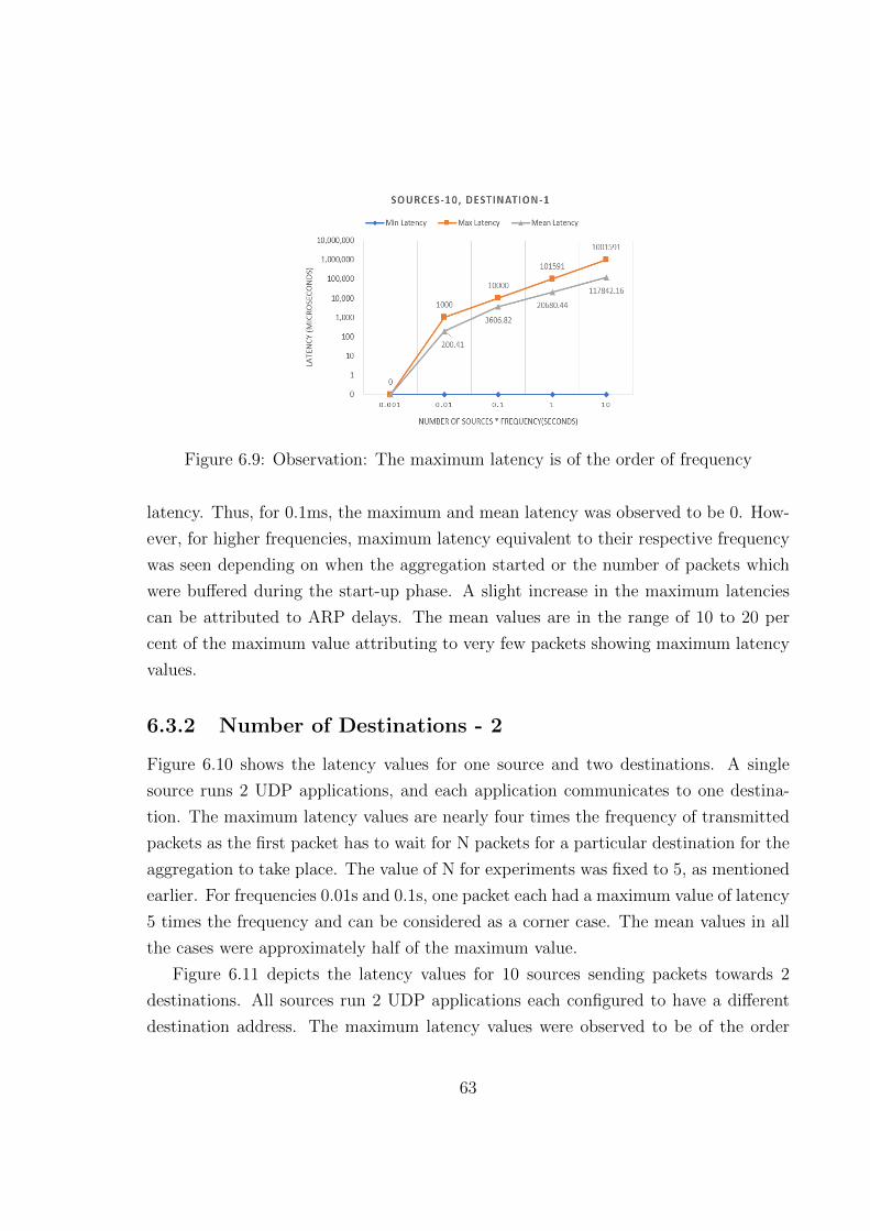
Figure 6.9: Observation: The maximum latency is of the order of frequency
latency. Thus, for 0.1ms, the maximum and mean latency was observed to be 0. How-
ever, for higher frequencies, maximum latency equivalent to their respective frequency
was seen depending on when the aggregation started or the number of packets which
were buffered during the start-up phase. A slight increase in the maximum latencies
can be attributed to ARP delays. The mean values are in the range of 10 to 20 per
cent of the maximum value attributing to very few packets showing maximum latency
values.
6.3.2 Number of Destinations - 2
Figure 6.10 shows the latency values for one source and two destinations. A single
source runs 2 UDP applications, and each application communicates to one destina-
tion. The maximum latency values are nearly four times the frequency of transmitted
packets as the first packet has to wait for N packets for a particular destination for the
aggregation to take place. The value of N for experiments was fixed to 5, as mentioned
earlier. For frequencies 0.01s and 0.1s, one packet each had a maximum value of latency
5 times the frequency and can be considered as a corner case. The mean values in all
the cases were approximately half of the maximum value.
Figure 6.11 depicts the latency values for 10 sources sending packets towards 2
destinations. All sources run 2 UDP applications each configured to have a different
destination address. The maximum latency values were observed to be of the order
63

Figure 6.10: Observation: The maximum latency is (N-1) times the frequency excepttwo cases owing to ARP cache timeout delays
of frequency for frequencies 1ms, 10ms and 100ms. However, for 0.1ms and 1s, the
maximum values were four times(N-1 times) the frequency of packets. These high
values were observed for 10 packets each during the ARP learning process after cache
timeout. The mean latency values are, on the other hand, very low compared to
maximum values.
Figure 6.11: Observation: The maximum latency is of the order of frequency owing toARP delays observed intermittently
64

6.4 Discussion
Graphs 6.12 and 6.13 represent a comparison of Mean latency values for 1 source and
10 sources respectively. For a single source, the mean latency values marginally differ
for both one and two destinations for all values of frequencies.
Figure 6.12: Comparison of Mean Latency(us) for 1 source
Figure 6.13: Comparison of Mean Latency(us) for 10 sources
For ten sources, the mean latency values are higher for two destination network
65

than for a single destination network. This can be attributed to the reason that a
two destination network takes a long time to learn the mac addresses than a single
destination network, owing to no aggregated packets exchanged during that period.
However, this behaviour was not observed to be consistent and is also dependent on
the configured ARP cache timeout values.
The following conclusions are drawn from the test cases for this thesis:
• The percentage of aggregated packets in the access layer is observed to reduce
with an increase in the number of destinations. This is owing to the increasing
time for ARP resolution, during which packets were observed to be transmitted
without aggregation.
• The mean latency values for ten source and two destinations are found to be
higher than ten source one destination, owning to ARP learning times.
66

Chapter 7
Conclusion and Future Works
This chapter lists two use cases where this research can find immediate use in the real
world. Final remarks on this project are then listed in the conclusion section of this
chapter. Lastly, the future works section talks about how this research can be further
extended and tested to benefit the world of IoT.
7.1 Use Cases
This section talks about two different scenarios where this dissertation can help to
reduce the number of packets generated by IoT devices and increase the efficiency of
the network.
7.1.1 Irish Water Meters
Irish Water has installed nearly 755,000 water meters across the country to read water
supply values in Irish households. It measures the volume of water that goes into a home
in cubic meters. These meters support Automatic Meter Reading(AMR) technology
to get the readings and use a drive-by method to record the readings once every three
months. Using this system, a vehicle containing a receiver unit passes by the houses
and records the water meter recordings using wireless methods without opening the
water meter box where the water meters act as the transmitters.
In this use case, readings from 755,000 meters create a large amount of traffic in the
access network. The data generated by meters is a float value, and hence the payload of
67

these packets is minimal, and the overhead of headers is high. These packets are all sent
to the same destination or the Irish Water office. Thus, the packets from the meters
can be sent to an aggregator located at the edge network. This switch can aggregate
the traffic based on the destination which can not only help to reduce the amount of
traffic generated by the access networks but also avoid the drive-by mechanism used
to collect readings in the current scenario.
7.1.2 Applied to TCD’s Campus
This research can also be applied to any college or office campus such as Trinity College
Dublin (TCD), which stores its IoT data on the cloud like Google Cloud or AWS
(Amazon Web Services). Campuses usually deploy many wireless battery powered
sensors which generate data at high frequencies( order of few seconds or minutes).
Due to scale deployments, these sensors would generate large amounts of data. Thus,
an aggregator can be installed at the boundary of the TCD network and the access
network. This access network contains around three to four hops, for example, packets
flow through HEAnet (Irelands National Education and Research Network) and INEX
(Internet Neutral Exchange Association Ltd) to a POP(point of presence) switch where
a deaggregator can be installed. The deaggregated packets can now be routed to the
final destination, which is the cloud.
7.2 Conclusion
This dissertation aimed at integrating support for packet aggregation in OpenFlow
in an IoT network, and analyse its impact on the traffic flowing through the access
network. Through this thesis, we targeted to solve the issue of scale in IoT network
by utilising the principles of software-defined networking with the aggregation of data.
Below is the list of major contributions and benefits of this research:
• Extend OpenFlow to support aggregation of packets based on flows. In our case,
the destination address was used. One of the major goals of this project was to
achieve aggregation of heterogeneous data having small payload values destined
to the same address which was successfully achieved.
68

• Extend OpenFlow switch to perform both aggregation and deaggregation of pack-
ets at the boundary of edge network and access network, to minimise the number
of packets in the access network and increase the lifetime of the network compo-
nents. This step was executed as well.
• Analyse the behaviour of the network traffic in both aggregated and non-aggregated
scenarios and study the trade-offs of implementing aggregation in an IoT network.
For this step, two features: percentage of reduction of traffic in the access network
in aggregated to non-aggregated scenario and latency of packets due to buffering
in the aggregator were studied.
The percentage of packets reduced was as high as 79 per cent for a single desti-
nation system at 1s frequency. This value of polling interval is closest in terms
of granularity to the real world. A marginal reduction in the percentage of ag-
gregated packets was also observed at a higher frequency of packets. Regarding
latency analysis, maximum latency values were observed to be N(aggregation
factor) times the frequency of packets for a single-sourced system whereas it was
of the order of frequency of packets for a 10 sourced system.
7.3 Future Works
As a part of future works, the following enhancements can be made to this research to
gain an in-depth understanding of the behaviour of IoT traffic in access network in an
OpenFlow enabled programmable network which supports aggregation:
• Currently, the aggregator switch performs aggregation based on the length of the
buffered packets in the aggregate buffer or the aggregation factor(N) as commu-
nicated by the controller during the initial setup phase. This functionality of the
aggregator can be extended to incorporate aggregation based on a timer as well,
to avoid delays or packet drops due to an insufficient number of packets.
• As a part of this research, only 73 and 20 test cases were executed to examine the
percentage of packet reduction in the access network and packet latency at the
aggregator, respectively. This only forms a fraction of the number of test cases
identified. Thus, thorough testing of the complete network with all the packet
69

sizes and aggregation factors list in table 6.1 should be performed to get a better
insight into the results.
• In addition to the parameters considered in table 6.1, scaled networks with greater
sources and destination in the order of real-world networks should be tested as
well.
• Networks with multiple OpenFlow controllers and access network containing mul-
tiple network components with different routes to the destination should be tested
for both aggregated and non-aggregated scenarios.
• This project only supports the transmission of data from source to destination.
Thus, it can be further extended to support scenarios for bidirectional and multi-
directional communication.
• In addition to this, the project supports only uniform aggregation mechanism,
and cannot be applied to scenarios which require a real-time transfer of data.
Thus, the extension of this project to support selective aggregation to handle
both real-time and uniform aggregation applications.
70

Bibliography
[1] N. S. Kumar and P. Nirmalkumar, “A novel architecture of smart healthcare sys-
tem on integration of cloud computing and iot,” in 2019 International Conference
on Communication and Signal Processing (ICCSP), pp. 0940–0944, IEEE, 2019.
[2] L. Atzori, A. Iera, and G. Morabito, “The internet of things: A survey,” Computer
networks, vol. 54, no. 15, pp. 2787–2805, 2010.
[3] D. Kreutz, F. Ramos, P. Verissimo, C. E. Rothenberg, S. Azodolmolky, and
S. Uhlig, “Software-defined networking: A comprehensive survey,” arXiv preprint
arXiv:1406.0440, 2014.
[4] N. McKeown, T. Anderson, H. Balakrishnan, G. Parulkar, L. Peterson, J. Rexford,
S. Shenker, and J. Turner, “Openflow: enabling innovation in campus networks,”
ACM SIGCOMM Computer Communication Review, vol. 38, no. 2, pp. 69–74,
2008.
[5] F. Hu, Q. Hao, and K. Bao, “A survey on software-defined network and openflow:
From concept to implementation,” IEEE Communications Surveys & Tutorials,
vol. 16, no. 4, pp. 2181–2206, 2014.
[6] A. Lara, A. Kolasani, and B. Ramamurthy, “Network innovation using openflow:
A survey,” IEEE communications surveys & tutorials, vol. 16, no. 1, pp. 493–512,
2013.
[7] B. Pfaff, B. Lantz, B. Heller, et al., “Openflow switch specification, version 1.3.
0,” Open Networking Foundation, 2012.
71

[8] M. P. Fernandez, “Comparing openflow controller paradigms scalability: Reac-
tive and proactive,” in 2013 IEEE 27th International Conference on Advanced
Information Networking and Applications (AINA), pp. 1009–1016, IEEE, 2013.
[9] P. Bosshart, D. Daly, G. Gibb, M. Izzard, N. McKeown, J. Rexford, C. Schlesinger,
D. Talayco, A. Vahdat, G. Varghese, et al., “P4: Programming protocol-
independent packet processors,” ACM SIGCOMM Computer Communication Re-
view, vol. 44, no. 3, pp. 87–95, 2014.
[10] P. L. Consortium, “P416 language specifications.(2018).” https://p4.org/p4-
spec/docs/P4-16-v1.1.0-spec.html, 2018.
[11] A. Sivaraman, C. Kim, R. Krishnamoorthy, A. Dixit, and M. Budiu, “Dc. p4:
Programming the forwarding plane of a data-center switch,” in Proceedings of the
1st ACM SIGCOMM Symposium on Software Defined Networking Research, p. 2,
ACM, 2015.
[12] L. Jose, L. Yan, G. Varghese, and N. McKeown, “Compiling packet programs to
reconfigurable switches,” in 12th {USENIX} Symposium on Networked Systems
Design and Implementation ({NSDI} 15), pp. 103–115, 2015.
[13] C. Systems, “Cisco SD-WAN Design Guide.”
https://www.cisco.com/c/dam/en/us/td/docs/solutions/CVD/SDWAN/CVD-
SD-WAN-Design-2018OCT.pdf, 2018.
[14] P. L. Consortium, “P4 runtime.” https://s3-us-west-
2.amazonaws.com/p4runtime/docs/v1.0.0/P4Runtime-Spec.html, 2019.
[15] A. Mahmud and R. Rahmani, “Exploitation of openflow in wireless sensor net-
works,” in Proceedings of 2011 International Conference on Computer Science and
Network Technology, vol. 1, pp. 594–600, IEEE, 2011.
[16] T. Luo, H.-P. Tan, and T. Q. Quek, “Sensor openflow: Enabling software-defined
wireless sensor networks,” IEEE Communications letters, vol. 16, no. 11, pp. 1896–
1899, 2012.
72

[17] S. Costanzo, L. Galluccio, G. Morabito, and S. Palazzo, “Software defined wireless
networks (sdwn): Unbridling sdns,” in European workshop on software defined
networking, pp. 1–6, 2012.
[18] Y. Li, X. Su, J. Riekki, T. Kanter, and R. Rahmani, “A sdn-based architecture
for horizontal internet of things services,” in 2016 IEEE International Conference
on Communications (ICC), pp. 1–7, IEEE, 2016.
[19] Y.-B. Lin, S.-Y. Wang, C.-C. Huang, and C.-M. Wu, “The sdn approach for the
aggregation/disaggregation of sensor data,” Sensors, vol. 18, no. 7, p. 2025, 2018.
[20] A. Koike, T. Ohba, and R. Ishibashi, “Iot network architecture using packet aggre-
gation and disaggregation,” in 2016 5th IIAI International Congress on Advanced
Applied Informatics (IIAI-AAI), pp. 1140–1145, IEEE, 2016.
[21] S. Bera, S. Misra, and A. V. Vasilakos, “Software-defined networking for internet of
things: A survey,” IEEE Internet of Things Journal, vol. 4, no. 6, pp. 1994–2008,
2017.
[22] Z. Qin, G. Denker, C. Giannelli, P. Bellavista, and N. Venkatasubramanian, “A
software defined networking architecture for the internet-of-things,” in 2014 IEEE
network operations and management symposium (NOMS), pp. 1–9, IEEE, 2014.
[23] N. S. Patil and P. Patil, “Data aggregation in wireless sensor network,” in IEEE
international conference on computational intelligence and computing research,
pp. 28–29, 2010.
[24] T.-Y. Chao, K. Wang, L. Wang, and C.-W. Lee, “In-switch dynamic flow aggre-
gation in software defined networks,” in 2017 IEEE International Conference on
Communications (ICC), pp. 1–6, IEEE, 2017.
[25] S. Das, Y. Yiakoumis, G. Parulkar, N. McKeown, P. Singh, D. Getachew, and
P. D. Desai, “Application-aware aggregation and traffic engineering in a converged
packet-circuit network,” in National Fiber Optic Engineers Conference, p. NThD3,
Optical Society of America, 2011.
73

[26] S. Song, L. Ling, and C. Manikopoulo, “Flow-based statistical aggregation schemes
for network anomaly detection,” in 2006 IEEE International Conference on Net-
working, Sensing and Control, pp. 786–791, IEEE, 2006.
[27] E. Mlaih and S. A. Aly, “Secure hop-by-hop aggregation of end-to-end concealed
data in wireless sensor networks,” in IEEE INFOCOM Workshops 2008, pp. 1–6,
IEEE, 2008.
[28] E. Fitzgerald, M. Pioro, and A. Tomaszewski, “Energy-optimal data aggregation
and dissemination for the internet of things,” IEEE Internet of Things Journal,
vol. 5, no. 2, pp. 955–969, 2018.
[29] I. Stojmenovic, “Machine-to-machine communications with in-network data ag-
gregation, processing, and actuation for large-scale cyber-physical systems,” IEEE
Internet of Things Journal, vol. 1, no. 2, pp. 122–128, 2014.
[30] E. Fasolo, M. Rossi, J. Widmer, and M. Zorzi, “In-network aggregation techniques
for wireless sensor networks: a survey,” IEEE Wireless Communications, vol. 14,
no. 2, pp. 70–87, 2007.
[31] J. Xu, G. Yang, Z.-y. Chen, L. Chen, and Z. Yang, “Performance analysis of
data aggregation algorithms in wireless sensor networks,” in 2011 International
Conference on Electrical and Control Engineering, pp. 4619–4622, IEEE, 2011.
[32] R. Hornig, “OpenFlow model for OMNeT++ 5.4 and INET 3.6.”
https://github.com/inet-framework/openflow, 2016.
[33] T. R. Henderson, M. Lacage, G. F. Riley, C. Dowell, and J. Kopena, “Network
simulations with the ns-3 simulator,” SIGCOMM demonstration, vol. 14, no. 14,
p. 527, 2008.
[34] P. Pupatwibul, A. Banjar, A. Al Sabbagh, and R. Braun, “A comparative review:
Accurate openflow simulation tools for prototyping.,” JNW, vol. 10, no. 5, pp. 322–
327, 2015.
74

Appendix
Figure 1: List of Abbreviations
75