openvision™ dx
TRANSCRIPT

OP
ER
AT
ING
MA
NU
AL.
MA
N-0
59, R
EV
ISIO
N A
OPENVISION™ DX.OVDX-NDT-70 HARDWARE MANUAL

Page 2 of 29 QSA Global, Inc. 40 North Avenue Burlington, MA 01803 888.272.2242 781.272.2000 F: 781.359.9179 qsa-global.com
TABLE OF CONTENTS. Table of Contents. ................................................................................................................................................................... 2
Introduction. ............................................................................................................................................................................. 3
SYSTEM Specifications. ......................................................................................................................................................... 3
Safety Precautions .................................................................................................................................................................. 5
Operating Conditions ........................................................................................................................................................... 6
Training ................................................................................................................................................................................ 6
Precautions .......................................................................................................................................................................... 6
getting to know your OpenVision™ Digital X-Ray (OVDX) System. ....................................................................................... 7
System Overview ................................................................................................................................................................. 7
OVDX Main Housing Details ............................................................................................................................................... 8
Principles of Operation ............................................................................................................................................................ 9
Radiographic Quality ........................................................................................................................................................... 9
Sources (X-Ray & Gamma Ray) ......................................................................................................................................... 9
Simplified Exposure Determination with X-Rays ................................................................................................................. 9
Radiation Zones .................................................................................................................................................................... 10
Output Radiation Levels .................................................................................................................................................... 10
Backscatter Radiation Levels ............................................................................................................................................ 11
Backscatter ........................................................................................................................................................................ 12
Operation. .............................................................................................................................................................................. 14
Quick Setup / Scanning ..................................................................................................................................................... 14
Accessories. .......................................................................................................................................................................... 17
Heads Up Display (HUD) ................................................................................................................................................... 17
Handle Extension Assembly .............................................................................................................................................. 20
Installation of Handle Extension Assembly .................................................................................................................... 21
Monitor ............................................................................................................................................................................... 23
Imager Shield .................................................................................................................................................................... 25
Maintenance. ......................................................................................................................................................................... 26
Troubleshooting. ................................................................................................................................................................... 27
QSA Global, Inc. Contact Information ............................................................................................................................... 28
Appendix 1: Parts List. .......................................................................................................................................................... 29

Page 3 of 29
QSA Global Inc. 40 North Avenue Burlington, MA 01803 888.272.2242 781.272.2000 F: 781.359.9179 qsa-global.com
INTRODUCTION. The OVDX-70-NDT is the world’s only hand-held live video X-Ray system specifically designed for corrosion under insulation inspection. With patent pending ergonomic features and improved weight distribution, crews can quickly set up and begin scanning. Transfer files simply from OVDX via USB memory stick for review and inclusion in inspection reports.
SYSTEM SPECIFICATIONS. Table 1 OVDX Specifications
Imaging Area (Field of View) 4 in. x 6 in. (10 cm x 15 cm)
Dimensions X-Ray Tube to Imager Clearance Throat depth Imager Thickness X-Ray Tube Thickness
9.5 in. (24 cm) to 20.9 in. (53 cm) 21 in. (58 cm) 2.5 in. (6.4 cm) 3.4 in. (8.7 cm)
Startup Time (est.) 30 seconds
Shutdown Time (est.) 5 seconds
X-Ray Energies Low Medium High
Voltage (kV)
40 55 70
Current (mA)
0.300 0.218 0.171
Dose @ 12 in (30.5 cm) from X-Ray Tube 50 R/hr (0.5 Sv/hr) 80 R/hr (0.8 Sv/hr) 95 R/hr (0.95 Sv/hr)
Beam Collimation (Approximate) 25° Horizontal 17° Vertical
Image Resolution 0.004 in. (0.1 mm)
Battery Life Continuous duty with 5 AH battery Standby
3 hours 8 hours
System Weight C-Arm Monitor w/ Handle (optional) Packaged System (shipping weight)
11 lbs. (5 kg) 6.4 lbs. (2.9 kg) 53 lbs. (24 kg)
Operating Temperature -20° F to 120° F (-29° C to 49° C)
Storage Temperature -30° F to 140° F (-34.5° C to 60° C)
Display Options 10 in. LED Monitor: 1024 x 600 pixels PirateEye: 854 x 480 pixels Any device that accepts HDMI signals
Recording Internal Storage Capacity Resolution (Image and Video) Image / Video Transfer Method
128 GB 1280 X 720 USB
Shipping Dimensions 32 in. x 20.5 in. x 12.5 in (82 cm x 52 cm x 32 cm)
FDA Accession # 1680071-000

Page 4 of 29 QSA Global, Inc. 40 North Avenue Burlington, MA 01803 888.272.2242 781.272.2000 F: 781.359.9179 qsa-global.com
The OVDX-70-NDT is built in compliance with ISO 9001:2015 and meets the following standards when used as directed:
ANSI/HPS N43.5 (2005) Ionizing Radiation Regulations (2017) ISTA 3A Over the Road vibration standard MIL-STD-810, Method 514, Annex C, Cat 4 REACH/ROHS
HMD
ANSI Z87.1+, US Federal OSHA US Mil Spec MIL-PRF-31013 CE END 166 FTKN
Battery/Charger
California Energy Commission
Underwriters Laboratory for Canada and U.S.
Page 5 of 29
QSA Global Inc. 40 North Avenue Burlington, MA 01803 888.272.2242 781.272.2000 F: 781.359.9179 qsa-global.com
SAFETY PRECAUTIONS. WARNING
Do not perform any unauthorized modifications to the OpenVision™ system or its components.
It is important that trained and qualified personnel perform or supervise a daily safety inspection of the OpenVision™ system for any defects. Do not compromise on safety. Always perform daily system inspections prior to use. Any foreign material (dirt, mud, ice, etc.) must be removed before using the system. Inspect, clean, and test the equipment as described in this manual to ensure long-term safety and reliability. Do not use any component that is not approved for use with the OpenVision™ system or any after-market component. Doing so may compromise the safety features designed into the system. Defective equipment that is discovered during daily inspections must be removed from service until repaired or replaced.
Equipment operators must follow all operating instructions, in the order shown, to ensure safe operations and compliance with government regulations.
Personnel operating this equipment must be completely familiar with this manual and they must read and understand these important safety alerts before proceeding:
IMPORTANT SAFETY ALERTS NOTICE: Can cause minor problems and reminders.
CAUTION: Can cause equipment damage or potential problems.
WARNING: Can cause serious or fatal injury.
WARNING: JOB SITE SAFETY PRECAUTIONSSurveillance Only trained and qualified individuals, or assistants working under their direct supervision, may operate the OpenVision™ DX system. The qualified individuals must be physically present at the site and able to control and limit access to the vicinity of the work.
Locking Keep the OpenVision™ controller locked while assembling the system and when not being used to perform scanning. Locked is defined as the controller key switch in the Off position with the key removed. Store the key in a secure location.

Page 6 of 29 QSA Global, Inc. 40 North Avenue Burlington, MA 01803 888.272.2242 781.272.2000 F: 781.359.9179 qsa-global.com
Operating Conditions OpenVision™ DX is designed for applications where the system will not be exposed to harsh handling or environmental extremes. See System Specifications for more information.
Training It is required that OpenVision™ DX operators are properly trained and qualified to perform radiographic inspections. This manual does not address radiographic inspection techniques or procedures.
Precautions The OpenVision™ DX system is designed for portability and is ruggedized for industrial environments. However, it does contain fragile components. Use care to avoid strong vibrations and shock conditions (e.g. equipment drops or transportation outside the approved case) to the main housing, imager housing, and display(s).
CAUTION Do not attempt to open or modify the imager housing, main housing, or X-ray tube. Opening any of these components will void the system warranty and may expose the operator to a high voltage shock hazard.
CAUTION Do not allow liquids to come into contact with any part of the OpenVision™ DX system. The main and imager housings have been made water resistant, but they are not “Water Proof”. Appropriate care should be taken to protect all cabling and connectors to ensure reliable and safe operation of the OpenVision™ DX system.
WARNING: CLASS 2 TARGET LASER
Because the blink reflex (glare aversion response to bright lights) will limit the exposure to no more than 0.25 seconds, Class 2 laser pointers are considered to be safe. Furthermore, Class 2 lasers do not harm eyes unless a person deliberately stares into the beam, making laser protective eyewear not necessary. A Class 2 laser is not a skin or materials burn hazard. NEVER aim any laser towards an aircraft or vehicle in motion.
Page 7 of 29
QSA Global Inc. 40 North Avenue Burlington, MA 01803 888.272.2242 781.272.2000 F: 781.359.9179 qsa-global.com
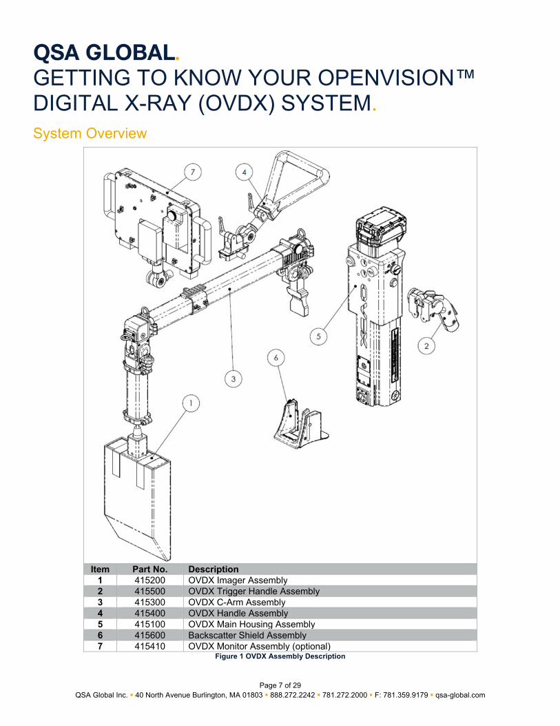
GETTING TO KNOW YOUR OPENVISION™ DIGITAL X-RAY (OVDX) SYSTEM. System Overview
Figure 1 OVDX Assembly Description
Item Part No. Description1 415200 OVDX Imager Assembly2 415500 OVDX Trigger Handle Assembly3 415300 OVDX C-Arm Assembly4 415400 OVDX Handle Assembly5 415100 OVDX Main Housing Assembly6 415600 Backscatter Shield Assembly7 415410 OVDX Monitor Assembly (optional)

Page 8 of 29 QSA Global, Inc. 40 North Avenue Burlington, MA 01803 888.272.2242 781.272.2000 F: 781.359.9179 qsa-global.com
OVDX Main Housing Details
Item Part No. Description1 ELE054 Milwaukee® M18™ Battery2 --- CPU Power Indicator3 --- USB Connection4 313056 Controller Key5 --- HDMI Connection 16 --- System Status Indicator7 --- Targeting Camera8 --- Targeting Laser9 --- X-Ray Port10 --- Audio Speaker11 415500 Trigger Handle Assembly12 415130 Trigger Adapter Port Cover13 --- Strain Relief for HDMI Connection 2
Figure 2 OVDX Main Housing Assembly (Item # 415100)

Page 9 of 29
QSA Global Inc. 40 North Avenue Burlington, MA 01803 888.272.2242 781.272.2000 F: 781.359.9179 qsa-global.com
PRINCIPLES OF OPERATION. Radiography uses X-rays or gamma rays passing through a specimen onto an imaging medium (film, digital imager, imaging plate, etc.) on the opposite side. The quality and quantity of radiation reaching the imaging medium is largely determined by the object’s thickness and density. Radiation energy (X-Ray = kV; Gamma Ray = isotope) governs its penetrating power. Radiation intensity is governed by current (milliampere or mA) for X-rays, and by content activity (Curie/Becquerel) for radioisotopes.
Radiographic Quality Radiographic quality depends on an image’s photographic (density, contrast) and geometric (definition, distortion) properties. Proper energy and intensity selection are both essential for producing high-quality radiographs.
Sources (X-Ray & Gamma Ray) Radiation
Source Energy (Quality)
Intensity (Quantity)
X-Ray
Determined by voltage (kV) Higher kV = shorter wavelength = higher penetration
Determined by tube current (mA) Higher mA = more electrons = more X-rays
Gamma Ray
Determined by type of radioisotope (keV or MeV)
Determined by radioactivity (Ci/Bq): Gamma Rays produced by unstable nuclei disintegrations
Higher isotope energy = increasing penetrating capability: Co-60 > Cs-137 > Ir-192 > Se-75
Higher Ci = more disintegrations of nuclei = more gamma rays
Table 2 Radiation Comparisons
Simplified Exposure Determination with X-Rays By using X-rays, the OpenVision™ DX system has the advantage of real-time radiography (immediate availability of images). Time calculations (as used in gamma-ray radiography exposure) are not needed for X-ray radiography.
To determine exposure requirements, start on the lowest kV/mA settings and adjust to achieve the desired image quality.

Page 10 of 29 QSA Global, Inc. 40 North Avenue Burlington, MA 01803 888.272.2242 781.272.2000 F: 781.359.9179 qsa-global.com
RADIATION ZONES. Output Radiation Levels OVDX radiation levels vary depending on kV/mA settings. QSA performs testing at maximum power (70 kV, 0.17 mA) to verify collimation and image quality. Operators must be aware of safe boundary distances while using the OVDX. When the main housing is fully expanded (“D” = 53cm [20.8in]), the most susceptible area of high dose rate (when specimens do not block entire X-ray output beam) is immediately adjacent to imager housing. The “C” callout in Figure 3 is positioned in this approximate area.
Figure 3 OVDX Output Boundary Distances
Figure 3 shows boundary distances for 2, 0.75 and 0.25mR/hr. Table 3 below details typical distances for these boundary levels with different operating conditions.
NOTICE: The imager shield (see Figure 25 on page 25, item #415230, not shown in Figure 3) provides shielding to either side of the imager when the specimen being imaged (e.g. small piping) does not completely attenuate the X-ray output.
Main Housing Distance to Imager (in [cm])
“D” kV / mA
Imager Shield?
Boundary Distance (ft [m])2mR/hr
(20Sv/hr) “A”
0.75mR/hr (7.5Sv/hr)
“B”
0.25mR/hr (2.5Sv/hr)
“C”
20.8 [53] (Fully Expanded) 70 / .17 No 82 [24.9] 134 [40.7] 231 [70.5]
20.8 [53] (Fully Expanded) 70 / .17 Yes 10.4 [3.2] 17.4 [5.3] 30 [9.2]
13.8 [35cm] 70 / .17 No 17.4 [5.3] 28.2 [8.6] 49 [15]
13.8 [35cm] 70 / .17 Yes 9.8 [3.0] 16.1 [4.9] 27 [8.5] Table 3 Boundary Distance Comparison
Actual measurements can vary based on the material being scanned and its geometry. To minimize operator exposure, QSA recommends using a backscatter shield assembly (Item # 415600) with your OVDX.
Main Housing Imager

Page 11 of 29
QSA Global Inc. 40 North Avenue Burlington, MA 01803 888.272.2242 781.272.2000 F: 781.359.9179 qsa-global.com
Backscatter Radiation Levels
Survey Point
Without Backscatter Shield mR/Hr (µSv/hr)
With Backscatter Shield in mR/Hr (µSv/hr)
A 2.5 (25) 1(10) B 7(70) 5(50) C 5.5 (55) 1.5 (15) D 1 (10) 0 (0) E 6 (60) 1.5 (15) F 6.5 (65) 5 (50) G ≤Background (BKGD) ≤BKGD H ≤BKGD ≤BKGD I ≤BKGD ≤BKGD J ≤BKGD ≤BKGD K ≤BKGD ≤BKGD
Figure 4 Example Scatter Radiation Survey
Figure 4 shows an example survey of backscatter radiation (user exposure) for a typical sample (NOTICE: for reference only; actual readings may vary). The example survey shown in Figure 4 was created with the following conditions:
8" Steel Pipe 2" Calcium Silicate Insulation .040” [1 mm] thick Aluminum Cladding 70 kV @ 0.17 mA (maximum power)
See the following section for additional information on backscatter.

Page 12 of 29 QSA Global, Inc. 40 North Avenue Burlington, MA 01803 888.272.2242 781.272.2000 F: 781.359.9179 qsa-global.com
Backscatter
CAUTION Whenever scanning an unknown material and/or geometry, it is recommended that operators monitor for backscatter levels to minimize operator dose.
Backscatter occurs when X-rays interact with material (piping, insulation, etc.), potentially travelling in undesirable directions (e.g. towards the operator). Backscatter is dependent on many variables including geometry, material, and energy level. It can potentially increase the dose to the operator’s extremities.
The best way to minimize backscatter is to use the lowest kV / mA combination to achieve acceptable images. Use of the backscatter shield (Figure 5) will help reduce the amount of backscatter when firmly applied to the scanning surface as shown in Figure 7.
Figure 5 Backscatter Shield (Item # 415600)

Page 13 of 29
QSA Global Inc. 40 North Avenue Burlington, MA 01803 888.272.2242 781.272.2000 F: 781.359.9179 qsa-global.com
Figure 6 Example of Backscatter
Figure 7 OVDX with backscatter shield properly positioned against insulation sheathing.

Page 14 of 29 QSA Global, Inc. 40 North Avenue Burlington, MA 01803 888.272.2242 781.272.2000 F: 781.359.9179 qsa-global.com
OPERATION.
Quick Setup / Scanning Your OVDX system can be setup and ready for scanning in a matter of seconds by following these steps:
Unlock main housing by pressing red circular release button and unfold to operating position:
Figure 8 Unlock Main Housing
WARNING
When the System Status Indicators turn AMBER (see Figure 2), ionizing radiation is being produced. If you wish to perform extended operations with the DX system, ensure that ambient temperatures are below 125 °F (52 °C).
Red Button
Operating Position

Page 15 of 29
QSA Global Inc. 40 North Avenue Burlington, MA 01803 888.272.2242 781.272.2000 F: 781.359.9179 qsa-global.com
Repeat action for imager housing:
Figure 9 Unlock Imager Housing
Install Backscatter shield by lining up grooves and slide/lock into position shown, and position handles as desired:
Figure 10 Backscatter shield installed, available handle adjustments
Red Button
Monitor Mount (Optional)
Backscatter Shield

Page 16 of 29 QSA Global, Inc. 40 North Avenue Burlington, MA 01803 888.272.2242 781.272.2000 F: 781.359.9179 qsa-global.com
Install controller key and turn to ON and allow time for system to initialize. System status indicators (located on either side of main housing) will turn GREEN when system is ready.
Figure 11 Indicators and Power Switch Details
Verify kV/mA settings on main status screen. Perform test shot to verify X-ray functionality.
Controller Key (ON)
System Status Indicator
CPU Power Indicator

Page 17 of 29
QSA Global Inc. 40 North Avenue Burlington, MA 01803 888.272.2242 781.272.2000 F: 781.359.9179 qsa-global.com
ACCESSORIES.
Heads Up Display (HUD) This accessory (Item #415140) allows for an alternative to a display mounted directly to the DX system. HUD specifications:
Ballistic Protection Standards:
U.S. MIL SPEC MIL-PRF-31013 ANSI Z87.1+ U.S. Federal OSHA CE EN 166 FTKN
Temperature:
Storage: -4°F to 140°F (-20C – 60C) Operating: 32°F to 122°F (0C-50C)
Weight
114g
The display position can be moved in multiple directions based on user preferences:
Figure 12 Available directional adjustments to display

Page 18 of 29 QSA Global, Inc. 40 North Avenue Burlington, MA 01803 888.272.2242 781.272.2000 F: 781.359.9179 qsa-global.com
To make slight adjustments to the focus, adjust the diopter to the left or right using your index finger.
The standard configuration provides the image to your right eye. Clear or tinted lenses can be used based on external lighting conditions:
Figure 13 Diopter adjustment
Figure 14 Example image output for HUD

Page 19 of 29
QSA Global Inc. 40 North Avenue Burlington, MA 01803 888.272.2242 781.272.2000 F: 781.359.9179 qsa-global.com
1 Micro-USB charging port *
2 Video input
3 Output to heads-up-display
4 HDMI input
5 Power
6 Reduce brightness
7 Increase brightness
8 Toggle aspect ratio (4:3 / 16:9) **
9 Toggle color / black and white
*
The HUD controller must be charged separately with a USB charger. It is not powered by the OVDX system. Expected battery life is 10 hours.
** 4:3 aspect ratio is recommended
Figure 15 HUD controller and power supply
6
8
9
2
7
4
5
1 3

Page 20 of 29 QSA Global, Inc. 40 North Avenue Burlington, MA 01803 888.272.2242 781.272.2000 F: 781.359.9179 qsa-global.com
Handle Extension Assembly The trigger assembly (Item # 415500) can be relocated to the top of the C-Arm by using the handle extension assembly (Item # 415510). Installation aids in inspection where the OVDX is utilized in unusual orientations or tight locations.
Figure 17 OVDX with handle extension assembly installed on top of C-Arm.
Figure 16 Handle extension assembly (Item # 415510, split rail slider not shown)
Page 21 of 29
QSA Global Inc. 40 North Avenue Burlington, MA 01803 888.272.2242 781.272.2000 F: 781.359.9179 qsa-global.com
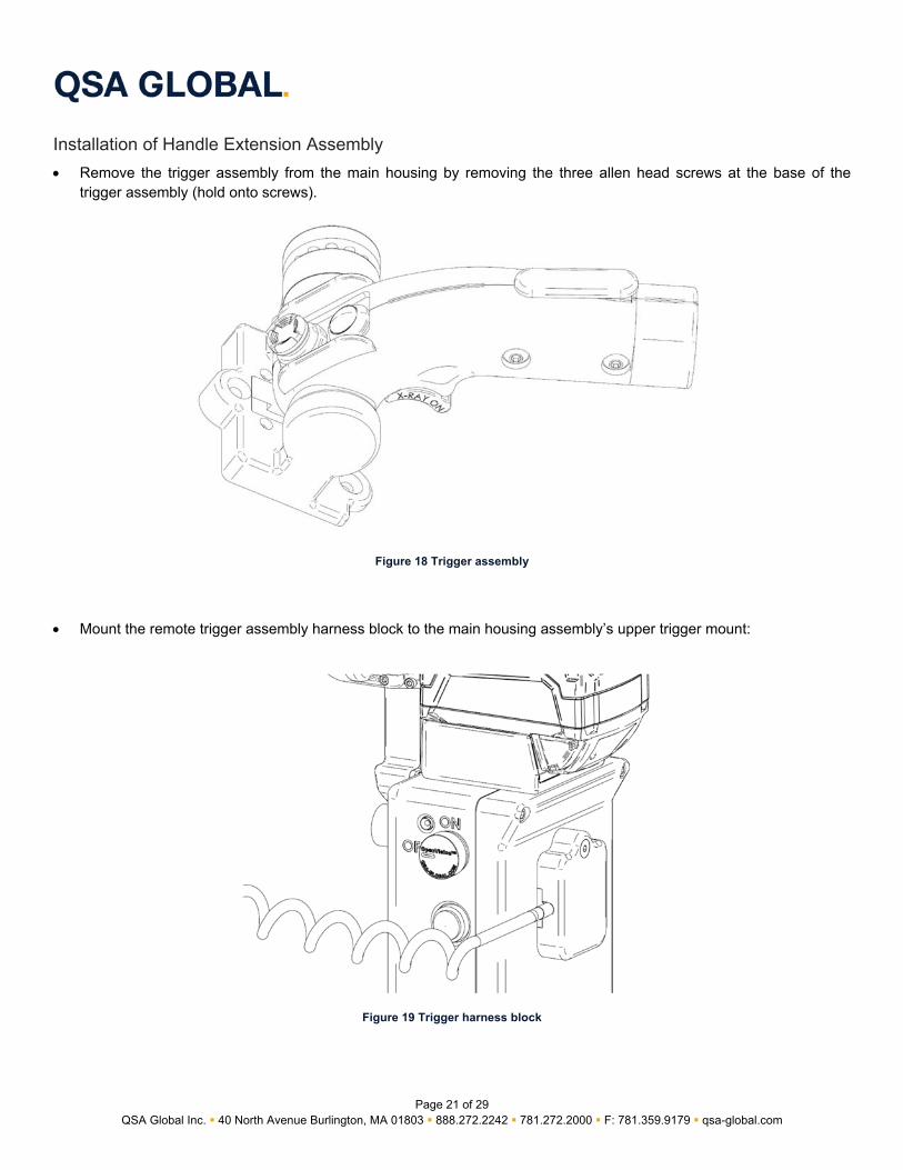
Installation of Handle Extension Assembly
Remove the trigger assembly from the main housing by removing the three allen head screws at the base of the trigger assembly (hold onto screws).
Figure 18 Trigger assembly
Mount the remote trigger assembly harness block to the main housing assembly’s upper trigger mount:
Figure 19 Trigger harness block

Page 22 of 29 QSA Global, Inc. 40 North Avenue Burlington, MA 01803 888.272.2242 781.272.2000 F: 781.359.9179 qsa-global.com
Mount the split rail slider onto the C-Arm, then attach the remote trigger mounting block onto slider:
Figure 20 Handle Extension Mounting Block Attached
Attach the trigger assembly to the extension mounting block using three allen head screws from before:
Figure 21 Trigger Attached Mounting Block
Allen Head Screws
Split Rail Slider
Handle Extension Mounting Block

Page 23 of 29
QSA Global Inc. 40 North Avenue Burlington, MA 01803 888.272.2242 781.272.2000 F: 781.359.9179 qsa-global.com
Monitor The monitor assembly (Item # 415410) is an optional accessory which mounts to the OVDX handle assembly (Item #415400) by the mounting post (Figure 22, Item #1).
1 Mounting Post2 Power/Charging Indicator
Figure 22 Monitor - Front View.
The OVDX monitor is powered by both an external and internal battery. The external battery charger (Figure 24) can charge two batteries. The internal battery is charged with either a 12-volt DC charger connected to the power input jack (Figure 23, Item #5), or with the external battery (as shown in Figure 23). Charging indicator will turn RED while charging (Figure 22, Item #2), and GREEN when monitor is on.
NOTICE The monitor’s DVR functionality is not compatible with the DX system. Image/video recording is handled directly within the DX system software.
2
1

Page 24 of 29 QSA Global, Inc. 40 North Avenue Burlington, MA 01803 888.272.2242 781.272.2000 F: 781.359.9179 qsa-global.com
3 External Battery4 HDMI Strain Relief5 Power Input Jack6 Power Switch
Figure 23 Monitor - Rear View
Figure 24 Monitor’s External Battery Charger
4
5
6
3

Page 25 of 29
QSA Global Inc. 40 North Avenue Burlington, MA 01803 888.272.2242 781.272.2000 F: 781.359.9179 qsa-global.com
Imager Shield The imager shield (Item # 415230) is an optional accessory which mounts to the OVDX imager assembly in place of the standard imager cover (Item #415200-11).
Figure 25 Imager shield installed (left), and imager cover (right, for reference)
The imager shield is most useful when imaging small pipe or other specimens that do not cover the excess beam on either side of the imager assembly and when the DX system is fully extended. Figure 3 shows the worst-case effect of output radiation levels with and without the imager shield.
Page 26 of 29 QSA Global, Inc. 40 North Avenue Burlington, MA 01803 888.272.2242 781.272.2000 F: 781.359.9179 qsa-global.com
MAINTENANCE. The OVDX has been designed to require minimal maintenance by the operator; daily, visual inspections are necessary. Additionally, specific attention should be paid to the following:
M18™ battery and its mount (on top of Main Housing) – Ensure both are clean, and in sound shape. HDMI cable – Inspect for any cracks or wear. Allen/thumb screws – Check for tightness. Imager bag – Check for excessive wear.
Use a soft, damp cloth to clean to remove dirt and grime from the OVDX.
CAUTION Do not use solvents or apply cleaning agents directly on the OVDX as this can damage the components and/or corrode the electronics.

Page 27 of 29
QSA Global Inc. 40 North Avenue Burlington, MA 01803 888.272.2242 781.272.2000 F: 781.359.9179 qsa-global.com
TROUBLESHOOTING. CAUTION
Opening the OVDX can damage the system and will void any warranty. If faced with any issues regarding the OVDX, contact your QSA Global, Inc. representative immediately for guidance.
The OVDX has been designed as a rugged, safe, reliable system. A series of interlocks and self-checks are built into the system to ensure safe operation. These checks may trigger an error code which will prevent normal operation of the OVDX. Use Table 4 as a reference guide for system error codes.
NOTICE: Prior to any troubleshooting, please ensure that a fully-charged M18™ battery is installed. A low battery may cause system to report false error codes.
Error Code Description Corrective Action
1 Memory Failure Hard drive and/or system memory error or failure. If restart does not clear error, contact your QSA Global, Inc. representative for repair options.
2 LED Failure Status Indicator LED(s) are not functioning properly. If restart does not clear error, contact your QSA Global, Inc. representative for repair options.
3 X-Ray Tube Failure X-Ray tube is not communicating or has malfunctioned. If restart does not clear error, contact your QSA Global, Inc. representative for repair options.
4 X-Ray Over Temperature
X-Ray tube has exceeded its operating temperature, forcing system to stop emitting X-Rays. Perform following actions to recover from this error:
Turn off unit Place in cooler environment for 30 minutes Turn unit on
5 Board Over Temperature
Main control board has overheated. Perform following actions to recover from this error:
Turn Off unit Place in cooler environment for 30 minutes Turn unit on
6 Imaging Camera Failure
Communication error and/or failure with targeting camera. If a restart does not clear error, the USB connection may have loosened. Remove imaging housing from Carbon Fiber Tube and check USB connection to housing and restart. If this does not correct the error, Contact your QSA Global, Inc. representative for repair options.
7 Targeting Camera Failure Communication error and/or failure with targeting camera. Contact your QSA Global, Inc. representative for repair options.
8 Low Voltage M18™ battery has insufficient charge; change battery. Table 4 Error Codes

Page 28 of 29 QSA Global, Inc. 40 North Avenue Burlington, MA 01803 888.272.2242 781.272.2000 F: 781.359.9179 qsa-global.com
QSA Global, Inc. Contact Information Sales/Customer Service
6765 Langley Drive
Baton Rouge, LA 70809 USA
Telephone +1 225 751 5893
Toll Free +1 800 225 1383
Fax +1 225 756 0365
Manufacturing / International Service Center
40 North Avenue
Burlington, MA 01803 USA
Telephone +1 781 272 2000
Toll Free +1 800 815 1383
Fax +1 781 359 9179
North America Service Center
3200 Awesome Lane
LaPorte, TX 77571
Telephone +1 713 944 3200
Fax +1 281 476 9309
All goods and services are sold subject to the terms and conditions of QSA Global, Inc. A copy of these terms and conditions is available upon request.
OpenVision™ is a trademark of QSA Global, Inc.
All brand names and product names where used are acknowledged to be trademarks of their respective holders.
©2019 QSA Global, Inc.

Page 29 of 29
QSA Global Inc. 40 North Avenue Burlington, MA 01803 888.272.2242 781.272.2000 F: 781.359.9179 qsa-global.com
APPENDIX 1: PARTS LIST.
Part # Description
OVDX-NDT-70 OpenVision™ DX System, Complete
415400 OVDX Handle Assembly
415410 OVDX Monitor Assembly
415500 OVDX Trigger Handle Assembly
415600 OVDX Backscatter Shield Assembly
ELE088 HDMI Cable
ELE054 Milwaukee® M18™ Battery
313056 Controller Key
415140 Pirate Eye Head Mount Display
415510 Handle Extension Assembly
415230 Imager Shield Assembly
OpenVision™ is a registered trademark of QSA Global, Inc. Milwaukee® and M18™ are registered trademarks or trademarks of Milwaukee Tool. All product and company names are trademarks™ or registered trademarks® of their respective holders. Use of them does not imply any affiliation with or endorsement of or by them.