opera rhbd multi-core - nasa · opera rhbd multi-core agenda opera program history...
TRANSCRIPT

OPERA RHBD Multi-coreMichael Malone
Draper Laboratory
MAPLDMAPLD 20092009MAPLD MAPLD –– 20092009
31 August 200931 August 2009
1

OPERA RHBD Multi-core Agenda
OPERA Program History Multi-core Motivation Multi-core Motivation
– Why Multi-core For Space The OPERA Hardware and Software
– The Maestro chip– Opera Software Architecture
Radiation Hardening By Design OverviewRadiation Hardening By Design Overview– Single tile radiation performance
Roadmaps and Summary
2

OPERA Definitions OPERA Program
– The On-board Processing Expandable Reconfigurable Architecture (OPERA) Program RHBD Program
DTRA / DARPA’s Radiation Hardened By Design (RHBD) II Program– DTRA / DARPA s Radiation Hardened By Design (RHBD) II Program OPERA Single Core (or Tile) – Product Demonstration Vehicle (PDV) #1
– Single RHBD core with test wrapper– RHBD Program Product Demonstration Vehicle #1 (PDV1)
I t t d T t Chi (ITC) Integrated Test Chip (ITC)– First pass Maestro device testing scheduled to be complete March, 2010
• It becomes Maestro should no errors exist Maestro – The RHBD 49 core processor
Maestro is the radiation hardened by design 49 core general purpose processor based– Maestro is the radiation hardened by design 49 core general purpose processor based on the Tilera TILE64TM
– TRL 6 devices scheduled to be available December, 2010 MDE – Tilera’s Multi-core Development Environment (MDE) for the Tile64TM
OSA OPERA Software Architecture OSA – OPERA Software Architecture ODE – OPERA Development Environment Core or Tile – Single processor within the Maestro device SHIM – Interfaces between the core array and chip I/Os
CHREC CHREC – National Science Foundation’s Center for High-Performance Reconfigurable Computing
(CHREC)• University centers include Florida, George Washington, BYU, and Virginia Tech 3

OPERA Program History
DARPAPCAProgram
MIT PCAConceptArticle
MITRAWProcessor
IBMCellProcessor
GraphicProcessingUnits
ProgramArticleRaytheonMonarchProcessor
?Univ. ofTexas -TRIPS
1999 - 2006
? GovernmentIndependentArchitectureAnalysis - 2006
TileraTLR26480Processor
2nd GenerationRAW Device,IP Procurement6/2007
90 nmRHBD
DesignFiles
DARPA / DTRA RHBD 2 Program
LibrariesFiles
Single
OPERASoftware
Next -Generation
ITC3/2010
4
ProgramRHBDCore4/2008 Maestro
12/2010
GenerationSpaceComputerBoard

OPERA Acquisition Model
Leverage existing microprocessor and software advances– Program origins: DARPA Polymorphic Computer Architecture
(PCA) Program(PCA) Program– Purchase the Tilera Corporation’s Intellectual Property (IP) for
Government spaced-based applicationsUtilize DARPA / DTRA Radiation Hardened By Design (RHBD)– Utilize DARPA / DTRA Radiation Hardened By Design (RHBD) program libraries
• Hardened 90 nm IBM 9SF CMOS design libraries– License existing 3rd party silicon designs– License existing 3 party silicon designs
• Floating point unit, serial – deserializer, phase locked loop, memory interfaces
– Participate in the NSF’s Center for High-Performance a t c pate t e S s Ce te o g e o a ceReconfigurable Computing (CHREC) software consortium
Provide OPERA hardware IP and software free to contractors involved with US space-based applicationscontractors involved with US space based applications
5

Multi-core’s Advantage
Multi-core’s advantage– Improved performance per watt for most applications
Low latency connections between processors– Low latency connections between processors– Parallel processing capability– Commercial industry support
Processor Processor Processor Processor
Traditional Multiprocessor100 l 100 l1000 l
Processor Processor Processor Processor
DRAM~100 cycles
DRAM~100 cycles~1000 cycles
•0 •1 •2 •3 •4 •5 •6 •7
•8 •9 •10 •11 •12 •13 •14 •15
•16 •17 •18 •19 •20 •21 •22 •23
•24 •25 •26 •27 •28 •29 •30 •31
•32 •33 •34 •35 •36 •37 •38 •39
On-chip interface:<10 cyclelatency between processors
Multi-Core Architecture
Multi-core architecture has •40 •41 •42 •43 •44 •45 •46 •47
•48 •49 •50 •51 •52 •53 •54 •55
•56 •57 •58 •59 •60 •61 •62 •63
processorsinherently faster processor communication
6

Why Multi-core for Space?
S i h ll
OPERA’s Goal - Revolutionary Improvement in Processor Capabilities for Space Applications
Space processing challenges– Advancing mission requirements– Shrinking decision timelines– Providing a common high-performance hardware and softwareProviding a common high-performance hardware and software
technology foundation OPERA is the Government’s near-term low cost multi-core
processor solutionprocessor solution– US Government owns the OPERA multi-core intellectual property– The OPERA program’s Maestro chip provides processing leap-ahead
capability for space applicationscapability for space applications• Breaks the paradigm of space electronics being a decade behind the
commercial sector• Produces a radiation hardened state of the art general purpose processor
7
• 100x more capable than current space qualified general purpose processors

OPERA Components Hardware – Maestro Chip
– 49 core general purpose multi-core processor
Maestrop
– 45 GOPS at 310 MHz• 22 GFLOPS (theoretical) at 310 MHz• Clock speed limited by memory
– Four - 10 Gbps SERDES XAUI interfaces– Radiation Hard By Design (RHBD)– Developed by Boeing SSED
• Uses Tilera Corporation IP• Additional third party IP
Software– Basic compiler tools
• Complements Tilera’s toolset– Benchmark code
8
– Performance and productivity tools• Parallel libraries, analyzer, debugger, run
time monitor, OS ports

The Maestro Chip
RHBD version of the Tilera TLR26480– 7 x 7 core array
IBM 9SF 90 nm CMOS process– IBM 9SF 90 nm CMOS process– < 28 Watts Peak (selectable), 20 Watts typical
(using 49 cores)• Can “nap” cores and reduce power
ProcessorProcessor CacheCache
SwitchSwitch
TileTileProcessorProcessor CacheCache
SwitchSwitch
TileTileProcessorProcessor CacheCache
SwitchSwitch
TileTile
Can nap cores and reduce power• ~ 270 mW per core
– Floating point unit in each processing core• IEEE 754 compliant, single and double precision
XAUIXAUIMAC and MAC and SERDESSERDES
XAUIXAUIMAC and MAC and SERDESSERDES
DDR2DDR2 DDR2DDR2RMGIIRMGII CLK & CLK & ResetResetXAUIXAUI
MAC and MAC and SERDESSERDES
XAUIXAUIMAC and MAC and SERDESSERDES
DDR2DDR2 DDR2DDR2RMGIIRMGII CLK & CLK & ResetResetXAUIXAUI
MAC and MAC and SERDESSERDES
XAUIXAUIMAC and MAC and SERDESSERDES
DDR2DDR2 DDR2DDR2RMGIIRMGII CLK & CLK & ResetReset
• Aurora FPU IP– 500 Krad TID– Demonstrate NASA TRL-6 by December 2010
7x77x7TileTile
ArrayArray
JTAGJTAGI2CI2C--HH
I2CI2C--SS
HPIHPI
UARTUART
RS
HIM
I
PWR & PWR & GNDGND
7x77x7TileTile
ArrayArray
JTAGJTAGI2CI2C--HH
I2CI2C--SS
HPIHPI
UARTUART
RS
HIM
I
PWR & PWR & GNDGND
7x77x7TileTile
ArrayArray
JTAGJTAGI2CI2C--HH
I2CI2C--SS
HPIHPI
UARTUART
RS
HIM
I
PWR & PWR & GNDGND
– Software compatible with the Tilera TLR26480• Reduced number of cores, slower clock speed,
added FPUTilera TLR26480 information can be fo nd at
DDR2DDR2
Arrayy
XAUIXAUIMAC and MAC and SERDESSERDES
XAUIXAUIMAC and MAC and SERDESSERDESDDR2DDR2RMGIIRMGII Boot Boot
InterfaceInterface
GPIOGPIO
UARTUART
SPISPI
F
DDR2DDR2
Arrayy
XAUIXAUIMAC and MAC and SERDESSERDES
XAUIXAUIMAC and MAC and SERDESSERDESDDR2DDR2RMGIIRMGII Boot Boot
InterfaceInterface
GPIOGPIO
UARTUART
SPISPI
F
DDR2DDR2
Arrayy
XAUIXAUIMAC and MAC and SERDESSERDES
XAUIXAUIMAC and MAC and SERDESSERDESDDR2DDR2RMGIIRMGII Boot Boot
InterfaceInterface
GPIOGPIO
UARTUART
SPISPI
F
– Tilera TLR26480 information can be found at www.tilera.com
9

Maestro / TileraPerformance Features
Tiled Architecture– 2-D mesh of processors, connected by low-latency
high- bandwidth register-mapped networksIntra tile (i e intra core) VLIW performance– Intra-tile (i.e., intra-core) VLIW performance
– Multi-tile ILP compilation– Inter-module communication acceleration at compile
time Processors Processors
– Main processor: 3 way VLIW CPU, 64-bit instruction bundles, 32-bit integer operations
– Static switch processor: 16-bit instructions Memory
Maestro Chip
Memory– L1 cache: 2 cycle latency– L2 cache: 7 cycle latency– Caches not automatically coherent across cores/tiles– Cores/tiles can access other cores L2 cache (“L3”)
iMesh Network
Cores/tiles can access other cores L2 cache ( L3 )– Off-chip main memory, ~ 88 cycle latency– 32-bit virtual address space per core
I/O Interfaces– Four integrated XAUI MACs
10
– Four integrated XAUI MACs– Two 10/100/1000 Ethernet MACs
Maestro Tile

Maestro / TileraTile Block Diagram
Core/Tile Processor– 3 way VLIW processor– 8 KB L1 Instruction cache8 KB L1 Instruction cache– Instruction Translation Look-
aside Buffer (TLB) Cache Systemy
– 8 KB L1 Data Cache– 64 KB L2 I/D Cache– Data TLB– DMA Engine
Core/Tile Switch– Switch processor
© 2008 Tilera Corporation all rights reserved
• 2 KB switch instruction cache• Switch TLB
– Static network (STN)D i t k
11
© 2008 Tilera Corporation all rights reserved.May be published with permission by MAPLD 2009– Dynamic networks
• MDN, TDN, UDN and IODN

Maestro is not the Tilera TILE64TM
Maestro design modifications include:– IEEE 754 compliant FPU added to every core
A i di i l i l i– Artisan radiation tolerant commercial memories• 500 Krad TID
– EDAC and scrubbing added to meet SEU rate requirements– DDR1/DDR2 memory interface pads– Cache parity– RHBD design techniques for radiation mitigationRHBD design techniques for radiation mitigation
• Balanced drive strength, DICE latches, temporal filtering, guard rings, power rail sizing
– Removed PCI Express interfacesRemoved PCI Express interfaces– Added additional XAUI interfaces
With Tilera intellectual property and RHBD libraries, the OPERA program was able to design an optimized spaceOPERA program was able to design an optimized space multi-core processor for their customer
12
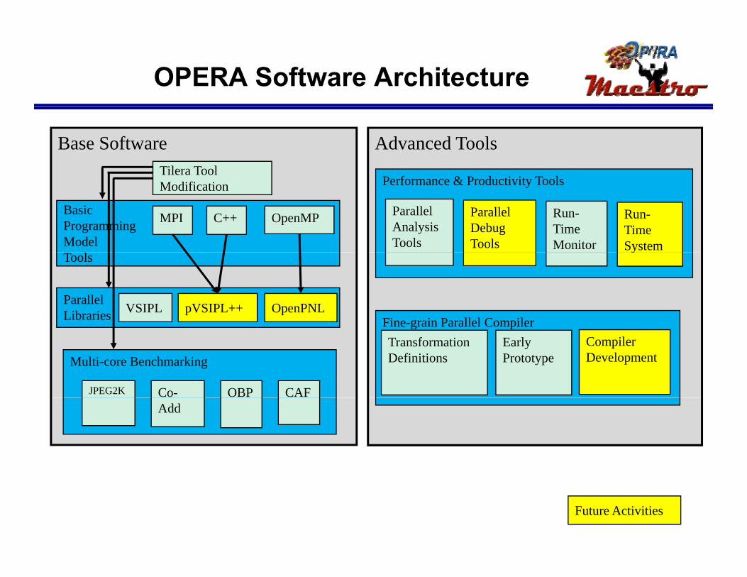
OPERA Software Architecture
Advanced ToolsBase SoftwareTilera Tool
Performance & Productivity Tools
BasicProgrammingModel
OpenMP
Modification
MPI C++
Performance & Productivity Tools
Parallel Analysis Tools
Parallel Debug Tools
Run-Time Monitor
Run-Time System
Fine-grain Parallel Compiler
ParallelLibraries
Tools
pVSIPL++VSIPL OpenPNL
y
Fine grain Parallel CompilerTransformation Definitions
Early Prototype
Compiler DevelopmentMulti-core Benchmarking
JPEG2K OBP CAFCo-Add
Future Activities
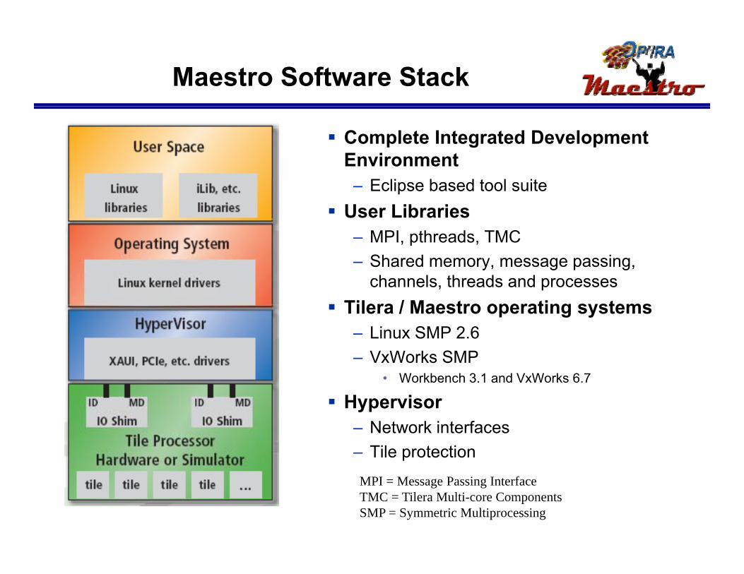
Maestro Software Stack
Complete Integrated Development Environment – Eclipse based tool suite
User Libraries– MPI, pthreads, TMC– Shared memory, message passing,
channels, threads and processes Tilera / Maestro operating systems
– Linux SMP 2.6– VxWorks SMP
• Workbench 3.1 and VxWorks 6.7
H i Hypervisor– Network interfaces– Tile protectionMPI = Message Passing InterfaceTMC = Tilera Multi-core ComponentsSMP = Symmetric Multiprocessing

OPERA Intellectual Property Rollout Benefits
Benefits to releasing OPERA IP to contractors: – Contractors can obtain the free OPERA IP if it is used in US space-
b d li ti d th id l t d IRAD / lt tbased applications and they provide related IRAD / program results to the government
– Allows industry to rapidly target US Space customers for missions with t il d lti l titailored multi-core solutions
– Leverages existing and competitive space computer board markets • Space industry has succeeded in productizing PowerPC 750 and 603
– Encourages growth of competitive multi-core architectures• Provides space industry access to a new TRL 6 RHBD multi-core processor
– Creates innovation and sources of new space processing solutionsp p g• Quickens commercial/Government acceptance of multi-core architectures • Prompts new flight computer board development for space programs
• Instigates multiple multi-core chip board solutions for space use
15
Instigates multiple multi core chip board solutions for space use
3rd party IP license fees apply only if the design is modified

Radiation Hardening By Design(RHBD) Overview
16

OPERA Radiation Requirement
Radiation operating limits and specifications– 500 Krad no SEL
Parameter Requirement Total Ionizing Dose (rd(SiO2)3 500 K
Single Event Effects (Latchup)1 500 Krad, no SEL
• TID limited by commercial Artisan memory radiation performance
– 1 hard reset per mission (10 year)
Single Event Latchup (LET in MeV-cm2/mg) ≥ 100
Single Event Effects (Functional)1
Destructive (errors/device-day) 0
Radiation testing performed in accordance radiation test plan– TID Testing
Unrecoverable (errors/device-day)4 2.80E-04
Recoverable (errors/device-day)5 2.80E-03
Data Integrity (errors/device-day) 12
– Dose Rate– Single Event Effects
Dose Rate2
Dose Rate Upset (rd(Si)/sec) ≥ 1E9
Dose Rate Survivability (rd(Si)/sec) ≥ 1E12
(1) Adams 10% Worst Case environment under worst-case operating conditions for voltage and temperature(2) Dose rate testing shall be accomplished using a 20 to 50 nsec FWHM pulse, under worst-case voltage and nominal
temperature operating conditions, for static and dynamic operation. The operation of the device under test shall be monitored for memory cell upset, I/O upset defined as a voltage excursion > Vdd/3
(3) Testing shall be done IAW MIL-T1019 7 using a Cobalt-60 source at a 50 to 300 rd(Si)/s dose-rate
17
(3) Testing shall be done IAW MIL T1019.7 using a Cobalt 60 source at a 50 to 300 rd(Si)/s dose rate(4) 1-error/device-mission (mission = 10 years); would require intervention of hard reset or power cycling(5) 1-error/device-year; taken care of through an autonomous circuit such as a watch-dog-timer

RHBD Program Vision
Enable Rad-Hard ASICs on advanced commercial fabrication processes Performancefabrication processes–High performance, low power
devices
Performance, Power,
Complexity
SpaceElectronics
–Leverage existing foundry capabilities
– IBM 9SF 90 nm CMOS
Lag
–Reduces the space electronics lagAcceptable RHBD PenaltiesHardness Goals
Area ≤ 2X
Speed ≤ 1.5X
(OPERA > 500 Krad (Si))
18
Power ≤ 2X

RHBD Design Enablement
Standard Cell Libraries• 1014 Cells • Low Power & High
S d V i t
ASIC Design Flow
Speed Variants
I/O Libraries• 500MHz LVDS• C4• Wirebond• 2.5V, 3.3V tolerant
SRAM• 1Mrad• 500Krad• 6 Types
DDR 1 & 2 Interface• High bandwidth
external storage6 Types• Generator in work
PLL• Clock
SERDES
SERDES• 10Gbit/sec Ethernet
external storage interface
19
• SERDES• DDR2
• Supports XAUI & PCI Express

Maestro Radiation Mitigation
20

RHBD Risk Mitigation Approach
Design elements validated in silicon before use Design flow validated via model / hardware
correlationcorrelation
21
PDV – Product Demonstration Vehicle ITC – Integrated Test Chip

RHBD Device Radiation Testing
2.5V dgnfet, 360/240
1E-04
1E-03 Large increase in Large increase in leakage currentleakage current
2.5V dgnfet, 360/240
1E-04
1E-03 Large increase in Large increase in leakage currentleakage current
2.5V dgnfet, 360/240
1E-04
1E-03 Large increase in Large increase in leakage currentleakage current
Annular 2.5V, dgnfet 3700/285
1E-04
1E-03
Annular 2.5V, dgnfet 3700/285
1E-04
1E-03
Annular 2.5V, dgnfet 3700/285
1E-04
1E-03
1E-08
1E-07
1E-06
1E-05
1E 04
Ids,
A
ISDHV1-Pre BI
ISDHV1-Post BI
ISDHV1-100 krad1E-08
1E-07
1E-06
1E-05
1E 04
Ids,
A
ISDHV1-Pre BI
ISDHV1-Post BI
ISDHV1-100 krad1E-08
1E-07
1E-06
1E-05
1E 04
Ids,
A
ISDHV1-Pre BI
ISDHV1-Post BI
ISDHV1-100 krad 1E-08
1E-07
1E-06
1E-05
Ids,
A
IDSHV2-Pre Bi
IDSHV2-Post BI
IDSHV2-100 krad
Very small Very small increase increase in leakage in leakage currentcurrent
1E-08
1E-07
1E-06
1E-05
Ids,
A
IDSHV2-Pre Bi
IDSHV2-Post BI
IDSHV2-100 krad
Very small Very small increase increase in leakage in leakage currentcurrent
1E-08
1E-07
1E-06
1E-05
Ids,
A
IDSHV2-Pre Bi
IDSHV2-Post BI
IDSHV2-100 krad
Very small Very small increase increase in leakage in leakage currentcurrent
1E 12
1E-11
1E-10
1E-09
1E-08I ISDHV1 100 krad
ISDHV1-250 krad
ISDHV1-500 krad
ISDHV1-750 krad
IDSHV1-1 Mrad
IDSHV1-2 Mrad
IDSHV1-168 HR ANNL1E 12
1E-11
1E-10
1E-09
1E-08I ISDHV1 100 krad
ISDHV1-250 krad
ISDHV1-500 krad
ISDHV1-750 krad
IDSHV1-1 Mrad
IDSHV1-2 Mrad
IDSHV1-168 HR ANNL1E 12
1E-11
1E-10
1E-09
1E-08I ISDHV1 100 krad
ISDHV1-250 krad
ISDHV1-500 krad
ISDHV1-750 krad
IDSHV1-1 Mrad
IDSHV1-2 Mrad
IDSHV1-168 HR ANNL1E 12
1E-11
1E-10
1E-09
1E 08 IDSHV2 100 krad
IDSHV2-250 krad
IDSHV2-500 krad
IDSHV2-750 krad
IDSHV2-1 Mrad
IDSHV2-2 Mrad
IDSHV2-168 HR ANNL1E 12
1E-11
1E-10
1E-09
1E 08 IDSHV2 100 krad
IDSHV2-250 krad
IDSHV2-500 krad
IDSHV2-750 krad
IDSHV2-1 Mrad
IDSHV2-2 Mrad
IDSHV2-168 HR ANNL1E 12
1E-11
1E-10
1E-09
1E 08 IDSHV2 100 krad
IDSHV2-250 krad
IDSHV2-500 krad
IDSHV2-750 krad
IDSHV2-1 Mrad
IDSHV2-2 Mrad
IDSHV2-168 HR ANNL1E-12
-1.0 -0.5 0.0 0.5 1.0 1.5 2.0 2.5 3.0
Vgs, VAA
1E-12-1.0 -0.5 0.0 0.5 1.0 1.5 2.0 2.5 3.0
Vgs, V
1E-12-1.0 -0.5 0.0 0.5 1.0 1.5 2.0 2.5 3.0
Vgs, VAA
1E-12-1.0 -0.5 0.0 0.5 1.0 1.5 2.0 2.5 3.0
Vgs, VBB
1E-12-1.0 -0.5 0.0 0.5 1.0 1.5 2.0 2.5 3.0
Vgs, V
1E-12-1.0 -0.5 0.0 0.5 1.0 1.5 2.0 2.5 3.0
Vgs, VBB
Nominal Transistor Design RHBD Transistor Design
Incorporating RHBD techniques as necessary, minimal d i l k b d t 2 M d[Si]device leakage can be ensured to 2 Mrad[Si]
22

PDV1 (OPERA Tile)Radiation Test Results
with RHBD II memories
23

Memory Scrubbing Summary
Maestro has built in single bit correct, double bit detect EDAC Memory scrubbing required to clear multiple bit errors
24

OPERA Program RoadmapFY2010FY2009FY2008 FY2011 FY2012
OPERA: Next Generation Space Processor Development
Space Qualified ChipRHBD Tile Device Tile Test
DTRA / DARPA – 90 nm RHBD Technology Development Program
Maestro Integrated Circuit - RHBDRHBD Libraries PDV 1 Results
TRL 6Flight RHBD DeviceRHBD Tile
OPERA Intellectual Property Release to IndustryOPERA Tile IP - 12/08 ITC
ITC Final IP - 3/10
Maestro Unverified IP - 7/10
Maestro Final IP - 12/10Devices
IP Releases
FAB
ISI-East Software
Parallel Software DevelopmentIP - 6/09 IP - 7/10
MPI, VSIPL,Benchmarks
C++, OPENMP,Fine Grain P ll li ti
Parallel Debuggerand Compiler
Updated Parallel Debugger and Compiler
Available Devices Available
Space Computer Board Development
Parallelizationp Debugger and Compiler
Estimated Board
Center for High Performance Reconfigurable Computing (CHREC) Software
Space Computer Board Industry
25
Hardened Computer Board TRL 6
Engineering Level Computer Board
Space Qualified Board
RH ASICS(As needed)
RH MemorySpace Computer Board Not Funded by OPERA
Availability Date – July 2012y
IR&D Effort

OPERA Summary
Multi-core processors offer improved performance per watt for most applications OPERA I t t d T t Chi t k f M h 2010 OPERA Integrated Test Chip on track for March, 2010 completion– PDV1 radiation testing complete and meets requirements– ITC tapeout is currently scheduled for Q4, 2009
• Tapeout date has slipped mainly due to memory timing model and design for test implementation issues
Maestro on track for December, 2010 completion (TRL 6)– 2nd pass device if required
RHBD is a viable alternative to radiation hardened by RHBD is a viable alternative to radiation hardened by process devices for select designs OPERA IP available for interested contractors / agencies
ki US b d li tiworking on US space-based applications
26