operating and maintenance instruction manual model “pbx”
TRANSCRIPT

1305 Fair Avenue • Santa Cruz, CA 95060Tel: (831) 458-0552 • Fax: (831) 458-0554— — — — — www.inovon.com — — — — —
OPERATING AND MAINTENANCEINSTRUCTION MANUAL
MODEL “PBX”TELEPHONE SWITCH
_________
TABLE OF CONTENTS
Section I - INTRODUCTION ..............................................1Product Description - Product Features -Product Applications - Product Specifications
Section II - PBX INSTALLATION .......................................3Unpacking and Inspection - Mounting -AC Mains Power - Radio FrequencyInterference (RFI) - Front Panel Indicators -Rear Panel Connectors and Indicators -Connecting the PBX - “Priority Channel”
Section III - PBX OPERATION ...........................................7Calls Outgoing From the PBX - CallsIncoming to the PBX - Formatting Auto-DialCommands - Using Two or More PBX Units -The Security Password
Section V - CIRCUIT DESCRIPTIONS .............................10Schematic Diagram Notes - The “PIC”Microcontroller - PBX Operation for OutgoingCalls - PBX Operation for Incoming Calls -20Hz Ringing Supply - DC Power Supplies -Parts Listing - Mail-Order ComponentSuppliers - Schematic Diagrams -Warranty (inside back cover)
INOVONICS WARRANTYI TERMS OF SALE: Inovonics products are sold with an un-
derstanding of “full satisfaction”; that is, full credit or refundwill be issued for products sold as new if returned to the pointof purchase within 30 days following shipment, provided thatthey are returned complete, and in “as shipped” condition.
II CONDITIONS OF WARRANTY: The following terms applyunless amended in writing by Inovonics, Inc.
A. The Warranty Registration Card supplied with the productmust be completed and returned to the factory within 10days of delivery.
B. The Warranty applies only to products sold “as new.” It isextended only to the original end-user and may not betransferred or assigned
C. The Warranty does not apply to damage caused by mis-use, abuse or accident. The Warranty is automaticallyvoided by unauthorized attempts at repair or modification,or if the serial identification tag has been removed or al-tered.
III TERMS OF WARRANTY: Inovonics, Inc. products are war-ranted to be free from defects in materials and workmanship.
A. Any discrepancies noted within 90 days of the date of de-livery will be repaired free of charge, or the equipment willbe replaced at the option of Inovonics.
B. Additionally, parts for repairs required between 90 daysand one year from the date of delivery will be supplied freeof charge. Labor for factory installation of such parts willbe billed at Inovonics’ prevailing “shop rate.”
IV RETURN OF GOODS FOR FACTORY REPAIR:
A. Equipment will not be accepted for Warranty or other re-pair without a Return Authorization (RA) number issued byInovonics prior to its return. An RA number may be ob-tained by calling the factory, and should be prominentlymarked on the outside of the shipping carton.
B. Equipment must be shipped prepaid to Inovonics. Ship-ping charges will be reimbursed for valid Warranty claims.Damage sustained as a result of improper packing for re-turn to the factory is not covered under terms of the War-ranty and may occasion additional charges.

— 1 —
Section I
INTRODUCTION
Product Description
Inovonics’ “PBX” is a telephone switching “mini-system.” Itallows up to seven dial-up devices (modems, fax machines,alarm boxes, telephone sets, etc.) to share a single central officetelephone line, both for outgoing and for incoming calls. ThePBX delivers central office dial tone to the first modem or otherdevice which goes off-hook to originate a call. Calls incoming tothe PBX are directed to the selected device with a touch-tone®
access command from the calling party.
Product Features
Features of the Inovonics PBX include:• Easy installation with standard RJ11 jacks for telco line
and subscriber equipment.• Two or more PBX units may be daisy-chained to ac-
commodate additional dial-up devices.• 90-volt / 20Hz ringing voltage generated internally.• Powered by mains-voltage adapter (supplied), or by Un-
interruptible Power Supply (UPS) at user’s option.
Product Applications
The PBX finds primary utility in remote, unattended equip-ment installations which may be limited to a single central of-fice phone line. Such installations might include broadcasttransmitter sites, emergency power plants, pumping stations,radio repeater huts and weather monitoring locations. In short,any installation of electronic equipment for monitoring, alarmor dial-up interrogation which requires occasional, intermittentaccess to a standard telephone line.

— 2 —
Product Specifications
Central Office Compatibility: Standard 48-volt, 40mA sub-scriber loop equipped for touch-tone service. Connectionvia RJ11 jack, polarity protection provided.
Subscriber Set Compatibility: Accepts any modem, tel-set,fax machine, alarm equipment, etc. intended for direct con-nection with a touch-tone-equipped central office telephoneline. Connections via RJ11 jacks.
Panel Indicators: POWER, C.O. CONNECT, MODEM CON-NECT on front panel. Rear-panel indicators next to eachjack light when that device goes off-hook.
Power Requirement: 12VAC at 500mA. A “wall-transformer” power supply is provided. The PBX will alsooperate from an external DC source between 15V and 20V.
Size and Weight: 2”H x 6”W x 8”D; 4 lbs. (shipping).

— 3 —
Section II
PBX INSTALLATION
Unpacking and Inspection
Inspect for possible shipping damage immediately upon receiptof the equipment. If damage is suspected, notify the carrier atonce, then contact Inovonics.
We recommend that you set-aside the original shipping cartonand packing materials for possible reuse. In the event of returnfor Warranty repair, shipping damage sustained as a result ofimproper packing may invalidate the Warranty!
IT IS VERY IMPORTANT that you complete and re-turn the Warranty Registration Card found at the frontof this Manual. Not only does this assure coverage ofthe equipment under terms of the Warranty, and pro-vide some means of trace in the case of lost or stolengear, but the user will automatically receive specificSERVICE OR MODIFICATION INSTRUCTIONSshould they be issued by Inovonics.
Mounting
The Inovonics PBX is packaged in a plastic box with rubberfeet. Though no provision is included for rack-mounting, theunit may be set atop any convenient rack-mounted chassis, solong as at least 2U of panel space above the “host” equipment isleft open to access the PBX. Alternatively, the PBX may be lo-cated next to the telephone company’s “demarc” and fastenedto the wall or mounting board with a couple of small anglebrackets from the hardware store. Short sheet-metal screwswill secure the brackets to the plastic enclosure.
AC Mains Power
The PBX is supplied with a 115-volt, “wall-mounted trans-former” power supply. The actual power delivered to the PBXis 12 volts AC at about 500mA. Though the input power to thePBX is thus defined, we nonetheless recommend that you usethe supplied “wall wart” whenever possible.

— 4 —
If the PBX is expected to function during a mains power failure,whatever standby supply is available for the other equipmentcan probably operate the PBX as well. If this is a 115-volt ACmains supply, no special provision is necessary. If, on the otherhand, other equipment at the location draws power from a bat-tery backup, the PBX may be powered from this as well. Ap-propriate DC may be fed directly in to the rear-panel connectorlabeled POWER (12VAC) without regard to supply polarity.This DC feed should be pre-regulated to a value between 15VDCand 20VDC. If, for example, the standby power source is a 24-volt battery supply, a simple series regulator may be arrangedusing a common “3-terminal” voltage regulator integratedcircuit such as the National Semiconductor LM7815CT.
Radio Frequency Interference (RFI)
We have anticipated that the PBX may be installed in the im-mediate proximity of broadcast transmitters or 2-way radioequipment. Nevertheless, please practice some care in locatingthe unit away from abnormally high RF fields.
Front Panel Indicators
POWER This LED lights only when the proper voltage isdelivered to the PBX. An voltage somewhat belowthe required input will cause the indicator to goout, though the unit may appear to function prop-erly.
C.O.CONNECT
This indicator lights whenever the central office(telco) line is engaged, either for calls outgoingfrom, or incoming to, the PBX.
MODEMCONNECT
This lights when one of the connected devices(modem, etc.) is active. For an outgoing call, thisLED will light concurrently with the C.O. CON-NECT indicator as the telco line is seized. Whenthe PBX answers an incoming call, this LED willlight once the desired device has been selectedwith the appropriate touch-tone address, rung-upand has answered.

— 5 —
Rear Panel Connectors and Indicators
POWER(12 VAC)
This “coaxial power” connector mates with theplug molded onto the end of the “wall wart” powersupply cord. Nominal connector dimensions are5mm O.D. by 2.5mm I.D. This is a common con-nector (Radio Shack #274-1568), should one be re-quired for alternative power accommodations.(Note particulars at the top of the previous page.)
TEL LINE This US-standard RJ11 jack connects the PBX tothe tip and ring of the central office telephone line.Use any standard, 4-conductor “modular-to-modular” telephone set mounting cord, such asRadio Shack #279-347 (6-foot), #279-374 (12-foot)or #279-356 (25-foot).
MODEMS(1 – 7)
These seven RJ11 jacks interconnect the PBX withthe various pieces of equipment which will sharethe common central office telephone line. Thesame “modular-to-modular” cables may be used aslisted above. NOTE: MODEM 7 is designated a“Priority Channel.” See explanation below.
Each jack has an associated LED to indicate whichpiece of equipment is connected to the central of-fice line.
Connecting the PBX
As hinted in the foregoing description of rear-panel appoint-ments, the “wall-wart” power supply is plugged into thePOWER (12 VAC) socket. The central office line is connected tothe TEL LINE jack, and modems, etc. are assigned to the sevenMODEM jacks. Nothing could be simpler, could it?
The use of a second PBX to accommodate additional equipmentis covered on Page 8.
“Priority Channel”
The MODEM 7 jack has been designated a “priority channel.”Whenever the device plugged into this jack goes off-hook:1) any existing outgoing or incoming connection is unceremoni-ously “dumped,” 2) the central-office line is restored to an idlecondition with a two-second delay, and 3) MODEM 7 equipmentis connected directly to the line.

— 6 —
If an incoming call is in progress when the MODEM 7 “priority”device seizes the line, the priority device may not immediatelyreceive and recognize dial tone. Modern modems will notblindly “dial away” into a dead connection, but will hang upand try the call again. Results may well depend on the commu-nication protocol of the equipment which originated the inter-rupted call. Once communication has been broken by the calledmodem being disconnected, the originating equipment mayimmediately hang up and then attempt to re-establish commu-nication. You may wish to edit the dialing routine of such gear,adding a “wait” command to allow the priority device a chanceto seize the line.
MODEM 7, the “priority channel,” should be assigned to equip-ment with a vital or sensitive function; a fire or water-levelalarm, for instance. Another candidate might be a remote con-trol system with a paging provision which automatically sum-mons a technician in an emergency.

— 7 —
Section III
PBX OPERATION
Calls Outgoing From the PBX
In the idle state of the PBX, the first modem or other equip-ment to go off-hook will seize the telco line and receive centraloffice dial tone. Once this connection is made, the equipmenthas a direct, “metallic” connection with the central office linewhich will be maintained without interruption until the modem“hangs-up.” The PBX does not have a call-duration “timeout”provision. The single exception to this rule is an off-hook by“priority channel” equipment connected to the MODEM 7 jack.Anything connected to this jack has immediate priority over anyoutgoing or incoming call. (See Page 5.)
Calls Incoming to the PBX
Assuming an idle state, an incoming call will be answered bythe PBX on the very first ring. When the PBX goes off-hook, itdoes not return a “second dial tone.” It will wait for a validtouch-tone command for only 10 seconds before hanging up andreleasing the line. During this 10-second “window,” the PBXwill respond to the proper “security password,” followed by asingle-digit “device number” to ring the desired equipment.
The security password is: ∗ - 5 - # (“star,” the number “5” andthe “number symbol” or “pound sign”). This should be fol-lowed immediately by the number of the device to be rung. Forinstance, ∗ - 5 - # - 3 would ring the device connected to theMODEM 3 jack. If the PBX receives an incorrect security pass-word, or no touch-tone command at all, it will hang up at theend of the 10 second window.
When it receives the proper “access string,” the PBX appliesringing voltage to the selected device. The ringing signal con-forms to the standard established in the halcyon days of theBell System: 90 volts AC at 20Hz, one second on, two secondsoff. The PBX will disconnect if the selected device does not an-swer within ten rings.

— 8 —
Formatting Auto-Dial Commands
When equipment connected to the PBX is to be called-up andinterrogated automatically from a “home” location, the pro-grammed dialing command must be formatted to insert the se-curity password and device address.
Since the PBX has a fixed, 10-second window to receive this in-formation, it is important to know how soon this window opensafter the last digit of the telephone number is entered. Withinthe same exchange this could be almost instantaneous. Sincenearly all telephone exchanges now utilize digital switchingequipment, there is a very short connection delay even on acoast-to-coast call. Nevertheless, it is worth placing a call to thePBX from a conventional touch-tone telephone to confirm theaverage connection time in seconds.
Most modems which offer programmed dialing are able to insertadditional access codes, area codes and pauses in the dialingprocess. Though these usually precede the telephone number tobe dialed, there is no reason why they cannot be placed after thenumber. You must consult the specific instructions suppliedwith the auto-dialing modem, of course, but many modems ac-cept commas in the dialing string to initiate one-second pauseswherever they are inserted. If the connection delay is estab-lished at one or two seconds, insert two or three commas be-tween the telephone number and the additional digits. For in-stance, dialing:
5 - 5 - 5 - 1 - 2 - 1 - 2 - , - , - ,- ∗- 5 - # - 3
would dial the PBX, pause three seconds while the connectionwas completed and the PBX has answered, then forward the se-curity password and ring device number 3.
The PBX returns “audible ringing” to the calling party as theselected device is actually rung-up. This acknowledges receiptof the proper security password and monitors progress of theconnection at the remote site.
Using Two or More PBX Units
One might ventue that a half-dozen dial-up devices could taxthe limit of a single telco line, even when the intermittent na-ture of equipment usage is taken into account. There may beinstances, however, when additional equipment may safely beaccommodated by using two or more PBX units.

— 9 —
Interconnection is simple. The TEL LINE jack of the second,“slave” unit is plugged into one of the MODEM jacks of the first,“master” PBX. You would probably not choose MODEM 7,unless all equipment accessing the “slave” PBX wants to be as-signed priority over devices plugged into the “master.”
Don’t forget that the dialing routine for an incoming call mustcontain a second, identical security password and a device ad-dress to reach equipment plugged into the “slave.” As an ex-ample, let’s assume that the “slave” is plugged into the MODEM2 jack of the “master” PBX. To reach “slave” device number 4,you would need to dial:
5 - 5 - 5 - 1 - 2 - 1 - 2 - , - , - ,- ∗- 5 - # - 2 - , - , - ∗- 5 - # - 4
The Security Password
All Inovonics PBX units respond to the same security password:
∗- 5 - # . This gives a modest level of protection from casual“hackers,” though it is assumed that modems or other dial-upequipment connected to the PBX will incorporate additional se-curity protection if it is deemed necessary.
The PBX security password cannot be changed in the field. It isresident in ROM, integral with PBX microprocessor control.

— 10 —
Section IV
CIRCUIT DESCRIPTIONS
Schematic Diagram Notes
This explanation of circuit operation refers to the several pagesof schematics which follow this text.
Schematic component reference designations may at first ap-pear to be annotated in a somewhat haphazard manner. Ratherthan annotate the schematic in a logical sequence, we chose in-stead to designate the components on the circuit boards follow-ing their physical placement, top-to-bottom, left-to-right. It isour expectation that this practice will prove the more usefulduring troubleshooting, making it easier to locate the physicalpart or test point from an analysis of the circuitry.
PBX circuitry is contained on two, double-sided printed circuitboards. The larger “main board” is fastened to the lower case-half of the plastic cabinet. DC power and 20Hz ringing sup-plies, common-control logic, central office line circuitry andcomponents associated with MODEMS 5, 6 and 7 are located onthis board. Schematic reference designations on this board be-gin with “1” (R1, C1, IC1, etc.).
The “auxiliary board,” which plugs into the main board, con-tains circuitry for MODEMS 1, 2, 3 and 4. Components on thisboard are in the “200” series (R201, Q201, etc.).
The “PIC” Microcontroller
The PBX employs an integrated circuit called a “PIC,” or Pe-ripheral Interface Controller, IC3 on the schematic diagram.The PIC is a simple, single-chip microprocessor with on-board,factory-programmed ROM memory. Though limited in intelli-gence, it is ideal for the elementary logic and simple controlfunctions required for PBX operation.
Each separate function of the PIC will be described along withthe circuitry it supports.

— 11 —
PBX Operation for Outgoing Calls
Assuming an idle state, as MODEM 1 goes off-hook Q207 isturned on by current through R217 and the normally-closedcontacts of relay K204. IC1 routes a corresponding 3-bit binaryaddress to the PIC microcontroller, IC3.
The PIC actuates relay K204 through a binary decoder, IC2,and driver transistor Q208. It also actuates relay K5, connect-ing MODEM 1 to the telephone line through normally-closedcontacts of relay K4. The front-panel MODEM CONNECT indi-cator lights when K5 is actuated.
OP1 is an optical coupler which monitors central-office loopcurrent. About 5mA flows through the coupler, the balance isshunted by transistor Q7. When MODEM 1 finally hangs up,OP1 turns off and the PIC restores an idle state.
For the duration of the call, the PIC will ignore an off-hookfrom any other device, except for the device connected to theMODEM 7 jack. Should this device go off-hook during a call inprogress, the PIC immediately aborts that call, restores an idlecondition, then waits for 2 seconds before connecting the MO-DEM 7 equipment to the central-office line. MODEM 7 is a “pri-ority channel” which will interrupt all calls, outgoing and in-coming alike.
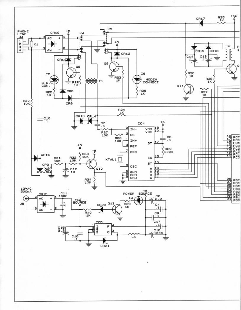
PBX Operation for Incoming Calls
Central-office ringing is detected by optical coupler OP2. C7blocks central-office DC. The first few cycles of ringing voltagedrive Q10 into saturation, this logic alerts the PIC to an in-bound call. The PIC then actuates relay K4 through transistorQ8, lighting the C.O. CONNECT indicator as well. A DC paththrough the primary of line-coupling transformer T1 gives anoff-hook to the central-office line, thus “answering” the incom-ing call. This initiates the 10-second “window” during whichthe proper security password must be received, otherwise thePIC will hang up and restore an idle state.
The secondary of T1 is coupled to IC4, a touch-tone decoderchip. Binary touch-tone logic from IC4 is routed to the PIC.The PIC looks for the valid security password followed by a sin-gle-digit device address, MODEM 1, for this example. When thisinformation is properly decoded, the PIC actuates K204 and ap-plies the 90-volt, 20Hz ringing voltage through normally-closedcontacts of K5. The PIC is programmed to restore an idle state

— 12 —
if the device does not answer within 10 rings. Audible ringing isreturned to the calling party with a sample of the 20Hz square-wave coupled through R## into T1.
When the device answers, DC current supplied by R33 throughCR14 is sensed by the loop-current monitor, OP1. The PICthen actuates K5 and releases K4 to connect the MODEM 1 de-vice directly to the central-office line. OP1 continues to moni-tor the loop current, and when the incoming call is completedthe PIC restores the PBX to an idle state.
20Hz Ringing Supply
To generate the 90VAC ringing voltage, the PIC generates acomplex, “composite” waveform at pin 24. This is a 10kHzsquarewave “carrier” keyed on-and-off at the 20Hz ringing fre-quency, the 20Hz having a 1-second “on” period followed by 2seconds “off.” The composite waveform saturates Q12, drivingthe primary of T2. The high frequency carrier allows a rela-tively small transformer to step-up the 20Hz ringing voltage.
CR15 and CR16 perform a voltage-doubling “recovery” of the20Hz component of the composite waveform. Q11 is an activepart of this recovery process, being driven at the 20Hz rate bypin 23 of the PIC. C10 and C11 remove the 10kHz “carrier”frequency.
DC Power Supplies
Raw AC from the secondary of the 12VAC wall-mounting powertransformer is applied to bridge rectifier CR12. This rectifieralso allows the PBX to be powered from an appropriate externalDC supply without regard to input polarity.
Unregulated DC from CR12 has a value of approximately +15volts. When the PBX is powered by an external “standby” DCsupply, the applied DC should be close to this value. Shouldraw DC fall much below 15 volts, Q13, held in saturationthrough 12-volt zener diode CR17, will extinguish front-panelPOWER indicator I4.
IC5, along with L1 and other associated components, is aswitching regulator to transform the raw +15VDC to a regu-lated +5VDC supply for the digital ICs and other control cir-cuitry.

— 13 —
Parts Listing
Component parts used in the PBX are listed either en-masse, orindividually by schematic component reference designation.The listing may, or may not, specify a manufacturer by name.When no manufacturer is called-out, the term “open mfgr.” ad-vises that any manufacturer’s product is acceptable, as long asit carries the requisite generic part number.
If a component is not listed at all, this means that we do notconsider it a typical replacement item. Should you need to iden-tify or order an unlisted part, call, write or fax us with a briefdescription. We’ll do our best to figure out what you need andhow to get it to you.
Unless specifically noted by component reference designationbelow, capacitors are specified as follows:
a) 100pF to 0.47µF are metalized mylar or polyester. Wholenumber “P” values are picofarads, decimal values are micro-farads; ±5%, 50VDC or better. The style used in the 701 isthe “minibox” package with a lead spacing of 0.2 inch.(Wima MKS-2 or FKC-2 series, CSF-Thompson IRD series,of Roederstein KT-1808 or KT-1871 series.)
b) 1.0µF and above are radial-lead electrolytics, 25VDC;(open mfgr.)
C2,6,13,14 Capacitor, Monolithic Ceramic,0.1µF, 50V; (open mfgr.)
C8 Capacitor, Electrolytic, Axial Leads,1000µF, 35V; (open mfgr.)
C10,11 Capacitor, Electrolytic, Radial Leads,1.0µF, 160V; (open mfgr.)
C15 Capacitor, Electrolytic, Radial Leads,1000µF, 10V; (open mfgr.)
CR1,2,3,5,6,8,9,13,201,203,204
Diode, Silicon Signal; (open mfgr.) 1N4151
CR4,14,15,16
Diode, Silicon Rectifier; (open mfgr.) 1N4005
CR7,12 Bridge Rectifier; ##CR10,11 Diode, Zener, 3.9V; (open mfgr.) 1N5228B
CR17 Diode, Zener, ##; (open mfgr.) 1N##CR18 Diode, Power Schottky; (open mfgr.) 1N5820

— 14 —
CRES1 Ceramic Resonator, 4MHz; ##I1-3,
201-204LED Indicator, diffused pastel red,
T-1 package; Stanley MVR 3378SI4 LED Indicator, diffused pastel green,
T-1 package; Stanley MPG 3878SI5,6 LED Indicator, diffused pastel yellow,
T-1 package; Stanley MAY 3378SIC1 Integrated Cct.; (open mfgr.) 74HC148IC2 Integrated Cct.; (open mfgr.) 74HC138IC3 Integrated Cct.; SPECIAL FACTORY-
PROGRAMMED “PIC,” type 16C62A;Order by designation, reference Model PBX.
IC4 Integrated Cct.; ## CM8870PIIC5 Integrated Cct.; National LM2575-5 (Uses Aavid
574602 B03700 Heat Fin)J1-4,
201-204Connector, RJ11 “Modular Telephone Jack”;
Mouser ##J5 Connector, Power Input; Mouser 163-5004
K1-5,201-204
Relay, DPDT, 5V Coil; Mouser ##
L1 Inductor, Switching Supply; Renco RL1952OP1,2 Optical Coupler; NEC 2501
Q1,3,5,7,8,9,10,13,14,
201,203,205,207
Transistor, NPN; (open mfgr.) 2N3904
Q2,4,6,202,204,206,208
Transistor, PNP; (open mfgr.) 2N3906
Q11 Transistor, NPN; (open mfgr.) MPSA42Q12 Transistor, NPN; (open mfgr.) TIP120
All fixed resistors are ¼-watt, 5% carbon film type, value perschematic diagram.
T1 Transformer, Telephone Coupling;Mouser ##
T2 Transformer, Miniature Audio;Mouser ##
— Power Transformer, wall-mounted,12.0 VAC @ 0.5A; Jameco 101258
X1 Protector, Voltage “Crowbar”; ##XTAL1 Crystal, 3.579545MHz; (open mfgr.)

— 15 —
Mail-Order Component Suppliers
Certain mail-order electronics distributors have proven them-selves reputable suppliers of both large and small quantities ofparts. Any semiconductor, IC, capacitor, resistor or connectorused in the Model 701 is probably available from one or more ofthese firms. Each supplier publishes a full-line catalog availablefree for the asking.
Mouser Electronics — Call (800) 346-6873
Digi-Key Electronics — Call (800) 344-4539
ACTIVE (div. of Future Electronics) — Call (800) 677-8899
Schematic Diagrams
The following pages contain a complete schematic diagram ofthe Model PBX Telephone Switch. The original drawing hasbeen disassembled and reduced to fit the diminutive format ofthis Manual. The presbyopia-challenged may obtain a full-sizediagram, simply for the asking, by sending a self-addressed 9-by-12-inch envelope to Inovonics.

— 16 —

— 17 —

— 18 —

— 19 —

— 20 —