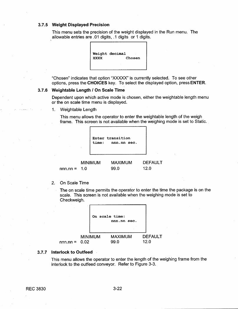
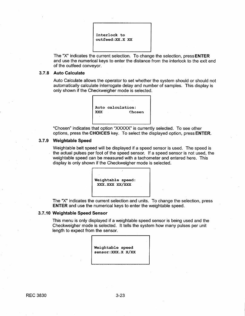
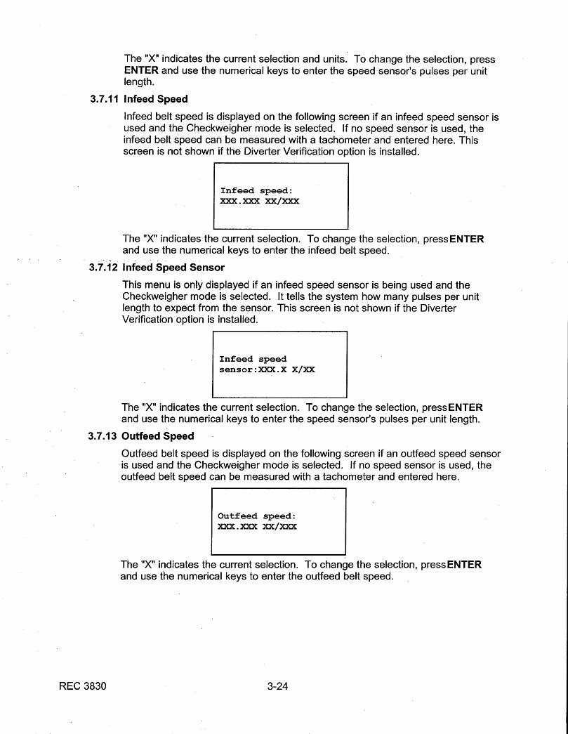
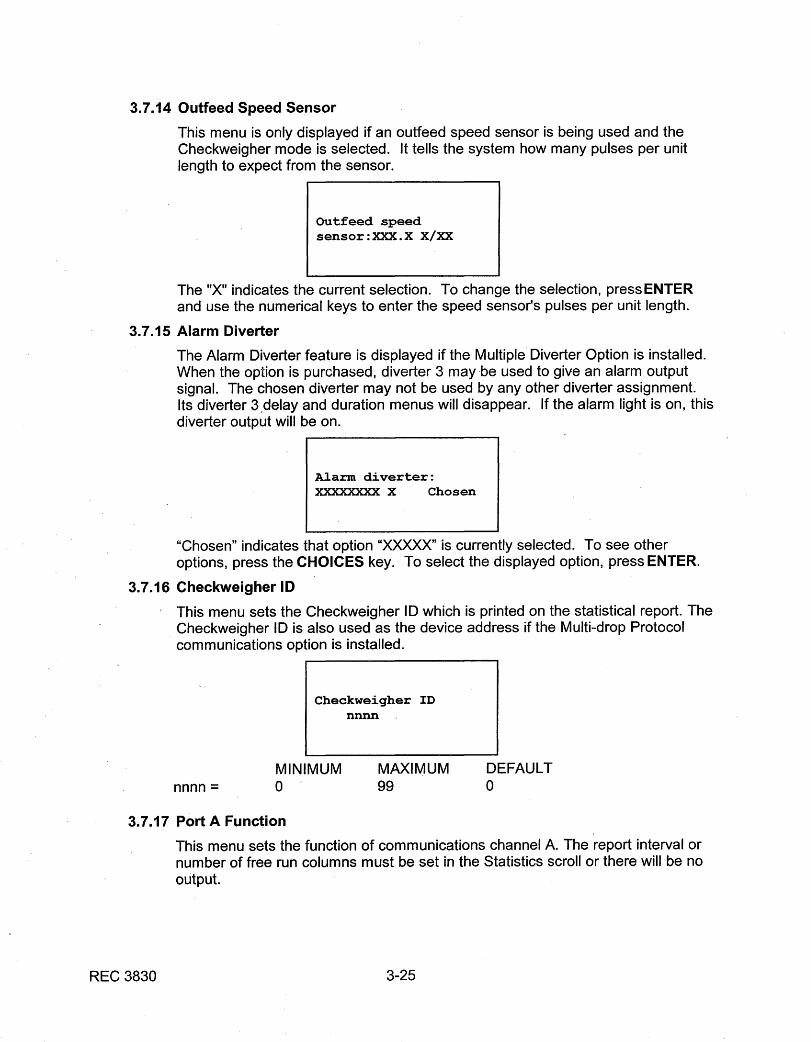
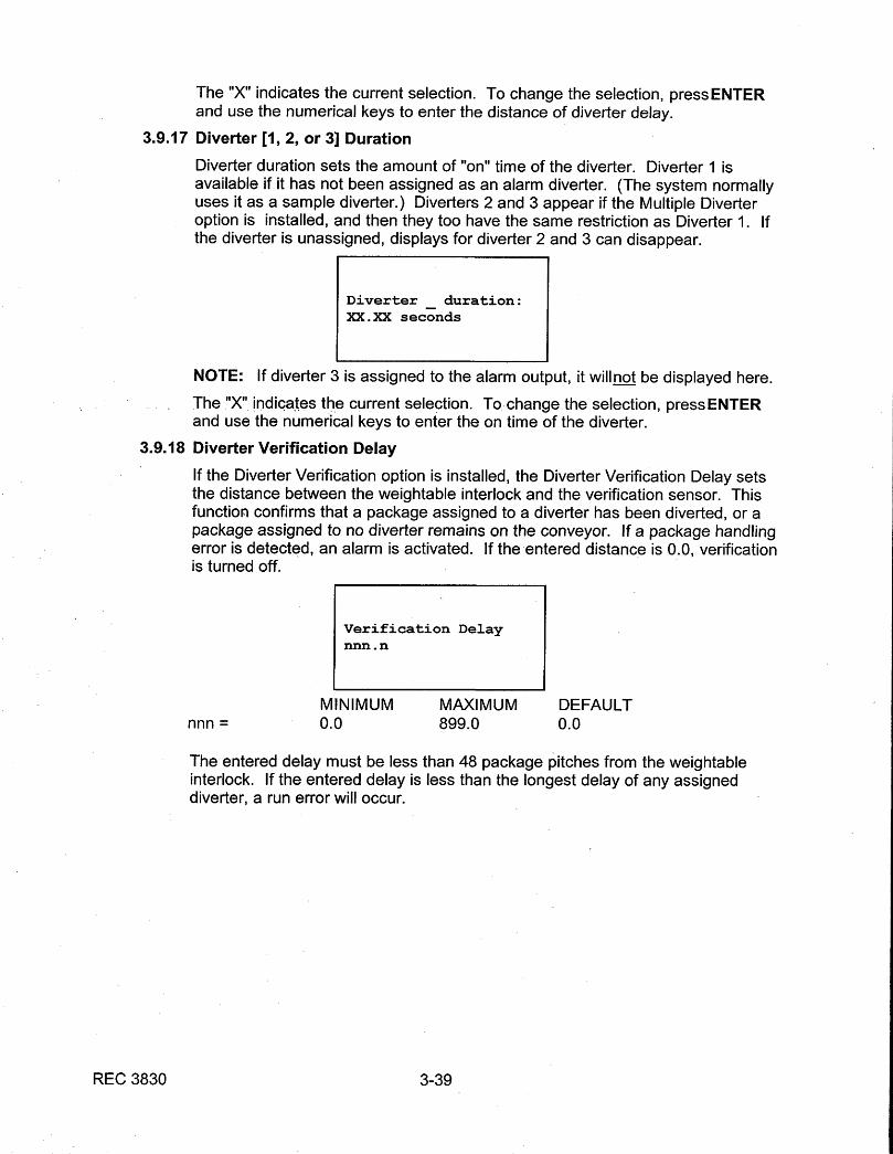
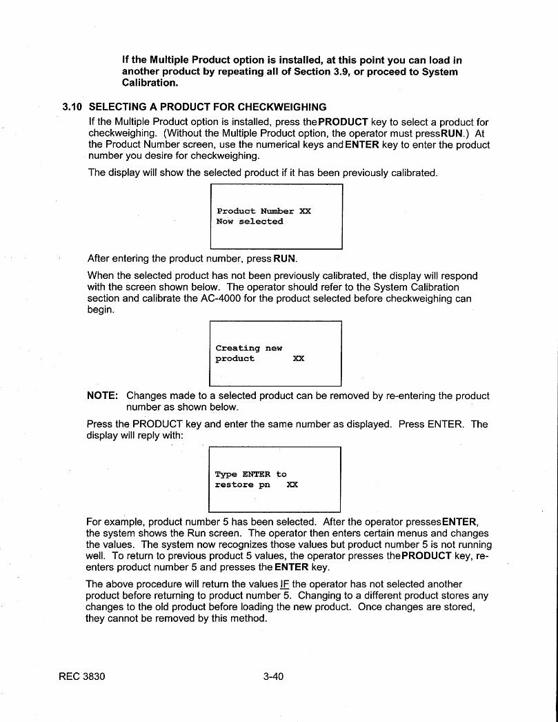
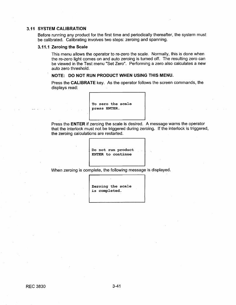
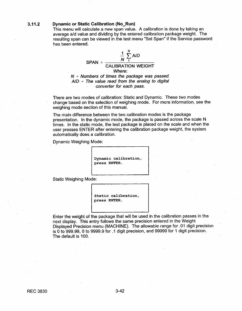
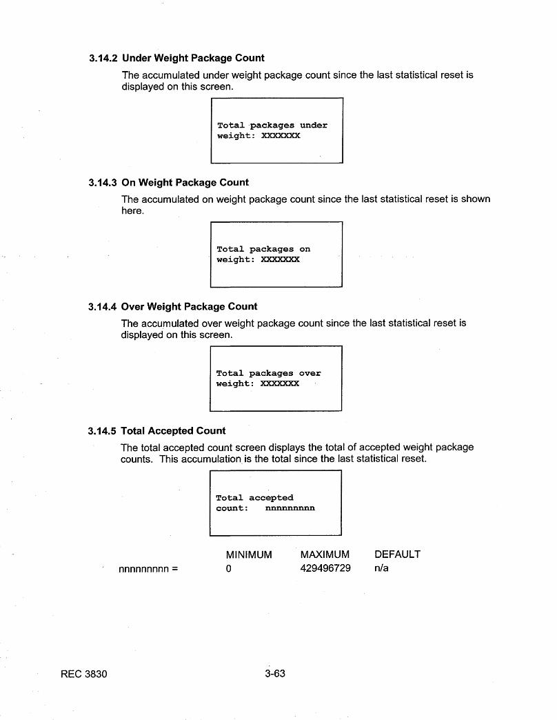
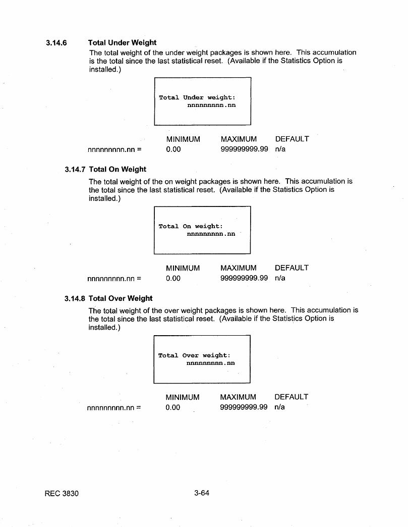
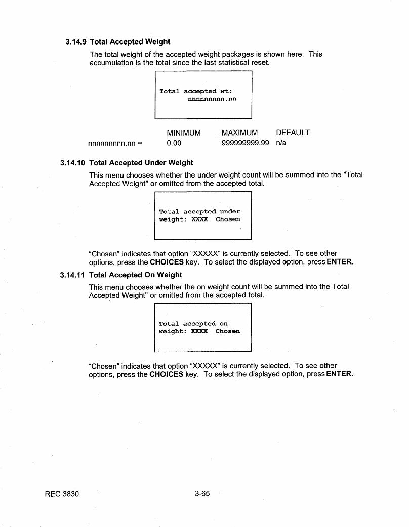
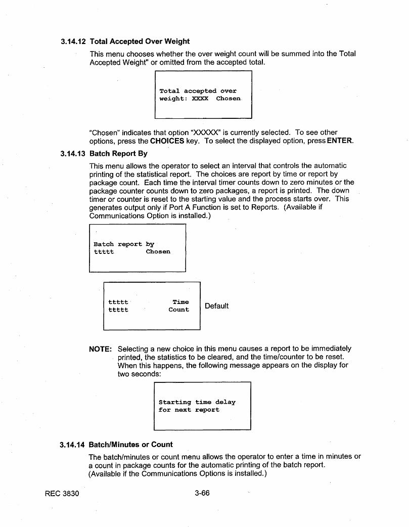
operating and service manual thermo electron ac …20and$20service$20manual$20ac4$20... ·...
TRANSCRIPT

REC 3829 REV M 10/05PART NO. 045716
OPERATING AND SERVICE MANUAL
THERMO ELECTRON
AC-4000 CONTROLLER

REC 3829 II
REVISION HISTORY
REVISION A OCTOBER 1993REVISION B JANUARY 1994REVISION C APRIL 1994REVISION D FEBRUARY 1995REVISION E AUGUST 1995REVISION F NOVEMBER 1995REVISION G SEPTEMBER 1997REVISION H DECEMBER 1997REVISION J MAY 1998REVISION K FEBRUARY 2000REVISION L SEPTEMBER 2000REVISION M OCTOBER 2005
COPYRIGHT 1993, 1994, 1995, 1997. 1998, 2000 BY THERMO ELECTRON, INC
THIS DOCUMENT IS CONFIDENTIAL AND IS THE PROPERTY OF THERMO. IT MAY NOT BECOPIED OR REPRODUCED IN ANY WAY WITHOUT THE EXPRESS WRITTEN CONSENT OFTHERMO. THIS DOCUMENT ALSO IS AN UNPUBLISHED WORK OF THERMO. THERMOINTENDS TO AND IS MAINTAINING THE WORK AS CONFIDENTIAL INFORMATION. THERMOALSO MAY SEEK TO PROTECT THIS WORK AS AN UNPUBLISHED COPYRIGHT. IN THEEVENT OF EITHER INADVERTENT OR DELIBERATE PUBLICATION, THERMO INTENDS TOENFORCE ITS RIGHTS TO THIS WORK UNDER THE COPYRIGHT LAWS AS A PUBLISHEDWORK. THOSE HAVING ACCESS TO THIS WORK MAY NOT COPY, USE OR DISCLOSE THEINFORMATION IN THIS WORK UNLESS EXPRESSLY AUTHORIZED BY THERMO.
PLEASE READ AND OBSERVE THE FOLLOWING SAFETYPRECAUTIONS FOUND THROUGHOUT THIS MANUAL.
DANGER
FAILURE TO OBSERVE WILL CAUSE VERY SERIOUS PERSONAL INJURY OR DEATH.
WARNING
FAILURE TO OBSERVE COULD CAUSE SERIOUS PERSONAL INJURY.
CAUTION
FAILURE TO OBSERVE MAY CAUSE MINOR OR MODERATE PERSONAL INJURYOR DAMAGE TO THE EQUIPMENT.

REC 3829 III
THERMO RAMSEY ICORE PRODUCTS
AC-4000 CONTROLLER
TABLE OF CONTENTS
CHAPTER TITLE PAGE
1.0 INTRODUCTION . . . . . . . . . . . . . . . . . . . . . . . . . . . . . . . . . . . . . . . . . . . . . . . . . 1-1
1.1 GENERAL DESCRIPTION . . . . . . . . . . . . . . . . . . . . . . . . . . . . . . . . 1-1
1.1.1 Applications . . . . . . . . . . . . . . . . . . . . . . . . . . . . . . . . . . . . 1-1
1.1.2 System Description . . . . . . . . . . . . . . . . . . . . . . . . . . . . . . 1-1
1.1.3 Operation . . . . . . . . . . . . . . . . . . . . . . . . . . . . . . . . . . . . . . 1-1
1.1.4 Features . . . . . . . . . . . . . . . . . . . . . . . . . . . . . . . . . . . . . . 1-3
1.2 OPTIONS . . . . . . . . . . . . . . . . . . . . . . . . . . . . . . . . . . . . . . . . . . . . . 1-4
1.2.1 15 Programmable Product Set-Ups . . . . . . . . . . . . . . . . . . 1-4
1.2.2 Statistics (STATS) . . . . . . . . . . . . . . . . . . . . . . . . . . . . . . . 1-4
1.2.3 Multiple Diverter . . . . . . . . . . . . . . . . . . . . . . . . . . . . . . . . . 1-4
1.2.4 Diverter Verification . . . . . . . . . . . . . . . . . . . . . . . . . . . . . . 1-4
1.2.5 Communications (COM) . . . . . . . . . . . . . . . . . . . . . . . . . . 1-4
1.3 WARRANTY . . . . . . . . . . . . . . . . . . . . . . . . . . . . . . . . . . . . . . . . . . . 1-7
2.0 INSTALLATION . . . . . . . . . . . . . . . . . . . . . . . . . . . . . . . . . . . . . . . . . . . . . . . . . . 2-1
2.1 GENERAL . . . . . . . . . . . . . . . . . . . . . . . . . . . . . . . . . . . . . . . . . . . . . 2-1
2.2 SAFETY PRECAUTIONS . . . . . . . . . . . . . . . . . . . . . . . . . . . . . . . . . 2-1
2.2.1 Occupational Safety and Health Act (OSHA) . . . . . . . . . . . 2-2
2.3 STORAGE . . . . . . . . . . . . . . . . . . . . . . . . . . . . . . . . . . . . . . . . . . . . . 2-2
2.4 UNCRATING & INSPECTION . . . . . . . . . . . . . . . . . . . . . . . . . . . . . . 2-2
2.5 EQUIPMENT LOCATION . . . . . . . . . . . . . . . . . . . . . . . . . . . . . . . . . 2-3
2.6 INSTALLATION . . . . . . . . . . . . . . . . . . . . . . . . . . . . . . . . . . . . . . . . . 2-4
2.6.1 Initial Power On . . . . . . . . . . . . . . . . . . . . . . . . . . . . . . . . . 2-4
3.0 SOFTWARE . . . . . . . . . . . . . . . . . . . . . . . . . . . . . . . . . . . . . . . . . . . . . . . . . . . . 3-1
4.0 MAINTENANCE . . . . . . . . . . . . . . . . . . . . . . . . . . . . . . . . . . . . . . . . . . . . . . . . . . 4-1
4.1 GENERAL . . . . . . . . . . . . . . . . . . . . . . . . . . . . . . . . . . . . . . . . . . . . . 4-1
4.2 SERVICE & REPAIR . . . . . . . . . . . . . . . . . . . . . . . . . . . . . . . . . . . . . 4-1
TABLE OF CONTENTS(continued)
CHAPTER TITLE PAGE
REC 3829 IV
4.3 COMPONENT REPLACEMENT PROCEDURES (ELECTRICAL) . . . 4-1
4.3.1 Display Board Assembly Replacement . . . . . . . . . . . . . . . 4-1
4.3.2 Display Module Replacement . . . . . . . . . . . . . . . . . . . . . . 4-2
4.3.3 Communication Board Replacement . . . . . . . . . . . . . . . . . 4-2
4.3.4 CPU Board Replacement . . . . . . . . . . . . . . . . . . . . . . . . . . 4-4
4.3.5 Analog Board Replacement . . . . . . . . . . . . . . . . . . . . . . . . 4-4
4.3.6 Distribution Board Replacement . . . . . . . . . . . . . . . . . . . . 4-6
4.3.7 Front Panel Replacement . . . . . . . . . . . . . . . . . . . . . . . . . 4-8
4.3.8 Motor Speed Control Module Replacement . . . . . . . . . . . 4-10
4.3.9 Cold Start Procedure . . . . . . . . . . . . . . . . . . . . . . . . . . . . 4-10
4.4 TROUBLESHOOTING . . . . . . . . . . . . . . . . . . . . . . . . . . . . . . . . . . 4-11
5.0 REPLACEMENT PARTS . . . . . . . . . . . . . . . . . . . . . . . . . . . . . . . . . . . . . . . . . . . 5-1
5.1 GENERAL . . . . . . . . . . . . . . . . . . . . . . . . . . . . . . . . . . . . . . . . . . . . . 5-1
5.2 ORDER INFORMATION . . . . . . . . . . . . . . . . . . . . . . . . . . . . . . . . . . 5-1
5.3 PARTS LIST INDEX . . . . . . . . . . . . . . . . . . . . . . . . . . . . . . . . . . . . . 5-2
5.3.1 Return Material Authorization . . . . . . . . . . . . . . . . . . . . . . . 5-3
6.0 AC-4000 OPTIONS . . . . . . . . . . . . . . . . . . . . . . . . . . . . . . . . . . . . . . . . . . . . . . . 6-1
6.1 GENERAL . . . . . . . . . . . . . . . . . . . . . . . . . . . . . . . . . . . . . . . . . . . . . 6-1
6.1.1 Swing Gate Reject System . . . . . . . . . . . . . . . . . . . . . . . . 6-1
6.1.2 Air Bopper Reject System . . . . . . . . . . . . . . . . . . . . . . . . . 6-1
6.1.3 Air Jet Reject System . . . . . . . . . . . . . . . . . . . . . . . . . . . . 6-2
6.1.4 Air Pusher Reject System . . . . . . . . . . . . . . . . . . . . . . . . . 6-2
6.1.5 Carrier Reject System . . . . . . . . . . . . . . . . . . . . . . . . . . . . 6-2
6.2 VARIABLE SPEED . . . . . . . . . . . . . . . . . . . . . . . . . . . . . . . . . . . . . . 6-8
6.2.1 Installation . . . . . . . . . . . . . . . . . . . . . . . . . . . . . . . . . . . . 6-8
6.3 COMMUNICATIONS . . . . . . . . . . . . . . . . . . . . . . . . . . . . . . . . . . . . 6-9
6.3.1 Communication Board Installation . . . . . . . . . . . . . . . . . . . 6-9
6.3.2 External Communication Cabling . . . . . . . . . . . . . . . . . . . 6-11
6.3.3 External Cabling Connections . . . . . . . . . . . . . . . . . . . . . 6-14
6.3.4 Formatted Report . . . . . . . . . . . . . . . . . . . . . . . . . . . . . . 6-14
TABLE OF CONTENTS(continued)
CHAPTER TITLE PAGE
REC 3829 V
6.3.5 Free Run Data . . . . . . . . . . . . . . . . . . . . . . . . . . . . . . . . . 6-14
6.4 STATISTICS OPTION . . . . . . . . . . . . . . . . . . . . . . . . . . . . . . . . . . . 6-15
6.4.1 Installation . . . . . . . . . . . . . . . . . . . . . . . . . . . . . . . . . . . 6-15
6.5 MULTIPLE PRODUCT OPTION . . . . . . . . . . . . . . . . . . . . . . . . . . . 6-15
6.5.1 Installation . . . . . . . . . . . . . . . . . . . . . . . . . . . . . . . . . . . 6-15
6.6 MULTIPLE DIVERTER OPTION . . . . . . . . . . . . . . . . . . . . . . . . . . . 6-16
6.6.1 Installation . . . . . . . . . . . . . . . . . . . . . . . . . . . . . . . . . . . . 6-16
6.7 DIVERTER VERIFICATION OPTION . . . . . . . . . . . . . . . . . . . . . . . 6-16
6.7.1 Installation . . . . . . . . . . . . . . . . . . . . . . . . . . . . . . . . . . . . 6-16
6.8 MOTOR INHIBIT OPTION . . . . . . . . . . . . . . . . . . . . . . . . . . . . . . . . 6-17
REC 3829 VI
LIST OF ILLUSTRATIONS
FIGURE NO. TITLE PAGE
1-1 AC-4000 Electronics . . . . . . . . . . . . . . . . . . . . . . . . . . . . . . . . . . . . . . . . . 1-01-2 System Block Diagram . . . . . . . . . . . . . . . . . . . . . . . . . . . . . . . . . . . . . . . 1-2
2-1 Input Power Connections . . . . . . . . . . . . . . . . . . . . . . . . . . . . . . . . . . . . . 2-42-2 Analog Board . . . . . . . . . . . . . . . . . . . . . . . . . . . . . . . . . . . . . . . . . . . . . . 2-52-3 Distribution Board . . . . . . . . . . . . . . . . . . . . . . . . . . . . . . . . . . . . . . . . . . . 2-6
4-1 Display Board Assembly/Module Replacement . . . . . . . . . . . . . . . . . . . . . 4-34-2 Communication, CPU and Analog Board Replacement . . . . . . . . . . . . . . 4-54-3 Distribution Board Replacement . . . . . . . . . . . . . . . . . . . . . . . . . . . . . . . . 4-74-4 Distribution Board with Options . . . . . . . . . . . . . . . . . . . . . . . . . . . . . . . . . 4-74-5 Front Panel Replacement . . . . . . . . . . . . . . . . . . . . . . . . . . . . . . . . . . . . . 4-9
6-1 Communication Board Switches . . . . . . . . . . . . . . . . . . . . . . . . . . . . . . . . 6-116-2 EIA-232 Connections . . . . . . . . . . . . . . . . . . . . . . . . . . . . . . . . . . . . . . . . 6-126-3 EIA-485 Connections . . . . . . . . . . . . . . . . . . . . . . . . . . . . . . . . . . . . . . . . 6-13
LIST OF TABLES
TABLE NO. TITLE PAGE
1-1 Technical Specifications . . . . . . . . . . . . . . . . . . . . . . . . . . . . . . . . . . . . . . 1-5
4-1 Troubleshooting Procedures . . . . . . . . . . . . . . . . . . . . . . . . . . . . . . . . . . . 4-124-2 Power Troubleshooting Procedure . . . . . . . . . . . . . . . . . . . . . . . . . . . . . . 4-17
5-1 AC-4000 Electronics (Remote or Local) . . . . . . . . . . . . . . . . . . . . . . . . . . 5-4
6-1 Swing Gate Reject System - Replaceable Parts . . . . . . . . . . . . . . . . . . . . 6-36-2 Air Bopper Reject System - Replaceable Parts . . . . . . . . . . . . . . . . . . . . . 6-56-3 Air Jet Reject System - Replaceable Parts . . . . . . . . . . . . . . . . . . . . . . . . 6-66-4 Air Pusher Reject System - Replaceable Parts . . . . . . . . . . . . . . . . . . . . . 6-76-5 Variable Speed Option . . . . . . . . . . . . . . . . . . . . . . . . . . . . . . . . . . . . . . . 6-86-6 Communication Board Switch Settings . . . . . . . . . . . . . . . . . . . . . . . . . . . 6-106-7 Communications Option Parts . . . . . . . . . . . . . . . . . . . . . . . . . . . . . . . . . . 6-116-8 External Cabling Connections . . . . . . . . . . . . . . . . . . . . . . . . . . . . . . . . . . 6-14
REC 3829 VII
APPENDIX
LIST OF DRAWINGS
TITLE DRAWING NO.
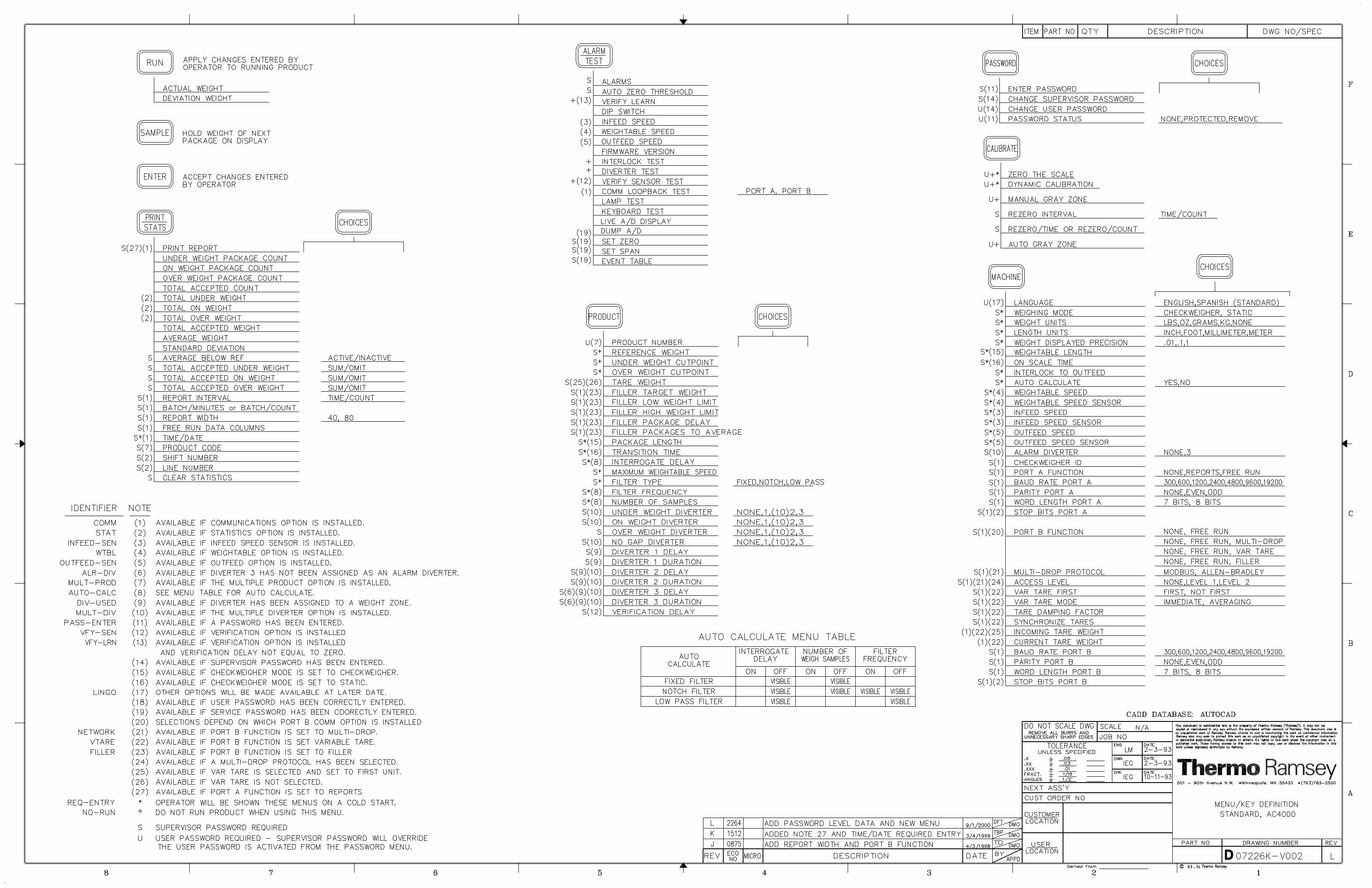
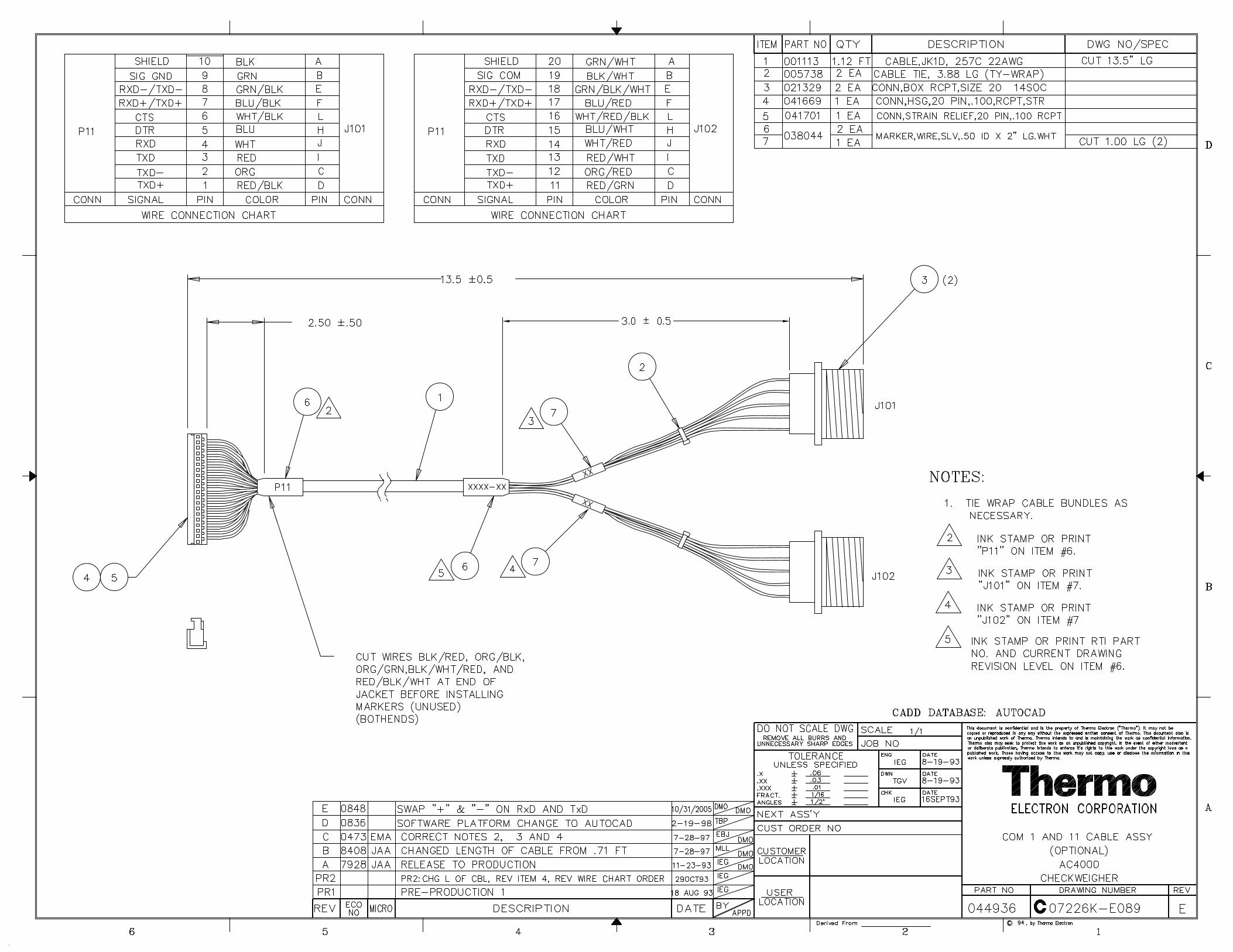
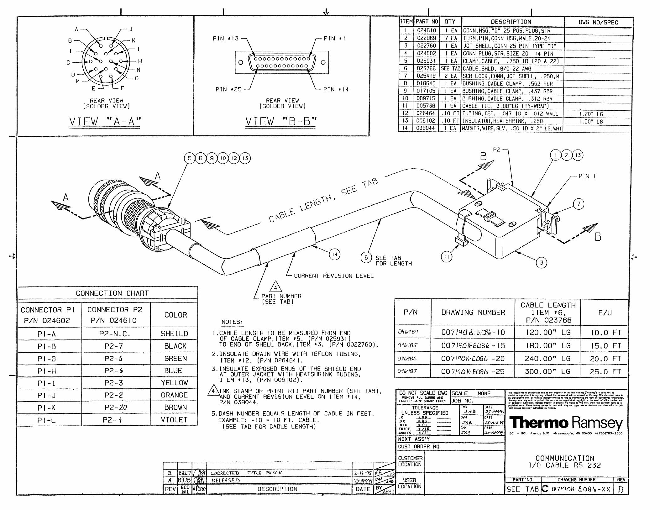
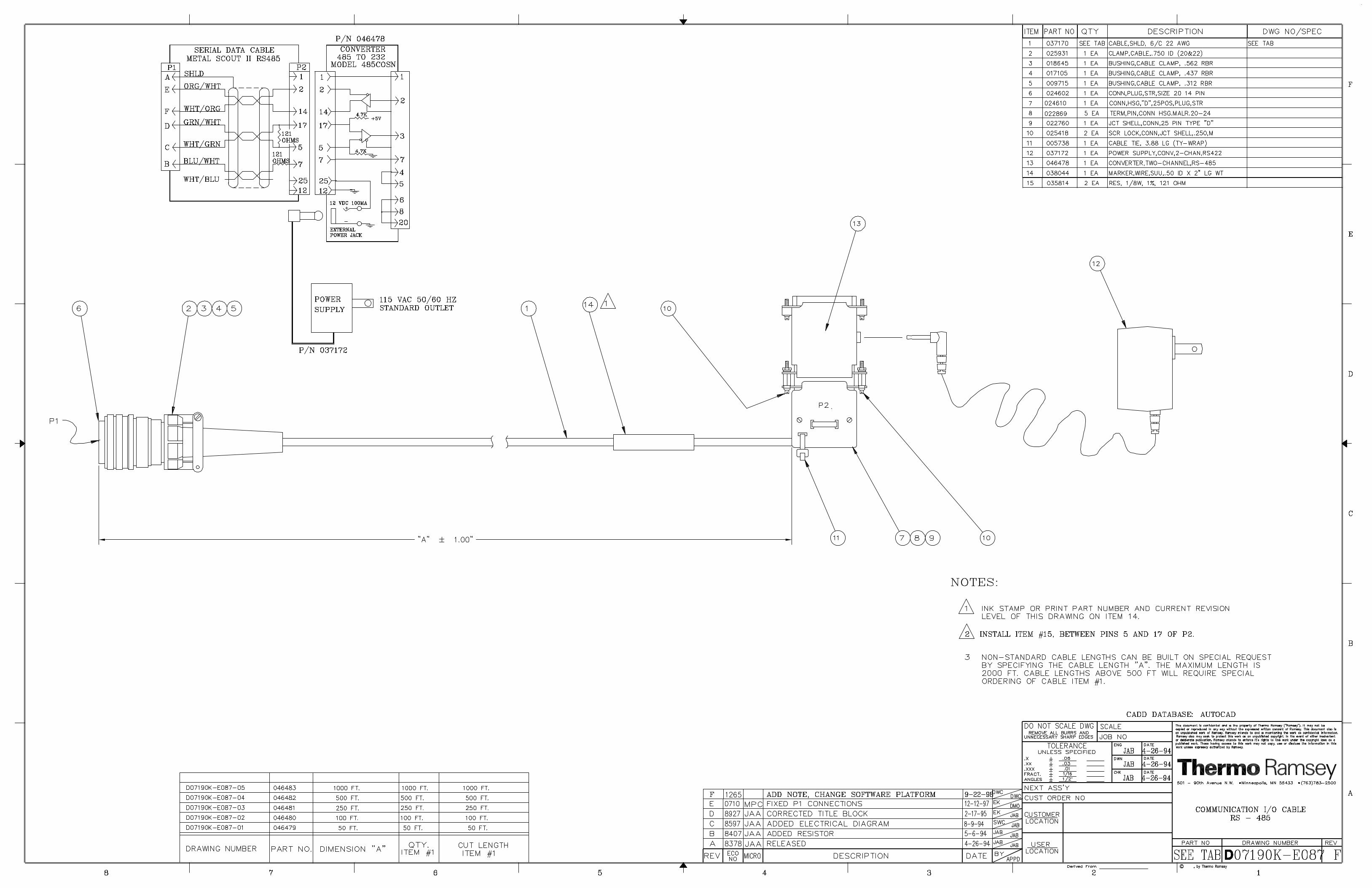
A/1 Field Wiring Diagram Engineer SelectedA/3 Full Menu Tree D07226K-V002A/5 Comm I/Comm II Cable Assembly C07226K-E089A/6 Comm I/O Cable EIA-232 C07190K-E086A/7 Comm I/O Cable EIA-485 D07190K-E087
SUPPLEMENTAL MANUALS
TITLE DOCUMENT NO.
Minarik Adjustable Speed Control, Model MM 2300 MC-3

REC 3829 VIII
PREFACE
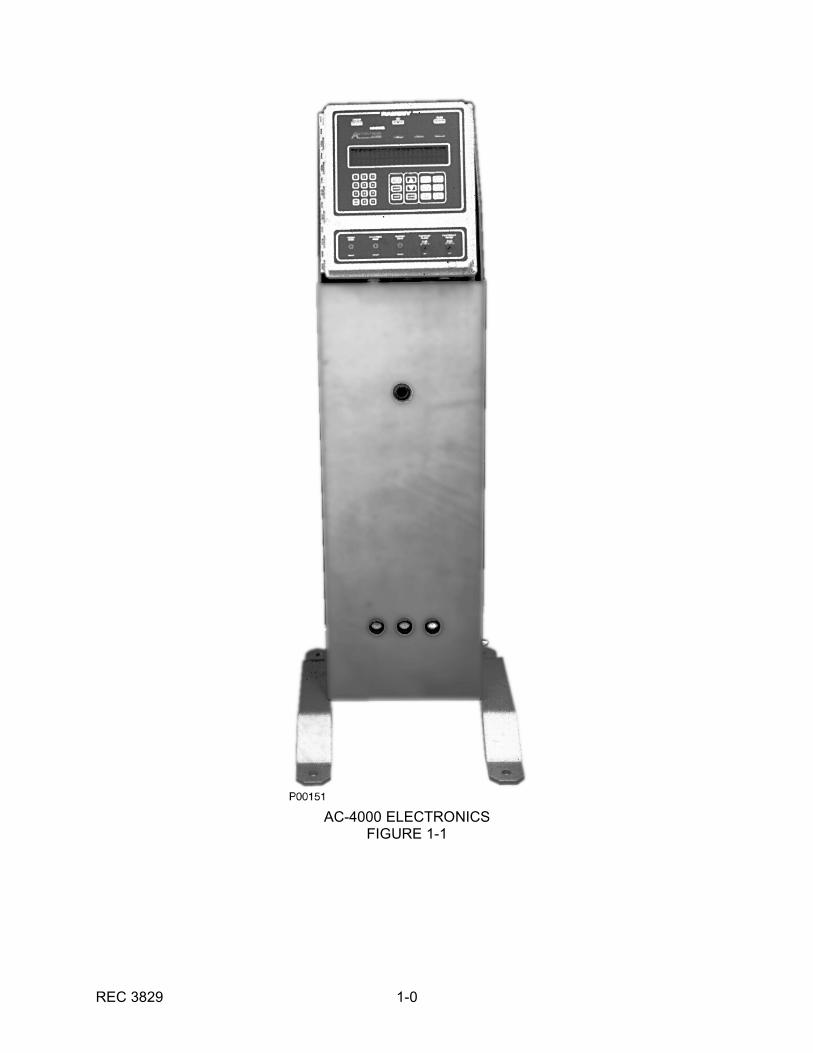
This manual contains information necessary to install, operate, and service the Thermo AC-4000 Electronics (see Figure 1-1).
All persons concerned with the operation and servicing of the electronics should read thecontents of this manual carefully and thoroughly. Keep this manual in a convenient place andrefer to it often, as it is an important tool in performing proper service.
Information in this manual is presented as follows:
Chapter 1.0, INTRODUCTION, presents a brief description of the electronics' capabilities,operation, features, options specifications and warranty.
Chapter 2.0, INSTALLATION, outlines site preparation operating requirements, and installationinstructions.
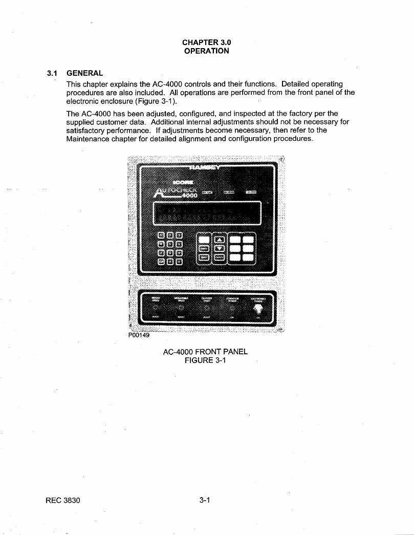
Chapter 3.0, OPERATION, explains the operating controls and procedures.
Chapter 4.0, MAINTENANCE, includes troubleshooting, electronic checkout, and maintenanceprocedures.
Chapter 5.0, REPLACEMENT PARTS, provides ordering information and replaceable parts list.
Chapter 6.0, OPTIONS, contains information about optional equipment.
The APPENDIX contains assembly, installation, and wiring drawings.
IMPORTANT
Do not turn the equipment on or attempt to operate the electronics until you have read andunderstood Chapters 2.0 and 3.0. Improper operation of the electronics may result in damageto the machine.
REC 3829 1-0
AC-4000 ELECTRONICSFIGURE 1-1
REC 3829 1-1
CHAPTER 1.0INTRODUCTION
1.1 GENERAL DESCRIPTION
The AC-4000 Electronics System is a high accuracy machine. When combined with aweighing frame, it performs weight inspection of individual product packages in aproduction process or package line. The AC-4000 and a weighing frame perform thesefunctions without interrupting product flow.
1.1.1 Applications
Typical applications for the AC-4000 Electronics System are the in-motionweighing of:
Frozen food, bakery, confectionery, meat, and any canned or packaged goods.
Detergents, chemicals, pharmaceutical, and any bottled liquid products.
Manufactured products such as rubber, plastic, metal parts, multi-component partspackages, and count-by-weight packages.
1.1.2 System Description
The AC-4000 Electronics System consists of:
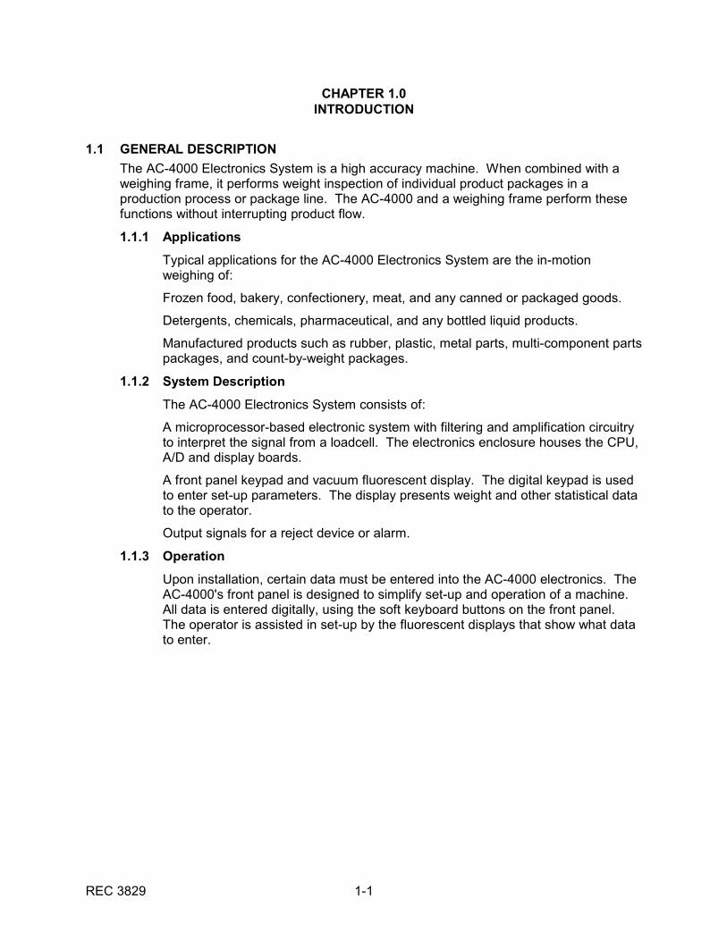
A microprocessor-based electronic system with filtering and amplification circuitryto interpret the signal from a loadcell. The electronics enclosure houses the CPU,A/D and display boards.
A front panel keypad and vacuum fluorescent display. The digital keypad is usedto enter set-up parameters. The display presents weight and other statistical datato the operator.
Output signals for a reject device or alarm.
1.1.3 Operation
Upon installation, certain data must be entered into the AC-4000 electronics. TheAC-4000's front panel is designed to simplify set-up and operation of a machine. All data is entered digitally, using the soft keyboard buttons on the front panel. The operator is assisted in set-up by the fluorescent displays that show what datato enter.
REC 3829 1-2
SYSTEM BLOCK DIAGRAMFIGURE 1-2
REC 3829 1-3
During operation, the package is transported by a conveying medium (such aschains or belts) across a weightable. The loadcell supporting a weightableproduces an electronic signal proportional to the package weight. As the packageinterrupts a beam from a photocell sensor (interlock), the gross weight of thepackage is computed by the AC-4000 electronics. This weight is then comparedto the setpoint zone settings to determine the appropriate zone. A reject devicemay then be activated for off-weight packages.
The AC-4000 will display the weight class (zone) of the last package weighed, aswell as the actual weight of the package in grams, kilograms, ounces or pounds. Using the front panel keyboard, the AC-4000 also will display the total number ofpackages in each weigh zone and the average weight of the packages in eachzone.
1.1.4 Features
The AC-4000 Electronics System has the following standard features:
1. Auto Zero and Manual Zero
The electronics automatically compensate for minor buildup on the weightableby rezeroing the weightable between packages. Manual zero allows therezeroing of the weightable at the operator's discretion.
2. Automatic Self-Diagnostics
This feature continually monitors system operation and assures thateverything is operating properly. A fault relay for connection to an externalalarm is provided.
3. Digital Filter Setup
During set-up, filter parameters are selected for individual products using thefront panel keyboard. This exclusive feature improves the weighing accuracyby providing the best filter setting for each product.
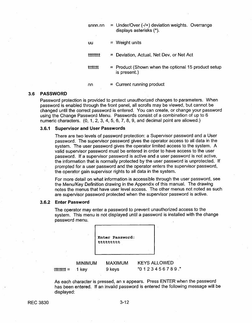
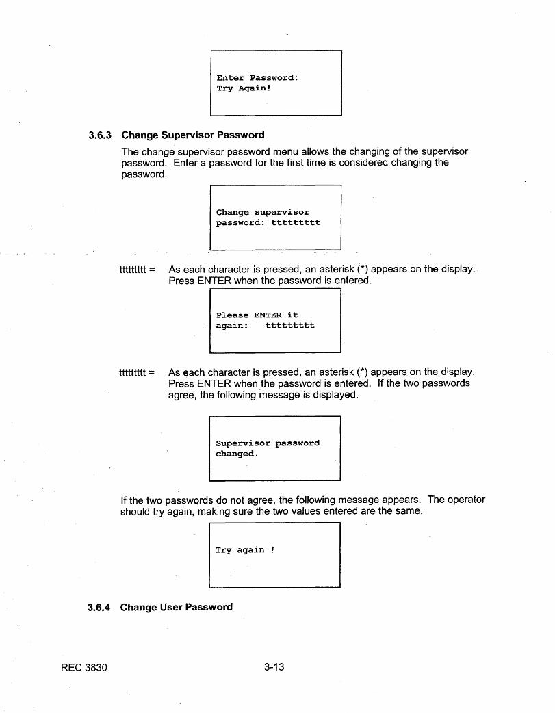
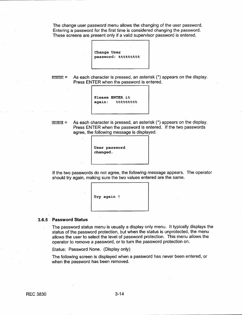
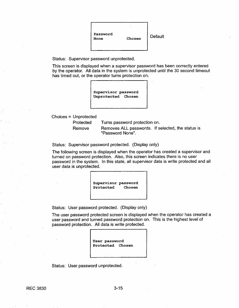
4. Password Protection
This feature provides protection against an unauthorized change in set-upparameters and access to certain data.
5. Permanent Data Storage
An EEPROM retains set-up information and stores accumulated data.
6. 32-Bit Microprocessor
This large memory capacity increases the flexibility of the AC-4000 and allowsit to handle a broader range of applications.
7. Corrosion Resistant Finish
All exposed metal parts on the AC-4000 Electronics System are eitherstainless steel or painted mild steel.

REC 3829 1-4
1.2 OPTIONS
Electronics can be remote or local, and numerous options are available to transform theAC-4000 from a low-cost, basic electronics into a sophisticated tool for monitoringproductivity and packaging line performance. These options include the following:
1.2.1 15 Programmable Product Set-Ups
The set-up parameters for 15 products can be preset into the electronics. TheAC-4000 can then be switched from one product to another in a matter ofseconds.
1.2.2 Statistics (STATS)
The Statistics option provides statistical information on package weights.
1.2.3 Multiple Diverter
The Multiple Diverter option provides for three diverter outputs. The package canbe diverted into under-weight, on-weight and over-weight categories if desired. Also can be used for No Gaps (package spacing is too close) or as an alarmactuator to signal remote locations of alarm status.
1.2.4 Diverter Verification
The Diverter Verification option provides verification that packages are properlydiverted. It generates an alarm if a package which should have been diverted isseen, or if one which should not have been diverted is not seen.
1.2.5 Communications (COM)
The Communication option provides for communication of weight or statisticalinformation from the AC-4000 to a printer, CRT, or host computer. Theinformation can be in the form of raw weight data or a formatted report, dependingupon the STATS option included with the electronics.
Other optional communications capabilities are also available.
REC 3829 1-5
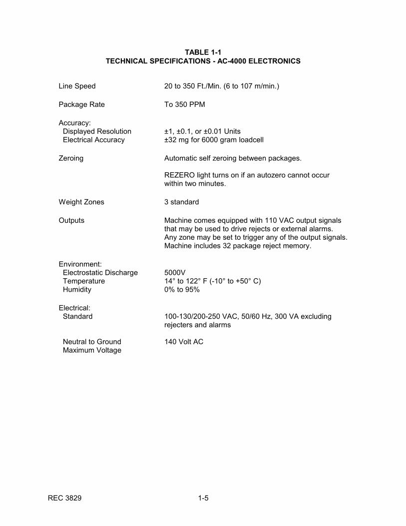
TABLE 1-1TECHNICAL SPECIFICATIONS - AC-4000 ELECTRONICS
Line Speed 20 to 350 Ft./Min. (6 to 107 m/min.)
Package Rate To 350 PPM
Accuracy: Displayed Resolution Electrical Accuracy
±1, ±0.1, or ±0.01 Units±32 mg for 6000 gram loadcell
Zeroing Automatic self zeroing between packages.
REZERO light turns on if an autozero cannot occurwithin two minutes.
Weight Zones 3 standard
Outputs Machine comes equipped with 110 VAC output signalsthat may be used to drive rejects or external alarms. Any zone may be set to trigger any of the output signals. Machine includes 32 package reject memory.
Environment: Electrostatic Discharge Temperature Humidity
5000V14° to 122° F (-10° to +50° C)0% to 95%
Electrical: Standard
Neutral to Ground Maximum Voltage
100-130/200-250 VAC, 50/60 Hz, 300 VA excludingrejecters and alarms
140 Volt AC
REC 3829 1-6
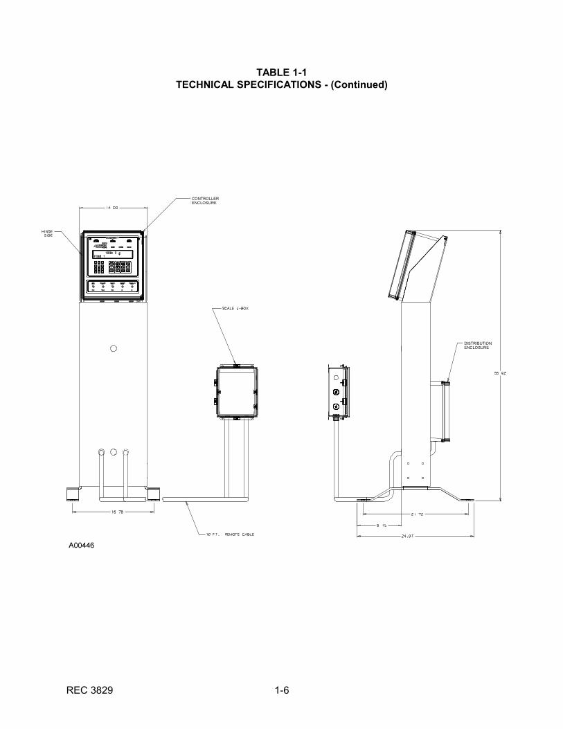
TABLE 1-1TECHNICAL SPECIFICATIONS - (Continued)

REC 3829 1-7
1.3 WARRANTY
THERMO ELECTRON
WARRANTY
The seller agrees, represents, and warrants that the equipment delivered hereunder shall be freefrom defects in material and workmanship. Such warranty shall not apply to accessories, parts,or material purchased by the seller unless they are manufactured pursuant to seller's design, butshall apply to the workmanship incorporated in the installation of such items in the completeequipment. To the extent purchased parts or accessories are covered by the manufacturer'swarranty, seller shall extend such warranty to buyer.
Seller's obligation under said warranty is conditioned upon the return of the defective equipment,transportation charges prepaid, to the seller's factory in Minneapolis, Minnesota, and thesubmission of reasonable proof to seller prior to return of the equipment that the defect is due toa matter embraced within seller's warranty hereunder. Any such defect in material andworkmanship shall be presented to seller as soon as such alleged errors or defects are discoveredby purchaser and seller is given opportunity to investigate and correct alleged errors or defects andin all cases, buyer must have notified seller thereof within one (1) year after delivery, or one (1)year after installation if the installation was accomplished by the seller.
Said warranty shall not apply if the equipment shall not have been operated and maintained inaccordance with seller's written instructions applicable to such equipment, or if such equipmentshall have been repaired or altered or modified without seller's approval; provided, however, thatthe foregoing limitation of warranty insofar as it relates to repairs, alterations, or modifications, shallnot be applicable to routine preventive and corrective maintenance which normally occur in theoperation of the equipment.
"EXCEPT FOR THOSE WARRANTIES SPECIFICALLY CONTAINED HEREIN, SELLERDISCLAIMS ANY AND ALL WARRANTIES WITH RESPECT TO THE EQUIPMENT DELIVEREDHEREUNDER, INCLUDING THE IMPLIED WARRANTIES OF MERCHANTABILITY ANDFITNESS FOR USE. THE SOLE LIABILITY OF SELLER ARISING OUT OF THE WARRANTYCONTAINED HEREIN SHALL BE EXCLUSIVELY LIMITED TO BREACH OF THOSEWARRANTIES. THE SOLE AND EXCLUSIVE REMEDY FOR BREACH OF THE WARRANTIESSET OUT ABOVE SHALL BE LIMITED TO THE REPAIR OR REPLACEMENT OF ANYDEFECTIVE ACCESSORY, PART OR MATERIAL WITH A SIMILAR ITEM FREE FROM DEFECT,AND THE CORRECTION OF ANY DEFECT IN WORKMANSHIP. IN NO EVENT SHALL SELLERBE LIABLE FOR ANY INCIDENTAL OR CONSEQUENTIAL DAMAGES."
FIELD SERVICE
Purchaser agrees to underwrite the cost of any labor required for replacement; including time,travel, and living expenses of Thermo Ramsey Field Service Engineer at closest factory base.
THERMO ELECTRON501 90th Avenue N.W.Minneapolis, MN 55433Phone: (763) 783-2500Fax: (763) 783-2525

REC 3829 2-1
CHAPTER 2.0INSTALLATION
2.1 GENERAL
The customer is responsible for initial inspection of the equipment and site preparation. Itis essential that the equipment be placed on the production line in accordance with theguidelines set forth in this section. The customer must ensure that qualified personnel areavailable to make interconnections with other production equipment and perform work atthe installation site. A Thermo Customer Service representative is available to superviseinstallation and verify operation as well as train personnel assigned to operate andmaintain the equipment.
2.2 SAFETY PRECAUTIONS
IMPORTANT Do not install, operate, or perform any maintenance procedures until you have read thesafety precautions presented below.
1. Do not connect power to the machine or turn on the unit until you have read andunderstood this entire manual. The precautions and procedures presented in thismanual must be followed carefully in order to prevent equipment damage andprotect the operator from possible injury.
2. CAUTION! Hands and clothing must be kept away from all moving or rotatingparts.
3. WARNING! Covers over the electronics, or rotating parts should always remain inplace during operation. They should be removed only for maintenance procedureswith the machine's power OFF. Be sure to replace all covers before resumingoperation.
4. WARNING! All switches (control, motor, power, etc., as applicable) must be OFFwhen checking input AC electrical connections, removing or inserting printed circuitboards, or attaching voltmeters to the system.
5. Incoming voltages must be checked with a voltmeter before being connected to themachine. Pay special attention to the red tag attached to the machine thatstipulates the correct input voltage for your particular unit.
6. WARNING! Extreme caution must be used in testing in, on, or around theelectronics cabinet, PC boards, or modules. There are voltages in excess of 115V,230V, or 440V in these areas. Avoid high voltage and static electricity around theprinted circuit board.
7. CAUTION! Do not leave insulating material over the machine for any length of timeor the machine will overheat. The specified maximum ambient temperature is not tobe exceeded for more than 5 minutes.
8. Maintenance procedures should be performed only by qualified personnel and inaccordance with procedures/instructions given in this manual.
9. During maintenance, a safety tag (not supplied by Thermo) should be displayed inthe ON/OFF switch areas as a precaution instructing others not to operate the unit(ANSI:B157.1).
10. Only qualified electricians should be allowed to open and work in the electronicscabinets, power supply cabinets, control cabinets, or switch boxes.

REC 3829 2-2
11. Objects of any kind should never be placed or stored on the machine.
12. This equipment should not be operated at more than the specified production ratenor utilized in applications other than those stated in the original order. (To adaptproduction rates or applications, consult Thermo Products Customer Service forrecommendations.)
13. All panels and doors covering the electronics must be in place and tight beforeconducting wash down. Damage to the electronics could result from water,moisture, or contamination in the electronics housing.
14. Harsh chemicals, caustics, disinfectants, etc., should never be added to wash downsolutions.
15. Indeed and outfield conveyors and transfer assemblies should be mounted and/orpositioned so clearance is maintained between moving parts. Check to ensureweighing or infeed/outfield conveyor(s) are clear of debris before turning the drivemotor ON.
2.2.1 Occupational Safety and Health Act (OSHA)
The Occupational Safety and Health Act clearly places the burden of complianceon the user of the equipment and the act is generalized to the extent thatdetermination of compliance is a judgement decision on the part of the localinspection. Hence Thermo Ramsey will not be responsible for meeting the fullrequirements of OSHA in respect to the equipment supplied or for any penaltyassessed for failure to meet the requirements, in respect to the equipmentsupplied, of the Occupational Safety and Health Act, as interpreted by anauthorized inspector. Thermo Ramsey will use their best efforts to remedy suchviolation at a reasonable cost to the buyer.
2.3 STORAGE
If you are not going to install the electronics system now, it can be safely stored attemperatures from -40° F (-40° C) to +158° F (+70° C). All components should beprotected against moisture.
2.4 UNCRATING & INSPECTION
The electronics system has been properly packaged for shipment. Inspect all packagesfor damage before opening as often times the carrier may be responsible for shippingdamage.
1. Inspect the electronics for shipping damage.
2. Remove the poly covering from the electronics.
3. Cut the nylon shipping bands securing the electronics to pallet.
4. Lift the electronics and pedestal off the pallet.

REC 3829 2-3
2.5 EQUIPMENT LOCATION
Careful consideration should be given to the location of the electronics, as systemperformance is affected by its location. The following requirements must be followed.
1. The electronics should be located so maintenance personnel can easily performcleaning and adjustment procedures, and so both the control panel and electronicsenclosure rear doors are easily accessible. This requires clear space behind and infront of the machine.
2. There should be a minimum of vibration in the area. Vibrations can be conducted toa loadcell and affect weighing accuracy.
3. The electronics system is designed to operate in an environment where thetemperature ranges no lower than -14° F (-10° C) nor higher than 122° F (50° C).
4. The electronics will operate in an environment where the humidity (non-condensing)ranges from 0% to 95%.
REC 3829 2-4
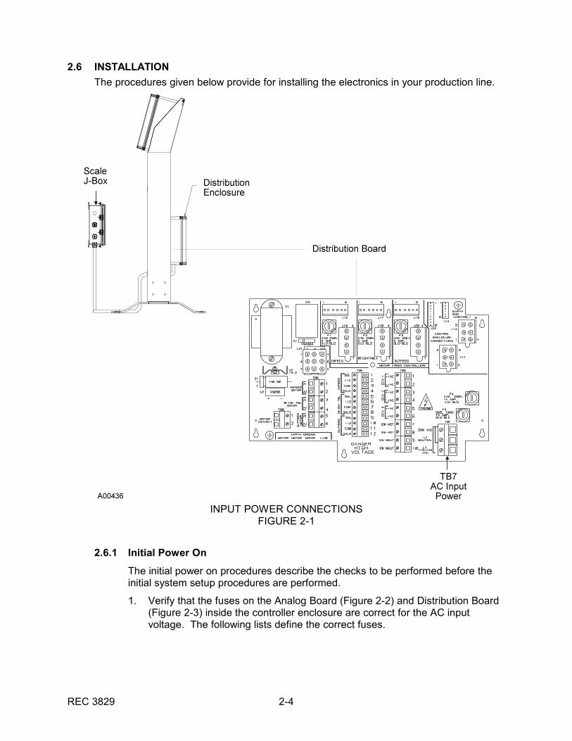
INPUT POWER CONNECTIONSFIGURE 2-1
2.6 INSTALLATION
The procedures given below provide for installing the electronics in your production line.
2.6.1 Initial Power On
The initial power on procedures describe the checks to be performed before theinitial system setup procedures are performed.
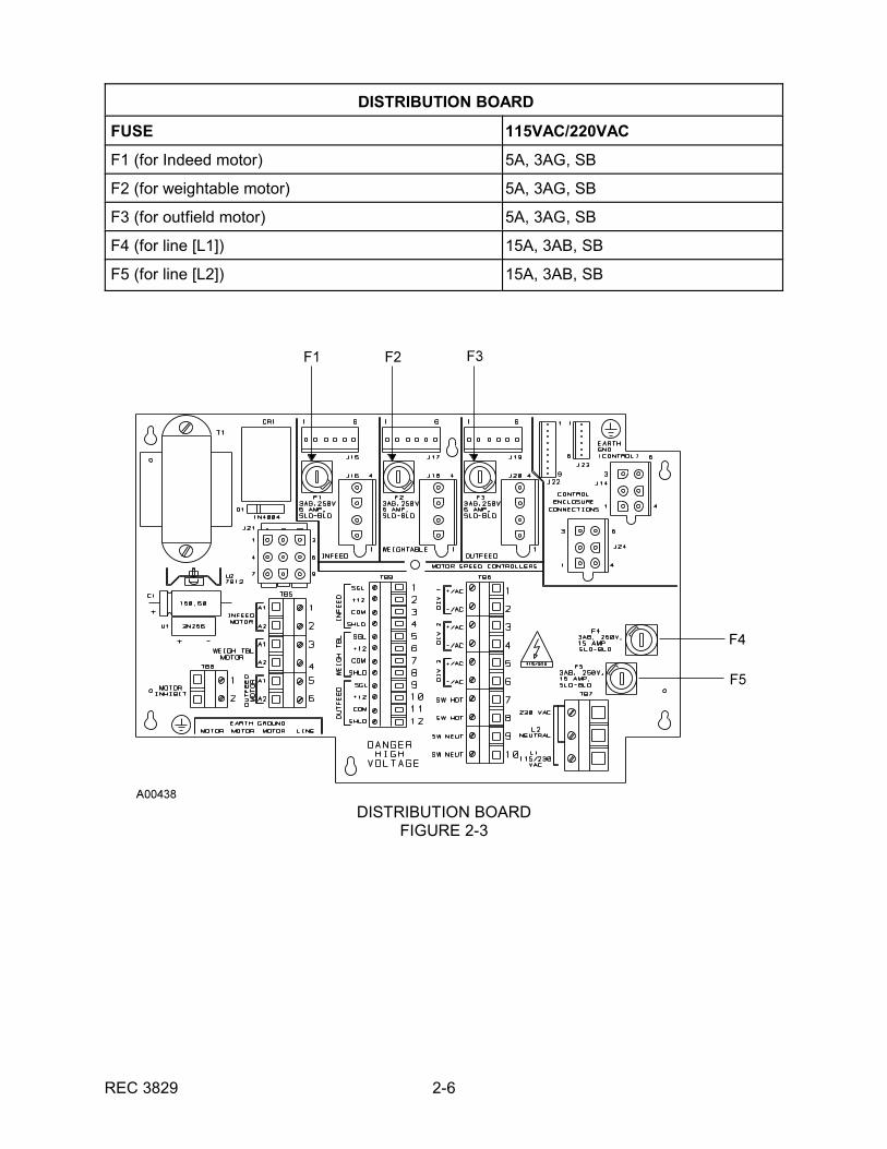
1. Verify that the fuses on the Analog Board (Figure 2-2) and Distribution Board(Figure 2-3) inside the controller enclosure are correct for the AC inputvoltage. The following lists define the correct fuses.
REC 3829 2-5
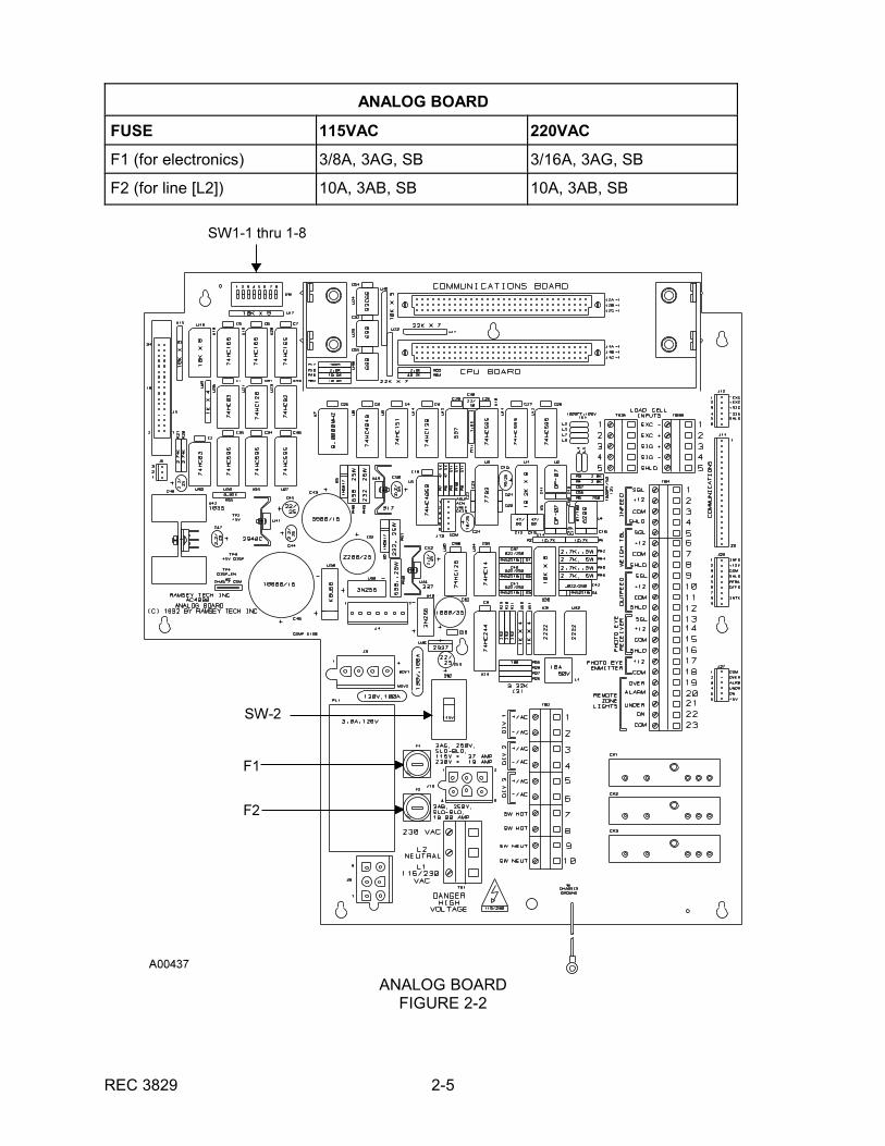
ANALOG BOARDFIGURE 2-2
ANALOG BOARD
FUSE 115VAC 220VAC
F1 (for electronics) 3/8A, 3AG, SB 3/16A, 3AG, SB
F2 (for line [L2]) 10A, 3AB, SB 10A, 3AB, SB
REC 3829 2-6
DISTRIBUTION BOARDFIGURE 2-3
DISTRIBUTION BOARD
FUSE 115VAC/220VAC
F1 (for Indeed motor) 5A, 3AG, SB
F2 (for weightable motor) 5A, 3AG, SB
F3 (for outfield motor) 5A, 3AG, SB
F4 (for line [L1]) 15A, 3AB, SB
F5 (for line [L2]) 15A, 3AB, SB
REC 3829 2-7
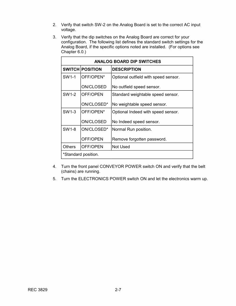
2. Verify that switch SW-2 on the Analog Board is set to the correct AC inputvoltage.
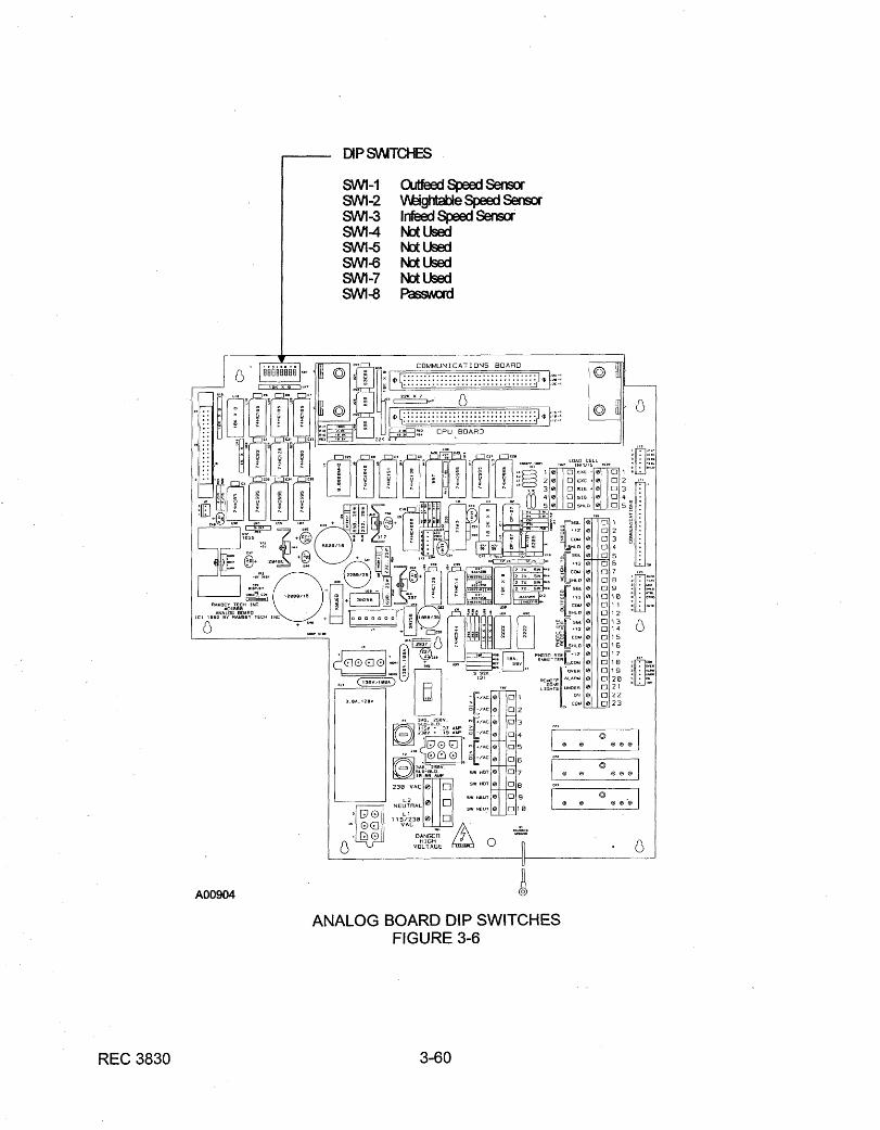
3. Verify that the dip switches on the Analog Board are correct for yourconfiguration. The following list defines the standard switch settings for theAnalog Board, if the specific options noted are installed. (For options seeChapter 6.0.)
ANALOG BOARD DIP SWITCHES
SWITCH POSITION DESCRIPTION
SW1-1 OFF/OPEN*
ON/CLOSED
Optional outfield with speed sensor.
No outfield speed sensor.
SW1-2 OFF/OPEN
ON/CLOSED*
Standard weightable speed sensor.
No weightable speed sensor.
SW1-3 OFF/OPEN*
ON/CLOSED
Optional Indeed with speed sensor.
No Indeed speed sensor.
SW1-8 ON/CLOSED*
OFF/OPEN
Normal Run position.
Remove forgotten password.
Others OFF/OPEN Not Used
*Standard position.
4. Turn the front panel CONVEYOR POWER switch ON and verify that the belt(chains) are running.
5. Turn the ELECTRONICS POWER switch ON and let the electronics warm up.

This page intentionally left blank


This page intentionally left blank


This page intentionally left blank


This page intentionally left blank


REC 3829 4-0

This page intentionally left blank
REC 3829 4-1
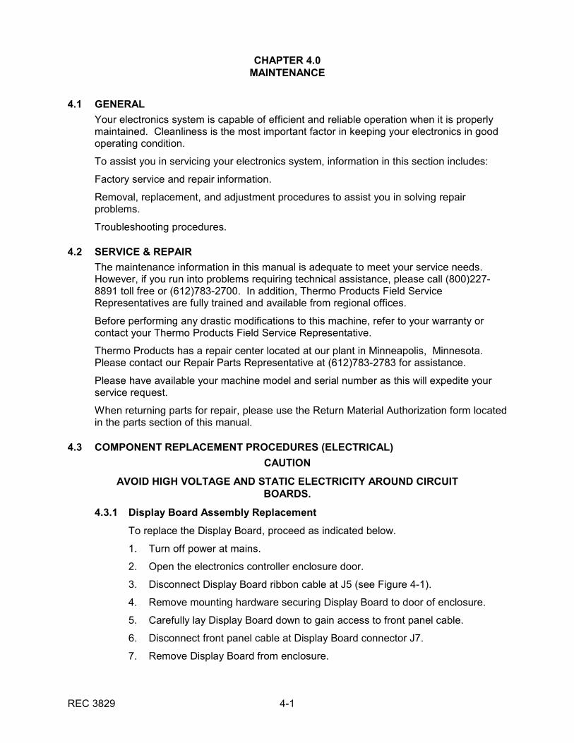
CHAPTER 4.0MAINTENANCE
4.1 GENERAL
Your electronics system is capable of efficient and reliable operation when it is properlymaintained. Cleanliness is the most important factor in keeping your electronics in goodoperating condition.
To assist you in servicing your electronics system, information in this section includes:
Factory service and repair information.
Removal, replacement, and adjustment procedures to assist you in solving repairproblems.
Troubleshooting procedures.
4.2 SERVICE & REPAIR
The maintenance information in this manual is adequate to meet your service needs. However, if you run into problems requiring technical assistance, please call (800)227-8891 toll free or (612)783-2700. In addition, Thermo Products Field ServiceRepresentatives are fully trained and available from regional offices.
Before performing any drastic modifications to this machine, refer to your warranty orcontact your Thermo Products Field Service Representative.
Thermo Products has a repair center located at our plant in Minneapolis, Minnesota. Please contact our Repair Parts Representative at (612)783-2783 for assistance.
Please have available your machine model and serial number as this will expedite yourservice request.
When returning parts for repair, please use the Return Material Authorization form locatedin the parts section of this manual.
4.3 COMPONENT REPLACEMENT PROCEDURES (ELECTRICAL)
CAUTION
AVOID HIGH VOLTAGE AND STATIC ELECTRICITY AROUND CIRCUITBOARDS.
4.3.1 Display Board Assembly Replacement
To replace the Display Board, proceed as indicated below.
1. Turn off power at mains.
2. Open the electronics controller enclosure door.
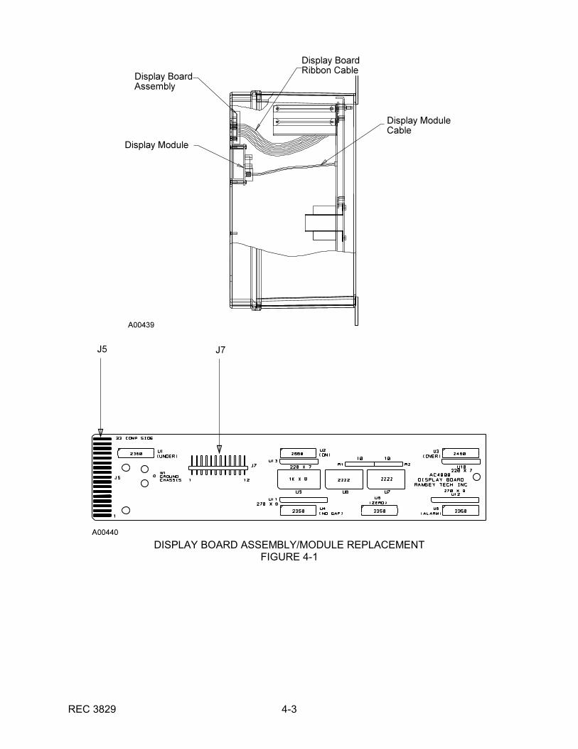
3. Disconnect Display Board ribbon cable at J5 (see Figure 4-1).
4. Remove mounting hardware securing Display Board to door of enclosure.
5. Carefully lay Display Board down to gain access to front panel cable.
6. Disconnect front panel cable at Display Board connector J7.
7. Remove Display Board from enclosure.
REC 3829 4-2
8. Place new Display Board in enclosure with Display Board ribbon cable towardthe enclosure hinge.
9. Connect front panel cable to Display Board connector J7.
10. Install new Display Board on mounting bolts.
11. Replace mounting hardware securing board to enclosure.
12. Connect Display Board ribbon cable to Display Board connector J7.
13. Close electronics controller enclosure door.
14. Apply power to electronics and verify proper operation.
4.3.2 Display Module Replacement
To replace the Display Module, proceed as indicated below.
1. Turn off power at mains.
2. Open the electronics controller enclosure door.
3. Remove the Display Module cable (see Figure 4-1).
4. Remove mounting hardware securing Display Module to enclosure.
5. Remove Module and place the new one on the four threaded studs.
6. Replace the mounting hardware and reconnect the Display Module cable.
7. Close and secure the electronics controller enclosure door.
8. Apply power to electronics and verify proper operation.
4.3.3 Communication Board Replacement
To replace the Communication Board, proceed as indicated below.
1. Turn off power at mains.
2. Open electronics controller enclosure door.
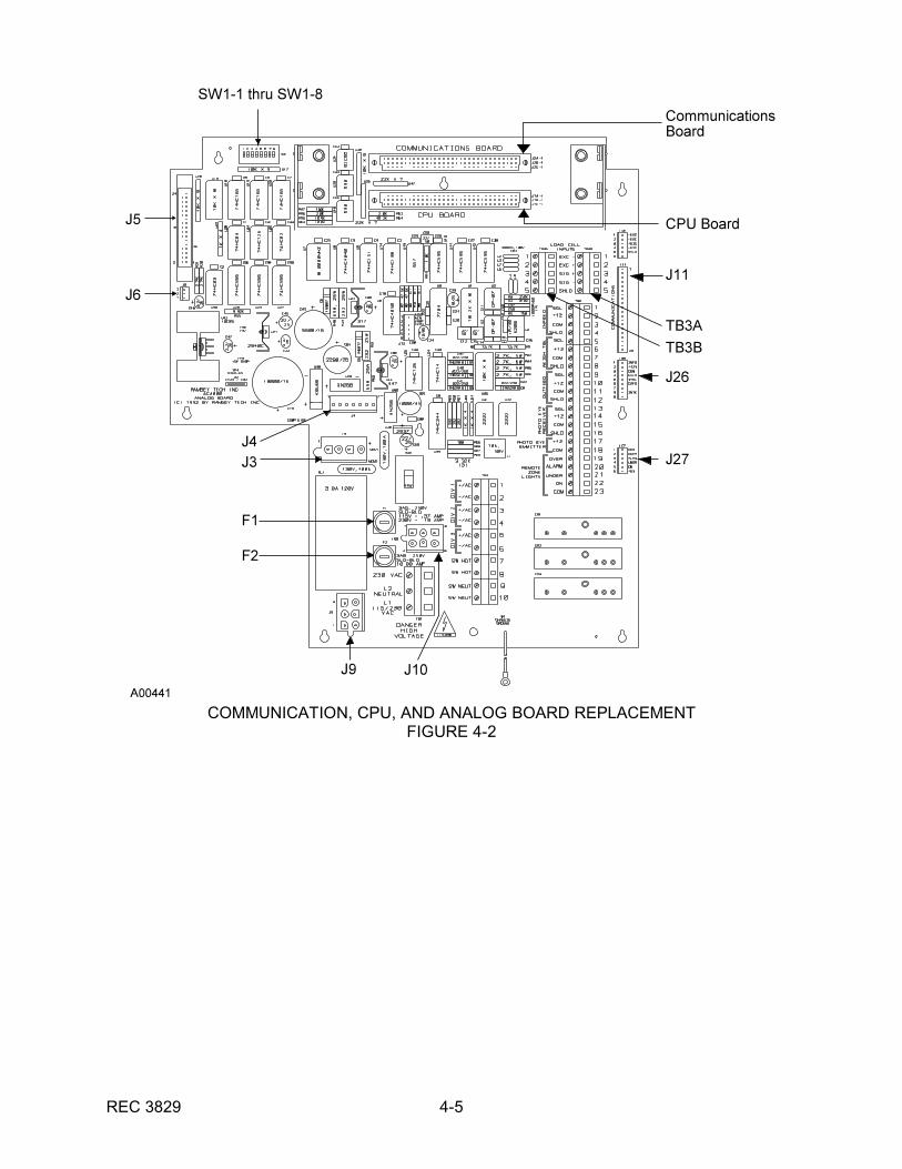
3. Locate the Communication Board (directly above the CPU Board) near theupper, back portion of the enclosure (see Figure 4-2).
4. Gently pull the Communication Board handle, extracting the board from thepin connectors.
5. Place new Communication Board in enclosure. Insure the board is in theupper slot, properly oriented and fully seated.
6. Set all switches on new Communication Board as they were positioned on oldboard.
7. Verify all setups. Refer to Chapter 3 of this manual for setup procedures.
REC 3829 4-3
DISPLAY BOARD ASSEMBLY/MODULE REPLACEMENTFIGURE 4-1
REC 3829 4-4
4.3.4 CPU Board Replacement
To replace the CPU Board, proceed as indicated below.
NOTE: If your electronics system is operating erratically, try to capture as muchsetup data as possible before turning off power.
1. Turn off power at mains.
2. Open electronics controller enclosure door.
3. Locate the CPU Board (directly below the Communication Board) near theupper, back portion of the enclosure (see Figure 4-2).
4. Remove hardware securing CPU board. Gently pull the CPU card handle,extracting the board from the pin connectors.
5. Place new CPU Board in enclosure. Insure the board is in the lower slot,properly oriented and fully seated.
6. Perform a Cold Start Procedure.
7. Verify all setups. Refer to Chapter 3 for all setup procedures.
4.3.5 Analog Board Replacement
To replace the Analog Board, proceed as indicated below.
1. Turn off power at mains.
2. Open electronic controller enclosure door.
3. Disconnect Analog Board cables J3, J4, J5, J6, J9, J10, J11, J26, and (seeFigure 4-2).
4. Unscrew loadcell cables at TB3A and TB3B. Also unscrew all wires on TB4.
5. Remove screw and washer securing Analog Board to enclosure.
6. Remove Analog Board from enclosure.
7. Verify DIP Switch SW1-1 through SW1-8 settings on new Analog Board withold board.
8. Verify fuses.
9. Remove CPU Board and optional Communication Board from old AnalogBoard and place in the new Analog Board. Verify that the boards are in theirproper slots and are fully seated.
10. Place new Analog Board in enclosure.
11. Secure new Analog Board to enclosure.
12. Reconnect loadcell cables to Analog Board, and reconnect wires to TB4.
13. Connect Analog Board cables J3 and J4 to CPU Board connectors J3, J4, J5,J6, J9, J10, J11, J26, and J27.
14. Perform a Cold Start Procedure.
15. Apply power to electronics and recalibrate machine. Refer to Chapter 3 forcalibration procedures.
REC 3829 4-5
COMMUNICATION, CPU, AND ANALOG BOARD REPLACEMENTFIGURE 4-2
REC 3829 4-6
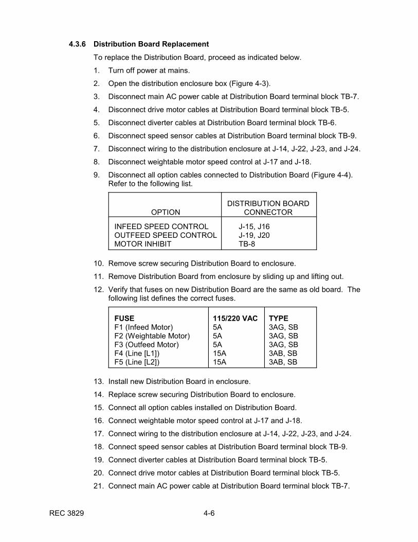
4.3.6 Distribution Board Replacement
To replace the Distribution Board, proceed as indicated below.
1. Turn off power at mains.
2. Open the distribution enclosure box (Figure 4-3).
3. Disconnect main AC power cable at Distribution Board terminal block TB-7.
4. Disconnect drive motor cables at Distribution Board terminal block TB-5.
5. Disconnect diverter cables at Distribution Board terminal block TB-6.
6. Disconnect speed sensor cables at Distribution Board terminal block TB-9.
7. Disconnect wiring to the distribution enclosure at J-14, J-22, J-23, and J-24.
8. Disconnect weightable motor speed control at J-17 and J-18.
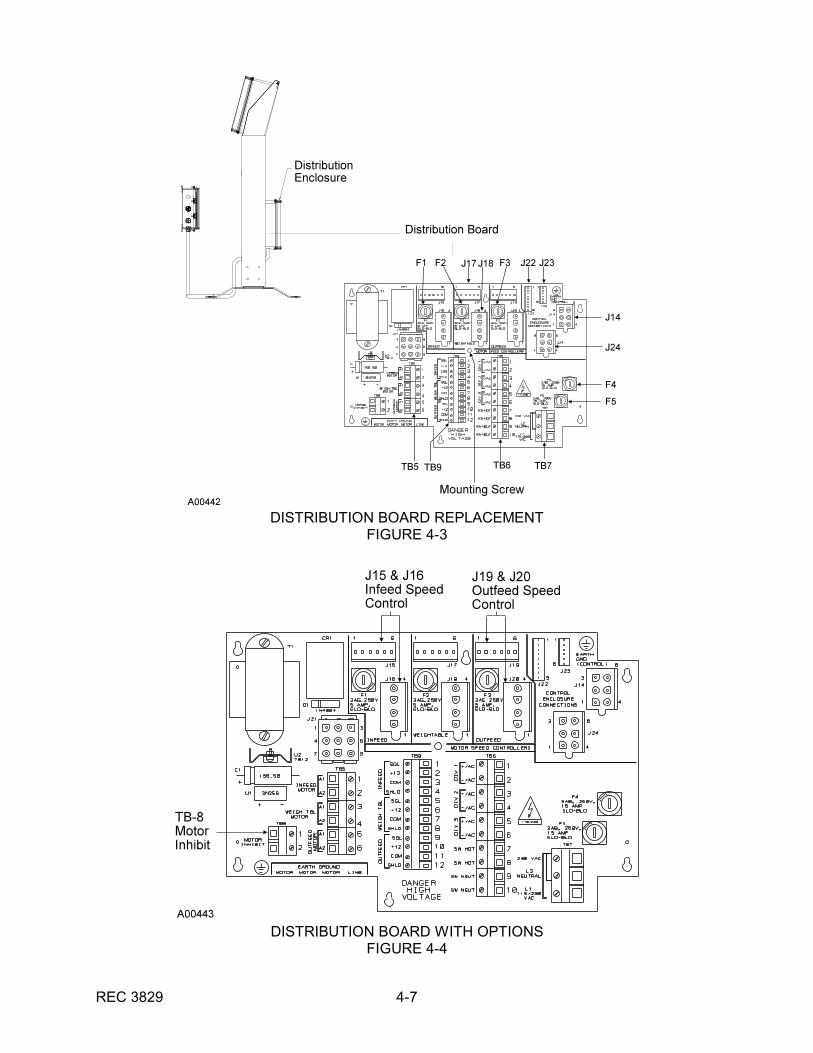
9. Disconnect all option cables connected to Distribution Board (Figure 4-4). Refer to the following list.
OPTIONDISTRIBUTION BOARD
CONNECTOR
INFEED SPEED CONTROLOUTFEED SPEED CONTROLMOTOR INHIBIT
J-15, J16 J-19, J20 TB-8
10. Remove screw securing Distribution Board to enclosure.
11. Remove Distribution Board from enclosure by sliding up and lifting out.
12. Verify that fuses on new Distribution Board are the same as old board. Thefollowing list defines the correct fuses.
FUSEF1 (Infeed Motor)F2 (Weightable Motor)F3 (Outfeed Motor)F4 (Line [L1])F5 (Line [L2])
115/220 VAC5A5A5A15A15A
TYPE3AG, SB3AG, SB3AG, SB3AB, SB3AB, SB
13. Install new Distribution Board in enclosure.
14. Replace screw securing Distribution Board to enclosure.
15. Connect all option cables installed on Distribution Board.
16. Connect weightable motor speed control at J-17 and J-18.
17. Connect wiring to the distribution enclosure at J-14, J-22, J-23, and J-24.
18. Connect speed sensor cables at Distribution Board terminal block TB-9.
19. Connect diverter cables at Distribution Board terminal block TB-5.
20. Connect drive motor cables at Distribution Board terminal block TB-5.
21. Connect main AC power cable at Distribution Board terminal block TB-7.
REC 3829 4-7
DISTRIBUTION BOARD REPLACEMENTFIGURE 4-3
DISTRIBUTION BOARD WITH OPTIONSFIGURE 4-4

REC 3829 4-8
22. Close the distribution enclosure box.
23. Apply power to electronics and verify proper operation.
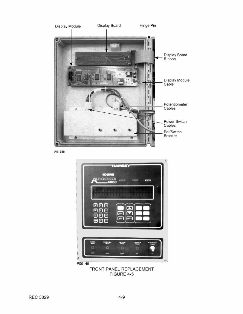
4.3.7 Front Panel Replacement
To replace the controller front panel door, proceed as indicated below.
Fiberglass Enclosure
1. Turn off power at mains.
2. Disconnect the cables (display board, display module ribbon, and pot/switch)attached to the front door (see Figure 4-5).
3. Using a drive pin, force the hinge pin up from the bottom until it can begrasped with a pliers and removed from the controller enclosure door.
4. Remove the front panel door.
5. Remove the display board and display module from inside the front paneldoor.
6. Remove the nut(s) securing any externally mounted potentiometers. Alsoremove switch boot covers securing electronic and conveyor power switches.
7. Remove the pot/switch bracket from the inside of the door (see Figure 4-5).
8. Discard the old front panel door.
9. Fit the controller's new front panel door and insert the hinge pin.
10. Re-install all hardware in reverse order.
11. Reattach cables.
12. Close controller enclosure door.
13. Reapply power to electronics and verify proper operation.
Stainless Steel Enclosure
1. Turn off power at mains.
2. Open the controller enclosure door (Figure 4-5).
3. Disconnect display module cable and remove display module.
4. Disconnect display board ribbon and remove display board.
5. Carefully peel front panel off enclosure. If front panel cannot be safelyremoved, a solvent may be used to help peel the panel off.
6. Peel protective paper off back of new front panel.
7. Mount new front panel on enclosure in same position as old panel.
8. Install display module and connect cable.
9. Install display board and connect ribbon.
10. Close controller enclosure door.
11. Apply power to electronics and verify proper operation.
REC 3829 4-9
FRONT PANEL REPLACEMENTFIGURE 4-5
REC 3829 4-10
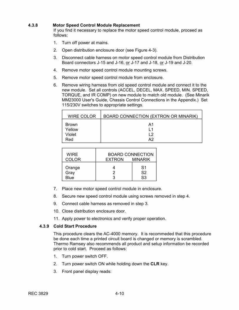
4.3.8 Motor Speed Control Module ReplacementIf you find it necessary to replace the motor speed control module, proceed asfollows:
1. Turn off power at mains.
2. Open distribution enclosure door (see Figure 4-3).
3. Disconnect cable harness on motor speed control module from DistributionBoard connectors J-15 and J-16, or J-17 and J-18, or J-19 and J-20.
4. Remove motor speed control module mounting screws.
5. Remove motor speed control module from enclosure.
6. Remove wiring harness from old speed control module and connect it to thenew module. Set all controls (ACCEL, DECEL, MAX. SPEED, MIN. SPEED,TORQUE, and IR COMP) on new module to match old module. (See MinarikMM23000 User's Guide, Chassis Control Connections in the Appendix.) Set115/230V switches to appropriate settings.
WIRE COLOR BOARD CONNECTION (EXTRON OR MINARIK)
BrownYellowVioletRed
A1L1L2A2
WIRECOLOR
BOARD CONNECTION EXTRON MINARIK
OrangeGrayBlue
423
S1S2S3
7. Place new motor speed control module in enclosure.
8. Secure new speed control module using screws removed in step 4.
9. Connect cable harness as removed in step 3.
10. Close distribution enclosure door.
11. Apply power to electronics and verify proper operation.
4.3.9 Cold Start Procedure
This procedure clears the AC-4000 memory. It is recommeded that this procedurebe done each time a printed circuit board is changed or memory is scrambled. Thermo Ramsey also recommends all product and setup information be recordedprior to cold start. Proceed as follows:
1. Turn power switch OFF.
2. Turn power switch ON while holding down the CLR key.
3. Front panel display reads:
REC 3829 4-11
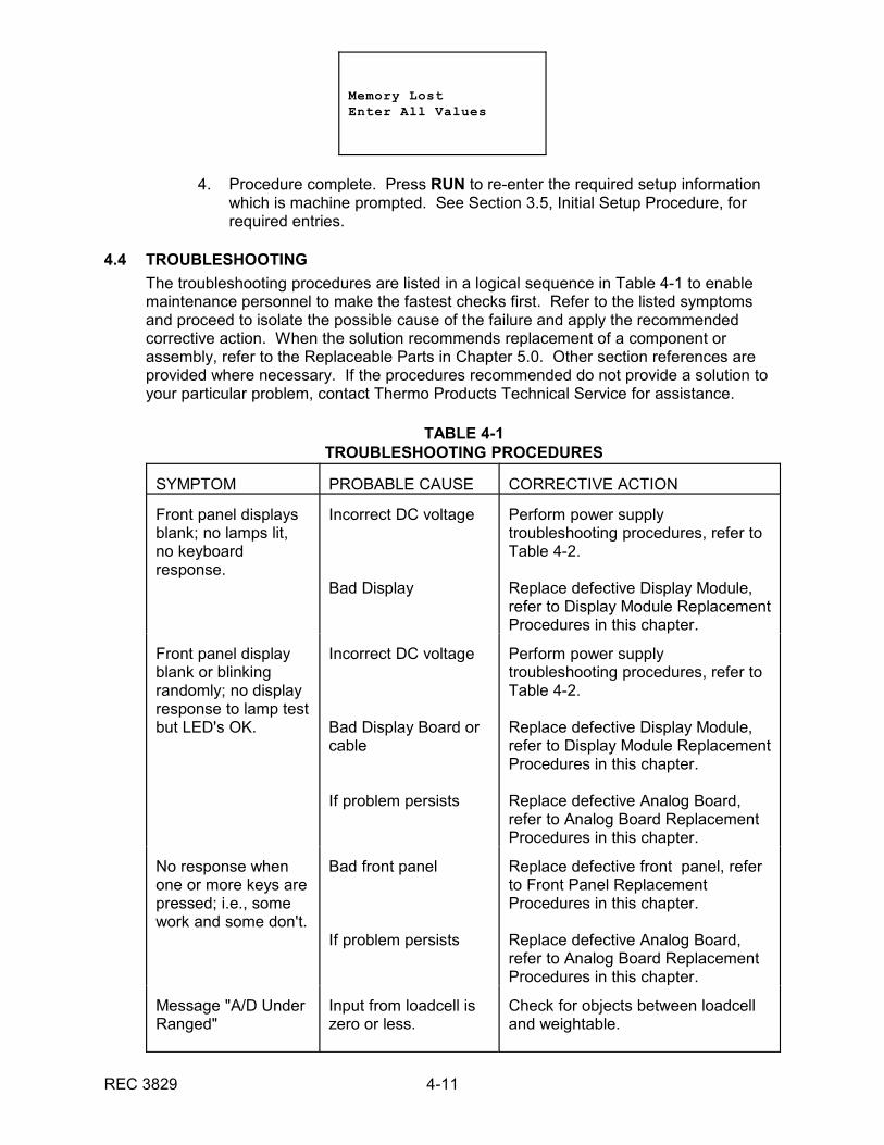
Memory LostEnter All Values
4. Procedure complete. Press RUN to re-enter the required setup informationwhich is machine prompted. See Section 3.5, Initial Setup Procedure, forrequired entries.
4.4 TROUBLESHOOTING
The troubleshooting procedures are listed in a logical sequence in Table 4-1 to enablemaintenance personnel to make the fastest checks first. Refer to the listed symptomsand proceed to isolate the possible cause of the failure and apply the recommendedcorrective action. When the solution recommends replacement of a component orassembly, refer to the Replaceable Parts in Chapter 5.0. Other section references areprovided where necessary. If the procedures recommended do not provide a solution toyour particular problem, contact Thermo Products Technical Service for assistance.
TABLE 4-1TROUBLESHOOTING PROCEDURES
SYMPTOM PROBABLE CAUSE CORRECTIVE ACTION
Front panel displaysblank; no lamps lit,no keyboardresponse.
Incorrect DC voltage
Bad Display
Perform power supplytroubleshooting procedures, refer toTable 4-2.
Replace defective Display Module,refer to Display Module ReplacementProcedures in this chapter.
Front panel displayblank or blinkingrandomly; no displayresponse to lamp testbut LED's OK.
Incorrect DC voltage
Bad Display Board orcable
If problem persists
Perform power supplytroubleshooting procedures, refer toTable 4-2.
Replace defective Display Module,refer to Display Module ReplacementProcedures in this chapter.
Replace defective Analog Board,refer to Analog Board ReplacementProcedures in this chapter.
No response whenone or more keys arepressed; i.e., somework and some don't.
Bad front panel
If problem persists
Replace defective front panel, referto Front Panel ReplacementProcedures in this chapter.
Replace defective Analog Board,refer to Analog Board ReplacementProcedures in this chapter.
Message "A/D UnderRanged"
Input from loadcell iszero or less.
Check for objects between loadcelland weightable.
REC 3829 4-12
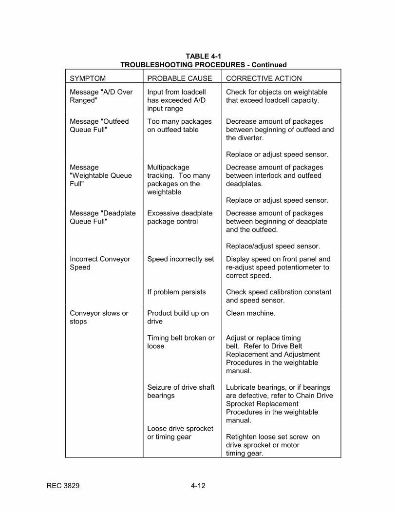
TABLE 4-1TROUBLESHOOTING PROCEDURES - Continued
SYMPTOM PROBABLE CAUSE CORRECTIVE ACTION
Message "A/D OverRanged"
Input from loadcellhas exceeded A/Dinput range
Check for objects on weightablethat exceed loadcell capacity.
Message "OutfeedQueue Full"
Too many packageson outfeed table
Decrease amount of packagesbetween beginning of outfeed andthe diverter.
Replace or adjust speed sensor.
Message"Weightable QueueFull"
Multipackagetracking. Too manypackages on theweightable
Decrease amount of packagesbetween interlock and outfeeddeadplates.
Replace or adjust speed sensor.
Message "DeadplateQueue Full"
Excessive deadplatepackage control
Decrease amount of packagesbetween beginning of deadplateand the outfeed.
Replace/adjust speed sensor.
Incorrect ConveyorSpeed
Speed incorrectly set
If problem persists
Display speed on front panel andre-adjust speed potentiometer tocorrect speed.
Check speed calibration constantand speed sensor.
Conveyor slows orstops
Product build up ondrive
Timing belt broken orloose
Seizure of drive shaftbearings
Loose drive sprocketor timing gear
Clean machine.
Adjust or replace timingbelt. Refer to Drive BeltReplacement and AdjustmentProcedures in the weightablemanual.
Lubricate bearings, or if bearingsare defective, refer to Chain DriveSprocket ReplacementProcedures in the weightablemanual.
Retighten loose set screw ondrive sprocket or motortiming gear.
REC 3829 4-13
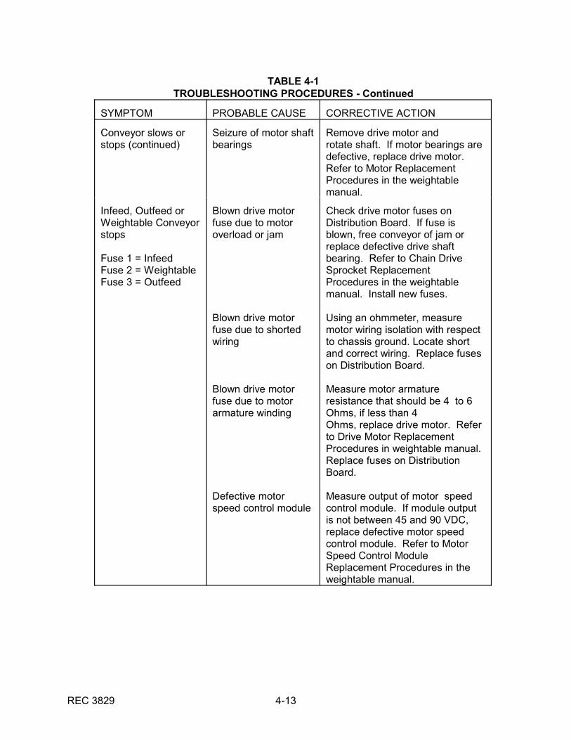
TABLE 4-1TROUBLESHOOTING PROCEDURES - Continued
SYMPTOM PROBABLE CAUSE CORRECTIVE ACTION
Conveyor slows orstops (continued)
Seizure of motor shaftbearings
Remove drive motor androtate shaft. If motor bearings aredefective, replace drive motor. Refer to Motor ReplacementProcedures in the weightablemanual.
Infeed, Outfeed orWeightable Conveyorstops
Fuse 1 = InfeedFuse 2 = WeightableFuse 3 = Outfeed
Blown drive motorfuse due to motoroverload or jam
Blown drive motorfuse due to shortedwiring
Blown drive motorfuse due to motorarmature winding
Defective motorspeed control module
Check drive motor fuses onDistribution Board. If fuse isblown, free conveyor of jam orreplace defective drive shaftbearing. Refer to Chain DriveSprocket ReplacementProcedures in the weightablemanual. Install new fuses.
Using an ohmmeter, measuremotor wiring isolation with respectto chassis ground. Locate shortand correct wiring. Replace fuseson Distribution Board.
Measure motor armatureresistance that should be 4 to 6Ohms, if less than 4 Ohms, replace drive motor. Referto Drive Motor ReplacementProcedures in weightable manual. Replace fuses on DistributionBoard.
Measure output of motor speedcontrol module. If module outputis not between 45 and 90 VDC,replace defective motor speedcontrol module. Refer to MotorSpeed Control ModuleReplacement Procedures in theweightable manual.
REC 3829 4-14
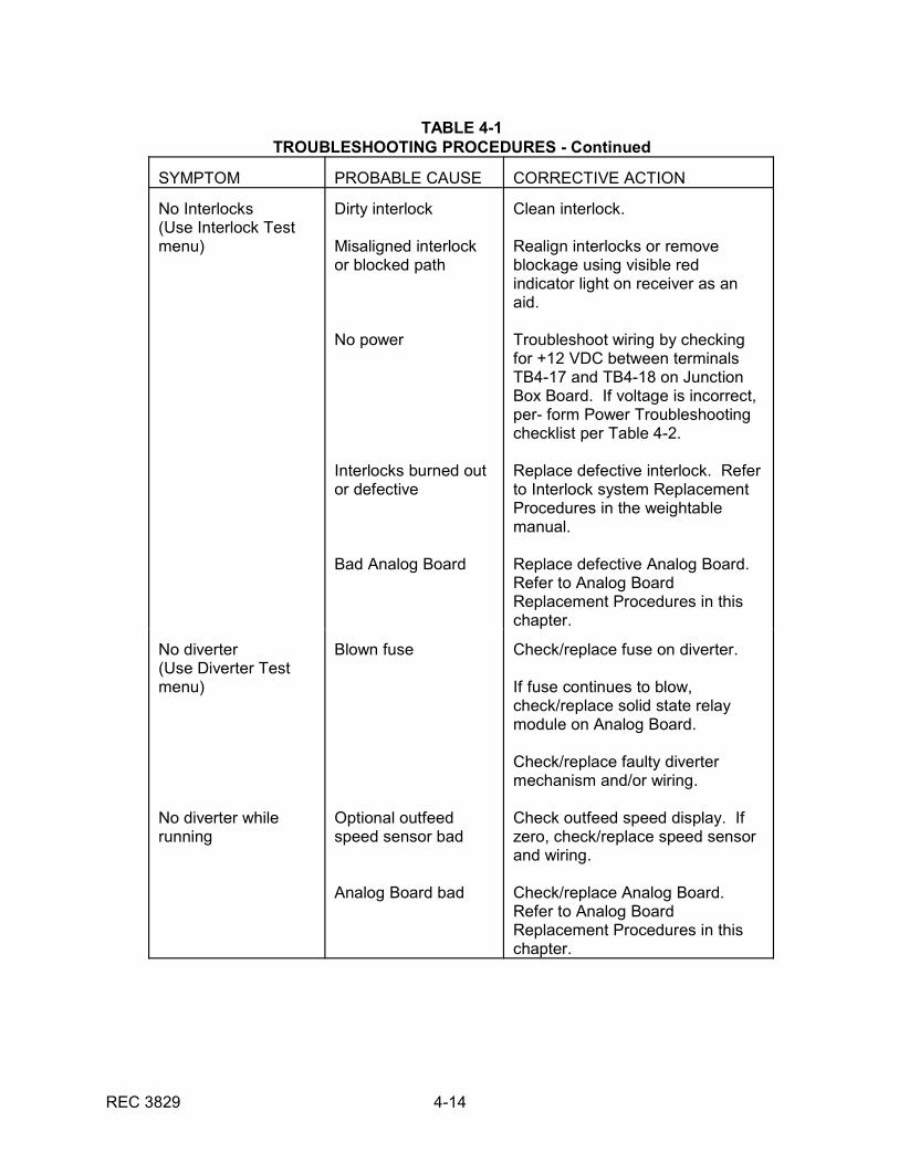
TABLE 4-1TROUBLESHOOTING PROCEDURES - Continued
SYMPTOM PROBABLE CAUSE CORRECTIVE ACTION
No Interlocks(Use Interlock Testmenu)
Dirty interlock
Misaligned interlockor blocked path
No power
Interlocks burned outor defective
Bad Analog Board
Clean interlock.
Realign interlocks or removeblockage using visible redindicator light on receiver as anaid.
Troubleshoot wiring by checkingfor +12 VDC between terminalsTB4-17 and TB4-18 on JunctionBox Board. If voltage is incorrect,per- form Power Troubleshootingchecklist per Table 4-2.
Replace defective interlock. Referto Interlock system ReplacementProcedures in the weightablemanual.
Replace defective Analog Board. Refer to Analog BoardReplacement Procedures in thischapter.
No diverter(Use Diverter Testmenu)
No diverter whilerunning
Blown fuse
Optional outfeedspeed sensor bad
Analog Board bad
Check/replace fuse on diverter.
If fuse continues to blow,check/replace solid state relaymodule on Analog Board.
Check/replace faulty divertermechanism and/or wiring.
Check outfeed speed display. Ifzero, check/replace speed sensorand wiring.
Check/replace Analog Board. Refer to Analog BoardReplacement Procedures in thischapter.
REC 3829 4-15
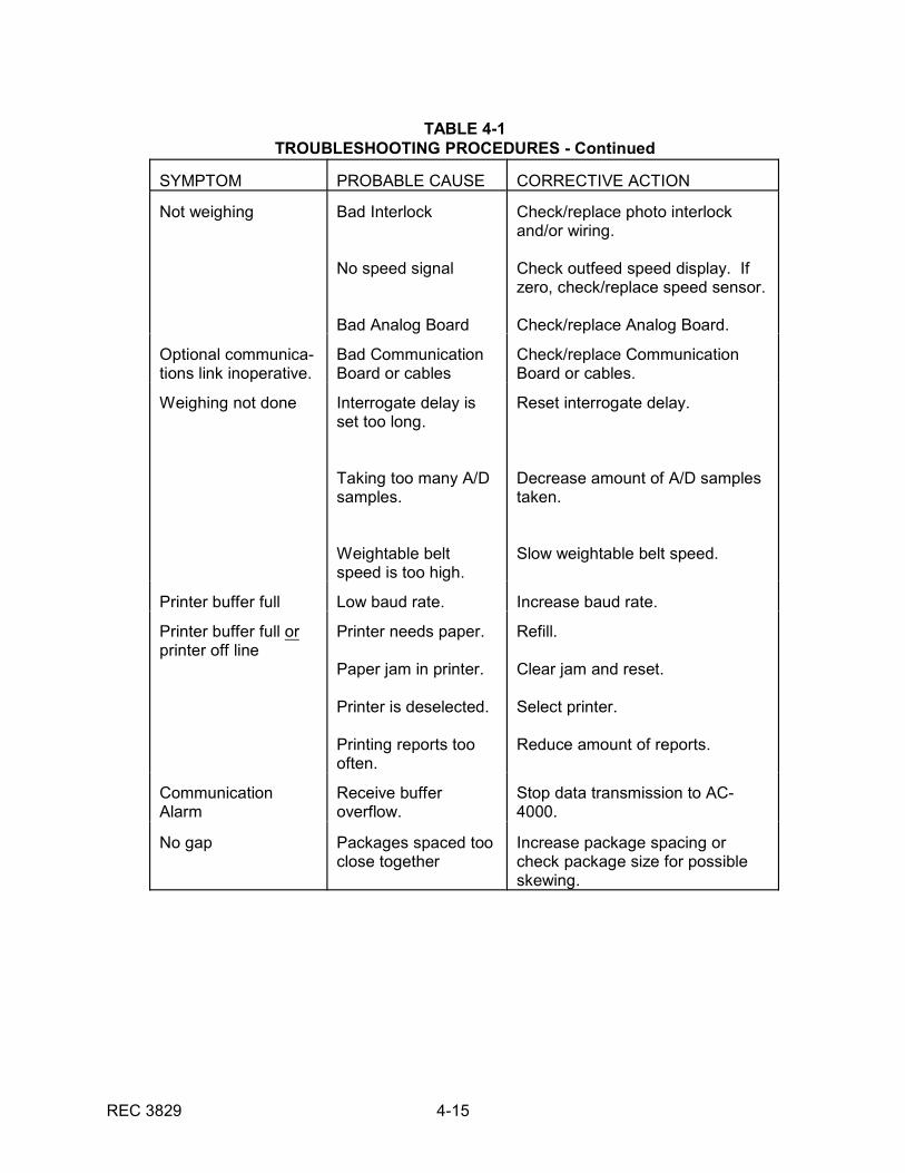
TABLE 4-1TROUBLESHOOTING PROCEDURES - Continued
SYMPTOM PROBABLE CAUSE CORRECTIVE ACTION
Not weighing Bad Interlock
No speed signal
Bad Analog Board
Check/replace photo interlockand/or wiring.
Check outfeed speed display. Ifzero, check/replace speed sensor.
Check/replace Analog Board.
Optional communica-tions link inoperative.
Bad CommunicationBoard or cables
Check/replace CommunicationBoard or cables.
Weighing not done Interrogate delay isset too long.
Taking too many A/Dsamples.
Weightable beltspeed is too high.
Reset interrogate delay.
Decrease amount of A/D samplestaken.
Slow weightable belt speed.
Printer buffer full Low baud rate. Increase baud rate.
Printer buffer full orprinter off line
Printer needs paper.
Paper jam in printer.
Printer is deselected.
Printing reports toooften.
Refill.
Clear jam and reset.
Select printer.
Reduce amount of reports.
CommunicationAlarm
Receive bufferoverflow.
Stop data transmission to AC-4000.
No gap Packages spaced tooclose together
Increase package spacing orcheck package size for possibleskewing.
REC 3829 4-16
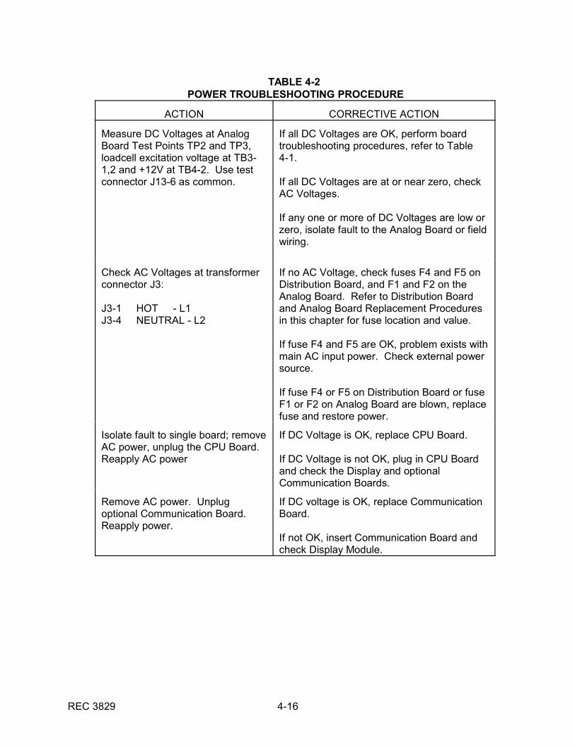
TABLE 4-2 POWER TROUBLESHOOTING PROCEDURE
ACTION CORRECTIVE ACTION
Measure DC Voltages at AnalogBoard Test Points TP2 and TP3,loadcell excitation voltage at TB3-1,2 and +12V at TB4-2. Use testconnector J13-6 as common.
If all DC Voltages are OK, perform boardtroubleshooting procedures, refer to Table4-1.
If all DC Voltages are at or near zero, checkAC Voltages.
If any one or more of DC Voltages are low orzero, isolate fault to the Analog Board or fieldwiring.
Check AC Voltages at transformerconnector J3:
J3-1 HOT - L1J3-4 NEUTRAL - L2
If no AC Voltage, check fuses F4 and F5 onDistribution Board, and F1 and F2 on theAnalog Board. Refer to Distribution Boardand Analog Board Replacement Proceduresin this chapter for fuse location and value.
If fuse F4 and F5 are OK, problem exists withmain AC input power. Check external powersource.
If fuse F4 or F5 on Distribution Board or fuseF1 or F2 on Analog Board are blown, replacefuse and restore power.
Isolate fault to single board; removeAC power, unplug the CPU Board. Reapply AC power
If DC Voltage is OK, replace CPU Board.
If DC Voltage is not OK, plug in CPU Boardand check the Display and optionalCommunication Boards.
Remove AC power. Unplugoptional Communication Board. Reapply power.
If DC voltage is OK, replace CommunicationBoard.
If not OK, insert Communication Board andcheck Display Module.
REC 3829 4-17
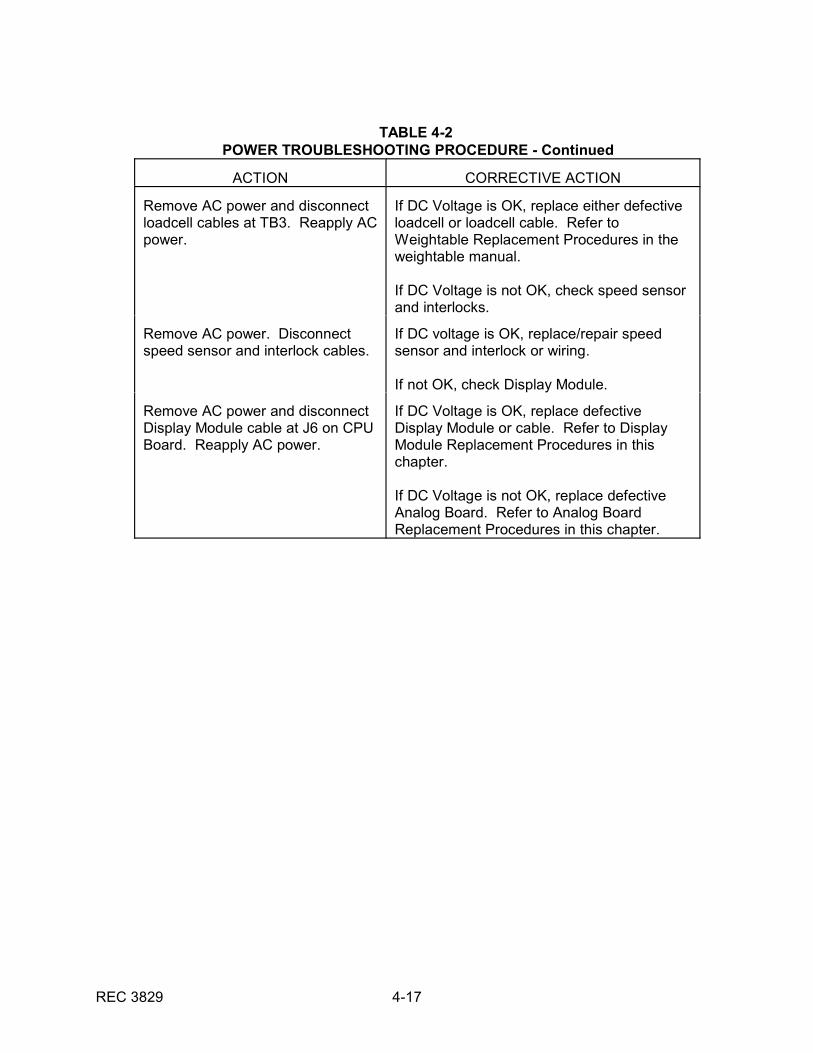
TABLE 4-2 POWER TROUBLESHOOTING PROCEDURE - Continued
ACTION CORRECTIVE ACTION
Remove AC power and disconnectloadcell cables at TB3. Reapply ACpower.
If DC Voltage is OK, replace either defectiveloadcell or loadcell cable. Refer toWeightable Replacement Procedures in theweightable manual.
If DC Voltage is not OK, check speed sensorand interlocks.
Remove AC power. Disconnectspeed sensor and interlock cables.
If DC voltage is OK, replace/repair speedsensor and interlock or wiring.
If not OK, check Display Module.
Remove AC power and disconnectDisplay Module cable at J6 on CPUBoard. Reapply AC power.
If DC Voltage is OK, replace defectiveDisplay Module or cable. Refer to DisplayModule Replacement Procedures in thischapter.
If DC Voltage is not OK, replace defectiveAnalog Board. Refer to Analog BoardReplacement Procedures in this chapter.
REC 3829 5-1
CHAPTER 5.0REPLACEMENT PARTS
5.1 GENERAL
This chapter gives information on how to order replacement parts for your AC-4000Electronics and includes photographs and drawings with corresponding parts lists toenable you to identify parts quickly and accurately.
5.2 ORDER INFORMATION
For faster service when ordering parts, fax or telephone Thermo Products PartsDepartment. Your regional field service representative will also be happy to assist youwith parts orders, but his normal scheduling time may delay shipment of your parts order.
The recommended procedure for ordering parts is as follows:
1. Determine the broken or faulty part(s).
2. Locate the part(s) in the parts list given.
3. Find the part number(s) for the item(s) needed and determine the quantity yourequire.
4. Write or telephone:
Thermo ElectronCustomer Service Department501 90th Ave. NWMinneapolis, Minnesota 55433Fax: (763) 780-1537
Customers A through G - (763)783-2781 Customers H through O - (763)783-2693Customers P through Z - (763)783-2782Repair and Returns - (763)783-2783
Normal Customer Service hours are 8:00 a.m. to 4:30 p.m., Central Time.
5. With your order, list the following information:
Machine model and serial number Purchase order number Date required Method of shipment preferredList of parts, including part number, description and quantity
Your parts order will handled as expeditiously as possible.

REC 3829 5-2
5.3 PARTS LIST INDEX
Parts lists are cross referenced to photographs or drawings to facilitate identification. These parts lists are indexed as follows:
PARTS LIST
DESCRIPTION TABLE NO. PAGE NO.
AC-4000 Electronics (Remote or Local) 5-1 5-4

REC 3829 5-3
5.3.1 Return Material Authorization
REC 3829 5-4
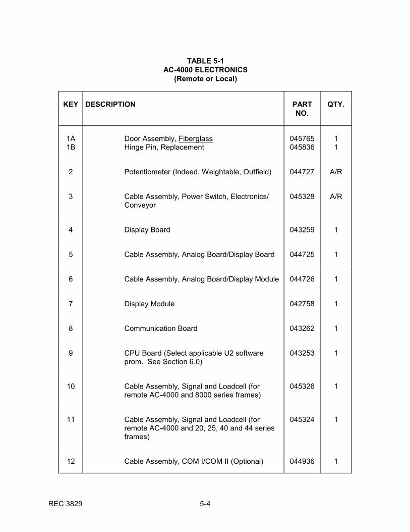
TABLE 5-1AC-4000 ELECTRONICS
(Remote or Local)
KEY DESCRIPTION PARTNO.
QTY.
1A1B
Door Assembly, FiberglassHinge Pin, Replacement
045765045836
11
2 Potentiometer (Indeed, Weightable, Outfield) 044727 A/R
3 Cable Assembly, Power Switch, Electronics/Conveyor
045328 A/R
4 Display Board 043259 1
5 Cable Assembly, Analog Board/Display Board 044725 1
6 Cable Assembly, Analog Board/Display Module 044726 1
7 Display Module 042758 1
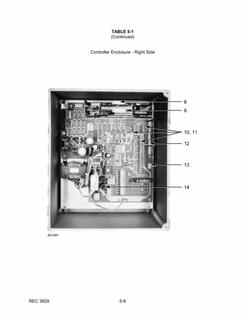
8 Communication Board 043262 1
9 CPU Board (Select applicable U2 softwareprom. See Section 6.0)
043253 1
10 Cable Assembly, Signal and Loadcell (forremote AC-4000 and 8000 series frames)
045326 1
11 Cable Assembly, Signal and Loadcell (forremote AC-4000 and 20, 25, 40 and 44 seriesframes)
045324 1
12 Cable Assembly, COM I/COM II (Optional) 044936 1
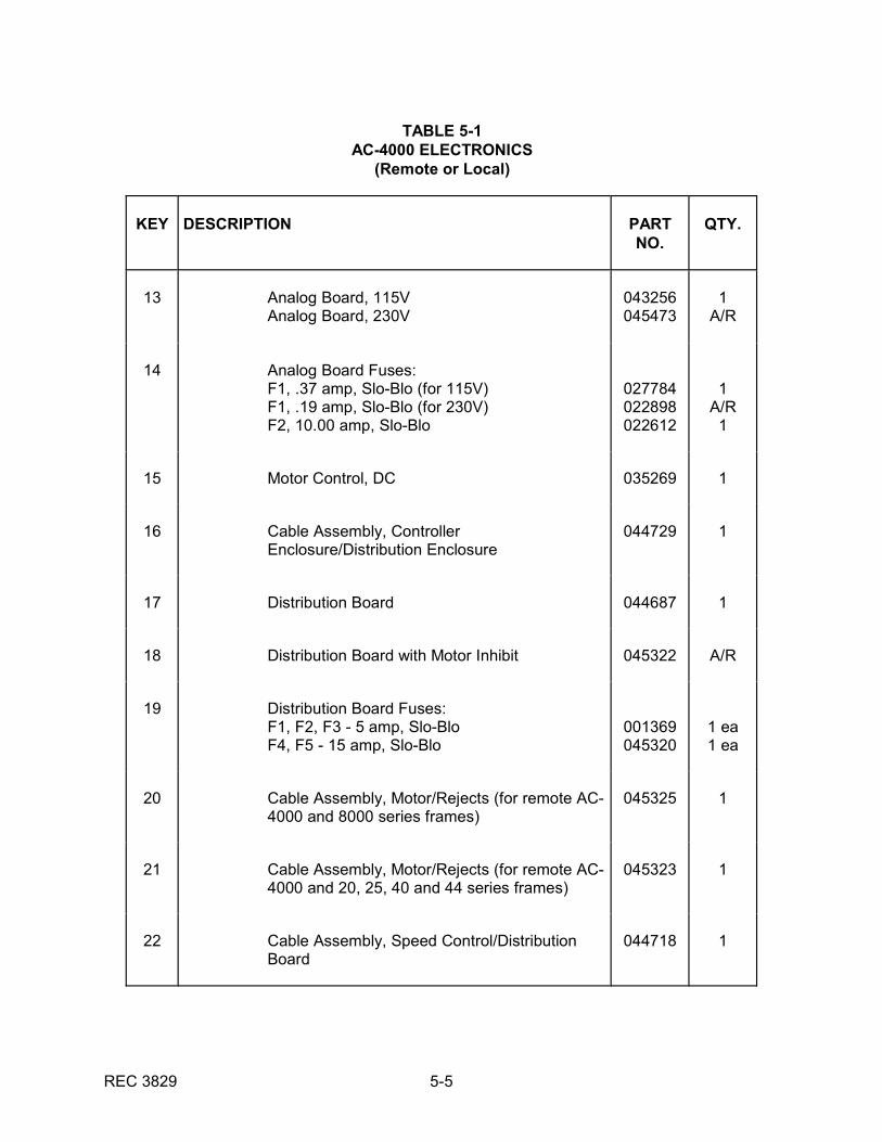
TABLE 5-1AC-4000 ELECTRONICS
(Remote or Local)
KEY DESCRIPTION PARTNO.
QTY.
REC 3829 5-5
13 Analog Board, 115VAnalog Board, 230V
043256045473
1A/R
14 Analog Board Fuses:F1, .37 amp, Slo-Blo (for 115V)F1, .19 amp, Slo-Blo (for 230V)F2, 10.00 amp, Slo-Blo
027784022898022612
1A/R
1
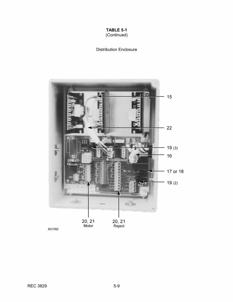
15 Motor Control, DC 035269 1
16 Cable Assembly, ControllerEnclosure/Distribution Enclosure
044729 1
17 Distribution Board 044687 1
18 Distribution Board with Motor Inhibit 045322 A/R
19 Distribution Board Fuses:F1, F2, F3 - 5 amp, Slo-BloF4, F5 - 15 amp, Slo-Blo
001369045320
1 ea1 ea
20 Cable Assembly, Motor/Rejects (for remote AC-4000 and 8000 series frames)
045325 1
21 Cable Assembly, Motor/Rejects (for remote AC-4000 and 20, 25, 40 and 44 series frames)
045323 1
22 Cable Assembly, Speed Control/DistributionBoard
044718 1
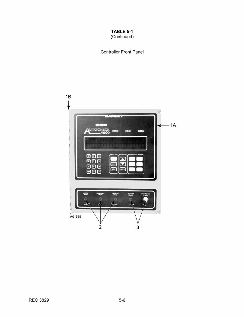
REC 3829 5-6
TABLE 5-1(Continued)
Controller Front Panel
REC 3829 5-7
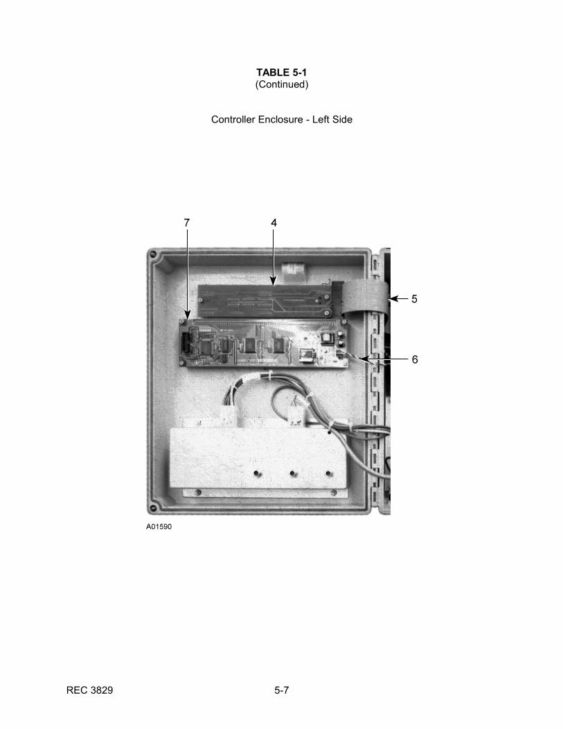
TABLE 5-1(Continued)
Controller Enclosure - Left Side
REC 3829 5-8
TABLE 5-1(Continued)
Controller Enclosure - Right Side
REC 3829 5-9
TABLE 5-1(Continued)
Distribution Enclosure
REC 3829 6-1
CHAPTER 6.0AC-4000 OPTIONS
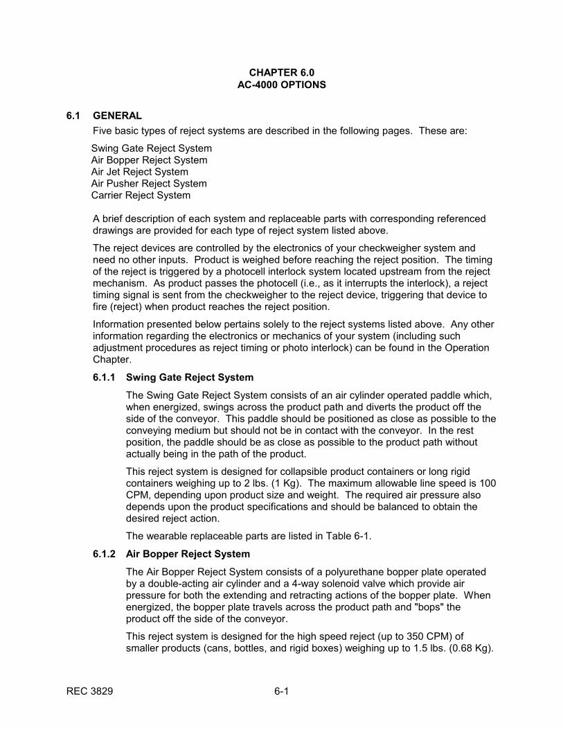
6.1 GENERAL
Five basic types of reject systems are described in the following pages. These are:
Swing Gate Reject SystemAir Bopper Reject SystemAir Jet Reject SystemAir Pusher Reject SystemCarrier Reject System
A brief description of each system and replaceable parts with corresponding referenceddrawings are provided for each type of reject system listed above.
The reject devices are controlled by the electronics of your checkweigher system andneed no other inputs. Product is weighed before reaching the reject position. The timingof the reject is triggered by a photocell interlock system located upstream from the rejectmechanism. As product passes the photocell (i.e., as it interrupts the interlock), a rejecttiming signal is sent from the checkweigher to the reject device, triggering that device tofire (reject) when product reaches the reject position.
Information presented below pertains solely to the reject systems listed above. Any otherinformation regarding the electronics or mechanics of your system (including suchadjustment procedures as reject timing or photo interlock) can be found in the OperationChapter.
6.1.1 Swing Gate Reject System
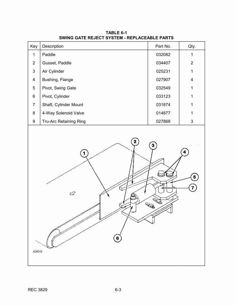
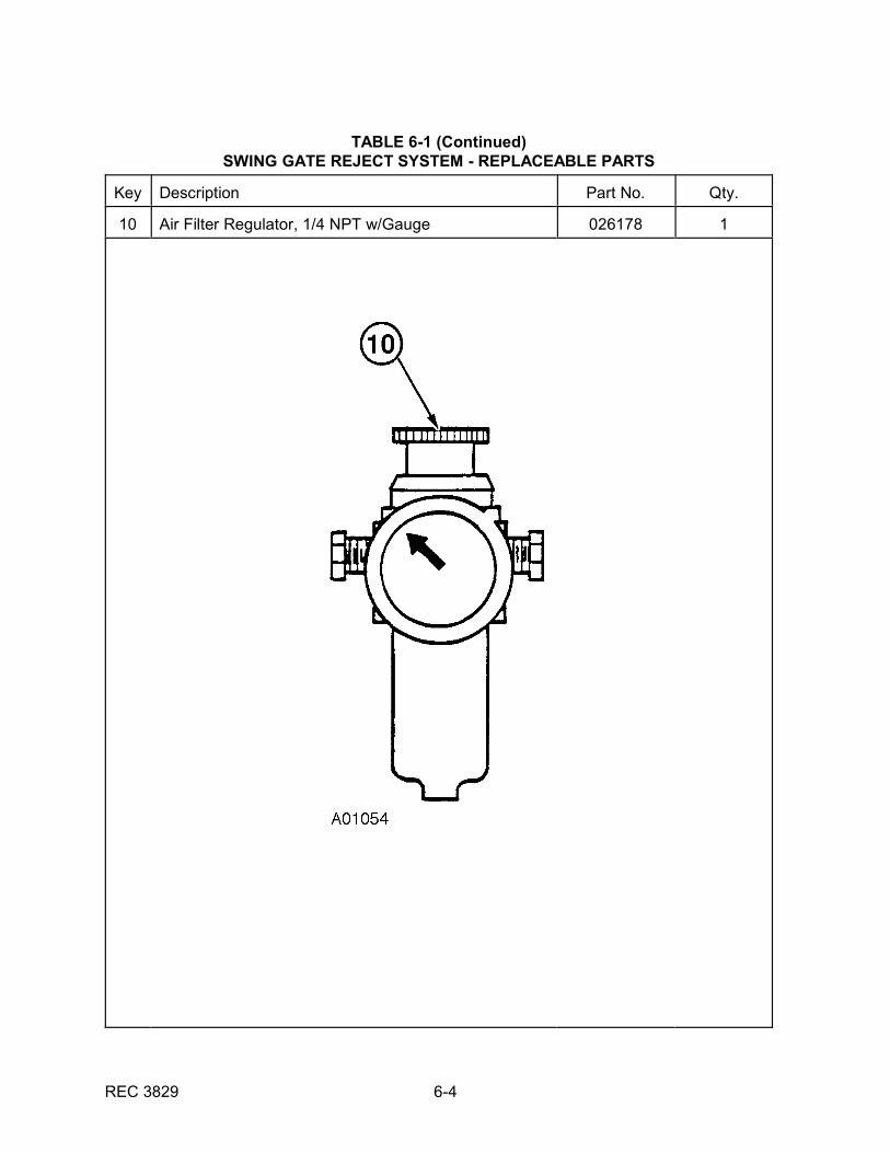
The Swing Gate Reject System consists of an air cylinder operated paddle which,when energized, swings across the product path and diverts the product off theside of the conveyor. This paddle should be positioned as close as possible to theconveying medium but should not be in contact with the conveyor. In the restposition, the paddle should be as close as possible to the product path withoutactually being in the path of the product.
This reject system is designed for collapsible product containers or long rigidcontainers weighing up to 2 lbs. (1 Kg). The maximum allowable line speed is 100CPM, depending upon product size and weight. The required air pressure alsodepends upon the product specifications and should be balanced to obtain thedesired reject action.
The wearable replaceable parts are listed in Table 6-1.
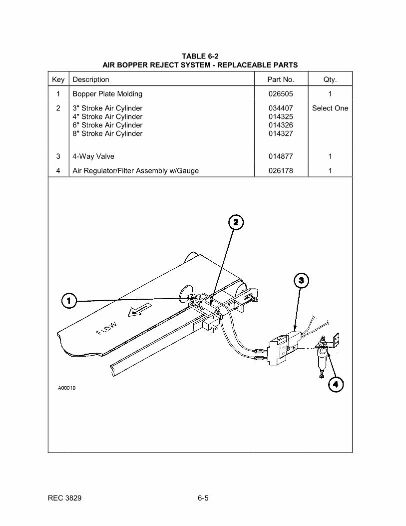
6.1.2 Air Bopper Reject System
The Air Bopper Reject System consists of a polyurethane bopper plate operatedby a double-acting air cylinder and a 4-way solenoid valve which provide airpressure for both the extending and retracting actions of the bopper plate. Whenenergized, the bopper plate travels across the product path and "bops" theproduct off the side of the conveyor.
This reject system is designed for the high speed reject (up to 350 CPM) ofsmaller products (cans, bottles, and rigid boxes) weighing up to 1.5 lbs. (0.68 Kg).

REC 3829 6-2
The Air Bopper Reject should be mounted perpendicular to the conveying mediumand as close as possible (without touching) to the product and the conveyingmedium. The air pressure required depends on product specifications and shouldbe balanced to obtain the desired reject action.
The wearable replaceable parts are listed in Table 6-2.
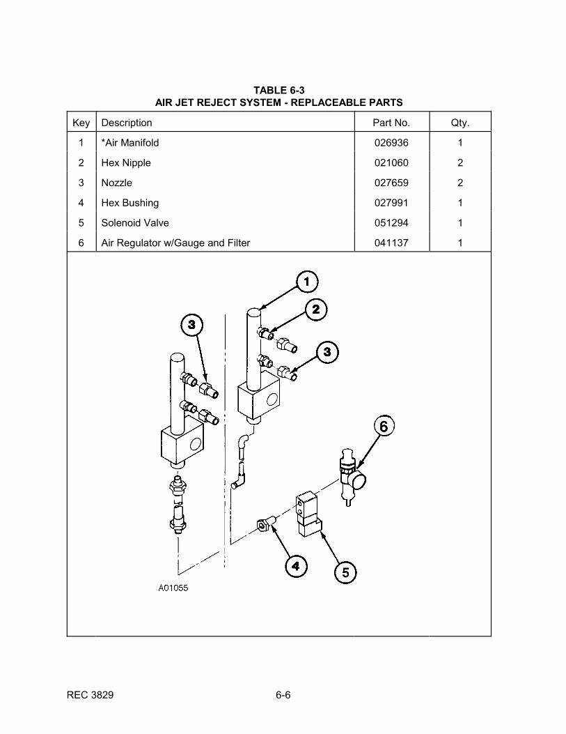
6.1.3 Air Jet Reject System
The Air Jet Reject System consists of two (2) OSHA approved air nozzlesmounted on an air manifold and controlled by a solenoid valve. When energized,jets of air blow the product off the conveying medium. To avoid possiblecontamination of the air supply, the system's air filter and regulator assembly doesnot contain a lubricator. The air pressure required depends on product weight andshould be adjusted to obtain the desired reject action.
This reject system is designed for rigid product containers weighing up to 2.5 lbs.(1.1 Kg) for chain conveyor applications and up to 1 lb. (0.5 Kg) for mylar beltconveyor applications. The maximum allowable line speed for this reject system is400 CPM, depending upon product size and weight.
The wearable replaceable parts are listed in Table 6-3.
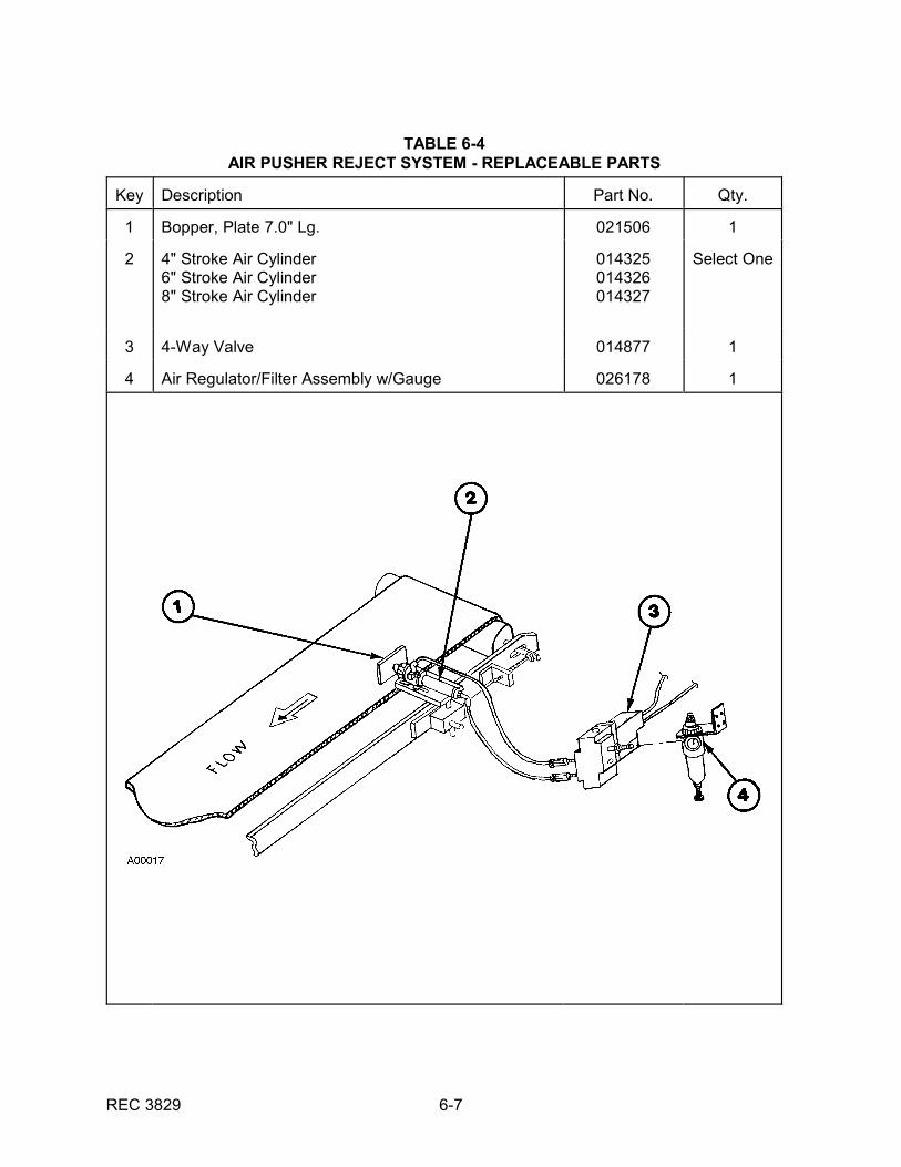
6.1.4 Air Pusher Reject System
The Air Pusher Reject System consists of a stainless steel rectangular plate or ananodized aluminum round plate operated by a double acting air cylinder and a 4-way solenoid valve which provide air pressure for both the extending and theretracting actions, of the reject plate. When energized, the Air Pusher platetravels across the product path and pushes the product off the side of theconveyor.
This reject system is designed for heavier products, 5 to 40 lbs. (2.3 to 28 Kg),and slower line speeds (40 to 80 CPM). The round reject plate is used for rigidproduct containers. The rectangular reject plate is used for collapsible productcontainers.
The Air Pusher Reject should be positioned as close as possible to (withouttouching) the product. It should be mounted as close as possible to the conveyingmedium to prevent tipping the product when rejected. This height is generallyabout the mid-section of the product container. The air pressure requireddepends upon product specifications and should be balanced to obtain the desiredreject action.
The wearable replaceable parts are presented in Table 6-4.
6.1.5 Carrier Reject System
The Carrier Reject System represents the most gentle handling mechanism knowfor rejection applications. A series of channels (from one to five) is built into thecarrier reject and signals from the checkweigher cause the carrier plaques todivert product to the desired channel. This reject system operates at any speedand handles products of any size and weight compatible with the electronics.
REC 3829 6-3
TABLE 6-1SWING GATE REJECT SYSTEM - REPLACEABLE PARTS
Key Description Part No. Qty.
1 Paddle 032082 1
2 Gusset, Paddle 034407 2
3 Air Cylinder 025231 1
4 Bushing, Flange 027907 4
5 Pivot, Swing Gate 032549 1
6 Pivot, Cylinder 033123 1
7 Shaft, Cylinder Mount 031874 1
8 4-Way Solenoid Valve 014877 1
9 Tru-Arc Retaining Ring 027868 3
REC 3829 6-4
TABLE 6-1 (Continued)SWING GATE REJECT SYSTEM - REPLACEABLE PARTS
Key Description Part No. Qty.
10 Air Filter Regulator, 1/4 NPT w/Gauge 026178 1
REC 3829 6-5
TABLE 6-2AIR BOPPER REJECT SYSTEM - REPLACEABLE PARTS
Key Description Part No. Qty.
1 Bopper Plate Molding 026505 1
2 3" Stroke Air Cylinder4" Stroke Air Cylinder6" Stroke Air Cylinder8" Stroke Air Cylinder
034407014325014326014327
Select One
3 4-Way Valve 014877 1
4 Air Regulator/Filter Assembly w/Gauge 026178 1
REC 3829 6-6
TABLE 6-3AIR JET REJECT SYSTEM - REPLACEABLE PARTS
Key Description Part No. Qty.
1 *Air Manifold 026936 1
2 Hex Nipple 021060 2
3 Nozzle 027659 2
4 Hex Bushing 027991 1
5 Solenoid Valve 051294 1
6 Air Regulator w/Gauge and Filter 041137 1
REC 3829 6-7
TABLE 6-4AIR PUSHER REJECT SYSTEM - REPLACEABLE PARTS
Key Description Part No. Qty.
1 Bopper, Plate 7.0" Lg. 021506 1
2 4" Stroke Air Cylinder6" Stroke Air Cylinder8" Stroke Air Cylinder
014325014326014327
Select One
3 4-Way Valve 014877 1
4 Air Regulator/Filter Assembly w/Gauge 026178 1
REC 3829 6-8
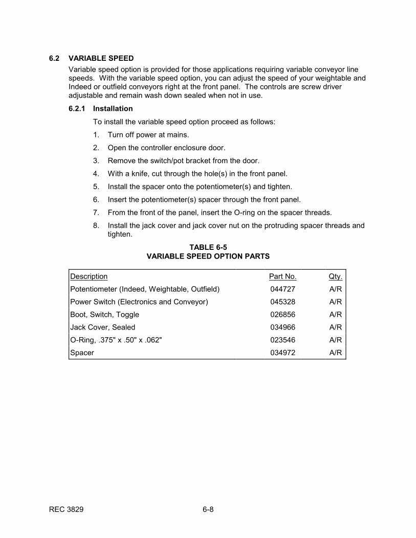
6.2 VARIABLE SPEED
Variable speed option is provided for those applications requiring variable conveyor linespeeds. With the variable speed option, you can adjust the speed of your weightable andIndeed or outfield conveyors right at the front panel. The controls are screw driveradjustable and remain wash down sealed when not in use.
6.2.1 Installation
To install the variable speed option proceed as follows:
1. Turn off power at mains.
2. Open the controller enclosure door.
3. Remove the switch/pot bracket from the door.
4. With a knife, cut through the hole(s) in the front panel.
5. Install the spacer onto the potentiometer(s) and tighten.
6. Insert the potentiometer(s) spacer through the front panel.
7. From the front of the panel, insert the O-ring on the spacer threads.
8. Install the jack cover and jack cover nut on the protruding spacer threads andtighten.
TABLE 6-5VARIABLE SPEED OPTION PARTS
Description Part No. Qty.
Potentiometer (Indeed, Weightable, Outfield) 044727 A/R
Power Switch (Electronics and Conveyor) 045328 A/R
Boot, Switch, Toggle 026856 A/R
Jack Cover, Sealed 034966 A/R
O-Ring, .375" x .50" x .062" 023546 A/R
Spacer 034972 A/R

REC 3829 6-9
6.3 COMMUNICATIONS
The Communications Option provides two communication channels, Port A and Port B,which are electrically identical but have different functional capabilities. This providesdigital communication with external devices such as printers, terminals, or computers. Both EIA-232 and EIA-422/485 communications standards are supported on bothchannels. Baud rate, character size, parity, and stop bit settings can be selected from thefront panel. Port A can be used to transmit formatted reports or free run data. Port B canbe used to transmit free run data or for other optional functions. Several Port B softwareoptions are available and are described in the AC-4000 Communications SoftwareOptions Manual, REC 4059.
6.3.1 Communication Board Installation
To install the Communication Board and cable, proceed as follows:
1. Turn off power at mains.
2. Open electronics controller enclosure door.
3. The Communication Board connector is located directly above the CPU Boardnear the upper, back portion of the enclosure (see Figure 4-2).
4. Gently push the Communication Board onto the pin connectors using the cardhandle.
5. Insure the board is properly oriented and fully seated.
6. Set dip switches (shown below in Table 6-6) on the Communication Board(Figure 6-1) as needed.
7. Connect the 20 pin connector on the communications cable assembly to J11of the Analog board.
8. Remove two of the cover plates on the bottom of the enclosure and discard. Insert the circular connectors in the holes and tighten the four hex nuts.
9. Close electronics controller enclosure door.
10. Apply power to electronics.
11. Refer to Chapter 3 of this manual for setup procedures. Also see the MenuTree drawing for menus that are available with the Communications Option.

REC 3829 6-10
TABLE 6-6COMMUNICATION BOARD SWITCH SETTINGS
PORT A
SWITCHSW1-1
SWITCHSW1-2
SWITCHSW1-5
SWITCHSW1-7
SWITCHSW2-1 DESCRIPTION
OFF / OPEN OFF / OPEN ON / CLOSED OFF / OPEN OFF / OPEN EIA-232 with hardware
OFF / OPEN ON / CLOSED ON / CLOSED OFF / OPEN OFF / OPEN EIA-232 with data leads only
ON / CLOSED ON / CLOSED ON / CLOSED OFF / OPEN OFF / OPEN EIA-422/485 no termination
ON / CLOSED ON / CLOSED ON / CLOSED ON / CLOSED OFF / OPEN EIA-422/485 with termination
ON / CLOSED ON / CLOSED OFF / OPEN OFF / OPEN OFF / OPEN EIA-422/485 no termination
ON / CLOSED ON / CLOSED OFF / OPEN ON / CLOSED OFF / OPEN EIA-422/485 with termination
ON / CLOSED ON / CLOSED OFF / OPEN OFF / OPEN ON / CLOSED EIA-422/485 no termination
ON / CLOSED ON / CLOSED OFF / OPEN ON / CLOSED ON / CLOSED EIA-422/485 with termination
PORT B
SWITCHSW1-3
SWITCHSW1-4
SWITCHSW1-6
SWITCHSW1-8
SWITCHSW2-2 DESCRIPTION
OFF / OPEN OFF / OPEN ON / CLOSED OFF / OPEN OFF / OPEN EIA-232 with hardware
OFF / OPEN ON / CLOSED ON / CLOSED OFF / OPEN OFF / OPEN EIA-232 data leads only
ON / CLOSED ON / CLOSED ON / CLOSED OFF / OPEN OFF / OPEN EIA-422/485 no termination
ON / CLOSED ON / CLOSED ON / CLOSED ON / CLOSED OFF / OPEN EIA-422/485 with termination
ON / CLOSED ON / CLOSED OFF / OPEN OFF / OPEN OFF / OPEN EIA-422/485 no termination4-wire multidrop
ON / CLOSED ON / CLOSED OFF / OPEN ON / CLOSED OFF / OPEN EIA-422/485 with termination4-wire multidrop
ON / CLOSED ON / CLOSED OFF / OPEN OFF / OPEN ON / CLOSED EIA-422/485 no termination2-wire multidrop
ON / CLOSED ON / CLOSED OFF / OPEN ON / CLOSED ON / CLOSED EIA-422/485 with termination2-wire multidrop
TABLE 6-7COMMUNICATIONS OPTION PARTS
Description Part No. Qty.
Communication Board 043262 1
Com I/Com II Cable Assembly 044936 1
REC 3829 6-11
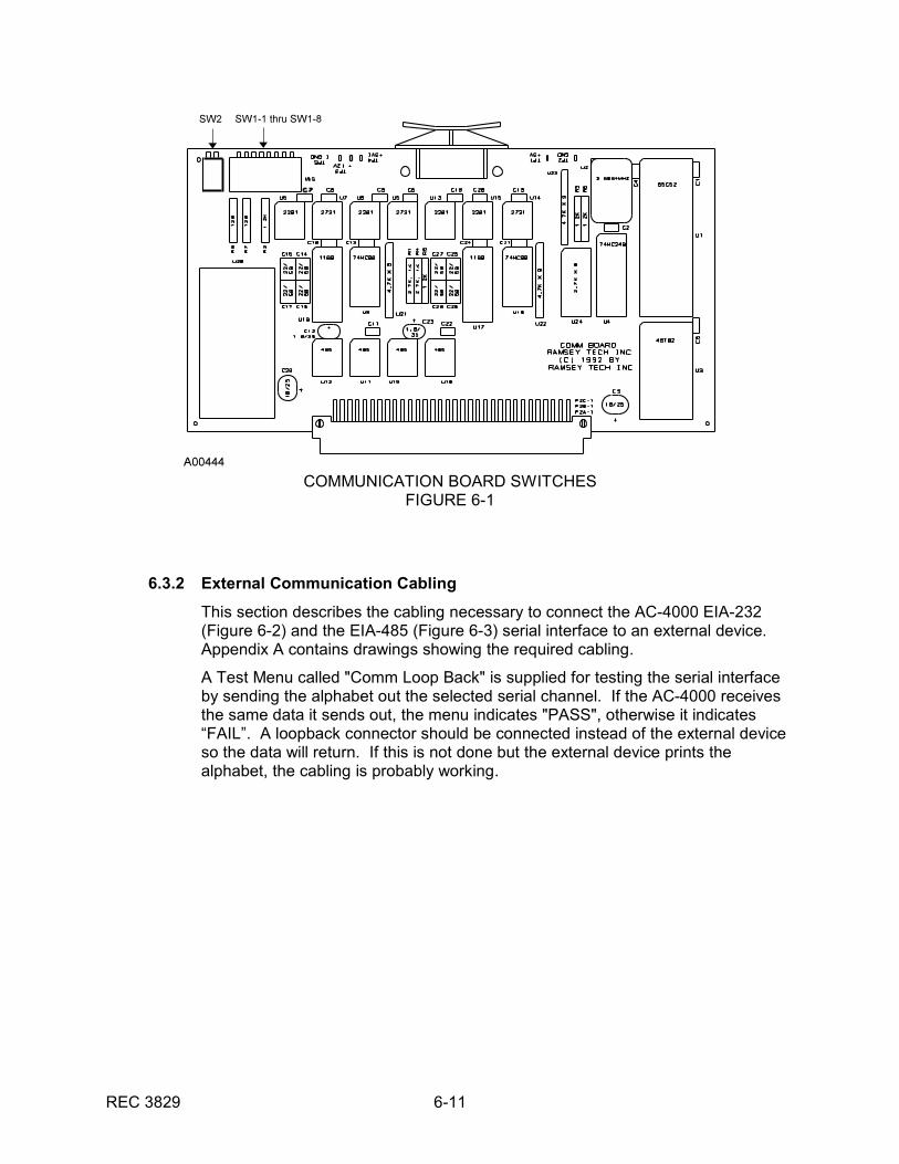
COMMUNICATION BOARD SWITCHESFIGURE 6-1
6.3.2 External Communication Cabling
This section describes the cabling necessary to connect the AC-4000 EIA-232(Figure 6-2) and the EIA-485 (Figure 6-3) serial interface to an external device. Appendix A contains drawings showing the required cabling.
A Test Menu called "Comm Loop Back" is supplied for testing the serial interfaceby sending the alphabet out the selected serial channel. If the AC-4000 receivesthe same data it sends out, the menu indicates "PASS", otherwise it indicates“FAIL”. A loopback connector should be connected instead of the external deviceso the data will return. If this is not done but the external device prints thealphabet, the cabling is probably working.
REC 3829 6-12
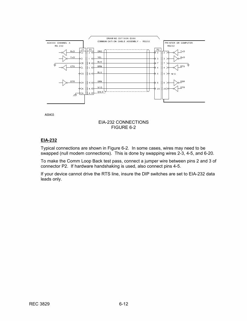
EIA-232 CONNECTIONSFIGURE 6-2
EIA-232
Typical connections are shown in Figure 6-2. In some cases, wires may need to beswapped (null modem connections). This is done by swapping wires 2-3, 4-5, and 6-20.
To make the Comm Loop Back test pass, connect a jumper wire between pins 2 and 3 ofconnector P2. If hardware handshaking is used, also connect pins 4-5.
If your device cannot drive the RTS line, insure the DIP switches are set to EIA-232 dataleads only.
REC 3829 6-13
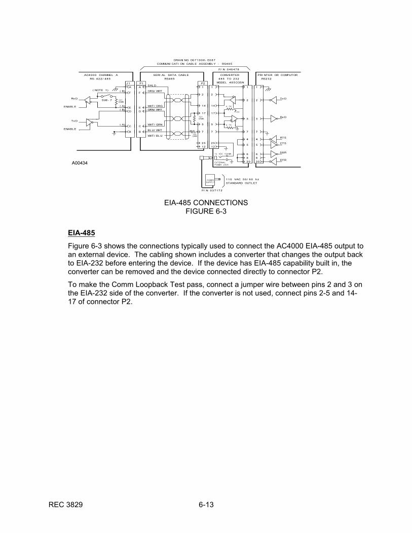
EIA-485 CONNECTIONSFIGURE 6-3
EIA-485
Figure 6-3 shows the connections typically used to connect the AC4000 EIA-485 output toan external device. The cabling shown includes a converter that changes the output backto EIA-232 before entering the device. If the device has EIA-485 capability built in, theconverter can be removed and the device connected directly to connector P2.
To make the Comm Loopback Test pass, connect a jumper wire between pins 2 and 3 onthe EIA-232 side of the converter. If the converter is not used, connect pins 2-5 and 14-17 of connector P2.
REC 3829 6-14
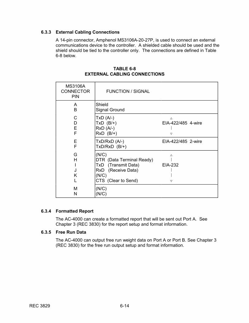
6.3.3 External Cabling Connections
A 14-pin connector, Amphenol MS3106A-20-27P, is used to connect an externalcommunications device to the controller. A shielded cable should be used and theshield should be tied to the controller only. The connections are defined in Table6-8 below.
TABLE 6-8EXTERNAL CABLING CONNECTIONS
MS3106ACONNECTOR
PINFUNCTION / SIGNAL
AB
ShieldSignal Ground
CDEF
TxD (A/-)TxD (B/+)RxD (A/-)RxD (B/+)
ÎEIA-422/485 4-wire , Ï
EF
TxD/RxD (A/-)TxD/RxD (B/+)
EIA-422/485 2-wire
GHIJKL
(N/C) DTR (Data Terminal Ready)TxD (Transmit Data)RxD (Receive Data)(N/C)CTS (Clear to Send)
Î ,EIA-232 , , Ï
MN
(N/C)(N/C)
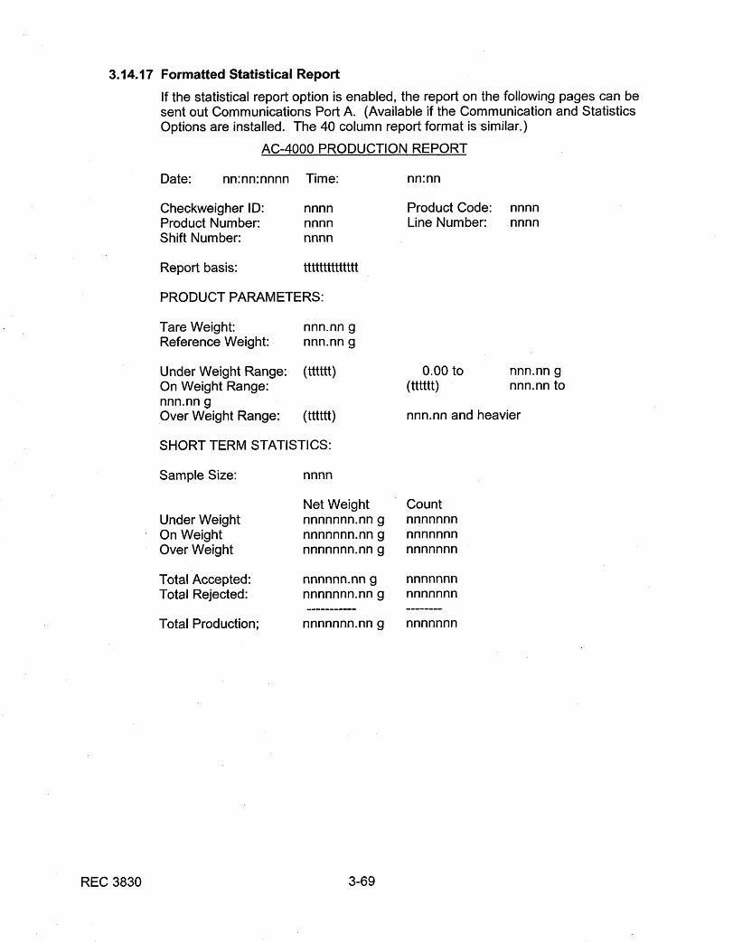
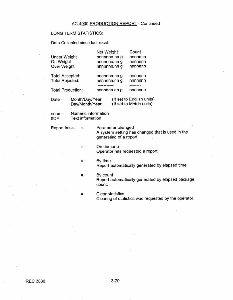
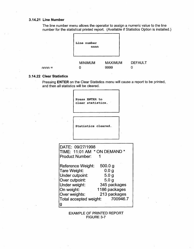
6.3.4 Formatted Report
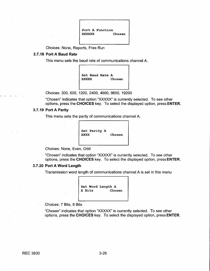
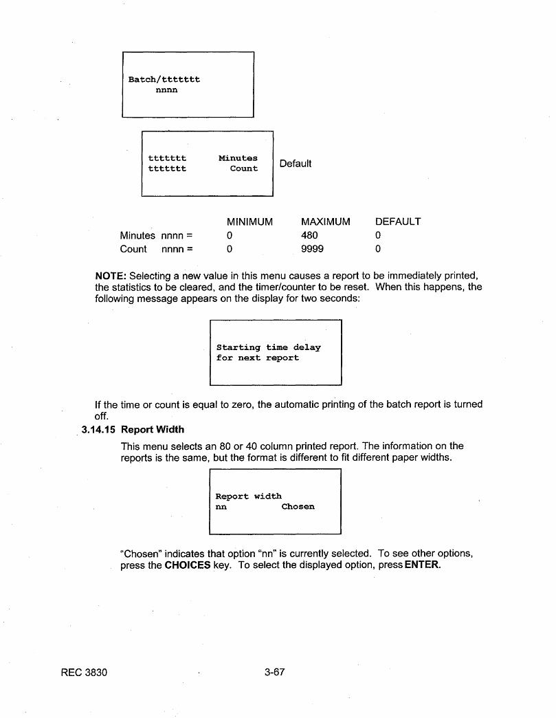
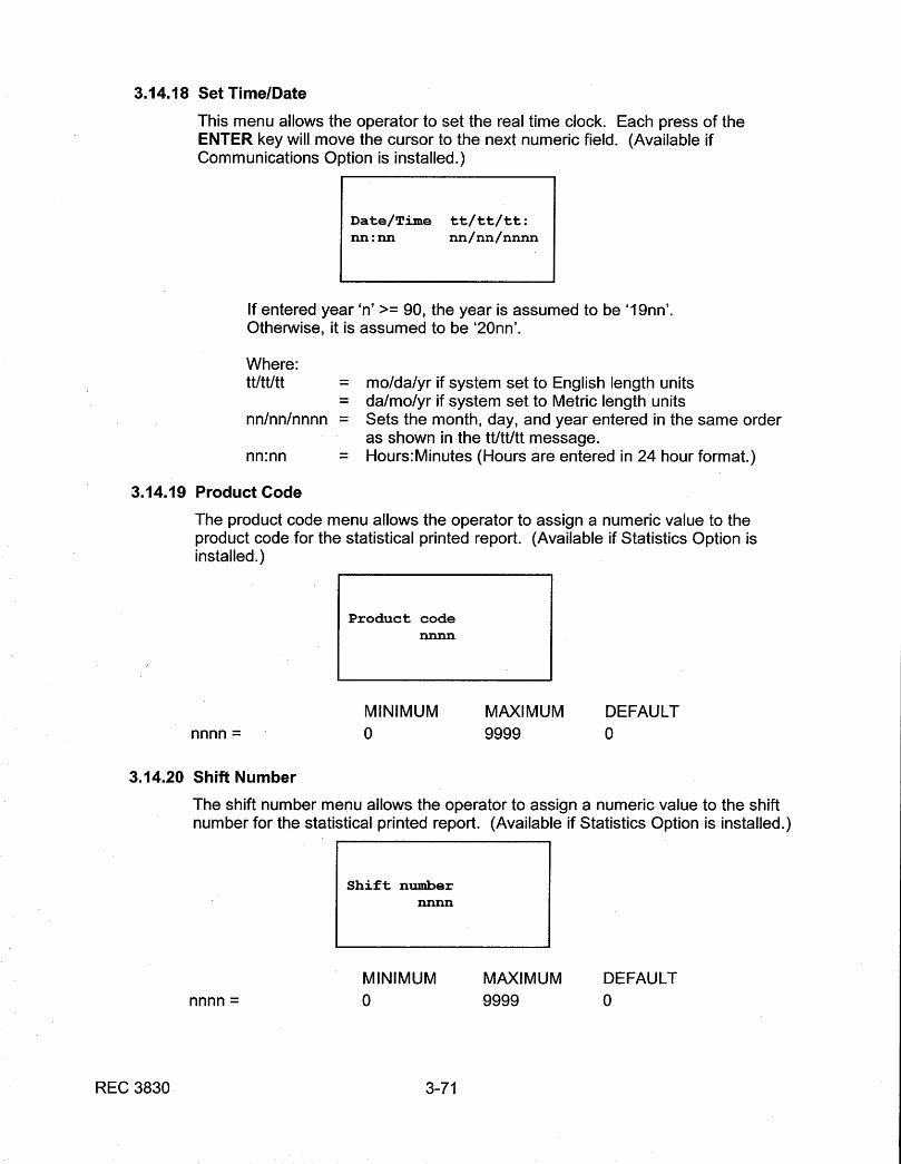
The AC-4000 can create a formatted report that will be sent out Port A. SeeChapter 3 (REC 3830) for the report setup and format information.
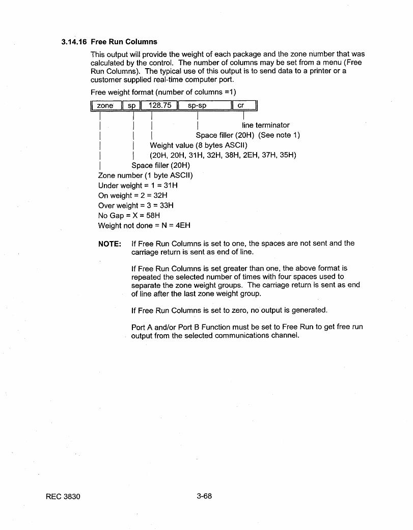
6.3.5 Free Run Data
The AC-4000 can output free run weight data on Port A or Port B. See Chapter 3(REC 3830) for the free run output setup and format information.
REC 3829 6-15
6.4 STATISTICS OPTION
The Statistics Option is provided to gather information on the products being weighed. Ifthe Communications Option is installed, a formatted report of this information can beprinted.
6.4.1 Installation
1. Turn off power at mains.
2. Open electronics controller enclosure door.
3. Locate the CPU Board (directly below the Communication Board) near theupper, back portion of the enclosure (see Figure 4-2).
4. Remove hardware securing CPU board. Gently pull the CPU card handle,extracting the board from the pin connectors.
5. If socket U3 is empty, insert the new Eeprom memory IC into the socket. Theorientation mark is toward U1.
6. Replace CPU Board in enclosure. Insure the board is in the lower slot,properly oriented and fully seated.
7. Perform a Cold Start Procedure.
6. Verify all setups. Refer to Chapter 3 for all setup procedures. Also see theMenu Tree drawing for menus that are available with the Statistics option.
6.5 MULTIPLE PRODUCT OPTION
The Multiple Product Option allows storing of setup parameters and statistical data for upto 15 different products. This information is stored in memory and the AC-4000 can beswitched from one product to another in a matter of seconds by using the Product menu.
6.5.1 Installation
1. Turn off power at mains.
2. Open electronics controller enclosure door.
3. Locate the CPU Board (directly below the Communication Board) near theupper, back portion of the enclosure (see Figure 4-2).
4. Remove hardware securing CPU board. Gently pull the CPU card handle,extracting the board from the pin connectors.
5. If socket U3 is empty, insert the new EEPROM memory IC into the socket. The orientation mark is toward U1.
6. Replace CPU Board in enclosure. Insure the board is in the lower slot,properly oriented and fully seated.
7. Perform a Cold Start Procedure.
8. Verify all setups. Refer to Chapter 3 for all setup procedures. Also see theMenu Tree drawing for menus that are available with the Multiple Productsoption.
REC 3829 6-16
6.6 MULTIPLE DIVERTER OPTION
The Multiple Diverter Option is a combination of hardware and software that increases thenumber of diverter (reject) outputs from one to three. A package can be diverted intounder-weight, on-weight and over-weight categories if desired. A diverter can also beused as a No Gap indicator or as an Alarm actuator.
6.6.1 Installation
1. Turn off power at mains.
2. Open electronics controller enclosure door.
3. Locate the CPU Board (directly below the Communication Board) near theupper, back portion of the enclosure (see Figure 4-2).
4. Remove hardware securing CPU board. Gently pull the CPU card handle,extracting the board from the pin connectors.
5. Plug the two additional diverter modules into the sockets on the lower right ofthe Analog Board labeled CR2 and CR3.
6. Replace CPU Board in enclosure. Insure the board is in the lower slot,properly oriented and fully seated.
7. Perform a Cold Start Procedure.
8. Verify all setups. Refer to Chapter 3 for all setup procedures.
6.7 DIVERTER VERIFICATION OPTION
The Diverter Verification Option is used to confirm that packages have been properlydiverted. It confirms that a package assigned to a diverter is diverted, or, if the package isnot assigned, that it remains on the conveyor. The package travels the entered distancebefore the AC-4000 verifies that it was handled correctly.
If a package handling error is detected, the alarm light turns on and the appropriate alarmmessage appears in the Alarm menu. If an alarm diverter is assigned, the alarm outputgoes activate until the operator manually clears the alarm.
This option requires that a verify sensor be connected to the Indeed Speed Sensor input.This option disables the Indeed speed function.
6.7.1 Installation
1. Turn off power at mains.
2. Open electronics controller enclosure door.
3. Disconnect the Indeed speed sensor (if present) from terminals TB4-1 to TB4-4 on the Analog board (see Figure 4-2).
4. Connect the Verify sensor to terminals TB4-1 to TB4-4 on the Analog board,following the labels by the terminals.
5. If a photoeye is used for the verify sensor, connect the photoeye emitter toterminals TB4-17 and TB4-18, as indicated on the Analog board.
6. Perform a Cold Start Procedure.
7. Verify all setups. Refer to Chapter 3 for all setup procedures.

REC 3829 6-17
6.8 MOTOR INHIBIT OPTION
The Motor Inhibit Option permits using an external motor inhibit signal. A closed contactacross TB8-1 and 2 of the distribution board allows the motors to run. Motor inhibit is notan E-Stop. See the section on the inhibit input in the motor control manual. Theminimum speed setting of the motor control must be set properly or the motor may rotateat the minimum speed when the motor inhibit contact opens.
REC 3829 A/1-1
Appendix Drawing A/1Field Wiring Diagram
INSERT FIELD WIRING DIAGRAMAPPROPRIATE FOR YOUR APPLICATION
(See Engineering Manual Request Form orConsult Product Engineer)

MMMM2233000000SSeerriieess
SCR, Adjustable Speed Drives for DC Brush Motors
User’s M
anual

Copyright 2001 byMinarik Corporation
All rights reserved. No part of this manual may be reproduced or transmitted in anyform without written permission from Minarik Corporation. The information andtechnical data in this manual are subject to change without notice. MinarikCorporation and its Divisions make no warranty of any kind with respect to thismaterial, including, but not limited to, the implied warranties of its merchantabilityand fitness for a given purpose. Minarik Corporation and its Divisions assume noresponsibility for any errors that may appear in this manual and make nocommitment to update or to keep current the information in this manual.
Printed in the United States of America.

i
Safety Warnings• This symbol denotes an important safety tip or warning.
Please read these instructions carefully before performing any of the procedures contained in this manual.
• DO NOT INSTALL, REMOVE, OR REWIRE THIS EQUIPMENTWITH POWER APPLIED. Have a qualified electrical technicianinstall, adjust and service this equipment. Follow the NationalElectrical Code and all other applicable electrical and safetycodes, including the provisions of the Occupational Safety andHealth Act (OSHA), when installing equipment.
• Reduce the chance of an electrical fire, shock, or explosion byproper grounding, over-current protection, thermal protection,and enclosure. Follow sound maintenance procedures.
It is possible for a drive to run at full speed as a resultof a component failure. Minarik strongly recommends theinstallation of a master switch in the main power input tostop the drive in an emergency.
Circuit potentials are at 115 VAC or 230 VAC above earthground. Avoid direct contact with the printed circuit board orwith circuit elements to prevent the risk of serious injury orfatality. Use a non-metallic screwdriver for adjusting thecalibration trimpots. Use approved personal protectiveequipment and insulated tools if working on this drive withpower applied.

ii
Contents
Safety Warnings . . . . . . . . . . . . . . . . . . . . . . . . . . . . . . . . . . . . . . . . . . . . . . .iSpecifications . . . . . . . . . . . . . . . . . . . . . . . . . . . . . . . . . . . . . . . . . . . . . . . .1Specifications (Continued) . . . . . . . . . . . . . . . . . . . . . . . . . . . . . . . . . . . . . . .2
Suffix Definitions . . . . . . . . . . . . . . . . . . . . . . . . . . . . . . . . . . . . . . . . . . . . .2Dimensions . . . . . . . . . . . . . . . . . . . . . . . . . . . . . . . . . . . . . . . . . . . . . . . . . . .3Installation . . . . . . . . . . . . . . . . . . . . . . . . . . . . . . . . . . . . . . . . . . . . . . . . . . .11
Chassis drives . . . . . . . . . . . . . . . . . . . . . . . . . . . . . . . . . . . . . . . . . . . . .11Mounting . . . . . . . . . . . . . . . . . . . . . . . . . . . . . . . . . . . . . . . . . . . . . . . .11Wiring . . . . . . . . . . . . . . . . . . . . . . . . . . . . . . . . . . . . . . . . . . . . . . . . . .12Shielding guidelines . . . . . . . . . . . . . . . . . . . . . . . . . . . . . . . . . . . . . . . .13Heat sinking . . . . . . . . . . . . . . . . . . . . . . . . . . . . . . . . . . . . . . . . . . . . .14Quick-disconnect terminal block (C-Q drives only) . . . . . . . . . . . . . . . . .15Speed adjust potentiometer . . . . . . . . . . . . . . . . . . . . . . . . . . . . . . . . . .16Chassis drive connections . . . . . . . . . . . . . . . . . . . . . . . . . . . . . . . . . . .17Power, fuse and motor connections . . . . . . . . . . . . . . . . . . . . . . . . . . . .17Voltage follower . . . . . . . . . . . . . . . . . . . . . . . . . . . . . . . . . . . . . . . . . . .23
Cased drives . . . . . . . . . . . . . . . . . . . . . . . . . . . . . . . . . . . . . . . . . . . . . . .24Mounting (NEMA 1 enclosures) . . . . . . . . . . . . . . . . . . . . . . . . . . . . . . .24Mounting (NEMA 12 enclosures) . . . . . . . . . . . . . . . . . . . . . . . . . . . . . .25Heat sinking . . . . . . . . . . . . . . . . . . . . . . . . . . . . . . . . . . . . . . . . . . . . .26Line fusing . . . . . . . . . . . . . . . . . . . . . . . . . . . . . . . . . . . . . . . . . . . . . .26Connections . . . . . . . . . . . . . . . . . . . . . . . . . . . . . . . . . . . . . . . . . . . . .27Field output connections . . . . . . . . . . . . . . . . . . . . . . . . . . . . . . . . . . . . .28
Current limit LED (C models only) . . . . . . . . . . . . . . . . . . . . . . . . . . . . . . .30Current limit header block (C-H models only) . . . . . . . . . . . . . . . . . . . . . . .30Meter header block (cased C models only) . . . . . . . . . . . . . . . . . . . . . . . . .30MM23001C-Q, MM23071, and MM23072 diagnostic LEDs . . . . . . . . . . . . .31Before applying power . . . . . . . . . . . . . . . . . . . . . . . . . . . . . . . . . . . . . . . .32
Operation . . . . . . . . . . . . . . . . . . . . . . . . . . . . . . . . . . . . . . . . . . . . . . . . . . . .32Voltage select switches . . . . . . . . . . . . . . . . . . . . . . . . . . . . . . . . . . . . . . .33
Input voltage select (SW501) . . . . . . . . . . . . . . . . . . . . . . . . . . . . . . . . .33Armature voltage select (SW502) . . . . . . . . . . . . . . . . . . . . . . . . . . . . .33
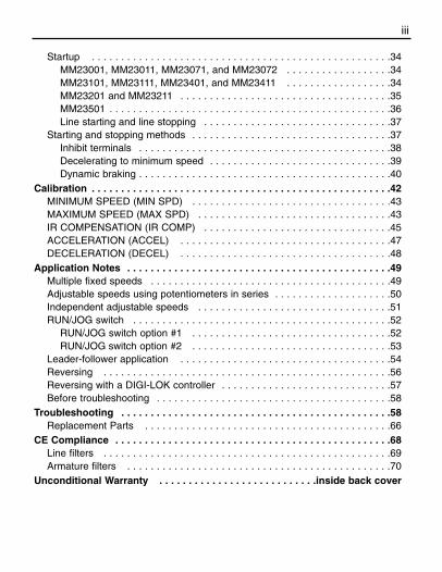
Startup . . . . . . . . . . . . . . . . . . . . . . . . . . . . . . . . . . . . . . . . . . . . . . . . . . .34MM23001, MM23011, MM23071, and MM23072 . . . . . . . . . . . . . . . . . .34MM23101, MM23111, MM23401, and MM23411 . . . . . . . . . . . . . . . . . .34MM23201 and MM23211 . . . . . . . . . . . . . . . . . . . . . . . . . . . . . . . . . . . .35MM23501 . . . . . . . . . . . . . . . . . . . . . . . . . . . . . . . . . . . . . . . . . . . . . . . .36Line starting and line stopping . . . . . . . . . . . . . . . . . . . . . . . . . . . . . . . .37
Starting and stopping methods . . . . . . . . . . . . . . . . . . . . . . . . . . . . . . . . . .37Inhibit terminals . . . . . . . . . . . . . . . . . . . . . . . . . . . . . . . . . . . . . . . . . . .38Decelerating to minimum speed . . . . . . . . . . . . . . . . . . . . . . . . . . . . . . .39Dynamic braking . . . . . . . . . . . . . . . . . . . . . . . . . . . . . . . . . . . . . . . . . . .40
Calibration . . . . . . . . . . . . . . . . . . . . . . . . . . . . . . . . . . . . . . . . . . . . . . . . . . .42MINIMUM SPEED (MIN SPD) . . . . . . . . . . . . . . . . . . . . . . . . . . . . . . . . . .43MAXIMUM SPEED (MAX SPD) . . . . . . . . . . . . . . . . . . . . . . . . . . . . . . . . .43IR COMPENSATION (IR COMP) . . . . . . . . . . . . . . . . . . . . . . . . . . . . . . . .45ACCELERATION (ACCEL) . . . . . . . . . . . . . . . . . . . . . . . . . . . . . . . . . . . .47DECELERATION (DECEL) . . . . . . . . . . . . . . . . . . . . . . . . . . . . . . . . . . . .48
Application Notes . . . . . . . . . . . . . . . . . . . . . . . . . . . . . . . . . . . . . . . . . . . . .49Multiple fixed speeds . . . . . . . . . . . . . . . . . . . . . . . . . . . . . . . . . . . . . . . . .49Adjustable speeds using potentiometers in series . . . . . . . . . . . . . . . . . . . .50Independent adjustable speeds . . . . . . . . . . . . . . . . . . . . . . . . . . . . . . . . .51RUN/JOG switch . . . . . . . . . . . . . . . . . . . . . . . . . . . . . . . . . . . . . . . . . . . .52
RUN/JOG switch option #1 . . . . . . . . . . . . . . . . . . . . . . . . . . . . . . . . . .52RUN/JOG switch option #2 . . . . . . . . . . . . . . . . . . . . . . . . . . . . . . . . . .53
Leader-follower application . . . . . . . . . . . . . . . . . . . . . . . . . . . . . . . . . . . .54Reversing . . . . . . . . . . . . . . . . . . . . . . . . . . . . . . . . . . . . . . . . . . . . . . . . .56Reversing with a DIGI-LOK controller . . . . . . . . . . . . . . . . . . . . . . . . . . . . .57Before troubleshooting . . . . . . . . . . . . . . . . . . . . . . . . . . . . . . . . . . . . . . . .58
Troubleshooting . . . . . . . . . . . . . . . . . . . . . . . . . . . . . . . . . . . . . . . . . . . . . .58Replacement Parts . . . . . . . . . . . . . . . . . . . . . . . . . . . . . . . . . . . . . . . . . .66
CE Compliance . . . . . . . . . . . . . . . . . . . . . . . . . . . . . . . . . . . . . . . . . . . . . . .68Line filters . . . . . . . . . . . . . . . . . . . . . . . . . . . . . . . . . . . . . . . . . . . . . . . . .69Armature filters . . . . . . . . . . . . . . . . . . . . . . . . . . . . . . . . . . . . . . . . . . . . .70
Unconditional Warranty . . . . . . . . . . . . . . . . . . . . . . . . . . .inside back cover
iii
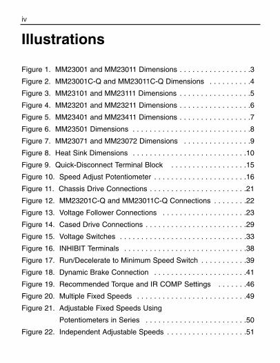
iv
Illustrations
Figure 1. MM23001 and MM23011 Dimensions . . . . . . . . . . . . . . . . .3
Figure 2. MM23001C-Q and MM23011C-Q Dimensions . . . . . . . . . .4
Figure 3. MM23101 and MM23111 Dimensions . . . . . . . . . . . . . . . . .5
Figure 4. MM23201 and MM23211 Dimensions . . . . . . . . . . . . . . . . .6
Figure 5. MM23401 and MM23411 Dimensions . . . . . . . . . . . . . . . . .7
Figure 6. MM23501 Dimensions . . . . . . . . . . . . . . . . . . . . . . . . . . . .8
Figure 7. MM23071 and MM23072 Dimensions . . . . . . . . . . . . . . . .9
Figure 8. Heat Sink Dimensions . . . . . . . . . . . . . . . . . . . . . . . . . . .10
Figure 9. Quick-Disconnect Terminal Block . . . . . . . . . . . . . . . . . .15
Figure 10. Speed Adjust Potentiometer . . . . . . . . . . . . . . . . . . . . . .16
Figure 11. Chassis Drive Connections . . . . . . . . . . . . . . . . . . . . . . .21
Figure 12. MM23201C-Q and MM23011C-Q Connections . . . . . . . .22
Figure 13. Voltage Follower Connections . . . . . . . . . . . . . . . . . . . .23
Figure 14. Cased Drive Connections . . . . . . . . . . . . . . . . . . . . . . . .29
Figure 15. Voltage Switches . . . . . . . . . . . . . . . . . . . . . . . . . . . . . .33
Figure 16. INHIBIT Terminals . . . . . . . . . . . . . . . . . . . . . . . . . . . . .38
Figure 17. Run/Decelerate to Minimum Speed Switch . . . . . . . . . . .39
Figure 18. Dynamic Brake Connection . . . . . . . . . . . . . . . . . . . . . .41
Figure 19. Recommended Torque and IR COMP Settings . . . . . . .46
Figure 20. Multiple Fixed Speeds . . . . . . . . . . . . . . . . . . . . . . . . . .49
Figure 21. Adjustable Fixed Speeds Using
Potentiometers in Series . . . . . . . . . . . . . . . . . . . . . . . .50
Figure 22. Independent Adjustable Speeds . . . . . . . . . . . . . . . . . . .51
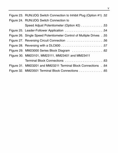
v
Figure 23. RUN/JOG Switch Connection to Inhibit Plug (Option #1) .52
Figure 24. RUN/JOG Switch Connection to
Speed Adjust Potentiometer (Option #2) . . . . . . . . . . . . .53
Figure 25. Leader-Follower Application . . . . . . . . . . . . . . . . . . . . . .54
Figure 26. Single Speed Potentiometer Control of Multiple Drives . .55
Figure 27. Reversing Circuit Connection . . . . . . . . . . . . . . . . . . . . .56
Figure 28. Reversing with a DLC600 . . . . . . . . . . . . . . . . . . . . . . . .57
FIgure 29. MM23000 Series Block Diagram . . . . . . . . . . . . . . . . . .62
FIgure 30. MM23101, MM23111, MM23401 and MM23411
Terminal Block Connections . . . . . . . . . . . . . . . . . . . . . .63
FIgure 31. MM23201 and MM23211 Terminal Block Connections . .64
Figure 32. MM23501 Terminal Block Connections . . . . . . . . . . . . . .65
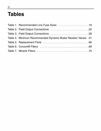
vi
Tables
Table 1. Recommended Line Fuse Sizes . . . . . . . . . . . . . . . . . . . .19
Table 2. Field Output Connections . . . . . . . . . . . . . . . . . . . . . . . . .20
Table 3. Field Output Connections . . . . . . . . . . . . . . . . . . . . . . . . .28
Table 4. Minimum Recommended Dynamic Brake Resistor Values .41
Table 5. Replacement Parts . . . . . . . . . . . . . . . . . . . . . . . . . . . . . .66
Table 6. Corcom® Filters . . . . . . . . . . . . . . . . . . . . . . . . . . . . . . . .69
Table 7. Minarik Filters . . . . . . . . . . . . . . . . . . . . . . . . . . . . . . . . . .70
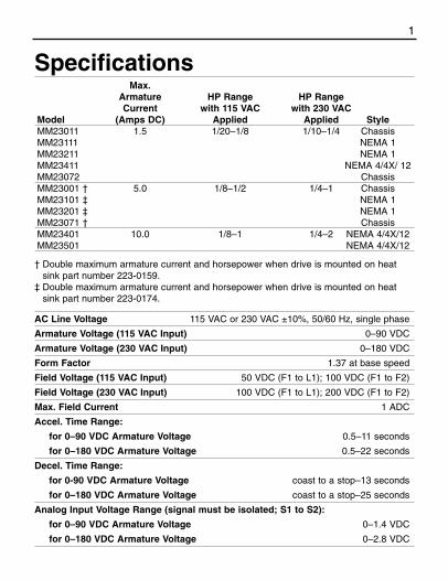
1
Specifications Max.
Armature HP Range HP RangeCurrent with 115 VAC with 230 VAC
Model (Amps DC) Applied Applied StyleMM23011 1.5 1/20–1/8 1/10–1/4 ChassisMM23111 NEMA 1MM23211 NEMA 1MM23411 NEMA 4/4X/ 12MM23072 ChassisMM23001 † 5.0 1/8–1/2 1/4–1 ChassisMM23101 ‡ NEMA 1MM23201 ‡ NEMA 1MM23071 † ChassisMM23401 10.0 1/8–1 1/4–2 NEMA 4/4X/12MM23501 NEMA 4/4X/12
† Double maximum armature current and horsepower when drive is mounted on heatsink part number 223-0159.
‡ Double maximum armature current and horsepower when drive is mounted on heatsink part number 223-0174.
AC Line Voltage 115 VAC or 230 VAC ±10%, 50/60 Hz, single phase
Armature Voltage (115 VAC Input) 0–90 VDC
Armature Voltage (230 VAC Input) 0–180 VDC
Form Factor 1.37 at base speed
Field Voltage (115 VAC Input) 50 VDC (F1 to L1); 100 VDC (F1 to F2)
Field Voltage (230 VAC Input) 100 VDC (F1 to L1); 200 VDC (F1 to F2)
Max. Field Current 1 ADC
Accel. Time Range:
for 0–90 VDC Armature Voltage 0.5–11 seconds
for 0–180 VDC Armature Voltage 0.5–22 seconds
Decel. Time Range:
for 0-90 VDC Armature Voltage coast to a stop–13 seconds
for 0–180 VDC Armature Voltage coast to a stop–25 seconds
Analog Input Voltage Range (signal must be isolated; S1 to S2):
for 0–90 VDC Armature Voltage 0–1.4 VDC
for 0–180 VDC Armature Voltage 0–2.8 VDC

2 Specifications
Input Impedance (S1 to S2) 100K ohms
Load Regulation 1% base speed or better
Vibration 0.5G max (0–50 Hz)
0.1G max (>50 Hz)
Safety Certification UL Recognized Component, file # E132235
CSA Certified Component, file # LR41380
CE Certificate of Compliance
Ambient Temp. Range (chassis drive) 10°C–55°C
Ambient Temp. Range (cased drive) 10°C–40°C
Suffix DefinitionsA: Basic driveC: Basic drive with current limit LED C-H: Basic drive with current limit header blockC-Q: Basic drive with current limit LED, power LED, and quick-
disconnect terminal block
Note:
• C suffix applies to all models except MM23071 and MM23072.
• C-H and C-Q suffixes apply only to models MM23001 and
MM23011.
• MM23071A and MM23072A drives include a current limit and
power LED; trimmer potentiometers (trimpots) are
perpendicular to the PC board.
Specifications (Continued)
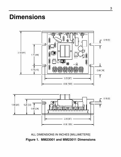
3
Dimensions
Figure 1. MM23001 and MM23011 Dimensions
ALL DIMENSIONS IN INCHES [MILLIMETERS]
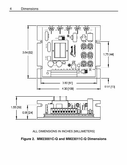
4 Dimensions
Figure 2. MM23001C-Q and MM23011C-Q Dimensions
ALL DIMENSIONS IN INCHES [MILLIMETERS]
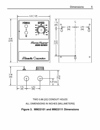
5Dimensions
TWO 0.88 [22] CONDUIT HOLES
Figure 3. MM23101 and MM23111 Dimensions
ALL DIMENSIONS IN INCHES [MILLIMETERS]
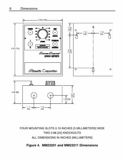
6
ALL DIMENSIONS IN INCHES [MILLIMETERS]
TWO 0.88 [22] KNOCKOUTS
FOUR MOUNTING SLOTS 0.19 INCHES [5 MILLIMETERS] WIDE
Dimensions
Figure 4. MM23201 and MM23211 Dimensions
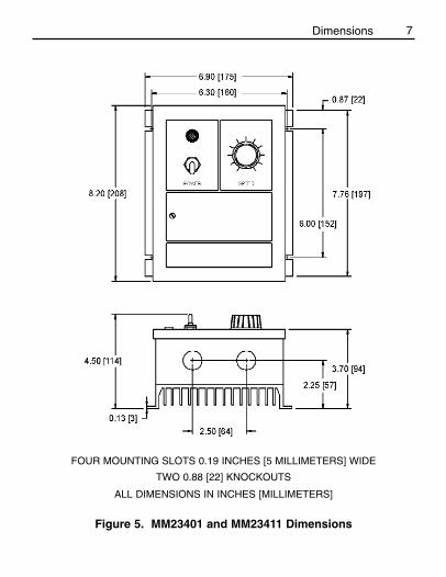
7Dimensions
Figure 5. MM23401 and MM23411 Dimensions
ALL DIMENSIONS IN INCHES [MILLIMETERS]
TWO 0.88 [22] KNOCKOUTS
FOUR MOUNTING SLOTS 0.19 INCHES [5 MILLIMETERS] WIDE
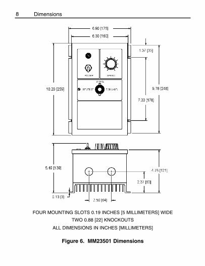
8 Dimensions
Figure 6. MM23501 Dimensions
ALL DIMENSIONS IN INCHES [MILLIMETERS]
TWO 0.88 [22] KNOCKOUTS
FOUR MOUNTING SLOTS 0.19 INCHES [5 MILLIMETERS] WIDE
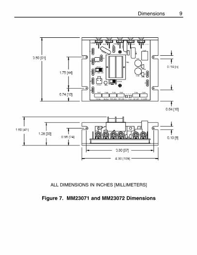
9
ALL DIMENSIONS IN INCHES [MILLIMETERS]
Figure 7. MM23071 and MM23072 Dimensions
Dimensions

10 Dimensions
PART NO. DIM “A” DIM “B” DIM “C” DIM “D” DIM “E”
223-0159 4.40 [112] 3.00 [76] 0.7 [18] 1.75 [44] 3.90 [100]
223-0174 7.78 [198] 6.00 [152] 0.89 [23] 6.00 [152] 5.35 [136]
Heat sinks sold separately.
Figure 8. Heat Sink Dimensions
MOUNTING SLOTS 0.19 X 0.34 [5 X 9]ALL DIMENSIONS IN INCHES [MILLIMETERS]

11
Chassis drivesMounting
• Drive components are sensitive to electrostatic fields. Avoidcontact with the circuit board directly. Hold drive by the chassisonly.
• Protect the drive from dirt, moisture, and accidental contact. • Provide sufficient room for access to the terminal block and
calibration trimpots.• Mount the drive away from other heat sources. Operate the drive
within the specified ambient operating temperature range.• Prevent loose connections by avoiding excessive vibration of the
drive.• Mount drive with its board in either a horizontal or vertical plane.
Six 0.19 inch (5 mm) wide slots in the chassis accept #8 panhead screws. Fasten either the large base or the narrow flangeof the chassis to the subplate.
• The chassis must be earth grounded. To ground the chassis, usea star washer beneath the head of at least one of the mountingscrews to penetrate the anodized chassis surface and to reachbare metal.
InstallationWarning
Do not install, rewire, or remove this control with inputpower applied. Doing so may cause fire or serious injury.Make sure you have read and understood the SafetyWarnings before attempting installation.

12 Installation
• Use 18-24 AWG wire for speed adjust potentiometer wiring. Use14–16 AWG wire for AC line (L1, L2) and motor (A1 and A2)wiring.
Wiring
Warning
Do not install, remove, or rewire this equipment with powerapplied. Failure to heed this warning may result in fire,explosion, or serious injury.
Circuit potentials are at 115 or 230 VAC above ground. Toprevent the risk of injury or fatality, avoid direct contact withthe printed circuit board or with circuit elements.
Do not disconnect any of the motor leads from the driveunless power is removed or the drive is disabled. Openingany one motor lead may destroy the drive.
13
Shielding guidelines
Warning
Under no circumstances should power and logic leads bebundled together. Induced voltage can cause unpredictablebehavior in any electronic device, including motor controls.
As a general rule, Minarik recommends shielding of all conductors.
If it is not practical to shield power conductors, Minarikrecommends shielding all logic-level leads. If shielding of logicleads is not practical, the user should twist all logic leads withthemselves to minimize induced noise.
It may be necessary to earth ground the shielded cable. If noise isproduced by devices other than the drive, ground the shield at thedrive end. If noise is generated by a device on the drive, groundthe shield at the end away from the drive. Do not ground both endsof the shield.
If the drive continues to pick up noise after grounding the shield, itmay be necessary to add AC line filtering devices, or to mount thedrive in a less noisy environment.
Logic wires from other input devices, such as motion controllersand PLL velocity controllers, must be separated from power lines inthe same manner as the logic I/O on this drive.
Installation

14 Installation
Heat sinking
Models MM23001 and MM23071 require an additional heat sink when the continuous armature current is above 5 ADC. UseMinarik part number 223-0159. All other chassis drives havesufficient heat sinking in their basic configurations. Use a thermallyconductive heat sink compound (such as Dow Corning® 340 HeatSink Compound) between the drive chassis and heat sink surfacefor optimum heat transfer.
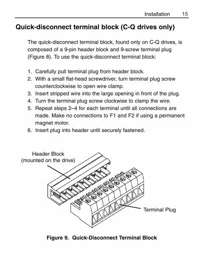
15
Quick-disconnect terminal block (C-Q drives only)
The quick-disconnect terminal block, found only on C-Q drives, iscomposed of a 9-pin header block and 9-screw terminal plug(Figure 8). To use the quick-disconnect terminal block:
1. Carefully pull terminal plug from header block.2. With a small flat-head screwdriver, turn terminal plug screw
counterclockwise to open wire clamp.3. Insert stripped wire into the large opening in front of the plug.4. Turn the terminal plug screw clockwise to clamp the wire.5. Repeat steps 2–4 for each terminal until all connections are
made. Make no connections to F1 and F2 if using a permanentmagnet motor.
6. Insert plug into header until securely fastened.
Figure 9. Quick-Disconnect Terminal Block
Header Block(mounted on the drive)
Terminal Plug
Installation

16 Installation
Speed adjust potentiometer
Mount the speed adjust potentiometer through a 0.38 in. (10 mm)hole with the hardware provided (Figure 9). Install the circularinsulating disk between the panel and the 10K ohm speed adjustpotentiometer.
Twist the speed adjust potentiometer wire to avoid picking upunwanted electrical noise. If speed adjust potentiometer wires arelonger than 18 in. (457 mm), use shielded cable. Keep speedadjust potentiometer wires separate from power leads (L1, L2, A1,A2).
Warning
Be sure that the potentiometer tabs do not make contact withthe potentiometer enclosure. Grounding the input will causedamage to the drive.
Figure 10. Speed Adjust Potentiometer

17
Power, fuse and motor connections
Connect the power input leads, an external line fuse and a DCmotor to TB501 on the drive’s printed circuit board (PCB) as shownin Figure 10, page 20.
MotorMinarik drives supply motor armature voltage from A1 and A2terminals. It is assumed throughout this manual that, when A1 ispositive with respect to A2 , the motor will rotate clockwise (CW)while looking at the output shaft protruding from the front of themotor. If this is opposite of the desired rotation, simply reverse thewiring of A1 and A2 with each other.
Chassis drive connections
Warning
Do not connect this equipment with power applied.Failure to heed this directive may result in fire or seriousinjury.
Minarik strongly recommends the installation of a masterpower switch in the voltage input line, as shown inFigure 10 (page 20). The switch contacts should be rated ata minimum of 200% of motor nameplate current and 250volts.
Installation

18 Installation
Connect a DC motor to PCB terminals A1 and A2 as shown inFigure 11, page 21. Ensure that the motor voltage rating isconsistent with the drive’s output voltage.
Power inputConnect the AC line power leads to TB501 terminals L1 and L2, orto a double-throw, single-pole master power switch(recommended). The switch should be rated at a minimum of 250volts and 200% of motor current. Refer to Figure 11, page 21.
Line fuse
Minarik drives require an external fuse for protection. Use fastacting fuses rated for 250 VAC or higher, and approximately 150%of the maximum armature current. Fuse only the HOT leg of theAC line that connects to L1 and leave L2 unfused when the AC linevoltage is 115 VAC. Table 1 (page 19) lists the recommended linefuse sizes.
Wire an external line fuse between the stop switch (if installed) andthe L1 terminal on terminal board TB501. An additional line fuseshould be installed on L2 if the input voltage is 230VAC. The linefuse(s) should be rated at 250 volts and 150 - 200% of maximummotor nameplate current.
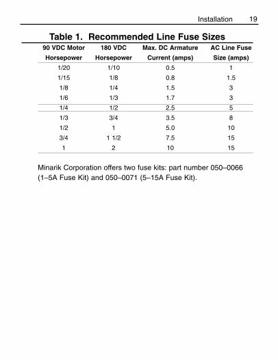
19Installation
Table 1. Recommended Line Fuse Sizes90 VDC Motor 180 VDC Max. DC Armature AC Line Fuse
Horsepower Horsepower Current (amps) Size (amps)
1/20 1/10 0.5 1
1/15 1/8 0.8 1.5
1/8 1/4 1.5 3
1/6 1/3 1.7 3
1/4 1/2 2.5 5
1/3 3/4 3.5 8
1/2 1 5.0 10
3/4 1 1/2 7.5 15
1 2 10 15
Minarik Corporation offers two fuse kits: part number 050–0066 (1–5A Fuse Kit) and 050–0071 (5–15A Fuse Kit).
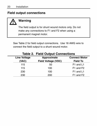
20 Installation
See Table 2 for field output connections. Use 18 AWG wire toconnect the field output to a shunt wound motor.
Table 2. Field Output ConnectionsLine Voltage Approximate Connect Motor
(VAC) Field Voltage (VDC) Field To115 50 F1 and L1115 100 F1 and F2230 100 F1 and L1230 200 F1 and F2
Warning
The field output is for shunt wound motors only. Do not make any connections to F1 and F2 when using apermanent magnet motor.
Field output connections
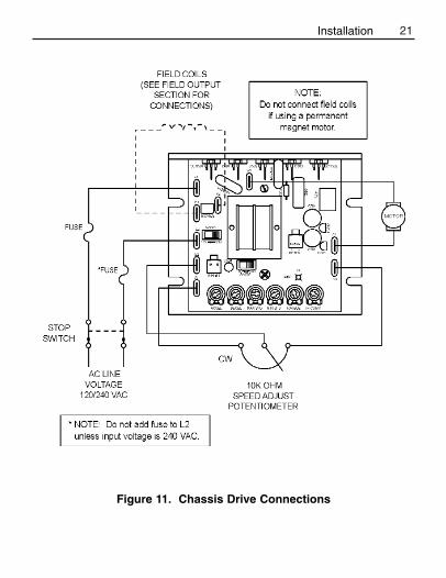
21
Figure 11. Chassis Drive Connections
Installation
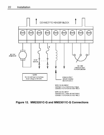
22
Figure 12. MM23201C-Q and MM23011C-Q Connections
Installation
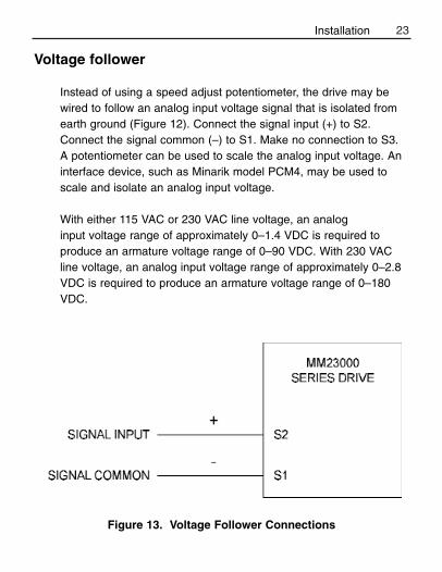
23
Voltage follower
Instead of using a speed adjust potentiometer, the drive may bewired to follow an analog input voltage signal that is isolated fromearth ground (Figure 12). Connect the signal input (+) to S2.Connect the signal common (–) to S1. Make no connection to S3.A potentiometer can be used to scale the analog input voltage. Aninterface device, such as Minarik model PCM4, may be used toscale and isolate an analog input voltage.
With either 115 VAC or 230 VAC line voltage, an analog input voltage range of approximately 0–1.4 VDC is required toproduce an armature voltage range of 0–90 VDC. With 230 VACline voltage, an analog input voltage range of approximately 0–2.8VDC is required to produce an armature voltage range of 0–180VDC.
Figure 13. Voltage Follower Connections
Installation

24 Installation
Mounting (NEMA 1 enclosures)
NEMA 1 cased drives come with 0.88 inch (22 mm) conduit holesat the bottom of the case. The units may be vertically wall mountedor horizontally bench mounted using the three keyholes on theback of the case.
1. For access to the keyholes and the terminal strip, remove thetwo screws from the front of the case by turning themcounterclockwise. Grasp the front cover and lift it straight out.
2. Install the mounting screws in the three keyholes.3. Install conduit hardware through the conduit holes at the bottom
of the case. Connect external wiring to the terminal block.4. Reinstall the front cover. Avoid pinching any wires between the
front cover and the case.5. Replace the two screws to the front cover. Turn the screws
clockwise to tighten.6. Set the POWER switch to the OFF position before applying the
AC line voltage.
Cased drives
Warning
Do not install, rewire, or remove this control with inputpower applied. Doing so may cause fire or serious injury.Make sure you have read and understood the SafetyWarnings before attempting installation.

25
Mounting (NEMA 12 enclosures)
NEMA 12 cased drives come with two 0.88 inch (22 mm) conduit knockout holes at the bottom of the case. The units may be vertically wall mounted using the four 0.19 inch (5 mm)slotted holes on the attached heat sink. For motor loads less than 5ADC, the drive may be bench mounted horizontally, or operatedwithout mounting.
1. Install the mounting screws.2. For access to the terminal strip, turn the slotted screw on the
front cover counterclockwise until it is free from the case. Theright side of the cover is hinged to the case. Pull the slottedscrew to open the case.
3. Carefully remove the conduit knockouts by tapping them intothe case and twisting them off with pliers.
4. Install conduit hardware through the 0.88 inch (22 mm)knockout holes. Connect external wiring to the terminal block.
5. Grasp the slotted screw and tilt the front cover back into place.Avoid pinching any wires between the front cover and the case.
6. Turn the slotted screw clockwise until tight to secure the frontcover.
7. Set the POWER switch to the OFF position before applying theAC line voltage.
Installation

26 Installation
Heat sinking
Models MM23101 and MM23201 require additional heat sinkingwhen the continuous armature current is above 5 ADC. UseMinarik part number 223-0174. All other cased drives havesufficient heat sinking in their basic configurations. Use a thermallyconductive heat sink compound (such as Dow Corning® 340 HeatSink Compound) between the back of the drive case and heat sinksurface for optimum heat transfer.
Line fusing
15 amp line fuses are preinstalled on the cased models MM23101,MM23201, MM23401, and MM23501. 3 amp line fuses arepreinstalled on the cased models MM23111, MM23211, andMM23411.
If the horsepower rating of the motor being used is less than themaximum horsepower rating of the drive, the line fuse may have tobe replaced with a lower rated one. Refer to the “RecommendedLine Fuse Sizes” table on page 18 to install a lower rated fuse.

27
Connections
Warning
Do not connect this equipment with power applied.Failure to heed this directive may result in fire or seriousinjury.
Minarik strongly recommends the installation of a masterpower switch in the voltage input line. The switchcontacts should be rated at a minimum of 200% of motornameplate current and 250 volts.
Power and motor connections
Connect the power input leads and a DC motor to TB501 as shownin Figure 13, page 28.
MotorMinarik drives supply motor voltage from A1 and A2 terminals. It isassumed throughout this manual that, when A1 is positive withrespect to A2 , the motor will rotate clockwise (CW) while lookingat the output shaft protruding from the front of the motor. If this isopposite of the desired rotation, simply reverse the wiring of A1and A2 with each other.
Connect a DC motor to PCB terminals A1 and A2 as shown inFigure 13. Ensure that the motor voltage rating is consistent withthe drive’s output voltage.
Installation
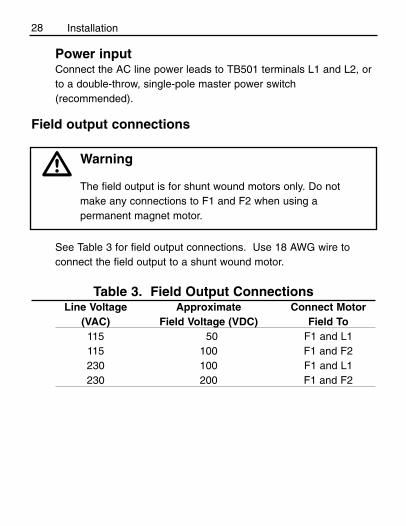
28 Installation
Power inputConnect the AC line power leads to TB501 terminals L1 and L2, orto a double-throw, single-pole master power switch(recommended).
Field output connections
Warning
The field output is for shunt wound motors only. Do not make any connections to F1 and F2 when using apermanent magnet motor.
See Table 3 for field output connections. Use 18 AWG wire toconnect the field output to a shunt wound motor.
Table 3. Field Output ConnectionsLine Voltage Approximate Connect Motor
(VAC) Field Voltage (VDC) Field To115 50 F1 and L1115 100 F1 and F2230 100 F1 and L1230 200 F1 and F2
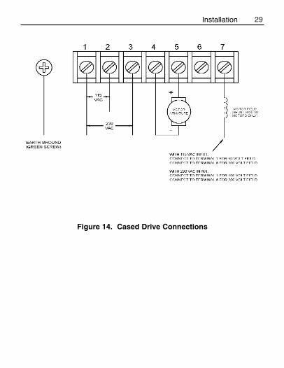
29
Figure 14. Cased Drive Connections
Installation

30 Installation
Current limit LED (C models only)
MM23000C series drives are equipped with a red current limit LED.The red current limit LED turns on whenever the drive reachescurrent limit and turns off whenever the drive is not in current limit(normal operation).
Current limit header block (C-H models only)
MM23000C-H series drives are equipped with a 2-pin current limitheader block. The current limit header block outputs approximatelya floating 5 VDC (5 mADC) signal whenever the drive reachescurrent limit. The signal may be used as an input to an externaldevice, such as an alarm or shut down circuit, that works when thedrive reaches current limit.
Meter header block (cased C models only)To supply power to external devices, the Meter header block can supply an unregulated +9 VDC (5 mA) signal when the motorand the power supply of the drive are fully loaded. More current isavailable with less motor loading. Meter can supply an unregulated+15V (10 mA) signal in typical applications.

31
MM23001C-Q, MM23071, and MM23072diagnostic LEDs
Models MM23001C-Q, MM23071, and MM23072 are equipped withtwo diagnostic LEDs:
Power (PWR): Lights whenever the AC line voltage is applied tothe drive.
Current Limit (CURR LIMIT or CL): Lights whenever the drivereaches current limit.
Installation
32
Operation
Before applying power
• Verify that no conductive material is present on the printed circuit
board.
• Ensure that the voltage select switches switches are properly set.
Warning
Change voltage switch settings only when the drive isdisconnected from AC line voltage. Make sure both switchesare set to their correct position. If the switches are improperlyset to a lower voltage position, the motor will not run at fullvoltage and may cause damage to the transformer. If theswitches are improperly set to a higher voltage position, themotor will overspeed, which may cause motor damage, orresult in bodily injury or loss of life.
Dangerous voltages exist on the drive when it is powered.BE ALERT. High voltages can cause serious or fatal injury.For your safety, use personal protective equipment (PPE)when operating this drive.
If the motor or drive does not perform as described,disconnect the AC line voltage immediately. Refer to theTroubleshooting section, page 57, for further assistance.
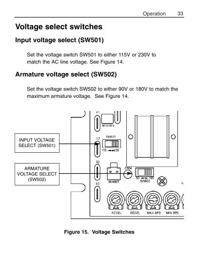
33Operation
Figure 15. Voltage Switches
Voltage select switches
Input voltage select (SW501)
Set the voltage switch SW501 to either 115V or 230V to match the AC line voltage. See Figure 14.
Armature voltage select (SW502)
Set the voltage switch SW502 to either 90V or 180V to match themaximum armature voltage. See Figure 14.
ARMATUREVOLTAGE SELECT
(SW502)
INPUT VOLTAGESELECT (SW501)

34 Operation
StartupMM23001, MM23011, MM23071, and MM23072
1. Turn the speed adjust potentiometer full counterclockwise(CCW).
2. Apply AC line voltage.3. Slowly advance the speed adjust potentiometer clockwise (CW).
The motor slowly accelerates as the potentiometer is turned CW.Continue until the desired speed is reached.
4. Remove AC line voltage from the drive to coast the motor to astop.
MM23101, MM23111, MM23401, and MM23411
1. Set the speed adjust potentiometer to “0” (full CCW).2. Apply AC line voltage.3. Set the POWER switch to the ON position.4. Slowly advance the speed adjust potentiometer clockwise
(CW). The motor slowly accelerates as the potentiometer isturned CW. Continue until the desired speed is reached.
5. Set the POWER switch to the OFF position to coast themotor to a stop.
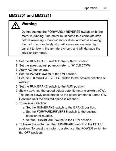
35
1. Set the RUN/BRAKE switch to the BRAKE position. 2. Set the speed adjust potentiometer to “0” (full CCW).3. Apply AC line voltage.4. Set the POWER switch to the ON position.5. Set the FORWARD/REVERSE switch to the desired direction of
rotation.6. Set the RUN/BRAKE switch to the RUN position.7. Slowly advance the speed adjust potentiometer clockwise (CW).
The motor slowly accelerates as the potentiometer is turned CW.Continue until the desired speed is reached.
8. To reverse direction:a. Set the RUN/BRAKE switch to the BRAKE position.b. Set the FORWARD/REVERSE switch to the desired
direction of rotation.c. Set the RUN/BRAKE switch to the RUN position.
9. To brake the motor, set the RUN/BRAKE switch to the BRAKEposition. To coast the motor to a stop, set the POWER switch tothe OFF position.
MM23201 and MM23211
Warning
Do not change the FORWARD / REVERSE switch while themotor is running. The motor must come to a complete stopbefore reversing. Changing motor direction before allowingthe motor to completely stop will cause excessively highcurrent to flow in the armature circuit, and will damage thedrive and/or motor.
Operation

36 Operation
1. Set the FORWARD/BRAKE/REVERSE switch to the BRAKEposition.
2. Set the speed adjust potentiometer to “0” (full CCW).3. Apply AC line voltage.4. Set the POWER switch to the ON position.5. Set the FORWARD/BRAKE/REVERSE switch to the desired
direction of rotation.7. Slowly advance the speed adjust potentiometer clockwise (CW).
The motor slowly accelerates as the potentiometer is turned CW.Continue until the desired speed is reached.
8. To reverse direction:a. Set the FORWARD/BRAKE/REVERSE switch to the
BRAKE position.b. After the motor comes to a complete stop, set the
FORWARD/BRAKE/REVERSE switch to the desireddirection of rotation.
9. To brake the motor, set the FORWARD/BRAKE/REVERSEswitch to the BRAKE position. To coast the motor to a stop, setthe POWER switch to the OFF position.
MM23501
Warning
The motor must come to a complete stop before reversing.Changing motor direction before allowing the motor tocompletely stop will cause excessively high current to flow inthe armature circuit, and will damage the drive and/or motor.
37
Starting and stopping methods
Line starting and line stopping
Line starting and line stopping (applying and removing AC linevoltage) is recommended for infrequent starting and stopping of adrive only. When AC line voltage is applied to the drive, the motoraccelerates to the speed set by the speed adjust potentiometer.When AC line voltage is removed, the motor coasts to a stop.
Warning
Decelerating to minimum speed, dynamic braking, or coastingto a stop is recommended for frequent starts and stops. Donot use any of these methods for emergency stopping. Theymay not stop a drive that is malfunctioning. Removing AC linepower (both L1 and L2) is the only acceptable method foremergency stopping.
For this reason, Minarik strongly recommends installingan emergency stop switch on both the L1 and L2 inputs(see connection diagrams on pages 20 & 21).
Operation
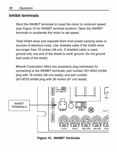
38 Operation
Inhibit terminals
Short the INHIBIT terminals to coast the motor to minimum speed(see Figure 15 for INHIBIT terminal location). Open the INHIBITterminals to accelerate the motor to set speed.
Twist inhibit wires and separate them from power-carrying wires orsources of electrical noise. Use shielded cable if the inhibit wiresare longer than 18 inches (46 cm). If shielded cable is used,ground only one end of the shield to earth ground. Do not groundboth ends of the shield.
Minarik Corporation offers two accessory plug harnesses forconnecting to the INHIBIT terminals: part number 201-0024 [inhibitplug with 18 inches (46 cm) leads]; and part number 201-0079 [inhibit plug with 36 inches (91 cm) leads].
Figure 16. INHIBIT Terminals
INHIBITTERMINALS
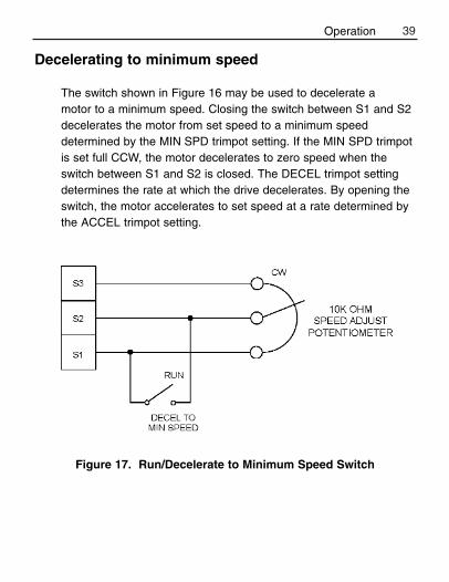
39
Decelerating to minimum speed
The switch shown in Figure 16 may be used to decelerate a motor to a minimum speed. Closing the switch between S1 and S2decelerates the motor from set speed to a minimum speeddetermined by the MIN SPD trimpot setting. If the MIN SPD trimpotis set full CCW, the motor decelerates to zero speed when theswitch between S1 and S2 is closed. The DECEL trimpot settingdetermines the rate at which the drive decelerates. By opening theswitch, the motor accelerates to set speed at a rate determined bythe ACCEL trimpot setting.
Figure 17. Run/Decelerate to Minimum Speed Switch
Operation
40 Operation
Dynamic braking
Warning
For frequent starts and stops, short the inhibit terminals,decelerate to a minimum speed, or apply a dynamic brake tothe motor. Do not use any of these methods for emergencystopping. They may not stop a drive that is malfunctioning.Removing AC line power (both L1 and L2) is the onlyacceptable method for emergency stopping.
Frequent starting and stopping can produce high torque. This may cause damage to motors, especially gearmotors that arenot properly sized for the application.
Dynamic braking may be used to rapidly stop a motor (Figure 17, page 40). For the RUN/BRAKE switch, use a two pole,two position switch rated for at least 125 VDC, 6 amps. For thedynamic brake resistor, use a 40 watt minimum, high power,wirewound resistor.
Sizing the dynamic brake resistor depends on load inertia, motorvoltage, and braking time. Use a lower-value, higher-wattagedynamic brake resistor to stop a motor more rapidly. Refer to Table4 (page 40) for recommended dynamic brake resistor sizes.
Note: Models MM23201, MM23211, and MM23501 incorporatedynamic braking in their designs.
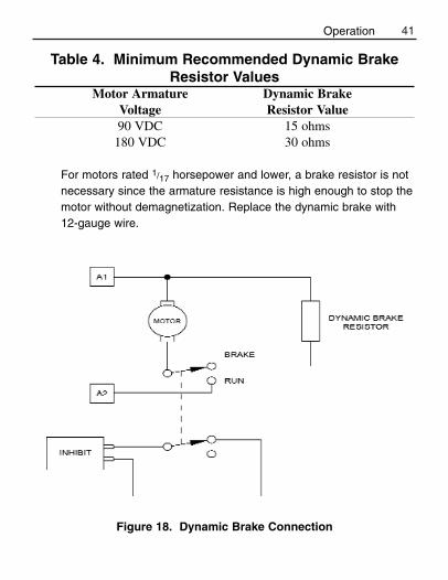
41
Table 4. Minimum Recommended Dynamic BrakeResistor Values
Motor Armature Dynamic BrakeVoltage Resistor Value90 VDC 15 ohms180 VDC 30 ohms
For motors rated 1/17 horsepower and lower, a brake resistor is notnecessary since the armature resistance is high enough to stop themotor without demagnetization. Replace the dynamic brake with12-gauge wire.
Figure 18. Dynamic Brake Connection
Operation

42
MM23000-series drives have user-adjustable trimpots. Each driveis factory calibrated to its maximum current rating. Readjust thecalibration trimpot settings to accommodate lower current ratedmotors.
All adjustments increase with CW rotation, and decrease with CCWrotation. Use a non-metallic screwdriver for calibration. Eachtrimpot is identified on the printed circuit board.
Calibration
Warning
Dangerous voltages exist on the drive when it is powered.When possible, disconnect the voltage input from the drivebefore adjusting the trimpots. If the trimpots must be adjustedwith power applied, use insulated tools and the appropriatepersonal protection equipment. BE ALERT. High voltages cancause serious or fatal injury.
43Calibration
MINIMUM SPEED (MIN SPD)
The MIN SPD trimpot establishes the motor speed obtained in
response to the minimum input signal. It is factory set for zero
speed.
To calibrate the MIN SPD pot, apply the minimum signal. Adjust the
MIN SPD trimpot until the motor runs at the desired speed or is just
at the threshold of rotation.
MAXIMUM SPEED (MAX SPD)
The MAX SPD setting determines the maximum motor speed when
the speed adjust potentiometer, or voltage input signal is set for
maximum forward speed. It is factory set for maximum rated motor
speed.
To calibrate MAX SPD:
1. Set the MAX SPD trimpot full CCW.
2. Set the speed adjust potentiometer or voltage input signal for
maximum forward speed.
3. Adjust MAX SPD until the desired maximum forward speed is
reached.
Note: Check the MIN SPD and MAX SPD adjustments afterrecalibrating to verify that the motor runs at the desired minimumand maximum speed.

TORQUE
44 Calibration
The TORQUE setting determines the maximum torque foraccelerating and driving the motor. To calibrate TORQUE, refer tothe recommended TORQUE settings in Figure 18 (page 45) or usthe following procedure:
1. With the power disconnected from the drive, connect a DC
ammeter in series with the armature.
2. Set the TORQUE trimpot to minimum (full CCW).
3. Set the speed adjust potentiometer to maximum speed
(full CW).
4. Carefully lock the motor armature. Be sure that the motor is
firmly mounted.
5. Apply line power. The motor should be stopped.
6. Slowly adjust the TORQUE trimpot CW until the armature
current is 150% of motor rated armature current.
7. Turn the speed adjust potentiometer CCW until the motor stops.
8. Remove line power.
9. Remove the stall from the motor.
10. Remove the ammeter in series with the motor armature if it is
no longer needed.
Warning
TORQUE should be set to 150% of motor nameplate currentrating. Continuous operation beyond this rating may damagethe motor. If you intend to operate beyond the rating, contactyour Minarik representative for assistance.
45
IR COMPENSATION (IR COMP)
The IR COMP trimpot setting determines the degree to whichmotor speed is held constant as the motor load changes. It isfactory set for optimum motor regulation.
Use the following procedure to recalibrate the IR COMP setting:1. Set the IR COMP trimpot to minimum (full CCW).2. Rotate the speed adjust potentiometer until the motor runs at
midspeed without load (for example, 900 RPM for an 1800 RPMmotor). A hand held tachometer may be used to measuremotor speed.
3. Load the motor armature to its full load armature current rating.The motor should slow down.
4. While keeping the load on the motor, rotate the IR COMPtrimpot until the motor runs at the speed measured in step 2. Ifthe motor oscillates (overcompensation), the IR COMP trimpotmay be set too high (CW). Turn the IR COMP trimpot CCW tostabilize the motor.
5. Unload the motor.
See Figure 18, for recommended IR COMP settings.
Calibration

46 Calibration
Figure 19. Recommended Torque and IR COMP Settings(actual settings may vary with each application)
47
ACCELERATION (ACCEL)
The ACCEL setting determines the time the motor takes to ramp to a higher speed. See Specifications on page 1 forapproximate acceleration times. ACCEL is factory set for thefastest acceleration time (full CCW).
To set the acceleration time:1. Set the speed adjust potentiometer full CCW. The motor
should run at minimum speed.2. Turn the speed adjust potentiometer full CW and measure
the time it takes the motor to go from minimum tomaximum speed.
3. If the time measured in step 2 is not the desired accelerationtime, turn the ACCEL trimpot CW for a slower accelerationtime, or CCW for a faster acceleration time. Repeat steps 1through 3 until the acceleration time is correct.
Calibration
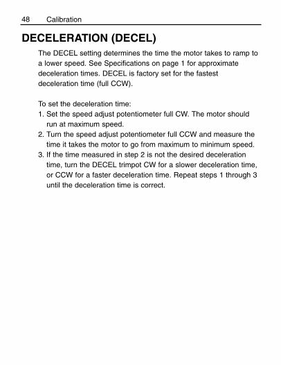
DECELERATION (DECEL)The DECEL setting determines the time the motor takes to ramp toa lower speed. See Specifications on page 1 for approximatedeceleration times. DECEL is factory set for the fastestdeceleration time (full CCW).
To set the deceleration time:1. Set the speed adjust potentiometer full CW. The motor should
run at maximum speed.2. Turn the speed adjust potentiometer full CCW and measure the
time it takes the motor to go from maximum to minimum speed.3. If the time measured in step 2 is not the desired deceleration
time, turn the DECEL trimpot CW for a slower deceleration time,or CCW for a faster deceleration time. Repeat steps 1 through 3until the deceleration time is correct.
48 Calibration
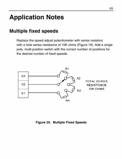
49
Multiple fixed speeds
Replace the speed adjust potentiometer with series resistors with a total series resistance of 10K ohms (Figure 19). Add a singlepole, multi-position switch with the correct number of positions forthe desired number of fixed speeds.
Application Notes
Figure 20. Multiple Fixed Speeds
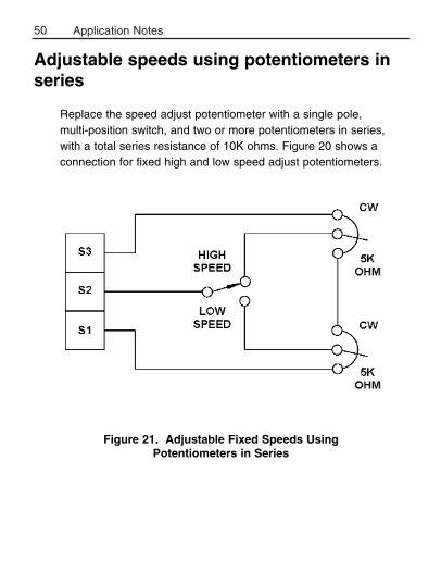
50 Application Notes
Adjustable speeds using potentiometers inseries
Replace the speed adjust potentiometer with a single pole, multi-position switch, and two or more potentiometers in series,with a total series resistance of 10K ohms. Figure 20 shows aconnection for fixed high and low speed adjust potentiometers.
Figure 21. Adjustable Fixed Speeds UsingPotentiometers in Series
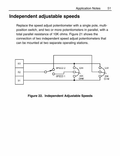
51
Independent adjustable speeds
Replace the speed adjust potentiometer with a single pole, multi-position switch, and two or more potentiometers in parallel, with atotal parallel resistance of 10K ohms. Figure 21 shows theconnection of two independent speed adjust potentiometers thatcan be mounted at two separate operating stations.
Figure 22. Independent Adjustable Speeds
Application Notes
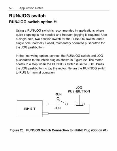
52 Application Notes
RUN/JOG switchRUN/JOG switch option #1
Using a RUN/JOG switch is recommended in applications wherequick stopping is not needed and frequent jogging is required. Usea single pole, two position switch for the RUN/JOG switch, and asingle pole, normally closed, momentary operated pushbutton forthe JOG pushbutton.
In the first wiring option, connect the RUN/JOG switch and JOGpushbutton to the inhibit plug as shown in Figure 22. The motorcoasts to a stop when the RUN/JOG switch is set to JOG. Pressthe JOG pushbutton to jog the motor. Return the RUN/JOG switchto RUN for normal operation.
Figure 23. RUN/JOG Switch Connection to Inhibit Plug (Option #1)
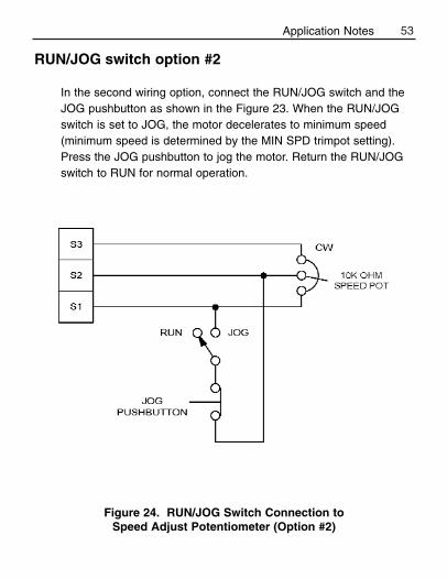
53
RUN/JOG switch option #2
In the second wiring option, connect the RUN/JOG switch and theJOG pushbutton as shown in the Figure 23. When the RUN/JOGswitch is set to JOG, the motor decelerates to minimum speed(minimum speed is determined by the MIN SPD trimpot setting).Press the JOG pushbutton to jog the motor. Return the RUN/JOGswitch to RUN for normal operation.
Figure 24. RUN/JOG Switch Connection toSpeed Adjust Potentiometer (Option #2)
Application Notes
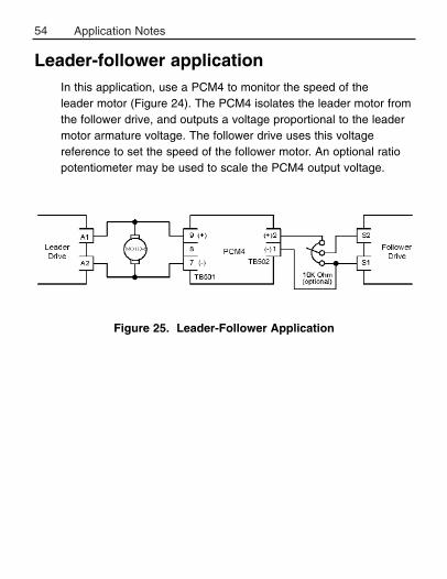
54 Application Notes
Leader-follower applicationIn this application, use a PCM4 to monitor the speed of the leader motor (Figure 24). The PCM4 isolates the leader motor fromthe follower drive, and outputs a voltage proportional to the leadermotor armature voltage. The follower drive uses this voltagereference to set the speed of the follower motor. An optional ratiopotentiometer may be used to scale the PCM4 output voltage.
Figure 25. Leader-Follower Application
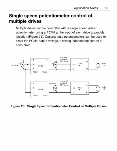
55
Single speed potentiometer control ofmultiple drives
Multiple drives can be controlled with a single speed adjustpotentiometer using a PCM4 at the input of each drive to provideisolation (Figure 25). Optional ratio potentiometers can be used toscale the PCM4 output voltage, allowing independent control ofeach drive.
Figure 26. Single Speed Potentiometer Control of Multiple Drives
Application Notes
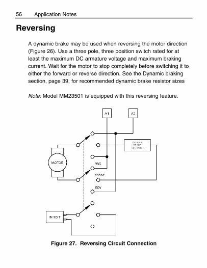
56
Reversing
A dynamic brake may be used when reversing the motor direction(Figure 26). Use a three pole, three position switch rated for atleast the maximum DC armature voltage and maximum brakingcurrent. Wait for the motor to stop completely before switching it toeither the forward or reverse direction. See the Dynamic brakingsection, page 39, for recommended dynamic brake resistor sizes
Note: Model MM23501 is equipped with this reversing feature.
Figure 27. Reversing Circuit Connection
Application Notes
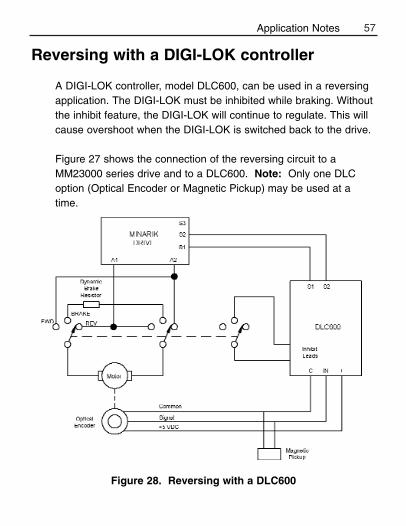
57
Reversing with a DIGI-LOK controller
A DIGI-LOK controller, model DLC600, can be used in a reversingapplication. The DIGI-LOK must be inhibited while braking. Withoutthe inhibit feature, the DIGI-LOK will continue to regulate. This willcause overshoot when the DIGI-LOK is switched back to the drive.
Figure 27 shows the connection of the reversing circuit to aMM23000 series drive and to a DLC600. Note: Only one DLCoption (Optical Encoder or Magnetic Pickup) may be used at atime.
Figure 28. Reversing with a DLC600
Application Notes

58
Troubleshooting
Before troubleshooting
Perform the following steps before starting any procedure in thissection:
1. Disconnect AC line voltage from the drive.2. Check the drive closely for damaged components.3. Check that no conductive or other foreign material has become
lodged on the printed circuit board.4. Verify that every connection is correct and in good condition.5. Verify that there are no short circuits or grounded connections.6. Check that the voltage selection switch settings match the AC
line and output voltages.7. Check that the drive’s rated armature and field outputs are
consistent with the motor ratings.
For additional assistance, contact your local Minarik Distributor, orthe factory direct at: Tel.: 1-800-MINARIK (646-2745) or Fax: 1-800-394-6334
Warning
Dangerous voltages exist on the drive when it is powered.When possible, disconnect the drive while troubleshooting.High voltages can cause serious or fatal injury.

59Troubleshooting
Line fuse blows. 1. Line fuse is the wrongsize.
2. Motor cable orarmature is shorted toground.
3. Nuisance trippingcaused by acombination of ambientconditions and high-current spikes (i.e.reversing).
1. Check that the linefuse is correct for themotor size.
2. Check motor cable andarmature for shorts.
3. Add a blower to coolthe drive components;decrease TORQUEsettings, or resizemotor and drive foractual load demand, orcheck for incorrectlyaligned mechanicalcomponents or “jams”.See page 43 forinformation onadjusting the TORQUEtrimpot.
Problem PossibleCauses
SuggestedSolutions

60 Troubleshooting
Line fuse does not blow,but the motor does notrun.
Motor does not stop when the speed adjustpotentiometer is full CCW.
Motor runs in the oppositedirection (non-reversingdrives).
1. Speed adjust pot orspeed referencevoltage is set to zerospeed.
2. INHIBIT terminals arejumpered.
3. S2 is shorted to S1.
4. Drive is in current limit.
5. Drive is not receivingAC line voltage.
6. Motor is not connected.
MIN SPD setting is toohigh.
Motor connections to A1and A2 are reversed.
1. Increase the speedadjust pot or speedreference voltageetting.
2. Remove jumper fromthe INHIBIT terminals.
3. Remove short.
4. Verify that motor is not jammed. IncreaseTORQUE setting ifthey are set too low.See page 43.
5. Apply AC line voltageto L1 and L2.
6. Connect motor to A1and A2.
Calibrate MIN SPD. Seepage 42.
Reverse connections toA1 and A2.
Problem PossibleCauses
SuggestedSolutions
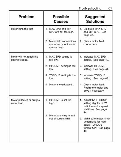
61
Motor runs too fast.
Motor will not reach thedesired speed.
Motor pulsates or surgesunder load.
1. MAX SPD and MINSPD are set too high.
2. Motor field connectionsare loose (shunt woundmotors only).
1. MAX SPD setting istoo low.
2. IR COMP setting is toolow.
3. TORQUE setting is toolow.
4. Motor is overloaded.
1. IR COMP is set toohigh.
2. Motor bouncing in andout of current limit.
1. Calibrate MAX SPDand MIN SPD. Seepage 42.
2. Check motor fieldconnections.
1. Increase MAX SPDsetting. See page 42.
2. Increase IR COMPsetting. See page 44.
3. Increase TORQUEsetting. See page 43.
4. Check motor load.Resize the motor anddrive if necessary.
1. Adjust the IR COMPsetting slightly CCWuntil the motor speedstabilizes. See page44.
2. Make sure motor is notundersized for load;adjust TORQUEtrimpot CW. See page43.
Problem PossibleCauses
SuggestedSolutions
Troubleshooting
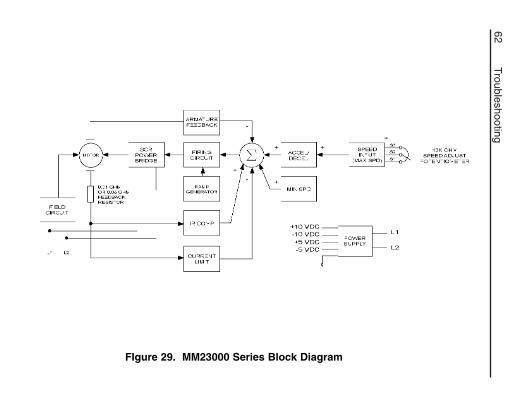
62Troubleshooting
FIgure 29. MM23000 Series Block Diagram
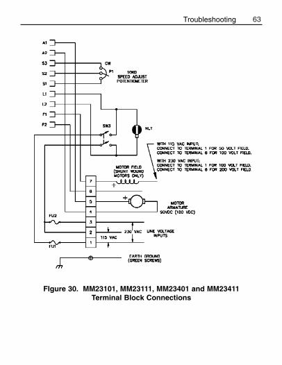
63
FIgure 30. MM23101, MM23111, MM23401 and MM23411 Terminal Block Connections
Troubleshooting
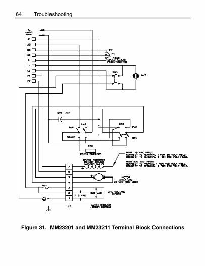
64 Troubleshooting
FIgure 31. MM23201 and MM23211 Terminal Block Connections
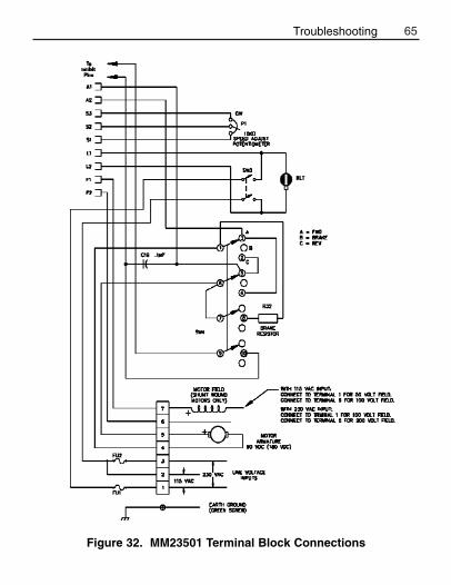
65
Figure 32. MM23501 Terminal Block Connections
Troubleshooting
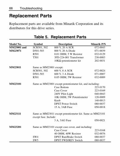
66 Troubleshooting
Replacement Parts
Replacement parts are available from Minarik Corporation and itsdistributors for this drive series.
Table 5. Replacement Parts
Model No. Symbol Description Minarik P/NMM23001 and SCR501, 502 800 V, 20 A SCR 072-0043MM23071 D501-503 800 V, 20 A Diode 071-0039
R501 0.01 OHM, 5 W Resistor 032-0129T501 3FD-224-001 Transformer 230-0083
10KΩ potentiometer kit 202-0031
MM23011 Same as MM23001 except:SCR501, 502 600 V, 8 A SCR 072-0024D501-503 600 V, 3 A Diode 071-0007R501 0.05 OHM, 5W Resistor 032-0089
MM23101 Same as MM23001 except potentiometer kit, and including:Case Bottom 223-0170Case Cover 223-0169240V Pilot Light 040-004310K OHM, 5W Potentiometer 120-0009Knob 140-0013DPST Power Switch 080-003715 A, 3AB Fuse 050-0018
MM23111 Same as MM23011 except potentiometer kit. Same as MM23101except fuse. Include:
3 A, 3AG Fuse 050-0021
MM23201 Same as MM23101 except case cover, and including:Case Cover 223-016840 OHM, 40W Resistor 032-0076
SW4 DPST Run/Brake Switch 080-0037SW5 DPST FWD/REV Switch 080-0037
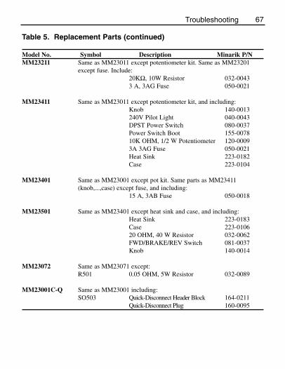
67
Table 5. Replacement Parts (continued)
Model No. Symbol Description Minarik P/NMM23211 Same as MM23011 except potentiometer kit. Same as MM23201
except fuse. Include:20KΩ, 10W Resistor 032-00433 A, 3AG Fuse 050-0021
MM23411 Same as MM23011 except potentiometer kit, and including:Knob 140-0013240V Pilot Light 040-0043DPST Power Switch 080-0037Power Switch Boot 155-007810K OHM, 1/2 W Potentiometer 120-00093A 3AG Fuse 050-0021Heat Sink 223-0182Case 223-0104
MM23401 Same as MM23001 except pot kit. Same parts as MM23411(knob,...,case) except fuse, and including:
15 A, 3AB Fuse 050-0018
MM23501 Same as MM23401 except heat sink and case, and including:Heat Sink 223-0183Case 223-010620 OHM, 40 W Resistor 032-0062FWD/BRAKE/REV Switch 081-0037Knob 140-0014
MM23072 Same as MM23071 except:R501 0.05 OHM, 5W Resistor 032-0089
MM23001C-Q Same as MM23001 including:SO503 Quick-Disconnect Header Block 164-0211
Quick-Disconnect Plug 160-0095
Troubleshooting

68
CE Compliance
Minarik Corporation hereby certifies that its MM23000 series driveshave been approved to bear the “CE” mark provided the conditionsof approval have been met by the end user.
The MM23000 series has been tested to the following testspecifications:
EN55011:1991 (emissions), andEN50082-1:1992 (immunity)
Compliance allows Minarik’s MM23000 series to bear the CE mark.
The end user, as described herein, falls into one of two categories:1. The Consumer will deploy a stand-alone unit as an
integral, yet external, portion of the machine beingoperated.
2. The Original Equipment Manufacturer (OEM) willimplement the product as a component of the machinebeing manufactured.
In addition to EMI/RFI safeguards inherent in the MM23000 series’design, external filtering is required.

69CE Compliance
Line filters
Minarik requires the Corcom® line filters listed below.
Table 6. Corcom® FiltersNameplate Current of Corcom® Filter
Motor Wired to the Drive Part Number0 to 4 amps 6VV1
4.1 to 13 amps 20VV1
If the exact line filter is not available, the specifications are asfollows:
L = (1.73 + 0.03) milliHenries.C = (0.27 + 0.54) microFarads (X); 0.0055 microFarads (Y).R = 330Kohms.Rated current: 1.4 times maximum DC motor current.Filter type: Balanced 2-section.
The line filters should be wired to the AC line within 0.25 meters ofthe drive. The ground connection from the line filter must be wiredto solid earth ground (resistance less than 500 ohms); not machineground. This is very important!
If the end-user is using a CE-approved motor, the correct line filterlisted above is all that is necessary to meet the EMC directiveslisted herein.

Armature filters
If the end-user is not using a CE-approved motor, a second filter on the armature must be used. It is Minarik’s CEXXMM. XX =rated current of the filter. Minarik Filters are listed below.
Table 7. Minarik FiltersNameplate Current of Minarik Filter
Motor Wired to the Drive Part Number0 to 4 amps CE4MM
4.1 to 13 amps CE20MM
The filters listed above are Real-Pole Balanced-Pi 3-pole filters. If the exact filter is not available, the specifications are as follows:
L & L1 = 2 * (0.8) milliHenries.C & C1 = 2 * (0.1) microFarads @ 400W VDC.Rin = 0.1 ohm; Rout = 1.2 ohm.
The filters listed above must be wired to the DC output of the drive,as close to the drive as possible.
70 CE Compliance

The end user must use the filters listed in this section to complywith CE. The OEM may choose to provide alternative filtering thatencompasses the Minarik drive and other electronics within thesame panel.
The OEM has this liberty because CE is a machinery directive.Whether or not every component in the OEM’s machinery meetsCE, the OEM must still submit his machine for CE approval.
Thus, no component must necessarily meet CE within the machine,as long as the OEM takes the necessary steps to guarantee themachine does meet CE. By the same token, even if everycomponent in the OEM’s machine does meet CE, the machine willnot necessarily meet CE as a machine.
Using CE-approved wiring practices (like proper shielding) and thefilters listed in this section help the drive meet EN55011 (1991emissions standard) and EN50082-1 (1992 immunity standard).
71CE Compliance

NOTES
72

NOTES
73

NOTES
74

Unconditional Warranty
A. Warranty - Minarik Corporation (referred to as “the Corporation”) warrants that itsproducts will be free from defects in workmanship and material for twelve (12) months or3,000 hours, whichever comes first, from date of manufacture thereof. Within this warrantyperiod, the Corporation will repair or replace, at its sole discretion, such products that arereturned to Minarik Corporation, 901 East Thompson Avenue, Glendale, CA 91201-2011USA.
This warranty applies only to standard catalog products, and does not apply to specials. Anyreturns for special controls will be evaluated on a case-by-case basis. The Corporation isnot responsible for removal, installation, or any other incidental expenses incurred inshipping the product to and from the repair point.
B. Disclaimer - The provisions of Paragraph A are the Corporation’s sole obligation andexclude all other warranties of merchantability for use, express or implied. The Corporationfurther disclaims any responsibility whatsoever to the customer or to any other person forinjury to the person or damage or loss of property of value caused by any product that hasbeen subject to misuse, negligence, or accident, or misapplied or modified by unauthorizedpersons or improperly installed.
C. Limitations of Liability - In the event of any claim for breech of any of the Corporation’sobligations, whether express or implied, and particularly of any other claim or breech ofwarranty contained in Paragraph A, or of any other warranties, express or implied, or claimof liability that might, despite Paragraph B, be decided against the Corporation by lawfulauthority, the Corporation shall under no circumstances be liable for any consequentialdamages, losses, or expense arising in connection with the use of, or inability to use, theCorporation’s product for any purpose whatsoever.
An adjustment made under warranty does not void the warranty, nor does it imply anextension of the original 12-month warranty period. Products serviced and/or parts replacedon a no-charge basis during the warranty period carry the unexpired portion of the originalwarranty only.
If for any reason any of the foregoing provisions shall be ineffective, the Corporation’s liabilityfor damages arising out of its manufacture or sale of equipment, or use thereof, whethersuch liability is based on warranty, contract, negligence, strict liability in tort, or otherwise,shall not in any event exceed the full purchase price of such equipment.
Any action against the Corporation based upon any liability or obligation arising hereunderor under any law applicable to the sale of equipment or the use thereof, must be commencedwithin one year after the cause of such action arises.

901 E Thompson AvenueGlendale, CA 91201-2011Tel.: 1-800-MINARIK (646-2745)
Fax: 1-800-394-6334www.minarikcorp.com
Document number 250–0091, Revision 5Printed in the U.S.A – 10/01
North America $12.00, Outside North America $15.00
DLC600
XP Series(AC or DC Input)
MM-PCM SeriesPCM20000 Series
Other drives from Minarik Corporation: