operating and user manual - adimec.com · genapi genicam application programming interface genicam...
TRANSCRIPT
OPERATING AND USER MANUAL ________________________________________________________________________________________________________________
Operating and user manual N-5A100 CoaXPress rev1.0

OPERATING AND USER MANUAL N-5A100 ________________________________________________________________________________________________________________
_________________________________________________________________________________________ Adimec 2
ABOUT ADIMEC
Adimec designs, manufactures, and markets high performance industrial cameras for equipment manufacturers in:
Machine Vision
Healthcare
Global Security Our high resolution cameras offer a unique combination of excellence in image quality, speed, and reliability. With optimized functionality for the needs of specific applications, Adimec cameras exceed general purpose. Adimec is a reliable partner with a focus on establishing long term relationships through a worldwide network of highly qualified engineers. Adimec aligns its roadmap in close cooperation with industry leaders and monitors the market for the latest technology to continuously provide innovative cameras that enhance our customers' competitiveness. With our capabilities, modular designs, process control and commitment to partnership, we can tailor to the exact solution required in a short time to market and with low risk.
Adimec Advanced Image Systems B.V.
PO Box 7909
5605 SH Eindhoven
The Netherlands
Phone: +31 (0)40 235 3900
E-mail: [email protected]
Adimec Japan
2-10-3-103, Narimasu, Itabashi-Ku
175-0094 Tokyo, Japan
Phone: +81 (3) 5968 8377
Fax: +81 (3) 5968 8388
E-mail: [email protected]
Adimec Electronic Imaging, Inc.
130 New Boston Street, Suite 204
Woburn, MA 01801, USA
Phone: +1 (781) 279 0770
Fax: +1 (781) 279 0571
E-mail: [email protected]
Adimec Asia/Pacific 228 Changi Road #03-07 ICON @ Changi Singapore 419741 Phone: +65 6334 1236 Fax: +65 6334 1436 E-mail: [email protected]

OPERATING AND USER MANUAL N-5A100 ________________________________________________________________________________________________________________
_________________________________________________________________________________________ Adimec 3
TABLE OF CONTENTS
ABOUT ADIMEC .................................................................................................................................................... 2
TABLE OF CONTENTS ......................................................................................................................................... 3
1 INTRODUCTION .............................................................................................................................................. 4
1.1 ABOUT THIS MANUAL .......................................................................................................................... 4 1.2 LIST OF FREQUENTLY USED ABBREVIATIONS ........................................................................................ 4 1.3 WASTE ELECTRICAL AND ELECTRONIC EQUIPMENT .............................................................................. 5 1.4 LIABILITY ............................................................................................................................................ 5
2 SAFETY PRECAUTIONS ................................................................................................................................ 6
2.1 CLEANING OF THE CMOS SENSOR ...................................................................................................... 6 2.2 CAMERA HOUSING .............................................................................................................................. 7
3 QUICK START GUIDE .................................................................................................................................... 9
4 INTERFACES ................................................................................................................................................ 10
4.1 MECHANICAL INTERFACE .................................................................................................................. 10 4.2 ELECTRICAL INTERFACES .................................................................................................................. 10 4.3 OPTICAL INTERFACE ......................................................................................................................... 13
5 TIMING ........................................................................................................................................................... 14
5.1 FRAME RATE .................................................................................................................................... 14 5.2 OPERATIONAL TIMING ....................................................................................................................... 15
6 CONTROL OF THE CAMERA ...................................................................................................................... 17
7 CAMERA FEATURES ................................................................................................................................... 19
7.1 FUNCTIONAL DIAGRAM ...................................................................................................................... 19 7.2 FEATURE DESCRIPTION STRUCTURE .................................................................................................. 21 7.3 BOOTSTRAP COAXPRESS ................................................................................................................ 22 7.4 DEVICE CONTROL ............................................................................................................................ 24 7.5 IMAGE FORMAT CONTROL ................................................................................................................. 25 7.6 ACQUISITION CONTROL .................................................................................................................... 30 7.7 ANALOG CONTROL ........................................................................................................................... 32 7.8 FACTORY ......................................................................................................................................... 33 7.9 LUT CONTROL ................................................................................................................................. 34 7.10 TRANSPORT LAYER CONTROL ........................................................................................................... 35 7.11 DEFECT PIXEL .................................................................................................................................. 35 7.12 DARK FIELD ..................................................................................................................................... 37 7.13 BRIGHT FIELD .................................................................................................................................. 38 7.14 BAND ............................................................................................................................................... 40 7.15 SENSOR .......................................................................................................................................... 42 7.16 USER SET CONTROL ........................................................................................................................ 42
APPENDIX A: CMOS SENSOR CLEANING INSTRUCTIONS .......................................................................... 44
OPERATING AND USER MANUAL N-5A100 ________________________________________________________________________________________________________________
_________________________________________________________________________________________ Adimec 4
1 INTRODUCTION
1.1 About this manual
This manual describes the N-5A100 CoaXPress camera:
Product name Product code
N-5A100-Gm/CXP-6.1.1 193101
Practical tips or notes are indicated by the “NOTE:” sign.
1.2 List of frequently used abbreviations
Abbreviation Full expression
CMOS Complementary Metal Oxide Semiconductor
CRC Cyclic Redundancy Check
CXP CoaXPress
ESD Electro-Static Discharge
GenAPI GenICam Application Programming Interface
GenICam Generic Interface for Cameras
GUI Graphical User Interface
LED Light Emitting Diode
LUT Look-up Table
PoCXP Power over CoaXPress
SFNC Standard Features Naming Convention
WEEE Waste Electrical and Electronic Equipment
XML Extensible Markup Language
OPERATING AND USER MANUAL N-5A100 ________________________________________________________________________________________________________________
_________________________________________________________________________________________ Adimec 5
1.3 Waste Electrical and Electronic Equipment
With regard to waste electrical and electronic equipment (WEEE), Adimec wishes to follow the Directive 2002/96/EC of the European Parliament and of the Council. The purpose of this Directive is, as a first priority, the prevention of waste electrical and electronic equipment (WEEE), and in addition, the reuse, recycling and other forms of recovery of such wastes so as to reduce the disposal of waste. It also seeks to improve the environmental performance of all operators involved in the life cycle of electrical and electronic equipment, e.g. producers, distributors and consumers and in particular those operators directly involved in the treatment of waste electrical and electronic equipment. Separate collection for electronic equipment in your area is recommended in order to minimize the disposal of WEEE as unsorted municipal waste and to achieve a high level of separate collection of WEEE.
1.4 Liability
Adimec prepares this manual with the greatest care. Please inform Adimec of any inaccuracies or omissions. Adimec Advanced Image Systems B.V. cannot be held responsible for any technical or typographical errors and reserves the right to make changes to the product and manuals without prior notice. Adimec Advanced Image Systems B.V. makes no warranty of any kind with regard to the material contained within this document, including, but not limited to, the implied warranties of merchantability and fitness for a particular purpose. Adimec Advanced Image Systems B.V. shall not be liable or responsible for incidental or consequential damages in connection with the furnishing, performance or use of this material. All rights reserved. No part of this document may be reproduced, stored in a database or retrieval system, or published in any other form or way, electronically, mechanically, by print, photo print, microfilm or any other means without prior written permission from the publisher. Layout, composing and editorial staff: Adimec Advanced Image Systems B.V. Illustrations: Adimec Advanced Image Systems B.V. All correspondence regarding copyrights and translations should be directed to: Adimec Advanced Image Systems B.V. PO Box 7909 5605 SH Eindhoven The Netherlands Tel: +31 (40) 2353920
E-mail: [email protected]
URL: www.adimec.com © Copyright 2016 Adimec Advanced Image Systems B.V. Eindhoven, The Netherlands.
OPERATING AND USER MANUAL N-5A100 ________________________________________________________________________________________________________________
_________________________________________________________________________________________ Adimec 6
2 SAFETY PRECAUTIONS
NOTE: A CMOS sensor camera is a sensitive device. Please read the following precautions carefully before continuing unpacking or operating the camera.
NOTE: It is advised to unpack and handle the camera in a clean ESD protected working area. NOTE: It is advised to read the whole manual before using the camera. NOTE: Always keep the sensor cap in place as long as no lens is attached. NOTE: Remove the sensor cap just before the lens is screwed on the camera. It is advised to perform this
operation in a clean room or clean bench. NOTE: Never touch the CMOS sensor surface. The cover glass is easily damaged and the CMOS sensor can
be damaged by ESD. NOTE: In case the camera is used as a subsystem, it is advised to include the text of this chapter in the
assembly documents of the main system.
2.1 Cleaning of the CMOS sensor
The cleaning of a CMOS sensor is a difficult task with a high risk on permanent damage to the camera. NOTE: It is advised to prevent cleaning the CMOS sensor as much as possible. NOTE: Damage of the CMOS sensor due to scratches on the cover glass or ESD is not covered by warranty! All cameras are checked for cleanliness in our factory before shipment. Proper handling instructions during system assembly can prevent the CMOS sensor from getting contaminated. Should cleaning of the CMOS sensor be necessary, please refer to Appendix A: CMOS Sensor cleaning instructions.

OPERATING AND USER MANUAL N-5A100 ________________________________________________________________________________________________________________
_________________________________________________________________________________________ Adimec 7
2.2 Camera housing
Thermal interfacing The act ual housing temperature achieved depends on the thermal configuration of the camera and the system in the end-user application. Provisions as to guarantee maximum housing temperature are therefore a responsibility of the end-user. NOTE: The housing temperature should not exceed +55° Celcius. NOTE: Create airflow over the camera e.g. by using a fan. NOTE: Mount the thermal interface of the camera on a substantial (preferably metal) body that can act as a heat sink. The thermal interface of the camera is the top and bottom side of the camera housing as shown in the below figure.
Cleaning The camera should NEVER be immersed in water or any other fluid. For cleaning, only use a light moist tissue. Connector Take care of the connector during handling of the camera. The connector should not be damaged. Prevent the entry of foreign objects or dirt into the connector, as this will result in unreliable operation or damage. Mounting screws M3 screws should be used with a maximum screw depth of 5 mm. The recommended tightening torque is 108 cNm. Take notice of the maximum length of the screws that may be used for mounting the camera. Using screws too long can cause damage to the camera.
2.3 Camera repair and Warranty Repair, modification and replacement of parts shall be done only by Adimec to maintain compliance with the directive 89/336/EEC electromagnetic compatibility, directive 72/23/EEC low voltage directive and the international standards. For repair and warranty claims contact your local dealer or the business offices in your region. The minimum information we need to know for a repair request or warranty claim are the camera serial number and a detailed failure description. In case the camera needs to be returned to investigate the repair options or grant your warranty claim you will receive a Return Material Authorization (RMA) number. Please use this RMA-number to ship the camera to Adimec. Cameras without RMA number will be rejected.
OPERATING AND USER MANUAL N-5A100 ________________________________________________________________________________________________________________
_________________________________________________________________________________________ Adimec 8
Once the camera is arrived at Adimec the camera will be investigated to proof possible repair or grant your warranty claim. In case of repair the repair costs will be quoted. After your approval of the repair cost camera will be repaired and returned.
OPERATING AND USER MANUAL N-5A100 ________________________________________________________________________________________________________________
_________________________________________________________________________________________ Adimec 9
3 QUICK START GUIDE
The procedure to obtain the first images from the camera depends to some extend on the frame grabber brand or type you use. A general quick start guide is therefore difficult to provide. NOTE: The Adimec support department has a couple of frame grabbers available. Inform at
[email protected] which frame grabber specific quick install guides are available or can be created.
The general steps to collect your first images are:
1. Mount a lens on the camera.
2. Connect the CXP cable to the camera.
3. Connect the CXP cable to the frame grabber.
4. Start the PC.
5. Go through the frame grabber specific procedure to configure your frame grabber. Some frame grabbers will automatically identify the camera while for others the right configuration file has to be loaded.
6. Use the capture software supplied by your frame grabber manufacturer to start acquiring images.
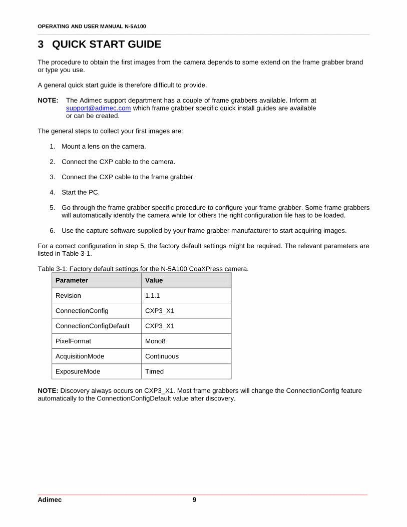
For a correct configuration in step 5, the factory default settings might be required. The relevant parameters are listed in Table 3-1.
Table 3-1: Factory default settings for the N-5A100 CoaXPress camera.
Parameter Value
Revision 1.1.1
ConnectionConfig CXP3_X1
ConnectionConfigDefault CXP3_X1
PixelFormat Mono8
AcquisitionMode Continuous
ExposureMode Timed
NOTE: Discovery always occurs on CXP3_X1. Most frame grabbers will change the ConnectionConfig feature automatically to the ConnectionConfigDefault value after discovery.

OPERATING AND USER MANUAL N-5A100 ________________________________________________________________________________________________________________
_________________________________________________________________________________________ Adimec 10
4 INTERFACES
In this chapter the mechanical, electrical, and optical interface are described in detail.
4.1 Mechanical interface
For the mechanical interface please refer to the mechanical outline drawing.
4.2 Electrical interfaces
Only one electrical interface, CoaXPress, is available. The interface connector can be found on the back side of the camera, see Figure 4-1. The type of the connector is explained in Table 4-1.
Figure 4-1: Electrical interface, a BNC connector on the back of the camera. Table 4-1: A description of the connector on the back side of the camera.
Connector Description Connector type (camera) Mating connector (cable)
1 CXP connection 0 BNC BNC
4.2.1 Power and CoaXPress connector The CoaXPress interface supports communication in two directions. Power, control data and trigger signals are transferred from the frame grabber to the camera and video data is transferred from the camera to the frame grabber. The function of the connector is listed in Table 4-2. The CXP configurations that are supported by the camera are listed in Table 4-3. Table 4-2: Functionality per CXP connection
CXP connector Interface functions
0 Video, power, control, triggering (Master connection)
OPERATING AND USER MANUAL N-5A100 ________________________________________________________________________________________________________________
_________________________________________________________________________________________ Adimec 11
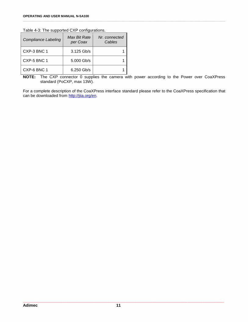
Table 4-3: The supported CXP configurations.
Compliance Labeling Max Bit Rate
per Coax Nr. connected
Cables
CXP-3 BNC 1 3.125 Gb/s 1
CXP-5 BNC 1 5.000 Gb/s 1
CXP-6 BNC 1 6.250 Gb/s 1
NOTE: The CXP connector 0 supplies the camera with power according to the Power over CoaXPress standard (PoCXP, max 13W).
For a complete description of the CoaXPress interface standard please refer to the CoaXPress specification that can be downloaded from http://jiia.org/en.
OPERATING AND USER MANUAL N-5A100 ________________________________________________________________________________________________________________
_________________________________________________________________________________________ Adimec 12
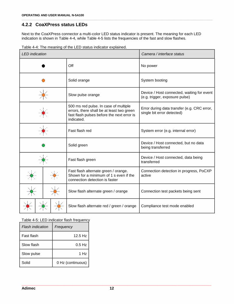
4.2.2 CoaXPress status LEDs Next to the CoaXPress connector a multi-color LED status indicator is present. The meaning for each LED indication is shown in Table 4-4, while Table 4-5 lists the frequencies of the fast and slow flashes. Table 4-4: The meaning of the LED status indicator explained.
LED indication Camera / interface status
Off No power
Solid orange System booting
Slow pulse orange
Device / Host connected, waiting for event (e.g. trigger, exposure pulse)
500 ms red pulse. In case of multiple errors, there shall be at least two green fast flash pulses before the next error is indicated.
Error during data transfer (e.g. CRC error, single bit error detected)
Fast flash red System error (e.g. internal error)
Solid green
Device / Host connected, but no data being transferred
Fast flash green
Device / Host connected, data being transferred
Fast flash alternate green / orange. Shown for a minimum of 1 s even if the connection detection is faster
Connection detection in progress, PoCXP active
Slow flash alternate green / orange Connection test packets being sent
Slow flash alternate red / green / orange Compliance test mode enabled
Table 4-5: LED indicator flash frequency
Flash indication Frequency
Fast flash 12.5 Hz
Slow flash 0.5 Hz
Slow pulse 1 Hz
Solid 0 Hz (continuous)
OPERATING AND USER MANUAL N-5A100 ________________________________________________________________________________________________________________
_________________________________________________________________________________________ Adimec 13
4.2.3 Programming over CoaXPress The CoaXPress interface can be used for firmware uploads to the camera. The availability of this feature is dependent on the frame grabber manufacturer and the SDK version that is being used. Please inform at [email protected] if this feature is available for your system configuration.
4.2.4 Grounding scheme On all cameras, the mechanical ground is interconnected with the power ground.
4.3 Optical interface
The N-5A100 camera is supplied with a fixed C-mount lens mount.
OPERATING AND USER MANUAL N-5A100 ________________________________________________________________________________________________________________
_________________________________________________________________________________________ Adimec 14
5 TIMING
5.1 Frame rate
The following camera features could influence the maximum frame rate:
Camera feature Description CXP group
ConnectionConfig The number of CXP links and the CXP link speed
BootstrapCoaXPress
StreamPacketSizeMax The packet size in bytes BootstrapCoaXPress
PixelFormat The pixel format in bit per pixel ImageFormatControl
Width and Height The region of interest ImageFormatControl
BinningHorizontal & BinningVertical
The number of binned pixels in the horizontal and vertical direction
ImageFormatControl
InterfaceUtilization The interface utilization factor in percent AcquisitionControl
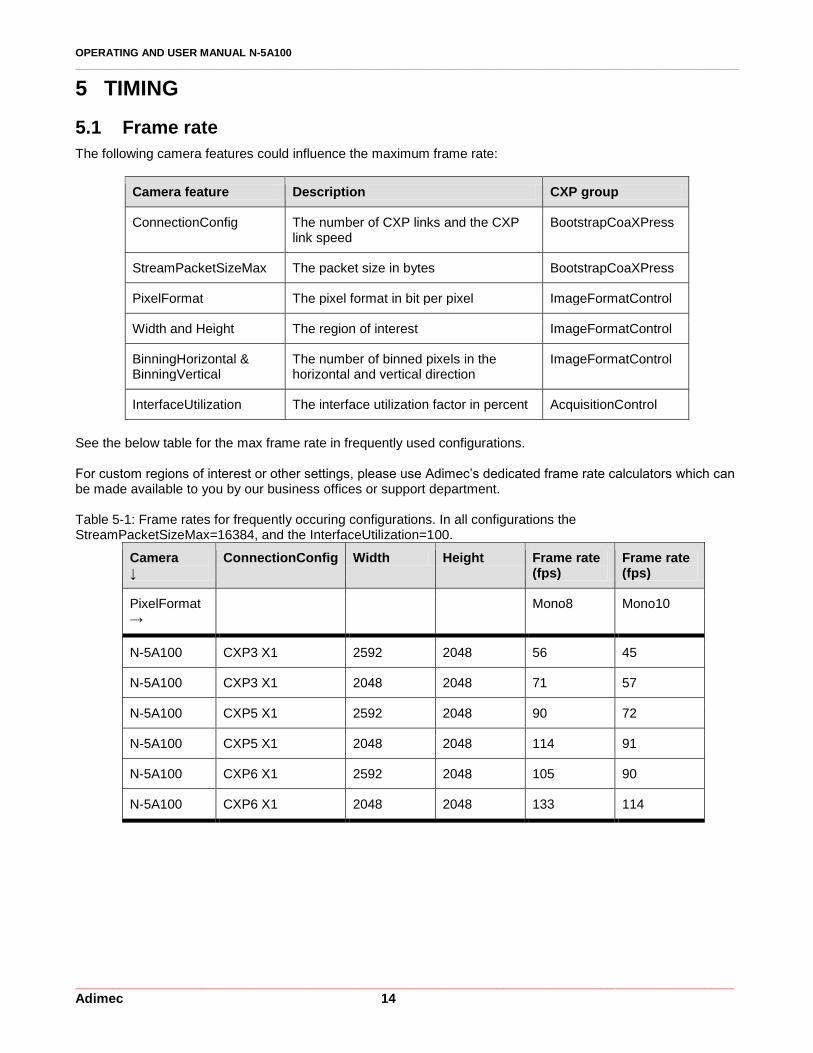
See the below table for the max frame rate in frequently used configurations. For custom regions of interest or other settings, please use Adimec’s dedicated frame rate calculators which can be made available to you by our business offices or support department. Table 5-1: Frame rates for frequently occuring configurations. In all configurations the StreamPacketSizeMax=16384, and the InterfaceUtilization=100.
Camera ↓
ConnectionConfig Width Height Frame rate (fps)
Frame rate (fps)
PixelFormat →
Mono8 Mono10
N-5A100 CXP3 X1 2592 2048 56 45
N-5A100 CXP3 X1 2048 2048 71 57
N-5A100 CXP5 X1 2592 2048 90 72
N-5A100 CXP5 X1 2048 2048 114 91
N-5A100 CXP6 X1 2592 2048 105 90
N-5A100 CXP6 X1 2048 2048 133 114
OPERATING AND USER MANUAL N-5A100 ________________________________________________________________________________________________________________
_________________________________________________________________________________________ Adimec 15
5.2 Operational timing
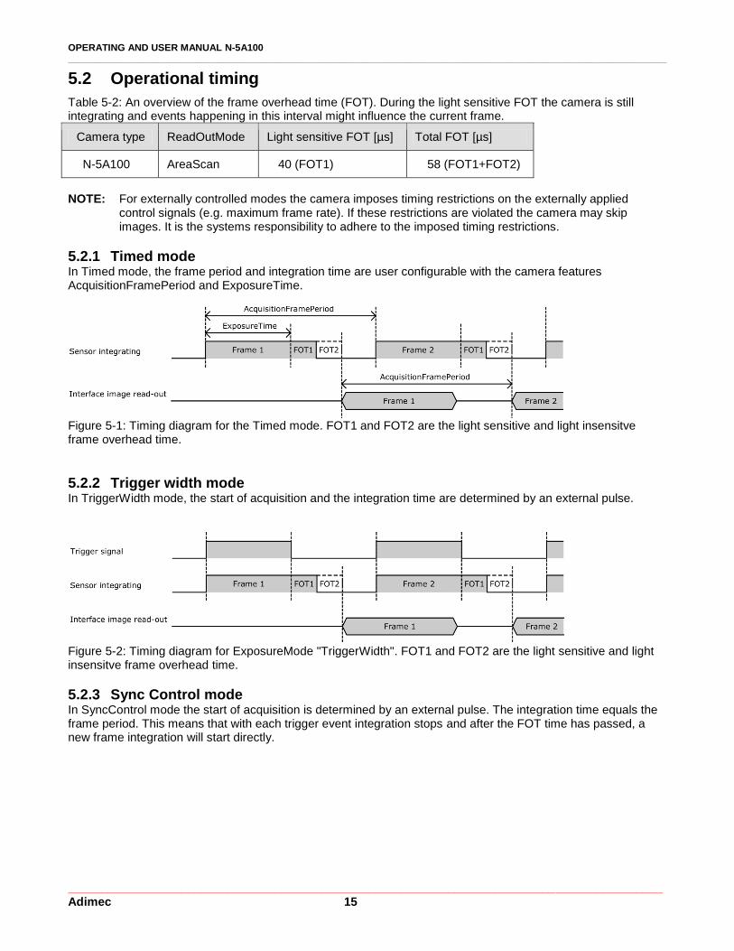
Table 5-2: An overview of the frame overhead time (FOT). During the light sensitive FOT the camera is still integrating and events happening in this interval might influence the current frame.
Camera type ReadOutMode Light sensitive FOT [µs] Total FOT [µs]
N-5A100 AreaScan 40 (FOT1) 58 (FOT1+FOT2)
NOTE: For externally controlled modes the camera imposes timing restrictions on the externally applied
control signals (e.g. maximum frame rate). If these restrictions are violated the camera may skip images. It is the systems responsibility to adhere to the imposed timing restrictions.
5.2.1 Timed mode In Timed mode, the frame period and integration time are user configurable with the camera features AcquisitionFramePeriod and ExposureTime.
Figure 5-1: Timing diagram for the Timed mode. FOT1 and FOT2 are the light sensitive and light insensitve frame overhead time.
5.2.2 Trigger width mode In TriggerWidth mode, the start of acquisition and the integration time are determined by an external pulse.
Figure 5-2: Timing diagram for ExposureMode "TriggerWidth". FOT1 and FOT2 are the light sensitive and light insensitve frame overhead time.
5.2.3 Sync Control mode In SyncControl mode the start of acquisition is determined by an external pulse. The integration time equals the frame period. This means that with each trigger event integration stops and after the FOT time has passed, a new frame integration will start directly.

OPERATING AND USER MANUAL N-5A100 ________________________________________________________________________________________________________________
_________________________________________________________________________________________ Adimec 16
Figure 5-3: Timing diagram for ExposureMode "SyncControlMode". FOT1 and FOT2 are the light sensitive and light insensitive frame overhead time.
5.2.4 Timed trigger control mode In TimedTriggerControl mode, the start of acquisition is determined by an external trigger. The integration time is user configurable with the ExposureTime camera feature.
Figure 5-3: Timing diagram for ExposureMode "TimedTriggerControl". FOT1 and FOT2 are the light sensitive and light insensitive frame overhead time.
5.2.5 Over triggering and frame suppress When external triggers are used to control the camera, it might occur that a new image is ready to be read out while the sensor is still processing the previous image. Such a situation is known as over triggering. A frame that has to wait before being read out due to a previous frame in the processing line will have a longer integration time then requested. Therefore this frame will be suppressed at the camera interface output. Furthermore while a frame is being suppressed, no new triggers will be accepted. This behavior is described in Figure 5-4.
Figure 5-4: Over triggering and frame/trigger suppression. FOT1 and FOT2 are the light sensitive and light insensitive frame overhead time.

OPERATING AND USER MANUAL N-5A100 ________________________________________________________________________________________________________________
_________________________________________________________________________________________ Adimec 17
6 CONTROL OF THE CAMERA
Access to camera functions and data is provided through the CoaXPress (CXP) protocol. The CoaXPress interface is GenICam compliant.
GenICam compliant means that an XML is stored in the camera that is used to translate the camera internal register addresses to the user friendly feature nomenclature as defined by the Standard Features Naming Convention, SFNC. Basically GenICam is designed to bridge the camera specific register addresses with a camera and manufacturer independent user interface. The SFNC feature names should be used to operate the camera.
How to address the SFNC feature names depends on your frame grabber. With CoaXPress frame grabbers a GenICam Application Programming Interface (GenAPI) is provided. This is a software layer that reads the XML from the camera and builds a graphical user interface (GUI) to control the camera. The GUI is often refered to as the GenICam (feature) Browser. Next to the GUI often a scripting language will be available in which you can use the SFNC naming to program the camera and frame grabber according to your desired settings.
To illustrate the workflow of CoaXPress we will describe below what will happen if you set the pixel format to 10 bit in a monochrome camera. When using the GUI:
1. Start the GenICam Browser, The browser will automatically load the XML from the camera and basically builds a user interface.
2. In the GenICam browser search for the feature called PixelFormat. 3. Change this feature to “Mono10”. Often this can be done by selecting “Mono10” from a drop down list.
When using a scripting language
1. Look up the syntax and language used by your frame grabber. 2. By using the frame grabber syntax and language set the feature PixelFormat to Mono10. 3. Execute the script.
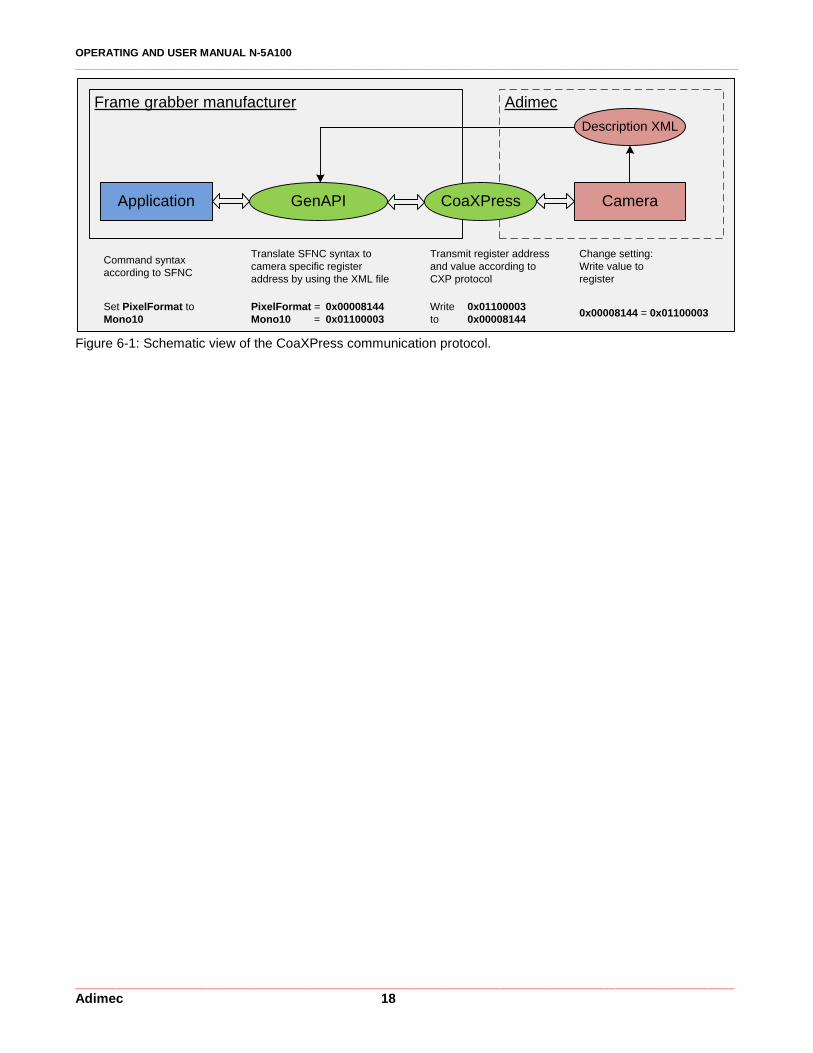
In both cases, for the GUI and for the scripting language, on the background the GenAPI uses the XML to link the feature name PixelFormat to the camera register address 0x00008144. Furthermore it links the feature value name “Mono10” to a value of 0x01100003. Using the CoaXPress interface, the API will then write a value of 0x01100003 to the camera register 0x00008144. Note: The above mentioned register addresses and values are only for illustrational purposes. The exact addresses in your camera might be different.
The above described communication protocol is schematically shown in Figure 6-1.
OPERATING AND USER MANUAL N-5A100 ________________________________________________________________________________________________________________
_________________________________________________________________________________________ Adimec 18
Application CameraGenAPI
Description XML
CoaXPress
Frame grabber manufacturer Adimec
Set PixelFormat to
Mono10
Translate SFNC syntax to
camera specific register
address by using the XML file
Transmit register address
and value according to
CXP protocol
Change setting:
Write value to
register
Command syntax
according to SFNC
PixelFormat = 0x00008144
Mono10 = 0x01100003
Write 0x01100003
to 0x00008144 0x00008144 = 0x01100003
Figure 6-1: Schematic view of the CoaXPress communication protocol.

OPERATING AND USER MANUAL N-5A100 ________________________________________________________________________________________________________________
_________________________________________________________________________________________ Adimec 19
7 CAMERA FEATURES
In section one of this Chapter, the features within the camera are visualized in a functional diagram and a very brief description is given. In the successive sections each feature is explained more extensively by describing and explaining the available features. The sections are sorted along the groups of features as present in the GenICam interface.
7.1 Functional diagram
The diagram in Figure 7-1 shows the main features of the camera. It gives insight in the order in which the features are executed and thus how features might influence each other. A short description of the features is given in Table 7-1.
Image
Sensor
1
Col.
FPNC
Test
Pat.
2
Binning / Vertical
Crop & Mirror
LUT
CXP
IFCXP(0)
1210
8
9
Insert
Crossh
Trigger
Horizontal
mirror
4
DPCGain &
Offset
3 5
Bin
711
Insert
Frame
couter
Horizontal
crop
6
Figure 7-1: Block diagram of the camera describing the variety of available functions.
OPERATING AND USER MANUAL N-5A100 ________________________________________________________________________________________________________________
_________________________________________________________________________________________ Adimec 20
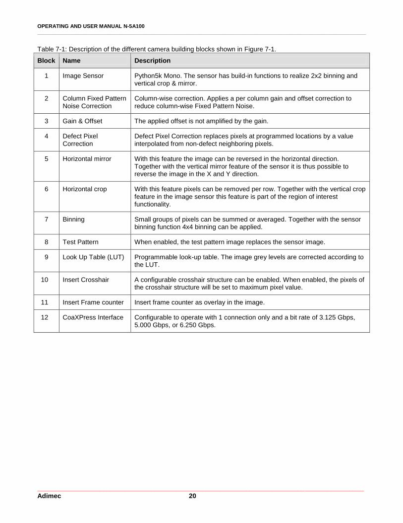
Table 7-1: Description of the different camera building blocks shown in Figure 7-1.
Block Name Description
1 Image Sensor Python5k Mono. The sensor has build-in functions to realize 2x2 binning and vertical crop & mirror.
2 Column Fixed Pattern Noise Correction
Column-wise correction. Applies a per column gain and offset correction to reduce column-wise Fixed Pattern Noise.
3 Gain & Offset The applied offset is not amplified by the gain.
4 Defect Pixel Correction
Defect Pixel Correction replaces pixels at programmed locations by a value interpolated from non-defect neighboring pixels.
5 Horizontal mirror With this feature the image can be reversed in the horizontal direction. Together with the vertical mirror feature of the sensor it is thus possible to reverse the image in the X and Y direction.
6 Horizontal crop With this feature pixels can be removed per row. Together with the vertical crop feature in the image sensor this feature is part of the region of interest functionality.
7 Binning Small groups of pixels can be summed or averaged. Together with the sensor binning function 4x4 binning can be applied.
8 Test Pattern When enabled, the test pattern image replaces the sensor image.
9 Look Up Table (LUT) Programmable look-up table. The image grey levels are corrected according to the LUT.
10 Insert Crosshair A configurable crosshair structure can be enabled. When enabled, the pixels of the crosshair structure will be set to maximum pixel value.
11 Insert Frame counter Insert frame counter as overlay in the image.
12 CoaXPress Interface Configurable to operate with 1 connection only and a bit rate of 3.125 Gbps, 5.000 Gbps, or 6.250 Gbps.
OPERATING AND USER MANUAL N-5A100 ________________________________________________________________________________________________________________
_________________________________________________________________________________________ Adimec 21
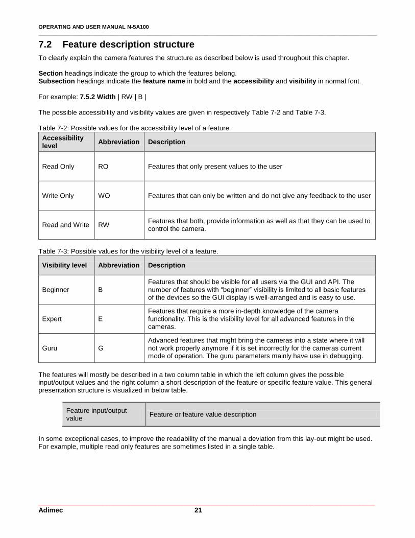
7.2 Feature description structure
To clearly explain the camera features the structure as described below is used throughout this chapter. Section headings indicate the group to which the features belong. Subsection headings indicate the feature name in bold and the accessibility and visibility in normal font. For example: 7.5.2 Width | RW | B | The possible accessibility and visibility values are given in respectively Table 7-2 and Table 7-3. Table 7-2: Possible values for the accessibility level of a feature.
Accessibility level
Abbreviation Description
Read Only RO Features that only present values to the user
Write Only WO Features that can only be written and do not give any feedback to the user
Read and Write RW Features that both, provide information as well as that they can be used to control the camera.
Table 7-3: Possible values for the visibility level of a feature.
Visibility level Abbreviation Description
Beginner B Features that should be visible for all users via the GUI and API. The number of features with “beginner” visibility is limited to all basic features of the devices so the GUI display is well-arranged and is easy to use.
Expert E Features that require a more in-depth knowledge of the camera functionality. This is the visibility level for all advanced features in the cameras.
Guru G Advanced features that might bring the cameras into a state where it will not work properly anymore if it is set incorrectly for the cameras current mode of operation. The guru parameters mainly have use in debugging.
The features will mostly be described in a two column table in which the left column gives the possible input/output values and the right column a short description of the feature or specific feature value. This general presentation structure is visualized in below table.
Feature input/output value
Feature or feature value description
In some exceptional cases, to improve the readability of the manual a deviation from this lay-out might be used. For example, multiple read only features are sometimes listed in a single table.
OPERATING AND USER MANUAL N-5A100 ________________________________________________________________________________________________________________
_________________________________________________________________________________________ Adimec 22
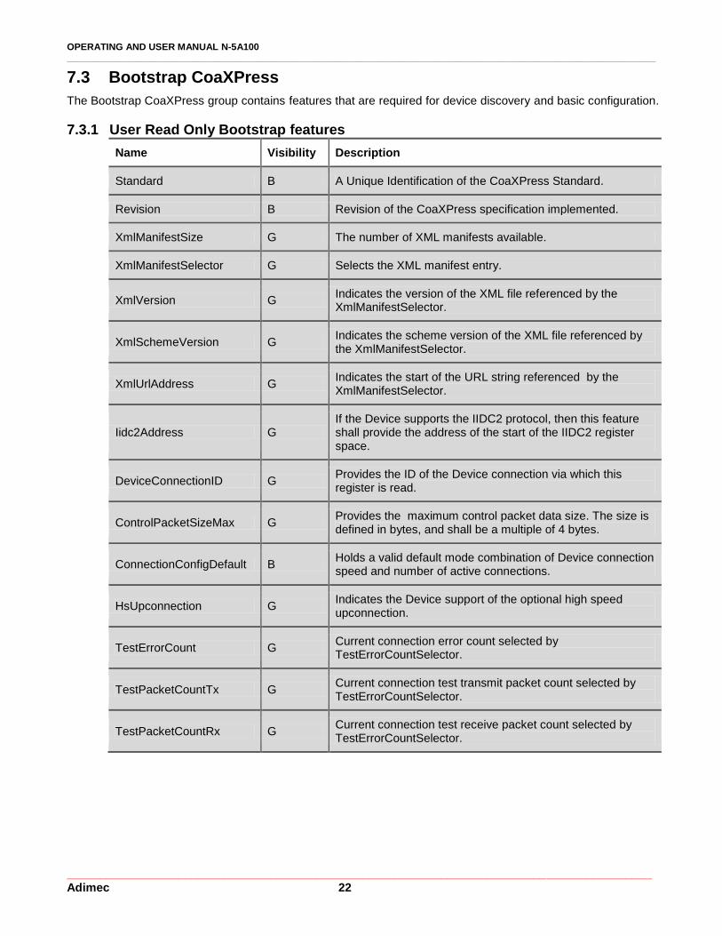
7.3 Bootstrap CoaXPress
The Bootstrap CoaXPress group contains features that are required for device discovery and basic configuration.
7.3.1 User Read Only Bootstrap features
Name Visibility Description
Standard B A Unique Identification of the CoaXPress Standard.
Revision B Revision of the CoaXPress specification implemented.
XmlManifestSize G The number of XML manifests available.
XmlManifestSelector G Selects the XML manifest entry.
XmlVersion G Indicates the version of the XML file referenced by the XmlManifestSelector.
XmlSchemeVersion G Indicates the scheme version of the XML file referenced by the XmlManifestSelector.
XmlUrlAddress G Indicates the start of the URL string referenced by the XmlManifestSelector.
Iidc2Address G If the Device supports the IIDC2 protocol, then this feature shall provide the address of the start of the IIDC2 register space.
DeviceConnectionID G Provides the ID of the Device connection via which this register is read.
ControlPacketSizeMax G Provides the maximum control packet data size. The size is defined in bytes, and shall be a multiple of 4 bytes.
ConnectionConfigDefault B Holds a valid default mode combination of Device connection speed and number of active connections.
HsUpconnection G Indicates the Device support of the optional high speed upconnection.
TestErrorCount G Current connection error count selected by TestErrorCountSelector.
TestPacketCountTx G Current connection test transmit packet count selected by TestErrorCountSelector.
TestPacketCountRx G Current connection test receive packet count selected by TestErrorCountSelector.

OPERATING AND USER MANUAL N-5A100 ________________________________________________________________________________________________________________
_________________________________________________________________________________________ Adimec 23
Name Visibility Description
WidthAddress G
This feature provides the address in the manufacturer-specific register space of the feature with the corresponding name.
HeightAddress G
AcquisitionModeAddress G
AcquisitionStartAddress G
AcquisitionStopAddress G
PixelFormatAddress G
DeviceTapGeometryAddress G
Image1StreamIDAddress G
7.3.2 Beginner writable Bootstrap features
7.3.2.1 ConnectionConfig | RW | B | With ConnectionConfig the connection speed and number of active connections is configured. NOTE: Acquisition must be stopped before changing the ConnectionConfig feature.
CXP3_X1 1 connection at 3.125 Gb/s
CXP5_X1 1 connection at 5.000 Gb/s
CXP6_X1 1 connection at 6.250 Gb/s
7.3.3 Guru writable Bootstrap features Features with a “Guru” visibility level control advanced camera settings. If these features are used incorrectly the camera might not work properly anymore. Most of the time guru parameters mainly have use in debugging.
Name Access Description
ConnectionReset RW Write “1” to reset all connections of the Device.
MasterHostConnectionID RW Holds the Host Connection ID of the Host connection connected to the Device Master connection.
StreamPacketSizeMax RW
Provide the maximum stream packet data size the Host can accept. The size is defined in bytes, and shall be a multiple of 4 bytes. The default value is always “0”. This value is set by the Host and not the Device.
TestMode RW Enables test packet transmission from Device to Host.
TestErrorCountSelector RW Selects the TestErrorCount register. Selection shall be a valid Device Connection ID.
ElectricalCompliancyTest RW Supports the formal electrical compliancy testing of the Device.
OPERATING AND USER MANUAL N-5A100 ________________________________________________________________________________________________________________
_________________________________________________________________________________________ Adimec 24
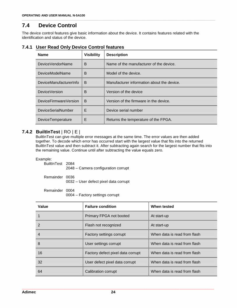
7.4 Device Control
The device control features give basic information about the device. It contains features related with the identification and status of the device.
7.4.1 User Read Only Device Control features
Name Visibility Description
DeviceVendorName B Name of the manufacturer of the device.
DeviceModelName B Model of the device.
DeviceManufacturerInfo B Manufacturer information about the device.
DeviceVersion B Version of the device
DeviceFirmwareVersion B Version of the firmware in the device.
DeviceSerialNumber E Device serial number
DeviceTemperature E Returns the temperature of the FPGA.
7.4.2 BuiltInTest | RO | E | BuiltInTest can give multiple error messages at the same time. The error values are then added together. To decode which error has occurred start with the largest value that fits into the returned BuiltInTest value and then subtract it. After subtracting again search for the largest number that fits into the remaining value. Continue until after subtracting the value equals zero.
Example:
BuiltInTest 2084 2048 – Camera configuration corrupt
Remainder 0036
0032 – User defect pixel data corrupt
Remainder 0004 0004 – Factory settings corrupt
Value Failure condition When tested
1 Primary FPGA not booted At start-up
2 Flash not recognized At start-up
4 Factory settings corrupt When data is read from flash
8 User settings corrupt When data is read from flash
16 Factory defect pixel data corrupt When data is read from flash
32 User defect pixel data corrupt When data is read from flash
64 Calibration corrupt When data is read from flash
OPERATING AND USER MANUAL N-5A100 ________________________________________________________________________________________________________________
_________________________________________________________________________________________ Adimec 25
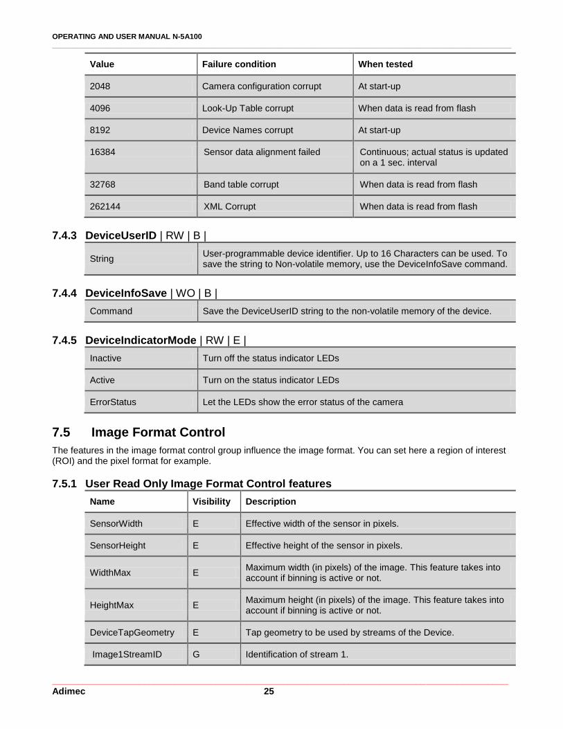
Value Failure condition When tested
2048 Camera configuration corrupt At start-up
4096 Look-Up Table corrupt When data is read from flash
8192 Device Names corrupt At start-up
16384 Sensor data alignment failed Continuous; actual status is updated on a 1 sec. interval
32768 Band table corrupt When data is read from flash
262144 XML Corrupt When data is read from flash
7.4.3 DeviceUserID | RW | B |
String User-programmable device identifier. Up to 16 Characters can be used. To save the string to Non-volatile memory, use the DeviceInfoSave command.
7.4.4 DeviceInfoSave | WO | B |
Command Save the DeviceUserID string to the non-volatile memory of the device.
7.4.5 DeviceIndicatorMode | RW | E |
Inactive Turn off the status indicator LEDs
Active Turn on the status indicator LEDs
ErrorStatus Let the LEDs show the error status of the camera
7.5 Image Format Control
The features in the image format control group influence the image format. You can set here a region of interest (ROI) and the pixel format for example.
7.5.1 User Read Only Image Format Control features
Name Visibility Description
SensorWidth E Effective width of the sensor in pixels.
SensorHeight E Effective height of the sensor in pixels.
WidthMax E Maximum width (in pixels) of the image. This feature takes into account if binning is active or not.
HeightMax E Maximum height (in pixels) of the image. This feature takes into account if binning is active or not.
DeviceTapGeometry E Tap geometry to be used by streams of the Device.
Image1StreamID G Identification of stream 1.
OPERATING AND USER MANUAL N-5A100 ________________________________________________________________________________________________________________
_________________________________________________________________________________________ Adimec 26
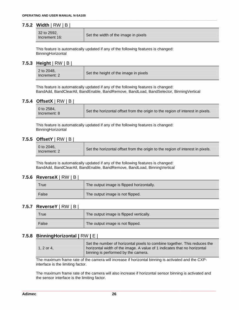
7.5.2 Width | RW | B |
32 to 2592, Increment 16:
Set the width of the image in pixels
This feature is automatically updated if any of the following features is changed: BinningHorizontal
7.5.3 Height | RW | B |
2 to 2048, Increment: 2
Set the height of the image in pixels
This feature is automatically updated if any of the following features is changed: BandAdd, BandClearAll, BandEnable, BandRemove, BandLoad, BandSelector, BinningVertical
7.5.4 OffsetX | RW | B |
0 to 2584, Increment: 8
Set the horizontal offset from the origin to the region of interest in pixels.
This feature is automatically updated if any of the following features is changed: BinningHorizontal
7.5.5 OffsetY | RW | B |
0 to 2046, Increment: 2
Set the horizontal offset from the origin to the region of interest in pixels.
This feature is automatically updated if any of the following features is changed: BandAdd, BandClearAll, BandEnable, BandRemove, BandLoad, BinningVertical
7.5.6 ReverseX | RW | B |
True The output image is flipped horizontally.
False The output image is not flipped.
7.5.7 ReverseY | RW | B |
True The output image is flipped vertically.
False The output image is not flipped.
7.5.8 BinningHorizontal | RW | E |
1, 2 or 4, Set the number of horizontal pixels to combine together. This reduces the horizontal width of the image. A value of 1 indicates that no horizontal binning is performed by the camera.
The maximum frame rate of the camera will increase if horizontal binning is activated and the CXP-interface is the limiting factor.
The maximum frame rate of the camera will also increase if horizontal sensor binning is activated and the sensor interface is the limiting factor.

OPERATING AND USER MANUAL N-5A100 ________________________________________________________________________________________________________________
_________________________________________________________________________________________ Adimec 27
NOTE: For 2x binning, the binning is performed on the sensor. For 4x binning , the binning is a combination of 2x on sensor and 2x digital binning.
7.5.9 BinningVertical | RW | E |
1, 2 or 4, Set the number of vertical pixels to combine together. This reduces the vertical height of the image. A value of 1 indicates that no vertical binning is performed by the camera.
NOTE: For 2x binning, the binning is performed on the sensor. For 4x binning , the binning is a combination of 2x on sensor and 2x digital binning.
NOTE: When vertical sensor binning is enabled, the integration time and readout time should not overlap. The
sensor integration cannot start before the frame readout is completed. If the integration time starts within the frame readout, the sensor will stop working until the camera is rebooted.
7.5.10 BinningMode | RW | E |
Sum Set the binned pixel signal level to the sum of the signal levels of the individual pixels of which it is composed.
Average Set the binned pixel signal level to the average of the signal levels of the individual pixels of which it is composed.
By using binning you can reduce the noise due to averaging. It is also possible to increase the frame rate. Table 7-4: Frame rates for frequently occuring configurations. In all configurations the ConnectionConfig=CXP6_X1, PixelFormat=Mono8, StreamPacketSizeMax=16384, and the InterfaceUtilization=100. Width and height refer to the width and height without binning.
Camera ↓
Width Height Frame rate (fps)
Frame rate (fps)
Frame rate (fps)
Binning →
1x1 2x2 4x4
N-5A100 2592 2048 105 211 211
N-5A100 2048 2048 133 235 235
7.5.11 PixelFormat | RW | B |
Mono8 Set the pixel format for acquisition to 8 bit mono.
Mono10 Set the pixel format for acquisition to 10 bit mono.
NOTE: PixelFormat can only be changed if there is no acquisition active.
OPERATING AND USER MANUAL N-5A100 ________________________________________________________________________________________________________________
_________________________________________________________________________________________ Adimec 28
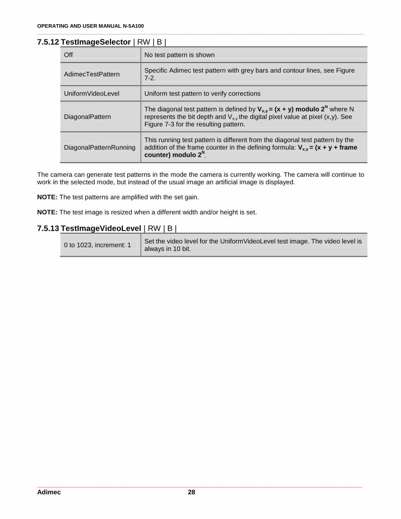
7.5.12 TestImageSelector | RW | B |
Off No test pattern is shown
AdimecTestPattern Specific Adimec test pattern with grey bars and contour lines, see Figure 7-2.
UniformVideoLevel Uniform test pattern to verify corrections
DiagonalPattern The diagonal test pattern is defined by Vx,y = (x + y) modulo 2
N where N
represents the bit depth and Vx,y the digital pixel value at pixel (x,y). See Figure 7-3 for the resulting pattern.
DiagonalPatternRunning This running test pattern is different from the diagonal test pattern by the addition of the frame counter in the defining formula: Vx,y = (x + y + frame counter) modulo 2
N.
The camera can generate test patterns in the mode the camera is currently working. The camera will continue to work in the selected mode, but instead of the usual image an artificial image is displayed. NOTE: The test patterns are amplified with the set gain. NOTE: The test image is resized when a different width and/or height is set.
7.5.13 TestImageVideoLevel | RW | B |
0 to 1023, increment: 1 Set the video level for the UniformVideoLevel test image. The video level is always in 10 bit.
OPERATING AND USER MANUAL N-5A100 ________________________________________________________________________________________________________________
_________________________________________________________________________________________ Adimec 29
63
12
7
19
1
25
5
31
9
38
3
44
7
51
1
57
5
63
9
70
3
76
7
83
1
89
5
95
9
10
23
Gray scale
0 63
448 511
512 575
960 1023
166
166
256
43
43
Vertical
center
Horizontal
center
Top gray bars
Bottom gray bars
1023
511
0
512
10
23
95
9
89
5
83
1
76
7
70
3
63
9
57
5
51
1
44
7
38
3
31
9
25
5
19
1
12
7
63
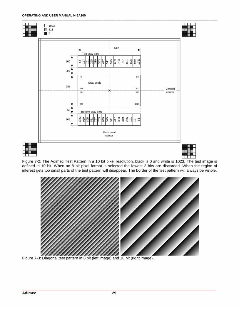
Figure 7-2: The Adimec Test Pattern in a 10 bit pixel resolution, black is 0 and white is 1023. The test image is defined in 10 bit. When an 8 bit pixel format is selected the lowest 2 bits are discarded. When the region of interest gets too small parts of the test pattern will disappear. The border of the test pattern will always be visible.
Figure 7-3: Diagonal test pattern in 8 bit (left image) and 10 bit (right image).
OPERATING AND USER MANUAL N-5A100 ________________________________________________________________________________________________________________
_________________________________________________________________________________________ Adimec 30
7.5.14 FrameCounter | RO | B |
Integer Provides the current frame count
This feature is automatically updated if any of the following features is changed: FrameCounterReset
7.5.15 FrameCounterReset | WO | B |
Command Reset the frame counter
7.5.16 FrameCounterOverlay | RW | E |
True Add a frame counter overlay to the image sent by the device. The frame counter is displayed in the first 4 bytes of the image, mapped in the 8 most significant bits.
False No frame counter will be added to the images.
7.5.17 CrosshairOverlay | RW | E |
True Add a crosshair overlay to the image sent by the device. The crosshair is applied to the center of the image and is 2 pixels wide. The gray level of the crosshair pattern equals the maximum output level.
False No crosshair will be added to the camera image.
7.6 Acquisition Control
In this group you find all features related to basic camera operation.
7.6.1 AcquisitionMode | RW | B |
Continuous Set the acquisition mode of the device.
NOTE: AcquisitionMode is related to how data is transferred over the interface. ExposureMode is related to the sensor operation.
7.6.2 AcquisitionStart | RW | B |
Command Start the Acquisition of the device.
7.6.3 AcquisitionStop | RW | B |
Command Stop the Acquisition of the device at the end of the current frame.
7.6.4 AcquisitionFrameRate | RW | B |
Min 10 Hz Increment: undefined
Control the acquisition rate (in Hertz) at which the frames are captured. The maximum depends on the camera configuration. The frame rate is rounded such that AcquisitionFramePeriod is a multiple of 1 µs.
This feature is automatically updated if any of the following features is changed: AcquisitionFrameRate, AcquisitionFramePeriod, AcquisitionMaxFrameRate, BinningHorizontal, ConnectionConfig, InterfaceUtilization, PixelFormat, ReadOutMode, StreamPacketSizeMax, Width, Height
OPERATING AND USER MANUAL N-5A100 ________________________________________________________________________________________________________________
_________________________________________________________________________________________ Adimec 31
7.6.5 AcquisitionFramePeriod | RW | B |
Max 100000 µs Increment: 1 µs
Control the acquisition rate (in 1 µs steps) at which the frames are captured. The minimum depends on the camera configuration.
This feature is automatically updated if any of the following features is changed: AcquisitionFrameRate, AcquisitionFramePeriod, AcquisitionMaxFrameRate, BinningHorizontal, ConnectionConfig, InterfaceUtilization, PixelFormat, ReadOutMode, StreamPacketSizeMax, Width, Height
7.6.6 AcquisitionFramePeriodRaw | RW | B |
Max 100000 µs Increment: 1 µs
Control the acquisition rate (in 1 µs steps) at which the frames are captured. The minimum depends on the camera configuration.
This feature is automatically updated if any of the following features is changed: AcquisitionFrameRate, AcquisitionFramePeriod, AcquisitionMaxFrameRate, BinningHorizontal, ConnectionConfig, InterfaceUtilization, PixelFormat, ReadOutMode, StreamPacketSizeMax, Width, Height
7.6.7 AcquisitionMaxFrameRate | WO | B |
Command Set the camera to the maximum frame rate as is possible with the current settings.
7.6.8 TriggerSource | RW | B |
Trigger Use trigger over CXP.
Not applicable in ExposureMode Timed.
7.6.9 TriggerActivation | RW | B |
FallingEdge Use the falling edge as the trigger activation event.
RisingEdge Use the rising edge as the trigger activation event.
Not applicable in ExposureMode Timed.
7.6.10 TriggerDelayTime | RW | B |
1 to 65535 µs Set the trigger delay time
Not applicable in ExposureMode Timed. This feature is automatically updated if any of the following features is changed: TriggerDelayTimeRaw
7.6.11 TriggerDelayTimeRaw | RW | B |
1 to 65535 µs Set the trigger delay time in 1 µs steps.
Not applicable in ExposureMode Timed. This feature is automatically updated if any of the following features is changed: TriggerDelayTime
OPERATING AND USER MANUAL N-5A100 ________________________________________________________________________________________________________________
_________________________________________________________________________________________ Adimec 32
7.6.12 ExposureMode | RW | B |
Timed Free run mode. The camera is master: frame period and integration time are both fixed and controllable via the AcquisitionFramePeriod feature and ExposureTime feature respectively.
TriggerWidth Camera is slave; In this mode an external trigger starts integration. The integration time is determined by the duration of the trigger pulse.
SyncControlMode Camera is slave: Start and stop of integration time are determined by the start of the trigger. The frame period equals the integration time.
TimedTriggerControl
Camera is slave: Start of integration time is determined by the start of the trigger, the integration time is fixed and can be controlled via the ExposureTime feature. When TimedTriggerControl mode is used the ExposureTime is clipped against the configured AcquisitionFramePeriod used for the Timed mode. The user is responsible to change AcquisitionFramePeriod such that the desired ExposureTime can be configured.
Acquisition must be stopped when changing the ExposureMode. For more details about the timing of the various modes, see section 5.2.
7.6.13 ExposureTime | RW | B |
Min: 1µs Max: AquisitionFramePeriod Increment: 1 µs
Set the exposure time (in 1µs steps). The exposure time is not corrected for the light sensitive FOT of the sensor. To obtain the actual integration time the light sensitive FOT has to be added to the exposure time set with this feature. See section 5.2 for the FOT times.
This feature is automatically updated if any of the following features is changed: ExposureTimeRaw
7.6.14 ExposureTimeRaw | RW | B |
Min: 1µs Max: AquisitionFramePeriod Increment: 1 µs
Set the exposure time (in 1µs steps). The exposure time is not corrected for the light sensitive FOT of the sensor. To obtain the actual integration time the light sensitive FOT has to be added to the exposure time set with this feature. See section 5.2 for the FOT times.
This feature is automatically updated if any of the following features is changed: ExposureTime, AcquisitionFramePeriodRaw
7.6.15 InterfaceUtilization | RW | B |
50% to 100%, increment 1%
Decrease the data rate of the interface in order to prevent the frame grabber from being overrun. Example: a utilization factor of 50 halves the available interface bandwidth.
7.7 Analog Control
Analog control functions like gain can be found in this group.

OPERATING AND USER MANUAL N-5A100 ________________________________________________________________________________________________________________
_________________________________________________________________________________________ Adimec 33
7.7.1 GainSelector | RW | B |
All Gain features will influence all pixels
NOTE: Only digital gain is available.
NOTE: Gain is applied before BlackLevel.
7.7.2 Gain | RW | B |
GainSelector value Gain range (increment 0.001)
All 1 to 32
This feature is automatically updated if any of the following features is changed: GainRaw, GainSelector
7.7.3 GainRaw | RW | B |
GainSelector value Gain range (increment 1)
All 1000 to 32000
This feature is automatically updated if any of the following features is changed: Gain, GainSelector
7.7.4 BlackLevel | RW | B |
0 to 511 Increment 1
Control the analog black level as an absolute physical value.
This feature is automatically updated if any of the following features is changed: BlackLevelRaw For the 8-bit pixel formats, the configured value is presented at the video output as BlackLevel/4. For example a BlackLevel setting of 20 wil give a black level of 5 when the bit depth is set to 8.
NOTE: BlackLevel is applied after gain.
7.7.5 BlackLevelRaw | RW | B |
0 to 511 Increment: 1
Control the analog black level as an absolute physical value.
This feature is automatically updated if any of the following features is changed: BlackLevel For the 8-bit pixel formats, the configured value is presented at the video output as BlackLevelRaw/4.
NOTE: BlackLevelRaw is applied after gain.
7.8 Factory
The factory settings are not user accessible, this mode is only required to adjust factory settings.

OPERATING AND USER MANUAL N-5A100 ________________________________________________________________________________________________________________
_________________________________________________________________________________________ Adimec 34
7.9 LUT Control
This group describes the Look Up Table features.
7.9.1 LUTEnable | RW | E |
True Activate the Look Up Table (LUT). The LUT transforms the video signal from the image processing to the output.
False Deactivate the Look Up Table.
7.9.2 LUTStart | WO | E |
Command Start the creation of a LUT. The exact amount of 1024 entries should be written using the LUTValue feature to successfully create a LUT.
7.9.3 LUTValue | RW | E |
0 to 1023, Increment 1
After executing LUTStart, use this feature to consecutively write each index of the LUT. This feature also returns the value that is written at the LUT index selected with the LUTIndex feature.
This feature is automatically updated if any of the following features is changed: LUTIndex
7.9.4 LUTEnd| WO | E |
Command Finish the creation of a LUT. Make sure you wrote a value to all 1024 LUT entries.
7.9.5 LUTIndex | RW | E |
0 to 1023, Increment 1
Select the LUT index for which you want to know the assigned value. The assigned value will be displayed in the LUTValue feature.
7.9.6 LUTStatus | RO | E |
LUT_Idle LUT programming sequence in idle situation
LUT_Started LUT programming sequence started
LUT_Restarted LUT programming sequence restarted
LUT_TooMuchEntries Too much LUT entries (LUTValue) written before LUTEnd command is written
LUT_NotEnoughEntries Not enough LUT entries (LUTValue) written before LUTEnd command is written
LUT_Stored LUT programming sequence finished and stored in memory
LUT_NotStarted LUT programming sequence has not been started yet
This feature is automatically updated if any of the following features is changed: LUTStart, LUTEnd
OPERATING AND USER MANUAL N-5A100 ________________________________________________________________________________________________________________
_________________________________________________________________________________________ Adimec 35
7.10 Transport Layer Control
7.10.1 PayloadSize | RO | E |
Integer Provides the number of bytes transferred for each image or chunk on the stream channel.
This feature is automatically updated if any of the following features is changed: Width, Height, PixelFormat
7.11 Defect Pixel
Up to 1000 defect pixels can be stored in the camera. From factory the defect pixel list contains the major defects that are identified during the manufacturing process. The factory list is limited to 700 pixels. The user can always add at least 300 custom defect pixels.
7.11.1 DefectPixelCorrectionEnable | RW | G |
True Enable the defect pixel correction, the pixels as listed in the volatile memory will be corrected.
False Disable the defect pixel correction
7.11.2 DefectPixelTestMode | RW | E |
Off Turn off the defect pixel test mode
MarkDefectsWhiteOnVideo Mark defects white on video, for use in a dark environment
MarkDefectsBlackOnVideo Mark defects black on video, for use in a light environment
ShowDefectsAsWhiteOnBlackBackground Generate a non-video test pattern that indicates the defect pixels.
7.11.3 DefectPixelTotal | RO | E |
Integer Returns the total amount of pixels that will be corrected.
This feature is automatically updated if any of the following features is changed: DefectPixelAdd, DefectPixelClearAll, DefectPixelRemove, DefectPixelRestore, DefectPixelRestoreFactory
7.11.4 DefectPixelSelect | RW | E |
0 to 1000, increment 1
Select the defect pixel index from which you want to know the coordinates. The coordinates are displayed in the DefectPixelReadX and DefectPixelReadY feature.
This feature is automatically updated if any of the following features is changed: DefectPixelAdd, DefectPixelClearAll, DefectPixelRemove, DefectPixelRestoreFactory
OPERATING AND USER MANUAL N-5A100 ________________________________________________________________________________________________________________
_________________________________________________________________________________________ Adimec 36
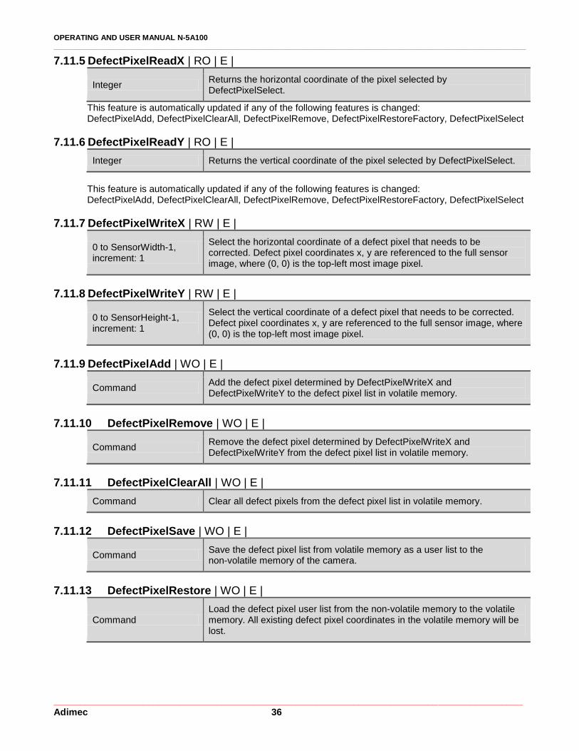
7.11.5 DefectPixelReadX | RO | E |
Integer Returns the horizontal coordinate of the pixel selected by DefectPixelSelect.
This feature is automatically updated if any of the following features is changed: DefectPixelAdd, DefectPixelClearAll, DefectPixelRemove, DefectPixelRestoreFactory, DefectPixelSelect
7.11.6 DefectPixelReadY | RO | E |
Integer Returns the vertical coordinate of the pixel selected by DefectPixelSelect.
This feature is automatically updated if any of the following features is changed: DefectPixelAdd, DefectPixelClearAll, DefectPixelRemove, DefectPixelRestoreFactory, DefectPixelSelect
7.11.7 DefectPixelWriteX | RW | E |
0 to SensorWidth-1, increment: 1
Select the horizontal coordinate of a defect pixel that needs to be corrected. Defect pixel coordinates x, y are referenced to the full sensor image, where (0, 0) is the top-left most image pixel.
7.11.8 DefectPixelWriteY | RW | E |
0 to SensorHeight-1, increment: 1
Select the vertical coordinate of a defect pixel that needs to be corrected. Defect pixel coordinates x, y are referenced to the full sensor image, where (0, 0) is the top-left most image pixel.
7.11.9 DefectPixelAdd | WO | E |
Command Add the defect pixel determined by DefectPixelWriteX and DefectPixelWriteY to the defect pixel list in volatile memory.
7.11.10 DefectPixelRemove | WO | E |
Command Remove the defect pixel determined by DefectPixelWriteX and DefectPixelWriteY from the defect pixel list in volatile memory.
7.11.11 DefectPixelClearAll | WO | E |
Command Clear all defect pixels from the defect pixel list in volatile memory.
7.11.12 DefectPixelSave | WO | E |
Command Save the defect pixel list from volatile memory as a user list to the non-volatile memory of the camera.
7.11.13 DefectPixelRestore | WO | E |
Command Load the defect pixel user list from the non-volatile memory to the volatile memory. All existing defect pixel coordinates in the volatile memory will be lost.

OPERATING AND USER MANUAL N-5A100 ________________________________________________________________________________________________________________
_________________________________________________________________________________________ Adimec 37
7.11.14 DefectPixelRestoreFactory | WO | E |
Command Load the factory default defect pixel list from the non-volatile memory to the volatile memory. All existing defect pixel coordinates in the volatile memory will be lost.
7.11.15 DefectPixelSaveAsFactoryDefault | WO | G |
Command Not accessible by the user
The correction method that is applied depends on the local defect distribution. A defect pixel correction is available that replaces a defect pixel by a horizontally interpolated value, a vertically interpolated value, or a horizontal nearest neighbor value. The available correction methods are illustrated in Figure 7-4. The user does not have control about which method is being applied. The defect correction is currently not band-aware; defects at the vertical border of a band may be corrected with pixel information of the adjacent band, if vertical correction is chosen.
Figure 7-4: An overview of the defect pixel correction methods. In the mask box, 1 indicates a defect pixel, 0 a working pixel and the pixels with an x are not involved in the correction. After correction, the center defect pixel in the mask will be given the value that is obtained by adding the surrounding pixels with the weighting factors as indicated in the correction box.
7.12 Dark Field
This group contains all features related to column based dark field correction, i.e. a compensation for Dark Signal Non-Uniformities (DSNU) in between columns.
7.12.1 DF_ColumnOffsetCorrection | RW | E |
True Enable the dark field column offset correction.
False Disable the dark field column offset correction
OPERATING AND USER MANUAL N-5A100 ________________________________________________________________________________________________________________
_________________________________________________________________________________________ Adimec 38
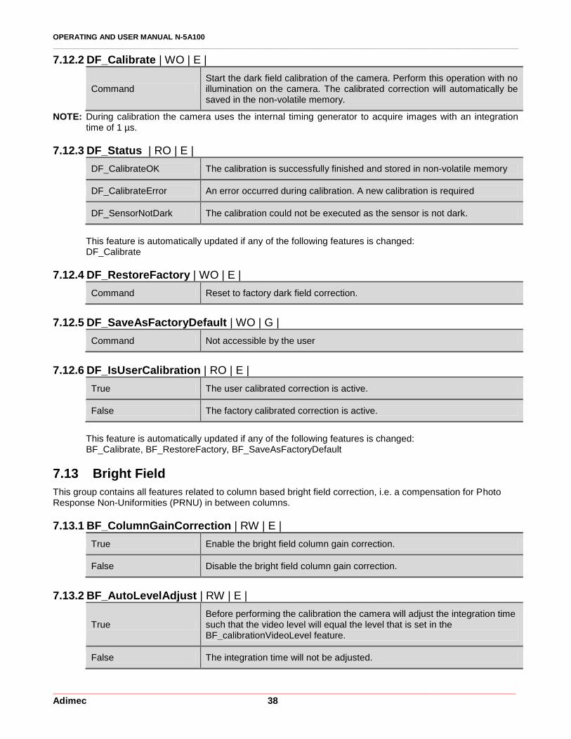
7.12.2 DF_Calibrate | WO | E |
Command Start the dark field calibration of the camera. Perform this operation with no illumination on the camera. The calibrated correction will automatically be saved in the non-volatile memory.
NOTE: During calibration the camera uses the internal timing generator to acquire images with an integration time of 1 µs.
7.12.3 DF_Status | RO | E |
DF_CalibrateOK The calibration is successfully finished and stored in non-volatile memory
DF_CalibrateError An error occurred during calibration. A new calibration is required
DF_SensorNotDark The calibration could not be executed as the sensor is not dark.
This feature is automatically updated if any of the following features is changed: DF_Calibrate
7.12.4 DF_RestoreFactory | WO | E |
Command Reset to factory dark field correction.
7.12.5 DF_SaveAsFactoryDefault | WO | G |
Command Not accessible by the user
7.12.6 DF_IsUserCalibration | RO | E |
True The user calibrated correction is active.
False The factory calibrated correction is active.
This feature is automatically updated if any of the following features is changed: BF_Calibrate, BF_RestoreFactory, BF_SaveAsFactoryDefault
7.13 Bright Field
This group contains all features related to column based bright field correction, i.e. a compensation for Photo Response Non-Uniformities (PRNU) in between columns.
7.13.1 BF_ColumnGainCorrection | RW | E |
True Enable the bright field column gain correction.
False Disable the bright field column gain correction.
7.13.2 BF_AutoLevelAdjust | RW | E |
True Before performing the calibration the camera will adjust the integration time such that the video level will equal the level that is set in the BF_calibrationVideoLevel feature.
False The integration time will not be adjusted.
OPERATING AND USER MANUAL N-5A100 ________________________________________________________________________________________________________________
_________________________________________________________________________________________ Adimec 39
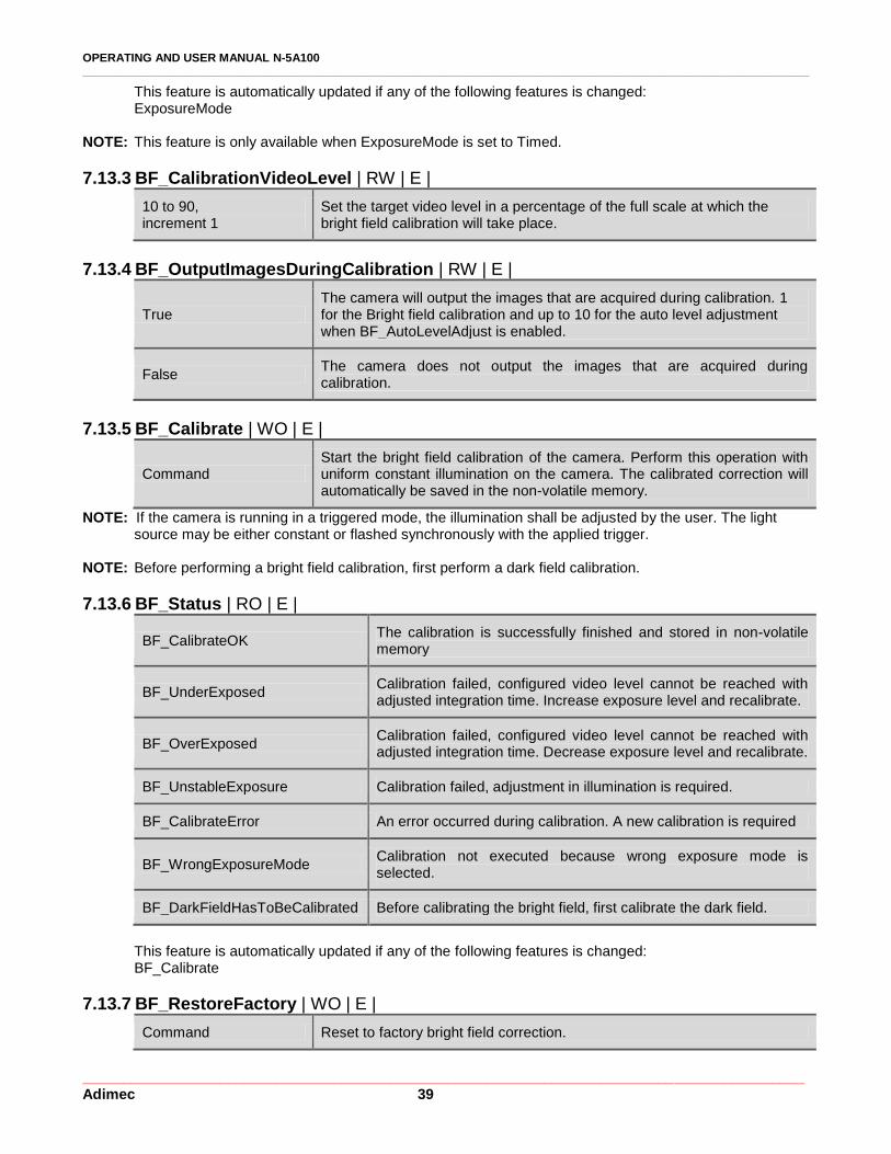
This feature is automatically updated if any of the following features is changed: ExposureMode
NOTE: This feature is only available when ExposureMode is set to Timed.
7.13.3 BF_CalibrationVideoLevel | RW | E |
10 to 90, increment 1
Set the target video level in a percentage of the full scale at which the bright field calibration will take place.
7.13.4 BF_OutputImagesDuringCalibration | RW | E |
True The camera will output the images that are acquired during calibration. 1 for the Bright field calibration and up to 10 for the auto level adjustment when BF_AutoLevelAdjust is enabled.
False The camera does not output the images that are acquired during calibration.
7.13.5 BF_Calibrate | WO | E |
Command Start the bright field calibration of the camera. Perform this operation with uniform constant illumination on the camera. The calibrated correction will automatically be saved in the non-volatile memory.
NOTE: If the camera is running in a triggered mode, the illumination shall be adjusted by the user. The light source may be either constant or flashed synchronously with the applied trigger.
NOTE: Before performing a bright field calibration, first perform a dark field calibration.
7.13.6 BF_Status | RO | E |
BF_CalibrateOK The calibration is successfully finished and stored in non-volatile memory
BF_UnderExposed Calibration failed, configured video level cannot be reached with adjusted integration time. Increase exposure level and recalibrate.
BF_OverExposed Calibration failed, configured video level cannot be reached with adjusted integration time. Decrease exposure level and recalibrate.
BF_UnstableExposure Calibration failed, adjustment in illumination is required.
BF_CalibrateError An error occurred during calibration. A new calibration is required
BF_WrongExposureMode Calibration not executed because wrong exposure mode is selected.
BF_DarkFieldHasToBeCalibrated Before calibrating the bright field, first calibrate the dark field.
This feature is automatically updated if any of the following features is changed: BF_Calibrate
7.13.7 BF_RestoreFactory | WO | E |
Command Reset to factory bright field correction.
OPERATING AND USER MANUAL N-5A100 ________________________________________________________________________________________________________________
_________________________________________________________________________________________ Adimec 40
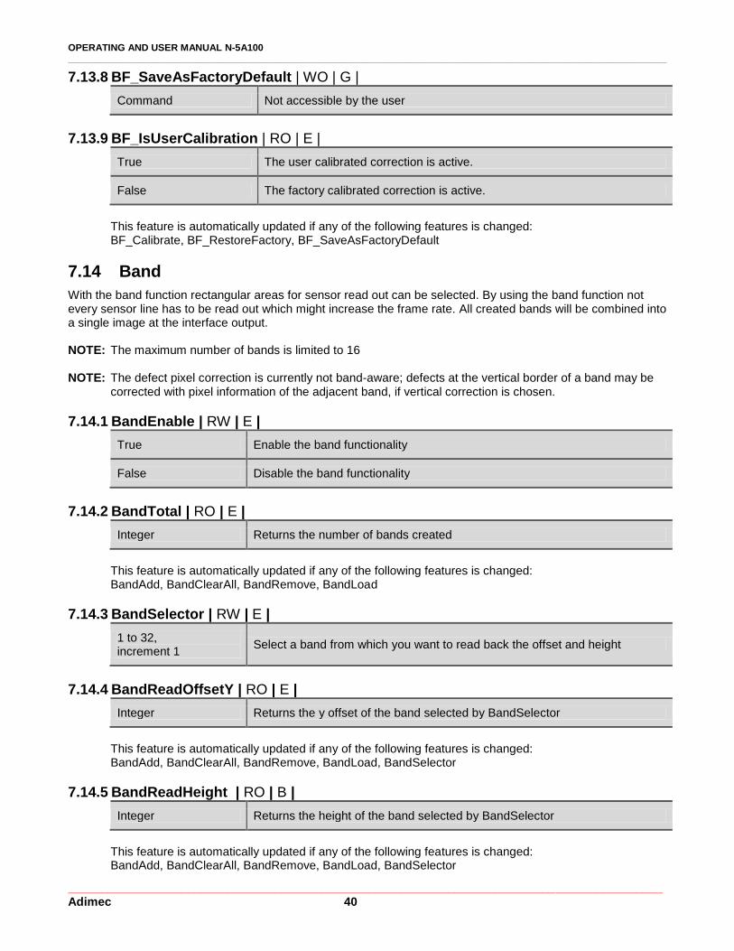
7.13.8 BF_SaveAsFactoryDefault | WO | G |
Command Not accessible by the user
7.13.9 BF_IsUserCalibration | RO | E |
True The user calibrated correction is active.
False The factory calibrated correction is active.
This feature is automatically updated if any of the following features is changed: BF_Calibrate, BF_RestoreFactory, BF_SaveAsFactoryDefault
7.14 Band
With the band function rectangular areas for sensor read out can be selected. By using the band function not every sensor line has to be read out which might increase the frame rate. All created bands will be combined into a single image at the interface output. NOTE: The maximum number of bands is limited to 16 NOTE: The defect pixel correction is currently not band-aware; defects at the vertical border of a band may be
corrected with pixel information of the adjacent band, if vertical correction is chosen.
7.14.1 BandEnable | RW | E |
True Enable the band functionality
False Disable the band functionality
7.14.2 BandTotal | RO | E |
Integer Returns the number of bands created
This feature is automatically updated if any of the following features is changed: BandAdd, BandClearAll, BandRemove, BandLoad
7.14.3 BandSelector | RW | E |
1 to 32, increment 1
Select a band from which you want to read back the offset and height
7.14.4 BandReadOffsetY | RO | E |
Integer Returns the y offset of the band selected by BandSelector
This feature is automatically updated if any of the following features is changed: BandAdd, BandClearAll, BandRemove, BandLoad, BandSelector
7.14.5 BandReadHeight | RO | B |
Integer Returns the height of the band selected by BandSelector
This feature is automatically updated if any of the following features is changed: BandAdd, BandClearAll, BandRemove, BandLoad, BandSelector
OPERATING AND USER MANUAL N-5A100 ________________________________________________________________________________________________________________
_________________________________________________________________________________________ Adimec 41
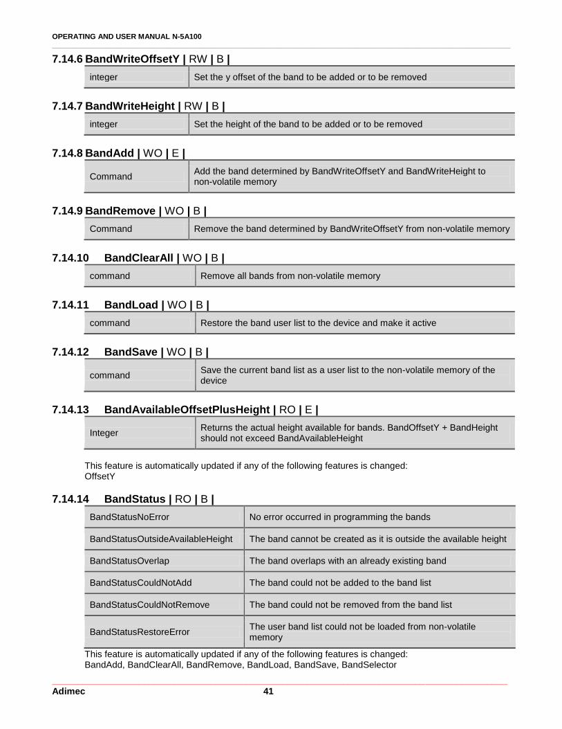
7.14.6 BandWriteOffsetY | RW | B |
integer Set the y offset of the band to be added or to be removed
7.14.7 BandWriteHeight | RW | B |
integer Set the height of the band to be added or to be removed
7.14.8 BandAdd | WO | E |
Command Add the band determined by BandWriteOffsetY and BandWriteHeight to non-volatile memory
7.14.9 BandRemove | WO | B |
Command Remove the band determined by BandWriteOffsetY from non-volatile memory
7.14.10 BandClearAll | WO | B |
command Remove all bands from non-volatile memory
7.14.11 BandLoad | WO | B |
command Restore the band user list to the device and make it active
7.14.12 BandSave | WO | B |
command Save the current band list as a user list to the non-volatile memory of the device
7.14.13 BandAvailableOffsetPlusHeight | RO | E |
Integer Returns the actual height available for bands. BandOffsetY + BandHeight should not exceed BandAvailableHeight
This feature is automatically updated if any of the following features is changed: OffsetY
7.14.14 BandStatus | RO | B |
BandStatusNoError No error occurred in programming the bands
BandStatusOutsideAvailableHeight The band cannot be created as it is outside the available height
BandStatusOverlap The band overlaps with an already existing band
BandStatusCouldNotAdd The band could not be added to the band list
BandStatusCouldNotRemove The band could not be removed from the band list
BandStatusRestoreError The user band list could not be loaded from non-volatile memory
This feature is automatically updated if any of the following features is changed: BandAdd, BandClearAll, BandRemove, BandLoad, BandSave, BandSelector
OPERATING AND USER MANUAL N-5A100 ________________________________________________________________________________________________________________
_________________________________________________________________________________________ Adimec 42
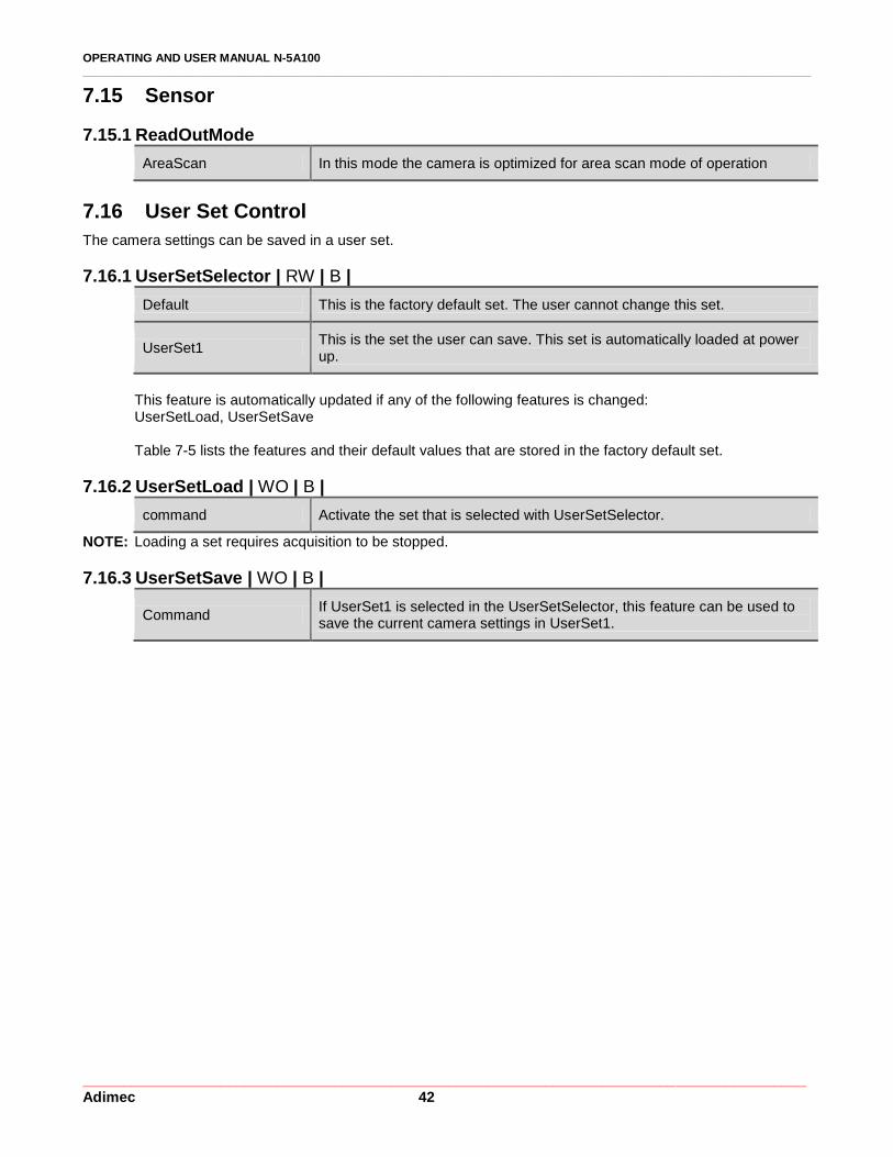
7.15 Sensor
7.15.1 ReadOutMode
AreaScan In this mode the camera is optimized for area scan mode of operation
7.16 User Set Control
The camera settings can be saved in a user set.
7.16.1 UserSetSelector | RW | B |
Default This is the factory default set. The user cannot change this set.
UserSet1 This is the set the user can save. This set is automatically loaded at power up.
This feature is automatically updated if any of the following features is changed: UserSetLoad, UserSetSave Table 7-5 lists the features and their default values that are stored in the factory default set.
7.16.2 UserSetLoad | WO | B |
command Activate the set that is selected with UserSetSelector.
NOTE: Loading a set requires acquisition to be stopped.
7.16.3 UserSetSave | WO | B |
Command If UserSet1 is selected in the UserSetSelector, this feature can be used to save the current camera settings in UserSet1.

OPERATING AND USER MANUAL N-5A100 ________________________________________________________________________________________________________________
_________________________________________________________________________________________ Adimec 43
Table 7-5: A list of the default values for the features that can be stored with UserSetSave
Group Register Default Remark
DeviceControl DeviceUserID <empty>
DeviceIndicatorMode Active
ImageFormatControl Width 2592
Height 2048
OffsetX 0
OffsetY 0
BinningHorizontal 1
BinningVertical 1
BinningMode Sum
ReverseX 0
ReverseY 0
PixelFormat Mono8
TestImageSelector 0
TestImageVideoLevel 0
CrossHairOverlay 0
FrameCounterOverlay 0
AcquisitionControl AcquisitionFramePeriodRaw 100000 10 fps
TriggerSource Trigger
TriggerActivation RisingEdge
ExposureMode Timed
ExposureTimeRaw 5000
InterfaceUtilization 100
AnalogControl GainSelector All
GainRaw 1000 1x
BlackLevelRaw 20
LUTControl LUTEnable 0
DefectPixel DefectPixelCorrectionEnable 1
DefectPixelTestMode Off
DarkField DF_ColumnOffsetCorrection 1
BrightField BF_ColumnGainCorrection 1
BF_AutoLevelAdjust 0
BF_CalibrationVideoLevel 40 %
BF_OutputImagesDuringCalibration 0
Band BandEnable 0
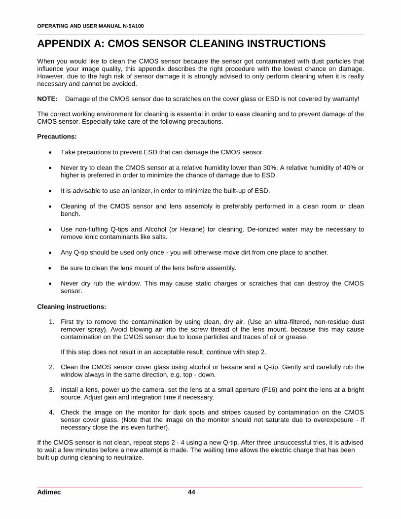
OPERATING AND USER MANUAL N-5A100 ________________________________________________________________________________________________________________
_________________________________________________________________________________________ Adimec 44
APPENDIX A: CMOS SENSOR CLEANING INSTRUCTIONS
When you would like to clean the CMOS sensor because the sensor got contaminated with dust particles that influence your image quality, this appendix describes the right procedure with the lowest chance on damage. However, due to the high risk of sensor damage it is strongly advised to only perform cleaning when it is really necessary and cannot be avoided. NOTE: Damage of the CMOS sensor due to scratches on the cover glass or ESD is not covered by warranty! The correct working environment for cleaning is essential in order to ease cleaning and to prevent damage of the CMOS sensor. Especially take care of the following precautions. Precautions:
Take precautions to prevent ESD that can damage the CMOS sensor.
Never try to clean the CMOS sensor at a relative humidity lower than 30%. A relative humidity of 40% or higher is preferred in order to minimize the chance of damage due to ESD.
It is advisable to use an ionizer, in order to minimize the built-up of ESD.
Cleaning of the CMOS sensor and lens assembly is preferably performed in a clean room or clean bench.
Use non-fluffing Q-tips and Alcohol (or Hexane) for cleaning. De-ionized water may be necessary to remove ionic contaminants like salts.
Any Q-tip should be used only once - you will otherwise move dirt from one place to another.
Be sure to clean the lens mount of the lens before assembly.
Never dry rub the window. This may cause static charges or scratches that can destroy the CMOS sensor.
Cleaning instructions:
1. First try to remove the contamination by using clean, dry air. (Use an ultra-filtered, non-residue dust remover spray). Avoid blowing air into the screw thread of the lens mount, because this may cause contamination on the CMOS sensor due to loose particles and traces of oil or grease. If this step does not result in an acceptable result, continue with step 2.
2. Clean the CMOS sensor cover glass using alcohol or hexane and a Q-tip. Gently and carefully rub the window always in the same direction, e.g. top - down.
3. Install a lens, power up the camera, set the lens at a small aperture (F16) and point the lens at a bright source. Adjust gain and integration time if necessary.
4. Check the image on the monitor for dark spots and stripes caused by contamination on the CMOS
sensor cover glass. (Note that the image on the monitor should not saturate due to overexposure - if necessary close the iris even further).
If the CMOS sensor is not clean, repeat steps 2 - 4 using a new Q-tip. After three unsuccessful tries, it is advised to wait a few minutes before a new attempt is made. The waiting time allows the electric charge that has been built up during cleaning to neutralize.