operating instruction 42/13-23-en rev. b control valve 23 ... · operating instruction 42/13-23-en...
TRANSCRIPT

Operating Instruction 42/13-23-EN Rev. B
Control Valve 23 / 24 Single-seat straight-way valve DN 15 to 100 with exchangeable seat ring, with pneumatic actuator

2 42/13-23-EN Rev. B | Control Valve 23 / 24
Short product description The single-seat straight-way valve 23 / 24 is a final control element for continuous control through variation of the media or energy flow in tubes.
Manufacturer ABB Automation Products GmbH Process Automation Borsigstr. 2 63755 Alzenau Germany Tel: +49 551 905-534 Fax: +49 551 905-555 Customer service center Tel.: +49 180 5 222 580 Fax: +49 621 381 931-29031 [email protected]

Control Valve 23 / 24 | 42/13-23-EN Rev. B 3
Change from one to two columns
Contents
1 Safety ............................................................................... 4 1.1 General information and notes for the reader ........ 4 1.2 Warnings ............................................................. 4 1.3 Intended use ........................................................ 4 1.4 Improper use ....................................................... 4 1.5 Warranty provisions ............................................. 4
2 Brief description .............................................................. 5
3 Installation ....................................................................... 6 3.1 General information .............................................. 6 3.2 Scope of delivery ................................................. 6 3.3 Installation ........................................................... 6 3.3.1 Operating conditions at the installation site ........... 6 3.3.2 Tube-mounting the valve ...................................... 6
4 Commissioning ................................................................ 7
5 Maintenance .................................................................... 8 5.1 General instructions ............................................. 8 5.2 Maintenance works / Conversion ......................... 8 5.2.1 Changing the actuator action ............................... 8 5.2.2 Replacing the diaphragm (13) in the actuator ....... 9 5.2.3 Replacing / adding pressure springs (14) in the
actuator ............................................................... 9 5.2.4 Replacing the stem seal (3) in the actuator ......... 10 5.2.5 Replacing the stuffing box packing (156) of the
stem seal in the control valve ............................. 10 5.2.6 Checking and, if required, replacing the valve seat
(20) and cone (26) .............................................. 11
6 Specifications ................................................................ 12 6.1 Valve housing .................................................... 12 6.2 Internal trim ........................................................ 12 6.3 Stem seal .......................................................... 12 6.4 Actuator ............................................................ 12 6.5 Accessories ....................................................... 12 6.5.1 Overwiew: DN – Kvs value – actuator size –
differential pressure at cone ............................... 13
7 Dimensions .................................................................... 14
8 Sectional diagrams ....................................................... 15 8.1 Actuator ............................................................ 15 8.2 Stem coupling with stroke indicator ................... 15 8.3 control valve ...................................................... 16

4 42/13-23-EN Rev. B | Control Valve 23 / 24
1 Safety Change from one to two columns
1.1 General information and notes for the reader
These instructions are an important part of the product and must be retained for future reference. Installation, commissioning, and maintenance of the product may only be performed by trained specialist personnel who have been authorized by the plant operator accordingly. The specialist personnel must have read and understood the manual and must comply with its instructions. For additional information or if specific problems occur that are not discussed in these instructions, contact the manufacturer. The content of these instructions is neither part of nor an amendment to any previous or existing agreement, promise or legal relationship. Modifications and repairs to the product may only be performed if expressly permitted by these instructions. Information and symbols on the product must be observed. These may not be removed and must be fully legible at all times. The operating company must strictly observe the applicable national regulations relating to the installation, function testing, repair and maintenance of electrical products.
1.2 Warnings
The warnings in these instructions are structured as follows:
DANGER The signal word "DANGER" indicates an imminent danger. Failure to observe this information will result in death or severe injury.
WARNING
The signal word "WARNING" indicates an imminent danger. Failure to observe this information may result in death or severe injury.
CAUTION
The signal word "CAUTION" indicates an imminent danger. Failure to observe this information may result in minor or moderate injury.
NOTE
The signal word "NOTE" indicates useful or important information about the product. The signal word "NOTE" is not a signal word indicating a danger to personnel. The signal word "NOTE" can also refer to material damage.
1.3 Intended use The single-seat straight-way valve 23 / 24 is a final control element for continuous control through variation of the media or energy flow in tubes. 1.4 Improper use The following are considered to be instances of improper use of the device: — As a climbing aid, e.g., for mounting purposes. — As a support for external loads, e.g., as a support for
piping, etc. — Adding material, e.g., by painting over the name plate or
welding / soldering on parts. — Removing material, e.g., by spot drilling the housing. 1.5 Warranty provisions
Using the device in a manner that does not fall within the scope of its intended use, disregarding this manual, using underqualified personnel, or making unauthorized alterations releases the manufacturer from liability for any resulting damage. This renders the manufacturer's warranty null and void.

Control Valve 23 / 24 | 42/13-23-EN Rev. B 5
2 Brief description
The single-seat straight-way valve 23 / 24 is a final control element for continuous control through variation of the media or energy flow in tubes. Actuation is through compressed air from a multispring diaphragm actuator. Valve housings of different nominal diameters, pressure levels, materials and internal trims (seat/cone assemblies) are available to enable optimum adaptation to the operating data. Additionally, different Kvs values are possible. A special feature of 23 / 24 control valves is the design and mounting of the seat ring. Instead of a screw-type seat ring, a laid-in one is used, which can be exchanged easily. And the ring is symmetric and can be used from both sides. Simply turn it by 180°.Usually, a maintenance-free double seal with PTFE lip rings and a profiled fine seal is used for the valve stem. A pure graphite / Inconel packing with adjustable pressing and a hermetic bellows seal are optionally available.
The multi-spring diaphragm actuator combines a compact design with a low height. The valve is actuated through compressed air of max. 6 bar, and returned by spring force. Adaptation to the necessary positioning forces is possible through different actuator sizes (diameters) and the number of return springs used. The following two valve actions are possible: Air to open / spring force to close and Air to close / spring force to open. The valve and the actuator need to be fitted with a positioner for controlling the position between 0 ... 100 %. The positioner and the diaphragm actuator form an integral unit. A follower pin allows for mechanical stroke measurement free of play. The point for stroke measurement is inside the yoke and protected by it. Therefore, this design complies with the regulations for the prevention of accidents. The air flow is guided through a channel bore inside the yoke.
Change from two to one column
Parabolic cone,
seat ring with metallic seal
Parabolic cone,
seat ring with soft seal (PTFE)
Slotted cone,
seat ring with metallic seal
Parabolic cone, guided at the bottom,
seat ring with metallic seal
Fig. 1: Internal trims
PTFE-ringe with profiled fine seal,
maintenance free
Pure graphite packing,
adjustable pressing
Bellows seal,
hermetic
Fig. 2: Stem seal
Change from one to two columns
M10933
M10932

6 42/13-23-EN Rev. B | Control Valve 23 / 24
3 Installation
3.1 General information Proper and safe operation of the control valve 23 / 24 requires proper transportation and storage, installation and commissioning by qualified personnel, correct operation and careful maintenance. Only qualified persons who are familiar with the installation, commissioning, operation and maintenance of these valves are allowed to work on them Observe: — these operating instructions, — the relevant safety regulations and standards pertaining to
the installation and operation of systems in which the control valve 23 / 24 is used.
The control valve 23 / 24 has been manufactured and tested in accordance with the applicable regulations, standards and directives and has been delivered in a safe condition. These operating instructions contain warnings and cautions marked with the symbol . The instructions given in these sections must be observed to retain the device in a safe condition and to ensure safe operation. Otherwise, persons can be endangered or the device itself or other devices or equipment may be damaged or fail. If you should need information that is not contained in the present operating instructions please do not hesitate to contact us.
3.2 Scope of delivery Check the shipment (items and scope of delivery) immediately upon arrival to see if it is in accordance with your order. Normally, the valve is delivered with the positioner (required for operation) and the optionally available handwheel already mounted.
3.3 Making the pneumatic connection to the actuator or positioner
The positioner mounted to the actuator must be supplied with compressed air. Refer to the positioner rating plate and the operating instructions delivered with the positioner for details about the appropriate lines for the air supply and the positioning signal.
3.4 Installation
NOTE
Before mounting check to ensure that the specifications in terms of safety and control applicable to the control valve 23 / 24 will not be exceeded.
3.4.1 Operating conditions at the installation site Medium / pressure / temperature depending on the material (housing, internal trim, valve stem seal) and the pressure rating Climate class JQE to DIN 40040 Ambient temperature -10...+80 °C Relative humidity <75 %, (95% if for a short time); exceptional, minor condensation Protection IP 65 Mounting orientation preferably with actuator in vertical, up-oriented position 3.4.2 Tube-mounting the valve See chapter „Dimensions“ on page 14 for dimensions. The control valve 23 / 24 is provided with EN1092-1 type flanges for pressure ratings PN 16, 25 or 40 (depending on the ordered model). When mounting the valve, pay special attention to the arrow on the housing, indicating the flow direction. Make sure that the mounted valve is held by the tube, only. Using additional material for fastening the valve to the actuator is not permitted. Control valves are flow restrictors. Their flow-restricting parts (i.e. seat/cone assembly) are exposed to media with high flow rates. To protect these sensitive parts from being damaged, it is absolutely necessary to place a dirt trap in the tube, directly upstream of the valve. Use a funnel-shaped adapter if the nominal diameter (DN) of the tube should not match that of the valve. Do not connect any devices into the tube nor branch the tube over a length of 10 x the nominal diameter upstream and downstream of the valve.

Control Valve 23 / 24 | 42/13-23-EN Rev. B 7
It is recommended to provide a bypass line with the corresponding shut-off valves. The control valve 23/24 can be easily removed for maintenance work then, without impairing the process. Preferably mount the control valve in a horizontal tube, with the actuator up-oriented and in vertical position. Other mounting orientations should only be chosen exceptionally, since they will increase the wear (e.g. of the valve stem). Prior to mounting the valve in a newly installed tube always carefully clean the tube by pickling and rinsing. When choosing the valve mounting location always take into consideration the valve weight and dimensions and that there has to be sufficient space to allow for possible later maintenance work.
Always fasten the flange screws cross-wise, and with the appropriate torque specified below: — 30 Nm for M 12 screws — 70 Nm for M 16 screws — 100 Nm for M 20 screws Usually, the valve is delivered with the positioner already mounted. If, however, this is not the case for any reason, follow the mounting instructions in the positioner manual.
Note — Prior to mounting the valve in a newly installed tube,
always carefully clean the tube by pickling and rinsing . — Observe the arrow on the valve housing, indicating the
flow direction. — Make sure that the mounted control valve is held by the
tube, only. Do not use additional mounting material to fasten the valve to the actuator.
— Insert a dirt trap in the tube, dirctly upstream of the valve.
— Preferably mount the control valve in a horizontal tube, with the actuator up-oriented and in vertical position.
Change from two to one column Change from one to two columns
4 Commissioning
After the control valve has been mounted to the tube and connected properly to the positioner, the control valve can be commissioned without requiring any further steps.
Note Slowly heat the valve until reaching the specified operating temperature. Avoid temperature shocks. Make sure that the flange connection is tight. If required, re-fasten the screws (cross-wise). When using control valves with pure graphite / inconel packing, re-adjust the pressing of the packing directly upon commissioning.

8 42/13-23-EN Rev. B | Control Valve 23 / 24
5 Maintenance
5.1 General instructions Check the items listed below, and readjust, replace or repair if required: 1. Check the positioner for proper position control within the
range of 0 ... 100 %. If unpermissible deviations occur, readjust the positioner. Follow the relevant instructions in the positioner manual.
2. Check the valve stem for proper sealing. When using maintenance-free double seals made up of PTFE rings and a profiled fine seal, the seal needs to be replaced when is becomes is leaky (see chapter „Replacing the stuffing box packing (156) of the stem seal in the control valve“ on page 10) for details. When using a seal with pure graphite / inconel packing, minor leaks can be compensated by readjusting the pressing. If, however, the packing rings are considerably worn, the entire seal needs to be replaced (see chapter „Replacing the stuffing box packing (156) of the stem seal in the control valve“ on page 10) for details.
Note Note that the pressing of the pure graphite / inconel packing causes friction in the stem seal. When increasing the pressing excessively, this may affect the positioning accuracy of the positioner.
When using a valve with bellows seal, leaks can only result from mechanical damage. In this case, the complete bellows seal needs to be replaced (see chapter „Checking and, if required, replacing the valve seat (20) and cone (26)“ on page 11) for details. 3. Check the seat / cone seal for tightness If a leakage should occur that exceeds the tolerances specified in the technical data of this manual, proceed as described below (see chapter „Checking and, if required, replacing the valve seat (20) and cone (26)“ on page 11). — Replace the soft PTFE seal in the seat ring (with soft seat /
cone seal). — Turn the seat ring by 180°, if this has not yet been done
(with metallic seat / cone seal) and set ring symmetrically designed.
— Replace the complete internal trim (seat and cone).
4. Check the valve stem for cleanness Proper positioning through the positioner requires that the valve stem is clean. Remove any deposits (crusts) from the stem. Move the actuator to the upper end position to be able to access the whole valve stem for cleaning.
Note Do not damage the polished valve stem surface. Do not use sharp-edged tools or abrasive paper for cleaning.
5.2 Maintenance works / Conversion The following sections give an overview of the required maintenance works and the possible conversion. Follow the instructions below. Also refer to the sectional drawings of the actuators for details (See chapter „Sectional diagrams“ on page 15). 5.2.1 Changing the actuator action (see chapter „Sectional diagrams“ on page 15). The action can be changed from “Air to open / spring force to close” to “Air to close / spring force to open” and vice versa. Proceed as described below. Changing from “Air to open / spring force to close” to “Air to close / spring force to open” action 1. Switch off the air supply to the positioner. 2. Remove the spray protection cap (41). 3. Remove the screw plug (29) from connection Z2. 4. Remove the screw plug (39) with its seal (38) from the
spring cover (15). 5. Access the hexagon nut (18) through the open half of the
cover (15) and remove it from the stem (1). 6. Remove the male pipe fitting (4) with its seal (6) from the
cover half (9). 7. Remove the complete diaphram actuator, turn by 180°,
and replace. 8. Proceed in reverse order to remount. Additionally make
the necessary external tubing (43) between connections Z2 and Z3.
Control Valve 23 / 24 | 42/13-23-EN Rev. B 9
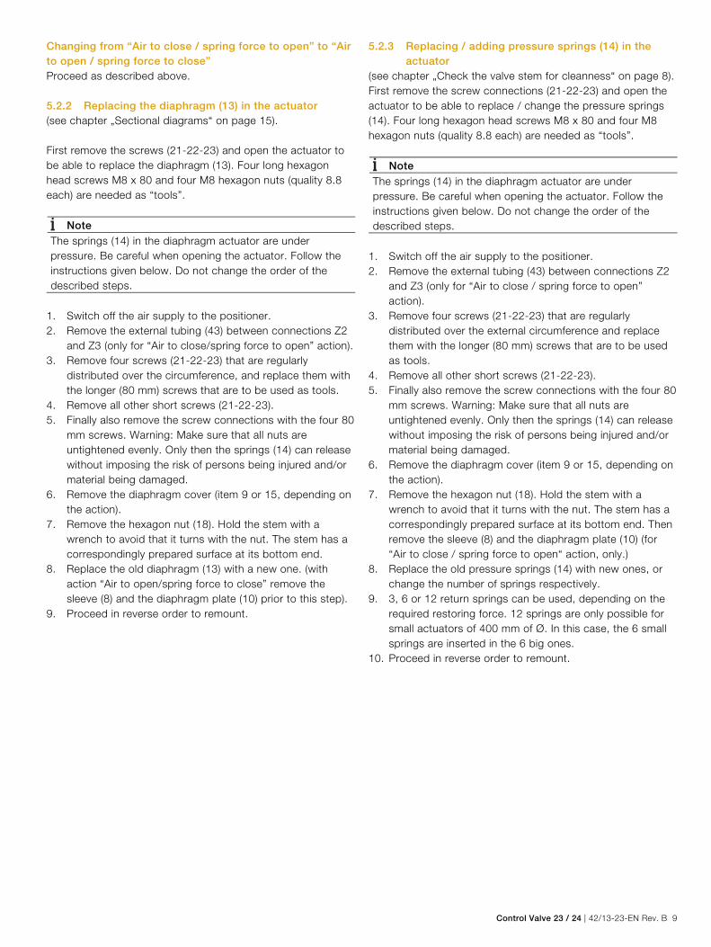
Changing from “Air to close / spring force to open” to “Air to open / spring force to close” Proceed as described above. 5.2.2 Replacing the diaphragm (13) in the actuator (see chapter „Sectional diagrams“ on page 15). First remove the screws (21-22-23) and open the actuator to be able to replace the diaphragm (13). Four long hexagon head screws M8 x 80 and four M8 hexagon nuts (quality 8.8 each) are needed as “tools”.
Note The springs (14) in the diaphragm actuator are under pressure. Be careful when opening the actuator. Follow the instructions given below. Do not change the order of the described steps.
1. Switch off the air supply to the positioner. 2. Remove the external tubing (43) between connections Z2
and Z3 (only for “Air to close/spring force to open” action). 3. Remove four screws (21-22-23) that are regularly
distributed over the circumference, and replace them with the longer (80 mm) screws that are to be used as tools.
4. Remove all other short screws (21-22-23). 5. Finally also remove the screw connections with the four 80
mm screws. Warning: Make sure that all nuts are untightened evenly. Only then the springs (14) can release without imposing the risk of persons being injured and/or material being damaged.
6. Remove the diaphragm cover (item 9 or 15, depending on the action).
7. Remove the hexagon nut (18). Hold the stem with a wrench to avoid that it turns with the nut. The stem has a correspondingly prepared surface at its bottom end.
8. Replace the old diaphragm (13) with a new one. (with action “Air to open/spring force to close” remove the sleeve (8) and the diaphragm plate (10) prior to this step).
9. Proceed in reverse order to remount.
5.2.3 Replacing / adding pressure springs (14) in the actuator
(see chapter „Check the valve stem for cleanness“ on page 8). First remove the screw connections (21-22-23) and open the actuator to be able to replace / change the pressure springs (14). Four long hexagon head screws M8 x 80 and four M8 hexagon nuts (quality 8.8 each) are needed as “tools”.
Note The springs (14) in the diaphragm actuator are under pressure. Be careful when opening the actuator. Follow the instructions given below. Do not change the order of the described steps.
1. Switch off the air supply to the positioner. 2. Remove the external tubing (43) between connections Z2
and Z3 (only for “Air to close / spring force to open” action).
3. Remove four screws (21-22-23) that are regularly distributed over the external circumference and replace them with the longer (80 mm) screws that are to be used as tools.
4. Remove all other short screws (21-22-23). 5. Finally also remove the screw connections with the four 80
mm screws. Warning: Make sure that all nuts are untightened evenly. Only then the springs (14) can release without imposing the risk of persons being injured and/or material being damaged.
6. Remove the diaphragm cover (item 9 or 15, depending on the action).
7. Remove the hexagon nut (18). Hold the stem with a wrench to avoid that it turns with the nut. The stem has a correspondingly prepared surface at its bottom end. Then remove the sleeve (8) and the diaphragm plate (10) (for “Air to close / spring force to open“ action, only.)
8. Replace the old pressure springs (14) with new ones, or change the number of springs respectively.
9. 3, 6 or 12 return springs can be used, depending on the required restoring force. 12 springs are only possible for small actuators of 400 mm of Ø. In this case, the 6 small springs are inserted in the 6 big ones.
10.Proceed in reverse order to remount.

10 42/13-23-EN Rev. B | Control Valve 23 / 24
5.2.4 Replacing the stem seal (3) in the actuator (see chapter „Sectional diagrams“ on page 15). To be able to replace the stem seal first disconnect the actuator from the valve. In the home position (i.e. air evacuated from diaphragm chamber) the pressure springs (14) are under prepressure and press the control cone (26) against the stop. Dismounting is only possible when the actuator has been moved away from the stop by the positioner. 1. Start the positioner and move the control valve to any
position between 0 … 100 %. 2. Disconnect the stem at the stem coupling. 3. Undo the actuator / valve connection and remove
theactuator. (When using DN 15 ... 65 valves remove the 4 screws (80), when using a DN 80 and DN 100 valve remove thegroove nut (150)).
4. Stop the positioner and remove it from the actuator. 5. Remove the upper half of the stem coupling from the
actuator stem. 6. Remove the two set screws (2) from the stem. 7. Remove the guide bushing (4) with its seal (3) and slide
bearing (5) from the actuator. 8. Replace the old seal (3) and the old slide bearing (5) in the
guide bushing (4) with new ones. 9. Proceed in reverse order to remount. 5.2.5 Replacing the stuffing box packing (156) of the
stem seal in the control valve (see chapter „control valve“ on page 16). To be able to replace the stuffing box packing first disconnect the actuator from the valve. In the home position (i.e. air evacuated from diaphragm chamber) the pressure springs (14) are under prepressure and press the control cone (26) against the stop. Dismounting is only possible when the actuator has been moved away from the stop bythe positioner.
1. Start the positioner and move the control valve to any position between 0 … 100 %.
2. Disconnect the stem at the stem coupling. 3. Undo the actuator/valve connection and remove the
actuator. (When using DN 15 ... 65 valves remove the 4 screws (80), when using a DN 80 + DN 100 valve remove the groove nut (150)).
4. Remove the lower half of the stem coupling from the control valve stem.
5. Remove the cover flange (2) with the valve stem (50) and the cone (26) from the housing. (When using DN 80 + 100 valves first undo the screws (80)).
6. Remove the stuffing box screw (152). 7. Remove the stem (50) with the cone (26) from the cover
flange (2). 8. Remove the old stuffing box packing. Clean the chamber,
especially the walls. 9. Place the new stuffing box packing in the proper position. Also replace the following parts with new ones With PTFE ring seal
Item 156 Complete packing set, consisting of:
— PFTE collars
— Supporting rings
— Helical spring
— Profiled fine seal
Item 166 O-ring seal
With pure graphite packing
Item 154 Neck rings, 2 pieces,
1x for top and 1x for bottom
Item 156 Complete packing set
consisting of individual graphite rings
10.Proceed in reverse order to remount.
Note Prior to dismounting first check the valve stem for desposits, and clean if required (see chapter „Check the valve stem for cleanness“ on page 8). Before inserting new packing rings carefully clean the chamber, especially the walls.

Control Valve 23 / 24 | 42/13-23-EN Rev. B 11
5.2.6 Checking and, if required, replacing the valve seat (20) and cone (26)
(see chapter „control valve“ on page 16). To be able to check / replace the valve seat and cone first disconnect the actuator from the valve. In the home position (i.e. air evacuated from diaphragm chamber) the pressure springs (14) are under prepressure and press the control cone (26) against the stop. Dismounting is only possible when the actuator has been moved away from the stop by the positioner. 1. Start the positioner and move the control vave to any
position between 0 and 100 %. 2. Disconnect the stem at the stem coupling. 3. Undo the actuator / valve connection and remove the
actuator. (When using DN 15 ... 65 valves remove the 4 screws (80), when using a DN 80 or DN 100 valve remove the groove nut (150)).
4. Remove the lower half of the stem coupling from the control valve stem.
5. Remove the cover flange (2) with the valve stem (50) and cone (26) from the housing. When using valves of nominal diameter DN 80 and DN 100 first remove the screws (80). When using a valve with bellows seal also remove the screws (80) fastening the cover flange to the intermediate flange (2/6) and the intermediate flange to the housing (6/1).
6. You can access the seat and cone then and perform various steps:
— Check the seals for damage. — Turn the seat ring by 180° to use the unworn side. — Replace the soft PTFE seal in the seat ring. — Completely replace the seat and cone if they are
damaged, if you want to change over to another KVs value, or if another internal trim is to be used (e. g. slotted cone). Note that the cone (26) can only be replaced together with the valve stem (50) or with the bellows seal (142), respectively.
7. Proceed in reverse order to remount.

12 42/13-23-EN Rev. B | Control Valve 23 / 24
6 Specifications
6.1 Valve housing Type Single-seat straight-way valve Material Housing Material Pressure
rating
TSmin TSmax
Cast steel
GP240GH
1.0619 PN 40 -10 °C
(14 °F)
400 °C
(752 °F)
Stainless steel
G-X5CrNiMo 19 11 2
1.4408 PN 40 -29 °C
(-20 °F)
400 °C
(752 °F)
Size DN 15 - 25 - 32 - 40 - 50 - 65 - 80 - 100 Connector Flanges for cast steel and stainless steel housing — PN 16 (EN1092-1), PN 25 (EN1092-1), PN 40 (EN1092-1), Sealing surface form B1
6.2 Internal trim
Control cone — Parabolic cone, — Parabolic cone, guided at the bottom, — Slotted cone Seat ring Laid-in, easily exchangeable can be used from both sides (can be turned by 180°) with metallic or soft seal (optional), (soft seal made of PTFE, max. 200 °C). Characteristic curve Linear or equal percentage Kvs value See capter „Overwiew: DN – Kvs value – actuator size – differential pressure at cone“ on page 13. Material Cone Seat ring Seal
Parabolic 1.4571 1.4571 metallic
Parabolic 1.4571 1.4571 PTFE
Parabolic 1.4112 hardened 1.4112 hardened metallic
parabolic1) 1.4571 1.4571 metallic
slotted cone 1.4571 1.4571 nitrated metallic 1) Parabolic cone, guided at the bottom
Setting ratio 40:1 Leakage (the percentages are relative to the Kvs value) — < 0.01 % or Class VI to IEC 534 (with metallic seal), — < 0.0001 % or Class IV to IEC 534 (with soft seal made of PTFE)
6.3 Stem seal
Standard Maintenance-free double seal, with PTFE ring seals and profiled fine seal, for temperatures up to max. 180 °C (356 °F). Optional Pure graphite / inconel packing, adjustable pressing, for temperatures up to 400 °C (752 °F) or Stainless steel bellows seal, hermetic, for temperatures up to max. 200 °C (392 °F). 6.4 Actuator Type Compact multi-spring diaphragm actuator, Size Ø 270 mm (10,62 inch) and 400 mm (15,74 inch), with 3 - 6 - 12 return springs in the actuator. Material Chromated steel powder-coated blue (RAL 5015). Actuation Compressed air, 6 bar (87,02 psi), Spring return Action (referred to valve positioning) Reversible, Air to open / spring force to close Air to close / spring force to open Actuator stem Stainless steel 1.4122 Yoke Spheroid graphite cast iron GGG 40, powder-coated blue (RAL 5015), for special integral mounting of a positioner with internal air connections, no external tubing required (lateral mounting to DIN/IEC 534 also possible). 6.5 Accessories Positioner For integral mounting to control valve 23 / 24 (see separate data sheet for type and ordering details). Handwheel For manual adjustment of the control valve, mounted to the actuator, made of stainless steel.
Control Valve 23 / 24 | 42/13-23-EN Rev. B 13
Change from two to one column
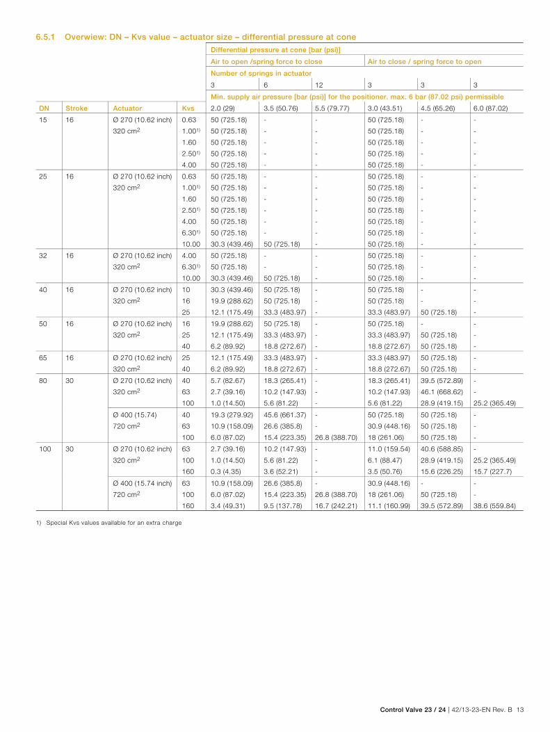
6.5.1 Overwiew: DN – Kvs value – actuator size – differential pressure at cone
Differential pressure at cone [bar (psi)]
Air to open /spring force to close Air to close / spring force to open
Number of springs in actuator
3 6 12 3 3 3
Min. supply air pressure [bar (psi)] for the positioner. max. 6 bar (87.02 psi) permissible
DN Stroke Actuator Kvs 2.0 (29) 3.5 (50.76) 5.5 (79.77) 3.0 (43.51) 4.5 (65.26) 6.0 (87.02)
15 16 Ø 270 (10.62 inch)
320 cm2
0.63
1.001)
1.60
2.501)
4.00
50 (725.18)
50 (725.18)
50 (725.18)
50 (725.18)
50 (725.18)
-
-
-
-
-
-
-
-
-
-
50 (725.18)
50 (725.18)
50 (725.18)
50 (725.18)
50 (725.18)
-
-
-
-
-
-
-
-
-
-
25 16 Ø 270 (10.62 inch)
320 cm2
0.63
1.001)
1.60
2.501)
4.00
6.301)
10.00
50 (725.18)
50 (725.18)
50 (725.18)
50 (725.18)
50 (725.18)
50 (725.18)
30.3 (439.46)
-
-
-
-
-
-
50 (725.18)
-
-
-
-
-
-
-
50 (725.18)
50 (725.18)
50 (725.18)
50 (725.18)
50 (725.18)
50 (725.18)
50 (725.18)
-
-
-
-
-
-
-
-
-
-
-
-
-
-
32 16 Ø 270 (10.62 inch)
320 cm2
4.00
6.301)
10.00
50 (725.18)
50 (725.18)
30.3 (439.46)
-
-
50 (725.18)
-
-
-
50 (725.18)
50 (725.18)
50 (725.18)
-
-
-
-
-
-
40 16 Ø 270 (10.62 inch)
320 cm2
10
16
25
30.3 (439.46)
19.9 (288.62)
12.1 (175.49)
50 (725.18)
50 (725.18)
33.3 (483.97)
-
-
-
50 (725.18)
50 (725.18)
33.3 (483.97)
-
-
50 (725.18)
-
-
-
50 16 Ø 270 (10.62 inch)
320 cm2
16
25
40
19.9 (288.62)
12.1 (175.49)
6.2 (89.92)
50 (725.18)
33.3 (483.97)
18.8 (272.67)
-
-
-
50 (725.18)
33.3 (483.97)
18.8 (272.67)
-
50 (725.18)
50 (725.18)
-
-
-
65 16 Ø 270 (10.62 inch)
320 cm2
25
40
12.1 (175.49)
6.2 (89.92)
33.3 (483.97)
18.8 (272.67)
-
-
33.3 (483.97)
18.8 (272.67)
50 (725.18)
50 (725.18)
-
-
80 30 Ø 270 (10.62 inch)
320 cm2
40
63
100
5.7 (82.67)
2.7 (39.16)
1.0 (14.50)
18.3 (265.41)
10.2 (147.93)
5.6 (81.22)
-
-
-
18.3 (265.41)
10.2 (147.93)
5.6 (81.22)
39.5 (572.89)
46.1 (668.62)
28.9 (419.15)
-
-
25.2 (365.49)
Ø 400 (15.74)
720 cm2
40
63
100
19.3 (279.92)
10.9 (158.09)
6.0 (87.02)
45.6 (661.37)
26.6 (385.8)
15.4 (223.35)
-
-
26.8 (388.70)
50 (725.18)
30.9 (448.16)
18 (261.06)
50 (725.18)
50 (725.18)
50 (725.18)
-
-
-
100 30 Ø 270 (10.62 inch)
320 cm2
63
100
160
2.7 (39.16)
1.0 (14.50)
0.3 (4.35)
10.2 (147.93)
5.6 (81.22)
3.6 (52.21)
-
-
-
11.0 (159.54)
6.1 (88.47)
3.5 (50.76)
40.6 (588.85)
28.9 (419.15)
15.6 (226.25)
-
25.2 (365.49)
15.7 (227.7)
Ø 400 (15.74 inch)
720 cm2
63
100
160
10.9 (158.09)
6.0 (87.02)
3.4 (49.31)
26.6 (385.8)
15.4 (223.35)
9.5 (137.78)
-
26.8 (388.70)
16.7 (242.21)
30.9 (448.16)
18 (261.06)
11.1 (160.99)
-
50 (725.18)
39.5 (572.89)
-
-
38.6 (559.84) 1) Special Kvs values available for an extra charge

14 42/13-23-EN Rev. B | Control Valve 23 / 24
7 Dimensions
Fig. 3
Size
DN
Actuat.Ø A
[mm (inch)]
Flange [mm (inch)] Overall height [mm (inch)] Weight
[kg (lb)] L
[mm (inch)]
PN Ø D
[mm
(inch)]
Ø k
[mm
(inch)]
No. Ø d
[mm (inch)]
H1 H21) Hh
2)
15 270 (10.62) 130 (5.11) 16/25/40 95 (3.74) 65 (2.55) 4 14 (0.55) 460 (18.11) 574 (22.59) 147
(5.78)
21
(46.29)
25 270 (10.62) 160 (6.29) 16/25/40 115 (4.52) 85 (3.34) 4 14 (0.55) 460 (18.11) 574 (22.59) 147
(5.78)
23
(50.70)
32 270 (10.62) 180 (7.08) 16/25/40 140 (5.51) 100 (3.93) 4 18 (0.7) 460 (18.11) 574 (22.59) 147
(5.78)
24
(52.91)
40 270 (10.62) 200 (7.87) 16/25/40 150 (5.9) 110 (4.33) 4 18 (0.7) 451 (17.75) 579 (22.59) 147
(5.78)
31
(68.34)
50 270 (10.62) 230 (9.05) 16/25/40 165 (6.49) 125 (4.92) 4 18 (0.7) 451 (17.75) 579 (22.59) 147
(5.78)
33
(72.75)
65 270 (10.62) 290 (11.41) 16/25/40 185 (7.28) 145 (5.7) 4
8
18 (0.7) 451 (17.75) 579 (22.59) 147
(5.78)
42
(92.59)
80 270 (10.62)
400 (15.74)
310 (12.20) 16/25/40 200 (7.87) 160 (6.29) 8 18 (0.7) 560 (22.04)
645 (25.39)
769 (30.27)
854 (33.62)
147
(5.78)
162
(6.37)
70
(154.32)
96
(211.64)
100 270 (10.62)
400 (15.74)
350 (13.77) 16/25/40 220 (8.66)
235 (9.25)
180 (7.08)
190 (7.48)
8 18 (0.7)
22 (0.86)
585 (23.03)
670 (26.37)
793 (31.22)
878 (34.56)
147
(5.78)
162
(6.37)
95
(209.43)
120
(264.55) 1) H2 = Overall height with bellows-type stem seal 2) Hh = Handwheel Change from one to two columns
Additional values for weight in kg (lb)
Size DN Bellows-type stem
seal
Actuator with handwheel
Ø A = 270 Ø A = 400
15/25/32 5 6.5 (14.33) -
40/50/65 6 6.5 (14.33) -
80 13 6.5 (14.33) 13 (28.66)
100 13 6.5 (14.33) 13 (28.66)
M10935
A
D k
HH
hH

Control Valve 23 / 24 | 42/13-23-EN Rev. B 15
8 Sectional diagrams
8.1 Actuator
Fig. 4: Air to open / spring force to close
Fig. 5: Air to close / spring force to open
Change from two to one column
1 Stem | 2 Pin | 3 Seal | 4 Bushing | 5 Slide bearing | 6 O-ring seal | 7 Filter | 8 Conversion bushing | 9 9 Diaphragm cover | 10 Diaphragm plate | 13 Diaphragm | 14 Pressure spring | 15 Spring cover | 16 Seal | 17 Protection cap | 18 Hexagon nut | 20 Seal | 21 Hexagon head screw | 22 Plain washer | 23 Hexagon nut | 24 Seal | 25 Screwed bushing | 26 O-ring seal | 27 Cup | 28 O-ring seal | 29 Screw plug | 30 Lever plate | 31 Pan head screw | 32 Crown gear | 33 Hexagon nut | 34 Yoke | 38 Seal | 39 Screw plug | 40 Screwed bushing | 41 Protection cap | 42 Screw plug | 43 Tubing, complete | 45 Backup sleeve1)
1) Only for actuator with Ø 400 mm (15.74 inch)
8.2 Stem coupling with stroke indicator
Fig. 6 1 Hexagon head screw for disconnecting the coupling | 2 Connection side actuator | 3 Connection side valve
16 42/13-23-EN Rev. B | Control Valve 23 / 24
Change from one to two columns
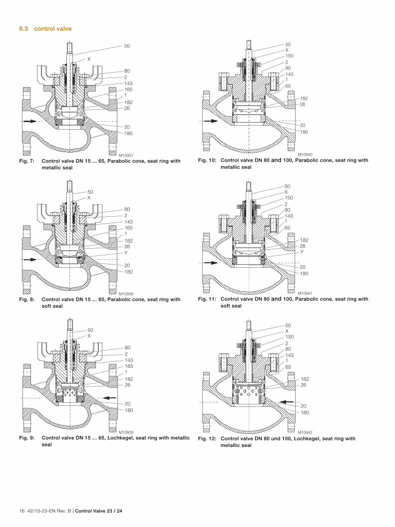
8.3 control valve
Fig. 7: Control valve DN 15 ... 65, Parabolic cone, seat ring with
metallic seal
Fig. 8: Control valve DN 15 ... 65, Parabolic cone, seat ring with
soft seal
Fig. 9: Control valve DN 15 ... 65, Lochkegel, seat ring with metallic
seal
Fig. 10: Control valve DN 80 and 100, Parabolic cone, seat ring with
metallic seal
Fig. 11: Control valve DN 80 and 100, Parabolic cone, seat ring with
soft seal
Fig. 12: Control valve DN 80 und 100, Lochkegel, seat ring with
metallic seal

Control Valve 23 / 24 | 42/13-23-EN Rev. B 17
Fig. 13: Control valve DN 50 and 65, parabolic cone, guided at the
bottom seat ring with metallic seal
Fig. 14: Stem seal (Detail X) A PTFE-ring with profiled fine seal for control valves DN 15 ... 65 | B PTFE-ring with profiled fine seal for control valves DN 80 + 100 | C Pure graphite packing for control valves DN 15 ... 65 | D Pure graphite packing for control valves DN 80 + 100
Fig. 15: Seat ring with PTFE soft seal PTFE (Detail Y)
Fig. 16: Control valve DN 80 and 100, parabolic cone, guided at the
bottom seat ring with metallic seal
Fig. 17: Stem seal, stainless steel bellows
Change from two to one column
1 Housing | 2 Cover flange | 6 Intermediate flange | 20 Seat ring | 26 / 50 Cone with stem | 51 Adapter sleeve | 65 Guide bushing | 80 Hexagon head screw | 88 Hexagon head screws | 140 Seal | 141 Seal | 142 Bellows | 143 Seal | 150 Groove nut | 152 Stuffing box screw | 154 Ground ring | 156 Packing set | 164 Slide bearing | 165 Slide bearing | 166 O-ring seal | 167 O-ring seal | 169 Sleeve | 180 Seal | 181 Clamping ring | 182 Spacer | 184 PTFE seal | 185 lower guide | 186 Slide bearing

18 42/13-23-EN Rev. B | Control Valve 23 / 24
Notes

Control Valve 23 / 24 | 42/13-23-EN Rev. B 19
Notes

Contact us
42/1
3-23
-EN
Rev
. B 0
1.20
15
ABB Limited Process Automation Howard Road, St. Neots Cambridgeshire, PE19 8EU UK Tel: +44 (0) 870 600 6122 Fax: +44 (0) 1480 213 339 Mail: [email protected] ABB Inc. Process Automation 125 E. County Line Road Warminster, PA 18974 USA Tel: +1 215 674 6000 Fax: +1 215 674 7183 ABB Automation Products GmbH Process Automation Schillerstr. 72 32425 Minden Germany Tel: +49 571 830-0 Fax: +49 571 830-1806 www.abb.com/actuators
Note We reserve the right to make technical changes or modify the contents of this document without prior notice. With regard to purchase orders, the agreed particulars shall prevail. ABB does not accept any responsibility whatsoever for potential errors or possible lack of information in this document. We reserve all rights in this document and in the subject matter and illustrations contained therein. Any reproduction, disclosure to third parties or utilization of its contents - in whole or in parts – is forbidden without prior written consent of ABB. Copyright© 2015 ABB All rights reserved
3KXV232400R4201 Translation of the original instruction