operating instruction manual toa mixing console graph peak meter with 12 sections calibrated in 3db...
TRANSCRIPT

Operating Instruction Manual
TOA ELECTRIC CO., LTD.KOBE, JAPAN
Model RX-31C
TOA MIXING CONSOLE

G e n e r a l D e s c r i p t i o n . . . . . . . . . . . . . . . . . . . . . . . . . . . . . . . . . . . . . . 2
F e a t u r e s . . . . . . . . . . . . . . . . . . . . . . . . . . . . . . . . . . . . . . . . . . . . . . . . . . . . . . 2
F r o n t P a n e l . . . . . . . . . . . . . . . . . . . . . . . . . . . . . . . . . . . . . . . . . . . . . . . . . . 3
R e a r P a n e l . . . . . . . . . . . . . . . . . . . . . . . . . . . . . . . . . . . . . . . . . . . . . . . . . . . 4
R a c k M o u n t i n g I n s t r u c t i o n s . . . . . . . . . . . . . . . . . . . . . . . . . . . . 5
I n p u t C o n n e c t i o n s . . . . . . . . . . . . . . . . . . . . . . . . . . . . . . . . . . . . . . . . . 6
C o n n e c t i o n E x a m p l e s . . . . . . . . . . . . . . . . . . . . . . . . . . . . . . . . . . . . . 7
B l o c k & L e v e l D i a g r a m s . . . . . . . . . . . . . . . . . . . . . . . . . . . . . . . . . 8
A v o i d i n g G r o u n d L o o p s . . . . . . . . . . . . . . . . . . . . . . . . . . . . . . . . . . 9
E f f e c t i v e M i x i n g . . . . . . . . . . . . . . . . . . . . . . . . . . . . . . . . . . . . . . . . . . 1 0
S p e c i f i c a t i o n s . . . . . . . . . . . . . . . . . . . . . . . . . . . . . . . . . . . . . . . . . . . . . . 1 1
C h a r a c t e r i s t i c D i a g r a m s . . . . . . . . . . . . . . . . . . . . . . . . . . . . . . . . . 1 2
A p p e a r a n c e . . . . . . . . . . . . . . . . . . . . . . . . . . . . . . . . . . . . . . . . . . . . . . . . . . 1 2
1. XLR (Cannon) ConnectorXLR Connectors are wired to NAB standards. Pin 1 is ground (shield), Pin 2is cold (low, minus), Pin 3 is hot (high, plus).
2. Descriptions of components and functionsVarious mixing console descriptions are used, depending on individualmanufacturer's standards. In our Operating and Instruction Manual, explana-tion of components and functions is made according to our usage for them.
3. Phantom Power SupplyThe RX-31C incorporates a 48V DC Phantom Power circuit. If phantom poweris required, the Phantom ON/OFF switch on each input channel for whichphantom power is required should be "on". When using phantom power, avoidconnecting unbalanced microphones or connecting other circuits in which thecenter tap of the unit's input transformer is grounded.
– 1 –
Contents
Precautions

The RX-31C is an eight input, one program output and one line output mixer,designed especially for sound reinforcement systems in auditoriums, churchesand similar applications. Each input channel is transformer isolated and acceptseither a low impedance microphone or a high level source. A MIC/LINE selectorswitch on each input channel permits selection of the type of source. A phantomON/OFF switch on each input channel applies 48V DC phantom power for con-denser microphones. An input TRIM control on each input channel provides 30dBof gain adjustment prior to the main channel fader. A channel ON/OFF slideswitch on each input channel connects or disconnects the input signal to the mix-ing bus. The adjacent green LED illuminates when the channel is "on". An LEDbar graph peak meter with 12 sections calibrated in 3dB steps responds instant-ly to the program output level. Also featured is a 5 band (peaking) equalizer withrotary controls plus switchable high pass/low pass filters for reducing wind andscratch noise. A headphone output enables the operator to audition each inputchannel, AUX input, program output or line output, depending on the position ofthe phones selector switch. With an optional bracket, the RX-31C is usable in arack-mounted configuration.
1. Phantom power switches, each channel
2. MIC/LINE selector switches, each channel
3. Individual input level Trim controls, each channel
4. Channel ON/OFF switches
5. Peak indicator, each channel
6. LED peak meter with 12 sections calibrated in 3dB steps
7. High pass and Low pass filters
8. Five band (peaking type) equalizer (rotary type)
9. Headphone jack
10. AUX IN and REC (recording) OUT jacks
11. Rack-mountable with an optional bracket, occupies 7 spaces
– 2 –
General Description
Features

Phantom Power (48V DC) Switches-The individual channels' switches shouldbe "on" when one or more condensermicrophones are connected, and theswitch should be "off" when dynamicmicrophones are used.
MIC/LINE Input Selector Switch (INPUT)Selection is made in accordance with theincoming signal. When dynamic micro-phones are connected, the selector switchmust be set to the MIC position. When ahigh level source is attached, it must beset to the LINE position. The LINE positionis designed to automatically disconnectthe phantom powering circuit even if thephantom power switch is "on".
Input Trim Control (TRIM)Controls the gain of the head-amplifierstage of each input channel, providing anadditional 30dB trim from the sensi-tivity chosen at the input level selector(MIC/LINE switch).
Security Cover Stud ScrewThe stud screws are provided to mountthe smoked plastic security cover, whichprevents inadvertent control changesafter all controls (except the input andmaster faders) are properly set.
LED Peak MeterThe LED peak meter with 12 sectionscalibrated in 3dB steps, responds instan-taneously to the program output level.Green LED's indicate the level below the+4dBm nominal level, and red LED'sindicate the level above the +4dBmnominal level.
Power SwitchPushbutton alternately switches ACpower "on" and "off".
High Pass FilterThe switchable high pass filter providesflat response when OFF, but can be set tocut the mixer's frequency response below50Hz at a 6dB/octave rate.
Low Pass FilterThe switchable low pass filter providesflat response when OFF, but can be set tocut the mixer's frequency response above15kHz at a 6dB/octave rate.
Equalizer IN/OUT SwitchThe equalizer IN/OUT switch puts themixed signal either in or out of theequalizer. The OUT position provides flatresponse.
LED AC Power IndicatorThe green LED illuminates when thepower switch is "on".
Headphone JackHeadphones (mono or stereo) with mini-mum 8-ohm load impedance may beplugged into this jack for mono audition.
Input Channel ON/OFF Switch-(CHANNEL)
The slide switches provide quick connectsor disconnects of individual channel inputsignals to the mixing bus.
LED Indicator-The green LED illuminates when the inputchannel switch is "on".
LED Peak Indicator (PEAK)-The peak indicator illuminates if clippingoccures in the head-amplifier stage of thecorresponding input channel. When thelight comes on, adjustment should bemade with the input TRIM control.
EqualizerThe equalizer consists of 5 bands ofpeaking equalization (rotary type), andprovides l0dB of boost and l0dB ofattenuation at 63Hz, 250Hz, IkHz, 2kHzand 8kHz, based on ISO standards.
Phones Volume ControlControls headphone volume.
Writing Block-The identification of the input equipmentor microphone location can be written onthe block with an erasable felt pen or awax pencil.
Input Fader-The fader continuously varies the channellevel to the mixing bus. Nominal level isthe "0" position. The fader is calibratedin dB and assures very smooth operation.
Master Program FaderControls the overall signal level of the pro-gram mix fed to the program output.
Line Output FaderControls the overall signal level of the mixfed to the line output.
Phones SelectorThe phones selector is a 12-position(including "off") rotary switch used tochoose the signal which is fed to the head-phone jack. A signal is selected fromamong the program output, line output,AUX input, and each input channel (1 to 8input channels).
– 3 –
Front Panel

Program Output Connector (PGM OUT).The Program Output Connector is bal-anced and transformer isolated. Thenominal signal level and impedance are+4dB and 600 ohms, respectively.
Line Output Connector (LINE OUT)The Line Output Connector is balancedand transformer isolated. The nominalsignal level and impedance are +4dB and600 ohms, respectively. The output signalis derived prior to the equalizer section.
Input Channel Connector(s) (INPUT)The XLR connectors are balanced,transformer isolated, and accept eitherlow or high impedance sources, depend-ing on the position of the MIC/LINEselector switch on the front panel, thenominal signal level and impedance in theMIC position are -64dBm and 1.5k ohms,respectively. In the LINE position, thenominal signal level and impedance are-24dBm and l1k ohms, respectively.
AC Power Cord
Cord Hanger -AUX Input Jack (AUX IN)This jack is unbalanced and accepts lowor high impedance sources at nominal-20dB level. The AUX input will acceptfeeds from a tape player, wireless tuneror other high level devices.
AC Fuse (1A)The fuse should be replaced only withone of identical value and type.
Recording Output Jack (REC OUT)This is a high level, high impedance(nominal 10k ohms) unbalanced outputjack (nominal level -l0dB). This signal ispre equalizer and suitable for feeding atape recorder or other high level devices,devices.
– 4 –
Rear Panel

The RX-31C is designed to be used either console style or to be rack-mounted,using a pair of optional brackets (model MB-701). The following procedure shouldbe followed to rack-mount the mixer using the MB-701.
1. Remove both side panels and armrest. (Remove 6 screws securing each sidepanel).
Side Panel
Side Panel
Armrest
2. Mount the MB-701 brackets on both sides of the chassis. (Use the screwsremoved from the side panel to secure the brackets).
MB-701 Bracket MB-701 Bracket
3. The rear panel and blank panel should now be changed in position to easilyaccept equipment connections on the RX-31C in the rack.
4. Reverse the positions of the rear panel and blank panel, as shown below.
Front Panel Front Panel
Rear Panel
Corner Frame
Blank Panel
Corner Frame
Power ChassisBlank Panel
Power Chassis-Rear Panel
a. Remove the rear panel, corner frame and blank panel,b. Put the rear panel in the original position of the blank panel,c. Put the corner frame back in place.d. Put the blank panel in the original position of the rear panel and take off the
rubber feet.
– 5 –
Rack Mounting Instructions

Generally speaking, there are two rules to follow when connecting equipmentoutputs to the inputs of other equipment.
1. Properly match the impedances of the outputs and inputs.
2. Connect low impedance outputs to high impedance inputs.
It goes without saying that not only input and output impedance matching but alsolevel matching should be taken into consideration. Each input channel of theRX-31C is provided with an input TRIM control, so the usable signal level range isvery wide. Input impedances and levels are shown in the following table.
CONNEC-TION
INPUT(1-8)
AUX
INPUTSELECTOR
MIC
LINE
ACTUAL LOADIMPEDANCE
FOR USE WITHNOMINAL
50 TO 250MICROPHONESOR LINES
OR LOWERIMP. LINES
OR LOWERIMP. LINES
TRIMPOSITION
0
-30
0-30
SENSITIVITY(AT MAX GAIN)
—84dBm (0.049mV)
—54dBm (1.55mV)
—44dBm (4.9mV)—14dBm (155mV)
—40dBm (7.75mV)
INPUT LEVEL
NOMINAL
—64dBm (0.49mV)
—34dBm (15.5mV)
—24dBm (49mV)+ 6dBm (1.55V)
—20dBm (77.5mV)
*MAX. BEFORECLIP
—35dBm(13.8mV)
—5dBm(436mV)
+ 5dBm (1.38V)+ 35dBm (43.6V)
+ 9dBm (2.18V)
CONNECTOR
XLR TYPE
XLR-3-31
PHONE JACK
Sensitivity is the level required to produce a program out level of +4dBm.0dBm is referenced to 0.775V RMS.All XLR type connectors are floating (balanced) and transformer isolated. Phonejack is unbalanced.
If the line going from one piece of equipment to another is long (more than 5m), werecommend that balanced outputs be connected to balanced inputs.
As is described in the beginning of the Operating Instructions Manual, theconnectors of the RX-31C are wired in accordance with NAB standards: Pin 1 isground (shield), Pin 2 is cold (low, minus), Pin 3 is hot (high, plus).
INPUT SPECIFICATIONS
– 6 –
Input Connections
DISK PLAYERWITH A MM CARTRIDGE
RIAA EQUALIZER
WIRELESS TUNERSUCH AS WT-02,WT-06
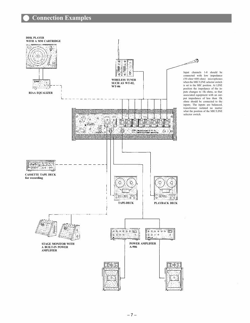
Input channels 1-8 should beconnected with low impedance(50-ohm~600-ohm) microphoneswhen the MIC/LINE selector switchis set to the MIC position. At LINEposition the impedance of the in-puts changes to 1lk ohms, so thatassociated equipment with an out-put impedance of less than 1lkohms should be connected to theinputs. The inputs are balanced,transformer isolated no matterwhat the position of the MIC/LINEselector switch.
CASSETTE TAPE DECKfor recording
TAPE-DECK PLAYBACK DECK
STAGE MONITOR WITHA BUILT-IN POWERAMPLIFIER
POWER AMPLIFIERA-906
– 7 –
Connection Examples

RX-31C BLOCK DIAGRAM
LEVEL DIAGRAM
– 8 –
Block and Level Diagrams

AC ground is provided to the RX-31C and all associated equipment, and this cansometimes causes an increase in hum noise. This is because a ground loop is madethrough the shields of the connection cable and the AC line as shown Fig. 1.
Fig. 1
To solve this problem, either the chassis ground of the signal line should bedisconnected at either piece of equipment, or disconnect the chassis earthground, so that the ground loop is eliminated. However, it is highly dangerous todisconnect the AC ground, as microphones and other equipment connected to themixing console are often touched directly by hand. This may cause an electricshock, in the case of electricity leakage, if any other connected equipment istouched. Therefore the chassis ground line should be disconnected. Whether ornot to disconnect the chassis ground line of other equipment depends on variousconditions. Therefore, this should be checked and determined for each installa-tion. Care must be taken that when the RX-31C is mounted in a metal cabinet, thechassis ground line of other equipment is connected through the cabinet.
– 9 –
Avoiding Ground Loops
Before connecting other equipment to the mixing console, check the impedancesand levels of both. If the impedances and levels do not match, mixing will be verydifficult and the S/N ratio will also be adversely affected.
Each input channel of the RX-31C is provided with a TRIM control. Thoroughunderstanding of the function of a TRIM control will make mixing easily.
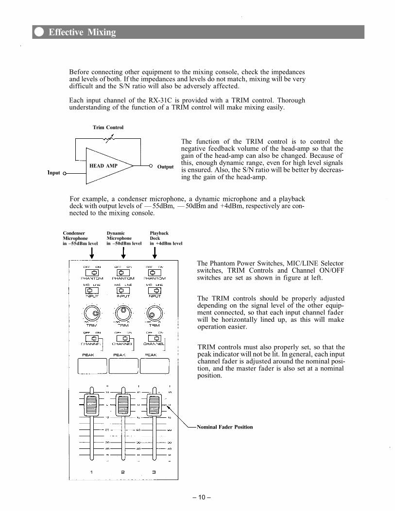
Trim Control
InputOutputHEAD AMP
The function of the TRIM control is to control thenegative feedback volume of the head-amp so that thegain of the head-amp can also be changed. Because ofthis, enough dynamic range, even for high level signalsis ensured. Also, the S/N ratio will be better by decreas-ing the gain of the head-amp.
For example, a condenser microphone, a dynamic microphone and a playbackdeck with output levels of — 55dBm, — 50dBm and +4dBm, respectively are con-nected to the mixing console.
CondenserMicrophonein –55dBm level
DynamicMicrophonein –50dBm level
PlaybackDeckin +4dBm level
The Phantom Power Switches, MIC/LINE Selectorswitches, TRIM Controls and Channel ON/OFFswitches are set as shown in figure at left.
The TRIM controls should be properly adjusteddepending on the signal level of the other equip-ment connected, so that each input channel faderwill be horizontally lined up, as this will makeoperation easier.
TRIM controls must also properly set, so that thepeak indicator will not be lit. In general, each inputchannel fader is adjusted around the nominal posi-tion, and the master fader is also set at a nominalposition.
Nominal Fader Position
– 10 –
Effective Mixing

Frequency Response: +0dB, -3dB. 15Hz~ 30kHz (Measurement of B&K Type 2010 output imp. 5Total Harmonic Distortion:
0.1%, +4dBm at 1kHzHam and Noise (Rg = 150 ohms):
—130dBm Equivalent Input Noise (20Hz~ 20kHz)—132dBm Equivalent Input Noise (IHF A Weighted)—88dBm ALL FADERS DOWN (IHF A Weighted)—73dBm PGM FADER AT NOMINAL AND ALL INPUT FADERS DOWN
(IHF A Weighted)—63dBm (67dB S/N) PGM FADER AND ONE INPUT FADER AT NOMINAL
(IHF A Weighted)Maximum Voltage Gain (Input Trim at "0" position):
PROGRAM 88dB: INPUT to PGM OUTLINE 88dB: INPUT to LINE OUTREC OUT 74dB: INPUT to REC OUTAUX IN 44dB: AUX IN to PGM OUT
Equalization: 63Hz ± l0dB Peaking 250Hz ± l0dB Peaking 1kHz ± l0dB Peaking2kHz ± l0dB Peaking 8kHz ± l0dB Peaking
High Pass Filter: —6 dB/OCT roll-off below 50Hz at —3dB pointsLow Pass Filter: —6 dB/OCT roll-off above 15kHz at —3dB pointsPeak Indicators: Red LED on each input channel
LED's turn on at l0dB below clippingChannel ON/OFF Indicators:
Green LED on each input channelPhantom Power: Phantom powering (48V DC) switch on each input channelDimension: 17.99(W) X 15.65(D) X 6.22(H) inch 457(W) X 397.5(D) X 158(H)mm
INPUT SPECIFICATIONS
CONNEC-TION
INPUT(1-8)
AUX
INPUTSELECTOR
MIC
LINE
ACTUAL LOADIMPEDANCE
FOR USE WITHNOMINAL
50 TOMICROPHONESOR LINES
OR LOWERIMP. LINES
OR LOWERIMP. LINES
TRIMPOSITION
0
—30
0—30
SENSITIVITY(AT MAX GAIN)
—84dBm (0.049mV)
—54dBm (1.55mV)
—44dBm (4.9mV)—14dBm (155mV)
—40dBm (7.75mV)
INPUT LEVEL
NOMINAL
—64dBm (0.49mV)
—34dBm (15.5mV)
—24dBm (49mV)+ 6dBm (1.55V)
—20dBm (77.5mV)
*MAX. BEFORECLIP
—35dBm (13.8mV)
—5dBm (436mV)
+ 5dBm (1.38V)+ 36dBm (48.9V)
+ 9dBm (2.18V)
CONNECTOR
XLR TYPE
XLR-3-31
PHONE JACK
CONNECTION
PROGRAM OUTLINE OUTREC OUT(HEAD) PHONES
FOR USE WITH NOMINAL
OR HIGHER IMP. LINES
OR HIGHER IMP. LINESOR HIGHER IMP. LINES
OUTPUT LEVELNOMINAL
+ 4dBm (1.23V)+ 4dBm (1.23V)—10dBm (245mV)—10dBm (245mV)
MAX. BEFORE CLIP+ 25dBm (13.8V)+ 25dBm (13.8V)+ 10dBm (2.45V)—5dBm (436mV)
CONNECTOR
XLR TYPEXLR-3-32
PHONE JACKPHONE JACK
*0dBm is referenced to 0.775VRMS*Sensitivity is the lowest level that will produce an output of +4dBm (1.23V), or the nominal input level when the unitis set to maximum gain.
*All XLR type connectors are floating ("balanced") and transformer-isolated. Phone jacks are unbalanced (excepthead phone jack, wird Tip = Hot, Ring = Hot, Sleeve = Common)
OUTPUT SPECIFICATIONS
– 11 –
Specifications
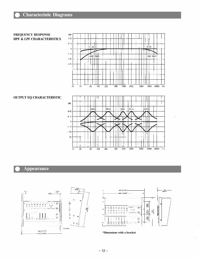
FREQUENCY RESPONSEHPF & LPF CHARACTERISTICS
OUTPUT EQ CHARACTERISTIC
*Dimensions with a bracket
– 12 –
Characteristic Diagrams
Appearance

TOA ELECTRIC CO., LTD.KOBE, JAPAN
Printed in Japan133-02-489-??