operating instruction oi/vm3d-en rev c vm3d 3d … instruction oi/vm3d-en rev c vm3d 3d volumetric...
TRANSCRIPT

Operating Instruction OI/VM3D-EN Rev C
VM3D3D Volumetric Laser Scanner System
Measurement made easy
Automatic stockpile inventory management with 3D volumetric laser scanner Level Products
Automated stockpile management The 3D volumetric scanner system measures the volume of material stockpiles stored out in the open or in large structures like warehouses, silos, bunkers, domes and sheds. By integrating accurate laser technology into a network of scanning instruments, complex surfaces can be mapped accurately. The system makes use of remote monitoring and data processing services to guarantee data integrity to the level needed for confident stock management and precise auditing.
System attributes – Maintenance free, non-contact laser scanner – No calibration required – Regular scheduled surface mapping for granular
solid material stockpiles – Auto-ranging to measure points from 0.5 m to 93 m (1.64
ft to 305 ft) – Scanning motion covers a complete hemisphere – Heated optics prevent condensation issues – Rugged and robust powder coated aluminum
enclosure of the scanner can be used in any environment
A convenient solution – No calibration or maintenance required
(permanently sealed and lubricated bearings) – CSA, ATEX and IECEx potentially explosive
atmosphere ratings – Easy to install and configure without filling
or emptying the vessel
High performance – Performs a complete high-resolution scan in under 45
minutes – Less than 0.3° beam divergence for precision targeting – Collects thousands of points per scan – Artifact removal provides dependable inventory information – Can penetrate moderate dust
Many different materials – Measures all clearly visible surfaces irrespective
of texture, granularity, slope and / or color – Accurately measures to the surface of mineral ores,
grains, and synthetic materials – Examples include: gold and metal ores, sugar, fertilizers,
coal, corn, rice, coffee and plastic pellets
Many different structures – Works in all types of storage buildings including ware-
houses, silos, tanks, bunkers, sheds and domes – Can provide volume estimation for open air stockpiles – Provides volume estimates with less than 2 % error for
volumes greater than 100 m3 (3531 ft3)

2 OI/VM3D-EN Rev. C | Operating Instruction
1.0 About This Manual ................................................................................................................................................... 31.1 Purpose of Document .................................................................................................................................... 31.2 Definition of Symbols ..................................................................................................................................... 31.3 System and Component Names ..................................................................................................................... 3
2.0 Introduction ............................................................................................................................................................. 4
3.0 Site Preparation ....................................................................................................................................................... 53.1 Site Considerations........................................................................................................................................ 5
4.0 Safety ..................................................................................................................................................................... 64.1 Warnings, Cautions and Notices ..................................................................................................................... 64.2 Certification .................................................................................................................................................. 64.3 Handling ....................................................................................................................................................... 64.4 Power Connections ....................................................................................................................................... 64.6 ESD Warning ................................................................................................................................................. 64.7 Electrical Warnings ........................................................................................................................................ 64.8 Environmental Information ............................................................................................................................. 74.9 Laser Safety ................................................................................................................................................ 74.10 Labels and Label Placement ......................................................................................................................... 8
5.0 Installation ............................................................................................................................................................. 105.1 General information ..................................................................................................................................... 115.2 Unpacking ................................................................................................................................................... 115.3 Handling ..................................................................................................................................................... 115.4 Environmental Conditions ............................................................................................................................. 115.5 Alignment .................................................................................................................................................... 115.6 ESD (Electro Static Discharge) and Lightning Strike /Event ............................................................................ 115.7 Earthing ...................................................................................................................................................... 115.8 Cables and connections ............................................................................................................................... 125.9 Special Conditions of Safe Use .................................................................................................................... 125.10 VM3D Scanner Dimensions ........................................................................................................................ 125.11 VM3D Scanner Installation ......................................................................................................................... 135.12 Electrical Connections of the VM3D Scanner ............................................................................................. 135.13 Mounting plate .......................................................................................................................................... 145.14 VM3D Control Box Installation .................................................................................................................... 15
5.14.1 VM3D Control Box - Steel for general purpose .................................................................................... 155.14.2 VM3D Control Box - Painted Steel or Stainless Steel for hazardous area (dust ignition protection) ......... 16
5.15 Wiring inside the VM3D Control Box ........................................................................................................... 185.16 Fuses ........................................................................................................................................................ 205.17 Antenna Installation ................................................................................................................................... 20
6.0 Operation .............................................................................................................................................................. 22
7.0 Technical Specifications ......................................................................................................................................... 23
8.0 Maintenance, Service & Repair ............................................................................................................................... 248.1 Fuse replacement ........................................................................................................................................ 248.2 Cleaning ...................................................................................................................................................... 248.3 Repacking ................................................................................................................................................... 24
9.0 Volume estimation using ABB data center ............................................................................................................... 25
Appendix A: Certifications ............................................................................................................................................ 27
TABLE OF CONTENTS

Operating Instruction | OI/VM3D-EN Rev. C 3
1.0 About This Manual1.1 Purpose of DocumentThis document is intended for personnel installing, maintaining and using the VM3D Volumetric scanning system. It contains instructions for installation, operation and troubleshooting.
Please read this manual carefully before attempting to install or operate this product. To ensure personal safety and opti-mal performance, make sure you thoroughly understand the contents of this manual before installing, using or performing maintenance on any part of the VM3D system.
All servicing of the equipment is to be performed by Qualified Service Personnel only. There are field serviceable parts in the VM3D control box but not in the VM3D scanner. Any maintenance or repair work on the VM3D scanner must be carried out at the factory
No user/operator adjustments inside the VM3D Volumetric Laser Scanner System are necessary or recommended by the manufacturer.
Service of control box can be done in the field.
1.2 Definition of Symbols
This publication includes Warning, Caution, and Information symbols where appropriate to point out safety-related as well as other important information. It also includes the Tip symbol to point out useful hints to the reader. The corresponding sym-bols should be interpreted as follows:
The laser warning symbol indicates the presence of a potential hazard related to the presence of a laser.
The electrical warning symbol indicates the pres-ence of a potential hazard which could result in electrical shock.
The ISO General Warning symbol indicates safety information that must be followed by the user. The information concerns the presence of a potential hazard which could or may result in personal injury or even death.
The information symbol alerts the reader to pertinent facts and conditions in the use of the equipment.
The tip symbol indicates advice on, for example, how to use a certain function.
The ESD symbol indicates the presence of equip-ment sensitive to electrostatic discharge.
The Ground symbols is used to identify protective earth conductor terminals.
1.3 System and Component Names
This publication describes different components of the VM3D Volumetric Laser Scanner System, i.e.: VM3D Scanner VM3D Control Box

4 VM3D Volumetric Scanner System | User Manual
2.0 Introduction
The VM3D Volumetric Laser Scanner is a laser scanner for measuring the volume of material in a warehouse or on a stock pile. The scanning capability produces accurate mea-surements of rough surfaces with a complex profile and the output gives a true representation of the volume of material.
The VM3D Scanners are unlike single point level transmitters; they take into account the shape of the surface, accurately calculating the effects of “cone-up”, “cone-down” or irregu-larities on the material volume. Whilst a single point mea-surement can produce errors in excess of 30% on the true volume, the VM3D Scanner uses thousands of data points to improve the volumetric accuracy to better than two percent in most applications. The VM3D Volumetric Laser Scanner Sys-tem is a complete process and stock control tool in a single system.• Measures the volume of material in warehouses and on
stock piles• Rugged and robust housing• Built-in dust protection • Built-in fog protection
The VM3D System is composed of a VM3D control box and the VM3D scanner(s). One VM3D control box can supply up to 4 VM3D scanners and transmits the raw data from the VM3D Scanner(s) to the ABB data center over the 3G cellular service.The VM3D scanner makes use of non-contact laser techno-logy to map the surface profile of a stockpile thus allowing the volume of material to be determined. The dimensions of ware-houses, bunkers and walled vessels are stored at the data center. The difference between the measured volume and the empty volume gives the material volume in cubic meters. The VM3D Scanner is mounted above the material to be mea-sured. It is aimed vertically downwards and must be mounted high enough so that the entire surface can be scanned other-wise more than one VM3D Scanner is required.
Scanner
Controller
3G signal
Volume calculation <20 min.
Volume, mass & 3D image via secure server

User Manual | VM3D Volumetric Scanner System 5
3.1 Site ConsiderationsThe installation has to be planned ahead and safety protocols and working instructions of the plant need to be considered.
Safety protocolsEach plant has regulations and procedures that need to be identified and adhered to especially with regards to docu-mentation, welding guidelines, special regulations concerning small spaces, working at heights and what equipment is al-lowed to be brought in the plant. The inductions of all person-nel involved with the installation have to be prepared.
Cable routesPower and Ethernet cables need to be installed for the VM3D Scanner to operate. The VM3D control box should be installed in a convenient location for servicing taking into account the star topology of the system and the 100 m (328 ft) limit on the length of the cables going to the VM3D scanners. The VM3D control box requires a dedicated electrical circuit coming from the plant’s electrical distribution panel. In general the sim-pler the cable installation-routing is, the better but the cable routing depends on many factors. Those factors are, but are not limited to, local routing standards, site configuration, risk due to vehicle traffic, obstructions to be avoided and the 100 m (328 ft) limit on cable lengths. It is important to keep the cables out of possible harm’s way.
The Ethernet cables must be pulled through the cable glands on the VM3D scanner side and on the VM3D control box side before the RJ45 connectors are crimped on the cables. The RJ45 connec-tors will not fit though the cable glands.
MountingThe ABB VM3D Control Box is delivered with brackets for wall mounting. The VM3D scanner is designed to be mounted vertically on a flange above the stock pile of material to be measured. Prior to installation it is necessary to determine where the mounting brackets for the flanges will be mounted and how they will be attached to the existing structure.The design of the VM3D scanner mounting flanges should be based on the diagram shown on page 14.
VM3D Scanner positionsThe VM3D scanners should be mounted for optimal viewing; e.g. the smallest number of scanners to get complete cover-age are installed bearing in mind that the furthest distance
that can be measured from the VM3D scanner head is 93 m (305 ft). The VM3D scans a pattern of concentric circles over a hemisphere. The VM3D scanner must be installed high enough to get a good angle of scan with respect to the mate-rial stockpile. It must be able to move freely over 360° and should not be installed below material feeders or anyplace where there is a likelihood of the scanner being struck by or buried in material. In some cases beam placement inside structures can be a problem. When multiple VM3D scanners are to be installed for a single stockpile they must be positioned for maximum coverage while ensuring that there is still some overlap. The environ-ment should be evaluated in terms of dust and fog thickness and variations. Thick dust and or fog will limit the distance that the scanner can measure and reduce the accuracy of the overall volume determination. There are often times when dust is at a minimum, typically between loading cycles. These times need to be determined and used to decide on the best times to perform stockpile scans.
VM3D Control Box mountingThe maximum cable distance between VM3D Control Box and VM3D scanners is 100 m. The VM3D Control Box must be powered by an dedicated circuit from the plant’s distribu-tion panel, able to supply up to 500 VA. ABB suggests AWG 14 electrical wires between the distribution panel and the VM3D Control Box. The circuit must be protected by a suit-able primary branch circuit breaker and comply with the local electrical code.
Data HandlingThe raw data measured by the VM3D scanners is encrypted and sent over the 3G cellular network to the ABB data center for compilation and analysis. This requires appropriate 3G or GPRS (2G) cellular coverage. In many cases this can be achieved by mounting the antenna and cable supplied by ABB on the VM3D control box. Low signal strength at the position of the control box will require the antenna to be installed at an alternate location that is as high as possible, away from heavy metal structures and possibly outdoors. In some cases it may also require the use of a special antenna; for example a direc-tional antenna pointing to the closest cell phone tower.If 3G coverage is not available the data can also be send us-ing a customer supplied internet connection. Please contact ABB to discuss special antenna installations or customer supplied internet connections, refer to back cover for contact information.
3.0 Site Preparation
Volume, mass & 3D image via secure server

6 OI/VM3D-EN Rev. C | Operating Instruction
4.0 Safety
4.1 Warnings, Cautions and NoticesUser must comply with all warnings, cautions and notices indicated in this manual. Failure to comply with any of the warnings, cautions or notices can result in personal injuries and/or equipment damages. If you do not fully understand the information contained in this manual, please contact ABB. Refer to the back cover of this manual.
4.2 Certification ABB instruments conforms to the following requirements:
CE Quality Standard: ISO9001:2008
Electromagnetic compatibility directive 2004/108/EC
Low voltage directive 2006/95/EC
CE marking directive 93/68/EEC
Radio and telecommunications terminal
equipment1999/5/EC*
ATEX directive 94/9/EC (Europe)
Refer to SM/LM80-EN Safety Report for ATEX.
Hazardous Locations Safety; Canadian Standards
Association (for Canada and the US)
Potential explosive atmospheres (global access)
TUV, Electrical Safety
Electrical safety
CAN/CSA C22.2 No. 61010-1:2004
UL 61010-1:2004
EN 61010-1:2004
C1: This product has been tested to the requirements of
CAN/CSA-C22.2 No. 61010-1, second edition, including
Amendment 1, or a later version of the same standard
incorporating the same level of testing requirements.
*WarningThis is a class A (industrial) product. In a domestic environment this product may cause radio interference in which case the user may be required to take adequate measures.
4.3 HandlingThe VM3D Control Box and the VM3D scanner weigh 12 kg each. ABB recommends the use of a lift or the help of another person to lift the VM3D Control Box and the VM3D Scanners. Make sure to use proper body mechanics (bend your knees) when lifting the VM3D Control Box or the VM3D scanners to avoid personal injuries.
4.4 Power ConnectionsIn accordance with international safety standards, the VM3D control box uses a three wire power cord connected directly to the plant electrical panel that provides grounding for the chassis of the control box and up to four VM3D scanners.
4.5 General Warnings
Failing to comply with any of the instructions, precautions or warnings contained in this manual is in direct violation of the standards of design, manufacture, and intended use of the equipment.ABB assumes no liability for the user’s failure to comply with any of these safety requirements
Do not, under any circumstances, remove the warning and caution labels. Information must be available at all times for the security of the user. Do not operate the equipment in an area if there is a risk of flammable gases.Read this manual thoroughly before using this equipment.Do not use the equipment if you do not under-stand the content of this manual or if the equip-ment shows any sign of damage. Please contact ABB customer service. Refer to the back cover of this manual for contact information.If the equipment is used in a manner not speci-fied by the manufacturer, the protection provid-ed by the equipment may be impaired. Equipment intended for field installation by qualified service personnel according to manu-facturer’s installation instructions and local/na-tional wiring requirements.
4.6 ESD Warning
Electrostatic Sensitive Components Any maintenance procedures inside the VM3D scanner terminal block or inside the VM3D control box should be performed using appro-priate ESD precautions. If you are not familiar with ESD protection, contact ABB customer support. Refer to the back cover of this manual for contact information.
4.7 Electrical Warnings
High VoltageDisconnect power at circuit breaker of the plant’s distribution panel before opening VM3D Control Box. Ensure that the equipment and any devices or power cords connected to the VM3D Volu-metric Laser Scanner System are properly grounded. Protective earthing connection (grounding) must be active at all times.The absence of grounding can lead to a po-tential shock hazard that could result in serious personnel injury. If an interruption of the protec-tive earthing is suspected cut the power to the VM3D system at the plant’s distribution panel and have the electrical circuit tested.

Operating Instruction | OI/VM3D-EN Rev. C 7
4.8 Environmental Information
The VM3D Volumetric Laser Scanner System has required the extraction and use of natural resources for its produc-tion. Therefore, the VM3D Volumetric Laser Scanner System may contain hazardous substances that could impact health and environment. In order to avoid dissemination of these hazardous products into the environment and also to reduce the extraction and protect our natural resources, ABB inc. strongly recommends to use appropriate recycling systems in order to make sure materials used to produce your equipment are reused or recycled in a sound way. At the end of life of the system, contact your distributor before disposing of your equipment.
The VM3D Volumetric Laser Scanner System is not subject to the European WEEE directive based on the exemption for fixed industrial installations. However, most of its components are easily recyclable. The VM3D system falls into this cat-egory by virtue of the fact that it is meant to be permanently installed by a qualified installer in industrial warehouses in locations like petrochemical complexes, ore processing sites and food processing sites in order to measure the volume of stockpiles kept inside the warehouses. The VM3D system is not meant to be moved from site to site and serves no useful stand-alone purpose.
4.9 Laser Safety The VM3D scanner uses a near infrared laser for distance measurements. The VM3D scanner is classified as a class 1M laser device according to IEC60825-1, Ed 1.2, 2001-08. Class 1M devices are considered eye safe and cannot lead to eye injury unless an optical instrument that focuses down the energy is used.
• Wavelength 905 nm• Peak power 24 W• Average Power 12 mW• Pulse Duration 20 ns• Pulse rep frequency 25 khz• Pulse energy 50 nJ• Beam diameter 20 mm• DivergenceΔ<0.3°
Class 1M laser product according to IEC60825-1, Ed 1.2, 2001-08 during all procedures of operation:Laser radiation, do not view directly with optical instruments (binoculars, tele-scopes, magnifying lenses)

8 OI/VM3D-EN Rev. C | Operating Instruction
Figure 4-2 VM3D Scanner Laser warning, located on bottom part of scanner near aperture
Figure 4-4 Location of VM3D Scanner Labels
Figure 4-3 Company Logo
4.10 Labels and Label Placement
Figure 4-1 VM3D Scanner Name Plate, located on top part of scanner

Operating Instruction | OI/VM3D-EN Rev. C 9
Figure 4-6 VM3D Control Box-EX Name Plate, located on the front cover of the control box, refer to Figure 5-5
Figure 4-5 VM3D Control Box-General Purpose Name Plate, located on the front cover of the control box, refer to Figure 5-5

10 OI/VM3D-EN Rev. C | Operating Instruction
5.0 Installation
Installation of the VM3D system consist of • installing the control box typically on a wall• wiring inside the control box • connecting power to the control box• installing the VM3D scanners at their predetermined locations• connecting cables (power and Ethernet) between the VM3D scanners and control box• connecting the antenna
These steps are described in detail in following sections. Prior to installation, the locations of the control box and the scanners need to be determined taking into consideration the 100 m (328 ft) cable limit.
Figure 4-7 VM3D Topology
VM3D Control Box
VM3D Scanner#4 (optional)
Antenna
3G
VM3D Scanner#3 (optional)
VM3D Scanner#2 (optional)
VM3D Scanner#1
C2 C3
C2 C3
C2 C3
C2 C3C2
C3
VM3D3D Volumetric Laser Scanner System
C1
C1
C4
C4
115/230 VAC
Power cable, 115/230 VAC, 3 conductors, 14 AWG
Catagory 5e Ethernet Cable, strandedshielded, 24 AWG, ≤ 100 m
Power cable, 24 Vdc, 3 conductors, shielded, 16 AWG, ≤ 100 m
RF cable, LMR400, N-type connectors

Operating Instruction | OI/VM3D-EN Rev. C 11
5.1 General informationThe VM3D Volumetric Laser Scanner System is an optical, line of sight device that is used for non-contact volume measure-ment. The scanner should be placed to minimize obstacles between it and the stockpile being monitored.
5.2 UnpackingThe VM3D Volumetric Laser Scanner System, composed of the VM3D control box and one or more VM3D scanner(s), is supplied in cardboard containers with internal shock absorb-ing packaging. Always transport the VM3D system in the packaging supplied to reduce the chance of damage.
5.3 HandlingThe product is designed to withstand many industrial environ-mental conditions. However, a few handling precautions will ensure reliable operation of the unit for many years to come:• DO NOT DROP THE VM3D SCANNER or VM3D Control
Box.• Do not open when an explosive dust atmosphere is pres-
ent.• Remove dirt or dust from glass lenses of the VM3D scan-
ner with a clean, damp cloth. Avoid oily rags. • Always turn off power at the electrical panel before before
doing any installation or maintenance.• Use a 12 x 12 x 300 mild steel bar to open and close the
VM3D scanner’s wiring compartment.• Care must be taken to keep the seal of the VM3D scan-
ner clean and lightly lubricated with Vaseline®.• Do not expose the inside of the VM3D control box or of
the VM3D scanner to any liquids or dirt.• Ensure that the cable glands are tight after connecting
the external cables.• Ensure that the lid of the terminal compartment is tight
after connections have been made.• Do not point the VM3D scanner at the sun.• Store in a cool dry place. • Do not apply force to moving parts.• Do not look directly at the VM3D scanner with optical
instruments such as binoculars or a telescope.• The use of an anti-static wrist strap is recommended
when VM3D Control Box cover or VM3D Scanner com-partment are open.
5.4 Environmental ConditionsThe VM3D Laser Scanner System should be installed in an area that complies with the specified specifications, refer to 7.0 Technical Specifications. Direct exposure to the sun may require a sun shield for the VM3D scanner as well as for the VM3D control box to prevent overheating. When installed, the VM3D scanner should be accessible for commissioning, programming and troubleshooting if necessary.
While the initial (cold start) accuracy of the VM3D Scanner is likely to be within specifi-cation, a settling period of approximately 15 minutes may be required to allow the elec-tronic components to fully warm up and the internal temperature to stabilize.
5.5 AlignmentThe VM3D scanner is simple to install and align. The VM3D scanner requires a clear line of sight to the stock pile to be measured and should be mounted vertically.
5.6 ESD (Electro Static Discharge) and Lightning Strike /EventThe VM3D laser scanner system uses electronic components that can be damaged by lightning strikes or static electricity present in most work environments. In order to protect the VM3D system components from such hazards, make sure it is connected to a good ground earth, that all electrical connec-tions are tight, that appropriate surge protection circuits are installed and that lightning rods are used if the equipment is to be mounted at high exterior locations.
5.7 EarthingThe ground conductor from the distribution panel to the VM3D control box is used as the main ground of the VM3D system. The external side-screw is for local grounding, to be wired to a grounded structure.

12 OI/VM3D-EN Rev. C | Operating Instruction
5.8 Cables and connectionsUse only braided shielded cables (AWG16 or 1.5 mm2 multi-core cables recommended) that are rated for exposure to direct sunlight and chemicals potentially present in the stock-pile area for power distribution and Ethernet. The use of cable conduits is recommended to reduce risks of mechanical or chemical damage to cables.Care should be taken when laying out cables to respect the maximum bending radius and avoid high voltage electrical circuits.
5.9 Special Conditions of Safe Use• Do not open the terminal compartment when an explosive
dust atmosphere is present.• Appropriate insulated lugs or ferrules shall be used for
connections to the terminal blocks and screws.• Use only the cable glands supplied with the system.
Figure 5-1 VM3D Scanner Dimensions
R250 mm [9.84 in]
190 mm [7.48 in]
129 mm [5.08 in]
467 mm [18.40 in]
288 mm [11.32 in]
127 mm [5.00 in]
160 mm [6.30 in]
DATUM
DO NOT OBSTRUCTLASER HEADSCANNING ZONE
4X M12 X 1.75 GRADE 8.8See installation instructions for fastener selection and assembly torques
5.10 VM3D Scanner Dimensions

Operating Instruction | OI/VM3D-EN Rev. C 13
5.11 VM3D Scanner InstallationThe VM3D Scanner should be installed above a stock pile, the laser head pointing downwards towards the surface of the material to be measured. If the VM3D Scanner is installed out-side, a sun screen should be in place to protect it from direct sunlight which can cause it to overheat. The VM3D Scanner must be mounted at a location with mini-mal wind or vibrations and high enough so that a clear and constant view of the surface is obtainable. This is particularly important when the warehouse or silo is full otherwise “shad-ows” can occur during the scanning process which will lead to an overestimation of the material volume.It is recommended that the VM3D Scanner be installed with a metallic mounting flange, based on the diagram on page 13. This flange should be relatively flat. The system’s accuracy is impacted by the anchor stiffness. No visible jitter due to anchor weakness should be perceptible in normal operation.The mounting surface should be relatively flat (surface flat-ness better than 0.25 mm (0.01 in) recommended) and free from debris prior to installation. Four (4) M12 x 1.75mm pitch fasteners grade 8.8 or SAE fasteners 1/2-13 grade 5 or higher are to be used with either a threaded flange or nylon locking
nuts.In order to avoid galvanic corrosion issues and preserve as-sembly integrity, galvanized fasteners, nuts and washers are preferred to stainless steel hardware. If the mounting flange includes threads, the threads shall be dimensioned according to the fastener grade to preserve assembly integrity at installation and over time. Always use washers under fasteners heads and nuts. Use zinc plated DIN 125 or SAE standard washers.The length of the fasteners shall be determined based on the thickness of the mounting interface in order to have at least two full threads protruding over the nylon locking element of the nuts. Assembly torque for typical M12 x 1.75mm pitch grade 8.8 fasteners is 85 N*m. Use the same value for SAE 1/2-13 grade 5 fastenersLocal regulations shall be followed with regards to environ-mental loads such as seismic loads, ice, wind, etc. Proof testing the mounting bracket considering maximum recom-mended environmental loads is imperative to guarantee safe installation.
Figure 5-2 Electrical and wiring connections
Power Indicator
Ethernet port
Scanning indicator
24V DC Earth
Ext
Com Sig
Use only the circled connections
Ext Com
Ext Sig Reset IP Address
Ethernet cable
+
-
Ground
5.12 Electrical Connections of the VM3D Scanner

14 OI/VM3D-EN Rev. C | Operating Instruction
5.13 Mounting plateABB does not supply standard mounting hardware for the VM3D as each installation is different. However, mounting brackets should be based on the following suggested mounting plate design.The VM3D control box comes with hardware for standard wall mounting.
Ø 133 mm (5.25 in) Ø 160 mm (6.3 in)
220 mm(8.7 in)
280 mm (11 in)
7X Ø 16.5 mm(.65 in)
80 mm (3.15 in)
80 mm (3.15 in)
25 mm (1 in)
170 mm (6.7 in)
Use at least 6.35 mm (0.25 in) thick steel plate

Operating Instruction | OI/VM3D-EN Rev. C 15
5.14 VM3D Control Box Installation
The VM3D box is available in three versions; i.e. one standard version for use in a safe environment and two versions for use in a hazardous area. Of the latter, one model is painted steel and one model is stainless steel for corrosive environments.The VM3D control box is delivered fully assembled. Open the cardboard box and take out the VM3D control box. The procedure with detailed instructions on how to install the VM3D control box on the wall are inside the control box. Refer to picture 5-4 and 5-5 for dimensions. Use a sun shield to avoid exposing the control box to direct sunlight if it is mounted outside.
The VM3D Control Box weighs 12 kg. ABB recommends the use of a lift or the help of another person to lift the VM3D Control Box. Make sure to use proper body mechanics (bend your knees) when lifting the VM3D Control Box to avoid personal injuries.The VM3D control box must be connected to a circuit breaker on a dedicated circuit in the plant’s electrical distribution panel. The circuit breaker must be within easy reach of the operator and clearly marked as the power disconnecting device for the VM3D system.
Figure 5-3 Dimensions of VM3D Control Box - Mild steel General purpose
508 mm [20 in]
304 mm [12 in] 224 mm [8.81 in]
5.14.1 VM3D Control Box - Mild Steel for general purpose
470 mm [18.50 in]
344 mm [13.56 in]
4x 10 mm [0.41 in]
Figure 5-4 VM3D Control Box Dimensions for installation

16 OI/VM3D-EN Rev. C | Operating Instruction
388 mm (15.28 in)
500
mm
(19
.69
in)
2x 13 mm(.50 in)
2x 8 mm(.31 in)
2x 8 mm(.50 in)
350 mm (13.78 in)
399
mm
(15
.62
in)
2 mm(.1 in)
205 mm (8.07 in)
143 mm (7.45 in)
BODYGROUNDSTUD
25 mm(1 in)
149 mm(5.85 in)
44 mm(1.75 in)
401
mm
(15
.81
in)
Figure 5-5 Control box - Painted Steel or Stainless Steel for hazardous area (dimensions are the same)
5.14.2 VM3D Control Box - Painted Steel or Stainless Steel for hazardous area (dust ignition protection)
38 mm(1.50 in)
232 mm(9.13 in)
3.4-3.9 Nm(30-35 in-lbs)
For grounding at least one fastener on each gland plate must not have a nylon washer under the head.
The VM3D Control Box version for hazardous areas (either painted steel or stainless steel) has to be properly grounded. To assure the proper grounding, one nylon washer was removed form its fastener of each gland plate at factory. Refer to below picture for details.Refer to above drawing for torque details.
Figure 5-6 Control box - Front View; nylon washer removed as indi-cated
Figure 5-7 Control box - Side View; nylon washer removed as indica-ted
Figure 5-8 Control box - Back View; nylon washer removed as indica-ted

Operating Instruction | OI/VM3D-EN Rev. C 17
Figure 5-9 VM3D Control Box Connectors
Main input power
Ethernet connectors for scanners
Power supply connectors for
scanners
Antenna Cable and connector
Once the VM3D control box is installed on the wall, the antenna and wiring have to be connected, i.e. Ethernet and power cables from the VM3D scanners to the VM3D control box and mains power to the control box. One VM3D control box can control up to 4 scanners. The VM3D Control box has been designed to be powered as soon as power is turned on at the plant’s circuit breaker.
Prior to opening the door of the VM3D control box or performing any maintenance on the VM3D system, power must be disconnected at the circuit breaker in the plant’s electrical distribution panel. Access to the breaker located in the plant’s distribution panel must not be hindered in any way; do not obstruct the door opening, do not position equipment that obstructs access to the circuit breaker, leave 350 mm (14 in) clearance above the panel.

18 OI/VM3D-EN Rev. C | Operating Instruction
ABB recommends the following cables and connectors:
Ethernet cable Belden 7939A 7939A -40°C with shield, stranded, bonded, OD 0.315in
Ethernet connectors RJ45 shielded connector for AWG 24-26 Stranded wires
Power cable (from control box to scanners) 16 AWG, 105°C or +, 3 conductors shielded
Antenna cable LMR-400 low-loss coaxial cable
5.15 Wiring inside the VM3D Control BoxOnce the VM3D control box is installed and the power and Ethernet cables are laid out in the plant, the cables need to be passed through the cable glands, the Ethernet connec-tors need to crimped on and the electrical connections inside the control box need to be completed. Refer to the wiring diagram for details (Figure 5-10).
Prior to completing the electrical connections inside the VM3D control box, make sure that the power is interrupted at the circuit breaker in the plant’s electrical distribution panel.Wiring inside the VM3D control box needs to be done by qualified personnel only. The length of power input AC wires inside the VM3D Control Box enclosure shall be at least 150 mm (6 inches) long. Some strain relief needs to be applied on all wires during installation.Wire identification shall meet the requirements of the local/national electrical code.The layout inside the VM3D control box must not be altered. The input ground conductor must be connected to the plate at the designated areas as identified in the wiring diagram.
The VM3D Control box uses CE and ATEX certified cable glands. The VM3D control box itself is delivered with cable glands for power and Ethernet. Each VM3D scanner is deliv-ered with 4 1/2” NPT cable glands. Two cable glands are used to connect power and Ethernet to the VM3D scanner and two for connection to the control box. At delivery all cable gland entries are protected. When installing them, make sure to fold the cable shield over the O-ring which presses the braiding against the inside wall of the body, this ensures good electri-cal contact.
ABB will not assume any responsibility for any cable glands other than the ones supplied with the VM3D system. Cables glands not designed for braided shielded cables or cables glands lacking ATEX and CE certifications should never be used.
ABB recommends the use of metal cable conduits for wiring particularly if some parts of the installation are outside. If metal conduits are not used, ABB recommends the use of surge/lightning protectors. Ignoring these recommendations could result in permanent damage to the VM3D system and may void the warranty. Contact ABB for more information on surge and lightning protection, refer to the back cover of this manual for contact information.
The VM3D control box comes with two surge/lightning protectors for the 3G cellular antenna cable. One of the surge protectors is permanently mounted to the control box, and the other one is meant to be installed at the point where the antenna cable enters the building if the antenna is mounted outside. Properly grounded lightning protection is typically required for any cables entering a building from outside. Refer to the antenna installation section for more details.

Operating Instruction | OI/VM3D-EN Rev. C 19
Figure 5-10 Wiring diagram

20 OI/VM3D-EN Rev. C | Operating Instruction
5.16 FusesThe AC input power is protected by means of a circuit breaker and the output power for the VM3D scanners is protected with fuses, refer to the wiring diagram. Spare fuses are supplied with the VM3D control box; they are located inside the control box in a spare fuse box. Make sure only the correct fuses are used; 2A/250V fast (5x20 mm).
5.17 Antenna Installation
Proper installation of the antenna is an important aspect to the correct function of the VM3D system. Below are instructions on how to safely install the antenna. In addition to the general safety instructions in this manual you must observe all local plant safety procedures and safety laws applicable to your country.
The easiest way to install the antenna is on top of or nearby the VM3D Control Box. Make sure to properly ground the antenna through the VM3D Control Box frame ground.
If the VM3D system does not function with the antenna in this configuration, for example if the building blocks radio transmissions, the antenna will have to be installed at a high point outside the building.The location of the antenna installation should be selected for maximum signal strength.
Most countries require properly grounded surge/lightning protector to be installed when a cable enters a building. Make sure to comply with the national building codes and electrical standards. Note that the cable supplied with the antenna is not weatherproof. For outdoor installation use an appropriate cable, refer to Section 5-14 for cable recommendations.
Do not over torque the screw that fixes the gas discharge tube element in place. Finger-tight only.
If the antenna has to be installed on a structure like a mast or a tower, make sure to build the structure according to the safety standards in your country and to have the antenna installed by qualified personnel.
The antenna supplied by ABB with the VM3D system offers a 360-degree radiation pattern that will function in most medium to high population density areas. If the installation site is very remote and the 3G signal is weak you may require a directional antenna. Contact ABB more information on alternate antennas, see back cover for contact information.
Figure 5-11 Properly grounded surge/lightning protector
Gas discharge tube under screw. Screw finger tight only.

Operating Instruction | OI/VM3D-EN Rev. C 21
Antenna Details
Manufacturer Terra Wave
Manufacturer Part Number M4030030O10006T
Antenna type Omnidirectional
Operating frequency range 824 – 2500 Mhz
Nominal input impedance 50 ohms
Gain 3 dBi
Maximum Power input 100 W
Vertical Beamwidth 50°
Horizontal Beamwidth 360°
Polarization Vertical
VSWR @ 50 ohms <= 1.5
Size 4” x 5” [10.16 cm x 12.7 cm]
Weight 817g
Connector N Jack (female)
Connector placement Bottom
Mount Hardware Inclusive. Yes
Mount Hardware that fits 1.25” – 2” [3.175 cm - 5.08 cm] Mast
Wind 193 km/h
General recommendations for antenna installation: 1. Observe all relevant local and national safety procedures,
regulation and laws applicable to the installation site.2. Antenna installation should be done by qualified
personnel only. 3. Consider safety and performance when selecting the
installation site (away from metals structures like heating and cable ducts...).
4. Plan ahead for the installation; have the necessary machinery to raise the mast or tower on hand, have clear work assignments for all the installation team members, have a supervisor on hand to oversee the installation.
5. The installation should not take place if there is any risk of lightning or strong winds.
6. All the installation team must have appropriate safety gear including but not limited to insulated safety shoes, rubber gloves, high visibility safety vest, safety harness ...
7. During installation do not use a metal ladder. Use a wood or fiberglass ladder instead.
8. If any part of the antenna assembly comes into contact with a power line, make sure all members of the installation team stand back and call the local power utility.
9. Never touch nor let any part of your body touch the antenna when the power is switched on at the VM3D control box circuit breaker in the plant’s distribution panel.
The antenna supplied with the VM3D system comes with a mounting bracket and mounting hardware. The antenna should always be mounted vertically with the cable pointing downward. Weatherproofing must be applied at the connection point from the antenna to the antenna cable.
ABB recommends that the antenna be grounded, country regulations regarding antenna grounding must always be observed.
The cable should be kept as short as possible because cable length also determines the amount of signal loss (the longer the run, the greater the loss). ABB recommends using a LMR-400 low-loss coaxial cable between the VM3D Control Box and the 3G antenna.
The surge/lightning protector supplied with the VM3D control box must always be used when the antenna is mounted outside. It is designed to protect radio equipment from static electricity and surges of up to 5kA. This will not provide protection against a direct lightning strike, a lightning rod should be installed to avoid this.
The gas discharge tube inside the surge/lightning protector changes from an open circuit to a short circuit almost instantaneously in the presence of voltage and energy surges, providing a path to ground for the energy surge. Even if the gas discharge tube has a multi-strike capability, the gas discharge tube should be replaced after an event. ABB supplies one spare gas discharge tube located in the VM3D Control Box with the fuses.
Two lightning protectors are supplied with the VM3D Control Box. One is permanently connected to the enclosure, the other is supplied as a front-end discharge unit, intended to be installed just before entering the building. The supplied lightning protector specifications are given in the table below.

22 OI/VM3D-EN Rev. C | Operating Instruction
Manufacturer L-com
Manufacturer part number for Lightning arrester AL-NMNFB-9
Manufacturer part number for Replaceable 90V gas dsicharge tube LPX090
Frequency Range 0 - 3 GHz
Connectors Types N-Male to N-Female Bulkhead
Protector Complies With IEC / IEEE Standard
VSWR 1:1.3 Max
Insertion Loss 0.4 dB Max (0 - 3GHz)
Impedance 50 ohms
Standard Gas Tube Element:
DC Breakdown Voltage Indicated
90 V 20%
Gas Tube Impulse Breakdown Voltage 1000 V 20%
Gas Tube Insulation Resistance 10,000 Mohms
Maximum Withstand Current 5 KA
Power Envelope power 20W
Continuous wave power 10W
6.0 OperationThe VM3D system (VM3D scanner(s) and VM3D control box) is set to operate automatically. Once the system is installed and configured, it does not require user intervention for regular operation. The end-user retrieves the computed volume and data from the ABB website, refer to section 9.0 Volume estimation using ABB data center.

Operating Instruction | OI/VM3D-EN Rev. C 23
7.0TechnicalSpecificationsThe electrical specifications are given in the following tables. All values are nominal.
Measurement
Single point range 0.5 m to 93 m (1.5 ft to 305 ft)
Single point resolution ±10 mm (0.4 in)
Single point accuracy ±30 mm (1.2 in)
Coverage Complete hemisphere scan
Nominal surface coverage 65m (213 ft) radius circle (90° cone, scanner 65 m (213 ft) above stockpile)
Accuracy Less than 2% error on volumes greater than 100 m³ (328 ft³)
Update rate Complete scan in less than 45 minutes
VM3D Scanner per control box maximum 4
Electrical Specifications of VM3D Control Box
Rated input voltage 115/230 VAC
Line voltage fluctuation Not to exceed 10% of the nominal line voltage
Rated frequency 47-63 Hz
Rated power consumption 500 VA
Fuse type (output): 2A/250V fast (5 x 20 mm; 0.2 x 0.79 in)
Output rating: 24 V DC, 1A (4x)
Mechanical Specifications of
VM3D Control Box
General Purpose Hazardous area
(dust ignition protection)
Hazardous area
(dust ignition protection)
Width 304 mm (12 in) 388 mm (15.28 in) 388 mm (15.28 in)
Height 508 mm (20 in) 500 mm (19.69 in) 500 mm (19.69 in)
Depth 224 mm (8.8 in) 205 mm (8.07 in) 205 mm (8.07 in)
Weight (approx.) 16 kg (35 lb) 17.2 kg (38 lb) 17.2 kg (38 lb)
Enclosure Mild steel, left hinged door Painted steel, left hinged door Stainless steel, left hinged door
Mounting Wall mount Wall mount Wall mount
Electrical Specifications of VM3D Scanner
Rated input voltage 24 V DC
Current 1A; 2.2 A in-rush at start-up (< 100 ms)
Mechanical Specifications of VM3D Scanner
Overall dimensions (W x H) 190 x 884 mm (7.48 x 34.8 in)
Weight 12 kg (± 0.5) (26.4 lb)
Environmental Specifications
Scanner operating temperature –32 °C to +60 °C (–89.6 °F to +140 °F); extended low temperature operation possible using thermal pad
(optional)
Scanner survival temperature –40 °C to +70 °C (–40 °F to +158 °F)
Control box operating temperature –20 °C to +60 °C (–4 °F to +140 °F); extended low temperature operation possible using optional thermal control
unit
Control box survival temperature –40 °C to +70 °C (–40 °F to +158 °F)
Pressure Atmospheric
Relative humidity 0% to 95%
Pollution degree 3
Pollution Degree 3: Conductive pollution or dry nonconductive pollution that becomes conductive due to
condensation occurs. To be found in industrial environment or construction sites (harsh environments).
Altitude Up to 2000 meters (6562 ft)
IP Rating IP66 (Dust proof, can be washed down with high pressure hose)
Over voltage category II
The IEC defined the term Installation Category Overvoltage Category to address transient voltages. Category II =
Energy-consuming equipment to be supplied from the fixed installation.

24 OI/VM3D-EN Rev. C | Operating Instruction
There are no field serviceable parts in the VM3D scanner, all scanner service and repair must be carried out at the factory.All service and repair on the VM3D control box must be carried out by authorized factory trained personnel.
The VM3D system does not require any scheduled maintenance to maintain specifications. The only maintenance consists in cleaning the lenses if dust or dirt accumulates on them and changing fuses and/or gas discharge tubes on occasion.
High VoltageDisconnect power at the VM3D system dedicated circuit breaker in the plant’s electrical distribution panel before opening the VM3D control box.
8.1 Fuse replacementFuses are to be replaced as soon as they are blown. Spare fuses are available in a duly identified box inside the VM3D Control Box. Use only fuses as specified 2A/250V fast (5x20 mm). Make sure to restock with spare fuses after each use.
8.2 CleaningTo ensure long-term reliability and performance of the VM3D scanners, the external moving parts of the body and laser head should be cleaned regularly.In particular the spaces between the moving head and the scanner arms can get clogged with dirt and should be regu-larly cleaned with a paintbrush. Use a soft, lint free cloth to wipe off any buildup of dust and dirt on the VM3D scanner lenses. Periodic inspection of the lenses is recommended. The higher the dust level or environmental exposure the more frequent these inspections should be.Ensure that the O-ring seal on the enclosure lid is kept clean and free from dust particles. Vaseline® should be used as a lubricant for the O-ring.
The VM3D Volumetric Laser Scanner System does not contain user serviceable parts and there is no service allowed by the customer. Service is only to be handled by authorized FAC-TORY TRAINED PERSONNEL. Please contact ABB, refer to back cover for contact details.
Before Contacting ABBIf you are unable to solve a problem contact ABB. Before contact-ing ABB, please check the following: – All cables are properly installed. – The operation indicator on the electronic module is ON. – Check for proper voltage AC input and DC output power
supply.
Before returning a VM3D scanner or control box to ABB for ser-
vice,youmustfirst: – Obtain a Contamination Data Sheet from ABB’s after sales
service. – Fill out and sign the Contamination Data Sheet. Do not forget
to check the checkboxes of the Non-contaminated Material Declaration section. Then return the fully completed Declara-tion to ABB.
– Obtain the authorization from ABB personnel. You must receive a Return Merchandise Authorization (RMA) prior to sending the analyzer back to ABB, otherwise reception of equipment will be refused.
8.3 RepackingTo prepare the VM3D scanner or control box for shipment, per-form reverse procedure of Unpacking on page 10. Make sure to pack the VM3D Volumetric Scanner system in its transportation box with the internal shock absorbing packaging.
8.0 Maintenance, Service & Repair

Operating Instruction | OI/VM3D-EN Rev. C 25
The VM3D system transmits the raw point cloud over the 3G cell phone network to the ABB data center where the point cloud is intelligently analyzed to produce a picture of the stockpile and an estimate of the volume and mass it contains. The results are obtained within 20 minutes once the scan is done. The analysis makes use of the building blueprints to determine the depth of the stockpile and avoid having to empty the building to obtain a baseline. This analysis also eliminates artifacts like machinery and visible building structures from the volume estimate even if they move from scan to scan.
The complete data transmission chain uses highly secure encrypted data communications, and ABB will enter into a legally binding agreement with the end user not to reveal any of their confidential inventory information.
To access saved data, go to: www.abb.com/myvm3d and enter your login details as provided by ABB. Upon successful login, the ‘Site Management’ page is displayed where site information can be accessed/managed as well as Individual stockpile information. A customer can have multiple sites, each site can have multiple warehouses and each warehouse can have multiple stockpiles that need monitoring. These sites can be separate into physical plants or into ‘areas’ of the same plant. New sites and/or new vessels can be created but must be managed by the Data Centre.
Latest scans for easy access
A site/vessel in green indicates that it is selected (i.e. if a site is selected, the vessels displayed will be for that site only). Double-click on a particular site and the relevant information about the site will be displayed, like the geographical location, name, material housed, etc. Double-clicking on a particular vessel displays the relevant information about the vessel, like the name, material housed, specific gravity, vessel dimensions, etc.Clicking on the vessel name gives further access to the vessel, material, physical dimensions, etc. Also displayed is a list of scanner or scanners and its/their serial numbers that are associated with that vessel. See below screenshots.
9.0 Volume estimation using ABB data center

26 OI/VM3D-EN Rev. C | Operating Instruction
All this is populated by the Data Centre but can be edited by the customer. For ease of access, the ‘Latest Scans’ area contains the 5 most recently uploaded scans and the scans can be downloaded directly from here. The Metadata is populated for convenient viewing of data.

Operating Instruction | OI/VM3D-EN Rev. C 27
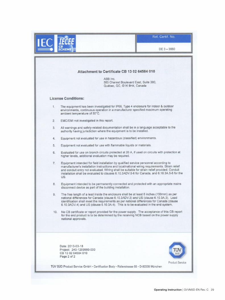
AppendixA:Certifications
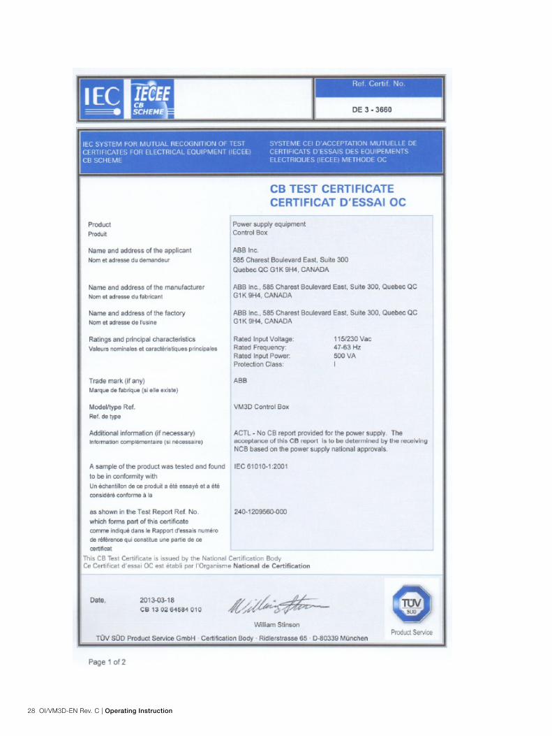
28 OI/VM3D-EN Rev. C | Operating Instruction
Operating Instruction | OI/VM3D-EN Rev. C 29

30 OI/VM3D-EN Rev. C | Operating Instruction

Operating Instruction | OI/VM3D-EN Rev. C 31

32 OI/VM3D-EN Rev. C | Operating Instruction

Operating Instruction | OI/VM3D-EN Rev. C 33

34 OI/VM3D-EN Rev. C | Operating Instruction

Operating Instruction | OI/VM3D-EN Rev. C 35
Notes

Contact us
ABB Analytical MeasurementsMeasurement & Analytics3400, Rue Pierre-ArdouinQuébec (Québec) G1P 0B2CanadaTel: 1 800 858 3847Tel: +1 418 877 8111Fax: +1 418 877 2834E-Mail: [email protected]
www.abb.com/level
NoteWe reserve the right to make technical changes or modify the contents of this document without prior notice. With regard to purchase orders, the agreed particulars shall prevail. ABB does not accept any responsibility whatsoever for potential errors or possible lack of information in this document.
We reserve all rights in this document and in the subject matter and illustrations contained therein. Any reproduction, disclosure to third parties or utilization of its contents - in whole or in parts – is forbidden without prior written consent of ABB.
Copyright© 2015 ABBAll rights reserved
3KXL323002R4201
Sales
Service
OI/
VM
3D-E
N R
ev C
9.
2015