operating instructions - chief · pdf fileoperating instructions multispot m80 resistance...
TRANSCRIPT
Operating instructions
MULTISPOT M80
Resistance Welder
Item no. 322921 Revision: 2.0 - Translation Version: 15th, December 2008
Be sure you have read and understood this operating manual before you carry out any works on and/or with this equipment.

Contents page 1.0 Warning notes – explanation of symbols 1 2.0 Description of equipment and overview 3 3.0 Start-up 5 3.1 Assembly of power supply unit and trolley 5 3.2 Compressed air connection 5 3.3 Mains power supply connection 6 3.4 Checking the mains voltage drop during welding 6 3.5 Malfunction indicator 7 4.0 Applications 8 5.0 Technical data 9 6.0 Working with spot-welding tongs 11 6.1 Preparation of welding area 11 6.2 Spot-welding with the tongs 13 6.3 Pulse welding 15 7.0 Operating the welding gun 17 7.1 Push spot welding 19 7.2 Pulling-out dents with washer 21 7.3 Pulling-out dents with high-speed planishing hammer “SAH" 23 7.4 Pushing-in dents 25 7.5 Shrinking sheet metal 25 7.6 Welding-on threaded studs 27 7.7 Welding-on T-pins 29 7.8 Positioning/fixing sheet metal (tacking) 31 8.0 Operating QUICKSPOT 31 9.0 Connection of AIRPULLER 32 10.0 Practical hints 32 11.0 Appendix/self-test and troubleshooting 33 11.1 Self-test 33 11.2 Checking LED displays and the solenoid valves 33 11.3 Mains-supply test and troubleshooting 33 11.4 Manual tool selection 35 11.5 Operating panel malfunction 35

- 1 -
1.0 Warning notes – explanation of symbols
Caution! Please note the following when using resistance welding units: The power supply unit and leads of the welding gun and the spot welding tongs generate a powerful electromagnetic field when in use. Electromagnetic fields can cause irritations of sense organs, nerve and muscle cells as well as malfunctions in physical aids (hearing aid, pacemaker etc.), electronic devices and data storage units. To prevent these effects, avoid a direct body contact with the welding cable. A safe distance of 15 cm between cable and body is recommended. Caution! Danger! Ignoring this warning may result in injury! Observe the notes! This is the only way to achieve satisfactory welding results. Work on the power supply unit may ONLY be performed by qualified electricians. Wear protective goggles and gloves!

- 2 -
AB Tool selecting keys (manual) see Appendix CD Gun functions selecting keys EF Sheet thickness selecting keys GH Fine adjustment keys time +/– Tools 1 Tongs, pulse welding 2 Tongs, spot welding 3 Gun 4 QUICKSPOT 5 AIRPULLER Working with gun 6 Push spot welding 7 Stud welding 8 Beat-out with washers, T-pins, riveting dies 9 High-speed planishing hammer 10 Anneal/shrink 11 Sheet thickness selector 12 Fine adjustment +/– 13 Mains plug symbos with LED “control mains voltage drop” (15, 16, 17) 14 LED malfunction

- 3 -
2.0 Description of equipment and overview
The MULTISPOT M80 resistance welding unit is designed for the special requirements of motor vehicle body repair. The power source is controlled by a micro-processor. After selecting the operating mode and the sheet steel thickness, the current and weld time will be assigned automatically and – where necessary and advisable – corrected accordingly. An audible alarm is performed, if the welding current is too low.
Further functions: – Automatic tool recognition – Integrated mains monitor recognises undervoltage – Automatic current rise, welding, current recognition and repressing – Easy and distinct operation by means of foil keyboard – Thermal probe controlled air-cooling for gun and tongs – Central connection for welding current, compressed air, cooling and control
wiring – Closed box for accessories in power supply unit – Sturdy trolley with basin for tools and accessories and electrode arms 60 Tongs holder * * in connection with spot 61 Cable holder welding tongs 62 Trolley frame **special accessories (item no. 63 Central connection socket pls. see from accessories list) 64 Balancer ** 65 Filter pressure reducer 66 Mains switch 67 Service box 68 Power supply unit 69 Screws 8 x 16 70 Screws 8 x 16 71 Trolley base 72 Roller 73 Guide wheel 74 Receptacle for pulling tool + SAH 75 Receptacle for electrode arms 76 Fastening screws 77 Electronics / operation panel

- 4 -
- 5 -
3.0 Start-up 3.1 Assembly of power supply unit and trolley
– Screw frame (62) to the trolley base with the screws provided (70) – Put power supply unit (68) on the trolley and fasten with screws provided (76). – Screw tongs holder* (60), cable holder (61), balancer** (64) to the frame. – (*= in connection with spot welding tongs **= special accessories) item number please see from accessories list).
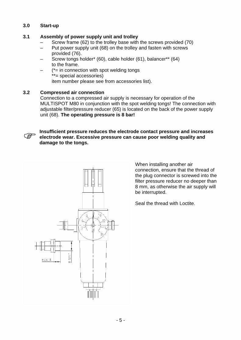
3.2 Compressed air connection
Connection to a compressed air supply is necessary for operation of the MULTISPOT M80 in conjunction with the spot welding tongs! The connection with adjustable filter/pressure reducer (65) is located on the back of the power supply unit (68). The operating pressure is 8 bar!
Insufficient pressure reduces the electrode contact pressure and increases electrode wear. Excessive pressure can cause poor welding quality and damage to the tongs.
When installing another air connection, ensure that the thread of the plug connector is screwed into the filter pressure reducer no deeper than 8 mm, as otherwise the air supply will be interrupted. Seal the thread with Loctite.

- 6 -
3.3 Mains power supply connection
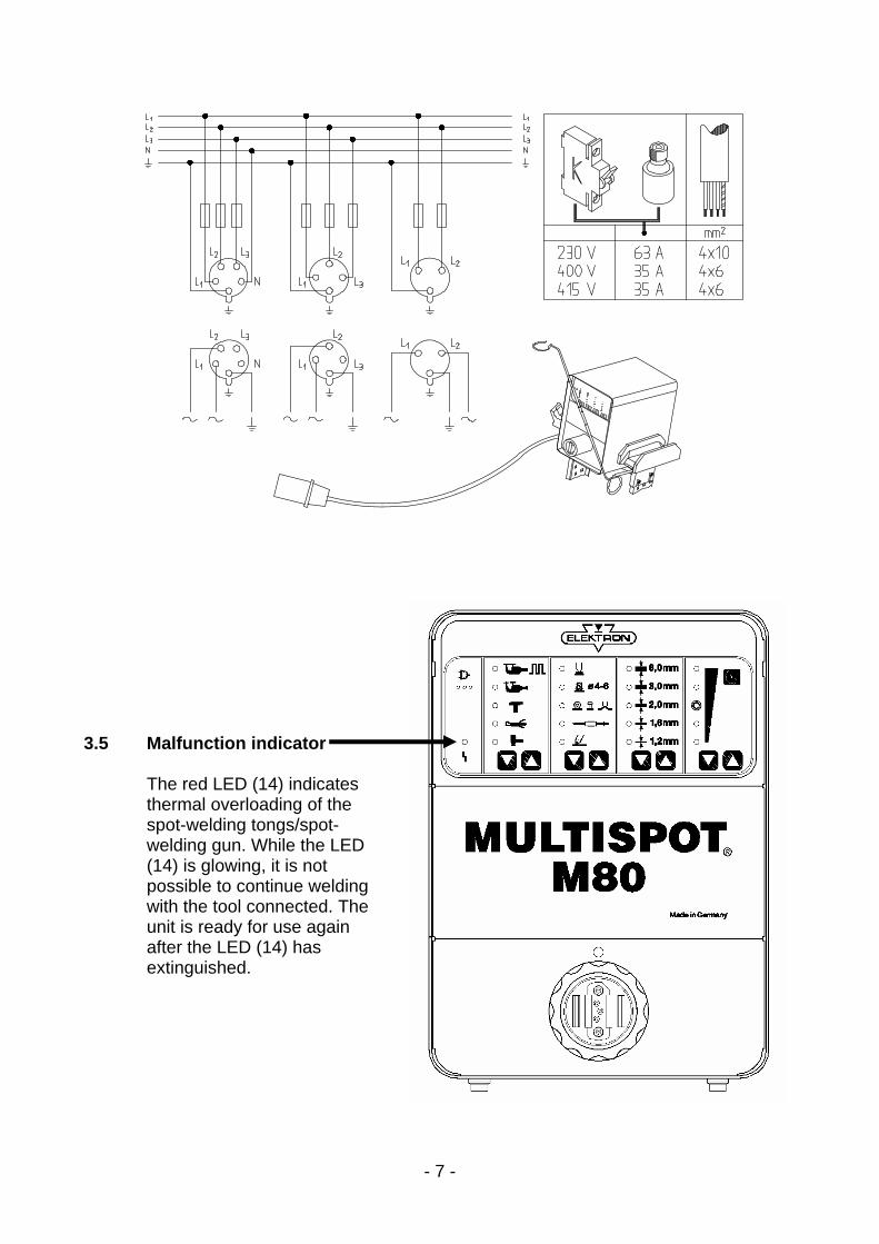
400 V 50/60 Hz (automatic switch-over) Connection to a 32 A Cekon socket Fuse: 32/35 A slow fuse or 32 A automatic circuit-breaker 230 V (190-240 V) 50/60 Hz (automatic switch-over) Connection to a 63 A Cekon socket Fuse: 63 A slow fuse or 63 A automatic circuit-breaker
3.4 Checking the mains voltage drop during welding
If the full performance of the MULTISPOT M80 is to be obtained, the mains voltage drop during welding must be kept as small as possible. The full test is described on Page 35, Chapter 11.3: Information about the mains drop during welding Display with 3 LEDs (15, 16, 17) under the mains plug symbol:
Green = mains OK Green/yellow = mains drop within tolerance range. Only yellow = considerable mains drop – welding performance impaired
If necessary, check mains cord, extension cables etc. or use thicker cables.
Red and = large mains drop with large drop in performance. warning tone: Welding is not possible. Welding current too low.
If necessary, check mains cord, extension cables etc. or use thicker cables. After 2 seconds, the display automatically reverts to green. After each welding operation, any mains voltage drop is displayed for 2 seconds.
- 7 -
3.5 Malfunction indicator
The red LED (14) indicates thermal overloading of the spot-welding tongs/spot-welding gun. While the LED (14) is glowing, it is not possible to continue welding with the tool connected. The unit is ready for use again after the LED (14) has extinguished.

- 8 -
4.0 Applications
Welding capacity:
Compressed-air pressure 8 bar
Electrode arm 120 mm
Programme switch Material Sheet thickness
Function in mm
Pulse welding with pneu-
matic spot welding tongs sheet steel 3.0 + 3.0
Spot welding with sheet steel 2.0 + 2.0
spot welding tongs pneumatic galvanized steel 1.5 + 1.5
Spot welding with
QUICKSPOT sheet steel 1.0 + 1.0
Push spot welding sheet steel 1.25 + 1.25
Setting for the following functions:
e. g. for sheet thickness 0.8 mm – choose range 1.6 mm
= 2 x 0.8 mm
Straightening out
with washer sheet steel 1.2
Airpuller sheet steel 1.0
Straightening out with
high-speed
planishing hammer sheet steel 0.8
Shrinking sheet steel 0.6 – 1.0
Stud welding Steel bolts Æ 4 – 6 mm
on sheet steel 2.0 mm

- 9 -
5.0 Technical data Power supply unit Supply voltage 400 V (380-415 V) 230V (190-240 V) Slow fuse 32/35 A* 63 A* Mains frequency 50/60 Hz 50/60 Hz Power supply cord 14.7 kVA 14.7 kVA Max. welding capacity 45 kVA 45 kVA Open-circuit voltage 12 V 12 V Welding current 6400A, 6400A, 3% duty cycle 3% duty cycle Welding time** 0.03 – 0.9 s 0.03 – 0.9 s automatic automatic adjustment adjustment Pulse welding time** 0.1 – 1.5 s 0.1 – 1.5 s automatic automatic adjustment adjustment Ambient temperature 40° C 40° C Type of protection IP21 IP21 Dimensions H/W/D mm 375/265/535 375/265/535 Weight power supply unit 54.5 kg 54.5 kg Dimensions of power supply unit in trolley H/W/D in mm 1020/517/600 1020/517/600 Total weight inc. accessories approx. 97.1 kg approx. 97.1 kg Spot welding tongs (pneumatic) Weight (without cable) 3.5 kg 3.5 kg Weight (with cable) 11.5 kg 11.5 kg Operating pressure 8 bar 8 bar Electrode arms 20 x 20 mm 20 x 20 mm Electrode contact pressure 1800 N 1800 N Welding cable Ø/length 120 mm²/2.5 m 120 mm²/2.5 m Electrodes Ø 12 mm Push spot welder Welding cable Ø /length 120 mm² / 2.2 m 120 mm² / 2.2 m Earth cable Ø /length 120 mm / 1.5 m 120 mm / 1.5 m Weight 6.15 kg 6.15 kg Electrodes Ø 10 mm 10 mm **Operation with a lower rating fuse at reduced power is possible. **+ automatic correction
- 10 -
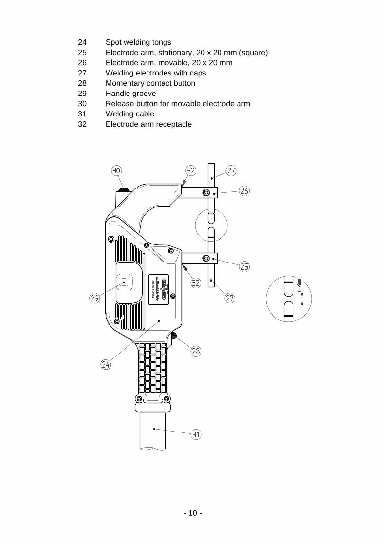
24 Spot welding tongs 25 Electrode arm, stationary, 20 x 20 mm (square) 26 Electrode arm, movable, 20 x 20 mm 27 Welding electrodes with caps 28 Momentary contact button 29 Handle groove 30 Release button for movable electrode arm 31 Welding cable 32 Electrode arm receptacle
- 11 -
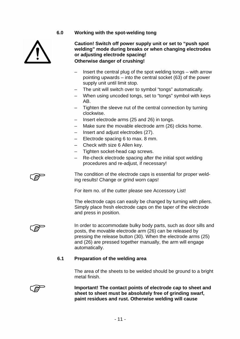
6.0 Working with the spot-welding tong
Caution! Switch off power supply unit or set to “push spot welding” mode during breaks or when changing electrodes or adjusting electrode spacing! Otherwise danger of crushing!
– Insert the central plug of the spot welding tongs – with arrow pointing upwards – into the central socket (63) of the power supply unit until limit stop.
– The unit will switch over to symbol “tongs” automatically. – When using uncoded tongs, set to “tongs” symbol with keys
AB. – Tighten the sleeve nut of the central connection by turning
clockwise. – Insert electrode arms (25 and 26) in tongs. – Make sure the movable electrode arm (26) clicks home. – Insert and adjust electrodes (27). – Electrode spacing 6 to max. 8 mm. – Check with size 6 Allen key. – Tighten socket-head cap screws. – Re-check electrode spacing after the initial spot welding
procedures and re-adjust, if necessary!
The condition of the electrode caps is essential for proper weld-ing results! Change or grind worn caps!
For item no. of the cutter please see Accessory List!
The electrode caps can easily be changed by turning with pliers. Simply place fresh electrode caps on the taper of the electrode and press in position. In order to accommodate bulky body parts, such as door sills and posts, the movable electrode arm (26) can be released by pressing the release button (30). When the electrode arms (25) and (26) are pressed together manually, the arm will engage automatically.
6.1 Preparation of the welding area
The area of the sheets to be welded should be ground to a bright metal finish.
Important! The contact points of electrode cap to sheet and sheet to sheet must be absolutely free of grinding swarf, paint residues and rust. Otherwise welding will cause

- 12 -
A B C D E F G H

- 13 -
6.2 Spot-welding with the tongs
Caution: Electromagnetic fields! Wear protective goggles and gloves! Electrodes heat up! Flying sparks!
– Switch on unit with mains switch (66). – Connect unit to the compressed air supply.
Ensure sufficient compressed air pressure, operating pressure is 8 bar! If necessary, adjust pressure with the filter pressure reducer (65). Insufficient compressed air will lead to excessive splatter and the weld spot may burn out. When the spot-welding tongs have been connected, the unit will switch automatically to the “tongs” symbol. In the case of uncoded tongs, select the “tong spot-welding” function with the program key AB, set sheet thickness with key EF; if necessary fine-adjust with key GH, e. g. galvanized sheets +, stainless steel sheets –. During welding procedures, keep hold of button of the tongs until welding process is automatically cut-off. Sequence of the welding program (see diagram on LHS): A – Pre-pressing 0.75 sec C – Welding with automatic timer-setting 0.03 to 0.45 sec E – Re-pressing 0.5 sec. Releasing key (28) prematurely will interrupt the functions “Pre-pressing” and “Welding”. Continued pressure on key (28) can extend the function “Re-press”.

- 14 -
A B C D E F G H

- 15 -
6.3 Pulse welding
Caution: Electromagnetic fields! Wear protective goggles and gloves! Electrodes heat up! Flying sparks!
This mode is used for spot-welding sheet metal of 2 x 1.5 mm or more, such as e.g. frame parts and gusset flanges. Preparations: – Ensure precise fitting of the sheets to be welded – no air
gap! – Clean sheets. – Electrode arms no longer than 250 mm. – Stable mains power supply. – Air pressure minimum 8 bar at filter pressure reducer. Welding: – Select mode “Tongs – pulse welding” with keys AB. – Select sheet thickness with keys EF. – Keep hold of key (28) of the tongs until welding process is
cut-off automatically. – Observe intervals of approx. 10 secs. Between spots to
prevent electrode caps from annealing. – The pulse welding option should only be used in the
exceptional cases mentioned above. – Overload: Continue welding once the red LED has
extinguished.

- 16 -
33 Welding gun 34 Button of welding gun 35 Grounding cable 36 Copper shoe 37 Lever clamp 38 Connection piece

- 17 -
7.0 Operating the welding gun
Preparation: – Insert the central plug of the welding gun (33) into the
central socket (63) until limit stop. Arrow on the plug pointing upwards.
– The unit will switch automatically to the “gun” symbol. – Select the “gun” tool with key AB (uncoded gun only). – Tighten the sleeve nut of the central connection by turning
clockwise. – Operating pressure at the filter pressure reducer min. 8 bar! – Connect the copper shoe (36) of the grounding cable (35) to
a bare point on the bodywork to be welded. Use lever clamp (37) provided or a mole wrench.
Before using the lever clamp (37), you have to weld on two 8 mm washers as close to the point of weld as possible, see section 7.2! In this case, press the copper shoe (36) of the grounding cable (35) firmly onto the metal sheet. This is the only way to obtain a good current transfer. Attention! The copper shoe (36) must always be connected to the metal sheet below the metal part of the body to be worked on. In any case avoid current transfer via hinges, door and bonnet locks, as these might otherwise be damaged!

- 18 -
A B C D E F G H

- 19 -
7.1 Push spot welding
Caution! Electromagnetic fields! Wear protective goggles and gloves! Electrodes heat up! Flying sparks! Only use the mode “push spot welding” is the area to be welded cannot be reached with the spot welding tongs! – Grind sheet surface and the area between the sheets until
completely bare. – In the welding area the sheets must have direct contact without
air gap. Otherwise welding is impossible. – Check the condition of welding electrodes and grind them, if
necessary. – Ensure perfect earthing to bottom sheet as close to the welding
spot as possible. – Select mode “push spot welding” with keys CD. – Select sheet thickness with keys EF (thicknesses of more than
2 x 1.5 = 3 mm cannot be selected!). – Press the welding gun to the welding point with a pressure of
approx. 8 – 12 kgs. Excessive contact pressure will lead to poor welding results! – Keep hold of button (34) of the gun until welding process has
ended (if necessary fine-adjust with keys GH). – Always spot-weld thinner sheets to thicker ones! – Proceed with welding towards the grounding point. Spacing between the welding spots approx. 20 mm.
- 20 -
A B C D E F G H
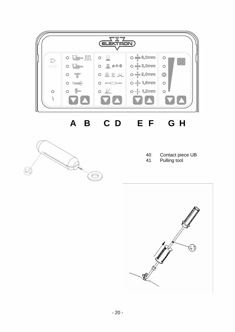
40 Contact piece UB 41 Pulling tool

- 21 -
7.2 Pulling-out dents with washer
– Grind the damaged area to a bright metal finish. – Insert contact piece (40) into welding gun. – Select “washer” mode with keys CD. – Select sheet thickness with keys EF (Sheet steel thickness
more than 2 x 1.5 = 3 mm cannot be selected). – Fine-adjust +/– with keys GH, if necessary. – Position welding gun (33) with washer in the area of the dent. – Press button (34) of the gun, welding time is controlled
automatically. – Hook pulling tool into the washer (41) and carefully beat out the
dent. – Remove washer by twisting. – Only twist the washer off, otherwise holes in the sheet steel
could result. 8 mm Washer Always beat out major dents from the outside, working inwards. Use bright washers instead of galvanized. Adjust setting with keys GH according to size and type of the dent, if necessary.

- 22 -
A B C D E F G H
42 High-speed planishing hammer “SAH”, special accessory!

- 23 -
7.3 High-speed planishing hammer “SAH” (special accessory)
Small dents, scratches or hail pitting can easily be removed with the high-speed planishing hammer (42). – Grind damaged area to a bright metal finish. – Insert high-speed planishing hammer (42) (with weld on tip) into the
gun. – Properly tighten union nut. – Select “SAH” mode with keys CD. – Select sheet thickness with keys EF (Sheet steel thickness above
2 x 0.8 = 1.6 mm cannot be selected). – Fine-adjust +/– with keys GH, if necessary. – Position weld-on tip of the hammer (42) in the damaged area. – Press button (34) of the gun and weld-on welding tip. – Beat out the dent. – Twist the high-speed planishing hammer (SAH) off the sheet steel.
Select the weld time as short as possible. – From time to time, dress the weld-on tip with a file. Repeat the procedure until the damaged area is entirely repaired. Heavy dents only remove with extractor tool and 8mm washer, as otherwise the welding gun might be damaged! If the weld-on tip is worn out, it should be replaced. For replacement unscrew the socket-head cap screw at the top of the hammer (SAH) and remove the worn out weld-on tip. Position new weld-on tip and properly tighten socket-head capscrew! For item number please see spare parts list.

- 24 -
A B C D E F G H
39 Carbon electrode 40 Contact piece U-B

- 25 -
7.3 Pushing-in dents
Small high spots dents caused by overlapping load in the boot or by beating out with pulling tool can easily be flattened with contact piece (40) (only for sheets up to 1 mm thickness). – Insert contact piece (40) into the gun (33). – Thoroughly tighten union nut. – Select “pushing in dent” mode with keys CD. – Select sheet thickness (» projection) with keys EF. – Fine-adjust with keys GH, if necessary. – Position welding gun (33) with contact piece (40) on the dent
and press firmly. – Press button (34) of the gun. – The welding program performs automatically. Do not lift off welding gun until the welding time has expired!
7.5 Shrinking sheet metal
– Grind damaged area to a bright metal finish. – Insert carbon electrode (39) into contact piece of the welding
gun (33). – Select “anneal/shrink” with keys CD (time controller is now
inoperative). – Locate the damaged area by finger pressure. – Position carbon electrode (39) in the centre of the damaged
area. – Press and keep hold of button (34) of the gun and heat the
metal sheet with spiral motions from the centre outwards. – Immediately quench the sheet with a wet cloth or compressed
air. Repeat if necessary. If necessary, the degree of annealing can be increased or decreased by one increment with the keys EF. Danger! The carbon electrode becomes red-hot! Danger of injury and fire! Wear protective gloves!
- 26 -
A B C D E F G H
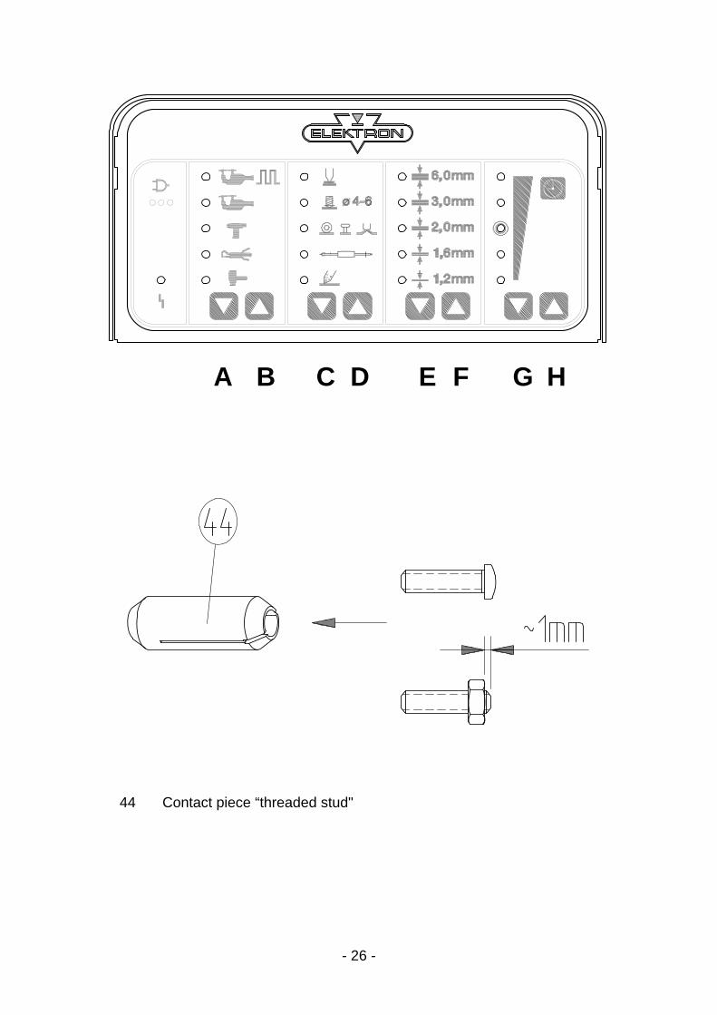
44 Contact piece “threaded stud"

- 27 -
7.6 Welding-on threaded studs
With the MULTISPOT M80 it is possible to weld on threaded studs of 4, 5, 6 mm diameter. Please use the appropriate contact pieces! SB 4 for Ø 4 mm SB 5 for Ø 5 mm SB 6 for Ø 6 mm – Insert appropriate contact piece (44) into welding gun (33). – Properly tighten union nut. – Insert threaded stud into contact piece (44) until limit stop. – Select “weld on studs” mode with keys CD. – Select sheet thickness with keys EF. – Press key G once for studs of 4 mm Ø. – Press key H once for studs of 6 mm Ø. – Position welding gun (33) with the stud at the welding point and
press slightly. – Press and keep hold of button (34) of the gun until welding program
has ended. Threaded studs without collar can also be welded on. Use a nut in place of a collar. The part to be welded should project from the nut about 1 to 2 mm. Welding procedure as described above.

- 28 -
A B C D E F G H
45 Contact piece TST 3 Item no. 407 227 46 T-pin 3 x 3.2 Item no. 408 596 47 T-pin 3 x 4.5 Item no. 408 597 48 Fitting piece Golf 2 Item no. 313 451 special accessory 49 Fitting piece Passat B 3 Item no. 315 671 special accessory 50 Fitting piece Porsche Item no. 314 465 special accessory 51 Fitting piece Golf 3/Vento Item no. 317 962 special accessory 52 Contact piece TST 5 Item no. 408 540 special accessory 53 T-pin 5 x 10 Item no. 408 571 special accessory
- 29 -
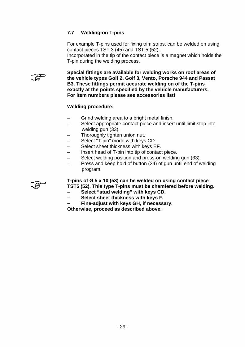
7.7 Welding-on T-pins For example T-pins used for fixing trim strips, can be welded on using contact pieces TST 3 (45) and TST 5 (52). Incorporated in the tip of the contact piece is a magnet which holds the T-pin during the welding process. Special fittings are available for welding works on roof areas of the vehicle types Golf 2, Golf 3, Vento, Porsche 944 and Passat B3. These fittings permit accurate welding on of the T-pins exactly at the points specified by the vehicle manufacturers. For item numbers please see accessories list! Welding procedure: – Grind welding area to a bright metal finish. – Select appropriate contact piece and insert until limit stop into
welding gun (33). – Thoroughly tighten union nut. – Select “T-pin” mode with keys CD. – Select sheet thickness with keys EF. – Insert head of T-pin into tip of contact piece. – Select welding position and press-on welding gun (33). – Press and keep hold of button (34) of gun until end of welding
program. T-pins of Ø 5 x 10 (53) can be welded on using contact piece TST5 (52). This type T-pins must be chamfered before welding. – Select “stud welding” with keys CD. – Select sheet thickness with keys F. – Fine-adjust with keys GH, if necessary. Otherwise, proceed as described above.

- 30 -
A B C D E F G H

- 31 -
7.8 Fixing sheet metal parts (tacking) Body sections frequently have to be fixed temporarily for the purpose of alignment. In some areas, clamps cannot be used. In such cases, the sections can be fixed by tack welding with the MULTISPOT M80. Washers from which ¼ has been cut out can be used as fixing aid. – Insert contact piece (40) for washers into welding gun (33) to limit
stop. – Properly tighten union nut. – Cut off approx. ¼ of a washer of 8 mm Ø with a side cutter. – Insert prepared washer into contact piece (40). – Select “washer weld” with keys CD. – Select sheet thickness with keys EF. – Position the washer and press-on. Press and keep hold of button (34) of the gun until end of automatic welding program.
8.0 QUICKSPOT (special accessory) – Connect QUICKSPOT to the central socket (63). – The unit will switch automatically to the QUICKSPOT symbol. – Select “tool QUICKSPOT” with buttons AB (uncoded QUICKSPOT only). – Select sheet thickness with keys EF. Sheet thicknesses above 2 x 1 mm cannot be selected; for such cases please use the pneumatic spot welding tongs. – Fine-adjust with keys GH, if necessary. – Mit Tasten GH ggf. Feineinstellung vornehmen. – Cooling air is constantly flowing, switch off with mains switch (66), see also operating instructions for QUICKSPOT.

- 32 -
9.0 Connection of AIRPULLER
– Connect AIRPULLER to central socket (63). – The unit will switch automatically to the AIRPULLER symbol. – Select “tool AIRPULLER” with keys AB (uncoded AIRPULLER
only). – In “planishing” mode select sheet thickness (up to a max. of
2 x 1 mm) with keys EF. – In “annealing” mode select “anneal” symbol with keys CD. – Fine-adjust with keys GH, if necessary. Operating the AIRPULLER please see operating instructions AIRPULLER.
10.0 Practical hints
When push spot welding pull metal sheet
When push spot welding properly press on copper shoe of grounding cable from below.
When push spot welding firmly press on metal sheet with screw driver

- 33 -
11.0 Appendix/self-test and troubleshooting 11.1 Self-test
The MULTISPOT M80 is provided with a self-test program to check and evaluate the functions of the unit.The results are shown via LED.
11.2 Checking the LED displays and the solenoid valves – Detach the tongs or gun from the power supply unit. – Connect the unit to the power supply. – Connect 8 bar compressed air supply. – Switch the unit OFF. – Depress key “A”, switch the unit ON, release the key “A”. All the LEDs on the operating panel will be switched on in sequence. At the end of the LED test, the cooling and the pneumatic solenoid valve will each be opened for 1 sec. The test ends after 5 cycles or when any key is pressed.
11.3 Mains-supply test and troubleshooting – Connect spot-welding tongs – Clean electrode caps/ separation 6mm. – Set to an overall plate thickness of 3mm/ 8 bar air pressure – Perform short-circuit weld (i.e. no plate) = maximum mains load. If spot-weld tongs are not available, perform the test in the following way: – Connect gun and select the “Push spot weld” mode: C D keys. – Set plate thickness to 2mm: E F keys. Time to max: G H keys – Insert spot electrode in the gun. – Press the spot electrode firmly onto the earth shoe (36), press the the gun
trigger and perform the short-circuit weld. Evaluating the test LEDs under the mains plug symbol: Green No mains drop, full welding performance available Green+yellow Insignificant mains drop, good welding performance Yellow Larger mains drop, no longer possible to weld plates thicker than 0.8 mm Yellow+red Critical mains drop, max. welding thickness <= 0.8 mm. Red Mains drop too great, spot welding is not possible.
- 34 -
Causes of power drop under load: – Extension cables too long. – Mains power cord from power point (fuse box) to plug is too long or cable
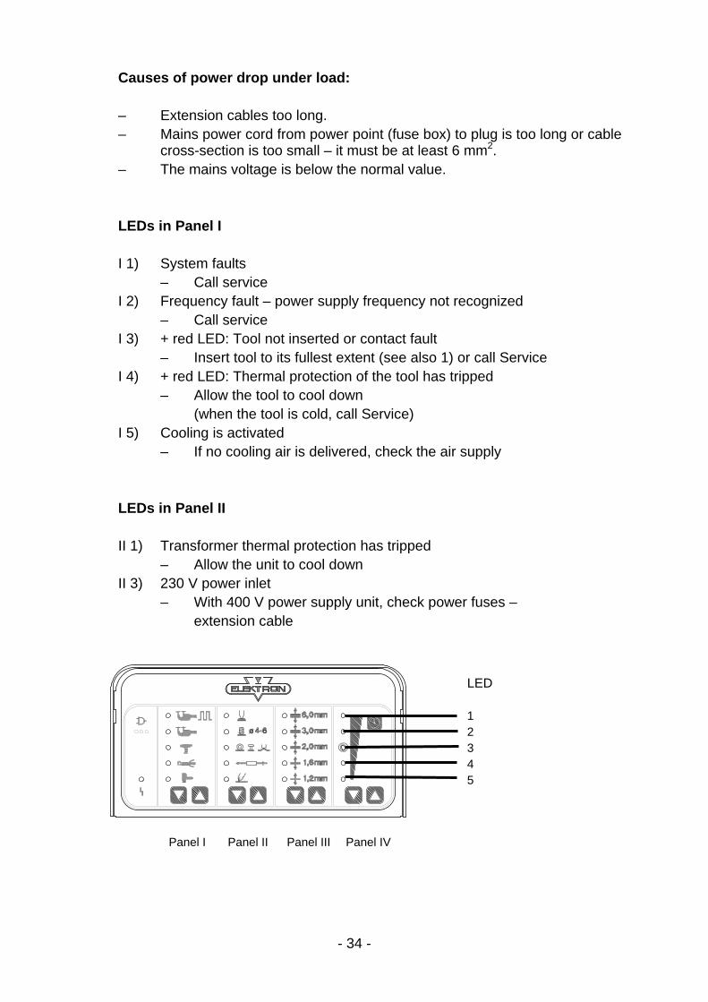
cross-section is too small – it must be at least 6 mm2. – The mains voltage is below the normal value. LEDs in Panel I I 1) System faults – Call service I 2) Frequency fault – power supply frequency not recognized – Call service I 3) + red LED: Tool not inserted or contact fault – Insert tool to its fullest extent (see also 1) or call Service I 4) + red LED: Thermal protection of the tool has tripped – Allow the tool to cool down (when the tool is cold, call Service) I 5) Cooling is activated – If no cooling air is delivered, check the air supply LEDs in Panel II II 1) Transformer thermal protection has tripped – Allow the unit to cool down II 3) 230 V power inlet – With 400 V power supply unit, check power fuses – extension cable
Panel I Panel II Panel III Panel IV
LED 1 2 3 4 5

- 35 -
II 4) 400 V power inlet – With 230 V power supply unit:
CAUTION switch the unit OFF immediately! Supply voltage is too high.
LEDs in Panel III III 1) Display of supply frequency 50 Hz III 2) Display of supply frequency 60 Hz III 4) Display: Weld current measurement has been carried out. Display of weld current in Panel IV. LEDs in Panel IV Display of weld current for tongs, push spot welding, stud welding, QUICKSPOT = 1 LED per 1000 A Minimum displayable current: 3000 A = IV 5 Maximum displayable current > 7000 A = IV 1 Display of weld current for Airpuller, washer welding, high-speed planishing hammer, annealing = 1 LED per 500 A Minimum displayable current: 500 A = IV 5 Maximum displayable current: 2500 A = IV 1 11.4 Manual tool selection
In an emergency or for service examination, it is possible to bypass automatic tool recognition. – Switch the unit OFF. – Connect the tool to the unit. – Switch the unit ON, depressing the tool key. – Select the tool required with the keys AB. – Reset on tool change or switch the unit off.
11.5 Operation panel malfunction
In the case of a malfunction in the operating panel, that is to say there is no reaction when a button is pressed, if LED displays illuminate incorrectly, etc., switch the unit OFF and switch ON again after approx. 2 sec. This will clear the malfunction
Subject to technical alterations without notice. ELEKTRON-BREMEN Elektrotechnik GmbH · Am Hohentorshafen 17-19 · 28197 Bremen
Tel + 49 421 54906-906 · Fax +49 421 54906-19 · [email protected] · www.elektron-bremen.de